syncro cs 9361-8i and syncro cs 9380-8e solution user guide
TRANSCRIPT
Syncro® CS 9361-8i and Syncro CS 9380-8e Solution User Guide
Version 2.0 October 2014
55411-00, Rev. B

For a comprehensive list of changes to this document, see the Revision History.
Avago Technologies, the A logo, LSI, and Storage by LSI, Syncro, MegaRAID, MegaRaid Storage Manager, CacheCade, and CacheVault are trademarks of Avago Technologies in the United States and other countries. All other brand and product names may be trademarks of their respective companies.
Data subject to change. Copyright © 2014 Avago Technologies. All Rights Reserved.
Corporate Headquarters Email Website
San Jose, CA [email protected] www.lsi.com
800-372-2447
Syncro CS 9361-8i and Syncro CS 9380-8e Solution User GuideOctober 2014

Syncro CS 9361-8i and Syncro CS 9380-8e Solution User GuideOctober 2014
Table of Contents
Avago Technologies- 3 -
Table of Contents
Chapter 1: Introduction . . . . . . . . . . . . . . . . . . . . . . . . . . . . . . . . . . . . . . . . . . . . . . . . . . . . . . . . . . . . . . . . . . . . . . . . . . . . . . . . . . . . . . . . . . . . . . . . . . . . . . . . . 5
1.1 Concepts of High-Availability DAS . . . . . . . . . . . . . . . . . . . . . . . . . . . . . . . . . . . . . . . . . . . . . . . . . . . . . . . . . . . . . . . . . . . . . . . . . . . . . . . . . . . . . . . . . . . . . . . . . . . 51.2 HA-DAS Terminology . . . . . . . . . . . . . . . . . . . . . . . . . . . . . . . . . . . . . . . . . . . . . . . . . . . . . . . . . . . . . . . . . . . . . . . . . . . . . . . . . . . . . . . . . . . . . . . . . . . . . . . . . . . . . . . 61.3 Syncro CS 9361-8i and Syncro CS 9380-8e Solution Features . . . . . . . . . . . . . . . . . . . . . . . . . . . . . . . . . . . . . . . . . . . . . . . . . . . . . . . . . . . . . . . . . . . . . . . . . 61.4 Hardware Compatibility . . . . . . . . . . . . . . . . . . . . . . . . . . . . . . . . . . . . . . . . . . . . . . . . . . . . . . . . . . . . . . . . . . . . . . . . . . . . . . . . . . . . . . . . . . . . . . . . . . . . . . . . . . . . 71.5 Overview of Cluster Setup, Planned Failovers, and Firmware Updates . . . . . . . . . . . . . . . . . . . . . . . . . . . . . . . . . . . . . . . . . . . . . . . . . . . . . . . . . . . . . . . . 81.6 Performance Considerations . . . . . . . . . . . . . . . . . . . . . . . . . . . . . . . . . . . . . . . . . . . . . . . . . . . . . . . . . . . . . . . . . . . . . . . . . . . . . . . . . . . . . . . . . . . . . . . . . . . . . . . . 81.7 Known Third-Party Issues . . . . . . . . . . . . . . . . . . . . . . . . . . . . . . . . . . . . . . . . . . . . . . . . . . . . . . . . . . . . . . . . . . . . . . . . . . . . . . . . . . . . . . . . . . . . . . . . . . . . . . . . . . . 9
1.7.1 Non-shared VD is Pulled into Windows Operating System Cluster During Cluster Creation . . . . . . . . . . . . . . . . . . . . . . . . . . . . . . . . . . . . . . 91.7.2 Delayed Write Failed Error During IO Stress Test . . . . . . . . . . . . . . . . . . . . . . . . . . . . . . . . . . . . . . . . . . . . . . . . . . . . . . . . . . . . . . . . . . . . . . . . . . . . . . . 91.7.3 Remote IO Failure Observed in SLES11 SP2 While Removing the SAS Cables of the Owner Node . . . . . . . . . . . . . . . . . . . . . . . . . . . . . . . . 9
Chapter 2: Creating the Cluster . . . . . . . . . . . . . . . . . . . . . . . . . . . . . . . . . . . . . . . . . . . . . . . . . . . . . . . . . . . . . . . . . . . . . . . . . . . . . . . . . . . . . . . . . . . . . . . . . 10
2.1 Creating Virtual Drives on the Controller Nodes . . . . . . . . . . . . . . . . . . . . . . . . . . . . . . . . . . . . . . . . . . . . . . . . . . . . . . . . . . . . . . . . . . . . . . . . . . . . . . . . . . . . . 102.1.1 Creating Shared or Exclusive VDs with the CTRL-R Utility . . . . . . . . . . . . . . . . . . . . . . . . . . . . . . . . . . . . . . . . . . . . . . . . . . . . . . . . . . . . . . . . . . . . . 102.1.2 Selecting Additional Virtual Drive Properties . . . . . . . . . . . . . . . . . . . . . . . . . . . . . . . . . . . . . . . . . . . . . . . . . . . . . . . . . . . . . . . . . . . . . . . . . . . . . . . . . 142.1.3 Creating Shared or Exclusive VDs with StorCLI . . . . . . . . . . . . . . . . . . . . . . . . . . . . . . . . . . . . . . . . . . . . . . . . . . . . . . . . . . . . . . . . . . . . . . . . . . . . . . . . 152.1.4 Creating Shared or Exclusive VDs with MSM . . . . . . . . . . . . . . . . . . . . . . . . . . . . . . . . . . . . . . . . . . . . . . . . . . . . . . . . . . . . . . . . . . . . . . . . . . . . . . . . . . 16
2.2 Creating the Cluster in Windows . . . . . . . . . . . . . . . . . . . . . . . . . . . . . . . . . . . . . . . . . . . . . . . . . . . . . . . . . . . . . . . . . . . . . . . . . . . . . . . . . . . . . . . . . . . . . . . . . . . 202.2.1 Prerequisites for Cluster Setup . . . . . . . . . . . . . . . . . . . . . . . . . . . . . . . . . . . . . . . . . . . . . . . . . . . . . . . . . . . . . . . . . . . . . . . . . . . . . . . . . . . . . . . . . . . . . . . 202.2.2 Creating the Failover Cluster . . . . . . . . . . . . . . . . . . . . . . . . . . . . . . . . . . . . . . . . . . . . . . . . . . . . . . . . . . . . . . . . . . . . . . . . . . . . . . . . . . . . . . . . . . . . . . . . . 212.2.3 Validating the Failover Cluster Configuration . . . . . . . . . . . . . . . . . . . . . . . . . . . . . . . . . . . . . . . . . . . . . . . . . . . . . . . . . . . . . . . . . . . . . . . . . . . . . . . . . 22
2.3 Creating the Cluster in Red Hat Enterprise Linux (RHEL) and CentOS . . . . . . . . . . . . . . . . . . . . . . . . . . . . . . . . . . . . . . . . . . . . . . . . . . . . . . . . . . . . . . . . . 232.3.1 Prerequisites for Cluster Setup . . . . . . . . . . . . . . . . . . . . . . . . . . . . . . . . . . . . . . . . . . . . . . . . . . . . . . . . . . . . . . . . . . . . . . . . . . . . . . . . . . . . . . . . . . . . . . . 232.3.2 Creating the Cluster . . . . . . . . . . . . . . . . . . . . . . . . . . . . . . . . . . . . . . . . . . . . . . . . . . . . . . . . . . . . . . . . . . . . . . . . . . . . . . . . . . . . . . . . . . . . . . . . . . . . . . . . . 252.3.3 Configure the Logical Volumes and Apply GFS2 File System . . . . . . . . . . . . . . . . . . . . . . . . . . . . . . . . . . . . . . . . . . . . . . . . . . . . . . . . . . . . . . . . . . 272.3.4 Add a Fence Device . . . . . . . . . . . . . . . . . . . . . . . . . . . . . . . . . . . . . . . . . . . . . . . . . . . . . . . . . . . . . . . . . . . . . . . . . . . . . . . . . . . . . . . . . . . . . . . . . . . . . . . . . 282.3.5 Create a Failover Domain . . . . . . . . . . . . . . . . . . . . . . . . . . . . . . . . . . . . . . . . . . . . . . . . . . . . . . . . . . . . . . . . . . . . . . . . . . . . . . . . . . . . . . . . . . . . . . . . . . . . 292.3.6 Add Resources to the Cluster . . . . . . . . . . . . . . . . . . . . . . . . . . . . . . . . . . . . . . . . . . . . . . . . . . . . . . . . . . . . . . . . . . . . . . . . . . . . . . . . . . . . . . . . . . . . . . . . 302.3.7 Create a Quorum Disk . . . . . . . . . . . . . . . . . . . . . . . . . . . . . . . . . . . . . . . . . . . . . . . . . . . . . . . . . . . . . . . . . . . . . . . . . . . . . . . . . . . . . . . . . . . . . . . . . . . . . . . 332.3.8 Create Service Groups . . . . . . . . . . . . . . . . . . . . . . . . . . . . . . . . . . . . . . . . . . . . . . . . . . . . . . . . . . . . . . . . . . . . . . . . . . . . . . . . . . . . . . . . . . . . . . . . . . . . . . . 372.3.9 Mount the NFS Resource from the Remote Client . . . . . . . . . . . . . . . . . . . . . . . . . . . . . . . . . . . . . . . . . . . . . . . . . . . . . . . . . . . . . . . . . . . . . . . . . . . . . 39
2.4 Creating the Cluster in SuSE Linux Enterprise Server (SLES) . . . . . . . . . . . . . . . . . . . . . . . . . . . . . . . . . . . . . . . . . . . . . . . . . . . . . . . . . . . . . . . . . . . . . . . . . . 392.4.1 Prerequisites for Cluster Setup . . . . . . . . . . . . . . . . . . . . . . . . . . . . . . . . . . . . . . . . . . . . . . . . . . . . . . . . . . . . . . . . . . . . . . . . . . . . . . . . . . . . . . . . . . . . . . . 402.4.2 Creating the Cluster . . . . . . . . . . . . . . . . . . . . . . . . . . . . . . . . . . . . . . . . . . . . . . . . . . . . . . . . . . . . . . . . . . . . . . . . . . . . . . . . . . . . . . . . . . . . . . . . . . . . . . . . . 432.4.3 Bringing the Cluster Online . . . . . . . . . . . . . . . . . . . . . . . . . . . . . . . . . . . . . . . . . . . . . . . . . . . . . . . . . . . . . . . . . . . . . . . . . . . . . . . . . . . . . . . . . . . . . . . . . . 492.4.4 Configuring the NFS Resource with STONITH SBD Fencing . . . . . . . . . . . . . . . . . . . . . . . . . . . . . . . . . . . . . . . . . . . . . . . . . . . . . . . . . . . . . . . . . . . . 492.4.5 Adding NFS Cluster Resources . . . . . . . . . . . . . . . . . . . . . . . . . . . . . . . . . . . . . . . . . . . . . . . . . . . . . . . . . . . . . . . . . . . . . . . . . . . . . . . . . . . . . . . . . . . . . . . 522.4.6 Mounting NFS in the Remote Client . . . . . . . . . . . . . . . . . . . . . . . . . . . . . . . . . . . . . . . . . . . . . . . . . . . . . . . . . . . . . . . . . . . . . . . . . . . . . . . . . . . . . . . . . . 55
Chapter 3: System Administration . . . . . . . . . . . . . . . . . . . . . . . . . . . . . . . . . . . . . . . . . . . . . . . . . . . . . . . . . . . . . . . . . . . . . . . . . . . . . . . . . . . . . . . . . . . . . . 56
3.1 High Availability Properties . . . . . . . . . . . . . . . . . . . . . . . . . . . . . . . . . . . . . . . . . . . . . . . . . . . . . . . . . . . . . . . . . . . . . . . . . . . . . . . . . . . . . . . . . . . . . . . . . . . . . . . . 563.2 Understanding Failover Operations . . . . . . . . . . . . . . . . . . . . . . . . . . . . . . . . . . . . . . . . . . . . . . . . . . . . . . . . . . . . . . . . . . . . . . . . . . . . . . . . . . . . . . . . . . . . . . . . 57
3.2.1 Understanding and Using Planned Failover . . . . . . . . . . . . . . . . . . . . . . . . . . . . . . . . . . . . . . . . . . . . . . . . . . . . . . . . . . . . . . . . . . . . . . . . . . . . . . . . . . 583.2.2 Understanding Unplanned Failover . . . . . . . . . . . . . . . . . . . . . . . . . . . . . . . . . . . . . . . . . . . . . . . . . . . . . . . . . . . . . . . . . . . . . . . . . . . . . . . . . . . . . . . . . . 63
3.3 Updating the Syncro CS Controller Firmware . . . . . . . . . . . . . . . . . . . . . . . . . . . . . . . . . . . . . . . . . . . . . . . . . . . . . . . . . . . . . . . . . . . . . . . . . . . . . . . . . . . . . . . 643.4 Updating the MegaRAID Driver . . . . . . . . . . . . . . . . . . . . . . . . . . . . . . . . . . . . . . . . . . . . . . . . . . . . . . . . . . . . . . . . . . . . . . . . . . . . . . . . . . . . . . . . . . . . . . . . . . . . 65
3.4.1 Updating the MegaRAID Driver in Windows Server 2008 R2 . . . . . . . . . . . . . . . . . . . . . . . . . . . . . . . . . . . . . . . . . . . . . . . . . . . . . . . . . . . . . . . . . . . 653.4.2 Updating the MegaRAID Driver in Windows Server 2012 . . . . . . . . . . . . . . . . . . . . . . . . . . . . . . . . . . . . . . . . . . . . . . . . . . . . . . . . . . . . . . . . . . . . . . 673.4.3 Updating the Red Hat Linux System Driver . . . . . . . . . . . . . . . . . . . . . . . . . . . . . . . . . . . . . . . . . . . . . . . . . . . . . . . . . . . . . . . . . . . . . . . . . . . . . . . . . . . 683.4.4 Updating the SuSE Linux Enterprise Server 11 Driver . . . . . . . . . . . . . . . . . . . . . . . . . . . . . . . . . . . . . . . . . . . . . . . . . . . . . . . . . . . . . . . . . . . . . . . . . 68
3.5 Performing Preventive Measures on Disk Drives and VDs . . . . . . . . . . . . . . . . . . . . . . . . . . . . . . . . . . . . . . . . . . . . . . . . . . . . . . . . . . . . . . . . . . . . . . . . . . . . 69

Syncro CS 9361-8i and Syncro CS 9380-8e Solution User GuideOctober 2014
Table of Contents
Avago Technologies- 4 -
Chapter 4: Troubleshooting . . . . . . . . . . . . . . . . . . . . . . . . . . . . . . . . . . . . . . . . . . . . . . . . . . . . . . . . . . . . . . . . . . . . . . . . . . . . . . . . . . . . . . . . . . . . . . . . . . . . 70
4.1 Verifying HA-DAS Support in Tools and the OS Driver . . . . . . . . . . . . . . . . . . . . . . . . . . . . . . . . . . . . . . . . . . . . . . . . . . . . . . . . . . . . . . . . . . . . . . . . . . . . . . . 704.2 Confirming SAS Connections . . . . . . . . . . . . . . . . . . . . . . . . . . . . . . . . . . . . . . . . . . . . . . . . . . . . . . . . . . . . . . . . . . . . . . . . . . . . . . . . . . . . . . . . . . . . . . . . . . . . . . . 71
4.2.1 Using Crtl-R to View Connections for Controllers, Expanders, and Drives . . . . . . . . . . . . . . . . . . . . . . . . . . . . . . . . . . . . . . . . . . . . . . . . . . . . . . 714.2.2 Using StorCLI to Verify Dual-Ported SAS Addresses to Disk Drives . . . . . . . . . . . . . . . . . . . . . . . . . . . . . . . . . . . . . . . . . . . . . . . . . . . . . . . . . . . . . 724.2.3 Using MSM to Verify Dual-Ported SAS Addresses to Disk Drives . . . . . . . . . . . . . . . . . . . . . . . . . . . . . . . . . . . . . . . . . . . . . . . . . . . . . . . . . . . . . . . 73
4.3 Handling Pinned Cache on Both Nodes . . . . . . . . . . . . . . . . . . . . . . . . . . . . . . . . . . . . . . . . . . . . . . . . . . . . . . . . . . . . . . . . . . . . . . . . . . . . . . . . . . . . . . . . . . . . . 744.4 Error Situations and Solutions . . . . . . . . . . . . . . . . . . . . . . . . . . . . . . . . . . . . . . . . . . . . . . . . . . . . . . . . . . . . . . . . . . . . . . . . . . . . . . . . . . . . . . . . . . . . . . . . . . . . . . 754.5 Event Messages and Error Messages . . . . . . . . . . . . . . . . . . . . . . . . . . . . . . . . . . . . . . . . . . . . . . . . . . . . . . . . . . . . . . . . . . . . . . . . . . . . . . . . . . . . . . . . . . . . . . . . 76

Avago Technologies- 5 -
Syncro CS 9361-8i and Syncro CS 9380-8e Solution User GuideOctober 2014
Chapter 1: Introduction Concepts of High-Availability DAS
Chapter 1: Introduction
This document explains how to set up high-availability direct-attached storage (HA-DAS) clustering on a Syncro CS 9361-8i and Syncro CS 9380-8e configuration after you configure the hardware and install the operating system.
The Syncro CS solution provides fault tolerance capabilities as a key part of a high-availability data storage system. The Syncro CS solution combines redundant servers, Avago HA-DAS RAID controllers, computer nodes, cable connections, common SAS JBOD enclosures, and dual-ported SAS storage devices.
The redundant components and software technologies provide a high-availability system with ongoing service that is not interrupted by the following events:
The failure of a single internal node does not interrupt service because the solution has multiple nodes with cluster failover.
An expander failure does not interrupt service because the dual expanders in every enclosure provide redundant data paths.
A drive failure does not interrupt service because RAID fault tolerance is part of the configuration. A system storage expansion or maintenance activity can be completed without requiring an interruption of
service because of redundant components, management software, and maintenance procedures.
1.1 Concepts of High-Availability DAS
In terms of data storage and processing, High Availability (HA) means a computer system design that ensures a high level of operational continuity and data access reliability over a long period of time. High-availability systems are critical to the success and business needs of small and medium-sized business (SMB) customers, such as retail outlets and health care offices, who cannot afford to have their computer systems go down. An HA-DAS solution enables customers to maintain continuous access to and use of their computer system. Shared direct-attached drives are accessible to multiple servers, thereby maintaining ease of use and reducing storage costs.
A cluster is a group of computers working together to run a common set of applications and to present a single logical system to the client and application. Failover clustering provides redundancy to the cluster group to maximize up-time by utilizing fault-tolerant components. In the example of two servers with shared storage that comprise a failover cluster, when a server fails, the failover cluster automatically moves control of the shared resources to the surviving server with no interruption of processing. This configuration allows seamless failover capabilities in the event of planned failover (maintenance mode) for maintenance or upgrade, or in the event of a failure of the CPU, memory, or other server failures.
The Syncro CS solution is specifically designed to provide HA-DAS capabilities for a class of server chassis that include two server motherboards in one chassis. This chassis architecture is often called a cluster in a box (CiB).
Because multiple initiators exist in a clustered pair of servers (nodes) with a common shared storage domain, there is a concept of device reservations in which physical drives, drive groups, and virtual drives (VDs) are managed by a selected single initiator. For HA-DAS, I/O transactions and RAID management operations are normally processed by a single Syncro CS 9361-8i controller or Syncro CS 9380-8e controller, and the associated physical drives, drive groups, and VDs are only visible to that controller. To assure continued operation, all other physical drives, drive groups, and VDs are also visible to, though not normally controlled by, the Syncro CS controller. This key functionality allows the Syncro CS 9361-8i and Syncro CS 9380-8e solution to share VDs among multiple initiators as well as exclusively constrain VD access to a particular initiator without the need for SAS zoning.
Node downtime in an HA system can be either planned and unplanned. Planned node downtime is the result of management-initiated events, such as upgrades and maintenance. Unplanned node downtime results from events that are not within the direct control of IT administrators, such as failed software, drivers, or hardware. The Syncro CS 9361-8i and Syncro CS 9380-8e solution protects your data and maintains system up-time from both planned and unplanned node downtime. Also, it enables you to schedule node downtime to update hardware or firmware, and so
Avago Technologies- 6 -
Syncro CS 9361-8i and Syncro CS 9380-8e Solution User GuideOctober 2014
Chapter 1: Introduction HA-DAS Terminology
on. When you bring one controller node down for scheduled maintenance, the other node takes over with no interruption of service.
1.2 HA-DAS Terminology
This section defines some additional important HA-DAS terms.
Cache Mirror: A cache coherency term describing the duplication of write-back cached data across two controllers.
Exclusive Access: A host access policy in which a VD is only exposed to, and accessed by, a single specified server. Failover: The process in which the management of drive groups and VDs transitions from one controller to the
peer controller to maintain data access and availability. HA Domain: A type of storage domain that consists of a set of HA controllers, cables, shared disk resources, and
storage media. Peer Controller: A relative term to describe the HA controller in the HA domain that acts as the failover controller. Server/Controller Node: A processing entity composed of a single host processor unit or multiple host processor
units that is characterized by having a single instance of a host operating system. Server Storage Cluster: An HA storage topology in which a common pool of storage devices is shared by two
computer nodes through dedicated Syncro CS 9361-8i and Syncro CS 9380-8e controllers. Shared Access: A host access policy in which a VD is exposed to, and can be accessed by, all servers in the HA
domain. Virtual Drive (VD): A storage unit created by a RAID controller from one or more physical drives. Although a
virtual drive can consist of multiple drives, it is seen by the operating system as a single drive. Depending on the RAID level used, the virtual drive might retain redundant data in case of a drive failure.
1.3 Syncro CS 9361-8i and Syncro CS 9380-8e Solution Features
The Syncro CS 9361-8i and Syncro CS 9380-8e solution supports the following HA features.
Server storage cluster topology, enabled by the following supported operating systems:— Microsoft® Windows Server®2008 R2— Microsoft Windows Server 2008 R2 SP1— Microsoft Windows Server 2012— Microsoft Windows Server 2012 R2— Microsoft Windows Storage Server 2012— Microsoft Windows Storage Server 2012 R2— Red Hat® Enterprise Linux® 6.3— Red Hat Enterprise Linux 6.4— CentOS® 6.5— SuSE® Linux Enterprise Server 11 SP3— SuSE Linux Enterprise Server 11 SP2
Clustering/HA services support:— Microsoft failover clustering— Red Hat High Availability Add-on— SuSE High Availability Extensions
Dual-active HA with shared storage
Avago Technologies- 7 -
Syncro CS 9361-8i and Syncro CS 9380-8e Solution User GuideOctober 2014
Chapter 1: Introduction Hardware Compatibility
Controller-to-controller intercommunication over SAS Write-back cache coherency Shared and exclusive VD I/O access policies Operating system boot from the controller (exclusive access) Controller hardware and property mismatch detection, handling, and reporting Global hot spare support for all volumes in the HA domain Planned and unplanned failover modes CacheVault® provides cache cached data protection in case of host power loss or server failure The Auto Enhanced Import feature is enabled by default. This feature offers automatic import of foreign
configurations. Full MegaRAID® features, with the following exceptions:
— T10 Data Integrity Field (DIF) is not supported.— CacheCade® is not supported. — Dimmer switch functionality is not supported.— SGPIO sideband signaling for enclosure management is not supported.— SATA drives are not supported.— SAS drives that do not support SCSI-3 persistent reservations (PR) for the VDs are not supported.— System/JBOD physical drives are not supported (that is, the individual physical drives are not exposed to the
operating system).— Drives that are directly attached to the controller (not through an expander device) are not supported.— Cluster-active reconstruction operations (RAID-Level Migration or Online Capacity Expansion) are not
supported.— Patrol Read operations that were in progress do not resume after failover.— Firmware-level node incompatibility details are not reported for non-premium features.— The Maintain Pd Fail History feature is not supported. This feature, which is available in the WebBIOS utility
and the MegaRAID Command Tool, maintains the history of all drive failures.— Cache memory recovery is not supported for I/O shipped commands. I/O shipping occurs when a cluster
node has a problem in the I/O path, and the I/O from that cluster node is shipped to the other cluster node. — Battery backup units are not supported.— HA-DAS does not support configuration of a global hot spare (GHS) when no VDs exist on the two nodes.
Configuring a GHS when no VDs exist on the two nodes and then rebooting both nodes can cause problems.
1.4 Hardware Compatibility
The servers, disk drives, and optional JBOD enclosures you use in the Syncro CS 9361-8i and Syncro CS 9380-8e solution must be selected from the list of approved components that Avago has tested for compatibility. Refer to the web page for the compatibility lists at http://www.lsi.com/channel/support/pages/interoperability.aspx.
Avago Technologies- 8 -
Syncro CS 9361-8i and Syncro CS 9380-8e Solution User GuideOctober 2014
Chapter 1: Introduction Overview of Cluster Setup, Planned Failovers, and Firmware Updates
1.5 Overview of Cluster Setup, Planned Failovers, and Firmware Updates
Chapter 2 explains how to set up HA-DAS clustering on a Syncro CS 9361-8i configuration or on a Syncro CS 9380-8e configuration after you configure the hardware and install the operating system.
Chapter 3 explains how to perform system administration tasks, such as planned failovers and updates of the Syncro CS 9361-8i and Syncro CS 9380-8e controller firmware.
Chapter 4 has information about troubleshooting a Syncro CS system.
Refer to the Syncro CS 9361-8i and Syncro CS 9380-8e Controllers User Guide on the Syncro CS Resource CD for instructions on how to install the Syncro CS controllers and connect them by cable to the CiB enclosure.
1.6 Performance Considerations
SAS technology offers throughput-intensive data transfers and low latency times. Throughput is crucial during failover periods where the system needs to process reconfiguration activity in a fast, efficient manner. SAS offers a throughput rate of 124 Gb/s over a single lane. SAS controllers and enclosures typically aggregate 4 lanes into an x4 wide link, giving an available bandwidth of 48 Gb/s across a single connector, which makes SAS ideal for HA environments.
Syncro CS controllers work together across a shared SAS Fabric to achieve sharing, cache coherency, heartbeat monitoring and redundancy by using a set of protocols to carry out these functions. At any point in time, a particular VD is accessed or owned by a single controller. This owned VD is a termed a local VD. The second controller is aware of the VD on the first controller, but it has only indirect access to the VD. The VD is a remote VD for the second controller. In a configuration with multiple VDs, the workload is typically balanced across controllers to provide a higher degree of efficiency.
When a controller requires access to a remote VD, the I/Os are shipped to the remote controller, which processes the I/O locally. I/O requests that are handled by local VDs are much faster than those handled by remote VDs.
The preferred configuration is for the controller to own the VD that hosts the clustered resource (the MegaRAID Storage Manager™ utility shows which controller owns this VD). If the controller does not own this VD, it must issue a request to the peer controller to ship the data to it, which affects performance. This situation can occur if the configuration has been configured incorrectly or if the system is in a failover situation.
NOTE Performance tip: You can reduce the impact of I/O shipping by locating the VD or drive groups with the server node that is primarily driving the I/O load. Avoid drive group configurations with multiple VDs whose I/O load is split between the server nodes.
MSM has no visibility to remote VDs, so all VD management operations must be performed locally. A controller that has no direct access to a VD must use I/O shipping to access the data if it receives a client data request. Accessing the remote VD affects performance because of the I/O shipping overhead.
Performance tip: Use the MSM utility to verify correct resource ownership and load balancing. Load balancing is a method of spreading work between two or more computers, network links, CPUs, drives, or other resources. Load balancing is used to maximize resource use, throughput, or response time. Load balancing is the key to ensuring that client requests are handled in a timely, efficient manner.
Avago Technologies- 9 -
Syncro CS 9361-8i and Syncro CS 9380-8e Solution User GuideOctober 2014
Chapter 1: Introduction Known Third-Party Issues
1.7 Known Third-Party Issues
The following subsections describe known third-party issues and where to find the information needed to solve these issues.
1.7.1 Non-shared VD is Pulled into Windows Operating System Cluster During Cluster Creation
Refer to Microsoft Knowledge Base article at http://support.microsoft.com/kb/2813005.
1.7.2 Delayed Write Failed Error During IO Stress Test
Install the Microsoft fix in case of a delayed Write Failed error when an I/O stress test runs against a Windows Server 2012 failover cluster from a Windows 8-based client or from a Windows Server 2012-based client.
Refer to Microsoft Knowledge Base article at http://support.microsoft.com/kb/2842111.
1.7.3 Remote IO Failure Observed in SLES11 SP2 While Removing the SAS Cables of the Owner Node
The IO activity is failing and the resources take more time to migrate to the other node. The solution is to restart IO from the client.
Avago Technologies- 10 -
Syncro CS 9361-8i and Syncro CS 9380-8e Solution User GuideOctober 2014
Chapter 2: Creating the Cluster Creating Virtual Drives on the Controller Nodes
Chapter 2: Creating the Cluster
This chapter explains how to set up HA-DAS clustering on a Syncro CS 9361-8i configuration or on a Syncro CS 9380-8e configuration after you configure the hardware and install the operating system.
2.1 Creating Virtual Drives on the Controller Nodes
The next step is creating VDs on the disk drives.
The HA-DAS cluster configuration requires a minimum of one shared VD to be used as a quorum disk to enable operating system support for clusters. Refer to the MegaRAID SAS Software User Guide for information about the available RAID levels and the advantages of each one.
As explained in the instructions in the following sections, VDs created for storage in an HA-DAS configuration must be shared. If you do not designate them as shared, the VDs are visible only from the controller node from which they were created.
You can use the Ctrl-R pre-boot utility to create the VDs. You can also use the Avago MegaRAID Storage Manager (MSM) utility or the StorCLI utility to create VDs after the OS has booted. Refer to the MegaRAID SAS Software User Guide for complete instructions on using these utilities.
2.1.1 Creating Shared or Exclusive VDs with the CTRL-R Utility
To coordinate the configuration of the two controller nodes, both nodes must be booted into the Ctrl-R pre-boot utility. The two nodes in the cluster system boot simultaneously after power on, so you must rapidly access both consoles. One of the systems is used to create the VDs; the other system simply remains in the pre-boot utility. This approach keeps the second system in a state that does not fail over while the VDs are being created on the first system.
NOTE The CTRL-R utility cannot see boot sectors on the disks. Therefore, be careful not to select the boot disk for a VD. Preferably, unshare the boot disk before doing any configuration with the pre-boot utility. To do this, select Logical Drive Properties and deselect the Shared Virtual Disk property.
You can use the Ctrl-R Utility to configure RAID drive groups and virtual drives to create storage configurations on systems with Avago SAS controllers.
NOTE You cannot create blocked VDs. If you try to create a blocked VD, the operation is rejected with a generic message that the operation is not supported.
1. When prompted during the POST on the two systems, press and hold the Ctrl key, and press the R key to access the Ctrl-R pre-boot BIOS utility (on both systems) when the following text appears:
Copyright© LSI Corporation
Press <Ctrl><R> for Ctrl-R
Respond quickly, because the system boot times are very similar and the time-out period is short. When both controller nodes are running the Ctrl-R utility, follow these steps to create RAID drive groups.
The VD Mgmt menu is the first menu screen that appears when you start the Ctrl-R Utility, as shown in the following figure.
This screen shows information on the configuration of controllers, drive groups, and virtual drives. The right panel of the screen shows attributes of the selected device.
Avago Technologies- 11 -
Syncro CS 9361-8i and Syncro CS 9380-8e Solution User GuideOctober 2014
Chapter 2: Creating the Cluster Creating Virtual Drives on the Controller Nodes
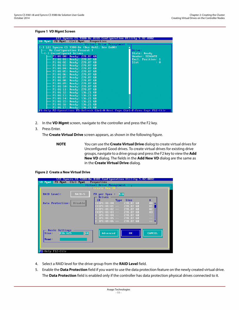
Figure 1 VD Mgmt Screen
2. In the VD Mgmt screen, navigate to the controller and press the F2 key.
3. Press Enter.
The Create Virtual Drive screen appears, as shown in the following figure.
NOTE You can use the Create Virtual Drive dialog to create virtual drives for Unconfigured Good drives. To create virtual drives for existing drive groups, navigate to a drive group and press the F2 key to view the Add New VD dialog. The fields in the Add New VD dialog are the same as in the Create Virtual Drive dialog.
Figure 2 Create a New Virtual Drive
4. Select a RAID level for the drive group from the RAID Level field.
5. Enable the Data Protection field if you want to use the data protection feature on the newly created virtual drive.
The Data Protection field is enabled only if the controller has data protection physical drives connected to it.
Avago Technologies- 12 -
Syncro CS 9361-8i and Syncro CS 9380-8e Solution User GuideOctober 2014
Chapter 2: Creating the Cluster Creating Virtual Drives on the Controller Nodes
NOTE If you use more than 32 Full Disk Encryption (FDE) drives when you create secure VDs, failover might not function for some VDs. Hence, it is best to use a maximum of 32 FDE drives when you create secure configurations.
6. You can change the sequence of the physical drives in the Drives box. All of the available unconfigured good drives appear in the Drives box. Press the spacebar to select the physical drives in the sequence that you prefer. Based on your selection, the sequence number appears in the # column.
7. You can enter a size lesser than the maximum size of the drive group, if you want to create other virtual drives on the same drive group. The maximum size of the drive group appears in the Size field. The size entered can be in MB, GB, or TB and should be mentioned only in uppercase. Before entering a size, ensure that you have deleted the previous default value by using the Backspace key.
8. Enter a name for the virtual drive in the Name field. The name given to the virtual drive cannot exceed 15 characters.
You may press the Advanced button to set additional properties for the newly created virtual drive. For more information, see Section 2.1.2, Selecting Additional Virtual Drive Properties.
9. Press OK.
A dialog appears, asking you whether you want to initialize the virtual drive you just created.
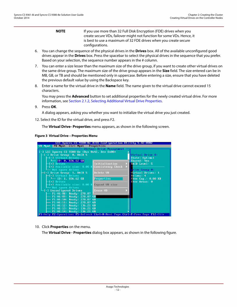
12. Select the ID for the virtual drive, and press F2.
The Virtual Drive- Properties menu appears, as shown in the following screen.
Figure 3 Virtual Drive – Properties Menu
10. Click Properties on the menu.
The Virtual Drive - Properties dialog box appears, as shown in the following figure.
Avago Technologies- 13 -
Syncro CS 9361-8i and Syncro CS 9380-8e Solution User GuideOctober 2014
Chapter 2: Creating the Cluster Creating Virtual Drives on the Controller Nodes
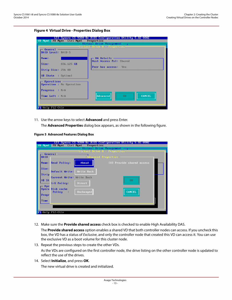
Figure 4 Virtual Drive - Properties Dialog Box
11. Use the arrow keys to select Advanced and press Enter.
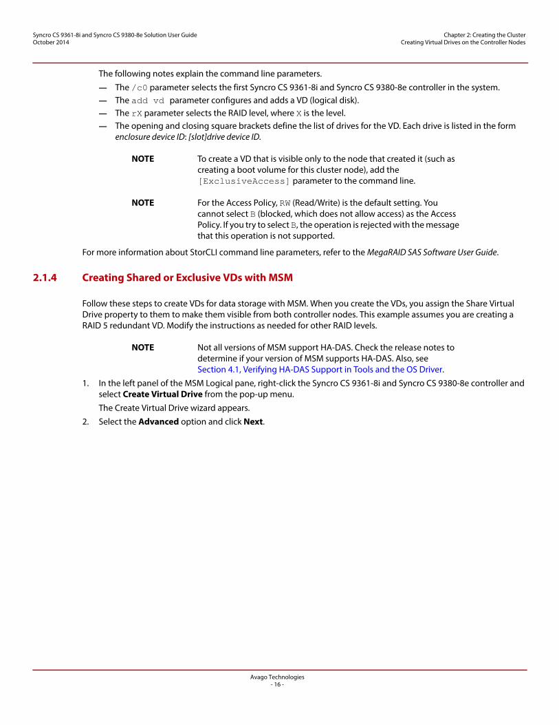
The Advanced Properties dialog box appears, as shown in the following figure.
Figure 5 Advanced Features Dialog Box
12. Make sure the Provide shared access check box is checked to enable High Availability DAS.
The Provide shared access option enables a shared VD that both controller nodes can access. If you uncheck this box, the VD has a status of Exclusive, and only the controller node that created this VD can access it. You can use the exclusive VD as a boot volume for this cluster node.
13. Repeat the previous steps to create the other VDs.
As the VDs are configured on the first controller node, the drive listing on the other controller node is updated to reflect the use of the drives.
14. Select Initialize, and press OK.
The new virtual drive is created and initialized.

Avago Technologies- 14 -
Syncro CS 9361-8i and Syncro CS 9380-8e Solution User GuideOctober 2014
Chapter 2: Creating the Cluster Creating Virtual Drives on the Controller Nodes
15. Define hot spare disks for the VDs to maximize the level of data protection.
NOTE The Syncro CS 9361-8i and Syncro CS 9380-8e solution supports global hot spares and dedicated hot spares. Global hot spares are global for the cluster, not for a controller.
16. When all VDs are configured, reboot both systems as a cluster.
2.1.2 Selecting Additional Virtual Drive Properties
This section describes the following additional virtual drive properties that you can select while you create virtual drives. Change these parameters only if you have a specific reason for doing so. It is usually best to keep them at their default settings.
Strip Size – The strip size is the portion of the stripe that resides on a single virtual drive in the drive group. Strip sizes of 64 KB, 128 KB, 256 KB, 512 KB, or 1 MB are supported.
Read Policy – Specify one of the following options to specify the read policy for this virtual drive:— Normal – Read ahead capability lets the controller read sequentially ahead of requested data and to store
the additional data in cache memory, thereby anticipating that the data will be needed soon. This process speeds up reads for sequential data, but there is little improvement when the computer accesses random data.
— Ahead – Disables the read ahead capability. Write Policy – Select one of the following options to specify the write policy for this virtual drive
— Write Thru – In this mode, the controller sends a data transfer completion signal to the host when the drive subsystem has received all the data in a transaction. This option eliminates the risk of losing cached data in case of a power failure.
— Write Back – In this mode, the controller sends a data transfer completion signal to the host when the controller cache has received all the data in a transaction.
— Write Back with BBU – In this mode the controller has no BBU or the BBU is bad. If you do not choose this option, the controller firmware automatically switches to the Write Thru mode if it detects a bad or missing BBU.
CAUTION The write policy depends on the status of the BBU. If the BBU is not present, is low, is failed, or is being charged, the virtual drive is still in the Write Back mode and there is a chance of data loss.
I/O Policy – The I/O policy applies to reads on a specific virtual drive. It does not affect the read ahead cache.— Cached – In this mode, all reads are buffered in cache memory. Cached I/O provides faster processing.— Direct – In this mode, reads are not buffered in cache memory. Data is transferred to the cache and the host
concurrently. If the same data block is read again, it comes from cache memory. Direct I/O makes sure that the cache and the host contain the same data.
Disk cache policy – Select a cache setting for this virtual drive:— Enable – Enable the drive cache.— Disable – Disable the drive cache.— Unchanged – Updating the drive cache policy to Unchanged may enable /disable the drive cache based on
the WCE (Write Cache Policy) bit of the save mode page of the drive. Initialize – Select to initialize the virtual drive. Initialization prepares the storage medium for use. Fast
initialization will be performed on the virtual drive. Configure Hot Spare – Select to configure physical drives as hot spares for the newly created virtual drive.
This option is enabled only if there are additional drives and if they are eligible to be configured as hot spares. This option is not applicable for RAID 0. If you select this option and after the Virtual drive is created, a dialog appears. The dialog asks you to choose the physical drives that you want to configure as hot spares.

Avago Technologies- 15 -
Syncro CS 9361-8i and Syncro CS 9380-8e Solution User GuideOctober 2014
Chapter 2: Creating the Cluster Creating Virtual Drives on the Controller Nodes
2.1.3 Creating Shared or Exclusive VDs with StorCLI
StorCLI is a command-line-driven utility used to create and manage VDs. StorCLI can run in any directory on the server. The following procedure assumes that a current copy of the 64-bit version of StorCLI is located on the server in a common directory as the StorCLI executable and the commands are run with administrator privileges.
1. At the command prompt, run the following command:
storcli /c0/vall show
The c0 parameter presumes that there is only one Syncro CS 9361-8i and Syncro CS 9380-8e controller in the system or that these steps reference the first Syncro CS 9361-8i and Syncro CS 9380-8e controller in a system with multiple controllers.
The following figure shows some sample configuration information that appears in response to the command.
Figure 6 Sample Configuration Information
The command generates many lines of information that scroll down in the window. You need to use some of this information to create the shared VD.
2. Find the Device ID for the JBOD enclosure for the system and the Device IDs of the available physical drives for the VD you will create.
In the second table in the preceding figure, the enclosure device ID of 252 appears under the heading EID, and the device ID of 0 appears under the heading DID. Use the scroll bar to find the device IDs for the other physical drives for the VD.
Detailed drive information, such as the drive group, capacity, and sector size, follows the device ID in the table and is explained in the text below the table.
3. Create the shared VD using the enclosure and drive device IDs with the following command line syntax:
Storcli /c0 add vd rX drives=e:s
The HA-DAS version of StorCLI creates, by default, a shared VD that is visible to all cluster nodes.
Avago Technologies- 16 -
Syncro CS 9361-8i and Syncro CS 9380-8e Solution User GuideOctober 2014
Chapter 2: Creating the Cluster Creating Virtual Drives on the Controller Nodes
The following notes explain the command line parameters.
— The /c0 parameter selects the first Syncro CS 9361-8i and Syncro CS 9380-8e controller in the system.— The add vd parameter configures and adds a VD (logical disk).— The rX parameter selects the RAID level, where X is the level.— The opening and closing square brackets define the list of drives for the VD. Each drive is listed in the form
enclosure device ID: [slot]drive device ID.
NOTE To create a VD that is visible only to the node that created it (such as creating a boot volume for this cluster node), add the [ExclusiveAccess] parameter to the command line.
NOTE For the Access Policy, RW (Read/Write) is the default setting. You cannot select B (blocked, which does not allow access) as the Access Policy. If you try to select B, the operation is rejected with the message that this operation is not supported.
For more information about StorCLI command line parameters, refer to the MegaRAID SAS Software User Guide.
2.1.4 Creating Shared or Exclusive VDs with MSM
Follow these steps to create VDs for data storage with MSM. When you create the VDs, you assign the Share Virtual Drive property to them to make them visible from both controller nodes. This example assumes you are creating a RAID 5 redundant VD. Modify the instructions as needed for other RAID levels.
NOTE Not all versions of MSM support HA-DAS. Check the release notes to determine if your version of MSM supports HA-DAS. Also, see Section 4.1, Verifying HA-DAS Support in Tools and the OS Driver.
1. In the left panel of the MSM Logical pane, right-click the Syncro CS 9361-8i and Syncro CS 9380-8e controller and select Create Virtual Drive from the pop-up menu.
The Create Virtual Drive wizard appears.
2. Select the Advanced option and click Next.

Avago Technologies- 17 -
Syncro CS 9361-8i and Syncro CS 9380-8e Solution User GuideOctober 2014
Chapter 2: Creating the Cluster Creating Virtual Drives on the Controller Nodes
3. In the next wizard screen, select RAID 5 as the RAID level, and select unconfigured drives for the VD, as shown in the following figure.
Figure 7 Drive Group Settings
4. Click Add to add the VD to the drive group.
The selected drives appear in the Drive groups window on the right.
5. Click Create Drive Group. Then click Next to continue to the next window.
The Virtual Drive Settings window appears.
6. Enter a name for the VD.
7. Select Always Write Back as the Write policy option, and select other VD settings as required.
NOTE For the Access Policy, Read Write is the default setting. You cannot select Blocked (does not allow access) as the Access Policy. If you try to select Blocked, the operation is rejected with the message that this operation is not supported.
Avago Technologies- 18 -
Syncro CS 9361-8i and Syncro CS 9380-8e Solution User GuideOctober 2014
Chapter 2: Creating the Cluster Creating Virtual Drives on the Controller Nodes
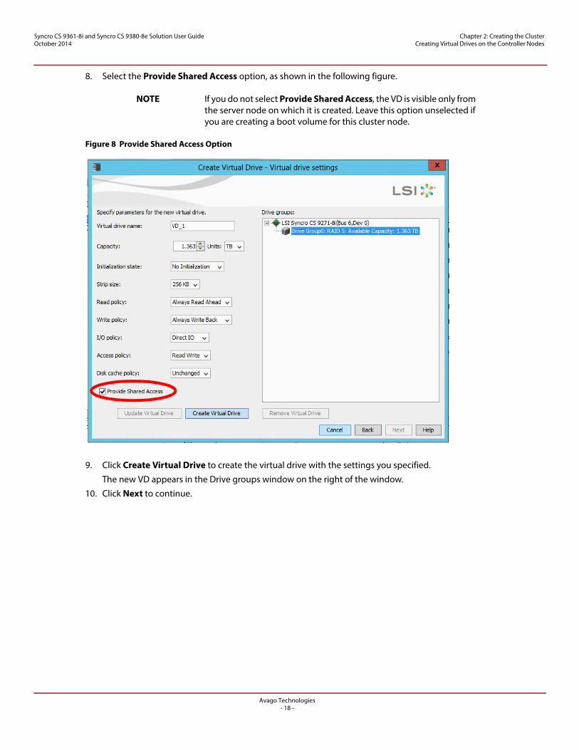
8. Select the Provide Shared Access option, as shown in the following figure.
NOTE If you do not select Provide Shared Access, the VD is visible only from the server node on which it is created. Leave this option unselected if you are creating a boot volume for this cluster node.
Figure 8 Provide Shared Access Option
9. Click Create Virtual Drive to create the virtual drive with the settings you specified.
The new VD appears in the Drive groups window on the right of the window.
10. Click Next to continue.
Avago Technologies- 19 -
Syncro CS 9361-8i and Syncro CS 9380-8e Solution User GuideOctober 2014
Chapter 2: Creating the Cluster Creating Virtual Drives on the Controller Nodes
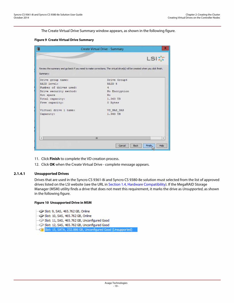
The Create Virtual Drive Summary window appears, as shown in the following figure.
Figure 9 Create Virtual Drive Summary
11. Click Finish to complete the VD creation process.
12. Click OK when the Create Virtual Drive - complete message appears.
2.1.4.1 Unsupported Drives
Drives that are used in the Syncro CS 9361-8i and Syncro CS 9380-8e solution must selected from the list of approved drives listed on the LSI website (see the URL in Section 1.4, Hardware Compatibility). If the MegaRAID Storage Manager (MSM) utility finds a drive that does not meet this requirement, it marks the drive as Unsupported, as shown in the following figure.
Figure 10 Unsupported Drive in MSM
Avago Technologies- 20 -
Syncro CS 9361-8i and Syncro CS 9380-8e Solution User GuideOctober 2014
Chapter 2: Creating the Cluster Creating the Cluster in Windows
2.2 Creating the Cluster in Windows
The following subsections describe how to enable cluster support, and how to enable and validate the failover configuration while running a Windows operating system.
2.2.1 Prerequisites for Cluster Setup
2.2.1.1 Clustered RAID Controller Support
Support for clustered RAID controllers is not enabled by default in Microsoft Windows Server 2012 or Microsoft Windows Server 2008 R2.
To enable support for this feature, please consult with your server vendor. For additional information, visit the Cluster in a Box Validation Kit for Windows Server site on the Microsoft Windows Server TechCenter website for Knowledge Base (KB) article 2839292 on enabling this support.
2.2.1.2 Enable Failover Clustering
The Microsoft Server 2012 operating system installation does not enable the clustering feature by default. Follow these steps to view the system settings, and, if necessary, to enable clustering.
1. From the desktop, launch Server Manager.
2. Click Manage and select Add Roles and Features.
3. If the Introduction box is enabled (and appears), click Next.
4. In the Select Installation Type box, select Role Based or Feature Based.
5. In the Select Destination Server box, select the system and click Next.
6. In the Select Server Roles list, click Next to present the Features list.
7. Make sure that failover clustering is installed, including the tools. If necessary, run the Add Roles and Features wizard to install the features dynamically from this user interface.
8. If the cluster nodes need to support I/O as iSCSI targets, expand File and Storage Services, File Services and check for iSCSI Target Server and Server for NFS.
During creation of the cluster, Windows automatically defines and creates the quorum, a configuration database that contains metadata required for the operation of the cluster. To create a shared VD for the quorum, see the instructions in Section 2.1, Creating Virtual Drives on the Controller Nodes.
NOTE The best practice is to create a small redundant VD for the quorum. A size of 500 MB is adequate for this purpose.
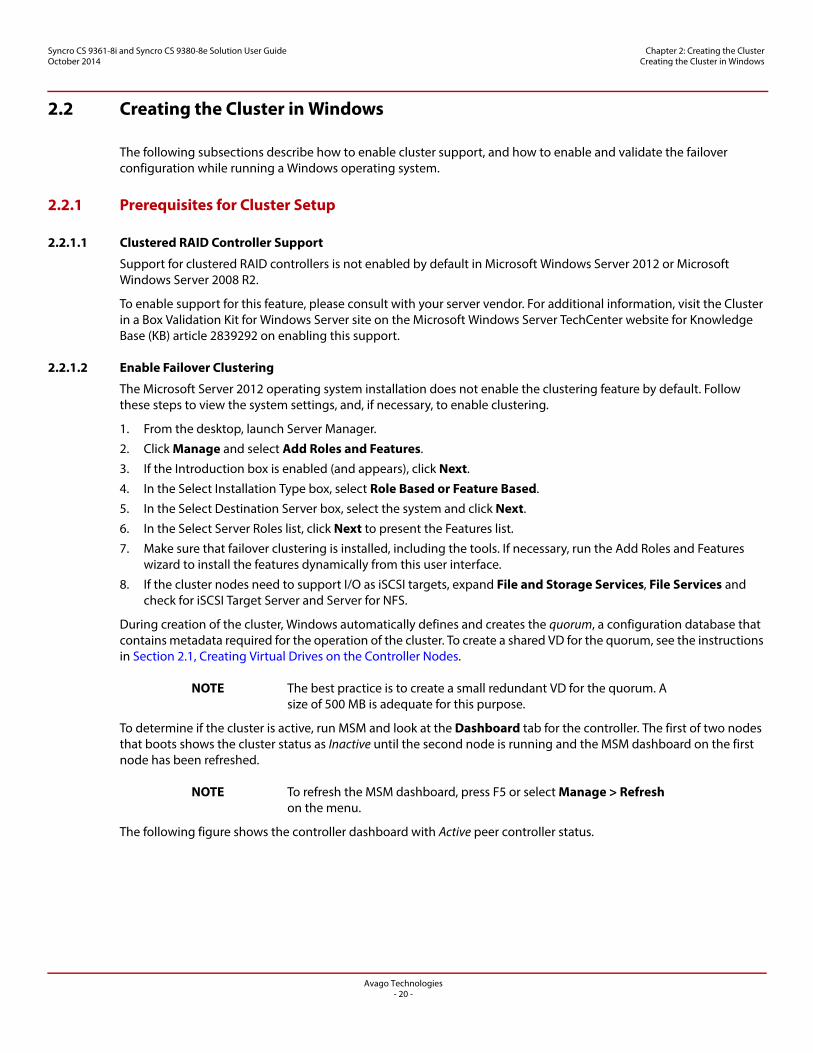
To determine if the cluster is active, run MSM and look at the Dashboard tab for the controller. The first of two nodes that boots shows the cluster status as Inactive until the second node is running and the MSM dashboard on the first node has been refreshed.
NOTE To refresh the MSM dashboard, press F5 or select Manage > Refresh on the menu.
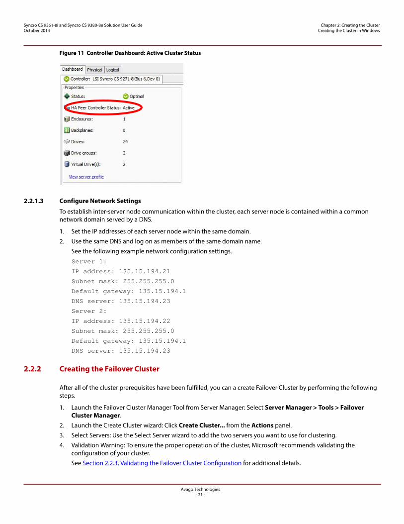
The following figure shows the controller dashboard with Active peer controller status.
Avago Technologies- 21 -
Syncro CS 9361-8i and Syncro CS 9380-8e Solution User GuideOctober 2014
Chapter 2: Creating the Cluster Creating the Cluster in Windows
Figure 11 Controller Dashboard: Active Cluster Status
2.2.1.3 Configure Network Settings
To establish inter-server node communication within the cluster, each server node is contained within a common network domain served by a DNS.
1. Set the IP addresses of each server node within the same domain.
2. Use the same DNS and log on as members of the same domain name.
See the following example network configuration settings.
Server 1:
IP address: 135.15.194.21
Subnet mask: 255.255.255.0
Default gateway: 135.15.194.1
DNS server: 135.15.194.23
Server 2:
IP address: 135.15.194.22
Subnet mask: 255.255.255.0
Default gateway: 135.15.194.1
DNS server: 135.15.194.23
2.2.2 Creating the Failover Cluster
After all of the cluster prerequisites have been fulfilled, you can a create Failover Cluster by performing the following steps.
1. Launch the Failover Cluster Manager Tool from Server Manager: Select Server Manager > Tools > Failover Cluster Manager.
2. Launch the Create Cluster wizard: Click Create Cluster... from the Actions panel.
3. Select Servers: Use the Select Server wizard to add the two servers you want to use for clustering.
4. Validation Warning: To ensure the proper operation of the cluster, Microsoft recommends validating the configuration of your cluster.
See Section 2.2.3, Validating the Failover Cluster Configuration for additional details.
Avago Technologies- 22 -
Syncro CS 9361-8i and Syncro CS 9380-8e Solution User GuideOctober 2014
Chapter 2: Creating the Cluster Creating the Cluster in Windows
5. Access Point for Administering the Cluster: Enter the name that you want to assign to the Cluster in the Cluster Name field.
6. Confirmation: A brief report containing the cluster properties appears. If no other changes are required, you have the option to specify available storage by selecting the Add all eligible Storage to the cluster check box.
7. Creating the New Cluster: Failover Cluster Manager uses the selected parameters to create the cluster.
8. Summary: A cluster creation report summary appears; this report includes any errors or warnings encountered.
9. Click on the View Report… button for additional details about the report.
2.2.3 Validating the Failover Cluster Configuration
Microsoft recommends that you validate the failover configuration before you set up failover clustering. To do this, run the Validate a Configuration wizard for Windows Server 2008 R2 or Windows Server 2012, following the instructions from Microsoft. The tests in the validation wizard include simulations of cluster actions. The tests fall into the following categories:
System Configuration tests. These tests analyze whether the two server modules meet specific requirements, such as running the same version of the operating system version using the same software updates.
Network tests. These tests analyze whether the planned cluster networks meet specific requirements, such as requirements for network redundancy.
Storage tests. These tests analyze whether the storage meets specific requirements, such as whether the storage correctly supports the required SCSI commands and handles simulated cluster actions correctly.
NOTE You can also run the Validate a Configuration wizard after you create the cluster.
Follow these steps to run the Validate a Configuration wizard.
1. In the failover cluster snap-in, in the console tree, make sure Failover Cluster Management is selected and then, under Management, click Validate a Configuration.
The Validate a Configuration wizard starts.
2. Follow the instructions for the wizard and run the tests.
Microsoft recommends that you run all available tests in the wizard.
NOTE Storage Spaces does not currently support Clustered RAID controllers. Therefore, do not include the Validate Storage Spaces Persistent Reservation storage test in the storage test suite. For additional information, visit the Cluster in a Box Validation Kit for Windows Server site on the Microsoft Windows Server TechCenter website.
3. When you arrive at the Summary page, click View Reports to view the results of the tests.
4. If any of the validation tests fails or results in a warning, correct the problems that were uncovered and run the test again.
Avago Technologies- 23 -
Syncro CS 9361-8i and Syncro CS 9380-8e Solution User GuideOctober 2014
Chapter 2: Creating the Cluster Creating the Cluster in Red Hat Enterprise Linux (RHEL) and CentOS
2.3 Creating the Cluster in Red Hat Enterprise Linux (RHEL) and CentOS
The following subsections describe how to enable cluster support, create a two-node cluster and configure NFS-clustered resources for a Red Hat operating system or a CentOS operating system.
Please note that the Syncro CS solution requires the Red Hat Enterprise Linux High Availability add-on in order for dual-active HA functionality to operate properly and ensure data integrity through fencing. Product information regarding the Red Hat Enterprise Linux High Availability add-on can be found at http://www.redhat.com/products/enterprise-linux-add-ons/high-availability/. Likewise for CentOS, you have to use the High Availability add-on from CentOS.
2.3.1 Prerequisites for Cluster Setup
Before you create a cluster, perform the following tasks so that all of the necessary modules and settings are pre-configured. Additional details regarding Red Hat High Availability Add-On configuration and management can be found at https://access.redhat.com/site/documentation/en-US/Red_Hat_Enterprise_Linux/6/pdf/Cluster_Administration/Red_Hat_Enterprise_Linux-6-Cluster_Administration-en-US.pdf.
2.3.1.1 Configure Network Settings
Perform the following steps to configure the network settings.
1. Activate the network connections for node eth0 and node eth1 by selecting the following paths:
System > Preferences > Network Connections > System eth0 > Edit > Check Connect automaticallySystem > Preferences > Network Connections > System eth1 > Edit > Check Connect automatically
2. Configure the following iptables firewall settings to allow cluster services communication:
— cman (Cluster Manager): UDP ports 5405 and 5405— dlm (Distributed Lock Manager): TCP port 21064— ricci (part of Conga remote agent): TCP port 11111— modclustered (part of Conga remote agent): TCP port 16851— luci (Conga User Interface server): TCP port 8084
2.3.1.2 Install and Configure the High Availability Add-On Features
The Syncro CS solution requires that the Red Hat Enterprise Linux High Availability add-on be applied to the base RHEL OS.
Perform the following steps to install and configure the add-on feature.
1. Install the Red Hat Cluster Resource Group Manager, Logical Volume Manager (LVM), and Global File System 2 (GFS2) utilities.
2. Update to the latest version by entering the following commands:
yum install rgmanager lvm2-cluster gfs2-utils
yum update
NOTE This step assumes that both nodes have been registered with Red Hat using the Red Hat Subscription Manager.
Avago Technologies- 24 -
Syncro CS 9361-8i and Syncro CS 9380-8e Solution User GuideOctober 2014
Chapter 2: Creating the Cluster Creating the Cluster in Red Hat Enterprise Linux (RHEL) and CentOS
2.3.1.3 Stop and Disable NetworkManager Service
You need to stop and disable NetworkManager service because the Red Hat Linux Cluster cannot work if the NetworkManager service starts. Perform the following step to stop and disable the service.
1. Enter the following command at the command line prompt:
service NetworkManager stop
2. Enter the following command at the command line prompt:
chkconfig NetworkManager off
2.3.1.4 Assign Static IP Addresses
Perform the following steps to assign static IP addresses.
1. For both nodes (a total of four IP addresses), perform these steps to set up the static IP address:
Run setup and select the path Network Configuration > Device Configuration.
2. Use the Domain Name System to enter the IP address 192.168.x.x.
3. Edit the /etc/hosts file to include the IP address and the hostname for both the node and the client.
Make sure you can ping the hostname from both the node and the client.
The following IP address, node, and client information are an example of a hosts file:
192.168.1.100 Node1
192.168.1.101 Node1
192.168.1.102 Node2
192.168.1.103 Node2
192.168.1.104 Client
2.3.1.5 Using the Ricci Service
Ricci is a daemon that runs on both server nodes and allows the cluster configuration commands to communicate with each cluster node.
1. Perform the following steps to change the ricci password for both server nodes.
a. Enter the following command at the command prompt:
passwd ricci
b. Specify your password when prompted.
2. Start the ricci service by entering the following command at the command prompt for both nodes:
service ricci start
3. (Optional) Configure the ricci service to start on boot for both nodes by entering the following command at the command prompt:
chkconfig ricci on
2.3.1.6 Starting the Luci Web Interface
Luci is a user interface server that allows you to configure the cluster using the High Availability management web interface, Conga. Perform the following steps to start the luci web interface:
Best Practice: You can run the luci web interface on either node but it is best to run it on a remote management system.
1. Enter the following command at the command prompt:
yum install luci
2. Enter the following command at the command prompt:
service luci start
Avago Technologies- 25 -
Syncro CS 9361-8i and Syncro CS 9380-8e Solution User GuideOctober 2014
Chapter 2: Creating the Cluster Creating the Cluster in Red Hat Enterprise Linux (RHEL) and CentOS
2.3.1.7 Configure SELinux
You need to configure SELinux policies to allow for clustering. Refer to Red Hat documentation to properly configure your application
2.3.2 Creating the Cluster
Configuring cluster software often occurs on a single node and is then pushed to the remaining nodes in the cluster. Multiple methods exist to configure the cluster, such as using the command line, editing configuration files directly, and using a GUI. The procedures in this document use the Conga GUI tool to configure the cluster. After the cluster is created, the following steps allow you to specify cluster resources, configure fencing, create a failover domain, and add cluster service groups.
2.3.2.1 Connect to the Luci Web Interface and Create a Cluster
Perform the following steps to connect to the luci web interface and create the cluster.
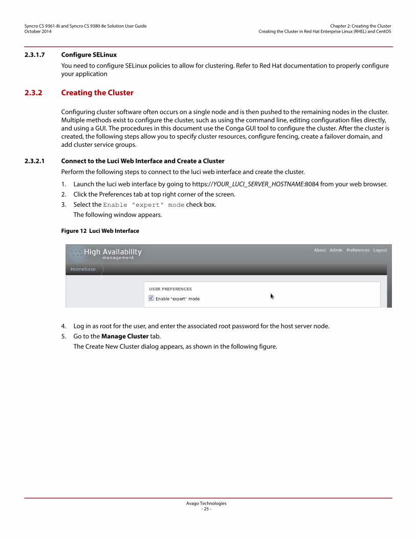
1. Launch the luci web interface by going to https://YOUR_LUCI_SERVER_HOSTNAME:8084 from your web browser.
2. Click the Preferences tab at top right corner of the screen.
3. Select the Enable "expert" mode check box.
The following window appears.
Figure 12 Luci Web Interface
4. Log in as root for the user, and enter the associated root password for the host server node.
5. Go to the Manage Cluster tab.
The Create New Cluster dialog appears, as shown in the following figure.
Avago Technologies- 26 -
Syncro CS 9361-8i and Syncro CS 9380-8e Solution User GuideOctober 2014
Chapter 2: Creating the Cluster Creating the Cluster in Red Hat Enterprise Linux (RHEL) and CentOS
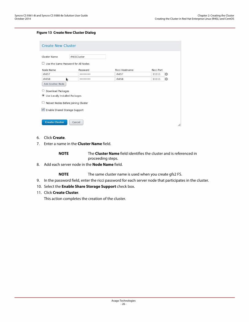
Figure 13 Create New Cluster Dialog
6. Click Create.
7. Enter a name in the Cluster Name field.
NOTE The Cluster Name field identifies the cluster and is referenced in proceeding steps.
8. Add each server node in the Node Name field.
NOTE The same cluster name is used when you create gfs2 FS.
9. In the password field, enter the ricci password for each server node that participates in the cluster.
10. Select the Enable Share Storage Support check box.
11. Click Create Cluster.
This action completes the creation of the cluster.
Avago Technologies- 27 -
Syncro CS 9361-8i and Syncro CS 9380-8e Solution User GuideOctober 2014
Chapter 2: Creating the Cluster Creating the Cluster in Red Hat Enterprise Linux (RHEL) and CentOS
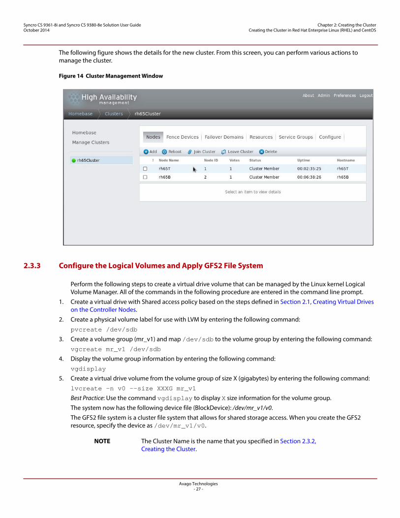
The following figure shows the details for the new cluster. From this screen, you can perform various actions to manage the cluster.
Figure 14 Cluster Management Window
2.3.3 Configure the Logical Volumes and Apply GFS2 File System
Perform the following steps to create a virtual drive volume that can be managed by the Linux kernel Logical Volume Manager. All of the commands in the following procedure are entered in the command line prompt.
1. Create a virtual drive with Shared access policy based on the steps defined in Section 2.1, Creating Virtual Drives on the Controller Nodes.
2. Create a physical volume label for use with LVM by entering the following command:
pvcreate /dev/sdb
3. Create a volume group (mr_v1) and map /dev/sdb to the volume group by entering the following command:
vgcreate mr_v1 /dev/sdb
4. Display the volume group information by entering the following command:
vgdisplay
5. Create a virtual drive volume from the volume group of size X (gigabytes) by entering the following command:
lvcreate -n v0 --size XXXG mr_v1
Best Practice: Use the command vgdisplay to display X size information for the volume group.
The system now has the following device file (BlockDevice): /dev/mr_v1/v0.
The GFS2 file system is a cluster file system that allows for shared storage access. When you create the GFS2 resource, specify the device as /dev/mr_v1/v0.
NOTE The Cluster Name is the name that you specified in Section 2.3.2, Creating the Cluster.
Avago Technologies- 28 -
Syncro CS 9361-8i and Syncro CS 9380-8e Solution User GuideOctober 2014
Chapter 2: Creating the Cluster Creating the Cluster in Red Hat Enterprise Linux (RHEL) and CentOS
2.3.3.1 Create a GFS2 File System
The GFS2 file system is a cluster file system that allows for shared storage access.
Perform the following steps to create a GFS2 file system.
1. To apply this file system to the virtual drives created in the previous procedure, enter the following command:
mkfs.gfs2 -p lock_dlm -t ClusterName:FSName -j NumberJournals BlockDevice
For example, using the virtual drive created in the previous step, the result is as follows:
mkfs.gfs2 -p lock_dlm -t YOUR_CLUSTER_NAME:V1 -j 3 /dev/mr_v1/v0.
2. Create mount points from each server node.
For example, you can create a mount point by entering the following command:
/root/mnt/vol1.
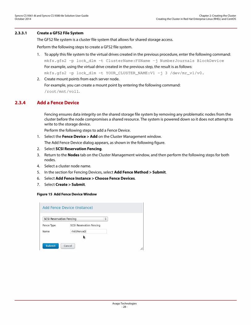
2.3.4 Add a Fence Device
Fencing ensures data integrity on the shared storage file system by removing any problematic nodes from the cluster before the node compromises a shared resource. The system is powered down so it does not attempt to write to the storage device.
Perform the following steps to add a Fence Device.
1. Select the Fence Device > Add on the Cluster Management window.
The Add Fence Device dialog appears, as shown in the following figure.
2. Select SCSI Reservation Fencing.
3. Return to the Nodes tab on the Cluster Management window, and then perform the following steps for both nodes.
4. Select a cluster node name.
5. In the section for Fencing Devices, select Add Fence Method > Submit.
6. Select Add Fence Instance > Choose Fence Devices.
7. Select Create > Submit.
Figure 15 Add Fence Device Window
Avago Technologies- 29 -
Syncro CS 9361-8i and Syncro CS 9380-8e Solution User GuideOctober 2014
Chapter 2: Creating the Cluster Creating the Cluster in Red Hat Enterprise Linux (RHEL) and CentOS
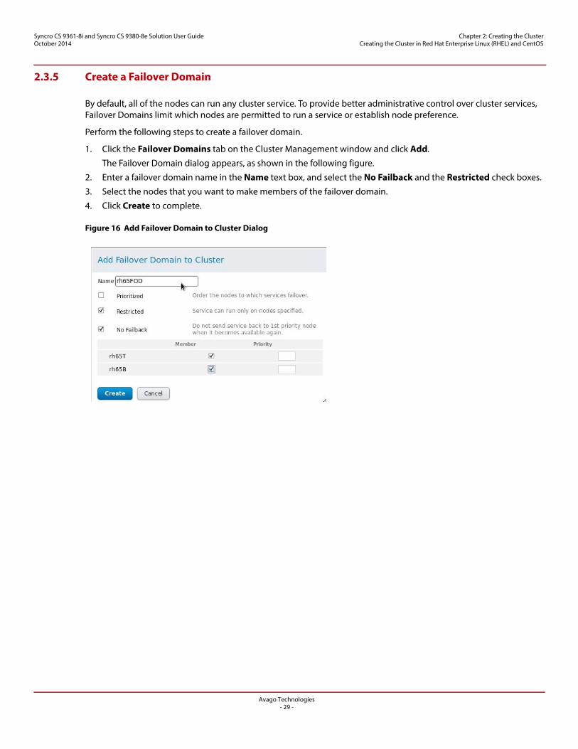
2.3.5 Create a Failover Domain
By default, all of the nodes can run any cluster service. To provide better administrative control over cluster services, Failover Domains limit which nodes are permitted to run a service or establish node preference.
Perform the following steps to create a failover domain.
1. Click the Failover Domains tab on the Cluster Management window and click Add.
The Failover Domain dialog appears, as shown in the following figure.
2. Enter a failover domain name in the Name text box, and select the No Failback and the Restricted check boxes.
3. Select the nodes that you want to make members of the failover domain.
4. Click Create to complete.
Figure 16 Add Failover Domain to Cluster Dialog
Avago Technologies- 30 -
Syncro CS 9361-8i and Syncro CS 9380-8e Solution User GuideOctober 2014
Chapter 2: Creating the Cluster Creating the Cluster in Red Hat Enterprise Linux (RHEL) and CentOS
2.3.6 Add Resources to the Cluster
Shared resources can be shared directories or properties, such as the IP address, that are tied to the cluster. These resources can be referenced by clients as though the cluster were a single server/entity. This section describes how to add GFS2 and IP address cluster resources.
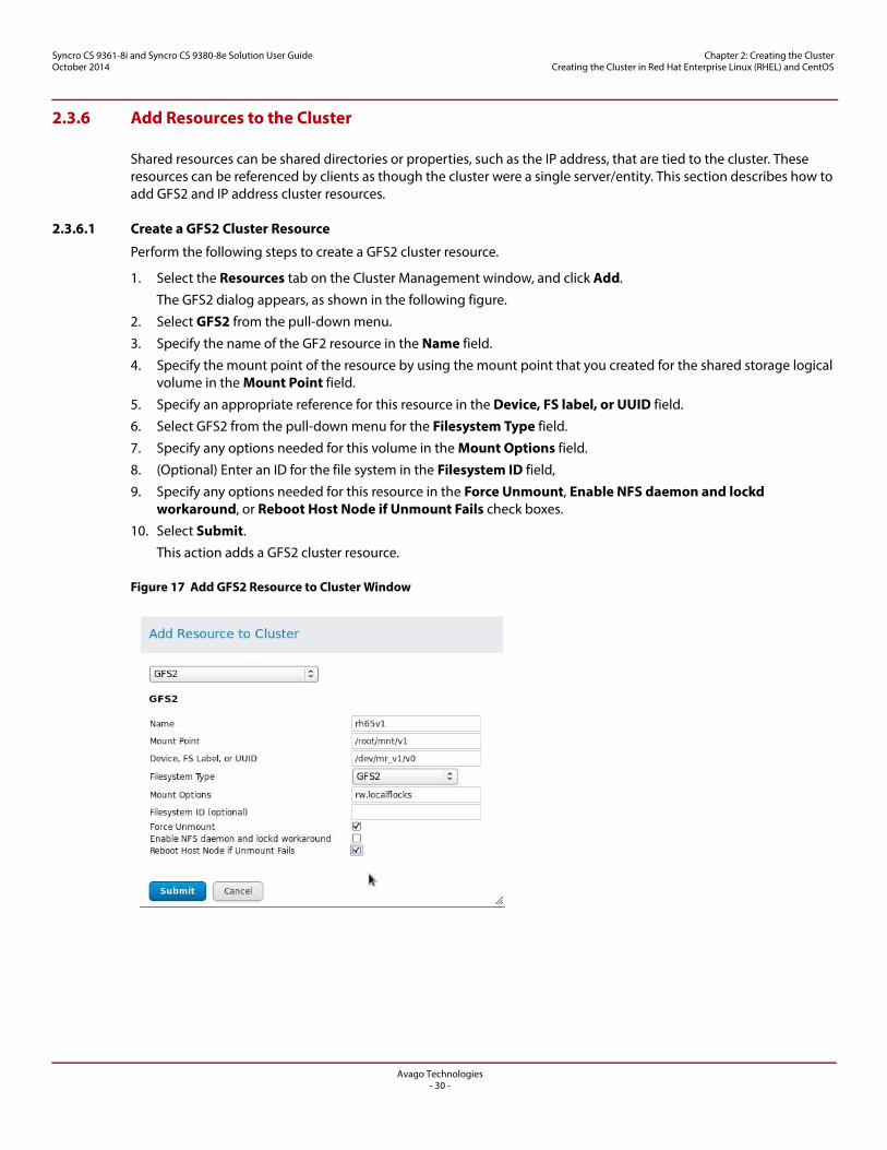
2.3.6.1 Create a GFS2 Cluster Resource
Perform the following steps to create a GFS2 cluster resource.
1. Select the Resources tab on the Cluster Management window, and click Add.
The GFS2 dialog appears, as shown in the following figure.
2. Select GFS2 from the pull-down menu.
3. Specify the name of the GF2 resource in the Name field.
4. Specify the mount point of the resource by using the mount point that you created for the shared storage logical volume in the Mount Point field.
5. Specify an appropriate reference for this resource in the Device, FS label, or UUID field.
6. Select GFS2 from the pull-down menu for the Filesystem Type field.
7. Specify any options needed for this volume in the Mount Options field.
8. (Optional) Enter an ID for the file system in the Filesystem ID field,
9. Specify any options needed for this resource in the Force Unmount, Enable NFS daemon and lockd workaround, or Reboot Host Node if Unmount Fails check boxes.
10. Select Submit.
This action adds a GFS2 cluster resource.
Figure 17 Add GFS2 Resource to Cluster Window
Avago Technologies- 31 -
Syncro CS 9361-8i and Syncro CS 9380-8e Solution User GuideOctober 2014
Chapter 2: Creating the Cluster Creating the Cluster in Red Hat Enterprise Linux (RHEL) and CentOS
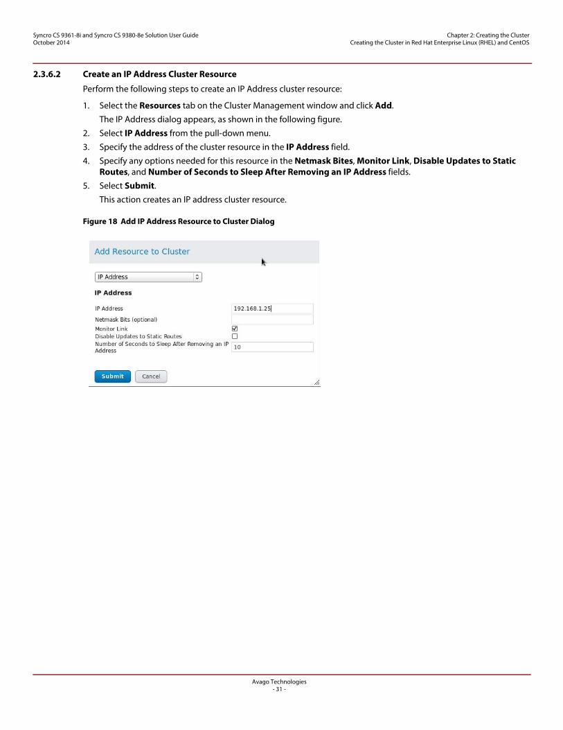
2.3.6.2 Create an IP Address Cluster Resource
Perform the following steps to create an IP Address cluster resource:
1. Select the Resources tab on the Cluster Management window and click Add.
The IP Address dialog appears, as shown in the following figure.
2. Select IP Address from the pull-down menu.
3. Specify the address of the cluster resource in the IP Address field.
4. Specify any options needed for this resource in the Netmask Bites, Monitor Link, Disable Updates to Static Routes, and Number of Seconds to Sleep After Removing an IP Address fields.
5. Select Submit.
This action creates an IP address cluster resource.
Figure 18 Add IP Address Resource to Cluster Dialog
Avago Technologies- 32 -
Syncro CS 9361-8i and Syncro CS 9380-8e Solution User GuideOctober 2014
Chapter 2: Creating the Cluster Creating the Cluster in Red Hat Enterprise Linux (RHEL) and CentOS
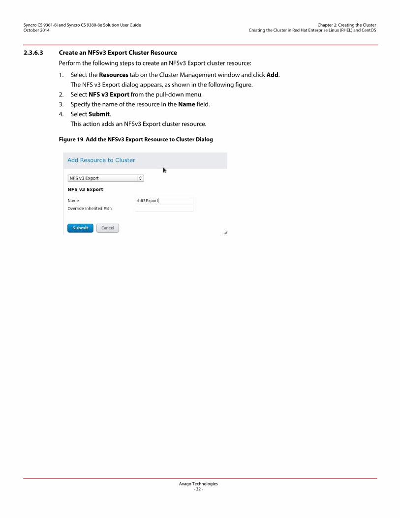
2.3.6.3 Create an NFSv3 Export Cluster Resource
Perform the following steps to create an NFSv3 Export cluster resource:
1. Select the Resources tab on the Cluster Management window and click Add.
The NFS v3 Export dialog appears, as shown in the following figure.
2. Select NFS v3 Export from the pull-down menu.
3. Specify the name of the resource in the Name field.
4. Select Submit.
This action adds an NFSv3 Export cluster resource.
Figure 19 Add the NFSv3 Export Resource to Cluster Dialog
Avago Technologies- 33 -
Syncro CS 9361-8i and Syncro CS 9380-8e Solution User GuideOctober 2014
Chapter 2: Creating the Cluster Creating the Cluster in Red Hat Enterprise Linux (RHEL) and CentOS
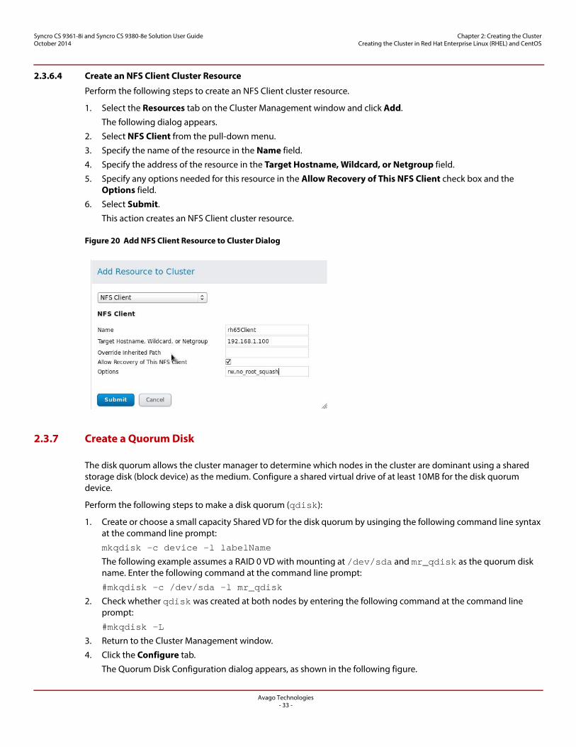
2.3.6.4 Create an NFS Client Cluster Resource
Perform the following steps to create an NFS Client cluster resource.
1. Select the Resources tab on the Cluster Management window and click Add.
The following dialog appears.
2. Select NFS Client from the pull-down menu.
3. Specify the name of the resource in the Name field.
4. Specify the address of the resource in the Target Hostname, Wildcard, or Netgroup field.
5. Specify any options needed for this resource in the Allow Recovery of This NFS Client check box and the Options field.
6. Select Submit.
This action creates an NFS Client cluster resource.
Figure 20 Add NFS Client Resource to Cluster Dialog
2.3.7 Create a Quorum Disk
The disk quorum allows the cluster manager to determine which nodes in the cluster are dominant using a shared storage disk (block device) as the medium. Configure a shared virtual drive of at least 10MB for the disk quorum device.
Perform the following steps to make a disk quorum (qdisk):
1. Create or choose a small capacity Shared VD for the disk quorum by usinging the following command line syntax at the command line prompt:
mkqdisk -c device -l labelName
The following example assumes a RAID 0 VD with mounting at /dev/sda and mr_qdisk as the quorum disk name. Enter the following command at the command line prompt:
#mkqdisk -c /dev/sda -l mr_qdisk
2. Check whether qdisk was created at both nodes by entering the following command at the command line prompt:
#mkqdisk -L
3. Return to the Cluster Management window.
4. Click the Configure tab.
The Quorum Disk Configuration dialog appears, as shown in the following figure.
Avago Technologies- 34 -
Syncro CS 9361-8i and Syncro CS 9380-8e Solution User GuideOctober 2014
Chapter 2: Creating the Cluster Creating the Cluster in Red Hat Enterprise Linux (RHEL) and CentOS
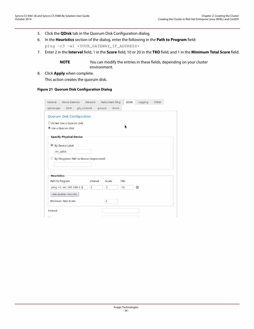
5. Click the QDisk tab in the Quorum Disk Configuration dialog.
6. In the Heuristics section of the dialog, enter the following in the Path to Program field:
ping -c3 -w1 <YOUR_GATEWAY_IP_ADDRESS>
7. Enter 2 in the Interval field, 1 in the Score field, 10 or 20 in the TKO field, and 1 in the Minimum Total Score field.
NOTE You can modify the entries in these fields, depending on your cluster environment.
8. Click Apply when complete.
This action creates the quorum disk.
Figure 21 Quorum Disk Configuration Dialog
Avago Technologies- 35 -
Syncro CS 9361-8i and Syncro CS 9380-8e Solution User GuideOctober 2014
Chapter 2: Creating the Cluster Creating the Cluster in Red Hat Enterprise Linux (RHEL) and CentOS
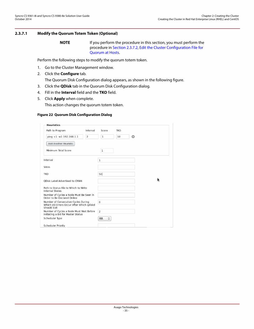
2.3.7.1 Modify the Quorum Totem Token (Optional)
NOTE If you perform the procedure in this section, you must perform the procedure in Section 2.3.7.2, Edit the Cluster Configuration File for Quorum at Hosts.
Perform the following steps to modify the quorum totem token.
1. Go to the Cluster Management window.
2. Click the Configure tab.
The Quorum Disk Configuration dialog appears, as shown in the following figure.
3. Click the QDisk tab in the Quorum Disk Configuration dialog.
4. Fill in the Interval field and the TKO field.
5. Click Apply when complete.
This action changes the quorum totem token.
Figure 22 Quorum Disk Configuration Dialog
Avago Technologies- 36 -
Syncro CS 9361-8i and Syncro CS 9380-8e Solution User GuideOctober 2014
Chapter 2: Creating the Cluster Creating the Cluster in Red Hat Enterprise Linux (RHEL) and CentOS
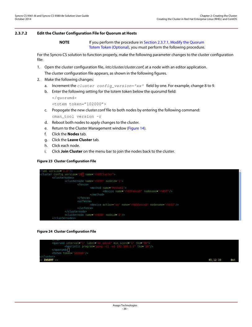
2.3.7.2 Edit the Cluster Configuration File for Quorum at Hosts
NOTE If you perform the procedure in Section 2.3.7.1, Modify the Quorum Totem Token (Optional), you must perform the following procedure.
For the Syncro CS solution to function properly, make the following parameter changes to the cluster configuration file:
1. Open the cluster configuration file, /etc/cluster/cluster.conf, at a node with an editor application.
The cluster configuration file appears, as shown in the following figures.
2. Make the following changes:
a. Increment the cluster config_version="xx" field by one. For example, change 8 to 9. b. Enter the following setting for the totem token below the quorumd field:
</quorumd>
<totem token=”102000”>
c. Propogate the new cluster.conf file to both nodes by entering the following command:
cman_tool version -r
d. Reboot both nodes to apply changes to the cluster.e. Return to the Cluster Management window (Figure 14).f. Click the Nodes tab.g. Click the Leave Cluster tab.h. Click each node.i. Click Join Cluster on the menu bar to join the nodes back to the cluster.
Figure 23 Cluster Configuration File
Figure 24 Cluster Configuration File
Avago Technologies- 37 -
Syncro CS 9361-8i and Syncro CS 9380-8e Solution User GuideOctober 2014
Chapter 2: Creating the Cluster Creating the Cluster in Red Hat Enterprise Linux (RHEL) and CentOS
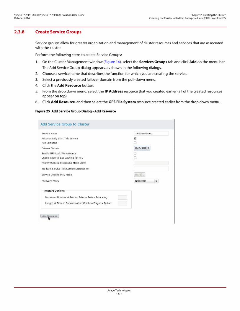
2.3.8 Create Service Groups
Service groups allow for greater organization and management of cluster resources and services that are associated with the cluster.
Perform the following steps to create Service Groups:
1. On the Cluster Management window (Figure 14), select the Services Groups tab and click Add on the menu bar.
The Add Service Group dialog appears, as shown in the following dialogs.
2. Choose a service name that describes the function for which you are creating the service.
3. Select a previously created failover domain from the pull-down menu.
4. Click the Add Resource button.
5. From the drop down menu, select the IP Address resource that you created earlier (all of the created resources appear on top).
6. Click Add Resource, and then select the GFS File System resource created earlier from the drop down menu.
Figure 25 Add Service Group Dialog - Add Resource
Avago Technologies- 38 -
Syncro CS 9361-8i and Syncro CS 9380-8e Solution User GuideOctober 2014
Chapter 2: Creating the Cluster Creating the Cluster in Red Hat Enterprise Linux (RHEL) and CentOS
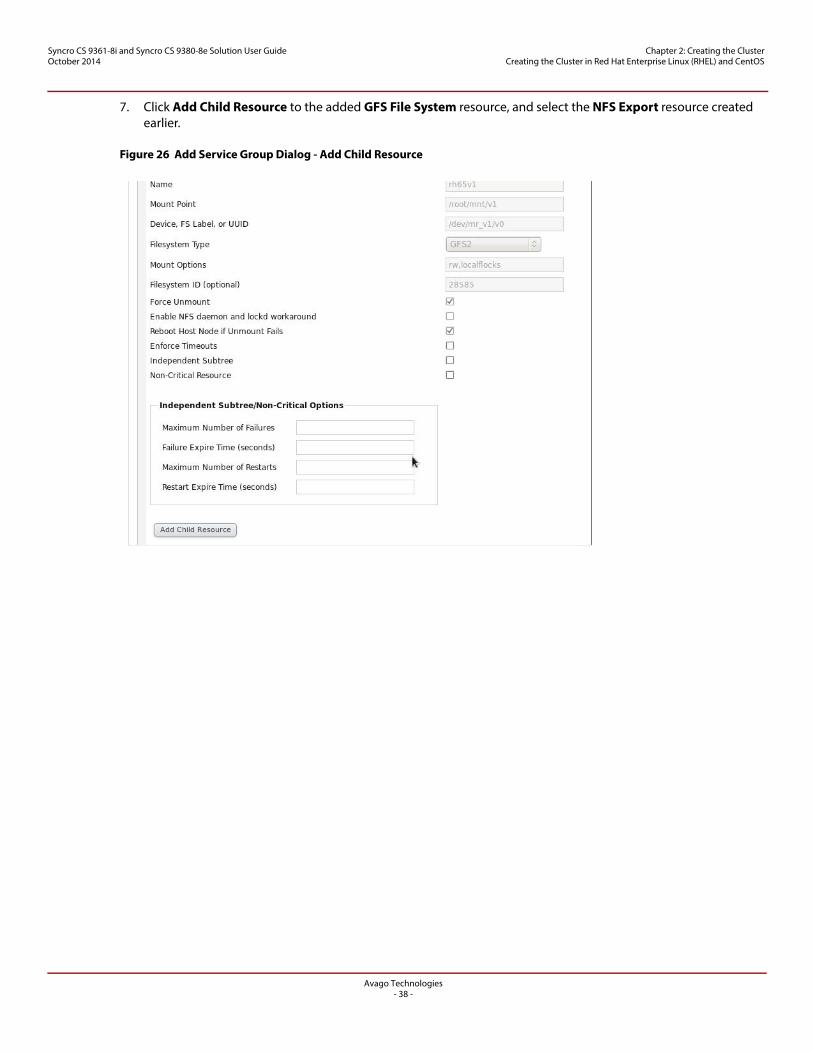
7. Click Add Child Resource to the added GFS File System resource, and select the NFS Export resource created earlier.
Figure 26 Add Service Group Dialog - Add Child Resource
Avago Technologies- 39 -
Syncro CS 9361-8i and Syncro CS 9380-8e Solution User GuideOctober 2014
Chapter 2: Creating the Cluster Creating the Cluster in SuSE Linux Enterprise Server (SLES)
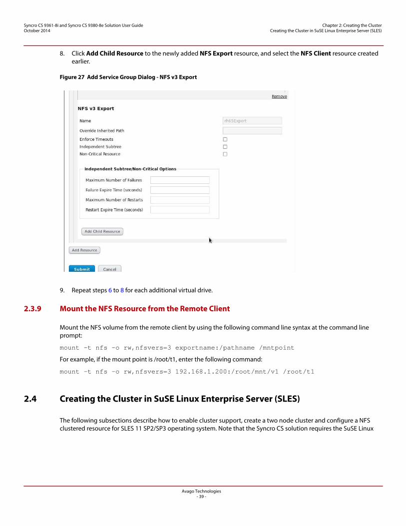
8. Click Add Child Resource to the newly added NFS Export resource, and select the NFS Client resource created earlier.
Figure 27 Add Service Group Dialog - NFS v3 Export
9. Repeat steps 6 to 8 for each additional virtual drive.
2.3.9 Mount the NFS Resource from the Remote Client
Mount the NFS volume from the remote client by using the following command line syntax at the command line prompt:
mount –t nfs –o rw,nfsvers=3 exportname:/pathname /mntpoint
For example, if the mount point is /root/t1, enter the following command:
mount -t nfs -o rw,nfsvers=3 192.168.1.200:/root/mnt/v1 /root/t1
2.4 Creating the Cluster in SuSE Linux Enterprise Server (SLES)
The following subsections describe how to enable cluster support, create a two node cluster and configure a NFS clustered resource for SLES 11 SP2/SP3 operating system. Note that the Syncro CS solution requires the SuSE Linux
Avago Technologies- 40 -
Syncro CS 9361-8i and Syncro CS 9380-8e Solution User GuideOctober 2014
Chapter 2: Creating the Cluster Creating the Cluster in SuSE Linux Enterprise Server (SLES)
Enterprise High Availability (SLE-HA) extensions in order to operate properly. Additional product details regarding SuSE High Availability Extensions can be found at https://www.suse.com/products/highavailability/.
2.4.1 Prerequisites for Cluster Setup
Before you create a cluster, you need to perform the following tasks to ensure that all of the necessary modules and settings are pre-configured.
2.4.1.1 Prepare the Operating System
Perform the following steps to prepare the operating system:
1. Make sure that all of the maintenance updates for the SLES 11 Service Pack 2/3 are installed.
2. Install the SLE-HA extension by performing the following steps.
a. Download the SLE-HA Extension iso to each node.b. To install this SLE-HA add-on, start YaST and select Software > Add-On Products.c. Select the local ISO image, and then enter the path to ISO Image.d. From the filter list, select Patterns, and activate the High Availability pattern in the pattern list.e. Click Accept to start installing the packages.f. Install the High Availability pattern on node 2 that is part of the cluster.
2.4.1.2 Configure Network Settings
Each node should have two Ethernet ports, with one (em1) connected to the network switch, and another (em2) connected to the em2 ethernet port on the other node.
Perform the following steps to configure network settings:
1. Perform the following steps to assign the static IP addresses:
a. In each node, set up the static IP address for both em1 and em2 ethernet ports by selecting Application > yast > Network settings.
b. Select the ethernet port em1, and then select Edit. c. Select the statically assigned IP address, input the IP Address/ Subnet Mask / Hostname, and then confirm the
changes.d. Repeat steps b and c for ethernet port em2.
2. You need to open the following ports for each node in the firewall for communication of cluster services between nodes:
— TCP Ports – 30865, 5560, 7630, 21064— UDP Port – 5405
3. Create the file /etc/sysconfig/network/routes, and enter the following text:
default YOUR_GATEWAY_IPADDRESS - -
4. Edit the file /etc/resolv.conf to change the DNS IP address to the IP address of the DNS server in your network in the following format:
nameserver YOUR_DNS_IPADDRESS
Alternatively, you can set the DNS and Default gateway in the Network Settings screen Global Options tab, Host/DNS tab, or Routing tab, as shown in the following figures.
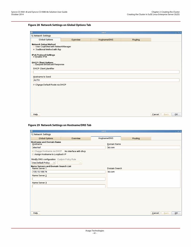
Avago Technologies- 41 -
Syncro CS 9361-8i and Syncro CS 9380-8e Solution User GuideOctober 2014
Chapter 2: Creating the Cluster Creating the Cluster in SuSE Linux Enterprise Server (SLES)
Figure 28 Network Settings on Global Options Tab
Figure 29 Network Settings on Hostname/DNS Tab
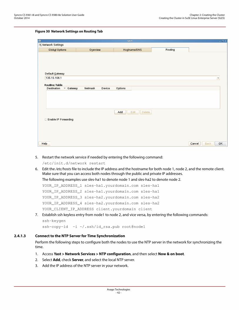
Avago Technologies- 42 -
Syncro CS 9361-8i and Syncro CS 9380-8e Solution User GuideOctober 2014
Chapter 2: Creating the Cluster Creating the Cluster in SuSE Linux Enterprise Server (SLES)
Figure 30 Network Settings on Routing Tab
5. Restart the network service if needed by entering the following command:
/etc/init.d/network restart
6. Edit the /etc/hosts file to include the IP address and the hostname for both node 1, node 2, and the remote client. Make sure that you can access both nodes through the public and private IP addresses.
The following examples use sles-ha1 to denote node 1 and sles-ha2 to denote node 2.
YOUR_IP_ADDRESS_1 sles-ha1.yourdomain.com sles-ha1
YOUR_IP_ADDRESS_2 sles-ha1.yourdomain.com sles-ha1
YOUR_IP_ADDRESS_3 sles-ha2.yourdomain.com sles-ha2
YOUR_IP_ADDRESS_4 sles-ha2.yourdomain.com sles-ha2
YOUR_CLIENT_IP_ADDRESS client.yourdomain client
7. Establish ssh keyless entry from node1 to node 2, and vice versa, by entering the following commands:
ssh-keygen
ssh-copy-id -i ~/.ssh/id_rsa.pub root@node1
2.4.1.3 Connect to the NTP Server for Time Synchronization
Perform the following steps to configure both the nodes to use the NTP server in the network for synchronizing the time.
1. Access Yast > Network Services > NTP configuration, and then select Now & on boot.
2. Select Add, check Server, and select the local NTP server.
3. Add the IP address of the NTP server in your network.
Avago Technologies- 43 -
Syncro CS 9361-8i and Syncro CS 9380-8e Solution User GuideOctober 2014
Chapter 2: Creating the Cluster Creating the Cluster in SuSE Linux Enterprise Server (SLES)
2.4.2 Creating the Cluster
You can use multiple methods to configure the cluster directly, such as using the command line, editing configuration files, and using a GUI. The procedures in this document use a combination of the Yast GUI tool and the command line to configure the cluster. After the cluster is online, you can perform the following steps to add NFS cluster resources.
2.4.2.1 Cluster Setup
Perform the following step to install the cluster setup automatically.
1. On node1, start the bootstrap script by entering the following command:
sleha-init
NOTE If NTP is not configured on the nodes, a warning appears. You can address the warning by configuring NTP by following the steps in Section 2.4.1.3, Connect to the NTP Server for Time Synchronization.
2. Specify the Worldwide Identifier (WWID) for a shared virtual drive in your node when prompted.
The following WWID is shown as an example.
/dev/disk/by-id/wwn-0x600605b00316386019265c4910e9a343
3. On Node 2, start the bootstrap script by entering the following command.
sleha-join
4. Complete the cluster setup on node 2 by specifying the Worldwide Identifier (WWID) for a shared virtual drive in your node when prompted.
After you perform the initial cluster setup using the bootstrap scripts, you need to make changes to the cluster settings that you could not make during bootstrap.
Perform the following steps to revise the cluster Communication Channels, Security, Service, Csync2 and conntrackd settings.
1. Start the cluster module from command line by entering the following command.
yast2 cluster
2. After the fields in the following screen display the information (according to your setup), click the check box next to the Auto Generate Node ID field to automatically generate a unique ID for every cluster node.
3. If you modified any options for an existing cluster, confirm your changes, and close the cluster module. YaST writes the configuration to /etc/corosync/corosync.conf.
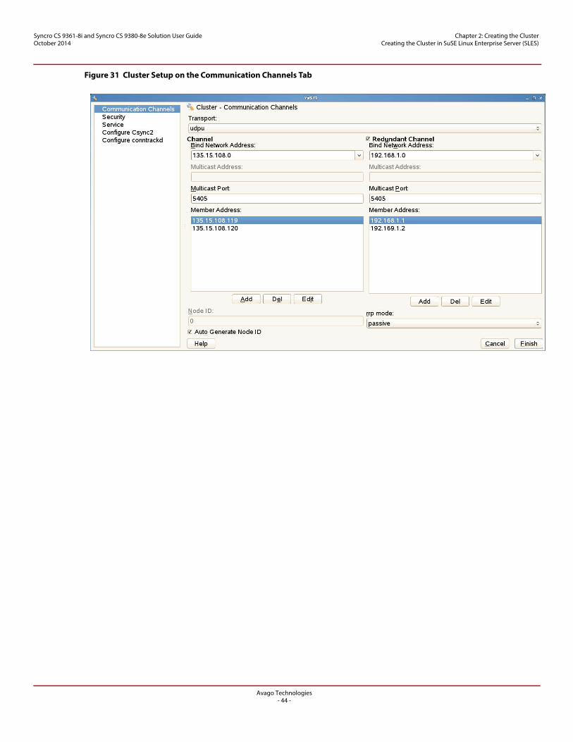
Avago Technologies- 44 -
Syncro CS 9361-8i and Syncro CS 9380-8e Solution User GuideOctober 2014
Chapter 2: Creating the Cluster Creating the Cluster in SuSE Linux Enterprise Server (SLES)
Figure 31 Cluster Setup on the Communication Channels Tab
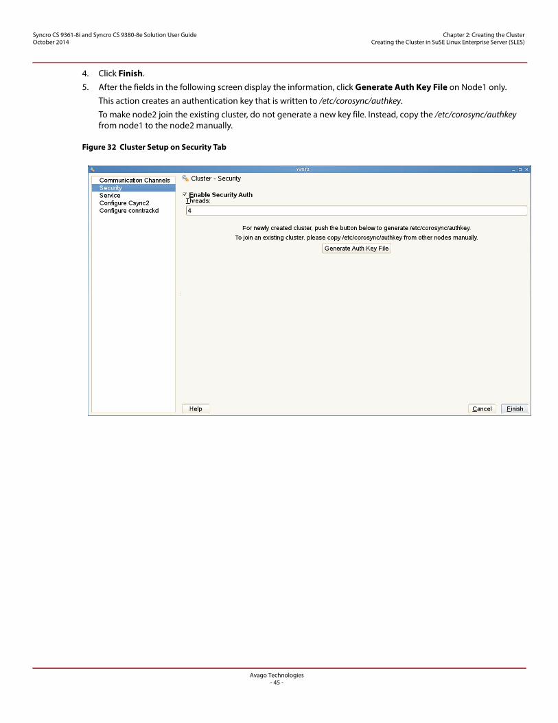
Avago Technologies- 45 -
Syncro CS 9361-8i and Syncro CS 9380-8e Solution User GuideOctober 2014
Chapter 2: Creating the Cluster Creating the Cluster in SuSE Linux Enterprise Server (SLES)
4. Click Finish.
5. After the fields in the following screen display the information, click Generate Auth Key File on Node1 only.
This action creates an authentication key that is written to /etc/corosync/authkey.
To make node2 join the existing cluster, do not generate a new key file. Instead, copy the /etc/corosync/authkey from node1 to the node2 manually.
Figure 32 Cluster Setup on Security Tab
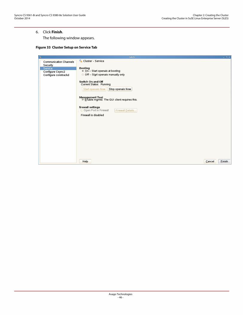
Avago Technologies- 46 -
Syncro CS 9361-8i and Syncro CS 9380-8e Solution User GuideOctober 2014
Chapter 2: Creating the Cluster Creating the Cluster in SuSE Linux Enterprise Server (SLES)
6. Click Finish.
The following window appears.
Figure 33 Cluster Setup on Service Tab
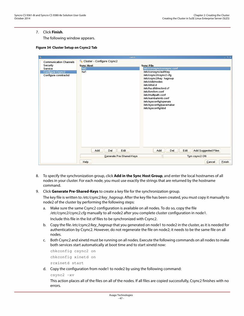
Avago Technologies- 47 -
Syncro CS 9361-8i and Syncro CS 9380-8e Solution User GuideOctober 2014
Chapter 2: Creating the Cluster Creating the Cluster in SuSE Linux Enterprise Server (SLES)
7. Click Finish.
The following window appears.
Figure 34 Cluster Setup on Csync2 Tab
8. To specify the synchronization group, click Add in the Sync Host Group, and enter the local hostnames of all nodes in your cluster. For each node, you must use exactly the strings that are returned by the hostname command.
9. Click Generate Pre-Shared-Keys to create a key file for the synchronization group.
The key file is written to /etc/csync2/key_hagroup. After the key file has been created, you must copy it manually to node2 of the cluster by performing the following steps:
a. Make sure the same Csync2 configuration is available on all nodes. To do so, copy the file /etc/csync2/csync2.cfg manually to all node2 after you complete cluster configuration in node1.
Include this file in the list of files to be synchronized with Csync2.
b. Copy the file /etc/csync2/key_hagroup that you generated on node1 to node2 in the cluster, as it is needed for authentication by Csync2. However, do not regenerate the file on node2; it needs to be the same file on all nodes.
c. Both Csync2 and xinetd must be running on all nodes. Execute the following commands on all nodes to make both services start automatically at boot time and to start xinetd now:
chkconfig csync2 on
chkconfig xinetd on
rcxinetd start
d. Copy the configuration from node1 to node2 by using the following command:
csync2 -xv
This action places all of the files on all of the nodes. If all files are copied successfully, Csync2 finishes with no errors.
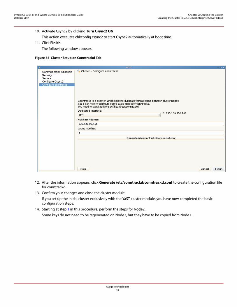
Avago Technologies- 48 -
Syncro CS 9361-8i and Syncro CS 9380-8e Solution User GuideOctober 2014
Chapter 2: Creating the Cluster Creating the Cluster in SuSE Linux Enterprise Server (SLES)
10. Activate Csync2 by clicking Turn Csync2 ON.
This action executes chkconfig csync2 to start Csync2 automatically at boot time.
11. Click Finish.
The following window appears.
Figure 35 Cluster Setup on Conntrackd Tab
12. After the information appears, click Generate /etc/conntrackd/conntrackd.conf to create the configuration file for conntrackd.
13. Confirm your changes and close the cluster module.
If you set up the initial cluster exclusively with the YaST cluster module, you have now completed the basic configuration steps.
14. Starting at step 1 in this procedure, perform the steps for Node2.
Some keys do not need to be regenerated on Node2, but they have to be copied from Node1.
Avago Technologies- 49 -
Syncro CS 9361-8i and Syncro CS 9380-8e Solution User GuideOctober 2014
Chapter 2: Creating the Cluster Creating the Cluster in SuSE Linux Enterprise Server (SLES)
2.4.3 Bringing the Cluster Online
Perform the following steps to bring the cluster online.
1. Check if the openais service is already running by entering the following command at the command prompt:
rcopenais status
2. If the openais service is already running, go to step 3. If not, start OpenAIS/Corosync now by entering the following command at the command prompt:
rcopenais start
3. Repeat the steps above for each of the cluster nodes. On each of the nodes, check the cluster status with the following command:
crm_mon
If all of the nodes are online, the output should be similar to the following:
============
Last updated: Thu May 23 04:28:26 2013
Last change: Mon May 20 09:05:29 2013 by hacluster via crmd on sles-ha1
Stack: openais
Current DC: sles-ha2 - partition with quorum
Version: 1.1.6-b988976485d15cb702c9307df55512d323831a5e
2 Nodes configured, 2 expected votes
1 Resources configured.
Online: [ sles-ha2 sles-ha1 ]
stonith-sbd (stonith:external/sbd): Started sles-ha2
============
This output indicates that the cluster resource manager is started and is ready to manage resources.
2.4.4 Configuring the NFS Resource with STONITH SBD Fencing
The following subsections describe how to set up an NFS resource by installing the NFS kernel server, configuring the shared VD by partitioning, applying the ext3 file system, and configuring the stonith_sbd fencing.
2.4.4.1 Install NFSSERVER
Use Yast to install nfs-kernel-server and all of the required dependencies.
2.4.4.2 Configure the Partition and the File System
Perform the following steps to configure the partition and the file system.
1. Use fdisk or any other partition modification tool to create partitions on the virtual drive.
For this example, /dev/sda is on a shared virtual drive with two partitions created: sda1 (part1) for sbd and sda2 (part2) for NFS mount (the actual data sharing partition)
2. Use mkfs to apply the ext3 file system to the partition(s)/
sles-ha1:~ # mkfs.ext3 /dev/sda1
sles-ha1:~ # mkfs.ext3 /dev/sda2
Avago Technologies- 50 -
Syncro CS 9361-8i and Syncro CS 9380-8e Solution User GuideOctober 2014
Chapter 2: Creating the Cluster Creating the Cluster in SuSE Linux Enterprise Server (SLES)
2.4.4.3 Configure stonith_sbd Fencing
Stonith_sbd is the fencing mechanism used in SLES-HA. Fencing ensures data integrity on the shared storage by not allowing problematic nodes from accessing the cluster resources. Before you create another resource, you have to configure this mechanism correctly.
For this example, the World Wide Name (WWN - 0x600605b00316386019265c4910e9a343) refers to /dev/sda1.
NOTE Use only the wwn-xyz device handle to configure stonith_sbd. Note that the /dev/sda1 device handle is not persistent, and using it can cause sbd unavailability after a reboot.
Perform the following step to set up the stonith_sbd fencing mechanism.
1. Create the sbd header and set the watchdog timeout to 52 seconds and mgswait timeout to 104 seconds by entering the following at the command prompt:
sles-ha1:~ # sbd -d /dev/disk/by-id/wwn-0x600605b00316386019265c4910e9a343-part1 -4 104 -1 52 create
The following output appears.
Initializing device /dev/disk/by-id/wwn-0x600605b00316386019265c4910e9a343-part1
Creating version 2 header on device 3
Initializing 255 slots on device 3
Device /dev/disk/by-id/wwn-0x600605b00316386019265c4910e9a343-part1 is initialized.
2. Verify that the sbd header was created and timeout set properly by entering the following at the command prompt:
sles-ha1:~ # sbd -d /dev/disk/by-id/wwn-0x600605b00316386019265c4910e9a343-part1 dump
The following output appears.
==Dumping header on disk /dev/disk/by-id/wwn-0x600605b00316386019265c4910e9a343-part1
Header version : 2
Number of slots : 255
Sector size : 512
Timeout (watchdog) : 10
Timeout (allocate) : 2
Timeout (loop) : 1
Timeout (msgwait) : 104
==Header on disk /dev/disk/by-id/wwn-0x600605b00316386019265c4910e9a343-part1 is dumped
3. Add the contents to /etc/sysconfig/sbd by entering the following at the command prompt:
sles-ha1:~ # cat /etc/sysconfig/sbd
The following output appears.
SBD_DEVICE="/dev/disk/by-id/wwn-0x600605b00316386019265c4910e9a343-part1"
SBD_OPTS="-W"
4. Allocate a slot for the node 1 for sbd by entering the following at the command prompt:
sles-ha1: # scp /etc/sysconfig/sbd root@sles-ha2:/etc/sysconfig/
Avago Technologies- 51 -
Syncro CS 9361-8i and Syncro CS 9380-8e Solution User GuideOctober 2014
Chapter 2: Creating the Cluster Creating the Cluster in SuSE Linux Enterprise Server (SLES)
sles-ha1:/etc/sysconfig # sbd -d /dev/disk/by-id/wwn-0x600605b00316386019265c4910e9a343-part1 allocate sles-ha1
The following output appears.
Trying to allocate slot for sles-ha1 on device /dev/disk/by-id/wwn-0x600605b00316386019265c4910e9a343-part1.
slot 0 is unused - trying to own
Slot for sles-ha1 has been allocated on /dev/disk/by-id/wwn-0x600605b00316386019265c4910e9a343-part1.
5. Allocate a slot for the node 2 for sbd by entering the following at the command prompt:
sles-ha1:/etc/sysconfig # sbd -d /dev/disk/by-id/wwn-0x600605b00316386019265c4910e9a343-part1 allocate sles-ha2
The following output appears.
Trying to allocate slot for sles-ha2 on device /dev/disk/by-id/wwn-0x600605b00316386019265c4910e9a343-part1.
slot 1 is unused - trying to own Slot for sles-ha2 has been allocated on /dev/disk/by-id/wwn-0x600605b00316386019265c4910e9a343-part1.
6. Verify that the both nodes have allocated slots for sbd by entering the following at the command prompt:
sles-ha1:/etc/sysconfig # sbd -d /dev/disk/by-id/wwn-0x600605b00316386019265c4910e9a343-part1 list
The following output appears:
0 sles-ha1 clear
1 sles-ha2 clear
7. Restart the corosync daemon on node 1 by entering the following at the command prompt:
sles-ha1: # rcopenais restart
The following output appears.
Stopping OpenAIS/corosync daemon (corosync): Stopping SBD - done OK
Starting OpenAIS/Corosync daemon (corosync): Starting SBD - starting... OK
8. Restart the corosync daemon on node 2 by entering the following at the command prompt:
sles-ha2:# rcopenais restart
The following output appears.
Stopping OpenAIS/corosync daemon (corosync): Stopping SBD - done OK
Starting OpenAIS/Corosync daemon (corosync): Starting SBD - starting... OK
9. Check whether both the nodes are able to communicate with each other through sbd by entering the following commands.
sles-ha2:# sbd -d /dev/disk/by-id/wwn-0x600605b00316386019265c4910e9a343-part1 message sles-ha1 test
sles-ha1: # tail -f /var/log/messages
Output from node 1 similar to the following appears.
Jun 4 07:45:15 sles-ha1 sbd: [8066]: info: Received command test from sles-ha2 on disk /dev/disk/by-id/wwn-0x600605b00316386019265c4910e9a343-part1
10. Send a message from node 1 to node 2 to confirm that the message can be sent both ways by entering the following command.
sles-ha1: # sbd -d /dev/disk/by-id/wwn-0x600605b00316386019265c4910e9a343-part1 message sles-ha2 test
Avago Technologies- 52 -
Syncro CS 9361-8i and Syncro CS 9380-8e Solution User GuideOctober 2014
Chapter 2: Creating the Cluster Creating the Cluster in SuSE Linux Enterprise Server (SLES)
11. After you confirm the message can be sent either way, configure stonith_sbd as a resource by entering the following commands in crm, the command line utility.
sles-ha1:# crm configure
crm(live)configure# property stonith-enabled="true"
crm(live)configure# property stonith-timeout="120s"
crm(live)configure# primitive stonith_sbd
stonith:external/sbd params sbd_device="/dev/disk/by-id/wwn-0x600605b00316386019265c4910e9a343-part1"
crm(live)configure# commit
crm(live)configure# quit
12. Revise the global cluster policy settings by entering the following commands.
sles-ha1:# crm configure
crm(live)configure# property no-quorum-policy="ignore"
crm(live)configure# rsc_defaults resource-stickiness="100"
crm(live)configure# commit
crm(live)configure# quit
2.4.5 Adding NFS Cluster Resources
This section describes the method you can use to add NFS cluster resources using command line method. Alternatively, you can use the Pacemaker GUI tool.
1. Create the mount folders in both sles-ha1 and sles-ha2 according to your requirements, by using the following commands.
sles-ha1:# mkdir /nfs
sles-ha1:# mkdir /nfs/part2
sles-ha2:# mkdir /nfs
sles-ha2:# mkdir /nfs/part2
ATTENTION Do not manually mount the ext3 partition on this folder. The cluster takes care of that action automatically. Mounting the partition manually would corrupt the file system.
2. Add the following contents to /etc/exports on both sles-ha1 and sles-ha2 by using the following command.
sles-ha2:~ # cat /etc/exports
The following output appears.
/nfs/part2 YOUR_SUBNET/YOUR_NETMASK (fsid=1,rw,no_root_squash,mountpoint)
3. Configure the NFSSERVER to be started and stopped by the cluster by using the following commands.
sles-ha2:~ # crm configure
crm(live)configure# primitive lsb_nfsserver lsb:nfsserver op monitor interval="15s" timeout="15s"
4. Configure a Filesystem service by using the following command.
crm(live)configure# primitive p_fs_part2 ocf:heartbeat:Filesystem params device=/dev/disk/by-id/wwn-0x600605b00316386019265c4910e9a343-part2 directory=/nfs/part2 fstype=ext3 op monitor interval="10s"
5. Configure a Virtual IP address. This IP address is different from the IP address that connects to the Ethernet ports. This IP address can move between both nodes. Also, enter the netmask according to your network.
Avago Technologies- 53 -
Syncro CS 9361-8i and Syncro CS 9380-8e Solution User GuideOctober 2014
Chapter 2: Creating the Cluster Creating the Cluster in SuSE Linux Enterprise Server (SLES)
crm(live)configure# primitive p_ip_nfs ocf:heartbeat:IPaddr2 params ip="YOUR_VIRTUAL_IPADDRESS" cidr_netmask="YOUR_NETMASK" op monitor interval="30s"
6. Create a group and add the resources part of the same group by using the following commands.
NOTE The stonith_sbd should not be part of this group. Make sure that all added shared storage is listed at the beginning of the group order because migration of the storage resource is a dependency for other resources.
crm(live)configure# group g_nfs p_fs_part2 p_ip_nfs lsb_nfsserver
crm(live)configure# edit g_nfs
The following output appears.
group g_nfs p_fs_part2 p_ip_nfs lsb_nfsserver \
meta target-role="Started"
7. Commit the changes and exit crm by entering the following commands:
crm(live)configure# commit
crm(live)configure# quit
8. Check whether the resources are added and the parameters are set to the correct values by using the following command. If the output is not correct, modify the resources and parameters accordingly.
sles-ha2:~ # crm configure show
The following output appears.
node sles-ha1
node sles-ha2
primitive lsb_nfsserver lsb:nfsserver \
operations $id="lsb_nfsserver-operations" \
op monitor interval="15" timeout="15"
primitive p_fs_part2 ocf:heartbeat:Filesystem \
params device="/dev/disk/by-id/wwn-0x600605b00316386019265c4910e9a343-part2" directory="/nfs/part2" fstype="ext3" \
op monitor interval="10s"
primitive p_ip_nfs ocf:heartbeat:IPaddr2 \
params ip="YOUR_VIRTUAL_IPADDRESS" cidr_netmask="YOUR_NETMASK" \
op monitor interval="30s"
primitive stonith_sbd stonith:external/sbd \
params sbd_device="/dev/disk/by-id/wwn-0x600605b00316386019265c4910e9a343-part1"
group g_nfs p_ip_nfs p_fs_part2 lsb_nfsserver \
meta target-role="Started"
property $id="cib-bootstrap-options" \
dc-version="1.1.6-b988976485d15cb702c9307df55512d323831a5e" \
cluster-infrastructure="openais" \
expected-quorum-votes="2" \
stonith-timeout="120s" \
no-quorum-policy="ignore" \
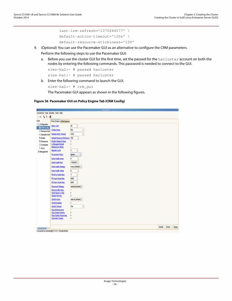
Avago Technologies- 54 -
Syncro CS 9361-8i and Syncro CS 9380-8e Solution User GuideOctober 2014
Chapter 2: Creating the Cluster Creating the Cluster in SuSE Linux Enterprise Server (SLES)
last-lrm-refresh="1370644577" \
default-action-timeout="120s" \
default-resource-stickiness="100"
9. (Optional) You can use the Pacemaker GUI as an alternative to configure the CRM parameters.
Perform the following steps to use the Pacemaker GUI:
a. Before you use the cluster GUI for the first time, set the passwd for the hacluster account on both the nodes by entering the following commands. This password is needed to connect to the GUI.
sles-ha2:~ # passwd hacluster
sles-ha1:~ # passwd hacluster
b. Enter the following command to launch the GUI.
sles-ha2:~ # crm_gui
The Pacemaker GUI appears as shown in the following figures.
Figure 36 Pacemaker GUI on Policy Engine Tab (CRM Config)
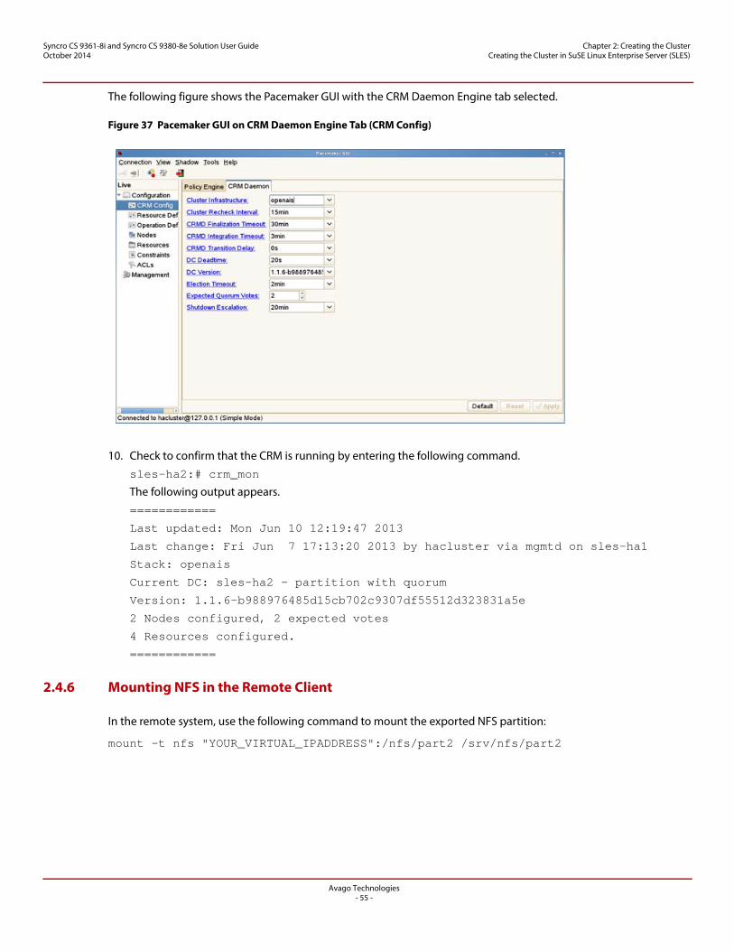
Avago Technologies- 55 -
Syncro CS 9361-8i and Syncro CS 9380-8e Solution User GuideOctober 2014
Chapter 2: Creating the Cluster Creating the Cluster in SuSE Linux Enterprise Server (SLES)
The following figure shows the Pacemaker GUI with the CRM Daemon Engine tab selected.
Figure 37 Pacemaker GUI on CRM Daemon Engine Tab (CRM Config)
10. Check to confirm that the CRM is running by entering the following command.
sles-ha2:# crm_mon
The following output appears.
============
Last updated: Mon Jun 10 12:19:47 2013
Last change: Fri Jun 7 17:13:20 2013 by hacluster via mgmtd on sles-ha1
Stack: openais
Current DC: sles-ha2 - partition with quorum
Version: 1.1.6-b988976485d15cb702c9307df55512d323831a5e
2 Nodes configured, 2 expected votes
4 Resources configured.
============
2.4.6 Mounting NFS in the Remote Client
In the remote system, use the following command to mount the exported NFS partition:
mount -t nfs "YOUR_VIRTUAL_IPADDRESS":/nfs/part2 /srv/nfs/part2
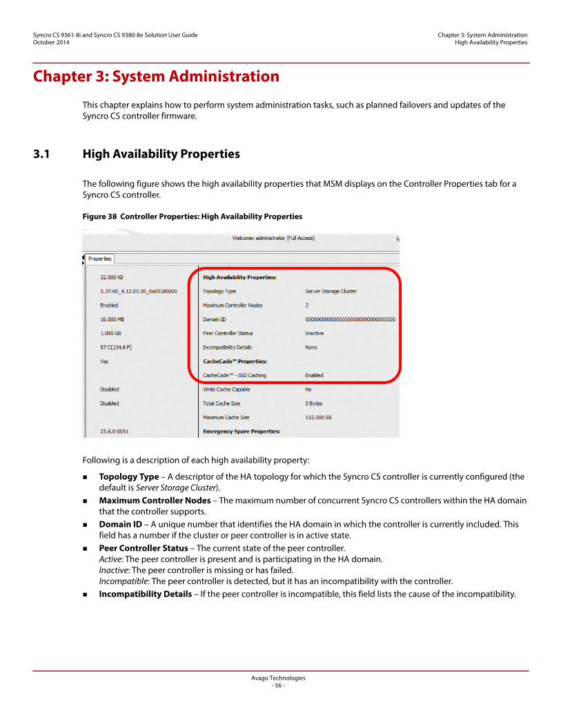
Avago Technologies- 56 -
Syncro CS 9361-8i and Syncro CS 9380-8e Solution User GuideOctober 2014
Chapter 3: System Administration High Availability Properties
Chapter 3: System Administration
This chapter explains how to perform system administration tasks, such as planned failovers and updates of the Syncro CS controller firmware.
3.1 High Availability Properties
The following figure shows the high availability properties that MSM displays on the Controller Properties tab for a Syncro CS controller.
Figure 38 Controller Properties: High Availability Properties
Following is a description of each high availability property:
Topology Type – A descriptor of the HA topology for which the Syncro CS controller is currently configured (the default is Server Storage Cluster).
Maximum Controller Nodes – The maximum number of concurrent Syncro CS controllers within the HA domain that the controller supports.
Domain ID – A unique number that identifies the HA domain in which the controller is currently included. This field has a number if the cluster or peer controller is in active state.
Peer Controller Status – The current state of the peer controller.Active: The peer controller is present and is participating in the HA domain. Inactive: The peer controller is missing or has failed. Incompatible: The peer controller is detected, but it has an incompatibility with the controller.
Incompatibility Details – If the peer controller is incompatible, this field lists the cause of the incompatibility.
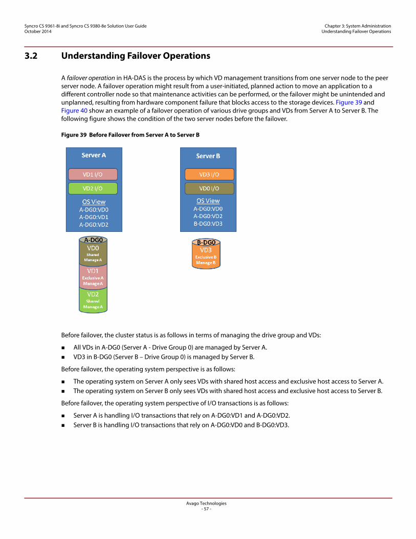
Avago Technologies- 57 -
Syncro CS 9361-8i and Syncro CS 9380-8e Solution User GuideOctober 2014
Chapter 3: System Administration Understanding Failover Operations
3.2 Understanding Failover Operations
A failover operation in HA-DAS is the process by which VD management transitions from one server node to the peer server node. A failover operation might result from a user-initiated, planned action to move an application to a different controller node so that maintenance activities can be performed, or the failover might be unintended and unplanned, resulting from hardware component failure that blocks access to the storage devices. Figure 39 and Figure 40 show an example of a failover operation of various drive groups and VDs from Server A to Server B. The following figure shows the condition of the two server nodes before the failover.
Figure 39 Before Failover from Server A to Server B
Before failover, the cluster status is as follows in terms of managing the drive group and VDs:
All VDs in A-DG0 (Server A - Drive Group 0) are managed by Server A. VD3 in B-DG0 (Server B – Drive Group 0) is managed by Server B.
Before failover, the operating system perspective is as follows:
The operating system on Server A only sees VDs with shared host access and exclusive host access to Server A. The operating system on Server B only sees VDs with shared host access and exclusive host access to Server B.
Before failover, the operating system perspective of I/O transactions is as follows:
Server A is handling I/O transactions that rely on A-DG0:VD1 and A-DG0:VD2. Server B is handling I/O transactions that rely on A-DG0:VD0 and B-DG0:VD3.
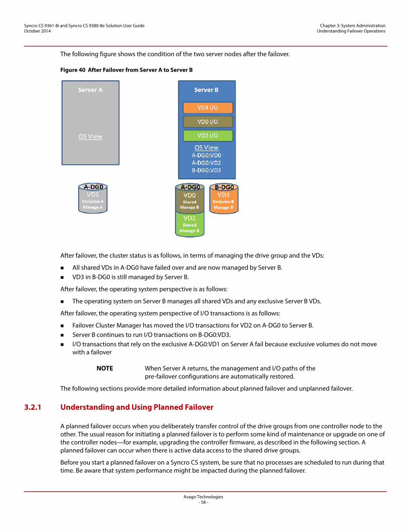
Avago Technologies- 58 -
Syncro CS 9361-8i and Syncro CS 9380-8e Solution User GuideOctober 2014
Chapter 3: System Administration Understanding Failover Operations
The following figure shows the condition of the two server nodes after the failover.
Figure 40 After Failover from Server A to Server B
After failover, the cluster status is as follows, in terms of managing the drive group and the VDs:
All shared VDs in A-DG0 have failed over and are now managed by Server B. VD3 in B-DG0 is still managed by Server B.
After failover, the operating system perspective is as follows:
The operating system on Server B manages all shared VDs and any exclusive Server B VDs.
After failover, the operating system perspective of I/O transactions is as follows:
Failover Cluster Manager has moved the I/O transactions for VD2 on A-DG0 to Server B. Server B continues to run I/O transactions on B-DG0:VD3. I/O transactions that rely on the exclusive A-DG0:VD1 on Server A fail because exclusive volumes do not move
with a failover
NOTE When Server A returns, the management and I/O paths of the pre-failover configurations are automatically restored.
The following sections provide more detailed information about planned failover and unplanned failover.
3.2.1 Understanding and Using Planned Failover
A planned failover occurs when you deliberately transfer control of the drive groups from one controller node to the other. The usual reason for initiating a planned failover is to perform some kind of maintenance or upgrade on one of the controller nodes—for example, upgrading the controller firmware, as described in the following section. A planned failover can occur when there is active data access to the shared drive groups.
Before you start a planned failover on a Syncro CS system, be sure that no processes are scheduled to run during that time. Be aware that system performance might be impacted during the planned failover.
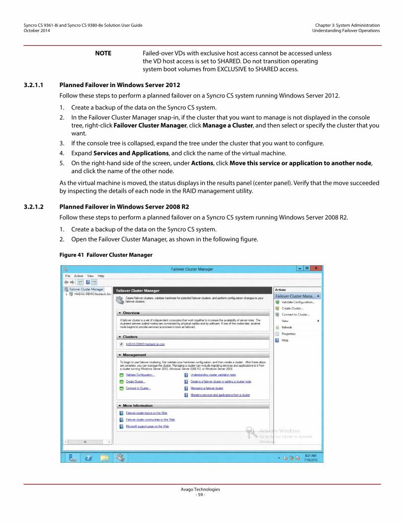
Avago Technologies- 59 -
Syncro CS 9361-8i and Syncro CS 9380-8e Solution User GuideOctober 2014
Chapter 3: System Administration Understanding Failover Operations
NOTE Failed-over VDs with exclusive host access cannot be accessed unless the VD host access is set to SHARED. Do not transition operating system boot volumes from EXCLUSIVE to SHARED access.
3.2.1.1 Planned Failover in Windows Server 2012
Follow these steps to perform a planned failover on a Syncro CS system running Windows Server 2012.
1. Create a backup of the data on the Syncro CS system.
2. In the Failover Cluster Manager snap-in, if the cluster that you want to manage is not displayed in the console tree, right-click Failover Cluster Manager, click Manage a Cluster, and then select or specify the cluster that you want.
3. If the console tree is collapsed, expand the tree under the cluster that you want to configure.
4. Expand Services and Applications, and click the name of the virtual machine.
5. On the right-hand side of the screen, under Actions, click Move this service or application to another node, and click the name of the other node.
As the virtual machine is moved, the status displays in the results panel (center panel). Verify that the move succeeded by inspecting the details of each node in the RAID management utility.
3.2.1.2 Planned Failover in Windows Server 2008 R2
Follow these steps to perform a planned failover on a Syncro CS system running Windows Server 2008 R2.
1. Create a backup of the data on the Syncro CS system.
2. Open the Failover Cluster Manager, as shown in the following figure.
Figure 41 Failover Cluster Manager
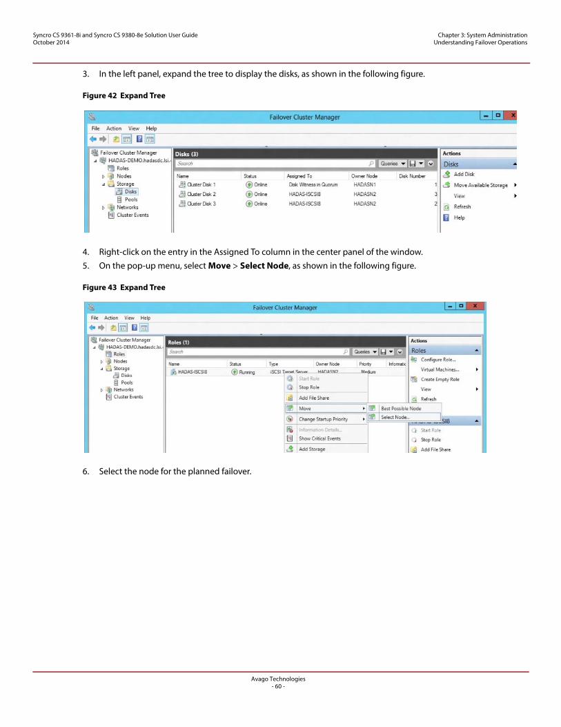
Avago Technologies- 60 -
Syncro CS 9361-8i and Syncro CS 9380-8e Solution User GuideOctober 2014
Chapter 3: System Administration Understanding Failover Operations
3. In the left panel, expand the tree to display the disks, as shown in the following figure.
Figure 42 Expand Tree
4. Right-click on the entry in the Assigned To column in the center panel of the window.
5. On the pop-up menu, select Move > Select Node, as shown in the following figure.
Figure 43 Expand Tree
6. Select the node for the planned failover.
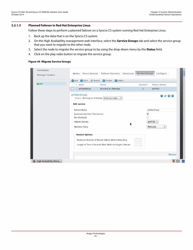
Avago Technologies- 61 -
Syncro CS 9361-8i and Syncro CS 9380-8e Solution User GuideOctober 2014
Chapter 3: System Administration Understanding Failover Operations
3.2.1.3 Planned Failover in Red Hat Enterprise Linux
Follow these steps to perform a planned failover on a Syncro CS system running Red Hat Enterprise Linux.
1. Back up the data that is on the Syncro CS system.
2. On the High Availability management web interface, select the Service Groups tab and select the service group that you want to migrate to the other node.
3. Select the node to migrate the service group to by using the drop-down menu by the Status field.
4. Click on the play radio button to migrate the service group.
Figure 44 Migrate Service Groups
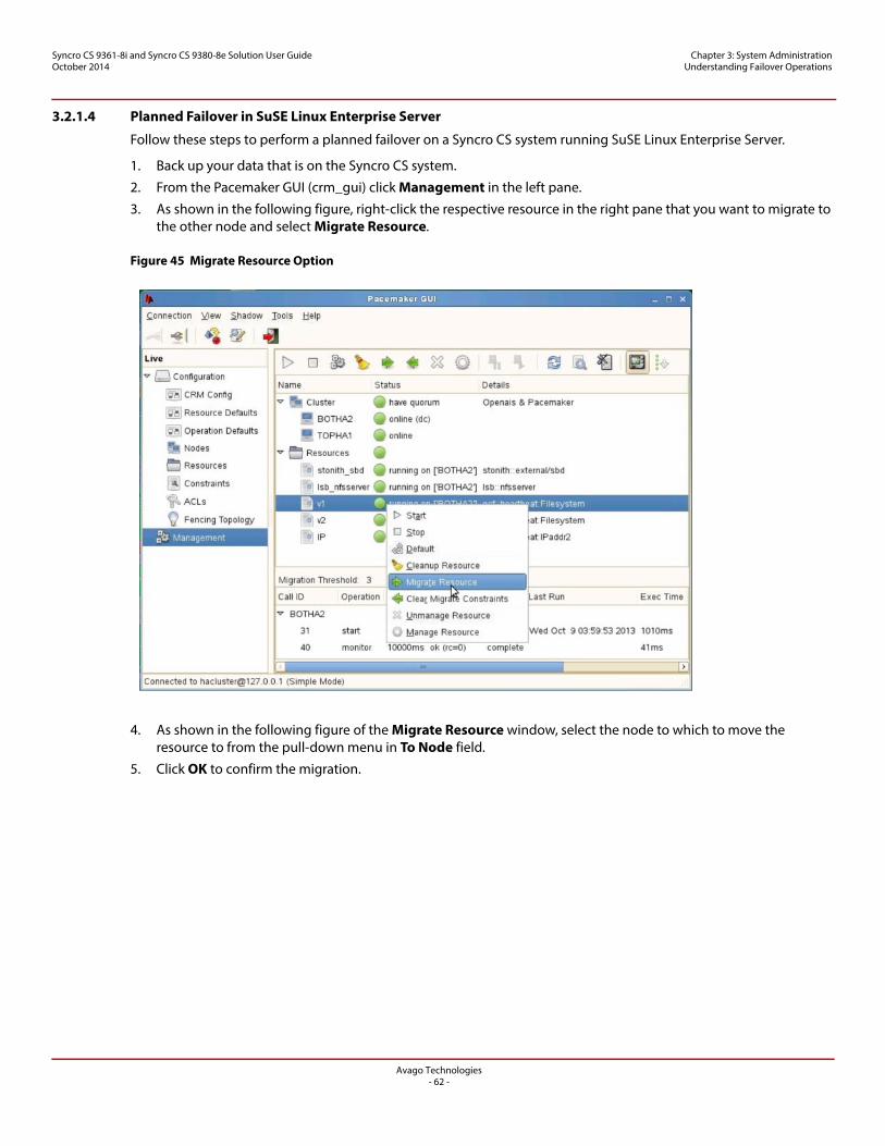
Avago Technologies- 62 -
Syncro CS 9361-8i and Syncro CS 9380-8e Solution User GuideOctober 2014
Chapter 3: System Administration Understanding Failover Operations
3.2.1.4 Planned Failover in SuSE Linux Enterprise Server
Follow these steps to perform a planned failover on a Syncro CS system running SuSE Linux Enterprise Server.
1. Back up your data that is on the Syncro CS system.
2. From the Pacemaker GUI (crm_gui) click Management in the left pane.
3. As shown in the following figure, right-click the respective resource in the right pane that you want to migrate to the other node and select Migrate Resource.
Figure 45 Migrate Resource Option
4. As shown in the following figure of the Migrate Resource window, select the node to which to move the resource to from the pull-down menu in To Node field.
5. Click OK to confirm the migration.
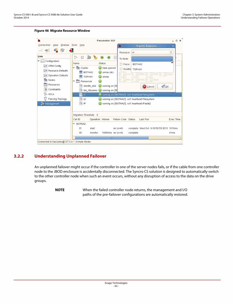
Avago Technologies- 63 -
Syncro CS 9361-8i and Syncro CS 9380-8e Solution User GuideOctober 2014
Chapter 3: System Administration Understanding Failover Operations
Figure 46 Migrate Resource Window
3.2.2 Understanding Unplanned Failover
An unplanned failover might occur if the controller in one of the server nodes fails, or if the cable from one controller node to the JBOD enclosure is accidentally disconnected. The Syncro CS solution is designed to automatically switch to the other controller node when such an event occurs, without any disruption of access to the data on the drive groups.
NOTE When the failed controller node returns, the management and I/O paths of the pre-failover configurations are automatically restored.
Avago Technologies- 64 -
Syncro CS 9361-8i and Syncro CS 9380-8e Solution User GuideOctober 2014
Chapter 3: System Administration Updating the Syncro CS Controller Firmware
3.3 Updating the Syncro CS Controller Firmware
Follow these steps to update the firmware on the Syncro CS controller board. You must perform the update only on the controller node that is not currently accessing the drive groups.
NOTE Be sure that the version of firmware selected for the update is specified for Syncro CS controllers. If you updating to a version of controller firmware that does not support Syncro CS controllers, you will experience a loss of HA-DAS functionality.
1. If necessary, perform a planned failover as described in the previous section to transfer control of the drive groups to the other controller node.
2. Start the MSM utility on the controller node that does not currently own the cluster.
NOTE To determine which node currently owns the cluster in Windows Server 2012, follow the steps in Section 3.2.1.2, Planned Failover in Windows Server 2008 R2, up to step 3, where information about the cluster disks is displayed in the center panel. The current owner of the cluster is listed in the Owner Node column.
3. In the left panel of the MSM window, click the icon of the controller that requires an upgrade.
4. In the MSM window, select Go To > Controller > Update Controller Firmware.
5. Click Browse to locate the .rom update file.
You cannot perform controller firmware update until the firmware update process on this node is complete.
6. After you locate the file, click Ok.
The MSM software displays the version of the existing firmware and the version of the new firmware file.
7. When you are prompted to indicate whether you want to upgrade the firmware, click Yes.
A pop-up window appears that asks whether you want to perform an Online Firmware Update (OFU, also referred to as ResetNow).
NOTE In Syncro CS, if you allow IOs during a firmware update (that has a cache layout change), then when the new firmware takes over after reboot, the controller cannot recover the cache that still needs to be written to the drives (dirty cache). The new local IOs (even though they are in write-through mode) and the mirror IOs are marked as dirty cache after the new firmware takes over.To have the controller recover any dirty cache, select the OFU option when you update the firmware.
8. Click Yes or No in the pop-up window.
The controller is updated with the new firmware code contained in the .rom file.
NOTE If you select OFU, the controller reboots after the new firmware is flashed, and you do not need to reboot the system.
9. If you did not select OFU in step 7, reboot the controller node after the new firmware is flashed.
The new firmware does not take effect until reboot.
10. If desired, use planned failover to transfer control of the drive groups back to the controller node you just upgraded.
11. Repeat this process for the other controller.
12. Restore the cluster to its non-failed-over mode.
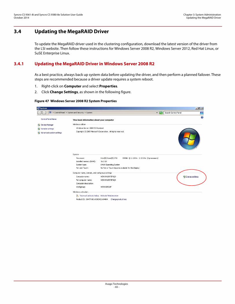
Avago Technologies- 65 -
Syncro CS 9361-8i and Syncro CS 9380-8e Solution User GuideOctober 2014
Chapter 3: System Administration Updating the MegaRAID Driver
3.4 Updating the MegaRAID Driver
To update the MegaRAID driver used in the clustering configuration, download the latest version of the driver from the LSI website. Then follow these instructions for Windows Server 2008 R2, Windows Server 2012, Red Hat Linux, or SuSE Enterprise Linux.
3.4.1 Updating the MegaRAID Driver in Windows Server 2008 R2
As a best practice, always back up system data before updating the driver, and then perform a planned failover. These steps are recommended because a driver update requires a system reboot.
1. Right-click on Computer and select Properties.
2. Click Change Settings, as shown in the following figure.
Figure 47 Windows Server 2008 R2 System Properties
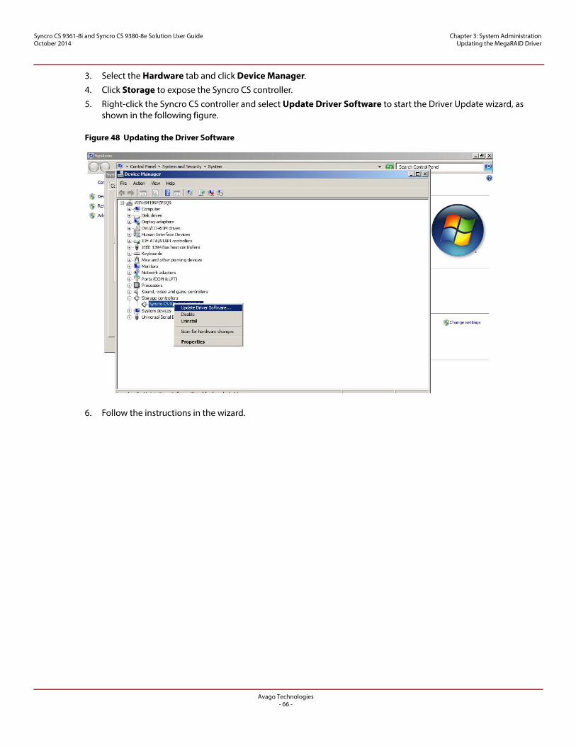
Avago Technologies- 66 -
Syncro CS 9361-8i and Syncro CS 9380-8e Solution User GuideOctober 2014
Chapter 3: System Administration Updating the MegaRAID Driver
3. Select the Hardware tab and click Device Manager.
4. Click Storage to expose the Syncro CS controller.
5. Right-click the Syncro CS controller and select Update Driver Software to start the Driver Update wizard, as shown in the following figure.
Figure 48 Updating the Driver Software
6. Follow the instructions in the wizard.
Syncro CS 92
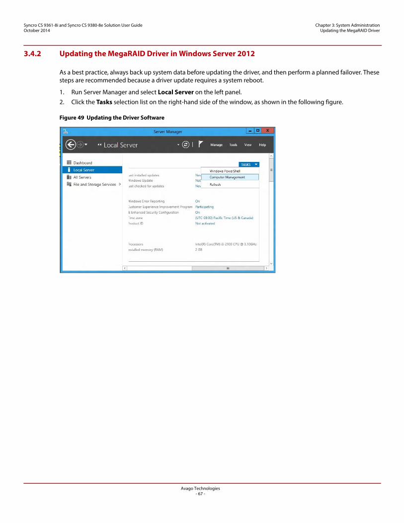
Avago Technologies- 67 -
Syncro CS 9361-8i and Syncro CS 9380-8e Solution User GuideOctober 2014
Chapter 3: System Administration Updating the MegaRAID Driver
3.4.2 Updating the MegaRAID Driver in Windows Server 2012
As a best practice, always back up system data before updating the driver, and then perform a planned failover. These steps are recommended because a driver update requires a system reboot.
1. Run Server Manager and select Local Server on the left panel.
2. Click the Tasks selection list on the right-hand side of the window, as shown in the following figure.
Figure 49 Updating the Driver Software

Avago Technologies- 68 -
Syncro CS 9361-8i and Syncro CS 9380-8e Solution User GuideOctober 2014
Chapter 3: System Administration Updating the MegaRAID Driver
3. Select Computer Management, then click Device Manager.
4. Click Storage controllers to display the Syncro CS controller.
5. Right-click on the Syncro CS controller and select Update Driver Software, as shown in the following figure, to start the Driver Update wizard.
Figure 50 Updating the Driver Software
6. Follow the instructions in the wizard.
3.4.3 Updating the Red Hat Linux System Driver
Perform the following steps to install or update to the latest version of the MegaSAS driver:
1. Boot the system.
2. Go to Console (your terminal GUI).
3. Install the Dynamic Kernel Module Support (DKMS) driver RPM.
Uninstall the earlier version first, if needed.
4. Install the MegaSAS driver RPM.
Uninstall the earlier version first, if needed.
5. Reboot the system to load the driver.
3.4.4 Updating the SuSE Linux Enterprise Server 11 Driver
Perform the following steps to install or upgrade to the latest version of the MegaSAS driver:
1. Boot the system.
2. Go to Console (your terminal GUI).
3. Run Dynamic Kernel Module Support (DKMS) driver RPM.
Uninstall the earlier version first, if needed.
Syncro CS 92
Avago Technologies- 69 -
Syncro CS 9361-8i and Syncro CS 9380-8e Solution User GuideOctober 2014
Chapter 3: System Administration Performing Preventive Measures on Disk Drives and VDs
4. Install the MegaSAS driver RPM.
Uninstall the earlier version first, if necessary.
5. Reboot the system to load the driver.
3.5 Performing Preventive Measures on Disk Drives and VDs
The following drive and VD-level operations help to proactively detect disk drive and VD errors that could potentially cause the failure of a controller node. For more information about these operations, refer to the MegaRAID SAS Software User Guide.
Patrol Read – A patrol read periodically verifies all sectors of disk drives that are connected to a controller, including the system reserved area in the RAID configured drives. You can run a patrol read for all RAID levels and for all hot spare drives. A patrol read is initiated only when the controller is idle for a defined time period and has no other background activities.
Consistency Check – You should periodically run a consistency check on fault-tolerant VDs (RAID 1, RAID 5, RAID 6, RAID 10, RAID 50, and RAID 60 configurations; RAID 0 does not provide data redundancy). A consistency check scans the VDs to determine whether the data has become corrupted and needs to be restored.
For example, in a VD with parity, a consistency check computes the data on one drive and compares the results to the contents of the parity drive. You must run a consistency check if you suspect that the data on the VD might be corrupted.
NOTE Be sure to back up the data before running a consistency check if you think the data might be corrupted.

Avago Technologies- 70 -
Syncro CS 9361-8i and Syncro CS 9380-8e Solution User GuideOctober 2014
Chapter 4: Troubleshooting Verifying HA-DAS Support in Tools and the OS Driver
Chapter 4: Troubleshooting
This chapter has information about troubleshooting a Syncro CS system.
4.1 Verifying HA-DAS Support in Tools and the OS Driver
Not all versions of MegaRAID Storage Manager (MSM) support HA-DAS. The MSM versions that include support for HA-DAS have specific references to clustering. It is not always possible to determine the level of support from the MSM version number. Instead, look for the MSM user interface features that indicate clustering support. If the second item in the MSM Properties box on the dashboard for the HA-DAS controller is High Availability Cluster status, the version supports HA-DAS. This entry does not appear on versions of MSM without HA-DAS support.
You can also verify HA-DAS support in the MSM Create Virtual Drive wizard. A Provide Shared Access check box appears only if the MSM version supports clustering, as shown in the following figure.
Figure 51 Provide Shared Access Property
Versions of MSM that support HA-DAS also require an HA-DAS-capable OS driver to present HA-DAS features. The in-box driver for Windows Server 2012, RHEL 6.4, and SLES 11 SP3 do not present HA-DAS features in MSM.
To determine if your version of StorCLI supports HA-DAS, enter this help command:
Storcli /c0 add vd ?
If the help text that is returned includes information about the Host Access Policy: Exclusive to peer Controller / Exclusive / Shared parameter, your version of StorCLI supports HA-DAS.
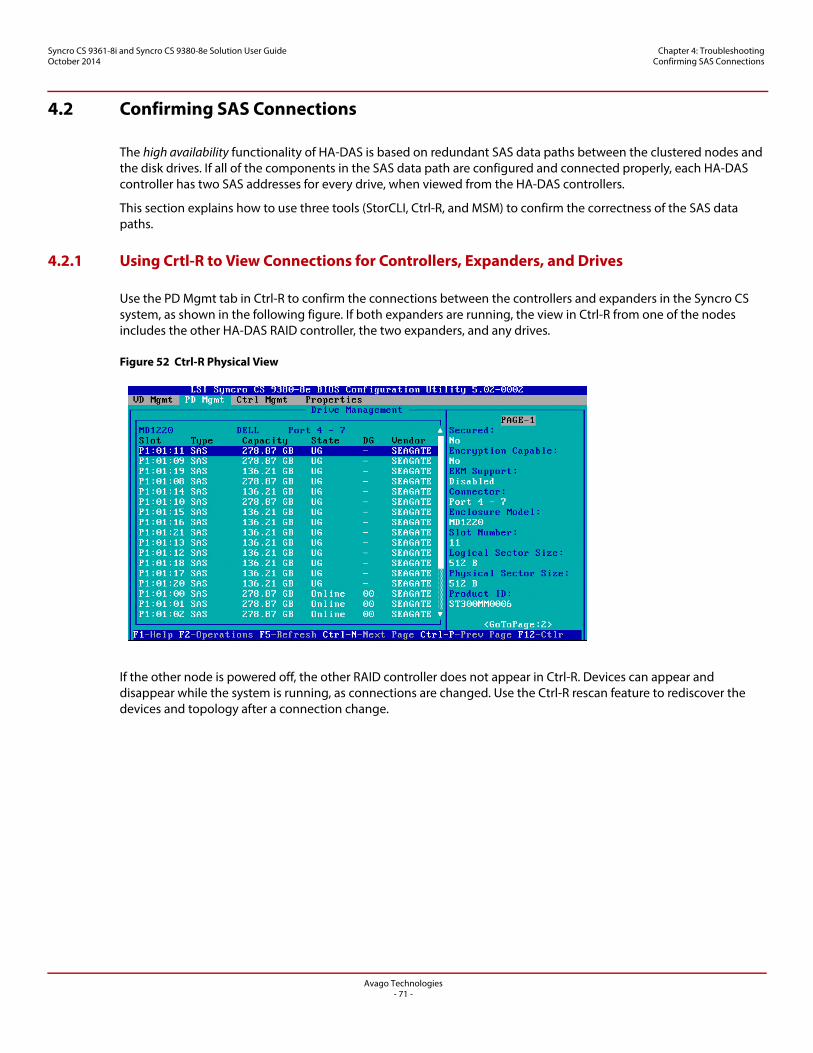
Avago Technologies- 71 -
Syncro CS 9361-8i and Syncro CS 9380-8e Solution User GuideOctober 2014
Chapter 4: Troubleshooting Confirming SAS Connections
4.2 Confirming SAS Connections
The high availability functionality of HA-DAS is based on redundant SAS data paths between the clustered nodes and the disk drives. If all of the components in the SAS data path are configured and connected properly, each HA-DAS controller has two SAS addresses for every drive, when viewed from the HA-DAS controllers.
This section explains how to use three tools (StorCLI, Ctrl-R, and MSM) to confirm the correctness of the SAS data paths.
4.2.1 Using Crtl-R to View Connections for Controllers, Expanders, and Drives
Use the PD Mgmt tab in Ctrl-R to confirm the connections between the controllers and expanders in the Syncro CS system, as shown in the following figure. If both expanders are running, the view in Ctrl-R from one of the nodes includes the other HA-DAS RAID controller, the two expanders, and any drives.
Figure 52 Ctrl-R Physical View
If the other node is powered off, the other RAID controller does not appear in Ctrl-R. Devices can appear and disappear while the system is running, as connections are changed. Use the Ctrl-R rescan feature to rediscover the devices and topology after a connection change.
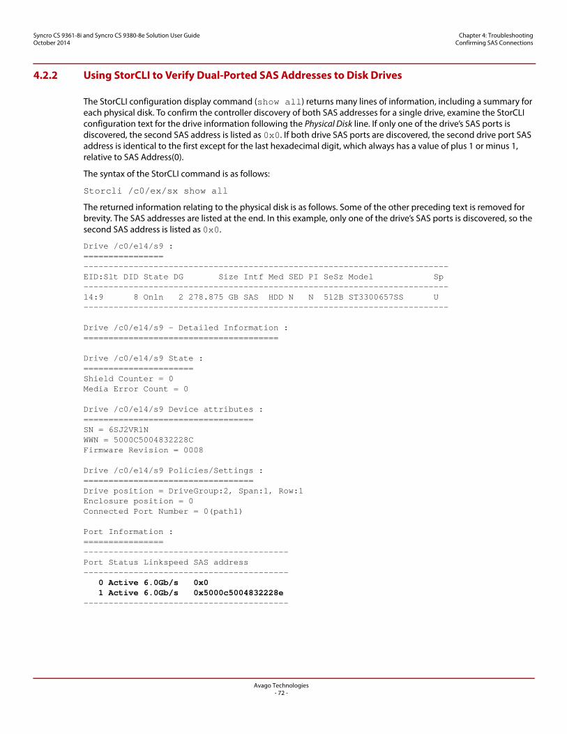
Avago Technologies- 72 -
Syncro CS 9361-8i and Syncro CS 9380-8e Solution User GuideOctober 2014
Chapter 4: Troubleshooting Confirming SAS Connections
4.2.2 Using StorCLI to Verify Dual-Ported SAS Addresses to Disk Drives
The StorCLI configuration display command (show all) returns many lines of information, including a summary for each physical disk. To confirm the controller discovery of both SAS addresses for a single drive, examine the StorCLI configuration text for the drive information following the Physical Disk line. If only one of the drive’s SAS ports is discovered, the second SAS address is listed as 0x0. If both drive SAS ports are discovered, the second drive port SAS address is identical to the first except for the last hexadecimal digit, which always has a value of plus 1 or minus 1, relative to SAS Address(0).
The syntax of the StorCLI command is as follows:
Storcli /c0/ex/sx show all
The returned information relating to the physical disk is as follows. Some of the other preceding text is removed for brevity. The SAS addresses are listed at the end. In this example, only one of the drive’s SAS ports is discovered, so the second SAS address is listed as 0x0.
Drive /c0/e14/s9 :================-------------------------------------------------------------------------EID:Slt DID State DG Size Intf Med SED PI SeSz Model Sp-------------------------------------------------------------------------14:9 8 Onln 2 278.875 GB SAS HDD N N 512B ST3300657SS U-------------------------------------------------------------------------
Drive /c0/e14/s9 - Detailed Information :=======================================
Drive /c0/e14/s9 State :======================Shield Counter = 0Media Error Count = 0
Drive /c0/e14/s9 Device attributes :==================================SN = 6SJ2VR1NWWN = 5000C5004832228CFirmware Revision = 0008
Drive /c0/e14/s9 Policies/Settings :==================================Drive position = DriveGroup:2, Span:1, Row:1Enclosure position = 0Connected Port Number = 0(path1)
Port Information :================-----------------------------------------Port Status Linkspeed SAS address----------------------------------------- 0 Active 6.0Gb/s 0x0 1 Active 6.0Gb/s 0x5000c5004832228e-----------------------------------------
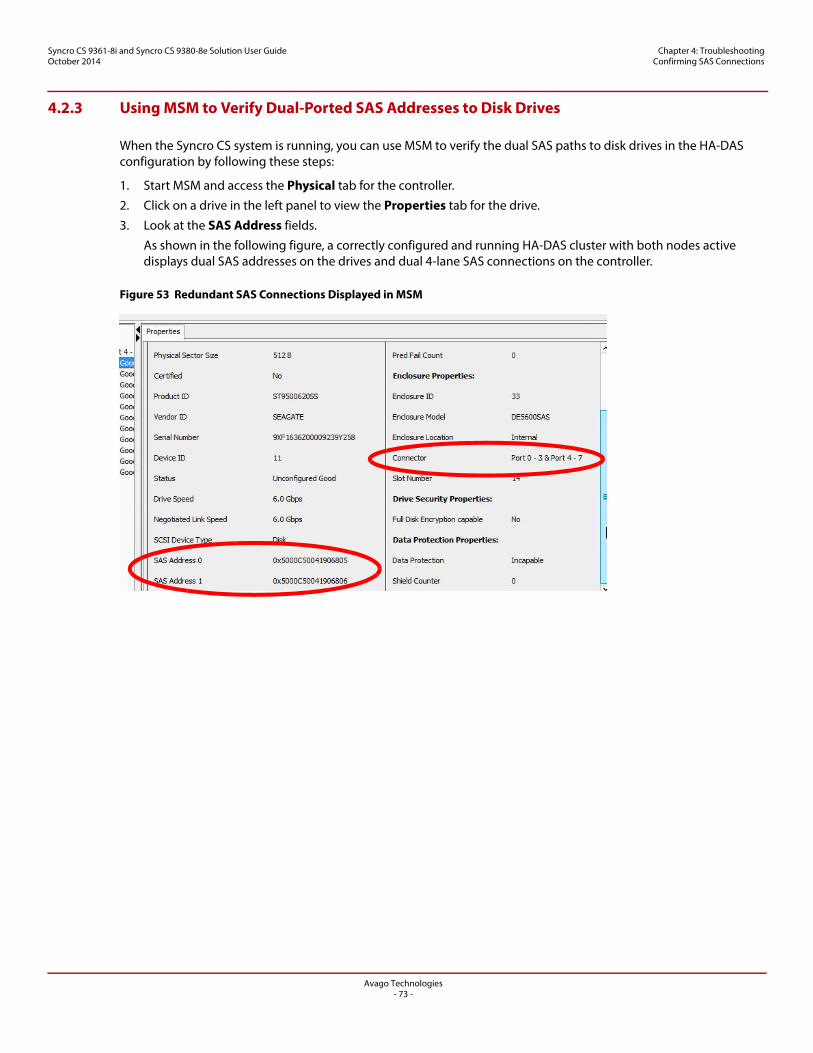
Avago Technologies- 73 -
Syncro CS 9361-8i and Syncro CS 9380-8e Solution User GuideOctober 2014
Chapter 4: Troubleshooting Confirming SAS Connections
4.2.3 Using MSM to Verify Dual-Ported SAS Addresses to Disk Drives
When the Syncro CS system is running, you can use MSM to verify the dual SAS paths to disk drives in the HA-DAS configuration by following these steps:
1. Start MSM and access the Physical tab for the controller.
2. Click on a drive in the left panel to view the Properties tab for the drive.
3. Look at the SAS Address fields.
As shown in the following figure, a correctly configured and running HA-DAS cluster with both nodes active displays dual SAS addresses on the drives and dual 4-lane SAS connections on the controller.
Figure 53 Redundant SAS Connections Displayed in MSM
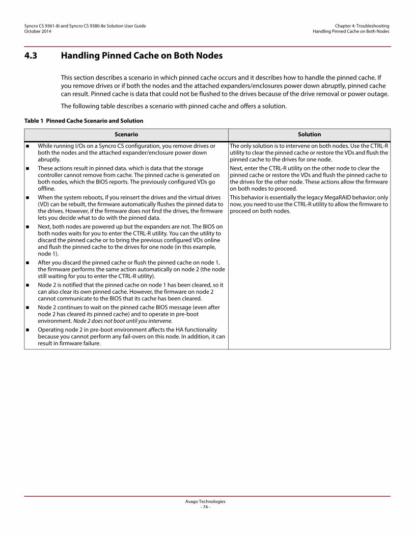
Avago Technologies- 74 -
Syncro CS 9361-8i and Syncro CS 9380-8e Solution User GuideOctober 2014
Chapter 4: Troubleshooting Handling Pinned Cache on Both Nodes
4.3 Handling Pinned Cache on Both Nodes
This section describes a scenario in which pinned cache occurs and it describes how to handle the pinned cache. If you remove drives or if both the nodes and the attached expanders/enclosures power down abruptly, pinned cache can result. Pinned cache is data that could not be flushed to the drives because of the drive removal or power outage.
The following table describes a scenario with pinned cache and offers a solution.
Table 1 Pinned Cache Scenario and Solution
Scenario Solution
While running I/Os on a Syncro CS configuration, you remove drives or both the nodes and the attached expander/enclosure power down abruptly.
These actions result in pinned data. which is data that the storage controller cannot remove from cache. The pinned cache is generated on both nodes, which the BIOS reports. The previously configured VDs go offline.
When the system reboots, if you reinsert the drives and the virtual drives (VD) can be rebuilt, the firmware automatically flushes the pinned data to the drives. However, if the firmware does not find the drives, the firmware lets you decide what to do with the pinned data.
Next, both nodes are powered up but the expanders are not. The BIOS on both nodes waits for you to enter the CTRL-R utility. You can the utility to discard the pinned cache or to bring the previous configured VDs online and flush the pinned cache to the drives for one node (in this example, node 1).
After you discard the pinned cache or flush the pinned cache on node 1, the firmware performs the same action automatically on node 2 (the node still waiting for you to enter the CTRL-R utility).
Node 2 is notified that the pinned cache on node 1 has been cleared, so it can also clear its own pinned cache. However, the firmware on node 2 cannot communicate to the BIOS that its cache has been cleared.
Node 2 continues to wait on the pinned cache BIOS message (even after node 2 has cleared its pinned cache) and to operate in pre-boot environment. Node 2 does not boot until you intervene.
Operating node 2 in pre-boot environment affects the HA functionality because you cannot perform any fail-overs on this node. In addition, it can result in firmware failure.
The only solution is to intervene on both nodes. Use the CTRL-R utility to clear the pinned cache or restore the VDs and flush the pinned cache to the drives for one node. Next, enter the CTRL-R utility on the other node to clear the pinned cache or restore the VDs and flush the pinned cache to the drives for the other node. These actions allow the firmware on both nodes to proceed. This behavior is essentially the legacy MegaRAID behavior; only now, you need to use the CTRL-R utility to allow the firmware to proceed on both nodes.
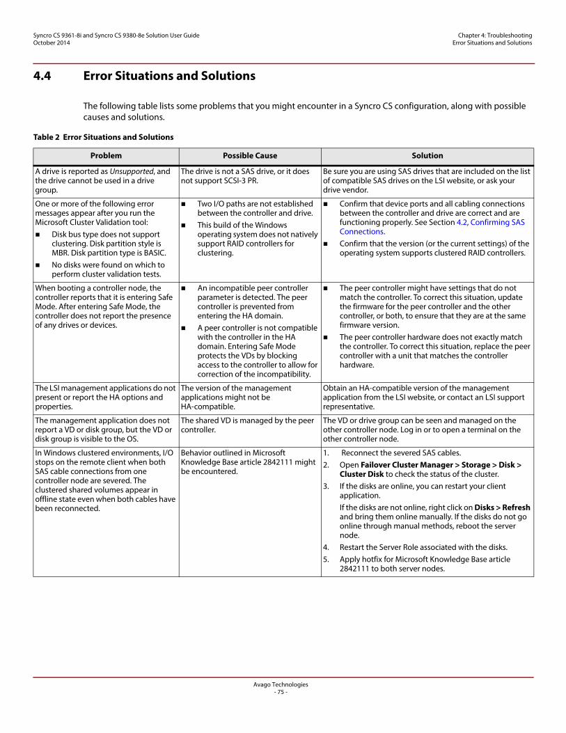
Avago Technologies- 75 -
Syncro CS 9361-8i and Syncro CS 9380-8e Solution User GuideOctober 2014
Chapter 4: Troubleshooting Error Situations and Solutions
4.4 Error Situations and Solutions
The following table lists some problems that you might encounter in a Syncro CS configuration, along with possible causes and solutions.
Table 2 Error Situations and Solutions
Problem Possible Cause Solution
A drive is reported as Unsupported, and the drive cannot be used in a drive group.
The drive is not a SAS drive, or it does not support SCSI-3 PR.
Be sure you are using SAS drives that are included on the list of compatible SAS drives on the LSI website, or ask your drive vendor.
One or more of the following error messages appear after you run the Microsoft Cluster Validation tool: Disk bus type does not support
clustering. Disk partition style is MBR. Disk partition type is BASIC.
No disks were found on which to perform cluster validation tests.
Two I/O paths are not established between the controller and drive.
This build of the Windows operating system does not natively support RAID controllers for clustering.
Confirm that device ports and all cabling connections between the controller and drive are correct and are functioning properly. See Section 4.2, Confirming SAS Connections.
Confirm that the version (or the current settings) of the operating system supports clustered RAID controllers.
When booting a controller node, the controller reports that it is entering Safe Mode. After entering Safe Mode, the controller does not report the presence of any drives or devices.
An incompatible peer controller parameter is detected. The peer controller is prevented from entering the HA domain.
A peer controller is not compatible with the controller in the HA domain. Entering Safe Mode protects the VDs by blocking access to the controller to allow for correction of the incompatibility.
The peer controller might have settings that do not match the controller. To correct this situation, update the firmware for the peer controller and the other controller, or both, to ensure that they are at the same firmware version.
The peer controller hardware does not exactly match the controller. To correct this situation, replace the peer controller with a unit that matches the controller hardware.
The LSI management applications do not present or report the HA options and properties.
The version of the management applications might not be HA-compatible.
Obtain an HA-compatible version of the management application from the LSI website, or contact an LSI support representative.
The management application does not report a VD or disk group, but the VD or disk group is visible to the OS.
The shared VD is managed by the peer controller.
The VD or drive group can be seen and managed on the other controller node. Log in or to open a terminal on the other controller node.
In Windows clustered environments, I/O stops on the remote client when both SAS cable connections from one controller node are severed. The clustered shared volumes appear in offline state even when both cables have been reconnected.
Behavior outlined in Microsoft Knowledge Base article 2842111 might be encountered.
1. Reconnect the severed SAS cables.2. Open Failover Cluster Manager > Storage > Disk >
Cluster Disk to check the status of the cluster.3. If the disks are online, you can restart your client
application.If the disks are not online, right click on Disks > Refresh and bring them online manually. If the disks do not go online through manual methods, reboot the server node.
4. Restart the Server Role associated with the disks.5. Apply hotfix for Microsoft Knowledge Base article
2842111 to both server nodes.
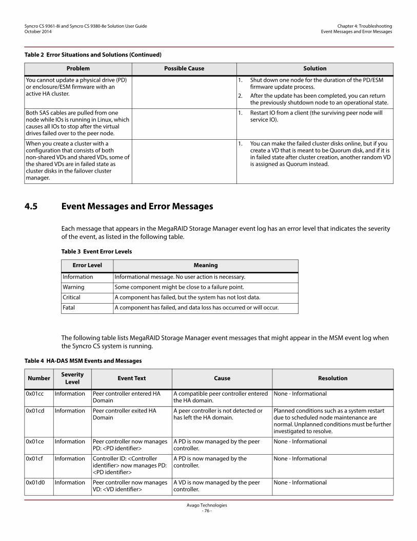
Avago Technologies- 76 -
Syncro CS 9361-8i and Syncro CS 9380-8e Solution User GuideOctober 2014
Chapter 4: Troubleshooting Event Messages and Error Messages
4.5 Event Messages and Error Messages
Each message that appears in the MegaRAID Storage Manager event log has an error level that indicates the severity of the event, as listed in the following table.
Error Level Meaning
The following table lists MegaRAID Storage Manager event messages that might appear in the MSM event log when the Syncro CS system is running.
You cannot update a physical drive (PD) or enclosure/ESM firmware with an active HA cluster.
1. Shut down one node for the duration of the PD/ESM firmware update process.
2. After the update has been completed, you can return the previously shutdown node to an operational state.
Both SAS cables are pulled from one node while IOs is running in Linux, which causes all IOs to stop after the virtual drives failed over to the peer node.
1. Restart IO from a client (the surviving peer node will service IO).
When you create a cluster with a configuration that consists of both non-shared VDs and shared VDs, some of the shared VDs are in failed state as cluster disks in the failover cluster manager.
1. You can make the failed cluster disks online, but if you create a VD that is meant to be Quorum disk, and if it is in failed state after cluster creation, another random VD is assigned as Quorum instead.
Table 3 Event Error Levels
Error Level Meaning
Information Informational message. No user action is necessary.
Warning Some component might be close to a failure point.
Critical A component has failed, but the system has not lost data.
Fatal A component has failed, and data loss has occurred or will occur.
Table 4 HA-DAS MSM Events and Messages
Number Severity Level Event Text Cause Resolution
0x01cc Information Peer controller entered HA Domain
A compatible peer controller entered the HA domain.
None - Informational
0x01cd Information Peer controller exited HA Domain
A peer controller is not detected or has left the HA domain.
Planned conditions such as a system restart due to scheduled node maintenance are normal. Unplanned conditions must be further investigated to resolve.
0x01ce Information Peer controller now manages PD: <PD identifier>
A PD is now managed by the peer controller.
None - Informational
0x01cf Information Controller ID: <Controller identifier> now manages PD: <PD identifier>
A PD is now managed by the controller.
None - Informational
0x01d0 Information Peer controller now manages VD: <VD identifier>
A VD is now managed by the peer controller.
None - Informational
Table 2 Error Situations and Solutions (Continued)
Problem Possible Cause Solution

Avago Technologies- 77 -
Syncro CS 9361-8i and Syncro CS 9380-8e Solution User GuideOctober 2014
Chapter 4: Troubleshooting Event Messages and Error Messages
0x01d1 Information Controller ID: <Controller identifier> now manages VD: <VD identifier>
A VD is now managed by the controller.
None - Informational
0x01d2 Critical Target ID conflict detected. VD: <VD identifier> access is restricted from Peer controller
Multiple VD target IDs are in conflict due to scenarios that might occur when the HA domain has a missing cross-link that establishes direct controller-to-controller communication (called split-brain condition).
The Peer controller cannot access VDs with conflicting IDs. To resolve, re-establish the controller-to-controller communication path to both controllers and perform a reset of one system.
0x01d3 Information Shared access set for VD: <VD identifier>
A VD access policy is set to Shared. None - Informational
0x01d4 Information Exclusive access set for VD: <VD identifier>
A VD access policy is set to Exclusive. None - Informational
0x01d5 Warning VD: <VD identifier> is incompatible in the HA domain
The controller or peer controller does not support the VD type.
Attempts to create a VD that is not supported by the peer controller result in a creation failure. To resolve, create a VD that aligns with the peer controller VD support level. Attempts to introduce an unsupported VD that is managed by the peer controller result in rejection of the VD by the controller. To resolve, convert the unsupported VD to one that is supported by both controllers, or migrate the data to a VD that is supported by both controllers.
0x01d6 Warning Peer controller settings are incompatible
An incompatible peer controller parameter is detected. The peer controller is rejected from entering the HA domain.
The peer controller might have settings that do not match the controller. These settings can be corrected by a firmware update. To resolve, update the firmware for the peer controller and/or controller to ensure that they are at the same version.
0x01d7 Warning Peer Controller hardware is incompatible with HA Domain ID: <Domain identifier>
An incompatible peer controller is detected. The peer controller is rejected from entering the HA domain.
The peer controller hardware does not exactly match the controller. To resolve, replace the peer controller with a unit that matches the controller hardware
0x01d8 Warning Controller property mismatch detected with Peer controller
A mismatch exists between the controller properties and the peer controller properties.
Controller properties do not match between the controller and peer controller. To resolve, set the mismatched controller property to a common value.
0x01d9 Warning FW version does not match Peer controller
A mismatch exists between the controller and peer controller firmware versions.
This condition can occur when an HA controller is introduced to the HA domain during a controller firmware update. To resolve, upgrade or downgrade the controller or peer controller firmware to the same version.
0x01da Warning Advanced Software Option(s) <option names> mismatch detected with Peer controller
A mismatch exists between the controller and peer controller advanced software options.
This case does not result in an incompatibility that can affect HA functionality, but it can impact the effectiveness of the advanced software options. To resolve, enable an identical level of advanced software options on both controllers.
Table 4 HA-DAS MSM Events and Messages (Continued)
Number Severity Level Event Text Cause Resolution
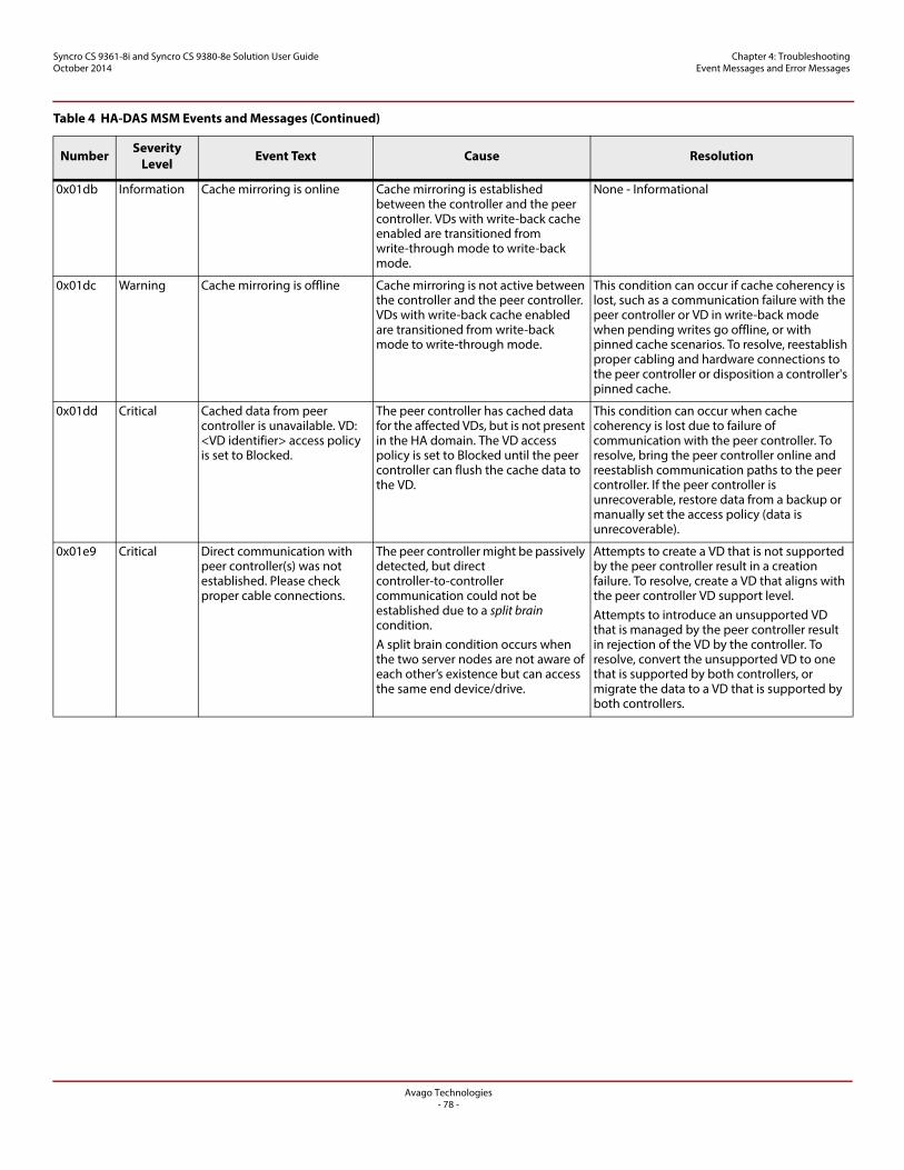
Avago Technologies- 78 -
Syncro CS 9361-8i and Syncro CS 9380-8e Solution User GuideOctober 2014
Chapter 4: Troubleshooting Event Messages and Error Messages
0x01db Information Cache mirroring is online Cache mirroring is established between the controller and the peer controller. VDs with write-back cache enabled are transitioned from write-through mode to write-back mode.
None - Informational
0x01dc Warning Cache mirroring is offline Cache mirroring is not active between the controller and the peer controller. VDs with write-back cache enabled are transitioned from write-back mode to write-through mode.
This condition can occur if cache coherency is lost, such as a communication failure with the peer controller or VD in write-back mode when pending writes go offline, or with pinned cache scenarios. To resolve, reestablish proper cabling and hardware connections to the peer controller or disposition a controller's pinned cache.
0x01dd Critical Cached data from peer controller is unavailable. VD: <VD identifier> access policy is set to Blocked.
The peer controller has cached data for the affected VDs, but is not present in the HA domain. The VD access policy is set to Blocked until the peer controller can flush the cache data to the VD.
This condition can occur when cache coherency is lost due to failure of communication with the peer controller. To resolve, bring the peer controller online and reestablish communication paths to the peer controller. If the peer controller is unrecoverable, restore data from a backup or manually set the access policy (data is unrecoverable).
0x01e9 Critical Direct communication with peer controller(s) was not established. Please check proper cable connections.
The peer controller might be passively detected, but direct controller-to-controller communication could not be established due to a split brain condition. A split brain condition occurs when the two server nodes are not aware of each other’s existence but can access the same end device/drive.
Attempts to create a VD that is not supported by the peer controller result in a creation failure. To resolve, create a VD that aligns with the peer controller VD support level. Attempts to introduce an unsupported VD that is managed by the peer controller result in rejection of the VD by the controller. To resolve, convert the unsupported VD to one that is supported by both controllers, or migrate the data to a VD that is supported by both controllers.
Table 4 HA-DAS MSM Events and Messages (Continued)
Number Severity Level Event Text Cause Resolution
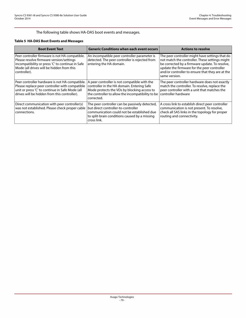
Avago Technologies- 79 -
Syncro CS 9361-8i and Syncro CS 9380-8e Solution User GuideOctober 2014
Chapter 4: Troubleshooting Event Messages and Error Messages
The following table shows HA-DAS boot events and messages.
Table 5 HA-DAS Boot Events and Messages
Boot Event Text Generic Conditions when each event occurs Actions to resolve
Peer controller firmware is not HA compatible. Please resolve firmware version/settings incompatibility or press 'C' to continue in Safe Mode (all drives will be hidden from this controller).
An incompatible peer controller parameter is detected. The peer controller is rejected from entering the HA domain.
The peer controller might have settings that do not match the controller. These settings might be corrected by a firmware update. To resolve, update the firmware for the peer controller and/or controller to ensure that they are at the same version.
Peer controller hardware is not HA compatible. Please replace peer controller with compatible unit or press 'C' to continue in Safe Mode (all drives will be hidden from this controller).
A peer controller is not compatible with the controller in the HA domain. Entering Safe Mode protects the VDs by blocking access to the controller to allow the incompatibility to be corrected.
The peer controller hardware does not exactly match the controller. To resolve, replace the peer controller with a unit that matches the controller hardware
Direct communication with peer controller(s) was not established. Please check proper cable connections.
The peer controller can be passively detected, but direct controller-to-controller communication could not be established due to split-brain conditions caused by a missing cross link.
A cross link to establish direct peer controller communication is not present. To resolve, check all SAS links in the topology for proper routing and connectivity.
Avago Technologies- 80 -
Syncro CS 9361-8i and Syncro CS 9380-8e Solution User GuideOctober 2014
Revision History Version 2.0, October 2014
Revision History
Version 2.0, October 2014
Removed Section 4.2.2 about verifying dual-ported SAS addresses in the Ctrl-R utility.
Removed Sections 1.7.1 and 1.7.2.
Version 1.0, August 2014
Initial release of this document.