synthesis and structures of new three-dimensional copper
TRANSCRIPT

Western Kentucky UniversityTopSCHOLAR®
Masters Theses & Specialist Projects Graduate School
12-2013
Synthesis and Structures of New Three-Dimensional Copper Metal-Organic FrameworksNitin Kumar PallyWestern Kentucky University, [email protected]
Follow this and additional works at: http://digitalcommons.wku.edu/theses
Part of the Analytical Chemistry Commons, Inorganic Chemistry Commons, and the MaterialsChemistry Commons
This Thesis is brought to you for free and open access by TopSCHOLAR®. It has been accepted for inclusion in Masters Theses & Specialist Projects byan authorized administrator of TopSCHOLAR®. For more information, please contact [email protected].
Recommended CitationPally, Nitin Kumar, "Synthesis and Structures of New Three-Dimensional Copper Metal-Organic Frameworks" (2013). Masters Theses& Specialist Projects. Paper 1295.http://digitalcommons.wku.edu/theses/1295


SYNTHESIS AND STRUCTURES OF NEW THREE-DIMENSIONAL COPPER METAL-ORGANIC FRAMEWORKS
A Thesis Presented to
The Faculty of the Department of Chemistry Western Kentucky University
Bowling Green, Kentucky
In Partial Fulfillment Of the Requirements for the Degree
Master of Science
By Nitin Kumar Pally
December 2013

I dedicate this thesis to my family, friends and to my research advisor Dr. Bangbo Yan
who supported and encouraged me the most during my challenging times here at Western
Kentucky University

iv
ACKNOWLEDGMENTS I wish to express my hearty thanks and appreciation for the contribution and help
of the many people who made this work possible. I would like thank my parents Devadas
Pally and Nirmala Pally for their support and guidance; Dr. Bangbo Yan, for
his everlasting support and patience; Dr. Yan Cao, for helping me for the analysis of
materials for my research; Dr. Cathleen Webb, for giving me the right advice in order to
accomplish my goals; Ms. Alicia McDaniel, for her support and help; Ms. Dara Craver
and Ms. Aly Anderson for always helping me and making things easier and enjoyable. I
would like to thank my research group members Raj Kishore Vakiti and Brady Garabatto
for their support and suggestions.
I would like to especially thank Dr. Bangbo Yan, for giving me an opportunity to
work in his research group and for providing such a good research project. He supported
me until the completion of my research. Nothing was possible without his
blessings, support and encouragement throughout this journey.

v
TABLE OF CONTENTS List of Figures ................................................................................................................... vi
List of Tables .................................................................................................................... ix
Abstract .............................................................................................................................. x
Chapter One: Introduction ................................................................................................. 1
References ........................................................................................................................ 14
Chapter Two: Materials and Methods .............................................................................. 18
References ........................................................................................................................ 29
Chapter Three: Results and Discussions .......................................................................... 30
References ........................................................................................................................ 53
Chapter Four: Conclusion ................................................................................................ 54
Appendix .......................................................................................................................... 55

vi
LIST OF FIGURES
Figure 2.1 (a) The parts of an autoclave; (b) The entire setup of the autoclave. ............. 19
Figure 2.2 Bruker Quazar Diffractometer ........................................................................ 21
Figure 2.3 Leco- True-Spec CHN Determinator ............................................................. 22
Figure 2.4 Perkin-Elmer LS55 Fluorescence Spectrophotometer ................................... 23
Figure 2.5 Cary 100 UV-vis Spectrophotometer ............................................................. 24
Figure 2.6 Perkin-Elmer Spectrum One FTIR ................................................................. 25
Figure 2.7 TA Q5000 Thermogravimetric analyzer ........................................................ 26
Figure 3.1 3D view of the framework .............................................................................. 35
Figure 3.2 View of coordination geometry of (a) Cu(1) ion (b) Cu(2) and Cu(3) ions ... 36
Figure 3.3 (a) Chain of {Cu2(pz)}; (b) Chain of {Cu2(btc)}; (c) doubled layer
formation of {Cu2(pz)(Cu2(btc))2} with {Cu2(pz)}(black chain) and {Cu2(btc)}(red
chain); (d) 3D framework showing double layered {Cu2(pz)(Cu2(btc))2} connected
by pz ligands(purple) ....................................................................................................... 37
Figure 3.4 View of pores along a-axis ............................................................................. 38
Figure 3.5 View of pores along ab plane ......................................................................... 39
Figure 3.6 Coordination environments of different Cu ions within the framework ........ 40
Figure 3.7 Bond length for various Cu-O bonds.............................................................. 41
Figure 3.8 View of the porous framework along c-aixs .................................................. 41
Figure 3.9 Three dimensional view of the framework showing the 3D porous net(red)
interconnected with 2D hexagonal net (blue) .................................................................. 42
Figure 3.10 Structure of Cu2(RCO2)4 unit within the framework .................................... 44

vii
Figure 3.11 Packing of the framework with copper tetracarboxylate groups along c-axis
.......................................................................................................................................... 44
Figure 3.12 Compound 3 viewed along the cell body ..................................................... 45
Figure 3.13 Layer formations in compound 4 with atomic labelling .............................. 46
Figure 3.14 Packing diagram of the structure of 4 along a-axis ...................................... 47
Figure 3.15 Chain formations of compound 4 along c-axis............................................. 48
Figure 3.16 View of the coordination center of Cu with atomic labeling ....................... 49
Figure 3.17 View of pores along ab plane ....................................................................... 49
Figure 3.18 Thermogravimetric analysis of compound 1 ................................................ 50
Figure 3.19 Infrared spectra for compound 1 .................................................................. 51
Figure 3.20 The emission spectra of compound 1 ........................................................... 52

viii
LIST OF TABLES
Table 1.1 List of various MOFs presented in the literature ............................................. 12
Table 2.1 Chemical materials .......................................................................................... 18
Table 3.1 Table showing synthetic procedures ................................................................ 30

ix
SYNTHESIS AND STRUCTURES OF NEW THREE-DIMENSIONAL COPPER METAL-ORGANIC FRAMEWORKS
Nitin Kumar Pally December 2013 64 Pages Directed by: Dr. Bangbo Yan, Dr. Yan Cao and Dr. Chad Snyder Department of Chemistry Western Kentucky University Metal-organic frameworks (MOFs) are crystalline materials with metal ions
covalently bonded to organic ligands. The ligands act as spacers often creating a porous
structure with very high pore volume and surface area. MOFs are known for their robust
structures, high porosity, and different chemical functionalities and are considered for
applications in adsorptions, separations, catalysis and gas storage. This work focuses on
the synthesis of new MOFs using copper compounds. Different types of carboxylate
ligands were used for the synthesis. Two new copper-organic frameworks,
[Cu3(pyz)(btc)] (1), and [(Cu3(btc))•xH2O] (2) (btc= benzene-1,3,5-tricarboxylate, pyz=
pyrazine) have been synthesized using hydro/solvothermal methods and have been
characterized using X-ray diffraction, IR, TGA, fluorescence and CHN analysis.

1
CHAPTER ONE
INTRODUCTION
The objective of this project is to synthesize new metal-organic frameworks (MOFs)
using copper (I) ion and to study their structures and properties. MOFs are porous
structures with metal ions covalently bonded to organic ligands. Due to their robust
structure, high porosity and different chemical functionalities,1 they have received
increasing attention in the field of inorganic chemistry for further research by many
groups. This chapter covers the basic background of MOFs and their applications. It
focuses on MOFs which are built from copper ions and organic ligands.
1. Applications
MOFs have shown potential applications in gas separation, gas adsorption and
catalysis.1-7 The past 20 years have seen remarkable progress in the design, synthesis and
characterization of MOFs owing to their enormous structural and chemical diversity and
their potential applications. The intense current research efforts towards industrial
applications are mostly attributed to their unique structural properties such as robustness,
high thermal and chemical stabilities, unprecedented internal surface areas and high pore
volumes which can be maintained upon evacuation of guest molecules from the pores.
Biomedical applications
Huge numbers of promising drug candidates have been abandoned due to their poor
bioavailability because the controlled delivery of the drug4 to where it is needed cannot
be achieved. Non-toxic and biodegradable MOFs have been shown to be suitable for the

2
encapsulation and controlled delivery of a large number of therapeutic molecules,
including several challenging antitumor and antiretroviral drugs.2
The MOF skeleton can sometimes be flexible.6 These frameworks combine a high
pore volume, a regular porosity and the presence of tunable functional organic groups
which allow an easy modulation of the size of pores. Due to these features, MOFs are
termed as 'hybrid route' for drug delivery. By tailoring the pore sizes of the frameworks,
large storage capacities and longer release time can be achieved for specific drug
molecules. To consider a MOF as a potential drug carrier, it must have high drug loading
capacity, efficient delivery, control over the release of the drug, and matrix degradation
within the body.
MOFs such as MIL-100 and MIL-1013 have been used for studying the adsorption of
the drug Ibuprofen. They exhibited a very high drug storage capacity, up to an
unprecedented 1.4 g of the drug per gram of porous solid and had a complete drug
controlled release under physiological conditions from 3 to 6 days.
Other MOFs such as MIL-53, MIL-88 series and MIL-89 offers many possibilities to
achieve an adequate controlled release of various pharmacological molecules.3-5
Chemical Sensors
Sensitivity, selectivity, response time, material stability and reusability are important
elements to consider in optimizing the performance and utility of chemical sensors.
MOFs having luminescent properties together with size/shape selective sorption
properties can be considered as potential sensing devices.7-12 The presence of linkers or
ligands in the frameworks is beneficial as the linkers contain aromatic subunits which are
readily luminesce following UV or visible (typically blue) excitation.11

3
The potential selectivity of MOF material for a specific analyte or classes of analytes
is substantial but not highly developed because MOFs tend to adsorb atoms or molecules
which are smaller than the aperture size.8-9 It has been generally assumed that open metal
sites will play a crucial role in molecular recognition processes owing to their ability to
impart highly selective and specific molecular transformations, transport and storage.9
Catalysis
The structural nanoporosity of MOF materials places them at the frontier of zeolites
and surface metal organic catalysts.13a MOFs, therefore, appear to be excellent candidates
for catalysis with the understanding of their potential still largely in its infancy.
HKUST-1 contains large cavities having windows of diameter equal to 6 Å.13b The
coordinated water molecules are easily removed leaving open metal (Cu) sites. Kaskel
and co-workers showed that these Lewis acid sites in HKUST-1 could catalyze the
cyanosilyation of benzaldehyde.14 Ferey and co-workers have reported the catalytic
activity of two different MIL-100 (Fe, Cr) for Friedel-Crafts benzylation. Reports
indicated that Fe3+ catalyst showed higher catalytic activity than Cr3+ catalyst despite
having similar structures.15
Gas Separations
Porous solids acting as adsorbents or membrane fillers are playing key roles in
separations and purifications of various chemical mixtures. MOFs are potential materials
for gas separations due to their high surface area, adjustable pore sizes and controllable
surface properties. Upon comparison with other porous material such as zeolites, MOFs
are advanced in terms of rigidity/flexibility, variety and design ability in structures and
properties. MOFs have an advantage in separations as they can be regenerated under mild

4
conditions compared to zeolites. The application of gas separation is mostly required
when one gas is harmful in a mixture of gases. For CO2/CH4 mixture, it is important to
separate CO2 from CH4 from natural gases as it is harmful to environment.26
Techniques used for the separation using MOFs are adsorptive separations (mostly
selective adsorption), membrane separations and pressure/temperature swing adsorption.
Membrane separation technologies are used to attain high efficiency for CO2 capture
owing to their selective extractions of CO2 from mixed gas streams, their low energy
requirements and the flexibility.27 For gas separations, membrane selectivity depends on
the relative sizes of gas molecules and the relative condensability of the gas molecules.29
Fine tuning the interactions between the gases and polymeric membranes is required to
increase the selectivity between similarly sized molecules.
Gas Storage
The high pore volume of MOFs provides substantial spaces for storage of gases. Most
of the research conducted on MOFs for gas storage was done on CO2 and H2.32 Owing to
their flexibility to design through control of the architecture and chemical functionability
of the pores, MOFs have emerged as a new family of nanoporous materials with
promising applications for gas storage.
CO2 capture and storage from flue exhaust plays a significant role in mitigating its
effect on climate change. The removal of CO2 for natural gas upgrade or hydrogen
purifications is of economic importance. Compared to other techniques such as carbon
capture and separation, amine adsorption of CO2, etc., MOFs are better compatible in
storing CO2 and are economic.35-36 These materials can be synthesized easily and the
yield is of high purity and high crystalline structures.

5
Hydrogen gas is a potentially renewable source of energy due to its high energy
content and clean combustion. MOFs are considered for the storage of H2 gas due to their
physical sorption properties and high specific surface area. Metal centers within the
frameworks having high binding energies can be bonded directly to hydrogen gas.
Sequestering H2 inside flexible frameworks showed hysteric adsorption behavior but the
hydrogen storage capacity of the framework decreased with increasing temperatures.37
MOFs can be synthesized with selected metal centers in large numbers thereby allowing
low binding energy for hydrogen to bind with the metal centers at room temperature.38
MOF-5, which is a cubic Zn-teraphtalate based framework, is known to be air-
sensitive, has hydrogen gas sorption capacities decreasing upon exposure to air. It has a
BET surface area of 3800 m2g-1 and adsorbs excess 7.1 wt % of H2 at 40 bar and 77 K,
and is still considered to be one of the best hydrogen storage materials. This amount
increased to 10 wt% at 100 bar which corresponds to the volumetric storage density of 66
gL-1. Although MOF-5 shows high storage capacity at 77 K, it does not show a good
uptake at 298 K due to weak interactions between H2 and the framework.39
2. Synthesis
The synthesis of MOFs can be conventionally achieved by employing a synthetic
modular design wherein the metal ions and organic ligands are combined to afford a
crystalline, porous network. A large variety of synthetic methods have been developed in
recent years for the preparation of these frameworks and the conditions that lead to the
formation of the desired phases are widely variable. The reported procedures have a wide
range of temperatures, solvent compositions, reagent concentrations and ratios, and

6
reaction times. Mostly the hydro/solvothermal procedures are used for effective synthesis
of frameworks. Due to this procedure, the solvent molecules occupy the void spaces
within the framework and can be removed either by heating to high temperatures or with
application of vacuum. The removal of the solvent molecules may cause large pore
volumes and create large surface areas in the frameworks.
Organic Ligands
Organic ligands are known for their complex nature and ability to form coordination
bonds. They exist mostly in anionic states and, thus, are helpful in forming bonds with
metal ions. The most commonly used organic ligands in making MOFs are benzene
1,3,5-tricarboxylic acid(H3btc), benzene 1,4-dicarboxylic acid(H2bdc), 4,5-imidazole
dicarboxylic acid(H2idc) and pyrazine 2-carboxylic acid(Hpzc).40 The main advantages of
organic ligands are their rigidity and tendency to form metal clusters when they are
coordinately bonded to metal ions.
Some organic anions are capable of directing the crystallization of supramolecular
entities through either cation-anion interactions or hydrogen bonding interactions
between an organic host and an anionic guest. As a multidentate ligand, the pyrazine 2-
carboxylate (pzc) anion has shown its potential to link metal ions into coordination
polymers.42 The pzc ligand and its substituted derivatives have proven to be extremely
versatile for the construction of mixed-metal framework structures because of their
ability to engage in several different coordination modes. In framework structures
synthesized from pzc based ligands, the cavity dimensions are limited by the length of the
pyrazine ring.

7
The ubiquitous functional group for the synthesis of coordination polymers is the
pyridyl group. The lone pair of electrons on the nitrogen can be readily donated to a
metal center to form a ligand-metal linkage. Usage of combination of two functional
groups in single ligands such as pzc results in the formation of mono, bi-metallic
multivalent organic-inorganic hybrid materials.
Pyrazine 2-carboxylic acid
The variety of available carboxylic acids leads to a large number of frameworks with
tunable properties. Either neutral molecules or anions of di-, tri-oligocarboxylic acids are
used as organic linkers between the knots (metal ions or metal-oxo clusters). The tri-
anion of H3btc acid plays an important role in the field of MOFs.48 Many applications of
MOFs, in particular their use as hydrogen storage devices, require thermally stable
frameworks. Thus, heat of sorption, which is produced during the charging of the
materials, must not lead to a damage of the skeleton, and thermal processing of the
compounds needs to be possible. The low stability of carboxylates towards heat is a
significant disadvantage, because it limits their applicability as linkers.

8
Benzene 1,3,5-tricarboxylic acid Benzene 1,4-dicarboxylic acid
Solvents & Temperature
The syntheses of the MOFs are done by hydro/solvothermal method which uses
solvents for the purpose of dissolving reactants. Pure solvents or mixture of solvents can
be used. Mostly organic solvents such as dimethyl formamide (DMF), acetonitrile,
ethanol are used.
The solutions containing the reactants are kept in Teflon cups in an autoclave for
faster processing. The autoclave is allowed to run for few hours to several days to allow
crystal growth depending on the rate of reaction. Usually high temperatures (160- 240°C)
are used for running the reactions in autoclaves. Low temperatures ranging from 25-
120°C can be used for reactions containing pure organic solvents which are volatile.1-4
The frameworks contain coordinated solvent molecules in their pores which are
removed to give porous materials and the empty spaces within the MOF form unsaturated
open metal sites. These unsaturated open metal sites and large pores are helpful in
various applications such as gas adsorption and gas separation.

9
3. Copper based MOFs
Copper (II) based MOFs using BTC
HKUST-1 is one of the most well characterized and widely studied MOFs for its
potential use in industrial applications due to its relatively easy synthesis and excellent
textural and physicochemical properties. HKUST-1, was reported by Chui et al. in
1993.44 It is synthesized from Cu(NO3)2 and H3btc in the presence of water and ethanol.
The copper ions are coordinated via carboxylate groups to form a so-called paddle wheel
unit in a three-dimensional porous cubic network. The crystal is comprised of 12 water
molecules per pore. The water molecules bonded with Cu2+ sites can be removed from
the framework to leave open metal sites. It holds good stability against moisture and has
thermal stability.
Compared to other MOFs, HKUST-1 can adsorb greater amount of H2 gas at low
pressures.50-52 HKUST-1 was also used as catalyst due to its rigid and stable framework
containing free coordination Cu(II) open metal sites orientated towards the center of the
pores.
Functionalization of MOF ligands have impacted the adsorption properties of the
framework and also provide sites for postsynthetic modifications. H3btc can be alkylated
with methyl (MBTC = methyl -1,3,5- benzene tricarboxylate) and ethyl (EBTC = ethyl-
1,3,5- benzene tricarboxylate) groups and new isostructural copper-frameworks were
synthesized.54 These new MOFs do not have similar topology as HKUST-1, but do
possess similar open metal sites and porosity. The amounts of CO2 and CH4 adsorption
have increased, due to the increased Vander waals interactions between the ligands
within the framework.

10
Apart from HKUST-1, other MOFs were synthesized using mixed ligands such as
H3btc and 2,2′-biyridine, [Cu2(OH)(2,2'-bipy)2(btc)3•2H2O].52 The presence of two
ligands limited the pore size, thereby, allowing only comparatively small and polar
solvent molecules to access the channel or interact with the surface of the material.
Using copper compounds and H3btc many other frameworks have been synthesized such
as [Cu3(btc)2(NH3)6(H2O)3]64 where the two-dimensional (2D) copper-btc framework
showed antiferromagnetic properties due to presence of ammonia molecules within the
framework. Another framework synthesized using copper, H3btc and ammonia is
[Cu3(btc)2(H2O)3(NH3)4]•2H2O,65 a 2D threefold interpenetration network with pores in
the framework.
Mixed metal frameworks having copper and btc have been synthesized by various
research groups using s-block metals such as sodium. [NaCu{C6H3(COO)3}(H2O)4]
•2H2O is a one-dimensional (1D) network containing zig-zag chains of btc bonded to
Cu2+ ions which were connected in a 2D double sheet network via sodium ions and
bridging aqua ions.
A new three-dimensional (3D) Porous Cu(II)–btc coordination polymer,
[Cu2(OH)(btc)(H2O)]n•2nH2O was synthesized by changing the reactant ratio compared
to HKUST-1. 67
Copper(II) frameworks using pyrazine-2-carboxylic acid
Pyrazine-2-carboxylic acid (Hpzc) incorporates both aspects of the pyrazine and
carboxylate functionalities. The presence of carboxylate group on the pyrazine ring gives
the chealting effect. Copper-pzc (Cu(pzc)2) polymers are synthesized under hydrothermal
conditions to form zero-dimensional (0D) metal complexes.46

11
Cu(pzc)2 building blocks can be used for the synthesis of Cu mixed metal polymers
with the general formula [M(pzc)2M'A], where M'= second metal and A= monovalent
ion. Copper along with cadmium was used to synthesize [Cu(pzc)2(H2O)2Cd2Cl4(H2O)]
frameworks as a 1D polymer.50 The polymer exhibited Cu-Cd hydrogen bonding between
the bound water molecules.
Copper forms mixed valent compounds such as [Cu(I)Cu(II)(pca)2(H2O)(ClO4)]51 and
[Cu(I)Cu(II)(pzc)2(NO3)(H2O)].52 In these compounds the pca ligand has chealting effect
on the divalent Cu centers. In both the compounds Cu(pzc)2 units are connected to the
Cu(I) centers generating 1D chains.
Copper(I) based MOFs
Copper(I) complexes occupy a significant place in the chemistry of coordination
compounds and in the development and evolution of homogeneous metal-complex
catalysis. Cu(I) porous MOFs with permanent porosity and different solvent sorption
properties have been documented.54-56 Pyrazine and pyridine derivative linkers have been
used along with Cu(I) to stabilize Cu in aqueous solutions.56 These derivatives have been
used extensively for fabrication of versatile MOFs with Cu(I).
Most of the Cu(I) frameworks are synthesized through hydrothermal method to
produce 1, 2, or 3D frameworks. Cu(I) can combine with other mono and bivalent ions
such as Cu(II), Fe(II) and Ag(I) to form porous MOFs with varied functionalities.59-60
Copper acetate along with 4,4′-bipyridine and 1,2-ethandisulfonic acid were used to
synthesize the framework Cu2(4,4′-bipy)2 (O3SCH2CH2SO3)·3H2O, which was termed as
SLUG-22. 63 This framework was yellow and the Cu(II) was reduced to Cu(I) during the
hydrothermal synthesis. SLUG-22 is a cationic 1D MOF with infinite chains composed

12
of alternating copper (I) centers and 4,4′-bipy organic linkers. The Cu(I)-bipy chains are
arranged into close-packed layers by π-π stacking between adjacent 1D chains. The
distance between the adjacent Cu(I)-bipy chains is ca. 3.466 Å, which is in the reasonable
range of π-π stacking distance and leads to a cationic layer.
There are two examples of 3D MOFs containing Cu(I): {[Cu4I3(DABCO)2]I3}
(DABCO=N,N’-dimethyl-1,4-diazabicyclo[2.2.2]octane), {Fe(3-Xpy)2[Cu(3-
Xpy)z(CN)2]2} (3-Xpy = 3-halogenpyridine).
{[Cu4I3(DABCO)2]I3}:59 Copper chloride and periodic acid along with sodium
perchlorate and C6H12N2·6H2O [DABCO] were used for the synthesis of the Cu(I)
framework under solvothermal conditions. The crystal structure contains a cationic
framework which is constructed from bidentate organic ligands DABCO and [Cu8I6]2+
clusters. Within the framework, the channels are occupied by I2 and I−. The guest I2
molecules can move freely in and out of the host-framework and the guest I− can be
exchanged by SCN− so the compound exhibits iodine release/adsorption and ion-
exchange properties. The charged cluster [Cu8I6]2+ is composed of eight Cu atoms and six
I atoms, forming a rhombic dodecahedron. The Cu atom is coordinated in distorted
tetrahedral geometry by three μ4-I atoms and one N atom from the ligand DABCO.
{Fe(3-Xpy)2[Cu(3-Xpy)2(CN)2]2}:60 This framework is a cyanide-bridged iron(II)-
copper(I) bimetallic coordination polymer. It is synthesized under solvothermal
conditions using FeCl2•4H2O and CuCl2•2H2O and KCN. 3-Xpy ligands (X=F, Cl, Br,
and I) were used for the synthesis for the frameworks. A list containing all the
frameworks present within the literature is shown in Table 1.1.

13
Table 1.1 List of various frameworks present in literature.
S.No Formula Framework Application Ref
1. [Cu3(MBTC)2(H2O)3]n 3D Gas Adsorption
50
2. [Cu3(EBTC)2(H2O)3]n 3D Gas Adsorption
50
3. (CTA)1[Cu46(C9H3O6)24-(OH)12](PW12O40)3•xH2O
3D 51
4. Cu3-x Znx(btc)2 3D Catalytic activity
52
5. [Cu2(OH)(2,2′-bipy)2(btc)32H2O]n 2D Selective catalyst
53
6. Cu2(4,4′-bipy)2 (O3SCH2CH2SO3) •3H2O
1D Anion Exchange
59
7. [CuI2(cis-L1)2][CuI
2(trans- L1)2Mo6O18(O3AsPh)2] (L1 = 1,3-bis(1,2,4-triazol- 1-yl)propane
2D Photocatalyst 58
8. [Cu2(OH)(btc)(H2O)]n •2nH2O
3D 67
9. [NaCu{C6H3(COO)3}(H2O)4] •2H2O
1D 66
10. [Cu3(btc)2(NH3)6(H2O)3]
2D 64
11. [Cu3(btc)2(H2O)3(NH3)4]n •2H2O
2D 65

14
REFERENCES
1. (a) Zhao, D.; Yuan, D.; Zhao, H. C. Energy Environ, Sci. 2008, 1, 597. (b) Ferey, G.
Studies in Surface Science and Catalysis. 2007, 170A, 66. (c) Yaghi, O. M. Nature
Mater. 2007, 6, 92. (d) Roswell, J. L. C.; Yaghi, O. M. Micropor Mesopor Mater. 2007,
73, 3. (e) Brammer, L. Chem. Soc. Rev. 2004, 33, 476. (f) Braga, D. Chem. Commun.
2003, 2751.
2. Horcajada, P.; Chalati, T.; Serre, C.; Gillet, B.; Sebrie, C.; Baati, T.; Eubank, J. F.;
Heurtaux, D.; Gref, R. Nature Mater. 2010, 9, 172.
3. Horcajada, P.; Serre, C.; Maurin, G.; Ramsahye, A. N.; Balas, F.; Sebban, M.;
Taulelle, F.; Ferey, G. J. Am. Chem. Soc. 2008, 130, 6774.
4. (a) Freiberg, S.; Zhu, X. X. Int. J. Pharmacol. 2004, 282, 1. (b) Soppimath, K. S.;
Aminabhavi, T. M.; Kulkarni, A. R.; Rudzinski, W. W. J. Controlled Release. 2001, 70,
1.
5. Horcajada, P.; Serre, C.; Vallet-Regi, M.; Sebban, M.; Taulelle, F.; Ferey, G. Angew.
Chem. Int. Ed. 2006, 45, 5974.
6. Uemura, K.; Kitagawa, S.; Kondo, M.; Fukui, K.; Kitaura, R.; Chang, H. C.; Mizutani,
T. Chem. Eur. J. 2002, 8, 3586.
7. Chen, B.; Yang, Y.; Zapata, F.; Lin, G.; Qian, G.; Lobkovsky, B. E. Adv. Mater. 2007,
19, 1693.
8. Yaghi, O. M.; Davis, C. E.; Li, G.; Li, H. J. Am. Chem. Soc. 1997, 119, 2861.
9. Reineke, T. M.; Eddaoundi, M.; Fehr, M.; Kelley, D.; Yaghi, O. M. J. Am. Chem. Soc.
1999, 121, 1651.
10. Ferey, G. Chem. Mater. 2001, 13, 3084.
11. Kim, J.; Chen, B.; Reineke, T. M.; Li, H.; Eddaoundi, M.; Moler, D. B.; O'Keeffe,
M.; Yaghi, O. M. J. Am. Chem. Soc. 2001, 123, 8329.
12. Yang, S. Y.; Long, L. S.; Jiang, Y. B.; Huang, R. B.; Zheng, L. S. Chem. Mater.
2002, 14, 3229.
13. (a) Hoskins, B. F.; Robson, R. J. Am. Chem. Soc. 1990, 112, 1546. (b) Chui, S. S. Y.;
Lo, S. M. F.; Charmant, J. P. H.; Orpen, A. G.; Williams, I. D. Science. 1999, 283, 1148.

15
14. Schlichte, K.; Kratzke, T.; Kaskel, S. Micropor Mesopor Mater. 2004, 73, 81.
15. Horcajada, P.; Surble, S.; Serre, C.; Hong, D. Y.; Seo, Y. K.; Chang, J. S.;
Margiolaki, I.; Ferey, G. Chem. Commun. 2007, 2820.
16. Fujita, M.; Kwon, Y. J.; Washizu, S.; Ogura, K. J. Am. Chem. Soc. 1994, 116, 1151.
17. Abney, L.; Ma, C.; Lin, W. Chem. Soc. Rev. 2009, 38.
18. Ngo, H. L.; Hu, A.; Lin, W. J. Mol. Catal. A: Chem. 2004, 215, 177.
19. Cho, S. H.; Gadzikwa, T.; Afshari, M.; Nguyen, T.; Hupp, J. T. Eur. J. Inorg Chem.
2007, 4863.
20. Hasegawa, S.; Horike, S.; Matsuda, R.; Furukawa, S.; Mochizuki, K.; Kinoshita, Y.;
Kitagawa, S. J. Am. Chem. Soc. 2007, 129, 2600.
21. Xiao, B.; Hou, H.; Fan. Y. J. Organomet. Chem. 2007, 692, 2014.
22. DeRosa, S.; Giordano, G.; Granato, T.; Katovic, A.; Siciliano, A.; Tripicchio, F.;
Agric, A. Food Chem. 2005, 3, 8306.
23. Gomez-Lor, B.; Gutierrez-Puebla, E.; Iglesias, M.; Monge, M.; Ruiz-Valero, C.;
Snejko, N. Inorg. Chem. 2002, 41, 2429.
24. Rowsell, J. L. C.; Millward, A. R.; Park, K. S.; Yaghi, O. M. J. Am. Chem. Soc. 2004,
126, 5666.
25. Panella, B.; Hirscher, M.; Putter, H.; Muller, U. Adv. Funct. Mater. 2006, 16, 520.
26. Karger, B. L.; Snyder, L. R.; Horvath, C. An Introduction to Separation Science,
Wiley, New York. 1973.
27. Mueller, U.; Hesse, M.; Puetter, H.; Kamieth, M.; Schierle, A. Patent, WO
2006072573 A2. 2006.
28. Li, J. R.; Kuppler, R. J.; Zhou, H.C. Chem. Soc. Rev. 2009, 38, 1477.
29. Mueller, U.; Schubert, M.; Teich, F.; Puetter, H.; Schierle-Arndt, K.; Pastre, J. J.
Mater. Chem. 2006, 16, 626.
30. (a) Zuttel, A.; Naturwissenschaften. 2004, 91, 157. (b) Seayad, A. M.; Antonelli, D.
M. Adv. Mater. 2004, 16, 765. (c) Sakintuna, B.; Lamari-Darkrim, F.; Hirscher, M. Int. J.
Hydrogen Energy. 2007, 32, 1121. (d) Orimo, S, I.; Nakamori, Y.; Elisco, J. R.; Zuttel,
A.; Jensen, C. M. Chem. Rev. 2007, 107, 4111.
31. Liu, Y.; Kabbour, H.; Brown, C. M.; Neumann, C. C. Langmuir. 2008, 24, 4772.

16
32. Electric Power Research Institute, Program on Technology Innovation: post-
combustion CO2 Capture Technology Development, Electric Power Research Institute,
Palo Alto. 2008.
33. Batten, S. R.; Robson, R. Angew. Chem. Int. Ed. 1998, 110, 1558;
34. Ferey, G. Dalton Trans. 2009, 4400.
35. Ferey, G. Chem. Soc. Rev. 2008, 37, 191.
36. Fischer, R. A.; Woll, C. Angew. Chem. Int. Ed. 2008, 47, 8164.
37. Cheon, Y. E.; Suh, M. P. Chem. Commun. 2009, 45, 2296.
38. (a) Chui, S. S. Y.; Lo, S. M. F.; Charmant, J. P. H.; Orpen, A. G.; Williams, I. D.
Science. 1999, 283, 1148. (b) Panella, B.; Hirscher, M.; Putter, H.; Muller, U. Adv. Funct.
Mater. 2006, 16, 520.
39. Kaye, S. S.; Dailly, A.; Yaghi, O. M.; Long, J. R. J. Am. Chem. Soc. 2007, 129,
14176.
40. Bianchi, G.; Garcia-Espana, E.; Bowman-James, K. Supramolecular Chemistry of
Anions; Wiley- VCH: Wienheim. 1997.
41. Hagrman, D.; Zubieta, C.; Rose, D. J.; Zubieta, J.; Haushakter, R. C. Angew. Chem.
Int. Ed. 1997, 36, 873.
42. Klein, C. L.; Majeste, R. J.; Trefonas, L. M.; O'Connor, C. J. Inorg. Chem. 1982, 21,
1891.
43. Zheng, L. M.; Wang, Y. S.; Wang, X. Q.; Korp, J. D.; Jacobson, A. J. J. Inorg. Chem.
2001, 40, 1380.
44. Chen, C. L.; Goforth, A. M.; Smith, M. D.; Su, C. Y.; zur-Loye, H. C. Angew. Chem.
Int. Ed. 2005, 44, 6673.
45. Li, S. Z.; Ma, P. T.; Wang, J. P.; Guo, Y. Y.; Niu, H. Z.; Zhao, J. W.; Niu, J. Y. Cryst.
Eng. Comm. 2010, 12, 1718.
46. Tranchemontagne, D. J.; Mendoza-Cortes, J. L.; O'Keeffe, M.; Yaghi, O. M. Chem.
Soc. Rev. 2009, 38, 1257.
47. Morris, R. E.; Wheatley, P. S. Angew. Chem. Int. Ed. 2008, 47, 4966.
48. Czaja, A. U.; Trukhan, A. U.; Muller, U. Chem. Soc. Rev. 2009, 38, 1284.
49. Sun, X.; You, W.; Cheng, H.; Zhang, F.; Meng, B.; Zhang, L. Inorg. Chim. Acta.
2011, 373, 137.
17
50. Krawiec, P.; Krammer, M.; Sabo, M.; Kunschke, R.; Frode, H.; Kaskel, S. Adv. Eng.
Mater. 2006, 8, 293.
51. Liu, C. M.; Zhang, D. Q.; Luo, N. L.; Wang, N. L.; Hu, H. M.; Zhu, D. M. Eur. J.
Inorg. Chem. 2003, 3618.
52. Fan, G.; Xie, G.; Chen, S. P.; Gao, S. L.; Shi, Q. Z. J. Coord. Chem. 2003, 56, 1351.
53. Sun, C.; Liu, S.; Liang, D.; Shao, K.; Ren, Y.; Su, Z. J. Am. Chem. Soc. 2009, 131,
1883.
54. Cai, Y.; Zhang, Y.; Huang, Y.; Marder, S.; Walton, K.S. Cryst. Growth. Des. 2012,
12, 3709.
55. Wee, L.; Wiktor, C.; Turner, S.; Vanderlinden, W.; Janssens, N.; Bajpe, S. R.;
Houthoofd, K.; Tendeloo, G. V.; Feyter, S. D.; Martens, J. A.; Kirschhock, C. E. A. J.
Am. Chem. Soc. 2012, 134, 10911.
56. Gul-E-Noor, F.; Jee, B.; Mendt, M.; Himsl, D.; Poppl, A.; Hartmann, M.; Haase, J.;
Krautscheid, H.; Bertmer, M. J. Phys. Chem. C. 2012, 116, 20866.
57. Song, L.; Jiang, C.; Jiao, C.; Zhang, J.; Sun, L.; Fen, X.; You, W.; Wang, Z.; Zhao, J.
Cryst. Growth Des. 2010, 12, 5020.
58. Mohapatra, S.; Maji, T. K. Dalton Trans. 2010, 39, 3412.
59. Fei, H.; Rogow, D. L.; Scott R. J. J. Am. Chem. Soc. 2010, 132, 7202.
60. Xin, B.; Zeng, G.; Lu, G.; Yun, L.; Xing, S.; Hua, J.; Li, G.; Shi, Z.; Feng, S. Dalton
Trans. 2013, 42, 7562.
61. Agusti, G.; Munoz, M. C.; Gaspar, A. B.; Real, J. A. Inorg. Chem. 2009, 8, 48.
62. Liu, B.; Yang, J.; Yang, G. C.; Ma, J. F. Inorg. Chem. 2013, 52, 84.
63. Fei, H.; Paw. U. L.; Rogow, D. L.; Bresler, M. R.; Abdollahian, Y. A.; Oliver, S. R. J.
Chem. Mater. 2010, 22, 2027.
64. Wang, X. F.; Zhang, X. L.; Zhou, X.; Li, J.; Kuang, Y-L.; Chen, J-H. J. Inorg. Gen.
Chem. 2012, 638, 1365.
65. Chen, W-X.; Wu, S.; Long, L-S.; Huang, R-B.; Zheng, L-S. Cryst. Growth Desg.
2007, 7, 1171.
66. Yin, C. S.; Siu, A.; Williams, I. D. Acta Cryst. 1999, C55, 194.
67. Chen, J.; Yu, T.; Chen, Z.; Xiao, H.; Zhou, G.; Weng, L.; Tu, B.; Zhao, D. Chem.
Letters. 2003, 32, 590.

18
CHAPTER TWO
MATERIALS AND METHODS
1. Materials
The chemicals used in this research project are listed in the table 2.1.
Table 2.1 Chemical materials
Name of the Chemical Formula Company name Grade
Benzene 1,3,5-tricarboxylic acid
C6H3(CO2H)3 Alfa Aesar 98%
Pyrazine 2-carboxylic acid C5H4N2O2 Alfa Aesar 98%
4,5-imidazole dicarboxylic acid
C5H4N2O4 Alfa Aesar 97%
Copper (II) Nitrate. trihydrate Cu(NO3)2 •3H2O
Fischer scientific Lab Grade crystals
Copper (I) Oxide Cu2O Alfa Aesar 99%
Copper (I) Chloride CuCl Alfa Aesar 99%
Tungstosilicic Acid hydrate H4[Si(W3O10)4] • xH2O
Alfa Aesar Reagent Grade
Sulfuric acid H2SO4 Fischer scientific 95.0 to 98.0 w/w %
Nitrogen gas N2 Air Gas Compressed
2. Solvo/Hydrothermal Methods
The solvo/hydrothermal method is a process of crystallization in which the compounds
are synthesized depending on the solubility of compound in water at autogenous pressure.
The crystallization process is done in a vessel called an autoclave. The autoclave is usually
made of thick-walled steel cylinders, which can withstand high temperatures and pressures
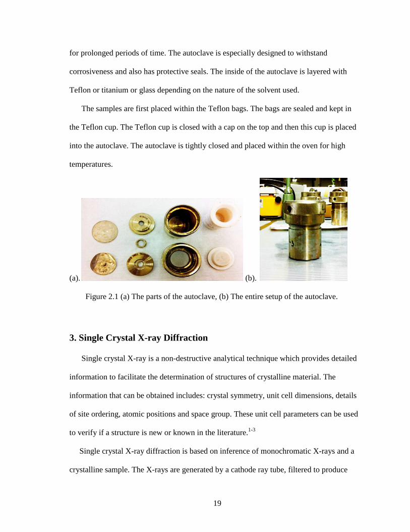
19
for prolonged periods of time. The autoclave is especially designed to withstand
corrosiveness and also has protective seals. The inside of the autoclave is layered with
Teflon or titanium or glass depending on the nature of the solvent used.
The samples are first placed within the Teflon bags. The bags are sealed and kept in
the Teflon cup. The Teflon cup is closed with a cap on the top and then this cup is placed
into the autoclave. The autoclave is tightly closed and placed within the oven for high
temperatures.
(a). (b).
Figure 2.1 (a) The parts of the autoclave, (b) The entire setup of the autoclave.
3. Single Crystal X-ray Diffraction
Single crystal X-ray is a non-destructive analytical technique which provides detailed
information to facilitate the determination of structures of crystalline material. The
information that can be obtained includes: crystal symmetry, unit cell dimensions, details
of site ordering, atomic positions and space group. These unit cell parameters can be used
to verify if a structure is new or known in the literature.1-3
Single crystal X-ray diffraction is based on inference of monochromatic X-rays and a
crystalline sample. The X-rays are generated by a cathode ray tube, filtered to produce

20
monochromatic radiation, collimated to concentrate and directed toward the sample. The
interaction of the incident rays with the sample produces constructive interference (and a
diffracted ray) when conditions satisfy Bragg's Law. This law relates the wavelength of
electromagnetic radiation to the diffraction angle and the lattice spacing in a crystalline
sample. These diffracted X-rays are then detected, processed and counted. By changing
the geometry of the incident rays, the orientation of the centered crystal and detector, all
possible diffraction directions of the lattice can be attained.
The instrument used for the single crystal X-ray diffraction analysis in this project is a
Bruker Quazar diffractometer. X-ray diffraction data for crystals were collected on a
Bruker Quazar diffractometer with an Apex II CCD detector. The data was processed with
the SAINT software4 and corrected for absorption with SAD-ABS.5 The structures were
solved by direct methods SHELXTL V.6.10 package6 and was refined against F2 by
weighted full-matrix least-squares calculations. All non-hydrogen atoms were refined
allowing for anisotropic displacement. Hydrogen atoms were localized from the difference
Fourier maps. Atomic scattering factors were taken from the International Tables for
Crystallography.7

21
Figure 2.2 Bruker Quazar Diffractometer
4. Carbon Hydrogen and Nitrogen Analyzer
The analyzer consists of a furnace capable of maintaining a temperature in the range to
ensure quantitative recovery of carbon, hydrogen and nitrogen and their corresponding
gases. The detection system helps in evaluating the gases present accurately.
The sample is induced into a hot furnace at a temperature of 1300ºC, the carbon is
converted into carbon dioxide, and the hydrogen in the compound is converted into water
vapor. These gasses are moved into a layer of adsorbent to trap the water vapor and it is
weighed to calculate the amount of hydrogen and the carbon dioxide is collected to
calculate the amount of carbon in the compound.

22
Figure 2.3 Leco True-Spec CHN Determinator
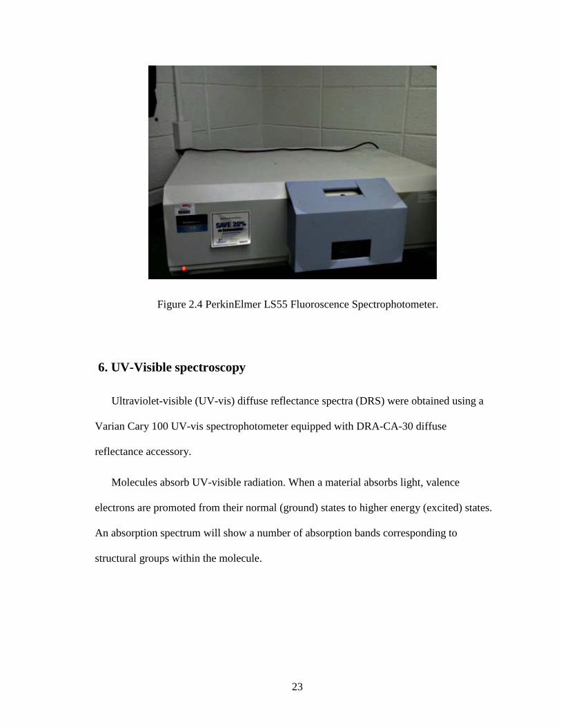
5. Fluorescence spectroscopy
The principle involved is that the atom is first excited by absorbing photons from the
ground electronic state to one of the various vibrational states in the excited electronic
state. The collisions between molecules cause the excited molecule to lose vibrational
energy until it reaches the lowest vibrational state of the excited electronic state. This loss
in energy is fluorescence and is observed using the Fluorescence spectroscopy.
PerkinElmer LS55 fluorescence spectrophotometer is used for the analysis.
Fluorescence spectroscopy is used in biochemical, medical and chemical research
fields for analyzing organic compounds.
23
Figure 2.4 PerkinElmer LS55 Fluoroscence Spectrophotometer.
6. UV-Visible spectroscopy
Ultraviolet-visible (UV-vis) diffuse reflectance spectra (DRS) were obtained using a
Varian Cary 100 UV-vis spectrophotometer equipped with DRA-CA-30 diffuse
reflectance accessory.
Molecules absorb UV-visible radiation. When a material absorbs light, valence
electrons are promoted from their normal (ground) states to higher energy (excited) states.
An absorption spectrum will show a number of absorption bands corresponding to
structural groups within the molecule.

24
Figure 2.5 Cary 100 UV-vis spectrophotometer
7. Infrared Spectroscopy
The infrared spectra were obtained using PerkinElmer Spectrum ONE FTIR with a
UATR attachment. The scan range was 4000-650 cm-1 with a resolution of 2 cm-1 and 4
averaged scans. The UATR attachment helps in the faster analysis of the sample.

25
Figure 2.6 PerkinElmer Spectrum ONE FTIR
8. Thermo Gravimetric Analysis
Thermo Gravimetric Analysis (TGA) is a method of thermal analysis in which
physical and chemical changes of a compound with increase in temperature or change in
mass of the compound. It includes both material transition and thermal degradation and
helps in the determination of thermal stability and decomposition of products of a
material.
TA Q 5000 Thermo Gravimetric Analyzer was used for analysis by setting the
parameter of % min isothermal condition and then heated from 30- 600°C with a constant
increase of 10°C /min in an atmospheric air with a flow of 35 mL/min.
In the TGA analysis the sample a known amount of sample is taken and as the temperature
increases the mass of the compound is changed.

26
Figure 2.7 TA Q5000 Thermogravimetric Analyzer
3. Synthetic Procedure
Compound [Cu3(pyz)(btc)] (1): Compound 1 was synthesized from a mixture of
copper(I) oxide, H3btc, Hpzc, 1M sulfuric acid (H2SO4) and DI water. Initially 1M H2SO4
and water were aerated using nitrogen gas for 15 minutes for complete removal of
dissolved oxygen from the solvents. A sample of 0.1037 g of Cu2O was weighed and
added to a Teflon bag. An aliquot of 1.0 mL of 1M H2SO4 was added, followed by
0.0300 g Hpzc and 0.0508 g H3btc. Another 2.0 mL of water was added and the contents
were mixed within the Teflon bag. The bag was filled with nitrogen gas and sealed
immediately. The sealed bag was placed in a 45 mL reaction vessel and heated in an oven
at 180°C for 48 hours. Dark brown red crystals were filtered and dried in air overnight.

27
Compound [Cu3(btc)]•xH2O (2): Compound 2 was synthesized from a mixture of copper
nitrate trihydrate, H3btc, tungstosilicic acid hydrate, water and ethanol. A typical
synthesis: A mixture of 0.2003 g of Cu(NO3)2•3H2O and 0.5702 g of tungstosilicic acid
in 1.0 mL of ethanol was added to 1.0 mL aqueous solution containing 0.0803 g H3btc.
The resulting mixture was stirred for 30 minutes. The reaction mixtures were transferred
to a Teflon bag, sealed and placed in a 45 mL reaction vessel and placed in an oven. The
temperature setting was heated from room temperature to 180°C in 6 hours, and then the
temperature was maintained at 180°C for 20 hours and was later cooled to 100°C in 6
hours, and at last slowly cooled to room temperature. Yellow crystals were filtered and
dried in air for overnight.
Compound [Cu3(btc)2(H2O)2] (3): Compound 3 was synthesized from a mixture of
copper(I) chloride, H3btc, water and ethanol. Water and ethanol were mixed in the ratio
of 1:1 and the solution was aerated using nitrogen gas for 15 minutes for complete
removal of dissolved oxygen. A mixture of 0.0458 g CuCl and 0.0642 g H3btc were
weighed and taken directly into a Teflon bag. To the mixture, 2 mL of water-ethanol
solution was added and the contents were mixed within the Teflon bag. The bag was
filled with nitrogen gas and sealed immediately. The bag was placed in a 45mL reaction
vessel and heated in an oven at 180°C for 24 hours. Small blue crystals were filtered and
dried in air for overnight.
Compound [Cu2Cl(pzc)2(H2O)] (4) : Compound 4 was synthesized from a mixture of
copper(I) chloride, H3btc, Hpzc, ethanol and water. Water and ethanol were mixed in the

28
ratio of 1:1 and the solution was aerated using nitrogen gas for 15 minutes to remove of
dissolved oxygen. A mixture of 0.1595 g CuCl, 0.0846 g H3btc and 0.0501 g Hpzc were
weighed and taken in a Teflon bag. 2.0 mL of water-ethanol solution was added to the
Teflon bag and its contents were allowed to mix within the bag. The bag was filled with
Nitrogen gas and sealed immediately. The bag was placed in a 45 mL reaction vessel and
kept in an oven for 12 hours at 100°C. Brown crystals were obtained, filtered and dried in
air for overnight.
Compound [Cu(pyz)2(SO4)(H2O)] (5): Compound 5 was synthesized from a mixture of
copper(I) oxide, Hpzc, H2idc, 1M sulfuric acid and water. Initially 1M H2SO4 and water
were aerated separately using nitrogen gas for 15 minutes for complete removal of
dissolved oxygen from the solvents. A typical synthesis is as follows: 0.0691 g of Cu2O
was weighed and taken in a 20 mL Teflon cup. To the Cu2O, 1.0 mL of 1M H2SO4 was
added. A mixture of 0.0301 g Hpzc and 0.0377 g H2idc were weighed separately and
added to the cup. To the mixture, 2.0 mL of water was added and the Teflon cup was
filled with nitrogen gas and sealed immediately. The cups were placed in reaction vessels
and kept in an oven. The temperature set was slow heating from room temperature to
180°C for 12 hours and the temperature was maintained at 180°C for 12 hours and it was
allowed to slowly cool down from 180°C to room temperature for 12 hours. Dark brown
needle like crystals were obtained which were filtered and dried in air for overnight.

29
REFERENCES
1. Bennett, D.W. Understanding Single-crystal X-ray Crystallography; Wiley-VCH:
Weinheim. 2010.
2. Clegg, W. Crystal Structure Determination; Oxford University Press: Oxford; New
York. 1998.
3. Fletcher, D. A.; McMeeking, R. F.; Parkin, D. J. Chem. Inf. Comp. Sci. 1996, 36, 746.
4. Ellsworth, J. M.; zur-Loye, H. C. Dalton Trans. 2008, 5823.
5. SAINT Frame Integration Software; Bruker AXS Inc. Madison, WI. 2000.
6. Sheldrick, G.M.; SADABS, Seimens Area Detector Absorption (and other) Correction,
Univ. of Gottinger, Gottinger, Germany. 1998.
7. Sheldrick, G. M. Acta Cryst. 2008, A64, 112.
30
CHAPTER THREE
RESULTS AND DISCUSSION
1. Synthesis
The synthesis of compound 1
For the synthesis of new copper (I) metal-organic frameworks, copper (I) compounds
and aromatic carboxylate ligands such as Hpzc and H3btc were used as starting materials
(Table 3.1). The pyrazine carboxylate has both pyrazine and its carboxylate functionality
while H3btc has a rigid structure and anionic nature. Both ligands have a multidentate
nature. Compound 1 was synthesized using Cu2O, Hpzc, and H3btc as starting reagents.
Cu2O was insoluble and unreactive in water at room temperature. However, under
hydrothermal conditions and in acidic solutions, it is reactive and can form MOFs with
aromatic carboxylate ligands.
Table 3.1 Table showing synthetic procedures
Formula Reaction mixture Temperature & time
[Cu3(pyz)(btc)] (1) Cu2O, H3btc, Hpzc, 1M H2SO4, water
180°C - 48 hours
[Cu3(btc)]•xH2O (2) Cu(NO3)2•3H2O, H3btc, H4SiW12O40•xH2O, water, ethanol
180°C - 20 hours
[Cu3(btc)2(H2O)2] (3) CuCl, H3btc, water, ethanol 180°C - 24 hours
[Cu2Cl(pzc)2(H2O)] (4) CuCl, H3btc, Hpzc, water, ethanol
100°C - 12 hours
[Cu(pyz)2(SO4)(H2O)] (5) Cu2O, Hpzc, H2idc, 1M H2SO4, water
180°C - 12 hours

31
Compound 1 was obtained unexpectedly because pyz was not used in the starting
reaction mixture. In the synthesis of compound 1, the decarboxylation of Hpzc occurs to
form pyrazine within the framework of 1.1 The decarboxylation may presumably help in
sustaining Cu(I) as its oxidation remains unchanged throughout the reaction. This
reaction showed good reproducibility. Red block crystals were obtained hydrothermally
in a good yield with slight impurities at a temperature of 180°C and low pH and under
these synthetic conditions, the Cu(I) oxidation state remained unchanged, as inferred by
the color of the reagent used and the product obtained. This compound could not be
synthesized at low temperatures (120- 160°C) or reflux conditions. Synthesis of 1 in non-
aqueous solvents such as ethanol and acetonitrile was unsuccessful. Compound 1 was
insoluble in water, acetone, or ethanol. Under nitrogen conditions, the reaction mixture at
temperatures of 180°C yielded good results. Low temperatures (120- 160°C) and slight
change of the pH (above 2.0) led to low crystallinity and unidentified impurities. The
reaction time also affected the final product. Short durations (12-24 hours) at 180°C have
led to formation of small crystals which could not be used for single crystal X-ray
diffraction studies. Longer durations (48 hours) worked in favor of the crystal formation.
As Cu2O is insoluble in water, acids such as 1M H2SO4 are added to the reaction
mixture to dissolve the oxide and the pH was maintained at 1.2 - 1.4 throughout the
reaction. This reaction was performed at a temperature of 100°C for 12 hours using water
and ethanol as solvents. The crystal structure had pzc within the framework. The BTC
ligand was absent within the framework. The reason for pzc to retain its carboxylate form
may be due to low temperatures. Bases such as 1M NaOH, conc. NH4OH were used, but
no solid product was formed.

32
The synthesis of compound 2
Compound 2 was initially synthesized using copper (II) nitrate trihydrate, H3btc, and
tungstosilicic acid while we were trying to make hybrid compounds containing POMs
and copper MOFs. This compound contains Cu(I) ions bonded to btc ligands and
uncoordinated water molecules. The POM ion used in the starting mixture was absent in
the framework of 1. The POM may act as solid acid catalyst for the formation of 1. The
product also contained small red crystals which were insoluble in conc. H2SO4 and they
slowly turned into yellow solids presumably tungsten oxide. The Cu(II) ion was reduced
to Cu(I) during the reaction. Acidic conditions and ethanol as solvent may have favored
this reduction.
We have tried to synthesize the crystal using different conditions such as using
different pH, different polyoxotungstates and Cu(I) as starting material. However,
compound 2 could not be made again. (1) Since basic conditions can help the
deprotonation of H3btc and facilitate the bonds between Cu ions and btc bases such as
2M NaOH, ethylenediamine were added along with the reagents. The products formed
were different from compound 2. (2) We also considered the factors of POMs. In the
reaction mixture, due to the presence of tungstosilicic acid, H3btc may have been affected
by the solid acid. We have tried other polyoxotungstates such as phosphotungstic acid
and sodium metatungstate in making compound 2. (3) We aslo considered the starting
material for source of Cu(I) for making 2. As the framework contained Cu(I) ions within
it, Cu(I) compounds such as CuCl was used as starting compound along with btc. POMs
were not used as they were absent in the original framework. Similar conditions were
used but the solvents were aerated with nitrogen gas to prevent the oxidation of Cu(I) to

33
Cu(II). The product formed from Cu(I)-btc was compound 3, which contained Cu(II) ions
within the framework.
The synthesis of compounds 3 and 4
Compouds 3 and 4 were made while we were trying to make 2. If CuCl was used as the
source of Cu ions instead of Cu2O to synthesize new compounds using btc as ligand. The
compound synthesized had the framework consisting of [Cu3(btc)2(H2O)2] (compound 3).
The reaction mixture used water and ethanol as solvents at a temperature of 180°C for 48
hours. The compound had Cu bonded to btc throughout the framework. In 3, the Cu(I)
ion got oxidized to Cu(II) within the framework. The oxidation of Cu(I) was due to acidic
conditions of the reaction mixture (pH = 1.2 -1.4). Disproportionate reactions for Cu(I)
could have occurred within the reaction mixture as the yield had blue crystals with small
red precipitate indicating the formation of copper metal
For compound 4, the framework had pzc ligand and a chlorine molecule along with
water. The Cu(I) oxidation state remained the same due to presence of nitrogen
containing ligands within the framework.
The synthesis of compound 5
When H3btc was replaced with H2idc and the reaction was run under similar conditions,
red needle crystals of compound 5 ([Cu(pyz)2(SO4)(H2O)]) formed. The temperature
settings were changed from 180°C for 48 hours (compound 1) to a three step manner,
slow heating from room temperature to 180°C for 12 hours and the temperature was
maintained at 180°C for 12 hours and it was allowed to slowly cool down from 180°C to
room temperature for 12 hours to obtain compound 5. The H2idc ligand was not present
within the crystal structure. The use of sulfuric acid in the procedure has led to the

34
incorporation of sulfate ion into the framework. The product could not be resynthesized
in the absence of H2idc under similar conditions. Similar to the synthesis of 1, the Hpzc
undergoes decarboxylation during the reaction to form pyrazine in the framework of
compound 5. For compounds 1 and 5, temperatures such as 180°C were used and the
external acidic condition was due to presence of 1M H2SO4 with the reaction mixture.
Summary
In order to prevent the oxidation of Cu(I) to Cu(II), for all the reactions, nitrogen gas
should be used for maintaining inert atmosphere for the reagents and solvents. All the
solvents used such as water, ethanol and acids such as 1M H2SO4 should be aerated with
nitrogen gas to remove any dissolved oxygen.
The compounds formed were relatively sensitive to stoichiometry and concentration.
Cu(I) had to be used in high ratio compared to the ligands. The ratio used were 3:1:1 for
Cu(I):Hpzc:H3btc/H2idc for compound 1, 4, 5. Other set of reactions were also done prior
to obtaining the results. The other ratios were 1:1:1, 2:1:1, 1:2:1, 1:2:2. All these reaction
yielded different results which were not suitable for studying of the crystal structure.
Higher ratio of Cu(I) yielded robust crystals which were clear and the yield percent was
good. For compound 3, the ratio used was 3:1 for Cu-H3btc. Many other reaction sets
were performed with different ratios and temperatures ranging from 80- 200°C using
different solvents such as acetonitrile, DMF, methanol. Each set had a different result
compared to the previous set.

35
2. Crystal Structures
Structure Description of Compound [Cu3(pyz)(btc)] (1)
Single crystal X-ray difffraction analysis of compound 1 revealed the framework
(Figure 3.1) of 1 consists of copper(I) ions linked by btc and pyz ligands.
Figure 3.1 3D view of the framework.
There are three crystallographically independent Cu centers (Cu(1), Cu(2), Cu(3)) in
the asymmetric unit. Cu(1) and Cu(2) are three coordinated with T-shaped geometries
{CuNO2}, each of which bonded to two carboxyl oxygen atoms of two btc ligands (Cu-O
= 1.937- 1.957 Å) and one nitrogen atom of a pyz ligand (Cu-N = 2.096 Å, N(2)-Cu(1)-
O(7) = 93.965°, N(2)-Cu(1)-O(5) =95.134°, O(5)-Cu(1)-O(7) =170.744°, N(1)-Cu(2)-
O(3)= 92.201°, N(1)-Cu(2)-O(2)= 104.167°, O(3)-Cu(2)-O(2)= 161.833°). The Cu(3) ion
forms an almost linear geometry {CuO2} (O(1)-Cu(3)-O(4) =86.403°, Cu(3)-
O(4)=1.906Å, Cu(3)-O(1)=1.898Å). Further, there are two very weak Cu-O contacts
(Cu(3)-O(4)= 2.779Å) for Cu3.

36
a. b.
Figure 3.2 View of coordination geometry of (a) Cu(1) ion (b) Cu(2) and Cu(3) ions.
The btc ligand forms µ6-linkage to six copper ions using its three carboxylate groups.
Each oxygen of the carboxyl groups is bonded to a copper ion. The pzc ligand losses its
carboxylate group during the synthesis to form the pyrazine in 1. The pyrazine group in 1
acts as a bidental ligand with its two nitrogen atoms coordinated with two copper ions.
(a) (b)

37
(c)
(d) Figure 3.3 (a) Chain of {Cu2(pz)}; (b) Chain of {Cu2(btc)}; (c) doubled layer formation
of {Cu2(pz)(Cu2(btc))2} with {Cu2(pz)}(black chain) and {Cu2(btc)}(red chain); (d) 3D
framework showing double layered {Cu2(pz)(Cu2(btc))2} connected by pz
ligands(purple).
The contact between two nearest Cu(1) ions is 2.533Å and form a Cu2 unit, which is
connected by pz into a chain {Cu2(pz)} (Figure 3.3 (a)). The contact between Cu(2) and
Cu(3) is 2.526Å and form a Cu2 unit as well. Again, this Cu2 units are linked by btc

38
ligands to form chains of {Cu2(btc)} (Figure 3.3 (b)). Each two neighboring {Cu2(pz)}
chains are connected by two {Cu2(btc)} chains through the coordination bonds between
Cu ions from the {Cu2(pz)} chains and btc from the {Cu2(btc)} chains to form a doubled
layer {Cu2(pz)(Cu2(btc))2} (Figure 3.3 (c)). In compound 1, the Cu(I)-Cu(I) separations
are in the range of 2.526- 2.533Å for Cu1-Cu1 and Cu2-Cu3 ions, indicating the
existence of Cu-Cu bonding.2
The 3D framework of 1 is formed through connecting two layers of {Cu2(pz)(Cu2(btc))2}
with pz ligands coordinating to Cu(2) ions from adjacent layers (Figure 3.3 (d)).
Microporous channels are formed along the a-axis. The pore diameter considering the
distant carbon atoms ranges from 6.0 - 7.2Å.
Figure 3.4 View of pores along a-direction.
39
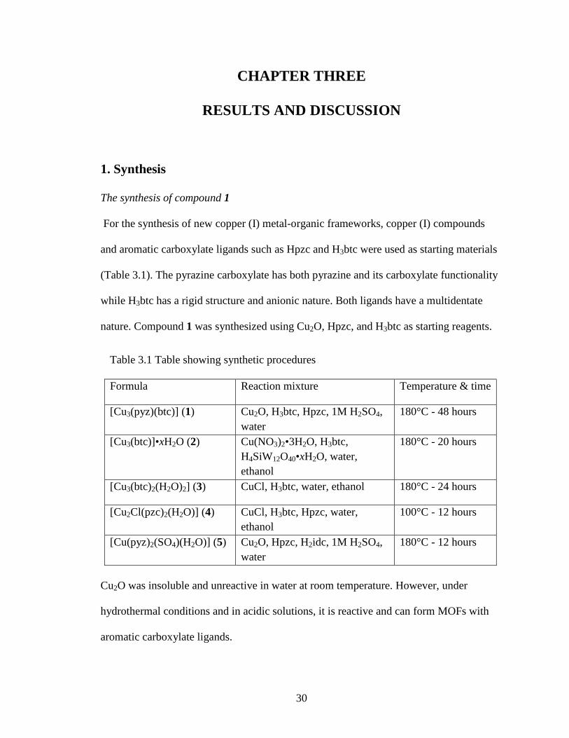
Figure 3.5 View of pores along ab plane
Channels are formed along the (1,0,1) direction and the pores are found to be elliptical
in shape (Figure 3.5). The pore is formed due to interconnection of different chains. The
pore diameter was calculated to be13.9Å.
Copper based frameworks containing mixed ligands were earlier reported.
[Cu2(OH)(2,2'-bipy)2(btc)32H2O]n ,4 [Cu3(3-bpcb)(1,2-bdc)2-µ2-OH)2] and [Cu
-2(3-bpcb)(1.5)(SIP)µ3 OH)]5 ([3-bpcb = N,N′= pc(3-pyridinecarboxamide)-1,4-benzene],
(1,2-H2bdc = 1,2-benzenedicarboxylic acid), (NaH2SIP= sodium 5-sulfoisophthalic acid))
were reported to contain mixed ligand groups. Other Cu(I) frameworks containing
pyrazine ligand are reported such as {Cu(pyz)1.5(ClO4)}n, {Cu(pyz)(NO3)}n,6
[Cu3Cl2CNPz].7 All the frameworks reported are 3D frameworks and have no structural
resemblance with Compound 1. Compound 1 is new and has not been reported yet.

40
Structure Description of Compound [Cu3(btc)]•xH2O (2)
Compound 2 crystallizes in the Iba2 space group and structural determination shows a
three-dimensional framework of Cu(I) bridged by btc ligands and water molecules. There
are crystallographically three types of copper having different coordination geometries
(Figure 3.6). Cu(1), Cu(2), Cu(5), Cu(6), Cu(7), Cu(8), Cu(9), Cu(11), Cu(12) exhibit
trigonal geometry and are coordinated to three oxygen atoms.
Figure 3.6 Coordination environments of different Cu ions within the framework.
Cu(5), Cu(9), Cu(11) coordinate to water molecule with bond distance of Cu--O(w) of
2.260Å, 2.228Å, 2.100Å for Cu(5)-O(13), Cu(9)-O(27) and Cu(11)-O(26) respectively
(Figure 3.7). Cu(3) and Cu(10) exhibit linear geometry and are coordinated to two
oxygen atoms of btc with bond distances in a range of 1.868 to 1.884Å. Cu(4) is
coordinated to three oxygen atoms with bond distances ranging from 1.899 to 2.376Å.

41
Figure 3.7 Bond lengths for various Cu-O bonds.
Within the framework, Cu(I) ions are present and these ions are bonded to other Cu(I)
ions having a bond length range of 2.415 to 2.528Å. Initially Cu(II) compound was used
for synthesizing the framework but within the reaction mixture, the cupric ions got
reduced to cuprous ions. The bond length of the Cu(I)-Cu(I) in the range 2.525 to 2.542Å
which is smaller than the bond distances for cupric ions in HKUST-1(2.682Å).
Figure 3.8 View of the porous framework along c-axis

42
A single layer of the framework consists of multiple {Cu3(btc)} chains repeating
throughout the framework similar to compound 1. Each btc ligand binds with six copper
ions through its carboxylate oxygen atoms forming a pseudo hexagonal ring and the
copper ions form a dimer (Figure 3.8). The structure contains pores formed from the
single layer. This single layer of framework (Figure 3.8) connects to other layers through
Cu-O bonds (2.587Å) and the bond angle formed in between two single layers ranges
from 79.067° - 106.979° (O(9)-Cu(1)-O(2)= 79.067°, O(26)-Cu(11)-O(19)= 97.334°,
O(4)-Cu(4)-O(2)= 106.979°).
Figure 3.9 Three dimensional view of the framework showing the 3D porous net(red)
interconnected with the 2D hexaogonal net(blue).
The crystal structure of this compound consists of two types of metal organic nets: a
two dimensional hexagonal net (blue in the figure, 2D net) and a three dimensional
porous framework (red in the figure, 3D net). There are two sets of parallel 2D nets
running at different orientations penetrating to each other. The dihedral angle is 79.0°.

43
The 2D net and the 3D net are connected by weak Cu-O bonds (2.587Å). The pores are
formed within the 3D net where the O-Cu-O atoms are present at an angle of 76.10°
indicating the formation of a circular pore from the adjacent layers. The circular pore
(along C-axis) is formed from four different layers each consisting of Cu-dimer. The pore
diameter is 6.615Å. The circular pores are present throughout the framework (Figure
3.9).
Unlike other frameworks containing copper and btc ligands such as HKUST-12, 2 has
Cu(I) ions bonding in Cu-dimers within the framework forming only circular pores
throughout structure. To the best of our knowledge, no compound with this framework
has been reported.
Structure Description of Compound [Cu3(btc)2(H2O)3] (3)
Compound 3 is a three dimensional framework built by Cu(II)ions and btc ligands.
This compound is known as HUKST-12 and has been studied extensively. The structure
contains chains of repeated [Cu2(RCO2)4] building units(Figure 3.10). The copper ion in
3 has a square pyramidal geometry and is five coordinated to five oxygen atoms. Four
oxygen atoms belong to the carboxyl ligand and the remaining oxygen belongs to a water
molecule. The bond distance for Cu-O is 1.940Å and for Cu-O(w) is 2.243Å. Within the
chain, two Cu(II) cations are bridged by four carboxylate groups to form a [Cu2(RCO2)4]
paddle wheel configuration with four carboxylate groups distributed around Cu-Cu axis
thus defining a square planar 4-connected mode (Figure 3.11). The ligands are also
square planar 4-connected nodes since all the four carboxylate groups lie in the same

44
plane. The btc ligands are bonded to Cu ions in a dimonodentate fashion thereby allowing
the Cu ion to extend the framework.
Figure 3.10 Structure of Cu2(RCO2)4 unit within the framework
Figure 3.11 Packing of the framework with copper tertacarboxylate groups along c-axis

45
Figure 3.12 Compound 3 viewed along the cell body
The 3D framework of 3 contains channels of ~10 Å. The pore opening of the channels
is measured to be ~ 9.5×13.3 Å. The octahedral unit consisting of Cu dimers with four
trimesate ions forms the secondary building units. The cell body diagonal [111] reveals
an arrangement of large psuedo-hexagonal shaped windows (Figure 3.12), each
composed of a ring of six metal dimers and six trimesate groups, which measure 18.632Å
between opposite vertices. The pore diameter of the framework was found to be 11.292Å.
Structure Description of Compound [Cu2Cl(pzc)2(H2O)]n (4)
Compound [Cu2Cl(pzc)2(H2O)]n (4) exhibited three dimensional structure built up
from mixed valence chains of CuICuII(pzc)2(H2O) linked by halide ions. Figure 3.13
shows a fragment of the layer in compound 4. Three kinds of copper are
crystallographically distinguishable due to their coordination geometry. The Cu(1) ion
exhibits octahedral coordination geometry, Cu(2) ion exhibits tetrahedral geometry and
Cu(3) exhibits square planar geometry. Cu(1) is a divalent ion and is six coordinated by

46
two carboxyl oxygen atoms, two nitrogen atoms of pzc, and two oxygen atoms. Cu(2)
and Cu(3) are monovalent ions. Cu(2) is bonded to two nitrogen atoms of pzc, one
oxygen atom and one halide ion. Cu(3) is four coordinated to two carboxyl oxygen atoms
and two nitrogen of pzc.
Figure 3.13 Layer formations in compound 4 with atomic labeling
The Cu(1)-O(4)[1.957Å] and Cu(1)-N[ 2.004, 2.002Å] are in agreement with those of
Cu(pzc)2 [Cu-O=1.93Å, Cu-N=1.98Å]. The Cu(1)-O(1w) have a bond length of 2.471Å
and Cu(2)-O(1w) have a bond length of 2.354Å. The Cu(1)-(pzc) units are linked by
cuprous ions Cu(2) through bonding through nitrogen atoms of the pzc molecule forming
infinite chains(Figure 3.14). The [Cu2N2Cl2] tetrahedral are bonded to Cu(1) through Cl
and N atoms. Cu(2) is bonded to Cu(3) through nitrogen atoms of pzc. The pzc moiety
uses its nitrogen atoms and carboxyl oxygen for elongating the chain by bonding to
different copper ions. The remaining oxygen atom of pzc is uncoordinated and
considered as water molecule. Weak hydrogen bonds are found within the layer and

47
between the layers. The oxygen (O1w) atom present within the framework helps in
linking different chains to form an two dimensional layer (Figure 3.15). Along ab plane
rectangular pores are visible having a pore diameter of 10.851Å
This structure was already reported by Zheng et.al. group.8 Their method of synthesis
was different but the framework dimensions and arrangement of ions were similar to our
compound.
Figure 3.14 Packing diagram of the structure of 4 along a-axis

48
Figure 3.15 Chain formations of compound 4 along c-axis
Structure Description of Compound [Cu2(pyz)2(SO4)(H2O)2] (5)
This structure was already reported by Ochua et.al. using microwave assisted synthetic
procedure.9 Single crystal x-ray diffraction studies of compound 5 indicated the presence
of Cu(I) ions within the framework. Compound 5 exhibits three dimensional structure
consisting of Cu(I) ions connected by pyrazine and sulfate sulfate ligands (Figure 3.16).
The copper ion exhibits distorted tetrahedral coordination geometry. The pyrazine ligands
link the Cu ions to form chains in two directions. Those chains are bridged by SO42- to
form a three dimensional framework. The sulfate ligand coordinates with Cu(I) through
an oxygen atom and it connects another Cu(I) ion through one more oxygen. The
remaining two oxygen atoms of sulfate are uncoordinated. The water molecule (O3)
binds to one copper ion and forms two short hydrogen bonds to form a water molecule.
The bond lengths for Cu--O ranges from 2.105 to 2.201Å and the bond lengths for Cu--N
ranges from 1.958 to 1.991Å. The bond angles between the pyrazines molecules and Cu

49
ions is125.489°. Distorted hexagonal pores of the framework are formed. The pore
diameter is formed throughout different chains and it has a diameter of 19.807Å (Figure
3.17).
Figure 3.16 View of the coordination center of Cu with atomic labeling.
Figure 3.17 View of the pores along ab plane

50
Thermogravimetric Analysis
Thermogravimetric analysis was performed to study the thermal stability of the
compound-1.
Figure 3.18 Thermogravimetric analysis of compound 1.
The crystalline samples of compound were heated from 30° to 800° C in the presence
of Nitrogen gas at a heating rate of 10° C/min. The nitrogen was allowed to flow at rate
of 40ml/min. An initial weight loss of 8% was observed when the temperature increased
from 30°C - 300°C. As the temperature increased to 420°C, the weight loss was recorded
to be 30%. It could be attributed to the decomposition of btc and pyz ligands.
40
50
60
70
80
90
100
110
0 100 200 300 400 500 600 700 800 900
Wei
ght
loss
(%)
Temperature (°C)

51
Infrared Spectroscopy
Figure 3.19 Infrared spectra for compound 1
The bands around 1602 cm-1 to 1539 cm-1 can be assigned to aromatic rings present in
the compound. The C=O stretching at 1069 cm-1 is due to presence of carboxylic acid
functional groups in the ligands.The bands observed between 700 cm-1 to 1200 cm-1 can
be assigned to C-H and C-C bending of the benzene ring.
30
40
50
60
70
80
90
600 1200 1800 2400 3000 3600
% T
wavelength cm(-1)
52
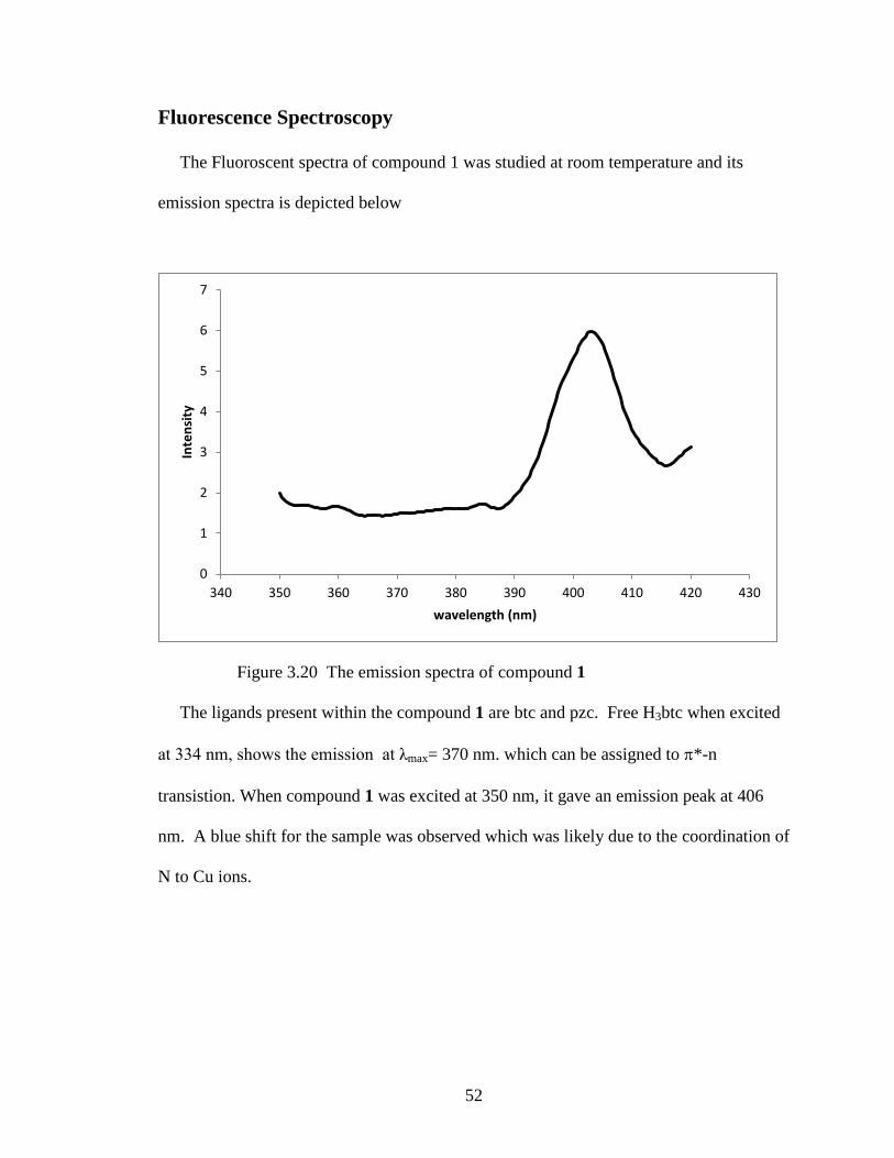
Fluorescence Spectroscopy
The Fluoroscent spectra of compound 1 was studied at room temperature and its
emission spectra is depicted below
Figure 3.20 The emission spectra of compound 1
The ligands present within the compound 1 are btc and pzc. Free H3btc when excited
at 334 nm, shows the emission at λmax= 370 nm. which can be assigned to π*-n
transistion. When compound 1 was excited at 350 nm, it gave an emission peak at 406
nm. A blue shift for the sample was observed which was likely due to the coordination of
N to Cu ions.
0
1
2
3
4
5
6
7
340 350 360 370 380 390 400 410 420 430
Inte
nsit
y
wavelength (nm)

53
REFERENCES 1. Zhang, X. M. Coord. Chem. Rev. 2005, 249, 1201.
2. Chui, S. S. Y.; Lo, S. M. F.; Charmant, J. P. H.; Orpen, A. G.; Williams, I. D. Science.
1999, 283, 1148.
3. Che, C-M.; Mao, Z.; Miskowski, V. M.; Chan, C-K.; Cheung, K-K.; Philips, D. L.;
Leung, K-H. Angew. Chem. Int. Ed. 2000, 39, 4084.
4. Song, L-F.; Jiang, C-H.; Jiuo, C-L.; Zhang, T.; Sun, L-X.; Xu, F.; You, W-S.; Wang,
Z-G.; Zhao, J. Cryst. Growth Des. 2010, 10, 5020.
5. Wang, X-L.; Mu, B.; Lin, H-Y.; Yang, S.; Liu, G-C. J. Mol. Str. 2013, 1036, 380.
6. Mohapatra, S.; Maji, T. K.; Dalton Trans. 2010, 39, 3412.
7. Persky, N. S.; Chow, J. S.; Poschmann, K. A.; Lacuesta, N. N.; Stoll, S. L.; Inorg.
Chem. 2001, 40, 29.
8. Zheng, L. M.; Wang, X. Q.; Jacobson, A. J. J. Solid State Chem. 2000, 152, 174.
9. Ochao, P. A.; Givija, G.; Miguel, P. J. S.; Castillo, O.; Zomaro, F. Inorg. Chem.
Commun. 2007, 10, 921.

54
CHAPTER FOUR
CONCLUSIONS
Two new copper metal-organic frameworks have been synthesized using
hydro/solvothermal methods: [Cu3(pyz)(btc)] and [(Cu3(btc)) •xH2O]. The structure of
compound [Cu3(pyz)(btc)] is a 3D framework consisting of copper connected by pyz and
btc ligands. This compound is characterized by single crystal X-ray diffraction,
elemental analysis, thermo gravimetric analysis, fluorescent studies and infrared
spectroscopy. Compound 2 is a 3D porous framework in which the copper ions and btc
ligands are connected in a C-shaped ring forming a pore within the framework.
Three copper metal-organic frameworks were also synthesized whose structure have
already been reported by other research groups. The compounds were synthesized in
hydro/solvothermal methods: [Cu3(btc)2(H2O)3], [Cu2Cl(pzc)2(H2O)] ,
[Cu(pyz)2(SO4)(H2O)2]. [Cu3(btc)3(H2O)3] has a unique structure of copper ions
surrounded by four btc ligands. The framework is 3D and porous in nature.
[Cu2Cl(pzc)2(H2O)] is a 2D framework built up from mixed valence chains of
CuICuII(pzc)2(H2O) linked by chloride ions. [Cu(pyz)2(SO4)(H2O)] is a 3D porous
framework with sulfate ions acting as bridging ions of chains formed by Cu ions and pyz
ligands.

55
APPENDIX
Table 1. Reaction sets for Compound 1
S.No Reactants Ratio Temperature/time
Solvent used
Special conditions
1. Cu2O - H3btc - Hpzc
1:1:1 2:1:1 3:1:1
180°C/ 12hrs Water and 1M H2SO4
Nitrogen gas
2. Cu2O - H3btc - Hpzc
1:1:1 2:1:1 3:1:1
180°C/ 24hrs Water and 1M H2SO4
Nitrogen gas
3. Cu2O - H3btc -Hpzc
1:1:1 2:1:1 3:1:1
180°C/ 48hrs Water Nitrogen gas, 1M H2SO4- 0.5mL, 1mL, 1.5mL
4. Cu2O - H3btc
2:1 180°C/ 12hrs Water and Ethanol
Nitrogen gas, 1M H2SO4- 0.4 mL, 0.5 mL, 0.6 mL
5. Cu2O - H3btc
2:1 180°C/ 12hrs Water Nitrogen gas, 1M NaOH-0.2mL, 0.3mL, 0.4mL
6. Cu2O - H3btc
2:1 180°C/ 12hrs Water and Ethanol
Nitrogen gas, 1M HCl- 0.2mL, 0.3mL, 0.4mL, 0.5mL
7. Cu2O - H3btc
2:1 180°C/ 12hrs Water Nitrogen gas, 1M HCl- 0.2mL, 0.3mL, 0.4mL
8. Cu2O - H3btc
1:1 180°C/ 12hrs Water Nitrogen gas, 1M NaOH-0.6mL, 1M HCl- 0.6mL
9. Cu2O - H3btc
1:1 2:1 3:1
200°C/ 12hrs Water Nitrogen gas

56
Table 2. Reaction sets for Compound 2.
S.No Reactants Ratio Temperature Solvents Special conditions
1. Cu(NO3)2.3H2O - H3btc - Tungstosilicic acid
1:1:1 2:1:1 3:1:1
30- 200°C- 6 hours 200°C- 20 hours 200- 100°C - 6 hours
Water and Ethanol
Slow heating and slow cooling
2. Cu(NO3)2.3H2O - H3btc - Tungstosilicic acid
1:1:1 2:1:1 3:1:1
30- 200°C- 6 hours 200°C- 20 hours 200- 100°C - 6 hours
Water and Ethanol
Weights of Copper nitrate and BTC were changed
3. Cu(NO3)2.3H2O - H3btc- Tungstosilicic acid
1:1:1 2:1:1
30- 180°C - 6 hours 180°C - 20 hours 180- 100°C - 6 hours
Water and Ethanol
Decrease of temperature
4. Cu(NO3)2.3H2O - H3btc - Tungstosilicic acid
1:1:1 2:1:1
30- 180°C - 6 hours 180°C- 20 hours 180- 100°C - 6 hours
Water and Ethanol
Change in pH

57
Table 3. Reaction sets for Compound 3
S.No Reactants Ratio Temperature Solvents Special conditions 1. CuCl-
H3btc 1:1 1:2 1:0.5
180°C/ 12 hours Water Nitrogen Gas
2. CuCl- H3btc
1:1 1:2 1:0.5
180°C/ 12 hours Water and ethanol
Nitrogen gas
180°C / 48 hour
3. CuCl- H3btc
1:1 180°C/ 12 hours Water and ethanol
Nitrogen gas 1M NaOH= 0.7 mL, 0.5mL, 0.8mL
4. CuCl- H2bdc
1:1 180°C/ 12 hours Water and ethanol
Nitrogen gas 1M NaOH= 0.2 mL, 0.3mL, 0.4 mL
5. CuCl- H3btc
1:1 1:2 1:0.5
80°C/ 12 hours DMF Nitrogen Gas
6. CuCl- H3btc
1:1 1:2 1:0.5
80°C/ 12 hours DMF and water
Nitrogen Gas
7. CuCl- H3btc
1:1 1:2 1:0.5
80°C/ 12 hours Acetonitrile Nitrogen Gas
8. CuCl- H3btc
1:1 2:1 3:1
80°C/ 12 hours DMF Nitrogen Gas 1M NaOH
9. CuCl- H3btc
1:1 2:1 3:1
180°C/ 12 hours DMF and water
Nitrogen Gas 1M NaOH
10. CuCl- H3btc
1:1 2:1 3:1
80°C/ 12 hours Acetonitrile Nitrogen Gas 1M NaOH
11. CuCl- H3btc
1:1 180°C/ 12 hours Water Nitrogen Gas 1M HCl
12. CuCl- H3btc
1:1 180°C/ 12 hours Water and ethanol
Nitrogen Gas 1M HCl
13. CuCl- H3btc
1:1 180°C/ 12 hours Water and methanol
Nitrogen Gas 1M HCl

58
Table 4. Reaction sets for Compound 4
S.No Reactants Ratio Temperature Solvent Special Conditions
1. CuCl- Hpzc 1:1 2:1 3:1
180°C/ 12 hours Water Nitrogen Gas
2. CuCl- Hpzc 1:1 2:1 3:1
180°C/ 12 hours 1M HCl Nitrogen Gas
3. CuCl- Hpzc 1:1 2:1 3:1
180°C/ 12 hours 1M NaOH Nitrogen Gas
4. CuCl- Hpzc 1:1 180°C/ 24 hours 1M HCl and water
Nitrogen Gas
5. CuCl- Hpzc - H3btc
1:1:1 2:1:1 3:1:1
180°C/ 12 hours Water Nitrogen Gas
6. CuCl- Hpzc - H3btc
1:1:1 2:1:1 3:1:1
180°C/ 12 hours Water and Ethanol
Nitrogen Gas
7. CuCl- Hpzc - H2bdc
1:1:1 2:1:1 3:1:1
120°C/ 12 hours Water Nitrogen Gas
8. CuCl- Hpzc - H2bdc
1:1:1 2:1:1 3:1:1
120°C/ 12 hours Water and Ethanol
Nitrogen Gas
9. CuCl- Hpzc- H3btc
1:1:1 2:1:1 3:1:1
80°C/ 12 hours Acetonitrile Nitrogen Gas

59
Table 5. Reaction sets for Compound 5
S.No Reactants Ratio Temperature Solvents Special conditions
1. CuCl- H3btc - H2idc
1:1:1 2:1:1 3:1:1
180°C/ 12 hours Water Nitrogen Gas
2. CuCl- PZC- H2idc
4:1:1 5:1:1 6:1:1
180°C/ 12 hours Water Nitrogen Gas 180°C/ 48 hours
3. Cu2O- Hpzc-H2bdc
1:1:1 30- 180°C- 12 hours 180°C- 12 hours 180- 30°C - 12 hours
Water Nitrogen Gas 1M H2SO4 - 1mL, 1.5mL, 2mL
4. Cu2O- Hpzc- H2idc
1:1:1 30- 180°C- 12 hours 180°C- 12 hours 180- 30°C - 12 hours
Water Nitrogen Gas 1M H2SO4 - 1mL, 1.5mL, 2mL
5. Cu2O- Pyrazine 1:1 30- 180°C- 12 hours 180°C- 12 hours 180- 30°C - 12 hours
Water Nitrogen Gas 1M H2SO4 - 1mL, 1.5mL, 2mL

60
Table 6. Selected bond lengths [Å] for compounds 1 and 2
Compound 1 Compound 2 Cu(1)-O(7) 1.937(1) Cu(1)-O(2) 1.908(1) Cu(1)-O(5) 1.957(1) Cu(1)-O(12) 1.891(1) Cu(1)-N(2) 2.096(1) Cu(2)-O(1) 1.894(1) Cu(2)-O(2) 1.938(1) Cu(2)-O(11) 1.900(1) Cu(2)-O(3) 1.948(1) Cu(3)-O(8) 1.861(2) Cu(2)-N(1) 2.096(1) Cu(4)-O(4) 1.895(1) Cu(3)-O(1) 1.898(2) Cu(4)-O(9) 1.899(1) Cu(6)-O(3) 1.905(1) Cu(7)-O(24) 1.869(1)

61
Table 7. Crystal data and structure refinement for Compound 1.
Identification code Compound 1 Empirical formula C13H7Cu3N2O6 Formula weight 477.86 Temperature 573(2) K Wavelength 0.71073 Å Crystal system Monoclinic Space group C2/c Unit cell dimensions a = 12.0050(4) Å α= 90°. b = 15.8263(5) Å β= 90.831(2)°. c = 14.5219(6) Å γ = 90°. Volume 2758.79(17) Å3 Z 8 Density (calculated) 2.301 Mg/m3 Absorption coefficient 4.619 mm-1 F(000) 2312 Crystal size 0.32 x 0.30 x 0.25 mm3 Theta range for data collection 2.13 to 39.08°. Index ranges -18<=h<=20, -25<=k<=25, -20<=l<=22 Reflections collected 17900 Independent reflections 6125 [R(int) = 0.0477] Completeness to theta = 39.08° 75.9 % Max. and min. transmission 0.3628 and 0.2929 Refinement method Full-matrix least-squares on F2 Data / restraints / parameters 6125 / 0 / 217 Goodness-of-fit on F2 1.024 Final R indices [I>2sigma (I)] R1 = 0.0308, wR2 = 0.0812 R indices (all data) R1 = 0.0426, wR2 = 0.0865 Largest diff. peak and hole 1.133 and -0.816 e.Å-3

62
Table 8. Crystal data and structure refinement for Compound 2.
Identification code Compound 2 Empirical formula C288H96Cu96O259 Formula weight 144.79 Temperature 296(2) K Wavelength 0.71073 Å Crystal system Orthorhombic Space group Iba2 Unit cell dimensions a = 20.1936(3) Å α= 90°. b = 24.5767(3) Å β= 90°. c = 18.6324(2) Å γ= 90°. Volume 9247.1(2) Å3 Z 1 Density (calculated) 2.462 Mg/m3 Absorption coefficient 5.505 mm-1 F(000) 8132 Theta range for data collection 2.02 to 29.28°. Index ranges -27<=h<=27, -33<=k<=33, -25<=l<=25 Reflections collected 108643 Independent reflections 12603 [R (int) = 0.0380] Completeness to theta = 29.28° 99.8 % Refinement method Full-matrix least-squares on F2 Data / restraints / parameters 12603 / 1 / 670 Goodness-of-fit on F2 1.355 Final R indices [I>2sigma(I)] R1 = 0.0506, wR2 = 0.1649 R indices (all data) R1 = 0.0594, wR2 = 0.1716 Absolute structure parameter 0.900(16) Largest diff. peak and hole 2.283 and -1.243 e.Å-3

63
Table 9. Crystal data and structure refinement for Compound 3.
Identification code Compound 3 Empirical formula C18H12Cu3O15 Formula weight 658.90 Temperature 293(2) K Wavelength 0.71073 Å Crystal system Cubic Space group Fm3m Unit cell dimensions a = 26.2569(4) Å α= 90°. b = 26.2569(4) Å β= 90°. c = 26.2569(4) Å γ= 90°. Volume 18102.2(5) Å3 Z 32 Density (calculated) 0.96 Mg/m3 Absorption coefficient 2.871 mm-1 F(000) 10464 Crystal size 0.09 x 0.07 x 0.06 mm3 Theta range for data collection 1.34 to 21.17°. Index ranges -26<=h<=26, -26<=k<=26, -26<=l<=26 Reflections collected 54776 Independent reflections 561 [R(int) = 0.2779] Completeness to theta = 21.17° 100.0 % Refinement method Full-matrix least-squares on F2 Data / restraints / parameters 561 / 0 / 36 Goodness-of-fit on F2 1.273 Final R indices [I>2sigma(I)] R1 = 0.1421, wR2 = 0.3601 R indices (all data) R1 = 0.1468, wR2 = 0.3622 Largest diff. peak and hole 1.370 and -1.099 e.Å-3

64
Table 10. Crystal data and structure refinement for Compound 4.
Identification code Compound 4 Empirical formula C10H2ClCu2N4O5 Formula weight 420.69 Temperature 573(2) K Wavelength 0.71073 Å Crystal system Triclinic Space group P-1 Unit cell dimensions a = 6.19150(10) Å α= 78.4100(10)°. b = 7.72780(10) Å β= 81.3960(10)°. c = 14.0188(2) Å γ= 77.9420(10)°. Volume 638.511(16) Å3 Z 2 Density (calculated) 2.188 Mg/m3 Absorption coefficient 3.569 mm-1 F(000) 410 Crystal size 0.30 x 0.25 x 0.20 mm3 Theta range for data collection 1.49 to 39.03°. Index ranges -10<=h<=10, -13<=k<=13, -24<=l<=24 Reflections collected 23087 Independent reflections 6897 [R(int) = 0.0282] Completeness to theta = 39.03° 92.6 % Absorption correction None Max. and min. transmission 0.5354 and 0.4140 Refinement method Full-matrix least-squares on F2 Data / restraints / parameters 6897 / 0 / 202 Goodness-of-fit on F2 0.768 Final R indices [I>2sigma(I)] R1 = 0.0289, wR2 = 0.0802 R indices (all data) R1 = 0.0331, wR2 = 0.0833 Largest diff. peak and hole 0.912 and -1.304 e.Å-3
