synthesis of energy-bounded planar caging grasps...
TRANSCRIPT
Synthesis of Energy-Bounded Planar CagingGrasps using Persistent Homology
Jeffrey Mahler1,∗, Florian T. Pokorny1,2,∗, Sherdil Niyaz1, Ken Goldberg1
1AUTOLAB and Berkeley Artificial Intelligence Research LaboratoryDept. of IEOR and EECS, University of California, Berkeley, USA
{jmahler, sniyaz, goldberg}@berkeley.edu2 CAS/CVAP, KTH Royal Institute of Technology, Sweden
[email protected]∗ These authors contributed equally
Abstract. Caging grasps restrict object motion without requiring com-plete immobilization, providing a robust alternative to force- and form-closure grasps. Energy-bounded cages are a new class of caging graspsthat relax the requirement of complete caging in the presence of ex-ternal forces such as gravity. In this paper, we address the problem ofsynthesizing energy-bounded cages by identifying optimal gripper andforce-direction configurations that require the largest increases in poten-tial energy for the object to escape. We present Energy-Bounded-Cage-Synthesis-2D (EBCS-2D), a sampling-based algorithm that uses persis-tent homology, a recently-developed multiscale approach for topologicalanalysis, to efficiently compute candidate rigid configurations of obstaclesthat form energy-bounded cages of an object from an α-shape approxi-mation to the configuration space. We also show that constant velocitypushing in the horizontal plane generates an energy field analogous togravity in the vertical plane that can be analyzed with our algorithm.EBCS-2D runs in O(s3 + sn2) time where s is the number of samplesand n is the total number of object and obstacle vertices, where typicallyn << s. We observe runtimes closer to O(s) for fixed n. We implementEBCS-2D using the Persistent Homology Algorithms Toolbox (PHAT)and study performance on a set of seven planar objects and four grippertypes. Experiments suggest that EBCS-2D takes 2-3 minutes on a 6 coreprocessor with 200,000 pose samples. We also confirm that an RRT* mo-tion planner is unable to find escape paths with lower energy. Physicalexperiments suggest that push grasps synthesized by EBCS-2D are ro-bust to perturbations. Additional proofs, data, and code are available athttp://berkeleyautomation.github.io/caging/.
1 Introduction
In manufacturing and logistics, there are many applications where parts mustbe reliably grasped and moved without precise constaints on object pose (asrequired for example in assembly). Caging configurations, in which an object’smobility is bounded by a set of obstacles such as a gripper and / or an energy
field such as gravity, are a promising alternative to form- and force-closure asthey provide robustness to perturbations in object pose.
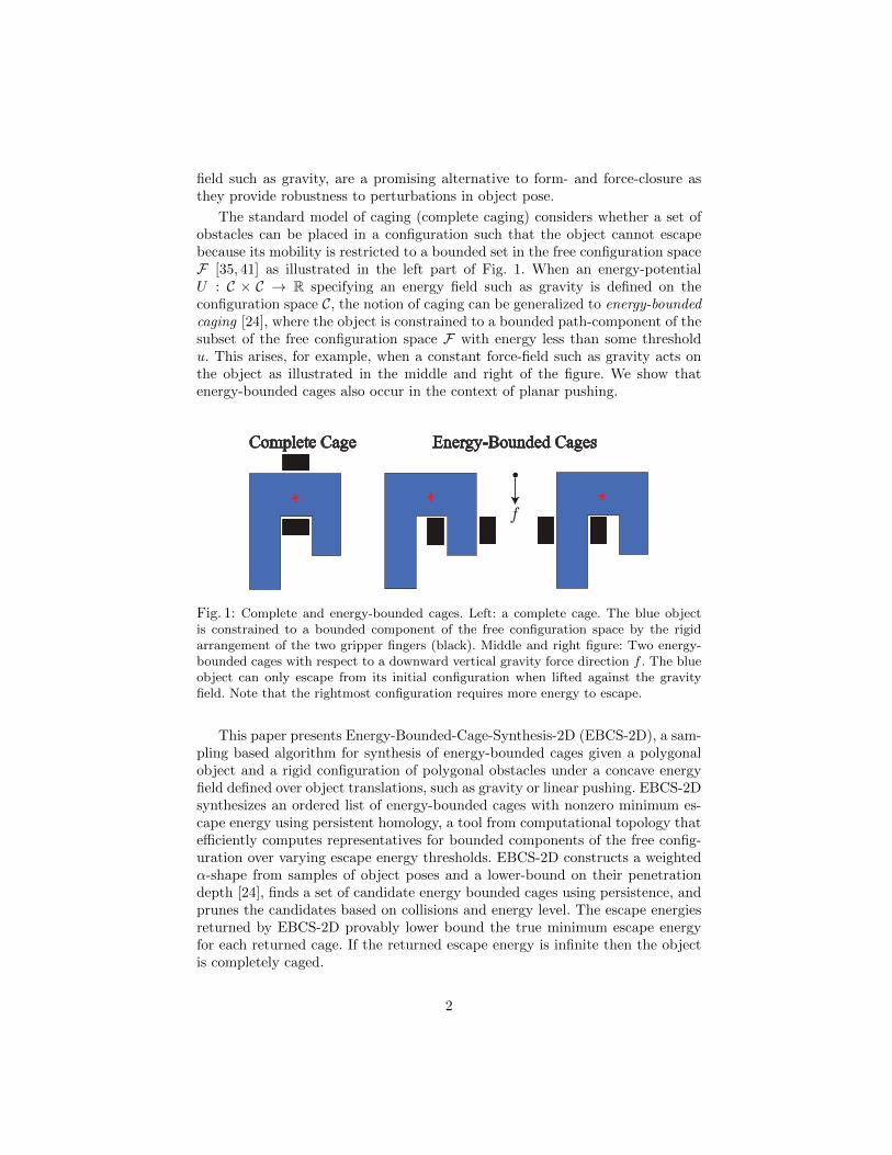
The standard model of caging (complete caging) considers whether a set ofobstacles can be placed in a configuration such that the object cannot escapebecause its mobility is restricted to a bounded set in the free configuration spaceF [35, 41] as illustrated in the left part of Fig. 1. When an energy-potentialU : C × C → R specifying an energy field such as gravity is defined on theconfiguration space C, the notion of caging can be generalized to energy-boundedcaging [24], where the object is constrained to a bounded path-component of thesubset of the free configuration space F with energy less than some thresholdu. This arises, for example, when a constant force-field such as gravity acts onthe object as illustrated in the middle and right of the figure. We show thatenergy-bounded cages also occur in the context of planar pushing.
Complete Cage Energy-Bounded Cages
Fig. 1: Complete and energy-bounded cages. Left: a complete cage. The blue objectis constrained to a bounded component of the free configuration space by the rigidarrangement of the two gripper fingers (black). Middle and right figure: Two energy-bounded cages with respect to a downward vertical gravity force direction f . The blueobject can only escape from its initial configuration when lifted against the gravityfield. Note that the rightmost configuration requires more energy to escape.
This paper presents Energy-Bounded-Cage-Synthesis-2D (EBCS-2D), a sam-pling based algorithm for synthesis of energy-bounded cages given a polygonalobject and a rigid configuration of polygonal obstacles under a concave energyfield defined over object translations, such as gravity or linear pushing. EBCS-2Dsynthesizes an ordered list of energy-bounded cages with nonzero minimum es-cape energy using persistent homology, a tool from computational topology thatefficiently computes representatives for bounded components of the free config-uration over varying escape energy thresholds. EBCS-2D constructs a weightedα-shape from samples of object poses and a lower-bound on their penetrationdepth [24], finds a set of candidate energy bounded cages using persistence, andprunes the candidates based on collisions and energy level. The escape energiesreturned by EBCS-2D provably lower bound the true minimum escape energyfor each returned cage. If the returned escape energy is infinite then the objectis completely caged.
2
We implement EBCS-2D using the Persistent Homology Algorithms Toolbox(PHAT) [3] to efficiently identify the most robust energy bounded cages. Weevaluate EBCS-2D on a set of seven polygonal parts with parallel-jaw grippersusing a push energy field and use it to synthesize optimal push directions. Ineach case, RRT* optimal path planning was unable to find an escape path withlower energy than the estimated lower bound within 120 seconds. We also applyEBCS-2D to the problem of planar pushing on a Zymark Zymate robot andfind that configurations synthesized by EBCS-2D successfully push objects on aplanar worksurface.
2 Related WorkComplete caging vs energy-bounded caging: The standard concept of caging,
which we refer to as “complete” caging, was introduced by Kuperberg [19] in1990 and extended by Rimon and Blake [34]. Caging is distinct from completeimmobilization of an object by means of form or force closure grasps [29]. Unlikeapproaches that depend on the local contact geometry, a complete cage of anobject causes the object to be constrained to a bounded subset of its free config-uration space and requires reasoning about global properties of the configurationspace.
Early research on caging studied the caging condition for n points in the planecaging a planar object [19, 35]. Rimon and Blake [34] described the space of cagesfor a two-finger gripper with one degree of freedom. Sudsang and Ponce [38, 39]proposed caging-based methods for manipulating polygonal objects by means ofdisc-shaped robots in the plane. Recently, Allen, Burdick and Rimon [2] proposedan algorithm to find all two-finger cage formations of planar polygonal objectsby two point-fingers. Vahedi and van der Stappen [41] studied the computationof two and three-finger cages on polygons and used a classification into squeezingand stretching cages. Rodriguez and Mason [36] established and studied caging asa pre-stage to force-closure grasping. Diankov et al. [9] demonstrated that caginggrasps can be used to manipulate articulated objects such as door handles.
Recent research has focused on computing cages for specific object familiesor approximate algorithms due to the difficulty of computing the configurationspace for complex gripper and object geometries. These lines of research haveprimarily focused on synthesizing caging grasps from features in the object sur-face [33, 20] (e.g. handles) using features of the object surface to rank potentialcaging configurations [25]. Other research has focused on cell-based approxi-mations of the configuration space based on sampling [42]. Mahler et al. [24]defined energy-bounded caging and presented EBCA-2D, an analysis algorithmthat can provably lower bound the minimum escape energy to verify energy-bounded cages for a fixed object and obstacle configuration. The present paperproposes a synthesis algorithm, Energy-Bounded-Cage-Synthesis-2D (EBCS-2D)and considers energy-bounded cages in the context of planar pushing.
Pushing for manipulation: Mason introduced the study of planar pushing torobotics [27] and studied mechanics and planning problems for pushing opera-tions [26]. Constant-velocity quasi-static planar pushing in the horizontal planecan be modeled by an energy potential. Peshkin and Sanderson [30] gave a
3
method to find the locus of the centers of rotation of a planar object for all pos-sible pressure distributions of the object on a planar worksurface. Planar pushingcan reduce grasp uncertainty using mechanical compliance and can be used toorient parts [1]. Goldberg [17] gave the first complete algorithm for synthesizinga sequence of pushes to orient polygonal parts without sensory feedback. Lynchand Mason investigated controllability of planar pushing, to determine whetheran object can be moved between two configurations purely by pushing actionsusing point and line contacts [23]. Dogar et al. [10] used a physics-based analy-sis of two-dimensional contact wrenches to compute push-grasps in clutter andproposed a combinatorial search method to plan push-grasps in [11]. Koval etal. [18] decomposed grasping policies into a pre- and post-contact strategy toreduce uncertainty during pushing actions preceding a grasp using a POMDPplanner.
Representations and algorithmic approach: We utilize sampling and a discreterepresentation of the collision space using α-shapes to reason about cages, build-ing on previous work on motion planning and computational topology. Semi-algebraic functions can be used to prove path non-existence [22], but in practicecan be prohibitively expensive to compute. Zhang et al. [44] utilized a rectangu-lar cell-decomposition of the configuration space to prove path non-existence formotion planning by assigning cells to the collision space based on penetrationdepth. McCarthy et al. [28] use (weighted) α-shapes, a simplicial complex con-struction defined by Edelsbrunner [13], to represent the collision space from posesamples, and present an algorithm that can prove path non-existence. We buildon our previous work [24], which showed that an α-shape-based approximationto the configuration space could be used to analyze a given object and obstacleconfiguration to check it it is a complete or energy-bounded cage. The presentpaper also builds on recent advances in topological data analysis [7] and the con-cept of persistent homology [12] to identify “voids” corresponding to cages. Otherapplications of persistent homology in robotics include methods for clusteringtrajectories [31] and for motion planning [32, 4].
3 Definitions and Problem Statement
Given a rigid polygonal object O, a rigid configuration of obstacles G ona planar worksurface, and a potential function P , we consider the problem offinding the set of energy-bounded cages of O by G with nonzero minimum escapeenergy.
Complete Caging and Energy-Bounded Caging
We consider a planar configuration space C ⊆ SE(2) of a compact polygonalplanar object O ⊂ R2 placed in a planar workspace with obstacles defined byfixed positions of a set of k polygons G = P1∪. . .∪Pk ⊂ R2, such as the jaws of arobotic gripper. We assume the center of mass is known for both the object andobstacles. We denote the object polygon in pose q = (x, y, θ) ∈ SE(2) = R2×S1relative to a reference pose q0 by O(q). We define the collision space of O relative
4
to G by Z = {q ∈ SE(2) : int(O(q)) ∩ G 6= ∅} and denote by F = SE(2) − Zthe free configuration space.
We define the energy required to move the object between poses by an energyfunction U : SE(2) × SE(2) → R satisfying U(q,q) = 0,∀q ∈ SE(2). Thisis consistent with [24], in which the reference pose was implicit in the energyfunction. For a fixed threshold u ∈ R and reference q0 ∈ SE(2) define the u-energy forbidden space by Zu(q0) = Z∪{q ∈ C : U(q,q0) > u} and the u-energyadmissible space Fu(q0) = SE(2) − Zu(q0). In this work we use the followingdefinitions of caging as in [24] (see Fig. 2):
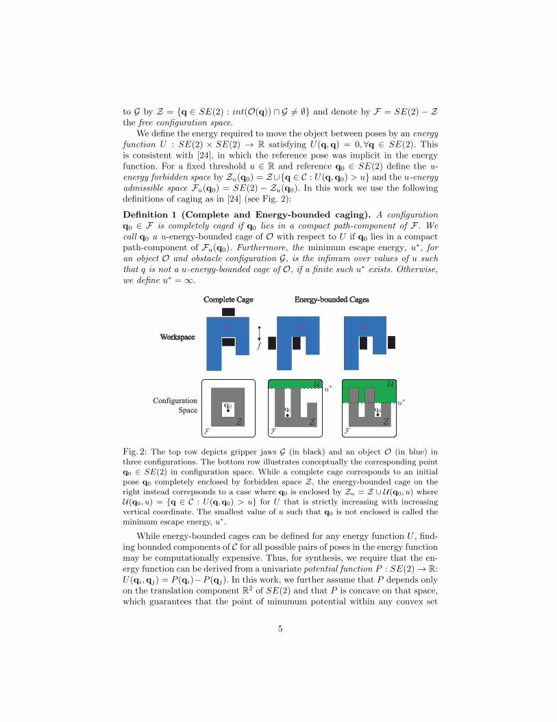
Definition 1 (Complete and Energy-bounded caging). A configurationq0 ∈ F is completely caged if q0 lies in a compact path-component of F . Wecall q0 a u-energy-bounded cage of O with respect to U if q0 lies in a compactpath-component of Fu(q0). Furthermore, the minimum escape energy, u∗, foran object O and obstacle configuration G, is the infimum over values of u suchthat q is not a u-energy-bounded cage of O, if a finite such u∗ exists. Otherwise,we define u∗ =∞.
u∗u∗
Complete Cage Energy-bounded Cages
Workspace
Configuration
Spaceq0 q0q0
UU
Fig. 2: The top row depicts gripper jaws G (in black) and an object O (in blue) inthree configurations. The bottom row illustrates conceptually the corresponding pointq0 ∈ SE(2) in configuration space. While a complete cage corresponds to an initialpose q0 completely enclosed by forbidden space Z, the energy-bounded cage on theright instead correpsonds to a case where q0 is enclosed by Zu = Z ∪ U(q0, u) whereU(q0, u) = {q ∈ C : U(q,q0) > u} for U that is strictly increasing with increasingvertical coordinate. The smallest value of u such that q0 is not enclosed is called theminimum escape energy, u∗.
While energy-bounded cages can be defined for any energy function U , find-ing bounded components of C for all possible pairs of poses in the energy functionmay be computationally expensive. Thus, for synthesis, we require that the en-ergy function can be derived from a univariate potential function P : SE(2)→ R:U(qi,qj) = P (qi)−P (qj). In this work, we further assume that P depends onlyon the translation component R2 of SE(2) and that P is concave on that space,which guarantees that the point of minumum potential within any convex set
5
is on the boundary of the set. Given such an energy field U , the objective is tosynthesize all energy-bounded cages qi ∈ SE(2) with nonzero minimum escapeenergy.
Energy Functions
We now derive energy functions for gravity in the vertical plane and constantforce pushing in the horizontal plane. We develop such functions based on theenergy (mechanical work) that wrenches must exert to transport the objectbetween two poses under a nominal wrench resulting from pushing or gravity.
Gravity in the Vertical Plane. Let m denote the mass of the object.Then the energy required to move the object from a reference configurationqi to configuration qj is U(qj ,qi) = mg(yj − yi), where g = 9.81m/s2 is theacceleration due to gravity in the y-direction [16, 24]. This corresponds to thepotential P (q) = mgy.
Constant-Velocity Linear Pushing in the Horizonal Plane. Consideran object being pushed along a fixed direction v by a gripper with a constantvelocity on a horizonal worksurface under quasi-static conditions and Coloumbfriction with uniform coefficient of friction µ [27, 26, 30]. Then the energy functionU(qj ,qi) = Fp(O,G, µ)v · (xj − xi, yj − yi) − κ(O,G, µ) is a lower bound onthe energy required to move the object from pose qi to qj relative to G, whereFp(O,G, µ) ∈ R is a bound on the possible resultant force due to contact betweenthe object and gripper and κ(O,G, µ) ∈ R is a bound on the possible contacttorques and frictional wrenches. A justification is given in the supplemental fileat http://berkeleyautomation.github.io/caging/. Therefore we propose touse the linear potential P (q) = Fpv · (x, y) to lower bound the minimum energyrequired for the object to escape under the nominal push wrench.
Configuration Spaces and α-Complexes
As in [24], we utilize a family of simplicial complexes called α-complexes [13]to approximate the collision space Z and u-energy forbidden space. For thispurpose, we first uniformly sample a collection of s poses Q = {q1, . . . ,qs},qi = (xi, yi, θi) in Z and determine the radius r(qi) > 0 for each qi, suchthat the metric ball B(qi) = {q ∈ SE(2) : d(q,qi) 6 r(qi)} is completelycontained in Z. These radii are computed using a penetration depth solver andthe standard metric d on SE(2); details can be found in [24]. The union of theseballs B(Q) = ∪si=1B(qi) forms a subset of the collision space that approximatesZ. See the left part of Fig. 3 for a conceptual illustration.
We can construct a cell-based approximation to Z using weighted α-shapesto guarantee that the cells are a subset of Z. First, we follow the approach of[24] to lift samples from Q to a set X ⊂ R3 for computational reasons (see [24]for details). We then construct a weighted α-shape representation of B(X) [13,14] since the shape of the union of balls is difficult to analyze computationally.
Weighted α-shapes are a type of simplicial complex. A geometric k-simplexσ = [v0, . . . ,vk] in Rd is a convex hull of k + 1 ordered affinely independentelements v0, . . . ,vk ∈ Rd and a convex hull of an ordered subset of these elements
6
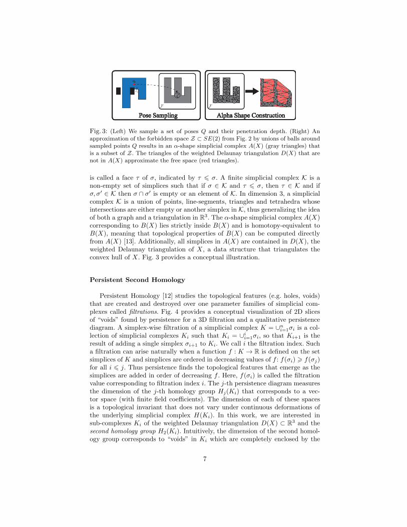
Fig. 3: (Left) We sample a set of poses Q and their penetration depth. (Right) Anapproximation of the forbidden space Z ⊂ SE(2) from Fig. 2 by unions of balls aroundsampled points Q results in an α-shape simplicial complex A(X) (gray triangles) thatis a subset of Z. The triangles of the weighted Delaunay triangulation D(X) that arenot in A(X) approximate the free space (red triangles).
is called a face τ of σ, indicated by τ 6 σ. A finite simplicial complex K is anon-empty set of simplices such that if σ ∈ K and τ 6 σ, then τ ∈ K and ifσ, σ′ ∈ K then σ ∩ σ′ is empty or an element of K. In dimension 3, a simplicialcomplex K is a union of points, line-segments, triangles and tetrahedra whoseintersections are either empty or another simplex in K, thus generalizing the ideaof both a graph and a triangulation in R3. The α-shape simplicial complex A(X)corresponding to B(X) lies strictly inside B(X) and is homotopy-equivalent toB(X), meaning that topological properties of B(X) can be computed directlyfrom A(X) [13]. Additionally, all simplices in A(X) are contained in D(X), theweighted Delaunay triangulation of X, a data structure that triangulates theconvex hull of X. Fig. 3 provides a conceptual illustration.
Persistent Second Homology
Persistent Homology [12] studies the topological features (e.g. holes, voids)that are created and destroyed over one parameter families of simplicial com-plexes called filtrations. Fig. 4 provides a conceptual visualization of 2D slicesof “voids” found by persistence for a 3D filtration and a qualitative persistencediagram. A simplex-wise filtration of a simplicial complex K = ∪ni=1σi is a col-lection of simplicial complexes Ki such that Ki = ∪ii=1σi, so that Ki+1 is theresult of adding a single simplex σi+1 to Ki. We call i the filtration index. Sucha filtration can arise naturally when a function f : K → R is defined on the setsimplices of K and simplices are ordered in decreasing values of f : f(σi) > f(σj)for all i 6 j. Thus persistence finds the topological features that emerge as thesimplices are added in order of decreasing f . Here, f(σi) is called the filtrationvalue corresponding to filtration index i. The j-th persistence diagram measuresthe dimension of the j-th homology group Hj(Ki) that corresponds to a vec-tor space (with finite field coefficients). The dimension of each of these spacesis a topological invariant that does not vary under continuous deformations ofthe underlying simplicial complex H(Ki). In this work, we are interested insub-complexes Ki of the weighted Delaunay triangulation D(X) ⊂ R3 and thesecond homology group H2(Ki). Intuitively, the dimension of the second homol-ogy group corresponds to “voids” in Ki which are completely enclosed by the
7
complex Ki. These voids in Ki can appear as we add new simplices with in-creasing i, or they can disappear as voids are filled in. The persistent secondhomology diagram enables us to visualize these topological changes. Each point(x, y) in the diagram corresponds to a pair of filtration indices (i, j) recordingthe fact that a void has “appeared” at index i and disappeared at index j. Fora geometric simplicial complex, these index pairs (i, j) correspond to simplices(σi, σj) where σj is a tetrahedron (a 3-simplex) which destroys or “fills in” avoid, while σi corresponds to a triangle (2-simplex) that corresponds to the lastcomplex needed to first create a fully enclosed void. The set of (i, j) pairs canbe displayed in the (index)-persistence diagram, or alternatively, when the fil-tration arises from a function f , we may display the set of points (f(σi), f(σj)).By considering the vertical distance |f(σi) − f(σj)| from the diagonal, we canread off the parameter range of f during which a void exists in the evolution ofthe filtration.
4 The EBCS-2D Algorithm
EBCS-2D (Algorithm 1) takes as input a polygonal object O, obstacle config-uration G, and potential function P , and outputs a set of energy-bounded cagesthat require nonzero energy to escape.
Using uniform sampling, the algorithm first generates s object poses incollision Q = {q1, ...,qs} and their corresponding penetration depths R ={r1, ..., rs}. We lift the poses to R3 and construct an α-shape approximationto the configuration space as described in Section 3. Next, we construct a filtra-tion by sorting all simplices in the free space in order of decreasing energy leveland use persistent homology to identify path components fully surrounded byu-energy forbidden space for all u thresholds. Finally, we examine the simpliceswithin each bounded component in order of increasing energy to check for acollision-free object pose, and return the poses extracted from each component.Fig. 4 illustrates the use of persistence in our algorithm.
Filtrations and Persistence from Energy Functions: To synthesize energy-bounded cages with persistence, we first order the simplices of the α-shape ap-proximation by decreasing energy level. We assumed that the potential P :SE(2) → R3 depends only on the translational component R2 of SE(2) andis concave on that space, which implies that . In this case, for any k-simplexσ = Conv(v0, . . . ,vk) ∈ D(X) − A(X) the maximum principle of convex opti-mization [5] implies that the minimum occurs at one of the vertices:
minx∈σ
P (π(x)) = min{P (π(v0)), . . . , P (π(vk))}
where π : R3 → SE(2) denotes the projection to SE(2). Using this fact, weconstruct a function D(X)→ R:
f(σ) =
{minx∈σ P (π(x)) σ ∈ D(X)−A(X)∞ σ ∈ A(X)
8
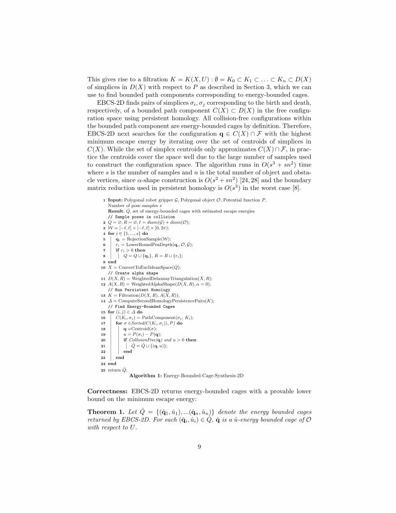
This gives rise to a filtration K = K(X,U) : ∅ = K0 ⊂ K1 ⊂ . . . ⊂ Kn ⊂ D(X)of simplices in D(X) with respect to P as described in Section 3, which we canuse to find bounded path components corresponding to energy-bounded cages.
EBCS-2D finds pairs of simplices σi, σj corresponding to the birth and death,respectively, of a bounded path component C(X) ⊂ D(X) in the free configu-ration space using persistent homology. All collision-free configurations withinthe bounded path component are energy-bounded cages by definition. Therefore,EBCS-2D next searches for the configuration q ∈ C(X) ∩ F with the highestminimum escape energy by iterating over the set of centroids of simplices inC(X). While the set of simplex centroids only approximates C(X)∩F , in prac-tice the centroids cover the space well due to the large number of samples usedto construct the configuration space. The algorithm runs in O(s3 + sn2) timewhere s is the number of samples and n is the total number of object and obsta-cle vertices, since α-shape construction is O(s2 + sn2) [24, 28] and the boundarymatrix reduction used in persistent homology is O(s3) in the worst case [8].
1 Input: Polygonal robot gripper G, Polygonal object O, Potential function P ,Number of pose samples sResult: Q, set of energy-bounded cages with estimated escape energies// Sample poses in collision
2 Q = ∅, R = ∅, ` = diam(G) + diam(O);3 W = [−`, `]× [−`, `]× [0, 2π);4 for i ∈ {1, ..., s} do5 qi = RejectionSample(W);6 ri = LowerBoundPenDepth(qi,O,G);7 if ri > 0 then8 Q = Q ∪ {qi}, R = R ∪ {ri};9 end
10 X = ConvertToEuclideanSpace(Q);// Create alpha shape
11 D(X,R) = WeightedDelaunayTriangulation(X,R);12 A(X,R) = WeightedAlphaShape(D(X,R), α = 0);
// Run Persistent Homology
13 K = Filtration(D(X,R), A(X,R));14 ∆ = ComputeSecondHomologyPersistencePairs(K);
// Find Energy-Bounded Cages
15 for (i, j) ∈ ∆ do16 C(Ki, σj) = PathComponent(σj , Ki);17 for σ ∈Sorted(C(Ki, σj)), P ) do18 q =Centroid(σ);19 u = P (σi)− P (q);20 if CollisionFree(q) and u > 0 then
21 Q = Q ∪ {(q, u)};22 end
23 end
24 end
25 return Q;Algorithm 1: Energy-Bounded-Cage-Synthesis-2D
Correctness: EBCS-2D returns energy-bounded cages with a provable lowerbound on the minimum escape energy:
Theorem 1. Let Q = {(q1, u1), ...(qn, un)} denote the energy bounded cagesreturned by EBCS-2D. For each (qi, ui) ∈ Q, q is a u-energy bounded cage of Owith respect to U .
9

Birth Index
Dea
th I
ndex
Decreasing Energy LevelGripper
Part
q1 q2 q1 q2 q2q1
σi
σj
i j
kpi
pj
pk
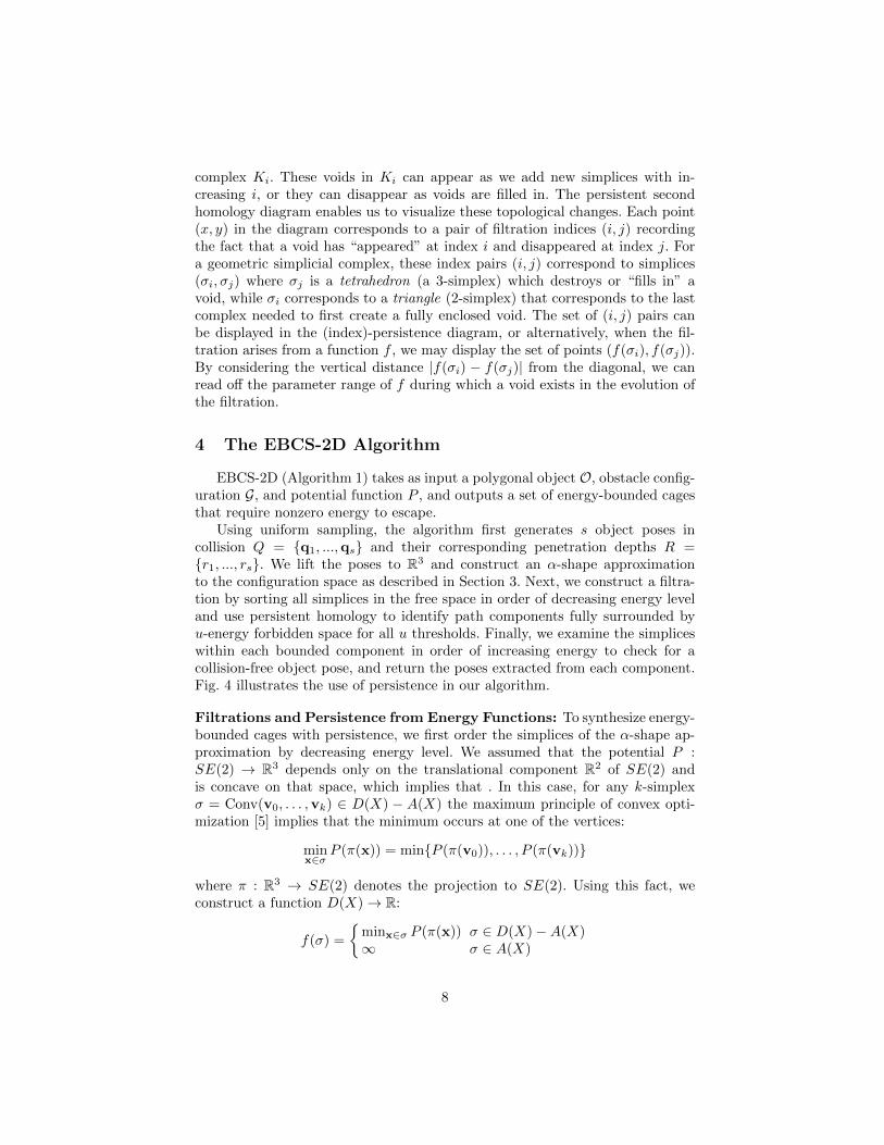
Fig. 4: Persistence diagram for ranking energy-bounded cages. Left: polygonal part andgripper polygons serve as input. We sample object poses X in collision and generatean α-shape representation (shown in gray in the three middle figures). Given an energypotential, we insert simplices in D(X)−A(X) in decreasing order of energy potential,creating a filtration of simplicial complexes. Voids (yellow and orange) are born withthe addition of edges σi and σj (red) at threshold potential levels pi and pj respectively,and die with the additions of the last triangle in each void at potential pk (red). Theassociated second persistence diagram (right figure) reveals voids with large persistencecorresponding to energy-bounded cages. In particular, configuration q1 is identified asmore persistent than configuration q2. There escape energy fof each configuration isequal to the difference in potentials: u1 = pk−pi and u2 = pk−pj , and by the filtrationordering this implies that q1 has higher escape energy than q2.
See the supplemental file at http://berkeleyautomation.github.io/caging/for a proof.
Extension to Pushing EBCS-2D can be applied to push grasping in thehorizontal plane. We use it to find push directions that yield robust energy-bounded cages by running EBCS-2D for a set of sampled push directions usingthe constant velocity linear push energy of Section 3. The extension runs EBCS-2D using P push angles uniformly sampled from [π2 − ϕ, π2 + ϕ] and returns aranked list of push directions and energy-bounded cages that can be reached bya linear, collision-free path along the push direction. While the potential changesfor each such push direction, the simplices only need to be re-sorted and thereforethe sampling and α-complex construction only need to be performed once.
5 Experiments
We implemented EBCS-2D in C++ and evaluated its performance on a setof polygonal objects under both gravitational and pushing energy fields. Weused CGAL [40] to compute α-shapes, the GJK-EPA algorithm of libccd [15] tocompute penetration depth, and the twist reduction algorithm implemented inPHAT [3] to compute the second persistence diagram. Our dataset consisted ofseven polygonal parts created by triangulating the projections of models fromYCB [6] and 3DNet [43] onto a plane. All experiments ran on an Intel Corei7-4770K 350GHz processor with 6 cores.
10
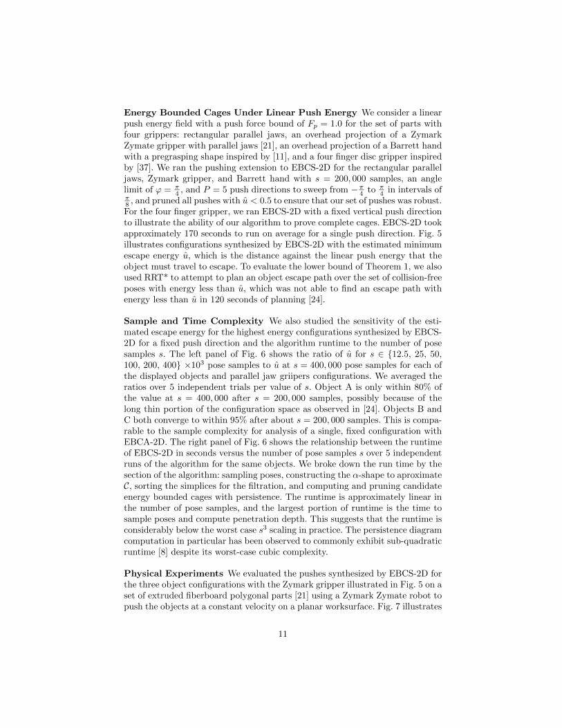
Energy Bounded Cages Under Linear Push Energy We consider a linearpush energy field with a push force bound of Fp = 1.0 for the set of parts withfour grippers: rectangular parallel jaws, an overhead projection of a ZymarkZymate gripper with parallel jaws [21], an overhead projection of a Barrett handwith a pregrasping shape inspired by [11], and a four finger disc gripper inspiredby [37]. We ran the pushing extension to EBCS-2D for the rectangular paralleljaws, Zymark gripper, and Barrett hand with s = 200, 000 samples, an anglelimit of ϕ = π
4 , and P = 5 push directions to sweep from −π4 to π4 in intervals of
π8 , and pruned all pushes with u < 0.5 to ensure that our set of pushes was robust.For the four finger gripper, we ran EBCS-2D with a fixed vertical push directionto illustrate the ability of our algorithm to prove complete cages. EBCS-2D tookapproximately 170 seconds to run on average for a single push direction. Fig. 5illustrates configurations synthesized by EBCS-2D with the estimated minimumescape energy u, which is the distance against the linear push energy that theobject must travel to escape. To evaluate the lower bound of Theorem 1, we alsoused RRT* to attempt to plan an object escape path over the set of collision-freeposes with energy less than u, which was not able to find an escape path withenergy less than u in 120 seconds of planning [24].
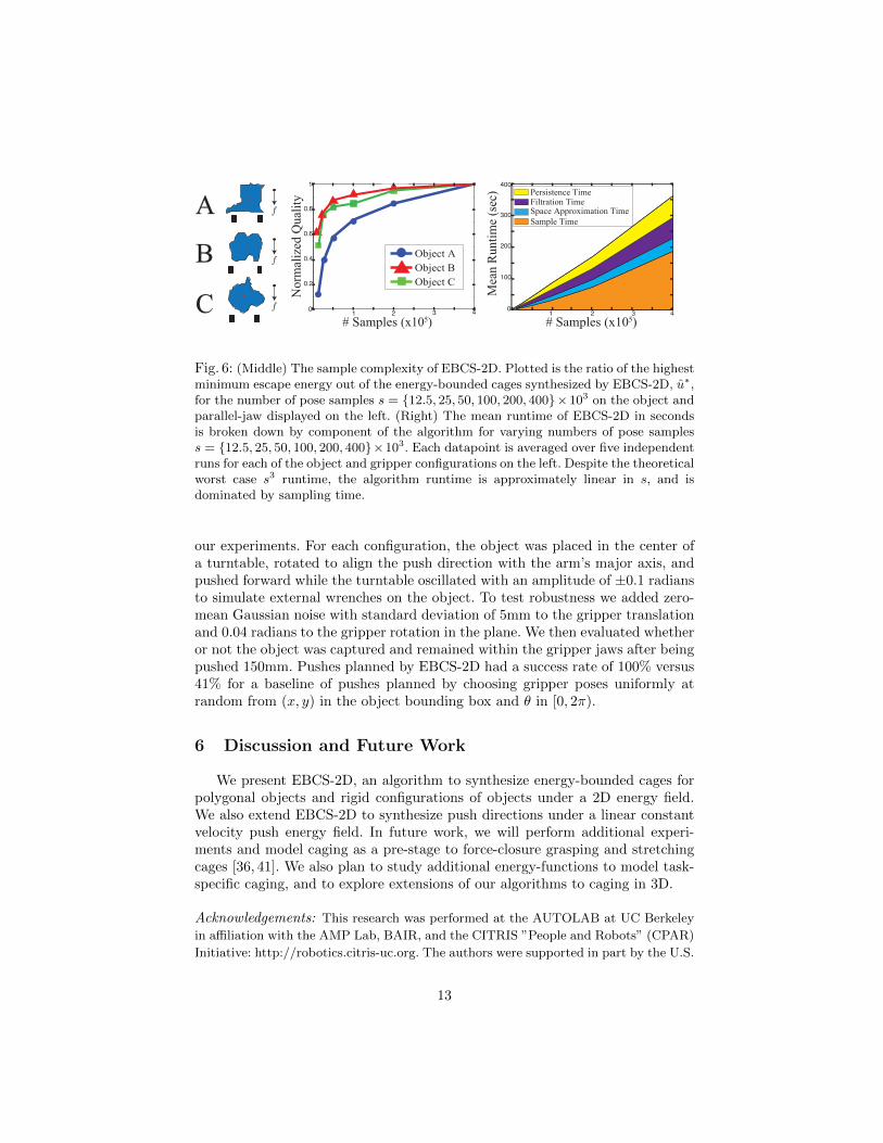
Sample and Time Complexity We also studied the sensitivity of the esti-mated escape energy for the highest energy configurations synthesized by EBCS-2D for a fixed push direction and the algorithm runtime to the number of posesamples s. The left panel of Fig. 6 shows the ratio of u for s ∈ {12.5, 25, 50,100, 200, 400} ×103 pose samples to u at s = 400, 000 pose samples for each ofthe displayed objects and parallel jaw griipers configurations. We averaged theratios over 5 independent trials per value of s. Object A is only within 80% ofthe value at s = 400, 000 after s = 200, 000 samples, possibly because of thelong thin portion of the configuration space as observed in [24]. Objects B andC both converge to within 95% after about s = 200, 000 samples. This is compa-rable to the sample complexity for analysis of a single, fixed configuration withEBCA-2D. The right panel of Fig. 6 shows the relationship between the runtimeof EBCS-2D in seconds versus the number of pose samples s over 5 independentruns of the algorithm for the same objects. We broke down the run time by thesection of the algorithm: sampling poses, constructing the α-shape to aproximateC, sorting the simplices for the filtration, and computing and pruning candidateenergy bounded cages with persistence. The runtime is approximately linear inthe number of pose samples, and the largest portion of runtime is the time tosample poses and compute penetration depth. This suggests that the runtime isconsiderably below the worst case s3 scaling in practice. The persistence diagramcomputation in particular has been observed to commonly exhibit sub-quadraticruntime [8] despite its worst-case cubic complexity.
Physical Experiments We evaluated the pushes synthesized by EBCS-2D forthe three object configurations with the Zymark gripper illustrated in Fig. 5 on aset of extruded fiberboard polygonal parts [21] using a Zymark Zymate robot topush the objects at a constant velocity on a planar worksurface. Fig. 7 illustrates
11
Configuration 1 Configuration 2 Configuration 3
f
f
Configuration 1 Configuration 2 Configuration 3
f
Configuration 1 Configuration 2 Configuration 3
f
f
f
f
f
f
f
f
f
f
f
Configuration 1 Configuration 2 Configuration 3
f ff
∞ ∞
∞∞∞
∞ ∞
f
f ff
fff
ff
3.082.572.00
1.26 1.86 2.46
2.60 6.700.81
f
2.332.001.32
f
2.16 4.78
1.22
f f
0.54 2.05
1.32
1.87
1.82 4.58
3.73 4.292.33
f
0.97 1.32 2.74
f f f
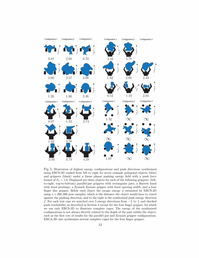
Fig. 5: Illustration of highest energy configurations and push directions synthesizedusing EBCS-2D ranked from left to right for seven example polygonal objects (blue)and grippers (black) under a linear planar pushing energy field with a push forcebound of Fp = 1.0. Displayed are three objects for each of the following grippers: (left-to-right, top-to-bottom) parallel-jaw grippers with rectangular jaws, a Barrett handwith fixed preshape, a Zymark Zymate gripper with fixed opening width, and a fourfinger disc gripper. Below each object the escape energy u estimated by EBCS-2Dusing s = 200, 000 pose samples, which is the distance the object would have to travelagainst the pushing direction, and to the right is the synthesized push energy directionf . For each test case we searched over 5 energy directions from −π
4to π
4and checked
push reachability as described in Section 4 except for the four finger gripper, for whichwe ran only EBCS-2D to illustrate complete cages. The energy of the synthesizedconfigurations is not always directly related to the depth of the part within the object,such as the first row of results for the parallel jaw and Zymark gripper configurations.EBCA-2D also synthesizes several complete cages for the four finger gripper.
12
# Samples (x105)
Mea
n R
un
tim
e (s
ec)
Sample Time
Space Approximation TimeFiltration TimePersistence Time
# Samples (x105)
No
rmal
ized
Qu
alit
y
Object A
Object B
Object C
1 3 40
100
200
300
400
21 2 3 40
0.2
0.4
0.6
0.8
1
A
B
C
f
f
f
Fig. 6: (Middle) The sample complexity of EBCS-2D. Plotted is the ratio of the highestminimum escape energy out of the energy-bounded cages synthesized by EBCS-2D, u∗,for the number of pose samples s = {12.5, 25, 50, 100, 200, 400}×103 on the object andparallel-jaw displayed on the left. (Right) The mean runtime of EBCS-2D in secondsis broken down by component of the algorithm for varying numbers of pose sampless = {12.5, 25, 50, 100, 200, 400}×103. Each datapoint is averaged over five independentruns for each of the object and gripper configurations on the left. Despite the theoreticalworst case s3 runtime, the algorithm runtime is approximately linear in s, and isdominated by sampling time.
our experiments. For each configuration, the object was placed in the center ofa turntable, rotated to align the push direction with the arm’s major axis, andpushed forward while the turntable oscillated with an amplitude of ±0.1 radiansto simulate external wrenches on the object. To test robustness we added zero-mean Gaussian noise with standard deviation of 5mm to the gripper translationand 0.04 radians to the gripper rotation in the plane. We then evaluated whetheror not the object was captured and remained within the gripper jaws after beingpushed 150mm. Pushes planned by EBCS-2D had a success rate of 100% versus41% for a baseline of pushes planned by choosing gripper poses uniformly atrandom from (x, y) in the object bounding box and θ in [0, 2π).
6 Discussion and Future Work
We present EBCS-2D, an algorithm to synthesize energy-bounded cages forpolygonal objects and rigid configurations of objects under a 2D energy field.We also extend EBCS-2D to synthesize push directions under a linear constantvelocity push energy field. In future work, we will perform additional experi-ments and model caging as a pre-stage to force-closure grasping and stretchingcages [36, 41]. We also plan to study additional energy-functions to model task-specific caging, and to explore extensions of our algorithms to caging in 3D.
Acknowledgements: This research was performed at the AUTOLAB at UC Berkeley
in affiliation with the AMP Lab, BAIR, and the CITRIS ”People and Robots” (CPAR)
Initiative: http://robotics.citris-uc.org. The authors were supported in part by the U.S.
13
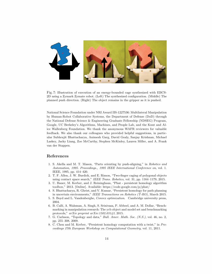
Fig. 7: Illustration of execution of an energy-bounded cage synthesized with EBCS-2D using a Zymark Zymate robot. (Left) The synthesized configuration. (Middle) Theplanned push direction. (Right) The object remains in the gripper as it is pushed.
National Science Foundation under NRI Award IIS-1227536: Multilateral Manipulation
by Human-Robot Collaborative Systems, the Department of Defense (DoD) through
the National Defense Science & Engineering Graduate Fellowship (NDSEG) Program,
Google, UC Berkeley’s Algorithms, Machines, and People Lab, and the Knut and Al-
ice Wallenberg Foundation. We thank the anonymous WAFR reviewers for valuable
feedback. We also thank our colleagues who provided helpful suggestions, in partic-
ular Subhrajit Bhattacharya, Animesh Garg, David Gealy, Sanjay Krishnan, Michael
Laskey, Jacky Liang, Zoe McCarthy, Stephen McKinley, Lauren Miller, and A. Frank
van der Stappen.
References
1. S. Akella and M. T. Mason, “Parts orienting by push-aligning,” in Robotics andAutomation, 1995. Proceedings., 1995 IEEE International Conference on, vol. 1.IEEE, 1995, pp. 414–420.
2. T. F. Allen, J. W. Burdick, and E. Rimon, “Two-finger caging of polygonal objectsusing contact space search,” IEEE Trans. Robotics, vol. 31, pp. 1164–1179, 2015.
3. U. Bauer, M. Kerber, and J. Reininghaus, “Phat - persistent homology algorithmtoolbox,” 2013. [Online]. Available: https://code.google.com/p/phat/
4. S. Bhattacharya, R. Ghrist, and V. Kumar, “Persistent homology for path planningin uncertain environments,” IEEE Transactions on Robotics (T-RO), March 2015.
5. S. Boyd and L. Vandenberghe, Convex optimization. Cambridge university press,2004.
6. B. Calli, A. Walsman, A. Singh, S. Srinivasa, P. Abbeel, and A. M. Dollar, “Bench-marking in manipulation research: The ycb object and model set and benchmarkingprotocols,” arXiv preprint arXiv:1502.03143, 2015.
7. G. Carlsson, “Topology and data,” Bull. Amer. Math. Soc. (N.S.), vol. 46, no. 2,pp. 255–308, 2009.
8. C. Chen and M. Kerber, “Persistent homology computation with a twist,” in Pro-ceedings 27th European Workshop on Computational Geometry, vol. 11, 2011.
14

9. R. Diankov, S. S. Srinivasa, D. Ferguson, and J. Kuffner, “Manipulation planningwith caging grasps,” in Humanoid Robots, 2008. Humanoids 2008. 8th IEEE-RASInternational Conference on. IEEE, 2008, pp. 285–292.
10. M. Dogar, K. Hsiao, M. Ciocarlie, and S. Srinivasa, “Physics-based grasp planningthrough clutter,” in Robotics: Science and Systems VIII, 2012.
11. M. Dogar and S. Srinivasa, “A framework for push-grasping in clutter,” Robotics:Science and systems VII, vol. 1, 2011.
12. H. Edelsbrunner and J. Harer, “Persistent homology-a survey,” Contemporarymathematics, vol. 453, pp. 257–282, 2008.
13. H. Edelsbrunner, Weighted alpha shapes. University of Illinois at Urbana-Champaign, Department of Computer Science, 1992.
14. H. Edelsbrunner and J. Harer, Computational topology: an introduction. AmericanMathematical Soc., 2010.
15. D. Fiser, “libccd - collision detection between convex shapes,” http://libccd.danfis.cz/.
16. D. C. Giancoli, Physics: principles with applications. Pearson Education, 2005.17. K. Y. Goldberg, “Orienting polygonal parts without sensors,” Algorithmica, vol. 10,
no. 2-4, pp. 201–225, 1993.18. M. C. Koval, N. S. Pollard, and S. S. Srinivasa, “Pre-and post-contact policy de-
composition for planar contact manipulation under uncertainty,” The InternationalJournal of Robotics Research, vol. 35, no. 1-3, pp. 244–264, 2016.
19. W. Kuperberg, “Problems on polytopes and convex sets,” in DIMACS Workshopon polytopes, 1990, pp. 584–589.
20. T. H. Kwok, W. Wan, J. Pan, C. C. Wang, J. Yuan, K. Harada, and Y. Chen,“Rope caging and grasping,” in Proc. IEEE Int. Conf. Robotics and Automation(ICRA), 2016.
21. M. Laskey, J. Lee, C. Chuck, D. Gealy, W. Hsieh, F. T. Pokorny, A. D. Dragan,and K. Goldberg, “Robot grasping in clutter: Using a hierarchy of supervisors forlearning from demonstrations,” in Proc. IEEE Conf. on Automation Science andEngineering (CASE). IEEE, 2016.
22. S. M. LaValle, Planning algorithms. Cambridge university press, 2006.23. K. M. Lynch and M. T. Mason, “Controllability of pushing,” in Robotics and
Automation, 1995. Proceedings., 1995 IEEE International Conference on, vol. 1.IEEE, 1995, pp. 112–119.
24. J. Mahler, F. T. Pokorny, A. F. van der Stappen, and K. Goldberg, “Energy-bounded caging: Formal definition and 2d lower bound algorithm based on weightedalpha shapes,” in IEEE Robotics & Automation Letters. IEEE, 2016.
25. T. Makapunyo, T. Phoka, P. Pipattanasomporn, N. Niparnan, and A. Sudsang,“Measurement framework of partial cage quality based on probabilistic motionplanning,” in IEEE Int. Conf. on Robotics and Automation (ICRA), 2013, pp.1574–1579.
26. M. T. Mason, “Mechanics and planning of manipulator pushing operations,” TheInternational Journal of Robotics Research, vol. 5, no. 3, pp. 53–71, 1986.
27. ——, Mechanics of Robotic Manipulation. Cambridge, MA, USA: MIT Press,2001.
28. Z. McCarthy, T. Bretl, and S. Hutchinson, “Proving path non-existence usingsampling and alpha shapes,” in Robotics and Automation (ICRA), 2012 IEEEInternational Conference on. IEEE, 2012, pp. 2563–2569.
29. R. M. Murray, Z. Li, and S. S. Sastry, A mathematical introduction to roboticmanipulation. CRC press, 1994.
15
30. M. A. Peshkin and A. C. Sanderson, “The motion of a pushed, sliding workpiece,”IEEE Journal on Robotics and Automation, vol. 4, no. 6, pp. 569–598, 1988.
31. F. T. Pokorny, M. Hawasly, and S. Ramamoorthy, “Multiscale topological trajec-tory classification with persistent homology,” in Proceedings of Robotics: Scienceand Systems, July 2014.
32. F. T. Pokorny and D. Kragic, “Data-driven topological motion planning with per-sistent cohomology,” in Proceedings of Robotics: Science and Systems, Rome, Italy,July 2015.
33. F. T. Pokorny, J. A. Stork, and D. Kragic, “Grasping objects with holes: A topo-logical approach,” in Proc. of the IEEE International Conference on Robotics andAutomation (ICRA), Karlsruhe, Germany, 2013.
34. E. Rimon and A. Blake, “Caging 2d bodies by 1-parameter two-fingered grippingsystems,” in Proc. IEEE Int. Conf. Robotics and Automation (ICRA), 1996, pp.1458–1464.
35. E. Rimon and J. W. Burdick, “Mobility of bodies in contact. i. A 2nd-order mobilityindex for multiple-finger grasps,” vol. 14, no. 5, 1998, pp. 696–708.
36. A. Rodriguez, M. T. Mason, and S. Ferry, “From caging to grasping,” Int. J.Robotics Research (IJRR), pp. 1–15, 2012.
37. J. Su, H. Qiao, Z. Ou, and Z.-Y. Liu, “Vision-based caging grasps of polyhedron-likeworkpieces with a binary industrial gripper,” IEEE Transactions on AutomationScience and Engineering, vol. 12, no. 3, pp. 1033–1046, 2015.
38. A. Sudsang and J. Ponce, “On grasping and manipulating polygonal objects withdisc-shaped robots in the plane,” in Proc. IEEE Int. Conf. Robotics and Automa-tion (ICRA), 1998, pp. 2740–2746.
39. ——, “A new approach to motion planning for disc-shaped robots manipulatinga polygonal object in the plane,” in Robotics and Automation, 2000. Proceedings.ICRA’00. IEEE International Conference on, vol. 2. IEEE, 2000, pp. 1068–1075.
40. The CGAL Project, CGAL User and Reference Manual, 4th ed. CGAL EditorialBoard, 2015.
41. M. Vahedi and A. F. van der Stappen, “Caging polygons with two and threefingers,” The International Journal of Robotics Research, vol. 27, no. 11-12, pp.1308–1324, 2008.
42. W. Wan, R. Fukui, M. Shimosaka, T. Sato, and Y. Kuniyoshi, “A new graspingby caging solution by using eigen-shapes and space mapping,” in Proc. IEEE Int.Conf. Robotics and Automation (ICRA). IEEE, 2013, pp. 1566–1573.
43. W. Wohlkinger, A. Aldoma, R. B. Rusu, and M. Vincze, “3dnet: Large-scale ob-ject class recognition from cad models,” in Proc. IEEE Int. Conf. Robotics andAutomation (ICRA), 2012, pp. 5384–5391.
44. L. Zhang, Y. J. Kim, and D. Manocha, “Efficient cell labelling and path non-existence computation using c-obstacle query,” The International Journal ofRobotics Research, vol. 27, no. 11-12, pp. 1246–1257, 2008.
16