synthesis of novel zinc anode via electroplating for
TRANSCRIPT

Synthesis of Novel Zinc Anode via Electroplating for
Rechargeable Hybrid Aqueous Batteries
by
Kyung Eun Kate Sun
A thesis
presented to the University of Waterloo
in fulfillment of the
thesis requirement for the degree of
Mater of Applied Science
in
Chemical Engineering
Waterloo, Ontario, Canada, 2016
© Kyung Eun Kate Sun 2016

ii
AUTHOR’S DECLARATION
I hereby declare that I am the sole author of this thesis. This is a true copy of the thesis, including
any required final revisions, as accepted by my examiners.
I understand that my thesis may be made electronically available to the public.

iii
ABSTRACT
With the rise of the environmental concerns from combustion of fossil fuels, the demand for the
alternative clean energy sources has increased. One of the alternatives is rechargeable batteries.
Among many types of rechargeable batteries, lithium-ion batteries have been the most promising
due to the high energy density and long lifespan. The current lithium-ion batteries, however, hold
a drawback as they utilize organic electrolytes. The use of organic electrolytes not only raises
safety and environmental concerns, but also results in a higher manufacturing cost than would be
with aqueous electrolytes. Therefore, these issues can be solved by replacing the organic
electrolytes with aqueous electrolytes. Among the many types of lithium-ion batteries with
aqueous electrolytes, Rechargeable Hybrid Aqueous Battery (ReHAB) was selected in this project.
ReHAB utilizes lithium manganese oxide (LiMn2O4) as the cathode and zinc as the anode.
LiMn2O4 is a good candidate because tightly bounded lithium ions make LiMn2O4 stable in air and
water. Also, it shows a small volume variation between lithiated and non-lithiated states. Zinc
metal was chosen because of its low redox potential, good reversibility, high over-potential for
hydrogen evolution in acidic environment, large specific capacity, good corrosion resistance, and
cost effectiveness.
While ReHAB is free of the problems posed by organic electrolytes in traditional Li-ion batteries,
the current ReHAB technology must be improved to perform competitively in market. More
specifically regarding the zinc anode, there are issues of corrosion, dendrite formation, and
hydrogen evolution. Therefore, the goal of this project was to synthesize novel zinc anodes via
electroplating with additives (organic and inorganic) reported in literature to mitigate issues of
corrosion, dendrite formation, and hydrogen evolution (side reactions). The selected organic
additives were cetyl trimethylammonium bromide (CTAB), sodium dodecyle sulfate (SDS),
polyethylene glycol 8000 (PEG), and thiourea; and the inorganic additives were indium (II) sulfate,
tin (IV) oxide, and boric acid. Each anode was characterized by the following measurements to
rate its performance: float current (for side reactions), corrosion current, cyclability, x-ray
diffraction (for crystalline structure and indication of high/low deposition efficiency), and
scanning electron microscope (for morphology).
All the anodes created with the inorganic and almost all with the organic additives performed better
than the commercial zinc anode. Among the organic additives tested, Zn-SDS performed the best,
with the lowest float current and corrosion current measurements and the highest retention of 79%
at the end of its 1000th cycle. Among the inorganic additives tested, each fared very similarity,
with similar float current and corrosion rate, and retaining in average 78% of the initial discharge
capacity at the end of 1000th cycle.
Between the organic and inorganic additives, however, the XRD results suggested that in general
the zinc deposition efficiencies may be lower for inorganic additives (and thus less favourable
when scaling up for commercial production). If the lower current efficiency of inorganic additives
(hinted by the XRD results) is verified to be true, then the organic additives that either performed

iv
better than or as well as the inorganic additives would be the better choice for the next generation
of ReHAB.

v
ACKNOWLEGEMENTS
I would like to sincerely thank my supervisor Dr. P. Chen for the opportunity he has provided me,
and his support and guidance throughout my Master’s studies. His invaluable advice has guided
me to grow as a researcher and to be able to reach to the point where I am now.
I also would like to thank Dr. Yongguang (Wiley) Zhang and Yan Zhao for being wonderful
mentors and showing me how exiting research can be. My sincere thanks also go to the past and
current lab members in Dr. Chen’s group for their guidance, training, and support: Xiao (Sunny)
Zhu, Yan (Ryan) Yu, Ye Tian, Dr. Yang Liu, Dr. Alireza Zehtab Yazdi. Dr. Xianwen Wu, Aishuak
Konarov, Dr. Hongbin Zhao. I’m also thankful to my friends, Junghwa Yun, Sung Eun Kim, Yung
Priscilla Li, Kathy Wang, Kyungsil (Leah) Chung, Sherriza Khan, and Nagma Zerin for making
my graduate life unforgettable.
As well, I very much thank Dr. Tuan K.A. Hoang and Dr. The Nam Long Doan for providing me
a thorough feedback on my thesis. Their warm encouragement and guidance have taught me how
to become a better researcher.
Finally I’m very grateful to my God for giving me the strength and wisdom throughout my
graduate studies and complete another chapter of my life. I also owe my deepest gratitude to my
beloved parents and my brother for their endless love, encouragement, and support.

vi
DEDICATION
Dedicated to My Family

vii
Table of Contents
AUTHOR’S DECLARATION ..................................................................................................................... ii
ABSTRACT ................................................................................................................................................. iii
ACKNOWLEGEMENTS ............................................................................................................................. v
List of Figures .............................................................................................................................................. ix
List of Tables ................................................................................................................................................ x
Chapter 1: Introduction of Thesis ................................................................................................................. 1
1.1 Research Motivation ........................................................................................................................... 1
1.2 Research Objectives ............................................................................................................................ 2
1.3 Outline of Thesis ................................................................................................................................. 3
Chapter 2: Introduction to ReHAB and Problems of Anode ........................................................................ 4
2.1 History of Rechargeable Aqueous Batteries ....................................................................................... 4
2.2 Rechargeable Hybrid Aqueous Batteries ............................................................................................ 5
2.3 Zinc Anode in Rechargeable Hybrid Aqueous Batteries .................................................................... 6
2.3.1 Behaviour of Zinc Metal in Various Environments ..................................................................... 8
2.4 Synthesis of Zinc Anode ................................................................................................................... 13
2.4.1 Electroplating ............................................................................................................................. 14
2.5 Additives ........................................................................................................................................... 18
2.5.1 Fundamentals/Mechanisms of Additives ................................................................................... 18
2.5.2 Categories of Additives .............................................................................................................. 20
2.6 Physical Characterization Techniques .............................................................................................. 21
2.6.1 X-ray Diffraction (XRD) ........................................................................................................... 21
2.6.2 Scanning Electron Microscopy (SEM) ...................................................................................... 22
2.7 Electrochemical Characterization Techniques .................................................................................. 22
2.7.1 Float Current .............................................................................................................................. 22
2.7.2 Corrosion Test ............................................................................................................................ 22
2.7.2 Galvanostatic Charge-Discharge ................................................................................................ 24
Chapter 3. Synthesis of Zinc via Electroplating with Additives ................................................................. 26
3.1 Introduction ....................................................................................................................................... 26
3.2 Experimental Procedures .................................................................................................................. 27
3.2.1 Battery Components ................................................................................................................... 27
3.2.2 Anode Preparation...................................................................................................................... 27

viii
3.2.3 Characterization Technique Conditions ..................................................................................... 29
3.3 Result and Discussion ....................................................................................................................... 30
3.3.1 Determining Zinc Electroplating Condition............................................................................... 30
3.3.2 Treatment of Brass Foil.............................................................................................................. 33
3.3.3 Comparison of Two Substrates – Graphite and Brass Foils....................................................... 35
3.3.4 Optimal Additive Concentrations .............................................................................................. 36
3.3.5 Effect of Organic Additives ....................................................................................................... 40
3.3.6 Effect of Inorganic Additives ..................................................................................................... 48
3.4 Conclusion ........................................................................................................................................ 54
Chapter 4. Future Work .............................................................................................................................. 56
References ................................................................................................................................................... 57

ix
List of Figures
Figure 1 - Comparison of the different battery technologies in terms of volumetric and gravimetric
energy density [2] ......................................................................................................................................... 1
Figure 2 - Pourbaix (EpH) diagram of zinc in water at 25°C [28] ................................................................. 9
Figure 3 - Pourbaix diagram of Zn, LiMn2O4, and LiFePO4 [3] (supplementary document) .................. 10
Figure 4 - Phase diagram of zinc-oxide at the different temperatures [26] ................................................ 12
Figure 5 - Zinc plating with (A) no additive, (B) NP16, (C) NP16 and S40, (D) NP16 and OCBA, and
(D) NP16, OCBA, and S40 [34] ................................................................................................................. 15
Figure 6 - Hull cell experimental setup (A) front view of the actual experimental setup showing the
external connection (B) side view and (C) top view ................................................................................... 16
Figure 7 - Zinc deposited on a graphite foil via Hull cell experiment ....................................................... 17
Figure 8 - (A) Schematic of x-radiation for a simple crystal lattice (B) Relationship between the Bragg
angle and experimentally measured diffraction angle[60] .......................................................................... 21
Figure 9 - Tafel curve with line extrapolation indicating corrosion parameters [61] ................................ 23
Figure 10 - (a) A typical galvanostatic charge and discharge profile of ReHAB operated at 4C (b)
cyclability and coulombic efficiency of ReHAB with undoped LiMn2O4 [3] ............................................ 24
Figure 11 - Schematics of parallel cell (a) front and (b) top view ............................................................. 28
Figure 12 - Cyclaiblity of ReHAB with synthesized zinc anodes electroplated at current densities of 30,
50, 80 mA/cm2 for 10min and commercial zinc foil (Commercial) ........................................................... 32
Figure 13 - Cyclaiblity of ReHAB with synthesized zinc anodes electroplated at 50mA/cm2 for
deposition time of 6, 8, 10, 15, 20min and commercialized zinc foil (Commercial) .................................. 33
Figure 14 - Result of the discharge capacity retention and the cyclability plot from ReHAB with brass
foil substrate exposed to different treatments (Hull cell result) .................................................................. 34
Figure 15 - Result of the discharge capacity retention and the cyclability plots from ReHAB with brass
foil substrate exposed to different treatments (Parallel cell result) ............................................................. 35
Figure 16 - Result of the discharge capacity retention and the cyclability plots from ReHAB with graphite
and brass foil as anode substrates (Hull cell result) .................................................................................... 36
Figure 17 - SEM images of zinc deposits with 0 (no additive), 50, 100, and 500ppm of boric acid in
electroplating bath (magnification 1k) ........................................................................................................ 37
Figure 18 - Float current of ReHAB with electroplated anode with 0, 50, 100, and 500ppm of boric acid
in electroplating bath ................................................................................................................................... 38
Figure 19 - XRD of zinc electroplated (A) without additives and (B) with 100ppm of boric acid ........... 39
Figure 20 - XRD and SEM images of the commerciali zinc foil ............................................................... 41
Figure 21 - XRD of the electroplated zinc without any additives at low and high current densities. For
lower current density XRD was obtained from Hull cell, and the high current density from parallel cell . 41
Figure 22 - XRD results of the zinc anode electroplated with organic additives ....................................... 42
Figure 23 - SEM images of synthesized anode with organic additives (magnification 5k) ....................... 44
Figure 24 - Float current of ReHAB with zinc deposited with/without organic additives and
commercialized zinc foil ............................................................................................................................. 45
Figure 25 - Retention and cyclability of the ReHAB with zinc anode with organic additives and
commercialized zinc foil ............................................................................................................................. 47
Figure 26 - XRD results of the zinc anode electroplated with inorganic additives .................................... 49
Figure 27 - SEM images of synthesized anode with inorganic additives (magnification 2k) .................... 50
Figure 28 - Float current of ReHAB with zinc deposited with inorganic additives and commercialized
zinc foil ....................................................................................................................................................... 51

x
Figure 29 - Retention and cyclability of the ReHAB with zinc anode with inorganic additives and
commercialized zinc foil ............................................................................................................................. 52
List of Tables
Table 1 - Summary of deposited samples with zinc deposition time and corresponding current densities 31
Table 2 - Summary of the deposited samples with their zinc deposition time and corresponding current
densities ...................................................................................................................................................... 32
Table 3 - Summary of corrosion potential and current of the electroplated anode with 0, 50, 100, and
500ppm of boric acid in electroplating bath ............................................................................................... 38
Table 4 - Corrosion potential and current for the synthesized zinc with and without organic additives and
commercialized zinc foil ............................................................................................................................. 46
Table 5 - Corrosion potential and current for the synthesized zinc with inorganic additives and
commercialized zinc foil ............................................................................................................................. 52

xi
List of Abbreviations, Symbols, and Nomenclature
AGM Absorptive Glass Mat
CTAB Cetyl Trimethylammonium Bromide
FESEM Field Emission Scanning Electron Microscopy
I Total Current
Icorr Corrosion Current
j Current Density
icorr Corrosion Current Density
L Distance
NMP 1-methyl-2-pyrrolidinone
OCV Open Circuit Voltage
PEG Polyethylene Glycol 8000
PPM Parts Per Million
PVDF Polyvinylidene Fluoride
ReHAB Rechargeable Hybrid Aqueous Battery
SHE Standard Hydrogen Electrode
SDS Sodium Dodecyle Sulfate
V Voltage
Vcorr Corrosion Potential
XRD X-ray Diffraction
𝛽𝑎 Anodic Tafel Constant
𝛽𝑐 Cathodic Tafel Constant

1
Chapter 1: Introduction of Thesis
1.1 Research Motivation
Since the eighteenth century, fossil fuels have been an excellent energy source in many
applications. They, however, have since raised environmental concerns due to their harmful
combustion wastes and fast depletion rate. The combustion products, such as carbon dioxide and
sulphur dioxide, contributed to the global warming, and some have predicted that the oil and gas
will deplete in less than 40 years [1]. The search for and the development of the cleaner energy
sources have been – and still are – actively pursued. And out of many approaches, the area of
chemical rechargeable batteries (also called secondary batteries) has garnered much interest and
investment as is evident today in their ubiquitousness for their storage capacities, reduction in
material waste as well as pollution/by-products.
The first battery was invented in 1800 by Volta, and in 1895, the idea and demonstration of a
rechargeable battery were carried out by Gaston Planté. Since then, various types of secondary
batteries have been proposed, such as nickel-cadmium, nickel-metal-hydride, and lithium-ion
batteries. Among these different batteries, lithium-ion batteries have been the most promising due
to the high energy density (shown in Figure 1) and long lifespan [2, 3].
Figure 1 - Comparison of the different battery technologies in terms of volumetric and gravimetric energy density [2]

2
Despite the many advantages of traditional lithium-ion batteries, there is one major drawback –
the use of organic electrolytes. With organic electrolytes, the lithium-ion batteries can be operated
at a wide voltage range, but due to the flammable and toxic characteristics of the organic
electrolytes, safety and environmental concerns arise with the leakage of the electrolytes [3].
Moreover, the manufacturing with organic electrolytes is complicated and expensive as they are
moisture- and air- sensitive [3, 4]. Thus, the organic electrolytes can be replaced with aqueous
electrolytes to solve these problems. Among different kinds of aqueous batteries, Rechargeable
Hybrid Aqueous Battery (ReHAB) was selected for this report. ReHAB, as any other proposed
batteries, still needs some improvements. In this report, the studies on the anode to improve the
performance of ReHAB are presented.
1.2 Research Objectives
The project goal was to develop novel zinc anodes via electroplating to improve upon the current
ReHAB technology operating with a commercialize zinc anode. The commercialized zinc anode
in ReHAB faces many problems, such as corrosion, dendrite formation, and hydrogen evolution
[5]. Therefore, the goal was to create novel anodes by employing various additives, known to
mitigate the aforementioned problems, during the synthesis of the zinc anode. For this study, 7
different additives were selected: CTAB, SDS, PEG, thiourea, tin oxide, boric acid, and indium
sulfate.
The crystalline structures of the zinc deposited with the additives were studied with XRD to
understand how each additive modified the structure. Their morphologies were observed with
SEM. To determine whether they assisted in alleviating the current zinc problems in ReHAB, the
corrosion and battery tests were carried out. Lastly, to examine if these electroplated anodes could
replace the commercialized zinc foil in ReHAB, the batteries were assembled with the synthesized
anode and tested.

3
1.3 Outline of Thesis
This thesis contains 4 chapters:
Chapter 1 contains the overview and the research objectives
Chapter 2 includes the literature review on the aqueous batteries, introduction to
electroplating, and fundamentals of additives
Chapter 3 presents the experimental methodologies, technique used for sample
analysis, experimental data and analysis, and conclusion
Chapter 4 contains the future work

4
Chapter 2: Introduction to ReHAB and Problems of Anode
2.1 History of Rechargeable Aqueous Batteries
With the rise of the environmental concerns with the combustion wastes from fossil fuels, the
demand for the alternative renewable energy sources has also increased. One of the cleanest energy
sources is the secondary batteries. Among the many types of rechargeable batteries, lithium-ion
batteries are one of the most promising batteries as they show high energy density and long lifespan.
They can also operate at a wide electrochemical stability window (voltage range at which
substance is stable) of 3-5V [3]. Hence, they have been used in various applications, such as
portable electronics and vehicles.
Despite these advantages, there is a drawback of lithium-ion batteries due to its use of the
traditional organic electrolytes. The organic electrolytes are highly toxic and flammable.
Moreover, the manufacturing cost of the lithium-ion batteries is expensive due to the organic
electrolytes being moisture- and air- sensitive. In order to mitigate these issues, the employment
of aqueous electrolytes can be made. Although, the aqueous electrolytes show smaller
electrochemical stability window in comparison to the organic electrolytes, they can guarantee
safety, environmentally friendliness, and reduced manufacturing cost.
In 1994, Dahn and colleague [6] introduced the first aqueous rechargeable lithium-ion battery
(ARLB), which consisted of lithium manganese oxide (LiMn2O4) as the negative electrode (or
anode) and carbon rod as the positive electrode (or cathode). During the charge process, the lithium
ions de-intercalated from the positive electrode (or cathode) and intercalated into the negative
electrode (or anode), and vice versa during the discharge process. The authors determined that the
electrodes were stable in the potential range of 2.3V ≤ V(x) ≤ 3.5V when ARLB consisted of 1M
LiOH as the electrolyte [6]. The ARLB demonstrated higher operating voltage than the lead-acid
battery, but poorer battery cycling performance [7, 8].
Since the invention of ARLB, other types of ARLB were also introduced. In 2007, G.J. Wang et
al. [9] studied ARLB with lithium trivandate (LiV3O8) anode and LiMn2O4 cathode operating in
2M lithium sulfate electrolyte (Li2SO4). The authors confirmed that both of the synthesized
electrodes were stable in the aqueous solution, and the batteries with these electrodes produced the

5
1st coulombic efficiency of 89.2%, and the retention of 53.5% after 100th cycle [9]. These results
indicated the improvements of ARLB in comparison to those reported in the earlier literature.
J. Luo’s group [10] studied the effect oxygen in an aqueous electrolyte in the aqueous rechargeable
batteries. The battery was composed of lithium iron phosphate (LiFePO4) as the cathode, lithium
titanium phosphate (LiTi2(PO4)3) as the anode, and Li2SO4 as the electrolyte. By removing the
oxygen from the electrolyte, the batteries were able to retain over 90% of capacity until 1000
cycles [10]. With the presence of oxygen, however, the capacity of the battery faded quickly. These
results demonstrated that the absence of the oxygen in the electrolyte prolonged the cyclability of
the batteries due to the reduced chance of the anode reacting with the oxygen.
2.2 Rechargeable Hybrid Aqueous Batteries
Out of many types of aqueous batteries, Rechargeable Hybrid Aqueous Battery (or ReHAB) was
selected for this project. ReHAB, invented in 2012 by Chen’s research group, utilizes LiMn2O4 as
the cathode, zinc foil as the anode, and a chloride solution containing lithium and zinc ions as the
electrolyte. The combination of the cathode and the anode produces the battery voltage of ~1.8V
[3]. The battery delivers the energy density of 50-80 Wh kg-1, which is higher than that of the lead-
acid battery (30-50 Wh kg-1), the one with an aqueous electrolyte currently used in the practical
applications [3]. Also, ReHAB could run up to 1000 cycles with 90% of its original capacity.
The mechanism of ReHAB is more complex as two ions – zinc as well as lithium ions – take a part
during cycling of the batteries. During the charge process, lithium ions are de-intercalated from
the cathode as shown in the following reaction:
LiMn2O4 → Li1-xMn2O4 + xLi+ + xe- (1)
Simultaneously, zinc ions in the electrolyte are deposited on the anode:
Zn2+ + 2e- → Zn (2)
The reverse reactions of (1) and (2) are expected during the discharge process.
If the batteries were operated ideally, the current efficiencies of chemical reaction (1) and (2)
would be 100% each. But, in reality, side reactions occur along with the above two reactions. The
cathodic side reaction is water electrolysis as shown below:

6
2H2O → 4H + O2 (g) + 4e- (3)
And at the anode, the main side reaction is the evolution of hydrogen:
2H+ + 2e- → H2 (g) (4)
Due to these side reactions (3) and (4), the current efficiencies of the main reactions (1) and (2)
are smaller than those in the ideal situation. With the smaller current efficiencies of the main
reactions, the capacity of the battery decreases, and eventually the cycle life of the battery is
affected [11]. Thus, it is important to inhibit side reactions during charge and discharge of a battery
in order to not only maintain a high capacity, but also prolong the battery life.
2.3 Zinc Anode in Rechargeable Hybrid Aqueous Batteries
In aqueous batteries, various types of metals can be selected as the anode, such as aluminum [12],
iron [13], magnesium [14], or zinc [3, 14]. Among these different metals, zinc is the most suitable
to be used in aqueous-base electrolyte batteries due to its low redox potential, good reversibility,
high over-potential for hydrogen evolution in acidic environment, large specific capacity, good
corrosion resistance, and cost effectiveness [3, 14, 15]. Hence, many aqueous batteries, especially
alkaline batteries, utilize zinc metal as the anode.
Even though there are a number of advantages of using zinc metal in aqueous batteries, zinc battery
has not been commercialized due to several limitations mainly from the electrodes. On the anode
side, the problems need to be solved are: metal corrosion, dendrite formation, and hydrogen gas
(H2) evolution [5, 16]. Each will be described below in more detail.
Metal corrosion contributes to the capacity decreasing overtime. The corrosion on the metal
surface leads to the loss of active metal surface for electrochemical reactions. With the faster
corrosion rate, the battery will lose its capacity at a faster rate, and eventually fail [16]. Moreover,
the corrosion rate depends on the surface area of a sample. As well, since the corrosion of a metal
is coupled with the hydrogen gas evolution, suppression of hydrogen gas also suppresses corrosion.
Another contribution to the failure of the battery is the formation of the dendrites, which decreases
its coulombic efficiency [17, 18]. A dendrite is formed due to uneven zinc ion deposition. As this
unbalanced zinc deposition continues, the dendrite starts to grow at the region of high deposition,

7
and eventually reaches the other side of the electrode, creating a short-circuit [19]. Short-circuits
in batteries result overheating, fire, and in extreme cases, explosions [20].
H2 gas is generated as a part of the side reactions. In theory, all of the electrons transferred from
the anode to the cathode during zinc metal oxidation should all be consumed in the main reactions.
In reality, however, some of the electrons are spent in the side reactions (producing H2 gas), which
leads to lower coulombic efficiency and evaporation of the electrolytes. As a result, the battery
will lose its capacity. Therefore, the modification of zinc is necessary to mitigate these problems
to enhance the performance of the zinc aqueous batteries.
Many ideas have been proposed and verified in modifying zinc electrode, such as with additives
or other metals.
In 2013, S. Lee et al. [21] investigated the effect of the additives (Al2O3, Bi2O3, and In2O3) on the
zinc electrode in the zinc-air batteries. The authors prepared a physical mixture of zinc powder
and the additives. With these electrodes, less hydrogen gas and smaller corrosion current were
observed. Among three additives, zinc powders with aluminum oxide showed the lowest hydrogen
gas evolution and corrosion current. [21].
Aside from the usage of additives, alloying is another method to modify the zinc anode to prevent
the aforementioned problems. C.W. Lee et al. [22] studied the effects of zinc alloy in the zinc-air
batteries. When the alloy was composed of 90% zinc, 2.5% nickel, and 7.5% indium, the hydrogen
overpotential was shifted to -2.009V, and when it contained 90% zinc, 7.5% nickel, and 2.5%
indium, the overpotential shifted to -1.725V [22]. These overpotentials were more negative than
that with the pure zinc of -1.609V [22]. In conclusion, the alloy with 90% zinc, 7.5% nickel, and
2.5% indium showed good reversibility and the lowest corrosion current.
Yet another method to inhibit the H2 evolution is to coat the zinc particles with other metals. Y.
Cho et al.[23] coated the zinc particles with varying concentrations of lithium boron oxide (LBO)
by a solution process method. When zinc particles were coated with 0.1 wt. % LBO, it produced
the least hydrogen gas – the indication of the lowest corrosion rate. Moreover, it also enhanced the
discharge capacity from 1.57Ah (obtained from untreated zinc electrode) to 1.7Ah [23].
Finally, dendrite formation are shown to be inhibited by additives [24]. J. Kan et al. [18] studied
the effect of Pb2+, sodium lauryl sulfate, and Triton X-100 on zinc-polyaniline batteries. Each

8
additive was added to an electrolyte 2.5M ZnCl2 + 2M NH4Cl2. The results showed that the
addition of Triton X-100 created the most smooth zinc surface, and prolonged cycle life from 23
(battery without any additives) to 79 cycles [18].
2.3.1 Behaviour of Zinc Metal in Various Environments
In order to enhance the performance of zinc-based batteries, understanding the behaviour of zinc
in different environments is an asset. There are four main factors affecting the behaviour of zinc
in aqueous solutions: the pH [3], types of ions in the solution [25], oxygen concentrations [26],
and the temperature [25] of the solution.
2.3.1.1 Effect of Ph
PH of the electrolytes influences the behaviour of zinc. Figure 2 is the Pourbaix (or EpH) diagram
of zinc at room temperature. A Pourbaix diagram shows the oxidation products of a metal – in this
case, of zinc metal – at specific environments the metal is subjected to [27]. From the oxidation
products shown in the diagram, the state of the metal (stable or oxidized) is determined. For
example, Zn2+ on the diagram represents the oxidation of zinc (or zinc corrosion). The Pourbaix
diagram also indicates hydrogen and oxygen evolution regions with the slanted dotted lines a and
b in Figure 2. Below line a, hydrogen is produced and above line b, the oxygen. Between lines a
and b, water (H2O) is generated. The slanted lines indicate that the equilibrium potential decreases
with increasing pH.

9
Figure 2 - Pourbaix (EpH) diagram of zinc in water at 25°C [28]
When pH is reduced, zinc becomes oxidized to zinc ions according to Figure 2 as follows:
Zn → Zn2+ + 2e- (5)
This zinc oxidation reaction also represents the zinc corrosion. The corresponding cathodic
reaction is the evolution of hydrogen gas:
2H+ + 2e- → H2 (g) (6)
This process occurs spontaneously when zinc is exposed to an acidic medium. As well, H2
evolution is also side reaction. In other words, whether the battery with an acidic electrolyte is in
operation or idle, the generation of hydrogen gas is unavoidable. Recall that hydrogen evolution
is undesirable as it leads to reduction of current efficiency and evaporation of the aqueous
electrolyte. Therefore, the battery will fail to operate if the current efficiency constantly falls.
However, the Pourbaix diagram also shows at a potential below -1V, zinc is immune to corrosion
even in acidic solution. Therefore, it is important to find an optimal environment condition for zinc
if the electrolyte in the battery is acidic.

10
In fact, J. Yan et al. [3] has determined the suitable acidic environment in which zinc should
operate. The authors showed that when the battery consisted of LiMn2O4 as the cathode active
material and zinc as the anode, the battery was able to operate at a wide range of electrochemistry
window as shown in Figure 3. The pH of the electrolyte, however, was kept lower than 6.8 to
prevent zinc hydrolysis [3]. Including the considerations of O2 and H2 evolution, the solubility of
electrolyte salts, and the conductivity of the electrolyte, the authors concluded that the optimal pH
was 4 with an operating voltage ranges from 1.4V to 2.1V vs. standard hydrogen electrode (SHE)
[3]. This battery showed impressive battery performance of 90% of capacity retention at the 1000
cycle [3].
Figure 3 - Pourbaix diagram of Zn, LiMn2O4, and LiFePO4 [3] (supplementary document)
If the solution pH is high, oxide layers are formed on the surface of zinc due to the available
hydroxide (OH-) ions in solution, which can reduce corrosion [14, 29, 30]. In neutral and alkaline
electrolytes, the products of zinc oxidation vary depending on the pH of the solution [3]:
Zn + 4OH- → [Zn(OH)4]2- + 2e- (7)
or
Zn + 4OH- → ZnO22- + 2e- (8)

11
or
Zn + 2OH- → Zn(OH)2+ 2e- (9)
or
Zn + H2O → ZnO + H2 (g) (10)
Once the oxidation products are formed during discharge, they re-dissolve back into the alkaline
electrolyte as zinc is amphoteric [14, 31].
Other cases in which the oxidation products do not dissolve out, it would negatively affect the
battery performance. For example, J. Zhao et al. [31] studied zinc anode in zinc-air batteries.
Without any treatments on the zinc anode, the batteries only lasted 180 cycles, whereas the
batteries with the zinc anode with MoO3 additive (zinc-MoO3) prolonged the cycle life up to 360
cycles [31]. This was due to the passivated film formed on the surface of the additive-free zinc
anode. The zinc-MoO3 anode, on the other hand, was less likely to passivate, producing a better
cycle life in the alkaline batteries.
2.3.1.2 Effect of Solution/Electrolyte
Aside from the pH of the electrolyte or solution, the types of electrolyte used also influences the
behaviour of zinc. If the solution contains ions that enhance the corrosion rate of a metal, the metal
is likely to corrode faster.
D.J. Hubbard et al. [25] studied the effect of chloride and nitride baths on the corrosion of zinc
metals [25]. In the chloride bath, increasing loss of the oxide layer and reduction in potential were
observed with increasing chloride concentration – therefore, the corrosion rate was increased due
to the loss of the oxide layer. In the nitride bath, however, the oxide layer was not affected and a
steady-state potential was obtained; thus, the corrosion of zinc was not greatly influenced by the
nitride ions. Hence, zinc was more vulnerable to corrode in the presence of chloride ions than that
in the nitride ions.

12
In an alkaline electrolyte, the corrosion of zinc is influenced by the products created during zinc
dissolution [29]. The zinc corrosion potential in KOH electrolyte, for example, can be determined
from the partial oxidation of zinc and the reduction reactions as shown below [29]:
Zn + 4OH- → [Zn(OH)4]2- + 2e- (11)
2H2O + 2e- → H2 + 2OH- (12)
B. Szczesniak et al. [29] investigated the corrosion of zinc sheets in the solutions containing
different salts: ZnCl2 (pH = 3.75), ZnCl2 + NH4Cl, NH4Cl, and KOH [29]. The corrosion of the
zinc sheet was determined by measuring the hydrogen evolution rate. When the zinc sheet was
exposed to KOH, the highest hydrogen evolution rate was achieved, and the lowest in the ZnCl2
bath. This means that higher zinc corrosion was observed when it was in the KOH solution, than
in the ZnCl2 solution. Hence, higher zinc corrosion occurred in alkaline solutions than in acidic
solutions.
2.3.1.3 Effect of Oxygen Concentration and Temperature of Solution/Electrolyte
The oxygen content and temperature of the electrolyte also play important roles on the zinc
behaviour. The oxygen concentration in the solution also affects the corrosion. Depending on the
state of the zinc metal, the oxidation reaction of zinc metal reacting with oxygen can be found as:
Zn (s) + ½ O2 (g) → ZnO (s) (13)
Zn (l) + ½ O2 (g) → ZnO (s) (14)
Figure 4 - Phase diagram of zinc-oxide at the different temperatures [26]

13
Figure 4 is the phase diagram of zinc oxide at various oxygen concentrations over a range of
temperature. Above the Zn-rich boundary or at 50% of oxygen, the zinc metal or liquid zinc (if
temperature is above 419.6°C) becomes zinc oxide [26]. If the oxygen concentration is over 65%,
ZnO2 is created. Since the melting point of zinc is relatively high, these are stable for a wide range
of temperatures in a battery.
D.J. Hubbard et al. [25] studied the effect of O2 concentration in the electrolyte on zinc corrosion
by recording the steady-state potential of zinc in oxygen-concentrated and deoxygenated
electrolyte (no oxygen). The results showed that the potential of zinc in the deoxygenated
electrolyte was smaller than that in the oxygenated electrolyte. This represented that the zinc was
more likely to corrode in the oxygenated electrolyte than that in the deoxygenated electrolyte.
Temperature also plays an important role on zinc corrosion. The same authors [25] also studied
the effect of temperature on zinc corrosion in the oxygen concentrated aqueous electrolytes by
placing zinc in baths at 40°C and 80°C. At the lower temperature, higher corrosion potential was
observed due to the presence of zinc hydroxide and zinc oxide at lower temperature. At higher
temperature, the hydroxides was converted to zinc oxide, forming a protective layer at 80°C.
Therefore, the corrosion rate of the zinc was reduced at a higher temperature.
2.4 Synthesis of Zinc Anode
In general, an anode is defined as a good electrode if consistent composition, stability in the
electrolyte, and good electrochemical performances are achieved [14]. Many methods to improve
the performance of zinc in the aqueous batteries are proposed, such as the usage of zinc alloy
powders, the synthesis of fibre or gel formed zinc, the addition of polymer additives to zinc or the
battery electrolyte [32]. In order to create an anode meeting the criteria in this project, the
electroplating with additives was chosen to synthesize the desired zinc anode for ReHAB.

14
2.4.1 Electroplating
Electroplating is a process to deposit metal cations in electroplating solution onto a desired
electrode by introducing electrical current into the system. Electroplating was first invented and
demonstrated in 1805 by Luigi Brugnatelli, who used a voltaic pile to electroplate gold [33]. Since
its conception, it has gained a great attention not only among researchers, but also in industries for
various purposes, such as the production of corrosion-resistance coatings and removal of metal
ions in wastewater [34, 35].
Electroplating has attracted attention for its advantages of cost-effectiveness and simple
experimental set-ups [36, 37]. Moreover, the structure, property, as well as the thickness of the
deposited system can be controlled by controlling the experimental conditions since many factors
influence the growth of the deposits [36]. Some of these factors are temperature [38], pH [39],
current density [39], concentrations of ions present in electrolyte [40, 41], additives [42], and
substrates [43]. For instance, the electroplated deposits may show smaller grain size, an increase
in hardness, and a decrease in ductility with higher current density [44]. Therefore, an optimization
of many factors is required to produce the optimal structure and properties for application of
interest.
Various electrodeposition conditions have been studied in different types of electroplating baths,
such as cyanide, zincate, or chloride [45]. High throwing power (a measure of how evenly the
sample was deposited) can be obtained with a cyanide bath, but it is environmentally toxic – thus,
researchers searched to replace the cyanide bath to cyanide-free bath, such as chloride and sulfate
bath [46]. C. Hu et al. [37] compared the effect of chloride and sulfate electroplating bath. The
authors concluded that the deposits from the sulfate bath showed higher dissolution efficiency than
those from the chloride bath. The morphology of zinc created in the chloride bath was larger and
rougher than that from the sulfate bath, indicating a higher possibility of dendrite formation.
K. Raeissi et al. [39] studied how the morphology and the texture of the electroplated zinc vary
depending on pH and current densities. The authors observed that as the current density increased,
the size of the grain decreased at pH 2, but opposite results at pH 4 (larger grain size deposited
with a higher the current density). This observation due to the percentage of the basal plane (a
plane perpendicular to principle axis) [39].

15
J. Hsieh et al. [34] studied the effect of additives that were added during zinc deposition in a
chloride bath. The authors employed three different additives in the electroplating bath:
(polyoxyethylene nonyl phenyl ether (NP16), o-chloro benzyl aldehyde (OCBA), and
polyoxyethylene lauryl amine (S40)). Depending on the additive used, the morphology of the
deposits varied. Without additives, the formation of dendrite was observed from the SEM image.
The addition of one or more additives changed the dendrites into different morphologies as shown
in Figure 5 (B-E). Thus, introducing the additives into the electroplating bath modifies the
morphology of the deposits.
Figure 5 - Zinc plating with (A) no additive, (B) NP16, (C) NP16 and S40,
(D) NP16 and OCBA, and (D) NP16, OCBA, and S40 [34]
2.4.1 Mechanisms
An electroplating process is analogous to an electrolytic cell (reverse of galvanic cell). In a
galvanic cell, metal ions from the cathode dissolve out and the same or other metal ions in solution
deposit onto the anode. In electroplating, the reverse reactions occur as a current is applied to the
system. The cathodic and the anodic reactions during electroplating are shown below:
MZ+ + Ze-→ M (15)
M → MZ+ + Ze- (16)

16
Where MZ+ is the metal ions dissolved in aqueous solution.
The theoretical amount of deposited metal can be calculated using Faraday’s law. The actual
amount, however, is less than the theoretical value due to the side reactions of hydrogen and
oxygen evolution at the cathode and anode, respectively. In other words, the current efficiency,
which depends on the applied current and the electroplating solution, is then affected by the
presence of these side reactions [47].
Depending on the type of metal used as the anode, it can either be consumed or not during
electroplating. The examples of a consumed anode are zinc and copper, and the non-consumable
anode are lead and carbon. When a consumable metal is used, it needs to be regularly replaced
with a new metal, and for a non-consumable anode, the electrolyte has to be replenished.
2.4.2 Hull Cell
Hull cell is a useful tool to identify the optimal current density to electroplate metal ions for a
specific application. Hull cell refers to an electrodeposition tank with a cathode angled with respect
to an anode, as shown in Figure 6. When the cathode and anode are connected to the external
circuit, the circuit becomes complete and current starts to flow.
Figure 6 - Hull cell experimental setup (A) front view of the actual experimental setup
showing the external connection (B) side view and (C) top view

17
The shape of the Hull cell container is designed such that ions are deposited with varying current
densities along the cathode. Hence, the deposits with various current densities can be generated
from a single experiment [48]. The results of the Hull cell are shown in Figure 7. The left side,
placed nearest to the anode, exposed to the highest current density, and the right side the lowest
current density. The intensity of the deposits become lighter from left to right – an indication of
lower metal deposition.
The local current density at a specific location can be calculated using the following equation [49]:
𝑗 = 𝐼 (5.10 − 5.24𝑙𝑜𝑔10𝐿) (15)
Where j is the local current density on cathode (A/dm2), I is the total current applied to the system
(A), and L is the distance from high current density end of panel (cm).
This equation is only valid for the deposits located in between 1 to 8 cm on the cathode and
electroplated in 267mL of electroplating solution.
Figure 7 - Zinc deposited on a graphite foil via Hull cell experiment
2.4.3 Parallel Cell
After determining the desired current density from the Hull cell experiment, a parallel cell
experiment was performed. Unlike the Hull cell set-up, the cathode and the anode are placed in
parallel to each other in the parallel cell. The distance between the two electrodes is obtained from
the Hull cell container where the optimal current density was determined. The purpose of
conducting the parallel cell experiment was to analyze the deposited sample more accurately.

18
2.4.4 Treatment of Brass Foil
A brass foil was used as a substrate to deposit zinc ions, and also acted as the current collector in
the ReHAB. The brass foil was pre-treated before the electrodeposition of zinc in order to provide
a good contact between the substrate and the deposited metal. A good contact between them should
result in a small resistance and produce a better battery performance.
T.M.H Saber et al. [50] studied various brass treatment methods: degreasing with acetone,
mechanical cleaning, acid cleaning, and electrochemical cleaning. They found out that cleaning
with acetone did not change the surface of brass, and electrochemical cleaning removed the most
of the zinc – changing the alloy concentration, and thus not preferred. For the mechanical cleaning,
it removed the oxide layer on the surface of the brass foil, but scratches were present. As for the
chemical method, 25 vol. % HNO3 allowed the dissolution of both copper and zinc, leaving similar
composition as the bulk alloy composition. When the authors combined the last two methods, they
obtained the optimal results [51].
2.5 Additives
Additives are usually added to an electroplating bath because they take a part in the nucleation and
growth process of the deposits. Hence, depending on the choice of additive used during
electroplating, the growth behaviour and eventually the properties of the deposit will be affected
[52]. Thus, the modified structure of zinc will indeed affect the battery performances.
2.5.1 Fundamentals/Mechanisms of Additives
The behaviour of additives during electroplating can be explained by the mechanisms of
chemisorption and physisorption. Chemisorption describes chemical reactions creating covalent
bonds between the surface of a substrate and adsorbates. Hence, electron transfer and electron
sharing are present. Physisorption, on the other hand, occurs by van der Waals force that attracts
adsorbate to the surface of the substrates. This process does not require electron transfer. In most
of the cases, additives adsorb and desorb at an equal rate. If the rate is not the same, the additives
become a part of the deposits. They also can be consumed in the electrochemical reactions. [48]

19
How additives affect zinc deposition in real life has been studied by many researchers through
experiments. The studies showed that as the additives adsorbed onto a surface, they affect on the
kinetics of the electron transfer, the zinc deposition/dissolution, or both [53]. Also, the zinc
deposition is hindered due to some of the unavailable active sites taken up by the additives. This
process may vary for each additive based on its characteristics and the interaction between the
substrate and the additive [54]. The additives also influences the zinc nucleation and its growth
orientation by changing the concentration of growth site and anions, diffusion coefficient, and the
activation energy of anions [48].
A. Gomes et al. [54] found that once the additives (cetyl trimethylammonium bromide (CTAB)
and Triton X-100) were adsorbed onto the substrates, the surface available for zinc deposition was
blocked and thus, the metal ion deposition was hindered. Moreover, the additives also changed the
orientation of the adsorbed layer [48]. The same group (A. Gomes et al. [53]) also found out that
the orientation of the deposits without additives was (002), and this orientation was changed to
(110) and (101) with CTAB and PEG, respectively.
Other than these effects described above, additives can be also used for other purposes, such as
leveling and brightening. The purpose of using leveling additives is to even out the roughness on
the surface. When uneven current distribution is present, a rough surface is obtained due to the
diffusion and the ohmic resistance [48]. This rough surface can be levelled out with levelling agent,
which changes the diffusion and ohmic resistance to an active control. By changing into the active
control, non-uniform deposition occurs over the rough surface to produce an evenly levelled
surface. [48]
The brightening additives, as the name indicates, produces shiny deposits by reducing the size of
the crystallites smaller than the visible light wavelength [55]. There are three mechanisms how
brightening agents work: diffusion-controlled leveling, grain refining, and random
electrodeposition [48].

20
2.5.2 Categories of Additives
Additives can be categorized into various groups. In this project, they are divided into two
categories: organic and inorganic additives. In general, organic additives provide smooth and
bright surface by changing the shape and the size of the deposits and increasing the deposition
overpotential [53, 54]. As for inorganic additives, they can accelerate metal ion deposition rate
[56]. Other than these effects, some of the organic and inorganic additives increase the corrosion
resistance [57]. Each additive influences the deposition in its unique way, and combination of two
or more additives may generate synergistic effects.
Shanmugasigamani et al. [58] studied the effects of the organic additive, polyvinyl alcohol (PVA),
during electroplating zinc in a cyanide-free alkaline bath. The Hull cell set-up was used to deposit
zinc in the non-cyanide bath containing zinc oxide and sodium hydroxide. When PVA was added
into the alkaline electroplating baths, the current efficiency at the cathode was improved and
refined grain deposit was obtained. Also, the speed of the rate-determining step was controlled by
PVA because it was able to entrap zinc hydroxyl anions.
J.C. Ballesteros et al. [59] studied the effect of polyethylene glycol 20000 (PEG) on zinc
electrodeposition process in a chloride bath. The authors found out that PEG first was adsorbed
onto a substrate and then desorbed back into the electrolyte. With the presence of PEG, 0.71mg of
zinc was deposited in the potential range of -0.4 to -1.7V, whereas only 0.66mg was deposited
without PEG [59]. Thus, PEG was able to increase the zinc deposition rate.
C. Hu et al. [37] selected three additives – tetra-ethylene-pentamine (TEPA), potassium
diphosphate (PDP), and potassium sodium tartrate tetraphydrate (PSTT) – to electroplate zinc in a
sulfate bath. The smoothest surface was obtained when PDP was used, and followed by PSTT.
Between the two, higher stripping efficiency was achieved with PSTT (62.4%) than that with PDP
(40.6%) [37]. When TEPA was used, dendrites were formed rather than a smooth surface – hence,
it was not favoured.

21
2.6 Physical Characterization Techniques
2.6.1 X-ray Diffraction (XRD)
X-ray diffraction (XRD) is an experimental tool used for studying the crystal structures of
materials. XRD determines the crystallinity of a material based on the constructive interference
created as incident rays interact with the sample. More specifically, photons from the radiation
interact with the electrons in an atom, creating unique waves as shown in Figure 8. The obtained
data provides the information about the crystal structures of the materials.
Figure 8 - (A) Schematic of x-radiation for a simple crystal lattice
(B) Relationship between the Bragg angle and experimentally measured diffraction angle[60]
The relationship between the wavelength of the rays and the material can be expressed with
Bragg’s law:
𝑛𝜆 = 2𝑑𝑠𝑖𝑛𝜃
Where n is the order of diffraction, d is the spacing between two adjacent planes of atoms, 𝜆 is the
wavelength of the electromagnetic radiation, and 𝜃 is the scattering angle (or Bragg’s angle).
In order to identify the coordinate of the planes or distance between the planes, following equation
is used:
𝑑ℎ𝑘𝑙 = 𝑎
√ℎ2 + 𝑘2 + 𝑙2
Where a is the lattice parameter; and h, k, and l are the Miller indices plane coordinate in x, y, and
z-direction.

22
2.6.2 Scanning Electron Microscopy (SEM)
Scanning electron microscopy (SEM) is a tool used to understand the topology of materials in
micro and nano scale. How SEM works is that as it sends out a beam of high energy electrons to
a sample, signals are produced during the electron-sample interaction. The signals, collected by
the electron collector, contain the information about the sample, such as morphology and chemical
composition of the materials. This technique is carried out in a vacuum chamber to minimize the
interference during the interaction between the sample and the electrons. If the material is not
conductive, it may be charged during the process, which creates difficulties in image acquisition.
Thus, non-conductive materials may be coated before the collection of images.
2.7 Electrochemical Characterization Techniques
2.7.1 Float Current
Float current is a current required to compensate for the capacity lost during the self-discharge of
a battery. After the battery is fully charged and is at stationary state, the unwanted side reactions
occur, causing the battery voltage to decrease. To keep the battery at full capacity, current is
constantly applied to the battery. Measuring the amount of current (or float current) needed
indirectly indicates the amount of side reactions occurring in the battery after fully charged. For
the industry applications, smaller float current is desired.
2.7.2 Corrosion Test
Corrosion behaviour of zinc metal is studied with Tafel extrapolation and the polarization
resistance methods. Tafel extrapolation method is used to determine the corrosion rate of a metal
in an aqueous solution by applying mixed potential theory [27]. When corrosion occurs on a metal,
a cathodic and an anodic reactions occur. The combination of these half-cell potentials from these
reactions (or polarization of two potentials to the same intermediate potential) is called corrosion
potential, Ecorr, or mixed potential.
This method is carried out with linear polarization technique, which scans an electrode over a
range of voltages and measures the resulting current. With the obtained data, a semi-log plot is
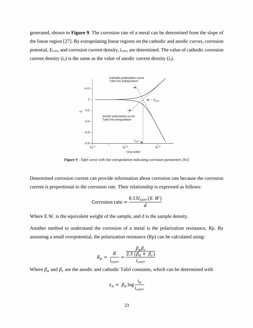
23
generated, shown in Figure 9. The corrosion rate of a metal can be determined from the slope of
the linear region [27]. By extrapolating linear regions on the cathodic and anodic curves, corrosion
potential, Ecorr, and corrosion current density, icorr, are determined. The value of cathodic corrosion
current density (ic) is the same as the value of anodic current density (ia).
Figure 9 - Tafel curve with line extrapolation indicating corrosion parameters [61]
Determined corrosion current can provide information about corrosion rate because the corrosion
current is proportional to the corrosion rate. Their relationship is expressed as follows:
Corrosion rate =0.13𝐼𝑐𝑜𝑟𝑟(𝐸. 𝑊)
𝑑
Where E.W. is the equivalent weight of the sample, and d is the sample density.
Another method to understand the corrosion of a metal is the polarization resistance, Rp. By
assuming a small overpotential, the polarization resistance (Rp) can be calculated using:
𝑅𝑝 = 𝐵
𝑖𝑐𝑜𝑟𝑟=
𝛽𝑎𝛽𝑐
2.3 (𝛽𝑎 + 𝛽𝑐)
𝑖𝑐𝑜𝑟𝑟
Where 𝛽𝑎 and 𝛽𝑐 are the anodic and cathodic Tafel constants, which can be determined with
𝜖𝑎 = 𝛽𝑎 log𝑖𝑎
𝑖𝑐𝑜𝑟𝑟

24
𝜖𝑐 = 𝛽𝑐 log𝑖𝑐
𝑖𝑐𝑜𝑟𝑟
Where 𝜖𝑎 and 𝜖𝑐 are the anodic and cathodic polarization/overvoltage, icorr is the corrosion current
density, and ia and ic are anodic and cathodic current density.
The overvoltage can be expressed as:
𝜖𝑐/𝑎 = 𝐸𝑐/𝑎 − 𝐸𝑐𝑜𝑟𝑟
Where Ecorr is the mixed potential, and Ec/a is applied potential.
By combining the two overpotential equations, Tafel constants can be determined. If there are
unknown corrosion parameters, then the slopes of the cathodic and anodic linear regions in the
Tafel plot can be used as 𝛽𝑎 and 𝛽𝑐, respectively. These values are then used to calculate Rp. If
the metal has high Rp, it is highly resistance to corrosion.
2.7.2 Galvanostatic Charge-Discharge
ReHABs with the synthesized anodes and the commercialized zinc foil are galvanostatically
cycled between 1.4 to 2.1V. Typical galvanostatic charge and discharge profiles are shown in
Figure 10a.
Figure 10 - (a) A typical galvanostatic charge and discharge profile of ReHAB operated at 4C
(b) cyclability and coulombic efficiency of ReHAB with undoped LiMn2O4 [3]
Both charge and discharge curves show two different plateaus, an indication of two-phase lithium
extraction and intercalation processes [3]. As the number of battery cycle increases, the

25
polarization of the battery also increases. This leads to the discharge capacity and coulombic
efficiency to decrease as shown in Figure 10b. After the cyclaiblity test, the capacity retention can
be calculated with the capacities from the first and the last cycle.

26
Chapter 3. Synthesis of Zinc via Electroplating with Additives
3.1 Introduction
Since the invention of rechargeable aqueous batteries, the studies of new materials for the
electrodes have been carried out. In this project, ReHAB was selected. ReHAB consists of lithium
manganese oxide (LiMn2O4) as the cathode active material. LiMn2O4 is a good candidate as a
cathode material in the aqueous batteries because tightly bounded lithium ions make LiMn2O4
stable in air and water [6]. Also, it shows a small volume variation between lithiated and non-
lithiated states [3]. As for the anode, zinc metal was selected because of its low redox potential,
good reversibility, high over-potential for hydrogen evolution in acidic environment, large specific
capacity, good corrosion resistance, and cost effectiveness [3, 14, 15].
Theoretically, an ideal performance is expected from ReHAB, but in reality, there are still some
rooms to improve. This project was focused on the modifications of the zinc anode. When zinc is
utilized in the aqueous batteries, a few problems associated with zinc metal arises. They are:, metal
corrosion, dendrite formation, and hydrogen gas (H2) evolution [5, 16]. In order to alleviate these
problems, many studies [17, 18, 21-23] have been conducted to mitigate the aforementioned
problems with zinc metal.
In this project, zinc was synthesized via electroplating with additives. 7 additives (4 organic and 3
inorganic additives) were selected to modify the structure of the zinc deposits. The performance
of the zinc with these additives were then analyzed via XRD, SEM, battery and corrosion tests.

27
3.2 Experimental Procedures
3.2.1 Battery Components
3.2.1 Cathode
The synthesis of the cathode was carried out as described: 86 wt.% analytical grade of LiMn2O4
(MTI Co.), 7 wt.% KS-6 graphite (Timcal), and 7 wt.% polyvinylidene fluoride (PVDF, Kynar,
HSV900) were mixed in n-methyl-2-pyrrolidone (NMP, Sigma-Aldrich Co., 99.5% purity) using
Planetary Centrifugal Mixer (AR-100, ThinkUSA) for 2 minutes. The mixed slurry was then casted
on a graphite foil (Alfa Aesar, 99.8%) and placed in 60°C vacuum chamber for 3 hours. The dried
slurry was cut in a circle with 12mm diameter.
3.2.2 Electrolyte
A mixture of zinc sulfate and lithium sulfate was used as the electrolyte. 1M zinc sulfate
heptahydrate (Alfa Aesar Co., 98%) and 2M lithium sulfate (Sigma, 98%) were dissolved in DI
water, and its pH was adjusted to 4 using sulfuric acid.
3.2.3 Separator
The separator used in the batteries was absorptive glass mat (AGM, NSG Corporation). It is highly
porous that it can absorb a large amount of electrolyte.
3.2.2 Anode Preparation
3.2.2.1 Electroplating Solution
The electroplating solution was prepared by dissolving 0.6M zinc sulfate (Alfa Aesar, 98%), 0.1M
ammonium sulfate (Sigma, 99%), and 100ppm of additive in Di-water. The selected additives were:
cetyl trimethylammonium bromide (CTAB, Signma, 98%), sodium dodecyle sulfate (SDS,
Signma, 99%), polyethylene glycol 8000 (PEG, Signma, MW 8000, 99%), thiourea (Alfa Aesar,
28
99%), indium (II) sulfate (Sigma, 99.99%), tin (IV) oxide (Sigma, 99.9%), and boric acid (Signma,
99.5%). Each of the additives was added to the electroplating bath individually.
3.2.2.2 Hull Cell
Hull cell experiment was carried out in a plastic Hull cell container as shown in Figure 6. The
consumable anode, in this case zinc foil, was placed on the left side of the container, and a cathode
on the right. As according to the theory, 267mL of the electroplating solution was used in each
experiment. Direct current (1A and 1.5A) was applied using BK Precision machine to the Hull cell
set-up for 10 minutes at room temperature. Then, the synthesized samples were dried overnight in
air.
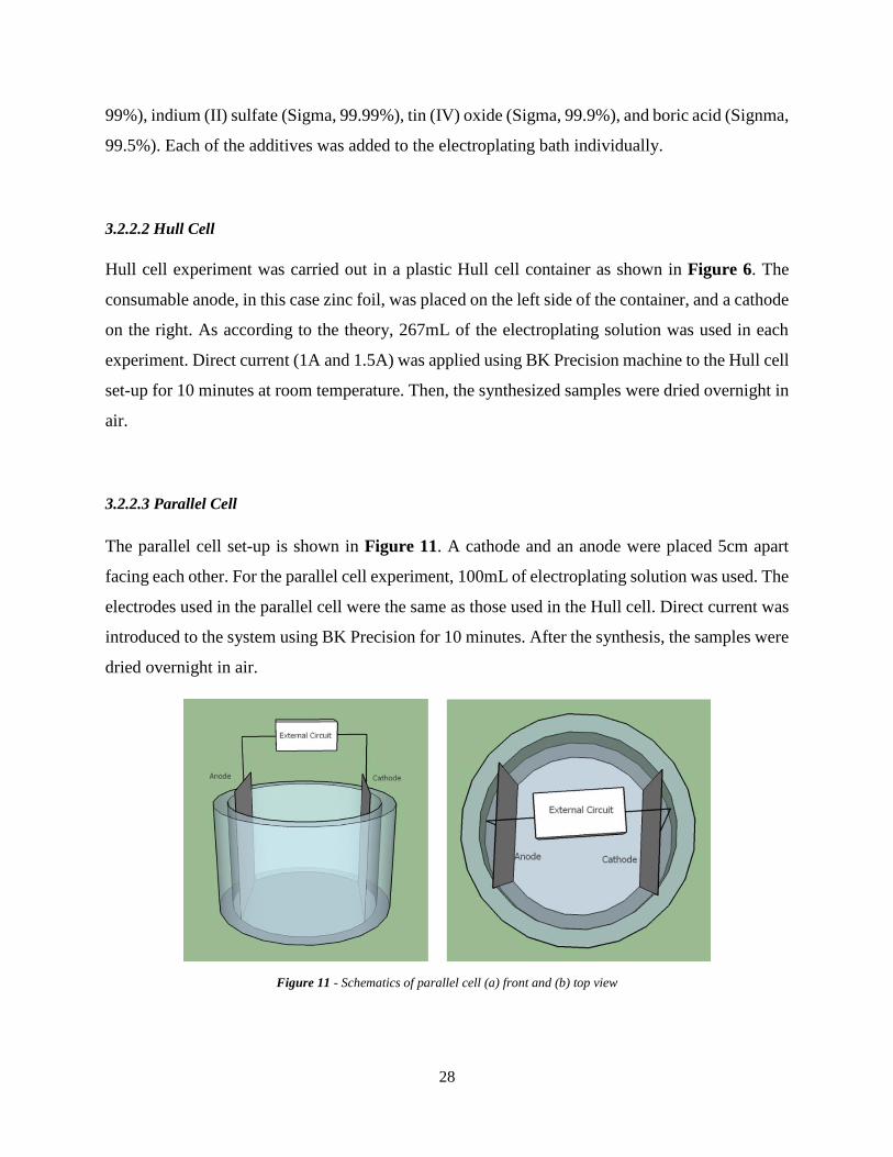
3.2.2.3 Parallel Cell
The parallel cell set-up is shown in Figure 11. A cathode and an anode were placed 5cm apart
facing each other. For the parallel cell experiment, 100mL of electroplating solution was used. The
electrodes used in the parallel cell were the same as those used in the Hull cell. Direct current was
introduced to the system using BK Precision for 10 minutes. After the synthesis, the samples were
dried overnight in air.
Figure 11 - Schematics of parallel cell (a) front and (b) top view

29
3.2.2.4 Substrates
Two different substrates were selected: graphite (Alfa Aesar, 99.8%) and brass foil. The graphite
foil was selected because a good battery performance was observed when it was used as the
substrate for the cathode in ReHAB. The brass foil was chosen as another type of substrates to
deposit zinc on. A good contact between the zinc deposits and the brass foil was assumed to be
made as brass contains zinc. This hypothesis was verified through experiments.
There was no treatment done on the graphite foil. As for the brass foil, the optimal brass treatment
was determined by comparing different treatment methods.
3.2.2.4.1 Brass Foil Treatment
In this project, four treatment methods were selected: no treatment, mechanical, chemical, and the
combination of mechanical and chemical methods. As for the mechanical treatment, the surface of
the brass foil was sanded using a sand paper. After the sanding, the brass was washed with DI
water to remove any residuals left on the surface.
As for the chemical treatment, it was carried out using nitric acid (HNO3). After the brass foil was
cut into an appropriate size, it was dipped into 25 vol. % HNO3 solution for 5 seconds, and
thoroughly washed with DI water. Then, it was dried in air.
After each treatment, the brass foil was used as the substrate to deposit zinc.
3.2.3 Characterization Technique Conditions
The crystallinity of the synthesized anode was analyzed with D8 Discover power x-ray diffraction
(XRD, Bruker Co., CuK∝ 1.5406Å , 40kV, and 40A). The samples were scanned (ex-situ) over 2
theta range 10 to 90° at the rate of 0.003 °min-1 with LynxEye detector. The XRD results were
analyzed with the Bruker XRD search match program EVATH.
The morphologies of the synthesized anodes were examined with field emission scanning electron
microscopy (FE-SEM, Carl Zeiss Ultra Plus Field Emission SME, Zeiss Co.), operated at 10kV.

30
The corrosion data of the as-prepared samples and the commercialized zinc was collected with
VMP3 potentiostat/galvanostat (Bio-Logic Science Instrument Co.). The corrosion current and
potential were measured in a three electrode cell system by applying linear polarization technique.
The working, counter, and reference electrodes were zinc, platinum, and Hg/Hg2SO4, respectively.
The electrode was scanned between -0.25V to 0.25V from its open circuit voltage (OCV) at the
rate of 0.166mV/s. The surface area of the tested electrode was ~1cm2. It was used to convert
corrosion current density (icorr) to corrosion current (Icorr).
The cycle life of the batteries with the synthesized and the commercialized anodes were tested in
coin cell type batteries. These batteries contained the cathode, electrolyte, anode, and the separator
as described in the above sections. The galvanostatic charge-discharge cycling of the batteries were
carried out at room temperature at 4C rate (1C = 120mAh/g) with NEWWARE battery tester [14]
(NEWWARE Battery Test System, Neware Co. Ltd., China). The battery was cycled between
1.4V to 2.1V.
The same battery tester was used to perform the float current test. For this test, two-electrode
SwagelockTH-type cells were used. The potential of the batteries were maintained at 2.1V for 7
days at room temperature, and the current necessary to maintain the potential was recorded.
3.3 Result and Discussion
3.3.1 Determining Zinc Electroplating Condition
Before the synthesis of zinc with the additives, the electroplating conditions to deposit the
minimum amount of zinc required to run ReHAB as the one with commercialized zinc foil
(Rotometals, thickness 0.2mm) were determined. Since there were two unknown variables – the
current density and the deposition time, two experiments were carried out. In the first experiment,
deposition time was fixed to find the optimal current density to synthesize zinc that can produce
good ReHAB performance as the one with the commercialized zinc; and in the second experiment,
the deposition time was varied by fixing the determined current density in the previous experiment
to investigate how deposition time affects the performance of ReHAB.

31
These experiments were done in the Hull cell set-up. Just to note that zinc deposition in this section
was carried out on the graphite foil substrate.
As shown in Table 1, the deposition time was fixed to 10 minutes for all the samples, and they
were deposited with different current densities (30, 50, and 80 mA/cm2). This experiment also
indicated what morphology of zinc would be suitable in ReHAB system because morphology of a
deposit changes with current density.
Table 1 - Summary of deposited samples with zinc deposition time and corresponding current densities
Sample # Deposition
Time (min)
Current Density
(mA/cm2)
1
10 min
30
2 50
3 80
After the electrodeposition of zinc, the samples were tested in ReHAB, and their results are shown
in Figure 12. The battery with the zinc electroplated with 30mA/cm2 showed fast capacity fading
in comparison to the ones with higher current densities and the commercialized zinc foil. The
batteries with 50 and 80 mA/cm2 showed comparable battery performance as the ones with the
commercialized zinc foil. Hence, it was enough to use 50mA/cm2 to electroplate zinc as the battery
with this anode could maintain high capacity as the commercialized zinc foil battery.

32
0 50 100 150 200 250 3000
10
20
30
40
50
60
70
80
90
100
110
Specific
Capacity (
mA
h/g
)
Cycle #
30mA/cm2
50mA/cm2
80mA/cm2
Commercial
Cyclability
Figure 12 - Cyclaiblity of ReHAB with synthesized zinc anodes electroplated at current densities
of 30, 50, 80 mA/cm2 for 10min and commercial zinc foil (Commercial)
The next experiment was to investigate how the performance of ReHAB would change with
deposition time. For this experiment, the current density was fixed at 50 mA/cm2 and the
deposition time was varied from 6 to 20 minutes.
Table 2 - Summary of the deposited samples with their zinc deposition time and corresponding current densities
Deposition Time (min) Current Density (mA/cm2)
6
50
8
10
15
20
Figure 13 is the cyclability of ReHAB with the zinc anodes electroplated for various deposition
time. When ReHAB employed the anodes electroplated for 6 and 8 minutes, the capacities of the
batteries were lower than the one with zinc electroplated for 10 min. When the zinc deposition
time was higher than 10 min, very similar battery performance was observed as the one

33
electroplated for 10 min. Hence, the current density of 50mA/cm2 and the deposition time of 10
min were selected as the electroplating conditions to synthesize zinc anodes.
0 50 100 150 200 250 3000
10
20
30
40
50
60
70
80
90
100
110
Sp
ecific
Dis
ch
arg
e C
ap
acity (
mA
h/g
)
Cycle #
6min
8 min
10min
15min
20min
Cyclability
Figure 13 - Cyclaiblity of ReHAB with synthesized zinc anodes electroplated at 50mA/cm2 for deposition time of 6, 8, 10, 15,
20min and commercialized zinc foil (Commercial)
3.3.2 Treatment of Brass Foil
Before using the brass foil as a substrate for the anode, the surface of the brass underwent three
different treatments. Firstly, two treatment methods were compared: mechanical and chemical
treatments. After the treatment, zinc ions were deposited on the treated surface of the brass foil.
The performance of ReHAB with these anodes is shown in Figure 14.

34
Figure 14 - Result of the discharge capacity retention and the cyclability plot from ReHAB with brass foil substrate exposed to
different treatments (Hull cell result)
When there was no treatment done on the brass foil, the lowest discharge capacity retention of 50%
was obtained at the 300th battery cycle. The highest capacity retention was found when the brass
foil was treated with nitric acid.
The capacity was well maintained when the brass foil was treated with nitric acid. This implies
that a good contact between the substrate and the electroplated zinc was achieved when the surface
was treated with acid. The mechanical sanding showed better battery performance than the one
without any treatments, but its performance was worse than the one with chemically treated brass
foil substrate. At the 300th cycle, the average capacity retention of ReHAB with the mechanical
sanding was smaller than that with the acid-treated brass foil. Also, a large error bar indicated
polishing with the sandpaper is unreliable. Therefore, the treatment with nitric acid was preferred
and selected.
In the next experiment, the effect of combining the mechanical and chemical methods was
investigated as T.M.H Saber et al.[50] achieved the optimal results (oxide-free and scratch-free
brass surface) by combining the two methods. The performance of ReHAB with this substrate is
summarized in Figure 15.

35
Figure 15 - Result of the discharge capacity retention and the cyclability plots from ReHAB with brass foil substrate exposed to
different treatments (Parallel cell result)
The effect of combining the mechanical and chemical treatments, which is labelled as ‘Mech-acid,’
is shown in Figure 15. As shown in the capacity retention and cyclability plots, the performance
of ReHAB with the brass treated with both methods generated similar performance as the one with
the brass foil treated with only acid. Hence, modifying the surface of the brass foil with only acid
was sufficient to produce good ReHAB performance. Therefore, only nitric acid was used to treat
the brass foil to enhance the contact (or reduce the resistance) between the brass foil and the
deposits.
3.3.3 Comparison of Two Substrates – Graphite and Brass Foils
The comparison of two substrates (graphite and brass foil) was carried out in this section. In the
beginning of the project, the graphite foil was primarily used, but its flexible property led the
graphite foil to be easily torn. Thus, the brass foil was chosen to replace the graphite foil as the
substrate for zinc ion deposition.
In order to identify whether the performance of ReHAB with the brass foil was compatible as that
with the graphite foil, ReHAB was assembled with these substrates. The performance of ReHAB
with the zinc anode electroplated on the graphite and the acid-treated brass foil is shown in Figure

36
16. ReHAB with brass foil is labelled as ‘Acid Treated,’ and the battery with graphite foil as
‘Graphite Foil.’
Figure 16 - Result of the discharge capacity retention and the cyclability plots from ReHAB with graphite and brass foil as
anode substrates (Hull cell result)
From the results shown above, about 17% higher capacity retention was observed with ReHAB
with the acid treated brass foil than that with the graphite substrate at the end of 300th cycle. In
other words, the battery capacity was well maintained when brass foil was used as the substrate
for the anode. Thus, only brass foil was used as the substrate (in electroplating) and the current
collector (in ReHAB).
3.3.4 Optimal Additive Concentrations
The amount of additive used during electroplating influences the property of the deposits, and thus,
many studies [62-66] have been carried out to determine the optimal additive concentrations. In
this section, the optimal additive concentrations were identified.
In order to compare the effect of each additive fairly, the optimal concentration of each additive
was required. In this project, however, one of the additives was randomly selected and its optimal
concentration was assumed to be equal to the optimal concentration of the rest of the additives due

37
to the time constraint. The randomly selected additive was boric acid, and its optimal concentration
was determined in this section.
For identifying its optimal concentration, four different concentrations of boric acid were selected:
0, 50, 100, and 500ppm.
Figure 17 - SEM images of zinc deposits with 0 (no additive), 50, 100, and 500ppm
of boric acid in electroplating bath (magnification 1k)
With different concentrations of boric acid, different morphologies were obtained. The SEM
images indicated that in general, stacks of irregular platelets were generated as shown in Figure
17. Similar structure to these SEM images was also seen in C. Hu et al. [37]. This kind of structure
is obtained when high current density is applied to deposit zinc ions [67]. With smaller current
density, the morphology of the zinc deposits created in a zinc sulfate solution would become
regular hexagonal crystalline structure [53, 67].
When there was no additive used, the zinc deposits were coarse and irregular. As the concentration
of boric acid increased, the size of the deposits became smaller and more uniform. From the SEM
images, 100 and 500ppm of boric acid produced uniformly distributed zinc deposits.

38
0 PPM 50 PPM 100 PPM 500 PPM0.0
0.2
0.4
0.6
0.8
1.0
1.2
Flo
at C
urr
ent per
gra
m o
f LM
O (
mA
/g)
Float Current
Figure 18 - Float current of ReHAB with electroplated anode with 0, 50, 100, and 500ppm of boric acid in electroplating bath
The float current results are plotted in Figure 18. The battery with the anode electroplated without
the additive (labelled as ‘0 ppm’) presented the highest float current. When higher concentration
of boric acid was employed to synthesize the zinc deposits, smaller float current was obtained. In
other words, the zinc electroplated with higher concentrations of boric acid reduced the side
reactions occurring in the batteries when they are not in use. When the concentration of boric acid
exceeded 100ppm, however, the amount of float current remained about the same.
Table 3 - Summary of corrosion potential and current of the electroplated anode
with 0, 50, 100, and 500ppm of boric acid in electroplating bath
Corrosion
Potential (mV)
Corrosion
Current (uA)
0 PPM -1429 ± 5 1136 ± 82
50 PPM -1428 ± 7 133 ± 14
100 PPM -1419 ± 9 156 ± 13
500 PPM -1422 ± 8 160 ± 23
Table 3 presents the corrosion potentials and currents of the synthesized zinc obtained by
analyzing their Tafel plots. From the results, the zinc deposited without additives showed the
highest corrosion current. This may be due to the modified crystalline structure using boric acid

39
during the zinc deposition as shown in Figure 19. When there was no additive used during
electroplating zinc, the strong peak of (103) was shown. With the presence of boric acid (100ppm),
the crystalline orientation was favoured in (002). Hence, the corrosion rate may be increased if a
sample consists of a strong peak of (103).
Figure 19 - XRD of zinc electroplated (A) without additives and (B) with 100ppm of boric acid
The values of the corrosion currents were similar between the zinc electroplated with any
concentrations of boric acid, but the values slightly increased with the concentration of boric acid.
In other words, overuse of boric acid was not preferred.
Based on these results, 100 ppm of boric acid was determined to be the optimal concentrations as
the zinc produced with this concentration not only showed the uniform deposits, but also reduced
the float current and corrosion rate. The anode produced with 500 ppm of boric acid also generated
similar results as that with 100 ppm. Hence, there was no need to use higher concentration of boric
acid as smaller dose produced about the same results. Therefore, 100 ppm was chosen as the
optimal concentration for boric acid, and it was assumed to be the optimal concentrations for the
other additives as well.

40
3.3.5 Effect of Organic Additives
In this project, four organic additives were selected: cetyl trimethylammonium bromide (CTAB),
sodium dodecyle sulfate (SDS), polyethylene glycol 8000 (PEG), and thiourea.
Many literatures investigated the effect of the selected additives on the synthesis of zinc via
electroplating:
1. CTAB: reduction in grain size [53], corrosion inhibitor [68]
2. SDS: corrosion inhibitor [69], hydrogen evolution inhibitor during electroplating [54]
3. PEG: hydrogen adsorption inhibitor, enhancement of current efficiency during
electroplating [70], corrosion inhibitor [71]
4. Thiourea: hydrogen evolution inhibitor during electroplating [70], corrosion inhibitor [72]
In order to analyze the effect of the zinc electroplated with these additives, the studies on the zinc
electroplated in additive-free solution (Zn-No) and the commercialized zinc foil were also
conducted.
3.3.5.1 XRD Result
The XRD results of the synthesized zinc with the organic additives and the commercialized zinc
are shown in Figure 20 and Figure 22. The XRD of the zinc electroplated without additives is
presented in Figure 21 to show how additives modified the crystalline structure of zinc.
According to the XRD of the synthesized and the commercialized zinc, the zinc crystals were
growing in various orientations. As for the commercialized zinc foil, the highest intensity peak
was found at 42°, indicating zinc growth mostly in (101) orientation. The other significant planes
were (102), (103), (100), (002), (110), (112), (200), and (201). These peaks were also seen in
literature [53, 68].
The morphology of the commercialized zinc is shown in Figure 20. Flat and smooth surface with
defects (holes) were observed. These holes may be produced during its synthesis. The performance
of the commercial zinc will be discussed in the later part of the thesis.

41
10 20 30 40 50 60 70 80 90
(201)
(200)(1
12)
(110)
(103)
(102)
(101)
(002)
Inte
nsity (
a.u
.)
2 Theta
XRD of Commercialized Zinc Foil
(100)
Figure 20 - XRD and SEM images of the commerciali zinc foil
Figure 21 - XRD of the electroplated zinc without any additives at low and high current densities.
For lower current density XRD was obtained from Hull cell, and the high current density from parallel cell

42
10 20 30 40 50 60 70 80 90
*
(002)
(102)
(002)
(102)
(102)
(103)
(103)
(103)
(101)
(101)
Thiourea
Inte
nsity (
a.u
.)
2 Theta
CTAB
SDS
PEG
(100)
(101)
(110)
*
* Brass Substrate
XRD (Organic Additive)
Figure 22 - XRD results of the zinc anode electroplated with organic additives
When no additive was used during the zinc deposition with low current density, the preferred
orientation was (002), which was consistent with literature [53, 68]. With higher current density
(experiment done in the parallel cell), the growth orientation was mostly directed in (103). This
indicates that current density plays an essential role in metal plating. Between the two samples,
the one electroplated with higher current density was used to compare with the zinc electroplated
with the organic additives.
The XRD of the electroplated zinc with the organic additives, shown in Figure 22, consisted of
the same zinc peak locations as the commercialized zinc foil and literature [53, 65]. The intensities
of the peaks, however, were not the same, indicating different crystalline growth. It is clear that
each of the organic additives produced a unique crystalline structure as the peak intensities were
different. The changes in the crystallinity of the sample suggests that during electroplating, the
additives altered the surface energy because crystals tend to grow in the direction with the lowest
surface energy [53]. Not only that, but also the experimental procedure may be another factor
contributing to the variations in XRD peak intensity [53].

43
The usage of CTAB, SDS and thiourea during the zinc deposition (Zn-CTAB, Zn-SDS, Zn-TU)
led a strong orientation at (101), which was also seen in literature [62, 64, 73]. The dominant (101)
peak was also found in the XRD of the commercialized zinc foil. The changes in the preferential
growth from (103) to (101) suggests that CTAB, SDS, and thiourea modified the electroplated
anode to become more like the commercialized zinc foil. Also, Machinnon et al. [74] explained
that having the preferential growth of zinc in (101) implies that high current efficiency was
achieved when zinc ions were deposited. This finding is in accordance with D.J. Mackinnon et al.
[75]‘s data of high zinc deposition efficiency obtained with organic additives.
As for the zinc electroplated with PEG (Zn-PEG), zinc crystalline was mostly oriented in (103).
Although the preferential orientation of Zn-PEG was the same as that of Zn-No, PEG significantly
reduced the peak representative in (101) planes, which was the second dominant peak of Zn-No.
According to D.J. Mackinnon et al. [74], the preferred orientation of (103) represents that zinc was
deposited with low current efficiency. K. Song et al. [70] also found that the addition of
polyethylene glycol (MW = 2000) reduced zinc deposition efficiency.
Zn-CTAB showed the second highest peak intensity in (100), whereas the commercialized zinc
showed in (103). As for Zn-SDS anode, SDS relatively enhanced the growth of (002) and (102)
planes, and inhibited (100) plane. The XRD of Zn-TU indicated that some of planes were oriented
in (102) and (103), but their intensities were much lower than (101) – in other words, thiourea
enhanced the zinc growth only in one orientation. As for Zn-PEG, it also showed zinc plane
orientation in (002) and (102).

44
3.3.5.2 SEM Result
Figure 23 - SEM images of synthesized anode with organic additives (magnification 5k)
Figure 23 shows the SEM images of the electroplated zinc with the organic additives. Although
the commercialized zinc foil and Zn-CTAB, Zn-SDS, and Zn-TU showed the highest (101) peak,
the morphologies of the zinc were all different, which indicates that the contribution from other
peaks were also important.
The morphology of Zn-CTAB was porous needle-like crystals with uniform size distributed evenly.
This kind of structure was obtained due to a strong blocking effect of CTAB that increased the
competition between the nucleation and crystal growth [53].
As for Zn-SDS and Zn-PEG, their morphologies were regular and uniformly distributed. The zinc
deposits were growing perpendicular to the substrate and in various directions. This kind of
structure is obtained when the active site and nucleation rate were reduced as additives adsorbed
onto the surface of a substrate [53, 76].

45
As for Zn-TU, the deposit was also uniform and regular, but was not compact as Zn-SDS and Zn-
PEG. Some of the area were empty possibility due to the hydrogen gas presented on the surface,
blocking the zinc deposition.
3.3.5.3 Float Current
No Additive CTAB SDS PEG Thiourea Commercial0.0
0.2
0.4
0.6
0.8
1.0
1.2
1.4
Flo
at C
urr
ent per
gra
m (
mA
/g)
Float Current (Organic Additive)
Figure 24 - Float current of ReHAB with zinc deposited with/without organic additives and commercialized zinc foil
Figure 24 is the plot of float current of ReHAB with the synthesized zinc with and without the
organic additives and the commercialized zinc foil (labelled as ‘Commercial’). The lowest and the
highest float currents were obtained with Zn-SDS and Zn-TU, respectively. Hence, when zinc was
synthesized in the bath containing SDS, Zn-SDS was able to reduce the self-discharge of ReHAB.
In other words, the side reactions, or hydrogen evolution, were slowed down with Zn-SDS anode.
The next lowest float current was observed from ReHAB with Zn-PEG anode.
ReHAB with Zn-CTAB produced higher float current than that with Zn-PEG due to higher surface
area; but it was lower than that with Zn-TU. The float current from ReHAB with Zn-TU anode
was about the same as that with the commercialized zinc foil. Moreover, the float current of the
battery with Zn-No was similar to that with Zn-CTAB and Zn-TU as the error bars overlap each
other. Hence, the usage of CTAB and thiourea to modify the structure of zinc was not as effective
as SDS and PEG in reducing the self-discharge of ReHAB.
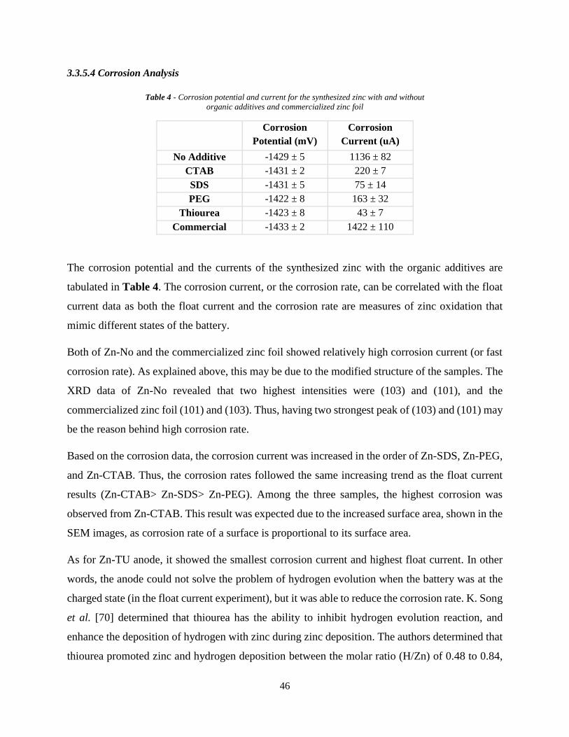
46
3.3.5.4 Corrosion Analysis
Table 4 - Corrosion potential and current for the synthesized zinc with and without
organic additives and commercialized zinc foil
Corrosion
Potential (mV)
Corrosion
Current (uA)
No Additive -1429 ± 5 1136 ± 82
CTAB -1431 ± 2 220 ± 7
SDS -1431 ± 5 75 ± 14
PEG -1422 ± 8 163 ± 32
Thiourea -1423 ± 8 43 ± 7
Commercial -1433 ± 2 1422 ± 110
The corrosion potential and the currents of the synthesized zinc with the organic additives are
tabulated in Table 4. The corrosion current, or the corrosion rate, can be correlated with the float
current data as both the float current and the corrosion rate are measures of zinc oxidation that
mimic different states of the battery.
Both of Zn-No and the commercialized zinc foil showed relatively high corrosion current (or fast
corrosion rate). As explained above, this may be due to the modified structure of the samples. The
XRD data of Zn-No revealed that two highest intensities were (103) and (101), and the
commercialized zinc foil (101) and (103). Thus, having two strongest peak of (103) and (101) may
be the reason behind high corrosion rate.
Based on the corrosion data, the corrosion current was increased in the order of Zn-SDS, Zn-PEG,
and Zn-CTAB. Thus, the corrosion rates followed the same increasing trend as the float current
results (Zn-CTAB> Zn-SDS> Zn-PEG). Among the three samples, the highest corrosion was
observed from Zn-CTAB. This result was expected due to the increased surface area, shown in the
SEM images, as corrosion rate of a surface is proportional to its surface area.
As for Zn-TU anode, it showed the smallest corrosion current and highest float current. In other
words, the anode could not solve the problem of hydrogen evolution when the battery was at the
charged state (in the float current experiment), but it was able to reduce the corrosion rate. K. Song
et al. [70] determined that thiourea has the ability to inhibit hydrogen evolution reaction, and
enhance the deposition of hydrogen with zinc during zinc deposition. The authors determined that
thiourea promoted zinc and hydrogen deposition between the molar ratio (H/Zn) of 0.48 to 0.84,

47
depending on the concentration of thiourea added to the electroplating bath [70]. According to
their theory, the absorbed hydrogen either desorbed back by forming hydrogen gas or adsorbed
into the deposits. Therefore, small corrosion rate of Zn-TU may be explained with smaller amount
of zinc deposited in comparison to other samples, and high float current with higher amount of
adsorbed hydrogen in the deposits desorbing out and forming hydrogen gas inside ReHAB.
3.3.5.5 Battery Performance
Figure 25 - Retention and cyclability of the ReHAB with zinc anode with organic additives and commercialized zinc foil
After the above experiments, ReHAB were assembled with the synthesized zinc, and their
performance is summarized in Figure 25. All the batteries, except for the ones with Zn-CTAB,
showed improved cyclaiblity. The average capacity retentions of 79, 76, 80, and 71% were
obtained at the 1000th cycle from the batteries with Zn-SDS, Zn-PEG, Zn-TU, and commercialized
zinc foil, respectively. Although the initial capacities of ReHAB with the electroplated zinc with
the additives were lower than those with the commercialized zinc, the capacities of the batteries
were more stable throughout the cycles.
As for the batteries with Zn-CTAB, a sudden capacity drop occurred after running about 350 cycles,
which may be the result of the dendrites. The high surface area of Zn-CTAB possibly increased

48
the chance of the dendrites to grow, and led to the failure of the batteries. At the 1000th cycle, only
12% of original capacity was remained.
Therefore, except for Zn-CTAB, all the electroplated samples were able to solve the problems
associated with the commercialised zinc foil by reducing the float current and the corrosion rate.
Among the organic additives, SDS was the most preferred as it reduced the side reactions (float
current and corrosion) and the capacity of the battery was well maintained until the 1000th cycle.
3.3.6 Effect of Inorganic Additives
Not many studies have been done to investigate the effect of inorganic additives during the
synthesis of zinc deposits via electroplating. Hence, in this project, three inorganic additives were
selected to learn how they affect on the zinc deposits. The selected inorganic additives were:
indium sulfate, tin oxide, and boric acid.
Indium sulfate and tin oxide are usually used as the additives in the zinc powder anode, and their
effects are determined to be:
1. Indium sulfate: inhibition of dendrite formation[77], improvement in cycle life [77]
2. Tin Oxide: suppression of hydrogen evolution [78], and stability of the electrode [79]
Unlike the above two, some of the studied presented the effects of boric acid during electroplating
metal ions. Boric acid are usually used as a buffer reagent to keep the pH of the electroplating
solution relatively constant. It is also used to act as a catalyst, suppress hydrogen evolution,
accelerate the growth rate, and reduce the passive film during nickel electrodeposition [80].

49
3.3.6.1 XRD Result
10 20 30 40 50 60 70 80 90
*
(102)
(103)
(002)
(002)
(102)
(103)
XRD (Inorganic Additives)
Tin Oxide
Inte
nsity (
a.u
.)
2 Theta
Indium Sulfate
Boric Acid
(101)
(102) (1
03)
*
* Brass Substrate
Figure 26 - XRD results of the zinc anode electroplated with inorganic additives
The crystalline structures of the zinc deposited with the inorganic additives are shown in Figure
26. From Figure 26, it can be seen that the samples electroplated with additives showed the same
peak position as the zinc deposited without any additives (Zn-No) and the commercialized zinc
foil. The intensities of the peak, however, were not the same as the reference zinc samples (Zn-No
and the commercialized zinc foil).
Based on the XRD data, it can be seen that unlike the organic additives, it was not clear how the
inorganic additives were modifying the zinc crystallinity. When indium sulfate, tin oxide, and
boric acid were used to deposit zinc ions (Zn-In, Zn-TO, Zn-BA), the preferred growth orientation
for Zn-In was (103), Zn-TO (002) and (103), and Zn-BA (002). Some of the data are in accordance
with literature [75]. The variation in the peak intensities between literature and the obtained data
may be due to the different experimental procedures [53]. As for indium sulfate, even though it
promoted (103) peaks as Zn-No anode, the intensities of other peaks were different from those
seen in Zn-No.

50
D.J. Mackinnon et al. [74] explained that high intensities in (002) and/or (103) planes represent
the decrease in zinc deposition current efficiency. Since all samples showed dominant (002) and/or
(103) planes, it can be assumed that significant amount of side reaction (hydrogen gas) occurred
during the zinc deposition.
One of the interesting results is that the relative intensities of (101), (102), and (103) peaks from
the three samples displayed the same trend. For instance, the XRD peaks of Zn-In presented the
smallest intensity at (101) and the highest intensity at (103) among three peaks. This trend was
also seen in the XRD of Zn-TO and Zn-BA. If there were no changes in (002) peak intensity, three
electroplated zinc would be identical to one another. As a result, (002) planes could be one of the
factors affecting the behaviour of the synthesized zinc with the inorganic additives. The smallest
intensity of (002) was found in Zn-In, and the highest in Zn-BA.
3.3.6.2 SEM Result
Figure 27 - SEM images of synthesized anode with inorganic additives (magnification 2k)
The morphologies of the zinc electroplated with the inorganic additives are shown in Figure 27.
From Zn-In SEM images, a thick chunk of zinc was deposited irregularly. Each of the chunk

51
consisted of many layers of zinc. On top of the surface, thin fiber-like deposits were observed,
which was also determined to be zinc based on the EDX analysis. This kind of morphology may
be created when additives promoted (103), (102), and (101) planes and inhibited (002) planes.
As for Zn-TO and Zn-BA anodes, the morphology of the samples were similar to that of Zn-SDS
and Zn-PEG. As shown in Figure 27, stacks of poorly defined hexagonal platelets of zinc were
observed. A difference between the two samples is that the growth of zinc in Zn-TO was more
organized than that in Zn-BA, because the platelets were more uniform and stacked well in Zn-TO
than those in Zn-BA. More organized structure may be achieved when the intensity of (002) plane
is equal to that of (103) planes (Zn-TO deposits). If the intensity of (002) planes is higher than that
of (103), the size of the deposits may start to show inconsistency.
3.3.6.3 Float Current
No Additive Indium Sulfate Tin Oxide Boric Acid Commercial0.0
0.2
0.4
0.6
0.8
1.0
1.2
1.4
Flo
at C
urr
ent
pe
r g
ram
(m
A/g
)
Float Current (Inorganic Additive)
Figure 28 - Float current of ReHAB with zinc deposited with inorganic additives and commercialized zinc foil
The float current results are shown in Figure 28. The average float currents for ReHAB with Zn-
In, Zn-TO, and Zn-BA were about twice smaller than that with Zn-No (‘No Additive’) and the
commercialized zinc foil (‘Commercial’). This indicates that if the batteries were not in use, the
amount of side reactions could be reduced by the employment of Zn-In, Zn-TO, and Zn-BA. Hence,
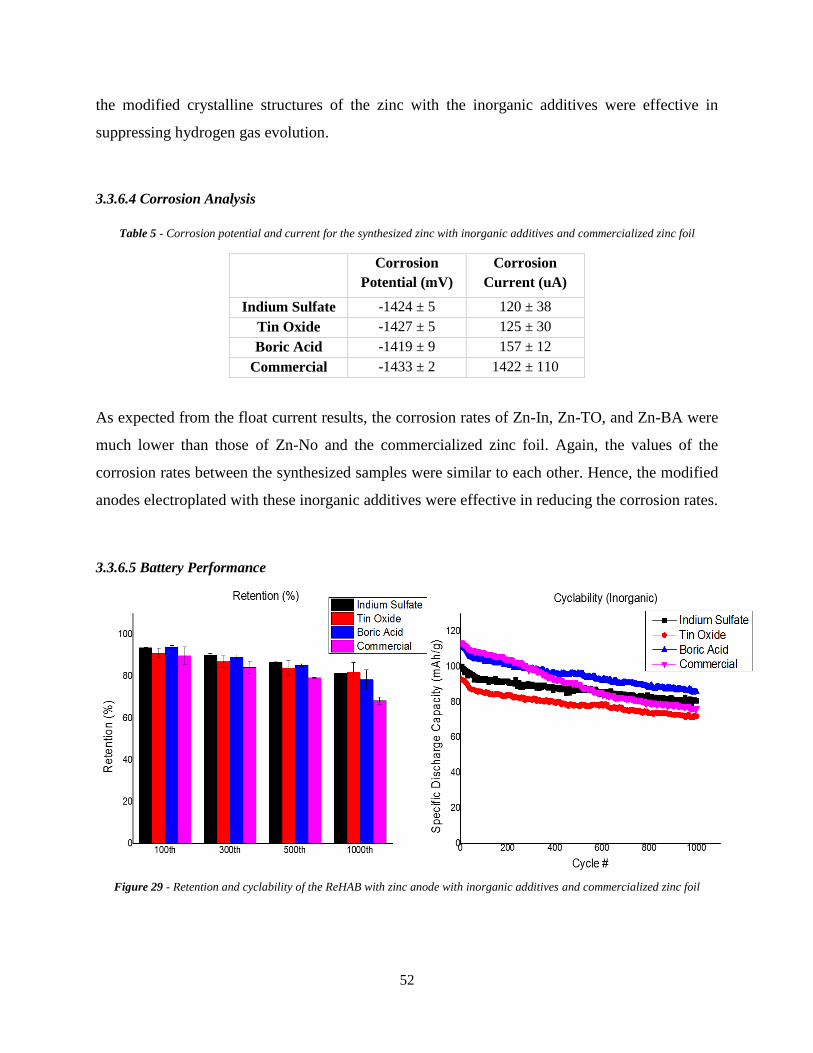
52
the modified crystalline structures of the zinc with the inorganic additives were effective in
suppressing hydrogen gas evolution.
3.3.6.4 Corrosion Analysis
Table 5 - Corrosion potential and current for the synthesized zinc with inorganic additives and commercialized zinc foil
Corrosion
Potential (mV)
Corrosion
Current (uA)
Indium Sulfate -1424 ± 5 120 ± 38
Tin Oxide -1427 ± 5 125 ± 30
Boric Acid -1419 ± 9 157 ± 12
Commercial -1433 ± 2 1422 ± 110
As expected from the float current results, the corrosion rates of Zn-In, Zn-TO, and Zn-BA were
much lower than those of Zn-No and the commercialized zinc foil. Again, the values of the
corrosion rates between the synthesized samples were similar to each other. Hence, the modified
anodes electroplated with these inorganic additives were effective in reducing the corrosion rates.
3.3.6.5 Battery Performance
Figure 29 - Retention and cyclability of the ReHAB with zinc anode with inorganic additives and commercialized zinc foil

53
The performance of the synthesized zinc with the inorganic additives is shown in Figure 29.
Similar to the batteries with zinc-organic additive anodes, better performance was observed with
the ReHAB with Zn-In, Zn-TO, and Zn-BA than that with the commercialized zinc foil. At the
end of 1000th cycle, the average capacity retention of 75, 82, and 78% were obtained from Zn-In,
Zn-TO, and Zn-BA batteries, respectively. The batteries with Zn-In and Zn-TO showed good
performance, but their initial capacities were lower than those with the commercialized zinc foil.
The initial capacity of ReHAB with Zn-BA, on the other hand, was as high as the one with the
commercialized zinc foil.

54
3.4 Conclusion
The current commercialized zinc foil raises a few problems in aqueous batteries, such as corrosion
dendrite formation, and hydrogen evolution. Hence, the objective of the project was to minimize
these problems by introducing a novel zinc anode synthesized by electroplating with additives.
Before the synthesis of the zinc anode with the additives, the electroplating condition was
determined to deposit the minimum amount of zinc that can function well as the commercialized
zinc in ReHAB. Based on the experiments, the current density of 50mA/cm2 and the deposition
time of 10min were selected to produce zinc anodes with 100ppm of organic and inorganic
additives. The zinc ions were deposited on a brass foil, treated with 25 vol. % nitric acid, as it
provided a good contact between the deposits and the brass foil.
All of the anodes synthesized with additives solved the problems associated with the current zinc
foil in ReHAB. When the zinc was deposited without any additives, the preferred orientation was
(103). By employing CTAB, SDS, and thiourea, the plane growth changed from (103) to (101).
Among the organic additives, Zn-SDS showed the lowest float current – in other words, it was
able to hinder the side reactions most effectively. All of the zinc showed smaller corrosion rates
than Zn-No and the commercialized zinc. When these anodes were used in ReHAB, 79, 76, and
80 % of the capacities retained after 1000th cycle with Zn-SDS, Zn-PEG, and Zn-TU, respectively.
These values were much higher than that of the commercialized zinc (capacity retention at the
1000th cycle was 71%).
As for the inorganic additives, the XRD results indicated that the zinc deposition was carried out
with low current efficiency as (002) and/or (103) peaks were dominant in all three samples. There
was, however, no quantitative results to distinguish which of the additives generated more side
reactions (or hydrogen evolution) during the zinc deposition. From the float current and corrosion
results, all of the zinc anodes with the inorganic additives reduced the side reactions. When these
anodes were utilized in ReHAB, 75, 82, and 78% of capacity were remained in Zn-In, Zn-TO, and
Zn-BA batteries, respectively, after running 1000 cycles.
Therefore, both the organic and inorganic additives were able to solve the problems ReHAB
currently faces. Despite similar performances in the float current, corrosion and the cyclaiblity
tests, the organic additives may be preferred over the inorganic due to their differences in XRD

55
results: according to literatures, higher zinc deposition current efficiency was achieved with the
organic additives. Therefore, among the four organic additives, SDS seemed the most effective
additive to synthesize the 2nd generation zinc anode for ReHAB.

56
Chapter 4. Future Work
1. Measure voltammetry of the zinc electroplated with additives
Cyclic voltammetry can provide detailed information on how the electroplated
anodes behave during a deposition and dissolution processes as in a battery. Hence, the
behaviour of the modified zinc can be explained in detail.
2. Measure hydrogen gas generated from ReHAB
The amount of hydrogen gas generated with the battery in operation can be another
evidence to indicate how effective the synthesized zinc anodes are in actual battery system.
3. Characterize the anodes after operation
The analyses of the used anodes in the ReHAB with XRD and SEM may explain
how these synthesized anodes were able to maintain high battery capacities.
4. Measure current efficiency during zinc deposition process
The electroplated zinc with the organic and inorganic additives did improve the
current issues with the commercialized zinc by reducing the corrosion rate and float current,
and enhancing the battery performance., Although the XRD data may indicate high or low
current efficiency of the zinc deposition according to literature, a direct measurement of
the current efficiency will provide more clear data on how efficient these additives are
during zinc deposition.
5. Combine additives during zinc deposition to obtain synergetic effects on the deposits
K.O. Nayana et al. [81] studied the effect of CTAB and ethyl vanillin (EV) during
zinc deposition. The authors determined that the deposits obtained in the bath containing
CTAB and EV was bright and smooth. The grain size of the deposit was also affected. By
mixing both additives together, the advantages of each additive were observed. If CTAB
and EV were employed individually, the size of the grain was about 70nm. When the
mixture of two was used, the grain size reduced to 49nm [81]. By reducing the grain size,
brighter deposit was obtained.

57
References
[1] S. Shafiee and E. Topal, "When will fossil fuel reserves be diminished?," Energy Policy,
vol. 37, pp. 181-189, 2009.
[2] J. M. Tarascon and M. Armand, "Issues and challenges facing rechargeable lithium
batteries," Nature, vol. 414, pp. 359 - 367, 2001.
[3] J. Yan, J. Wang, H. Liu, Z. Bakenov, D. Gosselink, and P. Chen, "Rechargeable hybrid
aqueous batteries," Journal of Power Sources, vol. 216, pp. 222-226, 2012.
[4] V. S. Bagotsky, A. M. Skundin, and Y. M. Volfkovich, Electrochemical Power Sources:
Batteries, Fuel Cells, and Supercapacitors. New Jersey: John Wiley & Sons, Inc., 2015.
[5] T. K. A. Hoang, T. N. L. Doan, K. E. K. Sun, and P. Chen, "Corrosion Chemistry and
Protection of Zinc & Zinc Alloys by Polymer-containing Materials for Potential Use in
Rechargeable Aqueous Batteries," Royal Society of Chemistry, vol. 5, pp. 41677 - 41691,
2015.
[6] W. Li, W. R. McKinnon, and J. R. Dahn, "Lithium Intercalation from Aqueous
Solutions," J. Electrochem. Soc., vol. 141, 1994.
[7] N. Alias and A. A. Mohamad, "Advances of aqueous rechargeable lithium-ion battery: A
review," Journal of Power Sources, vol. 274, pp. 237-251, 2015.
[8] W. Li and J. R. Dahn, "Lithium-Ion cells with aqueous batteries," Journal of
Electrochemical Society vol. 142, pp. 1742 - 1746, 1995.
[9] G. J. Wang, H. P. Zhang, L. J. Fu, B. Wang, and Y. P. Wu, "Aqueous rechargeable
lithium battery (ARLB) based on LiV3O8 and LiMn2O4 with good cycling
performance," Electrochemistry Communications, vol. 9, pp. 1873 - 1876, 2007.
[10] J.-Y. Luo, W.-J. Cui, P. He, and Y.-Y. Xia, "Raising the cycling stability of aqueous
lithium-ion batteries by eliminating oxygen in the electorlyte," Nature Chemistry, vol. 2,
pp. 760 - 765, 2010.
[11] J.-S. Lee, S. Tai Kim, R. Cao, N.-S. Choi, M. Liu, K. T. Lee, and J. Cho, "Metal-Air
Batteries with High Energy Density: Li-Air versus Zn-Air," Advanced Energy Materials,
vol. 1, pp. 34-50, 2011.
[12] D. Peramunage, R. Dilon, and S. Licht, "Investigation of a novel aqueous aluminum
sulfur battery," Journal of Power Sources, vol. 45, pp. 311 - 323, 1993.
[13] B. T. Hang, T. Watanabe, M. Eashira, S. Okada, J.-i. Yamaki, S. Hata, S.-H. Yoon, and I.
Mochida, "The electrochemical properties of Fe2O3-loaded carbon electrodes for iron–
air battery anodes," Journal of Power Sources, vol. 150, pp. 261-271, 2005.
[14] M. Hilder, B. Winther-Jensen, and N. B. Clark, "The effect of binder and electrolyte on
the performance of thin zinc-air battery," Electrochimica Acta, vol. 69, pp. 308-314,
2012.
[15] A. Ait Aghzzaf, B. Rhouta, E. Rocca, A. Khalil, and J. Steinmetz, "Corrosion inhibition
of zinc by calcium exchanged beidellite clay mineral: A new smart corrosion inhibitor,"
Corrosion Science, vol. 80, pp. 46 - 52, 2013.
[16] L. Zhu and H. Zhang, "A novel method for the modification of zinc powder by ultrasonic
impregnation in cerium nitrate solution," Ultrason Sonochem, vol. 15, pp. 393-401, Apr
2008.
[17] A. Renuka, A. Veluchamy, N. Venkatakrishnan, S. Nathira Begum, V. R. Chidambaram,
and R. Sabapathi, "Improved cycle life performance of Zn/NiOOH cells using a

58
stabilized zinc electrode," Journal of Applied Electrochemistriy, vol. 22, pp. 182 - 184,
1992.
[18] J. Kan, H. Xue, and S. Mu, "Effect of inhibitors on Zn-dendrite formation for zinc-
polyaniline secondary battery," Journal of Power Sources, vol. 74, pp. 113 - 116, 1998.
[19] D. Kalpana, K. S. Omkumar, S. S. Kumar, and N. G. Renganathan, "A novel high power
symmetric ZnO/carbon aerogel composite electrode for electrochemical supercapacitor,"
Electrochimica Acta, vol. 52, pp. 1309-1315, 2006.
[20] A. B. Company. (2014, September 20). What is a Short Circuit? Available:
http://www.atbatt.com/batterytimes/short-circuit
[21] S.-M. Lee, Y.-J. Kim, S. W. Eom, N. S. Choi, K. W. Kim, and S. B. Cho, "Improvement
in self-discharge of Zn anode by applying surface modification for Zn-air batteries with
high energy density," Journal of Power Sources, vol. 227, pp. 177 - 184, 2013.
[22] C. W. Lee, K. Sathiyanarayanan, S. W. Eom, and M. S. Yun, "Novel alloys to improve
the electrochemical behavior of zinc anodes for zincai battery," Journal of Power
Sources, vol. 160, pp. 1436 - 1441, 2006.
[23] Y.-D. Cho and G. T.-K. Fey, "Surface treatment of zinc anodes to improve discharge
capacity and suppress hydrogen gas evolution," Journal of Power Sources, vol. 184, pp.
610-616, 2008.
[24] M. Ghaemi, R. Amrollahi, F. Ataherian, and M. Z. Kassaee, "New advances on bipolar
rechargeable alkaline manganese dioxide–zinc batteries," Journal of Power Sources, vol.
117, pp. 233-241, 2003.
[25] D. J. Hubbard and C. E. A. Shanahan, "Corrosion of Zinc and Steel in Dilute Aqueous
Solution," British Corrosion Journal, vol. 8, pp. 270 - 274, 1973.
[26] S. Choopun, N. hongsith, and E. Wangrat. (2010). Metal-Oxide Nanowires by Thermal
Oxidation Reduction Technique. Available:
http://www.intechopen.com/books/nanowires/metal-oxide-nanowires-by-thermal-
oxidation-reaction-technique
[27] D. A. Jones, Principles and Prevention of Corrosion. New York: Macmillan Publishing
Company, 1992.
[28] U. o. Cambridge. Recycling of Metals. Available:
http://www.doitpoms.ac.uk/tlplib/recycling-metals/printall.php
[29] B. Szczesniak, M. Cyrankowska, and A. Nowacki, "Corrosion kinetics of battery zinc
alloys in electrolyte solutions," Journal of Power Sources, vol. 75, pp. 130 - 138, 1998.
[30] C. N. Panagopoulos, E. P. Georgiou, and C. Markopoulos, "Corrosion and wear of zinc in
various aqueous based environments," Corrosion Science, vol. 70, pp. 62 - 67, 2013.
[31] J. Zhao, D. Zhou, and W. Gan, "Effects of MoO3 on secondary alkaline zinc anode,"
Ionics, vol. 21, pp. 1983 - 1988, 2015.
[32] M. Minakshi and M. Ionescu, "Anodic behavior of zinc in Zn-MnO2 battery using ERDA
technique," International Journal of Hydrogen Energy, vol. 35, pp. 7618 - 7622, 2010.
[33] M. Bellis. (2015, September 22). The History of Electroplating. Available:
http://inventors.about.com/od/estartinventions/a/Electroplating.htm
[34] J.-C. Hsieh, C.-C. Hu, and T.-C. Lee, "The Synergistic Effects of Additives on Improving
the Electroplating of Zinc under High Current Densities," Journal of The Electrochemical
Society, vol. 155, p. D675, 2008.
[35] F. V. Pereira, L. V. Gurgel, and L. F. Gil, "Removal of Zn2+ from aqueous single metal
solutions and electroplating wastewater with wood sawdust and sugarcane bagasse

59
modified with EDTA dianhydride (EDTAD)," J Hazard Mater, vol. 176, pp. 856-63, Apr
15 2010.
[36] N. Alias and A. A. Mohamad, "Morphology study of electrodeposited zinc from zinc
sulfate solutions as anode for zinc-air and zinc-carbon batteries," Journal of King Saud
University - Engineering Sciences, vol. 27, pp. 43-48, 2015.
[37] C.-C. Hu and C.-Y. Chang, "Anodic stripping of zinc deposits for aqueous batteries:
effects of anions, additives, current densities, and plating modes," Materials Chemistry
and Physics, vol. 86, pp. 195 - 203, 2004.
[38] J. Yu, L. Wang, L. Su, X. Ai, and H. Yang, "Temperature Effects on the
Electrodeposition of Zinc," Journal of The Electrochemical Society, vol. 150, p. C19,
2003.
[39] K. Raeissi, A. Saatchi, and M. A. Golozar, "Effect of nucleation mode on the morphology
and texture of electrodeposited zinc," Journal of Applied Electrochemistriy, vol. 33, pp.
635 - 642, 2003.
[40] M. CSanchez Cruz, F. Alonso, and J. M. Palacios, "Nucleation and growth of zinc
electrodeposits on a polycrystalline zinc electrode in the presence of chloride ions,"
Journal of Applied Electrochemistriy, vol. 23, pp. 364 - 370, 1993.
[41] G. Trejo, R. Ortega B., and Y. Meas V., "Nucleation and Growth of Zinc from Chloride
Concentrated Solutions," J. Electrochem. Soc., vol. 145, pp. 4090 - 4097, 1998.
[42] J. Yu, Y. Chen, H. Yang, and Q. a. Huang, "The Synergistic Effects of Additives on
Improving the Electroplating of Zinc under High Current Densities," Journal of The
Electrochemical Society, vol. 146, pp. 1789 - 1793, 1999.
[43] A. R. Despic and M. G. Pavlovic, "Deposition of zinc on foreign substrate,"
Electrochemica Acta, vol. 27, pp. 1539 - 1549, 1982.
[44] The Electrochemical Society Series: Modern Electroplating. New York: John Wiley &
Sons, Inc. , 1953.
[45] K. Yanagida, T. Aoki, A. Takahashi, and T. Igarashi, "Zinc Electroplating," U.S. Patent
3954575, 1976.
[46] M. A. Ibrahim, "Improving the throwing power of acidic zinc sulfate electroplating
baths," Journal of Chemical Technology and Biotechnology, vol. 75, pp. 745 - 755, 2000.
[47] R. Winand, Modern Electroplating, Fifth ed.: John Wiley & Sons, Inc., 2010.
[48] M. Paunovic and M. Schlesinger, Fundamentals of Electrochemical Deposition 2ed.
Koboken, New Jersey: John Wiley & Sons, Inc., 2006.
[49] M. Miyake, Y. Kubo, and T. Hirato, "Hull cell tests for evaluating the effects of
polyethylene amines as brighteners in the electrodeposition of aluminum from
dimethylsulfone-AlCl3 baths," Electrochimica Acta, vol. 120, pp. 423-428, 2014.
[50] T. M. H. SABER and A. A. E. WARRAKY, "Electrochemical and spectroscopic studies
on dezincification of alpha brass," Br. Corros. J., vol. 26, pp. 279 - 285, 1991.
[51] M. Sittig, Electroplating and Related Metal Finishing: Pollutant and Toxic Materials
Control. New Jersey, United States: Noyes Data Corporation, 1978.
[52] J. L. Ortiz-Aparicio, Y. Meas, G. Trejo, R. Ortega, T. W. Chapman, and E. Chainet,
"Effects of organic additives on zinc electrodeposition from alkaline electrolytes,"
Journal of Applied Electrochemistry, vol. 43, pp. 289-300, 2013.
[53] A. Gomes and M. I. da Silva Pereira, "Pulsed electrodeposition of Zn in the presence of
surfactants," Electrochimica Acta, vol. 51, pp. 1342-1350, 2006.

60
[54] A. Gomes and M. I. da Silva Pereira, "Zn electrodeposition in the presence of
surfactants," Electrochimica Acta, vol. 52, pp. 863-871, 2006.
[55] L. Oniciu and L. Muresan, "Some fundamental aspects of levelling and brightening in
metal electrodeposition," Journal of Applied Electrochemistriy, vol. 21, pp. 565 - 574,
1991.
[56] H. H. Abdel Rahman, A. H. E. Moustafa, and S. M. K. Abdel Magid, "High rate copper
electrodeposition in the presence of inorganic salts," International Journal of
Electrochemical Science, vol. 7, pp. 6959 - 6975, 2012.
[57] V. K. Nartey, L. Binder, and K. Kordesch, "Identification of organic corrosion inhibitors
suitable for use in rechargeable alkaline zinc batteries," Journal of Power Sources, vol.
52, pp. 217 - 222, 1994.
[58] Shanmugasigamani and M. Pushpavanam, "Role of additives in bright zinc deposition
from cyanide free alkaline baths," Journal of Applied Electrochemistry, vol. 36, pp. 315-
322, 2005.
[59] J. C. Ballesteros, P. Díaz-Arista, Y. Meas, R. Ortega, and G. Trejo, "Zinc
electrodeposition in the presence of polyethylene glycol 20000," Electrochimica Acta,
vol. 52, pp. 3686-3696, 2007.
[60] J. F. Shackelford, Introduction to Materials Science for Engineers, 7th ed. New Jersey:
Person Education, Inc. , 2009.
[61] Y. Tan, Heterogeneous Electrode Processes and Localized Corrosion. New Jersey: John
Wiley & Sons, Inc., 2013.
[62] M. C. Li, L. L. Jiang, W. Q. Zhang, Y. H. Qian, S. Z. Luo, and J. N. Shen,
"Electrodeposition of nanocrystalline zinc from acidic sulfate solution containing
thiourea and benzalacetone as additives," Journal of Solid State Electrochem, vol. 11, pp.
549 - 553, 2007.
[63] Q. Li, W. Fu, Y. Mu, W. Zhang, P. Lv, L. Zhou, H. Yang, K. Chi, and L. Yang, "The
effect of CTAB concentration on the properties of electrodeposited cadmium telluride
films," CrystEngComm, vol. 16, p. 5227, 2014.
[64] R. K. Ghavami, Z. Rafiei, and M. Tabatabaei, "Effects of cationic CTAB and anionic
SDBS surfactants on the performance of Zn–MnO2 alkaline batteries," Journal of Power
Sources, vol. 164, pp. 934 - 946, 2007.
[65] K. O. Nayana and T. V. Venkatesha, "Bright zinc electrodeposition and study of
influence of synergistic interaction of additives on coating properties," Journal of
Industrial and Engineering Chemistry, 2014.
[66] D. J. Mackinnon, J. M. Brannen, and R. M. Morrison, "The effect of thiourea on zinc
electrowinning from industrial acid sulphate electrolyte," Journal of Applied
Electrochemistriy, vol. 18, pp. 252 - 256, 1988.
[67] N. Alias and A. A. Mohamad, "Morphology study of electrodeposited zinc from zinc
sulfate solutions as anode for zinc-air and zinc-carbon batteries," Journal of King Saud
University - Engineering Sciences, vol. 27, pp. 43-48, 2013.
[68] K. O. Nayana and T. V. Venkatesha, "Bright zinc electrodeposition and study of
influence of synergistic interaction of additives on coating properties," Journal of
Industrial and Engineering Chemistry, vol. 26, pp. 107-115, 2015.
[69] R. K. Ghavami and Z. Rafiei, "Performance improvements of alkaline batteries by
studying the effects of different kinds of surfactant and different derivatives of benzene

61
on electrochemical properties of electrolytic zinc," Journal of Power Sources, vol. 162,
pp. 893 - 890, 2006.
[70] K.-D. Song, K.-B. Kim, S.-H. Han, and H. Lee, "Effect of Additives on Hydrogen
Evolution and Absorption during Zn Electrodeposition Investigated by EQCM,"
Electrochemical and Solid-State Letters, vol. 7, p. C20, 2004.
[71] G. Trejo, R. Ortega, and Y. Meas, "The effect of polyethylene glycol 8000 additive on
the deposition mechanism & morphology of zinc deposits," Plating and Surface
Finishing, vol. 86, pp. 84 - 87, 2002.
[72] C. A. Loto and R. T. Loto, "Effect of Dextrin and Thiourea Additives on the Zinc,"
International Journal of Electrochemical Science, vol. 8, pp. 12434 - 12340, 2013.
[73] B. C. Tripathy, S. C. Das, P. Singh, and G. T. Hefter, "Zinc electrowinning from acidic
sulphate solutions. Part III: Effects of quaternary ammonium bromides," Journal of
Applied Electrochemistriy, vol. 29, pp. 1229 - 1235, 1999.
[74] D. J. Mackinnon and P. L. Fenn, "The effect of tin on zinc electrowinning from industrial
acid sulphate electrolyte," Journal of Applied Electrochemistriy, vol. 14, pp. 701 - 707,
1984.
[75] D. J. Mackinnon, J. M. Brannen, and H. P. Feng, " Characterization of impurity effects in
zinc electrowinning from industrial acid sulphate electrolyte," Journal of Applied
Electrochemistriy, vol. 17, pp. 1129 - 1143, 1987.
[76] G. Trejo, H. Ruiz, R. Ortega Borges, and Y. Meas, "Influence of polyethoxylated
additives on zinc electrode," Journal of Applied Electrochemistriy, vol. 31, pp. 685 - 692,
2001.
[77] J. Daniel-Ivad, R. James Book, and K. Tomantschger, "Sealed rechargeable cells
containing mercury-free zinc anodes, and a method of manufacture," US Patent, 1997.
[78] M. Tokuda, M. Yano, M. Nogami, S. Fujitani, and K. Naishio, "Sealed, alkaline-zinc
storage battery," US Patent US 6265105 B1, 1998.
[79] J. Phillips, "Methods for production of zinc oxide electrodes for alkaline batteries,"
US7816035 B2, 2010.
[80] Y. Tsuru, M. Nomura, and F. R. Foulkes, "Effect of boric acid on hydrogen evolution and
internal stress in films deposited from a nickel sulfamate bath," Journal of Applied
Electrochemistriy, vol. 32, pp. 629 - 634, 2002.
[81] K. O. Nayana, T. V. Venkatesha, B. M. Praveen, and K. Vathsala, "Synergistic effect of
additives on bright nanocrystalline zinc electrodeposition," Journal of Applied
Electrochemistry, vol. 41, pp. 39-49, 2011.