synthesis of sparse or thinned linear and planar arrays ...synthesis of sparse or thinned linear and...
TRANSCRIPT
Progress In Electromagnetics Research, Vol. 155, 27–38, 2016
Synthesis of Sparse or Thinned Linear and Planar Arrays
Generating Reconfigurable Multiple Real Patternsby Iterative Linear Programming
Yanhui Liu1, Pengfei You1, Chunhui Zhu1, *, Xiaofeng Tan2, and Qing Huo Liu3
Abstract—It is shown in this paper that the problem of reducing the number of elements for multiple-pattern arrays can be solved by a sequence of reweighted �1 optimizations under multiple linearconstraints. To do so, conjugate symmetric excitations are assumed so that the upper and lower boundsfor each pattern can be formulated as linear inequality constraints. In addition, we introduce an auxiliaryvariable for each element to define the common upper bound of both the real and imaginary parts ofmultiple excitations for different patterns, so that only linear inequality constraints are required. Theobjective function minimizes the reweighted �1-norm of these auxiliary variables for all elements. Thus,the proposed method can be efficiently implemented by the iterative linear programming. For multipledesired patterns, the proposed method can select the common elements with multiple set of optimizedamplitudes and phases, consequently reducing the number of elements. The radiation characteristicsfor each pattern, such as the mainlobe shape, response ripple, sidelobe level and nulling region, canbe accurately controlled. Several synthesis examples for linear array, rectangular/triangular-grid andrandomly spaced planar arrays are presented to validate the effectiveness of the proposed method inthe reduction of the number of elements.
1. INTRODUCTION
Reconfigurable arrays can radiate dual or more patterns by varying only element excitations, andconsequently reduce the number of antennas and the cost of the whole hardware system. Thesearrays have been widely used in applications, such as multi-functional radars and communicationsystems [1]. Many practical methods have been introduced in the past to produce a reconfigurableaperture with multiple patterns, including multi-mode feeding technologies for reflector antennas [2], andsome multi-beam forming networks for antenna arrays [3–6]. Other studies focus on the design of phase-differentiated antenna arrays using some sophisticated synthesis methods, such as alternating projectionapproaches [7, 8], stochastic optimization algorithms [9–11], and some other techniques [12, 13]. Thephase-differentiated antenna array reported in the literature usually adopts a uniform spacing andthe common excitation amplitude distribution for multiple patterns. In such a way, the complexityof designing a feeding network is greatly reduced. On the other hand, advanced techniques suchas the digital beamforming hardware have increasingly been developed in recent years [14]. Thesetechniques allow for much more flexibility in both the design of array’s geometry and the individualcontrol of excitation amplitudes and phases. From the perspective of pattern synthesis, relaxing theboth limitations of uniform spacing and the common amplitude distribution would provide much moredegrees of freedom to achieve the synthesis performance improvement, such as the reduction in thenumber of elements [15].
Received 4 December 2015, Accepted 10 February 2016, Scheduled 17 February 2016* Corresponding author: Chunhui Zhu ([email protected]).1 Department of Electronic Science, Xiamen University, Xiamen, Fujian 361005, China. 2 Overseas Education College, JimeiUniversity, Xiamen, Fujian 361021, China. 3 Department of Electrical and Computer Engineering, Duke University, Durham, NC27708, USA.
28 Liu et al.
This work focuses on the synthesis of reconfigurable multiple patterns with fewer elements byselecting the common ones with optimized excitation amplitudes and phases. Some synthesis methodsby using nonuniform element positions [16–22], or by applying thinning techniques [23–25], have beenpresented to effectively reduce the number of elements. However, these reviewed techniques are proposedfor the synthesis of single-pattern arrays. It is unclear whether they can be easily extended to themultiple-pattern case since the best element positions usually change with different patterns. Somestochastic optimization algorithms capable of finding the global optimal solutions, such as in [26–29],may be appropriate, but they can be time-consuming since many unknowns including positions, multiplesets of excitations and even the number of elements, need to be determined. Recently, the extendedforward-backward matrix pencil method (FBMPM) has been applied to find the common elementpositions with optimized excitations for multiple desired patterns [15]. This method is indeed effectivefor reducing the number of elements. However, the extended FBMPM deals only with the case of lineararrays, and the extension to planar arrays is not available right now. Note that, to the best of ourknowledge, the problem of reducing the number of elements for a planar array with multiple patternshas been never discussed in the literature.
Here we will show that the synthesis problem mentioned above can be formulated into a sequenceof reweighted �1-norm optimizations under multiple linear constraints. The iterative reweighted �1
optimization was presented in [30], and recently this idea was used to reduce the number of elements fora single focused beam or shaped pattern, by developing the iterative second-order cone programming(SOCP) in [31–33] or sequential compressive sensing (CS) approach in [34]. We now apply this ideato reduce the number of elements for multiple-pattern arrays by selecting the best common elements,each with multiple optimized excitations, under multiple power pattern requirements that are all givenby upper and lower bounds. However, the lower bound used for a shaped power pattern is in generalnon-convex [31]. To overcome this problem, the excitation distribution is assumed to be conjugate-symmetrical for each pattern. In this case, both the upper and lower pattern bounds can be transformedinto the form of linear inequalities. Although this assumption cannot exploit the maximum degrees ofsynthesis freedom [35], it effectively eliminates the non-convexity of the lower bound. Note that thisassumption does not really reduce the solution space for a class of patterns which would have conjugate-symmetrical excitations (e.g., some of pencil-beam patterns). In addition, the choice of a symmetricallayout and symmetrical amplitudes can greatly simplify the beamforming network. Hence, this choicehas been widely adopted by many single-pattern synthesis methods, for example, in [23] and [31]. Tocast the problem of finding the common element positions for multiple patterns into the form of linearprogramming, we introduce an auxiliary variable to define the common upper bound of the real andimaginary parts of multiple excitations for each element. Consequently, multiple linear inequalities(other than the second-order cone constraints) can be used to deal with the complex excitations inthe framework of �1 optimization. Hence, the proposed method can be very efficiently implementedby iteratively performing the linear programming (LP) that is more computationally efficient than theiterative SOCP. This method can be applicable to the synthesis of an arbitrary array geometry withmultiple pattern requirements (with the only limitation of conjugate-symmetrical excitations), and canbe considered as a significant extension of the method presented in [31] where the problem of synthesizingthe rectangular-grid array with a single shaped pattern has been successfully dealt.
To validate the effectiveness and advantages of the proposed method, several examples are given forsynthesizing multiple patterns for linear array, rectangular/triangular-grid arrays, and randomly spacedplanar array. Significant savings in the number of elements are achieved in the tested examples.
2. FORMULATION AND ALGORITHMS
2.1. Conjugate-Symmetrical Array Model
Consider a reconfigurable array of N elements that can radiate multiple desired patterns by varying theelement excitation distributions. The kth array’s pattern (for k = 1, 2, . . . ,K) is given by
Fk (θ, φ) =N∑
n=1
wn,ke−jβrT
ne(θ,φ) (1)
Progress In Electromagnetics Research, Vol. 155, 2016 29
where j =√−1, β = 2π/λ, rn = [xn, yn]T ∈ R2 denotes the location of nth element, and wn,k denotes
the complex excitation of the nth element for the kth pattern. e(θ, φ) = [sin θ cos φ, sin θ sinφ]T isthe unit direction vector. For different patterns, the array element has the common position but withprobably different excitations.
Assume that the element excitations of this array are conjugate-symmetrical. For an even N , wehave rn = −rN+1−n and (wn,k)∗ = wN+1−n,k for n = 1, 2 . . . , N/2. With this constraint, it can be easilyproven that the pattern Fk(θ, φ) is real-valued, and can be expressed as
Fk (θ, φ) = 2Re
⎧⎨⎩
N/2∑n=1
wn,ke−jβrT
ne(θ,φ)
⎫⎬⎭ (2)
Note that the above formula can be also applicable to the array with an odd N , only if we treat it withrN/2 = rN/2+1 = 0 and wN/2,k = wN/2+1,k ∈ R. By defining the vectors
a (θ, φ) =[e−jβrT
1 e(θ,φ), e−jβrT2 e(θ,φ), . . . , e
−jβrTN/2
e(θ,φ)]T
(3)
Wk =[w1,k, w2,k, . . . , wN/2,k
]T (4)and
sT (θ, φ) =[2Re
{aT (θ, φ)
},−2Im
{aT (θ, φ)
}](5)
zTk =
[Re
{W T
k
}, Im
{W T
k
}](6)
we can rewrite Eq. (2) asFk (θ, φ) = sT (θ, φ) zk (7)
Since Fk(θ, φ) is real-valued, we have
|Fk (θ, φ)| ={
sT (θ, φ) zk, for Fk (θ, φ) ≥ 0−sT (θ, φ) zk, for Fk (θ, φ) < 0
(8)
Note that the above array model can be considered as a more general version of the formulation in [31]which is derived for the case of rectangular-grid arrays.
2.2. Multiple-Pattern Constraints
The whole angle space can be subdivided into mainlobe region ΩML and sidelobe region ΩSL. If afocused beam is desired, the look direction (θLook, φLook) should be specified. Assume that we have Pfocused beams and Q shaped patterns (K = P + Q). Each pattern can be produced by one individualset of excitations, but they share with the common element positions. The multiple patterns can beformulated as the following constraints.1) Focused Beams (p = 1, 2, . . . , P ){
sT(θLookp , φLook
p
)zp = 1
−Up (θ, φ) ≤ sT (θ, φ) zp ≤ Up (θ, φ) , for (θ, φ) ∈ ΩSLp
(9)
2) Shaped Patterns (q = P + 1, P + 2, . . . ,K){Lq (θ, φ) ≤ sT (θ, φ) zq ≤ Uq (θ, φ) , for (θ, φ) ∈ ΩML
q
−U q (θ, φ) ≤ sT (θ, φ) zq ≤ Uq (θ, φ) , for (θ, φ) ∈ ΩSLq
(10)
In the above, Up(θ, φ) or Uq(θ, φ) denotes the upper bound of the pth or qth amplitude pattern whichis a (θ, φ)-dependent function. By presetting an appropriate upper bound, one can obtain an arbitrarysidelobe distribution including pattern nulls if required. Lq(θ, φ) denotes the lower bound of the qthshaped amplitude pattern. Note that Eqs. (9) and (10) have modified the formulation of Eqs. (9c)and (9d) in [31] for the sidelobe region since sT (θ, φ)zq may be negative. Besides, the best elementpositions usually vary with different patterns. So, the difficulty comes from determining the bestcommon element positions with as few elements as possible to simultaneously satisfy the multiplepattern constraints.
30 Liu et al.
2.3. Element Selection Using Iterative Reweighted �1 Optimization
The above constraints describe the feasible solution space where every solution meets the desired multiplepattern requirements. Among all the feasible solutions, the one with fewer non-zero excitations ispreferred. The problem of finding the best common elements for a sparse solution can be formulated as
minz1,...,zk
‖t‖0, under Const. (9) and (10) (11)
where t is defined as
Const.
{t = [t1, t2, . . . , tN/2]
T
tn ≥ |wn,k| , for any k(12)
In the above, ‖t‖0 is a �0-norm that represents the number of non-zero elements in the vector t (�0-normis not strictly speaking a norm since it is not homogeneous, but it has been widely used in compressivesensing and other areas), and tn is defined as the common magnitude bound of the multiple excitationsfor different patterns at the nth element. Eq. (12) can be described by multiple second-order cone(SOC) constraints. However, due to the non-convex objective, Eq. (11) is a combinatorial optimizationproblem that usually costs huge CPU time. A practical alternative can be obtained by replacing the�0-norm with �1-norm optimization and changing the definition of tn, which is given by
minz1,...,zk
N/2∑n=1
tn under Const. (9) and (10), (13)
and
Const.
⎧⎪⎨⎪⎩
t = [t1, t2, . . . , tN/2]T
tn ≥ |Re [wn,k]| , for any k
tn ≥ |Im [wn,k]| , for any k
(14)
Now, problem in Eq. (13) can be efficiently solved by the linear programming.The �1-norm has been extensively used in many applications to produce the sparse solution.
However, there also exists a significant difference between �0 and �1 norms. That is, larger coefficientsare penalized more heavily than smaller coefficients in the �1 norm. Recently, the iterative reweighted�1-norm optimization was presented in [30] to approach as closely as possible to �0-norm for enhancedsparsity. This method has been successfully applied to the sensors selection for single-pattern arraysin [31–33]. Now, we extend the idea to enhance the sparsity of the multiple-pattern array synthesis.The weighted �1 optimization at the kth iteration is given by
minz1,...,zk
N/2∑n=1
αlntn under Const. (9), (10) and (14), (15)
where αln = 1/(tl−1
n + δ) for l > 1, and tl−1n is the result obtained from the (l − 1)th iteration. The
parameter δ > 0 is used to provide numerical stability when tl−1n = 0. Usually, δ is set to be slightly
larger than the smallest excitation coefficient [31]. Larger weight αln is obtained for a smaller coefficient,
which penalizes the smaller coefficient more approaching to zero at the next iteration. In the initialiteration (l = 1), we set αn = 1, and the problem in Eq. (15) reduces to the original �1 optimizationof Eq. (13). The solutions of z1, z2, . . . , zK are updated by the iteration procedure until l attains aspecified maximum iteration number, or the number of selected elements maintains the same aftermultiple iterations.
Note that the whole optimization process in Eq. (15) needs to sequentially perform the linearprogramming solver, but all the matrices and vectors defined above are fixed at each iteration exceptthat the vector b needs to be updated at each iteration. Many optimization toolboxes are availableto solve the linear programming problem, such as the MATLAB function ‘linprog’ and the SeDuMi(Self-Dual-Minimization) tool [36].
Progress In Electromagnetics Research, Vol. 155, 2016 31
3. NUMERICAL RESULTS
To validate the effectiveness of the proposed method, we provide several synthesis examples with differentsituations including linear arrays, rectangular/triangular-grid and randomly spaced planar arrays. Inthese examples, we set the parameter δ = δ0 ∗ max{t0n} fixed in the iteration procedure, where t0n(n = 0, 1, . . . , N − 1) are obtained from the first iteration. How to choose the value of δ0 will be shownin the following examples. For all the tested cases, we set the maximum number of iterations to be15. However, the synthesis procedure can be stopped if the number of selected elements maintains thesame for three iterations. The excitation with very small tn (e.g., tn ≤ max{tn}/105) are discarded.The comparisons with some other methods are also given in these examples.
(a) (b)
-90 -60 -30 0 30 60 90θ (Deg)
-90 -60 -30 0 30 60 90θ (Deg)
0
5
-5
-10
-15
-20
-25
-30
-35
-40
-45
-50
Pow
er (
dB)
0
5
-5
-10
-15
-20
-25
-30
-35
-40
-45
-50
Pow
er (
dB)
Bound
Ext. FBMPM
Proposed
Bound
Ext. FBMPM
Proposed
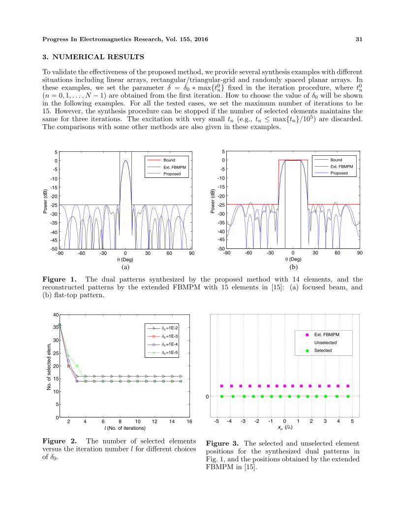
Figure 1. The dual patterns synthesized by the proposed method with 14 elements, and thereconstructed patterns by the extended FBMPM with 15 elements in [15]: (a) focused beam, and(b) flat-top pattern.
02 4 6 8 10 12 14 16
I (No. of iterations)
40
35
30
25
20
15
10
5
No.
of s
elec
ted
elem
.
δ =1E-20
δ =1E-3
δ =1E-4
δ =1E-5
0
0
0
Figure 2. The number of selected elementsversus the iteration number l for different choicesof δ0.
Unselected
Ext. FBMPM
Selected
0
-5 -4 -3 -2 -1 0 1 2 3 4 5x (/λ)n
Figure 3. The selected and unselected elementpositions for the synthesized dual patterns inFig. 1, and the positions obtained by the extendedFBMPM in [15].
32 Liu et al.
3.1. Linear Array
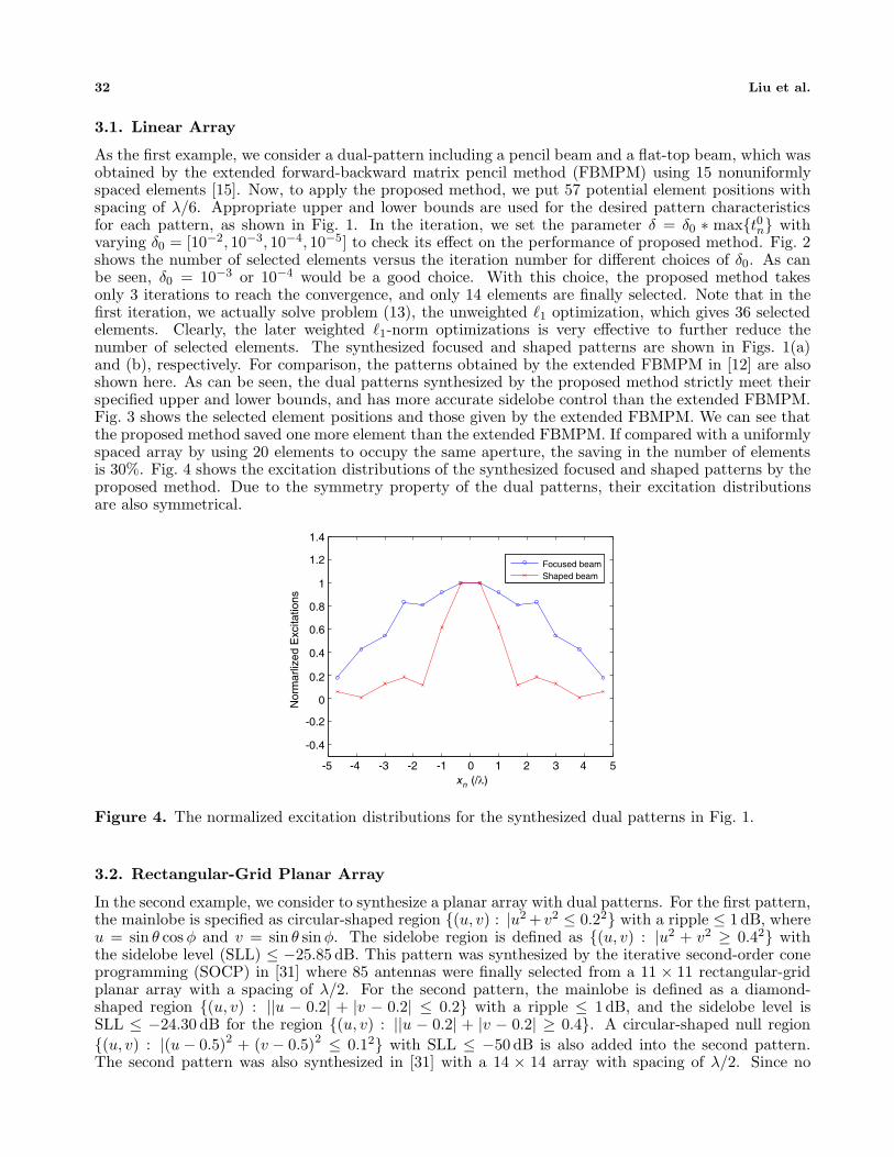
As the first example, we consider a dual-pattern including a pencil beam and a flat-top beam, which wasobtained by the extended forward-backward matrix pencil method (FBMPM) using 15 nonuniformlyspaced elements [15]. Now, to apply the proposed method, we put 57 potential element positions withspacing of λ/6. Appropriate upper and lower bounds are used for the desired pattern characteristicsfor each pattern, as shown in Fig. 1. In the iteration, we set the parameter δ = δ0 ∗ max{t0n} withvarying δ0 = [10−2, 10−3, 10−4, 10−5] to check its effect on the performance of proposed method. Fig. 2shows the number of selected elements versus the iteration number for different choices of δ0. As canbe seen, δ0 = 10−3 or 10−4 would be a good choice. With this choice, the proposed method takesonly 3 iterations to reach the convergence, and only 14 elements are finally selected. Note that in thefirst iteration, we actually solve problem (13), the unweighted �1 optimization, which gives 36 selectedelements. Clearly, the later weighted �1-norm optimizations is very effective to further reduce thenumber of selected elements. The synthesized focused and shaped patterns are shown in Figs. 1(a)and (b), respectively. For comparison, the patterns obtained by the extended FBMPM in [12] are alsoshown here. As can be seen, the dual patterns synthesized by the proposed method strictly meet theirspecified upper and lower bounds, and has more accurate sidelobe control than the extended FBMPM.Fig. 3 shows the selected element positions and those given by the extended FBMPM. We can see thatthe proposed method saved one more element than the extended FBMPM. If compared with a uniformlyspaced array by using 20 elements to occupy the same aperture, the saving in the number of elementsis 30%. Fig. 4 shows the excitation distributions of the synthesized focused and shaped patterns by theproposed method. Due to the symmetry property of the dual patterns, their excitation distributionsare also symmetrical.
-5 -4 -3 -2 -1 0 1 2 3 4 5x (/λ)n
1.4
1.2
1
0.8
0.6
0.4
0.2
0
-0.2
-0.4
Nor
mar
lized
Exc
itatio
ns
Focused beamShaped beam
Figure 4. The normalized excitation distributions for the synthesized dual patterns in Fig. 1.
3.2. Rectangular-Grid Planar Array
In the second example, we consider to synthesize a planar array with dual patterns. For the first pattern,the mainlobe is specified as circular-shaped region {(u, v) : |u2 + v2 ≤ 0.22} with a ripple ≤ 1 dB, whereu = sin θ cos φ and v = sin θ sin φ. The sidelobe region is defined as {(u, v) : |u2 + v2 ≥ 0.42} withthe sidelobe level (SLL) ≤ −25.85 dB. This pattern was synthesized by the iterative second-order coneprogramming (SOCP) in [31] where 85 antennas were finally selected from a 11 × 11 rectangular-gridplanar array with a spacing of λ/2. For the second pattern, the mainlobe is defined as a diamond-shaped region {(u, v) : ||u − 0.2| + |v − 0.2| ≤ 0.2} with a ripple ≤ 1 dB, and the sidelobe level isSLL ≤ −24.30 dB for the region {(u, v) : ||u − 0.2| + |v − 0.2| ≥ 0.4}. A circular-shaped null region{(u, v) : |(u − 0.5)2 + (v − 0.5)2 ≤ 0.12} with SLL ≤ −50 dB is also added into the second pattern.The second pattern was also synthesized in [31] with a 14 × 14 array with spacing of λ/2. Since no
Progress In Electromagnetics Research, Vol. 155, 2016 33
(a) (b)
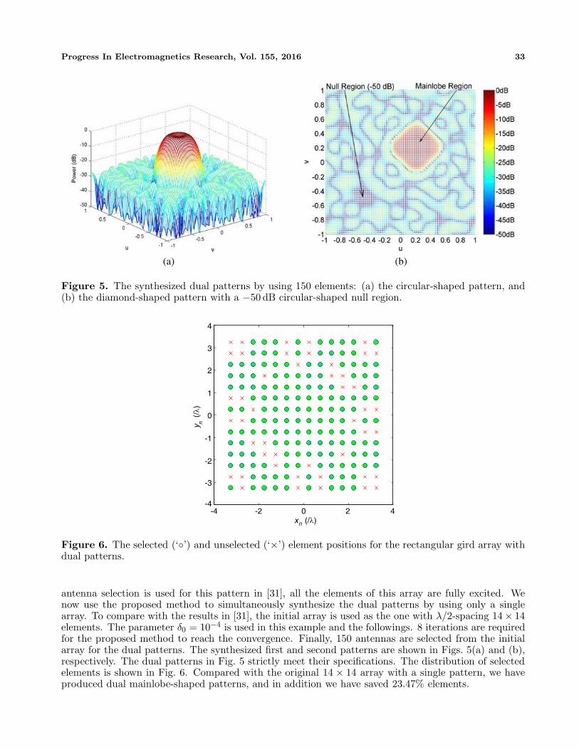
Figure 5. The synthesized dual patterns by using 150 elements: (a) the circular-shaped pattern, and(b) the diamond-shaped pattern with a −50 dB circular-shaped null region.
-4 -2 0 2 4x (/λ)n
y (
/λ)
n
-4
-2
0
2
4
3
1
-1
-3
Figure 6. The selected (‘◦’) and unselected (‘×’) element positions for the rectangular gird array withdual patterns.
antenna selection is used for this pattern in [31], all the elements of this array are fully excited. Wenow use the proposed method to simultaneously synthesize the dual patterns by using only a singlearray. To compare with the results in [31], the initial array is used as the one with λ/2-spacing 14× 14elements. The parameter δ0 = 10−4 is used in this example and the followings. 8 iterations are requiredfor the proposed method to reach the convergence. Finally, 150 antennas are selected from the initialarray for the dual patterns. The synthesized first and second patterns are shown in Figs. 5(a) and (b),respectively. The dual patterns in Fig. 5 strictly meet their specifications. The distribution of selectedelements is shown in Fig. 6. Compared with the original 14 × 14 array with a single pattern, we haveproduced dual mainlobe-shaped patterns, and in addition we have saved 23.47% elements.
34 Liu et al.
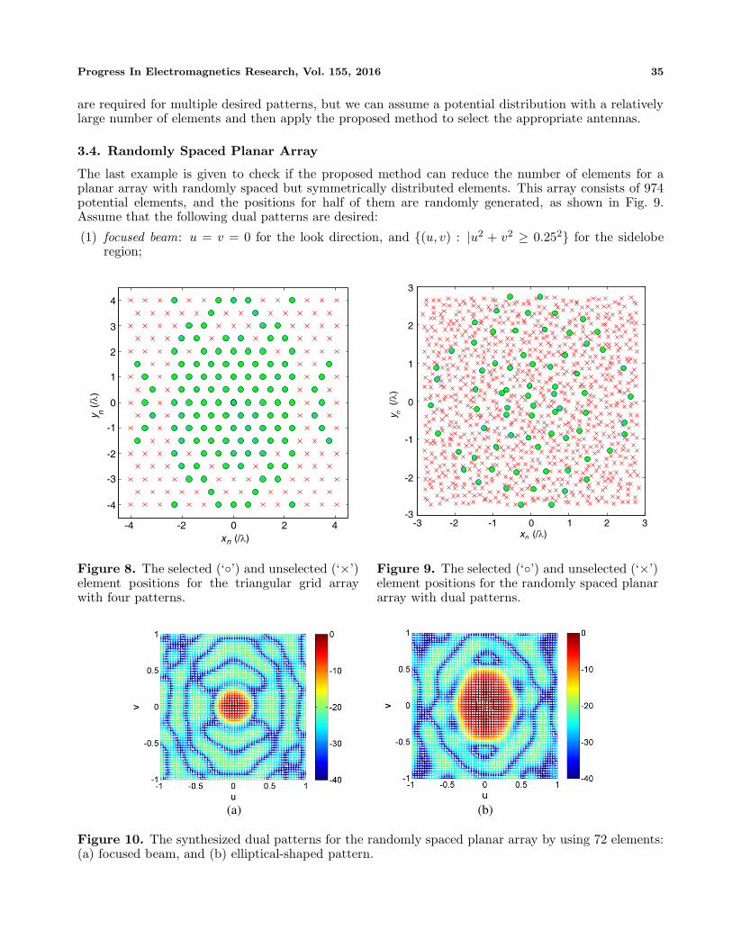
3.3. Triangular-Grid Planar Array
The proposed method can be applied to an arbitrary array with conjugate-symmetrical excitations.As the third example, we consider to synthesize a triangular-grid array with four patterns which havedifferent mainlobe shapes. They are specified as follow:
(1) focused beam: u = v = 0 for the look direction, and {(u, v) : |u2 + v2 ≥ 0.172} for the sideloberegion;
(2) circular-shaped pattern: {(u, v) : |u2 + v2 ≤ 0.22} for the mainlobe region, and {(u, v) : |u2 + v2 ≥0.42} for the sidelobe region;
(3) moon-like pattern: {(u, v) : |(u + 0.35)2 + v2 ≥ 0.52 & u2 + v2 ≤ 0.352} for the mainlobe region,and the outside of {(u, v) : |(u + 0.5)2 + v2 ≥ 0.52 & u2 + v2 ≤ 0.52} for the sidelobe region;
(4) rectangular-shaped pattern: {(u, v) : ||u| ≤ 0.25& |v| ≤ 0.1} for the mainlobe region, and theoutside of {(u, v) : ||u| ≤ 0.4& |v| ≤ 0.2} for the sidelobe region.
Note that the response ripple ≤ 1 dB and SLL ≤ −20 are used for all the patterns in this example. 247potential element positions are used with the spacings of dy = λ/2 and dx = λ/
√3. The proposed
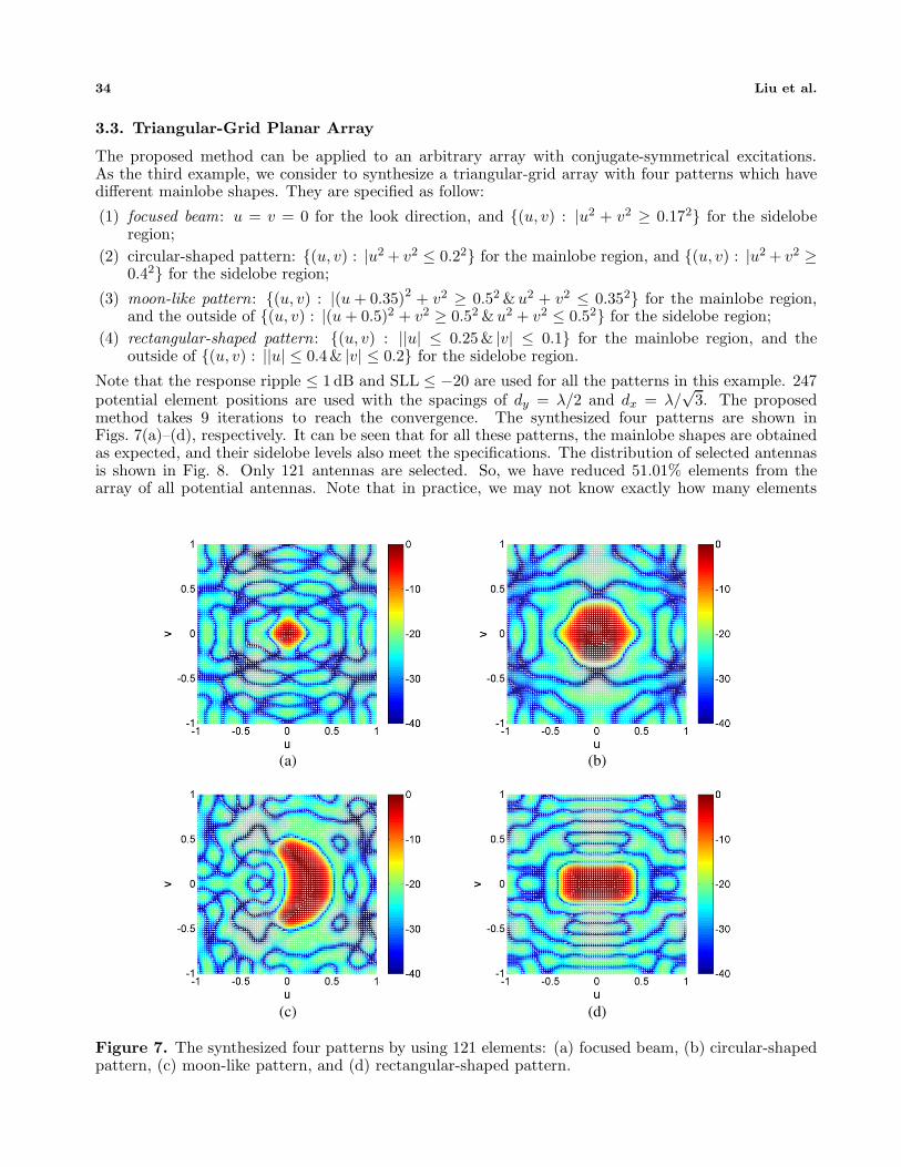
method takes 9 iterations to reach the convergence. The synthesized four patterns are shown inFigs. 7(a)–(d), respectively. It can be seen that for all these patterns, the mainlobe shapes are obtainedas expected, and their sidelobe levels also meet the specifications. The distribution of selected antennasis shown in Fig. 8. Only 121 antennas are selected. So, we have reduced 51.01% elements from thearray of all potential antennas. Note that in practice, we may not know exactly how many elements
(a) (b)
(c) (d)
Figure 7. The synthesized four patterns by using 121 elements: (a) focused beam, (b) circular-shapedpattern, (c) moon-like pattern, and (d) rectangular-shaped pattern.
Progress In Electromagnetics Research, Vol. 155, 2016 35
are required for multiple desired patterns, but we can assume a potential distribution with a relativelylarge number of elements and then apply the proposed method to select the appropriate antennas.
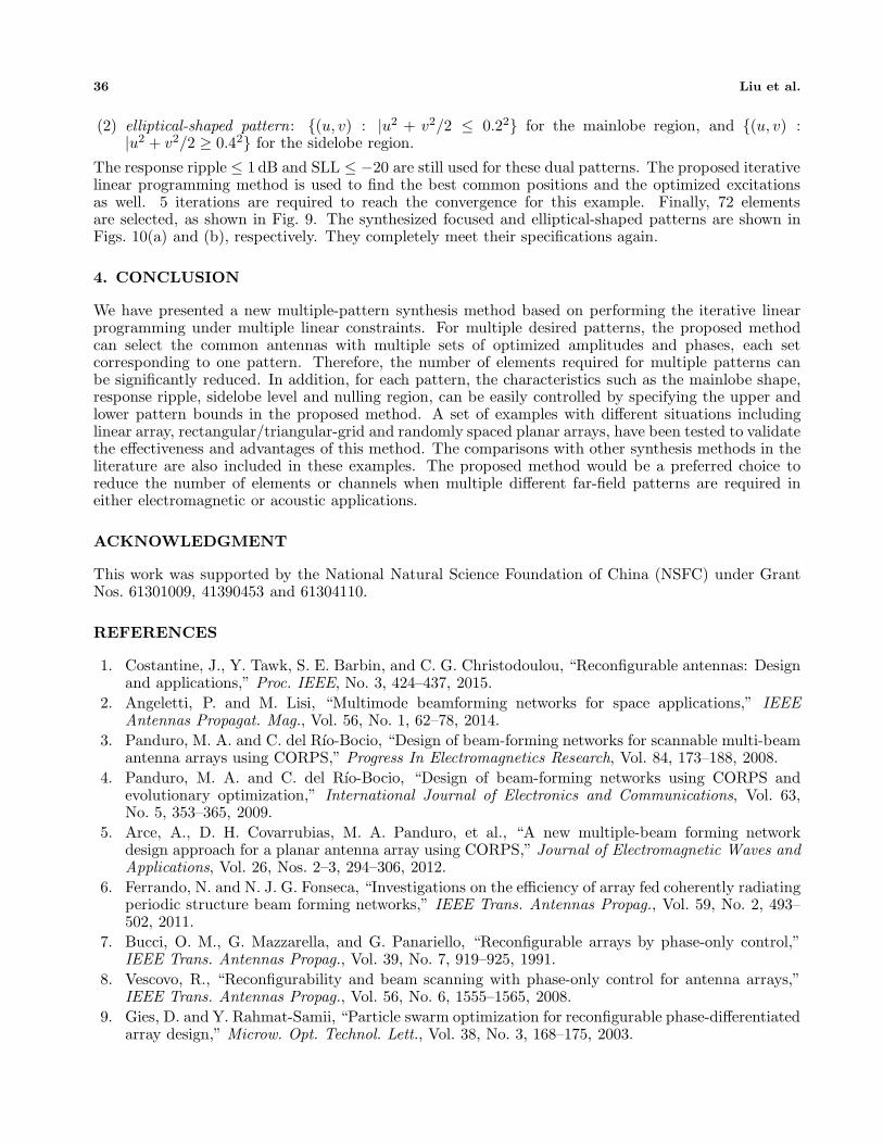
3.4. Randomly Spaced Planar Array
The last example is given to check if the proposed method can reduce the number of elements for aplanar array with randomly spaced but symmetrically distributed elements. This array consists of 974potential elements, and the positions for half of them are randomly generated, as shown in Fig. 9.Assume that the following dual patterns are desired:
(1) focused beam: u = v = 0 for the look direction, and {(u, v) : |u2 + v2 ≥ 0.252} for the sideloberegion;
-4 -2 0 2 4x (/λ)n
y (
/λ)
n
-4
-2
0
2
4
3
1
-1
-3
Figure 8. The selected (‘◦’) and unselected (‘×’)element positions for the triangular grid arraywith four patterns.
-3 -2 0 2 3x (/λ)n
y (
/λ)
n
-2
0
2
3
1
-1
-3-1 1
Figure 9. The selected (‘◦’) and unselected (‘×’)element positions for the randomly spaced planararray with dual patterns.
(a) (b)
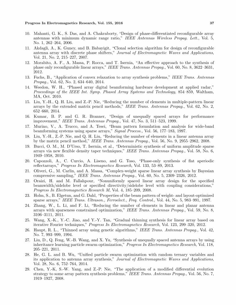
Figure 10. The synthesized dual patterns for the randomly spaced planar array by using 72 elements:(a) focused beam, and (b) elliptical-shaped pattern.
36 Liu et al.
(2) elliptical-shaped pattern: {(u, v) : |u2 + v2/2 ≤ 0.22} for the mainlobe region, and {(u, v) :|u2 + v2/2 ≥ 0.42} for the sidelobe region.
The response ripple ≤ 1 dB and SLL ≤ −20 are still used for these dual patterns. The proposed iterativelinear programming method is used to find the best common positions and the optimized excitationsas well. 5 iterations are required to reach the convergence for this example. Finally, 72 elementsare selected, as shown in Fig. 9. The synthesized focused and elliptical-shaped patterns are shown inFigs. 10(a) and (b), respectively. They completely meet their specifications again.
4. CONCLUSION
We have presented a new multiple-pattern synthesis method based on performing the iterative linearprogramming under multiple linear constraints. For multiple desired patterns, the proposed methodcan select the common antennas with multiple sets of optimized amplitudes and phases, each setcorresponding to one pattern. Therefore, the number of elements required for multiple patterns canbe significantly reduced. In addition, for each pattern, the characteristics such as the mainlobe shape,response ripple, sidelobe level and nulling region, can be easily controlled by specifying the upper andlower pattern bounds in the proposed method. A set of examples with different situations includinglinear array, rectangular/triangular-grid and randomly spaced planar arrays, have been tested to validatethe effectiveness and advantages of this method. The comparisons with other synthesis methods in theliterature are also included in these examples. The proposed method would be a preferred choice toreduce the number of elements or channels when multiple different far-field patterns are required ineither electromagnetic or acoustic applications.
ACKNOWLEDGMENT
This work was supported by the National Natural Science Foundation of China (NSFC) under GrantNos. 61301009, 41390453 and 61304110.
REFERENCES
1. Costantine, J., Y. Tawk, S. E. Barbin, and C. G. Christodoulou, “Reconfigurable antennas: Designand applications,” Proc. IEEE, No. 3, 424–437, 2015.
2. Angeletti, P. and M. Lisi, “Multimode beamforming networks for space applications,” IEEEAntennas Propagat. Mag., Vol. 56, No. 1, 62–78, 2014.
3. Panduro, M. A. and C. del Rı́o-Bocio, “Design of beam-forming networks for scannable multi-beamantenna arrays using CORPS,” Progress In Electromagnetics Research, Vol. 84, 173–188, 2008.
4. Panduro, M. A. and C. del Rı́o-Bocio, “Design of beam-forming networks using CORPS andevolutionary optimization,” International Journal of Electronics and Communications, Vol. 63,No. 5, 353–365, 2009.
5. Arce, A., D. H. Covarrubias, M. A. Panduro, et al., “A new multiple-beam forming networkdesign approach for a planar antenna array using CORPS,” Journal of Electromagnetic Waves andApplications, Vol. 26, Nos. 2–3, 294–306, 2012.
6. Ferrando, N. and N. J. G. Fonseca, “Investigations on the efficiency of array fed coherently radiatingperiodic structure beam forming networks,” IEEE Trans. Antennas Propag., Vol. 59, No. 2, 493–502, 2011.
7. Bucci, O. M., G. Mazzarella, and G. Panariello, “Reconfigurable arrays by phase-only control,”IEEE Trans. Antennas Propag., Vol. 39, No. 7, 919–925, 1991.
8. Vescovo, R., “Reconfigurability and beam scanning with phase-only control for antenna arrays,”IEEE Trans. Antennas Propag., Vol. 56, No. 6, 1555–1565, 2008.
9. Gies, D. and Y. Rahmat-Samii, “Particle swarm optimization for reconfigurable phase-differentiatedarray design,” Microw. Opt. Technol. Lett., Vol. 38, No. 3, 168–175, 2003.
Progress In Electromagnetics Research, Vol. 155, 2016 37
10. Mahanti, G. K., S. Das, and A. Chakraborty, “Design of phase-differentiated reconfigurable arrayantennas with minimum dynamic range ratio,” IEEE Antennas Wireless Propag. Lett., Vol. 5,No. 1, 262–264, 2006.
11. Akdagli, A., K. Guney, and B. Babayigit, “Clonal selection algorithm for design of reconfigurableantenna array with discrete phase shifters,” Journal of Electromagnetic Waves and Applications,Vol. 21, No. 2, 215–227, 2007.
12. Morabito, A. F., A. Massa, P. Rocca, and T. Isernia, “An effective approach to the synthesis ofphase only reconfigurable linear arrays,” IEEE Trans. Antennas Propag., Vol. 60, No. 8, 3622–3631,2012.
13. Fuchs, B., “Application of convex relaxation to array synthesis problems,” IEEE Trans. AntennasPropag., Vol. 62, No. 2, 634–640, 2014.
14. Weedon, W. H., “Phased array digital beamforming hardware development at applied radar,”Proceedings of the IEEE Int. Symp. Phased Array Systems and Technology, 854–859, Waltham,MA, Oct. 2010.
15. Liu, Y.-H., Q. H. Liu, and Z.-P. Nie, “Reducing the number of elements in multiple-pattern lineararrays by the extended matrix pencil methods,” IEEE Trans. Antennas Propag., Vol. 62, No. 2,652–660, 2014.
16. Kumar, B. P. and G. R. Branner, “Design of unequally spaced arrays for performanceimprovement,” IEEE Trans. Antennas Propag., Vol. 47, No. 3, 511–523, 1999.
17. Murino, V., A. Trucco, and A. Tesei, “Beam pattern formulation and analysis for wide-bandbeamforming systems using sparse arrays,” Signal Process., Vol. 56, 177–183, 1997.
18. Liu, Y.-H., Z.-P. Nie, and Q. H. Liu, “Reducing the number of elements in a linear antenna arrayby the matrix pencil method,” IEEE Trans. Antennas Propag., Vol. 56, No. 9, 2955–2962, 2008.
19. Bucci, O. M., M. D’Urso, T. Isernia, et al., “Deterministic synthesis of uniform amplitude sparsearrays via new flexible density taper techniques,” IEEE Trans. Antennas Propag., Vol. 58, No. 6,1949–1958, 2010.
20. Capozzoli, A., C. Curcio, A. Liseno, and G. Toso, “Phase-only synthesis of flat aperiodicreflectarrays,” Progress In Electromagnetics Research, Vol. 133, 53–89, 2013.
21. Oliveri, G., M. Carlin, and A. Massa, “Complex-weight sparse linear array synthesis by Bayesiancompressive sampling,” IEEE Trans. Antennas Propag., Vol. 60, No. 5, 2309–2326, 2012.
22. Oraizi, H. and M. Fallahpour, “Nonuniformly spaced linear array design for the specifiedbeamwidth/sidelobe level or specified directivity/sidelobe level with coupling considerations,”Progress In Electromagnetics Research M, Vol. 4, 185–209, 2008.
23. Holm, S., B. Elgetun, and G. Dahl, “Properties of the beam pattern of weight- and layout-optimizedsparse arrays,” IEEE Trans. Ultrason., Ferroelect., Freq. Control., Vol. 44, No. 5, 983–991, 1997.
24. Zhang, W., L. Li, and F. Li, “Reducing the number of elements in linear and planar antennaarrays with sparseness constrained optimization,” IEEE Trans. Antennas Propag., Vol. 59, No. 8,3106–3111, 2011.
25. Wang, X.-K., Y.-C. Jiao, and Y.-Y. Tan, “Gradual thinning synthesis for linear array based oniterative Fourier techniques,” Progress In Electromagnetics Research, Vol. 123, 299–320, 2012.
26. Haupt, R. L., “Thinned array using genetic algorithms,” IEEE Trans. Antennas Propag., Vol. 42,No. 7, 993–999, 1994.
27. Liu, D., Q. Feng, W.-B. Wang, and X. Yu, “Synthesis of unequally spaced antenna arrays by usinginheritance learning particle swarm optimization,” Progress In Electromagnetics Research, Vol. 118,205–221, 2011.
28. He, G. L. and B. Wu, “Unified particle swarm optimization with random ternary variables andits application to antenna array synthesis,” Journal of Electromagnetic Waves and Applications,Vol. 28, No. 6, 752–764, 2014.
29. Chen, Y.-K, S.-W. Yang, and Z.-P. Nie, “The application of a modified differential evolutionstrategy to some array pattern synthesis problems,” IEEE Trans. Antennas Propag., Vol. 56, No. 7,1919–1927, 2008.

38 Liu et al.
30. Cands, E. J., M. B. Wakin, and S. P. Boyd, “Enhancing sparsity by reweighted l1 minimization,”J. Fourier Analy. Appl., Vol. 14, 877–905, 2008.
31. Nai, S. E., W. Ser, Z. L. Yu, et al., “Beam pattern synthesis for linear and planar arrays withantenna selection by convex optimization,” IEEE Trans. Antennas Propag., Vol. 58, No. 12, 3923–3930, 2010.
32. Fuchs, B., “Synthesis of sparse arrays with focused or shaped beam pattern via sequential convexoptimizations,” IEEE Trans. Antennas Propag., Vol. 60, No. 7, 3499–3503, 2012.
33. Prisco, G. and M. D’Urso, “Maximally sparse arrays via sequential convex optimizations,” IEEEAntennas Wireless Propag. Lett., Vol. 11, 192–195, 2012.
34. Zhao, X.-W., Q.-S. Yang, and Y.-H. Zhang, “Compressed sensing approach for pattern synthesisof maximally sparse non-uniform linear array,” IET Microw. Antennas Propag., Vol. 8, No. 5,301–307, 2014.
35. Isernia, T., O. M. Bucci, and N. Fiorentino, “Shaped beam antenna synthesis problems: Feasibilitycriteria and new strategies,” Journal of Electromagnetic Waves and Applications, Vol. 12, No. 1,103–138, 1998.
36. Sturm, J. F., “Using SeDuMi 1.02, a MATLAB toolbox for optimization over symmetric cones,”Optimization Methods Software, Vol. 11, No. 1–4, 625–653, 1999.