synthesis of technical information for jointless bridge...
TRANSCRIPT

PERFORMANCE MONITORING OF JOINTLESS BRIDGES
Phase I Report
SYNTHESIS OF TECHNICAL INFORMATIONFOR JOINTLESS BRIDGE CONSTRUCTION
14 June 2002
Submitted to:
State of VermontAgency of TransportationNational Life BuildingDrawer 33Montpelier, VT 05633-5001
Submitted by:
Wiss, Janney, Elstner Associates, Inc.Engineers, Architects and Materials Scientists333 North AvenueWakefield, MA 01880781.213.9266 tel/ 781.213.9267 fax
WJE


Phase I Report
SYNTHESIS OF TECHNICAL INFORMATIONFOR JOINTLESS BRIDGE CONSTRUCTION
TABLE OF CONTENTS
1.0 INTRODUCTION ................................................................................................................................. 12.0 THERMAL STRESS ............................................................................................................................. 1
2.1 Coefficient of Thermal Expansion................................................................................................. 12.2 Temperature Range........................................................................................................................ 22.3 Temperature Gradients................................................................................................................... 22.4 Restraint ......................................................................................................................................... 4
3.0 CREEP AND SHRINKAGE STRESS .................................................................................................. 53.1 Creep.............................................................................................................................................. 53.2 Shrinkage ....................................................................................................................................... 63.3 Combined Effect of Creep and Shrinkage ..................................................................................... 63.4 Settlement Stress............................................................................................................................ 7
4.0 SKEW AND CURVATURE ................................................................................................................. 84.1 Mechanics ...................................................................................................................................... 84.2 Distribution of Stresses .................................................................................................................. 9
5.0 ABUTMENT WALL-SOIL INTERACTION....................................................................................... 95.1 Abutment Movement ..................................................................................................................... 95.2 Soil Pressure ................................................................................................................................ 105.3 Soil Stiffness ................................................................................................................................ 11
6.0 PILE-SOIL INTERACTION ............................................................................................................... 126.1 Soil Stiffness ................................................................................................................................ 126.2 Failure Mechanisms ..................................................................................................................... 136.3 Capacity Reduction from Lateral Displacement .......................................................................... 136.4 Pre-drilled Holes .......................................................................................................................... 14
7.0 FLEXIBILITY OF THE SUBSTRUCTURE ...................................................................................... 157.1 Pile Orientation ............................................................................................................................ 157.2 Superstructure to Substructure Stiffness Ratio ............................................................................ 157.3 Boundary Conditions ................................................................................................................... 16
8.0 ALTERNATIVE SUPPORT SYSTEMS ............................................................................................ 179.0 SPECIAL CONSIDERATIONS FOR CYCLIC LOADING .............................................................. 18
9.1 Soil Stiffening and Settlement ..................................................................................................... 189.2 Fatigue Cracking of Piles............................................................................................................. 19
10.0 APPROACHES.................................................................................................................................... 1911.0 WINGWALLS..................................................................................................................................... 2012.0 PRACTICAL CONSIDERATIONS.................................................................................................... 20
12.1 Length and Movement Limitations............................................................................................. 2112.2 Construction Sequence................................................................................................................ 2112.3 Steel vs Concrete Girders............................................................................................................ 21
13.0 DISCUSSION OF LITERATURE SYNTHESIS................................................................................ 2213.1 Phase II Study ............................................................................................................................. 23
14.0 CONCLUSION.................................................................................................................................... 27CITED REFERENCESFIGURESAPPENDIX A - Summary of QuestionsAPPENDIX B - Comprehensive Bibliography

Phase I ReportSYNTHESIS OF TECHNICAL INFORMATION
FOR JOINTLESS BRIDGES
1
1.0 INTRODUCTION
The primary concern in the design of integral bridges1 is that high stresses can develop in thesuperstructure and substructure as a result of secondary loads because of the continuity connectionbetween the superstructure and the substructure. These stresses are the result of restrained thermalexpansion and contraction, creep, shrinkage, and settlement. The thermal-induced movement of anintegral bridge has been shown to induce larger stresses in integral bridge components than live loads(Lawver et al, 2000) and should, therefore, be given careful consideration. The stresses developed as aresult of thermal movement are functions of bridge geometry, soil properties, and pile design amongothers. Because of the complex interaction between the variables affecting bridge performance, especiallythe soil-structure interaction, the stress levels are difficult to predict. The effects of creep and shrinkagehave largely been ignored because their effects tend to act against each other and have been consideredsmall in relation to the effects of thermal movement. Settlement stresses are often ignored as well and arenot well understood in integral bridges.
Despite the uncertainty and complexity of integral bridge behavior, many states are adopting the jointlessbridge concept. A recent survey received responses from 39 states or provinces (Kunan and Alampalli,2000). Of those, only eight had no experience with integral abutment bridges, and only Arizona reportedpoor performance and is no longer constructing integral bridges. Several states, such as California andTennessee, have constructed more than 1,000 integral bridges over the last 40 years or more and haveamassed a history of good performance.
This report provides a synthesis of the research conducted on integral abutment bridges in order todescribe the behavior of bridges utilizing the jointless concept. The report focuses on research conductedon bridges with continuous connections of the slab and girders to the abutment wall, as opposed to semi-integral bridges, which do not have a continuous connection between the girders and the abutment.Furthermore, this report is intended to describe the key variables that affect integral bridge behavior andperformance. It is not intended to be a summary of current design practices. As this study will ultimatelylead to recommendations for bridge instrumentation programs, it was necessary to structure the reportcontent in this manner. The report highlights key variables that may require consideration in a futureinstrumentation program.
2.0 THERMAL STRESS
High stresses can develop in the components of an integral bridge when the structure undergoes thethermal length changes of its bridge deck. Differences often exist in measured and theoretical temperatureinduced length changes and is one reason why integral bridges in some states have performedsatisfactorily even though structural analysis indicated there should have been thermal stress problems.These differences can be attributed to errors in the coefficient of thermal expansion, temperature gradientsacross the bridge cross sections, and resistance to movement provided by the abutment system and thesoil pressure, which depend on the poorly understood soil-structure interaction.
2.1 Coefficient of Thermal Expansion
Some researchers have concluded that differences between the measured thermal length change of abridge and the theoretical thermal length change can be attributed to a difference between the measuredand assumed coefficient of thermal expansion. The coefficient of thermal expansion is a function ofcement quality, aggregates, mix proportions, temperature, humidity, and concrete age and, therefore, can
1 Also called integral abutment bridge (IAB), jointless bridge, rigid-frame bridge, or U-frame bridge.

Phase I ReportSYNTHESIS OF TECHNICAL INFORMATION
FOR JOINTLESS BRIDGES
2
vary widely from the commonly assumed value of 6.0x10⁻⁶ in/in/°F. Girton et al (1991) found that thecoefficient for the bridges in their study ranged from 4.5x10⁻⁶ in/in/°F to 5.0x10⁻⁶ in/in/°F. ConstructionTechnology Laboratories researchers (Oesterle et al, 1998) experimentally determined an averagecoefficient of 4.9x10⁻⁶ in/in/°F.
Because thermal movements of integral bridges are a key parameter of their behavior, it is important tomake an accurate estimate of the coefficient of expansion. The American Concrete Institute (ACI)publication ACI 209R provides an empirical equation to estimate the coefficient of thermal expansionbased on the environmental conditions and aggregate characteristics. Methods developed by Emanuel andHulsey (1977) may also be used to determine an accurate estimate when the concrete mix design isknown.
2.2 Temperature Range
There is a lag between the ambient air temperature and the temperature of the bridge components, whichaffects the design temperature range of the bridge. The lag is primarily affected by the materials used inbridge construction. Hybrid structures (those with steel girders and a concrete deck) tend to follow theextremes of ambient temperature more closely than concrete structures. This can be attributed to thelarger thermal mass of concrete structures and the difference in thermal conductivity and diffusivitybetween steel and concrete. This is reflected in the AASHTO Standard Specifications for HighwayBridges, which recommends larger design temperature ranges for hybrid structures.
It has been suggested that the temperature ranges given by AASHTO are not accurate enough for integralbridge design and that temperature ranges should be determined on a regional or local level. Flores (1994)compared the temperature ranges from several studies to the AASHTO temperature recommendations.Results indicate that the AASHTO temperature ranges are too conservative for steel stringer bridges andmay underestimate the temperature range for concrete bridges. The differences in the temperature rangesbetween hybrid and concrete bridges in the studies were much smaller than those suggested by AASHTO.
Jorgenson (1983) monitored an integral bridge with a concrete deck and concrete box girders todetermine, in part, how the lag in bridge temperature affected the design temperature range. He found thatthe lag was non-linear, with similar bridge and air temperatures recorded at approximately 7 a.m. and 6p.m. Applying the standard coefficient of expansion to the change in temperature of the concrete deckover a 24-hour period over-estimated the total expansion by more than 100%. The difference wasattributed to thermal gradients in the bridge setup, in part, due to lags in heating and cooling across theconcrete mass. It should be noted that the report does not indicate if Jorgenson measured the actualcoefficient of expansion to determine if a difference between the actual and assumed coefficientcontributed to the error. Calculating the change in length of the bridge based on deck temperatures atsunrise each day over the course of a year gave a good correlation to measured length changes. Therefore,Jorgenson proposed calculating the design temperature range as the temperature difference between dawnon the hottest and coldest day of the year and adding one-third of the difference between the maximumtemperature and the temperature at dawn during the hottest day of the year.
2.3 Temperature Gradients
Temperatures throughout a bridge structure are not uniform because of varying rates of heat transfer ofdifferent materials, heat sources and sinks, and varying exposure to direct solar radiation. The stressesinduced by thermal gradients have been compared to those caused by creep and shrinkage (Arsoy et al,1999 and Burke, 1993) which are typically ignored. However, Hoppe and Gomez (1996) noted that thestresses in steel girders caused by daily temperature fluctuations might be more critical than the

Phase I ReportSYNTHESIS OF TECHNICAL INFORMATION
FOR JOINTLESS BRIDGES
3
compressive forces caused by the restraining force of the backfill. The stresses developed in the bridgecomponents as a result of thermal gradients are affected by the gradient distribution, the relativeflexibility of the substructure, and the materials used in the bridge (concrete vs. steel girders). Researchhas indicated that the stresses can vary widely, even change sign, depending on the previously notedconditions.
There is fairly wide agreement that temperature gradient distributions are nonlinear through the depth ofthe superstructure (Russell and Girken, 1994). However, a bilinear distribution was measured by Girton etal (1991), who found moderate temperature gradients in pre-stressed concrete girders with a steeptemperature gradient in the slab. An analytical model by Sayers (2000) predicted a nonlinear distributionof temperature strains through the depth of the superstructure. He noted that internal strains lead tocompressive stresses in the deck and tensile stresses in the girders as a result of the difference between theunrestrained temperature length change and the actual final profile, which is assumed to remain plane, asshown in Figure 1a. This particular case holds true when the coefficient of expansion of the deck issimilar to the coefficient of expansion of the girders.
The effect of asphalt topping on the internal temperature distribution is not clear. It seems intuitive toassume that the dark surface will absorb more solar radiation than a concrete surface and, therefore, createa larger thermal gradient in the superstructure. However, it has been reported that asphalt surfacing acts asinsulation and actually reduces the maximum temperature in the deck concrete (Potgieter and Gamble,1989). Elbadry and Ghali (1983) conducted a numerical analysis and found that an asphalt toppingincreased the temperature-induced stresses in the concrete. Clearly additional study is needed to clarifythe effect of asphalt topping.
The superstructure behavior is greatly influenced by the relative stiffness of the abutment. Aspile/abutment systems become more flexible, they provide less restraint against induced superstructurecurvature, such that gradient-induced axial and bending stresses in the superstructure will typically belower than expected. Thippeswamy et al (1994) conducted a two dimensional frame analysis of a hybridbridge and abutment and measured the effects of temperature gradients on the maximum moments. Theyfound that as the flexibility of the abutment increased (i.e. the ratio of superstructure to substructurestiffness increased) the bending stresses at midspan due to the temperature gradient decreased.
When superimposed on the stresses from dead and live load, thermal gradient stresses may reverse thesign of the axial stresses in the superstructure. Thippeswamy and GangaRao (1995) conducted a twodimensional frame analysis of five steel girder integral bridges and found that a temperature gradient of30°F through the depth of the superstructure produced considerable tensile stresses at thesuperstructure/abutment joint. Five abutment systems were checked. Systems A, B, and C were spreadfooting abutments with a fixed base, pinned base with pinned intermediate pier, and pinned base with freeintermediate pier, respectively. Systems D and E were pile-supported abutments with piles oriented forstrong axis and weak axis bending, respectively. The thermal gradient stresses for the various systems atseveral locations throughout the structure are shown in Table 1. As shown in Table 1, stress at the bottomof the steel girders at the abutment joint switched from tension to compression when spread-footingabutments were used.
Because full composite action was assumed in the model, the top of the steel girder, which has a largercoefficient of expansion than concrete, could cause tensile stresses in the deck if the gradient and depth ofthe concrete are shallow enough to allow the free expansion of the steel girder to exceed that of theconcrete deck. Compressive stresses would then be present in the top portion of the steel girder. Thisconcept is illustrated in Figure 1b. This stress distribution contrasts with the idealized distribution for ahomogeneous deck/girder under a typical temperature gradient, as shown in Figure 1a.

Phase I ReportSYNTHESIS OF TECHNICAL INFORMATION
FOR JOINTLESS BRIDGES
4
TABLE 1 - Summary of Thermal Gradient Stresses from Thippeswamy and GangaRao
Stresses (psi)LocationSystem A System B System C System D System E
Superstructure/Abutment Joint
TopBottom
123-8,290
934-8,580
914-8,580
4807,560
4797,580
Midspan TopBottom
-2782,590
3097,910
3097,910
31812,000
31712,010
Pier TopBottom
449,680
45214,490
45214,950
81210,240
81310,240
Note: Tensile stress is positive.
It is not clear why such high compressive stresses were developed at the bottom of the steel girders withnegligible stresses in the concrete deck when spread footing systems were used. Compressive stressescould be achieved in the girders if the abutment was sufficiently rigid to restrain the expansion of thecomposite section, as illustrated by Figure 1c, but compressive stresses might also be expected in theconcrete deck. To provide this restraint, the footing and soils would have to be sufficiently rigid toprevent significant rotation and translation of the abutment wall to accommodate the length change of thesuperstructure. As will be discussed shortly, abutment systems typically rotate and translate toaccommodate expansion of the superstructure, so Systems A through C do not likely represent practicalfield conditions.
Temperature gradients in the superstructure do not have a significant effect on the stresses in the piles orfootings, although they may cause the redistribution of load to the piles. Thippeswamy and GangaRao(1995) found that thermal gradient induced stresses were negligible in foundation systems consisting ofpiles or flexible spread footings. Lawver et al (2000) monitored a 216.5 ft (66 m) long integral bridgewith H-piles oriented for weak-axis bending. They observed that the magnitude of the compressive axialstrain in the exterior pile decreased while the magnitude of the axial strain in the interior pile increased asthe deck temperature increased. They attributed this to thermal gradients across the width of the deck,which caused the redistribution of dead load to the abutment piles.
There are several situations where thermal gradients have typically been ignored, apparently with noadverse side effects. The stresses induced by thermal gradients are often ignored in moderate climates(Arsoy et al, 1999). Burke (1993) reported that the sum of secondary effects is very small in comparisonto the load effects for bridges less than 300 feet long and can usually be ignored with the exception ofsingle span bridges and the continuity connection of continuous spans.
2.4 Restraint
The soil behind the abutment wall provides restraint against thermal expansion that will affect the overalllength change of the bridge and induce secondary stresses in the structure. However, the restraintprovided by abutment wall backfill is usually considered ineffective in reducing the free thermalexpansion of the superstructure because the superstructure to abutment stiffness ratio in the direction ofbridge expansion is high, and the reactive soil pressure at the top of the wall is often considered low.Observations of integral bridges have confirmed that the soil restraint does not significantly reduce theexpansion of the bridge.
Several bridges monitored by Lawver, French, and Shield (2000) exhibited nearly free expansionbehavior. The theoretical unrestrained length change nearly matched the measured length change for the
Phase I ReportSYNTHESIS OF TECHNICAL INFORMATION
FOR JOINTLESS BRIDGES
5
66 meter prestressed concrete bridge investigated when using a coefficient of thermal expansion of10.5x10-6/°C (approximately 6.0x10⁻⁶/°F) and the temperature change measured at the girders. Thetheoretical length change also nearly matched the measured length change in a study conducted by Girtonet al (1991). However, it was noted that the AASHTO coefficient of thermal expansion was considerablyhigher than the experimentally determined coefficient and the temperature range was significantly smallerthan the measured range. Elgaaly et al (1992) measured strains in the steel frame of an integral bridge andfound they correlated well with free thermal expansion of the bridge. Construction TechnologyLaboratories (Oesterle et al, 1998) found that abutment and pier restraints (soil restraint) had a negligibleeffect on thermal expansion of the bridge in their study. Finally, Sayers (2000) conducted a finite elementanalysis that varied soil stiffness behind the abutment wall and at the level of the piles. The overallchange in bridge length was relatively unaffected by the original stiffness of the soils at the piles. Hereported that the magnitude of the bridge expansion and hence the longitudinal displacement at the top ofthe abutment, will be nearly the same regardless of the amount of rotation the abutment must undergo toaccommodate the length change.
Although it does not appear that restraint from soils significantly influences the overall expansion of thesuperstructure, varying soil properties at each end of a bridge can have a significant impact on thedistribution of the length change. Jorgenson (1983) measured an abutment movement of 1.96 inches onone side of the bridge while the opposite abutment moved 0.74 inches. This was attributed to thedifference in effective soil stiffness. Thomas (1999) also measured unequal abutment movement. Thesouth end of the bridge experienced a decreased rate of expansion as the temperature rose and the northend experienced an increased rate of expansion, but the net expansion of the bridge maintained a linearrelationship with the change in temperature. Thomas hypothesized that the non-uniformity was due toincreasing backfill stiffness behind the south abutment as the abutment expanded. A similar change instiffness was not mobilized behind the north abutment.
3.0 CREEP AND SHRINKAGE STRESS
The effects of creep and shrinkage are often assumed to have opposite effects and are difficult to quantify,particularly considering the composite construction and continuity of integral bridges. Therefore, creepand shrinkage are commonly ignored in the evaluation and design of jointed bridges. Results fromnumerical analysis show that the effects can be additive in certain regions of integral bridges that consistof steel girders and a concrete deck.
3.1 Creep
Thippeswamy and GangaRao (1995) conducted numerical analysis of five integral bridges with steelgirders designed for composite action with the concrete deck. For pile-supported abutment bridges, creepdecreased the compressive dead load stress in the girder at the abutment connection by about 10%. Forintegral bridges on spread footings, creep decreases compressive dead load stress in the girder at theabutment by about 40%. It should be noted that the live load stresses at the abutment are very low ascompared to the dead load stresses. When creep effects are combined with dead and live load, theintegral abutment bridge behaves more like a continuous structure with simple supports at the abutment.This is only true for bridges founded on spread footings or piles aligned in weak axis bending. Creepstresses at midspan decreased the top compressive dead load stress nearly 40% and increased the tensilestress at the bottom of the superstructure slightly less than 10%. Over piers, top tensile dead load stresswas reduced about 50% and bottom compressive stress increased a maximum of 10%. They found thatcreep stresses were greater in the fixed spread-footing model but were lower for hinged spread footingsand piles. Figure 2 summarizes the stresses from primary loads, creep, and shrinkage at critical areas of

Phase I ReportSYNTHESIS OF TECHNICAL INFORMATION
FOR JOINTLESS BRIDGES
6
the bridge superstructure for a hybrid integral bridge, i.e. steel superstructure with composite concretedeck. As illustrated in the figure, the overall effect of creep is to reduce the stresses in the bridge deck andincrease the stresses in the girder.
Siros and Spyrakos (1995) also conducted a numerical analysis of a composite integral bridge. Theyconcluded that the creep stresses in the concrete deck were as high as 26% to 55% of the dead loadstresses and the creep stresses in the steel were between 2% and 21% of the dead load stresses. The resultsof Thippeswamy and GangaRao’s (1995) study indicate that creep stresses reduce the magnitude of thestresses in the concrete deck, so the high percentages in the deck are not a concern. However, creep addsto the stress at the bottom of the superstructure. The creep stresses in the steel girders correlated to 1% to9% of the allowable stress for steel. In concrete girders, the creep stresses are 3% to 42% of the allowablefor concrete.
It should be noted that the reduction of top-of-slab compressive stresses at midspan can theoretically belarge enough to eventually produce tensile stresses (McHenry, 1943). However, Siros and Spyrakos(1995) reported that this has not been observed in the analysis of several bridges of various span lengthsand geometries.
3.2 Shrinkage
Bridges composed of a cast-in-place deck and steel or precast concrete girders will have a non-uniformshrinkage through the depth of the structure. Because the steel or precast girders restrain the freeshrinkage of the concrete deck, tensile stresses are developed in the concrete and compressive stresses aredeveloped in the girders at midspan, including regions over piers as long as the superstructure is free toslide over the piers. Research by Thippeswamy and GangaRao (1995) confirms this behavior. Shrinkagestresses were small in the concrete deck, less than 300 psi tensile, and had a much larger effect on thesteel girders, up to 4,000 psi compressive. Shrinkage of the deck concrete produced small tensile stressesin the girder at the abutment/ superstructure joint because the slab shrinkage would tend to pull the girderfrom its integral connection. The free body diagram of the steel girder in Figure 3 illustrates this.
As illustrated by Figure 2, stresses caused by shrinkage in hybrid integral bridges are opposite in sign tothose produced as a result of dead and live load towards mid-span and the same in sign as the stressesproduced in negative moment regions over piers. At the abutment/superstructure connection, the tensilestresses at the top of the joint are additive and the stresses towards the bottom of the joint are opposite insign. If the additional tensile stress over piers and at the abutment joints are not accounted for in design,hinges could form as the concrete cracks and the superstructure may behave like a simply supported spanat the intermediate pier. As mentioned previously, the flexibility of the pile-supported abutment systemallowed the structure to behave like a simply supported span at the abutment connection.
3.3 Combined Effect of Creep and Shrinkage
The assumption that creep and shrinkage forces tend to cancel each other out does not appear to be validfor hybrid integral bridges. As shown in Figure 2, the creep and shrinkage stresses are similar in sign atthe top of the superstructure at mid-span and at the bottom of the structure over piers. Additionally, atlocations where the stresses are opposite in sign, they are not equal. The combined effects of creep andshrinkage are shown in Figure 2d. The creep and shrinkage stresses are much larger than the primary loadstresses in the girder at the abutment and change the stress there from compressive to tensile. Combinedtensile stresses in the slab at mid-span reduce the magnitude of the compressive stress from primaryloads. The other significant effect is that compressive stress in the girder over piers was increased by 20%by the combined effects of creep and shrinkage.

Phase I ReportSYNTHESIS OF TECHNICAL INFORMATION
FOR JOINTLESS BRIDGES
7
Descriptions of creep and shrinkage for concrete girder bridges by Burke (1993) indicate that creep hasthe opposite effect of shrinkage at all locations. As discussed above, this may not be an accuratestatement. Shrinkage stresses discussed by Burke (1993) were similar in nature to those described above.Following research completed by Mattock (1961), he noted that maximum shrinkage moments occurwithin 30 days of form striping with negligible creep effects. Creep effects balance shrinkage effects after7 to 8 months. After about 2 years, the continuity moments at the abutment connection and verticalreactions (not considering primary loads) are reversed.
There is limited information available on the shrinkage and creep stresses in the foundation system.Thippeswamy and GangaRao (1995) indicated that shrinkage stresses at the foundations were negligiblefor all footing systems except for a fixed spread footing.
3.4 Settlement Stress
Settlement of the abutments of an integral bridge is typically a result of cyclic loading of the soil and thevertical loads on the abutments or approach slab. Washout and scour also cause settlements in bridgesspanning bodies of water or bridges with a defective means of preventing significant amounts of waterfrom infiltrating the backfill. The effects of settlements on the stresses in integral bridges have not beenthoroughly studied, and the available information is somewhat conflicting.
A study by GangaRao (1981) determined that, for two and four span steel stringer bridges, a differentialsettlement of one inch or more would produce unacceptable stresses for spans of up to 50 feet. Effects ofa 3 in. settlement were small for bridges with 100 to 200 foot spans and negligible for bridges with spansgreater than 200 feet. He concluded that the settlement stresses in a single span bridge were insignificantand could be disregarded in analysis and design.
Integral bridges supported by spread footings appear to develop high stresses in the superstructure at theabutment joint whereas bridges supported by flexible piles develop much lower stresses under the samesettlement. It is not entirely clear why the same settlement produces different stresses in thesuperstructure, although it is likely related to the stiffness and deflected shape of the abutment system.Thippeswamy and GangaRao (1995) conducted a numerical analysis and reported that the stress in thesuperstructure at the abutment due to spread footing settlement was nearly a quarter of the dead loadstress and had the same effect as primary loads. The settlement stress was negligibly small at thesuperstructure/abutment joint for bridges on piles and at the bottom of the abutment for all systems.
Information presented by Burke (1993) conflicts with the suggestion that settlement stresses have thesame effect as primary loads. Burke (1993) stated that settlement of abutments of multiple span integralbridges induces bending moments in the superstructure similar to those induced by shrinkage, andsettlement of piers induces moments similar to those induced by creep. In both cases, the moments at thepiers are opposite to and substantially greater than those at the abutments. Greimann et al (1986) alsoconducted a numerical analysis of the effects of abutment pile settlement. The load-settlement curveswere unaffected by pile orientation, thermal movements of the superstructure, or the presence of backfillbehind the abutment wall. After about 0.25 inches of vertical settlement the piles were unable to carrysubstantial additional load.

Phase I ReportSYNTHESIS OF TECHNICAL INFORMATION
FOR JOINTLESS BRIDGES
8
4.0 SKEW AND CURVATURE
Skew and curvature are problematic for bridges of all types. The mechanics of skewed bridges are fairlywell understood, but much less is known about the effects of curvature. Most states that use integralbridges have adopted an upper limit skew of 20 to 30 degrees based on performance data of in-serviceintegral bridges. In the past decade, several studies have investigated the effect of bridge skew throughexperimental and analytical methods to provide refined design guidelines. It has been found that higherskew angles result in lateral displacements of the abutment wall towards the acute side of the bridge withcorresponding high stresses in the superstructure and substructure nearest the obtuse corners.
4.1 Mechanics
The skew of a bridge, abutment wingwalls, and length-to-width ratio of the bridge affect the magnitude oftransverse movement of the abutment. Figure 4 illustrates the reaction forces acting on an expandingbridge. Because the abutment walls on skewed bridges are not perpendicular to the centerline of thebridge, the resultant soil pressure force has a component normal to the abutment wall and a componentparallel to the abutment wall. The normal force couple acting on the bridge will tend to cause rotation ofthe abutment and superstructure about a vertical axis such that the acute corners of the abutment wallsmove away from the soil (clockwise in Figure 4). The force-couple from frictional resistance of the soilcauses rotation in the opposite direction and balances the reactive pressure force couple. The frictionalresistance consists of the friction force between the backfill and the abutment wall and the internalshearing resistance of the backfill. Usually the frictional resistance between the wall and the soil issmaller than the internal shearing resistance of the soil and will, therefore, control behavior of the backfillinterface (Burke, 1994). If the frictional force of the soil is exceeded, the force couple will be unbalancedand the bridge will rotate.
As the skew increases, the soil pressure reaction force due to thermal expansion of the bridge has a largercomponent in the transverse direction. Thus, as the skew of a bridge increases, the frictional resistance ismore likely to be exceeded. The literature indicates that skew angle greater than 15 to 20 degrees causeforces sufficient to move the abutments (Burke, 1994; Sayers, 2000). Burke showed that skews greaterthan 15 degrees cause instability and require guide bearings for semi-integral bridges with a backfill angleof friction of 22 degrees. He makes a valid case that the force required to stabilize rotation of theabutments on a 30 degree skewed abutment approaches 50% of the passive pressure on the abutment walland 70% for a 45 degree skewed abutment. These values far exceed the frictional resistance of the wall orthe shearing resistance of the soil.
If the frictional resistance between the soil and the wall is exceeded, the piles must resist the deficit forceparallel to the abutment wall and the wall will move laterally as the piles deflect. The lateral deflection ofthe piles is affected by the magnitude of the forces, the stiffness of the piles and soil, and the pile-soilinteraction. Piles will be biaxially stressed if the web of the pile is parallel or perpendicular to theabutment wall. For piles with webs perpendicular or parallel to the centerline of the roadway, the pilestresses are similar to bridges without skew (Greimann et al, 1983).
It should be noted that longer abutment walls (wider bridges) offer greater frictional resistance to lateralmovement. Wingwalls can also act to restrain the soil and may provide additional transverse supportdepending on the abutment to wingwall connection, the wingwall orientation, and the wingwallinteraction with the soil.
The behavior of curved girder bridges is more unpredictable than straight skewed bridges. It is unclear ifthe overall thermal movements follow the chord between abutments, the chord between consecutive

Phase I ReportSYNTHESIS OF TECHNICAL INFORMATION
FOR JOINTLESS BRIDGES
9
supports, or act perpendicular to the abutments. Field measurements (Roeder and Moorty, 1991) haveindicated that thermal expansion can be radial depending on the slenderness of the supporting piers.
4.2 Distribution of Stresses
Soil pressures from thermal loads and live loads are greatest at the obtuse sides of a skewed bridgebecause of the rotation of the abutment wall, which tends to push the obtuse side into the soil and pull theacute side away. It should be noted that the pressure at the acute side is still likely to be positive becauseof the overall elongation of the bridge.
Sandford and Elgaaly (1993) and Elgaaly et al (1992) observed stresses on the upper part of the abutmentwall at the obtuse corner of a 20 degree skewed Forks Bridge in Maine that were nearly three times thevalue at the acute corner. They also noted that the pressures caused by thermal expansion were of thesame magnitude or higher than the live load response. During periods of expansion, the pressure on theobtuse side increased four to six times the cold weather value, whereas the acute side pressure increasedtwo to three times. These differences occurred seasonally as a result of long-term temperature changesand were relatively unaffected by short-term variations, indicating that the difference was not a reflectionof non-uniform temperatures in the structure. The pressure differences on cells 6 feet lower on theabutment wall were categorized as almost negligible. The effect of skew also appeared to be diminishingwith each annual cycle so there was no indication that cyclic stiffening of the soil was increasing pressuredifferences.
The live load response of integral bridges also appears to cause higher stresses at the obtuse corner of abridge. Elgaaly et al (1992) observed that the soil pressure near the obtuse corner side of the abutmentwall increased while the acute side soil pressure decreased during live load tests. Dagher, Elgaaly, andKankam (1991) concluded that the shear and moments from primary loads were relatively high near theobtuse corner of the slab. The report also pointed out that slab cracking had recently been observed nearthe obtuse corner of an integral bridge in Maine.
Thomas (1999) measured lower pier strains at the obtuse angle side of a 30 degree skewed bridge whencompared to the acute angle side. Although the soil pressure behind the abutment wall was not measured,the lower pier strains indicate that there was more restraint against longitudinal movement at the obtuseside and, therefore, higher soil pressures at the obtuse side.
5.0 ABUTMENT WALL-SOIL INTERACTION
The soil-structure interaction has the largest single influence on the behavior of integral bridges.Unfortunately, it is also the most difficult to accurately predict because the reactive soil pressures are anon-linear function of the magnitude of the displacement and deflected shape of the wall, and thedeflected shape of the wall is a function of soil pressures. Variables that affect the soil-abutmentinteraction include abutment wall, pile, wingwall, approach slab, and pile configurations; soilcharacteristics (primarily soil stiffness); total movement; and superstructure stiffness among others.
5.1 Abutment Movement
Abutment movement is the result of two effects: the thermal movement of the superstructure and thetemperature dependant volumetric expansion of the pile cap concrete. The volumetric expansion of thepile cap concrete is small in comparison to the thermal expansion and contraction of the bridge and isusually ignored. Thermal expansion of the bridge pushes the abutment wall into the soil, which affects the

Phase I ReportSYNTHESIS OF TECHNICAL INFORMATION
FOR JOINTLESS BRIDGES
10
earth pressure on the abutments, piles, diaphragms, and wingwalls, and causes movement of the approachslabs. Thermal expansion behavior of the superstructure was discussed earlier. The abutment walls canalso translate laterally, as described in the discussion on bridge skew.
It is important to understand the deflection behavior of abutment walls to arrive at an understanding of thesoil-abutment interaction. Thermal gradients in the bridge superstructure and the eccentricity of the soilpressure resultant force with respect to the height of the superstructure produce forces that tend to rotatethe abutment as shown in Figure 5. Research indicates that a typical continuity connection of thesuperstructure and abutment, where the superstructure is cast integrally with the abutment wall, issufficiently rigid to prevent large rotations. Lawver et al (2000) measured abutment rotations less than0.06 degrees. This was further corroborated by evidence of double curvature in the piles which isexpected when the abutment walls translate horizontally with little or no rotation. Thomas (1999)measured abutment rotations between 0.06 degrees and 0.075 degrees for both 15 degree and 30 degreeskew bridges.
Differences in the abutment geometry at each end of an integral bridge will have an impact on thebehavior of the bridge, although very little has been published on this topic. The Massachusetts HighwayDepartment (Crovo) reported that a difference in abutment heights caused an unbalanced lateral loadresulting in sidesway at the abutments, which should be considered in the design by balancing the earthpressure.
5.2 Soil Pressure
Soil pressures on abutments should be considered carefully. Bending moments induced by passivepressures on abutments counteract the dead and live load bending moments in simple spans. Therefore,overestimating earth pressure is not necessarily a conservative approach if the bridge deck behaves as asimple span. For continuous span bridges, the negative moments are increased at abutments and arereduced at piers for two and three span bridges, and center span positive moments of three span bridgesare slightly increased (Burke, 1993).
It has been reported that many studies agree that near full passive pressure occurs against the abutmentwall and piles during periods of bridge expansion (Ting and Faraji, 1998). However, the literatureindicates that a wide range of pressures have been measured at various depths on the abutment system.Comparing results is often difficult because of the many variables in soil properties and abutment designs.The Massachusetts Highway Department (Crovo) found that near the ground surface, full passiveresistance was nearly achieved for a thermal movement of 0.5 inch at each footing-supported abutment.The backfill density was approximately 135 pcf. At greater depths, the full passive pressure wasapproached even for small horizontal displacements. Burke (1993) recommended that only 2/3 of the fullpassive pressures be used in modest length bridges and that the passive pressure can be ignoredcompletely in short single and multiple span bridges. Sandford and Elgaaly (1993) measured soil pressures on a 7-meter high abutment wall resting on spreadfootings. The pressure approached at rest pressures during periods of contraction. During periods ofexpansion, combining the passive pressure distribution over the top third of the wall with a transition tothe active pressure case at the base of the wall gave a conservative envelope for the measured soilpressure. This recognizes the larger movement of the top of the wall into the backfill and the lack ofmovement at the bottom of the wall.
Because the soil pressure is dependent on the deflected shape of the wall, the pressure distribution isinherently non-linear, although a linear distribution is often assumed to simplify the design. A typical soil

Phase I ReportSYNTHESIS OF TECHNICAL INFORMATION
FOR JOINTLESS BRIDGES
11
response is shown in Figure 6. The Massachusetts Highway Department (Crovo) found that the earthpressure distribution generated by passively displacing a shallow foundation supported prototypeabutment was approximately parabolic in shape for all wingwall configurations and relativedisplacements. However, compaction earth pressures could be idealized as linearly increasing with depth.
Numerical analysis conducted by Wood and Nash (2000) indicates that the shape of the soil pressuredistribution is controlled by the relative stiffness’ of fill and abutment while the magnitude of the stressdistribution is primarily controlled by the stiffness of the fill. As the ratio of the soil stiffness to abutmentstiffness increased, the peak of the stress distribution moved towards the top of the wall. A nine-foldincrease in the fill stiffness increased the maximum moment in the abutment wall by a factor of 1.5, and aten-fold decrease in the abutment stiffness produced a reduction in moment by a factor of about two (2).Thus, there was a nonlinear relationship between relative stiffness and resultant abutment moment. Otherparameters, such as soil friction angle, had very little effect on the earth pressures or abutment moments. 5.3 Soil Stiffness
Research indicates that soil stiffness, as opposed to soil strength, is the most significant factor influencingsoil pressures on the abutment system. The compaction level of a soil is a strong indicator of the soilstiffness, so soil density will be used interchangeably with soil stiffness here. Denser soils provide moreresistance to thermal movement and develop higher pressures on the abutment system as a result. Thisintroduces higher axial forces into the superstructure and also causes more rotation of the abutment,thereby influencing moments in the superstructure.
Several research studies have attempted to quantify the change in soil pressure when soils of varyingdensities are used. The Massachusetts Highway Department (Crovo) utilized a nonlinear threedimensional analysis to model a 45.6 meter steel stringer bridge with integral abutments supported on Hpiles oriented for weak axis bending over a temperature range of 44.4°C. The axial force and moment inthe superstructure more than doubled when compaction was varied from the loose to dense soilcompaction range. Field tests of pile supported abutments showed that the maximum moment in the pilesincreased by a factor of about 1.75 when dense soil was used in lieu of loose soil.
Construction Technology Laboratories (Oesterle et al, 1998) determined that backfill slope had asignificant influence on soil pressures, in addition to soil compaction. A finite element analysis indicatedthat a decrease in soil compaction from 90% to 80% decreased the passive pressure by a factor of 2.5. Adecrease in the slope of the in-situ soil behind the abutment wall prior to backfilling from 45 to 30degrees decreased the passive soil pressure by a factor of 2. As these results indicated, the soil stiffness can have a significant influence on the rotation of the wall.Numerical analysis conducted by Ting and Faraji (1998) resulted in the abutment translating 35% less androtating 67% more for dense backfill than for loose backfill. Sayers (2000) attempted to match theabutment rotations from finite element models to those measured in the field, which were smaller than themodel results. He tried applying a horizontal restraining force at the deck to represent approach slabrestraint, reducing the temperature gradient through the superstructure, reducing the coefficient ofexpansion between the deck and steel girders, and using different backfill pressures other than theassumed triangular distribution. Approach slab restraint had a negligible effect on abutment rotation.Reducing the temperature gradient or the difference in the coefficient of thermal expansion slightlyreduced the rotation, and changing the linear pressure distribution did not correct the problem. Nonlineardistributions were not attempted, but it was suggested that they be investigated in the future. Lowering thestiffness of the soils in a second model gave a good correlation with field measurements.

Phase I ReportSYNTHESIS OF TECHNICAL INFORMATION
FOR JOINTLESS BRIDGES
12
6.0 PILE-SOIL INTERACTION
The interaction between the piles and the soil is similar to the interaction between the abutment wall andthe soil, but research shows that the pile-soil interaction has much less influence on the overall behaviorof the bridge than the pile-abutment interaction. Therefore, the pile-soil interaction primarily influencesonly the stresses in the piles. Soil stiffness and the deflected shape have significant impacts on the stressesdeveloped. Piles in soils with sufficient friction and bearing capacity will deflect laterally. This actionresults in a reduction in the vertical load carrying capacity, particularly in dense soils. Pre-drilled holesfilled with loose soil have been used as an effective solution to prevent this capacity reduction.
6.1 Soil Stiffness
Stiff soils have been shown to induce large bending stresses in piles. This may not seem intuitive becauseit would seem that stiff soils would restrain movement of the piles, and smaller deflections naturally resultin smaller bending moments. However, research indicates that the soil-abutment wall interaction hasmuch more influence than the soil-pile interaction on the overall deflection at the pile/pier cap interface.Therefore, if it can be assumed that the lateral deflection at the top of the pile is constant regardless of thetype of soil next to the piles, the induced curvature in the piles is more severe in dense soil, as illustratedby Figure 7.
The Massachusetts Highway Department (Crovo) showed through numerical analysis that the level of soilcompaction adjacent to the piles did not have a significant influence on the wall or superstructuremoments or deflections. However, when dense soil was in place behind the abutment wall, a change fromloose soil to dense soil at the level of the pile increased the pile moment by a factor of about 1.75. In allcases, the peak moment occurred at the abutment-pile interface.
A finite element study by Faraji et al (2001) achieved similar results. The magnitude of the axial force inthe superstructure varied significantly depending on the compaction level of the soil behind the abutmentwall, but was only slightly affected by the soil compaction at the piles. The compaction of the soil bothnext to the piles and behind the abutment had a significant influence on the moment in the HP piles.
Several studies show agreement that pile stresses are most affected by the soil stiffness towards the top ofthe pile. This is not unexpected, since there is typically less lateral movement at the bottom of the pile.Jorgenson (1983) conducted a numerical study of piles oriented for strong axis bending and found thatdoubling the modulus of subgrade reaction on the bottom half of a pile while holding the modulus ofsubgrade reaction at the top half of the pile constant had less than a 5% influence on the maximummoment. For the maximum measured abutment movement of 1.96 inches, the stress at the top of the pileexceeded the yield stress of the steel but was insufficient to cause formation of a full plastic hinge.Sanford and Elgaaly (1993) measured little to no seasonal change in pressure towards the bottom of theabutment wall. Changes were thought to be due to varying effective pressure under changing water levels.Numerical studies by Kamel et al (1995) showed that the soil type along the bottom 50 feet of a 60 footlong concrete pile with a hinged top had little influence on the pile stress when using a 10 foot deep upperlayer of loose sand. Laboratory pile tests by Kamel et al (1996) confirmed that maximum lateraldisplacements for a given pile were dependent on the stiffness of the soil in the upper 10 feet of pile. Soilstiffness below this depth had a negligible effect.
On a final note, frost pressures should be given careful consideration, particularly if the water table ishigh. Elgaaly et al (1992) measured a significant effect from frost build up even though the soil was freedraining and considered a frost-free material. The mechanism for frost build up appeared to be related to
Phase I ReportSYNTHESIS OF TECHNICAL INFORMATION
FOR JOINTLESS BRIDGES
13
the change of the river water level. Thus, bridges spanning bodies of water should be given carefulconsideration.
6.2 Failure Mechanisms
Pile failure is categorized into one of two mechanisms. The first is a slip mechanism where the ultimatefrictional resistance of the soil is exceeded and the pile settles while remaining essentially undeformed.The second is a lateral displacement mechanism where the pile fails due to the interaction of geometricinstability (Euler buckling) and the development of a plastic hinge. Lateral soil failure, where the pileremains essentially undeformed, is also sometimes included in this mechanism.
The failure mechanism that will control depends on the magnitude of the lateral displacement, the pileembedment length, the soil density, and the pile stiffness. Greimann and Wolde-Tinsae (1988) developeda design model and finite element analysis to study the load capacity of end-bearing piles and frictionpiles bent about the weak axis with the pile head fixed against rotation. The slip mechanism tended tocontrol for friction piles with small displacements and the lateral mechanism tended to control for end-bearing piles and friction piles with large displacements. The ultimate vertical load for the lateral failuremechanism decreased with increasing lateral deflection.
A description of the models and design equations developed to predict the failure mechanism and theultimate strength is beyond the scope of this report. A series of studies funded by the Iowa Department ofTransportation have been performed at Iowa State University and have been published in various articlesby Wolde-Tinsae, Greimann, and Yang. Flores (1994) provides a good summary and description of thework performed there.
6.3 Capacity Reduction from Lateral Displacement
The ability of piles to accommodate lateral displacements from secondary loads is a significant factor indetermining the maximum length of integral bridges. As piles deflect under abutment movement, theaxial load capacity is reduced for a number of reasons. First, pile-bending stresses from movement will besuperimposed on axial stresses, thereby reducing the axial load capacity. A number of research projectshave demonstrated that steel piles are subjected to superimposed movement stresses plus axial stressesthat exceed the yield stress of the steel (Lawver et al, 2000; Girton et al, 1991; Jorgenson, 1983; Thomas,1999). Secondly, movement of the pile could affect the behavior of the soil, such as the ability of the soilto carry vertical load through frictional resistance. Lastly, an additional vertical force, or thermal load,will be introduced into the bridge-pile system in order to maintain static equilibrium as shown in Figure 8.A moment, M, and shear, V, are introduced because of the eccentricity between the soil pressure resultantforce and the elevation of the superstructure. Greimann et al (1986) created a mathematical model forpiles in dense sand that predicted an additional 20 kip force for a 60°F thermal temperature change.Wolde-Tinsae et al (1987) used the same model to predict a pile thermal load of 46 kips for a 400 footsteel bridge with very stiff clay soil and a temperature range of 150° F. The state of Maine enclosed anexample design in response to a survey conducted by Franco (1999) where the thermal load contributed to24% of the total vertical load on the pile.
The relationship between the pile head displacement and the reduction in vertical load carrying capacity isnot clear because of the pile interaction with the soil and other variables involved, such as pile stiffness. Astudy conducted in 1973 by South Dakota State University (Lee and Sarsam, 1973) conducted full-scalemodel tests on integral abutments with HP 10x42 piles driven into silty clay over glacial till. Strainscorresponding to stresses of up to 42 ksi were measured just below the bottom of the concrete abutment

Phase I ReportSYNTHESIS OF TECHNICAL INFORMATION
FOR JOINTLESS BRIDGES
14
for lateral displacements of 1 inch. They concluded that horizontal movement greater than 1/2 inch wouldcause yielding of the piles. The literature did not indicate the orientation of the piles.
Research conducted at Iowa State University and reported by Wolde-Tinsae et al (1982) suggested thatthe vertical load capacity of displaced piles is reduced in very stiff soil because the soil is sufficiently stiffto force formation of a plastic hinge. The numerical research showed that the vertical load-carryingcapacity of an H pile was not significantly affected by lateral displacements of 2 inches in soft and stiffclay, and in loose, medium, and dense sands. In very stiff clay (average blow count = 50), piles failed byelastic-plastic buckling and the vertical load-carrying capacity of the pile was reduced by about 50% for a2 inch displacement and 20% for 1 inch displacement.
However, further development of design models by Greimann et al (1984), Wolde-Tinsae et al (1988),and Greimann and Wolde-Tinsae (1988) showed that the vertical load capacity of piles was notsignificantly affected by displacements of up to 4 inches for steel H piles and up to 2 inches for concreteand timber piles in six different soil types. Greimann and Wolde-Tinsae reported that both their designmethod and the selected finite element program predicted only a slight reduction in the ultimate verticalload capacity of HP bearing piles in strong and weak axis bending as pile head deflections increased to 4inches. The capacity was reduced in all of the soils tested, but there was not a strong correlation betweenthe magnitude of the reduction and the soil type. Their design method predicted that plastic buckling ofthe piles became increasingly dominant over elastic buckling as the stiffness of the soil increased.
6.4 Pre-drilled Holes
Many states use predrilled oversize holes filled with loose granular soil to reduce the stresses in the piles.An additional feature of predrilled holes is reduction of downdrag forces when compressible soil ispresent or minimization of the effects of elastic shortening when prestressed concrete superstructures areused.
Numerical analysis and laboratory pile tests conducted by Kamel et al (1995 and 1996) revealed thatplacing piles in 10 foot deep holes filled with loose sand significantly increased the lateral displacementthat could be achieved before the maximum allowable lateral load was reached. Yang et al (1985)demonstrated that pre-drilling holes to replace stiff soils with loose sand greatly increased the verticalload carrying capacity of piles. The predrilled length of the holes was a significant factor. For a 10x42steel H pile, 6 to 10 feet of length was necessary to take full advantage of pre-drilling. Wolde-Tinsae et al(1987) also modeled predrilled holes in very stiff clay conditions. Using predrilled holes and H piles inweak axis bending reduced the axial load in the girder by 25%, reduced the pile pre-load by 30%, andreduced the maximum girder stresses by 30%. Abutment deflections increased about 5%.
The Massachusetts Highway Department (Crovo) sponsored research to evaluate the response of a full-scale integral abutment bridge prototype. The original soils were composed of a 2 foot layer of gravel andpulverized asphalt and a 4 to 6 foot layer of moderately to heavily overconsolidated clay over normallyconsolidated clay. Backfill with a target density of 135 pcf was placed from the top of the abutment wallto a point 1 to 2 feet above the bottom of the wall. They determined that the magnitude of the earthpressure curve for the pile-supported foundation with compacted gravel borrow was greater than thedesign curves published by the National Cooperative Highway Research Program (NCHRP) for densesand. However, the use of a 600 millimeter wide loose sand cushion between the abutment and thecompacted gravel borrow gave results of earth pressure magnitude and stiffness that were comparable tothe medium dense curve published by NCHRP.

Phase I ReportSYNTHESIS OF TECHNICAL INFORMATION
FOR JOINTLESS BRIDGES
15
7.0 FLEXIBILITY OF THE SUBSTRUCTURE
Integral abutment bridges rely on the flexibility of the substructure to accommodate thermal movements.The pile orientation, superstructure to substructure stiffness, and the abutment system boundaryconditions have been shown to have a significant effect on the behavior of integral bridges. A properlydesigned pile system will accommodate superstructure and abutment movement by flexure near its topand will be sufficiently strong to withstand passive soil pressures, any pressures generated by traffic onthe approach slab, and vertical loads. The relative flexibility of the substructure, which is affected by theboundary conditions, will influence the distribution of stresses in an integral bridge.
7.1 Pile Orientation
If the abutment piles are overly stiff, the full passive pressure might be developed along the entire lengthof the pile (the pile will move as a rigid body into the soil) and high stresses will develop in the pile andsuperstructure. Overly stiff abutment systems can also restrain the deck sufficiently and cause shrinkagerelated damage (Burke, 1990). Therefore, the overwhelmingly preferred pile arrangement is a single rowof piles under the abutment wall.
The majority of state agencies and researchers have concluded that weak axis bending of the piles ispreferable to strong axis bending, although states that use strong axis bending have reported that the pileshave performed satisfactorily. Piles oriented for strong axis bending are less susceptible to flangebuckling, but piles in weak axis bending provide less resistance to thermal deformations and developsmaller bending stresses for a given displacement. Wasserman and Walker (1996) noted that reducing thebending stresses in the piles makes it easier to achieve fixed pile head behavior. Also, the lower stresseswill reduce the likelihood of fatigue damage to the piles from the displacement cycles. If fatigue crackingoccurs, it will occur at the tips of the flanges, possible resulting in less reduction in cross sectional areathan would be expected in strong axis bending (Nielson and Schmeckpeper).
An analysis model created by the Massachusetts Highway Department (Crovo) showed that when thepiles were oriented for strong axis bending, the pile moments and shears increased by a factor of twowhen the soil behind the abutment wall was changed from loose to dense. Other combinations of soilconditions did not result in a significant change from the weak axis bending condition.
Orienting the piles for weak axis bending also reduces the stresses in the abutment wall andsuperstructure. Research by Thippeswamy and GangaRao (1995) indicates that the orientation of the pileshas a significant impact on the stresses in the superstructure. Weak axis bending of piles resulted instresses at the superstructure and abutment joint that were three times lower than stresses developed whenthe piles were oriented for strong axis bending. Models developed by Wolde-Tinsae et al (1987) predicteda 20% increase in pile pre-load, a 10% increase in girder axial load, and a 20% increase in superstructurestresses when piles were oriented for strong axis bending instead of weak axis bending. However, a studyconducted by the Massachusetts Highway Department (Crovo) indicated that the orientation of the HPpiles did not affect the abutment wall deflections, wall pressures, or superstructure moments and forces.
7.2 Superstructure to Substructure Stiffness Ratio
The ratio of the superstructure stiffness to the substructure stiffness dictates the distribution of forces andmoments in the bridge system. The ratio is lower for bridges with longer spans and/or stiff abutments andpiles. As the superstructure to abutment stiffness ratio decreases, the effects of continuous frame actionwill be more pronounced. For bridges with short spans and/or flexible substructures, the superstructuretends to behave more like a simply supported structure.

Phase I ReportSYNTHESIS OF TECHNICAL INFORMATION
FOR JOINTLESS BRIDGES
16
Flexible substructures will tend to relieve some of the tensile stress in the deck at the abutment, but willincrease tensile stresses at mid-span. Thippeswamy and GangaRao (1995) conducted a numericalanalysis of five steel girder integral bridges with varying skew and pile orientations. The effects of deadload, live load, creep, shrinkage, temperature gradient, settlement, and earth pressures were examined forspread footings and pile systems with varying stiffness. For more flexible pile supported abutments,tensile stresses in the bridge deck at the abutment caused by dead and live loads were reducedsignificantly. Overall, the stress from combined loads at the abutment joint was 2.5 times lower for pilesthan for stiff spread footing systems. The compressive stresses from combined loads at midspan werereduced, but the tensile stresses in the steel girders increased significantly. In fact, the bottom tensilestress in flexible systems exceeded the allowable stress in the steel. More flexible systems also had tensilestresses from dead loads nearly twice that for stiff systems in the superstructure at the intermediate piers.Creep, settlement, and temperature gradient stresses were also affected by the substructure stiffness.Creep reduced top tensile stresses at the abutment up to 40% for a very stiff spread footing and reducedstresses 10% for the systems on piles. Stresses in stiff footing systems at the superstructure and abutmentjoint due to temperature gradients were nearly double the stresses for flexible systems. Settlement stresseswere also considerable for stiff footings and very small for flexible systems. At the foundation level, largestresses developed in the stiff footings. Total stresses from creep, temperature gradient, shrinkage, andsettlement in the piles and more flexible spread footings were considered negligible.
Thippeswamy et al (1994) used a two-dimensional frame model to study the effects of varyingsuperstructure to substructure stiffness, among other variables, on the moments within a structure. Thesuperstructure to substructure stiffness ratio had a significant influence on the magnitude of the momentsdeveloped in the bridges. The moments at midspan of the superstructure due to dead and live loadincreased as the substructure became more flexible while the moment due to temperature gradientsdecreased. The moment at the footing and at midspan of the superstructure due to earth pressure becameincreasingly negative as the flexibility of the substructure increased. Finally, the magnitude of themoment in the footing due to a one-inch settlement decreased. Settlement moments were negligible atmidspan.
7.3 Boundary Conditions
Piles are usually considered fully fixed at the pile cap and fixed or free to rotate at the pile tip. Althoughpiles have typically been constructed integrally with the abutment wall, researchers have experimentedwith pinned head connections. There may be some advantage to this because lower bending stresses willbe developed. Numerical analysis of concrete piles conducted by Kamel et al (1995) confirmed that pileswith fixed heads had significantly higher bending stresses than piles with hinged heads for a constantlateral deflection regardless of the soil density.
Although bending stresses may be lower in pinned head piles, the axial load capacity of the piles coulddecrease. Models developed by Greimann et al (1984) resulted in a 10% reduction in the vertical loadcapacity of steel H piles with a fixed head at a lateral displacement of 4 inches. The axial capacity wasreduced 20% for a pinned head pile at a lateral displacement of 4 inches. Contrary to these results,Mourad and Tabsh (1998) found that the axial load in the piles was unaffected by changing theconnection from fixed to pinned.
The fixity condition at the base of the pile does not appear to have a significant influence on the overallbehavior of the pile because the piles usually have sufficient embedment depth to develop doublecurvature. The fixity of the base of the pile may be a concern when the pile is shallow or the soil is loose.

Phase I ReportSYNTHESIS OF TECHNICAL INFORMATION
FOR JOINTLESS BRIDGES
17
For abutment walls without piles, the fixity of the base of the abutment wall footing appears to have onlya small influence on the stresses in the superstructure. A frame model studied by (Thippeswamy et al,1994) showed that fixing the base of the abutment caused a slight reduction in the superstructure momentsat midspan and at the supports due to primary loads. The moment due to earth pressure at the supportswitched from negative to positive. Frame models by Dahger et al (1991) also showed that the degree offixity did not affect the moments and shears in the superstructure.
8.0 ALTERNATIVE SUPPORT SYSTEMS
Steel H or HP piles are most frequently used to support the abutment, but cast-in-place, prestressed, pipe,and concrete-filled steel pipe piles have also been used by state agencies. There does not appear to be apublished comparison of the performance of these different pile systems, however, several researchershave examined the use of alternative piles or support systems. Full scale testing indicates that concretepiles generally do not perform as well as steel H piles. Concrete filled steel pipes have been considered,but little research has been conducted to determine the feasibility of using them. Research indicates thatuse of spread-footing abutments causes the development of high stresses in the superstructure and shouldbe limited to bridges with small movements. Spread footing abutments supported, but not keyed into,rock have been successfully utilized for bridges with up to ¼ inch of total movement. Finally, tallabutment walls that are hinged at their base have been used for movements up to 2 inches (Wassermanand Walker, 1996).
Kamel et al (1995) studied the application of prestressed concrete piles in integral abutment bridgesthrough numerical analysis. Steel piles with a hinged connection at the top of the pile showed slightlymore capacity to accommodate large lateral deflection than concrete piles with a hinged connection. Alateral force of 7.8 kips was required to deflect the concrete pile 0.34 inches whereas only 5.1 kips wasrequired to deflect the steel H piles 0.40 inches. Loading was stopped when the compressive stressesreached their allowable values.
Cyclic tests conducted by Oesterle et al (1998) on steel H piles and prestressed concrete piles showed thatboth were able to sustain the applied vertical load throughout the test. However, the concrete pilessustained damage that was considered unacceptable. Pipe piles filled with concrete are more ductile thanprestressed concrete piles and have greater resistance to local buckling than steel H-piles. However,additional research is needed to determine if pipe piles are an economical and durable solution.
Numerical analysis conducted by Thippeswamy and GangaRao (1995) indicates that significant stressesmay develop at the superstructure/abutment joint and in the substructure when spread-footing abutmentsare used in lieu of pile supported abutments. However, the results of this analysis are questionablebecause a fixed translation condition was used for the base of the footings and measurements by theMassachusetts Highway Department (MHD) indicate that spread footings are subject to translationalmovement (Crovo). The MHD reported that because the base of the spread footing is less restrained,lower stresses are developed as a result. Despite this, the analysis results from Thippeswamy andGangaRao (1995) demonstrate that the fixity of the spread footing plays a critical role in the performanceof an integral bridge. Furthermore, the results give valuable insight into the effect of varying substructurestiffness on the stresses in the superstructure as discussed in the previous section.
A critical area in the performance of integral bridges is the bridge reaction to settlements. Spread footingsappear to be more susceptible to large settlement stresses than piles (Ng et al, 1998 and Thippeswamy andGangaRao, 1995). This is discussed in greater detail in the section entitled “Settlement Stress”.

Phase I ReportSYNTHESIS OF TECHNICAL INFORMATION
FOR JOINTLESS BRIDGES
18
9.0 SPECIAL CONSIDERATIONS FOR CYCLIC LOADING
The cyclic movement of the substructure as a result of thermal movement of the superstructure presents aunique challenge for integral bridges. First, cyclic loading may compact the soil behind the abutment walland piles. When the bridge contracts, a soil wedge could fill the gap between the abutment wall left as aresult of soil compaction, which impacts the behavior of the bridge during the next cycle of expansion.Secondly, the compaction of the soil will cause settlements behind the abutment wall or under spreadfootings. Secondly, the cyclic loading may cause fatigue-related distress of the piles.
9.1 Soil Stiffening and Settlement
During the annual winter contraction, a wedge-shaped portion of soil behind the abutment wall couldmove towards the abutment and fill the void left as a result of the abutment movement. When the bridgeexpands towards the summer maximum, the wedge will not return to its original position due to theinherent non-linear nature of the soil. Soil that moved towards the abutment during the period ofcontraction will be densified during the next cycle of expansion and the soil pressures on the abutmentwill be higher as a result. Thus, earth pressures build up with each annual cycle. The build up of stresswill eventually reach a plateau because there is a limit to how much soil is available for wedging, and asthe soil is densified, it will be less likely to fill the void during successive periods of contraction. Thisphenomenon of soil wedging and buildup of lateral earth pressures is often referred to as ratcheting orsoil stiffening. Ratcheting may not always take place. Soil may not fill the gap and the bridge will expandmore freely during the next cycle of expansion with corresponding lower stresses in the structure as aresult. The use of granular, non compactible materials in predrilled oversized pile holes near the top ofthe pile serve to limit soil stiffening under cyclic loading.
Results from centrifuge tests of spread-footing abutments indicate that soil stiffening does take placebehind the abutment wall. Ng et al (1998) observed soil settlement behind the abutment wall as a result ofthe reduction in volume from repeated cycles of soil densification and gap filling. The settlement profilefrom cyclic loading is dependent on the soil characteristics. The centrifuge tests conducted by Ng et. al.(1998) resulted in a maximum settlement of 0.7 meters adjacent to the abutment wall in loose sand under100 cycles at ±60mm. The settlement profile was linear from the wall to a point 9 meters away from thewall, where no settlement occurred. For dense soils, the maximum settlement of 0.66 meters occurredabout 0.9 meters away from the wall and the zone of settlement extended 5.4 meters away from the wall.The length of the soil settlement region behind the abutment was expected to be about 60% of theabutment wall height (Springman et al 1996). Springman et al (1996) recommended placing mediumdense or dense backfill to solve the settlement problem.
Despite the results from model tests, observations of in-service bridges indicate that permanent soildeformations take place as a result of soil stiffening (Crovo). This has the effect of lowering the initialsoil pressures on the substructure. Ng et. al. (1998) also noted that gap-filling behavior was not observedin field tests of spread abutments and stated that "clearly, more long-term reliable field monitoring dataare needed to assist us in understanding of the behavior of integral bridge abutments". Other researchershave noted (Sanford and Elgaaly, 1993) that permanent soil deformation of the backfill appeared to beoccurring.
The study by Ng et al (1998) also indicated that spread-footing abutments are more likely than piles todevelop vertical settlements because as the abutment wall rotates, the footing densifies the soil below the

Phase I ReportSYNTHESIS OF TECHNICAL INFORMATION
FOR JOINTLESS BRIDGES
19
footing. Ng found that significant settlements occurred during the first 20-50 cycles and the rate ofsettlement gradually decreased until a stable trend developed after about 200 cycles.
9.2 Fatigue Cracking of Piles
Steel piles in integral bridges could be subjected to fatigue related distress due to the cyclical nature of theenvironmental loads. The following rationalization was given by Loveall (1985), who reported thatfatigue research conducted under stress ranges well below yield stress indicates that fatigue crackingshould occur at a low number of stress cycles. For piles in weak axis bending, fatigue cracking willcommence at flange tips and propagate toward the web when the flexural component of stress sufficientlyexceeds the axial component along the flange edge in tension. Because the flexural component isproportional to the effective width of the flange, cracking of the flange will reduce the effective width andthe flexural component, thereby producing a hinge-like condition where the axial compression protectsthe piles from further crack growth. Loveall (1985) recommended additional research to describe thebehavior of piles and to determine if there are sufficient stress cycles to result in the fatigue crack growthjust discussed. Observations of fatigue cracking of piles have not been reported in the literature.
10.0 APPROACHES
It has become common practice to build an approach slab integrally with the abutment to span the backfillbehind the abutment wall. Approach slabs constructed with a joint at the bridge abutment have tended toshift towards the flexible approach pavement because of the continual cyclic movement of the bridge anddebris infiltration (Steel Bridges, 1993 and Sanford and Elgaaly, 1993). Moving the joint to the approachpavement eliminates shifting of the approach slab off of the slab seat and reduces water infiltration of thebackfill, thus preventing erosion of the abutment backfill or freeze/thaw damage resulting from saturatedbackfill. Designing the approach slab to span the backfill also prevents traffic consolidation of thebackfill soils, which helps avoid differential settlement of the approach and bridge, and reduces lateralsurcharge loads on the piles or abutment wall. Spanning the backfill has the added benefit of reducing thestresses developed in the approach slab as a result of the expansion and contraction of the bridge and theresistance to movement from friction with the soil. Properly constructed approach slabs also eliminatepressure on the abutment wall from residual expansion of approach pavement, which has been known tocause severe abutment and pier damage (Arsoy et al, 1999; Xanthakos, 1995; Burke, 1987). Finally, anintegral support slab can also serve as a “bridge” over soil settlements produced from the ratcheting actionpreviously discussed.
There are few guidelines for selecting the proper length of the approach slab. It is often argued that thelength of the zone of settlement extends from the abutment a distance equal to twice the height of theabutment; thus approach slabs lengths should be made two to three times the height of the abutment. Thisargument is based on the fact that displacing an abutment causes movement of a wedge of the backfillwith a height equal to the height of the abutment and a length equal to tan (45+φ/2) times the abutmentheight. A finite element analysis conducted by Arsoy et al (1999) indicated that the length of thesettlement zone extended three to four times the height of the abutment. Centrifuge tests indicated thatthe length of the soil settlement region behind the abutment was expected to be about 60% of theabutment wall height (Springman et al, 1996). This is contrary to the proposed two to three timesabutment wall height guideline stated above. Additional research is needed to better quantify the extentof the settlement zone.

Phase I ReportSYNTHESIS OF TECHNICAL INFORMATION
FOR JOINTLESS BRIDGES
20
11.0 WINGWALLS
Wingwalls confine the backfill behind the abutment and can, therefore, influence the soil pressures on theabutment walls. The orientation of the wingwalls can have a significant influence, because as thewingwall orientation changes from parallel to the abutment wall to perpendicular to the abutment, the soilbecomes more confined. The influence of wing walls and wing wall orientation is further complicated forskewed bridges, as was previously discussed. Research has confirmed that wingwalls oriented at 90degrees produce the greatest confining effect, which increases the earth pressure on the abutments by asmuch as a factor of 2 (Crovo). Despite the increase in earth pressure, turnback (90 degree or U) wingwallshave the benefit of reducing approach fill settlements (Arsoy et al, 1999).
Wingwalls will also affect the distribution of loads in the structure. Mourad and Tabsh (1998) studied theeffect of adding a 90° wingwall and changing the length of the wingwall. Only live loads were consideredin the analysis. For bridges without wingwalls, the analysis showed that the applied live load wasdistributed more uniformly among the piles under the abutment walls. Pile axial stresses were larger whena wingwall was in place, but decreased as the wingwall length increased because of the larger momentarm length under a constant applied moment. The pile under the end of the wingwall farthest from theabutment was always in tension. The abutment wall-wingwall system did not behave as a rigid blockunder the applied truck loads, so the piles at the corners of the substructure were not always the mostheavily loaded.
Different behavior is observed when bridge movement is considered. The wingwalls will provideadditional resistance to bridge expansion and will also resist the tendency of the abutment to rotate as thebridge expands. Compressive axial forces are developed in the wingwall piles that resist the verticalabutment rotation and may result in axial strains that are much larger than the predicted axial strains in theabutment piles (Sayers, 2000).
12.0 PRACTICAL CONSIDERATIONS
The evolution of integral bridge design and construction has largely been through incremental changesbased on observations of bridges in service. Some of the current practices regarding bridge length,construction sequence, and selection of steel or concrete girders will be discussed here briefly. Sources ofadditional information on design details and construction methods developed to overcome some of theunique challenges posed by integral construction are listed below.
A number of authors have reviewed construction methods, construction details, and bridge distress.Among the more informative sources are “Integral Construction” (1989), Burke (1990), Soltani andKukreti (1992), Flores (1994), Wasserman and Walker (1996), Alampalli and Yannotti (1998), Franco(1999), Kunan and Alampalli (2000), and Wasserman (2001). Application of compressible materialbehind the abutment wall to reduce soil pressure and provide adequate drainage has been studied by theNorth Dakota Department of Transportation (Jorgenson, 1983) and Horvath (2000).
Martin P. Burke Jr. has written numerous articles on integral bridge construction from a practitioner’sperspective. In “Integral Bridges: Attributes and Limitations” (1993), Burke provides a good overview ofthe advantages and disadvantages of integral construction and provides some general design guidelines.“Bridge Approach Pavements, Integral Bridges, and Cycle-Control Joints” (1987) has a good discussionof approach pavements and several approach slab design details. He gives his recommendations for ageneral design approach in “The Design of Integral Concrete Bridges”(1993). Finally, Burke describes
Phase I ReportSYNTHESIS OF TECHNICAL INFORMATION
FOR JOINTLESS BRIDGES
21
typical distress observed on integral bridges in Ohio in “Cracking of Concrete Decks and Other Problemswith Integral-Type Bridges” (1999).
12.1 Length and Movement Limitations
Research results on the acceptable length of integral bridges varies, but there seems to be a consensusamong state agencies that the practical movement limitation is near 2 inches. Studies examined in thisreport indicate that deflections of between ½ inch and 4 inches can be accommodated. Wasserman andWalker (1996) reported that properly designed integral abutments can accommodate up to 2 inches oftotal movement and more based on Tennessee’s experience with over 1,000 integral bridges. A surveyconducted by Franco (1999) gave similar results. For example, Virginia restricts movement to 1½ inchesand Maine restricts movement to 2½ inches.
A survey sent to the highway departments of all 50 states conducted by Soltani and Kukreti (1992)reported that the acceptable range of length limitations is 200 to 300 feet for steel, 300 to 400 feet forconcrete, and 300 to 450 feet for prestressed concrete. A few states use longer limitations for eachstructure type. Missouri has built a 500 foot steel bridge and a 600 foot concrete bridge. Tennessee hasbuilt a 927 foot prestressed bridge and a 416 foot steel bridge. These states have been building integralbridges longer than most states and thus have amassed a longer history of integral bridge performanceknowledge from which they have refined design and construction practices.
12.2 Construction Sequence
Shrinkage cracking can pose a more serious problem for integral bridge decks than jointed bridge decks.Early age deck slab cracking can be the result of lapses or omissions in the application of one or more ofthe precautionary measures usually used to minimize deck slab cracking. Diagonal deck slab crackslocated at acute corners of integral bridges, uniformly spaced straight cracks located over andperpendicular to previously placed concrete end diaphragms, and cracks perpendicular to longitudinalsupporting steel stringers are occasionally reported (Burke, 1999). Proper sequencing can help to controlflexural stressing of fresh composite sections during concrete placement and finishing.
Special care must be taken to avoid thermal movements on fresh concrete because the abutments andsuperstructures of an integral bridge are joined by cast-in-place continuity connections and differentialmovement of the separate elements can damage fresh concrete. This is of particular concern for hybridintegral bridges when steel girders are placed in a bridge with a concrete abutment. Several concreteplacement procedures have been developed to address this problem and are presented by Burke (1993 and1994). Wasserman and Walker (1996) also made recommendations for reducing the effects of thermalmovements on fresh concrete.
Burke (1993) noted that earthwork should be placed and compacted prior to driving piles or pre-drillingholes to control lateral earth movements of soils below and within embankments. This limitation is alsoimportant for piers, which subsurface movement can adversely affect if they are placed beforeembankment construction has been completed. If they are placed before embankment construction, theyshould be designed to resist lateral earth pressure without depending on a connection to thesuperstructure.
12.3 Steel vs Concrete Girders
There does not seem to be a preference for either steel or concrete girders from a design performanceperspective. A survey by Kunan and Alampalli (2000) indicated that thirteen state agencies found no

Phase I ReportSYNTHESIS OF TECHNICAL INFORMATION
FOR JOINTLESS BRIDGES
22
difference in the performance of steel and concrete girder bridges. Colorado reported that steel bridgesexperience more rotation at bearings, causing some cracking and spalling in bearing areas of the abutmentdiaphragm, but New York has observed less deck cracking on steel girder bridges (Alampalli andYannotti, 1998). Kansas noted that steel girders move more and that concrete girders shrink. Oregonstated that bridges with prestressed or post-tensioned concrete will experience creep shortening afterconstruction.
13.0 DISCUSSION OF LITERATURE SYNTHESIS
A synthesis of technical information for integral bridges was carried out under Phase I, of a larger three-phased project for the Vermont Agency of Transportation (VTrans) entitled, “Performance Monitoring ofJointless Bridges.” This report is the result of the Phase I work. Prior to initiating the synthesis, VTransdeveloped a list of fundamental and advanced questions regarding the performance of integral abutmentbridges. A summary of these questions is provided in Appendix A.
A comprehensive literature search was then carried out to identify the body of knowledge available forintegral bridges. Sources searched included the in-house WJE library, which contains more than 1,400volumes with additional subscriptions to 75 professional periodicals. Interlibrary searches using NERAC,OCLC, university library systems, professional society libraries, government agency libraries such asTransportation Research Board and Federal Highway Administration were conducted. Internet searchesutilizing sites such as northernlight.com and others were also carried out.
From these searches, a collection of over 90 references was collected. A comprehensive bibliographywas prepared and is included as Appendix B. The references were organized into divided sections withinfive, three-ring binders. These binders have been submitted separately to VTrans. The references werethen subjected to a cursory review and categorized with regard to their relevancy to the subject study.References deemed to be most advantageous were studied in depth, and formed the basis for the workhere. These references are cited throughout the Phase I report and are identified at the conclusion of thereport as “Cited References.” At the end of each cited reference there is a notation referencing the three-ring binder where the article or its reference can be found. An example notation of (2,4) refers to bindervolume 2 and the article under tab number 4. The comprehensive bibliography presented in Appendix Breflects the organization of references within the five-binder set.
The literature searches focused on integral bridge performance. It was not the intent of the search tocompile a list of design guides, state departments of transportation bridge design manuals, constructionmemorandum, specifications, etc. While some of this material was obviously generated under theliterature search effort and may have been included in the reference list, the majority of these types ofreferences were ignored and not included.
The objective of the Phase I study was to answer as many of the questions listed in Appendix A aspossible, while 1) providing appropriate documentation of the results of integral bridge performancemonitoring to date, 2) outlining current performance issues, and 3) providing recommendations for futureperformance monitoring programs. Based on the findings of the Phase I study and upon authorizationfrom VTrans, additional work would include the development of an instrumentation and monitoring planfor a newly constructed integral bridge (Phase II) and the execution of these plans and subsequentcollection and evaluation of field data over a three year period (Phase III).
In order to maximize the potential results of the Phase II and Phase III study, it is necessary to study thefindings of the literature synthesis to define those issues that require further evaluation and research. The

Phase I ReportSYNTHESIS OF TECHNICAL INFORMATION
FOR JOINTLESS BRIDGES
23
most important four or five issues need to be identified. Based on the synthesis, the following table liststhe performance variables that are considered most important to the behavior of integral bridges,regardless of bridge type and construction material. When considering the intricacies of various bridgeconfigurations, site-specific conditions, materials, span lengths, etc, the permutations and relativesignificance of the issues listed in the table below can vary widely.
These issues would become the focus of subsequent instrumentation and monitoring plans to bedeveloped under Phase II and III. VTrans had requested that these issues be restated as a researchhypothesis, and that conceptual instrumentation plans be developed.
13.1 Phase II Study
In order to develop an understanding of integral abutment bridge behavior under conditions specific to thestate of Vermont, in-service integral bridges need to be studied from initial construction through service.During the initial life of the bridge, affects of creep and shrinkage can have a profound effect onsuperstructure and substructure stresses, which will influence behavior later in the bridge’s life. Theinfluences of creep and shrinkage on bridge performance lessen with time, but are replaced by moresignificant factors, principally soil-structure interaction. The flexibility of the substructure systems, eitherpiles, footings or abutment walls, and their interaction with the surrounding soil have the single largestinfluence on integral bridge behavior. Factors that affect soil-structure interaction include superstructureand substructure response to thermal, live and dead loads; soil stiffness, including any changes associatedwith cyclic expansion and contraction of the bridge; local geology; structural configuration andconstruction procedures. The relative influence of these factors will be intrinsic to the bridge underinvestigation, and will vary from bridge to bridge. For example, steel and concrete superstructure, pileorientation in weak or strong axis bending, flare angle of wingwalls, use of predrilled and oversized pileholes, approach slab attachment, skew, length, etc. are just a few of the intrinsic bridge characteristics thatcan effect behavior.
The permutations of bridge configuration, environmental and situational factors are so numerous thatdetailed instrumentation plans for the monitoring of integral bridges can not be developed until the testbridge is identified. However, it is possible to identify the most significant variables to integral bridgebehavior and identify generalized hypothesis’ for their study in in-service integral bridges. The followinghypothesis’ are presented, and for each a conceptual instrumentation plan is presented. In order to betterclarify the conceptual instrumentation plans, an instrumentation scheme for an idealized bridge ispresented in Figure 9.
Hypothesis No. 1 - Temperature
Background: Temperature induced movements can create “ratcheting” effects in integral bridges, whichover time can mobilize soil pressures approaching the theoretical passive state. This phenomenonis related to seasonal contractions (winter) and expansions (summer) of the structure and theirinfluence on soil-structure interaction. Under contraction, the abutment is pulled toward the centerof the bridge. The soil wedge behind the abutment also moves with the abutment toward the centerof the bridge. Under expansion, the abutment is pushed back toward its original position. However,the nonlinear behavior of the soil wedge prevents the abutment from returning to its pre-contractedposition. The resistance provided by the soil wedge results in a lateral earth pressure on the back ofthe abutment wall, which over time increases with each subsequent seasonal cycle, hence the term“ratcheting.” This phenomenon is mentioned with frequency throughout the literature reviewedherein. Additional factors that affect thermal movements include the design

Phase I ReportSYNTHESIS OF TECHNICAL INFORMATION
FOR JOINTLESS BRIDGES
24
TABLE 2 – Key Performance Parameters For Integral Bridges
Performance Variable Impact to Phase II and III of Study
Coefficient of Thermal Expansion Determination of global coefficient of thermal expansion isrequired for accurate determination of bridge behavior
Temperature Range and TemperatureGradients
Knowledge of experienced temperature input and temperaturedistribution throughout structure is required to determinedistribution of forces to substructure
Creep and ShrinkageGenerally not significant factors over time. However for testingduring early years of bridge service, it may be necessary todetermine the stress accumulation from these sources.
Settlement Generally not a significant factor for superstructure performance;however, settlement of integral approach slabs needs to beconsidered.
Skew and Curvature
Skew and/or curvature under certain substructure configurationscan yield unique behaviors of the substructure and stressconcentrations at the substructure to structure junction that willneed to be considered. Analytical analysis of specific bridgeconfigurations will be required in order to develop effectiveinstrumentation strategies.
Abutment Wall and Soil Interaction(Abutment Wingwalls)
Determination of soil pressure distribution under cyclicenvironmental loading is required. Variations in the design andconfigurations of these elements can enhance or lessen theimportance of this variable on bridge behavior.
Pile and Soil Interaction
Variations in the design of these elements can enhance or lessenthe importance of this variable on bridge behavior. Thequantification of the pile stresses, especially near the pile capembedment is critical to understanding the pile-soil structureinteraction.
Flexibility
The superstructure to substructure stiffness is a function of thebridge boundary conditions. Instrumentation of the structureswill be highly dependent upon the relative stiffness’ of thevarious elements.
Approach Slab
The participation of the approach slab is generally of lessorimportance than other factors; however, having an integralapproach slab eliminates adverse influences on the soil structurebelow the slab which are unrelated to the overall bridge behavior.
Construction Material and LengthThe bridge configuration and relative stiffness of the constituentmaterials will need to be considered in developing aninstrumentation plan.

Phase I ReportSYNTHESIS OF TECHNICAL INFORMATION
FOR JOINTLESS BRIDGES
25
temperature range, temperature gradients within the structure, and restraint and flexibility of thesubstructure. The influence of these factors is discussed in Section 2.0.
Hypothesis: Thermal movements and the corresponding response of the soil-structure interaction are notwell defined by current design specifications.
Conceptual Instrumentation Plan: The instrumentation plan should include provisions for themeasurement of the bridge-specific coefficient of thermal expansion and ambient air temperaturewith time. The thermal response of the structure over time should also be monitored. Thermalcouples should be placed strategically to measure thermal gradients in the principle orthogonaldirections. For example, thermocouples should be placed laterally across the bridge at midspan,abutments, and the pier supports, if any, in order to measure the thermal gradient across the bridgewidth. This arrangement provides for a distribution of thermocouples in the longitudinal directionas well, and hence a thermal gradient along the bridge length can also be obtained. Finally, it isrecommended that vertical temperature gradients be obtained at several slab sections and at atypical interior and typical exterior girder by placing thermocouples at the top and bottom of theslab/girder. The vertical temperature gradients should be obtained for typical interior and exteriorgirders at midspan, abutments, and piers, if any.
Temperature gradients develop within the structure due to naturally occurring directional heatingand cooling and variations in thermal conductivity of the different bridge materials. The imposedtemperature gradients produce internal stresses that are proportional to the differential movementsof the structure. Boundary conditions, which restrict structural movement due to these thermalgradients, also induce stresses within the structure. Stresses induced by the boundary conditions areproportional to both the temperature gradients and boundary condition stiffnesses. The principalboundary conditions for integral bridges are substructure flexibility and soil-structure interaction. Ifthe measured thermal gradients are uniformly proportional to the measured stresses, then boundarycondition flexibility is uniform. If however, the thermal gradients are not uniformly proportional tothe measured stresses, then variations exist in substructure flexibility and soil-structure interactionacross the substructure width and/or depth. The careful placement of thermocouple sensors willallow for the monitoring of thermal gradients through the structure’s width, depth and length. Asimilar placement of strain monitors will allow for the measurement of the structural response(output) to the thermal gradients (input). Finally, comparison of the structural response and thermalgradients allows for an assessment of the global influences of substructure flexibility and soil-structure interaction. The difficult nature of measuring soil-structure interaction directly at the soil-structure interface makes the above methodology even more advantageous to the determination ofintegral bridge performance.
Hypothesis No. 2 - Creep and Shrinkage
Background: Because creep and shrinkage effects are assumed to be opposite in nature and hence tend tocancel each other out, they are generally ignored in bridge design. For integral bridges, especiallythose constructed entirely of concrete, shrinkage results in a permanent shortening of the bridge,which will be principally resisted by the bending stiffness of the substructure. Creep, especially forbridges constructed entirely of concrete, will result in a gradual elongation of the bridge, which willbe principally resisted by the stiffness of the soil and structure acting together. For integral bridgeswith steel stringers and concrete decks, research shows that creep and shrinkage may be additive[Thippeswamy and GangaRao (1995)]. Nonetheless, the influence of these secondary stresses hasbeen generally ignored in integral bridge design. Furthermore, very little research is available to

Phase I ReportSYNTHESIS OF TECHNICAL INFORMATION
FOR JOINTLESS BRIDGES
26
quantify the effects of creep and shrinkage in integral bridges. A more extensive discussion of theeffects of creep and shrinkage on integral bridge performance has been presented in Section 3.0.
Hypothesis: Creep and shrinkage, in effect, constitute a load cycle of expansion and contraction,respectively, and hence produce stresses and strains that will influence bridge behavior.
Conceptual Instrumentation Plan: In general, the instrumentation plan established for Hypothesis No. 1will also serve to quantify the strains from creep and shrinkage. Additional modifications to theinstrumentation plan should include the construction of on-site creep and shrinkage specimen,which will be instrumented and monitored by the on-site data acquisition equipment. The use ofinstrumented ring specimen and modulus of rupture specimen are recommended. NCHRP researchon transverse cracking in bridge decks showed that these specimens could accurately predict whenshrinkage stresses exceed the tensile capacity of the concrete. Following cracking, the specimencan be monitored for creep. The data collected from these specimens will be beneficial in futuremodeling, should it be undertaken.
Hypothesis No. 3 - Soil-Structure Interaction
Background: While variations in the design and configuration of the abutment can enhance or lessen theeffects of this variable, overall soil-structure interaction will have a significant impact on integralbridge behavior. Unfortunately, it is also the most difficult to accurately predict and measurebecause of the non-linear relationship between soil pressures and the magnitude and shape of thedisplaced abutment. The principal driving input behind soil-structure interaction is thermalmovement of the superstructure and thermal induced volumetric changes in the substructure. Theinfluence of temperature and thermal gradients on the structure is discussed under Hypothesis No. 1above. The principal result of the thermal movements is a change in soil stiffness. Ultimately, thevariations in soil-structure interaction over time can lead to cracking in concrete bridge abutmentsand yielding of piles. Understanding the degradation of structural performance precipitated bychanges in soil-structure interaction is essential in developing economical integral bridge designs.
Hypothesis: Changes in soil-structure interaction under cyclic loading produces corresponding changes inbridge behavior, the result of which may result in cracking or yielding of substructure elements.
Conceptual Instrumentation Plan: The incorporation of thermocouples and strain sensors as describedunder Hypothesis No. 1 will contribute significantly to the understanding of structural responsefrom soil-structure interaction. Additional sensors will be required on the substructure elements,and will include, but not limited to, strain sensors on piles, tilt meters on abutment walls, soilpressure sensors on the abutment backwall, and displacement sensors on the abutment. In order tocapture the variations expected both laterally and vertically across the abutment wall, pile, footings,etc., it is recommended that substructure sensors be installed vertically on typical substructureelements and laterally on substructure elements positioned at the bridge edges, quarter points, andbridge centerline. Depending on the substructure system employed, sensors would be installedvertically near the surface and at several intervals vertically, say every 2 to 4 ft. Pressure sensors,while beneficial to the subject study, are susceptible to localized variations in soil properties.Therefore, it is recommended that abutment movements be monitored using linear potentiometersaffixed to a permanent reference point. Such sensors would be positioned as described above.
Phase I ReportSYNTHESIS OF TECHNICAL INFORMATION
FOR JOINTLESS BRIDGES
27
Hypothesis No. 4 - Settlement
Background: The lateral and downward movement of the soil wedge behind the abutment wall that isassociated with the “ratcheting” effect described above can produce settlement behind theabutment. The consequences of this settlement are dependent upon the approach slab constructionand its connectivity to the structure. Under certain scenarios, a differential condition between thestructure and approach slab can develop, which will result in increased impact stresses from traffic.Differential settlement of the structure will create varied structural responses dependent on thefoundation system (spread footing or pile), span length, and number of spans. Affects fromsettlement typically worsen with time, and may not be significant during the time period over whichthe monitoring is planned.
Hypothesis: For certain integral bridge configurations and abutment types, settlement can createsignificant stresses within the structure.
Conceptual Instrumentation Plan: To assure that settlement does not occur and adversely effect the testresults during the monitoring program, fixed reference points should be installed at the four bridgecorners and at each end of the interior piers. Fixed reference points should also be installed in theapproach slab immediately behind the abutment and at some distance away from the abutment. Thenumber of fixed reference points may need to be increased for certain integral bridge configurationsand abutment types. A permanent reference point away from the bridge should be established.Optical surveys of the fixed reference points to the permanent reference point should be conductedat periodic intervals during the monitoring program, preferably once each quarter.
14.0 CONCLUSION
The basis of integral bridge design guidelines has been largely empirical. Most states do not have specificdesign procedures, but accommodate secondary stresses through careful detailing. In the last decade,interest has grown enormously in the application of integral bridges in order to take advantage of themany economies associated with these structures. Research to predict the behavior of integral bridgesbased on theory, rather than empirical evidence, is ongoing. Specifically, researchers at the TennesseeDepartment of Transportation, Penn State University, and Purdue University are preparing to conductmulti-year monitoring programs of integral bridges. This work will begin over the next two years andshould involve approximately a dozen structures.
Research is also underway at Iowa State University under the direction of R. Abendroth and L.F.Greimann and funded by the Iowa Department of Transportation to further evaluate the design proceduresdeveloped at Iowa State in 1987 through 1989. A major part of the work involves a two-year fieldmonitoring program of two prestressed concrete girder integral abutment bridges. Several questions willbe addressed regarding the magnitude of the thermal movement, the yearly temperature range of majorbridge components, the rotational restraint provided by the pile cap, and the overall behavior of theabutment assembly. Work started in 1997 and is expected to be complete in April, 2002.
Clearly, additional research is required to fully understand how an integral bridge reacts with itsenvironment. The behavior of integral bridges is defined by the complex interaction of a large number ofvariables. The secondary loads introduce stresses into the structure that are generally well understood butnot easily quantified. The true fixity of continuity connections, soil-structure interaction, soil conditions,bridge length and geometry, climate, abutment and pile design, and design of features such as approachslabs and wingwalls are among the variables that play an important role in the overall behavior of thebridge.

Phase I ReportSYNTHESIS OF TECHNICAL INFORMATION
FOR JOINTLESS BRIDGES
28
Upon identification of a suitable test bridge, the authors will develop a bridge-specific instrumentationplan. The instrumentation of the test bridge will include placement of instrumentation at key bridgesections, so as to capture the behavior variations that exist through and along the principal or orthogonaldirections. The instrumentation will generally be placed longitudinally at the abutments, piers andmaximum positive moment locations, and transversely at the bridge edges, quarter points and the bridgecenterline. Vertically, instrumentation will be placed at the top and bottom of the superstructure andpoints between. For the substructure, instrumentation will be placed vertically near the top of theabutment and at intervals below up to the point of assumed counterflexure texture. Bridge symmetry andbudget will be considered when developing the instrumentation and monitoring plans. Theinstrumentation will be monitored at hourly intervals for a period to be defined by the Owner.

Phase I ReportSYNTHESIS OF TECHNICAL INFORMATION
FOR JOINTLESS BRIDGES
29
WORKS CITED
Alampalli, S. and Yannotti, A. P.; “In-Service Performance of Integral Bridges and Jointless Decks”;Structural Analysis and Design: Bridges, Culverts, and Pipes, Transportation Research Record1624; Committee on General Structures; 1998; 1-7. (2,22)
Arsoy, S., Barker, R. M., and Duncan, J. M.; The Behavior of Integral Abutment Bridges; VirginiaTransportation Research Council; Nov. 1999; 33 pp. (3,13)
Burke, M. P., Jr.; “Bridge Approach Pavements, Integral Bridges, and Cycle-Control Joints”;Transportation Research Record 1113; Committees on Sealants and Fillers for Joints and Cracksand on Pavement Maintenance; 1987; 54-65. (2,5)
Burke, M. P., Jr.; “Cracking of Concrete Decks and Other Problems with Integral-Type Bridges”; VariousBridge Design Issues, Transportation Research Record 1688; Committee on General Structures;1999; 131-138. (2,23)
Burke, M. P., Jr.; “The Design of Integral Concrete Bridges”; Concrete International; 1993; 37-42. (2,21)
Burke, M. P., Jr.; “Integral Bridges”; Transportation Research Record 1275; Committee on GeneralStructures; 1990; 53-61. (1,4)
Burke, M. P., Jr.; “Integral Bridges: Attributes and Limitations”; Transportation Research Record 1393;Committee on General Structures; 1993b; 1-8. (1,5)
Burke, M. P., Jr.; “Semi-Integral Bridges: Movements and Forces”; Transportation Research Record1460; Committee on General Structures; 1994; 1-7. (2,13)
Crovo, D. S.; “The Massachusetts Experience with Jointless Abutment Bridges”; 32-39. (3,17)
Dagher, H. J., Elgaaly, M., and Kankam, J.; “Analytical Investigation of Slab Bridges with Integral WallAbutments”; Transportation Research Record 1319; Committee on Concrete Bridges; 1991; 115-125. (1,31)
Elbadry, M.M. and Ghali, A.; “Temperature Variations in Concrete Bridges”; ASCE Journal of StructuralEngineering; American Society of Civil Engineers; Vol. 109, No. 10; October 1983. (Secondarysource from 4,1)
Elgaaly, M., Sanford, T. C., and Colby, C.; “Testing an Integral Steel Frame Bridge”; TransportationResearch Record 1371; Committee on General Structures; 1992; 75-82. (1,20)
Emanuel, J.H. and Hulsey, J.L.; “Prediction of the Thermal Coefficient of Expansion of Concrete”;Journal of the American Concrete Institute; Vol. 74, No. 4; 1977. (Secondary source from 4,2)
Faraji, S., Ting, J. M., Crovo, D. S., and Ernst, H.; “Nonlinear Analysis of Integral Bridges: Finite-Element Model”; Journal of Geotechnical and Geoenvironmental Engineering; 2001; 454-461.(2,4)
Flores, D. I.; “An Evaluation of Integral Abutment Behavior”; University of Washington Thesis; 1994;157 pp. (5,1)

Phase I ReportSYNTHESIS OF TECHNICAL INFORMATION
FOR JOINTLESS BRIDGES
30
Franco, J.M.; “Design and Field Testing of Jointless Bridges”; West Virginia University Thesis; 1999;209 pp.; published on the internet at http://etd.wvu.edu/ETDS/E713/Thesis.PDF
GangaRao, et. al.; “Tolerable Movement Criteria for Highway Bridges”; Report No. FHWA/RD-81/162;December, 1981. (Secondary Source from Franco)
Greimann, L. F., Wolde-Tinsae, A. M., and Yang, P. S.; “Skewed Bridges with Integral Abutments”;Transportation Research Record 903; Committee on General Structures; 1983; 64-72. (1,15)
Greimann, L.F., Yang, P.S., Edmunds, S.K., and Wolde-Tinsae, A.M.; “Final Report, Design of Piles forIntegral Abutment Bridges”; Engineering Research Institute; Department of Civil Engineering,Iowa State University; Ames, Iowa; August 1984. (secondary source from 5,1)
Greimann, L. F., Yang, P., and Wolde-Tinsae, A. M.; “Nonlinear Analysis of Integral AbutmentBridges”; Journal of Structural Engineering; Vol. 112, No. 10; ASCE; 1986; 2263-2280. (1,30)
Greimann, L. and Wolde-Tinsae, A. M.; “Design Model For Piles in Jointless Bridges”; Journal ofStructural Engineering; Vol. 114, No. 6; ASCE; 1988; 1354-1371. (1,25)
Girton, D. D., Hawkinson, T. R., and Greimann, L. F.; “Validation of Design Recommendations forIntegral-Abutment Piles”; Journal of Structural Engineering; Vol. 117, No. 7; ASCE; 1991;2117-2134. (1,28)
Hoppe, E.J. and Gomez, J.P.; “Field Study of an Integral Backwall Bridge”; Final Report: VirginiaTransportation Research Council Project 97-R7; 1996. (secondary source from 4,2)
Horvath, J.S.; “Integral Abutment Bridges: Problems and Innovative Solutions Using EPS Geofoam andOther Geosynthetics”; Manhattan College Research Report No. CE/GE-00-2; Manhattan CollegeSchool of Engineering, Civil Engineering Department; New York; 2000
“Integral Construction”; Synthesis of Highway Practice Report 141; NCMRP; 1989; 20-30. (1,3)
Jorgenson, J. L.; “Behavior of Abutment Piles in an Integral Abutment in Response to BridgeMovements”; Transportation Research Record 903; Committee on Foundations of Bridges andOther Structures; 1983; 72-79. (1,16)
Kamel, M. R., Benak, J. V., Tadros, M. K., and Jamshidi, M.; “Application of Precast, PrestressedConcrete Piles in Integral Abutment Bridges”; Fourth International Bridge EngineeringConference; Vol. 2; Nebraska DOT, the Precast Concrete Associations of Nebraska, and theCenter for Infrastructure Research Univ. of Nebraska; 1995; 146-157. (2,3)
Kamel, M. R., Benak, J. V., Tadros, M. K. and Jamshidi, M.; “Prestressed Concrete Piles in JointlessBridges”; PCI Journal; Nebraska Dept. of Roads, Pre-cast Concrete Association of Nebraska, andthe Center for Infrastructure Research, Univ. of Nebraska; 1996; 56-67. (2,27)
Kunan, J. and Alampalli, S.; “Integral Abutment Bridges: Current Practice in United States and Canada”;Journal of Performance of Constructed Facilities; Vol. 14, No. 3; ASCE; Aug. 2000; 104-111.(3,4)
Lawver, A., French, C., and Shield, C. K.; “Field Performance of Integral Abutment Bridge”;Transportation Research Record 1740; Committee on General Structures; 2000; 108-117. (1,23)

Phase I ReportSYNTHESIS OF TECHNICAL INFORMATION
FOR JOINTLESS BRIDGES
31
Lee, H.W. and Sarsam, M.B.; “Analysis of Integral Abutment Bridges”; South Dakota Department ofHighways; Pierre; March 1973. (secondary source from 1,15)
Loveall, C. L.; “Jointless Bridge Decks”; Civil Engineering/ASCE; Nov. 1985; 64-67. (1,2)
Mattock, Alan H.; “Precast-Prestressed Concrete Bridges –5. Creep and Shrinkage Studies”; Journal ofPCA Research and Development Laboratories; Vol. 3, No. 2; May 1961. (secondary source from2,21)
McHenry, D. A.; New Aspect of Creep in Concrete and its Applications to Design; Proc., ASTM; Vol. 43,1943, pp.1069-1086. (secondary source from 2,2)
Mourad, S. and Tabsh, S. W.; “Pile Forces in Integral Abutment Bridges Subjected to Truck Loads”;Transportation Research Record 1633; Committee on Foundations of Bridges and OtherStructures; 1998; 77-83. (3,11)
Ng, C. W. W., Springman, S. M., and Norrish, A. R. M.; “Centrifuge Modeling of Spread-Base IntegralBridge Abutments”; Journal of Geotechnical and Geoenvironmental Engineering; 1998; 376-388. (1,17)
Nielson, R. J. and Schmeckpeper, E. R.; “Consistent Design of Integral Abutment Bridges”; 17 pp. (3,26)
Oesterle, R.G.: Tabatabai, H.; Lawson, T.J.; Refai, T.M.; Volz, J.S.; and Scanlon A.; Jointless andIntegral Bridges Summary Report; Construction Technology Laboratories of Skokie, IL; Underreview by FHWA; 1998. (secondary source from from 4,2 and 3,13)
Potgieter, I.C. and Gamble, W.L.; “Nonlinear Temperature Distributions in Bridges at Different Locationsin the United States”; PCI Journal; Vol. 34, No. 4; July/Aug 1989. (secondary source from 4,1)
Roeder, C.W., and Moorty, S.; “Thermal Movements in Bridges”; Transportation Research Record 1290,National Research Council; Washington, D.C.; 1991; pp. 135-143. (secondary source from 1,9)
Russell, H. G. and Gerken, L. J.; “Jointless Bridges – the Knowns and Unknowns”; ConcreteInternational; April 1994; 44-48. (2,29)
Sanford, T. C. and Elgaaly, M.; “Skew Effects on Backfill Pressures at Frame Bridge Abutments”; FieldPerformance of Structures and Nondestructive Evaluation of Subsurface Infrastructure,Transportation Research Record 1415; Committee on General Structures; 1993; 1-10. (1,21)
Sayers, B.H.; “Experimental and Analytical Study of Integral Abutment Bridges”; Iowa State UniversityThesis; 2000. (4,2)
Siros, K. A. and Spyrakos, C. C.; “Creep Analysis of Hybrid Integral Bridges”; Steel, Concrete, andWood Bridges, Transportation Research Record 1476; Committee on Dynamics and FieldTesting on Bridges; 1995; 147-154. (2,2)
Soltani, A. A. and Kukreti, A. R.; “Performance Evaluation of Integral Abutment Bridges”;Transportation Research Record 1371; Committee on General Structures; 1992 17-25. (1,19)

Phase I ReportSYNTHESIS OF TECHNICAL INFORMATION
FOR JOINTLESS BRIDGES
32
Springman, S.M., Norrish, A.R.M., and Ng, C.W.W; “Cyclic Loading of Sand Behind Integral BridgeAbutments”; Transportation Research Laboratory Report 146; United Kingdom; 1996. (secondarysource from 4,2)
Steel Bridges; American Iron & Steel Institute; Washington, D.C.; 1993; 1-6. (1,6)
Thippeswamy, H. K. and GangaRao, H. V. S.; “Analysis of In-Service Jointless Bridges”; Steel,Concrete, and Wood Bridges, Transportation Research Record 1476; Committee on GeneralStructures; 1995; 162-170. (2,1)
Thippeswamy, H. K., Raju, P. R., and GangaRao, H. V. S.; “Parametric Study of Single-Span Jointless Steel Bridges”; Transportation Research Record 1460; Committee on Steel Bridges; 1994; 25-36.(1,22)
Thomas, M. E.; “Field Study of Integral Abutment Bridges”; Iowa State University Thesis; 1999; 128 pp.(4,1)
Ting, J.M., and Faraji, S.; “Streamlined Analysis and Design of Integral Abutment Bridges”; Departmentof Civil and Environmental Engineering, University of Massachusetts Lowell; Technical Report;1998. (secondary source from 4,2)
Wasserman, E. P.; “Design of Integral Abutments for Jointless Bridges”; Structure; 2001; 24-33. (1,29)
Wasserman, E. P. and Walker, J. H.; “Integral Abutments for Steel Bridges”; Highway Structures DesignHandbook; Vol. 2, Chap. 5; American Iron and Steel Institute; 1996; 1-20. (1,9)
Wolde-Tinsae, A.M., et al; “Performance and Design of Jointless Bridges”; Contract No. DTFH61-85-C-00092; Final Report; Department of Civil Engineering, University of Maryland; June 1987.(secondary source from 5,1)
Wolde-Tinsae, A.M., Greimann, L.F., and Yang, P.S.; “End Bearing Piles in Jointless Bridges”; Journalof Structural Engineering; American Society of Civil Engineers; Vol. 114, No. 8; August 1988;pp. 1870-1884. (secondary source from 5,1)
Wolde-Tinsae, A.M., Greimann, L.F., and Yang, P.S.; Nonlinear Pile Behavior in Integral AbutmentBridges; Iowa State University; Ames; ERI Project 1501, ISU-ERI-Ames-82123, Feb. 1982.(secondary source from 1,15)
Wood, D. M. and Nash, D.; “Earth Pressures on an Integral Bridge Abutment: A Numerical Case Study”;Soils and Foundations; Vol. 40, No. 6; Japanese Society of Soil Mechanics and FoundationEngineering; 2000; 23-38. (3,5)
Yang, Pe-Shen, Wolde-Tinsae, A.M., and Greimann, L.F.; “Effects of Predrilling and Layered Soils onPiles”; Journal of Geotechnical Engineering; ASCE; Vol. 111, No. 1; January 1985; pp. 18-31.(secondary source from 3,13)
Xanthakos, P.; Bridge Substructure and Foundation Design; Prentice Hall; 1995; 503-507. (1,8)

Phase I ReportSYNTHESIS OF TECHNICAL INFORMATION
FOR JOINTLESS BRIDGES
FIGURES


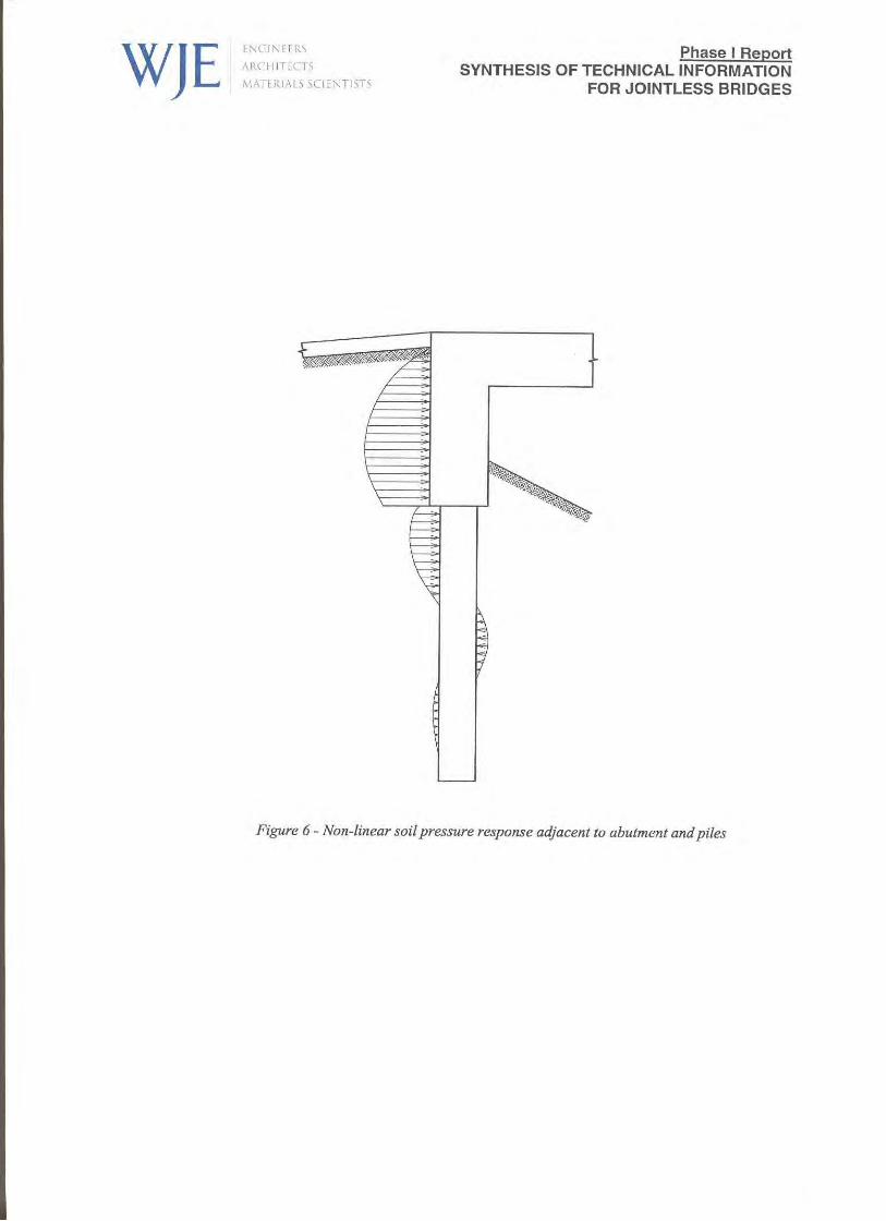


Phase I ReportSYNTHESIS OF TECHNICAL INFORMATION
FOR JOINTLESS BRIDGES
APPENDIX A

Appendix A
In order to develop the level of understanding of integral bridges it is necessary to examine somefundamental and advanced questions regarding their performance. A literature search is necessary in orderto address the following questions:
1. How does pile orientation affect rotation or translation of the integral abutments? Do integralabutments rotate or translate and what effect does compaction of backfill, pile size and orientationhave on the mechanism of movement? What positive and/or negative impacts can be expected byorienting piles about either the weak or strong axis? Should piles be aligned with the direction ofmovement or centerline of bearing?
2. Does a plastic hinge actually form within the pile or are the stresses transferred to other abutmentcomponents? Where are the stress concentrations localized? There are two prevalent methods used tomodel integral abutments, the elastic and inelastic methods. Which method is most widely used andwhy? Have there been any more recent design methods proposed or researched? Additionally, if aplastic hinge doesn't form within the pile why orient the piles about the weak axis? Is the formation ofa plastic hinge desired and if so is there a significant loss of pile capacity?
3. Is pre-excavation or pre-boring of holes for piling necessary? Only necessary for stiff soils? Doescurrent research offer any recommendations? If you pre-excavate, should the piles be backfilled withsand, peastone, or gravel? Does the material type matter if the material is recommended to be looselybackfilled with minimum compaction?
4. How does the compactness of the backfill affect the ability of the abutments to move? Should looselycompacted backfill be required or should the backfill be compacted to standard specifications? Willthe bridge simply "plow" the soil out of the way and develop a space for it to move on its own? Howdoes backfill type and compaction level effect the formation of the "bump" at the end of the bridge?
5. There are three common wingwall designs, flare, in-line, and u-wall configurations. HydraulicEngineers prefer the flared wingwalls while Structures Engineers prefer the u-wall configuration.What available research has addressed the performance of these various wingwall configurations, anddoes the u-wall configuration outperform the flared wingwalls or vice-versa? Does this issue evenmatter?
6. Realizing that current research limits the maximum abutment height to 4 meters, has research beenconducted that identifies the amount or degree of passive earth pressures developed not only behindthe integral abutments but also behind and on the bottom of the wingwalls? Has research beenconducted on materials or methods to limit the amount of passive pressure distributed to the abutmentby the backfill material?
7. Have integral abutments been analyzed using finite element analysis to map the stress concentrations(pile head, reinforcing steel, etc) as a result of thermal expansion/contraction? If so, are thereperformance monitoring results which support the documentation?
8. Research has been conducted by Iowa University that compares the actual deflection of the piles withthe results from finite element difference methods. However, these piles were jacked to specifieddisplacements rather than as a result of thermal expansion. Have piles been monitored on actualintegral bridge abutments under thermal expansion or contraction? Is this an area where more data isrequired or is this an area of redundancy?

Appendix A
9. Many states recommend using only compact sections. What does current research suggest regardingthe use of compact sections?
10. What are the current research findings with respect to approach slab design? What detail has provento be most effective in accommodating cyclic bridge movements?
11. What are the current research recommendations on skew limitations and curved girder bridges?
12. Regarding the use of the AASHTO interaction equation 10.54.2, should designers consider themoment due to live load rotation? Should impact be included in the live load reaction?
13. What are the effects of lateral displacement on the frictional capacity of the pile? Should piles forjointless bridges be designed as end-bearing only?
14. Approach slab performance has been an issue often discussed at Integral Abutment Committeemeetings. Have movements at the end of the bridge and approach slabs been monitored, if so havethese measurements been utilized to design effective and efficient design details? What are the mostrecent research recommendations regarding approach slab design details?
15. Have construction materials such as closed cell foam or lightweight fill material been evaluated forassisting in unrestricted movement of jointless bridges? If so, has this resulted in lower stressconcentrations within the piles, abutment, and/or approach slab? Has research been conductedregarding the use of a geotextile beneath approach slabs to facilitate the movement of the approachslab?
16. What research has been conducted to date evaluating the strains experienced in the deck concrete andsteel superstructure?
17. What are the known limitations of integral abutment bridges? Are there any documented failures ofintegral abutment bridges? What research, if any, has been conducted on the performance of jointlesssuperstructures on spread footings?
18. The different components of jointless bridges act together as a unit, what field measurements arenecessary to model the performance of this unit as a whole?
19. Has there been a study conducted to verify and track the amount of savings experienced, especiallymaintenance costs? Are savings in life cycle costs actually realized?
20. Are jointless bridges best served by providing an expansion detail at the end of the bridge or at theend of the approach slabs?
21 What temperature range is recommended for design purposes for calculating the anticipated thermaldeflection of both steel and concrete superstructures? Are the AASHTO recommendations overlyconservative? Is the determination of effective temperature in accordance with ASHRAE temperaturedata, as outlined by Ralph Oesterle of CTL Laboratories in his summary report to FHWA on Jointlessand Integral Abutment Bridges, valid for our region?

Phase I ReportSYNTHESIS OF TECHNICAL INFORMATION
FOR JOINTLESS BRIDGES
APPENDIX B

1
PERFORMANCE MONITORING OF JOINTLESS
BRIDGES
Phase I: Synthesis of Technical Information for Jointless Bridge Construction
VOLUME 1
TABLE OF CONTENTS
1. Lawver, A., French, C. and Shield, C. K.; “Field Performance of an Integral Abutment Bridge”; 1-19.
2. Loveall, C. L.; “Jointless Bridge Decks”; Civil Engineering/ASCE; Nov. 1985; 64-67.
3. “Integral Construction”; Synthesis of Highway Practice Report 141; NCMRP; 1989; 20-30.
4. Burke, M. P., Jr.; “Integral Bridges”; Transportation Research Record 1275; Committee on GeneralStructures; 53-61.
5. Burke, M. P., Jr.; “Integral Bridges: Attributes and Limitations”; Transportation Research Record1393; Committee on General Structures; 1-8.
6. Steel Bridges; American Iron & Steel Institute, Washington, D.C.; 1993; 1-6.
7. Xanthakos, P.; Theory and Design of Bridges; 1994; 1102-1107.
8. Xanthakos, P.; Bridge Substructure and Foundation Design; Prentice Hall; 1995; 503-507.
9. Wasserman, E. P. and Walker, J. H.; “Integral Abutments for Steel Bridges”; Highway StructuresDesign Handbook; Vol. 2, Chap. 5; American Iron and Steel Institute; 1996; 1-20.
10. David Densmore Letter and Biblio
11. “Design & Construction of Integral Bridges to the USA”; Concrete Bridge Development Group;1997; 1-3.
12. High Performance Steel Bridge Concepts, 1 page.
13. J. Muller detail, 1 page.
14. Section 10.27 of book. 15. Greifmann, L. F., Wolde-Tinsae, A. M., and Yang, P. S.; “Skewed Bridges with Integral Abutments”;
Transportation Research Record 903; Committee on General Structures; 64-72.
2
16. Jorgenson, J. L.; “Behavior of Abutment Piles in an Integral Abutment in Response to BridgeMovements”; Transportation Research Record 903; Committee on Foundations of Bridges and OtherStructures; 72-79.
17. Ng, C. W. W., Springman, S. M., and Norrish, A. R. M.; “Centrifuge Modeling of Spread-BaseIntegral Bridge Abutments”; Journal of Geotechnical and Geoenvironmental Engineering; 1998;376-388.
18. Wolde-Tinsae, A. M., Klinger, J. E., and White, E. J.; “Performance of Jointless Bridges”; Journal ofPerformance of Constructed Facilities; Vol. 2, No. 2; ASCE; 1988; 111-124.
19. Soltani, A. A. and Kukreti, A. R.; “Performance Evaluation of Integral Abutment Bridges”;Transportation Research Record 1371; Committee on General Structures; 17-25.
20. Elgaaly, M., Sanford, T. C., and Colby, C.; “Testing an Integral Steel Frame Bridge”; TransportationResearch Record 1371; Committee on General Structures; 75-82.
21. Sanford, T. C. and Elgaaly, M.; “Skew Effects on Backfill Pressures at Frame Bridge Abutments”;Field Performance of Structures and Nondestructive Evaluation of Subsurface Infrastructure,Transportation Research Record 1415; Committee on General Structures; 1993; 1-10.
22. Thippeswamy, H. K., Raju, P. R., and GangaRao, H. V. S.; “Parametric Study of Single-SpanJointless Steel Bridges”; Transportation Research Record 1460; Committee on Steel Bridges; 1994;25-36.
23. Lawver, A., French, C., and Shield, C. K.; “Field Performance of Integral Abutment Bridge”;Transportation Research Record 1740; Committee on General Structures; 2000; 108-117.
24. Seismic Design of Highway Bridge Foundations; Vol. 2; 1986; 131-140.
25. Greimann, L. and Wolde-Tinsae, A. M.; “Design Model For Piles in Jointless Bridges”; Journal ofStructural Engineering; Vol. 114, No. 6; ASCE; 1988; 1354-1371.
26. Abendroth, R. E. and Greimann, L. F.; “Rational Design Approach for Integral Abutment BridgePiles”; Transportation Research Record 1223; Committee on General Structures; 12-23.
27. Abendroth, R. E., Greimann, L. F., and Ebner, P. B.; “Abutment Pile Design for Jointless Bridges”;Journal of Structural Engineering; Vol. 115, No. 11; ASCE; 1989; 2914-2929.
28. Girton, D. D., Hawkinson, T. R., and Greimann, L. F.; “Validation of Design Recommendations forIntegral-Abutment Piles”; Journal of Structural Engineering; Vol. 117, No. 7; ASCE; 1991; 2117-2134.
29. Wasserman, E. P.; “Design of Integral Abutments for Jointless Bridges”; Structure; 2001; 24-33.
30. Greimann, L. F., Yang, P., and Wolde-Tinsae, A. M.; “Nonlinear Analysis of Integral AbutmentBridges”; Journal of Structural Engineering; Vol. 112, No. 10; ASCE; 1986; 2263-2280.
31. Dagher, H. J., Elgaaly, M., and Kankam, J.; “Analytical Investigation of Slab Bridges with IntegralWall Abutments”; Transportation Research Record 1319; Committee on Concrete Bridges; 115-125.
3
VOLUME 2
TABLE OF CONTENTS
1. Thippeswamy, H. K. and GangaRao, H. V. S.; “Analysis of In-Service Jointless Bridges”; Steel,Concrete, and Wood Bridges, Transportation Research Record 1476; Committee on GeneralStructures; 1995; 162-170.
2. Siros, K. A. and Spyrakos, C. C.; “Creep Analysis of Hybrid Integral Bridges”; Steel, Concrete, andWood Bridges, Transportation Research Record 1476; Committee on Dynamics and Field Testing onBridges; 1995; 147-154.
3. Kamel, M. R., Benak, J. V., Tadros, M. K., and Jamshidi, M.; “Application of Precast, PrestressedConcrete Piles in Integral Abutment Bridges”; Fourth International Bridge Engineering Conference;Vol. 2; Nebraska DOT, the Precast Concrete Associations of Nebraska, and the Center forInfrastructure Research Univ. of Nebraska; 1995; 146-157.
4. Faraji, S., Ting, J. M., Crovo, D. S., and Ernst, H.; “Nonlinear Analysis of Integral Bridges: Finite-Element Model”; Journal of Geotechnical and Geoenvironmental Engineering; 2001; 454-461.
5. Burke, M. P., Jr.; “Bridge Approach Pavements, Integral Bridges, and Cycle-Control Joints”;Transportation Research Record 1113; Committees on Sealants and Fillers for Joints and Cracks andon Pavement Maintenance; 1987; 54-65.
6. Hulsey, J. L. and Emanuel, J. H.; “Environmental Stresses in Flexibly Supported Bridges”; 262-270.
7. Wasserman, E. P.; “Jointless Bridge Decks”; Engineering Journal/American Institute of SteelConstruction; 1987.
8. “Section 3.6.12 Integral Abutments”; Illinois Bridge Manual; 1995; 182-190.
9. “Section 4 Integral Abutments”; New York Bridge Manual; 28-94.
10. “Design of Integral Abutments”; Maine Bridge Manual; 1997; 700(44)-701(1).
11. “Integral Abutment Bridges”; Connecticut Bridge Manual; 1998; 1-6.
12. “Section 3.9 Integral Abutment Bridges”; Mass Highway Bridge Manual; 1999; 35-50.
13. Burke, M. P., Jr.; “Semi-Integral Bridges: Movements and Forces”; Transportation Research Record1460; Committee on General Structures; 1-7.
14. Burke, M.P., Jr. and Gloyd, C.S.; “Emergence of Semi-Integral Bridges”, Transportation ResearchRecord 1594; Committee on General Structures; 1997; 179-186.
15. Thomas, M. E.; “Field Study of Integral Abutment Bridges”; 1999. (Abstract only.)
16. Sayers, B. H.; “Experimental and Analytical Study of Integral Abutment Bridges”; 2000. (Abstractonly.)
17. Abendroth, R. and Greimann, L. F.; “Testing of Integral Abutments HR-399”; Iowa Department ofTransportation, Iowa Highway Research Board. (Abstract only.)

4
18. Burke, M. P., Jr.; “Integral Bridge Design Is On The Rise”; Modern Steel Construction; AmericanInstitute of Steel Construction; 1990; 9-11.
19. Johnson, James M. Letter to all designers and consultants. 10 Mar. 1989.
20. Szabo, J. R. Letter to all design, operations, and district personnel, and consultants. 2 Nov. 1992.
21. Burke, M. P., Jr.; “The Design of Integral Concrete Bridges”; Concrete International; 1993; 37-42.
22. Alampalli, S. and Yannotti, A. P.; “In-Service Performance of Integral Bridges and Jointless Decks”;Structural Analysis and Design: Bridges, Culverts, and Pipes, Transportation Research Record 1624;Committee on General Structures; 1998; 1-7.
23. Burke, M. P., Jr.; “Cracking of Concrete Decks and Other Problems with Integral-Type Bridges”;Various Bridge Design Issues, Transportation Research Record 1688; Committee on GeneralStructures; 1999; 131-138.
24. Mourad, S. and Tabsh, S. W.; “Deck Slab Stresses in Integral Abutment Bridges; Journal of BridgeEngineering; Vol. 4, No. 2; ASCE; 1999; 125-130.
25. Dicleli, M.; “Simplified Model for Computer-Aided Analysis of Integral Bridges”; Journal of BridgeEngineering; Vol. 5, No. 3; ASCE; 2000; 240-248.
26. Caner, A. and Zia, P.; “Behavior and Design of Link Slabs for Jointless Bridge Decks”; PCI Journal;North Carolina DOT, Federal Highway Administration; 1998; 68-80.
27. Kamel, M. R., Benak, J. V., Tadros, M. K. and Jamshidi, M.; “Prestressed Concrete Piles in JointlessBridges”; PCI Journal; Nebraska Dept. of Roads, Pre-cast Concrete Association of Nebraska, and theCenter for Infrastructure Research, Univ. of Nebraska; 1996; 56-67.
28. Ndon, U. J. and Bergeson, K. L.; “Thermal Expansion of Concretes: Case Study in Iowa”; Journal ofMaterials in Civil Engineering; Vol. 7, No. 4; ASCE; 1995; 246-251.
29. Russell, H. G. and Gerken, L. J.; “Jointless Bridges – the Knowns and Unknowns”; ConcreteInternational; April 1994; 44-48.
30. Reid, R. A., Soupir, S. P., and Schaefer, V. R.; “Mitigation of Void Development Under BridgeApproach Slabs Using Rubber Tire Chips”; Recycled Materials in Geotechnical Applications;Vol. n79; South Dakota DOT; 1998; 37-50.
31. Nickerson, R. L.; “Jointless Steel Bridges Design and Retrofit”; Building An InternationalCommunity of Structural Engineers Structures Congress – Proceedings of the 14th StructuresCongress; Vol. 1; ASCE; 1996; 313-320.
VOLUME 3
TABLE OF CONTENTS

5
1. “Bridge Deck Joint Rehabilitation (Retrofit)”; FHWA Technical Advisory T5140.16; Mar. 26, 1980;6 pp.
2. “Integral, No-Joint Structures and Required Provisions for Movement”; FHWA Technical AdvisoryT5140.13; Jan. 28, 1980; 6 pp.
3. Maroney, B., Kutter, B., Romstad, K., Chai, Y. H., Vanderbilt, E.; “Interpretation of Large ScaleBridge Abutment Test Results; 10 pp.
4. Kunan, J. and Alampalli, S.; “Integral Abutment Bridges: Current Practice in United States andCanada”; Journal of Performance of Constructed Facilities; Vol. 14, No. 3; ASCE; Aug. 2000; 104-111.
5. Wood, D. M. and Nash, D.; “Earth Pressures on an Integral Bridge Abutment: A Numerical CaseStudy”; Soils and Foundations; Vol. 40, No. 6; Japanese Society of Soil Mechanics and FoundationEngineering; 2000; 23-38.
6. Amde, A. M., Chini, S. A., and Mafi, M.; “Model Study of H-piles Subjected to Combined Loading”;Geotechnical and Geological Engineering; Vol. 15, No. 4; Kluwer Academic Publishers; 1997; 343-355.
7. Koskinen, M.; “Soil-Structure-Interaction of Jointless Bridges on Piles”; Proceedings of theInternational Conference on Soil Mechanics and Foundation Engineering; Vol. 2; InternationalSociety for Soil Mechanics and Foundation Engineering; 1997; 1091-1096.
8. Springman, S. M., Norrish, A., and Wilkinson, K.; “A Device for Displacement-Controlled Actuationof an Integral Bridge Abutment”; Centrifuge – International Conference; International Society forSoil Mechanics and Foundation Engineering, Technical Committee on Centrifuge Testing, andNational University of Singapore; Dept of Civil Engineering; 1994; 163-168.
9. Napier, C. S, Jr., McKeel, W. T., Jr., and Sprinkel, M. M.; “Bridging the Centuries: MovingVirginia’s Bridge Program Into the 21st Century”; Public Roads; Sept./Oct. 1998; 22-29.
10. Hanshan, D., Dajun, D., Jian, Y., and Wenji, H.; “Overview of a Jointless Concrete Ring SlabBridge”; Concrete International; Vol. 20; Dec. 1998; 32-33.
11. Mourad, S. and Tabsh, S. W.; “Pile Forces in Integral Abutment Bridges Subjected to Truck Loads”;Transportation Research Record 1633; Committee on Foundations of Bridges and Other Structures;1998; 77-83.
12. Superstructure/Substructure Joint Details; Federal Highway Administration, Nebraska Dept. ofRoads, the Center for Infrastructure Research, and the Univ. of Nebraska – Lincoln; Sept. 1999;176 pp.
13. Arsoy, S., Barker, R. M., and Duncan, J. M.; The Behavior of Integral Abutment Bridges; VirginiaTransportation Research Council; Nov. 1999; 33 pp.
14. Van Lund, J. A. and Brecto, B. B.; “Jointless Bridges and Bridge Deck Joints in Washington State”;Transportation Research Record 1688; Committee on General Structures; 1999; 116-123.
6
15. Wolde-Tinsae, A. M. and Klinger, J. E.; “Integral Abutment Bridge Design and Construction”; StateHighway Administration Research Report; Maryland DOT State Highway Administration; 1987;71 pp.
16. Weintraut, S. F.; “Jointless Bridges”; Purdue University Course CE 672; 1993.
17. Crovo, D. S.; “The Massachusetts Experience with Jointless Abutment Bridges”; 32-39.
18. Mistry, V. C.; “Integral Abutment and Jointless Bridges”.
19. Caltrans Memo to Designers 5-1; Oct. 1992; 1-8.
20. Caltrans Memo to Designers 5-2; Oct. 1992; 1-2.
21. Caltrans Memo to Designers 5-3; Dec. 1992; 1-3.
22. Caltrans Bridge Design Details; June 1990.
23. Caltrans Bridge Design Details; Nov. 1992.
24. Caltrans Bridge Design Aids; Jan. 1988; 1-6.
25. Report from website: http://business.fortunecity.com/kerkorian/666/integral/integral.html
26. Nielson, R. J. and Schmeckpeper, E. R.; “Consistent Design of Integral Abutment Bridges”; 17 pp.
VOLUME 4
TABLE OF CONTENTS
1. Thomas, M. E.; “Field Study of Integral Abutment Bridges”; Iowa State University Thesis; 1999;128 pp.
2. Sayers, B. H.; “Experimental and Analystical Study of Integral-Abutment Bridges”; Iowa StateUniversity Thesis; 2000; 259 pp.
VOLUME 5
TABLE OF CONTENTS
1. Flores, D. I.; “An Evaluation of Integral Abutment Behavior”; University of Washington Thesis;1994; 157 pp.
2. Metzger, A. T.; “Measurement of the Abutment Forces of a Skewed Semi-Integral Bridge as a Resultof Ambient Temperature Change”; Ohio University Thesis; 1995; 214 pp.

7
3. Franco, J.M.; “Design and Field Testing of Jointless Bridges”; West Virginia University Thesis;1999; 209 pp.; published on the internet at http://etd.wvu.edu/ETDS/E713/Thesis.PDF
4. Horvath, J.S.; “Integral Abutment Bridges: Problems and Innovative Solutions Using EPS Geofoamand Other Geosynthetics”; Manhattan College Research Report No. CE/GE-00-2; Manhattan CollegeSchool of Engineering, Civil Engineering Department; New York; 2000