synthesis, properties and applications of helical carbon nanotubes
TRANSCRIPT
This article was downloaded by: [University of Auckland Library]On: 15 October 2014, At: 12:43Publisher: Taylor & FrancisInforma Ltd Registered in England and Wales Registered Number: 1072954Registered office: Mortimer House, 37-41 Mortimer Street, London W1T 3JH,UK
Fullerenes, Nanotubes andCarbon NanostructuresPublication details, including instructions forauthors and subscription information:http://www.tandfonline.com/loi/lfnn20
Synthesis, Properties andApplications of Helical CarbonNanotubesA. Szabó a , A. Fonseca a , J. B. Nagy a , A. Volodin b
, C. Van Haesendonck b , L. P. Biró c & J.‐F. Colomerc
a Facultés Universitaires Notre Dame de la Paix ,Namur, Belgiumb Laboratorium voor Vaste‐Stoffysica enMagnetisme , Katholieke Universiteit Leuven ,Leuven, Belgiumc Research Institute for Technical Physics andMaterials Science , Budapest, HungaryPublished online: 06 Feb 2007.
To cite this article: A. Szabó , A. Fonseca , J. B. Nagy , A. Volodin , C. VanHaesendonck , L. P. Biró & J.‐F. Colomer (2005) Synthesis, Properties and Applicationsof Helical Carbon Nanotubes, Fullerenes, Nanotubes and Carbon Nanostructures,13:S1, 139-146, DOI: 10.1081/FST-200039237
To link to this article: http://dx.doi.org/10.1081/FST-200039237
PLEASE SCROLL DOWN FOR ARTICLE
Taylor & Francis makes every effort to ensure the accuracy of all theinformation (the “Content”) contained in the publications on our platform.However, Taylor & Francis, our agents, and our licensors make norepresentations or warranties whatsoever as to the accuracy, completeness,or suitability for any purpose of the Content. Any opinions and views

expressed in this publication are the opinions and views of the authors, andare not the views of or endorsed by Taylor & Francis. The accuracy of theContent should not be relied upon and should be independently verified withprimary sources of information. Taylor and Francis shall not be liable for anylosses, actions, claims, proceedings, demands, costs, expenses, damages,and other liabilities whatsoever or howsoever caused arising directly orindirectly in connection with, in relation to or arising out of the use of theContent.
This article may be used for research, teaching, and private study purposes.Any substantial or systematic reproduction, redistribution, reselling, loan,sub-licensing, systematic supply, or distribution in any form to anyone isexpressly forbidden. Terms & Conditions of access and use can be found athttp://www.tandfonline.com/page/terms-and-conditions
Dow
nloa
ded
by [
Uni
vers
ity o
f A
uckl
and
Lib
rary
] at
12:
43 1
5 O
ctob
er 2
014
Synthesis, Properties and Applications ofHelical Carbon Nanotubes
A. Szabo, A. Fonseca, and J. B. Nagy
Facultes Universitaires Notre Dame de la Paix, Namur, Belgium
A. Volodin and C. Van Haesendonck
Laboratorium voor Vaste-Stoffysica en Magnetisme, Katholieke
Universiteit Leuven, Leuven, Belgium
L. P. Biro and J.-F. Colomer
Research Institute for Technical Physics and Materials Science,
Budapest, Hungary
Abstract: Helical carbon nanotubes were produced on silica-supported Co catalysts by
chemical vapour decomposition of acetylene. Coiled nanotubes were examined. They
have been found to be of various shapes, diameter, and pitch. Some of them are
extremely long, up to 5mm, with regular helices. The average outer diameter of coils are
about 30–50 nm, the pitch is in the range 50–200 nm and the length about 1–1.4mm.
The helix-shaped windings of the helical carbon nanotubes reveal characteristic mechan-
ical resonances,which are determined by the elastic modulus,mass, shape, and dimensions.
Keywords: Carbon nanotubes, chemical vapor deposition, helices, supported catalysts
INTRODUCTION
Helical carbon nanotubes were predicted by Dunlap (1) and Ihara et al. (2) The
coiling of the proposed structures originated from the regular insertion of
pentagons and heptagons in the hexagonal honeycomb network.
Address correspondence to A. Szabo, Facultes Universitaires Notre Dame de la
Paix, 61 Rue de Bruxelles, Namur B-5000, Belgium. E-mail: antonia.fonseca@
fundp.ac.be
Fullerenes, Nanotubes, and Carbon Nanostructures, 13: 139–146, 2005
Copyright # Taylor & Francis, Inc.
ISSN 1536-383X print/1536-4046 online
DOI: 10.1081/FST-200039237
Dow
nloa
ded
by [
Uni
vers
ity o
f A
uckl
and
Lib
rary
] at
12:
43 1
5 O
ctob
er 2
014

Relatively large amounts of curved and coiled nanotubes were produced
by catalytic vapour decomposition of hydrocarbon. Their interesting, unusual,
and various shapes stimulated several studies on the modelling of the coiling
mechanism (3, 4). Recently Biro et al. (4) showed that specific wrappings
of the structures with nonhexagonal and hexagonal rings lead to a new
varieties of toroidal, coiled, screwlike, and pearl-necklace-like carbon nano-
architectures. The pentagons and heptagons are important parts of these struc-
tures. Their very specific arrangement is the basis for the formation of regular
helical coils.
The helical carbon nanotubes are described by the coil diameter and the
pitch. These nanotubes could be used in composites because they would be
better anchored in their embedding matrix than straight nanotubes. Their
shape would favour a better load transfer to the matrix than in the case of
straight tubes, and possibly easier infiltration. They could be attractive
objects for nano-electro-mechanical devices, because of their special electri-
cal and mechanical properties (5).
In present work we report the synthesis of coiled carbon nanotubes on
silica-supported cobalt catalysts produced by catalytic vapour decomposi-
tion of acetylene. We were interested in the influence of the catalyst
preparation methods and in the influence of metal loading on the quality of
carbon deposit and the formation of coiled nanotubes.
EXPERIMENTAL
Preparation Methods of the Catalysts
Ion-Adsorption Precipitation Method
The appropriate amount of Co(CH3COO)2. 4H2O (Aldrich) was dissolved in
distilled water; 3 g of silicagel (Merck part. diam. 15–40mm) as added to the
solution under stirring. The mixture was stirred about 20 min. The pH was
controlled and adjusted to pH 9 using ammonia solution (Vel). After 48 hr
the pH of the as-prepared mixture was controlled and set again to 9, just
before the filtration. Then the precipitate was washed with distilled water,
dried at 1208C overnight, and ground.
Sol–Gel Method
This technique is based on the hydrolysis of tetraethoxysilane (TEOS-Acros)
in an acidic or basic environment; 10 ml of ethanol (Fluka), 10 ml of TEOS
and 15 ml of 1.5 M solution of Co(CH3COO)2. 4H2O (Aldrich) were mixed.
The mixture was stirred for 20 min. A few drops of conc. HF (Vel) were
added to promote the reaction and the stirring was continued for another
A. Szabo et al.140
Dow
nloa
ded
by [
Uni
vers
ity o
f A
uckl
and
Lib
rary
] at
12:
43 1
5 O
ctob
er 2
014
20 min. The as-prepared gel was dried at 608C overnight, then ground and
calcined for 1 hr at 4508C in air.
The carbon nonotube growth reactions were carried out in a fixed bed
flow reactor using acetylene as carbon source and N2 as inert gas; 1 g of
catalyst was introduced to the reactor at 7008C for 30 min. Gas flow rate
was 30 ml/min of C2H2 in 300 ml/min of N2. TEM (Tecnai, Philips), SEM
(XL Series, Philips), HRTEM were used to characterize the products. The
carbon deposit was calculated as follows:
Carbon deposit ð%Þ ¼ 100mtot � mcat
mcat
;
where mtot is the mass of total product and mcat is the mass of corrected
catalyst.
RESULTS AND DISCUSSION
The first part of our results is summarised in Table 1. Here we compare the
products obtained on the catalyst prepared by Method (1) with different Co
loadings (2.5–12.5 wt.%). The results are based on the TEM microscope
observations.
In the case of 2.5 wt.% metal content, the product was poor in carbon
nanotubes and coils. Mainly amorphous carbon and catalyst particles were
found in the samples. In the other cases, the catalysts had a good activity.
The surface of the catalyst was totally covered by CNTs. We observed
several morphologies of nanotubes such as tubes differently curved, helical
tubes, springs, and spirals. The coiled tubes were examined. Generally, the
pitch varied from 50–200 nm and the coil diameter was in the range of 50–
150 nm. We observed several coils with length up to 5mm. These long coils
were usually intercoiled with themselves, and in some cases they formed inter-
esting structures. The total carbon deposit was about 40–60% and the amount
of coiled nanotubes was approximately 5% (Fig. 1).
Most of the tubes (Fig. 1) do not contain metal particles and their tips are
open. In some cases we observed coils that, after some coiling, continue as
Table 1. Carbon deposit and quality, for catalysts prepared by Method (1)
Wt.% of Co 2.5 5 10 12.5
Coiled tubes þ þ þ þ þ þ þ þ þ þ
Other tubes þ þ þ þ þ þ þ þ þ þ þ þ þ þ
Carbon deposit (%) 40 50 60 60
% of coils 0.5 15 10 6
Helical Carbon Nanotubes 141
Dow
nloa
ded
by [
Uni
vers
ity o
f A
uckl
and
Lib
rary
] at
12:
43 1
5 O
ctob
er 2
014
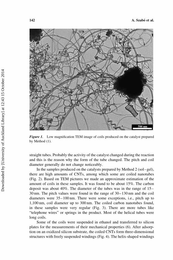
straight tubes. Probably the activity of the catalyst changed during the reaction
and this is the reason why the form of the tube changed. The pitch and coil
diameter generally do not change noticeably.
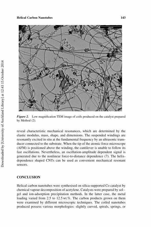
In the samples produced on the catalysts prepared by Method 2 (sol–gel),
there are high amounts of CNTs, among which some are coiled nanotubes
(Fig. 2). Based on TEM pictures we made an approximate estimation of the
amount of coils in these samples. It was found to be about 15%. The carbon
deposit was about 40%. The diameter of the tubes was in the range of 15–
30 nm. The pitch values were found in the range of 30–130 nm and the coil
diameters were 35–100 nm. There were some exceptions, i.e., pitch up to
1,100 nm, coil diameter up to 300 nm. The coiled carbon nanotubes found,
in these samples were very regular (Fig. 3). There are more tubes like
“telephone wires” or springs in the product. Most of the helical tubes were
long coils.
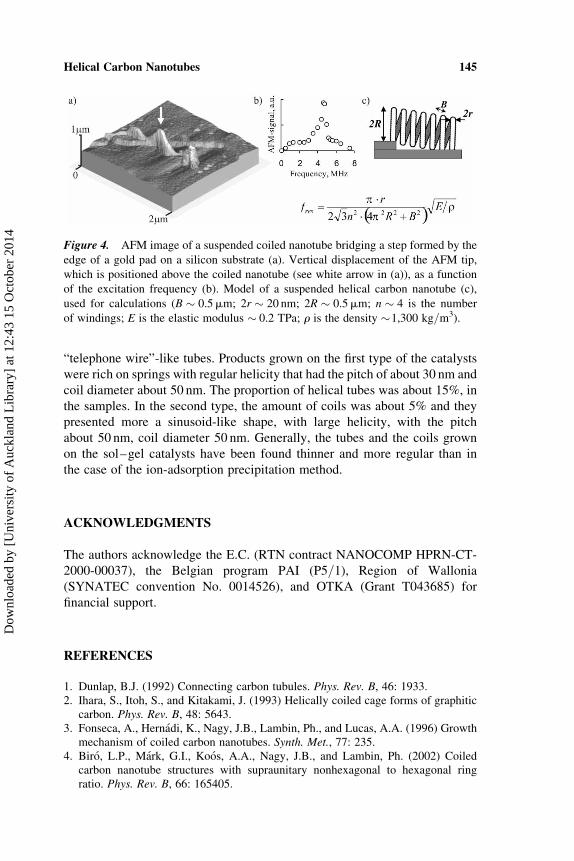
Some of the coils were suspended in ethanol and transferred to silicon
plates for the measurements of their mechanical properties (6). After adsorp-
tion on an oxidized silicon substrate, the coiled CNTs form three-dimensional
structures with freely suspended windings (Fig. 4). The helix-shaped windings
Figure 1. Low magnification TEM image of coils produced on the catalyst prepared
by Method (1).
A. Szabo et al.142
Dow
nloa
ded
by [
Uni
vers
ity o
f A
uckl
and
Lib
rary
] at
12:
43 1
5 O
ctob
er 2
014
reveal characteristic mechanical resonances, which are determined by the
elastic modulus, mass, shape, and dimensions. The suspended windings are
resonantly excited in situ at the fundamental frequency by an ultrasonic trans-
ducer connected to the substrate. When the tip of the atomic force microscope
(AFM) is positioned above the winding, the cantilever is unable to follow its
fast oscillations. Nevertheless, an oscillation-amplitude dependent signal is
generated due to the nonlinear force-to-distance dependence (7). The helix-
dependence shaped CNTs can be used as convenient mechanical resonant
sensors.
CONCLUSION
Helical carbon nanotubes were synthesised on silica-supported Co catalyst by
chemical vapour decomposition of acetylene. Catalysts were prepared by sol–
gel and ion-adsorption precipitation methods. In the latter case, the metal
loading varied from 2.5 to 12.5 wt.%. The carbon products grown on them
were examined by different microscopic techniques. The coiled nanotubes
produced possess various morphologies: slightly curved, spirals, springs, or
Figure 2. Low magnification TEM image of coils produced on the catalyst prepared
by Method (2).
Helical Carbon Nanotubes 143
Dow
nloa
ded
by [
Uni
vers
ity o
f A
uckl
and
Lib
rary
] at
12:
43 1
5 O
ctob
er 2
014
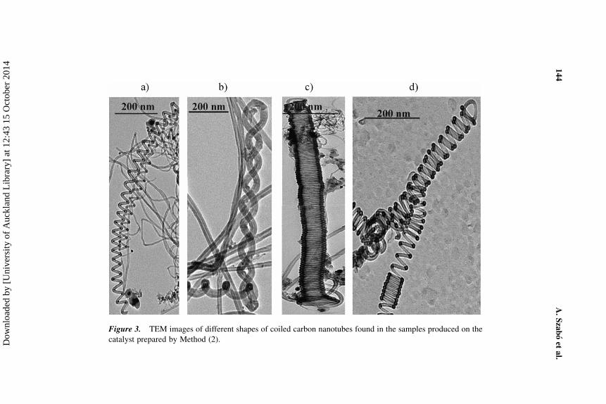
Figure 3. TEM images of different shapes of coiled carbon nanotubes found in the samples produced on the
catalyst prepared by Method (2).
A.Szaboet
al.
144
Dow
nloa
ded
by [
Uni
vers
ity o
f A
uckl
and
Lib
rary
] at
12:
43 1
5 O
ctob
er 2
014
“telephone wire”-like tubes. Products grown on the first type of the catalysts
were rich on springs with regular helicity that had the pitch of about 30 nm and
coil diameter about 50 nm. The proportion of helical tubes was about 15%, in
the samples. In the second type, the amount of coils was about 5% and they
presented more a sinusoid-like shape, with large helicity, with the pitch
about 50 nm, coil diameter 50 nm. Generally, the tubes and the coils grown
on the sol–gel catalysts have been found thinner and more regular than in
the case of the ion-adsorption precipitation method.
ACKNOWLEDGMENTS
The authors acknowledge the E.C. (RTN contract NANOCOMP HPRN-CT-
2000-00037), the Belgian program PAI (P5/1), Region of Wallonia
(SYNATEC convention No. 0014526), and OTKA (Grant T043685) for
financial support.
REFERENCES
1. Dunlap, B.J. (1992) Connecting carbon tubules. Phys. Rev. B, 46: 1933.2. Ihara, S., Itoh, S., and Kitakami, J. (1993) Helically coiled cage forms of graphitic
carbon. Phys. Rev. B, 48: 5643.3. Fonseca, A., Hernadi, K., Nagy, J.B., Lambin, Ph., and Lucas, A.A. (1996) Growth
mechanism of coiled carbon nanotubes. Synth. Met., 77: 235.4. Biro, L.P., Mark, G.I., Koos, A.A., Nagy, J.B., and Lambin, Ph. (2002) Coiled
carbon nanotube structures with supraunitary nonhexagonal to hexagonal ringratio. Phys. Rev. B, 66: 165405.
Figure 4. AFM image of a suspended coiled nanotube bridging a step formed by the
edge of a gold pad on a silicon substrate (a). Vertical displacement of the AFM tip,
which is positioned above the coiled nanotube (see white arrow in (a)), as a function
of the excitation frequency (b). Model of a suspended helical carbon nanotube (c),
used for calculations (B � 0.5mm; 2r � 20 nm; 2R � 0.5mm; n � 4 is the number
of windings; E is the elastic modulus � 0.2 TPa; r is the density �1,300 kg/m3).
Helical Carbon Nanotubes 145
Dow
nloa
ded
by [
Uni
vers
ity o
f A
uckl
and
Lib
rary
] at
12:
43 1
5 O
ctob
er 2
014
5. Ahlskog, M., Seynaeve, E., Vullers, R.J.M., Van Haesendonck, C., Fonseca, A.,Hernadi, K., Volodin, J.A., and Nagy, J.B. (1999) Ring formations from catalyti-cally synthesized carbon nanotubes. Chem. Phys. Lett., 300: 202.
6. Volodin, A., Ahlskog, M., Seynaeve, E., Van Haesendonck, C., Fonseca, A., andNagy, J.B. (2000) Imaging the elastic properties of coiled carbon nanotubes withatomic force microscopy. Phys. Rev. Lett., 84: 3342.
7. Volodin, A., Van Haesendonck, C., Tarkiainen, R., Ahlskog, M., Fonseca, A., andNagy, J.B. (2001) AFM detection of the mechanical resonances of coiled carbonnanotubes. Appl. Phys. A., 72: S75.
A. Szabo et al.146
Dow
nloa
ded
by [
Uni
vers
ity o
f A
uckl
and
Lib
rary
] at
12:
43 1
5 O
ctob
er 2
014