system 3 pro biodex
TRANSCRIPT
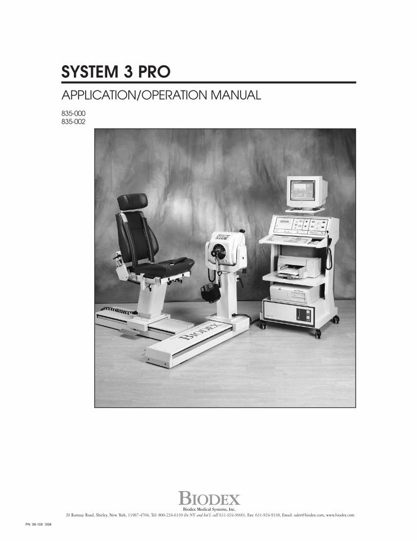
SYSTEM 3 PRO APPLICATION/OPERATION MANUAL835-000835-002
BIODEXBiodex Medical Systems, Inc.
20 Ramsay Road, Shirley, New York, 11967-4704, Tel: 800-224-6339 (In NY and Int’l, call 631-924-9000), Fax: 631-924-9338, Email: [email protected], www.biodex.com
FN: 06-159 3/06
— II —
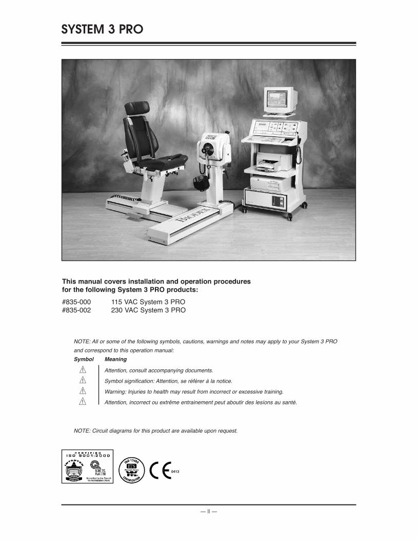
This manual covers installation and operation procedures
for the following System 3 PRO products:
#835-000 115 VAC System 3 PRO#835-002 230 VAC System 3 PRO
SYSTEM 3 PRO
0413
NOTE: All or some of the following symbols, cautions, warnings and notes may apply to your System 3 PRO
and correspond to this operation manual:
Symbol Meaning
Attention, consult accompanying documents.
Symbol signification: Attention, se référer à la notice.
Warning: Injuries to health may result from incorrect or excessive training.
Attention, incorrect ou extrême entrainement peut aboutir des lesíons au santé.
NOTE: Circuit diagrams for this product are available upon request.
!
!
!
!
— III — TABLE OF CONTENTS
INTRODUCTION ..................................................................................................................................IV
BEFORE PROCEEDING ..........................................................................................................................V
1. CONTROLS AND ADJUSTMENTS ..............................................................................................1-1Dynamometer....................................................................................................................................1-1Positioning Chair ..............................................................................................................................1-4Seat Back Brace..................................................................................................................................1-6The Control Panel ............................................................................................................................1-7Controller ........................................................................................................................................1-11Dynamometer Attachments ..........................................................................................................1-12The Combination Ankle Attachment (for All Ankle Patterns and Knee: Tibial Internal/External Rotation) ..........................................................................................................1-14
2. OPERATION ........................................................................................................................................2-1Considerations for Safe Operation of Your Biodex System........................................................2-1General Operating Instructions (Mechanical) ..............................................................................2-3The Setup Mode (Sample Procedure) ............................................................................................2-4The Isokinetic Mode (Sample Procedure) ....................................................................................2-6The Passive Mode (Sample Procedure) ........................................................................................2-8The Isometric Mode (Sample Procedure)....................................................................................2-10The Isotonic Mode (Sample Procedure) ......................................................................................2-11The Reactive Eccentric Mode (Sample Procedure) ....................................................................2-13Additional Considerations ............................................................................................................2-15Proper Testing Technique ..............................................................................................................2-16
3. SETUP AND POSITIONING FOR STANDARD TEST AND EXERCISE PATTERNS ......3-1Knee Extension/Flexion ..................................................................................................................3-2Ankle Plantar/Dorsiflexion (Seated) ............................................................................................3-6Ankle Inversion/Eversion ............................................................................................................3-10Hip Abduction/Adduction (Lying on Side) ..............................................................................3-13Hip Extension/Flexion (Supine) ..................................................................................................3-16Shoulder Extension/Flexion (Seated)..........................................................................................3-19Shoulder Abduction/Adduction (Seated) ..................................................................................3-22Shoulder Internal/External Rot. in Modified Neutral Position ..............................................3-25Shoulder Internal/External Rot. in 90-Degrees of Abduction ................................................3-28Shoulder Diagonal (Seated) ..........................................................................................................3-31Shoulder Diagonal (Standing) ......................................................................................................3-34Elbow Extension/Flexion ..............................................................................................................3-37Forearm Pronation/Supination ....................................................................................................3-40Wrist Extension/Flexion ................................................................................................................3-43Wrist Radial/Ulnar Deviation ......................................................................................................3-46
4. USING ThE OPTIONAL CLOSED ChAIN ATTAChMENT ..................................................4-1Parts & Components ........................................................................................................................4-1Introduction ......................................................................................................................................4-1Setup Procedure ................................................................................................................................4-2Upper Extremity Exercise................................................................................................................4-4Lower Extremity Exercise................................................................................................................4-4Applications ......................................................................................................................................4-5Technical Information ......................................................................................................................4-8
5. REFERENCE MATERIALS................................................................................................................5-1Suggested Test Speeds......................................................................................................................5-1Legal Precedents ..............................................................................................................................5-2Biodex Data Admitted as Medical Evidence in Court ................................................................5-2
6. APPENDICES ......................................................................................................................................6-1EMG/Analog Signal Access Interface ..........................................................................................6-1Maintenance ......................................................................................................................................6-3System Specifications ......................................................................................................................6-4General Product Warranty ..............................................................................................................6-6
TABLE OF CONTENTS
Congratulations, you’ve made an excellent choice!
By selecting the Biodex System you have acquired the most advanced, versatile and reliable tech-nology ever developed for testing and rehabilitation of the human musculoskeletal system.You’ve also joined the Biodex team of satisfied customers who benefit from unsurpassed producteducation, customer service, promotional and clinical support.
With your new system, you can offer testing and rehabilitation services for the knee, ankle and hipplus the shoulder, elbow, forearm and wrist. Modes of operation for exercise and testing includeIsokinetic, Passive, Isometric, Isotonic and Reactive Eccentric. What’s more, you’ll be able to testand exercise over the broadest range of speeds available today. If you add the Back, Lift and WorkSimulation options, your Biodex System is transformed into a comprehensive clinic.
You’ll also appreciate the Windows-based Biodex Advantage Software package that comes withyour system. Our patient database prompts quick and easy retrieval of patient information whileWindows flexibility makes protocol selection and patient setups a snap. The wide variety of out-put reports allows numeric and graphic information to be printed in a number of different for-mats. Third party payers and referring physicians receive information that is complete but notoverwhelming.
Biofeedback is provided by the high resolution color graphics monitor to encourage patient com-pliance with exercise protocols.
The versatility of the Biodex System facilitates effective treatment of a broad range of patients andpathologies. The future certainly looks bright for you and your patients! Thank you for allowingBiodex Medical Systems, Inc., to be a part of it.
NOTE: PRODUCT ENHANCEMENTS AND MODIFICATIONSDue to on-going product enhancements and modifications, the Biodex System you have purchasedmay differ slightly from the system depicted in the photographs and illustrations used in this manual.
NOTE: LEvELINg PAD INSTALLATION INSTRUCTIONSShipped with each unit are six leveling pads. These can be used to eliminate any excessive rockingof the Biodex T-bases.
Once the T-bases have been assembled and all bolts have been tightened, slide the dynamometer toone side and note if there is any rocking of the T-bases. If noted, move dynamometer to other side ofthe T-base and repeat. Place the necessary amount of leveling pads under the ends of the T-base toeliminate any excessive motion.
Use caution when lifting the T-base to place the pads underneath.
If you have any questions, contact Biodex service at (800) 224-6339, in NY and Int’l, (631) 924-9000.
INTRODUCTION
INTRODUCTION — IV —
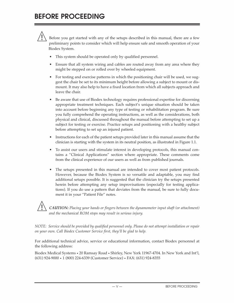
Before you get started with any of the setups described in this manual, there are a fewpreliminary points to consider which will help ensure safe and smooth operation of yourBiodex System.
• This system should be operated only by qualified personnel.
• Ensure that all system wiring and cables are routed away from any area where theymight be stepped on or rolled over by wheeled equipment.
• For testing and exercise patterns in which the positioning chair will be used, we sug-gest the chair be set to its minimum height before allowing a subject to mount or dis-mount. It may also help to have a fixed location from which all subjects approach andleave the chair.
• Be aware that use of Biodex technology requires professional expertise for discerningappropriate treatment techniques. Each subject’s unique situation should be takeninto account before beginning any type of testing or rehabilitation program. Be sureyou fully comprehend the operating instructions, as well as the considerations, bothphysical and clinical, discussed throughout the manual before attempting to set up asubject for testing or exercise. Practice setups and positioning with a healthy subjectbefore attempting to set up an injured patient.
• Instructions for each of the patient setups provided later in this manual assume that theclinician is starting with the system in its neutral position, as illustrated in Figure 1.1.
• To assist our users and stimulate interest in developing protocols, this manual con-tains a ”Clinical Applications” section where appropriate. These comments comefrom the clinical experience of our users as well as from published journals.
• The setups presented in this manual are intended to cover most patient protocols.However, because the Biodex System is so versatile and adaptable, you may findadditional setups possible. It is suggested that the clinician try the setups presentedherein before attempting any setup improvisations (especially for testing applica-tions). If you do use a pattern that deviates from the manual, be sure to fully docu-ment it in your “Patient File” notes.
CAUTION: Placing your hands or fingers between the dynamometer input shaft (or attachment)
and the mechanical ROM stops may result in serious injury.
NOTE: Service should be provided by qualified personnel only. Please do not attempt installation or repairon your own. Call Biodex Customer Service first, they’ll be glad to help.
For additional technical advice, service or educational information, contact Biodex personnel atthe following address:
Biodex Medical Systems • 20 Ramsay Road • Shirley, New York 11967-4704. In New York and Int’l,(631) 924-9000 • 1 (800) 224-6339 (Customer Service) • FAX: (631) 924-8355
!
!
BEFORE PROCEEDINGTABLE OF CONTENTS
— V — BEFORE PROCEEDING
Avant d'appliquer les montages décrits dans cette notice, plusieurs consignes aideront àobtenir une utilisation sûre et facile de votre système BIODEX.
• Utilisation de ce système doit être limité au personnel qui a les qualités requises.
• Vérifier que tous les câbles et cordons suivent un trajet qui ne traverse ni un zone detravail ni une zone de déplacement des pièces mobiles.
• Pour les mouvements d'examen ou d'entraînement nécessitant une chaise accessoire,régler la chaise accessorie à sa position la plus basse avant de faire monter ou descendre le patient. Dans certains cas un accèss fixe à la chiase peut être utile.
• La technologie BIODEX nécessite une expertise professionelle pour choisir la technique thérapeutique appropriée. La situation de chaque patient doit déterminer le programme de rééducation. S'assurer de bien comprendre la présente notice ainsi que le contexte clinique associé avant d'applier la technologie pour l'examen ou la réédcation d'un patient. S'entraîner à faire des montages avec des sujets sains avant d'enfaire avec un patient.
• Le indications pour les montages spécifiques fournies dans les pages qui suivent pren-nent comme point de départ le système dans sa position neutre montré à l'image 1.1.
• Pour aider nos clients à développer leurs protocoles, cette notice contient certains passages sur des applications cliniques. Ces textes tiennent compte de l'expérience desutilisateurs BIODEX et des informations publiécs mais ne puevent pas remplacer le jugement clinique.
• Les montages présents dans la présente notice couvrent la plupart des protocoles. Toutéfois les nombreuses possibilités du système BIODEX permettent d'autres montages. On conscille d'utiliser les montages de la notice avant de réaliser des improvisations, surtout pour les applications d'examen. Si vous utilisez un mouvement différent de ceux trait´s, notez-en les détails dans votre dossier patient.
ATTENTION: Placer vos mains ou doigts entre le dynamometer données (ou attachement) et le
mécanique ROM arrêts peut résulter dans sérieux blessure.!
!
AVANT TOUTE APPLICATION
BEFORE PROCEEDING — VI —
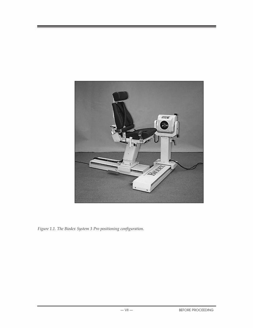
Figure 1.1. The Biodex System 3 Pro positioning configuration.
X
— VII — BEFORE PROCEEDING
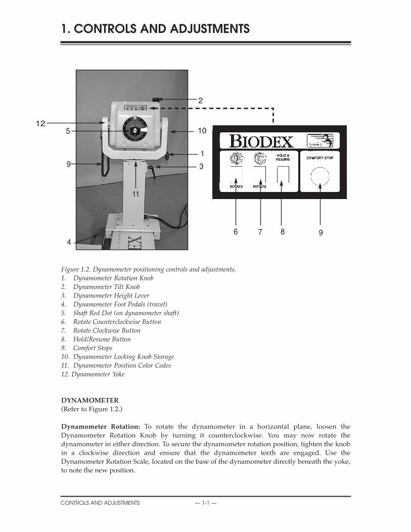
Figure 1.2. Dynamometer positioning controls and adjustments. 1. Dynamometer Rotation Knob 2. Dynamometer Tilt Knob3. Dynamometer Height Lever4. Dynamometer Foot Pedals (travel)5. Shaft Red Dot (on dynamometer shaft)6. Rotate Counterclockwise Button7. Rotate Clockwise Button8. Hold/Resume Button9. Comfort Stops10. Dynamometer Locking Knob Storage11. Dynamometer Position Color Codes12. Dynamometer Yoke
DYNAMOMETER
(Refer to Figure 1.2.)
Dynamometer Rotation: To rotate the dynamometer in a horizontal plane, loosen theDynamometer Rotation Knob by turning it counterclockwise. You may now rotate thedynamometer in either direction. To secure the dynamometer rotation position, tighten the knobin a clockwise direction and ensure that the dynamometer teeth are engaged. Use theDynamometer Rotation Scale, located on the base of the dynamometer directly beneath the yoke,to note the new position.
1. CONTROLS AND ADJUSTMENTS
CONTROLS AND ADJUSTMENTS — 1-1 —
2
10
1
3
6 7 8 9
512
4
9
11

Dynamometer Tilt: Permits rotation of the dynamometer on a vertical plane allowing the shaftaxis to tilt upward or downward from the horizontal position. To tilt the dynamometer, supportthe dynamometer with one hand. With the other hand, loosen the Dynamometer Tilt Knob in acounterclockwise direction. You can now gently push or pull the dynamometer to the desiredposition. Tighten the knob firmly in a clockwise direction, and ensure that the dynamometer teethare engaged, to secure the dynamometer in place. Use the Dynamometer Tilt Scale (located on theyoke) to note the new dynamometer tilt position.
Dynamometer height: The dynamometer can be raised or lowered over a range of 14”. Loosenthe Dynamometer Height Handle by turning it counterclockwise and simply apply hand pressureto the top or underside of the dynamometer to respectively raise or lower it. Retighten the handleto lock the dynamometer in position. Use the Dynamometer Height Scale, located on thedynamometer mounting post, to note the new dynamometer height.
NOTE: The weight of the dynamometer is counterbalanced by a pneumatic assembly in the mounting post.When the locking handle is loosened, the dynamometer may tend to gently rise or fall, dependingon the weight of attachments affixed to the dynamometer shaft. After proper height is established,always secure the locking handle.
Dynamometer Travel: The dynamometer Foot Pedals allow the dynamometer to move along thetravel in a horizontal plane left or right of the positioning chair. To move the dynamometer, pressdown on either foot pedal and slide the dynamometer to the desired location. Release the footpedal to lock the dynamometer in place. To ensure stability, check that the dynamometer is fullylocked in a detent (i.e., try to shake the dynamometer). Use the Dynamometer Position Scale onthe travel to note position.
Shaft Red Dot (dynamometer shaft): The small red dot on the end of the dynamometershaft provides an index for proper alignment of attachments on the dynamometer setup.When affixing any attachment to the dynamometer shaft, position the attachment so thatits dot for the side to be exercised aligns with the dynamometer shaft red dot. Failure toproperly align the dots may result in a reduced range of motion.
Point Rouge Sur L'Axe Du Dynamometre.
Le point rouge situé sur l'axe du dynamomètre fournit une indication pour l'alignementcorrect de l'accessoire pendant le montage. Positionner l'accessoire de telle sorte que lepoint rouge de l'accessoire s'aligne avec le point rouge du dynamomètre. Un mauvaisalignement peut entraîner une r´duction de l'amplitude.
Rotate Clockwise/Counterclockwise: The Rotate buttons atop the dynamometer allow thedynamometer shaft to be moved by pressing (and holding) the Rotate button corresponding to thedirection the shaft must turn. This function of the Rotate buttons has no effect on the range ofmotion limits previously established in Setup Mode.
hold/Resume: Stops shaft rotation. Press this button a second time to resume the test or exercisesession. One Hold/Resume button is located atop the dynamometer next to the Comfort Stop. Asecond Hold/Resume button is activated by a hand-held remote located to the right of the controlpanel on the Clinical Data Station (CDS) cart.
!
!
SYSTEM SPECIFICATIONS
— 1-2 — CONTROLS AND ADJUSTMENTS
Comfort Stops (Dynamometer, Remote): These buttons provide the subject with the abil-ity to instantaneously terminate exercise in any mode. Depressing either the large red but-ton atop the dynamometer or the hand-held remote button causes immediate cessation ofdynamometer shaft rotation.
The principal purpose of this control is to guard against moving the subject into a portionof the range of motion that, for any reason, is contraindicated. It should be noted that acti-vating a comfort stop after the onset of discomfort will result in a stoppage of movementwhile the subject is still in the undesirable portion of the range. Should this occur inIsokinetic or Isotonic mode, with concentric contractions selected, the operator shouldimmediately press the Stop button on the control panel, then press Start to free the shaftand allow rotation toward a more comfortable point in the subject’s ROM. (With the shaftfree, the operator should manually place the subject in a position such that the limb willnot move in the direction of gravity.)
CAUTION: Extra consideration is required for resuming dynamometer shaft rotation in thePassive or Reactive Eccentric mode as the patient may be assisted further into a painful portion ofthe ROM. In this case, remove the patient immediately from the attachment by releasing thevelcro® cuff.
ATTENTION: Redoubler de précautions pour reprendre la rotation de l’arbre du dynamomètre enmode Passif ou Réactif Excentrique. Le patient pourrait se retrouver assisté encore plus loin dansla partie douloureuse de l’amplitude du mouvement. En pareil cas, retirer le patient de l’accessoireen détachant la manchette en velcro®.
L'objectif principal des ces commutateurs est d'éviter au sujet d'entrer dans une ampli-tude de mouvement contre-indiquée quelle qu'en soit la raison. L'utilisation de l'arrêtd'urgence peut laisser le sujet à l'intérieur d'une amplitude inconfortable: dans ce cas, ilfaut des uite passer en mode isocinétique ou isotonique; appuyer sur les boutons stop etstart dans l'ordre sur le panneau du contrôleur pour libérer l'axe de rotation et placer lemembre dans une position confortable; il faut tenir le membre pour cette manipulationpour contrôler les effets de gravité.
ATTENTION: Une attention particuliére doit être appliquéc avant de remettre en marche ledynamomètre dans le mode passif ou excentrique puisque le patient peut être porté à nouveau dansune amplitude douloureuse.
Educating the subject about the use of the Comfort Stops (prior to exercise) also serves toimprove confidence and motivation by reducing apprehension regarding the equipment.
NOTE: As a safety precaution, the system will not function in any mode if the Remote ComfortStop is not connected to the dynamometer.
Dynamometer Position Color Code: Located on the Dynamometer Yoke Pivot Plate, theDynamometer Position Color Code helps the user to quickly position the dynamometer accord-ing to the pattern selected. Rotate the dynamometer to the yellow color code positions when set-ting up to test or exercise the patient’s left side. Rotate the dynamometer to the blue color codepositions for right side testing or exercise. Patterns that use the same positioning for both sidesutilize the green color code areas.
!
!
!
!
ASSEMBLY AND INSTALLATION
CONTROLS AND ADJUSTMENTS — 1-3 —
POSITIONING ChAIR
(See Figure 1.3.)
Seat Rotation: The positioning chair offers 360 degrees of rotation in the horizontal plane withdetente settings at 15-degree intervals. To rotate the seat in either direction, turn the Seat RotationHandle toward the rear of the seat. The Seat Rotation Handle is located beneath the seat betweenthe forward receiving tube and forward buckle. While holding the Seat Rotation Handle, swivelthe seat to the desired position. Release the handle to lock the seat in place, making sure the seatsets in the appropriate detente. Note the seat rotation position on the Seat Rotation Scale, locatedbeneath the seat on the seat post.
Chair Foot Pedals: The Chair Foot Pedals allow fore/aft adjustment of the positioning chair inrelation to the dynamometer. To move the chair along the travel, press down on either foot pedaland slide the chair to the desired location. Release the foot pedal to lock the chair in place. Toensure stability, check that the chair is fully locked in a detente. Use the Chair Position Scale, locat-ed on the travel, to note the new position.
Seatback Tilt: This adjustment allows the user to select any of five seatback angle settings: 85, 70,55, 40 and 25 degrees. To adjust the seatback tilt, pull up on one of the Seatback Tilt Handles, locat-ed on either side of the lower seatback frame. You may now adjust the seatback to the desiredangle. Release the handle and ensure that it locks into the selected detente. Record the new seat-back tilt angle from the Seatback Tilt Indicator, located at the bottom on either side of the seatbackframe.
Seat height: The motorized seat may be automatically raised or lowered over a range of 14 inch-es. To adjust the seat height, press the Up or Down Seat Height Pedals, located at the rear base ofthe chair.
NOTE: The seat may be raised or lowered with the subject seated. Ensure, however, that all wires are clearand the patient is not strapped to any attachment before you begin to raise or lower it.
Seatback Fore/Aft: Crank the Seatback Fore/Aft Handle, located at the back of the seatbase, in acounterclockwise direction to move the seatback forward on the seat. Crank the handle in a clockwisedirection to move the seatback toward the rear of the seat. Record the new fore/aft position from theSeatback Fore/Aft Scale, located along each side of the seat frame near the back belt buckle.
Cervical Support: To reposition the Cervical Support, use one hand to hold the support so it willnot slip down. With your free hand, turn the Cervical Support Locking Knob in a counterclock-wise direction until loose. Lift up or push down on the support until the desired position isachieved. Turn the locking knob in a clockwise direction until tight to secure the support in place.
NOTE: Be sure to support the Cervical Support with one hand before loosening the locking knob. If you donot support the Cervical Support, it may slide down and pinch your hand as you loosen the knob.
Stabilization Straps: The Positioning Chair is fitted with a Thigh Strap and buckle (securedtoward the front on each side of the seat frame), a Pelvic Strap and buckle (secured directlybeneath the Seatback Tilt handle on the seat back frame,) and a pair of Shoulder Straps and buck-les (secured toward the back on each side of the seat base) To secure any strap, lift the buckle han-dle, insert the strap into the buckle and pull until tight but not uncomfortable for the patient. Pressthe buckle handle all the way down to secure.
X
— 1-4 — CONTROLS AND ADJUSTMENTS

Receiving Tubes: There are four receiving tubes located on the seat. Two are positioned at thefront of the seat, left and right of center. The remaining two tubes are located one on each side ofthe seat. These tubes receive the T-Bar, Limb Support Pad and Footrest. Each receiving tube has alocking knob. To loosen the knobs, turn them counterclockwise. To tighten the knobs, turn themclockwise.
Stabilization handles: Located on the side receiving tubes, these handles can be used by thepatient for added support, stabilization, and consistent hand positioning during exercise andrehabilitation sessions. Theyshould not be used during test session. These stabilization han-dles are also convenient for theclinician as a means to pull orpush the chair fore or aft on the T-base.
Figure 1.3. Positioning Chair adjustments.
1. Seat Rotation Handle2. Receiving Tubes3. Chair Foot Pedals4. Seat Height Pedals5. Cervical Support
Adjustment Knob6. Seatback Tilt Handle7. Seatback Fore/Aft Handle8. Stabilization Handles
Figure 1.4. Positioning Chairattachments.1. T-Bar Adapter2. Footrest3. Limb-Support Pad
X
CONTROLS AND ADJUSTMENTS — 1-5 —
2
3
2
1
3
5
6
7
4
8
7
1
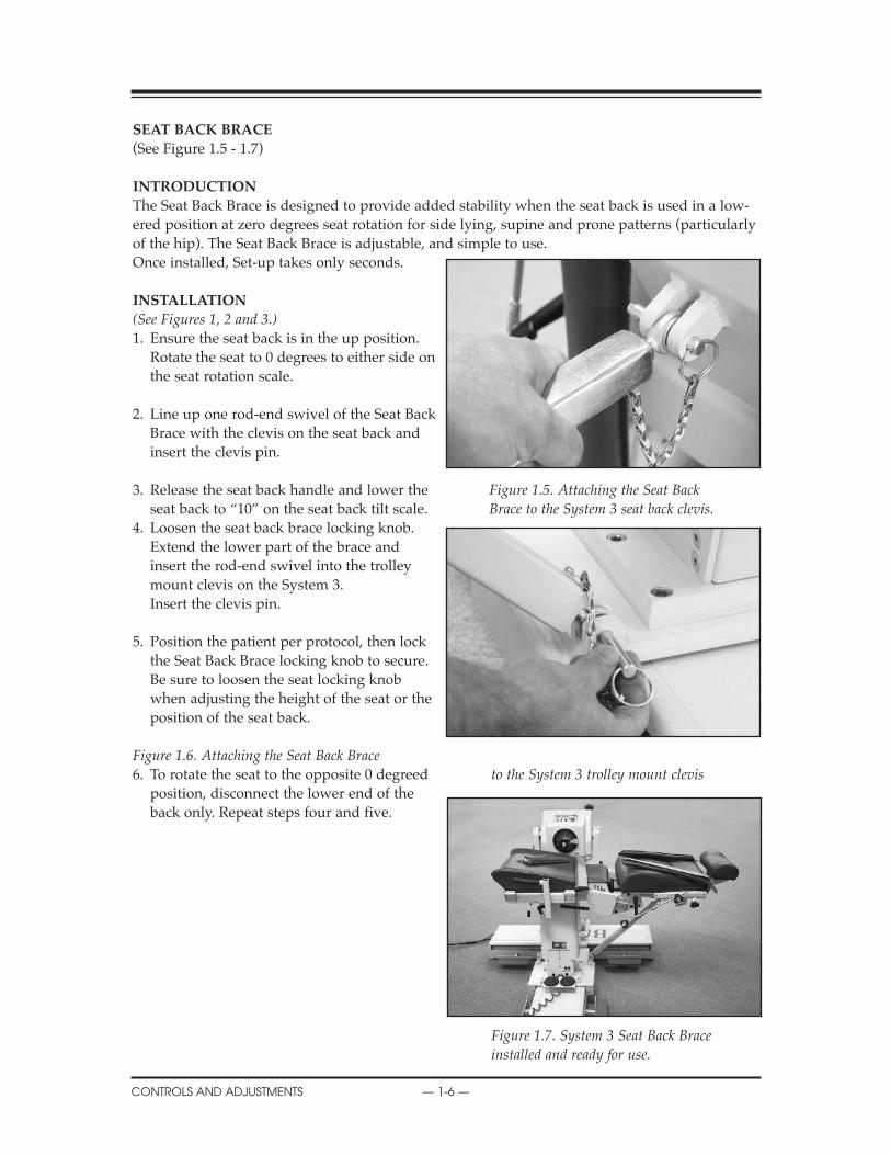
SEAT BACK BRACE
(See Figure 1.5 - 1.7)
INTRODUCTION
The Seat Back Brace is designed to provide added stability when the seat back is used in a low-ered position at zero degrees seat rotation for side lying, supine and prone patterns (particularlyof the hip). The Seat Back Brace is adjustable, and simple to use. Once installed, Set-up takes only seconds.
INSTALLATION
(See Figures 1, 2 and 3.)1. Ensure the seat back is in the up position.
Rotate the seat to 0 degrees to either side onthe seat rotation scale.
2. Line up one rod-end swivel of the Seat BackBrace with the clevis on the seat back andinsert the clevis pin.
3. Release the seat back handle and lower the Figure 1.5. Attaching the Seat Back seat back to “10” on the seat back tilt scale. Brace to the System 3 seat back clevis.
4. Loosen the seat back brace locking knob. Extend the lower part of the brace andinsert the rod-end swivel into the trolleymount clevis on the System 3. Insert the clevis pin.
5. Position the patient per protocol, then lockthe Seat Back Brace locking knob to secure.Be sure to loosen the seat locking knobwhen adjusting the height of the seat or theposition of the seat back.
Figure 1.6. Attaching the Seat Back Brace6. To rotate the seat to the opposite 0 degreed to the System 3 trolley mount clevis
position, disconnect the lower end of the back only. Repeat steps four and five.
Figure 1.7. System 3 Seat Back Brace installed and ready for use.
CONTENTS
CONTROLS AND ADJUSTMENTS — 1-6 —
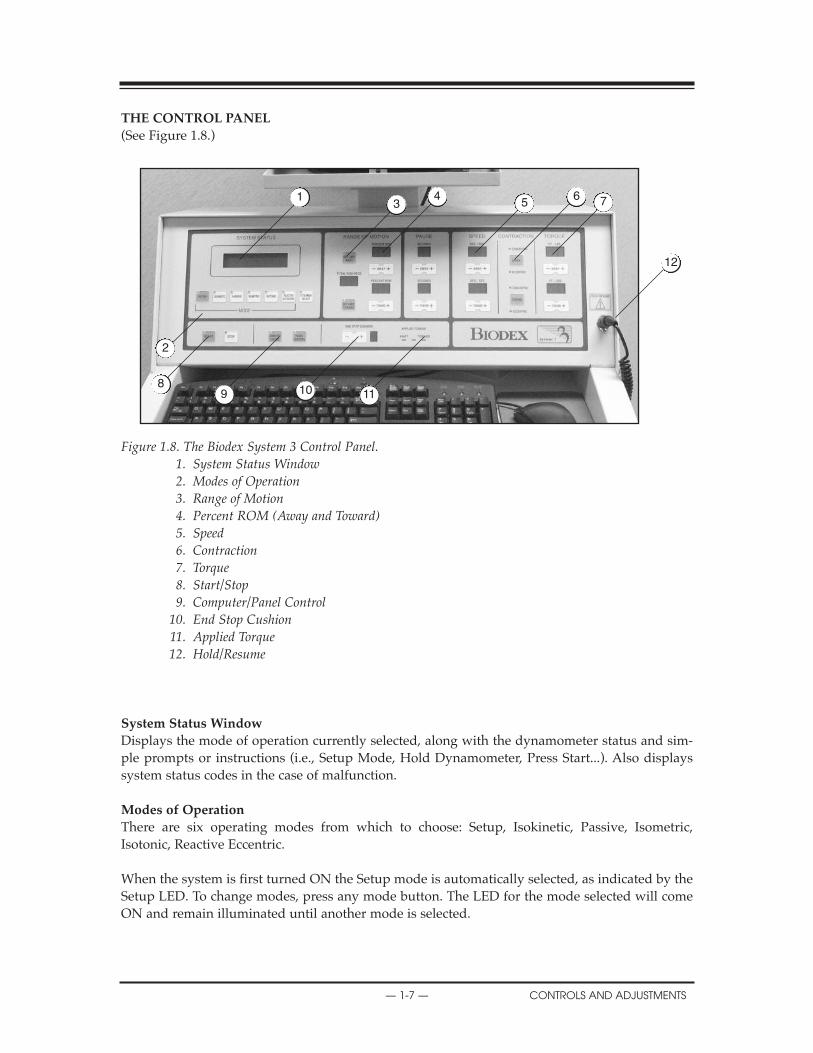
ThE CONTROL PANEL
(See Figure 1.8.)
Figure 1.8. The Biodex System 3 Control Panel. 1. System Status Window2. Modes of Operation3. Range of Motion4. Percent ROM (Away and Toward)5. Speed6. Contraction7. Torque8. Start/Stop9. Computer/Panel Control
10. End Stop Cushion11. Applied Torque12. Hold/Resume
System Status Window
Displays the mode of operation currently selected, along with the dynamometer status and sim-ple prompts or instructions (i.e., Setup Mode, Hold Dynamometer, Press Start...). Also displayssystem status codes in the case of malfunction.
Modes of Operation
There are six operating modes from which to choose: Setup, Isokinetic, Passive, Isometric,Isotonic, Reactive Eccentric.
When the system is first turned ON the Setup mode is automatically selected, as indicated by theSetup LED. To change modes, press any mode button. The LED for the mode selected will comeON and remain illuminated until another mode is selected.
CLINICAL CONSIDERATIONS
— 1-7 — CONTROLS AND ADJUSTMENTS
13
45
6 7
12
111098
2
Attachment Selection
The Attachment Selection button, located immediately to the right of the mode buttons, is used toselect the appropriate sensistivity for the attachment to be used. The system status window willdisplay the currently selected dynamometer attachment (knee is the default attachment). Tochange the selected attachment value, cycle through the available attachments by pressing theAttachment Select button until the desired choice is selected and remains the currently selectedattachment until you change it again.
NOTE: You need not select an attachment every time you use the system. For example, when using the kneeattachment with the knee currently selected, the selection stays valid unless you use the AttachmentSelection button to change it. Attachment selection can also be made with computer control.
Range of Motion
Set Limit Away/Toward: The Set Limit buttons on the control panel allow the clinician to set oradjust patient ROM. These buttons are used in Setup mode, per patient protocol, to set the finalsafe or “target” maximum range of motion for the specific test or exercise to be performed. If a SetLimit LED (Away or Toward) is flashing, there are currently no end ROM limits set for that direc-tion of dynamometer shaft rotation. As a safety precaution, no mode other than Setup can be acti-vated when either Set Limit LED is flashing.
To set patient ROM limits via panel control:1. Select the Setup Mode. Both Set Limit LEDs on the control panel should be flashing.2. Assist or have the patient move through the appropriate range of motion for the initial
direction (away or toward). When the patient has reached max ROM, press the Set Limitbutton to lock in the maximum ROM for that direction. The LED on the control panel forthe direction selected should stop flashing.
3. Move the patient through full ROM in the opposite direction. Press the appropriate SetLimit button once the patient has reached the desired limit. The LED on the control panelfor the second direction should now stop flashing. End limits are now set for both directionsof movement. Total ROM in degrees is displayed in the Total ROM-Degrees window.
To clear patient ROM limits press <Setup>.
NOTE: The ROM settings are not “locked in” until ROM is set for both directions.
CAUTION: Placing your hands or fingers between the dynamometer input shaft (or attachment)
and the mechanical ROM stops may result in serious injury.
ATTENTION: Placer vos mains ou doigts entre le dynamometer données (ou attachement) et le
mécanique ROM arrêts peut résulter dans sérieux blessure.!
!
CONTENTS
CONTROLS AND ADJUSTMENTS — 1-8 —
Clinical Applications
NOTE: Range limits must always be set after the subject is positioned and prior to switching to a
test or exercise mode. Limits should not be set at points that are beyond the safe maximum allow-
able range of motion for the individual subject. The system will not allow selection of mode until
ROM end points are set.
NOTE: Always assume that previously set ROM limits are inappropriate for successive subjects
and for successive joints on the same subject. Always set new limits when testing a new subject or
moving from one joint to the next.
NOTA: Les amplitudes réglées antérieurement doivent être considerée inappropiées a priori.
Régler les limites aprés chaque nouveau positionnement, changement d'accessoire, ou changement
de côte. Au cours de la séance on peut augmenter l'amplitude, mais sans pour autant, passer au-
delà des limites r´glées lors du montage. Avant tout mouvement d'examen ou d'entraînement,
s'assurer que l'amplitude est confortable.
NOTA: Les limites d'amplitude doivent être réglées après le positionnement du patient et avant de
passer à un mode d'entraînement. Ces limites doivent être placées à des angles de sécurité pour le
sujet concerné.
1. As the available range of motion decreases for a particular joint, as in short arc exercise, the speedof movement should decrease also. Limited range of motion will not always provide sufficient timefor the joint to reach higher speeds.
2. Joints that have a greater range of motion, such as shoulders, can generally achieve higher speedsof exercise. Conversely, joints that have less range of motion, such as ankles, cannot attain the higher speeds.
Percent ROM (Away and Toward)
The Percent ROM buttons are used to selectively reduce the total range of motion established during patientsetup. When the Set Limit Away LED is illuminated the Percent ROM -/+ Away button can be used todecrease the percent ROM allowed in the away direction (movement away from the body such as knee exten-sion). Likewise, the Percent ROM -/+ Toward button can be use to decrease the percent ROM allowed in thetoward direction.
NOTE: During exercise, limits can be moved within, but never beyond, the ROM established in the Setup mode. Beforeproceeding with a test or exercise bout, always ensure a comfortable range of motion for the subject.
Pause (0 to 30 seconds)
The Pause buttons, (Away and Toward toggles) allow the introduction of time delays between reciprocatingpatterns of motion during exercise in the Passive mode. The Pause function is inactive when set to zero sec-onds. Use the Pause Away button to increase or decrease the time length of the pause in the away direction(movement away from the body such as knee extension,) as indicated in the Seconds window. Use the PauseToward to increase or decrease the time length of the pause in the toward direction.
!
!
!
!
CONTENTS
— 1-9 — CONTROLS AND ADJUSTMENTS

Clinical Applications
Among other things, the Pause feature may be used to:
1. give commands, especially when patients are working non-reciprocally (concentric/eccentric, eccentric/concentric)2. Provide neurologically impaired individuals with enough time to prepare for a contraction.3. Allow the subject time for a brief passive stretch which can be combined with ultrasound or an ice/friction massage.4. Apply stimulation at terminal points in the ROM.5. Align the subject to perform multi-angle isometrics.
SpeedUse the Speed (Away and Toward) buttons to set the maximum velocity for each direction of movement inthe Isokinetic, Passive or Reactive Eccentric mode. The velocities selected are shown in degrees-per-second inthe Degs/Sec. window for each direction, (Concentric max speed: 500-deg./sec., eccentric max speed: 300degrees per second.)
ContractionThe Contraction buttons are active for isokinetic and isotonic modes only. In both modes, the contraction set-ting defaults to concentric/concentric movement. Use the Away or Toward button to change the contractiontype for the desired direction (i.e., concentric/concentric, concentric/eccentric or eccentric/concentric).Contraction type is indicated by the LEDs for each direction of movement. The direction the attachment ismoving will determine the contraction (for quadriceps, choose concentric away and eccentric towards.)
TorqueThe Torque buttons, Away and Toward, provide a means of keeping a subject’s torque level either at or belowan operator-specified level of torque production while performing eccentric contractions in the Passive orReactive Eccentric and Isokinetic mode. In Passive Mode, when a subject exerts an eccentric torque in excessof the torque limit selected, the dynamometer shaft stops rotating until the force output is reduced to a valuebelow the set limit. The subject must therefore work below the limit threshold to continue through the ROM.The Torque buttons are also used to select the desired torque control value in Isotonic mode. In Eccentricmode, the torque value represents the minimum force required to initiate motion (10% of torque limit), andthe maximum force the patient can produce prior to stopping the attachment. The patient must work betweenthe 10% minimum and torque limit to keep the attachment moving.
The numerical values displayed in the Torque Windows represent foot-pounds of torqued (Newton Metersfor International Systems.)
Under panel control, torque can be adjusted at anytime during the exercise or test session to accomodate thepatient’s gains.
Start/StopPress the Start button to allow dynamometer shaft rotation. Press the Stop button to stopdynamometer shaft rotation (cut off power).
Computer/Panel ControlOn power-up, the Biodex System automatically defaults to Panel Control operation as indicatedby the Panel Control LED. To access computer control for automated protocols, press theComputer Control button. The Computer Control LED will illuminate, indicating that automatedprotocols may now be selected.
End Stop CushionThe End Stop Cushion button provides a means of varying the point at which the decelerationstarts (1=hard, 9=soft). Deceleration occurs earlier in the ROM with a softer cushion.
CONTROLS AND ADJUSTMENTS — 1-10 —
CLINICAL CONSIDERATIONS
Clinical Applications
As a general rule, “hard” cushions (short range of deceleration) are used for testing while “soft” cushionsare selected for rehabilitation applications. This is especially true in a small range of motion or at high iso-kinetic speeds. The higher the cushion the shorter the amount of time spent at isokinetic speed.
Applied Torque
Illumination of any of the three Applied Torque LED’s indicates the dynamometer’s torque sens-ing assembly is generating a signal. The center LED indicates the sensor is active but is not sens-ing any torque. The left LED indicates torque is being applied in the away direction while the rightLED indicates torque is being applied in the toward direction.
Clinical Applications
Many clinicians use the Applied Torque indicators for biofeedback during the rehabilitation process.
— 1-11 — CONTROLS AND ADJUSTMENTS
COMPUTER PRELIMINARIES

ThE CONTROLLER (Located at bottom of Computer Data Station)
Main Power Switch (Rear of Unit)
Controls main power supply to controller, computer and dynamometer. Contains a circuit break-er to protect against extreme power surges. Breaker is reset by turning the Power Switch OFF (0)and then ON (l).
NOTE: It is not necessary to turn the system OFF each day. Use the Dynamometer and Computer PowerSwitches described below for daily shut-down. Use the Main Power Switch only if you intend toshut the system down for an extended period of time.
Dynamometer Power Switch
This switch controls power to the dynamometer. In the ON position, power to the dynamometeris enabled. In the OFF position, the dynamometer is on Standby.
Computer Power Switch
Controls power to the computer and peripherals (including printer and monitor). In the ON posi-tion, power to computer, monitor and printer are ON. In the OFF position, power to the comput-er, monitor and printer are OFF.
NOTE: Be sure to properly exit and close down the Biodex Advantage Software application and WindowsPrograms before turning off the computer.
Status/Diagnostics Panel (LEDs)
Located to the left of the Dynamometer and Computer Power Switch, this panel provides infor-mation to assist in troubleshooting of dynamometer/control panel problems. In the event of a sys-tem malfunction, always be sure to record which LEDs light before attempting to correct a prob-lem or restart the system. Contact a Biodex Service Representative whenever the status panel indi-cates a malfunction.
Figure 1.9. The Biodex System Controller front panel (left) and rear of unit (right).1. Main Power Switch2. Dynamometer Power Switch3. Controller Power Switch4. Status/Diagnostics Panel (LED’s)
X
CONTROLS AND ADJUSTMENTS — 1-12 —
1
4
32

DYNAMOMETER ATTAChMENTS
Figure 1.10.Shoulder Attachment(Insert in Shoulder/Elbow Adapter)
Patterns:Shoulder: Ex/Flex
Ab/AdDiagonals
Figure 1.11.Shoulder/Elbow Attachment(Insert in Shoulder/Elbow Adapter)
Patterns:Shoulder: In/Ex RotationElbow: Ex/Flex (remove cuff)
NOTE: Only one Shoulder/Elbow Adapter is supplied. The same adapter is used with the Shoulder Attachment and Shoulder/Elbow Attachment.
Figure 1.12.Knee Attachments (Left and Right)
Patterns:Knee: Tibial In/Ex RotationAnkle: Plantar/Dorsiflexion
Inversion/Eversion
NOTE: Ensure finger guard is in placewhen using this attachment. See Figure 1.16.
NOTA: S’assurer que le doigtier est bien en place lorsqu’on utilise cet accessoire. voir figure 1.16.
Figure 1.13.Wrist Attachment
Patterns:Wrist: Ex/Flex
Radial/Ulnar DeviationForearm: Pro/Supination
!
— 1-13 — CONTROLS AND ADJUSTMENTS
APPLICATIONS
Shoulder/Elbow Adapter
Shoulder Attachment
Shoulder/Elbow Adapter
Shoulder/Elbow Attachment
KneeAttachment
WristAttachment
Knee Adapter
Wrist Adapter
!
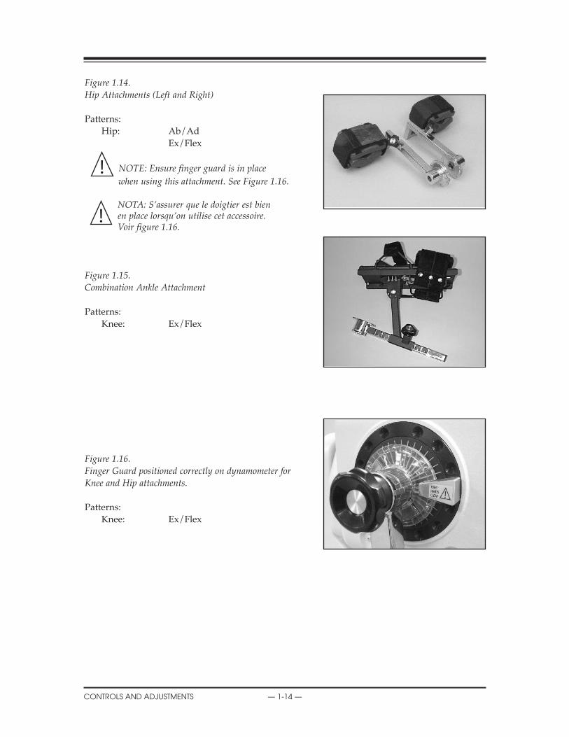
Figure 1.14.Hip Attachments (Left and Right)
Patterns:Hip: Ab/Ad
Ex/Flex
NOTE: Ensure finger guard is in place
when using this attachment. See Figure 1.16.
NOTA: S’assurer que le doigtier est bien en place lorsqu’on utilise cet accessoire. voir figure 1.16.
Figure 1.15.Combination Ankle Attachment
Patterns:Knee: Ex/Flex
Figure 1.16.Finger guard positioned correctly on dynamometer forKnee and Hip attachments.
Patterns:Knee: Ex/Flex
!
APPLICATIONS
CONTROLS AND ADJUSTMENTS — 1-14 —
!
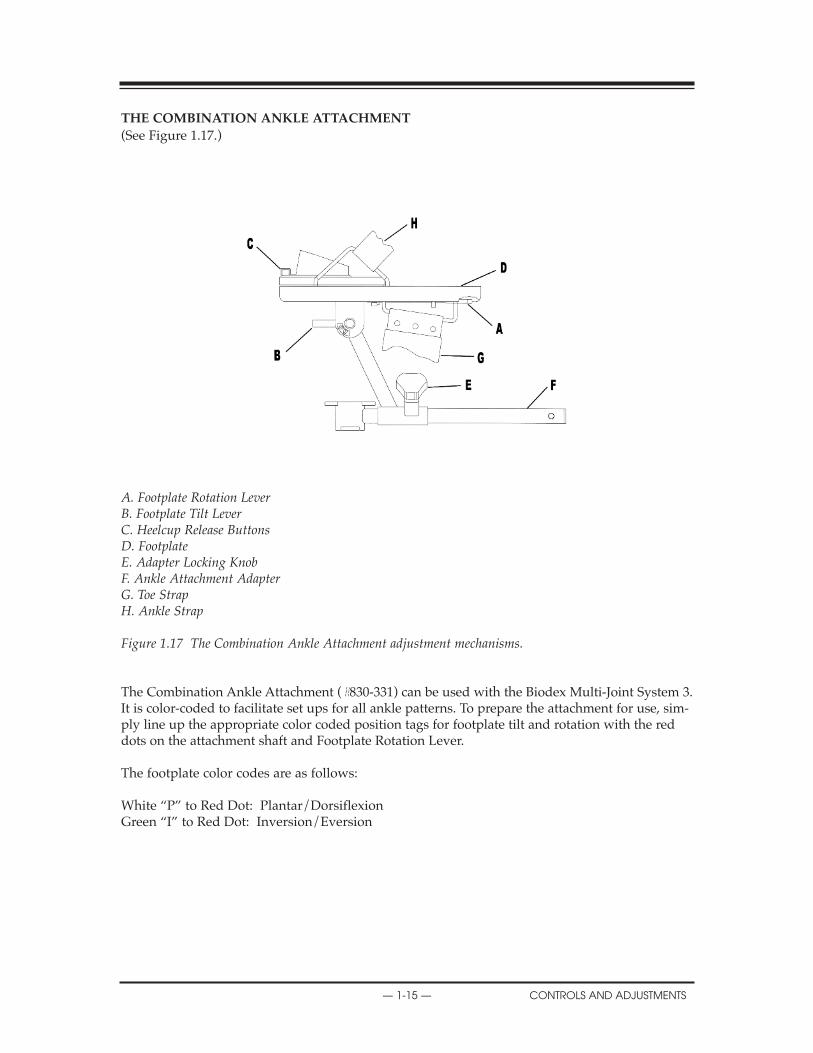
ThE COMBINATION ANKLE ATTAChMENT
(See Figure 1.17.)
A. Footplate Rotation LeverB. Footplate Tilt LeverC. Heelcup Release ButtonsD. FootplateE. Adapter Locking KnobF. Ankle Attachment Adapterg. Toe StrapH. Ankle Strap
Figure 1.17 The Combination Ankle Attachment adjustment mechanisms.
The Combination Ankle Attachment (#830-331) can be used with the Biodex Multi-Joint System 3.It is color-coded to facilitate set ups for all ankle patterns. To prepare the attachment for use, sim-ply line up the appropriate color coded position tags for footplate tilt and rotation with the reddots on the attachment shaft and Footplate Rotation Lever.
The footplate color codes are as follows:
White “P” to Red Dot: Plantar/DorsiflexionGreen “I” to Red Dot: Inversion/Eversion
— 1-15 — CONTROLS AND ADJUSTMENTS
COMPUTER PRELIMINARIES

ADJUSTING ThE FOOTPLATE (Refer to Figure 1.17)
Footplate RotationThe Footplate Rotation Lever is located on the underside of the footplate at the toe end. Pull thelever and hold it back while you rotate the footplate until the desired color-coded position tagaligns with the lever. Release the lever and ensure that the appropriate footplate peg is securedin the lever’s notch.
Footplate Tilt The Footplate Tilt Lever is located on the underside of the footplate just above the color-codedposition tags. Loosen the lever and tilt the footplate to align the color-coded tags per test orexercise protocol by aligning the white “P” with the red dot for plantar\dorsiflexion or thegreen “I” to the red dot for Inversion\Eversion. Tighten the lever to secure the footplate inplace.
heel Cup PositionTo facilitate alignment of the subject’s axis of rotation with the dynamometer shaft, it may benecessary to raise or lower the patient’s foot on the footplate by adjusting the heel cup position.The Heel Cup Release Buttons are located on the top side of the footplate at the heel end.Squeeze the Heel Cup Release Buttons together and slide the support cup to the desired posi-tion. Release the buttons to lock the heel cup in place.
Two Heel Cups are provided. One is designed with a high, narrow, rubber support for use withpatients where it is desirable to perform the exercise without shoes. The other heel cup isdesigned with a low, wide, plastic support for patients wearing shoes. The Heel Cups are inter-changeable.
To remove or insert either Heel Cup, depress the Heel Cup Release Buttons and slide the cupinto or out of the footplate attachment from the toe end. The Heel Cup can then be positioned asexplained above.
Toe and Ankle StrapsOnce all adjustments to the footplate have been completed, secure the patient’s foot using boththe foot and ankle straps.
COMPUTER PRELIMINARIES
CONTROLS AND ADJUSTMENTS — 1-16 —
CONSIDERATIONS FOR SAFE OPERATION OF YOUR BIODEX SYSTEM
1. The clinician should always be present during testing or exercise sessions. Do not allow sub-jects to test or exercise by themselves.
2. Range limits should always be set after the subject is positioned according to protocol andbefore switching to a test or exercise mode. Limits should never be set at points that arebeyond the safe maximum allowable range of motion for the individual subject.
Always assume that previously set limits are inappropriate for successive subjects, or for suc-cessive joints on the same subject. Limits should be canceled by pressing Set-up, Start and Set-up again at the completion of each test or exercise session. Always press the Setup button on thecontrol panel prior to setup of a new subject or before subsequent setups on the same subject.
Remember, Setup mode is used for patient setups and adjustments, not for exercise or testing.
3. Range of motion limits should be set so that the mechanical stop on the attachment or fixturewill not contact the mechanical stop on the dynamometer. Metal-to-metal contact of theseparts during operation will override the system’s normal deceleration function (cushion),causing harsh impacts at ends of ROM.
4. Always educate subject as to function and use of the Comfort Stop buttons. Always place thehand-held remote Comfort Stop (on black coiled cord) in the subject’s free hand before thestart of any test, exercise or biofeedback session.
5. During setup, check subject positioning and ability to complete range of motion (slowly) priorto securing stabilization straps. Ensure that both the positioning chair and dynamometer aresecurely locked in detentes before allowing subject to move through ROM.
6. Before pressing the Start button, always inform the subject that the input arm will now be ableto move.
7. Always keep the surrounding area free of equipment and other personnel, especially whenthe passive mode is to be used. Check for clear, unobstructed path of movement pattern(through complete ROM).
8. Do not operate equipment that has malfunctioned until it has been serviced by a qualifiedtechnician or use has been approved by a Biodex Service Representative.
9. Use equipment only with recommended power supplies, grounding, and surge suppression.(Refer to Biodex site survey or contact Biodex Service Department for specifications).
CAUTION: Placing your hands or fingers between the dynamometer input shaft (or attach-
ment) and the mechanical ROM stops may result in serious injury.
ATTENTION: Placer vos mains ou doigts entre le dynamometer données (ou attachement) et le
mécanique ROM arrêts peut résulter dans sérieux blessure.!
!
!
— 2-1 — OPERATION
2. OPERATION
FONCTIONNEMENTPoints à retenir pour un fonctionnement sécuritaire de votre système Biodex
1. Le clinicien doit toujours être présent durant les séances de test ou d’exercice. Ne pas per-mettre aux sujets de se tester ou de s’exercer seuls.
2. Les limites d’amplitude doivent toujours être fixées après avoir positionné le sujet suivant leprotocole et avant de passer à un mode de test ou d’exercice. On ne doit jamais régler leslimites à des points qui dépassent l’amplitude du mouvement maximale permissible pour lasécurité du sujet dont il s’agit.
Toujours partir du principe que les limites fixées précédemment sont inappropriées pour lessujets qui suivront ou pour une succession d’articulations chez le même sujet. Il faut annulerles limites en appuyant sur Réglage, Départ, puis Réglage à nouveau, à la fin de chaqueséance de test ou d’exercice. Toujours appuyer sur la touche Réglage sur le tableau de com-mande avant le réglage pour un nouveau sujet ou avant tout réglage subséquent sur lemême sujet.
À noter que le mode Réglage sert au réglage et aux rajustements pour le patient, et non auxexercices ou aux tests.
3. On doit fixer les limites de l’amplitude du mouvement de telle sorte que l’arrêt mécaniquede l’accessoire ou de la fixation n’entre pas en contact avec l’arrêt mécanique dudynamomètre. Tout contact métal sur métal de ces pièces en cours de fonctionnement désac-tive la fonction normale de décélération (coussin), entraînant des impacts durs en fin decourse.
4. Toujours veiller à bien informer le sujet de la fonction et de l’utilisation des touches Arrêtconfort. Toujours placer la télécommande Arrêt confort (avec cordon extensible noir) dans lamain libre du sujet avant le départ de toute séance de test, d’exercice, ou de biofeedback.
5. Durant le réglage, vérifier le positionnement du patient et sa capacité de se mouvoir (lente-ment) dans toute l’amplitude du mouvement, avant de fixer les sangles de stabilisation.S’assurer que le siège de positionnement et le dynamomètre sont tous deux bien verrouillésdans leurs crans d’arrêt avant de permettre au sujet d’évoluer dans l’amplitude du mouve-ment.
6. Avant d’appuyer sur la touche Départ, toujours informer le sujet que le bras de saisie peutmaintenant se déplacer.
7. Garder en tout temps la zone environnante libre de tout équipement et d’autres personnes,surtout lorsqu’on utilise le mode passif. S’assurer d’une trajectoire libre de tout obstaclepour les évolutions dans toute l’amplitude du mouvement.
8. Ne pas faire fonctionner un équipement qui a subi une panne avant qu’il n’ait fait l’objetd’un entretien par un technicien qualifié, ou que son utilisation n’ait été autorisée par unagent du service après-vente de Biodex.
9. N’utiliser l’équipement qu’avec les alimentations électriques, la mise à la terre et la protec-tion contre les surtensions préconisées. (Se reporter au sondage sur les installations deBiodex ou communiquer avec le service après-vente de Biodex pour le cahier des charges.)
XXX
OPERATION — 2-2 —
!
GENERAL OPERATING INSTRUCTIONS (MEChANICAL)
Readying the System for Use
1. Turn the main power switch on the back of the controller to the ON (1) position. The message“Power-UP” will temporarily appear in the in the system status window on the control panel.
2. Ensure that the dynamometer and computer power switches on the front of the controller areset to the ON (l) position.
3. Once the system is fully powered, the message “REMOVE ATTACHMENT, PRESS START”will appear in the system status window. Remove the attachment from the dynamometer ifyou have not already done so. Press the Start key on the control panel.
4. The dynamometer shaft will now begin to rotate and the system will display a message thatit is initializing the dynamometer. Once the automatic initialization/calibration procedure iscompleted, press Start as prompted by the system status window. During dynamometer inti-tialization the system diagnositics and calibration are being performed so it is very importantnot to interfere with the rotating shaft.
5. The system is now ready for use. The Setup mode is automatically selected and the Set Limitbutton LEDs should be flashing.
Shutting Down the System at the End of the Day
At the end of your day, switch the computer and dynamometer power switches, located on thefront of the controller, to the OFF position. If the Biodex System will not be used for an extendedperiod of time, you may also want to switch the controller OFF via the Main Power switch on itsrear panel.
NOTE: If using the computer, you must exit both the Biodex Advantage Software and the Windows pro-gram prior to shutting down the system. Failure to do so may result in lost or damaged files. To quitWindows and shut down your computer:
1. Close the Biodex Advantage Software application by clicking on the “X” in the top right corner ofthe screen.
2. Click the <Start> button at the lower left side of the screen to access the Start menu.3. Click the “Shut Down” to bring up the Shut Down window.4. Click “Yes” to shut down the computer. A screen message will be displayed when it is safe to turn
the computer OFF.
Following is a general guideline for use of the Biodex in each of its operating modes. These guide-lines are of a mechanical nature and do not reflect use of the computer software. They are pre-sented only as an example to help familiarize you with the mechanical aspects of equipment setupand each of the various modes of operation.
TESTING A PATIENT
— 2-3 — OPERATION
ThE SETUP MODE
The Setup mode is used during the system’s preparation, prior to actual exercise or testing. In thismode the dynamometer shaft is free to rotate (at 45 degrees per second) so that fixtures can besecured, range of motion limits can be set, and the subject can be properly positioned and stabi-lized prior to exercise. The following general procedure is provided to help clarify use of the Setupmode.
NOTE: Subject positioning and stabilization are always performed in the Setup mode.
Setup Mode (General Instructions)
1. Turn the system ON. The System Status Window should indicate that the Setup mode hasbeen automatically selected. Power to all components should be ON. Press “Panel Control”on the Control Panel.
2. Attach appropriate fixture to dynamometer shaft, aligning the red dot on the dynamometershaft to stamped dot on the attachment (improper alignment will reduce available range ofmoton). Secure with locking knob. Position dynamometer and chair per test or exercise pro-tocol.
3. Press the Start button.
4. Press the Attachment Select button on the control panel. The system status window will dis-play the currently selected dynamometer attachment (knee is the default attachment). Tochange the selected attachment value, cycle through the available attachments by pressing theAttachment Select button until the desired choice is displayed. After a 5-second pause (orwhen any mode button is selected,) the system exits the attachment selection procedure. Theattachment last displayed is automatically selected and remains the currently selected attach-ment until you change it again.
NOTE: When using panel control, you must select the appropriate attachment setting (in computercontrol the attachment setting is automatically selected when you select the joint and exercisepattern in protocol).
5. Position and stabilize subject correctly for the intended protocol by adjusting the seat height,seat position and seatback tilt. Dynamometer height, angle, rotation, and position may alsoneed adjustment. Secure appropriate stabilization straps. Be sure to correctly align suggestedanatomical axis with the dynamometer shaft.
6. Explain use of hand-held and dynamometer comfort stops to subject.
XX
OPERATION — 2-4 —

7. Set patient ROM.• Assist or have the patient move through the appropriate range of motion for the initial direc-
tion (away or toward). When the patient has reached max ROM, press the Set Limit buttonto lock in the maximum ROM for that direction. The LED on the control panel for the direc-tion selected should stop flashing for that direction.
• Move the patient through full ROM in the opposite direction. Press the appropriate Set Limit button once the patient has reached the desired limit. The LED on the control panelfor the second direction should now stop flashing. End limits are now set for both directions of movement. Total ROM in degrees is displayed in the Total ROM-Degrees window.
NOTE: When in Isometric mode, the dynamometer shaft may be moved by pressing (and holding) theTowards/Away button corresponding to the direction the shaft must turn. Releasing the but-ton locks the shaft at the new position. This function of the Towards/Away buttons has no effecton the range of motion limits previously established in Setup Mode.
8. Select the desired test or exercise mode from the control panel. (See the following section forspecific infomation on each mode of operation.)
XX
— 2-5 — OPERATION
ISOKINETIC MODE
In this mode, the dynamometer acts to control velocity, allowing the subject to accelerate up to,but no higher than, the maximum speed value selected for each direction of shaft rotation (accom-modating resistance). The subject may freely decelerate or change direction of movement at anypoint within the range of motion.
The following general procedure is provided to help clarify use of Isokinetic mode.
Isokinetic Mode (General Instructions)
1. After completing the Setup mode routine, select Isokinetic mode from the control panel.
2. Set Percent ROM (if desired). The Percent ROM buttons are used to selectively reduce the totalrange of motion established during patient setup. Use the Percent ROM Away and Towardbuttons to decrease the percent ROM allowed in either direction.
3. Set contraction type, concentric/concentric, concentric/eccentric or eccentric/concentric. ForIsokinetic mode, the system automatically defaults to concentric/concentric movement asindicated by the contraction button LEDs. To alter this selection, use the Contraction Away orToward button to select the appropriate contraction type for each direction of movement. Thecontraction type selected for each direction of movement is indicated by the contraction but-ton LED. When using eccentric contractions, the patient will have to apply 10% of the settorque value to initiate motion, and exceed the torque limit value to stop. The direction theattachment is moving will determine the contraction. (For example, quadriceps only, chooseconcentric away and eccentric towards).
NOTE: For eccentric contractions in all Isokinetics modes, the torque limit may be set as high as 310 ft-lb This will allow the subject to exert as much as 300 ft-lb of torque without stoppingthe dynamometer input shaft.
4. Set speed. Use the Speed Away/Toward buttons on the control panel to set the maximumvelocity for each direction of movement.
NOTE: For eccentric/eccentric contractions, select Reactive Eccentric Mode.
5. Set End Stop Cushion. Use the End Stop Cushion button to set the point in each direction ofthe subject’s ROM at which deceleration will begin. The cushion level selected is displayed inthe window immediately to the right of the button. As a general rule, “hard cushions” (lownumbers) are used for testing applications while “soft” cushions (high numbers) are selectedfor rehabilitation applications.
6. Inform patient that the test or exercise session is ready to begin and that the dynamometer will nowallow for rotation of the dynamometer shaft. Press Start to begin the test or exercise session. Thepatient will not experience resistance until meeting or exceeding the pre-selected speed. The resis-tance met will equal the patient’s effort output. If the subject movement stops, resistance stops. Asthe subject produces less force or more force the equivalent opposing resistance is experienced.
NOTE: Always be sure the control panel settings are correct before engaging this device with the Startbutton. Set range of motion limits after placing subject into restraints. Have subject movethrough ROM prior to starting test or exercise. Always reset range of motion limits or pressSetup when proceeding from one joint, subject, or attachment to another.
NOTA: vérifier que réglages du contrôler sont appropiés avant de démarrer tout mouvement. Réglerles limites de mouvement aprés le positionnement du patient. Faire faire le mouvement par lepatient avant de démarrer tout examen ou entraînement avecl'appareil.
XX
OPERATION — 2-6 —

Isokinetic Mode Clinical Applications
1. The Isokinetic mode may be used at higher speeds in order to simulate functional or sportsactivities. It can also be used early on in the rehabilitation process to prevent compression andtranslation in the knee joint.
2. The Isokinetic mode may be used with differing bi-directional velocities to simulate function-al activities or place the focus of the activity on one specific muscle group.
3. There is a 15-degree physiologic overflow in strength on each side of the end ROM (30º totalcarry-over) with a limited range of motion strengthening program performed isokinetically(Halbach, 1985).
4. Choose con/ecc or ecc/con to isolate one muscle group.
5. Exercising at a specific speed has shown strength gains which overflow to both faster andslower speeds. However, there is enough research to demonstrate that by exercising at every30 degrees/second, physiological overflow will occur with regards to specific strengtheningat each speed exercised (Davies, G.J., 1987.)
6. In the Isokinetic mode, the Force-Velocity relationship of muscle dictates that as speed of con-traction increases concentrically, the muscular tension (and therefore torque) decreases.(Davies, G.J., 1987.)
7. A velocity spectrum is recommended which will start the subject at either a high or low speed,depending on the pathology and status of the subject, and progress to other speeds. Varyingthe number of repetitions (i.e., less reps at slow speeds, more reps at high speeds), will helpkeep the work performed consistent over the range of the velocity spectrum.
8. Exercising at higher speeds has shown excellent benefits for endurance gains. This will limitcompression on joints, tension developed in the muscles and tendons, and generally allowsthe subject to do larger numbers of sets or repetitions, which transfers to daily activities.
9. Keep in mind the stretch shortening cycle. It has been found that an eccentric contraction per-formed before a concentric contraction results in a more forceful concentric contraction than aconcentric contraction performed alone (Duncan, P., et. al., 1989). High speed contractions fol-lowed by slow speed contractions will simulate an isolated plyometric activity.
XX
— 2-7 — OPERATION
ThE PASSIVE MODE
The Biodex Passive mode allows the dynamometer to provide continuous motion at constantvelocity, with direction changes occurring only when range of motion limits are reached.
In Passive mode, the dynamometer initiates motion when the Start button is pressed, requiring noactive participation by the subject.
The following general procedure is provided to help clarify use of the Passive mode.
Passive Mode (General Instructions)
1. After completing the Setup mode routine, select Passive mode from the control panel.
2. Set Percent ROM. The Percent ROM buttons are used to selectively reduce the total range ofmotion established during patient setup. Use the Percent ROM Away and Toward buttons todecrease the percent ROM allowed in the either direction.
3. Set Pause. The Pause buttons (Away and Toward toggles) on the Control Panel allow the intro-duction of time delays between reciprocating patterns of motion during exercise. Use thesebuttons to program in the pause desired for each direction of movement.
4. Set speed. Use the Speed Away/Toward buttons on the control panel to set the maximumvelocity for each direction of movement (Once the test or exercise begins, the system willramp up to the selected speed.)
5. Set Torque Limits. The Torque buttons, Away and Toward, provide a means of keeping a sub-ject’s torque level either at or below an operator-specified level of torque production while per-forming eccentric contractions in the Passive, Reactive Eccentric and Isokinetic mode. In thePassive Mode, when a subject exerts an eccentric torque in excess of the torque limit selected,the dynamometer shaft stops rotating until the torque output is reduced to a value at or belowthe set limit. The subject must therefore work at or below the limit threshold to continue throughthe ROM. The numerical values displayed in the Torque Windows represent foot-pounds oftorque. In short, this setting allows the clinician to control the maximum amount of torquehe/she wants the subject to develop eccentrically. The direction the dynamometer shaft is mov-ing during the eccentric contraction is the torque limit you will need to set. To limit eccentricquadriceps, set the toward limit. To limit shoulder external rotators, set the toward limit.
6. Set End Stop Cushion. Use the End Stop Cushion button to set the point in each direction ofthe subject’s ROM at which deceleration will begin. The cushion level selected is displayed inthe window immediately to the right of the button. As a general rule, “hard cushions” (lownumbers) are used for testing applications while “soft” cushions (high numbers) are selectedfor rehabilitation applications.
7. Inform patient that the test or exercise session is ready to begin and that the dynamometer willnow provide passive motion to the attachment. Press Start to begin the test or exercise session.The system will ramp up to the selected speed.
NOTE: For Passive mode dynamometer speeds of 75 degrees/sec. and higher, you must press the
Start button twice for high-speed enable.
NOTE: Always be sure the Control Panel settings are correct before engaging this device with the
Start button. Set range of motion limits after placing subject into restraints. Have subject
move through ROM prior to starting test or exercise. Always reset range of motion limits
or press Setup when proceeding from one joint, subject, or attachment to another.
NOTA: vérifier que réglages du contrôler sont appropiés avant de démarrer tout mouvement.
Régler les limites de mouvement aprés le positionnement du patient. Faire faire le mou-
vement par le patient avant de démarrer tout examen ou entraînement avecl'appareil.
!
!
OPERATION — 2-8 —
TESTING A PATIENT
Passive Mode Clinical Applications
1. The Passive mode is frequently used post-operatively for the benefits of continuous passivemotion, which assist with nourishment of the joint.
2. The Passive mode may be used isokinetically in the agonistic direction and then passively inthe antagonistic direction or vice versa.
3. The Passive mode may be used to exercise or test isokinetically. Subjects that cannot meet thespeed, will be passively moved through this portion of the range.
4. The Passive mode may be used for passive stretching. When this is performed, the torque lim-its in each direction should be set low. If the subject feels uncomfortable, they may resist themotion and the unit will stop, e.g., if the clinician is trying to increase knee flexion the subjectwill be passively flexed. If at any time the subject is uncomfortable, they may resist the flex-ion movement and isometrically exceed the Toward torque limit. This will stop the unit. ThePause buttons can also be used to hold the patient at the end ROM corresponding to the direc-tion the pause is set.
5. For knee, shoulder flex/ex, ab/ad, and lumbar movements, ensure torque limits are set toovercome limb weight.
6. Passive motion may be used to warm-up and cool-down a subject, stretching ROM, and toperform contract/relax protocols . Used during rest periods, passive motion can help preventmuscles from “tightening up” before the next set of repetitions.
7. By instructing the subject to move the limb at a speed that will keep the Away and TowardApplied Torque Indicator ON and the middle Applied Torque Indicator OFF, the Passivemode can be used to provide biofeedback and stimulate joint and muscle mechanoreceptorsto improve proprioception.
8. In the case of poor muscle strength, passive mode allows for active assistive motion whichwill initiate or continue motion of the subject.
9. Contract/Relax may be performed in the Passive mode. Range of motion limits are selectedto include the entire range the subject should be able to achieve that day. It is recommendedthat the Limit Set buttons are set no more then five degrees outside of the beginning range.Percent Range dials are then decreased to an appropriate level so that the entire range is com-fortable. The subject is placed on the unit with the comfort stop in hand. As the subject is pas-sively moved in one direction, they exert force in the opposite direction. The torque limit inthe opposing direction must be set low enough so that the subject exceeds the limit and per-forms an isometric contraction. At this time, the clinician slightly increases the range ofmotion using the Percent Range dial in the appropriate direction. The procedure is repeatedfor as many cycles as desired.
10. Immediately post exercise, some subjects exhibit joint effusion. Application of ice while mov-ing passively at 20 degrees per second has been reported to reduce post exercise swelling anddiscomfort. This may also be done in conjunction with electric stimulation to further assistedema control.
X
— 2-9 — OPERATION

ISOMETRIC MODE
In this mode, the dynamometer maintains zero velocity at any selected point in the range ofmotion. Significant change in joint angle and overall muscle length does not occur.
Isometric Mode (General Instructions)
1. After completing the Setup mode routine, select Isometric mode from the control panel.
2. Press and hold down the Towards/Away Button for the desired direction to free up thedynamometer shaft. While holding down the Towards/Away Button, instruct/assist the sub-ject to move the limb to the desired point in the ROM. Release the Rotate Button to select theROM position.
3. Inform patient that the test or exercise session is ready to begin. Press Start to begin the test orexercise session.
4. Range of Motion changes are made by holding down the Towards/Away Button and movingthe limb in the corresponding direction. Once the desired point in the range of motion is met,the button is released and the attachment locks into position.
NOTE: Always be sure the control panel settings are correct before engaging this device with the
Start button. Set range of motion limits after placing subject into restraints. Have subject
move through ROM prior to starting test or exercise. Always reset range of motion lim-
its or press Setup when proceeding from one joint, subject, or attachment to another.
NOTA: vérifier que réglages du contrôler sont appropiés avant de démarrer tout mouvement.
Régler les limites de mouvement aprés le positionnement du patient. Faire faire le mou-
vement par le patient avant de démarrer tout examen ou entraînement avecl'appareil.
Isometric Mode Clinical Applications
1. The Isometric mode may be used pre- or post-surgery with discretion.
2. The Isometric mode may be used near a painful range for strength carryover into the painfulrange. Overflow has been found to be plus or minus as much as 10 degrees.
3. Isometric holds can be checked for quality of contraction. Monitoring these can help set goalsand monitor progress.
4. The Isometric mode can be used very effectively to initiate contractions submaximally. Makesure to stabilize other body parts to prevent compensation. Relaxation can be assisted by theapplication of heat, cold, or biofeedback.
!
!
THE STABILITY REPORTS
OPERATION — 2-10 —
ISOTONIC MODE
Isotonic Mode (General Instructions)
In this mode, the dynamometer requires the patient to meet a minimum selected torque limit inorder to move the input arm. Thus, speed is variable but torque is constant.
1. After completing the Setup mode routine, select Isotonic mode from the control panel.
2. Set Percent ROM. The Percent ROM buttons are used to selectively reduce the total range ofmotion established during patient setup. Use the Percent ROM Away and Toward buttons todecrease the percent ROM allowed in the either direction.
NOTE: When working with eccentric contractions, do not set the range of motion at the extreme end pointsas the patient may not be able to intiate movement due to length-tension curves of the muscles.
3. Set contraction type, concentric/concentric, concentric/eccentric or eccentric/concentric. ForIsotonic mode, the system automatically defaults to concentric/concentric movement as indi-cated by the contraction button LEDs. To alter this section, use the Contraction Away orToward button to select the appropriate contraction type for each direction of movement. Thecontraction type selected for each direction of movement is indicated by the contraction but-ton LED. The speed of the eccentric contraction can be controlled (faster eccentric speeds pro-duce greater torque than slower eccentric speeds.)
4. Set Torque Limits Toward and Away. In Isotonic Mode, the Torque buttons are used to speci-fy a minimum torque threshold. During the exercise or test session, when this threshold is sur-passed by the subject, isotonic motion can occur.
5. Set End Stop Cushion. Use the End Stop Cushion button to set the point in each direction ofthe subject’s ROM at which deceleration will begin. The cushion level selected is displayed inthe window immediately to the right of the button. As a general rule, “hard cushions” (highnumbers) are used for testing applications while “soft” cushions (low numbers) are selectedfor rehabilitation applications.
6. Inform patient that the test or exercise session is ready to begin and that the dynamometer willallow for rotation once the preset torque threshold is obtained. Press Start to begin the test orexercise session.
NOTE: Always be sure the control panel settings are correct before engaging this device with the
Start button. Set range of motion limits after placing subject into restraints. Have subject
move through ROM prior to starting test or exercise. Always reset range of motion limits
or press Setup when proceeding from one joint, subject, or attachment to another.
NOTA: vérifier que réglages du contrôler sont appropiés avant de démarrer tout mouvement. Régler
les limites de mouvement aprés le positionnement du patient. Faire faire le mouvement par
le patient avant de démarrer tout examen ou entraînement avecl'appareil.
!
!
X
— 2-11 — OPERATION
Isotonic Mode Clinical Considerations
1. The Isotonic Mode may be used concentrically or eccentrically to train a selected muscle group.
2. Torque limits may be set independently (in each direction) for agonist/antagonist musclegroups in order to focus the activity on one specific muscle group or compensate for domi-nance in strength of either the agonist or antagonist muscle group.
3. In this mode it is possible to set a “pre-load” for the patient to overcome prior to movement.This ensures that the patient is performing the contraction with a minimal amount of force.
4. Concentric/concentric isotonics can be completed before concentric/eccentric movements.This improves safety for the patient as the limb will not be forceably moved into any portionof the range of motion should the patient not have ample neuromuscular control.
XXX
OPERATION — 2-12 —
ThE REACTIVE ECCENTRIC MODE
In this mode the dynamometer responds to torque exerted by the patient by moving in the oppo-site direction of the applied torque.
In Reactive Eccentric or mode, the Torque buttons on the Control Panel are used to specify a win-dow of desired human force output. To initiate shaft motion, the subject is required to meet a min-imum torque threshold corresponding to 10% of the Torque button setting. If the subject exceedsthe torque limit value selected for either direction of motion, the shaft stops rotating until the sub-ject’s force output is reduced to within the desired range. The subject is therefore required toexceed a specified torque value to achieve motion, and to keep torque output at the specified levelto continue movement.
Low torque limits require greater neuromuscular control. Setting a torque limit of 20 ft-lb willrequire 2 ft-lb of force to initiate motion and 20 ft-lb to stop, resulting in a window of 18 ft-lbSetting the window at 100 ft-lb results in a window of 90 ft-lb.
Reactive Eccentric mode allows for direction changes at any point in the range of motion.
Reactive Eccentric Mode (General Instructions)
1. After completing the Setup mode routine, select Reactive Eccentric mode from the control panel.
2. Set Percent ROM. The Percent ROM buttons are used to selectively reduce the total range ofmotion established during patient setup. Use the Percent ROM Away and Toward buttons todecrease the percent ROM allowed in the either direction.
NOTE: The patient may not be able to initiate movement at the extreme end points of the range ofmotion due to the length-tension curve of the muscle.
3. Set speed. Use the Speed Away/Toward buttons on the control panel to set the maximum veloc-ity for each direction of movement. More eccentric torque will be performed at higher velocities.
4. Set Torque Limits Toward and Away. In Reactive Eccentric mode, the Torque buttons are usedto specify a window of desired subject force output. During the exercise or test session, when10% of the preset torque limit is being applied by the subject, eccentric motion will occur.Reactive Eccentric motion will stop when applied torque is removed or rises above the setamount. The direction the dynamometer shaft is moving during the eccentric contraction isthe torque limit you will need to set. To limit eccentric quadriceps, set the toward limit. Tolimit shoulder external rotators, set the toward limit.
NOTE: At low torque limit settings, the weight of the limb alone may be sufficient to initiate movementthrough part of the range. The subject then needs to actively exert force to complete the range.
5. Set End Stop Cushion. Use the End Stop Cushion button to set the point in each direction ofthe subject’s ROM at which deceleration will begin. The cushion level selected is displayed inthe window immediately to the right of the button. As a general rule, “hard cushions” (lownumbers) are used for testing applications while “soft” cushions (high numbers) are selectedfor rehabilitation applications.
6. Inform patient that the test or exercise session is ready to begin and that the dynamometer willnow allow for rotation of the dynamometer shaft once eccentric resistance meets the specifiedlevel. Press Start to begin the test or exercise session.
X
— 2-13 — OPERATION
NOTE: Always be sure the control panel settings are correct before engaging this device with the
Start button. Set range of motion limits after placing subject into the attachments. Have
subject move through ROM prior to starting test or exercise. Always reset range of motion
limits or press Setup when proceeding from one joint, subject, or attachment to another.
NOTA: vérifier que réglages du contrôler sont appropiés avant de démarrer tout mouvement. Régler
les limites de mouvement aprés le positionnement du patient. Faire faire le mouvement par
le patient avant de démarrer tout examen ou entraînement avecl'appareil.
Reactive Eccentric Mode Clinical Applications
1. The Reactive Eccentric mode may be used to perform submaximal or maximal eccentrics.
2. The Reactive Eccentric mode may be used to work on proprioception. When torque limits areset, the subject must exert at least one-tenth of the torque limit to keep the shaft moving. If thesubject exceeds the limits, the unit will stop.
Low torque limits require greater neuromuscular control. Setting a torque limit of 20 ft-lb willrequire 2 ft-lb of force to initiate motion and 20 ft-lb to stop, resulting in a window of 18 ft-lb.Setting the window at 100 ft-lb results in a window of 90 ft-lb.
3. At higher velocities the stretch reflex is more active than at lower velocities.
4. It is possible to generate 30-40% more force eccentrically than concentrically. (Set the torquelimits appropriately.) In that the stimulus for strength gain is contraction intensity, it is sug-gested by some research that eccentric contractions will result in significant strength gains. (Knuttgen, H.G., et. al., 1971; Komi, P.V., 1972).
5. There is patient specific eccentric speed above which muscular force will not increase.(Knuttgen, H.G., et. al., 1972).
6. Eccentric contraction involves a “training” of the non-contractual elements of muscle so thatthe muscle “learns” to function in a higher force environment. (Komi, P.V.,1972).
7. In eccentric exercise, the force increases as the velocity of contraction increases (up to a certainpoint) which is in contrast to concentric exercise in which the force decreases as the speed ofcontraction increases. (Davies, G.J., 1987.)
8. It has been suggested that eccentric exercise produces the greatest force in the least amount oftime (Komi & Cavanaugh, 1977).
9. Eccentric contractions enhance muscle force production and are less costly metabolically thanconcentric contractions (Bosco & Komi, 1979, Asmussen, 1953).
10. Eccentric rehabilitation is usually performed no more than two times a week secondary todelayed onset muscle soreness.
!
!
X
OPERATION — 2-14 —

ADDITIONAL CONSIDERATIONS
1. Very often clinicians use the following progression during the rehabilitation process: Passivemode, isometrics, multi-angle isometrics, sub-maximal eccentrics, concentric isokinetics.
2. Electrical stimulation may be used in conjunction with any of the tests or exercise modes onthe Biodex.
3. Consider ending a rehabilitation set by work or time, especially if the goal is to improve endurance.
4. Giving a subject copies of their rehabilitation reports can help with motivation.
5. Submaximal exercise prevents neural dissociation, promotes articular cartilage nourishmentand proprioception, and retards muscular atrophy.
6. Delayed Onset Muscle Soreness (DOMS) is not usually apparent until one to two days aftertreatment. Work submaximally to minimize and develop protocols accordingly.
7. The Biodex System is a versatile piece of equipment, making it difficult to document everypossible setup position. If a non-documented position is used, document it. If it becomes aposition that is used often, send the information to Biodex.
THE STABILITY REPORTS
— 2-15 — OPERATION

PROPER TESTING TEChNIQUE
1. Verify calibration at least twice a month. If you are going to use your data in court or forresearch, calibrate and verify before a test is performed.
2. Be consistent in warm-up procedures, commands, setups and instructions, (i.e., Four total rep-etitions, first one at 25% effort, next at 50% effort, then 75% effort and, finally, 100% max effort.)
3. Each patient should perform trial repetitions before each speed to become familiar with whatto expect.
4. Be sure to familiarize the subject with the equipment before testing to eliminate a learningcurve. It is recommended that the patient peform two or three exercise sessions on the systemprior to testing.
5. Use proper stabilization techniques, making every attempt to restrict motion only to the areaof interest. Body parts on either side of the joint(s) being rehabilitated or tested should be firm-ly secured. Studies have reported significant differences in data generated with and withoutstabilization. Uncontrolled movement leads to testing errors. If you add or remove stabiliza-tion devices, document it.
6. Axis alignment of the dynamometer shaft with the subject’s anatomical axis of rotation is cru-cial to ensure that during testing and rehabilitation the pattern performed is consistent withthe proper biomechanics of the joint. Correct alignment also helps eliminate stressful loadingof the joint and recruitment of other muscle groups.
7. Use standardized setups. If you use an unconventional setup, document it.
8. Make sure to set the correct anatomical reference angle. The internal goniometer of the soft-ware is based on this reference angle, and is important for later data interpertation.
9. Verbal and visual encouragement should be consistent.
NOTE: Allowing a patient to view the monitor during a test may cause the patient to change force out-put based on perception. For testing consistency, it is recommended that the patient not beallowed to view the monitor.
X
OPERATION — 2-16 —
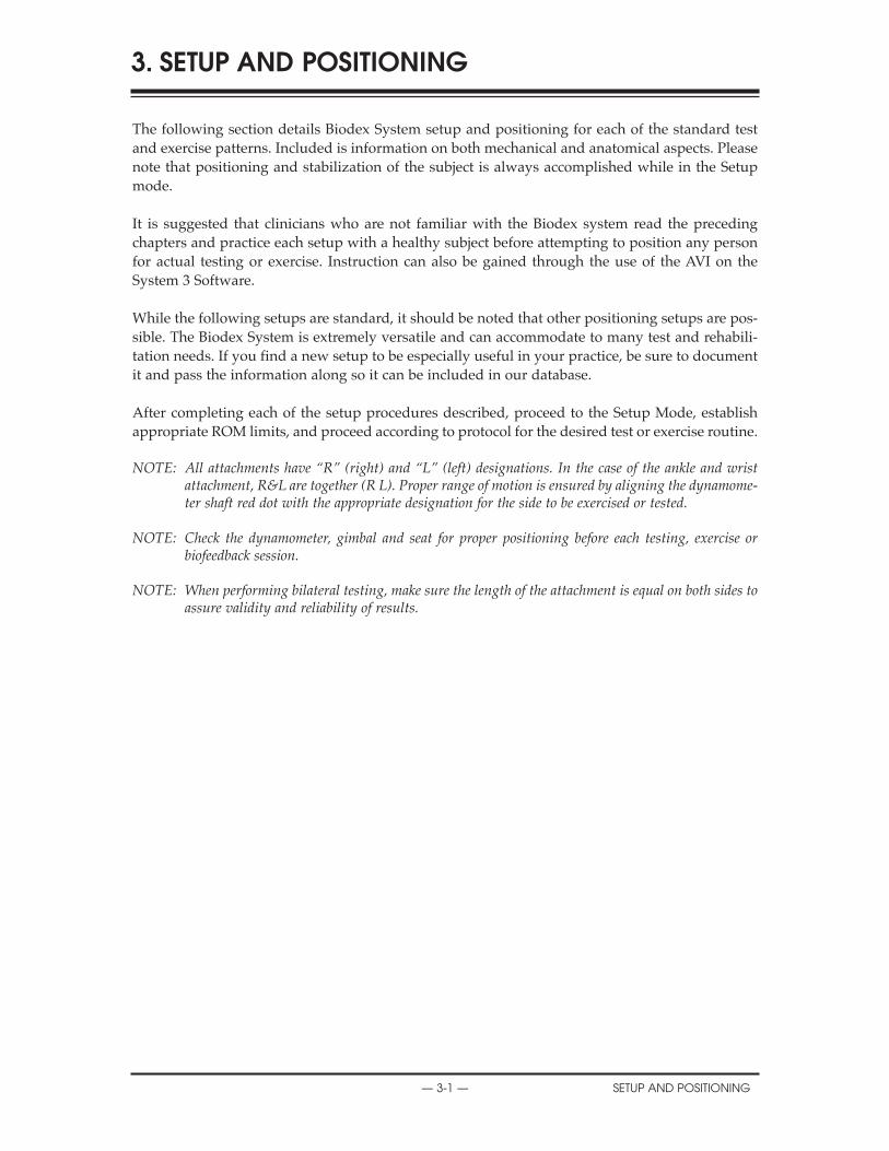
The following section details Biodex System setup and positioning for each of the standard testand exercise patterns. Included is information on both mechanical and anatomical aspects. Pleasenote that positioning and stabilization of the subject is always accomplished while in the Setupmode.
It is suggested that clinicians who are not familiar with the Biodex system read the precedingchapters and practice each setup with a healthy subject before attempting to position any personfor actual testing or exercise. Instruction can also be gained through the use of the AVI on theSystem 3 Software.
While the following setups are standard, it should be noted that other positioning setups are pos-sible. The Biodex System is extremely versatile and can accommodate to many test and rehabili-tation needs. If you find a new setup to be especially useful in your practice, be sure to documentit and pass the information along so it can be included in our database.
After completing each of the setup procedures described, proceed to the Setup Mode, establishappropriate ROM limits, and proceed according to protocol for the desired test or exercise routine.
NOTE: All attachments have “R” (right) and “L” (left) designations. In the case of the ankle and wristattachment, R&L are together (R L). Proper range of motion is ensured by aligning the dynamome-ter shaft red dot with the appropriate designation for the side to be exercised or tested.
NOTE: Check the dynamometer, gimbal and seat for proper positioning before each testing, exercise orbiofeedback session.
NOTE: When performing bilateral testing, make sure the length of the attachment is equal on both sides toassure validity and reliability of results.
3. SETUP AND POSITIONING
— 3-1 — SETUP AND POSITIONING
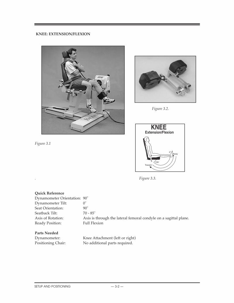
KNEE: EXTENSION/FLEXION
Figure 3.2.
Figure 3.1
. Figure 3.3.
Quick Reference
Dynamometer Orientation: 90˚Dynamometer Tilt: 0˚Seat Orientation: 90˚Seatback Tilt: 70 - 85˚Axis of Rotation: Axis is through the lateral femoral condyle on a sagittal plane.Ready Position: Full Flexion
Parts Needed
Dynamometer: Knee Attachment (left or right)Positioning Chair: No additional parts required.
SERVICE PROCEDURES
SETUP AND POSITIONING — 3-2 —
0
135
Toward
Away

KNEE EXTENSION/FLEXION
Because of multiple factors such as stability through mostly ligamentous and muscular support,the bearing of high forces, and the fact that it is located between the body’s two longest lever arms,the knee is one of the most commonly injured joints in the body. The knee is also the most com-monly tested and rehabilitated joint on the Biodex System.
NOTE: Ensure finger guards are securely in place.
NOTA: S’assurer que le doigtier est bien en place lorsqu’on utilise cet accessoire.
Setup and Positioning
(Starting Movement: Away/Extension)1. Seat patient on chair.2. Rotate chair to 90 degrees.3. Rotate dynamometer to 90 degrees. Slide dynamometer along travel to position outside leg to
be tested or exercised.4. Attach knee attachment to dynamometer. Align dynamometer shaft red dot with red dot on
attachment.5. Move patient into position.6. Align patient knee axis of rotation with dynamometer shaft. Raise/lower seat or move patient
toward/away from dynamometer to fine adjust.7. Adjust knee attachment so that it is proximal to medial malleoli. Secure with strap.
NOTE: Moving the pad proximally has been demonstrated to decrease anterior tibular translation.
8. Stabilize patient with shoulder, waist and thigh straps. 9. Set ROM stops.
Opposite Side
1. Unstrap patient’s knee from attachment and thigh strap.2. With patient remaining in chair, slide chair back away from dynamometer.3. Press Hold button to retain dynamometer shaft position. Remove attachment. Get knee
attachment for opposite side.4. Rotate dynamometer to 90 degrees on opposite side. Slide dynamometer to opposite side of
patient.5. Attach knee attachment to dynamometer. Align dynamometer shaft red dot with red dot on
attachment.6. Move patient into position.7. Align patient knee axis of rotation with dynamometer shaft. Raise/lower seat or move patient
toward/away from dynamometer to fine adjust.8. Adjust knee attachment so that it is proximal to medial malleoli. Secure with strap.9. Stabilize patient with shoulder, waist and thigh straps.10. Reset ROM stops.
X
— 3-3 — SETUP AND POSITIONING
!
!
X
SETUP AND POSITIONING — 3-4 —
Clinical Applications of Biodex Operating Modes
Isokinetic Mode1. The isokinetic mode may be used at high speeds to simulate functional or athletic activities.
2. The isokinetic mode may be used for bi-directional velocities (i.e., during early ACL recon-struction rehabilitation, the hamstrings may be worked at low speeds and the quadriceps athigh speeds. At end stage rehab, the quads may be worked at low speeds and the hamstringsat high speeds).
Passive Mode1. The passive mode is frequently used post-operatively, especially with anterior cruciate liga-
ment repairs, abrasion arthroplasties, and total knee replacements, for the benefits of contin-uous passive motion.
2. The passive mode may be used to move the limb in one direction and concentrically assist oreccentrically resist in the other direction (i.e., in early rehab for ACL reconstructions, the limbmay be moved passively through partial range extension. The subject may then assist or resistflexion with voluntary effort.
3. The passive mode may be used for active-assisted exercise (i.e., a subject status post medialmeniscectomy may be moved passively through a range where voluntary effort cannot beexerted and may assist in the parts of the range where able).
4. The passive mode may be used to do eccentric/concentric contractions. After an ACL recon-struction, the hamstrings may be worked eccentrically and concentrically through limitedrange and then through the full range. At end stage rehab, the quadriceps may be worked atthe end of the range, both concentrically and eccentrically, to decrease an extensor lag.
Isometric Mode1. The isometric mode may be used with pre- or post-operative subjects or when pain is a factor.
Isotonic Mode1. Prior to performing traditional isotonics on weight equipment, a patient can perform various
contractions isotonically to ensure proper muscular function.
2. Since a pre-load is required, gravity and momentum play a minimal role in exercise. Thisensures patient compliance.
Reactive Eccentric Mode1. The Reactive Eccentric mode may be used maximally or submaximally to replicate function-
al activities. The role of submaximal eccentrics has been greatly overlooked. With ACL recon-structions, the hamstrings may be worked through full range of motion eccentrically withsubmaximal effort.
2. Specific areas of weakness in a range of motion such as quadriceps extensor lag may beworked eccentrically at the last 30˚ of extension with submaximal effort.
3. Submaximal eccentrics may be used to protect injured or grafted structures (i.e., post-opera-tively, subjects may exercise in the eccentric mode with the torque limits set very low. If thesubject were to exceed the set torque limit, the input shaft would stop).
Additional Comments1. The pause may be used for passive stretching or to perform contract/relax for the facilitation
of motion. This is especially important after a total knee replacement when early motion iscrucial. The pause may also be used when working in the passive mode to do eccentric or non-reciprocal contractions.
2. All modes may be used in combination with electrical stimulation.
3. With anterior cruciate ligament rehabilitation, pay close attention to tibial pad placement.Research has shown that while working the quadriceps, less stress is placed on the ACL whenthe pad is placed in the proximal position. For hamstring work, place the pad in a more dis-tal position.
4. Subjects may be worked through only a partial range using the percent range dials. This isimportant to assist with focusing on range of motion specific weakness.
5. When treating the knee, total leg strength should be considered, especially the strength of hipabductors and adductors.
6. It has been found that most ACL injuries occur during deceleration, therefore, eccentric exer-cise is an important part of the rehabilitation process.
7. Because a subject is proximally stabilized, very little substitution will occur. Proximal stabi-lization lends itself to joint isolation.
8. The seatback of the positioning chair may be adjusted to accommodate any hip angle the clin-ician finds appropriate. Typically, a 70º incline will place the hamstring and quadraceps in anoptimal length-tension relationship allowing for improved muscle output.
9. Increasing speeds (180˚-300˚/sec.) decreases anterior tibial translation, and joint compressive forces.Important applications for rehabilitating anterior cruciate injuries and patellofemoral dysfunction.
X
— 3-5 — SETUP AND POSITIONING
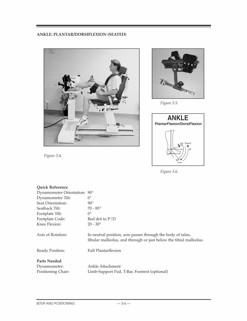
ANKLE: PLANTAR/DORSIFLEXION (SEATED)
Figure 3.5.
Figure 3.4.
Figure 3.6.
Quick Reference
Dynamometer Orientation: 90°Dynamometer Tilt: 0°Seat Orientation: 90°Seatback Tilt: 70 - 85°Footplate Tilt: 0°Footplate Code: Red dot to P/DKnee Flexion: 20 - 30°
Axis of Rotation: In neutral position, axis passes through the body of talus, fibular malleolus, and through or just below the tibial malleolus.
Ready Position: Full Plantarflexion
Parts Needed
Dynamometer: Ankle AttachmentPositioning Chair: Limb-Support Pad, T-Bar, Footrest (optional)
X
SETUP AND POSITIONING — 3-6 —
30
0
50
PlantarFlexion/DorsiFlexion
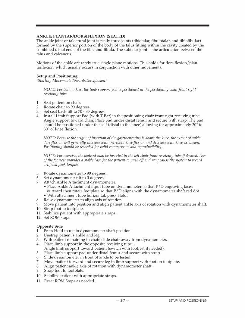
ANKLE: PLANTAR/DORSIFLEXION (SEATED)The ankle joint or talocrural joint is really three joints (tibiotalar, fibulotalar, and tibiofibular)formed by the superior portion of the body of the talus fitting within the cavity created by thecombined distal ends of the tibia and fibula. The subtalar joint is the articulation between thetalus and calcaneus.
Motions of the ankle are rarely true single plane motions. This holds for dorsiflexion/plan-tarflexion, which usually occurs in conjunction with other movements.
Setup and Positioning (Starting Movement: Toward/Dorsiflexion)
NOTE: For both ankles, the limb support pad is positioned in the positioning chair front right receiving tube.
1. Seat patient on chair.2. Rotate chair to 90 degrees.3. Set seat back tilt to 70 - 85 degrees.4. Install Limb Support Pad (with T-Bar) in the positioning chair front right receiving tube.
Angle support toward chair. Place pad under distal femur and secure with strap. The pad should be positioned under the calf (distal to the knee) allowing for approximately 20° to 30° of knee flexion.
NOTE: Because the origin of insertion of the gastrocnemius is above the knee, the extent of ankle dorsiflexion will generally increase with increased knee flexion and decrease with knee extension. Positioning should be recorded for valid comparisons and reproducibility.
NOTE: For exercise, the footrest may be inserted in the left chair front receiving tube if desired. Use of the footrest provides a stable base for the patient to push off and may cause the system to record artificial peak torques.
5. Rotate dynamometer to 90 degrees.6. Set dynamometer tilt to 0 degrees.7. Attach Ankle Attachment dynamometer.
• Place Ankle Attachment input tube on dynamometer so that P/D engraving faces outward then rotate footplate so that P/D aligns with the dynamometer shaft red dot.
• With attachment tube horizontal, press Hold.8. Raise dynamometer to align axis of rotation.9. Move patient into position and align patient ankle axis of rotation with dynamometer shaft.10. Strap foot to footplate.11. Stabilize patient with appropriate straps.12. Set ROM stops
Opposite Side1. Press Hold to retain dynamometer shaft position.2. Unstrap patient’s ankle and leg.3. With patient remaining in chair, slide chair away from dynamometer.4. Place limb support in the opposite receiving tube .
Angle limb support toward patient (switch with footrest if needed). 5. Place limb support pad under distal femur and secure with strap.6. Slide dynamometer in front of ankle to be tested. 7. Move patient forward and secure leg in limb support with foot on footplate.8. Align patient ankle axis of rotation with dynamometer shaft.9. Strap foot to footplate.10. Stabilize patient with appropriate straps.11. Reset ROM Stops as needed.
X
— 3-7 — SETUP AND POSITIONING

X
SETUP AND POSITIONING — 3-8 —
Clinical Applications of Biodex Operating Modes
Isokinetic Mode1. The isokinetic mode may be used at bi-directional velocities. This is especially important at
the ankle complex where the muscular strength is unbalanced. Many clinicians work the plantarflexors at slower speeds and the dorsiflexors at higher speeds.
Passive Mode1. The passive mode may be used after a period of immobilization for the benefits of
continuous passive motion.
2. The passive mode may be used to perform non-reciprocal contractions (e.g., many times the plantarflexors are considered to be the more essential muscle group to be rehabilitated after injury. The plantar flexors may be worked both concentrically and eccentrically in the passive mode.
Isometric Mode1. Multi-angle isometrics may be used pre- and post-operatively or after periods of immobilization.
Isotonic Mode1. In later phases of rehab, perform various concentric contractions to isolate one muscle
group only.
2. Set torque limit higher for plantarflexors and lower for dorsiflexors to ensure fatigue time remains constant.
Reactive Eccentric Mode1. The eccentric mode may be used to strengthen the musculotendinous junction. Many times
injuries occur at the ankle secondary to eccentric loading to failure. It may be especially important to rehab athletes in the eccentric mode.
Additional Comments1. The ankle is known to be unstable in the plantarflexed position, an important fact to keep
in mind when dealing with athletes.
2. It has been stated that peroneal and dorsiflexor strengthening may help in resisting an inversion/plantarflexion injury.
3. The gait cycle may be simulated by using the passive mode in this sequence:• Subject works eccentric dorsiflexion (heelstrike).• Subject works eccentric plantarflexion (midstance).• Subject works concentric plantarflexion (toe off).• Subject works concentric dorsiflexion motion (swing phase).
4. It has been suggested for the subject to work barefoot with a piece of malleable material, or a folded towel, between the foot and the attachment to work the intrinsics of the foot.
5. When rehabilitating the ankle, it is important to consider total leg strength.
6. If swelling is a consideration, the dynamometer may be raised. If cramping of the lower leg musculature is a problem, the dynamometer may be lowered to bring the ankle into a more dependent position to allow enhanced blood flow.
7. Optionally, the seatback can be placed in the horizontal position to allow testing or exercise in the supine position.
— 3-9 — SETUP AND POSITIONING
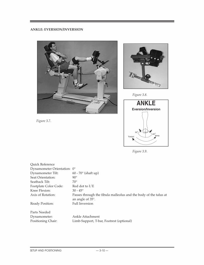
ANKLE: EVERSION/INVERSION
Figure 3.8.
Figure 3.7.
Figure 3.9.
Quick ReferenceDynamometer Orientation: 0°Dynamometer Tilt: 60 - 70° (shaft up)Seat Orientation: 90°Seatback Tilt: 70°Footplate Color Code: Red dot to I/EKnee Flexion: 30 - 45°Axis of Rotation: Passes through the fibula malleolus and the body of the talus at
an angle of 35°.Ready Position: Full Inversion
Parts NeededDynamometer: Ankle AttachmentPositioning Chair: Limb-Support, T-bar, Footrest (optional)
X
SETUP AND POSITIONING — 3-10 —
5540Away
Toward
Eversion/Inversion

GENERAL MAINTENANCE
— 3-11 — SETUP AND POSITIONING
ANKLE: INVERSION/EVERSION (SEATED)
The ankle is vulnerable to inversion injuries making injuries to the anterior talofibular complexa common occurrence that may be difficult to rehabilitate.
Recurrent injuries to the lateral ligamentous complex have been shown to decrease propriocep-tion of the ankle and athletic performance.
Setup and Positioning
(Starting Movement: Away/Eversion)
1. Seat patient on chair. 2. Install Limb Support Pad (with T-Bar) in chair front receiving tube for side to be exercised
or tested. Angle Limb Support toward chair. Place pad under distal femur and secure with strap.
3. Attach input tube to dynamometer.• I/E engraving faces outward. • Right Ankle and Left Ankle are oriented with input shaft straight up. Align shaft red dot
with R L.• With attachment vertical, press Hold.
4. Install footplate. Red dot to I/E.5. Adjust the footplate angle to align red dot with “I” marker.6. Rotate dynamometer to 0 degrees and position in line with limb support.7. Lower dynamometer all the way down in pedestal.8. Rotate chair to 90 degrees.9. Set dynamometer tilt to 60-70 degrees (see label on dynamometer face).10. Set seat back tilt to 70 degrees.11. Move patient into position and align ankle axis of rotation with dynamometer shaft.12. Raise chair as needed to fine adjust axis of rotation.13. Strap foot to footplate and stabilize patient with appropriated straps.14. Set ROM Stops.15. Ensure the subject’s lower leg is parallel to the floor.
Opposite Ankle
1. Press Hold to retain dynamometer shaft position.2. Unstrap patient’s ankle and leg.3. With patient remaining in chair, slide chair away from dynamometer.4. Place limb support in the opposite receiving tube. Angle limb support toward chair.5. Slide dynamometer to opposite position.6. Move patient forward into position and secure leg in limb support with foot on footplate.
Align ankle axis of rotation with dynamometer shaft.7. Strap foot to footplate and stabilize patient with appropriate straps.8. Reset ROM Stops.

Clinical Applications of Biodex Operating Modes
Isokinetic Mode1. The isokinetic mode may be set bi-directionally. In the case of a lateral sprain, evertors may
be set at relatively low speeds and invertors at higher speeds. Range of motion should be limited as warranted.
2. The concentric/eccentric setting may be used in the later stages of rehab for muscle strengthening.
Passive Mode1. The passive mode may be used after immobilization for the benefits of continuous passive
motion. The passive mode may also be used to assist with neurologic retraining in the first few weeks after injury or surgery.
2. The passive mode may be used in combination with electric stimulation, ice and elevation for acute ankle sprains to help reduce swelling.
3. The passive mode may be used after a lateral ligamentous sprain to evert submaximally andpassively invert. Inversion may be limited by ROM Limit Set buttons or percent range dials if warranted.
4. The passive mode may be used after lateral ligamentous sprain to work the evertors both concentrically and eccentrically. Range of motion may be limited as stated above.
Isometric Mode1. Multi-angle isometrics may be performed in the isometric mode. Strength carry-over has
been found to be plus or minus ten degrees of the ankle exercise performed. Isometrics may be used to stress either the agonist or antagonist.
Isotonic1. Set torque limits accordingly to ensure adequate force production throughout the ROM.
Reactive Eccentric Mode1. The eccentric mode may be used to perform maximal or submaximal activities, develop
preprioception, and to simulate function or sports activities.
Additional Comments1. Ankle inversion injury has been noted to be caused by eccentric peroneal activity to failure.
2. A piece of malleable foam, or a folded towel, may be placed between the subject’s bare foot and the attachment to work the intrinsics of the foot during rehabilitation.
3. Athletes who have poor static balance have been found to have weak evertors. Evertor strengthening may be helpful.
4. Consider the importance of total leg strength in the process of rehabilitating the ankle.
5. The ankle may be rehabilitated in an elevated position if edema is present.
6. If cramping is a problem, the dynamometer may be lowered to bring the ankle into a more dependent position, allowing enhanced blood flow.
7. The seat tilt may be placed in the horizontal plane to allow testing in the supine position. This may require a slight adjustment of the dynamometer.
SERVICE PROCEDURES
SETUP AND POSITIONING — 3-12 —
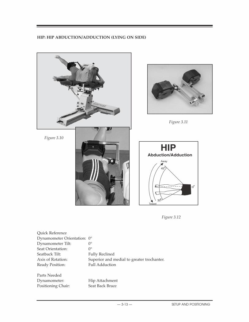
REPLACEMENT PARTS
— 3-13 — SETUP AND POSITIONING
hIP: hIP ABDUCTION/ADDUCTION (LYING ON SIDE)
Figure 3.11
Figure 3.10
Figure 3.12
Quick ReferenceDynamometer Orientation: 0°Dynamometer Tilt: 0°Seat Orientation: 0°Seatback Tilt: Fully ReclinedAxis of Rotation: Superior and medial to greater trochanter.Ready Position: Full Adduction
Parts NeededDynamometer: Hip AttachmentPositioning Chair: Seat Back Brace
45
30
0
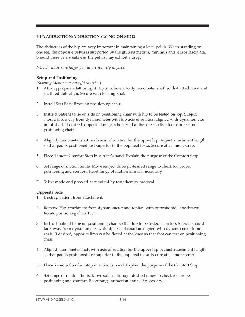
hIP: ABDUCTION/ADDUCTION (LYING ON SIDE)
The abductors of the hip are very important in maintaining a level pelvis. When standing onone leg, the opposite pelvis is supported by the gluteus medius, minimus and tensor fascialata.Should there be a weakness, the pelvis may exhibit a drop.
NOTE: Make sure finger guards are securely in place.
Setup and Positioning
(Starting Movement: Away/Abduction)1. Affix appropriate left or right Hip attachment to dynamometer shaft so that attachment and
shaft red dots align. Secure with locking knob.
2. Install Seat Back Brace on positioning chair.
3. Instruct patient to lie on side on positioning chair with hip to be tested on top. Subject should face away from dynamometer with hip axis of rotation aligned with dynamometer input shaft. If desired, opposite limb can be flexed at the knee so that foot can rest on positioning chair.
4. Align dynamometer shaft with axis of rotation for the upper hip. Adjust attachment length so that pad is positioned just superior to the popliteal fossa. Secure attachment strap.
5. Place Remote Comfort Stop in subject’s hand. Explain the purpose of the Comfort Stop.
6. Set range of motion limits. Move subject through desired range to check for proper positioning and comfort. Reset range of motion limits, if necessary.
7. Select mode and proceed as required by test/therapy protocol.
Opposite Side
1. Unstrap patient from attachment.
2. Remove Hip attachment from dynamometer and replace with opposite side attachment. Rotate positioning chair 180°.
3. Instruct patient to lie on positioning chair so that hip to be tested is on top. Subject should face away from dynamometer with hip axis of rotation aligned with dynamometer input shaft. If desired, opposite limb can be flexed at the knee so that foot can rest on positioning chair.
4. Align dynamometer shaft with axis of rotation for the upper hip. Adjust attachment length so that pad is positioned just superior to the popliteal fossa. Secure attachment strap.
5. Place Remote Comfort Stop in subject’s hand. Explain the purpose of the Comfort Stop.
6. Set range of motion limits. Move subject through desired range to check for proper positioning and comfort. Reset range or motion limits, if necessary.
X
SETUP AND POSITIONING — 3-14 —
SCHEMATICS
— 3-15 — SETUP AND POSITIONING
Clinical Applications
1. The passive mode may be used for the benefits of continuous passive motion after a total hip replacement.
NOTE: Progress hip range of motion only under the direct supervision of a physician.
NOTA: Avancer en flexion seulement sous la surveillance d’un médecin.
2. Many times in cases of degenerative joint disease (DJD) the cartilage in the area does not undergo the absorption and squeezing out of synovial fluid necessary for adequate nutrition. The passive mode may be used to assist this process, especially for older persons who use their joints less frequently and through smaller ranges of motion. The passive mode may also be used as a preventative measure to reduce capsular tightening at the hip.
!
!

hIP: EXTENSION/FLEXION (SUPINE)
Figure 3.14.
Figure 3.13.
Figure 3.15.
Quick Reference
Dynamometer Orientation: 0°Dynamometer Tilt: 0°Seat Orientation: 0°Seatback Tilt: Fully ReclinedAxis of Rotation: Superior and anterior to greater trochanter when limb is in
neutral position.Ready Position: Neutral Extension
Parts Needed
Dynamometer: Hip AttachmentPositioning Chair: Footrest (optional)
Seat Back Brace
CONTENTS
SETUP AND POSITIONING — 3-16 —
0
120
Away
hIP: EXTENSION/FLEXION (SUPINE)The hip is a multiaxial ball and socket joint which consists of the articulation between the headof the femur and acetabulum of the os coxae.
There are a number of bursae at the hip. The iliopectineal bursa covers the anterior aspect of thehip joint and inflammation may cause anterior hip pain.
NOTE: Ensure finger guards are securely in place.
Setup and Positioning(Starting Movement: Away/Flexion)
1. Affix appropriate left or right Hip attachment to dynamometer shaft so that attachment andshaft red dots align. Secure with locking knob.
2. Install Seat Back Brace on positioning chair.
3. Instruct patient to lie supine on positioning chair with hip to be tested closest to the dynamometer. Adjust chair and dynamometer so that shaft aligns with the axis of rotation of the hip. The axis of rotation of the hip in this pattern is slightly superior and anterior to the greater trochanter.
4. Adjust Hip Attachment length so that thigh support is just superior to the popliteal fossa. Position pad anteriorly on the thigh and secure by wrapping the padded strap snuggly around the thigh.
5. Place Remote Comfort Stop in subject’s hand. Explain the purpose of the Comfort Stop.
6. Set range of motion limits. Move patient through range of motion to check for proper alignment and subject comfort. Make sure straps do not impede range of motion. Readjust ROM limits, if necessary.
7. Select mode and proceed as required by test/therapy protocol.
Opposite Side1. Unstrap patient from attachment.
2. Remove attachment from dynamometer and replace with opposite side attachment.
3. Rotate positioning chair 180°.
4. Instruct patient to reposition and lie supine on chair. Hip to be tested should be closest to the dynamometer. Adjust chair and dynamometer so that shaft aligns with the axis of rotation of the hip. The axis of rotation of the hip in this pattern is slightly superior and anterior to the greater trochanter.
5. Adjust Hip attachment length so that thigh support is just superior to the popliteal fossa. Secure Hip attachment strap.
6. Place Remote Comfort Stop in subject’s hand. Explain the purpose of the Comfort Stop.
7. Reset range of motion limits. Move patient through range of motion to check for proper alignment and subject comfort. Make sure straps do not impede range of motion. Readjust ROM limits, if necessary.
!
TROUBLESHOOTING
— 3-17 — SETUP AND POSITIONING
Clinical Applications of Biodex Operating Modes
Passive Mode
1. The passive mode may be used for the benefits of continuous passive motion after a total hip replacement.
NOTE: Progress flexion only under the direct supervision of a physician.
NOTA: Advancer en flexion seulement sous la surveillance d’un médecin.
2. Many times in cases of degenerative joint disease (DJD) the cartilage in the area does not undergo the absorption and squeezing out of synovial fluid necessary for adequate nutrition. The passive mode may be used for this problem, especially for older persons who use their joints less frequently and through smaller ranges of motion. The passive mode may also be used as a preventative measure to reduce capsular tightening at the hip.
CONTENTS
SETUP AND POSITIONING — 3-18 —

CONTENTS
— 3-19 — SETUP AND POSITIONING
ShOULDER: FLEXION/EXTENSION (SEATED)
Figure 3.17.
Figure 3.16.
Figure 3.18.
Quick Reference
Dynamometer Orientation: 0˚Dynamometer Tilt: 0˚Seat Orientation: 15˚Seatback Tilt: 70 - 85˚Axis of Rotation: Compromise axis is acromial process in the sagittal plane.Ready Position: Full Extension
Parts Needed
Dynamometer: Shoulder/Elbow Adapter (remove cuff), Shoulder AttachmentPositioning Chair: Footrest (optional)
0
60
180
Away
Toward
Shoulder/Elbow Adapter
Shoulder Attachment
REPLACEMENT PARTS
SETUP AND POSITIONING — 3-20 —
ShOULDER: EXTENSION/FLEXION (SEATED)
Shoulder extension/flexion is a motion that is usually initiated early in the rehabilitation process,however, clinicians must be careful not to cause impingement. An impingement sign is producedwhen the shoulder is fully flexed and there is jamming of the greater tuberosity against the anteroinferior surface of the acromion. For this reason, the clinician may want to limit flexion range ofmotion in the early stages of the rehabilitation process.
Setup and Positioning
(Starting Movement: Away/Extension)
NOTE: This pattern may be accomplished with the positioning chair seatback reclined to any positionwhich provides for both subject comfort and proper alignment of the anatomical axis. (The seat-back and dynamometer tilt must, however, be set parallel.)
1. Seat patient on chair.2. Attach Shoulder/Elbow Adapter to dynamometer (remove cuff). Insert Shoulder Attachment
into Adapter.3. Align Shaft red dot with R or L and move attachment to almost full extension. Press Hold.4. Slide dynamometer along travel to position outside of shoulder to be tested.5. Rotate dynamometer to 0 degrees.6. Tilt dynamometer to 0 degrees7. Rotate chair to 15 degrees.8. Move patient into position. Align patient axis of rotation. Raising dynamometer or tilting seat-
back can accommodate various size patients.9. Check for proper ROM. Keep handgrip loose during motion to allow for the compromising
positions of the glenoid humeral joint as it goes through the motions.10. Stabilize patient with shoulder, waist and thigh straps.11. Set ROM stops.
Opposite Side
1. Press Hold.2. With patient remaining in chair, slide chair back along travel.3. Remove attachment and rotate it 180 degrees. Align Shaft red dot with R or L.4. Move attachment to almost full extension.5. Move dynamometer to opposite position. Dynamometer rotation remains at 0 degrees.6. Rotate chair to opposite 15 degrees.7. Move patient into position. Align patient axis of rotation. Raising dynamometer or tilting seat-
back can accommodate various size patients.8. Check for proper ROM. Keep handgrip loose during motion to allow for the compromising
positions of the glenoid humeral joint as it goes through the motions.9. Stabilize patient with shoulder, waist and thigh straps.10. Reset ROM stops.
— 3-21 — SETUP AND POSITIONING
REPLACEMENT PARTS
Clinical Applications of Biodex Operating Modes
Isokinetic Mode1. The isokinetic mode may be used bi-directionally to focus on one specific muscle group
(i.e., in an impingement syndrome the flexors may be worked at a fast speed through alimited range and the extensors at a lower speed).
Passive Mode1. The passive mode may be used initially for the benefits of continuous passive motion. It has
been suggested that early re-establishment of neural pathways without stressing an inflamed capsule is essential.
2. It has been suggested to increase anterior shoulder flexibility in the acute phase of a rotator cuff strain without offering resistance. The passive mode may be used to carry the limb into the flexed position. The subject may be instructed to assist the extensors as the arm is moved in the away direction.
3. It has been suggested by some clinicians that submaximal eccentrics that can be performed in the passive mode may be used to treat subjects with bicipital tendinitis.
4. With adhesive capsulitis, the subject may be placed in the passive mode with a four second pause at end range.
Isometric Mode1. Isometrics may be used immediately pre- and post-operatively. Multi-angle isometrics are
recommended to achieve physiological overflow into that portion of the range which has not been exercised.
Isotonic1. Set torque limits accordingly to ensure adequate force production throughout the ROM.
Additional Comments1. With impingement syndrome and anterior subluxation, it has been recommended to initially
limit motion to under 90 degrees and progress slowly past this point.
2. It is important to consider that glenohumeral motion requires a coordinated effort between the deltoid and the rotator cuff musculature. Working the anterior deltoid non-reciprocally will strengthen this muscle concentrically and eccentrically.
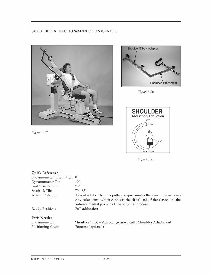
REPLACEMENT PARTS
SETUP AND POSITIONING — 3-22 —
ShOULDER: ABDUCTION/ADDUCTION (SEATED)
Figure 3.20.
Figure 3.19.
Figure 3.21.
Quick Reference
Dynamometer Orientation: 0˚Dynamometer Tilt: 10˚Seat Orientation: 75˚Seatback Tilt: 70 - 85˚Axis of Rotation: Axis of rotation for this pattern approximates the axis of the acromio
clavicular joint, which connects the distal end of the clavicle to the anterior medial portion of the acromial process.
Ready Position: Full adduction
Parts Needed
Dynamometer: Shoulder/Elbow Adapter (remove cuff), Shoulder AttachmentPositioning Chair: Footrest (optional)
180
0
75
Away
Toward
Shoulder/Elbow Adapter
Shoulder Attachment

REPLACEMENT PARTS
— 3-23 — SETUP AND POSITIONING
ShOULDER: ABDUCTION/ADDUCTION (SEATED)
The shoulder complex is made up of multiple linkages. These include the glenohumeral joint,acromioclavicular joint, sternoclavicular joint, and scapulothoracic articulation. The glenohumer-al joint is the most mobile joint in the body with global freedom. Because of this, stability is sacri-ficed. Only a little more than 1/3 of the head of the humerus makes contact with the glenoidfos-sa at any one time.
Abduction/adduction is usually one of the last motions exercised in rehabilitation of the shoul-der. The clinician must exercise great care in order to avoid impingement.
Setup and Positioning
(Starting Movement: Away/Abduction)
NOTE: This pattern may be accomplished with the seatback reclined to any position which provides forboth patient comfort and proper alignment of the anatomical axis. The seatback and dynamometertilt must, however, be set to the same angle.
1. Seat patient on chair. 2. Attach Shoulder/Elbow Adapter to dynamometer (remove cuff). Insert Shoulder Attachment
into Adapter.3. Align Shaft red dot with R or L and move attachment to almost full abduction. Press Hold.4. Rotate chair to 75 degrees.5. Rotate dynamometer to 0 degrees.6. Raise dynamometer.7. Tilt dynamometer to 10 degrees.8. Move patient into position (patient is facing away from dynamometer). Slide dynamometer
along travel to align axis of rotation.9. Check for proper ROM. Keep handgrip loose during motion to allow for the compromising
positions of the glenoid humeral joint as it goes through the motions.10. Stabilize patient with shoulder and waist straps.11. Set ROM stops.
Opposite Side
1. With patient remaining in chair, slide chair back away from dynamometer.2. Remove attachment and rotate it 180 degrees opposite. Align Shaft red dot with R or L.3. Move attachment to almost full abduction. Press Hold.4. Rotate chair to opposite 75 degrees.5. Move dynamometer to opposite position. Dynamometer orientation remains at 0 degrees. 6. Move patient into position (patient is facing away from dynamometer). Slide dynamometer
along travel to align axis of rotation.7. Check for proper ROM. Keep handgrip loose during motion to allow for the compromising
positions of the glenoid humeral joint as it goes through the motions.8. Stabilize patient with shoulder and waist straps.9. Reset ROM stops.
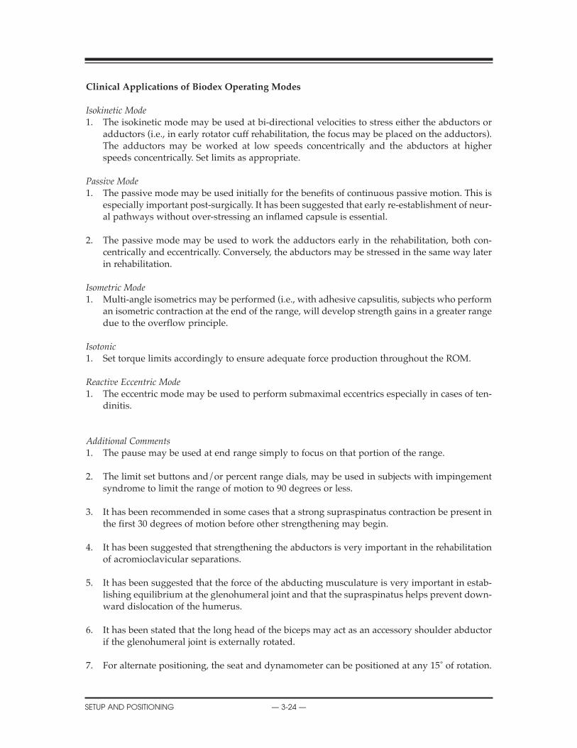
SCHEMATICS
SETUP AND POSITIONING — 3-24 —
Clinical Applications of Biodex Operating Modes
Isokinetic Mode1. The isokinetic mode may be used at bi-directional velocities to stress either the abductors or
adductors (i.e., in early rotator cuff rehabilitation, the focus may be placed on the adductors).The adductors may be worked at low speeds concentrically and the abductors at higherspeeds concentrically. Set limits as appropriate.
Passive Mode1. The passive mode may be used initially for the benefits of continuous passive motion. This is
especially important post-surgically. It has been suggested that early re-establishment of neur-al pathways without over-stressing an inflamed capsule is essential.
2. The passive mode may be used to work the adductors early in the rehabilitation, both con-centrically and eccentrically. Conversely, the abductors may be stressed in the same way laterin rehabilitation.
Isometric Mode1. Multi-angle isometrics may be performed (i.e., with adhesive capsulitis, subjects who perform
an isometric contraction at the end of the range, will develop strength gains in a greater rangedue to the overflow principle.
Isotonic1. Set torque limits accordingly to ensure adequate force production throughout the ROM.
Reactive Eccentric Mode1. The eccentric mode may be used to perform submaximal eccentrics especially in cases of ten-
dinitis.
Additional Comments1. The pause may be used at end range simply to focus on that portion of the range.
2. The limit set buttons and/or percent range dials, may be used in subjects with impingementsyndrome to limit the range of motion to 90 degrees or less.
3. It has been recommended in some cases that a strong supraspinatus contraction be present inthe first 30 degrees of motion before other strengthening may begin.
4. It has been suggested that strengthening the abductors is very important in the rehabilitationof acromioclavicular separations.
5. It has been suggested that the force of the abducting musculature is very important in estab-lishing equilibrium at the glenohumeral joint and that the supraspinatus helps prevent down-ward dislocation of the humerus.
6. It has been stated that the long head of the biceps may act as an accessory shoulder abductorif the glenohumeral joint is externally rotated.
7. For alternate positioning, the seat and dynamometer can be positioned at any 15˚ of rotation.
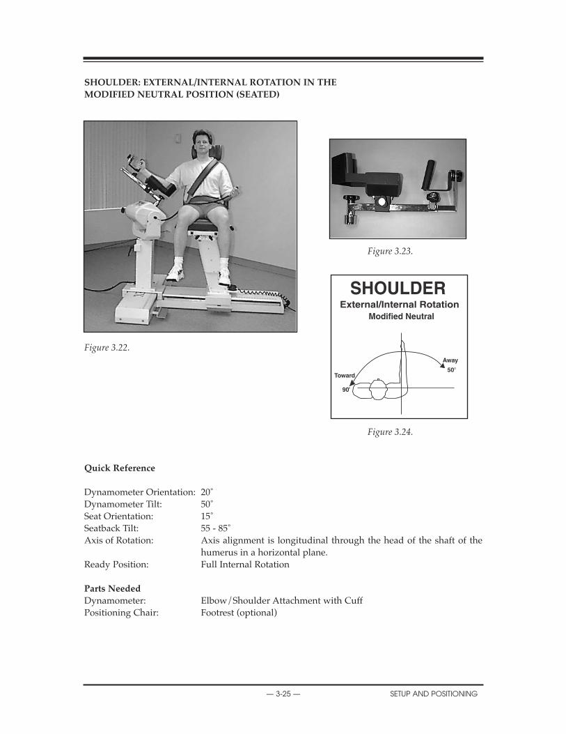
ShOULDER: EXTERNAL/INTERNAL ROTATION IN ThE
MODIFIED NEUTRAL POSITION (SEATED)
Figure 3.23.
Figure 3.22.
Figure 3.24.
Quick Reference
Dynamometer Orientation: 20˚Dynamometer Tilt: 50˚Seat Orientation: 15˚Seatback Tilt: 55 - 85˚Axis of Rotation: Axis alignment is longitudinal through the head of the shaft of the
humerus in a horizontal plane.Ready Position: Full Internal Rotation
Parts Needed
Dynamometer: Elbow/Shoulder Attachment with CuffPositioning Chair: Footrest (optional)
Away
50Toward
90
CONTENTS
— 3-25 — SETUP AND POSITIONING
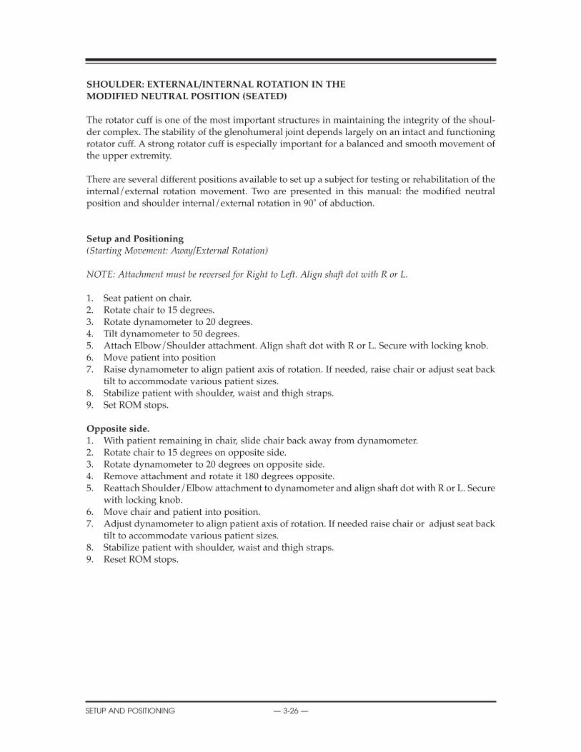
ShOULDER: EXTERNAL/INTERNAL ROTATION IN ThE MODIFIED NEUTRAL POSITION (SEATED)
The rotator cuff is one of the most important structures in maintaining the integrity of the shoul-der complex. The stability of the glenohumeral joint depends largely on an intact and functioningrotator cuff. A strong rotator cuff is especially important for a balanced and smooth movement ofthe upper extremity.
There are several different positions available to set up a subject for testing or rehabilitation of theinternal/external rotation movement. Two are presented in this manual: the modified neutralposition and shoulder internal/external rotation in 90˚ of abduction.
Setup and Positioning(Starting Movement: Away/External Rotation)
NOTE: Attachment must be reversed for Right to Left. Align shaft dot with R or L.
1. Seat patient on chair.2. Rotate chair to 15 degrees.3. Rotate dynamometer to 20 degrees.4. Tilt dynamometer to 50 degrees.5. Attach Elbow/Shoulder attachment. Align shaft dot with R or L. Secure with locking knob.6. Move patient into position7. Raise dynamometer to align patient axis of rotation. If needed, raise chair or adjust seat back
tilt to accommodate various patient sizes.8. Stabilize patient with shoulder, waist and thigh straps.9. Set ROM stops.
Opposite side.1. With patient remaining in chair, slide chair back away from dynamometer.2. Rotate chair to 15 degrees on opposite side.3. Rotate dynamometer to 20 degrees on opposite side.4. Remove attachment and rotate it 180 degrees opposite.5. Reattach Shoulder/Elbow attachment to dynamometer and align shaft dot with R or L. Secure
with locking knob.6. Move chair and patient into position.7. Adjust dynamometer to align patient axis of rotation. If needed raise chair or adjust seat back
tilt to accommodate various patient sizes.8. Stabilize patient with shoulder, waist and thigh straps.9. Reset ROM stops.
CONTENTS
SETUP AND POSITIONING — 3-26 —
Clinical Applications of Biodex Operating Modes
Isokinetic Mode1. The isokinetic mode may be used at bi-directional velocities to stress either the internal rota-
tors or the external rotators. This mode may also be used to replicate function (i.e., the athletemay work the external rotators at lower speeds and the internal rotators at higher speeds toreplicate the throwing motion.)
Passive Mode1. The passive mode may be used initially for the benefits of continuous passive motion. This is
especially important post-surgically. Many clinicians are using this early on post arthroscop-ic surgery.
2. The passive mode may be used to work one muscle group both concentrically and eccentri-cally, (i.e., after an anterior shoulder dislocation, the internal rotators may be worked bothconcentrically and eccentrically through a limited range. With a tear in the posterior rotatorcuff, the internal rotators may also be stressed initially in this way).
Isometric Mode1. Multi-angle isometrics may be performed early in the rehabilitation process or to work near
painful points in the ROM. In this way, strength gains will be made through a portion of theunworked range.
Isotonic1. Set torque accordingly (internal rotation high, external rotation low).2. To increase speed of movement, set torque limits lower.
Reactive Eccentric Mode1. The eccentric mode may be used to perform submaximal eccentrics for the diagnosis of ten-
dinitis (i.e., this technique may be used in cases of supraspinatus tendinitis).
Additional Comments1. Subjects with impingement syndrome may best be worked in the modified neutral position
and not 90 degrees of abduction.
2. A subject may be started in the modified neutral position and be worked into increasingdegrees of abduction as tolerated.
3. Athletes, especially pitchers, may be worked at the 90 degree abduction position and fullexternal rotation since this is a functional position for this group.
4. It has been found that the posterior cuff muscles act to decelerate the arm motion eccentrical-ly during the follow-through phase of throwing. This eccentric motion may be simulated onthe Biodex.
5. Some clinicians have thought of impingement syndrome as an ineffective action of the rotatorcuff musculature. Use the eccentric mode to work on control.
6. As the glenohumeral joint is externally rotated, the anterior capsule undergoes a wringingwhich may cause an inflammatory response in the capsule. External rotation may initially be limited with ROM stop buttons or percent dials to prevent this.
CONTENTS
— 3-27 — SETUP AND POSITIONING
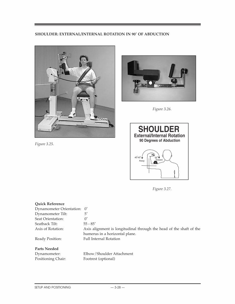
ShOULDER: EXTERNAL/INTERNAL ROTATION IN 90˚ OF ABDUCTION
Figure 3.26.
Figure 3.25.
Figure 3.27.
Quick Reference
Dynamometer Orientation: 0˚Dynamometer Tilt: 5˚Seat Orientation: 0˚Seatback Tilt: 55 - 85˚Axis of Rotation: Axis alignment is longitudinal through the head of the shaft of the
humerus in a horizontal plane.Ready Position: Full Internal Rotation
Parts Needed
Dynamometer: Elbow/Shoulder AttachmentPositioning Chair: Footrest (optional)
CONTENTS
SETUP AND POSITIONING — 3-28 —
5540-45
Away Toward

ShOULDER: EXTERNAL/INTERNAL ROTATION IN 90˚ OF ABDUCTION
The rotator cuff is one of the most important structures in maintaining the integrity of the shoul-der complex. The stability of the glenohumeral joint depends largely on an intact and functioningrotator cuff. A strong rotator cuff is especially important for a balanced and smooth movement ofthe upper extremity.
There are several different positions available to set up a subject for testing or rehabilitation of theinternal/external rotation movement. The setup for this pattern in 90˚ of abduction is as follows.
Setup and Positioning
(Starting Movement: Away/External Rotation)
NOTE: Attachment must be reversed for Right to Left. Align shaft dot with R or L.
1. Seat patient on chair.2. Attach Elbow/Shoulder attachment. Align shaft dot with R or L. Secure with locking knob.3. Tilt dynamometer to 5 degrees.4. Rotate dynamometer to 0 degrees.5. Rotate chair to 0 degrees. 6. Move dynamometer along travel to align axis.7. Tilt seat back to 55 - 85 degrees. If needed, lower seat or adjust seat back tilt to accommodate
various patient sizes.8. Move patient into position and raise dynamometer to align patient axis of rotation. 9. Stabilize patient with shoulder and thigh straps.10. Set ROM stops.
Opposite Side
1. Press Hold.2. With patient remaining in chair, move seat away from dynamometer.3. Remove attachment and align shaft dot with R or L. Shaft will have to rotate 180 degrees.4. Place attachment back onto shaft, secure with locking knob.5. Slide dynamometer to opposite side.6. Rotate chair to 0 degrees opposite position.7. Move patient into position. Raise dynamometer to align patient axis of rotation. 8. Tilt seat back to 55 - 85 degrees. If needed, lower seat or adjust seat back tilt to accommodate
various patient sizes.9. Stabilize patient with shoulder and thigh straps. 10. Reset ROM stops.
CONTENTS
— 3-29 — SETUP AND POSITIONING
Clinical Applications of Biodex Operating Modes
Isokinetic Mode1. The isokinetic mode may be used at bi-directional velocities to stress either the internal rota-
tors or the external rotators. This mode may also be used to replicate function (i.e., the athletemay work the external rotators at lower speeds and the internal rotators at higher speeds toreplicate the throwing motion.)
Passive Mode1. The passive mode may be used initially for the benefits of continuous passive motion. This is
especially important post-surgically. Many clinicians are using this mode one day post-opafter arthroscopic surgery.
2. The passive mode may be used to work one muscle group both concentrically and eccentri-cally, (i.e., after an anterior shoulder dislocation, the internal rotators may be worked bothconcentrically and eccentrically through a limited range. With a tear in the posterior rotatorcuff, the internal rotators may also be stressed initially in this way).
Isometric Mode1. Multi-angle isometrics may be performed early in the rehabilitation process or to work near
painful points in the ROM. In this way, strength gains will be made through a portion of theunworked range.
Isotonic1. To increase speed of movement, set torque limits lower.2. Set torque accordingly (internal rotation high, external rotation low).
Reactive Eccentric Mode1. The eccentric mode may be used to perform submaximal eccentrics for the diagnosis of ten-
dinitis (i.e., this technique may be used in cases of supraspinatus tendinitis).
Additional Comments1. Subjects with impingement syndrome may best be worked in the modified neutral position
and not 90 degrees of abduction.
2. A subject may be started in the modified neutral position and be worked into increasingdegrees of abduction as tolerated.
3. Athletes, especially pitchers, may be worked at the 90 degree abduction position and fullexternal rotation since this is a functional position for this group.
4. It has been found that the posterior cuff muscles act to decelerate the arm motion eccentrical-ly during the follow-through phase of throwing. This eccentric motion may be simulated onthe Biodex.
5. Some clinicians have thought of impingement syndrome as an ineffective action of the rotatorcuff musculature. Use the eccentric mode to work on control.
6. As the glenohumeral joint is externally rotated, the anterior capsule undergoes a wringingwhich may cause an inflammatory response in the capsule. External rotation may initially belimited with ROM stop buttons or percent dials to prevent this.
CONTENTS
SETUP AND POSITIONING — 3-30 —

ShOULDER: DIAGONAL (SEATED)
Figure 3.29
Figure 3.28.
Figure 3.30.
Quick Reference
Dynamometer Orientation: 30˚Dynamometer Tilt: 10 - 35˚Seat Orientation: 0˚Seatback Tilt: 85˚Axis of Rotation: Off axis through the glenohumeral joint.Ready Position: Full Extension
Parts Needed
Dynamometer: Shoulder/Elbow Adapter (remove cuff), Shoulder AttachmentPositioning Chair: Footrest (optional)
CONTENTS
— 3-31 — SETUP AND POSITIONING
0
180
Away
Toward
Shoulder/Elbow Adapter
Shoulder Attachment

ShOULDER: DIAGONAL (SEATED)
Setup and Positioning
(Starting Movement: Away/Flexion)
1. Seat patient on chair2. Attach Shoulder/Elbow Adapter to dynamometer (remove cuff). Insert Shoulder Attachment
into Adapter.3. Align Shaft red dot with R or L. Move attachment to an upright position. Press Hold.4. Rotate chair to 0 degrees.5. Rotate dynamometer to 30 degrees.6. Tilt dynamometer 10 - 35 degrees. Increase or decrease the amount of horizontal abduction by
varying the dynamometer height and tilt. A lower dynamometer requires more tilt, whichincreases abduction.
7. Move patient into position. Slide dynamometer along travel to align patient axis of rotation.Seat back can be tilted to accommodate various size patients.
8. Check for proper ROM. Keep handgrip loose during motion to allow for the compromisingpositions of the glenoid humeral joint as it goes through the motions.
9. Stabilize patient with shoulder, waist and thigh straps.10. Set ROM stops.
Opposite Side
1. With patient remaining in chair, slide chair back away from dynamometer.2. Remove attachment and rotate 180 degrees opposite. Align Shaft red dot with R or L and reat-
tach Shoulder attachment.3. Move attachment to an upright position. Press Hold.4. Rotate dynamometer to opposite 30 degrees.5. Tilt to 10-35 degrees. Increase or decrease the amount of horizontal abduction by varying the
dynamometer height and tilt. A lower dynamometer requires more tilt, which increasesabduction.
6. Rotate chair to opposite 0 degrees.7. Move patient into position. Slide dynamometer along travel to align patient axis of rotation.
Seat back can be tilted to accommodate various size patients.8. Check for proper ROM. Keep handgrip loose during motion to allow for the compromising
positions of the glenoid humeral joint as it goes through the motions.9. Stabilize patient with shoulder, waist and thigh straps.10. Reset ROM stops.
CONTENTS
SETUP AND POSITIONING — 3-32 —
Clinical Applications of Biodex Operating Modes
Isokinetic Mode1. Seat patient to isolate the muscular surrounding the shoulder responsible for Glenohumeral
stabilization.2. Stand patient to become more functional in the throwing pattern.3. To isolate the D2 flexors, set select ecc/con. Vary speeds accordingly.
Passive Mode1. Have patient work with the system in active assist fashion.2. Have patient light the Force Away indicator at all times to work the D2 flexors.
Isometric1. Multi-angle isometrics may be performed early in the rehabilitation process or to work near
painful points in the ROM. In this way, strength gains will be made through a portion of theunworked range.
Isotonic1. The Isotonic mode can be utilized to ensure a proper force limit is achieved.
Reactive Eccentric1. For neuromuscular re-education, vary torque limits and have patient apply the “correct” force
to ensure proper attachment movement (to challenge the patient, make various changes totorque limits without patient knowledge - but ensure that correct movement occurs.)
CONTENTS
— 3-33 — SETUP AND POSITIONING
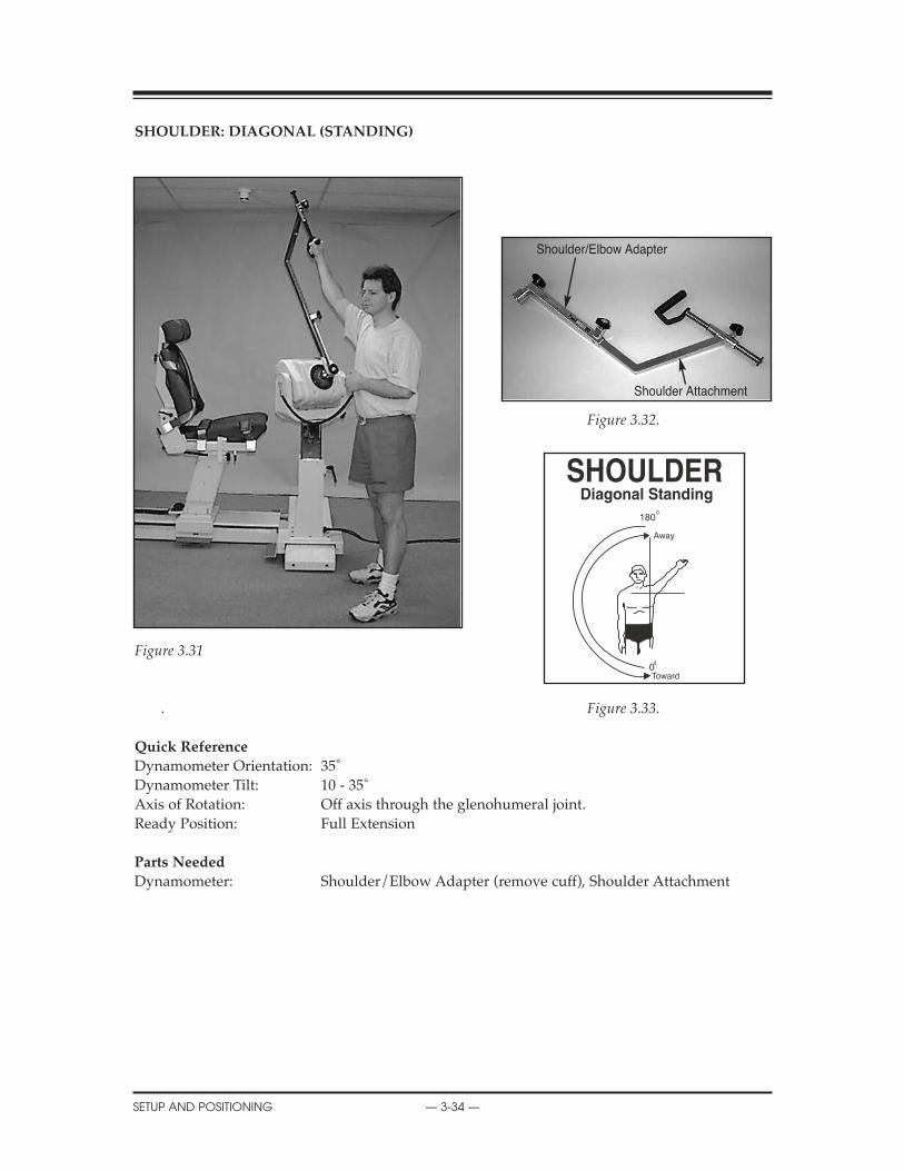
ShOULDER: DIAGONAL (STANDING)
Figure 3.32.
Figure 3.31
. Figure 3.33.
Quick Reference
Dynamometer Orientation: 35˚Dynamometer Tilt: 10 - 35˚Axis of Rotation: Off axis through the glenohumeral joint.Ready Position: Full Extension
Parts Needed
Dynamometer: Shoulder/Elbow Adapter (remove cuff), Shoulder Attachment
CONTENTS
SETUP AND POSITIONING — 3-34 —
0
180
Away
Toward
Shoulder/Elbow Adapter
Shoulder Attachment

ShOULDER: DIAGONAL (STANDING)
Setup and Positioning
(Starting Movement: Away/Flexion)
1. Attach Shoulder/Elbow Adapter to dynamometer (remove cuff). Insert Shoulder Attachmentinto Adapter.
2. Tilt dynamometer to 10 - 35 degrees. Increase or decrease the amount of horizontal abductionby varying the dynamometer height and tilt. A lower dynamometer requires more tilt, whichincreases abduction.
3. Rotate dynamometer to 35 degrees.4. Have patient stand perpendicular to dynamometer.5. Align Shaft red dot with R or L. Move attachment to an upright position. Press Hold.6. Align axis of rotation.7. Check for proper ROM. Keep handgrip loose during motion to allow for the compromising
positions of the glenoid humeral joint as it goes through the motions.8. Set ROM stops.
Opposite Side
1. Remove attachment and rotate it 180 degrees opposite. Align Shaft red dot with R or L andreattach.
2. Move attachment to an upright position. Press Hold3. Have patient face opposite way and grasp handgrip.4. Align axis of rotation (glenohumeral joint).5. Check for proper ROM. Keep handgrip loose during motion to allow for the compromising
positions of the glenohumeral joint as it goes through the motions.6. Reset ROM stops.
CONTENTS
— 3-35 — SETUP AND POSITIONING
Clinical Applications of Biodex Operating Modes
Isokinetic Mode1. Seat patient to isolate the muscular surrounding the shoulder responsible for Glenohumeral
stabilization.2. Stand patient to become more functional in the throwing pattern.3. To isolate the D2 flexors, set select ecc/con. Vary speeds accordingly.
Passive Mode1. Have patient work with the system in active assist fashion.2. Have patient light the Force Away indicator at all times to work the D2 flexors.
Isometric1. Multi-angle isometrics may be performed early in the rehabilitation process or to work near
painful points in the ROM. In this way, strength gains will be made through a portion of theunworked range.
Isotonic1. The Isotonic mode can be utilized to ensure a proper force limit is achieved.
Reactive Eccentric1. For neuromuscular re-education, vary torque limits and have patient apply the “correct” force
to ensure proper attachment movement (to challenge the patient, make various changes totorque limits without patient knowledge - but ensure that correct movement occurs.
CONTENTS
SETUP AND POSITIONING — 3-36 —
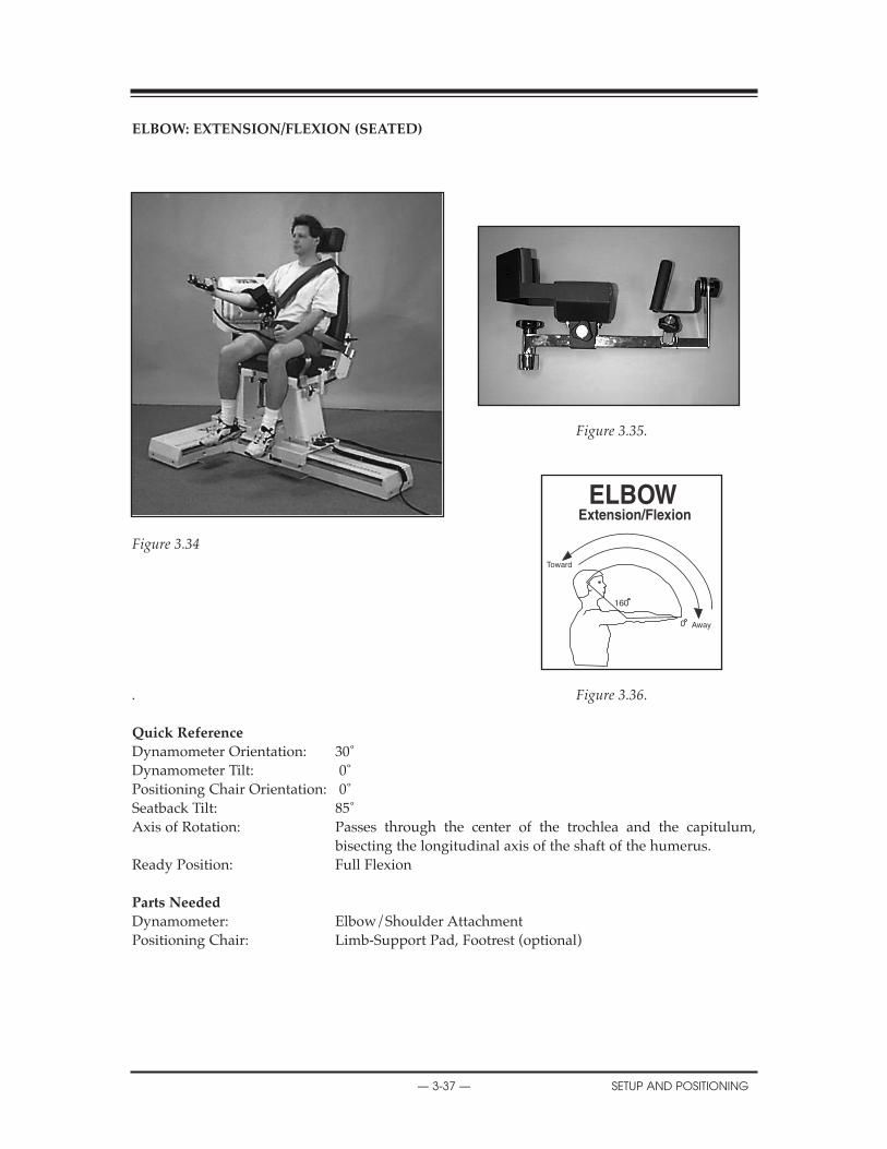
ELBOW: EXTENSION/FLEXION (SEATED)
Figure 3.35.
Figure 3.34
. Figure 3.36.
Quick Reference
Dynamometer Orientation: 30˚Dynamometer Tilt: 0˚Positioning Chair Orientation: 0˚Seatback Tilt: 85˚Axis of Rotation: Passes through the center of the trochlea and the capitulum,
bisecting the longitudinal axis of the shaft of the humerus.Ready Position: Full Flexion
Parts Needed
Dynamometer: Elbow/Shoulder AttachmentPositioning Chair: Limb-Support Pad, Footrest (optional)
CONTENTS
— 3-37 — SETUP AND POSITIONING
160
0 Away
Toward
ELBOW: EXTENSION/FLEXION
The elbow joint consists of the articulation between the trochlea of the humerus and the trochlearnotch of the ulna, the capitulum of the humerus and the facet on the head of the radius and thecircumference of the head of the radius and the radial notch of the ulna. Any bony malalignment(such as a fracture) interferes with the critical angles of these articulations making normal move-ment impossible.
Of special note at the elbow are the tendinous origins of the wrist musculature. The flexor/prona-tor muscles of the wrist originate at the medial epicondyle of the humerus and wrist extensorgroup at the lateral epicondyle. These are areas that frequently become inflamed with overuse.
Setup and Positioning
(Starting Movement: Away/Extension)
1. Seat patient on chair 2. Place Elbow/Shoulder attachment onto shaft (remove cuff). Align shaft dot with either R or
L. Bring attachment to vertical. Press Hold.3. Install limb support (angled toward patient) in chair side receiving tube for side to be tested
or exercised.4. Rest elbow on limb support. Limb support pad should be angled back with pad angled slight-
ly downward, allowing full extension. Securing strap may not be necessary.5. Rotate chair to 0 degrees.6. Rotate dynamometer to 30 degrees.7. Tilt dynamometer to 0 degrees.8. Move patient into position. Slide dynamometer along travel and raise to align axis of rotation.9. Stabilize patient with shoulder, waist and thigh straps.10. Allow handgrip to rotate as patient goes through motion. 11. Set ROM Stops.
Opposite Side
1. Press Hold.2. Unstrap patient from support pad. With patient remaining in chair, slide chair back away
from dynamometer.3. Place limb support in opposite side chair receiving tube.4. Remove attachment and rotate it 180 degrees opposite. Align shaft dot with R or L. Place
attachment back onto shaft and secure with locking knob.5. Rotate dynamometer to 30 degrees on opposite side.6. Rotate chair to 0 degrees on opposite side.7. Move patient into position. Slide dynamometer along travel to align axis of rotation. 8. Allow handgrip to rotate as patient goes through motion.9. Stabilize patient with shoulder, waist and thigh straps.10. Reset ROM stops
CONTENTS
SETUP AND POSITIONING — 3-38 —
Clinical Applications of Biodex Operating Modes
Isokinetic Mode1. The isokinetic mode may be used to work the elbow bi-directionally. In this way job specific
tasks, functional tasks, or sports activities may be simulated.
Passive Mode1. The passive mode may be used to treat inflammatory conditions of the elbow. Many times when
rest is recommended it does not mean total immobilization but the elimination of activities thatcause pain. The passive mode may be used for the effects of continuous passive motion.
2. The passive mode may be used to perform non-reciprocal contractions, e.g., working theextensors at the end range of motion both concentrically and eccentrically, as it is not uncom-mon for elbow extension to be compromised after injury or fracture.
Isometric Mode1. Isometrics may be used when pain or inflammation is a concern. Multi-angle isometrics
are recommended.
Isotonic Mode1. To simulate a functional activity, set the isotonic force accordingly to a patient task.2. Perform eccentric/concentric movements to do biceps-only exercise.
Reactive Eccentric Mode1. The eccentric mode may be used to simulate job specific tasks, e.g., the eccentric mode may
be used to work the elbow flexors, eccentrically as if the worker were lowering a heavy box.
Additional Comments1. It has been recommended by some clinicians that the dominant arm should be 5% stronger
than the non-dominant arm in recreational athletes and 10% stronger in competitive athletes.
2. Ice may be applied to the site of the lesion while the patient is in the passive mode for approx-imately fifteen minutes.
3. For cases of capsular tightness. Place the patient in the passive mode. Red range of motionlimit set buttons may be set to encompass a slightly greater range of motion than the patientcurrently is capable of moving. The percent range dials should be turned down to 55% andthe patient should be placed on the unit. Slowly and with caution, the percent ROM dialsshould be turned up. NEvER EXCEED A COMFORTABLE OR PHYSIOLOgICAL RANgE OFMOTION. ALWAYS HAvE THE COMFORT STOP AvAILABLE. The pause may also be usedfor a passive stretch at end range.
4. The elbow is frequently injured by the repeated application of stresses. Throwing injuriescommonly occur secondary to throwing too frequently and throwing repeatedly at maximumforce. These injuries may be treated by working either passively, isokinetically, or eccentrical-ly at submaximal levels.
5. Position the handgrip to concentrate on specific muscle groups. If desired, keep the handgriploose to obtain active supination or pronation.
CONTENTS
— 3-39 — SETUP AND POSITIONING

FOREARM: SUPINATION/PRONATION
Figure 3.38.
Figure 3.37. Figure 3.39.
Quick Reference
Dynamometer Orientation: 0˚Dynamometer Tilt: 5˚ (shaft down)Seat Orientation: 90˚Seatback Tilt: 85˚Elbow Flexion: 90˚Axis of Rotation: Axis of rotation for this pattern is the longitudinal line through the
center of the head of the radius proximally, and through the center of the head of the ulna distally.
Ready Position: Full Pronation
Parts Needed
Dynamometer: Wrist AttachmentPositioning Chair: Limb-Support Pad, Footrest (optional)
CONTENTS
SETUP AND POSITIONING — 3-40 —
80
0
80Away
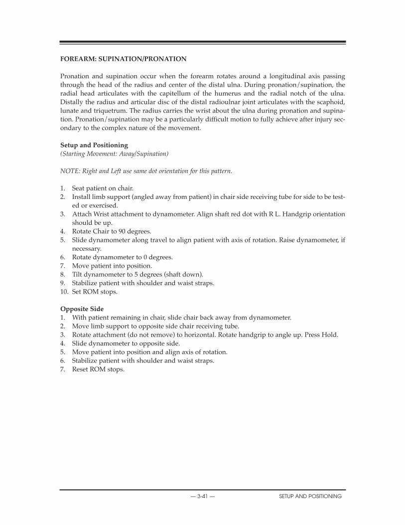
FOREARM: SUPINATION/PRONATION
Pronation and supination occur when the forearm rotates around a longitudinal axis passingthrough the head of the radius and center of the distal ulna. During pronation/supination, theradial head articulates with the capitellum of the humerus and the radial notch of the ulna.Distally the radius and articular disc of the distal radioulnar joint articulates with the scaphoid,lunate and triquetrum. The radius carries the wrist about the ulna during pronation and supina-tion. Pronation/supination may be a particularly difficult motion to fully achieve after injury sec-ondary to the complex nature of the movement.
Setup and Positioning
(Starting Movement: Away/Supination)
NOTE: Right and Left use same dot orientation for this pattern.
1. Seat patient on chair.2. Install limb support (angled away from patient) in chair side receiving tube for side to be test-
ed or exercised.3. Attach Wrist attachment to dynamometer. Align shaft red dot with R L. Handgrip orientation
should be up.4. Rotate Chair to 90 degrees.5. Slide dynamometer along travel to align patient with axis of rotation. Raise dynamometer, if
necessary. 6. Rotate dynamometer to 0 degrees.7. Move patient into position.8. Tilt dynamometer to 5 degrees (shaft down).9. Stabilize patient with shoulder and waist straps.10. Set ROM stops.
Opposite Side
1. With patient remaining in chair, slide chair back away from dynamometer. 2. Move limb support to opposite side chair receiving tube.3. Rotate attachment (do not remove) to horizontal. Rotate handgrip to angle up. Press Hold.4. Slide dynamometer to opposite side.5. Move patient into position and align axis of rotation.6. Stabilize patient with shoulder and waist straps.7. Reset ROM stops.
CONTENTS
— 3-41 — SETUP AND POSITIONING

Clinical Applications of Biodex Operating Modes:
Isokinetic Mode1. The isokinetic mode may be used at bi-directional velocities in order to simulate functional or
sports activities.
Passive Mode1. The passive mode is important for the effects of continuous passive motion. The passive mode
may be used to initiate treatment of reflex sympathetic dystrophy.
2. The passive mode may be used to work a specific muscle group both concentrically and eccen-trically, e.g., after a colles fracture, supination may be limited secondary to immobilization.The supinators may be worked both concentrically and eccentrically to gain motion andincrease strength.
Isometric Mode1. The isometric mode may be used to strengthen musculature when pain, instability or surgery
is a factor.
Isotonic Mode1. To simulate a functional activity, set the isotonic force accordingly to a patient task.
Reactive Eccentric Mode1. The eccentric mode may be used to strengthen the musculotendinous junction. This may be
important since the wrist is frequently used eccentrically during functional activities.
Additional Comments1. At certain times, full range of motion may never be achieved, e.g., if in a colles fracture the
distal radial fragment moves toward supination, there may be a permanent loss of pronation.
2. With involvement of the wrist, be careful of shoulder-hand syndrome. Be sure to mobilize theentire upper extremity.
3. If edema is a concern, the dynamometer and multi-support fixture may be raised dur-ing rehabilitation.
CONTENTS
SETUP AND POSITIONING — 3-42 —

WRIST: EXTENSION/FLEXION
Figure 3.41.
Figure 3.40.
Figure 3.42.
Quick Reference
Dynamometer Orientation: 0˚Dynamometer Tilt: 0˚Seat Orientation: 0˚Seatback Tilt: 85˚Elbow Flexion: 90˚Axis of Rotation: Axis of rotation for this pattern lies between the proximal row of the
carpals, at the capitate bone, and the radius at the radiocarpal joint.Ready Position: Full Flexion
Parts Needed
Dynamometer: Wrist AttachmentPositioning Chair: Limb-Support Pad, Footrest (optional)
CONTENTS
— 3-43 — SETUP AND POSITIONING
0
70
80
Away
Toward

WRIST: EXTENSION/FLEXION
The wrist joint consists of the distal end of the radius and the articular disc of the distal radioul-nar joint articulate with the proximal row of carpal bones (scaphoid, lunate, and triquetrum.) Thecarpal bones form a much larger surface than do the radius and the articular cartilage. This allowsfor adduction/abduction, flexion/extension and circumduction to occur. Movement also occursbetween the proximal and distal row of carpal bones. The midcarpal joint adds considerably toflexion and extension of the wrist.
Setup and Positioning
(Starting Movement: Away/Extension)
NOTE: Right and left side use same dot orientation for this pattern.
1. Seat patient on chair.2. Install limb support (angled away from patient) in chair side receiving tube.3. Attach Wrist attachment to dynamometer. Align shaft red dot with R L. Handgrip orientation
is horizontal to floor.4. Rotate dynamometer to 0 degrees.5. Rotate chair to 0 degrees.6. Set dynamometer tilt to 0 degrees.7. Move patient into position. Slide dynamometer in front of patient’s wrist to be exercised or
tested. 8. Align patient’s axis of rotation.9. Stabilize patient with shoulder and waist straps.10. Set ROM Stops.
Opposite Side
1. With patient remaining in chair, slide chair back away from dynamometer. 2. Move limb support to opposite chair side receiving tube.3. Rotate Wrist attachment to horizontal (do not remove). Press Hold.4. Rotate chair to opposite 0 degrees setting.5. Slide dynamometer to opposite side. 6. Move patient into position.7. Align axis of rotation.8. Stabilize patient with shoulder and waist straps.9. Reset ROM Stops.
CONTENTS
SETUP AND POSITIONING — 3-44 —
Clinical Applications of Biodex Operating Modes
Isokinetic Mode1. The isokinetic mode may be used bi-directionally to emphasize one particular muscle group,
e.g., in cases of golfer’s elbow where there is involvement of the flexor tendon at the elbow,the wrist flexors may be worked at low speeds and the extensors at high speeds.
Passive Mode1. The passive mode may be used for continuous passive motion effects. It may also be used to
maintain/increase range of motion, e.g., this is especially important in a colles fracture whenregaining range of motion is most difficult.
2. The passive mode may be used in cases of reflex sympathetic dystrophy which frequentlydevelops in conjunction with a colles fracture. These patients may receive sympathetic blocksfollowed by mobilization and range of motion. The patient may move passively at first and,as tolerated, begin to assist the motion in each direction.
3. The passive mode may be used to work non-reciprocally. In this way the wrist, both musclegroups or one muscle group may be exercised concentrically/eccentrically or vice versa, e.g.,in cases of tennis elbow with involvement of the common extensor tendon at the elbow, thewrist extensors may be worked concentrically/eccentrically by having the patient assist wristextension and resist wrist flexion.
Isometric Mode1. Isometrics may be used after periods of immobilization or surgery. Isometrics may be used to
strengthen musculature after very delicate surgical procedures, e.g., isometrics may be thefirst step in treating a scapholunate advanced collapse wrist.
Isotonic Mode1. To simulate a functional activity, set the isotonic force accordingly to a patient task.
Reactive Eccentric Mode1. The eccentric mode may be used to simulate functional activities. Sub-maximal eccentrics
have been used successfully to treat tendinitis.
Additional Comments1. Whenever there is wrist involvement, it is important to examine shoulder and elbow move-
ments. If there is immobility in these areas, the passive mode may be used to improve ROM.
2. Wrist flexion and extension exercises are frequently performed with the forearm pronated becausetests have demonstrated that a greater mean torque can be produced than when in supination.
3. Use of the work tools may be an important adjunct in returning a patient to work.
CONTENTS
— 3-45 — SETUP AND POSITIONING
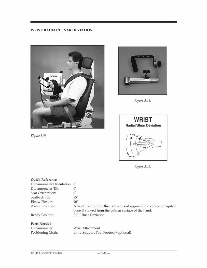
WRIST: RADIAL/ULNAR DEVIATION
Figure 3.44.
Figure 3.43.
Figure 3.45.
Quick Reference
Dynamometer Orientation: 0˚Dynamometer Tilt: 0˚Seat Orientation: 0˚Seatback Tilt: 85˚Elbow Flexion: 90˚Axis of Rotation: Axis of rotation for this pattern is at approximate center of capitate
bone if viewed from the palmar surface of the hand.Ready Position: Full Ulnar Deviation
Parts Needed
Dynamometer: Wrist AttachmentPositioning Chair: Limb-Support Pad, Footrest (optional)
CONTENTS
SETUP AND POSITIONING — 3-46 —
0
Away25
35Toward

Wrist: Radial/Ulnar
Radial/Ulnar deviation involves radiocarpal and midcarpal movement. Ulnar deviation occursover a greater ROM than radial deviation. Radial deviation is limited by bony contact of thescaphoid tubercle against the radial styloid.
Setup and Positioning
(Starting Movement: Away/Radial Deviation)
NOTE: Right and left side use same dot orientation for this pattern.
1. Seat patient on chair.2. Install limb support (angled away from patient) in chair side receiving tube.3. Attach Wrist attachment to dynamometer. Align shaft dot with R L. Handgrip orientation is up.4. Rotate dynamometer to 0 degrees.5. Rotate chair to 0 degrees.6. Set dynamometer tilt to 0 degrees.7. Move patient into position. Slide dynamometer in front of patient’s wrist to be exercised or tested.8. Slide dynamometer along travel to align axis of rotation. Raise dynamometer, if necessary.9. Stabilize patient with shoulder and waist straps.10. Set ROM Stops.
Opposite Side
1. With patient remaining in chair, slide chair back away from dynamometer. 2. Move limb support to opposite side of chair.3. Rotate Wrist attachment so handgrip faces up (do not remove). Press Hold.4. Slide dynamometer to opposite side. 5. Rotate chair to opposite 0 degrees setting.6. Set dynamometer tilt to 0 degrees.7. Move patient into position.8. Align axis of rotation.9. Stabilize patient with shoulder and waist straps.10. Reset ROM Stops.
CONTENTS
— 3-47 — SETUP AND POSITIONING

Clinical Applications of Biodex Operating Modes
Isokinetic Mode1. The isokinetic mode may be used at bi-directional velocities to simulate function or to empha-
size one particular muscle group.
Passive Mode1. The passive mode may be used post-surgically in order to gain range of motion. e.g. After
surgery to correct a scapholunate advanced collapse, place the patient in the passive mode atthe range available and gradually increase as warranted.
2. The passive mode may be used to perform concentric/concentric, concentric/eccentric, eccen-tric/concentric, and eccentric/eccentric contraction types. It is important to perform multiplecontraction types when rehabilitating the wrist since the hand performs such a wide varietyof functional tasks.
Isometric Mode1. Isometrics may be used after delicate surgical procedures or when instability is a concern. The
physician and therapist’s expertise and the type of surgery that has been performed must betaken into account when beginning any form of exercise.
Isotonic Mode1. To simulate a functional activity, set the isotonic force accordingly to a patient task.
Reactive Eccentric Mode1. The eccentric mode may be used to perform submaximal eccentrics or to simulate function-
al activities.
Additional Comments1. Swelling may be a concern when exercising the wrist and hand. If so, the multi-support fix-
ture and dynamometer may be raised to keep the hand above the level of the heart.
2. At times, there may be situations where full range of motion cannot be achieved. In a collesfracture, secondary to malalignment during healing, there may be a permanent loss in ulnardeviation. In this case, it is important to work on motions that may have been limited duringimmobilization such as ulnar deviation.
3. Whenever the wrist is involved, it is important to evaluate the entire upper extremity for lackof mobility and then treat accordingly.
SETUP AND POSITIONING — 3-48 —
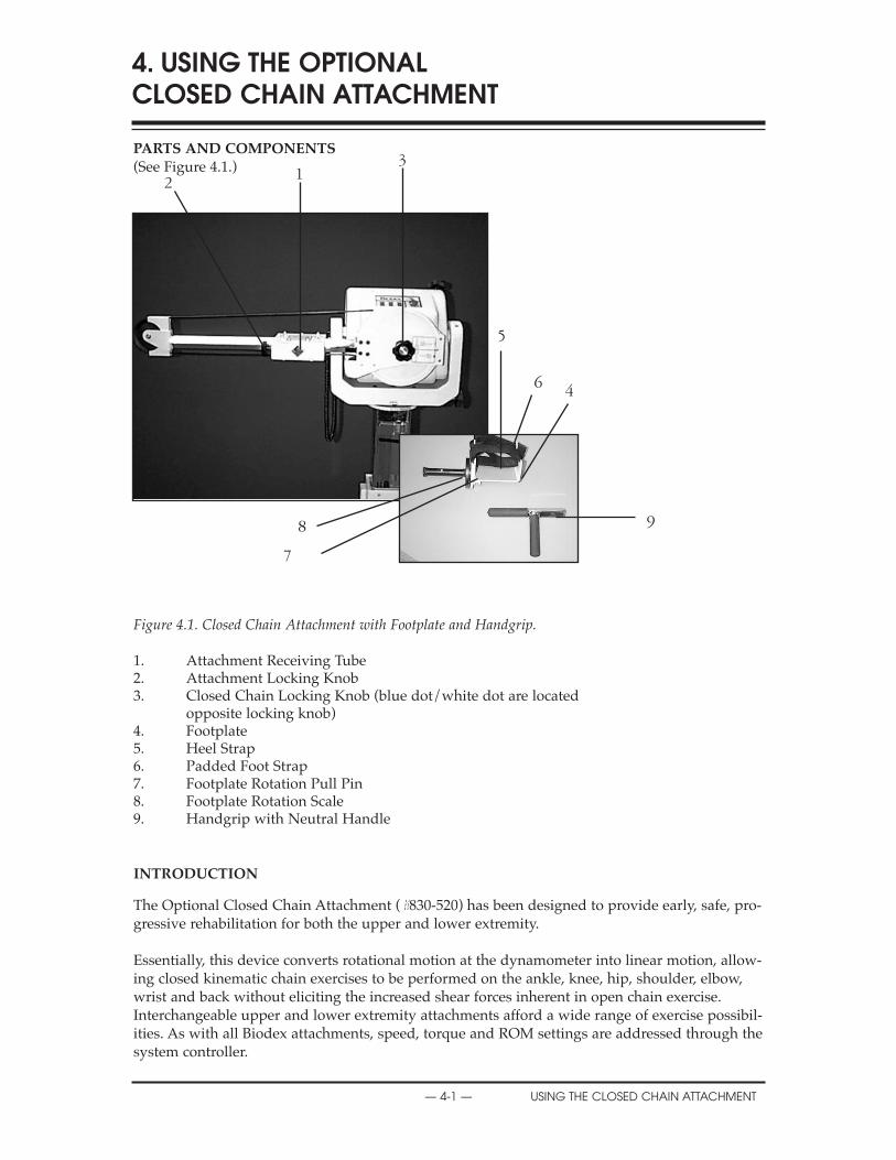
PARTS AND COMPONENTS(See Figure 4.1.)
Figure 4.1. Closed Chain Attachment with Footplate and Handgrip.
1. Attachment Receiving Tube2. Attachment Locking Knob3. Closed Chain Locking Knob (blue dot/white dot are located
opposite locking knob)4. Footplate5. Heel Strap6. Padded Foot Strap7. Footplate Rotation Pull Pin8. Footplate Rotation Scale9. Handgrip with Neutral Handle
INTRODUCTION
The Optional Closed Chain Attachment (#830-520) has been designed to provide early, safe, pro-gressive rehabilitation for both the upper and lower extremity.
Essentially, this device converts rotational motion at the dynamometer into linear motion, allow-ing closed kinematic chain exercises to be performed on the ankle, knee, hip, shoulder, elbow,wrist and back without eliciting the increased shear forces inherent in open chain exercise.Interchangeable upper and lower extremity attachments afford a wide range of exercise possibil-ities. As with all Biodex attachments, speed, torque and ROM settings are addressed through thesystem controller.
4. USING THE OPTIONAL CLOSED CHAIN ATTACHMENT
— 4-1 — USING THE CLOSED CHAIN ATTACHMENT
2 13
5
6 4
9
7
8
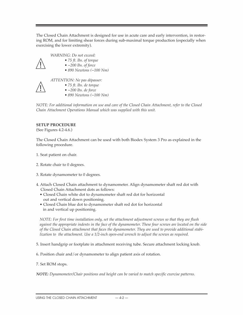
The Closed Chain Attachment is designed for use in acute care and early intervention, in restor-ing ROM, and for limiting shear forces during sub-maximal torque production (especially whenexercising the lower extremity).
WARNINg: Do not exceed:• 75 ft. lbs. of torque• ~200 lbs. of force• 890 Newtons (~100 Nm)
ATTENTION: Ne pas dépasser:• 75 ft. lbs. de torque• ~200 lbs. de force• 890 Newtons (~100 Nm)
NOTE: For additional information on use and care of the Closed Chain Attachment, refer to the ClosedChain Attachment Operations Manual which was supplied with this unit.
SETUP PROCEDURE(See Figures 4.2-4.6.)
The Closed Chain Attachment can be used with both Biodex System 3 Pro as explained in thefollowing procedure.
1. Seat patient on chair.
2. Rotate chair to 0 degrees.
3. Rotate dynamometer to 0 degrees.
4. Attach Closed Chain attachment to dynamometer. Align dynamometer shaft red dot with Closed Chain Attachment dots as follows:• Closed Chain white dot to dynamometer shaft red dot for horizontal
out and vertical down positioning.• Closed Chain blue dot to dynamometer shaft red dot for horizontal
in and vertical up positioning.
NOTE: For first time installation only, set the attachment adjustment screws so that they are flushagainst the appropriate indents in the face of the dynamometer. These four screws are located on the sideof the Closed Chain attachment that faces the dynamometer. They are used to provide additional stabi-lization to the attachment. Use a 1/2-inch open-end wrench to adjust the screws as required.
5. Insert handgrip or footplate in attachment receiving tube. Secure attachment locking knob.
6. Position chair and/or dynamometer to align patient axis of rotation.
7. Set ROM stops.
NOTE: Dynamometer/Chair positions and height can be varied to match specific exercise patterns.
CONTENTS
USING THE CLOSED CHAIN ATTACHMENT — 4-2 —
!
!
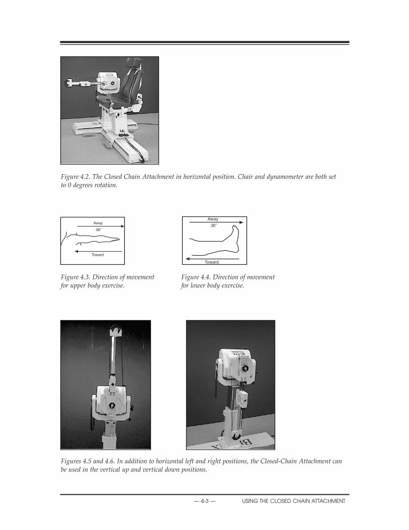
Figure 4.2. The Closed Chain Attachment in horizontal position. Chair and dynamometer are both set to 0 degrees rotation.
Figure 4.3. Direction of movement Figure 4.4. Direction of movement for upper body exercise. for lower body exercise.
Figures 4.5 and 4.6. In addition to horizontal left and right positions, the Closed-Chain Attachment canbe used in the vertical up and vertical down positions.
CONTENTS
— 4-3 — USING THE CLOSED CHAIN ATTACHMENT
36”
Away
Toward
Away
Toward
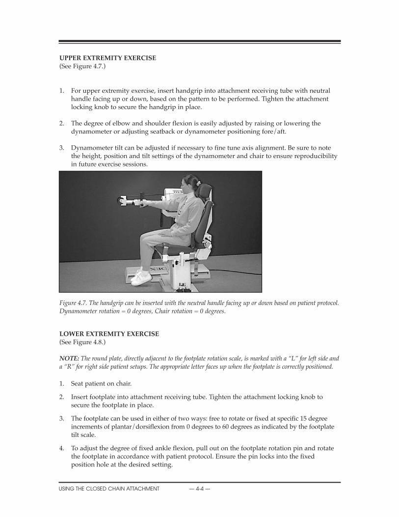
UPPER EXTREMITY EXERCISE(See Figure 4.7.)
1. For upper extremity exercise, insert handgrip into attachment receiving tube with neutral handle facing up or down, based on the pattern to be performed. Tighten the attachment locking knob to secure the handgrip in place.
2. The degree of elbow and shoulder flexion is easily adjusted by raising or lowering the dynamometer or adjusting seatback or dynamometer positioning fore/aft.
3. Dynamometer tilt can be adjusted if necessary to fine tune axis alignment. Be sure to note the height, position and tilt settings of the dynamometer and chair to ensure reproducibility in future exercise sessions.
Figure 4.7. The handgrip can be inserted with the neutral handle facing up or down based on patient protocol.Dynamometer rotation = 0 degrees, Chair rotation = 0 degrees.
LOWER EXTREMITY EXERCISE(See Figure 4.8.)
NOTE: The round plate, directly adjacent to the footplate rotation scale, is marked with a “L” for left side anda “R” for right side patient setups. The appropriate letter faces up when the footplate is correctly positioned.
1. Seat patient on chair.
2. Insert footplate into attachment receiving tube. Tighten the attachment locking knob to secure the footplate in place.
3. The footplate can be used in either of two ways: free to rotate or fixed at specific 15 degree increments of plantar/dorsiflexion from 0 degrees to 60 degrees as indicated by the footplate tilt scale.
4. To adjust the degree of fixed ankle flexion, pull out on the footplate rotation pin and rotate the footplate in accordance with patient protocol. Ensure the pin locks into the fixed position hole at the desired setting.
CONTENTS
USING THE CLOSED CHAIN ATTACHMENT — 4-4 —
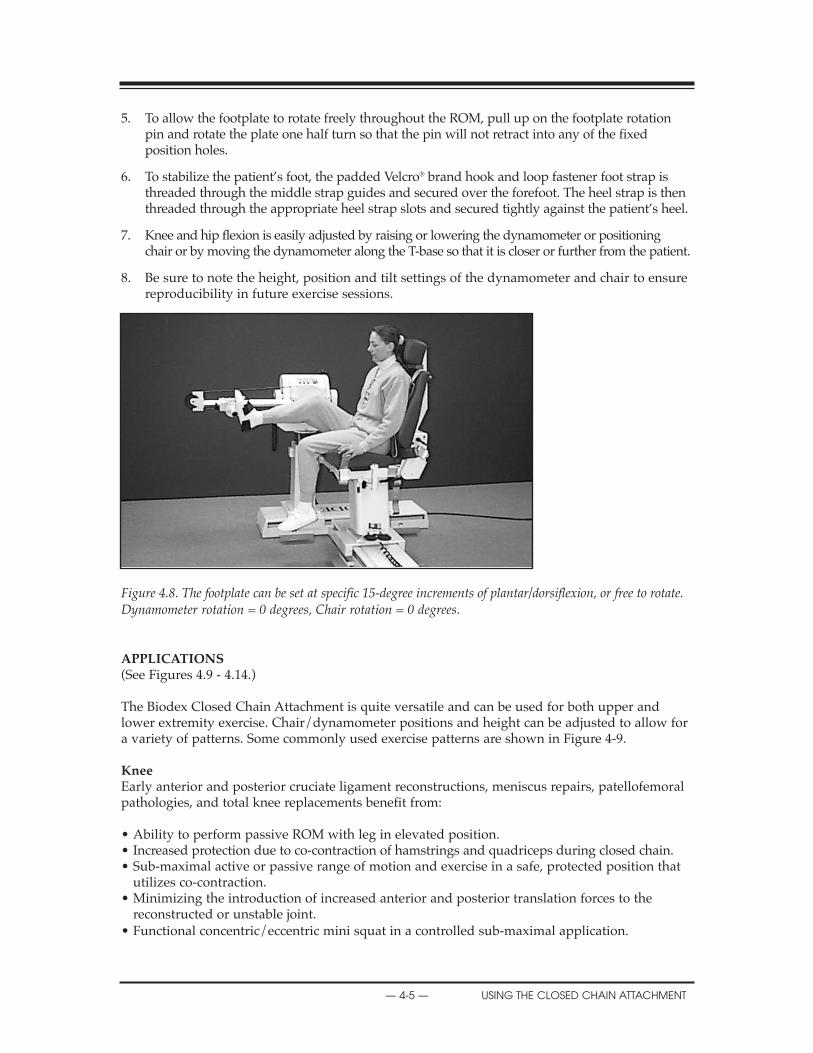
5. To allow the footplate to rotate freely throughout the ROM, pull up on the footplate rotation pin and rotate the plate one half turn so that the pin will not retract into any of the fixed position holes.
6. To stabilize the patient’s foot, the padded Velcro® brand hook and loop fastener foot strap isthreaded through the middle strap guides and secured over the forefoot. The heel strap is then threaded through the appropriate heel strap slots and secured tightly against the patient’s heel.
7. Knee and hip flexion is easily adjusted by raising or lowering the dynamometer or positioning chair or by moving the dynamometer along the T-base so that it is closer or further from the patient.
8. Be sure to note the height, position and tilt settings of the dynamometer and chair to ensure reproducibility in future exercise sessions.
Figure 4.8. The footplate can be set at specific 15-degree increments of plantar/dorsiflexion, or free to rotate.Dynamometer rotation = 0 degrees, Chair rotation = 0 degrees.
APPLICATIONS(See Figures 4.9 - 4.14.)
The Biodex Closed Chain Attachment is quite versatile and can be used for both upper andlower extremity exercise. Chair/dynamometer positions and height can be adjusted to allow fora variety of patterns. Some commonly used exercise patterns are shown in Figure 4-9.
KneeEarly anterior and posterior cruciate ligament reconstructions, meniscus repairs, patellofemoralpathologies, and total knee replacements benefit from:
• Ability to perform passive ROM with leg in elevated position.• Increased protection due to co-contraction of hamstrings and quadriceps during closed chain.• Sub-maximal active or passive range of motion and exercise in a safe, protected position that
utilizes co-contraction.• Minimizing the introduction of increased anterior and posterior translation forces to the
reconstructed or unstable joint.• Functional concentric/eccentric mini squat in a controlled sub-maximal application.
CONTENTS
— 4-5 — USING THE CLOSED CHAIN ATTACHMENT
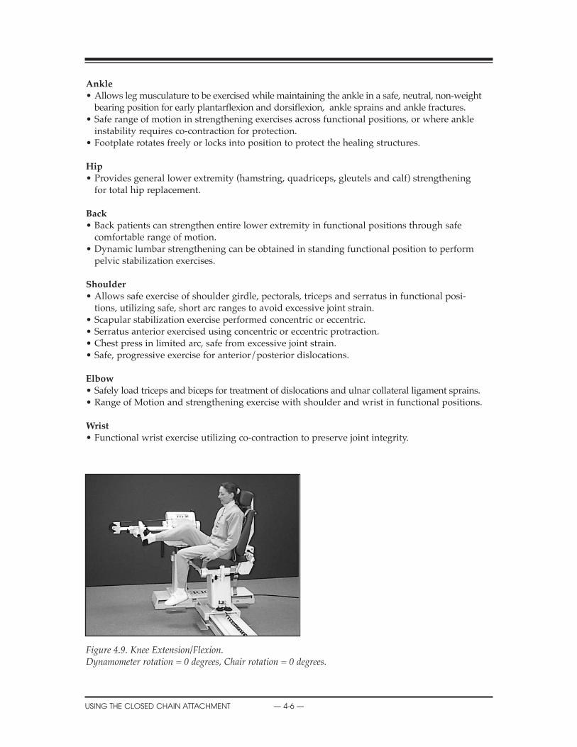
Ankle• Allows leg musculature to be exercised while maintaining the ankle in a safe, neutral, non-weight
bearing position for early plantarflexion and dorsiflexion, ankle sprains and ankle fractures.• Safe range of motion in strengthening exercises across functional positions, or where ankle
instability requires co-contraction for protection.• Footplate rotates freely or locks into position to protect the healing structures.
hip• Provides general lower extremity (hamstring, quadriceps, gleutels and calf) strengthening
for total hip replacement.
Back• Back patients can strengthen entire lower extremity in functional positions through safe
comfortable range of motion.• Dynamic lumbar strengthening can be obtained in standing functional position to perform
pelvic stabilization exercises.
Shoulder• Allows safe exercise of shoulder girdle, pectorals, triceps and serratus in functional posi-
tions, utilizing safe, short arc ranges to avoid excessive joint strain.• Scapular stabilization exercise performed concentric or eccentric.• Serratus anterior exercised using concentric or eccentric protraction.• Chest press in limited arc, safe from excessive joint strain.• Safe, progressive exercise for anterior/posterior dislocations.
Elbow• Safely load triceps and biceps for treatment of dislocations and ulnar collateral ligament sprains.• Range of Motion and strengthening exercise with shoulder and wrist in functional positions.
Wrist• Functional wrist exercise utilizing co-contraction to preserve joint integrity.
Figure 4.9. Knee Extension/Flexion.Dynamometer rotation = 0 degrees, Chair rotation = 0 degrees.
CONTENTS
USING THE CLOSED CHAIN ATTACHMENT — 4-6 —
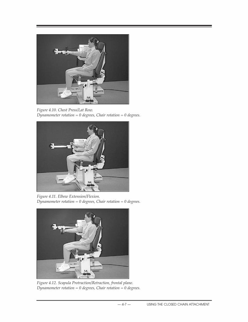
Figure 4.10. Chest Press/Lat Row.Dynamometer rotation = 0 degrees, Chair rotation = 0 degrees.
Figure 4.11. Elbow Extension/Flexion.Dynamometer rotation = 0 degrees, Chair rotation = 0 degrees.
Figure 4.12. Scapula Protraction/Retraction, frontal plane.Dynamometer rotation = 0 degrees, Chair rotation = 0 degrees.
CONTENTS
— 4-7 — USING THE CLOSED CHAIN ATTACHMENT

Figure 4.13. Scapula Protraction/Retraction, scapular plane.Dynamometer rotation = 45 degrees, Chair rotation = 15 degrees.
Figure 4.14. Overhead Elevation/DepressionDynamometer rotation = 0 degrees, Chair rotation = 15 degrees.
TEChNICAL INFORMATION
Specifications
Speed: 0-36” per second (0-90 cm/sec) @ 4500/secForce: Up to ~200 lbs. (890 Newtons)Stroke: 18” (46 cm) accommodates pediatric to 6’4” (195 cm) patientsForce Conversion: Force (lbs.) = 2.6181 x torque (ft. lbs.)Distance Conversion: Distance (in) = .08 x degrees of rotationvelocity Conversion: Vel (in/sec) = .08 x angular velocity (deg/sec)
U.S. Patent #4,907,797
CONTENTS
USING THE CLOSED CHAIN ATTACHMENT — 4-8 —

SUGGESTED TEST SPEEDS
Joint Pattern Orthopedic AthletePatient
Knee Extension/Flexion (60), 180, 300 180, 300, 450
Knee Tibial External/Internal (60), 60, 120 120, 180, 240Rotation
Shoulder Abduction/Adduction (60), 180, 300 180, 300, 450
Shoulder Flexion/Extension (60), 180, 300 180, 300, 450
Shoulder External/Internal Rotation (60), 180, 300 180, 300, 450
Shoulder D1, D2 (60), 180, 300 180, 300, 450
Shoulder Horizontal Abduction/ (60), 180, 300 180, 300, 450Adduction
Elbow Flexion/Extension (60), 180, 300 180, 300
Wrist Extension/Flexion 60, 120 120, 180
Wrist Radial/Ulnar Deviation 60, 120 120, 180
Forearm Supination/Pronation 60, 120 120, 180, 240
Ankle Plantarflexion/ 60, 120 (60), 120, 180Dorsiflexion
Ankle Eversion/Inversion 60, 120 (60), 120, 180
Hip Flexion/Extension (120), 180, 300 180, 300, 450
Hip Abduction/Adduction (120), 180, 300 180, 300, 450
Hip Internal/External Rotation 60, 120 120, 180
NOTE: Test speeds in parenthesis may be approximate depending on pathology.
5. REFERENCE MATERIALSCONTENTS
— 5-1 — REFERENCE MATERIALS
LEGAL PRECEDENT FOR BIODEX EVIDENCE
In a recent Florida court decision, the Biodex System was accepted into evidence as a measure ofdynamic human function. This decision establishes a precedent with important medical/legalimplications for all rehabilitation professionals. In the future, the testifying therapist need only citethe precedent case number for Biodex evidence to be accepted as valid.
Sue Chestnut, P.T., of Plantation Physical Therapy, testified as a witness for the plaintiff during thetrial Larry Beard vs. State Paving Co. The trial convened the week of May 21, 1986 in BrowardCounty Circuit Court, Fort Lauderdale, Florida. Case #81-12431 CH.
The plaintiff had sustained injuries in an automobile accident and was recommended to Sue’soffices in Plantation, Florida for rehabilitation. Shortly before trial, a work-up on the patient wasdone on the Biodex System. Evidence introduced indicated that the individual had a functionaldeficit on his affected side of 50%.
“Biodex evidence was integral to the case,” said Sue in a recent conversation. “The evidence wasthe only factual measure of his functional ability introduced during the trial.”
Sue was able to explain to the jury exactly how the Biodex functioned and what it was used for.This included explaining the difference between the Biodex and one of the original Isokineticdevices. The attorney for the defense was familiar with the older system, but the Biodex was newto him.
After Sue had outlined the differences to the attorney, neither the presiding judge, HonorableRobert Andrews, nor the attorney had any further question or objection. The evidence was thenlegally admitted in a United States court of law for the first time.
Evidently, the judge and attorneys were not the only ones impressed with Sue’s testimony. Thejury retired to consider its verdict and returned with a ruling in favor of Sue’s client.
BIODEX DATA ADMITTED AS MEDICAL EVIDENCE IN COURT
1. Larry Beard vs. State Paving Co.Broward County Circuit CourtFt. Lauderdale, FLDocket No. 81-12431 CHJudge: Hon. Robert Andrews
2. Gilbert Green vs. Delta AirlinesFederal CourtFt. Lauderdale, FLDocket No. 85-6656 CIVJAGAttorney: David Kratlin, Esq.
3. Grace Monico vs. G.E. Credit Corp.Broward County CourtPlantation, FLDocket No. 87-000 75CAAttorney: Jeffrey Fenster, Esq.
REFERENCE MATERIALS — 5-2 —

CONTENTS
— 5-3 — REFERENCE MATERIALS
PATIENT PROGRESS ChART
BIO
DEX

CONTENTS
REFERENCE MATERIALS — 5-4 —
JOINT MOVEMENT SPEED PEAK TORQUE/BW RANGE FLEX/EXT RATIO EXT ROT/INT ROT RATIO ABD/ADD RATIO DORSI/PLANTAR RATIO EVER/INVER RATIO
AND POSITION DEGREES/SECONDS MALE FEMALE MALE FEMALE MALE FEMALE MALE FEMALE MALE FEMALE MALE FEMALE
Lumbar Flexion 60 114 121 * *Semi Standing 90 * * * *
120 * * * *
Lumbar Extension 60 150 162 * * 49 49Semi Standing 90 133 139 * * 59 59
120 145 150 * * 51 51
Shoulder External Rot. 60 13 17 10 13Mod. Neutral 180 11 15 8 12
Shoulder Internal Rot. 60 19 26 14 18 64 71Mod. Neutral 180 17 23 13 17 66 71
Shoulder Flexion 60 25 34 23 30Seated 180 22 29 20 26
300 9 12 21 27
Shoulder Extension 60 28 37 24 31 90 79Seated 180 22 30 18 23 83 83
300 28 37 17 23 69 81
Shoulder Abduction 60 20 27 16 20Seated 180 18 24 14 18
Shoulder Adduction 60 32 43 27 35 66 64Seated 180 27 36 25 33 53 78
Ankle Plantarflexion 30 49 65 43 55Seated 60 36 48 36 46
120 23 31 20 26
Ankle Dorsiflexion 30 13 17 16 21 26 39Seated 60 11 15 15 20 31 43
120 9 12 11 14 39 54
Ankle Eversion 30 13 17 12 16Seated 60 9 12 9 12
Ankle Inversion 30 12 16 14 19 87 81Seated 60 11 14 12 15 90 80
Knee Flexion * * * * *Seated * * * * *
Knee Extension 60 86 115 80 95 61 62Seated 180 58 75 50 65 72 76
300 40 55 30 45 78 79
Hip Flexion 45 40 52 38 50Supine 300 10 13 7 9
Hip Extension 45 63 82 57 77 64 66Supine 300 34 44 28 37 29 25
Elbow Flexion 60 21 28 20 26Seated 120 21 28 34 45
Elbow Extension 60 21 28 23 30 97 88Seated 120 23 30 18 24 93 98
Wrist Flexion 60 4 7 4 7Seated 120 2 4 2 4
Wrist Extension 60 2 4 2 4 57 57Seated 120 2 4 2 4 97 97
CURRENT RECORDED NORMATIVE GOALS (ENGLISh UNITS)
* The Biodex normative database is a compilation of published information to be used as unilateral goals.Peak Torque to body weight is expressed in a range which enables these goals to be recommended for vari-ous groups (Prepubescent patients do not apply)

CONTENTS
— 5-5 — REFERENCE MATERIALS
JOINT MOVEMENT SPEED PEAK TORQUE/BW RANGE FLEX/EXT RATIO EXT ROT/INT ROT RATIO ABD/ADD RATIO DORSI/PLANTAR RATIO EVER/INVER RATIO
AND POSITION DEGREES/SECONDS MALE FEMALE MALE FEMALE MALE FEMALE MALE FEMALE MALE FEMALE MALE FEMALE
Lumbar Flexion 60 38.1 40.4 * *Semi Standing 90 * * * *
120 * * * *
Lumbar Extension 60 50.1 54.1 * * 49 49Semi Standing 90 44.4 46.4 * * 59 59
120 48.4 50.1 * * 51 51
Shoulder External Rot. 60 4.3 5.7 3.3 4.3Mod. Neutral 180 3.7 5.0 2.7 4.0
Shoulder Internal Rot. 60 6.3 8.7 4.7 6.0 64 71Mod. Neutral 180 5.7 7.7 4.3 5.7 66 71
Shoulder Flexion 60 8.4 11.4 7.7 10.0Seated 180 7.4 9.7 6.7 8.7
300 3.0 4.0 7.0 9.0
Shoulder Extension 60 9.4 12.4 8.0 10.4 90 79Seated 180 7.3 10.0 6.0 7.7 83 83
300 9.4 12.4 5.7 7.7 69 81
Shoulder Abduction 60 6.7 9.0 5.3 6.7Seated 180 6.0 8.0 4.7 6.0
Shoulder Adduction 60 10.7 14.3 9.0 11.7 66 64Seated 180 9.0 12.0 8.4 11.0 53 78
Ankle Plantarflexion 30 16.4 21.7 14.4 18.4Seated 60 12.0 16.0 12.0 15.4
120 7.7 10.4 6.7 8.7
Ankle Dorsiflexion 30 4.3 5.7 5.3 7.0 26 39Seated 60 3.7 5.0 5.0 6.7 31 43
120 3.0 4.0 3.7 4.7 39 54
Ankle Eversion 30 4.3 5.7 4.0 5.3Seated 60 3.0 4.0 3.0 4.0
Ankle Inversion 30 4.0 5.3 4.7 6.3 87 81Seated 60 3.7 4.7 4.0 5.0 90 80
Knee Flexion * * * * *Seated * * * * *
Knee Extension 60 28.7 38.4 2.7 31.7 61 62Seated 180 19.4 25.1 16.7 21.7 72 76
300 13.4 18.4 10.0 15.0 78 79
Hip Flexion 45 13.4 17.4 12.7 16.7Supine 300 3.3 4.3 2.3 3.0
Hip Extension 45 21.0 27.4 19.0 25.7 64 66Supine 300 11.4 14.7 9.4 12.4 29 25
Elbow Flexion 60 7.0 9.4 6.7 8.7Seated 120 7.0 9.4 11.4 15.0
Elbow Extension 60 7.0 9.4 7.7 10.0 97 88Seated 120 7.7 10.0 6.0 8.0 93 98
Wrist Flexion 60 1.3 2.3 1.3 2.3Seated 120 .7 1.3 .7 1.3
Wrist Extension 60 .7 1.3 .7 1.3 57 57Seated 120 .7 1.3 .7 1.3 97 97
CURRENT RECORDED NORMATIVE GOALS- (METRIC UNITS)

EMG/ANALOG SIGNAL ACCESS INTERFACE*
The EMG/Analog Signal Access Configuration Utility (ASA Config) is part of the EMG/AnalogSignal Access Interface option to the System 3, Rev 2. The utility configures the scale factors andoperating modes of the analog signal outputs for velocity, torque and position.
With the configuration capability, the analog signals can be custom tailored to provide the bestand most appropriate analog data for a wide variety of usages.
Installation and UsageThe ASA Config utility must be installed on the System 3 computer, which runs the System 3application software. Insert the provided ASA Config utility CD into the CD drive, and it willautomatically start the setup installation. If all the defaults are chosen during setup, a shortcut willbe created on your desktop called: System 3 ASA Config.
The utility cannot be run simultaneously with the System 3 application. Typically you must exitthe System 3 application, run the ASA Config utility to setup the scaling and modes, then run theSystem 3 application to perform your tests and data capture.
All settings performed in the ASA Config utility will be permanently set in the System 3, even ifthe unit is completely shut down and re-started. The current settings can always be verified byrunning the utility – it will show the current active settings. Status information on the System 3 isshown on the top of the screen for your reference. As long as the status shows ONLINE, the cur-rent displayed Analog Signal settings are accurate.
The Analog Signal Access port is an output of analog signals of velocity, torque and position datain real-time directly from the motor control Digital Signal Processor (DSP). In addition to the real-time data, a synchronization pulse is issued whenever the real-time data is updated. The syn-chronization pulse can be used by the monitoring equipment to know when the real-time dataoutput has changed.
Note: For the pin-out definition of the port, please refer to the diagram at the back of this docu-ment entitled: EMG/Analog Signal Port Pin Configuration
Analog Signal Resolution Effected By Scale FactorThe analog signals range from –5 volts to +5 volts, resulting in a total range of 10 volts. The Systemdefaults to full scale. Full scale for torque as an example is –512 ft-lbs to +512 ft-lbs, for a totalrange of 1024 ft-lbs. This results in an output resolution scale factor as follows:
1024 ft-lbs = 10 volts,
1 ft-lb = 9.8 milli-volts
*Consult with Biodex Customer Service before ordering.
6. APPENDICESENTS
APPENDICES — 6-1 —
9.8 milli-volts is well below the signal noise rated for this port, therefore it’s not possible to see 1ft-lb increments on this analog signal. This program provides scaling options separately for allthree analog signals, so if typical usage is well below the maximum levels, 1 ft-lb increments canbe seen on typical analog monitoring equipment. For example, applying a range of +/- 0 to 64 ft-lbs, the output resolution scale factor would look as follows:
128 ft-lbs = 10 volts,
1 ft-lb = 78.1 milli-volts
78.1 milli-volts is well above the worse case of signal noise (15 – 35 mV), so increments as low as1/4 to 1/2 ft-lbs can be seen reliably. The original System 3 design had only a 0 to 5 volts range onthe analog signals (ie: 1/2 the resolution of System 3 Rev 2), therefore this example has 16 timesthe resolution of the original System 3!
Operating ModesThe Output Frequency, or update rate, controls how frequent System 3 will change the analog out-puts. The best it can do is 2,000 times per second, which is the default. If this high frequency is notneeded or may even be causing problems with the monitoring equipment, the update rate can belowered. Every time the analog signals are output, the synchronization signal is pulsed also.Therefore the update rate controls how frequent the synchronization signal (i.e.: “syncout”) is pulsed.
NOTE: Syncout is a Digital TTL pulse which is Active High and has a continuous pulse width of 29micro-seconds.
The Output Mode selects in what state the analog signal outputs are updated. The options areas follows:
On Always - always output regardless of current operational state
On Timed - turns on analog outputs only for the next fixed period of time (in seconds)
Off (disabled) - totally shuts down the analog signal outputs
Auto, when active - is automatically on only when the system is in an active state, meaning notSTOP’ed and not in HOLD
On Go command - synchronizes the analog signal output with the System 3 application’s GO com-mand, so the output is performed only during the trials exercised
NOTE: Use the <Refresh> button to display the current Remote Access Port setting in effect.
CONTENTS
— 6-2 — APPENDICES
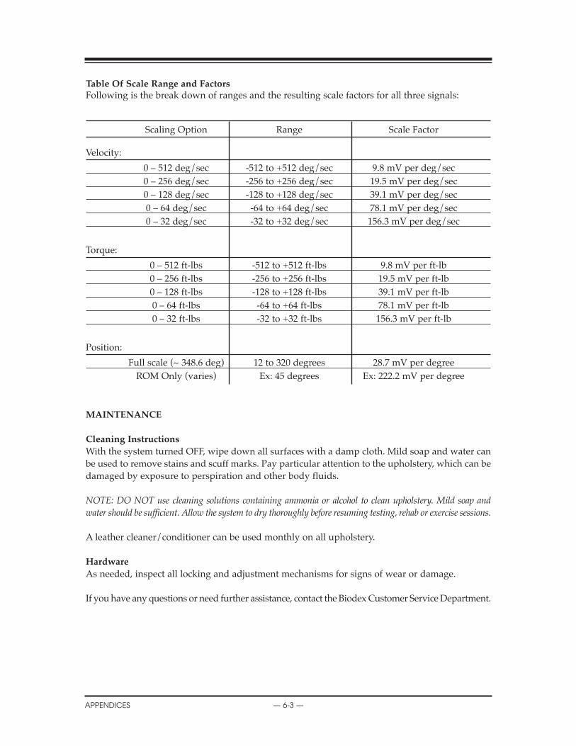
Table Of Scale Range and FactorsFollowing is the break down of ranges and the resulting scale factors for all three signals:
Scaling Option Range Scale Factor
Velocity:
0 – 512 deg/sec -512 to +512 deg/sec 9.8 mV per deg/sec0 – 256 deg/sec -256 to +256 deg/sec 19.5 mV per deg/sec0 – 128 deg/sec -128 to +128 deg/sec 39.1 mV per deg/sec0 – 64 deg/sec -64 to +64 deg/sec 78.1 mV per deg/sec0 – 32 deg/sec -32 to +32 deg/sec 156.3 mV per deg/sec
Torque:
0 – 512 ft-lbs -512 to +512 ft-lbs 9.8 mV per ft-lb0 – 256 ft-lbs -256 to +256 ft-lbs 19.5 mV per ft-lb0 – 128 ft-lbs -128 to +128 ft-lbs 39.1 mV per ft-lb0 – 64 ft-lbs -64 to +64 ft-lbs 78.1 mV per ft-lb0 – 32 ft-lbs -32 to +32 ft-lbs 156.3 mV per ft-lb
Position:
Full scale (~ 348.6 deg) 12 to 320 degrees 28.7 mV per degreeROM Only (varies) Ex: 45 degrees Ex: 222.2 mV per degree
MAINTENANCE
Cleaning Instructions
With the system turned OFF, wipe down all surfaces with a damp cloth. Mild soap and water canbe used to remove stains and scuff marks. Pay particular attention to the upholstery, which can bedamaged by exposure to perspiration and other body fluids.
NOTE: DO NOT use cleaning solutions containing ammonia or alcohol to clean upholstery. Mild soap andwater should be sufficient. Allow the system to dry thoroughly before resuming testing, rehab or exercise sessions.
A leather cleaner/conditioner can be used monthly on all upholstery.
hardware
As needed, inspect all locking and adjustment mechanisms for signs of wear or damage.
If you have any questions or need further assistance, contact the Biodex Customer Service Department.
CONTENTS
APPENDICES — 6-3 —

SYSTEM SPECIFICATIONS
Electrical Requirements
Clinical Data Station and Controller Cart: 208/230VAC, 50-60Hz, 8 amps Requires 20A isolated dedicated service
Hospital Grade Plug must be rated for 230VAC, 15 amps minimumNorth American Units supplied with NEMA 6-20P
North American Chair Lift: 115VAC 60Hz, 4 ampsHospital Grade Plug NEMA 5-15P, must be rated for 115V, 15 amps minimum
European Chair Lift: 230VAC 50-60Hz, 2 ampsHospital Grade Plug must be rated for 230VAC, 15 amps minimum
Equipment should have means to isolate its circuits electrically from the supply mains on allpoles, simultaneously.
Mechanical Specifications
Total Weight (Pro Configuration): 1350 pounds
Physical Dimensions:CDS Cart: 27 inches wide, 24 inches deep, 66 inches highT-Base & Chair: 52 inches wide, 65 inches deep, 60 inches highAttachment Cart: 50 inches wide, 26 inches deep, 50 inches high
Compliance
Class 1 Ordinary equipment
ETL listed in compliance with: UL2601-1 & CAN/CSA C22.2 No. 601.1.EN 60601-1-1CE marked for EMC (ElecroMagnetic Compatibility) per EN60601-1-2 includes: EN55011, IEC 801-2,IEC 801-3, IEC 801-4, IEC 801-5
Authorized European Community Representative: Prothia, Paris, France
CONTENTS
— 6-4 — APPENDICES
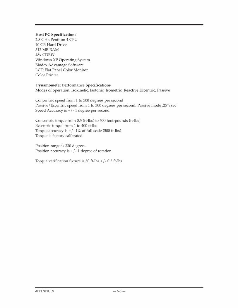
host PC Specifications
2.8 GHz Pentium 4 CPU40 GB Hard Drive 512 MB RAM48x CDRWWindows XP Operating SystemBiodex Advantage SoftwareLCD Flat Panel Color MonitorColor Printer
Dynamometer Performance Specifications
Modes of operation: Isokinetic, Isotonic, Isometric, Reactive Eccentric, Passive
Concentric speed from 1 to 500 degrees per secondPassive/Eccentric speed from 1 to 300 degrees per second, Passive mode .25°/secSpeed Accuracy is +/- 1 degree per second
Concentric torque from 0.5 (ft-lbs) to 500 foot-pounds (ft-lbs)Eccentric torque from 1 to 400 ft-lbsTorque accuracy is +/- 1% of full scale (500 ft-lbs)Torque is factory calibrated
Position range is 330 degreesPosition accuracy is +/- 1 degree of rotation
Torque verification fixture is 50 ft-lbs +/- 0.5 ft-lbs
CONTENTS
APPENDICES — 6-5 —

GENERAL PRODUCT WARRANTY
A. Warranty
BIODEX MEDICAL SYSTEMS warrants that all products covered hereby shall be free from defectsin workmanship and materials and shall conform to published specifications or other specifica-tions accepted in writing by BIODEX for:
Description: Parts: Labor:Controller 1 year 1 yearDynamometer 1 year 1 yearClinical DataStation 1 year 1 yearPrinter 1 year 1 yearCables 1 year 1 yearAdjust. Positioning Chair 1 year 1 yearAttachments 1 year 1 yearThreads 1 year 1 yearKnobs 1 year 1 yearUpholstery 60 days 60 daysStraps 60 days 60 daysPads 60 days 60 days
under normal use as prescribed in the operator’s manual. The foregoing warranty does not applyto any products which have been subject to use other than as specified as standard operating pro-cedure in the system manual, neglect, accident or modification. BIODEX’s sole obligation to buyerhereunder for products failing to meet aforesaid warranty shall be, at BIODEX’s discretion, toreplace or repair the non-conforming product (parts and labor) or issue buyer credit for the pur-chase price of the non-conforming product where within warranty period:
1. BIODEX has received written notice of any nonconformity and
2. After BIODEX’s attempts to remedy such nonconformity, BIODEX has determined that the nonconformity is not a result of improper use, accident, repair or other misuse by buyer.
Any replacement product shall carry the unexpired term of the warranty which was applicable tothe replaced product or a period of 30 days, whichever is longest.
BIODEX MAY RETAIN THE RIGHT TO VOID ALL SYSTEM WARRANTIES IF PAYMENT ISNOT RECEIVED AS PRESCRIBED IN TERMS OF PURCHASE.
EXCEPT AS SPECIFICALLY PROVIDED HEREIN, THERE ARE NO OTHER WARRANTIES,EXPRESS OR IMPLIED, INCLUDING, BUT NOT LIMITED TO, ANY IMPLIED WARRANTIESOF MERCHANTABILITY OR FITNESS FOR A PARTICULAR PURPOSE.
IN NO EVENT SHALL BIODEX BE LIABLE FOR LOSS OF PROFITS, INDIRECT, SPECIAL, CON-SEQUENTIAL, OR OTHER SIMILAR DAMAGES ARISING OUT OF ANY BREACH HEREOF.
CONTENTS
— 6-6 — APPENDICES

B. Warranty Period
Warranty time period stated in paragraph “A”, is from date of invoice (shipment) unless other-wise specified in writing by BIODEX.
C. Repaired or Replacement Products (out of warranty)
BIODEX MEDICAL SYSTEMS, for a period of 60 days, warrants that its standard productsrepaired or replaced hereunder shall be free from defects in workmanship or materials under nor-mal use as described in the system’s Operator’s Manual. Warranty period will begin upon ship-ment of repaired or replacement products. The sole responsibility of BIODEX under this warran-ty is, at its option, to repair or replace any defective component parts of such products. This war-ranty does not apply to:
1. Products which have been repaired or altered other than under specific instructions from BIODEX’S Service Department instruction as listed in system’s manuals or procedures previously approved in writing by BIODEX Service Department,or
2. Products which have been subject to use other than described as standard use in the system’soperator’s manual, neglect or accident.
THIS WARRANTY IS NOT TRANSFERABLE (SITE, OWNERSHIP, ETC.) WITHOUT THE WRIT-TEN PERMISSION OF BIODEX MEDICAL SYSTEMS. WARRANTY IS VOID UNLESS EQUIP-MENT IS INSTALLED BY BIODEX PERSONNEL.
CONTENTS
APPENDICES — 6-7 —

BIODEXBiodex Medical Systems, Inc.
20 Ramsay Road, Shirley, New York, 11967-4704, Tel: 800-224-6339 (In NY and Int’l, call 631-924-9000), Fax: 631-924-9338, Email: [email protected], www.biodex.com