system description sma flexible storage …files.sma.de/dl/30486/si44m-80h-12-fss-ia-en-10.pdfsystem...
TRANSCRIPT
System descriptionSMA FLEXIBLE STORAGE SYSTEMIncreased self-consumption with SUNNY ISLAND 4.4M / 6.0H / 8.0H andSUNNY HOME MANAGER
SI44M-80H-12-FSS-IA-en-10 | Version 1.0ENGLISH

Legal ProvisionsThe information contained in these documents is property of SMA Solar Technology AG. Any publication, whether inwhole or in part, requires prior written approval by SMA Solar Technology AG. Internal reproduction used solely forthe purpose of product evaluation or other proper use is allowed and does not require prior approval.
SMA WarrantyYou can download the current warranty conditions from the Internet at www.SMA-Solar.com.
TrademarksAll trademarks are recognized, even if not explicitly identified as such. Missing designations do not mean that aproduct or brand is not a registered trademark.Modbus® is a registered trademark of Schneider Electric and is licensed by the Modbus Organization, Inc.QR Code is a registered trademark of DENSO WAVE INCORPORATED.Phillips® and Pozidriv® are registered trademarks of Phillips Screw Company.Torx® is a registered trademark of Acument Global Technologies, Inc.
SMA Solar Technology AGSonnenallee 134266 NiestetalGermanyTel. +49 561 9522-0Fax +49 561 9522-100www.SMA.deEmail: [email protected]
Status: 9/12/2017Copyright © 2017 SMA Solar Technology AG. All rights reserved.
Legal Provisions SMA Solar Technology AG
System descriptionSI44M-80H-12-FSS-IA-en-102

Table of Contents1 Information on this Document..................................................................................................... 4
1.1 Validity ............................................................................................................................................................. 41.2 Content and Structure of this Document......................................................................................................... 41.3 Target Group ................................................................................................................................................... 41.4 Additional Information..................................................................................................................................... 41.5 Symbols............................................................................................................................................................ 41.6 Typographies ................................................................................................................................................... 51.7 Nomenclature .................................................................................................................................................. 5
2 Safety ............................................................................................................................................ 62.1 Intended Use.................................................................................................................................................... 62.2 Safety Information ........................................................................................................................................... 62.3 Battery Safety Information............................................................................................................................... 9
3 Functions and Design................................................................................................................... 113.1 Functions of the SMA Flexible Storage System ............................................................................................. 113.2 Requirements of VDE Application Guide 2510-2 ......................................................................................... 113.3 Requirements for Communication................................................................................................................... 12
4 System with One Sunny Island ................................................................................................... 134.1 Circuitry Overview for a System with One Sunny Island Inverter ................................................................ 134.2 Connection of the Sunny Island...................................................................................................................... 14
5 System With Three Sunny Island Inverters ................................................................................ 165.1 Circuitry Overview for a System with Three Sunny Island Inverters ............................................................. 165.2 Connecting the Master.................................................................................................................................... 175.3 Connecting the Slaves..................................................................................................................................... 18
6 Commissioning ............................................................................................................................. 206.1 Commissioning Procedure............................................................................................................................... 206.2 Adjusting the Configuration of the Sunny Island ........................................................................................... 206.3 Commissioning a System With Increased Self-Consumption........................................................................ 22
7 Contact .......................................................................................................................................... 24
Table of ContentsSMA Solar Technology AG
System description 3SI44M-80H-12-FSS-IA-en-10
1 Information on this Document
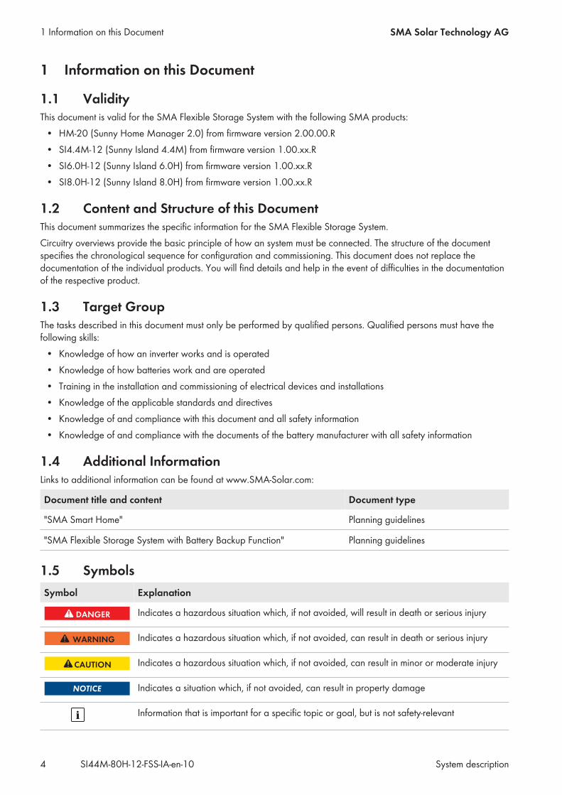
1.1 ValidityThis document is valid for the SMA Flexible Storage System with the following SMA products:
• HM-20 (Sunny Home Manager 2.0) from firmware version 2.00.00.R• SI4.4M-12 (Sunny Island 4.4M) from firmware version 1.00.xx.R• SI6.0H-12 (Sunny Island 6.0H) from firmware version 1.00.xx.R• SI8.0H-12 (Sunny Island 8.0H) from firmware version 1.00.xx.R
1.2 Content and Structure of this DocumentThis document summarizes the specific information for the SMA Flexible Storage System.Circuitry overviews provide the basic principle of how an system must be connected. The structure of the documentspecifies the chronological sequence for configuration and commissioning. This document does not replace thedocumentation of the individual products. You will find details and help in the event of difficulties in the documentationof the respective product.
1.3 Target GroupThe tasks described in this document must only be performed by qualified persons. Qualified persons must have thefollowing skills:
• Knowledge of how an inverter works and is operated• Knowledge of how batteries work and are operated• Training in the installation and commissioning of electrical devices and installations• Knowledge of the applicable standards and directives• Knowledge of and compliance with this document and all safety information• Knowledge of and compliance with the documents of the battery manufacturer with all safety information
1.4 Additional InformationLinks to additional information can be found at www.SMA-Solar.com:
Document title and content Document type
"SMA Smart Home" Planning guidelines
"SMA Flexible Storage System with Battery Backup Function" Planning guidelines
1.5 SymbolsSymbol Explanation
Indicates a hazardous situation which, if not avoided, will result in death or serious injury
Indicates a hazardous situation which, if not avoided, can result in death or serious injury
Indicates a hazardous situation which, if not avoided, can result in minor or moderate injury
Indicates a situation which, if not avoided, can result in property damage
Information that is important for a specific topic or goal, but is not safety-relevant
1 Information on this Document SMA Solar Technology AG
System descriptionSI44M-80H-12-FSS-IA-en-104

Symbol Explanation
Indicates a requirement for meeting a specific goal
Desired result
A problem that might occur
1.6 TypographiesTypography Use Example
bold • Terminals• Slots• Parameters• Elements on the user interface• Elements to be selected• Elements to be entered
• The value can be found in the fieldEnergy.
• Select Settings.• Enter 10 in the field Minutes.
> • Connects several elements to beselected
• Select Settings > Date.
[Button] • Button to be selected or pressed • Select [Next].
1.7 NomenclatureComplete designation Designation in this document
SMA Flexible Storage System Battery storage system
Sunny Boy, Sunny Mini Central, Sunny Tripower PV inverter
Sunny Places, Sunny Portal, Sunny Home Manager Communication product
SMA Speedwire Speedwire
1 Information on this DocumentSMA Solar Technology AG
System description 5SI44M-80H-12-FSS-IA-en-10

2 Safety
2.1 Intended UseThe SMA Flexible Storage System is a battery storage system and optimizes self-consumption of PV energy by thefollowing measures:
• Intermediate storage of excess PV energy with the Sunny Island• Visualization of PV system data in Sunny Portal
The SMA Flexible Storage System does not form a battery-backup grid in the event of utility grid failure (for installationof a battery-backup system, see the system description "SMA FLEXIBLE STORAGE SYSTEM with Battery-BackupFunction" at www.SMA-Solar.com).The SMA Flexible Storage System must only be used in those countries for which it is licensed or in those countries forwhich it is approved by SMA Solar Technology AG and the grid operator. The grid configuration of the utility gridmust be a TN or TT system.Grid feed-in and purchased electricity are recorded with an SMA Energy Meter only. An SMA Energy Meter does notreplace the energy meter of the electric utility company.The entire battery voltage range must be completely within the permissible DC input voltage range of the Sunny Island.The maximum permissible DC input voltage of the Sunny Island must not be exceeded. A battery fuse must be installedbetween the battery and the Sunny Island.With lead-acid batteries, the battery room must be ventilated in accordance with the requirements of the batterymanufacturer and with the locally applicable standards and directives (see documentation of the batterymanufacturer).The following conditions must be satisfied for lithium-ion batteries:
• The lithium-ion battery must comply with the locally applicable standards and directives and must be intrinsicallysafe.
• The battery management of the lithium-ion battery used must be compatible with the Sunny Island (see thetechnical information at “List of Approved Batteries”).
An DC supply grid may not be established with the Sunny Island.DC charge controller must not be connected in the battery storage system.Loads connected to the Sunny Island must have an CE, RCM or UL identification label.Single-phase clusters are not permitted. Only Sunny Island inverters of the same device type may be installed in athree-phase cluster. Several clusters may only be interconnected if the Multicluster-Box 12 (MC-BOX-12.3-20) is usedfor it.The SMA Flexible Storage System can be installed at altitudes of up to 2000 m above MSL.Use this product only in accordance with the information provided in the enclosed documentation and with the locallyapplicable standards and directives. Any other application may cause personal injury or property damage.Alterations to the product, e.g. changes or modifications, are only permitted with the express written permission ofSMA Solar Technology AG. Unauthorized alterations will void guarantee and warranty claims and in most casesterminate the operating license. SMA Solar Technology AG shall not be held liable for any damage caused by suchchanges.Any use of the product other than that described in the Intended Use section does not qualify as the intended use.The enclosed documentation is an integral part of this product. Keep the documentation in a convenient place forfuture reference and observe all instructions contained therein.
2.2 Safety InformationThis section contains safety information that must be observed at all times when working on or with the product.
2 Safety SMA Solar Technology AG
System descriptionSI44M-80H-12-FSS-IA-en-106

To prevent personal injury and property damage and to ensure long-term operation of the product, read this sectioncarefully and observe all safety information at all times.
Danger to life from electric shock due to live voltageHigh voltages are present in the live components of the inverter when in operation. Touching live components resultsin death or serious injury due to electric shock.
• Wear suitable personal protective equipment for all work on the product.• Do not touch any live components.• Observe all warning messages on the inverter and in the documentation.• Observe all safety information of the battery manufacturer.• Switch off or disconnect the following components from voltage sources in the following order before carrying
out any work:– Sunny Island– The circuit breakers of the Sunny Island, the control and measurement voltages– All circuit breakers and load-break switches of the connected AC sources– Load-break switch of the battery fuse
• Ensure that no disconnected devices can be reconnected.• After disconnecting the Sunny Island from voltage sources, wait at least 15 minutes for the capacitors to
discharge completely before opening the doors.• Before carrying out any work make sure that all devices are completely voltage-free.• Cover or isolate any adjacent live components.
Danger to life due to electric shockOvervoltages (e. g. in the case of a flash of lightning) can be further conducted into the building and to otherconnected devices in the same network via network cables or other data cables if there is no overvoltage protection.
• Ensure that all devices in the same network and the battery are integrated in the existing overvoltage protection.• When laying the network cables or other data cables outdoors, attention must be given to suitable overvoltage
protection at the cable transition from the inverter or the battery outdoors to the inside of a building.
Danger to life from electric shock due to overvoltagesOvervoltages of up to 1500 V can occur in the stand-alone grid and in the battery-backup grid. If the connectedloads have not been designed for these overvoltages, a voltage that poses a danger to life may be present onaccessible parts for several seconds.
• Only connect loads that have a CE, RCM or UL designation. Loads with a CE, RCM or UL designation aredesigned for overvoltages of up to 1500 V.
• Operate the loads only when they are technically faultless and in an operationally safe state.• Check the loads regularly for visible damage.
2 SafetySMA Solar Technology AG
System description 7SI44M-80H-12-FSS-IA-en-10
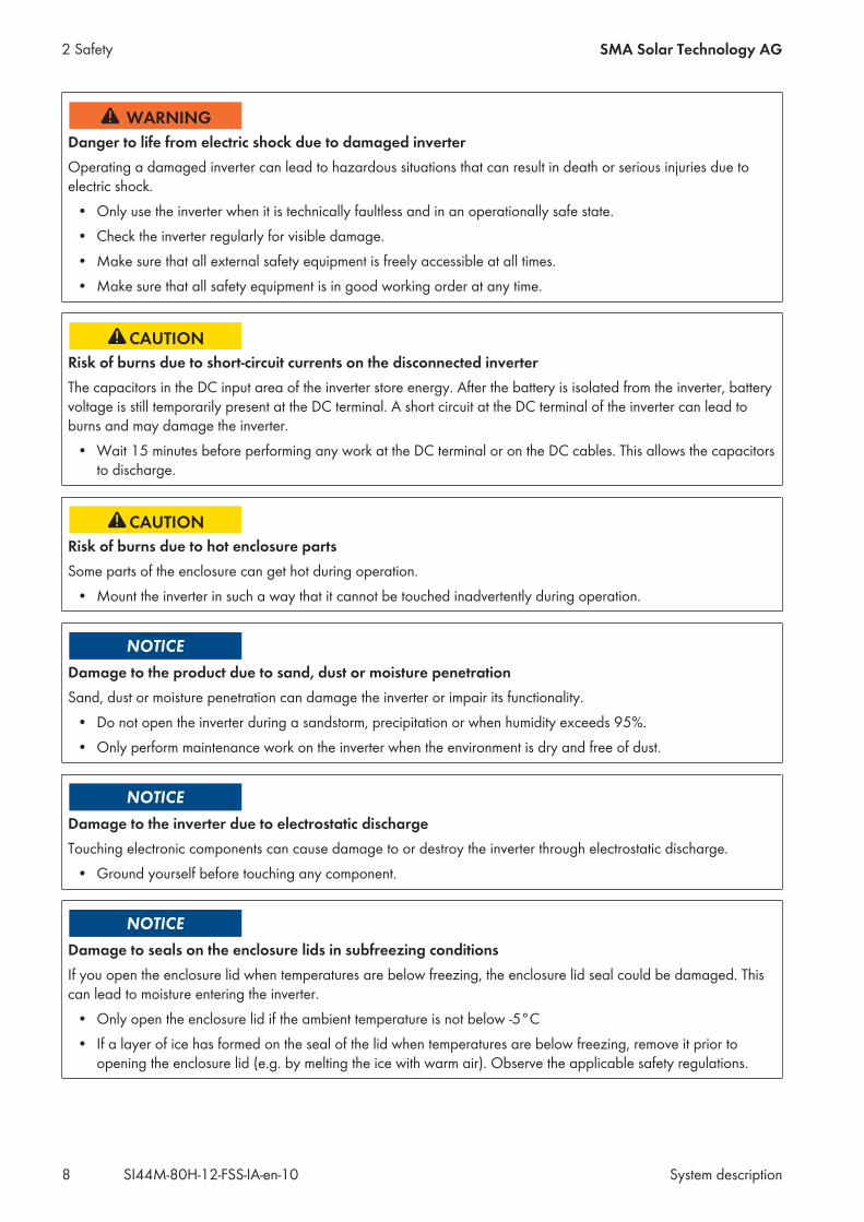
Danger to life from electric shock due to damaged inverterOperating a damaged inverter can lead to hazardous situations that can result in death or serious injuries due toelectric shock.
• Only use the inverter when it is technically faultless and in an operationally safe state.• Check the inverter regularly for visible damage.• Make sure that all external safety equipment is freely accessible at all times.• Make sure that all safety equipment is in good working order at any time.
Risk of burns due to short-circuit currents on the disconnected inverterThe capacitors in the DC input area of the inverter store energy. After the battery is isolated from the inverter, batteryvoltage is still temporarily present at the DC terminal. A short circuit at the DC terminal of the inverter can lead toburns and may damage the inverter.
• Wait 15 minutes before performing any work at the DC terminal or on the DC cables. This allows the capacitorsto discharge.
Risk of burns due to hot enclosure partsSome parts of the enclosure can get hot during operation.
• Mount the inverter in such a way that it cannot be touched inadvertently during operation.
Damage to the product due to sand, dust or moisture penetrationSand, dust or moisture penetration can damage the inverter or impair its functionality.
• Do not open the inverter during a sandstorm, precipitation or when humidity exceeds 95%.• Only perform maintenance work on the inverter when the environment is dry and free of dust.
Damage to the inverter due to electrostatic dischargeTouching electronic components can cause damage to or destroy the inverter through electrostatic discharge.
• Ground yourself before touching any component.
Damage to seals on the enclosure lids in subfreezing conditionsIf you open the enclosure lid when temperatures are below freezing, the enclosure lid seal could be damaged. Thiscan lead to moisture entering the inverter.
• Only open the enclosure lid if the ambient temperature is not below -5°C• If a layer of ice has formed on the seal of the lid when temperatures are below freezing, remove it prior to
opening the enclosure lid (e.g. by melting the ice with warm air). Observe the applicable safety regulations.
2 Safety SMA Solar Technology AG
System descriptionSI44M-80H-12-FSS-IA-en-108

2.3 Battery Safety InformationThis section contains safety information that must be observed at all times when working on or with batteries.To prevent personal injury or property damage and to ensure long-term operation of the batteries, read this sectioncarefully and observe all safety information at all times.
Danger to life due to incompatible lithium-ion batteryAn incompatible lithium-ion battery can lead to a fire or an explosion. With incompatible lithium-ion batteries, it is notensured that battery management is intrinsically safe and will protect the battery.
• Ensure that the lithium-ion batteries are approved for use with the Sunny Island (see technical information “List ofApproved Batteries” at www.SMA-Solar.com).
• If no lithium-ion batteries approved for the inverter can be used, lead-acid batteries can be used.• Verify that the battery complies with locally applicable standards and directives and is intrinsically safe.
Danger to life due to explosive gasesExplosive gases may escape from the battery and cause an explosion.
• Protect the battery environment from open flames, embers and sparks.• Install, operate and maintain the battery in accordance with the manufacturer’s specifications.• Do not burn the battery and do not heat it beyond the permitted temperature.• Additional measures for lead-acid batteries: Ensure that the battery room is sufficiently ventilated.
Chemical burns due to battery electrolyteIf handled inappropriately, battery electrolyte can leak from the battery and cause irritation to the eyes, respiratorysystem and skin.
• Install, operate, maintain and dispose of the battery according to the manufacturer’s specifications.• Whenever working on the battery, wear suitable personal protective equipment such as rubber gloves, an
apron, rubber boots and goggles.• Rinse acid splashes thoroughly for a long time with clear water, and consult a doctor immediately.• If acid fumes have been inhaled, consult a doctor immediately.
Risk of burns due to flashesShort-circuit currents in the battery can cause heat build-up and flashes.
• Remove watches, rings and other metal objects prior to carrying out any work on the battery.• Use insulated tools for all work on the battery.• Do not place tools or metal parts on the battery.
2 SafetySMA Solar Technology AG
System description 9SI44M-80H-12-FSS-IA-en-10
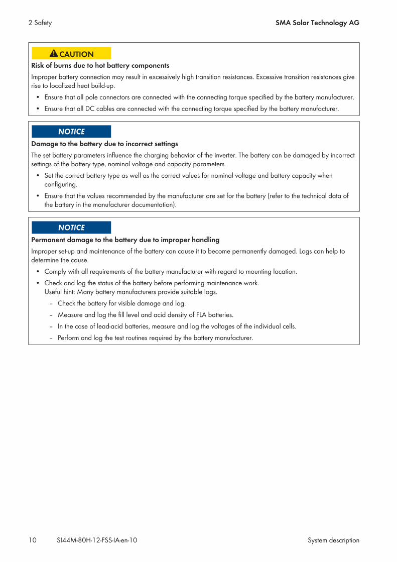
Risk of burns due to hot battery componentsImproper battery connection may result in excessively high transition resistances. Excessive transition resistances giverise to localized heat build-up.
• Ensure that all pole connectors are connected with the connecting torque specified by the battery manufacturer.• Ensure that all DC cables are connected with the connecting torque specified by the battery manufacturer.
Damage to the battery due to incorrect settingsThe set battery parameters influence the charging behavior of the inverter. The battery can be damaged by incorrectsettings of the battery type, nominal voltage and capacity parameters.
• Set the correct battery type as well as the correct values for nominal voltage and battery capacity whenconfiguring.
• Ensure that the values recommended by the manufacturer are set for the battery (refer to the technical data ofthe battery in the manufacturer documentation).
Permanent damage to the battery due to improper handlingImproper set-up and maintenance of the battery can cause it to become permanently damaged. Logs can help todetermine the cause.
• Comply with all requirements of the battery manufacturer with regard to mounting location.• Check and log the status of the battery before performing maintenance work.
Useful hint: Many battery manufacturers provide suitable logs.– Check the battery for visible damage and log.– Measure and log the fill level and acid density of FLA batteries.– In the case of lead-acid batteries, measure and log the voltages of the individual cells.– Perform and log the test routines required by the battery manufacturer.
2 Safety SMA Solar Technology AG
System descriptionSI44M-80H-12-FSS-IA-en-1010

3 Functions and Design
3.1 Functions of the SMA Flexible Storage SystemThe SMA Flexible Storage System supports increased self-consumption through the following measures:
• Intermediate storage of excess PV energy with Sunny Island• Load control and PV system monitoring with Sunny Home Manager
The Sunny Island uses the connected battery for the intermediate storage of excess PV energy. To do this, Sunny Islandmeasures, for example, the grid feed-in and the purchased electricity with the Sunny Home Manager 2.0. The batterymanagement uses this data to regulate the charging and discharging of the battery. The data for the grid feed-in andfor purchased electricity are transmitted to the Sunny Island via Speedwire.If the Sunny Home Manager is connected to the Internet, the Sunny Home Manager receives location-based weatherforecasts and uses them to create yield forecasts for the PV system. In addition, the Sunny Home Manager determineshow much energy is typically consumed in a household at different times of the day and uses this to create a loadprofile of the household. The Sunny Home Manager uses the production forecast and the load profile to determinefavorable times for increased self-consumption and selectively switches, for example, the loads connected to the SMAradio-controlled sockets on and off. If required by the grid operator, the Sunny Home Manager also monitors theactive power feed-in of the PV system. If the set maximum value for active power feed-in is exceeded, theSunny Home Manager sends power reduction commands to the SMA PV inverters.
Preventing Derating LossesThe SMA Flexible Storage System prevents derating losses which may arise due to the limitation of active power feed-in. This is achieved by regulating the operation times of time-independent loads and the time and duration of batterycharging in accordance with the PV production forecast and the consumption forecast.
Example:The current daily forecast of the system predicts a limitation of active power feed-in around noon when the energyrequirement of the loads is very low and PV production is high. For this reason, derating losses can be expected.According to this forecast, the system only begins to charge the battery in the late morning. The derating losses willbe reduced or avoided by charging the battery at this later time. The total excess PV energy generated in themorning will be fed into the utility grid without derating losses (for details on power control, see planning guidelines"SMA Smart Home").
Deactivating the Increased Self-Consumption Function during Certain Charging ProceduresWhen using lead-acid batteries, the SMA Flexible Storage System carries out full and equalization charges on aregular basis (see technical information "Battery Management" at www.SMA-Solar.com). During this charging process,the increased self-consumption function is deactivated and electricity may have to be purchased to perform the full andequalization charges.Regular full and equalization charges increase the service life of lead-acid batteries.
3.2 Requirements of VDE Application Guide 2510-2The requirements below apply only for systems for which the following properties are all applicable:
• The system is a system with increased self-consumption (SMA Flexible Storage System) or a system with increasedself-consumption and battery-backup function (battery-backup system).
• The grid operator or the locally applicable standards and guidelines require compliance with the above-mentioned Application Guide.Currently, only the grid operators in Germany require compliance with the above-mentioned Application Guide.
3 Functions and DesignSMA Solar Technology AG
System description 11SI44M-80H-12-FSS-IA-en-10

In accordance with the scope of VDE application guide 2510-2, a manufacturer's system is regarded as a completeenergy storage system only if products are used that have been approved by the manufacturer (see the technicalinformation “List of Approved Batteries”; for a battery-backup system also refer to the planning guidelines"SMA Flexible Storage System with Battery Backup Function", and for the SMA Flexible Storage System to theplanning guidelines "SMA Smart Home"). If products are used that have not been approved by SMA SolarTechnology AG, the installer is deemed to be the manufacturer of the system.The requirements of VDE application guide 2510-2 are fulfilled if the installation is carried out in accordance with thetechnical documentation of the Sunny Island inverter.
3.3 Requirements for Communication
Requirements for the Speedwire networkThe Sunny Island and the Sunny Home Manager 2.0 can be directly interconnected via Speedwire. If more than twodevices are to communicate via Speedwire or the Sunny Home Manager 2.0 is to establish an internet connection tothe Sunny Portal, a Speedwire network is required.
Requirements:☐ All Speedwire devices must be connected to the same router.☐ The router and the optional network switch must fully support Multicast.☐ The router must support "Internet Enabled Devices" with the SIP and STUN interfaces.
Most common routers and network switches support Multicast and "Internet Enabled Devices".
3 Functions and Design SMA Solar Technology AG
System descriptionSI44M-80H-12-FSS-IA-en-1012

4 System with One Sunny Island
4.1 Circuitry Overview for a System with One Sunny Island Inverter
F1
SU
NN
Y P
OR
TAL
F2
WA
N
SU
NN
Y H
OM
E M
AN
AG
ER 2
.0
Ba
tTm
p+
_D
C
L N
PE
AC
1
Co
mET
H
Co
mS
ync
Out
Co
mS
ync
In
LA
C2
NN
TTPE
F2F1
WLA
N
Lithium-ion battery
Lead-acid battery
UTI
LITY
GRI
D
BA
TTER
Y
DIS
TRIB
UTI
ON
BO
ARD
ROU
TER
Exis
ting
pro
tect
ive
dev
ices
CO
NTR
OLL
AB
LE
LOA
DS
NO
N-
CO
NTR
OLL
AB
LE L
OA
DS
Gro
und
ing
co
nduc
tor
Da
ta c
ab
le
Line
co
nduc
tor
Neu
tral c
ond
ucto
r
DC
+ c
ab
leD
C–
ca
ble
Term
ina
tor
Grid
-co
nnec
tion
po
int
with
ene
rgy
met
er o
f the
elec
tric
util
ity c
om
pa
ny
TN o
r TT
sys
tem
Net
wo
rk c
ab
le S
pee
dw
ire (
LAN
)
* T
he in
dic
ate
d v
alu
es a
re r
eco
mm
end
ed b
y S
MA
So
lar
Tech
nolo
gy
AG
.Th
e el
ectr
ica
l dev
ices
mus
t be
des
igne
d in
acc
ord
anc
e w
ith th
e lo
cally
ap
plic
ab
le s
tand
ard
s a
nd d
irect
ives
.
At
con
ne
ctio
n A
C2
,a
lwa
ys
con
ne
ct t
he
ne
utr
al c
on
du
cto
r to
N.
TTRA
DIO
-C
ON
TRO
LLED
S
OC
KET
Circ
uit b
rea
ker
C 3
2A
*
Resi
dua
l-cur
rent
dev
ice
ype
A*
40
A/0
,03
A t
PV IN
VER
TERS
PV A
RRA
Y
BA
TTER
Y F
US
E
Figure 1: Circuitry of the SMA Flexible Storage System for TN and TT systems
4 System with One Sunny IslandSMA Solar Technology AG
System description 13SI44M-80H-12-FSS-IA-en-10

4.2 Connection of the Sunny Island
NO C NCRelay 1
NO C NCRelay 2
A B C D E F
Figure 2: Connection of the Sunny Island
Position Designation Description / information
A AC power cable Terminal AC2 Gen/Grid terminals L, NTT and PEUtility grid connection with a three-wire cableConductor cross-section: from 6 mm2 to 16 mm2
Only use the supplied ferrite for PE.
B DC+ cable Battery connectionConductor cross-section: from 50 mm2 to 95 mm2
Cable diameters: 14 mm to 25 mmC DC- cable
D Measuring cable of the batterytemperature sensor
Terminal BatTmpYou only have to connect a battery temperature sensor if lead-acidbatteries are used.Mount the battery temperature sensor in the middle of the battery-storage system, in the upper third of the battery cell.Use the supplied ferrite.
4 System with One Sunny Island SMA Solar Technology AG
System descriptionSI44M-80H-12-FSS-IA-en-1014
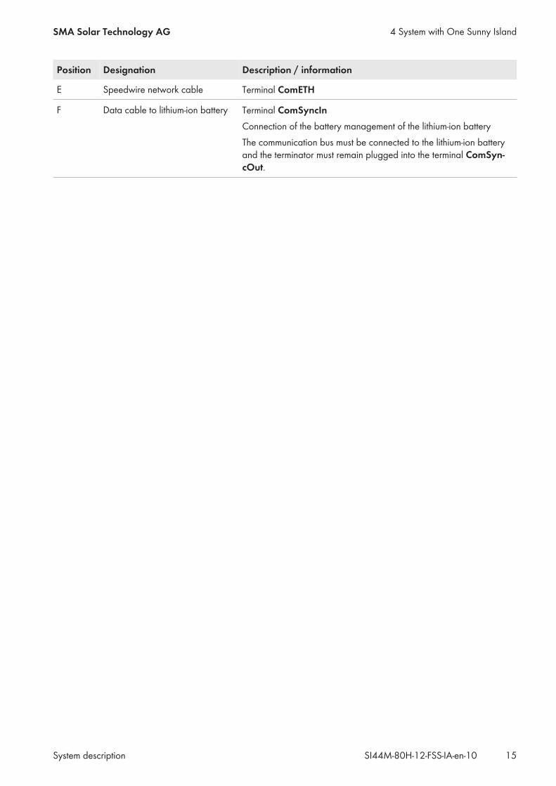
Position Designation Description / information
E Speedwire network cable Terminal ComETH
F Data cable to lithium-ion battery Terminal ComSyncInConnection of the battery management of the lithium-ion batteryThe communication bus must be connected to the lithium-ion batteryand the terminator must remain plugged into the terminal ComSyn-cOut.
4 System with One Sunny IslandSMA Solar Technology AG
System description 15SI44M-80H-12-FSS-IA-en-10

5 System With Three Sunny Island Inverters
5.1 Circuitry Overview for a System with Three Sunny Island Inverters
F1
SU
NN
Y P
OR
TAL
F2
WA
N
F2F1
F1F1 F2 B
atT
mp
+_
DC
L N
PE
AC
1
Dis
pla
y
Co
mS
ync
Out
Co
mS
ync
In
LA
C2
NN
TTPE
F2
Ba
tTm
p+
_D
C
L N
PE
AC
1
Co
mET
H
Co
mS
ync
Out
Co
mS
ync
In
LA
C2
NN
TTPE
Ba
tTm
p+
_D
C
L N
PE
AC
1
Dis
pla
y
Co
mS
ync
Out
Co
mS
ync
In
LA
C2
NN
TTPE
WLA
N
SU
NN
YH
OM
E M
AN
AG
ER 2
.0
Lithium-ion battery
Lead-acid battery
UTI
LITY
GRI
D
BA
TTER
Y
DIS
TRIB
UTI
ON
BO
ARD
ROU
TER
PV IN
VER
TERS
PV A
RRA
Y
Exis
ting
pro
tect
ive
dev
ices
CO
NTR
OLL
AB
LE
LOA
DS
NO
N-
CO
NTR
OLL
AB
LE L
OA
DS
Gro
und
ing
co
nduc
tor
Da
ta c
ab
le
Line
co
nduc
tor
Neu
tral c
ond
ucto
r
DC
+ c
ab
leD
C–
ca
ble
Term
ina
tor
Grid
-co
nnec
tion
po
int
with
ene
rgy
met
er o
f the
elec
tric
util
ity c
om
pa
ny
TN o
r TT
sys
tem
Net
wo
rk c
ab
leS
pee
dw
ire (
LAN
)
* T
he in
dic
ate
d v
alu
es a
re r
eco
mm
end
ed b
y S
MA
So
lar
Tech
nolo
gy
AG
.Th
e el
ectr
ica
l dev
ices
mus
t be
des
igne
d in
acc
ord
anc
e w
ith th
e lo
cally
ap
plic
ab
le
sta
nda
rds
and
dire
ctiv
es.
At
con
ne
ctio
n A
C2
,a
lwa
ys
con
ne
ct t
he
ne
utr
al c
on
du
cto
r to
N.
TTRA
DIO
-C
ON
TRO
LLED
S
OC
KET
Circ
uit b
rea
ker
C 3
2A
*
Resi
dua
l-cur
rent
dev
ice
ype
A*
40
A/0
,03
A t
BA
TTER
Y F
US
E
Figure 3: SMA Flexible Storage System for TN and TT systems
5 System With Three Sunny Island Inverters SMA Solar Technology AG
System descriptionSI44M-80H-12-FSS-IA-en-1016
5.2 Connecting the Master
NO C NCRelay 1
NO C NCRelay 2
A B C D E FG
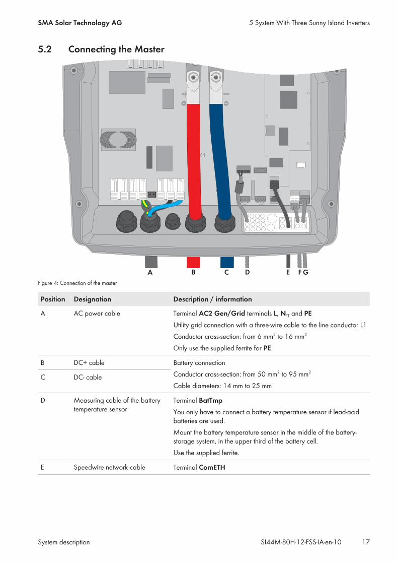
Figure 4: Connection of the master
Position Designation Description / information
A AC power cable Terminal AC2 Gen/Grid terminals L, NTT and PEUtility grid connection with a three-wire cable to the line conductor L1Conductor cross-section: from 6 mm2 to 16 mm2
Only use the supplied ferrite for PE.
B DC+ cable Battery connectionConductor cross-section: from 50 mm2 to 95 mm2
Cable diameters: 14 mm to 25 mmC DC- cable
D Measuring cable of the batterytemperature sensor
Terminal BatTmpYou only have to connect a battery temperature sensor if lead-acidbatteries are used.Mount the battery temperature sensor in the middle of the battery-storage system, in the upper third of the battery cell.Use the supplied ferrite.
E Speedwire network cable Terminal ComETH
5 System With Three Sunny Island InvertersSMA Solar Technology AG
System description 17SI44M-80H-12-FSS-IA-en-10

Position Designation Description / information
F Data cable to lithium-ion battery Terminal ComSyncInConnection of the battery management of the lithium-ion batteryThe communication bus must be connected to the lithium-ion battery.If no lithium-ion batteries are used, plug the terminator into the termi-nal ComSyncIn.
G Data cable for the internal com-munication in the cluster
Terminal ComSyncOutConnection of internal communication bus of Slave 1
5.3 Connecting the Slaves
NO C NCRelay 1
NO C NCRelay 2
A B C D E
Figure 5: Connection of the slave
Position Designation Description / information
A AC power cable Terminal AC2 Gen/Grid terminals L, NTT and PEUtility grid connection with a three-wire cableConnect slave 1 to line conductor L2, connect slave 2 to line conduc-tor L3.Conductor cross-section: from 6 mm2 to 16 mm2
Only use the supplied ferrite for PE.
5 System With Three Sunny Island Inverters SMA Solar Technology AG
System descriptionSI44M-80H-12-FSS-IA-en-1018

Position Designation Description / information
B DC+ cable Battery connectionConductor cross-section: from 50 mm2 to 95 mm2
Cable diameters: 14 mm to 25 mmC DC- cable
D Data cable for the internal com-munication in the cluster
Terminal ComSyncInWith slave 1: connection of internal communication bus of the masterWith slave 2: connection of internal communication bus of slave 1
E Data cable for the internal com-munication in the cluster
Terminal ComSyncOutWith slave 1: connection of internal communication bus of slave 2With slave 2: leave terminator plugged in. Slave 2 is connected toslave 1 only.
5 System With Three Sunny Island InvertersSMA Solar Technology AG
System description 19SI44M-80H-12-FSS-IA-en-10

6 Commissioning
6.1 Commissioning ProcedureBefore commissioning the system, you must make various settings. This section describes the procedure and gives anoverview of the steps, which must always be performed in the prescribed sequence.
Procedure See
1. Commission the inverter. Sunny Island operating manual
2. Establish a connection to the user interface of the inverter. There arethe following connection options available to choose from:
• Direct connection via WLAN• Direct connection via Ethernet• Connection via Ethernet in the local network
Sunny Island operating manual
3. Log into the user interface. Sunny Island operating manual
4. Perform the basic configuration via the installation assistant:• Single system (system with one Sunny Island)• Single-cluster-system (system with three Sunny Island)
Please note, that the personal SMA Grid Guard code for changingthe grid-relevant parameters must be available after completion ofthe first ten operating hours (see "Application for theSMA Grid Guard code" available at www.SMA-Solar.com).
Sunny Island operating manual
5. Adjust the configuration of the Sunny Island. Section 6.2, page 20
6. Commission the SMA Flexible Storage System Section 6.3, page 22
6.2 Adjusting the Configuration of the Sunny IslandIn the SMA Flexible Storage System, the Sunny Island inverters are connected to the utility grid and must meet therequirements of the grid operators. The Sunny Island inverters fulfill the requirements of application guide VDE-AR-N4105:2011-08. In the Sunny Island, this application guide is defined as standard country data set VDE-AR-4105.The configuration must be adjusted as follows for Denmark, Austria and Switzerland (status as of June 2017):
Country Operating condition Parameters Set value
Denmark When using the Sunny Island 6.0H /8.0H, the discharge/charging currentmust be reduced.
Maximum AC battery charging current 16.0 A
When using the Sunny Island 4.4M,you can retain the default setting of thedischarge/charging current.
– –
6 Commissioning SMA Solar Technology AG
System descriptionSI44M-80H-12-FSS-IA-en-1020

Country Operating condition Parameters Set value
Austria If your grid operator does not permitfrequency-dependent control of activepower feed-in in the case of overfre-quency, this function must be deacti-vated (see VDE-AR-N 4105 item5.7.3.3).
Operating mode of active power limita-tion in the case of overfrequency P(f)
Off
If your grid operator specifies a maxi-mum grid feed-in per line conductor,the electric discharge/charging currentmust be reduced.
Maximum AC battery charging current Grid operatorspecifications
Switzerland The maximum grid frequency must beobserved.
Frequency monitoring upper maximumthreshold
50.2 Hz
The upper frequency difference forvalid grid connection must be ob-served.
Frequency monitoring hysteresis maxi-mum threshold
0.05 Hz
The minimum observation time for gridvoltage and frequency before grid con-nection must be observed.
Grid monitoring time 30 s
If your grid operator specifies a maxi-mum grid feed-in per line conductor,the electric discharge/charging currentmust be reduced.
Maximum AC battery charging current Grid operatorspecifications
In Belgium and Germany, the configuration may only be adjusted upon request or with permission of the grid operator(status: June 2017):Use in other countries is possible with the agreement of the grid operator. Consult the grid operator on whetheradjustment is necessary.
Requirements:☐ The grid-relevant parameters must be changed within the first ten operating hours of the inverter, otherwise the
SMA Grid Guard code must be available (see "Application for SMA Grid Guard Code" at http://www.SMA-Solar.com).
☐ The parameter Set country standard must be set to VDE-AR-N4105.
Procedure:1. Activate the user interface of the inverter (see the inverter operating manual).2. Log in as Installer.3. Adjust the parameters for Denmark, Austria or Switzerland (see the Sunny Island operating manual).4. When installing in Switzerland, attach the label "VDE 0126-1-1" next to the type label of the Sunny Island
inverter.
6 CommissioningSMA Solar Technology AG
System description 21SI44M-80H-12-FSS-IA-en-10
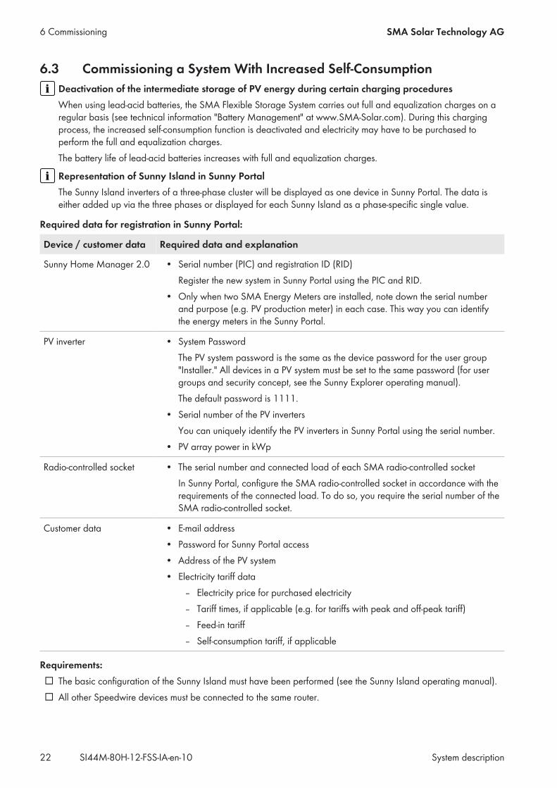
6.3 Commissioning a System With Increased Self-ConsumptionDeactivation of the intermediate storage of PV energy during certain charging proceduresWhen using lead-acid batteries, the SMA Flexible Storage System carries out full and equalization charges on aregular basis (see technical information "Battery Management" at www.SMA-Solar.com). During this chargingprocess, the increased self-consumption function is deactivated and electricity may have to be purchased toperform the full and equalization charges.The battery life of lead-acid batteries increases with full and equalization charges.
Representation of Sunny Island in Sunny PortalThe Sunny Island inverters of a three-phase cluster will be displayed as one device in Sunny Portal. The data iseither added up via the three phases or displayed for each Sunny Island as a phase-specific single value.
Required data for registration in Sunny Portal:
Device / customer data Required data and explanation
Sunny Home Manager 2.0 • Serial number (PIC) and registration ID (RID)Register the new system in Sunny Portal using the PIC and RID.
• Only when two SMA Energy Meters are installed, note down the serial numberand purpose (e.g. PV production meter) in each case. This way you can identifythe energy meters in the Sunny Portal.
PV inverter • System PasswordThe PV system password is the same as the device password for the user group"Installer." All devices in a PV system must be set to the same password (for usergroups and security concept, see the Sunny Explorer operating manual).The default password is 1111.
• Serial number of the PV invertersYou can uniquely identify the PV inverters in Sunny Portal using the serial number.
• PV array power in kWp
Radio-controlled socket • The serial number and connected load of each SMA radio-controlled socketIn Sunny Portal, configure the SMA radio-controlled socket in accordance with therequirements of the connected load. To do so, you require the serial number of theSMA radio-controlled socket.
Customer data • E-mail address• Password for Sunny Portal access• Address of the PV system• Electricity tariff data
– Electricity price for purchased electricity– Tariff times, if applicable (e.g. for tariffs with peak and off-peak tariff)– Feed-in tariff– Self-consumption tariff, if applicable
Requirements:☐ The basic configuration of the Sunny Island must have been performed (see the Sunny Island operating manual).☐ All other Speedwire devices must be connected to the same router.
6 Commissioning SMA Solar Technology AG
System descriptionSI44M-80H-12-FSS-IA-en-1022

☐ The router must meet the requirements for the design of a Speedwire communication network (see Section 3.3,page 12).
Procedure:1. In the distribution board, switch on circuit breaker F1 and residual-current device F2.2. Commission the PV system (see PV inverter documentation).3. Press the start-stop button on the Sunny Island and hold it until
an acoustic signal sounds. This starts the system.
4. Only when one Sunny Home Manager 2.0 and one SMA Energy Meter are installed in the local network, assignthe grid feed-in meter and purchased electricity meter to the Sunny Island via the user interface. To do this, enterthe serial number of the grid feed-in meter and purchased electricity meter (see the Sunny Explorer operatingmanual).
5. Open Sunny Portal via http://www.SunnyPortal.com/Register and run the PV System Setup Assistant. Therequired data for registration in Sunny Portal must be at hand.
6. Activate the automatic update of the Sunny Home Manager and the PV system in Sunny Portal.7. In order to activate the forecast-based charging function, call up the device properties of the
Sunny Home Manager in Sunny Portal and activate the Forecast-based battery charging checkbox. For furtherinformation on the forecast-based battery charging, see planning guidelines "SMA Smart Home").
8. Only in systems with active power limitation, ensure that the limitation of the active power feed-in is configuredand functioning in Sunny Portal ("Configuring Active Power Feed-In Limitation", see the operating manual"Sunny Home Manager in Sunny Portal" at http://www.SunnyPortal.com).
6 CommissioningSMA Solar Technology AG
System description 23SI44M-80H-12-FSS-IA-en-10

7 ContactIf you have technical problems with our products, please contact the SMA Service Line. We require the followinginformation in order to provide you with the necessary assistance:
• Type of system installed (e.g., three-phase single-cluster system)• Number and type of the Sunny Island inverters• Serial number of the Sunny Island inverters• Firmware version of the Sunny Island inverters• Error message displayed• Type of battery connected• Nominal battery capacity• Nominal battery voltage• Type of the communication products connected• Type and size of additional energy sources• If a generator is connected:
– Type– Power– Maximum current
• If a Multicluster-Box is connected, device type of the Multicluster-BoxIn order to receive service assignments for the Sunny Island system, all system data must be recorded in the informationsheet for Sunny Island systems during commissioning and made available to Service (for information sheet seewww.SMA-Solar.com).
DeutschlandÖsterreichSchweiz
SMA Solar Technology AGNiestetalSunny Boy, Sunny Mini Central,Sunny Tripower: +49 561 9522‑1499Monitoring Systems(Kommunikationsprodukte):+49 561 9522‑2499Fuel Save Controller(PV-Diesel-Hybridsysteme):+49 561 9522-3199Sunny Island, Sunny Boy Storage,Sunny Backup:+49 561 9522-399Sunny Central, Sunny Central Storage: +49 561 9522-299SMA Online Service Center:www.SMA-Service.com
BelgienBelgiqueBelgiëLuxemburgLuxembourgNederland
SMA Benelux BVBA/SPRLMechelen+32 15 286 730SMA Online Service Center:www.SMA-Service.com
ČeskoMagyarországSlovensko
SMA Service Partner TERMS a.s.+420 387 6 85 111SMA Online Service Center:www.SMA-Service.com
Türkiye SMA Service Partner DEKOM Ltd. Şti.+90 24 22430605SMA Online Service Center:www.SMA-Service.com
France SMA France S.A.S.Lyon+33 472 22 97 00SMA Online Service Center :www.SMA-Service.com
ΕλλάδαΚύπρος
SMA Service Partner AKTOR FM.Αθήνα+30 210 8184550SMA Online Service Center:www.SMA-Service.com
7 Contact SMA Solar Technology AG
System descriptionSI44M-80H-12-FSS-IA-en-1024
EspañaPortugal
SMA Ibérica Tecnología Solar, S.L.U.Barcelona+34 935 63 50 99SMA Online Service Center:www.SMA-Service.com
United Kingdom SMA Solar UK Ltd.Milton Keynes+44 1908 304899SMA Online Service Center:www.SMA-Service.com
Italia SMA Italia S.r.l.Milano+39 02 8934-7299SMA Online Service Center:www.SMA-Service.com
Australia SMA Australia Pty Ltd.SydneyToll free for Australia:1800 SMA AUS(1800 762 287)International: +61 2 9491 4200
United ArabEmirates
SMA Middle East LLCAbu Dhabi+971 2234 6177SMA Online Service Center:www.SMA-Service.com
India SMA Solar India Pvt. Ltd.Mumbai+91 22 61713888
SMA Solar (Thailand) Co., Ltd.
+66 2 670 6999
대한민국 SMA Technology Korea Co., Ltd.서울+82-2-520-2666
South Africa SMA Solar Technology South AfricaPty Ltd.Cape Town08600SUNNY (08600 78669)International: +27 (0)21 826 0600SMA Online Service Center:www.SMA-Service.com
ArgentinaBrasilChilePerú
SMA South America SPASantiago de Chile+562 2820 2101
Other coun-tries
International SMA Service LineNiestetal00800 SMA SERVICE(+800 762 7378423)SMA Online Service Center:www.SMA-Service.com
7 ContactSMA Solar Technology AG
System description 25SI44M-80H-12-FSS-IA-en-10

www.SMA-Solar.com