system design and blueprint - pa - emarketplace system design and blueprint version 2.4 ... 6.3...
TRANSCRIPT

System Design and Blueprint
Version 2.4
for
UCMS Wage and Tax Applications
Support and Maintenance
Prepared for
Commonwealth of Pennsylvania
Department of Labor and Industry
April 8, 2016
International Business Machines Corporation
Commonwealth of Pennsylvania | Unemployment Compensation Modernization System System Design and Blueprint – Updated April 2016 Copyright 2016, Commonwealth of Pennsylvania. All Rights Reserved.
i
Revision History
Release/
Version Information
Revision Date
Author / Editor Summary of Changes
1.2 07-18-07 Don Chavey Incorporated correction from 2nd walkthrough
2.0 12-02-14 John Drabik Updated to reflect the UCMS production system
2.1 12-23-14 John Drabik Updated to incorporate comments from DLI
2.2 04-10-15 Bob Pratt Updated with Comments from DLI
2.3 03-03-16 Bob Pratt Revised to reflect new AEM Portal and other product upgrades
2.4 04-08-16 Scott Nelson Revisions for AEM Portal, BPM, LiveCycle migrations and other minor edits.

Commonwealth of Pennsylvania | Unemployment Compensation Modernization System System Design and Blueprint – Updated April 2016 Copyright 2016, Commonwealth of Pennsylvania. All Rights Reserved.
ii
Table of Contents
1.0 Introduction........................................................................................................................................ 1
1.1 Purpose ................................................................................................................................. 1 1.2 Scope ..................................................................................................................................... 1 1.3 References ............................................................................................................................ 1 1.4 Overview ............................................................................................................................... 2
2.0 Ground Rules ..................................................................................................................................... 3
2.1 Introduction .......................................................................................................................... 3 2.2 Architectural Principles ....................................................................................................... 3
2.2.1 Introduction ............................................................................................................................. 3 2.2.2 Principles Summary ............................................................................................................... 3
2.3 Architectural Decisions ....................................................................................................... 5 2.3.1 Introduction ............................................................................................................................. 5 2.3.2 Decisions Summary ............................................................................................................... 5
2.4 Architectural Standards .................................................................................................... 10 2.4.1 Introduction ........................................................................................................................... 10 2.4.2 Standards Summary ............................................................................................................ 11
3.0 Solution Overview ........................................................................................................................... 12
3.1 Introduction ........................................................................................................................ 12 3.2 System Context .................................................................................................................. 12
3.2.1 Introduction ........................................................................................................................... 12 3.2.2 System Context Diagram ..................................................................................................... 13 3.2.3 External Entities .................................................................................................................... 14 3.2.4 Interface Summary ............................................................................................................... 19
3.3 Service-Oriented Architecture .......................................................................................... 22 3.3.1 Introduction ........................................................................................................................... 22 3.3.2 SOA Layered Model ............................................................................................................. 22 3.3.3 UCMS SOA Illustration......................................................................................................... 24 3.3.4 UCMS Common Modules .................................................................................................... 25 3.3.5 Services in SOA.................................................................................................................... 25 3.3.6 SOA Infrastructure ................................................................................................................ 27
4.0 Component Architecture ................................................................................................................ 30
4.1 Introduction ........................................................................................................................ 30 4.1.1 UCMS Conceptual Component Model ............................................................................... 32 4.1.2 UCMS Specification Component Model ............................................................................. 34
4.2 Application Services .......................................................................................................... 35 4.2.1 Introduction ........................................................................................................................... 35 4.2.2 Configuration Management ................................................................................................. 38 4.2.3 Model-View-Controller .......................................................................................................... 44 4.2.4 Data Access .......................................................................................................................... 56 4.2.5 Caching 60

Commonwealth of Pennsylvania | Unemployment Compensation Modernization System System Design and Blueprint – Updated April 2016 Copyright 2016, Commonwealth of Pennsylvania. All Rights Reserved.
iii
4.2.6 Exception Handling .............................................................................................................. 65 4.2.7 Logging 67 4.2.8 Messaging ............................................................................................................................. 74 4.2.9 Security 81
4.3 Portal Services ................................................................................................................... 85 4.3.1 Introduction ........................................................................................................................... 85 4.3.2 Component Overview........................................................................................................... 86 4.3.3 Key Concepts, Features and Capabilities .......................................................................... 89
4.4 Workflow ............................................................................................................................. 90 4.4.1 Introduction ........................................................................................................................... 90 4.4.2 Component Overview........................................................................................................... 91 4.4.3 Run-Time .............................................................................................................................. 91 4.4.4 Key Concepts, Features and Capabilities .......................................................................... 96
4.5 Enterprise Service Bus .................................................................................................... 101 4.5.1 Introduction ........................................................................................................................ 101 4.5.2 Component Overview........................................................................................................ 102 4.5.3 Key Concepts, Features and Capabilities ....................................................................... 104
4.6 Business Rules ................................................................................................................ 107 4.6.1 Introduction ........................................................................................................................ 107 4.6.2 Component Overview........................................................................................................ 108 4.6.3 Key Concepts, Features and Capabilities ....................................................................... 111
4.7 Document Management ................................................................................................... 112 4.7.1 Introduction ........................................................................................................................ 112 4.7.2 Component Overview........................................................................................................ 113 4.7.3 Key Concepts, Features and Capabilities ....................................................................... 115
4.8 Correspondence Management........................................................................................ 118 4.8.1 Introduction ........................................................................................................................ 118 4.8.2 Component Overview........................................................................................................ 119 4.8.3 Key Concepts, Features and Capabilities ....................................................................... 124
4.9 Reporting .......................................................................................................................... 126 4.9.1 Introduction ........................................................................................................................ 126 4.9.2 Component Overview........................................................................................................ 127 4.9.3 Key Concepts, Features and Capabilities ....................................................................... 132
4.10 Wage Functionality Component Model .......................................................................... 139 4.10.1 Introduction ........................................................................................................................ 139 4.10.2 Component Overview........................................................................................................ 140 4.10.3 Component Relationships ................................................................................................. 141 4.10.4 Component Descriptions................................................................................................... 144 4.10.5 Component Interaction ...................................................................................................... 145
4.11 Tax Component Model ..................................................................................................... 151 4.11.1 Introduction ........................................................................................................................ 151
5.0 Data Architecture .......................................................................................................................... 152
5.1 Introduction ...................................................................................................................... 152 5.1.1 Key Assumptions ............................................................................................................... 152 5.1.2 Key Requirements ............................................................................................................. 153

Commonwealth of Pennsylvania | Unemployment Compensation Modernization System System Design and Blueprint – Updated April 2016 Copyright 2016, Commonwealth of Pennsylvania. All Rights Reserved.
iv
5.2 Data Architecture Framework ......................................................................................... 153 5.3 High-Level Physical Data Architecture .......................................................................... 156
5.3.1 Data Stores ........................................................................................................................ 157 5.3.2 Data Store Characteristics and Mappings ....................................................................... 161
5.4 Technical Data Architecture............................................................................................ 163 5.4.1 High Availability .................................................................................................................. 163 5.4.2 Disaster Recovery ............................................................................................................. 165 5.4.3 Backup and Recovery ....................................................................................................... 166 5.4.4 Operational Considerations .............................................................................................. 166
6.0 Security & Privacy Architecture .................................................................................................. 170
6.1 Introduction ...................................................................................................................... 170 6.2 Security Design Principles .............................................................................................. 170 6.3 Business-level Security Requirements .......................................................................... 172 6.4 Overarching Architectural Decisions ............................................................................. 172 6.5 UCMS Conceptual Security Architecture ...................................................................... 173 6.6 UCMS Logical Security Architecture ............................................................................. 176
6.6.1 Policy Application Footprint ............................................................................................... 179 6.7 UCMS Physical Security Architecture ........................................................................... 180
6.7.1 Security Zones ................................................................................................................... 181 6.8 Security Design ................................................................................................................ 184
6.8.1 Identity Services ................................................................................................................ 184 6.8.2 Authentication and Authorization Services ...................................................................... 186 6.8.3 Confidentiality and Integrity Services ............................................................................... 190 6.8.4 Audit and Logging Services .............................................................................................. 191
7.0 Operational Architecture .............................................................................................................. 193
7.1 Introduction ...................................................................................................................... 193 7.1.1 Identification ....................................................................................................................... 193 7.1.2 Description ......................................................................................................................... 193 7.1.3 Purpose 194
7.2 System Topology Diagrams ............................................................................................ 195 7.2.1 Physical Infrastructure Topology Diagram ....................................................................... 195 7.2.2 Logical/Functional Infrastructure Topology Diagram ...................................................... 197
7.3 Node Description ............................................................................................................. 200 7.3.1 IBM pSeries Hardware ...................................................................................................... 200 7.3.2 IBM xSeries Hardware ...................................................................................................... 201
7.4 Connection Descriptions ................................................................................................. 202 7.4.1 Network Switches .............................................................................................................. 202 7.4.2 Network Firewalls and Routers......................................................................................... 203 7.4.3 Storage Area Network (SAN) Switches ........................................................................... 203
7.5 Node-Deployment Unit Mapping..................................................................................... 203 7.5.1 Node-Deployment Units .................................................................................................... 204
7.6 Middleware ........................................................................................................................ 204 7.7 Walkthroughs ................................................................................................................... 205
8.0 Systems Management Architecture ............................................................................................ 205

Commonwealth of Pennsylvania | Unemployment Compensation Modernization System System Design and Blueprint – Updated April 2016 Copyright 2016, Commonwealth of Pennsylvania. All Rights Reserved.
v
8.1 Introduction ...................................................................................................................... 205 8.1.1 Management Consoles ..................................................................................................... 207 8.1.2 Management Agents ......................................................................................................... 208
8.2 Systems Management Component Model ..................................................................... 209 8.3 IBM Tivoli Monitoring Components................................................................................ 210
8.3.1 Enterprise Monitoring Server (TEMS) .............................................................................. 210 8.3.2 Tivoli Enterprise Portal Server (TEPS) ............................................................................ 211 8.3.3 Tivoli Enterprise Portal (TEP) ........................................................................................... 211 8.3.4 Tivoli Enterprise Management Agent (TEMA)................................................................. 211 8.3.5 ITM Firewall Gateway Feature ......................................................................................... 211 8.3.6 Tivoli Data Warehouse (TDW) ......................................................................................... 212
8.4 ITCAM for Response Time Tracking Components ....................................................... 212 8.4.1 Management Server .......................................................................................................... 212 8.4.2 Store and Forward Agent .................................................................................................. 212 8.4.3 Management Agents ......................................................................................................... 213
8.5 ITCAM for Application Diagnostics Components ......................................................... 213 8.5.1 Management Server .......................................................................................................... 213 8.5.2 Management Agents ......................................................................................................... 213
8.6 Existing Solution Components ....................................................................................... 213 8.6.1 Tivoli Omnibus ................................................................................................................... 213 8.6.2 IBM Tivoli NetView ............................................................................................................ 213 8.6.3 ServiceNow ........................................................................................................................ 214
8.7 Backup and Recovery ...................................................................................................... 214 8.7.1 Backup/Restore Strategy .................................................................................................. 214
8.8 Change Control and Configuration Management ......................................................... 216 8.9 Performance and Capacity .............................................................................................. 217 8.10 Other Systems Management Processes ........................................................................ 218
9.0 Appendices .................................................................................................................................... 220
9.1 Glossary of Acronyms ..................................................................................................... 220 9.2 Business and Support Walkthroughs ............................................................................ 222
9.2.1 Business Walkthroughs .................................................................................................... 222 9.2.2 System Support Walkthroughs ......................................................................................... 227

Commonwealth of Pennsylvania | Unemployment Compensation Modernization System System Design and Blueprint - Updated April 2016 Copyright 2016, Commonwealth of Pennsylvania. All Rights Reserved.
1
1.0 Introduction
1.1 Purpose
This document serves as a reference for architectural decisions, principles, standards, and component definitions for the UCMS project. It defines the key elements of the Unemployment Compensation Management System (UCMS) architecture thereby serving as the basis for the design and construction of UCMS applications In addition, this document describes the key architectural components of the UCMS architecture and provides a comprehensive architectural overview of the system. The primary purpose of the System Design & Blueprint is to document and explain the key architectural design decisions and the impact of those decisions on the entire solution.
The target audience is primarily technical developers and business analysts who need to understand operational characteristics, or aspects of the associated infrastructure and solution to maintain or enhance unemployment compensation operations.
Managers and senior non-technical staff may find that the document provides a glimpse into the solution structure, and the many pieces and interrelationships involved in formulating the solution.
The UCMS application architecture is based on Service Oriented Architecture (SOA). The primary goal of SOA is to align business needs with information technology in a way that makes it more flexible and effective. SOA is an application architecture that allows business applications to be decomposed into loosely-coupled functions and processes, referred to as services, which can be reused and combined into SOA based applications. UCMS applications are implemented as SOA based applications.
This update to the System Design Blueprint reflects the transition from a design-oriented document, to a document focused on the as-built and as-delivered UCMS solution. Some in-process functional and component changes are included and the document has been updated to reflect the fact that UCMS is in the sustainment phase of its life cycle, where the focus is on maintenance, enhancements and component upgrades.
1.2 Scope
The scope of this document is limited to the architecture of the production Unemployment Compensation Modernization System primarily focused on Wage and Tax business functions.
The document scope includes some architectural components and systems that are the responsibility of the Department of Labor and Industry (DLI) as shared components or are the responsibility of the Office of Administration/Office of Information Technology (OA/OIT) and are shared with other Commonwealth of PA programs.
As a blueprint, this document is intended to provide technical personnel with an overarching view of the UCMS solution. DLI personnel with knowledge of the as-implemented components and functions should keep this document up to date to reflect as-is characteristics, on an ongoing basis as the solution components and infrastructure are updated or changed.
1.3 References
The following documents were referenced in the original System Design & Blueprint:
DLI Systems Management Plan

Commonwealth of Pennsylvania | Unemployment Compensation Modernization System System Design and Blueprint - Updated April 2016 Copyright 2016, Commonwealth of Pennsylvania. All Rights Reserved.
2
Architectural Decisions are located in the Rational ClearCase repository for the PA UCMS project.
1.4 Overview
The Design Blueprint defines architectural principles, decisions and standards, used to design and develop the UCMS suite of applications. The purpose of this document is to define the ground rules and scope of the architecture while capturing details associated with key architectural decisions, including updates reflecting changes since the original Blueprint release. The initial sections of the document define the architecture principles and decisions which constituted the ground rules for the project design.
In addition to the ground rules, the scope of the architecture is further defined by use of the system context. A system context diagram is provided to identify the external systems, information, and control flows required by UCMS applications and crossing UCMS system boundaries. A thorough review of the solution context is a prerequisite for fully understanding the UCMS solution. The System Context diagram also provides some insight into the business and shared infrastructure implementation complexity and its reflection in the UCMS design and implementation.
UCMS applications are designed and implemented as a suite of SOA based applications and services. The implications of SOA on the overall architecture are discussed with an emphasis on how SOA applies to UCMS, and how the SOA layers map to different components of the architecture including the infrastructure required to support SOA applications. An example is provided that describes how SOA Services in Release 0 Common Modules, served as the foundation for subsequent UCMS application releases R1 and R2 (Wage and Tax).
A significant portion of the document is focused on the definition and integration of architectural components defined in the UCMS Component Model. The UCMS Component Model describes the components for each release in terms of their responsibilities, interfaces, relationships, and collaboration to provide business functionality. It describes the specifications for key architecture components such as the Portal, the Enterprise Service Bus (ESB), Workflow/Choreography, Document Management, Correspondence Management, and Reporting. In addition, the UCMS Framework is discussed to describe how framework components in general are used to implement UCMS applications and application services.
In addition to the SOA architecture, the UCMS Enterprise Data, Security, and Operations Architectures are discussed. The Enterprise Data Architecture addresses the data stores, data flows and infrastructure configurations required to support application data requirements. The Security Architecture defines the principles of information security and describes how they are applied. The UCMS Operational Architecture describes the physical infrastructure required to support and deploy UCMS application and service solutions. Since the time UCMS was designed there have been solution changes including changes driven by legislative changes, business enhancements and updates to address growth and complexity of certain record types that are discussed in this document.
The UCMS systems management strategy is also discussed to describe how UCMS infrastructure, systems, and applications components are designed to be proactively monitored and managed to achieve system service levels as they are defined. A detailed management approach to establishing and managing system service levels has not been formally established by DLI, leaving the objectives described in the system design to be to be viewed primarily as guidelines.

Commonwealth of Pennsylvania | Unemployment Compensation Modernization System System Design and Blueprint - Updated April 2016 Copyright 2016, Commonwealth of Pennsylvania. All Rights Reserved.
3
2.0 Ground Rules
2.1 Introduction
The UCMS architecture embodies a set of high-level principles, key design decisions and adherence to recognized technical standards. High-level principles establish an architectural vision of UCMS and create a common understanding of the desired characteristics of the system by capturing the fundamental axioms about the system as it was designed. Key technology and business decisions impact the overall design and implementation of UCMS while providing a mechanism for enforcing and managing adherence to standards. Recognized technical standards are used to promote a consistent use of technology and provide a guide for organizations to follow and document any pre-determined technology components and regulations that must be utilized.
2.2 Architectural Principles
2.2.1 Introduction
Architecture Principles define the general rules and guidelines that were used by UCMS business and technical teams to define the overall architecture and design of UCMS applications. Each Principle includes a statement describing the associated benefits and implications.
The benefit statements highlight the value of implementing the principle.
The implication statements outline the impact of the principle.
Principles are used to capture the fundamental, underlying aspects of the system. Architecture principles provide the following benefits:
Provide an effective framework within which the business managers can make conscious decisions about the business, its management style and structure and how it uses/implements Information Technology.
Act as a guide to establishing relevant evaluation criteria, and exert a strong influence on the overall system design including the selection of vendor products and services.
Serve as drivers for scoping and defining both functional and non-functional requirements of the system.
Help identify transition activities needed to implement new technology in support of business and technology goals, including modernization efforts such as those in the Product and Architecture and Infrastructure Modernization Roadmaps.
Provide benefit statements as a basis for analyzing proposed decisions and related activities.
Implication statements describe the impact on the business and technology for each principle. Principles provide valuable information that is useful during transition initiatives and planning activities resulting from the implementation of a principle.
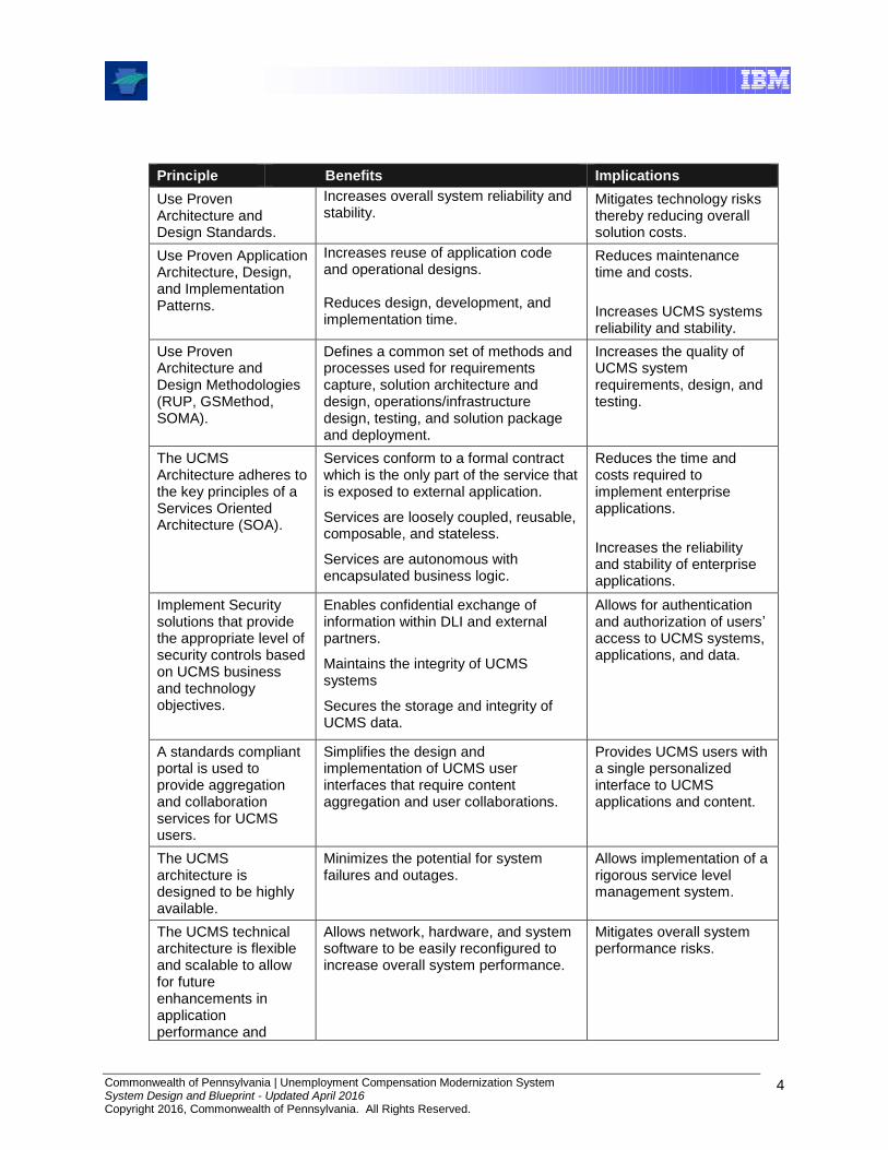
2.2.2 Principles Summary
The following table summarizes the Architectural Principles for the UCMS project. These principles are a combination of IBM best practices, original RFP requirements and items included in the original RFP response.
Commonwealth of Pennsylvania | Unemployment Compensation Modernization System System Design and Blueprint - Updated April 2016 Copyright 2016, Commonwealth of Pennsylvania. All Rights Reserved.
4
Principle Benefits Implications
Use Proven Architecture and Design Standards.
Increases overall system reliability and stability.
Mitigates technology risks thereby reducing overall solution costs.
Use Proven Application Architecture, Design, and Implementation Patterns.
Increases reuse of application code and operational designs. Reduces design, development, and implementation time.
Reduces maintenance time and costs.
Increases UCMS systems reliability and stability.
Use Proven Architecture and Design Methodologies (RUP, GSMethod, SOMA).
Defines a common set of methods and processes used for requirements capture, solution architecture and design, operations/infrastructure design, testing, and solution package and deployment.
Increases the quality of UCMS system requirements, design, and testing.
The UCMS Architecture adheres to the key principles of a Services Oriented Architecture (SOA).
Services conform to a formal contract which is the only part of the service that is exposed to external application.
Services are loosely coupled, reusable, composable, and stateless.
Services are autonomous with encapsulated business logic.
Reduces the time and costs required to implement enterprise applications.
Increases the reliability and stability of enterprise applications.
Implement Security solutions that provide the appropriate level of security controls based on UCMS business and technology objectives.
Enables confidential exchange of information within DLI and external partners.
Maintains the integrity of UCMS systems
Secures the storage and integrity of UCMS data.
Allows for authentication and authorization of users’ access to UCMS systems, applications, and data.
A standards compliant portal is used to provide aggregation and collaboration services for UCMS users.
Simplifies the design and implementation of UCMS user interfaces that require content aggregation and user collaborations.
Provides UCMS users with a single personalized interface to UCMS applications and content.
The UCMS architecture is designed to be highly available.
Minimizes the potential for system failures and outages.
Allows implementation of a rigorous service level management system.
The UCMS technical architecture is flexible and scalable to allow for future enhancements in application performance and
Allows network, hardware, and system software to be easily reconfigured to increase overall system performance.
Mitigates overall system performance risks.
Commonwealth of Pennsylvania | Unemployment Compensation Modernization System System Design and Blueprint - Updated April 2016 Copyright 2016, Commonwealth of Pennsylvania. All Rights Reserved.
5
Principle Benefits Implications
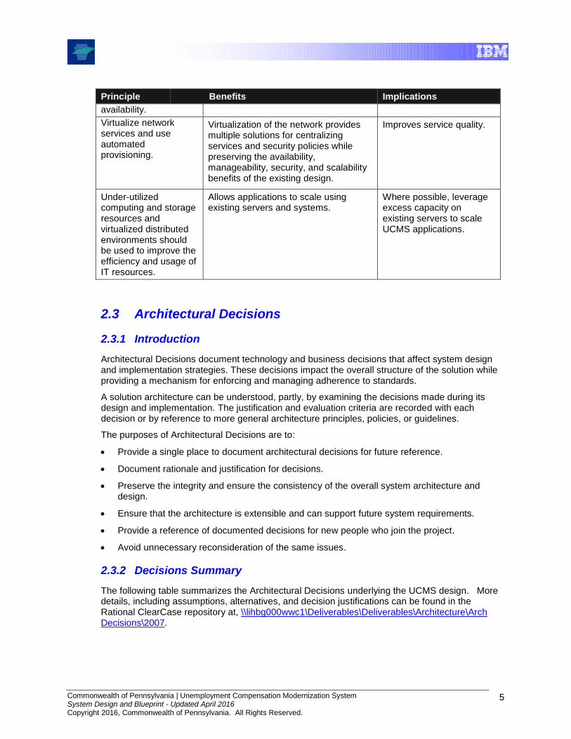
availability.
Virtualize network services and use automated provisioning.
Virtualization of the network provides multiple solutions for centralizing services and security policies while preserving the availability, manageability, security, and scalability benefits of the existing design.
Improves service quality.
Under-utilized computing and storage resources and virtualized distributed environments should be used to improve the efficiency and usage of IT resources.
Allows applications to scale using existing servers and systems.
Where possible, leverage excess capacity on existing servers to scale UCMS applications.
2.3 Architectural Decisions
2.3.1 Introduction
Architectural Decisions document technology and business decisions that affect system design and implementation strategies. These decisions impact the overall structure of the solution while providing a mechanism for enforcing and managing adherence to standards.
A solution architecture can be understood, partly, by examining the decisions made during its design and implementation. The justification and evaluation criteria are recorded with each decision or by reference to more general architecture principles, policies, or guidelines.
The purposes of Architectural Decisions are to:
Provide a single place to document architectural decisions for future reference.
Document rationale and justification for decisions.
Preserve the integrity and ensure the consistency of the overall system architecture and design.
Ensure that the architecture is extensible and can support future system requirements.
Provide a reference of documented decisions for new people who join the project.
Avoid unnecessary reconsideration of the same issues.
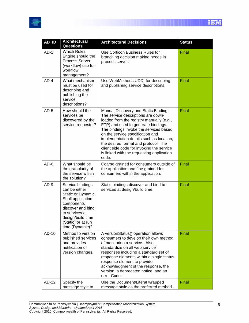
2.3.2 Decisions Summary
The following table summarizes the Architectural Decisions underlying the UCMS design. More details, including assumptions, alternatives, and decision justifications can be found in the Rational ClearCase repository at, \\lihbg000wwc1\Deliverables\Deliverables\Architecture\Arch Decisions\2007.
Commonwealth of Pennsylvania | Unemployment Compensation Modernization System System Design and Blueprint - Updated April 2016 Copyright 2016, Commonwealth of Pennsylvania. All Rights Reserved.
6
AD_ID Architectural Questions
Architectural Decisions Status
AD-1 Which Rules Engine should the Process Server (workflow) use for workflow management?
Use Corticon Business Rules for branching decision making needs in process server.
Final
AD-4 What mechanism must be used for describing and publishing the service descriptions?
Use WebMethods UDDI for describing and publishing service descriptions.
Final
AD-5 How should the services be discovered by the service requestor?
Manual Discovery and Static Binding: The service descriptions are down-loaded from the registry manually (e.g., FTP) and used to generate bindings. The bindings invoke the services based on the service specification and implementation details such as location, the desired format and protocol. The client side code for invoking the service is linked with the requesting application code.
Final
AD-6 What should be the granularity of the service within the solution?
Coarse grained for consumers outside of the application and fine grained for consumers within the application.
Final
AD-9 Service bindings can be either Static or Dynamic. Shall application components discover and bind to services at design/build time (Static) or at run time (Dynamic)?
Static bindings discover and bind to services at design/build time.
Final
AD-10 Method to version published services and provides notification of version changes.
A versionStatus() operation allows consumers to develop their own method of monitoring a service. Also, standardize on all web service responses including a standard set of response elements within a single status response element to provide acknowledgment of the response, the version, a deprecated notice, and an error Code.
Final
AD-12 Specify the message style to
Use the Document/Literal wrapped message style as the preferred method.
Final
Commonwealth of Pennsylvania | Unemployment Compensation Modernization System System Design and Blueprint - Updated April 2016 Copyright 2016, Commonwealth of Pennsylvania. All Rights Reserved.
7
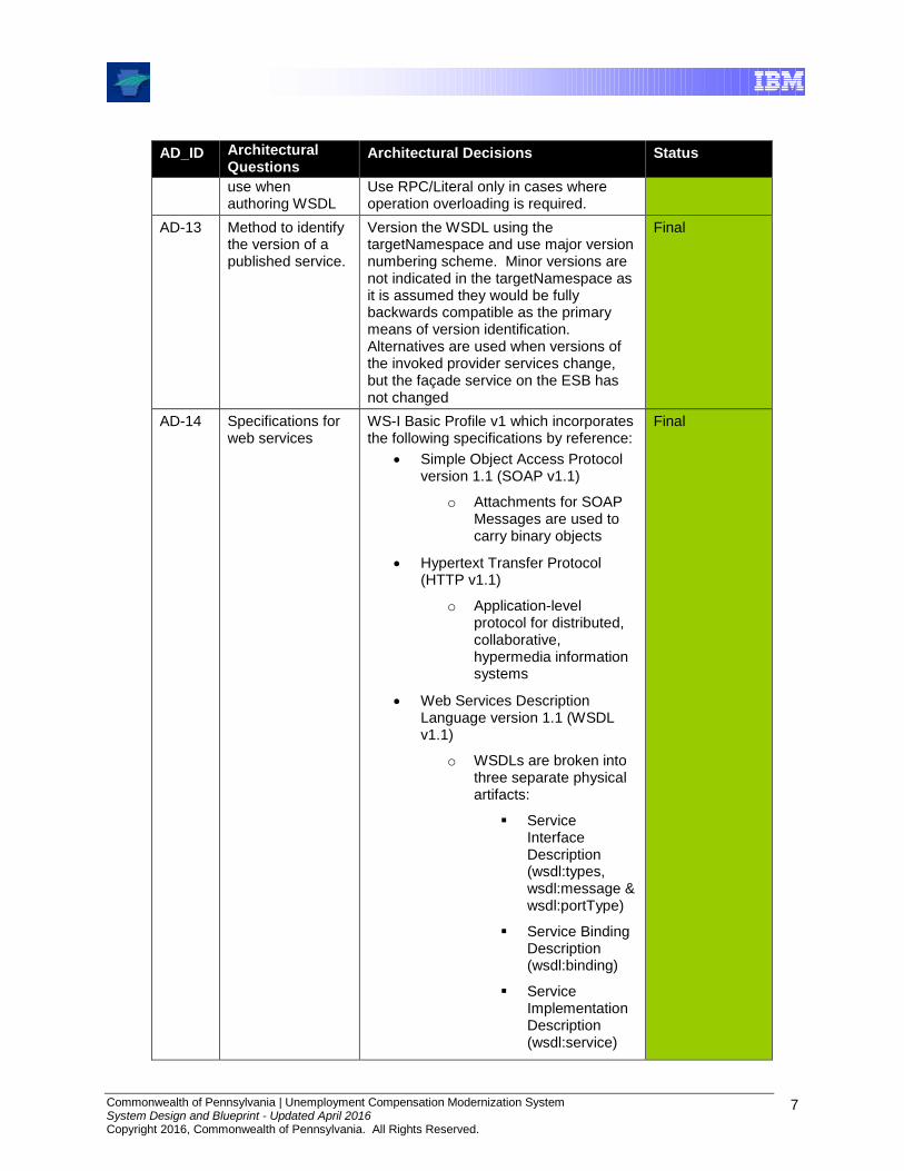
AD_ID Architectural Questions
Architectural Decisions Status
use when authoring WSDL
Use RPC/Literal only in cases where operation overloading is required.
AD-13 Method to identify the version of a published service.
Version the WSDL using the targetNamespace and use major version numbering scheme. Minor versions are not indicated in the targetNamespace as it is assumed they would be fully backwards compatible as the primary means of version identification. Alternatives are used when versions of the invoked provider services change, but the façade service on the ESB has not changed
Final
AD-14 Specifications for web services
WS-I Basic Profile v1 which incorporates the following specifications by reference:
Simple Object Access Protocol version 1.1 (SOAP v1.1)
o Attachments for SOAP Messages are used to carry binary objects
Hypertext Transfer Protocol (HTTP v1.1)
o Application-level protocol for distributed, collaborative, hypermedia information systems
Web Services Description Language version 1.1 (WSDL v1.1)
o WSDLs are broken into three separate physical artifacts:
Service Interface Description (wsdl:types, wsdl:message & wsdl:portType)
Service Binding Description (wsdl:binding)
Service Implementation Description (wsdl:service)
Final

Commonwealth of Pennsylvania | Unemployment Compensation Modernization System System Design and Blueprint - Updated April 2016 Copyright 2016, Commonwealth of Pennsylvania. All Rights Reserved.
8
AD_ID Architectural Questions
Architectural Decisions Status
o Uses flat data type definitions to avoid interoperability issues
o Reuses existing WSDL/XML vocabularies ranging from data type definitions to complete service definitions
Universal Description , Discovery and Integration version 2.0 (UDDI v2.0)
o Both a Production and Development UDDI Registry are used
eXtensible Markup Language version 1.0 (XML v1.0)
XML Schema
http://www.ws-i.org/deliverables/workinggroup.aspx?wg=basicprofile
AD-20 What mechanism will be used to expose services and to interconnect with external partners?
External partners could connect to the ESB via webMethods Trading Networks Server using HTTP/S, FTP/S, or SMTP protocols. Based on their business documents (XML, EDI) exchange, appropriate Processing Rules in the Trading Networks Server would be set up to handle the request and deliver the documents in return. The Processing rules would be responsible for invoking services/calls to DLI Enterprise Systems and UCMS.
Recommended, but not implemented
AD-23 What mechanism will be used to implement the communication interaction between the service requestor and the service provider?
Web services use HTTP for synchronous communications.
Web services use JMS for asynchronous communications.
Service Provider Interfaces and protocols are used for Non Web services on an as-needed basis.
Final
AD-25 Will the JSR-168 specification or vendor API’s be used to implement UCMS Portlets?
All UCMS portlets will conform to JSR-168 specifications. Vendor-specific API features will not be used.
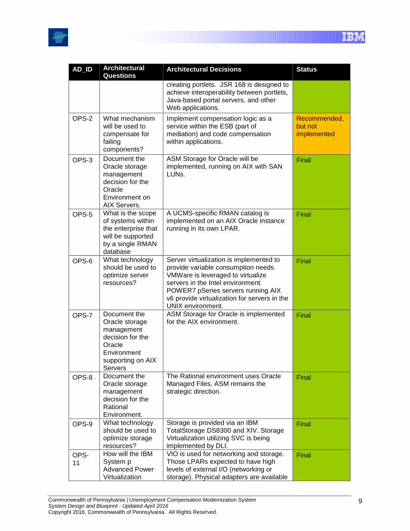
JSR 168 is a Java Specification Request that establishes a standard API for
Final
Commonwealth of Pennsylvania | Unemployment Compensation Modernization System System Design and Blueprint - Updated April 2016 Copyright 2016, Commonwealth of Pennsylvania. All Rights Reserved.
9
AD_ID Architectural Questions
Architectural Decisions Status
creating portlets. JSR 168 is designed to achieve interoperability between portlets, Java-based portal servers, and other Web applications.
OPS-2 What mechanism will be used to compensate for failing components?
Implement compensation logic as a service within the ESB (part of mediation) and code compensation within applications.
Recommended, but not implemented
OPS-3 Document the Oracle storage management decision for the Oracle Environment on AIX Servers.
ASM Storage for Oracle will be implemented, running on AIX with SAN LUNs.
Final
OPS-5 What is the scope of systems within the enterprise that will be supported by a single RMAN database
A UCMS-specific RMAN catalog is implemented on an AIX Oracle instance running in its own LPAR.
Final
OPS-6 What technology should be used to optimize server resources?
Server virtualization is implemented to provide variable consumption needs. VMWare is leveraged to virtualize servers in the Intel environment. POWER7 pSeries servers running AIX v6 provide virtualization for servers in the UNIX environment.
Final
OPS-7 Document the Oracle storage management decision for the Oracle Environment supporting on AIX Servers
ASM Storage for Oracle is implemented for the AIX environment.
Final
OPS-8 Document the Oracle storage management decision for the Rational Environment.
The Rational environment uses Oracle Managed Files. ASM remains the strategic direction.
Final
OPS-9 What technology should be used to optimize storage resources?
Storage is provided via an IBM TotalStorage DS8300 and XIV. Storage Virtualization utilizing SVC is being implemented by DLI.
Final
OPS-11
How will the IBM System p Advanced Power Virtualization
VIO is used for networking and storage. Those LPARs expected to have high levels of external I/O (networking or storage). Physical adapters are available
Final
Commonwealth of Pennsylvania | Unemployment Compensation Modernization System System Design and Blueprint - Updated April 2016 Copyright 2016, Commonwealth of Pennsylvania. All Rights Reserved.
10
AD_ID Architectural Questions
Architectural Decisions Status
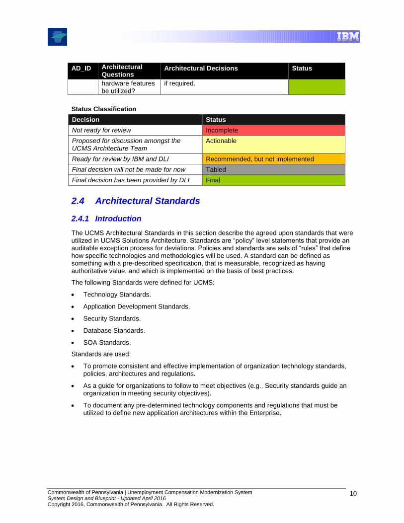
hardware features be utilized?
if required.
Status Classification
Decision Status
Not ready for review Incomplete
Proposed for discussion amongst the UCMS Architecture Team
Actionable
Ready for review by IBM and DLI Recommended, but not implemented
Final decision will not be made for now Tabled
Final decision has been provided by DLI Final
2.4 Architectural Standards
2.4.1 Introduction
The UCMS Architectural Standards in this section describe the agreed upon standards that were utilized in UCMS Solutions Architecture. Standards are “policy” level statements that provide an auditable exception process for deviations. Policies and standards are sets of “rules” that define how specific technologies and methodologies will be used. A standard can be defined as something with a pre-described specification, that is measurable, recognized as having authoritative value, and which is implemented on the basis of best practices.
The following Standards were defined for UCMS:
Technology Standards.
Application Development Standards.
Security Standards.
Database Standards.
SOA Standards.
Standards are used:
To promote consistent and effective implementation of organization technology standards, policies, architectures and regulations.
As a guide for organizations to follow to meet objectives (e.g., Security standards guide an organization in meeting security objectives).
To document any pre-determined technology components and regulations that must be utilized to define new application architectures within the Enterprise.
Commonwealth of Pennsylvania | Unemployment Compensation Modernization System System Design and Blueprint - Updated April 2016 Copyright 2016, Commonwealth of Pennsylvania. All Rights Reserved.
11
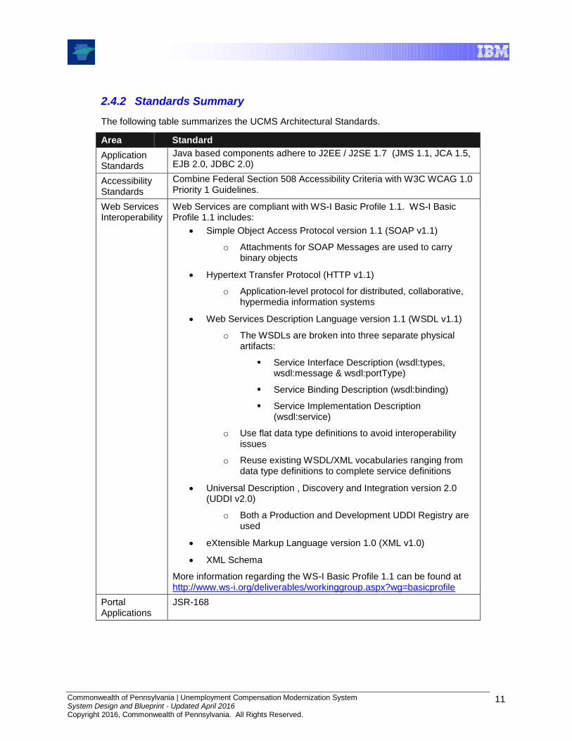
2.4.2 Standards Summary
The following table summarizes the UCMS Architectural Standards.
Area Standard
Application Standards
Java based components adhere to J2EE / J2SE 1.7 (JMS 1.1, JCA 1.5, EJB 2.0, JDBC 2.0)
Accessibility Standards
Combine Federal Section 508 Accessibility Criteria with W3C WCAG 1.0 Priority 1 Guidelines.
Web Services Interoperability
Web Services are compliant with WS-I Basic Profile 1.1. WS-I Basic Profile 1.1 includes:
Simple Object Access Protocol version 1.1 (SOAP v1.1)
o Attachments for SOAP Messages are used to carry binary objects
Hypertext Transfer Protocol (HTTP v1.1)
o Application-level protocol for distributed, collaborative, hypermedia information systems
Web Services Description Language version 1.1 (WSDL v1.1)
o The WSDLs are broken into three separate physical artifacts:
Service Interface Description (wsdl:types, wsdl:message & wsdl:portType)
Service Binding Description (wsdl:binding)
Service Implementation Description (wsdl:service)
o Use flat data type definitions to avoid interoperability issues
o Reuse existing WSDL/XML vocabularies ranging from data type definitions to complete service definitions
Universal Description , Discovery and Integration version 2.0 (UDDI v2.0)
o Both a Production and Development UDDI Registry are used
eXtensible Markup Language version 1.0 (XML v1.0)
XML Schema
More information regarding the WS-I Basic Profile 1.1 can be found at http://www.ws-i.org/deliverables/workinggroup.aspx?wg=basicprofile
Portal Applications
JSR-168
Commonwealth of Pennsylvania | Unemployment Compensation Modernization System System Design and Blueprint - Updated April 2016 Copyright 2016, Commonwealth of Pennsylvania. All Rights Reserved.
12
3.0 Solution Overview
3.1 Introduction
This section provides the overview of the solution by first introducing the UCMS System Context Diagram. The System Context clarifies and confirms the operating environment for the system by listing the entities external to UCMS that interact with UCMS. Following the system context is an overview of service-oriented architecture (SOA), the pieces of a SOA infrastructure and how it is utilized for UCMS.
3.2 System Context
3.2.1 Introduction
The System Context represents the entire system as a single object or process and identifies the interfaces between the system and external entities. Usually shown as a diagram, this representation defines the system and identifies the information and control flows that cross the system boundary. For UCMS, the Wage and Tax Context diagram (in a later section) should be used for as-is context information.
The System Context highlights several important characteristics of the system: users, external systems, batch inputs and outputs, and external devices. It also depicts:
External events to which the system must or should respond.
Events that the system generates that may affect external entities.
Data that the system receives from the outside world that should be processed in some way.
Data produced by the system and sent to the outside world.
Objects within the system boundary define the scope over which the development team has some control. Usually, the users and systems represented in the system context diagram are outside the boundary of the system and affect the system operation and development but are beyond the control of the developers within the currently defined scope of the project. However, for the sake of completeness, the following entities are called-out in the system context diagram:
Field Auditors – The tax field audit application has not been used as part of UCMS but is included in the UCMS code base.
The purpose of the System Context is:
To clarify and confirm the environment in which the system has to operate.
To provide the details at an adequate level to allow the creation of the relevant technical specification(s).
The UCMS System Context Diagram is shown on the next page, followed by descriptions of the external entities with which UCMS interacts
.

Commonwealth of Pennsylvania | Unemployment Compensation Modernization System System Design and Blueprint - Updated April 2016 Copyright 2016, Commonwealth of Pennsylvania. All Rights Reserved.
13
3.2.2 System Context Diagram
Figure 3.2-1: UCMS System Context Diagram
Commonwealth of Pennsylvania | Unemployment Compensation Modernization System System Design and Blueprint - Updated April 2016 Copyright 2016, Commonwealth of Pennsylvania. All Rights Reserved.
14
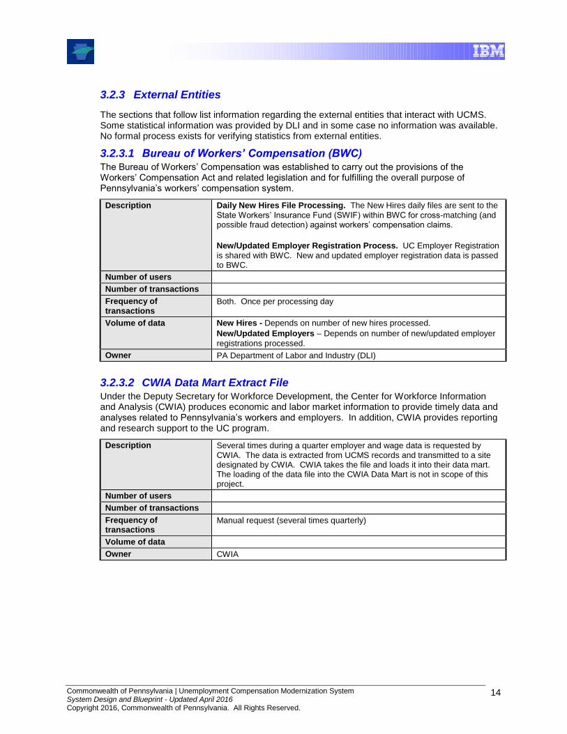
3.2.3 External Entities
The sections that follow list information regarding the external entities that interact with UCMS. Some statistical information was provided by DLI and in some case no information was available. No formal process exists for verifying statistics from external entities.
3.2.3.1 Bureau of Workers’ Compensation (BWC) The Bureau of Workers’ Compensation was established to carry out the provisions of the Workers’ Compensation Act and related legislation and for fulfilling the overall purpose of Pennsylvania’s workers’ compensation system.
Description Daily New Hires File Processing. The New Hires daily files are sent to the
State Workers’ Insurance Fund (SWIF) within BWC for cross-matching (and possible fraud detection) against workers’ compensation claims.
New/Updated Employer Registration Process. UC Employer Registration
is shared with BWC. New and updated employer registration data is passed to BWC.
Number of users
Number of transactions
Frequency of transactions
Both. Once per processing day
Volume of data New Hires - Depends on number of new hires processed.
New/Updated Employers – Depends on number of new/updated employer
registrations processed.
Owner PA Department of Labor and Industry (DLI)
3.2.3.2 CWIA Data Mart Extract File Under the Deputy Secretary for Workforce Development, the Center for Workforce Information and Analysis (CWIA) produces economic and labor market information to provide timely data and analyses related to Pennsylvania’s workers and employers. In addition, CWIA provides reporting and research support to the UC program.
Description Several times during a quarter employer and wage data is requested by CWIA. The data is extracted from UCMS records and transmitted to a site designated by CWIA. CWIA takes the file and loads it into their data mart. The loading of the data file into the CWIA Data Mart is not in scope of this project.
Number of users
Number of transactions
Frequency of transactions
Manual request (several times quarterly)
Volume of data
Owner CWIA
Commonwealth of Pennsylvania | Unemployment Compensation Modernization System System Design and Blueprint - Updated April 2016 Copyright 2016, Commonwealth of Pennsylvania. All Rights Reserved.
15
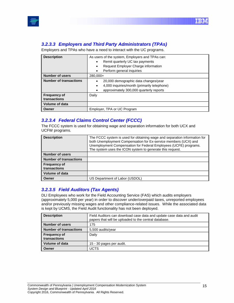
3.2.3.3 Employers and Third Party Administrators (TPAs) Employers and TPAs who have a need to interact with the UC programs.
Description As users of the system, Employers and TPAs can:
Remit quarterly UC tax payments
Request Employer Charge information
Perform general inquiries
Number of users 280,000+
Number of transactions 20,000 demographic data changes/year
4,000 inquiries/month (primarily telephone)
approximately 300,000 quarterly reports
Frequency of transactions
Daily
Volume of data
Owner Employer, TPA or UC Program
3.2.3.4 Federal Claims Control Center (FCCC) The FCCC system is used for obtaining wage and separation information for both UCX and UCFW programs.
Description The FCCC system is used for obtaining wage and separation information for both Unemployment Compensation for Ex-service members (UCX) and Unemployment Compensation for Federal Employees (UCFE) programs. The system uses the ICON system to generate this request.
Number of users
Number of transactions
Frequency of transactions
Volume of data
Owner US Department of Labor (USDOL)
3.2.3.5 Field Auditors (Tax Agents) DLI Employees who work for the Field Accounting Service (FAS) which audits employers (approximately 5,000 per year) in order to discover under/overpaid taxes, unreported employees and/or previously missing wages and other compliance-related issues. While the associated data is kept by UCMS, the Field Audit functionality has not been deployed.
Description Field Auditors can download case data and update case data and audit papers that will be uploaded to the central database.
Number of users 175
Number of transactions 5,500 audits/year
Frequency of transactions
Daily
Volume of data 15 - 30 pages per audit.
Owner UCTS
Commonwealth of Pennsylvania | Unemployment Compensation Modernization System System Design and Blueprint - Updated April 2016 Copyright 2016, Commonwealth of Pennsylvania. All Rights Reserved.
16
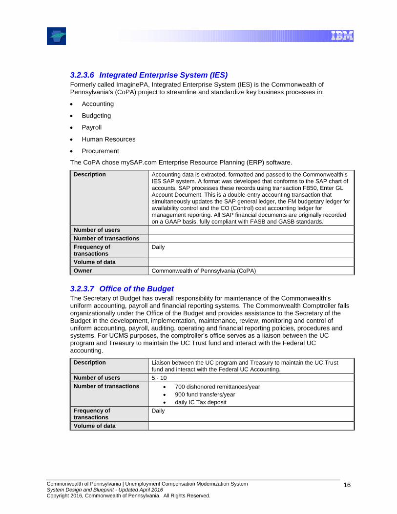
3.2.3.6 Integrated Enterprise System (IES) Formerly called ImaginePA, Integrated Enterprise System (IES) is the Commonwealth of Pennsylvania's (CoPA) project to streamline and standardize key business processes in:
Accounting
Budgeting
Payroll
Human Resources
Procurement
The CoPA chose mySAP.com Enterprise Resource Planning (ERP) software.
Description Accounting data is extracted, formatted and passed to the Commonwealth’s IES SAP system. A format was developed that conforms to the SAP chart of accounts. SAP processes these records using transaction FB50, Enter GL Account Document. This is a double-entry accounting transaction that simultaneously updates the SAP general ledger, the FM budgetary ledger for availability control and the CO (Control) cost accounting ledger for management reporting. All SAP financial documents are originally recorded on a GAAP basis, fully compliant with FASB and GASB standards.
Number of users
Number of transactions
Frequency of transactions
Daily
Volume of data
Owner Commonwealth of Pennsylvania (CoPA)
3.2.3.7 Office of the Budget The Secretary of Budget has overall responsibility for maintenance of the Commonwealth's uniform accounting, payroll and financial reporting systems. The Commonwealth Comptroller falls organizationally under the Office of the Budget and provides assistance to the Secretary of the Budget in the development, implementation, maintenance, review, monitoring and control of uniform accounting, payroll, auditing, operating and financial reporting policies, procedures and systems. For UCMS purposes, the comptroller’s office serves as a liaison between the UC program and Treasury to maintain the UC Trust fund and interact with the Federal UC accounting.
Description Liaison between the UC program and Treasury to maintain the UC Trust fund and interact with the Federal UC Accounting.
Number of users 5 - 10
Number of transactions 700 dishonored remittances/year
900 fund transfers/year
daily IC Tax deposit
Frequency of transactions
Daily
Volume of data
Commonwealth of Pennsylvania | Unemployment Compensation Modernization System System Design and Blueprint - Updated April 2016 Copyright 2016, Commonwealth of Pennsylvania. All Rights Reserved.
17
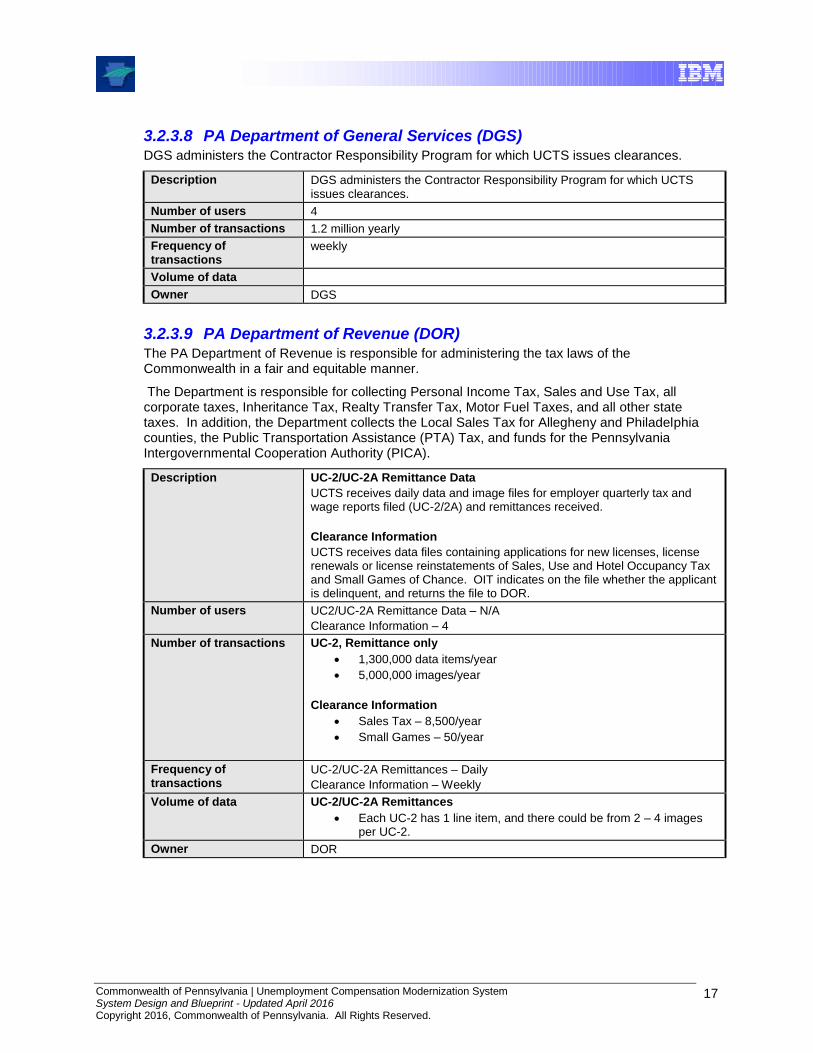
3.2.3.8 PA Department of General Services (DGS) DGS administers the Contractor Responsibility Program for which UCTS issues clearances.
Description DGS administers the Contractor Responsibility Program for which UCTS issues clearances.
Number of users 4
Number of transactions 1.2 million yearly
Frequency of transactions
weekly
Volume of data
Owner DGS
3.2.3.9 PA Department of Revenue (DOR)
The PA Department of Revenue is responsible for administering the tax laws of the Commonwealth in a fair and equitable manner.
The Department is responsible for collecting Personal Income Tax, Sales and Use Tax, all corporate taxes, Inheritance Tax, Realty Transfer Tax, Motor Fuel Taxes, and all other state taxes. In addition, the Department collects the Local Sales Tax for Allegheny and Philadelphia counties, the Public Transportation Assistance (PTA) Tax, and funds for the Pennsylvania Intergovernmental Cooperation Authority (PICA).
Description UC-2/UC-2A Remittance Data
UCTS receives daily data and image files for employer quarterly tax and wage reports filed (UC-2/2A) and remittances received.
Clearance Information
UCTS receives data files containing applications for new licenses, license renewals or license reinstatements of Sales, Use and Hotel Occupancy Tax and Small Games of Chance. OIT indicates on the file whether the applicant is delinquent, and returns the file to DOR.
Number of users UC2/UC-2A Remittance Data – N/A
Clearance Information – 4
Number of transactions UC-2, Remittance only
1,300,000 data items/year
5,000,000 images/year
Clearance Information
Sales Tax – 8,500/year
Small Games – 50/year
Frequency of transactions
UC-2/UC-2A Remittances – Daily
Clearance Information – Weekly
Volume of data UC-2/UC-2A Remittances
Each UC-2 has 1 line item, and there could be from 2 – 4 images per UC-2.
Owner DOR

Commonwealth of Pennsylvania | Unemployment Compensation Modernization System System Design and Blueprint - Updated April 2016 Copyright 2016, Commonwealth of Pennsylvania. All Rights Reserved.
18
3.2.3.10 PA Department of Treasury The Treasury Department is responsible for accounting for financial transactions between the departments and other external parties, including the federal government and financial institutions. The process for making payments begins with individual state agencies preparing requisitions that are submitted to Treasury. These requisitions are then audited by the Treasury Department in accordance with generally accepted auditing standards.
Additionally, for UCTS purposes, Treasury is responsible for the safe keeping of collateral instruments. They also control and perform the accounting for commonwealth issued checks, including preparation of UC tax refund checks.
Description 1. Daily and quarterly transmission of UC Tax refunds to employers.
2. UC Disbursements:
Daily transmission of all check records for UC, TEUC, TRA, DUA.
Daily FTP of UC Claimant’s Direct Deposit UC check data to Treasury’s Oracle database.
Daily transmission of total amount of funds to be allocated to Child Support.
Number of users 5
Number of transactions 19,000 tax refunds/year
Frequency of transactions
Daily, Quarterly
Volume of data
Owner PA Department of Treasury
3.2.3.11 PA Liquor Control Board (PLCB) The LCB issues liquor licenses and renewals for which UCTS issues clearances.
Description The PLCB issues liquor licenses and renewals for which UCTS issues clearances.
Number of users 4
Number of transactions 21,000 per year
Frequency of transactions
Weekly
Volume of data
Owner PLCB

Commonwealth of Pennsylvania | Unemployment Compensation Modernization System System Design and Blueprint - Updated April 2016 Copyright 2016, Commonwealth of Pennsylvania. All Rights Reserved.
19
3.2.3.12 PNC Bank PNC Bank is a subsidiary of PNC Financial Services Group, Inc. PNC Financial Services Group, Inc. is a U.S. based financial services corporation, with operations including a regional banking franchise operating primarily in eight states and the District of Columbia, specialized financial businesses serving companies, government entities, and leading asset management and processing businesses.
Description Each day a file is sent to PNC Bank via FTP that contains electronic banking information such as prenotes and ACH credits. In return, PNC bank sends payments records that the bank processed that day.
Number of users 4
Number of transactions Approx. 40,000/quarter
Frequency of transactions
Daily
Volume of data
Owner PNC Financial Services Group, Inc.
3.2.3.13 US Department of Labor (USDOL) The U.S. Department of Labor administers a variety of Federal labor laws including those that guarantee workers’ rights to safe and healthful working conditions; a minimum hourly wage and overtime pay; freedom from employment discrimination; unemployment insurance; and other income support.
Description DLI must meet all USDOL reporting requirements for Data Validation, UI Performs and workforce measurements.
Number of users 5
Number of transactions
Frequency of transactions
Yearly, Monthly, Quarterly and On Demand
Volume of data
Owner USDOL
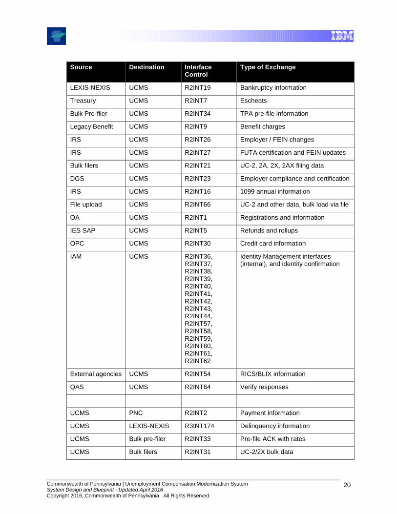
3.2.4 Interface Summary
The interfaces shown in the System Context diagram are summarized in the following table. For specific details on any of the interfaces, refer to the Interface Control Document(s) for that system or interface.
Source Destination Interface Control
Type of Exchange
DOR UCMS R2INT10 Scanned checks and vouchers
DOR UCMS R2INT25 List of payments received
DOR UCMS R3INT227 Correspondence
OPC UCMS R2INT22 Credit Card payment info
PNC UCMS R2INT3 ACH Debits and Credits
PNC UCMS R2INT24 Rejected employer info
Commonwealth of Pennsylvania | Unemployment Compensation Modernization System System Design and Blueprint - Updated April 2016 Copyright 2016, Commonwealth of Pennsylvania. All Rights Reserved.
20
Source Destination Interface Control
Type of Exchange
LEXIS-NEXIS UCMS R2INT19 Bankruptcy information
Treasury UCMS R2INT7 Escheats
Bulk Pre-filer UCMS R2INT34 TPA pre-file information
Legacy Benefit UCMS R2INT9 Benefit charges
IRS UCMS R2INT26 Employer / FEIN changes
IRS UCMS R2INT27 FUTA certification and FEIN updates
Bulk filers UCMS R2INT21 UC-2, 2A, 2X, 2AX filing data
DGS UCMS R2INT23 Employer compliance and certification
IRS UCMS R2INT16 1099 annual information
File upload UCMS R2INT66 UC-2 and other data, bulk load via file
OA UCMS R2INT1 Registrations and information
IES SAP UCMS R2INT5 Refunds and rollups
OPC UCMS R2INT30 Credit card information
IAM UCMS R2INT36, R2INT37, R2INT38, R2INT39, R2INT40, R2INT41, R2INT42, R2INT43, R2INT44, R2INT57, R2INT58, R2INT59, R2INT60, R2INT61, R2INT62
Identity Management interfaces (internal), and identity confirmation
External agencies UCMS R2INT54 RICS/BLIX information
QAS UCMS R2INT64 Verify responses
UCMS PNC R2INT2 Payment information
UCMS LEXIS-NEXIS R3INT174 Delinquency information
UCMS Bulk pre-filer R2INT33 Pre-file ACK with rates
UCMS Bulk filers R2INT31 UC-2/2X bulk data
Commonwealth of Pennsylvania | Unemployment Compensation Modernization System System Design and Blueprint - Updated April 2016 Copyright 2016, Commonwealth of Pennsylvania. All Rights Reserved.
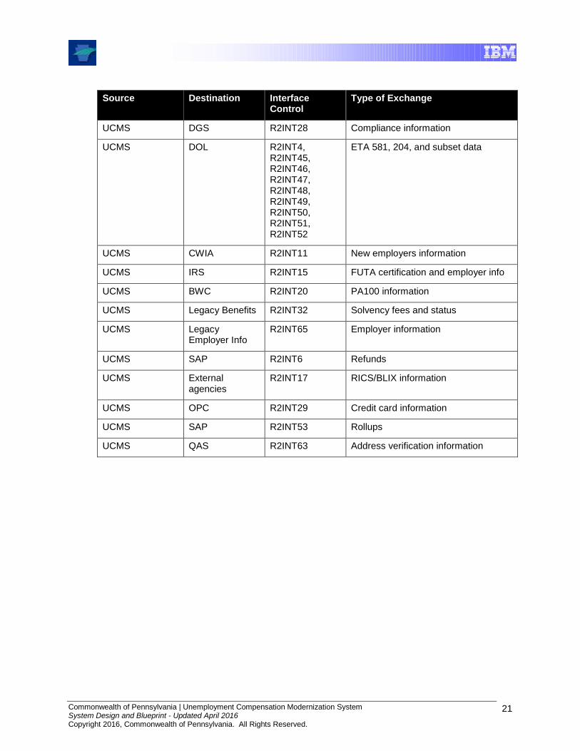
21
Source Destination Interface Control
Type of Exchange
UCMS DGS R2INT28 Compliance information
UCMS DOL R2INT4, R2INT45, R2INT46, R2INT47, R2INT48, R2INT49, R2INT50, R2INT51, R2INT52
ETA 581, 204, and subset data
UCMS CWIA R2INT11 New employers information
UCMS IRS R2INT15 FUTA certification and employer info
UCMS BWC R2INT20 PA100 information
UCMS Legacy Benefits R2INT32 Solvency fees and status
UCMS Legacy Employer Info
R2INT65 Employer information
UCMS SAP R2INT6 Refunds
UCMS External agencies
R2INT17 RICS/BLIX information
UCMS OPC R2INT29 Credit card information
UCMS SAP R2INT53 Rollups
UCMS QAS R2INT63 Address verification information

Commonwealth of Pennsylvania | Unemployment Compensation Modernization System System Design and Blueprint - Updated April 2016 Copyright 2016, Commonwealth of Pennsylvania. All Rights Reserved.
22
3.3 Service-Oriented Architecture
3.3.1 Introduction
The primary goal of Service Oriented Architecture (SOA) is to align the business world with the world of information technology (IT) in a way that makes both more effective. SOA is a bridge that creates a synergistic relationship between the two that is more powerful and valuable than anything experienced in the past. Moreover, SOA is focused on the business results that can be achieved from having better alignment between the business and IT.
SOA starts from the premise that all businesses have a business design – the processes it performs, the organizational structure of its people and finances, its near- and long-term goals and objectives, the rules and policies that condition how it operates. The key idea extending from this is that, if the business design can be directly transcribed and implemented in a highly adaptable and dynamic way, there is then tremendous potential to drive changes into the information system at the rate and pace of change in the business design.
This thinking is not new, but the capability to actually implement it is new. It required the arrival of several enabling technologies, including Web services, Business Process Execution Language (BPEL), and the enterprise service bus (ESB).
In this section, SOA is made more tangible by looking at how it is done in a logical sense, via the SOA layers model, and by quantifying the services in SOA. An example using a UCMS-specific scenario is employed to illustrate the usage of the SOA Layers and services. Then, how a set of SOA-based common services, also known as the UCMS Common Modules, serves as the foundation for all other releases are discussed. Lastly, the implementation of the IBM SOA Reference Architecture for UCMS is described.
3.3.2 SOA Layered Model
From a technical standpoint, Service-Oriented Architecture is an architectural style for creating an Enterprise IT Architecture that exploits the principles of service orientation to achieve a tighter relationship between the business and the information systems that support the business.
At its simplest, it can be said that a SOA must contain three key elements. The following figure illustrates a basic SOA model and the set of key elements that are required for this design style.
Service
Requestor
Service
Provider
Service
Registry
(UDDI)
FindPublish
Bind
Service
Requestor
Service
Provider
Service
Registry
(UDDI)
FindPublish
Bind
Figure 3.3-1: Basic SOA Model
Commonwealth of Pennsylvania | Unemployment Compensation Modernization System System Design and Blueprint - Updated April 2016 Copyright 2016, Commonwealth of Pennsylvania. All Rights Reserved.
23
The service providers are systems that offer a computing function that is made available to service requestors. The common way a provider’s service is made available is through a service registry. The process of making the service available to the service registry is called publishing. The registry is typically some form of a repository that contains a listing of all of the services available and the necessary information to invoke the service. The repository usually contains a service description or some metadata about the service. The service description provides the necessary information for invoking the service and any other conditions for its use (API’s, message structures, interface definitions, qualities of service, etc).
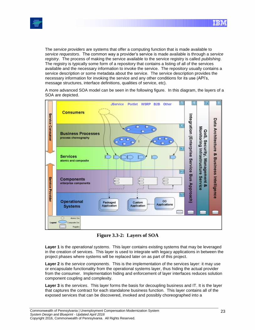
A more advanced SOA model can be seen in the following figure. In this diagram, the layers of a SOA are depicted.
Figure 3.3-2: Layers of SOA
Layer 1 is the operational systems. This layer contains existing systems that may be leveraged in the creation of services. This layer is used to integrate with legacy applications in between the project phases where systems will be replaced later on as part of this project.
Layer 2 is the service components. This is the implementation of the services layer: it may use or encapsulate functionality from the operational systems layer, thus hiding the actual provider from the consumer. Implementation hiding and enforcement of layer interfaces reduces solution component coupling and complexity.
Layer 3 is the services. This layer forms the basis for decoupling business and IT. It is the layer that captures the contract for each standalone business function. This layer contains all of the exposed services that can be discovered, invoked and possibly choreographed into a

Commonwealth of Pennsylvania | Unemployment Compensation Modernization System System Design and Blueprint - Updated April 2016 Copyright 2016, Commonwealth of Pennsylvania. All Rights Reserved.
24
composition. Each service is a contract between service consumers and service providers. It represents a governed business operation that is potentially consumed by multiple business processes and/or consumers. Services may be “atomic” (self-contained) or “composite” (i.e., made up of other atomic and/or composite services).
Layer 4 is the business processes. This layer contains the operational artifacts that implement business processes as a choreography of services. The set of services that are choreographed is limited to services offered in Layer 3.
Layer 5 is the consumers (requestors). This layer exists to recognize that the technology chosen to implement business processes in Layer 4 must permit access from a wide set of channels.
Layer 6 is the integration or Enterprise Service Bus (ESB) layer. This is a cross cutting layer, meaning it is used across all of the first five layers. The ESB provides routing of services, protocol translation, message transformation and mediation.
Layer 7 is the Quality of Service layer. This layer is again cross cutting, its focus is on quality characteristics of a service invocation, securing services and providing management and monitoring of the infrastructure upon which the service-oriented architecture is deployed. This layer also provides logging and auditing functionalities.
Layer 8 is the Data and Business Intelligence layer. This layer is again cross cutting across the first five layers. It provides data access components to enable services to get at and manipulate business data.
3.3.3 UCMS SOA Illustration
To further illustrate the layers of service-oriented architecture and the implementation of services, it is appropriate to provide a UCMS example.
Figure 3.3-3: UCMS Illustration of SOA Layers

Commonwealth of Pennsylvania | Unemployment Compensation Modernization System System Design and Blueprint - Updated April 2016 Copyright 2016, Commonwealth of Pennsylvania. All Rights Reserved.
25
3.3.4 UCMS Common Modules
UCMS provides foundational business services that are reused and are often referred to as the Common Modules. They include: Case Management, Interested Party Management, Financial Management, and Appeals Management.
Each of these modules is defined using a Service Model. The service model lists the services needed to satisfy the functionality required for each module in a service portfolio. Each service in the portfolio is evaluated based on business needs to determine if the service is to be implemented. The service interface is then fully specified using WSDL – these are the services made available at Layer 3 of the SOA Layers.
Components provide the implementation(s) for the service specifications. The implementation of the components may be provided by the Application Services UCMS-Framework and are deployed at Layer 2 of the SOA Layers. Other components with functionality that is provided by another application or by a specific product are deployed at SOA Layer 1.
In the example above, the Interested Party Management module provides a collection of services that enable an application to interact with Interested Parties. Interested Parties may be workers, employers, owner-officers, third party administrators, or others. This module provides a service to manage the creation of these “Interested Parties”, it maintains the relationships between parties, associates documents and notes to parties, provides the searching functionality, and has the ability to update or modify the party. As usual, the available services are all specified using WSDL. The components that implement the services are created primarily with the Application Services UCMS-Framework with some functionality provided by specific products.
The Case Management module provides a collection of services that enable an application to interact with a Case. Cases are created for employers, and employer audits. An employer case manages information for liable employers. An employer audit case manages tax audit information for employer audits. The services provided enable applications to create, combine & uncombined cases, to associate documents and notes to cases, to create and update tasks, and to schedule and reschedule appointments. The services are all specified using WSDL. The components that implement the services are created primarily with the Application Services UCMS-Framework with some functionality provided by specific products.
The Financial Management module provides a collection of services to create or utilize financial transactions. Anywhere in a UC application where financial transactions are needed, this module provides the basic functionality to create the transaction in a uniform and standard way. The services provided enable applications to create financial transactions for receivables, write-offs, remittances, deductions, disbursements, and others. The services are all specified using WSDL. The components that implement the services are created primarily with the Application Services UCMS-Framework, with some functionality provided by specific products.
The Appeals Management module provides a collection of services that enable an application to manage appeals. Services are provided to enable applications to track appeals, accept different levels of appeals, generate subpoenas, assign referees to appeals, schedule hearings, remand cases, record appeal decisions and associate documents with the appeals. The services are all specified using WSDL. The components that implement the services are created primarily with the Application Services UCMS-Framework with some functionality provided by specific products.
3.3.5 Services in SOA
One of the most common debates in the discussion of SOA is over the question of “what is a service?” Is it a function within my application? Are all application functions services? Does SOA include system services? These are all relevant and important questions. Coming up with a
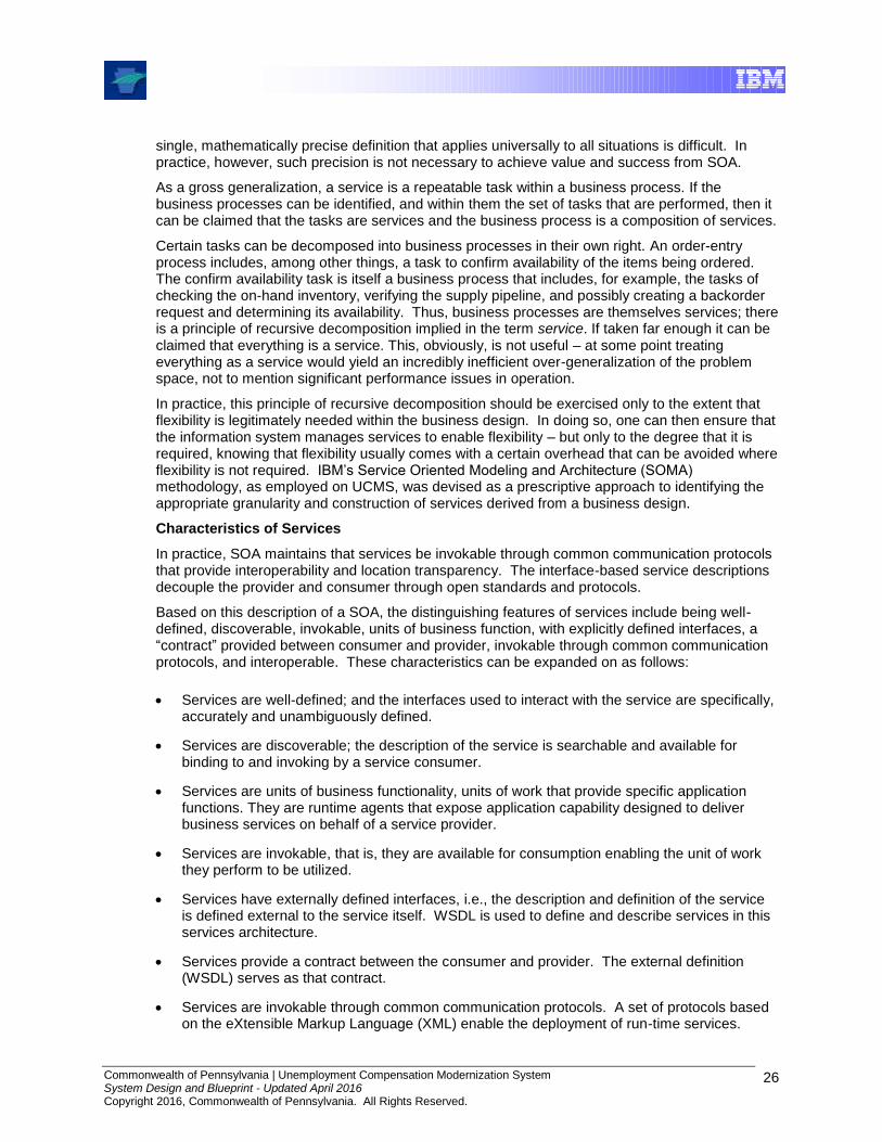
Commonwealth of Pennsylvania | Unemployment Compensation Modernization System System Design and Blueprint - Updated April 2016 Copyright 2016, Commonwealth of Pennsylvania. All Rights Reserved.
26
single, mathematically precise definition that applies universally to all situations is difficult. In practice, however, such precision is not necessary to achieve value and success from SOA.
As a gross generalization, a service is a repeatable task within a business process. If the business processes can be identified, and within them the set of tasks that are performed, then it can be claimed that the tasks are services and the business process is a composition of services.
Certain tasks can be decomposed into business processes in their own right. An order-entry process includes, among other things, a task to confirm availability of the items being ordered. The confirm availability task is itself a business process that includes, for example, the tasks of checking the on-hand inventory, verifying the supply pipeline, and possibly creating a backorder request and determining its availability. Thus, business processes are themselves services; there is a principle of recursive decomposition implied in the term service. If taken far enough it can be claimed that everything is a service. This, obviously, is not useful – at some point treating everything as a service would yield an incredibly inefficient over-generalization of the problem space, not to mention significant performance issues in operation.
In practice, this principle of recursive decomposition should be exercised only to the extent that flexibility is legitimately needed within the business design. In doing so, one can then ensure that the information system manages services to enable flexibility – but only to the degree that it is required, knowing that flexibility usually comes with a certain overhead that can be avoided where flexibility is not required. IBM’s Service Oriented Modeling and Architecture (SOMA) methodology, as employed on UCMS, was devised as a prescriptive approach to identifying the appropriate granularity and construction of services derived from a business design.
Characteristics of Services
In practice, SOA maintains that services be invokable through common communication protocols that provide interoperability and location transparency. The interface-based service descriptions decouple the provider and consumer through open standards and protocols.
Based on this description of a SOA, the distinguishing features of services include being well-defined, discoverable, invokable, units of business function, with explicitly defined interfaces, a “contract” provided between consumer and provider, invokable through common communication protocols, and interoperable. These characteristics can be expanded on as follows:
Services are well-defined; and the interfaces used to interact with the service are specifically, accurately and unambiguously defined.
Services are discoverable; the description of the service is searchable and available for binding to and invoking by a service consumer.
Services are units of business functionality, units of work that provide specific application functions. They are runtime agents that expose application capability designed to deliver business services on behalf of a service provider.
Services are invokable, that is, they are available for consumption enabling the unit of work they perform to be utilized.
Services have externally defined interfaces, i.e., the description and definition of the service is defined external to the service itself. WSDL is used to define and describe services in this services architecture.
Services provide a contract between the consumer and provider. The external definition (WSDL) serves as that contract.
Services are invokable through common communication protocols. A set of protocols based on the eXtensible Markup Language (XML) enable the deployment of run-time services.
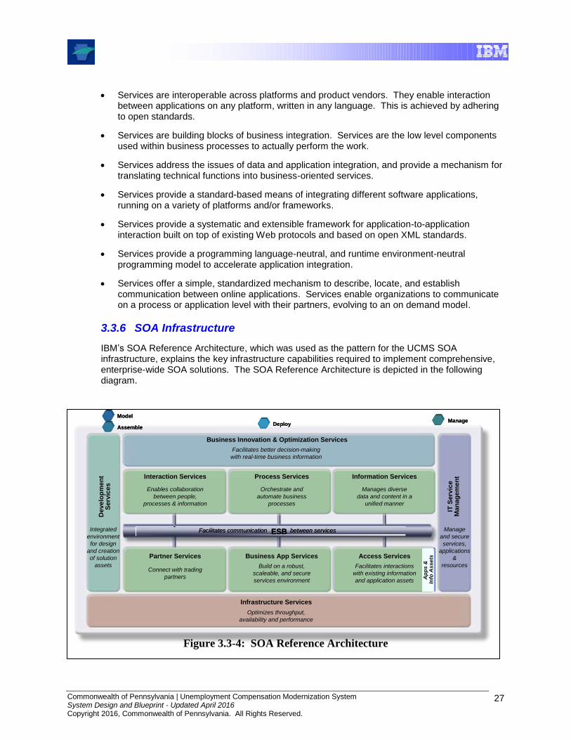
Commonwealth of Pennsylvania | Unemployment Compensation Modernization System System Design and Blueprint - Updated April 2016 Copyright 2016, Commonwealth of Pennsylvania. All Rights Reserved.
27
Services are interoperable across platforms and product vendors. They enable interaction between applications on any platform, written in any language. This is achieved by adhering to open standards.
Services are building blocks of business integration. Services are the low level components used within business processes to actually perform the work.
Services address the issues of data and application integration, and provide a mechanism for translating technical functions into business-oriented services.
Services provide a standard-based means of integrating different software applications, running on a variety of platforms and/or frameworks.
Services provide a systematic and extensible framework for application-to-application interaction built on top of existing Web protocols and based on open XML standards.
Services provide a programming language-neutral, and runtime environment-neutral programming model to accelerate application integration.
Services offer a simple, standardized mechanism to describe, locate, and establish communication between online applications. Services enable organizations to communicate on a process or application level with their partners, evolving to an on demand model.
3.3.6 SOA Infrastructure
IBM’s SOA Reference Architecture, which was used as the pattern for the UCMS SOA infrastructure, explains the key infrastructure capabilities required to implement comprehensive, enterprise-wide SOA solutions. The SOA Reference Architecture is depicted in the following diagram.
Figure 3.3-4: SOA Reference Architecture
Ap
ps
&
Info
Asse
tsA
pp
s &
In
fo A
sse
ts
Business Innovation & Optimization Services
De
velo
pm
en
tS
erv
ices
Interaction Services Process Services Information Services
Partner Services Business App Services Access Services
Integrated
environment
for design
and creation
of solution
assets
Manage
and secure
services,
applications
&
resources
Facilitates better decision-making
with real-time business information
Enables collaboration
between people,
processes & information
Orchestrate and
automate business
processes
Manages diverse
data and content in a
unified manner
Connect with trading
partners
Build on a robust,
scaleable, and secure
services environment
Facilitates interactions
with existing information
and application assets
ESBFacilitates communication between servicesESBFacilitates communication between services
IT S
erv
ice
Man
ag
em
en
t
Infrastructure Services
Optimizes throughput,
availability and performance
ModelModel
AssembleAssembleDeployDeploy
ManageManage

Commonwealth of Pennsylvania | Unemployment Compensation Modernization System System Design and Blueprint - Updated April 2016 Copyright 2016, Commonwealth of Pennsylvania. All Rights Reserved.
28
The SOA Reference Architecture includes Development Services for use in designing and creating the workflows, services and components in the SOA. It includes Business Innovation & Optimization Services (alternately referred to as Business Process Management) for use in monitoring and managing the runtime implementations at both the IT and business process levels. A key feature of the Architecture is a linkage between the Development and Business Innovation and Optimization Services (BIOS). The ability to deliver runtime data and statistics into the development environment allows analyses to be completed that drive iterative process re-engineering through a continuous business process improvement cycle.
The SOA Reference Architecture contains a set of services that are oriented toward the integration of people, processes, and information. These services include:
Interaction Services –capabilities required to deliver IT functions and data to end users.
Process Services – implement workflows and manage the interactions of multiple services in ways that implement business processes, i.e., “business choreography”.
Information Services – provide the capabilities required to federate, replicate, and transform data sources.
At the core of the SOA Reference Architecture is the Enterprise Service Bus. This architectural construct provides inter-connectivity to leverage and use services across the entire architecture. The ESB is a key factor in enabling the service-orientation of the architecture.
The Business Application Services provide runtime services required for new application components to be included in the integrated system. Design and implementation of new business logic components for integration enables them to be fully re-useable, allowing them to participate in new and updated business processes over time.
Existing enterprise applications and enterprise data are accessible through a set of Access Services. These provide the bridging capabilities between legacy applications, pre-packaged applications, enterprise data stores (including relational, hierarchical and nontraditional, unstructured sources such as XML and Text), etc. and the ESB. Using a consistent approach, these access services expose the data and functions of the existing enterprise applications, allowing them to be incorporated into functional flows that represent business processes.
Integrating the systems of external partners with those of the enterprise improves efficiency of the overall value chain. Partner Services provide the connectivity and integration services required for efficient implementation of business-to-business processes and interactions.
Underlying all these capabilities of the SOA Reference Architecture is a set of Infrastructure Services which provide security, directory, IT system management, and related functions.
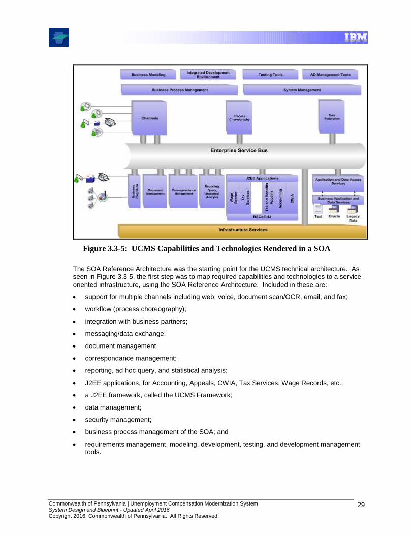
Commonwealth of Pennsylvania | Unemployment Compensation Modernization System System Design and Blueprint - Updated April 2016 Copyright 2016, Commonwealth of Pennsylvania. All Rights Reserved.
29
Figure 3.3-5: UCMS Capabilities and Technologies Rendered in a SOA
The SOA Reference Architecture was the starting point for the UCMS technical architecture. As seen in Figure 3.3-5, the first step was to map required capabilities and technologies to a service-oriented infrastructure, using the SOA Reference Architecture. Included in these are:
support for multiple channels including web, voice, document scan/OCR, email, and fax;
workflow (process choreography);
integration with business partners;
messaging/data exchange;
document management
correspondance management;
reporting, ad hoc query, and statistical analysis;
J2EE applications, for Accounting, Appeals, CWIA, Tax Services, Wage Records, etc.;
a J2EE framework, called the UCMS Framework;
data management;
security management;
business process management of the SOA; and
requirements management, modeling, development, testing, and development management tools.

Commonwealth of Pennsylvania | Unemployment Compensation Modernization System System Design and Blueprint - Updated April 2016 Copyright 2016, Commonwealth of Pennsylvania. All Rights Reserved.
30
Once the UCMS capabilities and technologies were placed in a service-oriented context, the next phase, which resulted in the UCMS technical architecture, was to map software products to the required capabilities and technologies. This is depicted in the following diagram.
BSCoE-4J
CW
IAFile
Ne
t
ED
MS
Infrastructure Services
Ad
ob
e F
orm
s
Se
rve
r
Application and Data
Access Services
Cry
sta
l
Re
po
rts
Bu
sin
es
s
Ob
jec
ts
Ta
x S
erv
ice
s
Wa
ge
Re
co
rdJ2EE Applications
Ta
x A
pp
ea
ls
Ac
co
un
tin
g
Business Application and
Data Services
Enterprise Service Bus
Bu
sin
es
s
Inte
gra
tio
n
OracleText Legacy
Data
WebSphere BI Monitor Tivoli System Management Tools
WebSphere BI Modeler Rational Software Architect Rational Testing ToolsRational AD Management
Tools
Inte
rac
tiv
e
Vo
ice
Re
co
gn
itio
n
Po
rta
l
Se
rve
r
We
bS
ph
ere
BI
Se
rve
r
Fo
un
da
tio
n
We
bS
ph
ere
Da
ta S
tag
e
Ex
tra
ct/
Tra
ns
form
/Lo
ad
Multiple channels,
including web,
voice, scanned/
OCRd paper,
email, and fax
Workflow
Service-oriented
architecture
encompassing
J2EE applications,
middleware, and
COTS products
Middleware
for messaging
and data
exchange
Tivoli,
network,
DB tools
FileNet
EDMS
Oracle
Business
Process
Management
Forms
and
Letters
Business
Rules
Engine
Reporting,
ad hoc
query,
and
statistical
analysis
J2EE
Framework
Figure 3.3-6: UCMS SOA Solution Overview
4.0 Component Architecture
4.1 Introduction
Components are the primary concept used for modular design. Within the software domain, a component can be defined as an encapsulated part of a software system that has a well-defined interface through which its services are accessed. Components are not limited to application components, they can also be:
Technical Components
System Software Components
Hardware Components
A component is a relatively independent part of an Information Technology (IT) System which is characterized by its responsibilities and eventually by the interface(s) it offers. Components can be decomposed into smaller components or composed into larger components. Most components are software, though some may be hardware. Some components already exist, but it was also necessary to build or buy others. A component can be a collection of classes, a program (e.g., one that performs event notification), a part of a product (e.g., Oracle database), or a hardware
Commonwealth of Pennsylvania | Unemployment Compensation Modernization System System Design and Blueprint - Updated April 2016 Copyright 2016, Commonwealth of Pennsylvania. All Rights Reserved.
31
device (e.g., a scanner or laptop). Some are primarily concerned with data storage. They can be very large or quite small.
The component model describes the structure of an IT System in terms of its components with their responsibilities, interfaces, (static) relationships, and the way they collaborate to deliver the required functionality. The component model work product is the main work product documenting the functional aspect of the architecture of an IT System.
Component models can be defined and documented at three levels:
At the conceptual level, the macro level components and a layered architecture that is built on solid architectural principles such as separation of layers with an emphasis on increasing the cohesion between the layers and reducing the coupling that exists between them. This level of elaboration is generally technology agnostic.
At the specification level, focusing on specifying the components’ responsibilities and characteristics required to deliver the IT System’s requirements (both functional and non-functional). These specifications are typically technology and product neutral.
At the physical level, focusing on how the components will be realized to meet the previously established specifications. Specified components can be transformed into physical components via custom development, the purchase of products or the reuse of assets.
Overall, one (or more) component model(s) documents the specifications and corresponding realizations of all components (either application and/or technical), which are ultimately placed on the operational model, together with a description of their interfaces, dependencies and collaborations.
Component models are useful in many contexts, helping to define and document:
The structure of a particular IT System
The recurring interactions and dependencies between particular sets of components
The components present within an enterprise, each typically corresponding either to the scope of a single solution project for application level components, or to the technical components also present in these solution projects
This section presents a conceptual-level component model for UCMS and an overview of the physical-level model. (A specification-level model is not presented as it was evolved into the more detailed work product. Decisions on physical implementations, such as FileNet for document management, had already been made as this work was beginning.)

Commonwealth of Pennsylvania | Unemployment Compensation Modernization System System Design and Blueprint - Updated April 2016 Copyright 2016, Commonwealth of Pennsylvania. All Rights Reserved.
32
4.1.1 UCMS Conceptual Component Model
Reporting
Services
Systems Management
Local Data
ServicesApplication Services
Form Services
Document Services
Enterprise Service Bus
Web
Server
Portal Services
Mobile
Users
Business
Partners
Security Services
Workflow Services
`
Internet/
Intranet
Users
`
Scan
Stations
Figure 4.1-1: UCMS Conceptual Level Component Model
Above is a conceptual-level view of the architectural components required to implement UCMS. Each “box” is a system component package. Descriptions of the functionality provided by each package are as follows.
Web Server
The Web Server package is responsible for receiving HTTP(S) requests and producing HTTP(S) responses containing HTML and/or Extensible Markup Language (XML) messages for delivery to the Web Client. If a request is for a static HTML page then the HTTP Server directly handles the request. If a request requires a dynamic generation of HTML pages, then the HTTP server forwards the request to Application Services through Portal Services.
Security Services
This package is concerned with Application Security. It provides security management and administration, and ties into the infrastructure level security services (e.g., firewall port filters, intrusion detection, virus protection). This package is considered to contain a Security Administrator component, which provides for the management and administration of security policies regarding user ids, passwords and access control lists. A Security Manager component manages all application security requests made by the Application Services Package components and hides the details of accessing security policy information from LDAP-based directories.
Commonwealth of Pennsylvania | Unemployment Compensation Modernization System System Design and Blueprint - Updated April 2016 Copyright 2016, Commonwealth of Pennsylvania. All Rights Reserved.
33
Portal Services
The Portal Services package provides the underlying mechanism for creating highly customizable portals for individual users. Simply stated, a portal is a single interface that provides convenient access to everything a user needs to get the task done, regardless of where it exists. The fundamental characteristics of a portal include: 1) information aggregation, 2) targeted and personalized information, 3) accessibility, and 4) single sign-on.
Application Services
The Application Services package primarily encapsulates the business process and business data into business services that can be reused across multiple applications. It codifies business processes and business rules such as “Obtain Accounts Balance” and “Transfer Funds”. It represents the business data or domain such as Account and Customer, as well as, the associated ability to manipulate the business data to derive additional information.
The Application Services package also contains the application framework components used to implement and extend a model-view-controller architecture (really the model and controller) as explained in a later section.
Workflow Services
The Workflow Services component is responsible for choreographing complex long running business processes that may include integration between multiple systems and involvement from multiple users in completing an end-to-end workflow. It leverages scheduling and flow definition components. The combination of these three components represents a complete workflow solution.
Enterprise Service Bus
This package is a framework to provide flexible connectivity infrastructure for integrating and reusing applications and services throughout the organization. An ESB manages connectivity needs by providing standards based application integration. It routes service request(s) to service provider(s) based on protocol and content. It enables mediation of messages whereby the message can be augmented from data stores and logged before reaching the service provider. It supports multiple protocols, such as HTTP, JMS, MQ, etc.
This package is also considered to contain connector and adapter components, responsible for performing necessary protocol and/or application-specific conversions, delivering the message to the target system and, in some cases, for invoking the target applications.
Form Services
The Form Services package automates the creation and delivery of documents in concert with business processes. It provides the ability to deploy electronic forms securely to extend data capture of custom applications where appropriate. It implements personalized document generation by combining templates and enterprise data on customers. It provides flexibility in document delivery, via output channels such as print, email, or fax. It supplies document template design tools to flexibly create sophisticated, professional-looking documents.
Document Services
The Document Services package implements the ability to track and store electronic documents and/or images of paper documents. This package provides storage, versioning, metadata, security, as well as indexing and retrieval capabilities.
Document Services should not be confused with content management, which has to do with content authoring, review, approval, and publishing processes. These capabilities, not germane to UCMS solution development, can otherwise be associated with a Content Management package. It should also not be confused with records management, which has to do with identifying, classifying, archiving, preserving, and destroying records.

Commonwealth of Pennsylvania | Unemployment Compensation Modernization System System Design and Blueprint - Updated April 2016 Copyright 2016, Commonwealth of Pennsylvania. All Rights Reserved.
34
Local Data Services
The Local Data Services package component provides operational and management functions to the local data store elements. It provides data storage for custom and COTS applications. It provides for storage of infrastructure administrative databases. It also provides for front-end needs such as storing session information, user profile information, etc. Functionality includes transaction execution, monitoring agents and stored procedure execution.
The Local Data Services component is differentiated from an “Enterprise” Data Services package, which has to do with back-end legacy systems and packaged applications, such as SAP Financials, PeopleSoft Human Resources, etc.
Reporting Services
The Reporting Services package provides for definition and execution of predefined and ad hoc reports. It provides for data access, report design, delivery, and report integration with portals and applications. Reporting Services implement the scheduling of report production. It provides for storing, managing and providing secure access to generated reports.
Reporting Services may supply statistical analysis capabilities, but it does not imply sophisticated business intelligence (BI) capabilities, such as OLAP (On Line Analytical Processing).
Systems Management
The Systems Management Package provides a range of services to manage system hardware and software. While always important, these services increase in importance as the distributed nature of a system increases. These services address areas such as software deployment and configuration, the use of various instrumentation techniques to monitor, log, and control system components, and backup and recovery. Many commercial off the shelf software products implement instrumentation features to enhance their manageability. Custom application software can use several approaches to accomplish the same result, ranging from logging significant events, to the use of systems management APIs and services including SNMP (simple network management protocol) and ARM4 (Application Response Measurement).
4.1.2 UCMS Specification Component Model
Figure 4.1-2 (below) is a specification-level view of the architectural components implemented in UCMS.
At this level, each package is opened up to expose specific functionalities assigned to relatively atomic (single purpose) components. Implementation decisions have been made (i.e., custom, COTS products). Connections and collaborations are depicted.
In the sections that follow, detailed descriptions are provided for the components in each package, beginning with the Application Services Components.

Commonwealth of Pennsylvania | Unemployment Compensation Modernization System System Design and Blueprint - Updated April 2016 Copyright 2016, Commonwealth of Pennsylvania. All Rights Reserved.
35
BO Ent
DB
Universes
Enterprise Service Bus
Documents
WAS
Web Service
Descriptions
Oracle
Integration
Server
JDBC
Adapter
Content
Engine
Content
Collector
LiveCycle
Forms
Service
Registry
JDBC
Portal
IIS Web
Server
Web Server
Form Services
Portal Services
Application Services
Actions
Corticon
Server
Rule Set
Domain
Object
JMS
Business
Process
OLTP
Database
Service Component
Service
Java Client
Systems Management
Tivoli Enterprise
Monitoring
(TEMS)
WebSphere
Data Stage
Local Data Services
WebSphere
Application
Server
FileNet
DB
Reporting Services
Tivoli Ent
Portal (TEP)Tivoli Data
Warehouse
ITCAM for AD
Document Services
Form
Templates
Broker
Group Sync
Portal
Search
Portal
Repo
Audit DB
Mobile
Sync
Oracle
JSPs
LiveCycle
Designer
Capture
Desktop
Image
Files
Application
Engine
BO
Portlet
Reports
UCMS
PortletSiteMinder
Policy
Server
Workflow
Server
Identity
Minder
Server
Security Services
Business
Flow
Human
Task
Service
Service Component
WAS
Workflow Services
CBE
State
Machine
Tivoli
Omnibus
Tivoli
Netview
Console
Mobile
Server
Business-
Objects
Enterprise
Mobile
DB
B
`
Browser
Client
`
Low-Volume
Scan Station
Service
Now
B
WAS DBCBE
Persist
Fmwk
C
C
Auth
Sync
Service
Caching
Config
FmwkCaching
Fmwk
Exception
Handling
Logging
FmwkCaching
Fmwk
Portal
Fmwk
MVC
Fmwk
Messaging
Fmwk
Web App
Fmwk
WebSphere
BPM
Data
Access
Rule Set
Active
Directory
Portal
Identity
Service
Reporting
Database
Oracle
SiteMinder
Agent
SiteMinder
API
Security
Fmwk
Figure 4.1-2: UCMS Specification Level Component Model
4.2 Application Services
4.2.1 Introduction
In simplest terms, the Application Services package is where the UCMS business applications, such as Wage Record and Tax Services is implemented. As indicated in the light gray components in Figure 4.2-1 (below), these applications are implemented in the form of components representing business processes, actions, services, domain (data) objects, and business rules.
However, as indicated by the dark blue objects surrounding them, these business components require the support of other components in order to interact with the portal, the database, the enterprise service bus, etc. These supporting components are implemented in the UCMS Framework. The UCMS Framework is the focus of this document section. The UCMS Framework is what structures the application components, since they provide the interfaces to which the application components are coded. The UCMS Framework components represent the architectural choices that have gone into this area of the overall component model.
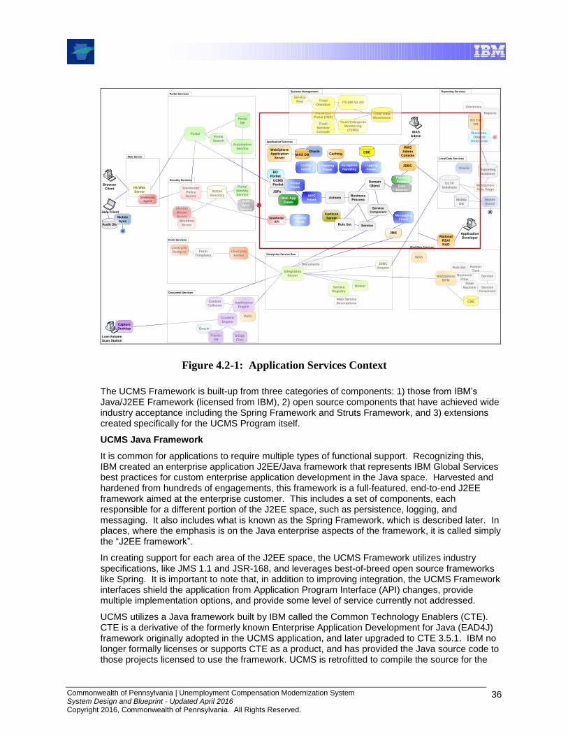
Commonwealth of Pennsylvania | Unemployment Compensation Modernization System System Design and Blueprint - Updated April 2016 Copyright 2016, Commonwealth of Pennsylvania. All Rights Reserved.
36
WebSphere
BPM
BO Ent
DB
Universes
Enterprise Service Bus
Documents
WAS
Web Service
Descriptions
Oracle
Integration
Server
JDBC
Adapter
Content
Engine
Content
Collector
LiveCycle
Forms
Service
Registry
JDBC
Portal
IIS Web
Server
Web Server
Form Services
Portal Services
Application Services
Actions
Corticon
Server
Rule Set
Domain
Object
JMS
Business
Process
OLTP
Database
Service Component
Service
Java Client
Systems Management
Tivoli Enterprise
Monitoring
(TEMS)
WebSphere
Data Stage
Local Data Services
WebSphere
Application
Server
FileNet
DB
Reporting Services
Tivoli Ent
Portal (TEP)Tivoli Data
Warehouse
ITCAM for AD
Document Services
Form
Templates
Broker
Automation
Service
Portal
Search
Portal
DB
Audit DB
Mobile
Sync
Oracle
JSPs
LiveCycle
Designer
Capture
Desktop
Image
Files
Application
Engine
BO
Portlet
Reports
UCMS
PortletSiteMinder
Policy
Server
Workflow
Server
Identity
Minder
Server
Security Services
Business
Flow
Human
Task
Service
Service Component
WAS
Workflow Services
CBE
State
Machine
Tivoli
Omnibus
Tivoli
Netview
Console
Mobile
Server
Business-
Objects
Enterprise
Mobile
DB
B
`
Browser
Client
`
Low-Volume
Scan Station
Service
Now
B
WAS DBCBE
Persist
Fmwk
C
C
Auth
Sync
Service
Caching
Config
FmwkCaching
Fmwk
Exception
Handling
Logging
FmwkCaching
Fmwk
Portal
Fmwk
MVC
Fmwk
Messaging
Fmwk
Web App
Fmwk
Data
Access
Rule Set
Active
Directory
Portal
Identity
Service
Reporting
Database
Oracle
SiteMinder
Agent
SiteMinder
API
Security
Fmwk
WAS
Admin
Console
`
WAS
Admin
Rational
RSA/
RAD
`
Application
Developer
Figure 4.2-1: Application Services Context
The UCMS Framework is built-up from three categories of components: 1) those from IBM’s Java/J2EE Framework (licensed from IBM), 2) open source components that have achieved wide industry acceptance including the Spring Framework and Struts Framework, and 3) extensions created specifically for the UCMS Program itself.
UCMS Java Framework
It is common for applications to require multiple types of functional support. Recognizing this, IBM created an enterprise application J2EE/Java framework that represents IBM Global Services best practices for custom enterprise application development in the Java space. Harvested and hardened from hundreds of engagements, this framework is a full-featured, end-to-end J2EE framework aimed at the enterprise customer. This includes a set of components, each responsible for a different portion of the J2EE space, such as persistence, logging, and messaging. It also includes what is known as the Spring Framework, which is described later. In places, where the emphasis is on the Java enterprise aspects of the framework, it is called simply the “J2EE framework”.
In creating support for each area of the J2EE space, the UCMS Framework utilizes industry specifications, like JMS 1.1 and JSR-168, and leverages best-of-breed open source frameworks like Spring. It is important to note that, in addition to improving integration, the UCMS Framework interfaces shield the application from Application Program Interface (API) changes, provide multiple implementation options, and provide some level of service currently not addressed.
UCMS utilizes a Java framework built by IBM called the Common Technology Enablers (CTE). CTE is a derivative of the formerly known Enterprise Application Development for Java (EAD4J) framework originally adopted in the UCMS application, and later upgraded to CTE 3.5.1. IBM no longer formally licenses or supports CTE as a product, and has provided the Java source code to those projects licensed to use the framework. UCMS is retrofitted to compile the source for the
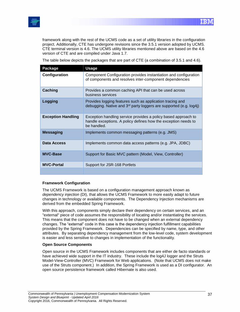
Commonwealth of Pennsylvania | Unemployment Compensation Modernization System System Design and Blueprint - Updated April 2016 Copyright 2016, Commonwealth of Pennsylvania. All Rights Reserved.
37
framework along with the rest of the UCMS code as a set of utility libraries in the configuration project. Additionally, CTE has undergone revisions since the 3.5.1 version adopted by UCMS. CTE terminal version is 4.6. The UCMS utility libraries mentioned above are based on the 4.6 version of CTE and are compiled under Java 1.7.
The table below depicts the packages that are part of CTE (a combination of 3.5.1 and 4.6).
Package Usage
Configuration Component Configuration provides instantiation and configuration of components and resolves inter-component dependencies
Caching Provides a common caching API that can be used across business services
Logging Provides logging features such as application tracing and debugging. Native and 3rd party loggers are supported (e.g. log4j)
Exception Handling Exception handling service provides a policy based approach to handle exceptions. A policy defines how the exception needs to be handled.
Messaging Implements common messaging patterns (e.g. JMS)
Data Access Implements common data access patterns (e.g. JPA, JDBC)
MVC-Base Support for Basic MVC pattern (Model, View, Controller)
MVC-Portal Support for JSR-168 Portlets
Framework Configuration
The UCMS Framework is based on a configuration management approach known as dependency injection (DI), that allows the UCMS Framework to more easily adapt to future changes in technology or available components. The Dependency Injection mechanisms are derived from the embedded Spring Framework.
With this approach, components simply declare their dependency on certain services, and an "external" piece of code assumes the responsibility of locating and/or instantiating the services. This means that the component does not have to be changed when an external dependency changes. The “external” code in this case is the dependency injection fulfillment capabilities provided by the Spring Framework. Dependencies can be specified by name, type, and other attributes. By separating dependency management from the low-level code, system development is easier and less sensitive to changes in implementation of the functionality.
Open Source Components
Open source in the UCMS Framework includes components that are either de facto standards or have achieved wide support in the IT industry. These include the log4J logger and the Struts Model-View-Controller (MVC) Framework for Web applications. (Note that UCMS does not make use of the Struts component.) In addition, the Spring Framework is used as a DI configurator. An open source persistence framework called Hibernate is also used.

Commonwealth of Pennsylvania | Unemployment Compensation Modernization System System Design and Blueprint - Updated April 2016 Copyright 2016, Commonwealth of Pennsylvania. All Rights Reserved.
38
It is worth noting that the configuration management and architectural approaches employed by the UCMS Framework permit/facilitate different choices on other projects should the Department wish or allow for future migration to different open source components on UCMS.
Extensions
This category of UCMS Framework component includes anything added to adapt to the specific technical environment of UCMS or to provide some specific capability that is not provided in a general-purpose framework. Two such components are an adapter from the security framework component to the SiteMinder security application API, and a data access service that provides a front end to an open source persistence framework (in this case Hibernate).
The following diagram depicts the UCMS Framework components that implement the high-level functions in the preceding Application Services Context diagram.
Figure 4.2-2: Application Services Components
The sections that follow will describe each component of the UCMS Framework.
4.2.2 Configuration Management
4.2.2.1 Introduction In determining the best practice approach to configuring UCMS Framework components, the goal was to provide isolation among the layers of an application such that DLI could freely use alternate technical implementations of components, such as the presentation and persistence layers, without reworking the applications. In other words, the goal was to be able to “wire” these different solutions together when required but to keep the business logic independent of them.
Commonwealth of Pennsylvania | Unemployment Compensation Modernization System System Design and Blueprint - Updated April 2016 Copyright 2016, Commonwealth of Pennsylvania. All Rights Reserved.
39
The solution was to employ the principle of dependency injection by using Spring, a very popular J2EE open source framework. In fact, even the applications are isolated from that framework, via a Component Configuration Service.
This section first explains the principle of Dependency Injection. It then describes the Component Configuration Service and Spring usage.
4.2.2.2 Dependency Injection Software components are a subset of collaborating components which depend upon other components (constructed as Services) to successfully complete their intended purpose. In many scenarios, the components need to know “which” components to communicate with, “where” to locate them, and “how” to communicate with them.
One way of structuring the code is to let the clients embed the logic of locating and/or instantiating the services as a part of their operational logic, but if the access mechanism or interface for a service is changed, this can potentially require modifications to the source code for many other components or services. In addition, embedding the location/instantiation logic results in more complex code. Another way to structure the code is to have the clients declare their dependency on services, and have an "external" piece of code assume the responsibility of locating and/or instantiating the services and supplying the relevant service references to the clients when needed. In the latter method, client code typically does not have to be changed when the way to locate an external dependency changes. This approach is described as Dependency Injection (DI), and the "external" piece of code referred to earlier is either a somewhat more manageable hand coded connection mechanism, or an automated system implemented using one of a variety of DI frameworks. Due to the size of the UCMS application, a DI framework is used, which includes “auto-wiring” capability based on a number of criteria. However, the framework (Spring Framework) also allows hard-coded wiring which has advantages in some situations (such as better control over instantiation time, and over how objects are constructed).
Until the early 2000’s, it was common to separate an interface from the implementation. The “Factory” design pattern even allowed for hiding the complexity of instantiation (in other words, preparing an object for use). (A “design pattern” is a reusable solution to a commonly occurring software design problem.) However the mechanism to “locate” the services was often left to the clients. Moreover some parts of a solution also needed to be aware of the dependencies between the various services themselves, and thus implicitly had to work out the appropriate sequencing of such component initialization, and track and manage their life cycles. The IBM framework that was selected for use in UCMS reduces build effort and simplifies maintenance compared to the earlier techniques of ad-hoc adoption without thorough integration.
Using Dependency Injection requires that the software developer simply declares the dependencies, while the framework or the container works out the complexities of service instantiation, initialization, sequencing and supplying the service references to the software clients as required.
4.2.2.3 Component Configuration Service The Component Configuration Service exposes the ability to request a component. It encapsulates the details of accessing the configurator. This isolates the application from the specific DI technology employed. It also allows that more than one DI framework (and therefore more than one instantiated configurator) may be present within the application space.
The primary API for Component Configuration Service is the getObject operation on the ComponentConfigurationContext interface. The following sequence diagram shows how to obtain configured objects from the Component Configuration Service.

Commonwealth of Pennsylvania | Unemployment Compensation Modernization System System Design and Blueprint - Updated April 2016 Copyright 2016, Commonwealth of Pennsylvania. All Rights Reserved.
40
Figure 4.2-3: Configuration Service Sequence Diagram
The following describes each step a client must follow to obtain a configured object:
1. Get an instance of the Component ConfigurationFactory.
2. Get an instance of the Component Configuration Context which provides access to configured objects.
3. Invoke the getObject operation on the ComponentConfigurationContext passing the objectNameKey to indicate the object being requested.
4. If the configured object is retrieved successfully, it must be “casted” to the appropriate type that is needed by the client.
A more detailed look at the implementation, utilizing Spring, is shown in the following diagram.
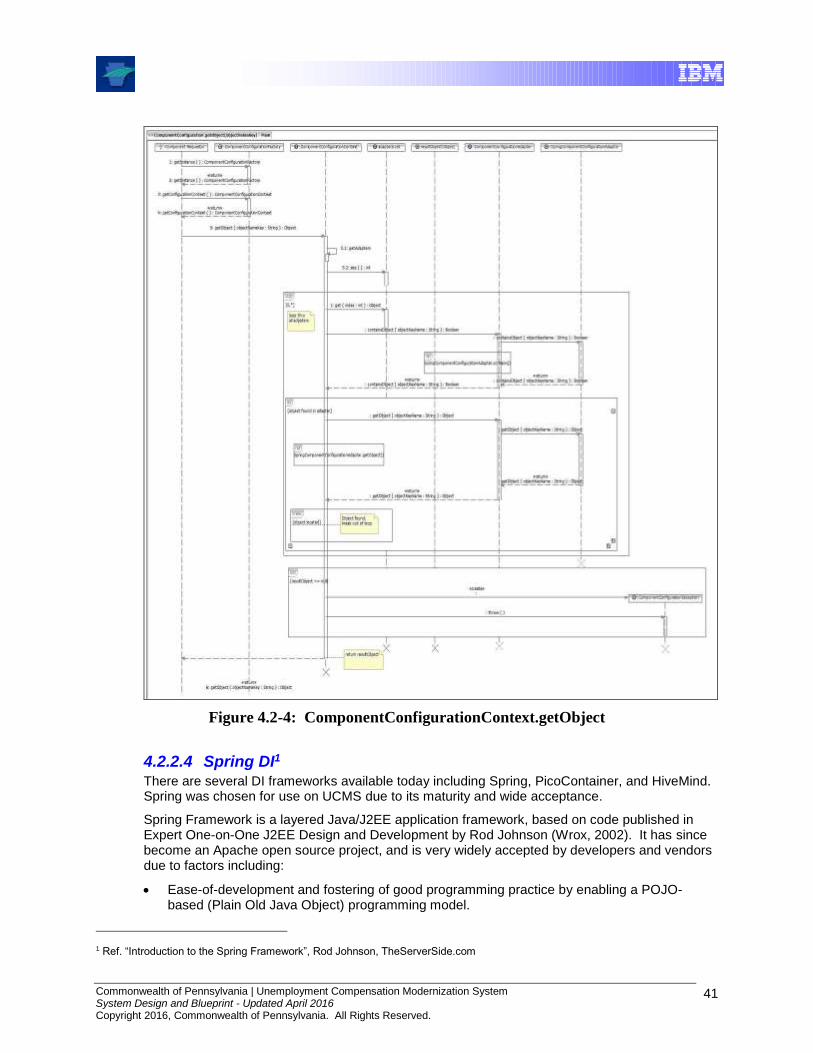
Commonwealth of Pennsylvania | Unemployment Compensation Modernization System System Design and Blueprint - Updated April 2016 Copyright 2016, Commonwealth of Pennsylvania. All Rights Reserved.
41
Figure 4.2-4: ComponentConfigurationContext.getObject
4.2.2.4 Spring DI1 There are several DI frameworks available today including Spring, PicoContainer, and HiveMind. Spring was chosen for use on UCMS due to its maturity and wide acceptance.
Spring Framework is a layered Java/J2EE application framework, based on code published in Expert One-on-One J2EE Design and Development by Rod Johnson (Wrox, 2002). It has since become an Apache open source project, and is very widely accepted by developers and vendors due to factors including:
Ease-of-development and fostering of good programming practice by enabling a POJO-based (Plain Old Java Object) programming model.
1 Ref. “Introduction to the Spring Framework”, Rod Johnson, TheServerSide.com

Commonwealth of Pennsylvania | Unemployment Compensation Modernization System System Design and Blueprint - Updated April 2016 Copyright 2016, Commonwealth of Pennsylvania. All Rights Reserved.
42
Spring does not compete with existing solutions (e.g., popular open source logging and persistence frameworks), but instead makes existing technologies easier to use.
Spring’s DI-based configuration management services can be used in any architectural layer, in whatever runtime environment.
Supports multiple container types (Bean Factory, and Application Contexts), and multiple types of injection models (Constructor, or property-based)
Eases test burdens by separating unit testing from application integration concerns
Simplifies solution construction by placing responsibility for object life cycle issues (instantiation, initialization, operation, and destruction) in the framework, instead of in all of the code modules. This results in cleaner, more use-focused construction as well, by separating business functions from routine implementation and management tasks.
Although the Spring Framework has many components, the UCMS Framework implements configuration management via the Component Configuration Service. These and other Java functions are based on the use of “JavaBeans” and/or “Enterprise JavaBeans”. JavaBeans are reusable software components, constructed with Java. They typically encapsulate many functions into a single object (the Bean). Of particular note, they provide access to properties using what are known as “getter” (to get values) and “setter” (to change values) methods. These mechanisms are standardized, well documented, and the actual implementation is exposed via a standards-based eXtensible Markup Language (XML) declaration file.
The core of Spring is the “org.springframework.beans” package, designed for working with JavaBeans. This package typically isn't used directly by users, but underpins much Spring functionality by incorporating common extensions to utilize Beans via Spring.
The next higher layer of abstraction is the bean factory. A Spring bean factory is a generic factory that enables objects to be retrieved by name, and which can manage relationships between objects, such as parent/child relationships. In fact, all of Spring is based on bean concepts.
Through its bean factory concept, Spring is a DI container. However, it is not a container in the sense of heavyweight containers such as, for example, EJB containers. A Spring BeanFactory is a container that can be created in a single line of code, and requires no special deployment steps. As a result, they are very easy to develop, utilize, and maintain.
Because the Spring container manages relationships between objects, it can add value where necessary through services such as transparent pooling for managed POJOs, and support for hot swapping, where the container introduces a level of indirection that allows the target of a reference to be swapped at runtime without affecting callers and without loss of thread safety. One of the beauties of Dependency Injection is that all this is possible transparently, with no API involved, and thus, with no coding changes required if the DI injector is changed.
Spring’s implementation approach is illustrated as follows.2
XML Declaration
The implementations that need to be instantiated are declared in the XML. Dependencies between services are also declared as “property” elements. Spring Framework uses this information to invoke the corresponding “setter” method to manipulate those properties when necessary. The following code snippet shows how these mechanisms are described in the hierarchical XML file:
2 Excerpted from “A Beginners Guide to Dependency Injection” by Dhananjay Nene, TheServerSide.com. http://www.theserverside.com/news/1364152/A-beginners-guide-to-Dependency-Injection

Commonwealth of Pennsylvania | Unemployment Compensation Modernization System System Design and Blueprint - Updated April 2016 Copyright 2016, Commonwealth of Pennsylvania. All Rights Reserved.
43
<beans>
<bean id="AirlineAgency"
class="com.dnene.ditutorial.common.impl.SimpleAirlineAgency"
singleton="true"/>
<bean id="CabAgency"
class="com.dnene.ditutorial.common.impl.SetterBasedCabAgency"
singleton="true">
<property name="airlineAgency">
<ref bean="AirlineAgency"/>
</property>
</bean>
<bean id="TripPlanner"
class="com.dnene.ditutorial.common.impl.SetterBasedTripPlanner"
singleton="true">
<property name="airlineAgency">
<ref bean="AirlineAgency"/>
</property>
<property name="cabAgency">
<ref bean="CabAgency"/>
</property>
</bean>
</beans>
Container Initialization
The container initialization typically requires a reference to the xml file and an instantiation of the BeanFactory. This results in the creation of a “resource” and can be performed with a single line of code; once created (the “new” method below), it can in turn be used to create a Factory:.
ClassPathResource res = new ClassPathResource("spring-beans.xml");
BeanFactory factory = new XmlBeanFactory(res);
Dependency Resolution
References to the services are retrieved based on the 'id' specified in the xml (not the interface class). Again all the services are implicitly instantiated in the appropriate order and the setters are called to resolve their dependencies.
factory.getBean("TripPlanner");

Commonwealth of Pennsylvania | Unemployment Compensation Modernization System System Design and Blueprint - Updated April 2016 Copyright 2016, Commonwealth of Pennsylvania. All Rights Reserved.
44
4.2.3 Model-View-Controller
4.2.3.1 Introduction The UCMS Application Services area is, at its core, based on Model-View-Controller ("MVC"), a universally recognized software architecture design pattern.
The MVC pattern provides a host of design benefits. It separates design concerns (data persistence and behavior, presentation, and control), decreasing code duplication, centralizing control, making the application more easily modifiable, and facilitating debugging. MVC also helps developers with different skill sets to focus on their core skills and collaborate through clearly defined interfaces. For example, a J2EE application project may include developers of custom tags, views, application logic, database functionality, and networking.
Furthermore, MVC provides a conceptual design core that can be extended by a framework to manage concerns such as:
Centralized control of such application facilities as security, logging, and screen flow.
Addition of new data sources by creating code that adapts the new data source to the view API.
Adaptation of new client type to operate as an MVC view.
In fact, these goals are realized in the UCMS Framework in the MVC and other areas.
The UCMS Framework provides an MVC implementation for a portal channel and MVC “Portal” components. Similarly, and although there is no usage within the scope of UCMS, an MVC implementation for Web applications is provided via Struts, demonstrating the flexibility of the UCMS Framework approach. Recognizing that other client types, such as Java applications or voice data, are or could be requirements in the future, the UCMS Framework adopts an innovative Multi-Channel MVC component that provides a common representation of the Model part of MVC. This preserves reusability of the business logic across a variety of delivery channels, and since changes to business logic are a major cause of code modifications, the use of an MVC Framework reduces code maintenance efforts and costs.
This section first provides a brief explanation of the MVC design pattern. It then describes the Multi-Channel MVC, and MVC Portal components as used in UCMS.
4.2.3.2 MVC MVC organizes an interactive application into three separate modules: one for the application model with its data representation and business logic, the second for views that provide data presentation and user input, and the third for a controller to dispatch requests and control flow. Most Web-tier application frameworks use some variation of the MVC design pattern.
Dividing an application into three layers--model, view, and controller--decouples their respective responsibilities. Each layer handles specific tasks and has specific responsibilities to the other areas, as shown with the solid and dotted arrows in the diagram, and in the description within each module.
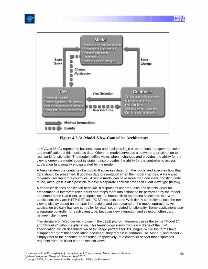
Commonwealth of Pennsylvania | Unemployment Compensation Modernization System System Design and Blueprint - Updated April 2016 Copyright 2016, Commonwealth of Pennsylvania. All Rights Reserved.
45
Figure 4.2-5: Model-View-Controller Architecture
In MVC, a Model represents business data and business logic or operations that govern access and modification of this business data. Often the model serves as a software approximation to real-world functionality. The model notifies views when it changes and provides the ability for the view to query the model about its state. It also provides the ability for the controller to access application functionality encapsulated by the model.
A View renders the contents of a model. It accesses data from the model and specifies how that data should be presented. It updates data presentation when the model changes. A view also forwards user input to a controller. A single model can have more than one view, boosting code reuse, although it is also possible to have a separate controller for each client view type (below).
A controller defines application behavior. It dispatches user requests and selects views for presentation. It interprets user inputs and maps them into actions to be performed by the model. In a stand-alone GUI client, user inputs include button clicks and menu selections. In a Web application, they are HTTP GET and POST requests to the Web tier. A controller selects the next view to display based on the user interactions and the outcome of the model operations. An application typically has one controller for each set of related functionality. Some applications use a separate controller for each client type, because view interaction and selection often vary between client types.
The literature on Web-tier technology in the J2EE platform frequently uses the terms "Model 1" and "Model 2" without explanation. This terminology stems from early drafts of the JSP specification, which described two basic usage patterns for JSP pages. While the terms have disappeared from the specification document, they remain in common use. Model 1 and Model 2 simply refer to the absence or presence (respectively) of a controller servlet that dispatches requests from the client tier and selects views.
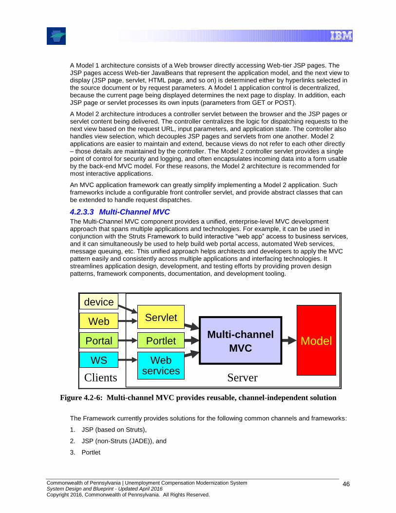
Commonwealth of Pennsylvania | Unemployment Compensation Modernization System System Design and Blueprint - Updated April 2016 Copyright 2016, Commonwealth of Pennsylvania. All Rights Reserved.
46
A Model 1 architecture consists of a Web browser directly accessing Web-tier JSP pages. The JSP pages access Web-tier JavaBeans that represent the application model, and the next view to display (JSP page, servlet, HTML page, and so on) is determined either by hyperlinks selected in the source document or by request parameters. A Model 1 application control is decentralized, because the current page being displayed determines the next page to display. In addition, each JSP page or servlet processes its own inputs (parameters from GET or POST).
A Model 2 architecture introduces a controller servlet between the browser and the JSP pages or servlet content being delivered. The controller centralizes the logic for dispatching requests to the next view based on the request URL, input parameters, and application state. The controller also handles view selection, which decouples JSP pages and servlets from one another. Model 2 applications are easier to maintain and extend, because views do not refer to each other directly – those details are maintained by the controller. The Model 2 controller servlet provides a single point of control for security and logging, and often encapsulates incoming data into a form usable by the back-end MVC model. For these reasons, the Model 2 architecture is recommended for most interactive applications.
An MVC application framework can greatly simplify implementing a Model 2 application. Such frameworks include a configurable front controller servlet, and provide abstract classes that can be extended to handle request dispatches.
4.2.3.3 Multi-Channel MVC The Multi-Channel MVC component provides a unified, enterprise-level MVC development approach that spans multiple applications and technologies. For example, it can be used in conjunction with the Struts Framework to build interactive “web app” access to business services, and it can simultaneously be used to help build web portal access, automated Web services, message queuing, etc. This unified approach helps architects and developers to apply the MVC pattern easily and consistently across multiple applications and interfacing technologies. It streamlines application design, development, and testing efforts by providing proven design patterns, framework components, documentation, and development tooling.
ServerClients
Portlet
Servlet
Webservices
device
Web
Portal
WS
ModelMulti-channel
MVC
Figure 4.2-6: Multi-channel MVC provides reusable, channel-independent solution
The Framework currently provides solutions for the following common channels and frameworks:
1. JSP (based on Struts),
2. JSP (non-Struts (JADE)), and
3. Portlet

Commonwealth of Pennsylvania | Unemployment Compensation Modernization System System Design and Blueprint - Updated April 2016 Copyright 2016, Commonwealth of Pennsylvania. All Rights Reserved.
47
For UCMS, the portlet support is used, as UCMS is a portal solution. (Note that UCMS does not make use of the Struts or JADE components built into the IBM J2EE Framework from which the UCMS Framework derives. However, aspects of these components exist in the UCMS Framework. Struts is covered in this document for possible reference on other projects implementing a Web application. JADE is an IBM alternative to Struts and is not covered in this document.)
Inbound and Outbound Solutions
Channel X
Mc-MVC
Model
Channel X
Mc-MVC
Model Server
xController Model
ModelFacade:
Command
Object(s)
ResultResultHandler
/ Chain
Inbound
Outbound
xClient
Figure 4.2-7: Inbound and Outbound Solutions
Multi-channel MVC consists of two essentially independent sub-solutions: the inbound path processes a client request to the Model, and the outbound path processes the Model results into a response view. The inbound path uses commands to provide a standard, automated process for translating client requests from their channel representations into the invocations of target Model operations. This provides a standard client-Model protocol across all channels, and it removes the need for any manual coding of Model access, which provides solution consistency and reduces development and maintenance costs. The outbound path provides a flexible framework for processing Model results and formulating views, based on an extensible collection of various result handler components, which may include ones that are framework-provided, customized for third-party frameworks, or completely new. The inbound and outbound solutions can also be used independently from each other.

Commonwealth of Pennsylvania | Unemployment Compensation Modernization System System Design and Blueprint - Updated April 2016 Copyright 2016, Commonwealth of Pennsylvania. All Rights Reserved.
48
Inbound processing of requests
Channel X
Mc-MVC
Model
Channel X
Mc-MVC
ModelServer
xController Model
object
xRequest
CmdRequest
ModelFacade
Command Operation
Object(s) result
5. execute
args
marshal
2.
4. 6.
1.
0. 3.
Figure 4.2-8: Inbound path from client request to Model result
For a given channel X (e.g., servlet, portlet, web service, etc.), server-side inbound processing begins when a channel controller, “xController”, receives a request (or message) from a remote client. Assuming the request is intended to invoke a Model operation, the xController has two main responsibilities.
1. Create a CommandRequest object that is appropriate to the channel’s request type
2. Have the ModelFacade execute the CommandRequest, which will produce a “model result”
object.
The implementations of controllers and/or CommandRequests depend upon the technical details of a given channel, such as servlet, or channel framework, such as Struts. The MVC Framework provides these for common technologies. These implementations are provided as defaults or custom ones can be selected through configuration. Other than such possible configuration, no additional coding is required for inbound processing.
Outbound processing of Model results
Server
xController ResultHandlerChain
ResultHandlerResultHandlerResultHandlerResultHandler
xResponse
BaseResponse
xResponse
BaseResponse
1. formulateResponse
BaseRequest
xRequestxRequest
Object(s) resultObject(s) resultObject(s) result
2. formulateResponse…
3.
Figure 4.2-9: Outbound Path ResultHandlers called
The outbound processing of Model results constitutes the view layer of MVC.

Commonwealth of Pennsylvania | Unemployment Compensation Modernization System System Design and Blueprint - Updated April 2016 Copyright 2016, Commonwealth of Pennsylvania. All Rights Reserved.
49
For a given request-response pair, outbound processing uses the object(s) returned from invoking the target Model operation, along with any additional view objects, to prepare a response for the client. There are a multitude of possible scenarios for response processing depending on such things as the nature of the client, the results from the Model, the state of the client’s view, the view technologies or frameworks, etc. To accommodate such variations, the outbound path
uses the chain of responsibility design pattern. An ordered sequence of ResultHandlers is
obtained and processing control is passed to each in turn until one of them completes the
processing for the response. The composition of the ResultHandlers used in the chain is
configurable. This approach permits a blending of framework-provided and custom handlers, which can be composed to accommodate a wide variety of technical environments and design approaches.
4.2.3.4 Framework Portal Support IBM's working definition of portal technology is that “Portals provide a secure, single point of interaction with diverse information, business processes, and people, personalized to a user's needs and responsibilities.”
Stated another way, there are five capabilities of a portal that distinguish it from a web site. A portal should provide:
1. A single point of access to all resources associated with the portal domain
2. Personalized interaction with the portal services
3. Federated access to hundreds of data types and repositories, aggregated and categorized (federated access reduces or eliminates the need to copy data)
4. Collaboration technologies that bring people together
5. Integration with Applications and workflow systems
Java Specification Request (JSR) 168 is a portlet specification that standardizes the methodology to develop components for portal servers. It enables interoperability among portlets and portals. JSR-168, and the newer version called JSR-286, defines a set of APIs for portlets and addresses standardization for preferences, user information, portlet requests and responses, deployment packaging, and security. For instance, it codifies categories of portlet modes, including required modes (Edit, Help, View, etc.), optional modes (such as About), and vendor-specific modes. It defines window states (Normal, Minimized, and Maximized). It also defines mechanisms for the portlet to access transient (Request, Session, Context) and persistent data. And it describes how resources, portlets, and deployment descriptors are packaged together into one Web Application aRchive (WAR) file.
UCMS leverages the many benefits of portal and adheres to JSR 168 to isolate UCMS assets from changes in portal products.
The UCMS Framework provides a proper MVC implementation for UCMS applications and allows the mapping between application state, view and action to be done in an XML configuration file. The UCMS Framework also provides specific support for development using the JSR168 specification.
The most significant UCMS Framework JSR168 packages and classes are described on following page. Within the original IBM J2EE Framework, these were named as part of the “Amber” portal support functions, and the class names (below) reflect that.

Commonwealth of Pennsylvania | Unemployment Compensation Modernization System System Design and Blueprint - Updated April 2016 Copyright 2016, Commonwealth of Pennsylvania. All Rights Reserved.
50
Figure 4.2-10: Portlet Package
The portlet package – The JSR168 portlet package is one of the most important packages in the UCMS Framework. It has two classes:
AmberJsr168BasePortlet: it is the super class of all portlets in the UCMS Framework. It is responsible for encapsulating the JSR 168 API (encapsulation “hides” the VIEW, EDIT and HELP modes). It also provides convenience methods for handling exceptions, creating parameters, logging information, dealing with the Session and setting the Portlet mode.
AmberJsr168PortletAdapter: it extends the base portlet package and has convenience methods for executing an action by invoking an action handler. It also provides “undo” capability, that is, if an action fails, it will return the last valid Result.
The session package – The JSR 168 session package has the Session implementation which uses the Session defined in the JSR168 API. It has two methods:
public Object getAttribute(String name, int scope): this method returns the object bound with the specified name in this session under the PORTLET_SCOPE, or null if no object is bound under the name in that scope.
public void setAttribute(String name, Object value, int scope): this method binds an object to this session in the given scope, using the name specified. If an object of the same name in this scope is already bound to the session, that object is replaced.
The taglib package – The UCMS Framework JSR168 taglib package provides tags to deal with the UCMS Framework COMMON Result. The Result is usually stored in Session so the target (in the case of Portal a JSP) can retrieve it to display values.
The util package – The UCMS Framework JSR168 util package is also very important because it provides the UCMS Framework COMMON Parameters implementation to be used with the JSR168 API.

Commonwealth of Pennsylvania | Unemployment Compensation Modernization System System Design and Blueprint - Updated April 2016 Copyright 2016, Commonwealth of Pennsylvania. All Rights Reserved.
51
4.2.3.5 MVC Portal In a typical portal scenario, a DLI customer logs in by providing a user name and password. Once the user is authenticated, the login portlet retrieves the user’s security token using the Security Services component and establishes a user session with the Session Management Service of the JSR 168 portlet. The portlet then renders the desired page of the portal on the client browser. Each of these pages consists of many portlets.
Subsequently, the user requests a particular action on a portlet to be performed. The request comes to the portlet container as an HTTP post request. Based on this request, the portlet container invokes the particular portlet. The portlet, in turn, invokes business logic, and the response to the request is rendered to the user.
The MVC Portal component provides services, “MVCPortalServices”, for JSR 168-compliant portlets. It also provides “MVCPortalAdminServices”, which are administrative services used by the MVC Framework Configuration Component.
After the login operation, the login portlet uses the “setSecurityToken()” service of the “MVCPortalServices” to set the security token. This token is required for all subsequent portlet requests. Subsequently, application portlets use the “invokeModel()” service to execute business operations on the backend model.
The “invokeModel()” invokes the “ModelFacade” interface of “MultiChannel MVC” component to interact with the backend model. MVC Portal invokes “ModelFacade” services with session (PortalSession), request parameters (PortalParameters), security token and action code of the request.
The specific MVCPortalServices services offered to portlets include:
setSecurityToken – This method stores the credential for the user. During the login operation, the portlet stores the security credential for the session. Every user request is validated against the credential of the user and only if the user is authorized will the business operation be allowed.
getSecurityToken – This method gets the credential for the user.
getAction – This method is used to get an action. The action is one of the parameters in the portlet request.
getPortalSession – This method returns a channel-independent session from a portlet session. This session holds attributes, other associated objects and credential of the requester. This session is passed to the back-end engine (model). Before invoking a business method, the model extracts all relevant information from the session.
getRequestParameters – This method returns channel-independent request parameters from a portlet request. The parameters contains all request parameters as well as the locale of the requester. The parameters are passed to the backend engine (model). Before invoking a business method, the model extracts all parameters which are required to make a business request.
invokeModel – This method is called by the portlet to execute a business operation.
getNavigationOutcome – This method identifies the JSP page to render the response object. The model of a business operation returns a response object. The portlet invokes this method to translate the corresponding "outcome" for the response object. Based upon the "outcome", the portlet automatically invokes the JSP page to render the response object.
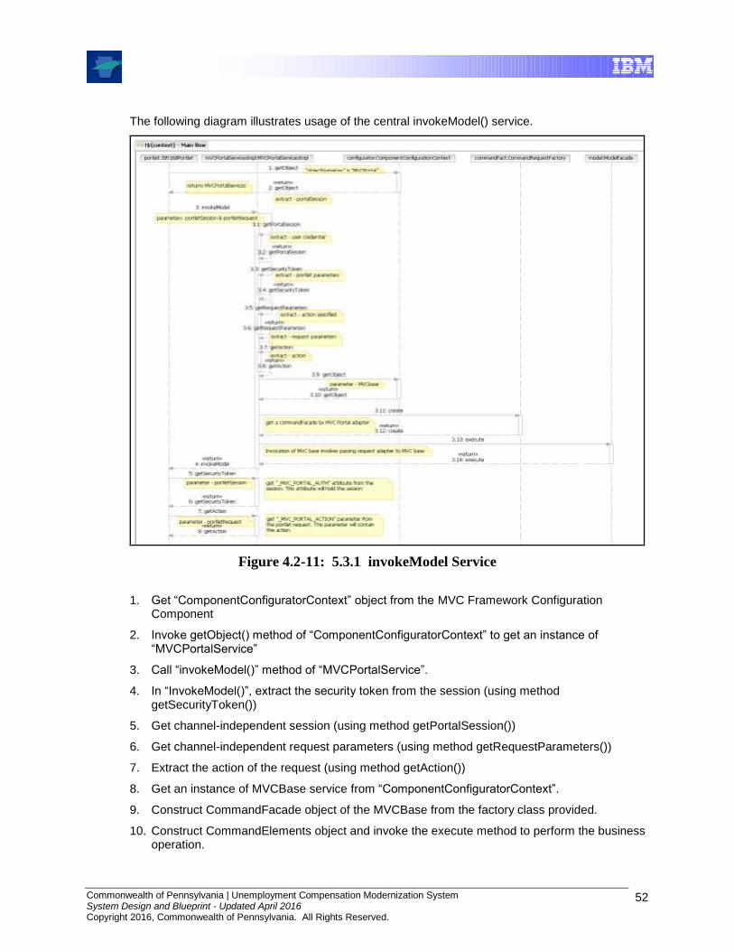
Commonwealth of Pennsylvania | Unemployment Compensation Modernization System System Design and Blueprint - Updated April 2016 Copyright 2016, Commonwealth of Pennsylvania. All Rights Reserved.
52
The following diagram illustrates usage of the central invokeModel() service.
Figure 4.2-11: 5.3.1 invokeModel Service
1. Get “ComponentConfiguratorContext” object from the MVC Framework Configuration Component
2. Invoke getObject() method of “ComponentConfiguratorContext” to get an instance of “MVCPortalService”
3. Call “invokeModel()” method of “MVCPortalService”.
4. In “InvokeModel()”, extract the security token from the session (using method getSecurityToken())
5. Get channel-independent session (using method getPortalSession())
6. Get channel-independent request parameters (using method getRequestParameters())
7. Extract the action of the request (using method getAction())
8. Get an instance of MVCBase service from “ComponentConfiguratorContext”.
9. Construct CommandFacade object of the MVCBase from the factory class provided.
10. Construct CommandElements object and invoke the execute method to perform the business operation.

Commonwealth of Pennsylvania | Unemployment Compensation Modernization System System Design and Blueprint - Updated April 2016 Copyright 2016, Commonwealth of Pennsylvania. All Rights Reserved.
53
11. The exact input objects that are required to perform a business operation will depend on the operation. It is expected that the portal will ensure that all input objects that are required to perform the business operation are available in the channel independent session.
12. Return the object returned by the Model.
4.2.3.6 Struts Struts is recognized as the most popular web application framework for Java. Although Struts is not used by UCMS, this description was kept in the Blueprint in case there are functions added in the future that could be simplified by using this (already included) part of Spring.
Struts provides its own web Controller component and integrates with other technologies to provide the Model and the View. For the Model, the Struts Framework can interact with standard data access technologies, like Java DataBase Connectivity (JDBC) and Enterprise Jave Beans (EJB), as well as almost any third-party package, like Hibernate, iBATIS, or Object Relational Bridge. For the View, the Struts Framework works well with JavaServer Pages, including JavaServer Pages Standard Tag Library (JSTL) and JavaServer Faces (JSF), as well as Velocity Templates, XSLT, and other presentation systems.
Struts’ Controller acts as a bridge between the application's Model and the web View. When a request is received, the Controller invokes an Action class. The Action class consults with the Model (or, a Facade representing the Model) to examine or update the application's state. The Struts Framework provides an ActionForm class to help transfer data between Model and View.
Most often, the Model is represented as a set of JavaBeans. Typically, developers use the Commons BeanUtils to transfer data between ActionForms and the Model objects (or a Facade). The Model does the "heavy lifting", and the Action acts as a "traffic cop" or adapter.
Struts uses a configuration file (struts-config.xml) to initialize its own resources. These resources include ActionForms to collect input from users, ActionMappings to direct input to server-side Actions, and ActionForwards to select output pages. The configuration file can also be used to specify validations for the ActionForms in an XML descriptor, using the Struts Validator.
Figure 4.2-12: Struts Overview

Commonwealth of Pennsylvania | Unemployment Compensation Modernization System System Design and Blueprint - Updated April 2016 Copyright 2016, Commonwealth of Pennsylvania. All Rights Reserved.
54
At a high level, a Struts implementation looks like the above. The system components include:
Client browser
An HTTP request from the client browser creates an event. The Web container will respond with an HTTP response.
Controller
The Controller receives the request from the browser, and makes the decision where to send the request. With Struts, the Controller is a command design pattern implemented as a servlet. The struts-config.xml file configures the Controller.
Business logic
The business logic updates the state of the model and helps control the flow of the application. With Struts this is done with an Action class as a thin wrapper to the actual business logic.
Model state
The model represents the state of the application. The business objects update the application state. ActionForm bean represents the Model state at a session or request level, and not at a persistent level. The JSP file reads information from the ActionForm bean using JSP tags.
View
The view is simply a JSP file. There is no flow logic, no business logic, and no model information -- just tags.
Struts Detail
The following diagram shows the interrelationship of the main Struts components:
Figure 4.2-13: Relationship of Command (ActionServlet) to Model (Action & ActionForm)
ActionServlet class
ActionServlet is the Command part of the MVC implementation and is the core of the MVC Framework. ActionServlet (Command) creates and uses Action, an ActionForm, and ActionForward. The struts-config.xml file configures the Command. During the creation of the Web project, Action and ActionForm are extended to solve the specific problem space. The file struts-config.xml instructs ActionServlet on how to use the extended classes. There are several advantages to this approach:
Commonwealth of Pennsylvania | Unemployment Compensation Modernization System System Design and Blueprint - Updated April 2016 Copyright 2016, Commonwealth of Pennsylvania. All Rights Reserved.
55
The entire logical flow of the application is in a hierarchical text file. This makes it easier to view and understand, especially with large applications.
The page designer does not have to wade through Java code to understand the flow of the application.
The Java developer does not need to recompile code when making flow changes.
ActionForm class
ActionForm maintains the session state for the Web application. ActionForm is an abstract class that is sub-classed for each input form model. When input form model is mentioned, what is meant is that ActionForm represents a general concept of data that is set or updated by an HTML form. For instance, there may be a UserActionForm that is set by an HTML Form. The Struts Framework:
Checks to see if a UserActionForm exists; if not, it will create an instance of the class.
Struts sets the state of the UserActionForm using corresponding fields from the HttpServletRequest, eliminating the need for complex request.getParameter() calls. For instance, the Struts Framework can take fname from request stream and call UserActionForm.setFname().
The Struts Framework updates the state of the UserActionForm before passing it to the business wrapper UserAction.
Before passing it to the Action class, Struts also performs state validation by calling the validation() method on UserActionForm.
Action class
The Action class is a wrapper around the business logic. The purpose of Action class is to translate the HttpServletRequest to the business logic. To use Action, a developer only needs to subclass and override the process() method.
The ActionServlet (Command) passes parameterized classes to ActionForm using the perform() method. Again, no more dreadful request.getParameter() calls. By the time the event gets to this point, the input form data (or HTML form data) has already been translated out of the request stream and into an ActionForm class.
Error classes
ActionError encapsulates an individual error message. ActionErrors is a container of ActionError classes that the View can access using tags. ActionErrors is Struts’ way of keeping up with a list of errors.

Commonwealth of Pennsylvania | Unemployment Compensation Modernization System System Design and Blueprint - Updated April 2016 Copyright 2016, Commonwealth of Pennsylvania. All Rights Reserved.
56
Figure 4.2-14: Relationship of the Command (ActionServlet) to the Model (Action)
ActionMapping class
An incoming event is normally in the form of an HTTP request, which the servlet Container turns into an HttpServletRequest. The Controller looks at the incoming event and dispatches the request to an Action class. The struts-config.xml determines what Action class the Controller calls. The struts-config.xml configuration information is translated into a set of ActionMapping, which are put into container of ActionMappings. (Classes that end with “s” are containers)
The ActionMapping contains the knowledge of how a specific event maps to specific Actions. The ActionServlet (Command) passes the ActionMapping to the Action class via the perform() method. This allows Action to access the information to control flow.
ActionMappings
ActionMappings is a collection of ActionMapping objects.
4.2.4 Data Access
4.2.4.1 Introduction Data Access provides the ability of data to be persistent and to outlive an instance of a program. It is central to all modern applications; however it does not come without its complexities. Database programming and storage subsystems are complex. Object-oriented programming is equally complex. The role of a Data Access component is to provide a subsystem that maps the concepts of object-oriented programming to the aspects of database storage, such that a clean separation of the two layers (objects and persisted data) is made. This separation enables each of the layers to apply well known patterns for their problem domain without mixing the complexities of each layer.
More importantly the use of a Data Access component, with clean separation of layers, enables development teams to focus on business logic instead of the routine task of storing and retrieving objects. The two primary goals of Data Access are:
Provide reusable, technology-agnostic components for object/relational mapping

Commonwealth of Pennsylvania | Unemployment Compensation Modernization System System Design and Blueprint - Updated April 2016 Copyright 2016, Commonwealth of Pennsylvania. All Rights Reserved.
57
Provide developers with a standard means of incorporating persistence functionality regardless of the specific persistence technology being used.
The UCMS Framework realizes these goals in the Data Access Service component. This component provides a standard interface for developers to incorporate persistence into their applications. The implementation of this component and its dependent components used for exception handling and logging are configured using the Component Configuration Service.
Some of the benefits of using this approach to Data Access include:
No vendor lock-in by allowing mix-and-match of best-of-breed tools.
Centralized resource management. Component Configuration Service manages the initialization of the low-level data access technology.
Clean handling of proprietary persistence errors with a standard suite of exception classes. Application developers can avoid complex boilerplate error “catches”/”throws”.
Integrated transaction management. The Data Access handles transaction semantics including database rollbacks when exceptions occur.
The first section describes the Data Access Service. This is followed by a discussion on open source persistence frameworks.
4.2.4.2 Data Access Service
DatabaseDomain
Object
Data
Access
Figure 4.2-15: Data Access
The Data Access Service is a generic layer that encapsulates how data flows to and from the Model Layer where business Domain Objects reside. In essence, the Model is unaware where the data lives or how it is stored, this knowledge is exclusive to the Data Access Service which is provided by the implementation of this service.

Commonwealth of Pennsylvania | Unemployment Compensation Modernization System System Design and Blueprint - Updated April 2016 Copyright 2016, Commonwealth of Pennsylvania. All Rights Reserved.
58
Figure 4.2-16: Data Access Service
The Data Access Service Component provides three interfaces; the DataAccessService, the TransactionService, and the BusinessQueryService. Each of these interfaces provide specific functionality that together forms the Data Access Service Component.
The TransactionService interface provides the methods needed to begin, commit and rollback a transaction. These methods offer user-friendly signatures to enable developers to work with Data Access Service transactions.
The BusinessQueryService interface provides the methods to create new queries and new query parameters to be added to queries. Custom queries can be specified using this interface which allows developers to describe the query parameters and values independent of the specific technology used to retrieve the data.
The DataAccessService interface is the primary interface for storing and retrieving business Domain Objects. There are no inheritance requirements of the Domain Objects. The makePersistent() method takes a Domain Object and stores it in database. The delete method deletes an object from the database. The findById() and findByQuery() methods are used to
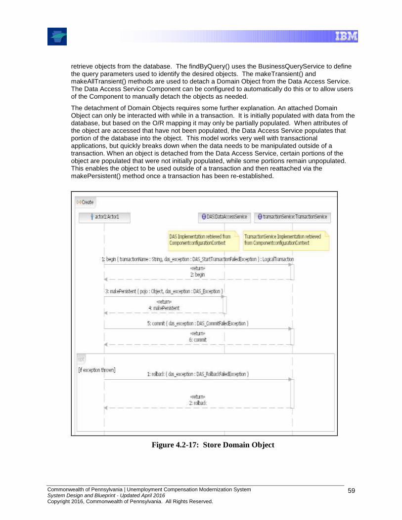
Commonwealth of Pennsylvania | Unemployment Compensation Modernization System System Design and Blueprint - Updated April 2016 Copyright 2016, Commonwealth of Pennsylvania. All Rights Reserved.
59
retrieve objects from the database. The findByQuery() uses the BusinessQueryService to define the query parameters used to identify the desired objects. The makeTransient() and makeAllTransient() methods are used to detach a Domain Object from the Data Access Service. The Data Access Service Component can be configured to automatically do this or to allow users of the Component to manually detach the objects as needed.
The detachment of Domain Objects requires some further explanation. An attached Domain Object can only be interacted with while in a transaction. It is initially populated with data from the database, but based on the O/R mapping it may only be partially populated. When attributes of the object are accessed that have not been populated, the Data Access Service populates that portion of the database into the object. This model works very well with transactional applications, but quickly breaks down when the data needs to be manipulated outside of a transaction. When an object is detached from the Data Access Service, certain portions of the object are populated that were not initially populated, while some portions remain unpopulated. This enables the object to be used outside of a transaction and then reattached via the makePersistent() method once a transaction has been re-established.
Figure 4.2-17: Store Domain Object
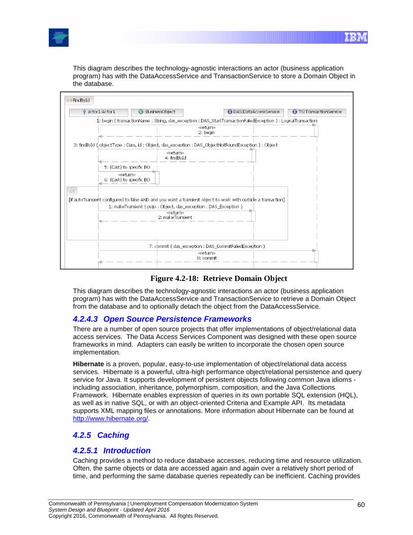
Commonwealth of Pennsylvania | Unemployment Compensation Modernization System System Design and Blueprint - Updated April 2016 Copyright 2016, Commonwealth of Pennsylvania. All Rights Reserved.
60
This diagram describes the technology-agnostic interactions an actor (business application program) has with the DataAccessService and TransactionService to store a Domain Object in the database.
Figure 4.2-18: Retrieve Domain Object
This diagram describes the technology-agnostic interactions an actor (business application program) has with the DataAccessService and TransactionService to retrieve a Domain Object from the database and to optionally detach the object from the DataAccessService.
4.2.4.3 Open Source Persistence Frameworks There are a number of open source projects that offer implementations of object/relational data access services. The Data Access Services Component was designed with these open source frameworks in mind. Adapters can easily be written to incorporate the chosen open source implementation.
Hibernate is a proven, popular, easy-to-use implementation of object/relational data access services. Hibernate is a powerful, ultra-high performance object/relational persistence and query service for Java. It supports development of persistent objects following common Java idioms - including association, inheritance, polymorphism, composition, and the Java Collections Framework. Hibernate enables expression of queries in its own portable SQL extension (HQL), as well as in native SQL, or with an object-oriented Criteria and Example API. Its metadata supports XML mapping files or annotations. More information about Hibernate can be found at http://www.hibernate.org/.
4.2.5 Caching
4.2.5.1 Introduction Caching provides a method to reduce database accesses, reducing time and resource utilization. Often, the same objects or data are accessed again and again over a relatively short period of time, and performing the same database queries repeatedly can be inefficient. Caching provides
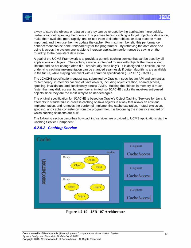
Commonwealth of Pennsylvania | Unemployment Compensation Modernization System System Design and Blueprint - Updated April 2016 Copyright 2016, Commonwealth of Pennsylvania. All Rights Reserved.
61
a way to store the objects or data so that they can be re-used by the application more quickly, perhaps without repeating the queries. The premise behind caching is to get objects or data once, make them available more rapidly, and re-use them until other objects or data become more important, and then use them to update the cache. For maximum benefit, this performance enhancement can be done transparently for the programmer. By retrieving the data once and using it across the system one is able to increase application performance by saving on the roundtrip to the persistent data store.
A goal of the UCMS Framework is to provide a generic caching service that can be used by all applications and layers. The caching service is intended for use with objects that have a long lifetime and do not change often (i.e., are virtually “read only”). It is designed be flexible, so the underlying caching implementation can be changed seamlessly if better algorithms are available in the future, while staying compliant with a common specification (JSR 107 (JCACHE)).
The JCACHE specification request was submitted by Oracle. It specifies an API and semantics for temporary, in-memory caching of Java objects, including object creation, shared access, spooling, invalidation, and consistency across JVM's. Holding the objects in memory is much faster than any disk access, but memory is limited, so JCACHE tracks the most-recently-used objects since they are the most likely to be needed again.
The original specification for JCACHE is based on Oracle’s Object Caching Services for Java. It attempts to standardize in-process caching of Java objects in a way that allows an efficient implementation, and removes the burden of implementing cache expiration, mutual exclusion, spooling, and cache consistency from the programmer. It is becoming the industry standard on which caching solutions are built.
The following section describes how caching services are provided to UCMS applications via the Caching Service Component.
4.2.5.2 Caching Service
Figure 4.2-19: JSR 107 Architecture
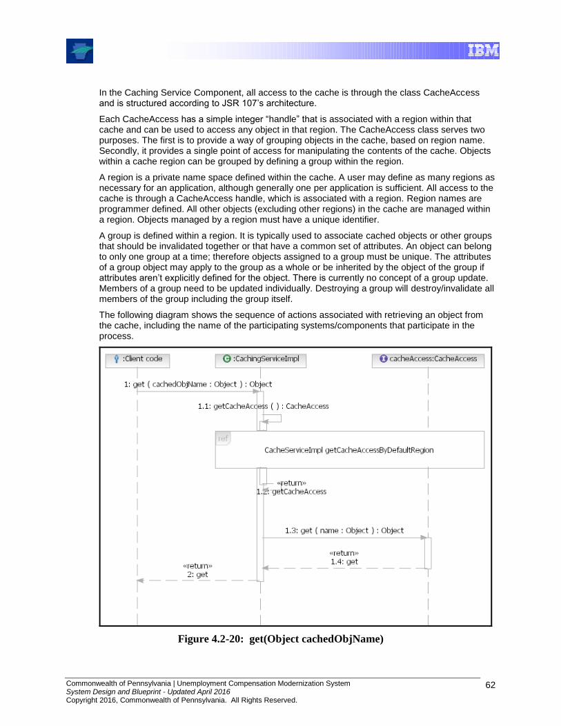
Commonwealth of Pennsylvania | Unemployment Compensation Modernization System System Design and Blueprint - Updated April 2016 Copyright 2016, Commonwealth of Pennsylvania. All Rights Reserved.
62
In the Caching Service Component, all access to the cache is through the class CacheAccess and is structured according to JSR 107’s architecture.
Each CacheAccess has a simple integer “handle” that is associated with a region within that cache and can be used to access any object in that region. The CacheAccess class serves two purposes. The first is to provide a way of grouping objects in the cache, based on region name. Secondly, it provides a single point of access for manipulating the contents of the cache. Objects within a cache region can be grouped by defining a group within the region.
A region is a private name space defined within the cache. A user may define as many regions as necessary for an application, although generally one per application is sufficient. All access to the cache is through a CacheAccess handle, which is associated with a region. Region names are programmer defined. All other objects (excluding other regions) in the cache are managed within a region. Objects managed by a region must have a unique identifier.
A group is defined within a region. It is typically used to associate cached objects or other groups that should be invalidated together or that have a common set of attributes. An object can belong to only one group at a time; therefore objects assigned to a group must be unique. The attributes of a group object may apply to the group as a whole or be inherited by the object of the group if attributes aren’t explicitly defined for the object. There is currently no concept of a group update. Members of a group need to be updated individually. Destroying a group will destroy/invalidate all members of the group including the group itself.
The following diagram shows the sequence of actions associated with retrieving an object from the cache, including the name of the participating systems/components that participate in the process.
Figure 4.2-20: get(Object cachedObjName)
Commonwealth of Pennsylvania | Unemployment Compensation Modernization System System Design and Blueprint - Updated April 2016 Copyright 2016, Commonwealth of Pennsylvania. All Rights Reserved.
63
The Caching Service Component provides user-friendly method signatures to handle caching for the application. Key functions provided via the Caching Service interface include:
Get/Put Cached Object – Provides variations including:
Get/Put Cached Object with cached object name, group name, region name
Get/Put Cached Object with cached object name, region name
Get/Put Cached Object with cached object name, group name, default region name
Get/Put Cached Object with cached object name, default region name
Define Group – Creates a new group within the cache region. Groups provide a logical grouping of objects in the cache so they can be loaded or invalidated concurrently. Group names must be unique within the region. Object names must be unique within the scope of the region not the group.
Replace Cached Object – Creates a new version of the object identified by name, replacing the current version with the object being passed in. If the object doesn’t exist in the cache, the replace operation is equivalent to a put. The attributes are inherited from the existing object or, if no object exists, from the group or region the object is associated with. Names are in the scope of a region so they must be unique within the region where they are placed.
Get Attributes – Returns an attribute object describing the current attributes associated with the object name (if given) or returns the attributes object for the specified/default region name (if no attribute name is given).
Reset Attributes – Allows some attributes for a region to be reset.
Invalidate – Marks all objects within the scope of name as invalid if the object name is given, or marks all objects in a specified/default region as invalid if the object name is not given. If name refers to a group object, invalidate cascades to all objects associated with the group or any subgroups.
Destroy – If an object name is not given, destroy will invalidate all objects within the specified/default cache region, removing all references to the objects from the cache including any loader(s) registered for the object(s). The CacheAccess object can no longer be used as it is closed. If an object name is given, destroy will invalidate all objects associated with name, removing all references to the objects from the cache including any loader registered for the object.
The implementation of the service interface serves as the facade of class CacheAccess from the UCMS Framework.
4.2.5.3 Framework Caching Support The caching component behind the Caching Service interface implements a seamless swapping of caching technologies that are based on the JSR standard. This is achieved through standard design patterns such as Interfaces, Concrete Factory and Abstract Factory. These were derived from the original IBM J2EE Framework class known as Quartz, as shown in the following diagram:

Commonwealth of Pennsylvania | Unemployment Compensation Modernization System System Design and Blueprint - Updated April 2016 Copyright 2016, Commonwealth of Pennsylvania. All Rights Reserved.
64
Figure 4.2-21: Cache Processing Class Diagram
The object model can be separated into two logical views: the Cache Access view, which centers on access to the cache and its data, and the Cache Administration view, which focuses on loading data into the cache and providing administrative features.
The Cache Access components include:
CacheAccess – This class provides an API for accessing the cache. Users can make a simple call to the caching service to add and also retrieve object from the cache.
CacheContext – This class provides a single access point for the caching service. This is where the cache gets initialized. During initialization, the default cache configuration file is read and the cache is setup. The context also provides access to the interfaces for manipulating and managing the cache via the CacheAccess and Cache respectively
CacheContextFactory – This is a singleton factory class. It is responsible for creating a CacheContext instance.
CacheAccessImpl – This class provides the default concrete implementation of the CacheAccess interface. This class stores the cache objects for its associated region name. Instead of having a single physical data store for cached objects they are stored in multiple data stores based on their region. Object within a cache region are stored and retrieved based on a unique key.
Attributes -- The Attributes class defines properties of how an object should be managed by the cache. Each object in the cache has an Attributes object associate with it. There is a default Attributes object that is applied to each object in the cache, if one is not defined at the
Commonwealth of Pennsylvania | Unemployment Compensation Modernization System System Design and Blueprint - Updated April 2016 Copyright 2016, Commonwealth of Pennsylvania. All Rights Reserved.
65
time it is placed into cache. Attributes for a given cached object can be retrieved by its unique key. Attributes can be assigned to a cached object, a group, and a region.
CacheObjectInfo – This class stores both informational and some statistical data about a cached object. CacheObjectInfo for a given cached object can be retrieved by its unique key.
The Cache Administrative components include:
Cache – This class provides advanced features for administering the caching service.
CacheLoader – To take advantage of automatic loading, a CacheLoader object is used and its load method is implemented to insert objects into the cache. The CacheLoader can be invoked directly by calling the CacheAccess.preLoad() method.
Configuration –There are two required configuration files for the caching functions: The bootstrap properties file contains the default values for initializing the cache. The quartz_config.xml file provides a way of grouping CacheLoader classes that need to be loaded into cache.
4.2.6 Exception Handling
4.2.6.1 Introduction Applications can differ on how they need to treat specific exceptions, but a common interface is highly desirable. Policy-driven exception handling is needed. Thus, an Exception Handling Component is part of the UCMS Framework.
Requirements met by the Exception Handling component include:
Allows components that generate or catch (respond to) exceptions to determine the appropriate exception handling policy for that exception. The source of the exception can be generated by the application, or the runtime environment (i.e., J2EE container, database, communication, etc.)
Exception handling polices are defined external to the application.
Supports multiple exception handling polices, such as:
Re-throw current exception
Throw a replacement exception.
Throw a replacement exception and nest the current exception.
Replace current exception with a system boundary exception (i.e., SOAP Faults, etc.)
Supports custom exception handlers.
Supports the ability to chain exception handlers.
This section describes the Exception Handling Component.
4.2.6.2 Exception Handling Component The functionality of the Exception Handling Component can be broken down into the following:
Initialize Generalized Policy framework
The policy framework defines a set of policies that are used by the exception handler framework to delegate a particular exception to an appropriate handler based on the returned policy. A policy can have a list of Factors that are referenced by the policy and specify matching parameters, a list of Actions to be taken if exceptions occur, and the handler to use to process an exception, along with a set of parameters that are used to achieve this.

Commonwealth of Pennsylvania | Unemployment Compensation Modernization System System Design and Blueprint - Updated April 2016 Copyright 2016, Commonwealth of Pennsylvania. All Rights Reserved.
66
Initialize exception handling
The Exception Handler initialization retrieves the generalized policies from the policy framework, converts them generalized policies to a useable form called ‘HandlerPolicies’, and defines four hash maps that contain the policies. The first map holds policies with a complete set of matching exception, class, and method. The second map contains policies that have only a matching exception and class, the third map contains policies that have only a matching class and method, and the fourth map includes policies that have only a matching exception. This provides a consistent way to deal with exceptions ranging from the very generic (map 4) to the very specific (map 1).
Invoking exception handling framework
The Exception Handler receives the request to handle a particular exception. It retrieves the policy for the particular exception based on a matching policy for the Exception’s Exception class name, Trapping class name, and Trapping method name, and the handler delegates the action to one of the Handler Action classes to perform one of the following handler functions:
Log Handler – Delegates the action to the Logging API component.
Replace Handler – Replaces the exception with another exception and throws the exception back to the exception handling framework.
Rethrow Handler – Rethrows the current exception back to the exception handling framework.
Wrap Handler – Wraps the exception into another exception and throws it back to the exception handling framework.
Custom developed handler
Figure 4.2-22: Implementation of Policy Component
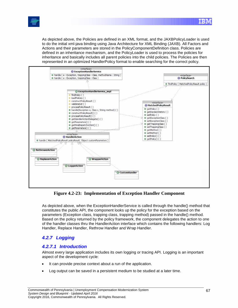
Commonwealth of Pennsylvania | Unemployment Compensation Modernization System System Design and Blueprint - Updated April 2016 Copyright 2016, Commonwealth of Pennsylvania. All Rights Reserved.
67
As depicted above, the Policies are defined in an XML format, and the JAXBPolicyLoader is used to do the initial xml-java binding using Java Architecture for XML Binding (JAXB). All Factors and Actions and their parameters are stored in the PolicyComponentDefinition class. Policies are defined in an inheritance mechanism, and the PolicyLoader is used to process the policies for inheritance and basically includes all parent policies into the child policies. The Policies are then represented in an optimized HandlerPolicy format to enable searching for the correct policy.
Figure 4.2-23: Implementation of Exception Handler Component
As depicted above, when the ExceptionHandlerService is called through the handle() method that constitutes the public API, the component looks up the policy for the exception based on the parameters (Exception class, trapping class, trapping method) passed in the handle() method. Based on the policy returned by the policy framework, the component delegates the action to one of the handler classes thru the HandlerAction interface which contains the following handlers: Log Handler, Replace Handler, Rethrow Handler and Wrap Handler.
4.2.7 Logging
4.2.7.1 Introduction Almost every large application includes its own logging or tracing API. Logging is an important aspect of the development cycle:
It can provide precise context about a run of the application.
Log output can be saved in a persistent medium to be studied at a later time.
Commonwealth of Pennsylvania | Unemployment Compensation Modernization System System Design and Blueprint - Updated April 2016 Copyright 2016, Commonwealth of Pennsylvania. All Rights Reserved.
68
A sufficiently rich logging package can be employed as an audit tool.
Inserting log statements into code is a low-tech method for debugging. It can also be the only way to debug some multithreaded applications and distributed applications.
It is desirable to have a common interface to a logging service that is independent of the implementation of that service. Thus, a logging solution is part of the UCMS Framework. Requirements met by the logging solution include:
Must allow an application to store messages in different locations. In general, the end users, system administrators and software developers will use these messages.
Operations should be made as inexpensive as possible. A logger allows application code to produce fine-grained logging when needed but not slow the application in normal production use.
Should provide mechanisms to dynamically change configuration on where to log messages and what messages to log.
Logging code is left in an application that goes into production, so the logging cost should be very little at runtime when it is not being used. To help achieve this, the logging system should define various logging levels.
Should provide a set of pre-defined handlers and should allow attaching new handlers if required. Handlers are used to publish log messages. It should be fairly straightforward to develop new Handlers. Developers requiring specific functionality can either develop a Handler from scratch or subclass one of the provided Handlers.
Should support a Formatter to localize and format the message before publishing. The component should provide some of the pre-defined formatters and it should be fairly easy to create new Formatters if required.
Should provide means to further control what records get logged, using filtering. The components should support custom filters.
An application can be broken down into different “areas” based on the package prefix of the classes involved. As a result, an entire application can be organized in a tree structure (the familiar dotted-name structure for that application). The logging component should allow setting different logging levels for different "areas" of the program, based on a match with the corresponding section of the tree. The Logging component should allow controlling things at the package level, or a set of packages levels.
Should support multiple loggers to be active simultaneously. Logging configuration should be loaded from the properties or XML file. The component should support simultaneous log locations. The following log locations must be implemented; event log, email message, database, message queue, text file and Windows Management Instrumentation (WMI) event.
Should provide an independent abstraction of logging toolkits available in the market. The logging services should be independence of logging products or specific logging APIs.
Should handle more complex logging of Objects such as CBEs (Common Base Events).
The UCMS Framework solution for logging utilizes log4j, an extremely reliable and robust logging framework as the base technology. This is integrated with the rest of the UCMS Framework via a Logging Service interface that is exposed to the applications. This section describes these components.
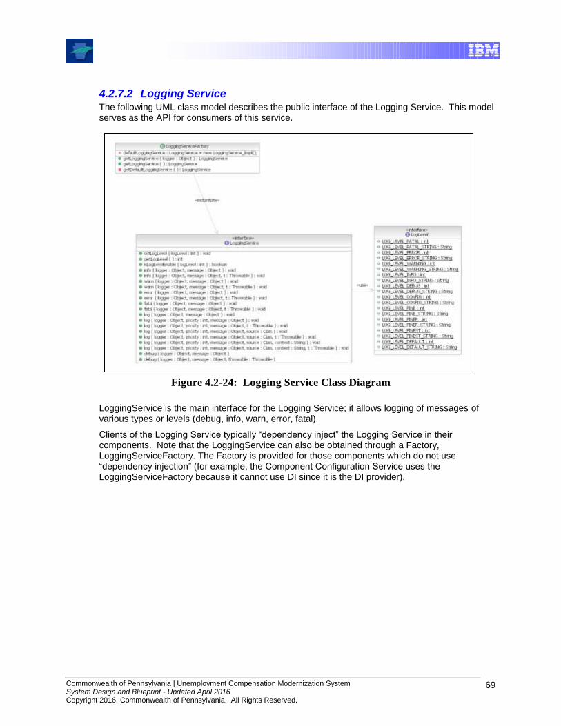
Commonwealth of Pennsylvania | Unemployment Compensation Modernization System System Design and Blueprint - Updated April 2016 Copyright 2016, Commonwealth of Pennsylvania. All Rights Reserved.
69
4.2.7.2 Logging Service The following UML class model describes the public interface of the Logging Service. This model serves as the API for consumers of this service.
Figure 4.2-24: Logging Service Class Diagram
LoggingService is the main interface for the Logging Service; it allows logging of messages of various types or levels (debug, info, warn, error, fatal).
Clients of the Logging Service typically “dependency inject” the Logging Service in their components. Note that the LoggingService can also be obtained through a Factory, LoggingServiceFactory. The Factory is provided for those components which do not use “dependency injection” (for example, the Component Configuration Service uses the LoggingServiceFactory because it cannot use DI since it is the DI provider).
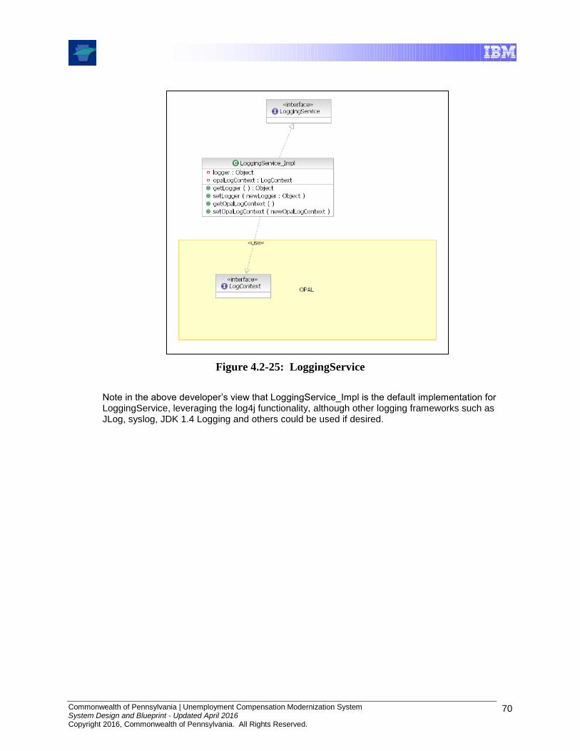
Commonwealth of Pennsylvania | Unemployment Compensation Modernization System System Design and Blueprint - Updated April 2016 Copyright 2016, Commonwealth of Pennsylvania. All Rights Reserved.
70
Figure 4.2-25: LoggingService
Note in the above developer’s view that LoggingService_Impl is the default implementation for LoggingService, leveraging the log4j functionality, although other logging frameworks such as JLog, syslog, JDK 1.4 Logging and others could be used if desired.
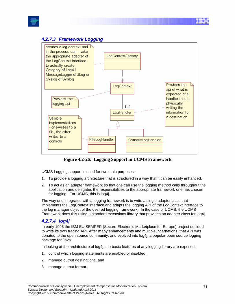
Commonwealth of Pennsylvania | Unemployment Compensation Modernization System System Design and Blueprint - Updated April 2016 Copyright 2016, Commonwealth of Pennsylvania. All Rights Reserved.
71
4.2.7.3 Framework Logging
Figure 4.2-26: Logging Support in UCMS Framework
UCMS Logging support is used for two main purposes:
1. To provide a logging architecture that is structured in a way that it can be easily enhanced.
2. To act as an adapter framework so that one can use the logging method calls throughout the application and delegates the responsibilities to the appropriate framework one has chosen for logging. For UCMS, this is log4j.
The way one integrates with a logging framework is to write a single adapter class that implements the LogContext interface and adapts the logging API of the LogContext interface to the log manager object of the desired logging framework. In the case of UCMS, the UCMS Framework does this using a standard extensions library that provides an adapter class for log4j.
4.2.7.4 log4j In early 1996 the IBM EU SEMPER (Secure Electronic Marketplace for Europe) project decided to write its own tracing API. After many enhancements and multiple incarnations, that API was donated to the open source community, and evolved into log4j, a popular open source logging package for Java.
In looking at the architecture of log4j, the basic features of any logging library are exposed:
1. control which logging statements are enabled or disabled,
2. manage output destinations, and
3. manage output format.

Commonwealth of Pennsylvania | Unemployment Compensation Modernization System System Design and Blueprint - Updated April 2016 Copyright 2016, Commonwealth of Pennsylvania. All Rights Reserved.
72
The first feature corresponds to the Logger, the central class in the log4j package. The second feature is implemented by Appenders. There are appenders for files, the console, Unix Syslog, NT Event Log, remote servers, SMTP e-mail, etc. The third feature is implemented by Layouts. The most popular layouts are the PatternLayout and HTMLLayout. The three components work together to enable developers to log messages according to message type and priority, and to control at runtime how these messages are formatted and where they are reported.
Category hierarchy3
The first and foremost advantage of any logging API over plain System.out.println calls
resides in its ability to disable certain log statements while allowing others to print unhindered. That capability assumes that the logging space, that is, the space of all possible logging statements, is categorized according to some developer-chosen criteria.
In conformance with that observation, the org.log4j.Category class is at the core of the
package. Categories are named entities. In a naming scheme familiar to Java developers, a category is said to be a parent of another category if its name, followed by a dot, is a prefix of the child category name (the dotted-name mechanism described earlier).
In the Category class, invoking the static getRoot() method retrieves the root category. The
static getInstance() method instantiates all other categories. getInstance() takes the
name of the desired category as a parameter. Some of the basic methods in the Category class
are listed below:
package org.log4j; public Category class { // Creation & retrieval methods: public static Category getRoot(); public static Category getInstance(String name); // printing methods: public void debug(String message); public void info(String message); public void warn(String message); public void error(String message); // generic printing method: public void log(Priority p, String message); }
Categories may be assigned priorities from the set defined by the org.log4j.Priority class.
Although the priority set matches that of the Unix Syslog system, log4j encourages the use of only four priorities: ERROR, WARN, INFO and DEBUG, listed in decreasing order of priority. The rationale behind that seemingly restricted set is to promote a more flexible category hierarchy rather than a static (even if large) set of priorities. Customized priorities may be defined by
subclassing the Priority class.
3 Excerpted from “Log4j delivers control over logging”, by Ceki Gulcu, IBM developerworks and JavaWorld
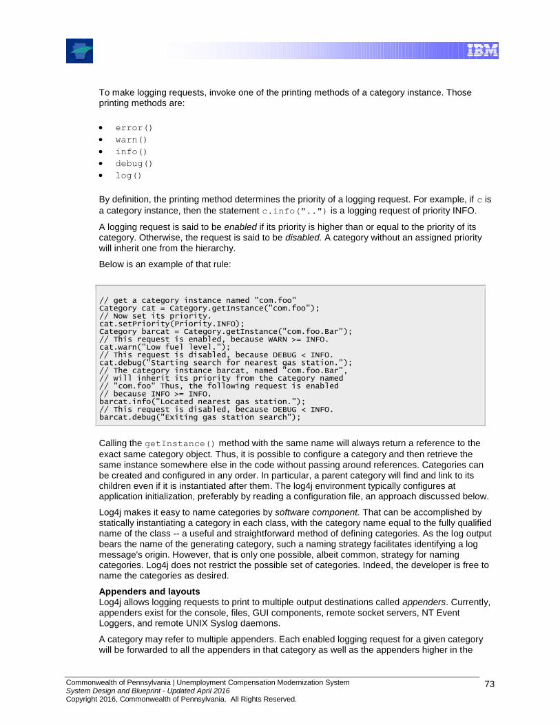
Commonwealth of Pennsylvania | Unemployment Compensation Modernization System System Design and Blueprint - Updated April 2016 Copyright 2016, Commonwealth of Pennsylvania. All Rights Reserved.
73
To make logging requests, invoke one of the printing methods of a category instance. Those printing methods are:
error()
warn()
info()
debug()
log()
By definition, the printing method determines the priority of a logging request. For example, if c is
a category instance, then the statement c.info("..") is a logging request of priority INFO.
A logging request is said to be enabled if its priority is higher than or equal to the priority of its category. Otherwise, the request is said to be disabled. A category without an assigned priority will inherit one from the hierarchy.
Below is an example of that rule:
// get a category instance named "com.foo" Category cat = Category.getInstance("com.foo"); // Now set its priority. cat.setPriority(Priority.INFO); Category barcat = Category.getInstance("com.foo.Bar"); // This request is enabled, because WARN >= INFO. cat.warn("Low fuel level."); // This request is disabled, because DEBUG < INFO. cat.debug("Starting search for nearest gas station."); // The category instance barcat, named "com.foo.Bar", // will inherit its priority from the category named // "com.foo" Thus, the following request is enabled // because INFO >= INFO. barcat.info("Located nearest gas station."); // This request is disabled, because DEBUG < INFO. barcat.debug("Exiting gas station search");
Calling the getInstance() method with the same name will always return a reference to the
exact same category object. Thus, it is possible to configure a category and then retrieve the same instance somewhere else in the code without passing around references. Categories can be created and configured in any order. In particular, a parent category will find and link to its children even if it is instantiated after them. The log4j environment typically configures at application initialization, preferably by reading a configuration file, an approach discussed below.
Log4j makes it easy to name categories by software component. That can be accomplished by statically instantiating a category in each class, with the category name equal to the fully qualified name of the class -- a useful and straightforward method of defining categories. As the log output bears the name of the generating category, such a naming strategy facilitates identifying a log message's origin. However, that is only one possible, albeit common, strategy for naming categories. Log4j does not restrict the possible set of categories. Indeed, the developer is free to name the categories as desired.
Appenders and layouts Log4j allows logging requests to print to multiple output destinations called appenders. Currently, appenders exist for the console, files, GUI components, remote socket servers, NT Event Loggers, and remote UNIX Syslog daemons.
A category may refer to multiple appenders. Each enabled logging request for a given category will be forwarded to all the appenders in that category as well as the appenders higher in the
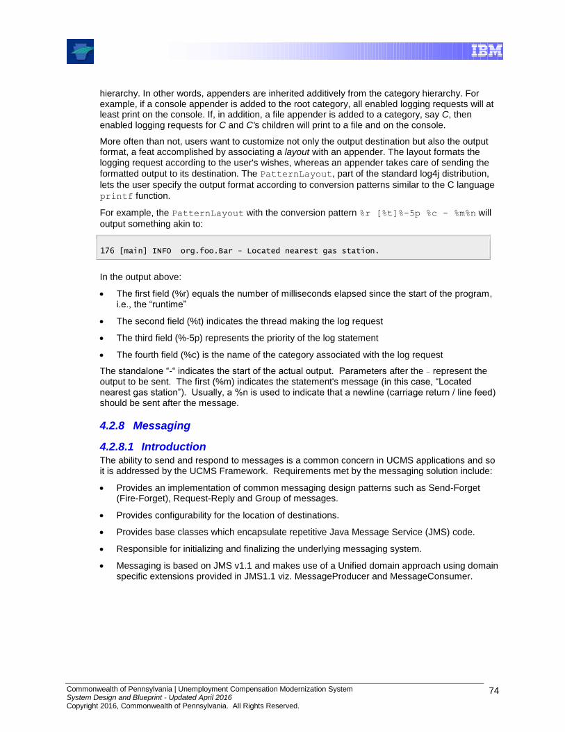
Commonwealth of Pennsylvania | Unemployment Compensation Modernization System System Design and Blueprint - Updated April 2016 Copyright 2016, Commonwealth of Pennsylvania. All Rights Reserved.
74
hierarchy. In other words, appenders are inherited additively from the category hierarchy. For example, if a console appender is added to the root category, all enabled logging requests will at least print on the console. If, in addition, a file appender is added to a category, say C, then enabled logging requests for C and C's children will print to a file and on the console.
More often than not, users want to customize not only the output destination but also the output format, a feat accomplished by associating a layout with an appender. The layout formats the logging request according to the user's wishes, whereas an appender takes care of sending the
formatted output to its destination. The PatternLayout, part of the standard log4j distribution,
lets the user specify the output format according to conversion patterns similar to the C language
printf function.
For example, the PatternLayout with the conversion pattern %r [%t]%-5p %c - %m%n will
output something akin to:
176 [main] INFO org.foo.Bar - Located nearest gas station.
In the output above:
The first field (%r) equals the number of milliseconds elapsed since the start of the program, i.e., the “runtime”
The second field (%t) indicates the thread making the log request
The third field (%-5p) represents the priority of the log statement
The fourth field (%c) is the name of the category associated with the log request
The standalone “-“ indicates the start of the actual output. Parameters after the – represent the output to be sent. The first (%m) indicates the statement's message (in this case, “Located nearest gas station”). Usually, a %n is used to indicate that a newline (carriage return / line feed) should be sent after the message.
4.2.8 Messaging
4.2.8.1 Introduction The ability to send and respond to messages is a common concern in UCMS applications and so it is addressed by the UCMS Framework. Requirements met by the messaging solution include:
Provides an implementation of common messaging design patterns such as Send-Forget (Fire-Forget), Request-Reply and Group of messages.
Provides configurability for the location of destinations.
Provides base classes which encapsulate repetitive Java Message Service (JMS) code.
Responsible for initializing and finalizing the underlying messaging system.
Messaging is based on JMS v1.1 and makes use of a Unified domain approach using domain specific extensions provided in JMS1.1 viz. MessageProducer and MessageConsumer.

Commonwealth of Pennsylvania | Unemployment Compensation Modernization System System Design and Blueprint - Updated April 2016 Copyright 2016, Commonwealth of Pennsylvania. All Rights Reserved.
75
Figure 4.2-27: Logical View of Messaging Framework
As shown above, the implementation of these requirements is met by a Messaging Service component, which provides the application interface, and by the UCMS Framework component that deals with enterprise messaging providers. This section describes these messaging UCMS Framework components.

Commonwealth of Pennsylvania | Unemployment Compensation Modernization System System Design and Blueprint - Updated April 2016 Copyright 2016, Commonwealth of Pennsylvania. All Rights Reserved.
76
4.2.8.2 Some Background on Messaging4 Enterprise messaging frameworks are designed to enable one or more applications to communicate despite a variety of obstacles such as incompatible formats, information sequence, user locale and language, etc. Common barriers include the requirement that both systems be running at the same time (synchronous communication), the need for multiple applications to receive the same message (multiple transmissions), the heterogeneity of most systems, and potential network failures.
Typically, enterprise architectures rely on message-oriented-middleware systems (MOMs) to channel messages between disparate systems. MOMs provide a common and reliable way for applications to create, exchange, and process messages without regard for the implementation details of the messaging client. Messages are sent to server destinations and domains rather than physical addresses. Messaging clients simply declare interest in a particular domain and destination, provide the proper security tokens to gain access to the domain in question, and then interact with the messaging server through that destination.
In a MOM system, clients are decoupled from one another, allowing them to maintain optimum quality of service without actually having to be "online" every second of the day. Once the requirement that applications always be available is removed, maintenance and scalability are much easier to manage. Applications can be brought down, updated, or refreshed for routine maintenance at almost any time of day, without affecting quality of service.
Java Message Service (JMS)
MOM servers allow disparate systems to exchange messages, but each MOM vendor has a proprietary API for handling messages. This lack of standardization is unacceptable in the Java technology development paradigm. To take advantage of the existing infrastructure of MOMs without sacrificing standardization, the J2EE platform offers JMS.
JMS defines the rules for message delivery in Java enterprise systems, and also declares interfaces to facilitate message exchange between application components and messaging systems (typically MOMs). JMS clients open connections to destinations on the MOM server and then send and receive messages on those destinations. JMS offloads the responsibilities of guaranteed delivery, message notification, message durability, and all of the underlying networking and routing issues to the messaging system. JMS and MOMs work well together because they divide responsibility between message clients and the messaging server.
Types of messaging
JMS supports two fundamental messaging mechanisms. The first is point-to-point messaging, in which a message is sent by one publisher (sender) and received by one subscriber (receiver). The second is publish-subscribe messaging, in which a message is sent by one or more publishers and received by one or more subscribers. While these two mechanisms are the actual foundation of JMS, many view the technology in terms of its three messaging models:
One-to-one messaging is a point-to-point model. A message is sent from one JMS client (publisher) to a destination on the server known as a queue. Another JMS client (subscriber) can access the queue and retrieve the message from the server. Multiple messages may reside on the queue, but each message is removed upon retrieval.
One-to-many messaging is a publish-subscribe model. A JMS client still publishes a message to a destination on the server, but the destination is now referred to as a topic. The key difference here is that messages placed in a topic include a parameter that defines the message durability (how long it should remain on the server awaiting subscribers). The
4 Excerpted from “J2EE pathfinder: Enterprise messaging with JMS” by Kyle Gabhart, IBM developerWorks

Commonwealth of Pennsylvania | Unemployment Compensation Modernization System System Design and Blueprint - Updated April 2016 Copyright 2016, Commonwealth of Pennsylvania. All Rights Reserved.
77
message will remain on the topic until all subscribers to the topic have retrieved a copy of the message or until its durability has expired, whichever comes first.
Many-to-many messaging – also a publish-subscribe model, extends one-to-many messaging. In addition to supporting multiple subscribers, this model also supports multiple publishers on the same topic. A good example of many-to-many messaging would be an e-mail listserve: multiple publishers can post messages on a topic, and all subscribers will receive each message.
Session beans and JMS
Session beans are designed to fulfill requests for business services. To the extent that an enterprise messaging system must be utilized to fulfill such a request, it (the enterprise message system) can be accessed transparently via a session bean. Combining session beans and JMS is a sensible enterprise-oriented solution. Using a session bean as a JMS client incorporates the JMS communication into the context of a larger business transaction. For example, a J2EE transaction could be set to retrieve a message from a JMS provider, extract data from that message, and then attempt to update the database. If the update fails, the transaction is rolled back, and another message can be sent to the JMS provider on a separate destination, describing the reason for the failed transaction.
Enterprise JavaBeans use resource manager connection factories to access extra-container resources. The resources are standard enterprise components that are not a core part of a J2EE container, including data sources, JMS sessions, JavaMail sessions, URL connections, and Java Connector Architecture (JCA) adapters. The resource manager component of a J2EE container manages the entire lifecycle of a particular type of resource, including connection pooling, transaction support, and necessary network protocols that make the actual connection possible.
Three steps enable an enterprise bean to obtain a connection to a JMS session: a Java Naming Directory and Interface (JNDI) lookup obtains a connection-factory reference, a connection is obtained via the factory reference, or the topic or queue connection object is used in the normal fashion for JMS. Because JMS must be supported by any J2EE-compliant application server, no additional libraries or components are required.
Combining JMS and session beans is a step forward in terms of enterprise functionality, and they reduce maintenance costs by relieving the programmer of substantial extra coding overhead, but they are not as simple or flexible as using separate mechanisms, and they impose additional restrictions (below). Using session beans provides the application developer access to the full range of J2EE functionality afforded by the EJB container, including JNDI, declarative transaction semantics, automatic concurrency support and resource management, declarative security, and access to other enterprise resources such as entity beans, datasources, JavaMail, and JCA adapters. From a messaging standpoint (unlike message-driven beans), the session bean-JMS combination imposes no limit on the number of topics and queues that your bean can access.
In exchange for enhanced enterprise features, asynchrony is sacrificed. Asynchrony is one of the major advantages of using an enterprise messaging technology like JMS, and losing it is no small thing. With JMS, messaging clients can send messages via the provider and then go offline, leaving the provider to transmit the message as time allows. Receiving clients can either log on periodically and check for new messages or set up a listener component that is always online awaiting new messages from the provider. Session beans are synchronous, and so cannot support the "always-on" listener component. Instead, a synchronous Java client must invoke a session bean method. The session bean method then opens a connection with a messaging provider to send and receive messages. To restore the simplicity while maintaining the advantages of stand-alone messaging components, a new approach was needed.

Commonwealth of Pennsylvania | Unemployment Compensation Modernization System System Design and Blueprint - Updated April 2016 Copyright 2016, Commonwealth of Pennsylvania. All Rights Reserved.
78
Message-driven beans
The EJB 2.0 specification defined a new type of enterprise bean. The new bean type, message-driven beans (MDBs), is intended to provide a reusable J2EE messaging component that can leverage existing investments in J2EE application servers, and EJB technology specifically.
MDBs are only intended to be invoked asynchronously through a JMS message. As a full-fledged JMS client, MDBs can both send and receive messages asynchronously via a MOM server. As an enterprise bean, MDBs are managed by the container and declaratively configured by an EJB deployment descriptor.
Message-driven beans are a powerful messaging solution on their own. Because they are specifically designed as message consumers and yet are still managed by the EJB container, MDBs offer a tremendous advantage in terms of scalability. Because message beans are stateless and managed by the container, they can both send and receive messages concurrently (the container simply grabs another bean out of the pool). This, combined with the inherent scalability of EJB application servers, produces a robust and scalable enterprise messaging solution.
4.2.8.3 Messaging Service The UCMS J2EE Messaging Service component provides a layer of abstraction for messaging systems. Clients of the Messaging Service are coded to a generic API, and configuration details specific to a messaging system are delegated to an XML configuration file.
The Messaging Service is primarily an implementation of commonly used messaging patterns including Send-Forget, Request-Reply, and Grouping of messages.
The Messaging Service Component provides messaging capability based on JMS1.1 Unified domain Interfaces like ConnectionFactory, Connection, Destination, Session, MessageProducer, and MessageConsumer.
The Messaging Service supports various message types similar to message types provided in JMS1.1. The message types that Messaging Service supports are: String Message, Stream Message, Object Message, Map Message and Bytes Message.
The Messaging Service provides synchronous sending and receiving of messages. If the application requires asynchronous message listening capabilities, it has to implement the Listener provided by the Messaging Service. Those listeners have to be registered with the Messaging Service.
What follows is the component model for the Messaging Service.

Commonwealth of Pennsylvania | Unemployment Compensation Modernization System System Design and Blueprint - Updated April 2016 Copyright 2016, Commonwealth of Pennsylvania. All Rights Reserved.
79
Figure 4.2-28: Messaging Service Component Model
Send and Forget Processing
In this scenario the sender of the message does not care about receiving a response back, placing the message in the queue is all the application is concerned about. This scenario is also used in web applications where a response it not needed immediately, such as when an email will be sent out as a response.
In Send and Forget, a messaging client calls the getProducerMessagingPattern() method to send messages. A client calls the getConsumerMessagingPattern() method to consume messages.
Request and Reply Processing
This is usually a synchronized scenario between one or more clients and one server. A request is placed in a queue which is serviced by a replier. The replier examines the request and places a response back, usually in a queue determined by the request.
The requester can then retrieve information on the reply queue. This is the most common scenario used in web applications in which existing functionality is exposed though a messaging channel.
For requesting the message in a Request-Reply scenario, a messaging pattern is first created by invoking the getRequestReplyMessagingPattern() method. Then calling createMessage() creates the request message. Invoking the sendMessage() method sends the request.
For replying to a request message in Request-Reply, a messaging pattern is created by invoking the getRequestReplyMessagingPattern() method. To receive the request message, the ReceiveSyncMessage() method is called. Then the reply message is created by invoking

Commonwealth of Pennsylvania | Unemployment Compensation Modernization System System Design and Blueprint - Updated April 2016 Copyright 2016, Commonwealth of Pennsylvania. All Rights Reserved.
80
createMessage, by using the pattern obtained from receiveSyncMessage(). Invoking sendMessage() sends the reply.
To receive reply message asynchronously the messaging client has to implement the AITMessageListener interface’s onMessage() method and consume it. If for Asynchronous messaging the client is using an MDB then the MDB class has to extend AITMessageListenerAdapter.
The messaging service implementation and connection to JMS are in Onyx.
4.2.8.4 Framework Enterprise Messaging Support The UCMS Framework provides support for Enterprise Messaging, for use with Java Message Service (JMS). There are two types of messaging models, publish-and-subscribe and point-to-point queuing.
Messages can be delivered asynchronously or synchronously. As a general rule, messages are delivered asynchronously because that is one of the key concepts/advantages of messaging systems. Synchronous messaging is provided for applications that require Remote Procedure Call (RPC)-like functionality using Messages.
The UCMS Framework provides a level of abstraction on top of MOM implementations, with a common API across different vendors while at the same time shielding the applications from any changes to the vendor implementations.
There is a single configuration file for the messaging application, which helps organize and define the configuration in one place instead of having it scattered across the entire application. Because the configuration is neatly organized in one place it is easier to check for inconsistencies instead of having to browse through many lines of code searching for different configuration options. This reduces solution complexity and maintenance costs.
Figure 4.2-29: Messaging Framework Support
The messaging support is designed to be used in conjunction with a Message Oriented Middleware (MOM) provider. It currently supports JMS and MQSeries. It can be used as the “client” or the “server” or both. This enables use as a client of an existing MQSeries server
Commonwealth of Pennsylvania | Unemployment Compensation Modernization System System Design and Blueprint - Updated April 2016 Copyright 2016, Commonwealth of Pennsylvania. All Rights Reserved.
81
application, or the server for an existing JMS application or be placed both in the client and server positions.
All the details of getting a connection, or a queue manager, or a session, are dealt with internally by the UCMS Framework, which is the plumbing of the messaging system, allowing developers to focus on solving the business needs of the application.
Point-to-Point Processing
P2P is usually implemented using queues. They represent a communication link (either synchronous or asynchronous) between two “points” on the network.
A Request is sent by placing a message in a queue, and a response is received in a reply queue. To achieve this functionality the UCMS Framework provides two classes: OnyxRequester and OnyxReplier, as the names imply the OnyxRequester plays the part of the requester while the OnyxReplier plays the part of the replier.
Publish and Subscribe Processing
A publish and subscribe scenario is one where a client can subscribe to one or more topics. Every message posted to a topic is delivered to all subscribers to that topic. This is a loosely coupled implementation where the publisher has no knowledge of its subscribers. To achieve this functionality the framework provides two classes: OnyxConsumer and OnyxProducer.
4.2.9 Security
4.2.9.1 Introduction Security is the ability for an application or application component to ensure that the user of the application is a known entity who has been authenticated, and that the user is authorized to perform the action. Authentication is the task of verifying that the user is who he says he is. Authorization is validating permission to perform a given action. The action may be to update a record, display information, or simply to navigate to another screen. In addition to authenticating and authorizing a user, audit information about who was authenticated, when, and what authorization requests were made, need to be captured.
The role of a security component is to provide a security framework for user authentication, authorization for fined grained access control, and to provide auditing when security requests are performed. For UCMS, the security component complements the security enforcement provided by SiteMinder at the Portal and Application Server levels. The security component provides a service interface for the application to interact with security services. The interface implementation is made as a configuration option. The primary benefit to this approach is the application is not bound to a specific vendor implementation of security.
The first section describes the Security Service. This is followed by an introduction to the UCMS Framework implementation of this service, and then a discussion on the SiteMinder Adapter needed to authenticate and authorize users.
4.2.9.2 Security Service
The Security Service is a generic layer that encapsulates how an application implements security functions such as authentication, authorization and security auditing. It provides a common interface for application components to verify that a user’s credentials are valid and that the user is entitled to perform the requested action. This separation of concerns is achieved through the SecurityService interface, allowing the business applications to be coded using the interface, without regard to the implementation of this interface.

Commonwealth of Pennsylvania | Unemployment Compensation Modernization System System Design and Blueprint - Updated April 2016 Copyright 2016, Commonwealth of Pennsylvania. All Rights Reserved.
82
Figure 4.2-30: Security Service
The Security Service Component provides one primary interface and two secondary interfaces. The primary interface is the SecurityService. This interface supports the primary security functions of authenticating, authorizing and auditing. To accomplish this it uses the two secondary interfaces: SecurityCredential and SecurityToken.
The SecurityService interface provides methods needed to create a SecurityCredential with user supplied credential information. The type of information used to create the credential is determined by the application and must be of a type that the particular security implementation supports. Implementations include User Id & Password, Security Assertion Markup Language (SAML) Credentials, Digital Certificates, etc. UCMS applications pass HTTP Session Headers as the user supplied credential information. This enables the SiteMinder Adapter to retrieve and interpret SiteMinder-specific headers to authenticate and authorize a user.
Once a SecurityCredential is created, it can be used to authenticate the user. The authenticate method takes a SecurityCredential as its input and returns a SecurityToken. This token may contain the SecurityCredential itself; or it may contain a SecurityPrinciple or other security related information. The contents of this token are unknown to the application; the application simply needs to pass the SecurityToken back to the SecurityService when checking if a user is authorized for a particular context/action.
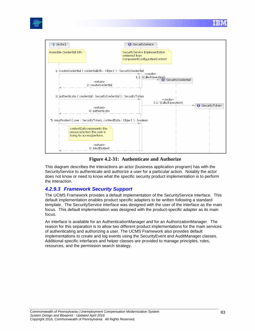
Commonwealth of Pennsylvania | Unemployment Compensation Modernization System System Design and Blueprint - Updated April 2016 Copyright 2016, Commonwealth of Pennsylvania. All Rights Reserved.
83
Figure 4.2-31: Authenticate and Authorize
This diagram describes the interactions an actor (business application program) has with the SecurityService to authenticate and authorize a user for a particular action. Notably the actor does not know or need to know what the specific security product implementation is to perform the interaction.
4.2.9.3 Framework Security Support The UCMS Framework provides a default implementation of the SecurityService interface. This default implementation enables product specific adapters to be written following a standard template. The SecurityService interface was designed with the user of the interface as the main focus. This default implementation was designed with the product-specific adapter as its main focus.
An interface is available for an AuthenticationManager and for an AuthorizationManager. The reason for this separation is to allow two different product implementations for the main services of authenticating and authorizing a user. The UCMS Framework also provides default implementations to create and log events using the SecurityEvent and AuditManager classes. Additional specific interfaces and helper classes are provided to manage principles, roles, resources, and the permission search strategy.
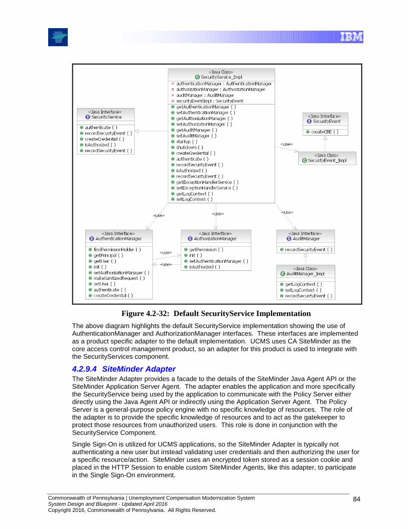
Commonwealth of Pennsylvania | Unemployment Compensation Modernization System System Design and Blueprint - Updated April 2016 Copyright 2016, Commonwealth of Pennsylvania. All Rights Reserved.
84
Figure 4.2-32: Default SecurityService Implementation
The above diagram highlights the default SecurityService implementation showing the use of AuthenticationManager and AuthorizationManager interfaces. These interfaces are implemented as a product specific adapter to the default implementation. UCMS uses CA SiteMinder as the core access control management product, so an adapter for this product is used to integrate with the SecurityServices component.
4.2.9.4 SiteMinder Adapter The SiteMinder Adapter provides a facade to the details of the SiteMinder Java Agent API or the SiteMinder Application Server Agent. The adapter enables the application and more specifically the SecurityService being used by the application to communicate with the Policy Server either directly using the Java Agent API or indirectly using the Application Server Agent. The Policy Server is a general-purpose policy engine with no specific knowledge of resources. The role of the adapter is to provide the specific knowledge of resources and to act as the gatekeeper to protect those resources from unauthorized users. This role is done in conjunction with the SecurityService Component.
Single Sign-On is utilized for UCMS applications, so the SiteMinder Adapter is typically not authenticating a new user but instead validating user credentials and then authorizing the user for a specific resource/action. SiteMinder uses an encrypted token stored as a session cookie and placed in the HTTP Session to enable custom SiteMinder Agents, like this adapter, to participate in the Single Sign-On environment.
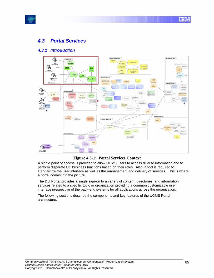
Commonwealth of Pennsylvania | Unemployment Compensation Modernization System System Design and Blueprint - Updated April 2016 Copyright 2016, Commonwealth of Pennsylvania. All Rights Reserved.
85
4.3 Portal Services
4.3.1 Introduction
WebSphere
BPM
BO Ent
DB
Universes
Enterprise Service Bus
Documents
WAS
Web Service
Descriptions
Oracle
Integration
Server
JDBC
Adapter
Content
Engine
Content
Collector
LiveCycle
Forms
Service
Registry
JDBC
Portal
IIS Web
Server
Web Server
Form Services
Portal Services
Application Services
Actions
Corticon
Server
Rule Set
Domain
Object
JMS
Business
Process
OLTP
Database
Service Component
Service
Java Client
Systems Management
Tivoli Enterprise
Monitoring
(TEMS)
WebSphere
Data Stage
Local Data Services
WebSphere
Application
Server
FileNet
DB
Reporting Services
Tivoli Ent
Portal (TEP)Tivoli Data
Warehouse
ITCAM for AD
Document Services
Form
Templates
Broker
Group Sync
Portal
Search
Portal
Repo
Audit DB
Mobile
Sync
Oracle
JSPs
LiveCycle
Designer
Capture
Desktop
Image
Files
Application
Engine
BO
Portlet
Reports
UCMS
PortletSiteMinder
Policy
Server
Workflow
Server
Identity
Minder
Server
Security Services
Business
Flow
Human
Task
Service
Service Component
WAS
Workflow Services
CBE
State
Machine
Tivoli
Omnibus
Tivoli
Netview
Console
Mobile
Server
Business-
Objects
Enterprise
Mobile
DB
B
`
Browser
Client
`
Low-Volume
Scan Station
Service
Now
B
WAS DBCBE
Persist
Fmwk
C
C
Auth
Sync
Service
Caching
Config
FmwkCaching
Fmwk
Exception
Handling
Logging
FmwkCaching
Fmwk
Portal
Fmwk
MVC
Fmwk
Messaging
Fmwk
Web App
Fmwk
Data
Access
Rule Set
Active
Directory
Portal
Identity
Service
Reporting
Database
Oracle
SiteMinder
Agent
SiteMinder
API
Security
Fmwk
WAS
Admin
Console
Portal
DevTools
Admin
Server
`
Portal
Developer
`
Portal
Administrator
`
Community
Manager
Figure 4.3-1: Portal Services Context
A single point of access is provided to allow UCMS users to access diverse information and to perform disparate UC business functions based on their roles. Also, a tool is required to standardize the user interface as well as the management and delivery of services. This is where a portal comes into the picture.
The DLI Portal provides a single sign-on to a variety of content, directories, and information services related to a specific topic or organization providing a common customizable user interface irrespective of the back-end systems for all applications across the organization.
The following sections describe the components and key features of the UCMS Portal architecture.

Commonwealth of Pennsylvania | Unemployment Compensation Modernization System System Design and Blueprint - Updated April 2016 Copyright 2016, Commonwealth of Pennsylvania. All Rights Reserved.
86
4.3.2 Component Overview
Figure 4.3-2: Portal Services Components
4.3.2.1 Run-Time
The following are the run-time components for the portal:
Portal Repo: Stores portal objects, such as user and group configurations, document records such as PDF files, and administrative objects. The portal database does not store the documents available through the portal. Source documents are left in their original locations which may include the Portal Document Repository. In the AEM implementation, the Portal Repo is a JCR (Content Repository API for Java) compliant object repository. More details can be found in the AEM portal documentation.
Adobe Experience Manager (AEM) Portal Server: Serves end user portal pages and content. The Portal enables end users to access portal content via My Pages, community pages, the Knowledge Directory, and Search. The Portal also enables administrative actions, such as setting preferences on portlets (which may be local or remote) or managing communities and portal setup.
Search Server: Returns indexed content stored within the portal. The Search Service returns content that is indexed in the AEM system from the Portal Publisher. Content that is indexed in AEM includes documents, portlets, communities, and users as well as many other portal objects. This server does not search custom application content, e.g., Worker Search functionality is not provided by this component.
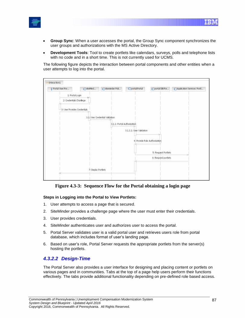
Commonwealth of Pennsylvania | Unemployment Compensation Modernization System System Design and Blueprint - Updated April 2016 Copyright 2016, Commonwealth of Pennsylvania. All Rights Reserved.
87
Group Sync: When a user accesses the portal, the Group Sync component synchronizes the user groups and authorizations with the MS Active Directory.
Development Tools: Tool to create portlets like calendars, surveys, polls and telephone lists with no code and in a short time. This is not currently used for UCMS.
The following figure depicts the interaction between portal components and other entities when a user attempts to log into the portal.
Figure 4.3-3: Sequence Flow for the Portal obtaining a login page
Steps in Logging into the Portal to View Portlets:
1. User attempts to access a page that is secured.
2. SiteMinder provides a challenge page where the user must enter their credentials.
3. User provides credentials.
4. SiteMinder authenticates user and authorizes user to access the portal.
5. Portal Server validates user is a valid portal user and retrieves users role from portal database, which includes format of user’s landing page.
6. Based on user’s role, Portal Server requests the appropriate portlets from the server(s) hosting the portlets.
4.3.2.2 Design-Time
The Portal Server also provides a user interface for designing and placing content or portlets on various pages and in communities. Tabs at the top of a page help users perform their functions effectively. The tabs provide additional functionality depending on pre-defined role based access.
Commonwealth of Pennsylvania | Unemployment Compensation Modernization System System Design and Blueprint - Updated April 2016 Copyright 2016, Commonwealth of Pennsylvania. All Rights Reserved.
88
Tier Two Pages: Displays a user-personalized view of the portal. Administrators can customize the Tier Two Pages by utilizing the Administration Pages (below) and add portlets which they think are more important to the users’ daily tasks.
Tier One Pages: While Tier Two Pages offer users a personalized view of the portal, communities offer a view of the portal that is shared by many users with a common interest (ex: UCMS Community, DLI Community). An Administrator can create a community and populate it with portlets to display content relevant to the community or that enables members of the community to work together. Under each community there can be multiple pages like Tax Data, Employer Registration etc. Under each page multiple portlets are available depending on the Users Role.
Administration Page: The Administration tab is used by the portal administrator to perform the portal administrative tasks. The Administration area provides access to the administrative object directory, which stores portal objects (such as communities, portlets, and users), and access to portal utilities (such as server configuration utilities). Depending on the permissions granted to portal administrators, they may see different menu items in the Administration area.
4.3.2.3 Administration and Monitoring
The following are the key tools or utilities available for administration and monitoring of the portal through the Admin Server. These tools/utilities, which are available via the Portal Administrative User Interface, include:
Activity Manager: Used to create, modify, or delete activities, and define which User Role(s) have what rights within the portal, e.g., Can Create Communities
Approve Objects for Migration: Approve migration packages, e.g. the administrator reviews and approves Migration Packages before moving portlets from Dev to Test
Audit Manager: Audits user activity or object activity
Automation Service: Configures and runs jobs such as the job to synchronize Active Directory domains for UCMS
Default Profiles: Configure default user profiles.
Global ACL Sync Map: Configure the global access control list (ACL) synchronization map
Migration – Export: Create a portal export package, to migrate objects like Communities or Portlets from the Development Portal to Test Portal
Migration – Import: Import an exported portal package
Portal Settings: Modify Portal URL settings
System Health Monitor: View diagnostic information
User Profile Manager: Modifies the user profiles map

Commonwealth of Pennsylvania | Unemployment Compensation Modernization System System Design and Blueprint - Updated April 2016 Copyright 2016, Commonwealth of Pennsylvania. All Rights Reserved.
89
4.3.3 Key Concepts, Features and Capabilities
4.3.3.1 Security and Services Integration
This section focuses on security and Web services integration, which include topics like authentication, authorization, and rights delegation specific to the portal.
SiteMinder Authentication & Authorization:
The authentication of users through the web portal and SiteMinder serves to only determine the user’s identity and validate their access to the portal application. This is referred to as “coarse-grained” authorization because it only identifies the users and does not determine which functions within the portal can be accessed.
The system uses SiteMinder to perform authorization by intercepting user requests to the portal, challenging the user for credentials, and validating the credentials against the SiteMinder Policy Server to verify that the user has access to the portal.
Portal Authorization:
Portlet authorization happens at the portal level. Once SiteMinder authenticates a user to the portal, the Portal takes control and checks its own database to make sure the user is synchronized in the portal registry. It then provides the user with a landing page and portlets based upon the user's role.
All users and groups are created in Active Directory (AD) only, and are synchronized to the Portal on a periodic basis. The roles, which consist of various AD Groups, are used in determining access to portlets.
Portlet Authorization:
The user's portlet-specific authorization decisions are controlled by WebSphere Application Server (WAS). The user's identity is asserted to WebSphere by passing the authenticated userID from the portal back to WebSphere via a session token inserted by SiteMinder.
4.3.3.2 JSR 168 Portlets
All UCMS portlets follow Java Specification Request (JSR) 168. JSR 168 is a specification that establishes a standard API for creating portlets. JSR 168 provides interoperability between portlets, Java-based portal servers, and other Web applications. More details about this JSR can be found at http://jcp.org/en/jsr/detail?id=168. By conforming to the JSR 168 specification, portlets lose some functionality available to portlets that are not JSR 168 compliant such as inline refresh and inter-portlet communication (which may, however, be available via a portal server API). However, the portability of JSR 168 portlets far outweighs the additional functionality available when using the vendor portlet API.
Portlet standards have evolved since UCMS was initially designed. New designs today would be likely to use the newer JSR-286 portlet specification. However, for an existing application like UCMS, there is little to be gained by converting to JSR-286 portlet format, and since considerable effort would be required to convert the approximately 200 current portlets to the new format, the effort would not provide substantial benefits.
AEM currently supports the JSR 168 specification as well as JSR-268 portlets. UCMS was not updated to JSR-268 during the migration to AEM.
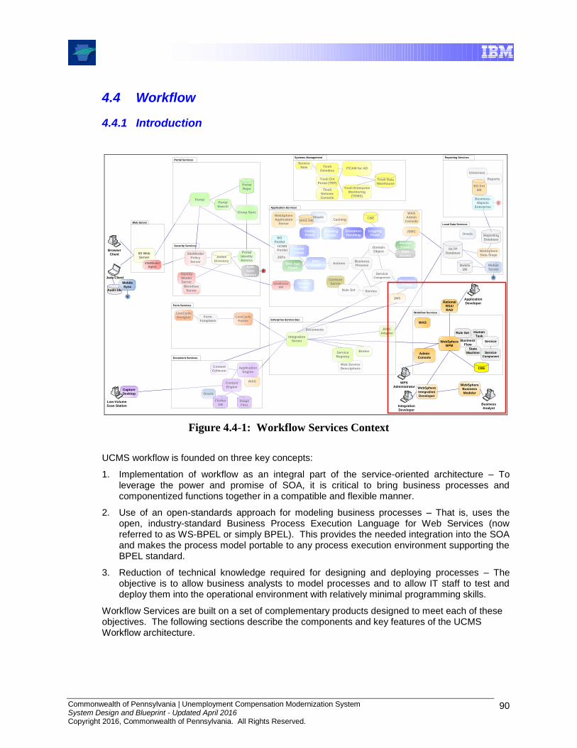
Commonwealth of Pennsylvania | Unemployment Compensation Modernization System System Design and Blueprint - Updated April 2016 Copyright 2016, Commonwealth of Pennsylvania. All Rights Reserved.
90
4.4 Workflow
4.4.1 Introduction
BO Ent
DB
Universes
Enterprise Service Bus
Documents
WAS
Web Service
Descriptions
Oracle
Integration
Server
JDBC
Adapter
Content
Engine
Content
Collector
LiveCycle
Forms
Service
Registry
JDBC
Portal
IIS Web
Server
Web Server
Form Services
Portal Services
Application Services
Actions
Corticon
Server
Rule Set
Domain
Object
JMS
Business
Process
OLTP
Database
Service Component
Service
Java Client
Systems Management
Tivoli Enterprise
Monitoring
(TEMS)
WebSphere
Data Stage
Local Data Services
WebSphere
Application
Server
FileNet
DB
Reporting Services
Tivoli Ent
Portal (TEP)Tivoli Data
Warehouse
ITCAM for AD
Document Services
Form
Templates
Broker
Group Sync
Portal
Search
Portal
Repo
Audit DB
Mobile
Sync
Oracle
JSPs
LiveCycle
Designer
Capture
Desktop
Image
Files
Application
Engine
BO
Portlet
Reports
UCMS
PortletSiteMinder
Policy
Server
Workflow
Server
Identity
Minder
Server
Security Services
Business
Flow
Human
Task
Service
Service Component
WAS
Workflow Services
CBE
State
Machine
Tivoli
Omnibus
Tivoli
Netview
Console
Mobile
Server
Business-
Objects
Enterprise
Mobile
DB
B
`
Browser
Client
`
Low-Volume
Scan Station
Service
Now
B
WAS DBCBE
Persist
Fmwk
C
C
Auth
Sync
Service
Caching
Config
FmwkCaching
Fmwk
Exception
Handling
Logging
FmwkCaching
Fmwk
Portal
Fmwk
MVC
Fmwk
Messaging
Fmwk
Web App
Fmwk
WebSphere
BPM
Data
Access
Rule Set
Active
Directory
Portal
Identity
Service
Reporting
Database
Oracle
SiteMinder
Agent
SiteMinder
API
Security
Fmwk
WAS
Admin
Console
Rational
RSA/
RAD
`
Application
Developer
`
WPS
Administrator
`
Integration
Developer
`
Business
Analyst
WebSphere
Integration
Developer
WebSphere
Business
Modeler
Admin
Console
Figure 4.4-1: Workflow Services Context
UCMS workflow is founded on three key concepts:
1. Implementation of workflow as an integral part of the service-oriented architecture – To leverage the power and promise of SOA, it is critical to bring business processes and componentized functions together in a compatible and flexible manner.
2. Use of an open-standards approach for modeling business processes – That is, uses the open, industry-standard Business Process Execution Language for Web Services (now referred to as WS-BPEL or simply BPEL). This provides the needed integration into the SOA and makes the process model portable to any process execution environment supporting the BPEL standard.
3. Reduction of technical knowledge required for designing and deploying processes – The objective is to allow business analysts to model processes and to allow IT staff to test and deploy them into the operational environment with relatively minimal programming skills.
Workflow Services are built on a set of complementary products designed to meet each of these objectives. The following sections describe the components and key features of the UCMS Workflow architecture.

Commonwealth of Pennsylvania | Unemployment Compensation Modernization System System Design and Blueprint - Updated April 2016 Copyright 2016, Commonwealth of Pennsylvania. All Rights Reserved.
91
4.4.2 Component Overview
Business
Flow
Human
Task
Service
Service Component
WAS
Workflow Services
CBE
State
Machine
WebSphere
BPM
Rule Set
Rational
RSA/
RAD
`
Application
Developer
`
WPS
Administrator
`
Integration
Developer
`
Business
Analyst
IBM
Integration
Designer
WebSphere
Business
Modeler
Admin
Console
Figure 4.4-2: Workflow Services Components
4.4.3 Run-Time
UCMS utilizes IBM Business Process Manager (BPM) for its workflow runtime engine and IBM Integration Designer (IID) as BPM’s integrated development environment (IDE).
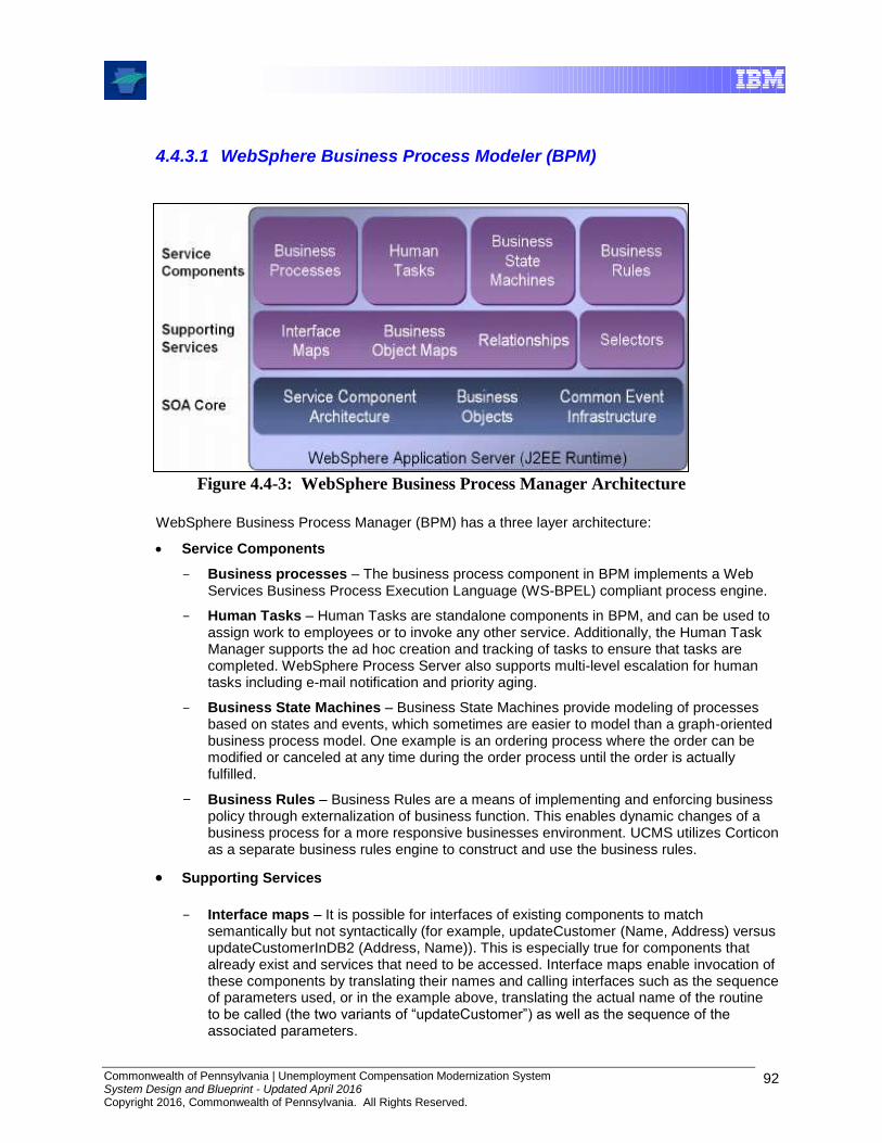
Commonwealth of Pennsylvania | Unemployment Compensation Modernization System System Design and Blueprint - Updated April 2016 Copyright 2016, Commonwealth of Pennsylvania. All Rights Reserved.
92
4.4.3.1 WebSphere Business Process Modeler (BPM)
Figure 4.4-3: WebSphere Business Process Manager Architecture
WebSphere Business Process Manager (BPM) has a three layer architecture:
Service Components
Business processes – The business process component in BPM implements a Web Services Business Process Execution Language (WS-BPEL) compliant process engine.
Human Tasks – Human Tasks are standalone components in BPM, and can be used to assign work to employees or to invoke any other service. Additionally, the Human Task Manager supports the ad hoc creation and tracking of tasks to ensure that tasks are completed. WebSphere Process Server also supports multi-level escalation for human tasks including e-mail notification and priority aging.
Business State Machines – Business State Machines provide modeling of processes based on states and events, which sometimes are easier to model than a graph-oriented business process model. One example is an ordering process where the order can be modified or canceled at any time during the order process until the order is actually fulfilled.
Business Rules – Business Rules are a means of implementing and enforcing business policy through externalization of business function. This enables dynamic changes of a business process for a more responsive businesses environment. UCMS utilizes Corticon as a separate business rules engine to construct and use the business rules.
Supporting Services
Interface maps – It is possible for interfaces of existing components to match semantically but not syntactically (for example, updateCustomer (Name, Address) versus updateCustomerInDB2 (Address, Name)). This is especially true for components that already exist and services that need to be accessed. Interface maps enable invocation of these components by translating their names and calling interfaces such as the sequence of parameters used, or in the example above, translating the actual name of the routine to be called (the two variants of “updateCustomer”) as well as the sequence of the associated parameters.
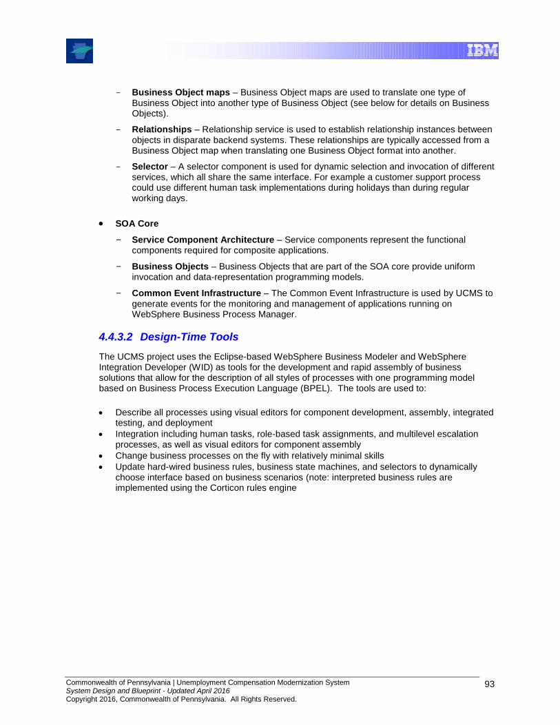
Commonwealth of Pennsylvania | Unemployment Compensation Modernization System System Design and Blueprint - Updated April 2016 Copyright 2016, Commonwealth of Pennsylvania. All Rights Reserved.
93
Business Object maps – Business Object maps are used to translate one type of Business Object into another type of Business Object (see below for details on Business Objects).
Relationships – Relationship service is used to establish relationship instances between objects in disparate backend systems. These relationships are typically accessed from a Business Object map when translating one Business Object format into another.
Selector – A selector component is used for dynamic selection and invocation of different services, which all share the same interface. For example a customer support process could use different human task implementations during holidays than during regular working days.
SOA Core
Service Component Architecture – Service components represent the functional components required for composite applications.
Business Objects – Business Objects that are part of the SOA core provide uniform invocation and data-representation programming models.
Common Event Infrastructure – The Common Event Infrastructure is used by UCMS to generate events for the monitoring and management of applications running on WebSphere Business Process Manager.
4.4.3.2 Design-Time Tools
The UCMS project uses the Eclipse-based WebSphere Business Modeler and WebSphere Integration Developer (WID) as tools for the development and rapid assembly of business solutions that allow for the description of all styles of processes with one programming model based on Business Process Execution Language (BPEL). The tools are used to:
Describe all processes using visual editors for component development, assembly, integrated testing, and deployment
Integration including human tasks, role-based task assignments, and multilevel escalation processes, as well as visual editors for component assembly
Change business processes on the fly with relatively minimal skills
Update hard-wired business rules, business state machines, and selectors to dynamically choose interface based on business scenarios (note: interpreted business rules are implemented using the Corticon rules engine
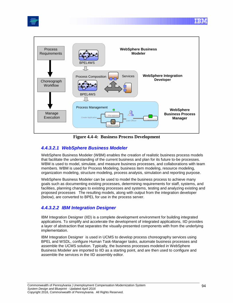
Commonwealth of Pennsylvania | Unemployment Compensation Modernization System System Design and Blueprint - Updated April 2016 Copyright 2016, Commonwealth of Pennsylvania. All Rights Reserved.
94
Figure 4.4-4: Business Process Development
4.4.3.2.1 WebSphere Business Modeler
WebSphere Business Modeler (WBM) enables the creation of realistic business process models that facilitate the understanding of the current business and plan for its future to-be processes. WBM is used to model, simulate, and measure business processes, and collaborations with team members. WBM is used for Process Modeling, business item modeling, resource modeling, organization modeling, structure modeling, process analysis, simulation and reporting purpose.
WebSphere Business Modeler can be used to model the business process to achieve many goals such as documenting existing processes, determining requirements for staff, systems, and facilities, planning changes to existing processes and systems, testing and analyzing existing and proposed processes The resulting models, along with output from the integration developer (below), are converted to BPEL for use in the process server.
4.4.3.2.2 IBM Integration Designer
IBM Integration Designer (IID) is a complete development environment for building integrated applications. To simplify and accelerate the development of integrated applications, IID provides a layer of abstraction that separates the visually-presented components with from the underlying implementation.
IBM Integration Designer is used in UCMS to develop process choreography services using BPEL and WSDL, configure Human Task-Manager tasks, automate business processes and assemble the UCMS solution. Typically, the business processes modeled in WebSphere Business Modeler are imported to IID as a starting point, and are then used to configure and assemble the services in the IID assembly editor.
Services
BPEL4WS
Process Composition
Process Requirements
Manage Execution
Process Management
Choreograph Workflow
WebSphere Business Modeler
WebSphere Integration Developer
WebSphere Business Process
Manager
BPEL4WS
Loan Officer Approved
Pre-approve
Check Credit
Create Application
Commonwealth of Pennsylvania | Unemployment Compensation Modernization System System Design and Blueprint - Updated April 2016 Copyright 2016, Commonwealth of Pennsylvania. All Rights Reserved.
95
4.4.3.3 Administrative and Monitoring
Administering BPM involves preparing, monitoring, and modifying the environment into which applications and resources are deployed, as well as working with the applications and resources themselves.
BPM offers several interfaces for administering the runtime environment. The sections below outline the different administrative and monitoring tools provided with BPM.
4.4.3.3.1 Administrative Console
The administrative console is a browser-based interface where an administrator can monitor, update, stop, and start a wide variety of applications, services, and resources for the applications running on BPM. The administrative console can also be used to work with relationships and to locate and resolve failed BPM events and processes.
The administrative console also provides administration capabilities for WebSphere Application Server and other customer-defined products.
4.4.3.3.2 Business Process Choreographer Explorer
Business Process Choreographer Explorer is a stand-alone Web application that provides a basic set of administration functions for managing business process and human tasks. Information about process templates, process instances, task instances, and associated objects can be viewed. These objects can also be acted on; for example, new process instances can be started or repaired, failed activities can be restarted, work items managed, etc.
4.4.3.3.3 Other Monitoring Methods
WebSphere BPM provides other non-visual methods of monitoring:
Scripting – The WebSphere administrative (wsadmin) program is a non-graphical command interpreter environment for running administrative options in a scripting language and submitting scripted programs for execution. It supports the same tasks as the administrative console. The wsadmin tool is intended for production environments and unattended operations.
Command-line Tools – Command-line tools are simple programs that can run from an operating system command-line prompt to perform specific tasks. Using these tools, administrators can start and stop application servers, check server status, add or remove nodes, and other tasks. The BPM command-line tools include the serviceDeploy command, which processes .jar, .ear, .war and .rar files exported from a WebSphere Integration Developer environment, and prepares them for installation to the production server(s).
Administrative programs – A set of Java classes and methods that utilize the Java Management Extensions (JMX) specification provide support for administering Service Component Architecture (SCA) and business objects. Each programming interface includes a description of its purpose, an example that demonstrates how to use the interface or class, and references to the individual method descriptions.
While monitoring of events occurs using the tools that are available with BPM, critical alerts are forwarded to Tivoli Omnibus for review and possible follow-up, e.g., creation of a DLI ServiceNow Ticket. Please refer to Section 8.0, Systems Management Architecture, for more information.
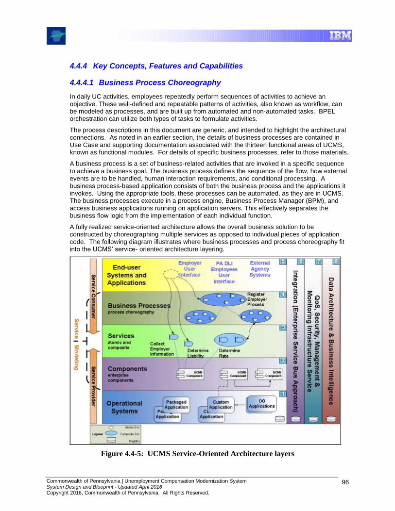
Commonwealth of Pennsylvania | Unemployment Compensation Modernization System System Design and Blueprint - Updated April 2016 Copyright 2016, Commonwealth of Pennsylvania. All Rights Reserved.
96
4.4.4 Key Concepts, Features and Capabilities
4.4.4.1 Business Process Choreography
In daily UC activities, employees repeatedly perform sequences of activities to achieve an objective. These well-defined and repeatable patterns of activities, also known as workflow, can be modeled as processes, and are built up from automated and non-automated tasks. BPEL orchestration can utilize both types of tasks to formulate activities.
The process descriptions in this document are generic, and intended to highlight the architectural connections. As noted in an earlier section, the details of business processes are contained in Use Case and supporting documentation associated with the thirteen functional areas of UCMS, known as functional modules. For details of specific business processes, refer to those materials.
A business process is a set of business-related activities that are invoked in a specific sequence to achieve a business goal. The business process defines the sequence of the flow, how external events are to be handled, human interaction requirements, and conditional processing. A business process-based application consists of both the business process and the applications it invokes. Using the appropriate tools, these processes can be automated, as they are in UCMS. The business processes execute in a process engine, Business Process Manager (BPM), and access business applications running on application servers. This effectively separates the business flow logic from the implementation of each individual function.
A fully realized service-oriented architecture allows the overall business solution to be constructed by choreographing multiple services as opposed to individual pieces of application code. The following diagram illustrates where business processes and process choreography fit into the UCMS’ service- oriented architecture layering.
Figure 4.4-5: UCMS Service-Oriented Architecture layers

Commonwealth of Pennsylvania | Unemployment Compensation Modernization System System Design and Blueprint - Updated April 2016 Copyright 2016, Commonwealth of Pennsylvania. All Rights Reserved.
97
The Business Process layer is broken down into two types of processes: Microflows and Macroflows.
Microflows are business processes that are short running, non-interruptible processes which execute as a single business transaction. A task being automatically routed from one employee to another due to workloads is an example of a microflow. By their nature, microflows cannot contain any human activities since they would cause the process to stop until a human performs the necessary activities (which could interrupt the flow, thus violating a basic premise of a microflow). Macroflows, on the other hand, are long running, interruptible business processes that can include activities which may require human interaction or a response from a remote service. Macroflows can wait for hours, days, or even years until the expected event occurs. For example, all business processes dealing with physical actions, such as scanning and printing of documents, are modeled and executed as macroflows. Macroflows can consist of multiple transactions, potentially a transaction for each individual activity.
4.4.4.2 Human Task Manager
As stated previously, Human Tasks are standalone components in BPM that can be used to assign work to employees or to invoke any other service. The Human Task Manager supports the ad hoc creation and tracking of tasks. Also supported is the multi-level escalation for human tasks including e-mail notification and priority aging. An important aspect of human tasks is that they can be suspended while the human worker gathers information or performs other non-automated tasks. As a result, these BPEL processes may require regular review to verify that they are being completed in a timely manner and not deferred indefinitely. Long suspensions can hinder infrastructure migration (such as upgrades). Even when that does not occur, lengthy suspension can result in other operational issues, and thus regular review is an essential part of process governance.
In general, there are three different types of tasks:
Participating Task: Executes the machine-to-human (M2H) scenario. This means that a service invokes a human, asking them to perform particular tasks or provide certain data before the process ends. The figure below, which is a scenario for verifying the wage record data for correctness, illustrates a Participating Task.
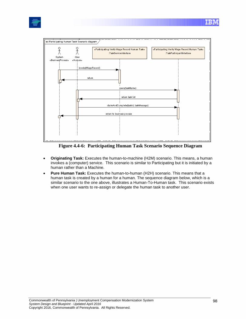
Commonwealth of Pennsylvania | Unemployment Compensation Modernization System System Design and Blueprint - Updated April 2016 Copyright 2016, Commonwealth of Pennsylvania. All Rights Reserved.
98
Figure 4.4-6: Participating Human Task Scenario Sequence Diagram
Originating Task: Executes the human-to-machine (H2M) scenario. This means, a human invokes a (computer) service. This scenario is similar to Participating but it is initiated by a human rather than a Machine.
Pure Human Task: Executes the human-to-human (H2H) scenario. This means that a human task is created by a human for a human. The sequence diagram below, which is a similar scenario to the one above, illustrates a Human-To-Human task. This scenario exists when one user wants to re-assign or delegate the human task to another user.

Commonwealth of Pennsylvania | Unemployment Compensation Modernization System System Design and Blueprint - Updated April 2016 Copyright 2016, Commonwealth of Pennsylvania. All Rights Reserved.
99
Figure 4.4-7: Purely Human-to-Human task Scenario Sequence Diagram
An additional task type is provided to extend the scenario between a human task and a business process:
Administrative Task: Executes administrative tasks, such as suspend or terminate, in business processes.
There are two ways to implement the relationship between human tasks and business processes:
Stand-alone task – A stand-alone task is a Service Component Architecture (SCA) component with human task implementation. An SCA component is a universal model for “business services” with an interface and an implementation (e.g. Java, BPEL, human task). The interface is defined by a Java interface or Web Service Description Language (WSDL) port type, depending on its implementation. For example, a human task implementation always has a WSDL port type as interface, despite the “web service” term.
Inline task – An inline task is defined in the BPEL process implementation. It can be implemented as a staff activity modeled on the business process level, and as task(s) on various activities (invoke, pick, receive, event handler, on message).

Commonwealth of Pennsylvania | Unemployment Compensation Modernization System System Design and Blueprint - Updated April 2016 Copyright 2016, Commonwealth of Pennsylvania. All Rights Reserved.
100
The following table summarizes which task types can be inline or stand-alone:
Task kind Inline task Stand-alone task
Task types Participating
Originating
Administrative
Participating
Originating
Pure Human
4.4.4.3 Integration
Business Processes and Human Tasks can be invoked by external clients as SCA components and the business process itself can invoke another business process as an SCA component. A business process resolves external services through partner links. The Business Object component of the SOA Core provides a standard data format for messages. The entire SCA component can be exported as a web service with a standard WSDL interface that can be invoked by external clients such as webMethods. Just like any other SCA Component, BPEL processes make use of the SCA Import, Export and Standalone Reference construct in order to facilitate interaction with external Components.
Figure 4.4-8: Business Process Enterprise Integration
In the diagram above, the “[R]” indicator represents a requirement that a component has on an interface to be provided by another component. The “(I)” indicator represents an addressable interface provided by the component. The lines that interconnect the components are implemented using messages, queues, or other mechanisms as appropriate for the component. The diagram shows an “Export” WSDL interface providing an addressable interface as an EntryPoint for external clients to invoke the SCA component generically referred to here as “Service Component”, implemented as a Business Process. This “Service Component” could be a process choreography or a Human Task Manager. The “Standalone Reference” component has a requirement for the interface provided by the “Service Component”. The “Import” WSDL interface represents an addressable interface provided as an ExternalService enabling an SCA component to consume a remote service. The “Service Component” has a requirement for the interface provided by this external “Import” component. The “Service Component” also has a requirement for the addressable interface provided by another “Service Component” implemented in Java.

Commonwealth of Pennsylvania | Unemployment Compensation Modernization System System Design and Blueprint - Updated April 2016 Copyright 2016, Commonwealth of Pennsylvania. All Rights Reserved.
101
4.4.4.4 Security
The security of data and processes is critical. WebSphere Process Server security leverages the WebSphere Application Server security. Refer to the Security section for detailed information about security and WebSphere Application Server.
4.4.4.5 Scalability
BPM in a Network Deployment cell adds support for clustering which is needed for solution scalability as well as solution robustness and failover recovery. It also inherits the benefits of cell topology that enable scalability and high availability, one central point of administration for all the servers in the entire cell.
4.5 Enterprise Service Bus
4.5.1 Introduction
WebSphere
BPM
BO Ent
DB
Universes
Enterprise Service Bus
Documents
WAS
Web Service
Descriptions
Oracle
Integration
Server
JDBC
Adapter
Content
Engine
Content
Collector
LiveCycle
Forms
Service
Registry
JDBC
Portal
IIS Web
Server
Web Server
Form Services
Portal Services
Application Services
Actions
Corticon
Server
Rule Set
Domain
Object
JMS
Business
Process
OLTP
Database
Service Component
Service
Java Client
Systems Management
Tivoli Enterprise
Monitoring
(TEMS)
WebSphere
Data Stage
Local Data Services
WebSphere
Application
Server
FileNet
DB
Reporting Services
Tivoli Ent
Portal (TEP)Tivoli Data
Warehouse
ITCAM for AD
Document Services
Form
Templates
Broker
Group Sync
Portal
Search
Portal
Repo
Audit DB
Mobile
Sync
Oracle
JSPs
LiveCycle
Designer
Capture
Desktop
Image
Files
Application
Engine
BO
Portlet
Reports
UCMS
PortletSiteMinder
Policy
Server
Workflow
Server
Identity
Minder
Server
Security Services
Business
Flow
Human
Task
Service
Service Component
WAS
Workflow Services
CBE
State
Machine
Tivoli
Omnibus
Tivoli
Netview
Console
Mobile
Server
Business-
Objects
Enterprise
Mobile
DB
B
`
Browser
Client
`
Low-Volume
Scan Station
Service
Now
B
WAS DBCBE
Persist
Fmwk
C
C
Auth
Sync
Service
Caching
Config
FmwkCaching
Fmwk
Exception
Handling
Logging
FmwkCaching
Fmwk
Portal
Fmwk
MVC
Fmwk
Messaging
Fmwk
Web App
Fmwk
Data
Access
Rule Set
Active
Directory
Portal
Identity
Service
Reporting
Database
Oracle
SiteMinder
Agent
SiteMinder
API
Security
Fmwk
Designer
My
WebMethods
Server
Manager
Server
`
WM Administrator
Figure 4.5-1: Enterprise Service Bus Context
The webMethods Integration Platform enables the exchange of data and logic by serving as an enterprise-wide integration backbone referred to as an Enterprise Service Bus (ESB). Resources are integrated and connected to the ESB backbone instead of directly to each other, which can reduce the amount of effort needed to construct new processes.
Component-to-component inter-connections using mechanisms such as API calls, message brokers, or file transfers/exchanges, can also be used in parallel with the ESB backbone. Since ESB and component-to-component interactions are possible and there is an increasing emphasis on the use of service orientation going forward, the remainder of this section describes ESB-
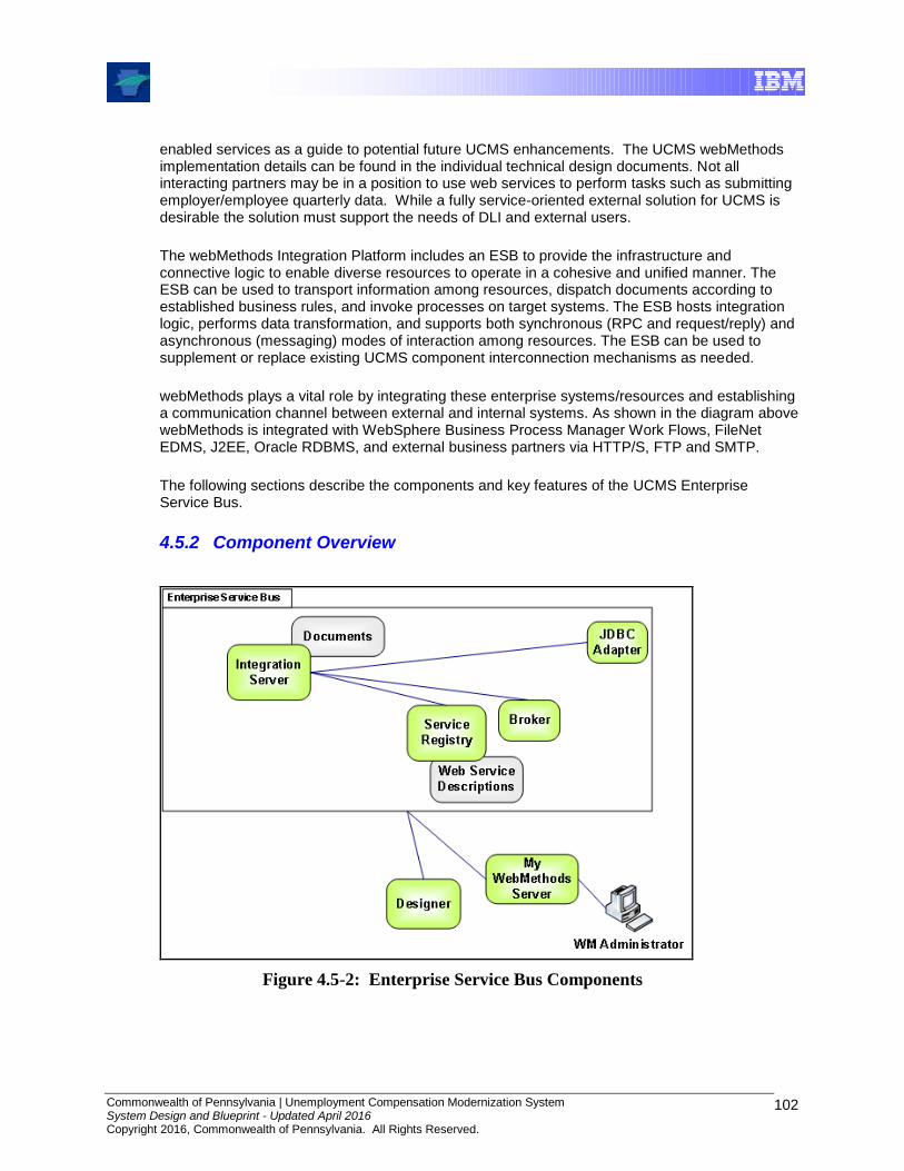
Commonwealth of Pennsylvania | Unemployment Compensation Modernization System System Design and Blueprint - Updated April 2016 Copyright 2016, Commonwealth of Pennsylvania. All Rights Reserved.
102
enabled services as a guide to potential future UCMS enhancements. The UCMS webMethods implementation details can be found in the individual technical design documents. Not all interacting partners may be in a position to use web services to perform tasks such as submitting employer/employee quarterly data. While a fully service-oriented external solution for UCMS is desirable the solution must support the needs of DLI and external users.
The webMethods Integration Platform includes an ESB to provide the infrastructure and connective logic to enable diverse resources to operate in a cohesive and unified manner. The ESB can be used to transport information among resources, dispatch documents according to established business rules, and invoke processes on target systems. The ESB hosts integration logic, performs data transformation, and supports both synchronous (RPC and request/reply) and asynchronous (messaging) modes of interaction among resources. The ESB can be used to supplement or replace existing UCMS component interconnection mechanisms as needed.
webMethods plays a vital role by integrating these enterprise systems/resources and establishing a communication channel between external and internal systems. As shown in the diagram above webMethods is integrated with WebSphere Business Process Manager Work Flows, FileNet EDMS, J2EE, Oracle RDBMS, and external business partners via HTTP/S, FTP and SMTP.
The following sections describe the components and key features of the UCMS Enterprise Service Bus.
4.5.2 Component Overview
Figure 4.5-2: Enterprise Service Bus Components

Commonwealth of Pennsylvania | Unemployment Compensation Modernization System System Design and Blueprint - Updated April 2016 Copyright 2016, Commonwealth of Pennsylvania. All Rights Reserved.
103
4.5.2.1 Run-Time
This section describes the webMethods run-time components.
4.5.2.1.1 Integration Server webMethods Integration Server is the central run-time component and the primary engine for the execution of integration logic. It is the main entry point for the systems and applications that can be integrated. It also connects internal and external resources to the integration backbone.
4.5.2.1.2 Broker webMethods Broker is a high-speed message router. It is the primary component of what is generally referred to as the “message backbone” or “message facility.” Along with supporting features provided by the other components, webMethods Broker facilitates asynchronous, message-based solutions using the publish-and-subscribe model. The role of a Broker is to route documents between information producers (publishers) and information consumers (subscribers).
4.5.2.1.3 Adapters An adapter exposes the data and business logic associated with a particular back-end resource to the Integration Server. An adapter incorporates a resource into an integration solution without having to build complex custom code or understand the low-level details of the resource or its transport protocol(s). The adapter handles the low-level work of connecting to the resource, managing communications, encoding and decoding data, and invoking processes. Adapters can also perform protocol translation if necessary. UCMS uses JDBC and MQ adapters..
4.5.2.2 Design-Time
webMethods provides tools for developing and testing integration solutions.
Designer is the graphical development tool that is used to build, edit, and test integration logic. It provides an integrated development environment in which to develop the logic and supporting elements that carry out the work of an integration solution like UCMS. It also provides tools for testing and debugging the solutions that are created.
4.5.2.3 Administration and Monitoring
Administration and monitoring components are installed, configured, and used by DLI and/or OIT personnel. The tools include myWebMethods (a Web-based, administration and monitoring user interface for managing webMethods components), and other tools. UCMS uses the monitoring tools to view status information about the process, services, and documents to perform tasks. The tools have user interfaces, and in some situations, also have the ability to notify key personnel via email, mobile and text messages. Tools such as webMethods Manager can communicate with the system management console (Tivoli) through the OMI specification, which defines the standard way of accessing and managing the integration platform components and the associated business processes.
Please refer to Section 8.0, Systems Management Architecture, for more information regarding Tivoli.

Commonwealth of Pennsylvania | Unemployment Compensation Modernization System System Design and Blueprint - Updated April 2016 Copyright 2016, Commonwealth of Pennsylvania. All Rights Reserved.
104
4.5.3 Key Concepts, Features and Capabilities
4.5.3.1 Integration
This section describes concepts such as documents and services, features such as assured delivery, and capabilities such as the exchange of documents with business partners.
4.5.3.1.1 Services Services embody the processes and the logic for business tasks. A service can be connected to a resource, retrieve data from a resource, transform the data or message into another format and route the results to the consumers via Broker or by invoking processes for the target resource.
UCMS services utilize the webMethods supplied pre-packaged bundle and also custom development when a particular interface or process was not provided by webMethods.
4.5.3.1.2 Documents A webMethods “document” represents the body of data that a resource passes to webMethods components (or vice versa) and does not necessarily imply an actual document or file. Documents may be the outcome of a business event such as filing a tax return (a tax return document might contain fields such as SSN, YTD) or adding a new employer (a new employer document might contain fields such as SSN, Last Name, First Name).
The UCMS ESB handles various types of (actual) documents such as XML, EDI, WSDL, SAP (IDocs), and flat file data produced by or consumed by external business partners and internal enterprise systems. The received documents are converted to an internal format that webMethods components act upon (and as noted above, are still referred to as a “document”). A document remains in this internal format as it travels through the integration backbone (for example, from Integration Server to Broker). If the document has to be sent to a particular back-end application or system, it is then converted to a native format by the adapter or to the format which the application or system understands.
4.5.3.1.3 Web Services ESB decoupled services are made available as a web services allowing service consumers to be connected to service providers in a protocol-independent manner, and as a result both can be unaware of the other (i.e., no connection-by-connection code changes are needed to support information exchanges). This benefits both internal connections within an enterprise and external connections to business partners
As a Web service provider, webMethods can also expose any of its own services as a Web service. This simple but powerful capability extends the existing data and logic of the back-end resources to any Web service-compliant client inside or outside the enterprise. As a Web service consumer, webMethods can invoke a Web service anywhere on the Internet or intranet.
UCMS maintains a Universal Description And Discovery Interface (UDDI)-based registry catalog that can be interrogated in real-time to determine the WSDL, endpoint, and specific attributes of the requested service, and to perform the necessary bindings between the service consumer and caller. However, it is also possible to “hard-wire” services to connect to endpoints, without a registry. While not as flexible as using a registry, and more difficult to maintain, this approach usually results in higher performance.
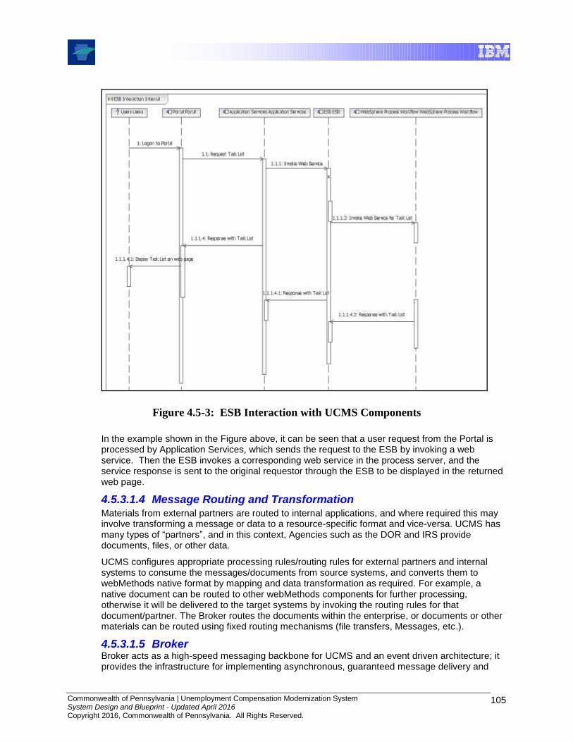
Commonwealth of Pennsylvania | Unemployment Compensation Modernization System System Design and Blueprint - Updated April 2016 Copyright 2016, Commonwealth of Pennsylvania. All Rights Reserved.
105
Figure 4.5-3: ESB Interaction with UCMS Components
In the example shown in the Figure above, it can be seen that a user request from the Portal is processed by Application Services, which sends the request to the ESB by invoking a web service. Then the ESB invokes a corresponding web service in the process server, and the service response is sent to the original requestor through the ESB to be displayed in the returned web page.
4.5.3.1.4 Message Routing and Transformation Materials from external partners are routed to internal applications, and where required this may involve transforming a message or data to a resource-specific format and vice-versa. UCMS has many types of “partners”, and in this context, Agencies such as the DOR and IRS provide documents, files, or other data.
UCMS configures appropriate processing rules/routing rules for external partners and internal systems to consume the messages/documents from source systems, and converts them to webMethods native format by mapping and data transformation as required. For example, a native document can be routed to other webMethods components for further processing, otherwise it will be delivered to the target systems by invoking the routing rules for that document/partner. The Broker routes the documents within the enterprise, or documents or other materials can be routed using fixed routing mechanisms (file transfers, Messages, etc.).
4.5.3.1.5 Broker Broker acts as a high-speed messaging backbone for UCMS and an event driven architecture; it provides the infrastructure for implementing asynchronous, guaranteed message delivery and

Commonwealth of Pennsylvania | Unemployment Compensation Modernization System System Design and Blueprint - Updated April 2016 Copyright 2016, Commonwealth of Pennsylvania. All Rights Reserved.
106
routing in a highly efficient, decoupled and scalable architecture for message-based solutions that are built on the publish-and-subscribe model or one of its variants, request/reply or publish-and-wait. The guaranteed-delivery feature of the Broker ensures one-time delivery of document to the subscriber. If the subscriber is not available the document is put in the queue and delivered when the subscriber(s) resume.
4.5.3.1.6 Assured Delivery All critical interfaces in the ESB use the Guaranteed Delivery facility of Integration Server, which ensures guaranteed, one-time execution of services. Guaranteed Delivery protects transactional requests from transient failures that might occur on the network, in the client, or on the server.
4.5.3.1.7 Supported Protocols The UCMS ESB supports multiple protocols to move the data across networks, whether they are Internet, private networks, or local and wide area network (LANs and WANs). The standards in use at this level provide transport interoperability between servers, desktops, routers, and other components, for data traffic, files and other network traffic. Protocols such as HTTP/HTTPS, FTP/FTPS, SMTP (email), JMS and SOAP are popular industry standard transport layers for secure/non-secure data transfers.
4.5.3.1.8 Built-in Adapters and Custom Adapters UCMS uses the ESB to communicate with the DLI Enterprise systems. The ESB built-in adapters are capable of exposing data and business logic to any enterprise system. Custom adapters, built using product specific APIs using languages including Java, C, and C++, are built for resources which don’t have built-in adapters. The following adapters are used
JDBC Adapter for any RDBMS (Sybase, DB2, MS SQL Server, Oracle)
WebSphere MQ Adapter for Message Queue
4.5.3.1.9 Exchange of Documents with Business Partners UCMS supports a set of organizations that have agreed to exchange business documents with DLI. This provides document persistence (inbound and outbound), partner validation, scheduled or batch delivery and secure communication using SSL.
Interactions can occur, for example, when documents are FTP’d to UCMS, and then routed (via the ESB) and made available to FileNet for further processing, which, in this scenario, returns a Document ID.
4.5.3.1.10 Security UCMS ESB provides security protections for access control, authentication and data privacy including encryption for confidentiality and digital signatures for data integrity. UserID and Password authentication are used for interaction with DLI enterprise back end systems.
Access Control: Access Control Lists are created on the Integration Server, limiting requests to specified addresses or domains. It also restricts which resources are accessible through an individual port.
Authentication: UCMS uses standard user name/password authentication over HTTP, HTTPS, FTP and e-mail connections with external partners. Partner identity is authenticated against SiteMinder IAM credentials.
Data Privacy: The ESB communicates with external partners using secure sockets layer (SSL) and data encryption. By adding Digital Signatures to the data sent out and, verifying those signatures at the receiving server using industry standard digital signatures based on S/MIME, it is possible to prove that a given document originated from a particular computer or user.

Commonwealth of Pennsylvania | Unemployment Compensation Modernization System System Design and Blueprint - Updated April 2016 Copyright 2016, Commonwealth of Pennsylvania. All Rights Reserved.
107
4.5.3.1.11 Scalability UCMS uses high capacity servers to run the Integration and Broker servers in a clustered configuration, thus increasing throughput and improving performance by distributing requests among a group of servers. The Integration Server cluster provides automatic redirection of inbound requests when servers reach a defined capacity threshold. This ensures even distribution of processing in high volume data exchanges situations. A third party load balancer can be used to redirect requests to Integration Server.
4.6 Business Rules
4.6.1 Introduction
WebSphere
BPM
BO Ent
DB
Universes
Enterprise Service Bus
Documents
WAS
Web Service
Descriptions
Oracle
Integration
Server
JDBC
Adapter
Content
Engine
Content
Collector
LiveCycle
Forms
Service
Registry
JDBC
Portal
IIS Web
Server
Web Server
Form Services
Portal Services
Application Services
Actions
Corticon
Server
Rule Set
Domain
Object
JMS
Business
Process
OLTP
Database
Service Component
Service
Java Client
Systems Management
Tivoli Enterprise
Monitoring
(TEMS)
WebSphere
Data Stage
Local Data Services
WebSphere
Application
Server
FileNet
DB
Reporting Services
Tivoli Ent
Portal (TEP)Tivoli Data
Warehouse
ITCAM for AD
Document Services
Form
Templates
Broker
Automation
Service
Portal
Search
Portal
DB
Audit DB
Mobile
Sync
Oracle
JSPs
LiveCycle
Designer
Capture
Desktop
Image
Files
Application
Engine
BO
Portlet
Reports
UCMS
PortletSiteMinder
Policy
Server
Workflow
Server
Identity
Minder
Server
Security Services
Business
Flow
Human
Task
Service
Service Component
WAS
Workflow Services
CBE
State
Machine
Tivoli
Omnibus
Tivoli
Netview
Console
Mobile
Server
Business-
Objects
Enterprise
Mobile
DB
B
`
Browser
Client
`
Low-Volume
Scan Station
Service
Now
B
WAS DBCBE
Persist
Fmwk
C
C
Auth
Sync
Service
Caching
Config
FmwkCaching
Fmwk
Exception
Handling
Logging
FmwkCaching
Fmwk
Portal
Fmwk
MVC
Fmwk
Messaging
Fmwk
Web App
Fmwk
Data
AccessActive
Directory
Portal
Identity
Service
Reporting
Database
Oracle
SiteMinder
Agent
SiteMinder
API
Security
Fmwk
`
Business Analyst
Corticon
Rules
Studio Corticon
Collaborator
Rule Set
Figure 4.6-1: Business Rules Context
UCMS is largely rule-driven, with most of the rules derived from laws, regulations, policy, and common accounting principles. Corticon Business Rules Management provides a complete self-contained rule-modeling development environment that deploys rules to the rules server. Corticon addresses user friendliness and performance issues associated with rules management. For UCMS, Corticon is used for both application-based and workflow-based rules processing.
The following sections describe the components and key features of Corticon Business Rules Management.
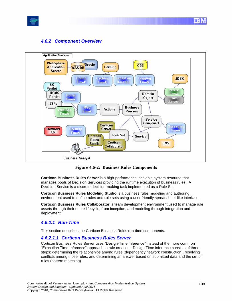
Commonwealth of Pennsylvania | Unemployment Compensation Modernization System System Design and Blueprint - Updated April 2016 Copyright 2016, Commonwealth of Pennsylvania. All Rights Reserved.
108
4.6.2 Component Overview
Figure 4.6-2: Business Rules Components
Corticon Business Rules Server is a high-performance, scalable system resource that manages pools of Decision Services providing the runtime execution of business rules. A Decision Service is a discrete decision-making task implemented as a Rule Set.
Corticon Business Rules Modeling Studio is a business rules modeling and authoring environment used to define rules and rule sets using a user friendly spreadsheet-like interface.
Corticon Business Rules Collaborator is team development environment used to manage rule assets through their entire lifecycle; from inception, and modeling through integration and deployment.
4.6.2.1 Run-Time
This section describes the Corticon Business Rules run-time components.
4.6.2.1.1 Corticon Business Rules Server Corticon Business Rules Server uses “Design-Time Inference” instead of the more common “Execution Time Inference” approach to rule creation. Design Time inference consists of three steps: determining the relationships among rules (dependency network construction), resolving conflicts among those rules, and determining an answer based on submitted data and the set of rules (pattern matching)
Commonwealth of Pennsylvania | Unemployment Compensation Modernization System System Design and Blueprint - Updated April 2016 Copyright 2016, Commonwealth of Pennsylvania. All Rights Reserved.
109
Execution Time Inference rules systems are based on the RETE5 algorithm. They perform all three of the Rules inference steps each time a decision is made, at run-time. While this works well in expert systems, it can be inefficient in high volume discrete decision making situations.
Design Time Inference performs the first two steps one time, when the rule set is compiled. When a decision needs to be made at runtime the only step required is the pattern matching. This makes it faster and more efficient than many RETE-based systems, although RETE systems have since reduced the performance differences by implementing hybrid rule processing.
The Rules Server is deployed to a J2EE Application Server where it is accessed by application functions and workflows. Due to the optimized nature of the generated rule sets, the Corticon Rules Server scales well as usage increases. The Corticon Rules Server has been benchmarked to execute millions of decisions per day, and scales linearly with increased hardware processing power.
The Corticon Server component executes individual Decision Services, which were developed as Rule Sets using the Corticon Business Rules Modeling Studio. The Rules Server is based on industry and open standards, such as J2EE and XML. It has near-real-time hot deployment of rules from Corticon Studio. Decision Services are performed using standard SOAP-based Web services or using Java API method calls.
4.6.2.2 Design-Time
This section describes the Corticon Business Rules design-time components.
4.6.2.2.1 Corticon Business Rules Modeling Studio Corticon Business Rules Modeling Studio is a business rules modeling and authoring environment. It is uses a spreadsheet-like interface that is easy for non-technical staff to work with. It also provides significant quality assurance advances, checking for rule collisions and logical holes at design time, rather than requiring labor-intensive testing later in the design/deploy/deliver life cycle.
The Corticon Studio rules creation tool allows business users to create rule services, and perform rule testing. Corticon Studio provides a spreadsheet-like user interface, allowing users to create rule conditions using drag-and-drop functionality, utilizing a library of pre-defined functions. Users can visualize the complete rule set in the Studio tool, unlike rules engines which construct complete rules only at execution time. This approach helps to ensure no gaps exist in business rules, something which can’t be done at run-time using some other rules management products, although most tools have improved their design-time visualization and testing capabilities since the time that Corticon was selected and implemented for UCMS.
5 RETE, usually pronounced either 'REET', 'REE-tee' or, in Europe, 're-tay' after the Latin pronunciation, is derived from the Latin 'rete' for net, or network.

Commonwealth of Pennsylvania | Unemployment Compensation Modernization System System Design and Blueprint - Updated April 2016 Copyright 2016, Commonwealth of Pennsylvania. All Rights Reserved.
110
Figure 4.6-3: Corticon Business Rules Modeling Studio
4.6.2.2.2 Corticon Business Rules Collaborator Corticon Business Rules Collaborator (BRC) is a team development environment used to manage rule assets throughout their lifecycle; from inception and modeling to integration and deployment. BRC provides the critical capabilities needed to control business rules development such as rules version and access management, workflows for rule approval processes, and rule change impact analysis. It is a web-based solution enabling project teams to work together, facilitating interactions, managing rule-project assets, and driving tasks to completion.
4.6.2.3 Administrative and Monitoring
4.6.2.3.1 Deploying Rules as Decision Services
Rules are organized into Rules Sets. Rule Sets are deployed to the Corticon Business Rules Server as Decision Services. The deployment of these services is accomplished through the Corticon Deployment Console utility that comes with the Corticon Business Rules Server. Decision Services are exported from the Corticon Business Rules Modeling Studio as a “.ccj” file. This file is then placed on the Web Application Server that is hosting the Corticon Business Rules Server. The Corticon Deployment Console creates deployment descriptors as “.ccd” files. These files provide all of the configuration information needed by the Corticon Business Rules Server to make the Decision Service available to be performed.
Commonwealth of Pennsylvania | Unemployment Compensation Modernization System System Design and Blueprint - Updated April 2016 Copyright 2016, Commonwealth of Pennsylvania. All Rights Reserved.
111
4.6.3 Key Concepts, Features and Capabilities
4.6.3.1 Vocabulary
The Vocabulary provides the basic elements of the rule language, the building blocks with which business rules are implemented in Corticon Business Rules Modeling Studio. It is an abstracted version of a data model that contains the objects used in the business rules. It provides terms that represent business “things” such as entities and attributes that are defined in terms of the specific business involved (for UCMS, they are defined in terms of Unemployment Compensation concepts). The Vocabulary can be manually created or loaded from a JDBC connection.
The Vocabulary provides a federated data model that consolidates entities and attributes from various enterprise data resources. It also provides a built-in library of literal terms and operators that can be applied to entities or attributes in the Vocabulary when constructing a rule.
The Vocabulary is used to define a schema for sending and receiving data from a Corticon Decision Service. Since XML messaging is used to carry data to and from the rules for evaluation, data must be organized in a pre-defined structure (called a schema) that can be understood and processed by the rules engine. An XML schema that accomplishes this purpose can be automatically generated directly from the Vocabulary.
4.6.3.2 Business Rule
Business Rules are used to create and change critical business decision logic quickly and reliably without altering software code. Business Rules are organized as Rules, Rule Sheets and Rule Sets. These facilitate separation of concerns and service re-use. A Vocabulary section is also used for XSD generation. Finally, rules are logically organized as granular rule decision services for appropriate consumption of the rules by external clients.
4.6.3.3 Rule Set
A Rule Set is the central, independent unit of automated decision-making. It is a set of one or more Rule Sheets that have been tested and validated using the Corticon Business Rules Modeling Studio. Following test and validation, a Rule Set may be deployed into a production environment.
Note: Once deployed and available to other IT systems, a Rule Set is referred to as a Decision Service.
4.6.3.4 Decision Services
A Decision Service is used to automate a discrete decision-making task. It is implemented as a set of business rules and exposed as a Web Service or a Java Service. Rules within a Decision Service are complete and unambiguous and for a given set of inputs, the Decision Service addresses every logical possibility uniquely, ensuring “decision integrity”.
Performing Decision Services
There are three options used to perform Decision Services running on the Corticon Business Rules Server. The specific option used depends on the capabilities of the consumer, desired level of decoupling and performance requirements.
Web Services offers the greatest degree of both flexibility and reuse. It uses the standards of Web Services (including XML, SOAP, HTTP, WSDL, and XSD), this choice offers the greatest degree of both flexibility and reuse. The Deployment Console (or Deployment Console API) is
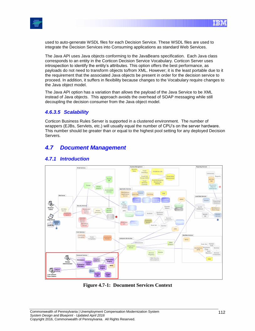
Commonwealth of Pennsylvania | Unemployment Compensation Modernization System System Design and Blueprint - Updated April 2016 Copyright 2016, Commonwealth of Pennsylvania. All Rights Reserved.
112
used to auto-generate WSDL files for each Decision Service. These WSDL files are used to integrate the Decision Services into Consuming applications as standard Web Services.
The Java API uses Java objects conforming to the JavaBeans specification. Each Java class corresponds to an entity in the Corticon Decision Service Vocabulary. Corticon Server uses introspection to identify the entity’s attributes. This option offers the best performance, as payloads do not need to transform objects to/from XML. However; it is the least portable due to it the requirement that the associated Java objects be present in order for the decision service to proceed. In addition, it suffers in flexibility because changes to the Vocabulary require changes to the Java object model.
The Java API option has a variation than allows the payload of the Java Service to be XML instead of Java objects. This approach avoids the overhead of SOAP messaging while still decoupling the decision consumer from the Java object model.
4.6.3.5 Scalability
Corticon Business Rules Server is supported in a clustered environment. The number of wrappers (EJBs, Servlets, etc.) will usually equal the number of CPU’s on the server hardware. This number should be greater than or equal to the highest pool setting for any deployed Decision Servers.
4.7 Document Management
4.7.1 Introduction
WebSphere
BPM
BO Ent
DB
Universes
Enterprise Service Bus
Documents
WAS
Web Service
Descriptions
Oracle
Integration
Server
JDBC
Adapter
Content
Engine
Content
Collector
LiveCycle
Forms
Service
Registry
JDBC
Portal
IIS Web
Server
Web Server
Form Services
Portal Services
Application Services
Actions
Corticon
Server
Rule Set
Domain
Object
JMS
Business
Process
OLTP
Database
Service Component
Service
Java Client
Systems Management
Tivoli Enterprise
Monitoring
(TEMS)
WebSphere
Data Stage
Local Data Services
WebSphere
Application
Server
FileNet
DB
Reporting Services
Tivoli Ent
Portal (TEP)Tivoli Data
Warehouse
ITCAM for AD
Document Services
Form
Templates
Broker
Automation
Service
Portal
Search
Portal
DB
Audit DB
Mobile
Sync
Oracle
JSPs
LiveCycle
Designer
Capture
Desktop
Image
Files
Application
Engine
BO
Portlet
Reports
UCMS
PortletSiteMinder
Policy
Server
Workflow
Server
Identity
Minder
Server
Security Services
Business
Flow
Human
Task
Service
Service Component
WAS
Workflow Services
CBE
State
Machine
Tivoli
Omnibus
Tivoli
Netview
Console
Mobile
Server
Business-
Objects
Enterprise
Mobile
DB
B
`
Browser
Client
`
Low-Volume
Scan Station
Service
Now
B
WAS DBCBE
Persist
Fmwk
C
C
Auth
Sync
Service
Caching
Config
FmwkCaching
Fmwk
Exception
Handling
Logging
FmwkCaching
Fmwk
Portal
Fmwk
MVC
Fmwk
Messaging
Fmwk
Web App
Fmwk
Data
Access
Rule Set
Active
Directory
Portal
Identity
Service
Reporting
Database
Oracle
SiteMinder
Agent
SiteMinder
API
Security
Fmwk
`
FileNet
Administrator
Workplace
Content
AdminEnterprise
Manager
Figure 4.7-1: Document Services Context
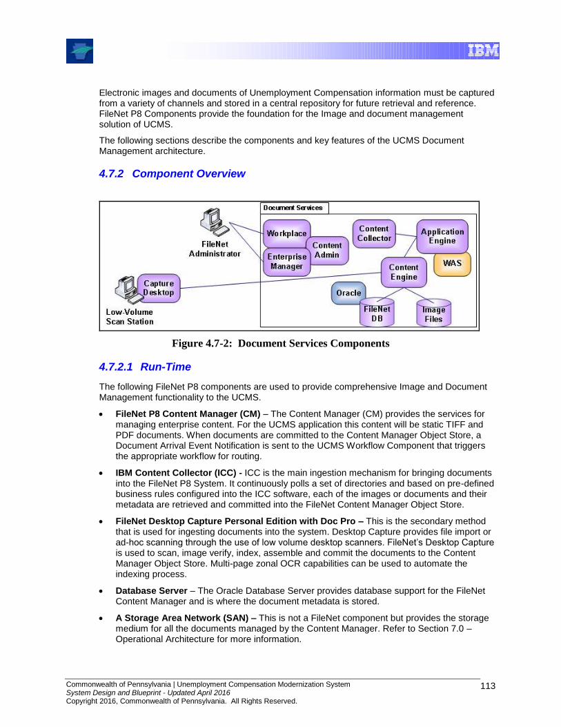
Commonwealth of Pennsylvania | Unemployment Compensation Modernization System System Design and Blueprint - Updated April 2016 Copyright 2016, Commonwealth of Pennsylvania. All Rights Reserved.
113
Electronic images and documents of Unemployment Compensation information must be captured from a variety of channels and stored in a central repository for future retrieval and reference. FileNet P8 Components provide the foundation for the Image and document management solution of UCMS.
The following sections describe the components and key features of the UCMS Document Management architecture.
4.7.2 Component Overview
Figure 4.7-2: Document Services Components
4.7.2.1 Run-Time
The following FileNet P8 components are used to provide comprehensive Image and Document Management functionality to the UCMS.
FileNet P8 Content Manager (CM) – The Content Manager (CM) provides the services for managing enterprise content. For the UCMS application this content will be static TIFF and PDF documents. When documents are committed to the Content Manager Object Store, a Document Arrival Event Notification is sent to the UCMS Workflow Component that triggers the appropriate workflow for routing.
IBM Content Collector (ICC) - ICC is the main ingestion mechanism for bringing documents into the FileNet P8 System. It continuously polls a set of directories and based on pre-defined business rules configured into the ICC software, each of the images or documents and their metadata are retrieved and committed into the FileNet Content Manager Object Store.
FileNet Desktop Capture Personal Edition with Doc Pro – This is the secondary method that is used for ingesting documents into the system. Desktop Capture provides file import or ad-hoc scanning through the use of low volume desktop scanners. FileNet’s Desktop Capture is used to scan, image verify, index, assemble and commit the documents to the Content Manager Object Store. Multi-page zonal OCR capabilities can be used to automate the indexing process.
Database Server – The Oracle Database Server provides database support for the FileNet Content Manager and is where the document metadata is stored.
A Storage Area Network (SAN) – This is not a FileNet component but provides the storage medium for all the documents managed by the Content Manager. Refer to Section 7.0 – Operational Architecture for more information.

Commonwealth of Pennsylvania | Unemployment Compensation Modernization System System Design and Blueprint - Updated April 2016 Copyright 2016, Commonwealth of Pennsylvania. All Rights Reserved.
114
4.7.2.2 Design-Time
The Content Java APIs and the Content Engine Web Services are used to create the necessary Document Service Components. This provides each of the UCMS applications, as needed, with the ability to query and retrieve documents and images, update a document’s or image’s metadata, and provide the ability to add and maintain image annotations. The UCMS applications communicate to the ESB through the UCMS Framework components to invoke the appropriate Document Service Component to communicate with the FileNet Content Manager.
The Content Java API provides networked, Java-based access to commonly-used objects and methods within the COM API. The Content Java API consists of Java-based and COM-based logical architectural subcomponents, and the transport between them.
The Java-based components are platform-neutral and generally provide a thin wrapping around remote procedure calls. They perform the marshalling and un-marshalling of parameters for serialization and deserialization. For specific objects, they can also provide limited, transparent, caching of object property values.
The Content Engine Web Service (CEWS) is an industry standards-conformant SOAP interface to the P8 Content Engine. It allows applications to access most of the functionality available through the Content Engine COM API. CEWS provides general-purpose SOAP operations (methods) and elements that expose all of the Content Engine objects and most of their properties and methods.
4.7.2.3 Administrative and Monitoring
There are many tools which are used to administer and monitor the various FileNet components:
FileNet Application Engine (AE) - The Application Engine (AE) is the presentation layer for FileNet P8 Content Manager and provides some administrative functionality to the Content Manager via a web interface called Workplace. Objectstore configuration options can be set through Workplace.
FileNet Enterprise Manager -FileNet Content Manager is also administered and configured using this Windows Manager snap-in tool. FileNet Enterprise Manager provides the capabilities to create all of the objects necessary for document management including objectstores, document classes, document properties or indexes, event action scripts, and filestore configurations.
ICC Manager - ICC is administered and configured using this interface that resides on the ICC Server. This tool assists the user in creating the business rules to identify and index documents and images, identify network locations to monitor, set monitoring time interval configurations and configure Objectstore document storage locations.
Desktop Capture Manager- FileNet Desktop Capture is administered through this component that is part of the FileNet Desktop Capture Software. Configuration is done through the FileNet Desktop Capture software to set up pre-set scanning, indexing and processing settings for each of the different type of documents that are scanned. Statistics logging can be used to monitor the productivity and volumes of documents scanned at each workstation.
While monitoring of events occurs using monitoring tools available with FileNet, critical alerts are forwarded to Tivoli Omnibus for review and possible follow-up, e.g., creation of DLI ServiceNow Ticket. Please refer to Section 8.0, Systems Management Architecture, for more information.
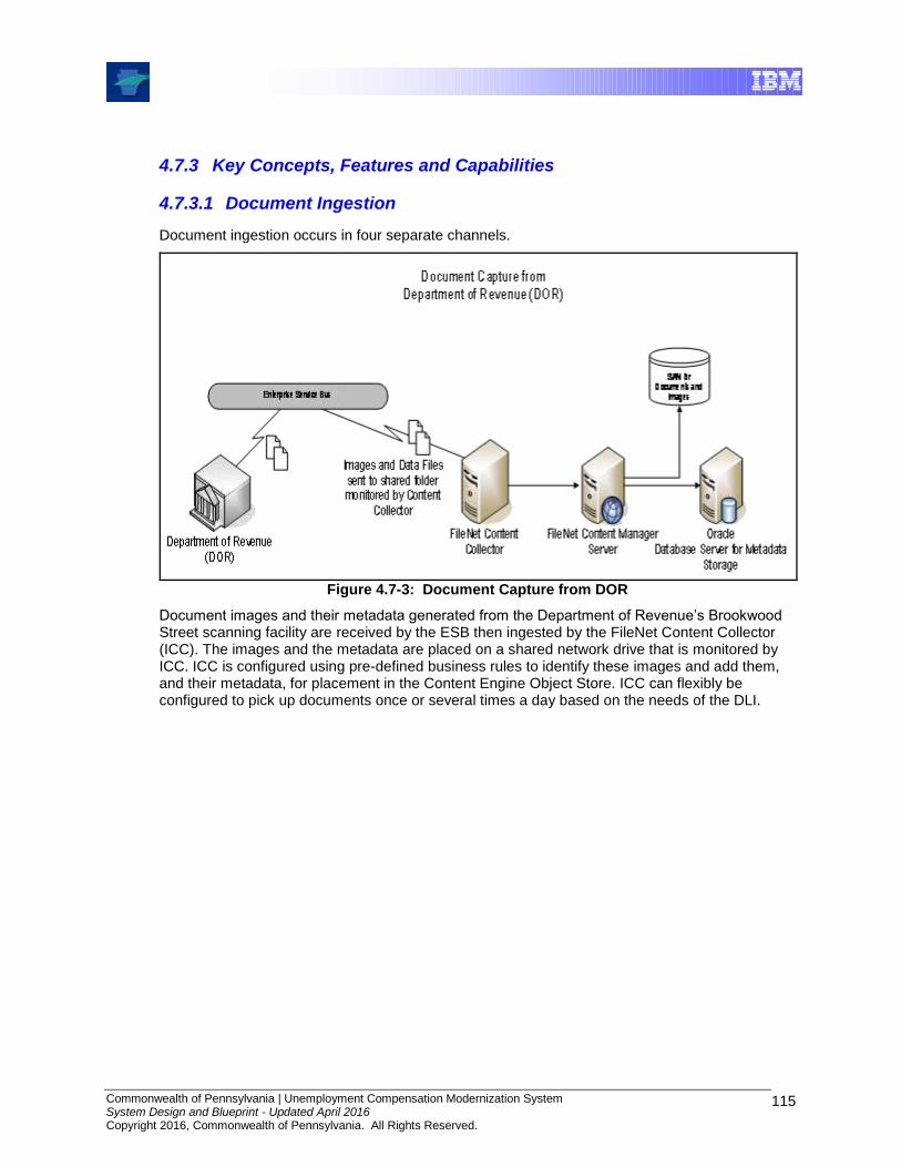
Commonwealth of Pennsylvania | Unemployment Compensation Modernization System System Design and Blueprint - Updated April 2016 Copyright 2016, Commonwealth of Pennsylvania. All Rights Reserved.
115
4.7.3 Key Concepts, Features and Capabilities
4.7.3.1 Document Ingestion
Document ingestion occurs in four separate channels.
Figure 4.7-3: Document Capture from DOR
Document images and their metadata generated from the Department of Revenue’s Brookwood Street scanning facility are received by the ESB then ingested by the FileNet Content Collector (ICC). The images and the metadata are placed on a shared network drive that is monitored by ICC. ICC is configured using pre-defined business rules to identify these images and add them, and their metadata, for placement in the Content Engine Object Store. ICC can flexibly be configured to pick up documents once or several times a day based on the needs of the DLI.
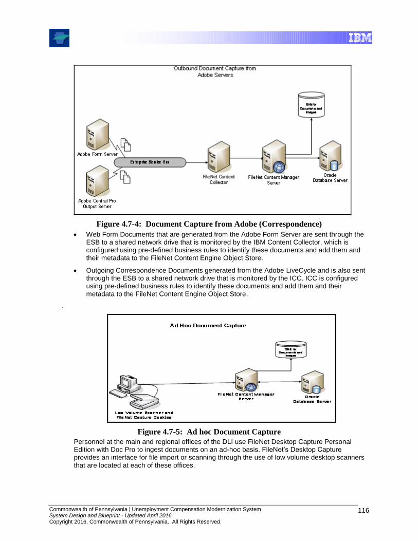
Commonwealth of Pennsylvania | Unemployment Compensation Modernization System System Design and Blueprint - Updated April 2016 Copyright 2016, Commonwealth of Pennsylvania. All Rights Reserved.
116
Figure 4.7-4: Document Capture from Adobe (Correspondence)
Web Form Documents that are generated from the Adobe Form Server are sent through the ESB to a shared network drive that is monitored by the IBM Content Collector, which is configured using pre-defined business rules to identify these documents and add them and their metadata to the FileNet Content Engine Object Store.
Outgoing Correspondence Documents generated from the Adobe LiveCycle and is also sent through the ESB to a shared network drive that is monitored by the ICC. ICC is configured using pre-defined business rules to identify these documents and add them and their metadata to the FileNet Content Engine Object Store.
.
Figure 4.7-5: Ad hoc Document Capture
Personnel at the main and regional offices of the DLI use FileNet Desktop Capture Personal Edition with Doc Pro to ingest documents on an ad-hoc basis. FileNet’s Desktop Capture provides an interface for file import or scanning through the use of low volume desktop scanners that are located at each of these offices.

Commonwealth of Pennsylvania | Unemployment Compensation Modernization System System Design and Blueprint - Updated April 2016 Copyright 2016, Commonwealth of Pennsylvania. All Rights Reserved.
117
4.7.3.2 Document Retrieval
The Content Java APIs and the Content Engine Web Services are used to create the necessary Document Service Components that provide the ability to search and retrieve the documents and images in the FileNet Content Manager Object Store. The retrieved documents or images are displayed via the Web browser using the appropriate plug-in or applet based on MIME type.
4.7.3.3 Security
FileNet is protected from unauthorized access using authentication and authorization control mechanisms as well as network and operating system controls. The authentication and authorization is performed by SiteMinder when the user initially enters the Portals. Access to FileNet is controlled at the Portlet level based upon the user’s SiteMinder role. Users invoke FileNet through a service account from the Portal. Therefore, all security decisions for the users are determined prior to accessing FileNet. FileNet uses native application security mechanisms to authenticate and authorize the service accounts accessing FileNet.
In addition, the network and host infrastructure supporting the applications are controlled through access control lists and operating system controls to limit access only to authorized objects.
4.7.3.4 Scalability
Application Engine (AE) - Scales by adding additional servers (AEs) to the AE server farm.
Content Engine – In order to scale the Content Engine (CE) the following would have to be done:
One component of the Content Engine, the File Store Service, can be moved to a separate and dedicated server (note – For High Availability purposes this should be an Active/Passive cluster). This is because the File Store Service is NOT farmable.
Take the existing Content Engine (CE) cluster and turn it into a server farm with a load balancer in front.
CE capacity can then be met by adding addition servers to the CE server farm.
IBM Content Collector – This is scaled by adding additional ICC servers. Since this is not a farmable server, each ICC polls a separate set of directories. For example, one polls a directory in which the Correspondence documents are dropped while another polls the directory where the DOR images are dropped.
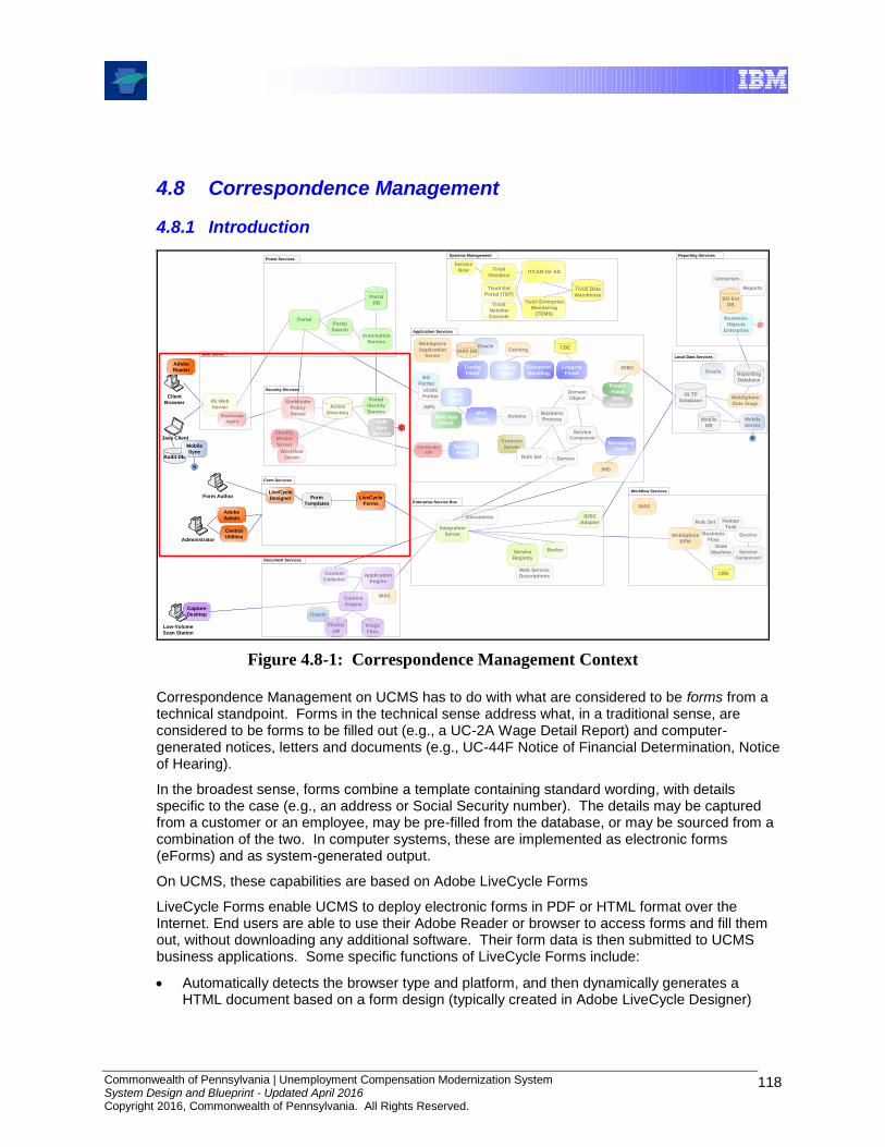
Commonwealth of Pennsylvania | Unemployment Compensation Modernization System System Design and Blueprint - Updated April 2016 Copyright 2016, Commonwealth of Pennsylvania. All Rights Reserved.
118
4.8 Correspondence Management
4.8.1 Introduction
WebSphere
BPM
BO Ent
DB
Universes
Enterprise Service Bus
Documents
WAS
Web Service
Descriptions
Oracle
Integration
Server
JDBC
Adapter
Content
Engine
Content
Collector
LiveCycle
Forms
Service
Registry
JDBC
Portal
IIS Web
Server
Web Server
Form Services
Portal Services
Application Services
Actions
Corticon
Server
Rule Set
Domain
Object
JMS
Business
Process
OLTP
Database
Service Component
Service
Java Client
Systems Management
Tivoli Enterprise
Monitoring
(TEMS)
WebSphere
Data Stage
Local Data Services
WebSphere
Application
Server
FileNet
DB
Reporting Services
Tivoli Ent
Portal (TEP)Tivoli Data
Warehouse
ITCAM for AD
Document Services
Form
Templates
Broker
Automation
Service
Portal
Search
Portal
DB
Audit DB
Mobile
Sync
Oracle
JSPs
LiveCycle
Designer
Capture
Desktop
Image
Files
Application
Engine
BO
Portlet
Reports
UCMS
PortletSiteMinder
Policy
Server
Workflow
Server
Identity
Minder
Server
Security Services
Business
Flow
Human
Task
Service
Service Component
WAS
Workflow Services
CBE
State
Machine
Tivoli
Omnibus
Tivoli
Netview
Console
Mobile
Server
Business-
Objects
Enterprise
Mobile
DB
B
`
Client
Browser
`
Low-Volume
Scan Station
Service
Now
B
WAS DBCBE
Persist
Fmwk
C
C
Auth
Sync
Service
Caching
Config
FmwkCaching
Fmwk
Exception
Handling
Logging
FmwkCaching
Fmwk
Portal
Fmwk
MVC
Fmwk
Messaging
Fmwk
Web App
Fmwk
Data
Access
Rule Set
Active
Directory
Portal
Identity
Service
Reporting
Database
Oracle
SiteMinder
Agent
SiteMinder
API
Security
Fmwk
Adobe
Admin
Central
Utilities
`
Administrator
`
Form Author
Adobe
Reader
Figure 4.8-1: Correspondence Management Context
Correspondence Management on UCMS has to do with what are considered to be forms from a technical standpoint. Forms in the technical sense address what, in a traditional sense, are considered to be forms to be filled out (e.g., a UC-2A Wage Detail Report) and computer-generated notices, letters and documents (e.g., UC-44F Notice of Financial Determination, Notice of Hearing).
In the broadest sense, forms combine a template containing standard wording, with details specific to the case (e.g., an address or Social Security number). The details may be captured from a customer or an employee, may be pre-filled from the database, or may be sourced from a combination of the two. In computer systems, these are implemented as electronic forms (eForms) and as system-generated output.
On UCMS, these capabilities are based on Adobe LiveCycle Forms
LiveCycle Forms enable UCMS to deploy electronic forms in PDF or HTML format over the Internet. End users are able to use their Adobe Reader or browser to access forms and fill them out, without downloading any additional software. Their form data is then submitted to UCMS business applications. Some specific functions of LiveCycle Forms include:
Automatically detects the browser type and platform, and then dynamically generates a HTML document based on a form design (typically created in Adobe LiveCycle Designer)

Commonwealth of Pennsylvania | Unemployment Compensation Modernization System System Design and Blueprint - Updated April 2016 Copyright 2016, Commonwealth of Pennsylvania. All Rights Reserved.
119
For dynamic subforms, adds extra fields and boilerplate as a result of merging the form design with data or as a result of scripting
Validates data entry by performing calculations, accessing databases, or enforcing business rules on field-level data, and then returns the resulting data to the browser
Extracts submitted form data as XML
LiveCycle Forms also function as a PDF rendering engine for UCMS line-of-business applications. For instance, it could be used to create a hearing notice for a custom hearing scheduling function.
Adobe LiveCycle is used to implement the generation and distribution of high-volume outbound correspondence, forms and notices.
LiveCycle supports many aspects of document output from high-volume distributed printing to PDF generation for Web delivery, and offers multiple language and platform support. Some highlights include:
Generates dynamic output that grows or shrinks as necessary to accommodate the amount of data
Supports a wide variety of input formats, including XML, plain text, legacy, and DAT
Supports printer features such as duplexing, tray selection, flash RAM, and hard disks
Reduces network traffic because Output Server data stream contains data elements only
Supports multiple languages and currencies
Supports fax and e-mail delivery of documents
Performs data stream calculations
The following sections describe the components and key features of the UCMS Correspondence Management architecture.
4.8.2 Component Overview
LiveCycle
Forms
Form Services
Form
Templates
LiveCycle
Designer
Adobe
Admin
`
Administrator
`
Form Author
Figure 4.8-2: Correspondance Management Components
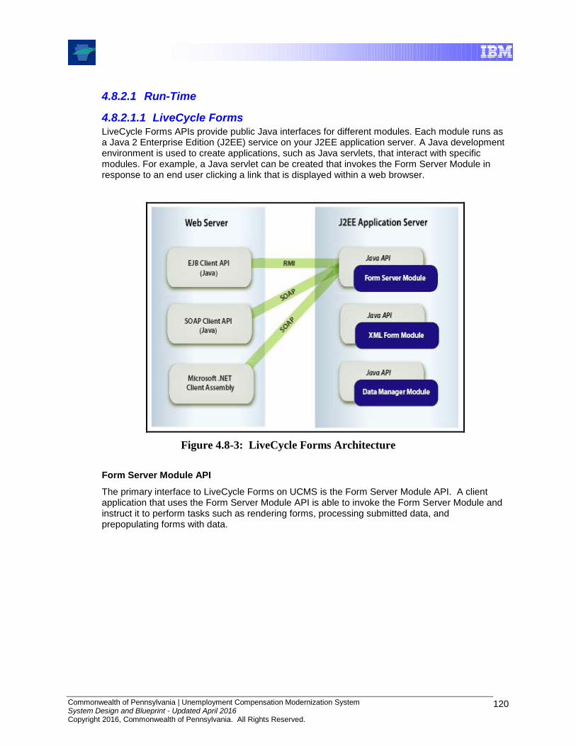
Commonwealth of Pennsylvania | Unemployment Compensation Modernization System System Design and Blueprint - Updated April 2016 Copyright 2016, Commonwealth of Pennsylvania. All Rights Reserved.
120
4.8.2.1 Run-Time
4.8.2.1.1 LiveCycle Forms LiveCycle Forms APIs provide public Java interfaces for different modules. Each module runs as a Java 2 Enterprise Edition (J2EE) service on your J2EE application server. A Java development environment is used to create applications, such as Java servlets, that interact with specific modules. For example, a Java servlet can be created that invokes the Form Server Module in response to an end user clicking a link that is displayed within a web browser.
Figure 4.8-3: LiveCycle Forms Architecture
Form Server Module API
The primary interface to LiveCycle Forms on UCMS is the Form Server Module API. A client application that uses the Form Server Module API is able to invoke the Form Server Module and instruct it to perform tasks such as rendering forms, processing submitted data, and prepopulating forms with data.

Commonwealth of Pennsylvania | Unemployment Compensation Modernization System System Design and Blueprint - Updated April 2016 Copyright 2016, Commonwealth of Pennsylvania. All Rights Reserved.
121
Figure 4.8-4: Application Integration with Form Server Module
The Form Server Module sends forms across a network and renders them to client devices, such as web browsers.
A client application that uses the Form Server Module API is able to retrieve the data submitted with a form. For example, when a user fills in a form and submits it, a client application can retrieve the data that the user entered in the form’s fields. The client application can then process the data in a variety of ways, such as performing calculations, storing it in an enterprise database, or sending it to another application, such as an application that authorizes credit cards.
The Form Server Module can pre-populate a form prior to rendering it. Pre-populating a form involves inserting data into a form. For example, a client application can query data from a database and instruct the Form Server Module to insert the data into a form and then render the form. Once the form is rendered to a client web browser, the user is able to view the data in the displayed form.
Using the Form Server Module, different types of client applications can be created that interact with the Form Server Module, such as Java servlets or JSPs. The Form Server Module performs the following functions:
Provides server-side execution of the intelligence that is in the form design. The Form Server Module executes the validations and calculations included in the form design and returns the resulting data to the browser.
Detects whether form design scripts should run on the client or the server. For clients that support client-side scripting such as Internet Explorer 5.0 and later, an appropriate scripting model is loaded into the device so that the scripts can run directly on the client computer. For information about the properties and methods supported in each transformation, see the LiveCycle Designer Help.
Dynamically generates a PDF or an HTML document of the form design with or without data. An HTML form can deliver multipage forms page by page. In contrast, a PDF form delivers all the pages at once. In LiveCycle Designer, the form author can script the current page number in the form design. The Form Server Module can merge one page of data submitted at a time or merge only the single page into the form design.
Supports dynamic subforms created in LiveCycle Designer. Form Server Module adds extra fields and boilerplate as a result of merging the form design with data or as a result of scripting. In the case of HTML, the added subforms can grow to unlimited page lengths. In the case of PDF, the added subforms paginate at the page lengths specified in the form design.

Commonwealth of Pennsylvania | Unemployment Compensation Modernization System System Design and Blueprint - Updated April 2016 Copyright 2016, Commonwealth of Pennsylvania. All Rights Reserved.
122
Validates data entry by performing calculations, accessing databases, or enforcing business rules on field-level data.
Displays validation errors in different ways (split frame left, top, right, bottom; no frame left, top, right, bottom; or no UI). This is all done without maintaining any state on the server. The validation errors are also made available in the XML-based validation error document.
Maintains the state of any pass-through data that has been passed in by the application. Pass-through data is data that does not have corresponding fields on the form design being processed. The pass-through data is passed back to the calling application after the target device submits the data.
Figure 4.8-5: Pre-populating a Form
As mentioned above, the Form Server Module API can be used to create a client application capable of pre-populating a form. Consider a loan application. After data is submitted to a HandleData Java servlet, a confirmation form is rendered back to the web browser. This form contains data that the user entered into the loan application. It is in this way that UCMS custom applications use LiveCycle Forms as a PDF rendering engine.
Deployment Options
As shown in the LiveCycle Forms Architecture diagram above, the Form Server module can be invoked via RMI or SOAP protocols. This offers architectural options:
Locally Invoking Form Server Module
The Form Server Module can be locally invoked using the EJBClient class. In this situation, the client application that contains the invoking EJBClient object is located on the same J2EE application server hosting Form Server Module.
Remotely Invoking Form Server Module
The Form Server Module can be remotely invoked using an EJBClient object. In this situation, the client application that contains the invoking EJBClient object and the Form Server Module are located on separate J2EE application servers.
Invoking Form Server Module using SOAP
The Form Server Module can be remotely invoked using a SOAPClient object. The client application that contains the invoking SOAPClient object is usually installed on a separate J2EE application server from the J2EE application server hosting the Form Server Module.
The two J2EE application servers do not have to be the same and can also be running on different operating systems. For example, the J2EE application server hosting the client application may be running on Windows, and the J2EE application server hosting the Form Server Module may be running on UNIX. SOAP works through firewalls and can be load balanced using HTTP load-balancing tools. In addition, the SOAPClient object can be used to locally invoke the Form Server Module.
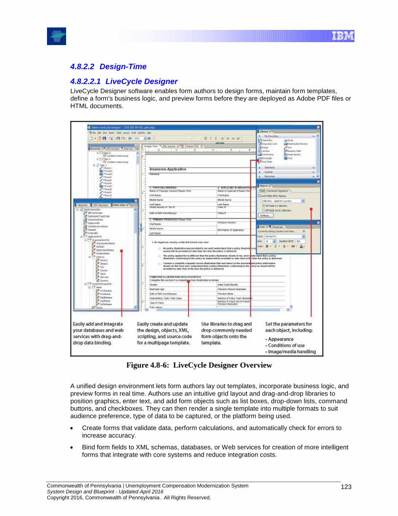
Commonwealth of Pennsylvania | Unemployment Compensation Modernization System System Design and Blueprint - Updated April 2016 Copyright 2016, Commonwealth of Pennsylvania. All Rights Reserved.
123
4.8.2.2 Design-Time
4.8.2.2.1 LiveCycle Designer LiveCycle Designer software enables form authors to design forms, maintain form templates, define a form's business logic, and preview forms before they are deployed as Adobe PDF files or HTML documents.
Figure 4.8-6: LiveCycle Designer Overview
A unified design environment lets form authors lay out templates, incorporate business logic, and preview forms in real time. Authors use an intuitive grid layout and drag-and-drop libraries to position graphics, enter text, and add form objects such as list boxes, drop-down lists, command buttons, and checkboxes. They can then render a single template into multiple formats to suit audience preference, type of data to be captured, or the platform being used.
Create forms that validate data, perform calculations, and automatically check for errors to increase accuracy.
Bind form fields to XML schemas, databases, or Web services for creation of more intelligent forms that integrate with core systems and reduce integration costs.
Commonwealth of Pennsylvania | Unemployment Compensation Modernization System System Design and Blueprint - Updated April 2016 Copyright 2016, Commonwealth of Pennsylvania. All Rights Reserved.
124
Build forms that can be published to multiple formats that users can view with Adobe Reader or a Web browser.
4.8.2.3 Administrative and Monitoring
4.8.2.3.1 Adobe Administrator Administrator is the web-based portal for accessing a variety of configuration pages to set run-time properties that control the way LiveCycle products operate. Administrators can access User Management, Adobe JMX Monitor, Watched Folder configuration (installed with Watched Folder), Process Manager and server settings (installed with LiveCycle Workflow), and administrative configuration options for other LiveCycle products.
Adobe User Management allows administrators to maintain a database for all users and groups, synchronized with one or more third-party user directories. User Management provides authorization and user management for LiveCycle products.
4.8.3 Key Concepts, Features and Capabilities
4.8.3.1 Form Types
Form types used by the Adobe forms solution include the following.
Interactive Forms
An interactive form contains one or more fields for collecting information interactively from a user. An interactive form design produces a form that can be filled online or (in the case of PDF forms) offline. Users can open the form in Acrobat, Adobe Reader, or an HTML browser and enter information into the form’s fields. An interactive form can include buttons or commands for common tasks, such as saving data to a file or printing. It can also include drop-down lists, calculations, and validations.
Note: An interactive form can be dynamic or static.
Non-interactive Forms
A non-interactive form does not respond to user interaction. This form type is often a PDF form that is downloaded by a user, printed, and filled manually. A non-interactive dynamic form can be prepopulated with data, and then made available to the users. For example, billing statements are an example of a non-interactive form.
Note: A non-interactive form can be dynamic or static.
Dynamic Forms
A dynamic form has a dynamic layout that changes based on data pre-population or through user interaction. A dynamic form may be interactive or non-interactive. A non-interactive dynamic form is prepopulated with data, then made available to a user without interactive features. An interactive dynamic form may or may not be prepopulated with data, but contains interactive fields or other interactive features that enables a user to interact with it.
A dynamic form design specifies a set of layout, presentation, and data capture rules, including the ability to calculate values based on user input. The rules are applied when a user enters data into the form or when a server merges data into a form. Dynamic forms are usually rendered by LiveCycle Forms or Acrobat 7.0 and Adobe Reader 7.0. Dynamic forms are particularly useful when displaying an undetermined amount of data to users. A fixed layout or number of pages for the form does not need to be predetermined, as is required by a static form. When rendered as a PDF form, intelligent page breaks are generated.

Commonwealth of Pennsylvania | Unemployment Compensation Modernization System System Design and Blueprint - Updated April 2016 Copyright 2016, Commonwealth of Pennsylvania. All Rights Reserved.
125
Two types of dynamic forms exist: server-side and client-side dynamic forms. Both server-side and client-side dynamic forms are based on form designs that are created in LiveCycle Designer.
Server-Side Dynamic Forms
A server-side dynamic form can be a data-driven dynamic form; that is, the form is populated with data during rendering. The amount of data determines the form’s layout. Multiple data value instances can be provided for a given field, causing the field to dynamically replicate so that each data value is displayed within the form.
Fields that are dynamically added to a dynamic form are contained in structures called subforms, which are located within the form design. An example of a server-side dynamic form is one that is part of a client application that queries a database and retrieves an unknown number of records. After retrieving records from a database, the application calls the LiveCycle Forms API to merge the data into the form. After the data is merged into the form, the application renders the form to a user.
Client-Side Dynamic Forms
A client-side dynamic form is typically used to collect data from end users by enabling them to click a button (or another control) that produces a new field in which data is entered. The new field appears on the form immediately and does not require a round trip to the server. That is, the form is not sent to the J2EE application server hosting LiveCycle Forms and then rendered back to the client web browser with the new field. An example of a client-side dynamic form is one that contains fields that enable a user to enter items to purchase and a button that enables the user to add new fields. Each time the user clicks the button, a new subform is added to the form (a subform can contain a set of related fields).
Static Forms
A static form has a fixed layout that does not change regardless of how much data is placed into the fields. A static form can be interactive, in which case a user fills the form, or non-interactive, in which case a server may prepopulate the form with data. Any fields left unfilled are present in the form but empty. Conversely, if there is more data than the form can hold, the form cannot expand to accommodate the excess data.
In the case of an interactive form, the end user cannot enter extra information beyond what the form fields can hold. Similarly, excess data merged by LiveCycle Forms overruns the area bounded by the object and the excess data is not displayed. As a result, when creating a static form, form authors position and size the objects in such a way that the objects can accommodate the largest expected set of data.
Static PDF forms are created by LiveCycle Designer when a form design is saved as a PDF file, or they can be rendered on the server by passing an XDP file to LiveCycle Forms. A static form can be generated from a dynamic form design, but once rendered as PDF, the background is locked. Static forms are easily cacheable on the server, so are quickly accessed when requested by a user.

Commonwealth of Pennsylvania | Unemployment Compensation Modernization System System Design and Blueprint - Updated April 2016 Copyright 2016, Commonwealth of Pennsylvania. All Rights Reserved.
126
4.9 Reporting
4.9.1 Introduction
WebSphere
BPM
BO Ent
DB
Universes
Enterprise Service Bus
Documents
WAS
Web Service
Descriptions
Oracle
Integration
Server
JDBC
Adapter
Content
Engine
Content
Collector
LiveCycle
Forms
Service
Registry
JDBC
Portal
IIS Web
Server
Web Server
Form Services
Portal Services
Application Services
Actions
Corticon
Server
Rule Set
Domain
Object
JMS
Business
Process
OLTP
Database
Service Component
Service
Java Client
Systems Management
Tivoli Enterprise
Monitoring
(TEMS)
WebSphere
Data Stage
Local Data Services
WebSphere
Application
Server
FileNet
DB
Reporting Services
Tivoli Ent
Portal (TEP)Tivoli Data
Warehouse
ITCAM for AD
Document Services
Form
Templates
Broker
Group Sync
Portal
Search
Portal
Repo
Audit DB
Mobile
Sync
Oracle
JSPs
LiveCycle
Designer
Capture
Desktop
Image
Files
Application
Engine
BO
Portlet
Reports
UCMS
PortletSiteMinder
Policy
Server
Workflow
Server
Identity
Minder
Server
Security Services
Business
Flow
Human
Task
Service
Service Component
WAS
Workflow Services
CBE
State
Machine
Tivoli
Omnibus
Tivoli
Netview
Console
Mobile
Server
Business-
Objects
Enterprise
Mobile
DB
B
`
Browser
Client
`
Low-Volume
Scan Station
Service
Now
B
WAS DBCBE
Persist
Fmwk
C
C
Auth
Sync
Service
Caching
Config
FmwkCaching
Fmwk
Exception
Handling
Logging
FmwkCaching
Fmwk
Portal
Fmwk
MVC
Fmwk
Messaging
Fmwk
Web App
Fmwk
Data
Access
Rule Set
Active
Directory
Portal
Identity
Service
Reporting
Database
Oracle
SiteMinder
Agent
SiteMinder
API
Security
Fmwk
`
Report
Developer
`
Reporting
Admin
Crystal
Reports
Developer
Central
Mgmt
Console
Central
Config
Manager
BO Universe
Designer
Figure 4.9-1: Reporting Services Context
The PA UCMS Reporting component is built around the understanding of the value of reporting, its accuracy, its presentation, delivery and timeliness. It provides to DLI:
Improved business workflow by allowing current staff to refocus efforts from report generation/validation efforts to performance increases and customer satisfaction
More consistent analysis and reporting through an integrated reporting solution using consistent tools from a single, integrated reporting database
Reduced dependency on paper and manual processes by re-evaluating current distribution and archival methods concerning reports
The SAP Business Objects platform of products are utilized as the foundation of the UCMS reporting solution.
The following sections describe the components and key features of the UCMS Reporting architecture.

Commonwealth of Pennsylvania | Unemployment Compensation Modernization System System Design and Blueprint - Updated April 2016 Copyright 2016, Commonwealth of Pennsylvania. All Rights Reserved.
127
4.9.2 Component Overview
Figure 4.9-2: Reporting Services Components
By using the tools from SAP BusinessObjects, an integrated business intelligence environment is formed:
Reporting enables accessing, formatting and delivering operational and management data. Crystal Reports, a DLI OIT standard for pre-defined reports, provides this capability.
Ad hoc query allows end users to interact with business information and answer ad hoc questions with minimal knowledge of the underlying data sources and structures. Web Intelligence, a thin-client tool with functionality similar to the traditional BusinessObjects client, provides these capabilities.
Statistical analysis helps analysts and managers track and analyze key business metrics. Web Intelligence, a thin-client tool with functionality similar to the traditional BusinessObjects client, provides these capabilities.
A delivery framework provides secure, integrated access to viewing and development facilities. Users enter into the report/analysis environment through a unified interface and security is integrated with the proposed security architecture of the UCMS system. This is built on top of BusinessObjects products for enterprise enablement and integration.

Commonwealth of Pennsylvania | Unemployment Compensation Modernization System System Design and Blueprint - Updated April 2016 Copyright 2016, Commonwealth of Pennsylvania. All Rights Reserved.
128
UCMS Reporting Database
Best practices for reporting, statistical analysis and ad-hoc query dictate that these types of activities should execute against a dedicated reporting database. This improves the performance of the online database by relieving it of the reporting workload, and it insulates the online database from the potential for “run-away” queries. It also allows for the use of data structures in the reporting database that are optimized for complex queries and analysis. For the UCMS project, a separate reporting database is utilized. Please refer to Chapter 8, Data Architecture for more information regarding the reporting database.
4.9.2.1 Run-Time
This section describes the run-time components of the UCMS Reporting architecture.
4.9.2.1.1 BusinessObjects Enterprise BusinessObjects is the Business Intelligence (BI) platform from Business Objects and combines the underlying platform services from Crystal Enterprise, and the Business Objects semantic layer. It provides the complete BI platform for specialized end-user tools including Crystal Reports and Web Intelligence. In addition, BusinessObjects Enterprise provides the BI platform for performance management applications.
BusinessObjects is a multi-tier system:
The Client Tier
The Application Tier
The Intelligence Tier
The Processing Tier
The Data Tier
The following diagram illustrates how each of the components fits within the multi-tier system.
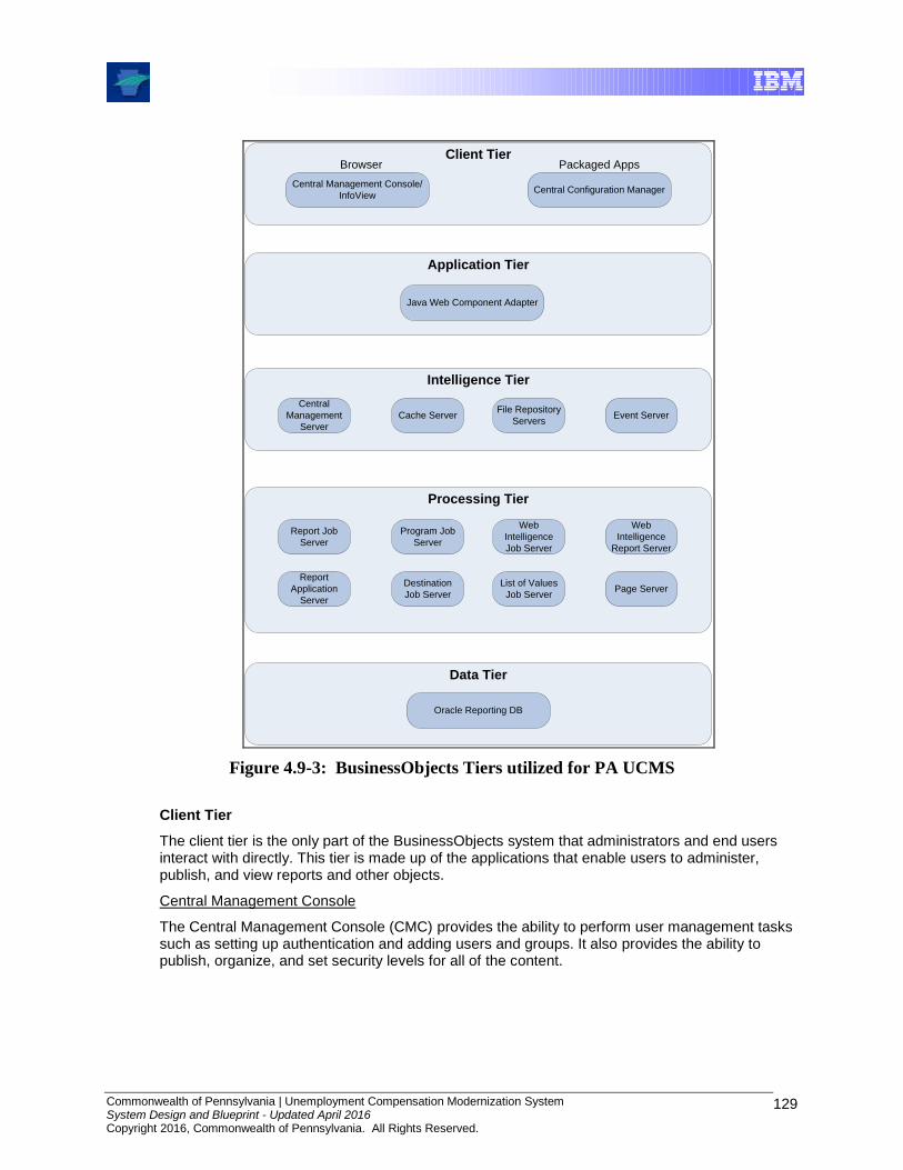
Commonwealth of Pennsylvania | Unemployment Compensation Modernization System System Design and Blueprint - Updated April 2016 Copyright 2016, Commonwealth of Pennsylvania. All Rights Reserved.
129
Client Tier
Application Tier
Intelligence Tier
Processing Tier
Data Tier
Central Management Console/
InfoViewCentral Configuration Manager
Browser Packaged Apps
Java Web Component Adapter
Central
Management
Server
Cache ServerFile Repository
ServersEvent Server
Report Job
Server
Program Job
Server
Web
Intelligence
Job Server
Web
Intelligence
Report Server
Report
Application
Server
Destination
Job Server
List of Values
Job ServerPage Server
Oracle Reporting DB
Figure 4.9-3: BusinessObjects Tiers utilized for PA UCMS
Client Tier
The client tier is the only part of the BusinessObjects system that administrators and end users interact with directly. This tier is made up of the applications that enable users to administer, publish, and view reports and other objects.
Central Management Console
The Central Management Console (CMC) provides the ability to perform user management tasks such as setting up authentication and adding users and groups. It also provides the ability to publish, organize, and set security levels for all of the content.

Commonwealth of Pennsylvania | Unemployment Compensation Modernization System System Design and Blueprint - Updated April 2016 Copyright 2016, Commonwealth of Pennsylvania. All Rights Reserved.
130
InfoView
BusinessObjects comes with InfoView, a web-based interface that users access to view, export, print, schedule and track published reports. InfoView is the main user interface for working with reports.
The web client (InfoView) makes a request to the web server, which forwards the user request directly to an application server (on the application tier) where the request is processed by components built on the Software Development Kit (SDK) – either Java or .NET.
Central Configuration Manager
The CCM is a server-management tool that provides the ability to configure each of the server components. This tool can start, stop, enable, and disable servers. Advanced server settings can be configured.
Application Tier
The application tier hosts the server-side components that are needed to process requests from the client tier as well as the components that are needed to communicate these requests to the appropriate server in the intelligence tier.
Web Component Adapter
BusinessObjects provides a Java-based web application, the WCA, which allows a web application server to run Enterprise XI applications and to host the CMC. The web server communicates directly with the web application server that hosts the SDK. The WCA runs on the web application server and provides all services that are not directly supported by the SDK. The web server passes requests directly to the web application server, which then forwards the requests on to the WCA. The WCA supports the CMC and OLAP Intelligence document viewing and interaction. For the PA UCMS, the WCA is deployed to a server running WebSphere Application Server.
Intelligence Tier
The Intelligence tier manages the Enterprise XI system. It maintains all of the security information, sends requests to the appropriate servers, manages audit information, and stores report instances. In BusinessObjects, the term “server” refers to a component of BusinessObjects rather than a physical server.
The Intelligence tier of Enterprise XI consists of five servers:
Central Management Server (CMS) – Maintains a database of information to manage the Enterprise XI Framework. Data stored includes information about users and groups, security levels, content and servers.
Cache Server – Handles all report viewing requests
Input File Repository Server (FRS) – Input FRS manages all of the report objects and program objects that have been published to the system by administrators or users.
Output File Repository Server (FRS) – The Output FRS stores and manages all of the report and program instances generated by the Report Job Server or Web Intelligence Report Server.
Event Server – Manages file-based events.
Commonwealth of Pennsylvania | Unemployment Compensation Modernization System System Design and Blueprint - Updated April 2016 Copyright 2016, Commonwealth of Pennsylvania. All Rights Reserved.
131
Processing Tier
The Processing tier accesses the data and generates the reports. The Processing tier consists of eight servers:
Report Job Server – Processes schedule reports and generates report instances (versions of report objects that contain saved data)
Program Job Server – Processes scheduled program objects such as Java programs as requested by the CMS.
Web Intelligence Job Server – Processes scheduling requests received from the CMS for Web Intelligence documents. This server is explained in more detail in the Web Intelligence section to follow.
Web Intelligence Report Server – Provides core Web Intelligence display and interaction for end-user query and analysis. This server is explained in more detail in the Web Intelligence section to follow.
Report Application Server (RAS) – Process reports that users view with the Advanced DHTML Viewer.
Destination Job Server – Processes requests that it receives from the CMS and sends the requested objects or instances to the specified destination. The Destination Job Server can send objects and instances to destinations inside the Enterprise XI system, a user’s inbox or by sending a file to an external email address.
List Of Values Job Server (LOV) – Supports the scheduling of predefined LOV or prompts. This is useful in cases where the cascading prompt levels do not change regularly such as for country, state and city.
Page Server – Responds to page requests from the Cache Server by processing reports and generating Encapsulating Page Format (EPF) files.
Data Tier
The data tier is made up of the databases that contain the data used in the reports.
4.9.2.2 Design-Time
This section describes the design-time components of the UCMS Reporting architecture.
4.9.2.2.1 Crystal Reports Developer Crystal Reports Developer is used to create static reports for the UCMS. With Crystal Reports, report designers can create many different report types, including: replicas of existing reports and forms, graphical summary reports, cross tabs and Top N or Bottom N reports. Crystal Reports provide UCMS and DLI report designers with a rich formula language and set of layout controls to allow extensive control over data manipulation and report design.
Designers can define navigation paths through reports, allowing report users to drill down or explore a set of related UC reports. Users can also sort and filter information, refresh reports, print reports and embed live report data in Microsoft Office documents.

Commonwealth of Pennsylvania | Unemployment Compensation Modernization System System Design and Blueprint - Updated April 2016 Copyright 2016, Commonwealth of Pennsylvania. All Rights Reserved.
132
4.9.2.2.2 Universe Designer Business Objects Designer is a software tool that facilitates the creation of Universes for Web Intelligence Users. A universe is a file that contains the following:
Connection parameters for one or more databases
SQL structures called objects that map actual SQL structures in the database such as columns, tables, and database functions. Objects are grouped into classes and are both visible to Web Intelligence users.
A schema of the tables and joins used in the database. Objects are built from the database structures that are included in the schema. The schema is only available to Designer users, i.e., it is not visible to Web Intelligence users.
Web Intelligence users connect to a universe, and run queries against a database. They can do data analysis and create reports using the objects in a universe, without seeing, or having to know anything about, the underlying data structures in the database.
4.9.2.3 Administrative and Monitoring
The regular administrative tasks associated with BusinessObjects Enterprise can be roughly divided into three major categories: user management, content management, and server management. Typically, the following applications are used to manage BusinessObjects Enterprise:
Central Management Console (CMC) – This web application is the administrative tool provided for managing a BusinessObjects Enterprise system. It offers a single interface through which almost every task related to user management, content management, and server management can be performed.
Central Configuration Manager (CCM) – This server administration tool is used to manage local and remote servers in the BusinessObjects installation.
Publishing Wizard – This application allows for the publishing of reporting content to BusinessObjects Enterprise quickly. Numerous options on each report can be specified. Although this application runs only on Windows, it can be used to publish reports to BusinessObjects Enterprise servers that are running on Windows or on UNIX.
While monitoring of events occurs using the CMC, critical alerts can be forwarded to Tivoli Omnibus for review and possible follow-up, e.g., creation of DLI ServiceNow Ticket. Please refer to Section 8.0, Systems Management Architecture, for more information.
4.9.3 Key Concepts, Features and Capabilities
The two main activities that users would perform with regard to reports are report viewing or report generation. Report viewing is where the user would log into the system to view/print/extract report information for previously-run reports or ad hoc queries.
4.9.3.1 Report Scheduling
While many reports are generated in batch mode, users can schedule reports on an as-needed basis. Users would do this using the same interface as they would for report viewing. The following figure depicts the high-level steps of report generation.
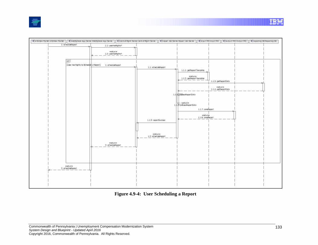
Commonwealth of Pennsylvania | Unemployment Compensation Modernization System System Design and Blueprint - Updated April 2016 Copyright 2016, Commonwealth of Pennsylvania. All Rights Reserved.
133
Figure 4.9-4: User Scheduling a Report
Commonwealth of Pennsylvania | Unemployment Compensation Modernization System System Design and Blueprint - Updated April 2016 Copyright 2016, Commonwealth of Pennsylvania. All Rights Reserved.
134
Steps in Scheduling a Report:
1. The InfoView portlet sends the schedule request in a URL through the web server to the web application server.
2. WebSphere interprets the request and the values sent, and determines if the request is a schedule request. The web application server sends the schedule time, database logon values, parameter values, destination, and format to the specified Central Management Server (CMS).
3. The CMS ensures that the user has rights to schedule the object. If the user has sufficient rights, the CMS adds a new record to the System database. The CMS also adds the instance to its list of pending schedules.
4. The CMS checks its pending schedule list every 15 seconds. When the CMS finds a report that is ready to be scheduled, the CMS evaluates whether there is an available Report Job Server. The CMS sends the schedule request along with the report location, database logon, parameter, format, and destination information to the Report Job Server.
5. The Report Job Server requests the report from the Input File Repository Server (FRS).
6. The Input FRS streams the report to the Report Job Server.
7. The Report Job Server opens the report and connects to the database to query for the report data.
8. The database returns the report data to the Report Job Server. The Report Job Server then processes the report.
9. Once the report is processed, the Report Job Server saves the report to the Output FRS.
10. The Report Job Server reports back to the CMS to let the CMS know that the report has been processed successfully.
11. The CMS updates the instance record in the system database to change the instance status to Success.
4.9.3.2 Web Intelligence Query Scheduling
Users are able to schedule ad hoc queries on an as-needed basis. The following figure depicts the high-level steps of Web Intelligence query generation

Commonwealth of Pennsylvania | Unemployment Compensation Modernization System System Design and Blueprint - Updated April 2016 Copyright 2016, Commonwealth of Pennsylvania. All Rights Reserved.
135
Figure 4.9-5: User Scheduling a Web Intelligence Query/Report
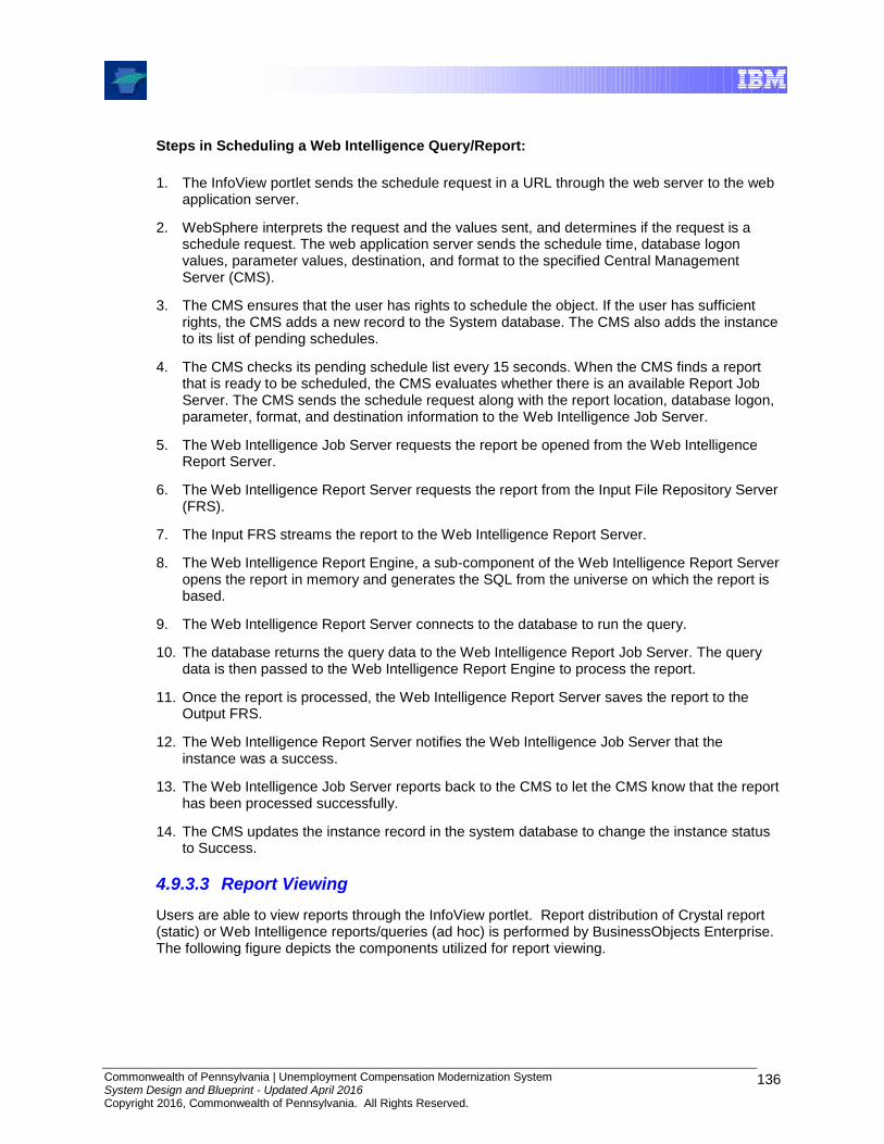
Commonwealth of Pennsylvania | Unemployment Compensation Modernization System System Design and Blueprint - Updated April 2016 Copyright 2016, Commonwealth of Pennsylvania. All Rights Reserved.
136
Steps in Scheduling a Web Intelligence Query/Report:
1. The InfoView portlet sends the schedule request in a URL through the web server to the web application server.
2. WebSphere interprets the request and the values sent, and determines if the request is a schedule request. The web application server sends the schedule time, database logon values, parameter values, destination, and format to the specified Central Management Server (CMS).
3. The CMS ensures that the user has rights to schedule the object. If the user has sufficient rights, the CMS adds a new record to the System database. The CMS also adds the instance to its list of pending schedules.
4. The CMS checks its pending schedule list every 15 seconds. When the CMS finds a report that is ready to be scheduled, the CMS evaluates whether there is an available Report Job Server. The CMS sends the schedule request along with the report location, database logon, parameter, format, and destination information to the Web Intelligence Job Server.
5. The Web Intelligence Job Server requests the report be opened from the Web Intelligence Report Server.
6. The Web Intelligence Report Server requests the report from the Input File Repository Server (FRS).
7. The Input FRS streams the report to the Web Intelligence Report Server.
8. The Web Intelligence Report Engine, a sub-component of the Web Intelligence Report Server opens the report in memory and generates the SQL from the universe on which the report is based.
9. The Web Intelligence Report Server connects to the database to run the query.
10. The database returns the query data to the Web Intelligence Report Job Server. The query data is then passed to the Web Intelligence Report Engine to process the report.
11. Once the report is processed, the Web Intelligence Report Server saves the report to the Output FRS.
12. The Web Intelligence Report Server notifies the Web Intelligence Job Server that the instance was a success.
13. The Web Intelligence Job Server reports back to the CMS to let the CMS know that the report has been processed successfully.
14. The CMS updates the instance record in the system database to change the instance status to Success.
4.9.3.3 Report Viewing
Users are able to view reports through the InfoView portlet. Report distribution of Crystal report (static) or Web Intelligence reports/queries (ad hoc) is performed by BusinessObjects Enterprise. The following figure depicts the components utilized for report viewing.
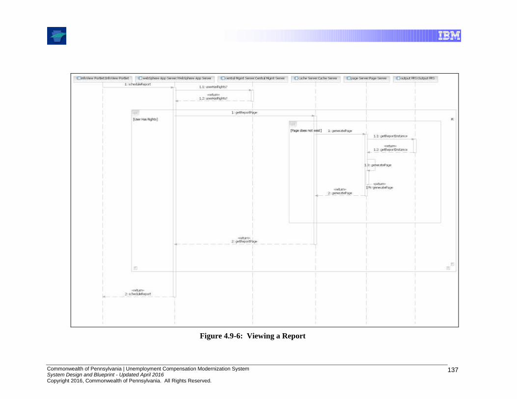
Commonwealth of Pennsylvania | Unemployment Compensation Modernization System System Design and Blueprint - Updated April 2016 Copyright 2016, Commonwealth of Pennsylvania. All Rights Reserved.
137
Figure 4.9-6: Viewing a Report
Commonwealth of Pennsylvania | Unemployment Compensation Modernization System System Design and Blueprint - Updated April 2016 Copyright 2016, Commonwealth of Pennsylvania. All Rights Reserved.
138
Steps in Viewing a Report:
1. The InfoView portlet sends a view report request in a URL through the web server to the web application server.
2. WebSphere Application Server interprets the requested page and the values sent in the URL request and determines if it is a request to view the first page of the selected report instance. The web application server sends a request to the CMS to ensure that the user has rights to view the instance.
3. The CMS checks the system database to verify the user rights.
4. The CMS sends a response to WebSphere to confirm the user has sufficient rights to view the instance.
5. WebSphere sends a request to the Cache Server requesting the first page of the report instance.
6. The Cache Server checks to see if the page already exists. If the page does exist, the Cache Server can return the page to WebSphere. If the page does not exist, the Cache Server sends a request for the Page Server to generate the page.
7. The Page Server requests the report instance from the Output FRS.
8. The Output FRS streams a copy of the instance to the Page Server. The Page Server opens the report in its memory, finds the data and generates pages.
9. The Page Server sends the report instance page to the Cache Server. The Cache Server stores a copy of the report instance page in its cache directory.
10. The Page Server sends the report instance page to WebSphere.
11. WebSphere sends the report instance page back to InfoView to be rendered in the portal.
4.9.3.4 Security
The security integration between the Portal and BusinessObjects Enterprise relies on authentication and authorization control mechanisms as well as network and operating system controls. The authentication and authorization are performed by Siteminder when the user initially enters the Portals. Access to BusinessObjects are controlled at the Portlet level based upon the user’s SiteMinder role.
Users invoke BusinessObjects from the Portal and the user’s role determines what the user is authorized to do. The user ids and roles are mapped between BusinessObjects and Siteminder based upon detailed specifications to be determined during micro-design of the solution.
The network and host infrastructure supporting the applications are controlled through access control lists and operating system controls to limit access only to authorized objects.
4.9.3.5 Scalability
The BusinessObjects Enterprise architecture is scalable in that it allows for a multitude of server configurations, ranging from stand-alone, single-machine environments, to large-scale deployments supporting global organizations. The flexibility offered by the product’s architecture allows a system to be set up that suits the current reporting requirements, without limiting the possibilities for future growth and expansion.
Referring back to Figure 4.9-3 the components that make up each of these tiers can be installed on one machine, or spread across many. Each tier is a layer of the system that is responsible for a role in the overall architecture. There are many servers involved in this architecture. Some of these servers are only responsible for doing work, others only responsible for managing the servers doing the work.
The services can be vertically scaled to take full advantage of the hardware that they are running on, and they can be horizontally scaled to take advantage of multiple computers over a network

Commonwealth of Pennsylvania | Unemployment Compensation Modernization System System Design and Blueprint - Updated April 2016 Copyright 2016, Commonwealth of Pennsylvania. All Rights Reserved.
139
environment. This means that the services can all run on the same machine, or they can run on separate machines. The same service can also run in multiple instances on a single machine.
For example, the CMS and the Event Server can run on one machine, while the Page Server runs on a separate machine (horizontal scaling). If the Page Server is running on a multi-processor computer, then multiple Page Servers can be run on it (vertical scaling). The important thing to understand is that even though these are called servers, they are actually services and daemons that do not need to run on separate computers. For the UCMS project, all of the servers except for the Web Intelligence Job and Report servers are installed on one server. The Web Intelligence Job and Report servers are installed on a separate server.
4.10 Wage Functionality Component Model
4.10.1 Introduction
The Component Model describes and documents the entire hierarchy of components in terms of their responsibilities, their interfaces, their (static) relationships, and the way they collaborate to deliver required functionality. It is used to describe complex solutions and to ensure that different teams can work efficiently with a reuse and global design approach.
A Component Model is used to bridge the gap between requirements and the solution by ensuring that detailed specifications need not be made immediately available but can instead be elaborated over a period of time. It also mandates the main design principles and overall structure. This is achieved by defining smaller problem scopes that can be handed to different teams for resolution while encouraging reuse across teams.
Each Component in the Component Model is an independent part of the system. It is identified by its responsibilities and eventually by the interface(s) it offers that are collectively used to achieve the system behavior. Components can be decomposed into smaller components or composed into larger components. A Component is a very general concept and is not restricted to any particular technology. It is an encapsulated part of a software system with well-defined interfaces through which access to its services are provided.
This release has a number of application and technical components used to deliver the functionality. The diagrams in the model focus primarily on the application components and which technical components are used to assist in achieving the desired system behavior.
The “Portal User Interfaces” component provides the user interfaces to work with the wage records and to work with human tasks that are being managed with workflow. The “Employer Quarterly Reports Services” component provides the functionality to generate the UC-2 and UC-2A Quarterly Reports that are printed and mailed to employers. The “Wage and Tax Intake Services” component provides the functionality to process and edit Wage and Tax records received on the UC-2 and UC-2A. This component uses two other components, the “Tax Remittance Processing Services” component and the “Wage Record Services” component.

Commonwealth of Pennsylvania | Unemployment Compensation Modernization System System Design and Blueprint - Updated April 2016 Copyright 2016, Commonwealth of Pennsylvania. All Rights Reserved.
140
4.10.2 Component Overview
The following diagram is a Component Overview diagram for the Wage and Tax Functionality
Figure 4.10-1: Component Overview – Wage and Tax

Commonwealth of Pennsylvania | Unemployment Compensation Modernization System System Design and Blueprint - Updated April 2016 Copyright 2016, Commonwealth of Pennsylvania. All Rights Reserved.
141
4.10.3 Component Relationships
The Component Relationship Diagram is used to depict the static component relationships and dependencies among components. It is represented by a variation of the UML Class Diagram. The diagram below is the main overview Component Relationship Diagram. It contains the primary components for Wage Functionality.
Figure 4.10-2: Component Relationship Diagram

Commonwealth of Pennsylvania | Unemployment Compensation Modernization System System Design and Blueprint - Updated April 2016 Copyright 2016, Commonwealth of Pennsylvania. All Rights Reserved.
142
4.10.3.1 UI Component Diagram
The diagram below shows the components used specifically for the creation of the user interface functionality for this release. It contains components and interfaces provided by the PortalUserInterfaces component.
Figure 4.10-3: UI Component Diagram

Commonwealth of Pennsylvania | Unemployment Compensation Modernization System System Design and Blueprint - Updated April 2016 Copyright 2016, Commonwealth of Pennsylvania. All Rights Reserved.
143
4.10.3.2 Intake Component Diagram
The diagram below shows the components used to manage the intake processing of UC-2 and UC-2A employer reports. It contains components and interfaces provided by the components.
Figure 4.10-4: Intake Component Diagram
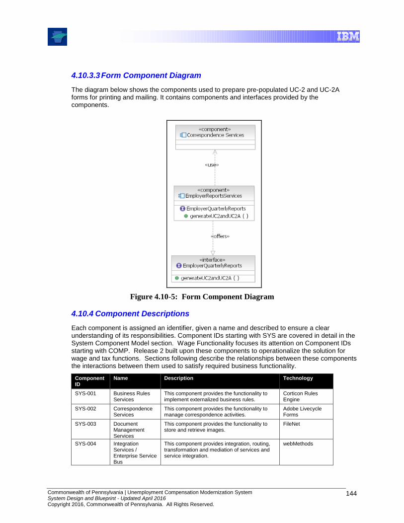
Commonwealth of Pennsylvania | Unemployment Compensation Modernization System System Design and Blueprint - Updated April 2016 Copyright 2016, Commonwealth of Pennsylvania. All Rights Reserved.
144
4.10.3.3 Form Component Diagram
The diagram below shows the components used to prepare pre-populated UC-2 and UC-2A forms for printing and mailing. It contains components and interfaces provided by the components.
Figure 4.10-5: Form Component Diagram
4.10.4 Component Descriptions
Each component is assigned an identifier, given a name and described to ensure a clear understanding of its responsibilities. Component IDs starting with SYS are covered in detail in the System Component Model section. Wage Functionality focuses its attention on Component IDs starting with COMP. Release 2 built upon these components to operationalize the solution for wage and tax functions. Sections following describe the relationships between these components the interactions between them used to satisfy required business functionality.
Component ID
Name Description Technology
SYS-001 Business Rules Services
This component provides the functionality to implement externalized business rules.
Corticon Rules Engine
SYS-002 Correspondence Services
This component provides the functionality to manage correspondence activities.
Adobe Livecycle Forms
SYS-003 Document Management Services
This component provides the functionality to store and retrieve images.
FileNet
SYS-004 Integration Services / Enterprise Service Bus
This component provides integration, routing, transformation and mediation of services and service integration.
webMethods

Commonwealth of Pennsylvania | Unemployment Compensation Modernization System System Design and Blueprint - Updated April 2016 Copyright 2016, Commonwealth of Pennsylvania. All Rights Reserved.
145
Component ID
Name Description Technology
SYS-005 Portal Services This component provides a framework to manage portlets and a portal community for UCMS activities.
Portal
SYS-006 Reporting Services
This component provides a framework to create, manage and view reports.
Business Objects Enterprise
SYS-007 Workflow Services This component provides human task management, business process execution and business state machines
WebSphere Process Server
COMP-001 Portal User Interfaces
This component provides the user interfaces used to work with the wage records and to work with the human tasks that are being manage by workflow.
Portal
COMP-002 Wage And Tax Intake Services
This component provides intake processing and editing of Wage and Tax records received on UC-2 and UC-2A reports
Business Process Execution Language (BPEL)
COMP-003 Wage Record Services
This component provides services to retrieve, search for, update and post wage records.
J2EE-based Services
COMP-004 Tax And Remittance Processing Services
This component provides services to retrieve and post tax and remittances
J2EE-based Services
COMP-005 Employer Reports Services
This component provides services to generate reports mailed to employers
Correspondence Engine
4.10.5 Component Interaction
Component Interaction Diagrams are used to illustrate how components collaborate to achieve system functionality. It is represented by a variation of the UML Collaboration or Sequence Diagram.
4.10.5.1 Intake Component Interaction Diagram
The following diagrams show the interaction of components used to provide the intake processing and editing of UC-2 and UC-2A forms.
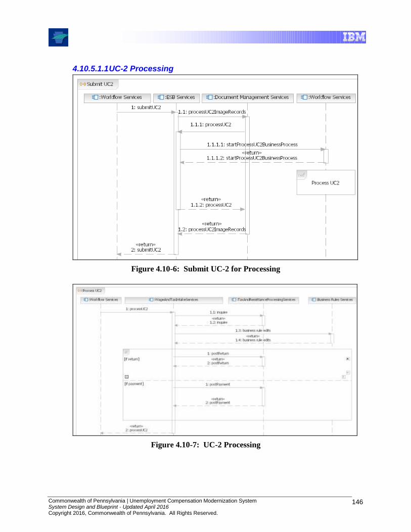
Commonwealth of Pennsylvania | Unemployment Compensation Modernization System System Design and Blueprint - Updated April 2016 Copyright 2016, Commonwealth of Pennsylvania. All Rights Reserved.
146
4.10.5.1.1 UC-2 Processing
Figure 4.10-6: Submit UC-2 for Processing
Figure 4.10-7: UC-2 Processing
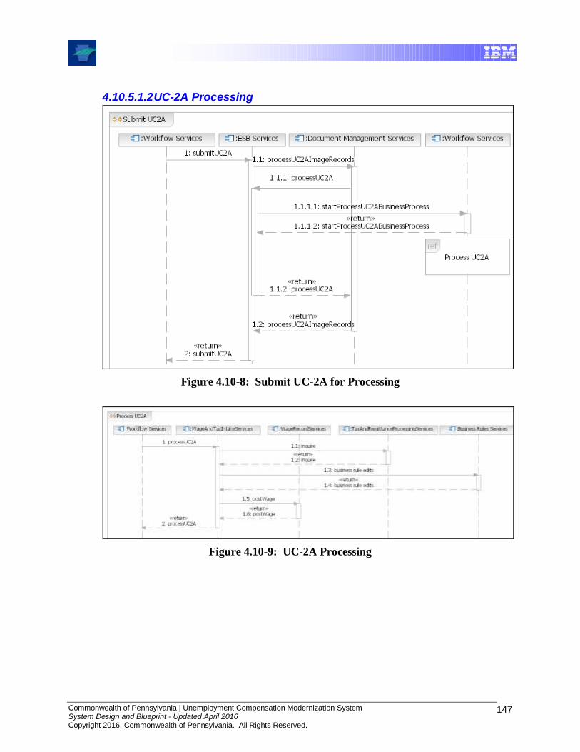
Commonwealth of Pennsylvania | Unemployment Compensation Modernization System System Design and Blueprint - Updated April 2016 Copyright 2016, Commonwealth of Pennsylvania. All Rights Reserved.
147
4.10.5.1.2 UC-2A Processing
Figure 4.10-8: Submit UC-2A for Processing
Figure 4.10-9: UC-2A Processing

Commonwealth of Pennsylvania | Unemployment Compensation Modernization System System Design and Blueprint - Updated April 2016 Copyright 2016, Commonwealth of Pennsylvania. All Rights Reserved.
148
4.10.5.2 Employer Reports Component Interaction Diagram
The following diagram shows the interaction of components used to provide the printing and mailing of Employer Quarterly Reports, UC-2 and UC-2A forms.
Figure 4.10-10: Employer Reports Component Interaction Diagram

Commonwealth of Pennsylvania | Unemployment Compensation Modernization System System Design and Blueprint - Updated April 2016 Copyright 2016, Commonwealth of Pennsylvania. All Rights Reserved.
149
4.10.5.3 Wage Record User Interface Component Interaction Diagram
The following diagrams show the interaction of components used to provide a user interface to search, view, update, and submit wages.
Figure 4.10-11: Wage Record Interface Component Interaction Diagram

Commonwealth of Pennsylvania | Unemployment Compensation Modernization System System Design and Blueprint - Updated April 2016 Copyright 2016, Commonwealth of Pennsylvania. All Rights Reserved.
150
4.10.5.4 Workflow Managed Task User Interface Component Interaction Diagram
The following diagrams show the interaction of components used to provide a user interface to get workflowed human tasks and complete or escalate the task.
Figure 4.10-12: Workflow Managed Task User Interface Component Interaction Diagram

Commonwealth of Pennsylvania | Unemployment Compensation Modernization System System Design and Blueprint - Updated April 2016 Copyright 2016, Commonwealth of Pennsylvania. All Rights Reserved.
151
4.11 Tax Component Model
4.11.1 Introduction
The Component Model for the Tax Functionality is the same as that from the Wage Functionality. This is to be expected: Tax added operational code Tax functions, building upon the Common and Wage release components and base functionality. It is at this point that this Blueprint begins to separate from the detailed database development, operational and functional models, and business processes. In particular, the business processes and associated tasks are described in Design Packages, Detailed System Design documents, Use Cases, and supporting documentation. The business processes and associated functionality are separated into modules. Besides Base, Common, Department of Labor, and shared portlet modules used across all of the functional areas, there are modules separated into groups associated with specific Unemployment Compensation topics for:
Accounting
Collections
Compliance
Field Audits
Ratings
Receivables
Registration
Tax Appeals
Wages
The documentation for the modules is gathered into Use Case and other design artifacts created during the design of the corresponding functions. Each functional group consists of an extensive collection of materials that can include Business Process models, operational artifacts, logical and physical database models etc.
Some of the detailed design artifacts and Use Case documents are substantially larger than this Blueprint. As a result, it is impractical to include them here, even as Appendices. In addition, while the UCMS solution architecture (as described in this Blueprint) has remained relatively consistent since the original version of the Blueprint was released in 2007, the modules and their design artifacts have changed as the detailed design has matured and new features have been added via design change requests.
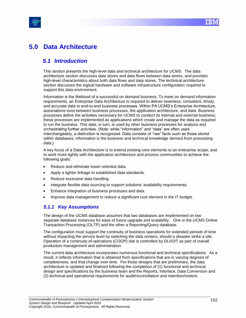
Commonwealth of Pennsylvania | Unemployment Compensation Modernization System System Design and Blueprint - Updated April 2016 Copyright 2016, Commonwealth of Pennsylvania. All Rights Reserved.
152
5.0 Data Architecture
5.1 Introduction
This section presents the high-level data and technical architecture for UCMS. The data architecture section discusses data stores and data flows between data stores, and provides high-level characteristics about both data flows and data stores. The technical architecture section discusses the logical hardware and software infrastructure configuration required to support this data environment.
Information is the lifeblood of a successful on demand business. To meet on demand information requirements, an Enterprise Data Architecture is required to deliver seamless, consistent, timely, and accurate data to end-to-end business processes. Within PA UCMS’s Enterprise Architecture, associations exist between business processes, the application architecture, and data. Business processes define the activities necessary for UCMS to conduct its internal and external business; these processes are implemented as applications which create and manage the data as required to run the business. This data, in turn, is used by other business processes for analysis and orchestrating further activities. (Note: while “information” and “data” are often used interchangeably, a distinction is recognized. Data consists of “raw” facts such as those stored within databases; information is the business and technical knowledge derived from processing data.)
A key focus of a Data Architecture is to extend existing core elements to an enterprise scope, and to work more tightly with the application architecture and process communities to achieve the following goals:
Reduce and eliminate tower-oriented data.
Apply a tighter linkage to established data standards.
Reduce excessive data handling.
Integrate flexible data sourcing to support solutions' availability requirements.
Enhance integration of business processes and data.
Improve data management to reduce a significant cost element in the IT budget.
5.1.1 Key Assumptions
The design of the UCMS database assumes that two databases are implemented on two separate database instances for ease of future upgrade and scalability. One is the UCMS Online Transaction Processing (OLTP) and the other a Reporting/Query database.
The configuration must support the continuity of business operations for extended periods of time without impacting the service level by switching the data centers, should a disaster strike a site. Operation of a continuity-of-operations (COOP) site is controlled by DLI/OIT as part of overall production management and administration.
The current data architecture incorporates numerous functional and technical specifications. As a result, it reflects information that is obtained from specifications that are in varying degrees of completeness, and that change over time. For those designs that are preliminary, the data architecture is updated and finalized following the completion of (1) functional and technical design and specifications by the business team and the Reports, Interface, Data Conversion and (2) technical and operational requirements for audit/reconciliation and retention/restore.
Commonwealth of Pennsylvania | Unemployment Compensation Modernization System System Design and Blueprint - Updated April 2016 Copyright 2016, Commonwealth of Pennsylvania. All Rights Reserved.
153
The design of the data architecture assumes that a separate Reporting/Query database is established to support retention and reporting service requirements, and additional reporting requirements beyond those already established.
The design of the Data Architecture assumes that UCMS OLTP database is the focal point for Online Transaction Processing (OLTP) of UCMS.
5.1.2 Key Requirements
The technical architecture must support the performance, disaster recovery, volume and availability requirements, subject to the COOP operational responsibility described earlier. The technical architecture must assure UCMS users that the UCMS system can handle the processing requirements and remain viable in adverse situations such as hardware failure.
Data stores, as subject-oriented collections of data, do not, per se, satisfy requirements. Rather, it is the lower-level structures included in a data store, such as tables and procedures that are traced to requirements. Nevertheless, reports, interfaces, and other requirements have been considered during the development of this document.
5.2 Data Architecture Framework
E2E (End-to-End) Data Architecture Framework
The E2E Data Architecture Framework consists of multiple tiers, as depicted in the following figure. This is a specification framework and not all parts are within the scope of the UCMS project. For UCMS it is used as a data reference architecture and for patterns that are used in the design. The Business Data Architecture, consisting of the Subject Areas, Enterprise Information Model, and the Messaging Standards, establishes the foundation of the architecture. The Data Sharing Architecture, Logical Data Stores, and the Trusted Data Stores are built upon that foundation and its overall guiding principles. The purpose is to develop a well-integrated enterprise data architecture built upon standards, controlled redundancy, and maximized data quality. In order to accomplish this task, the architecture components must be well-governed and made accessible via the Metadata layer. In addition, the diagram below shows a Data Warehouse (DW) which implies four key tenets including Subject Orientation, Time Variance, Persistence and Integration, not all of which are controlled by the UCMS application.
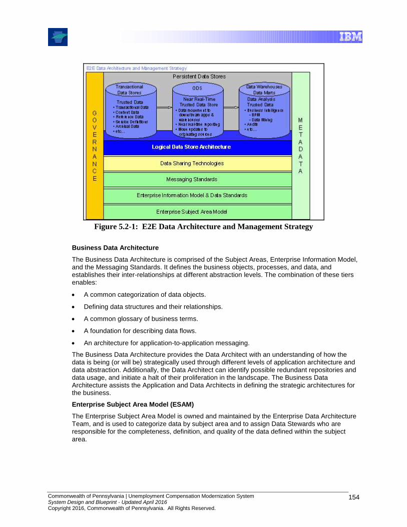
Commonwealth of Pennsylvania | Unemployment Compensation Modernization System System Design and Blueprint - Updated April 2016 Copyright 2016, Commonwealth of Pennsylvania. All Rights Reserved.
154
Figure 5.2-1: E2E Data Architecture and Management Strategy
Business Data Architecture
The Business Data Architecture is comprised of the Subject Areas, Enterprise Information Model, and the Messaging Standards. It defines the business objects, processes, and data, and establishes their inter-relationships at different abstraction levels. The combination of these tiers enables:
A common categorization of data objects.
Defining data structures and their relationships.
A common glossary of business terms.
A foundation for describing data flows.
An architecture for application-to-application messaging.
The Business Data Architecture provides the Data Architect with an understanding of how the data is being (or will be) strategically used through different levels of application architecture and data abstraction. Additionally, the Data Architect can identify possible redundant repositories and data usage, and initiate a halt of their proliferation in the landscape. The Business Data Architecture assists the Application and Data Architects in defining the strategic architectures for the business.
Enterprise Subject Area Model (ESAM)
The Enterprise Subject Area Model is owned and maintained by the Enterprise Data Architecture Team, and is used to categorize data by subject area and to assign Data Stewards who are responsible for the completeness, definition, and quality of the data defined within the subject area.

Commonwealth of Pennsylvania | Unemployment Compensation Modernization System System Design and Blueprint - Updated April 2016 Copyright 2016, Commonwealth of Pennsylvania. All Rights Reserved.
155
Enterprise Data Model (EDM)
The EDM is a high-level, conceptual data model that defines business data structures and their inter-relationships, and represents business data needs. The EDM is managed by the Enterprise Data Architecture Team, and multiple groups collaborate in developing and maintaining it. (Note: EDM was formerly known as the Enterprise Information Model or EIM)
Data Sharing Technologies
Due to complexities and inter-dependencies within the UCMS environment, information flows between applications must be identified, analyzed, and documented to ensure the accuracy and efficiency of business applications. The criteria for specifying and managing information flows are detailed in the Detailed Systems Design documents and includes:
The name and type of the information flows or interfaces.
The specific data which is shared.
How the data is exchanged.
The required timeliness of data sharing.
Adhering to these criteria aids in:
Reducing business problems caused by data errors.
Highlighting the number of applications through which the information flows.
Highlighting the number and types of data transformations, including where redundant transformations exist.
Highlighting data quality issues.
Data Migration
Within the E2E Data Architecture, it is imperative to identify the systems which are responsible for transferring data from one location to another. The controlling processes and established schedules must be documented to ensure prerequisite compliance, capacity requirements, etc. ETL (Extract, Transform, Load)
ETL processes are required to acquire data, ensure it is in a usable form by applications, and deliver it to the appropriate data stores.
Logical Data Stores Architecture
A Logical Data Store is a high-level representation (or business view) of data contained within one or more physical data stores. An understanding of the inter-relationships between data elements and between the data and applications is required to define the Logical Data Architecture. Persistent Data Architecture
Trusted Data Stores Environment
Trusted Data Stores are sources which have been formally certified as such. This process is designed to ensure quality, reliability, and security criteria are met, and in so doing, assure the consuming applications of the data's enterprise value.
Trusted data stores occur in three implementation formats and serve differing purposes:
Commonwealth of Pennsylvania | Unemployment Compensation Modernization System System Design and Blueprint - Updated April 2016 Copyright 2016, Commonwealth of Pennsylvania. All Rights Reserved.
156
1. Transactional Data Stores
Transactional Data Stores support the Online Transaction Processing environment (OLTP), and are usually the origination points of trusted data. These sources directly support the business processes according to established rules. In general, these stores are regarded as Authoritative Source Systems. 2. Operational Data Stores (ODS)
Operational Data Stores accumulate and manage transactional data supplied by operational systems. A key facet of ODS data is its meaning or value is not changed from its origination point(s), but it can be cleansed, enriched, and transformed as needed. Another key facet is it doesn't contain historical data. 3. Data Warehouses & Data Marts
Data Warehouses and Data Marts are typically used by Business Intelligence and Reporting applications for analyzing and reporting the business' status. As such, they contain historical and derived/calculated data, and the solutions which use this data drive subsequent business direction and activities. Data Marts are often sourced from Data Warehouses and are tailored for more specialized analysis and reporting. The Data Warehouse Architecture section provides an overview, and examples of trusted data stores can be seen in the Data Warehouse Target Architecture. However, UCMS does not implement a Data Warehouse. Trusted data can be “cascaded”, i.e., trusted sources can feed downstream repositories, which can, in turn, be certified as trusted.
The Reporting/Query database/data mart contains historical and derived/ calculated data that UCMS reports need. This Reporting/Query data base is sourced from the UCMS operational database. This type of data mart it not a dimensional model. The model is built to best meet the reporting needs and can be in 3rd normal form.
5.3 High-Level Physical Data Architecture
This section presents the UCMS High Level Physical Data Architecture, the Data Architecture Components, software and the data stores.
The architecture shows various data stores as follows:
OLTP
Audit Database
Reporting/Financial Database
FileNet database (content management)
ETL data store
Data Recovery data store
The UCMS database supports real-time business transactions requiring quick response times, the generation of a broad range of reports and queries, and the archival of large image files that, while essential to the business, are infrequently accessed. In order to achieve the best performance and stability the database is separated into different physical databases.
Operational Database - UCMS applications interact with the operational database, which is optimized for response time. This database acts as the master database as the data it contains reflects official UCMS case and financial management transactions that have potential legal or financial import. It is implemented as a relational database.
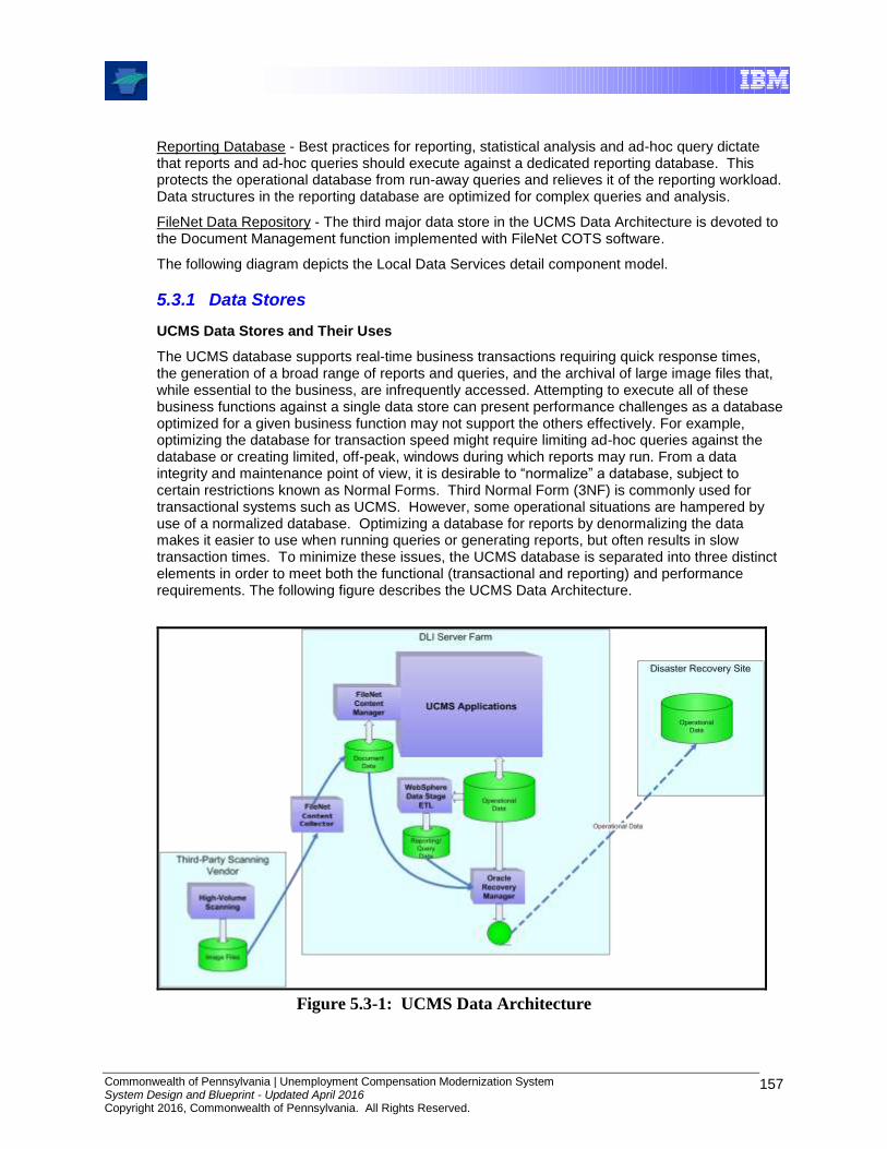
Commonwealth of Pennsylvania | Unemployment Compensation Modernization System System Design and Blueprint - Updated April 2016 Copyright 2016, Commonwealth of Pennsylvania. All Rights Reserved.
157
Reporting Database - Best practices for reporting, statistical analysis and ad-hoc query dictate that reports and ad-hoc queries should execute against a dedicated reporting database. This protects the operational database from run-away queries and relieves it of the reporting workload. Data structures in the reporting database are optimized for complex queries and analysis.
FileNet Data Repository - The third major data store in the UCMS Data Architecture is devoted to the Document Management function implemented with FileNet COTS software.
The following diagram depicts the Local Data Services detail component model.
5.3.1 Data Stores
UCMS Data Stores and Their Uses
The UCMS database supports real-time business transactions requiring quick response times, the generation of a broad range of reports and queries, and the archival of large image files that, while essential to the business, are infrequently accessed. Attempting to execute all of these business functions against a single data store can present performance challenges as a database optimized for a given business function may not support the others effectively. For example, optimizing the database for transaction speed might require limiting ad-hoc queries against the database or creating limited, off-peak, windows during which reports may run. From a data integrity and maintenance point of view, it is desirable to “normalize” a database, subject to certain restrictions known as Normal Forms. Third Normal Form (3NF) is commonly used for transactional systems such as UCMS. However, some operational situations are hampered by use of a normalized database. Optimizing a database for reports by denormalizing the data makes it easier to use when running queries or generating reports, but often results in slow transaction times. To minimize these issues, the UCMS database is separated into three distinct elements in order to meet both the functional (transactional and reporting) and performance requirements. The following figure describes the UCMS Data Architecture.
Figure 5.3-1: UCMS Data Architecture
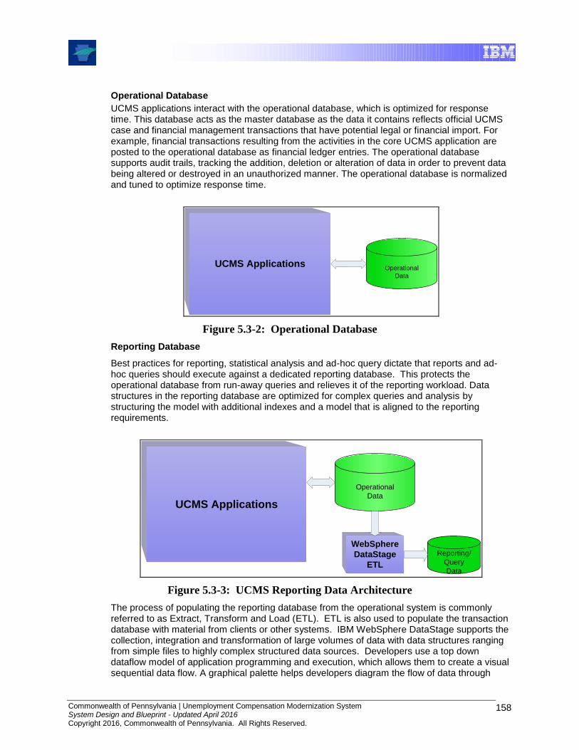
Commonwealth of Pennsylvania | Unemployment Compensation Modernization System System Design and Blueprint - Updated April 2016 Copyright 2016, Commonwealth of Pennsylvania. All Rights Reserved.
158
Operational Database
UCMS applications interact with the operational database, which is optimized for response time. This database acts as the master database as the data it contains reflects official UCMS case and financial management transactions that have potential legal or financial import. For example, financial transactions resulting from the activities in the core UCMS application are posted to the operational database as financial ledger entries. The operational database supports audit trails, tracking the addition, deletion or alteration of data in order to prevent data being altered or destroyed in an unauthorized manner. The operational database is normalized and tuned to optimize response time.
UCMS ApplicationsOperational
Data
Figure 5.3-2: Operational Database
Reporting Database
Best practices for reporting, statistical analysis and ad-hoc query dictate that reports and ad-hoc queries should execute against a dedicated reporting database. This protects the operational database from run-away queries and relieves it of the reporting workload. Data structures in the reporting database are optimized for complex queries and analysis by structuring the model with additional indexes and a model that is aligned to the reporting requirements.
UCMS Applications
Reporting/
Query
Data
WebSphere
DataStage
ETL
Operational
Data
Figure 5.3-3: UCMS Reporting Data Architecture
The process of populating the reporting database from the operational system is commonly referred to as Extract, Transform and Load (ETL). ETL is also used to populate the transaction database with material from clients or other systems. IBM WebSphere DataStage supports the collection, integration and transformation of large volumes of data with data structures ranging from simple files to highly complex structured data sources. Developers use a top down dataflow model of application programming and execution, which allows them to create a visual sequential data flow. A graphical palette helps developers diagram the flow of data through
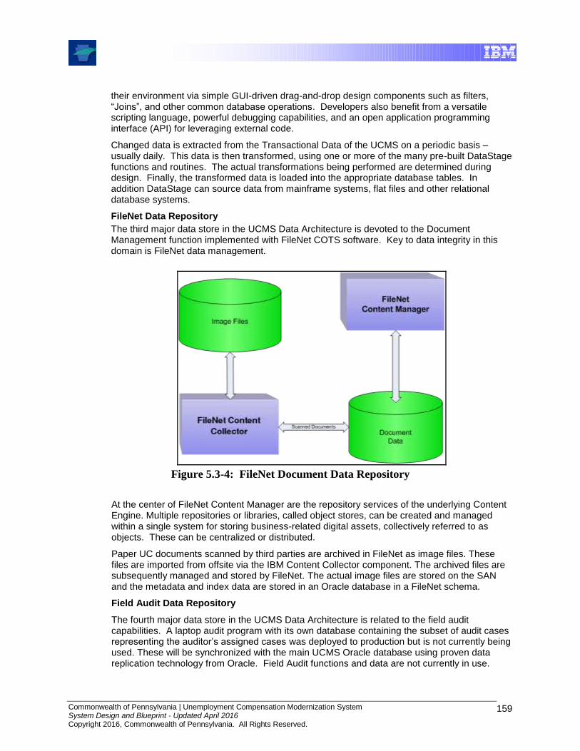
Commonwealth of Pennsylvania | Unemployment Compensation Modernization System System Design and Blueprint - Updated April 2016 Copyright 2016, Commonwealth of Pennsylvania. All Rights Reserved.
159
their environment via simple GUI-driven drag-and-drop design components such as filters, “Joins”, and other common database operations. Developers also benefit from a versatile scripting language, powerful debugging capabilities, and an open application programming interface (API) for leveraging external code.
Changed data is extracted from the Transactional Data of the UCMS on a periodic basis – usually daily. This data is then transformed, using one or more of the many pre-built DataStage functions and routines. The actual transformations being performed are determined during design. Finally, the transformed data is loaded into the appropriate database tables. In addition DataStage can source data from mainframe systems, flat files and other relational database systems.
FileNet Data Repository
The third major data store in the UCMS Data Architecture is devoted to the Document Management function implemented with FileNet COTS software. Key to data integrity in this domain is FileNet data management.
Figure 5.3-4: FileNet Document Data Repository
At the center of FileNet Content Manager are the repository services of the underlying Content Engine. Multiple repositories or libraries, called object stores, can be created and managed within a single system for storing business-related digital assets, collectively referred to as objects. These can be centralized or distributed.
Paper UC documents scanned by third parties are archived in FileNet as image files. These files are imported from offsite via the IBM Content Collector component. The archived files are subsequently managed and stored by FileNet. The actual image files are stored on the SAN and the metadata and index data are stored in an Oracle database in a FileNet schema.
Field Audit Data Repository
The fourth major data store in the UCMS Data Architecture is related to the field audit capabilities. A laptop audit program with its own database containing the subset of audit cases representing the auditor’s assigned cases was deployed to production but is not currently being used. These will be synchronized with the main UCMS Oracle database using proven data replication technology from Oracle. Field Audit functions and data are not currently in use.

Commonwealth of Pennsylvania | Unemployment Compensation Modernization System System Design and Blueprint - Updated April 2016 Copyright 2016, Commonwealth of Pennsylvania. All Rights Reserved.
160
Note that while Field Audit code has been created, it is not currently (2014) used. When DLI is ready to activate Field Audit functionality and mobile devices, the Field Audit Data Repository synchronization operations, including status of all required server-side software and verified operation between the UCMS servers and mobile devices, should be reviewed.
Figure 5.3-5: Field Audit Data Repository
The Field Audit application is integrated into the main UC Modernization System. It shares common data as regards employer and tax data. Its audit cases are part of the enterprise database maintained by UCMS. The Field Audit application on each auditor’s laptop has its own subset database, containing just the auditor’s assigned cases. This database is implemented using Oracle Database Lite.
Oracle Database Lite is a small-footprint relational database and synchronization architecture designed to extend relational database functionality and enterprise data to mobile and embedded devices. The engine is a true relational database engine delivering persistent storage for record sets and the ability to modify and retrieve records. It also provides the integrity mechanism to guarantee that data is not lost or corrupted if a handheld device is powered off or dropped during processing.
Oracle Database Lite features automated synchronization of remote databases with a master database via its included Mobile Server. The Mobile Server is a server program, implemented using J2EE servlet technology, which manages two-way data synchronization between a source and a target database. Two-way synchronization means propagating the changes made by mobile auditors in their local databases to the enterprise UCMS database and making available to the mobile auditor the changes that are made to the enterprise UCMS database by some other user or process.
There are two parts required to perform synchronization. A small Sync Module component is installed on each mobile auditor laptop. The Sync Module component communicates with a Mobile Server servlet using familiar HTTP mechanisms. The Mobile Server resides within an instance of Oracle Application Server.
The Mobile Server manages bidirectional updates between the mobile auditor databases and the main UCMS database. To do so, a series of queues are maintained by the Mobile Server. These queues store updates from mobile auditor databases along with updates to the main UCMS

Commonwealth of Pennsylvania | Unemployment Compensation Modernization System System Design and Blueprint - Updated April 2016 Copyright 2016, Commonwealth of Pennsylvania. All Rights Reserved.
161
database which are destined for remote auditors. These queues are managed by a background process running within the Mobile Server component.
5.3.2 Data Store Characteristics and Mappings
This section provides additional characteristics and tracing information for each data store described in the previous section. It will continue to be filled out as the project progresses through the detailed design phases for each release.
5.3.2.1 OLTP On-Line Transaction Processing
Characteristics
Database Oracle
Schema UCMS
Access
Naming All physical naming will follow DLI Database Standards.
Volume Metrics
Performance Enhancements
Data Retention Not specified at this time
Data Models UCMS Erwin Models – All subject areas
Mapping
Key Requirements
Release 0,1,2 Use Cases and Requirements
Interfaces Interfaces based on Wage / Tax Functionality Requirements
5.3.2.2 Audit Database
Characteristics
Database Oracle Lite
Schema UCMS_AUDIT
Access
Naming All physical naming follows DLI Database Standards.
Volume Metrics
Performance Enhancements
Data Retention
Data Models UCMS Audit
Mapping
Key Requirements
Not specified
Interfaces Oracle Sync

Commonwealth of Pennsylvania | Unemployment Compensation Modernization System System Design and Blueprint - Updated April 2016 Copyright 2016, Commonwealth of Pennsylvania. All Rights Reserved.
162
5.3.2.3 Reporting/Financial Database
Characteristics
Database Oracle
Schema UCMS_RPT
Access
Naming All physical naming follows DLI Database Standards.
Volume Metrics
Performance Enhancements
Data Retention Not specified by DLI
Data Models UCMS Reporting Models
Mapping
Key Requirements
Release 1,2 Use Cases and Requirements
Interfaces Interfaces based on Wage & Tax Requirements
5.3.2.4 FileNet Datastore
Characteristics
Database File System and Oracle
Schema FileNet schema
Access
Naming FileNet
Volume Metrics
Performance Enhancements
Data Retention Not specified by DLI
Data Models Model from FileNet
Mapping
Key Requirements
Release 0,1,2 Use Cases and Requirements
Interfaces Interfaces based on Wage & Tax Requirements
Commonwealth of Pennsylvania | Unemployment Compensation Modernization System System Design and Blueprint - Updated April 2016 Copyright 2016, Commonwealth of Pennsylvania. All Rights Reserved.
163
5.3.2.5 ETL Datastore
The ETL datastore is used to hold metadata for InfoSphere Datastage. It is not intended for access by applications or users.
Characteristics
File System for Raw data and
DataStage metadata
DB2. File System for Raw data and DataStage metadata.
DataStage schema
DataStage schema
DataStage DataStage
DataStage models
DataStage models
Mapping
Not applicable; product-defined formats, not accessible by users or developers
5.4 Technical Data Architecture
This section describes the technical architecture and the key software and hardware components required to implement this concept. To address the availability, disaster recovery, scalability and performance requirements for UCMS, Oracle’s Real Application Clusters (RAC) was chosen. RAC provides UCMS with certain key benefits in the area of scalability and reliability.
5.4.1 High Availability
The figure below describes a logical/functional view of the UCMS Production environment at the primary site.
The configuration creates a clustered environment with multiple processors connected via a Gigabit Ethernet connect to enable Oracle RAC configuration connected with two separate database instances. Each of these processors is designated as the primary processor for the UCMS applications. The RAC configuration enables each of these processors to support other applications in a secondary mode. This configuration shares a common Storage system (SAN).
The Oracle database management system is made highly available on the pSeries production servers using Oracle RAC. Oracle RAC provides a clustered database. A cluster is a group (two or more servers) that cooperate as a single system. Workload is distributed evenly and that database is shared. In the event of a server failure, the users remain connected to the database. The hardware is configured in a redundant manner to avoid single points of failure within the RAC configuration.
Oracle’s Real Application Cluster
This environment is typically made up of several equally powerful SMP Machines, see Figure 5.4.1. While any number of computing nodes can be used, and the diagram shows four server machines, UCMS actually uses a 3-RAC cluster. The concept and operations are the same. Within each machine, resources such as processors and memory are shared. One database is shared between machines by use of a high speed interconnect between the machines. With this configuration multiple machines, each with multiple processors, efficiently divide queries and reduce time needed to perform queries. Other database operations, such as loading data,

Commonwealth of Pennsylvania | Unemployment Compensation Modernization System System Design and Blueprint - Updated April 2016 Copyright 2016, Commonwealth of Pennsylvania. All Rights Reserved.
164
backing up and restoring tables, and creating indexes on existing data, can take advantage of the RAC Architecture.
A natural benefit of RAC is high availability. If one node of the cluster goes down, the other node(s) of the cluster continue. Users who are on a node that goes down are transparently shuffled to the remaining node(s). Since the database is shared between all nodes, if a node goes down, the database remains available.
text
text
Real Application Cluster (RAC)
Architecture
Disk Disk Disk Disk Disk Disk
Interconnect
Memory
Memory
Memory
Memory
CPU
CPU
CPU
CPU
Figure 5.4-1: Stylized Real Application Cluster
Commonwealth of Pennsylvania | Unemployment Compensation Modernization System System Design and Blueprint - Updated April 2016 Copyright 2016, Commonwealth of Pennsylvania. All Rights Reserved.
165
Advantages/Disadvantages
RAC is a configuration of one database using multiple Symmetric MultiProcessing (SMP) machines. One advantage is that a query can be performed in parallel across multiple machines each with multiple processors.
Another advantage is that this environment is scalable. It allows more machines to be added as needed, thus increasing the parallel query capability as well as providing a higher level of availability for the application.
One disadvantage is Oracle’s shared disk architecture with regard to bufferpools. Bufferpools are the memory into which all data is read and updated in Oracle. Since the database is shared among many processors each with its own bufferpools all data has to be pulled into each node’s bufferpool for use. Thus the amount of memory required is the number of nodes (N) times the amount of memory per server. This can be mitigated by sizing the memory on the hardware servers to be appropriate for the number of clustered servers in the RAC instance.
Along with the bufferpool usage is the concern for ‘Hot pages’ in the RAC architecture that results in Cache Ping. Here if one processor is updating a data page in its bufferpool and a second processor requests that same page, the page must be re-sent. Heavily used data pages result in swapping among the bufferpool’s memory, which is known as Cache Pinging. The characteristics can change over time, and it can be difficult to find a single tuning mechanism that resolves operational issues across all operational scenarios and over time. It is possible that UCMS settings will change over time as the system is used..
An area that may be a concern is with long running queries and Oracle’s UNDO/REDO architecture. Oracle stores the UNDO data in a circular tablespace that has a finite size. Once the maximum is reached, the circular tablespace is reused beginning with the oldest entries. However, long running queries need the “old” versions of data in the circular tablespace for better performance. If data is overwritten and does not exist in the circular undo log, the queries fail and the data must be reloaded, reducing performance.
5.4.2 Disaster Recovery
Disaster Recovery (DR) is implemented and managed by DLI.
A traditional approach to disaster recovery is creating a tape archive of the UCMS database using Oracle’s Recovery Manager. Oracle Recovery Manager (RMAN) provides full backup and recovery support. RMAN backup options include on-line or offline database backup and table space backups, backup scheduling, and automation. Oracle includes recovery options which allow one to recover a particular table, the table space, point in time recovery to a specific local time, and an entire database recovery. Archive tapes must be created on a periodic basis, and verified for completeness, usability, and timeliness. For a “low-tech” recovery option, the tapes can be sent to a disaster recovery site, where they can be restored to a mirror of the UCMS production database in the event of an unanticipated outage at the primary database location.
The Tivoli Storage Manager (TSM) interfaces with the Oracle Recovery Manager using the TSM for Database client that resides on the Oracle database servers. TSM manages the operational tape process, including creating the DR copies, managing the tapes within the tape library and managing the recovery of the data on the tapes (for local or DR recovery). The actual backups are driven by the database administrator using the Oracle toolset, and are outside the control of the UCMS program.
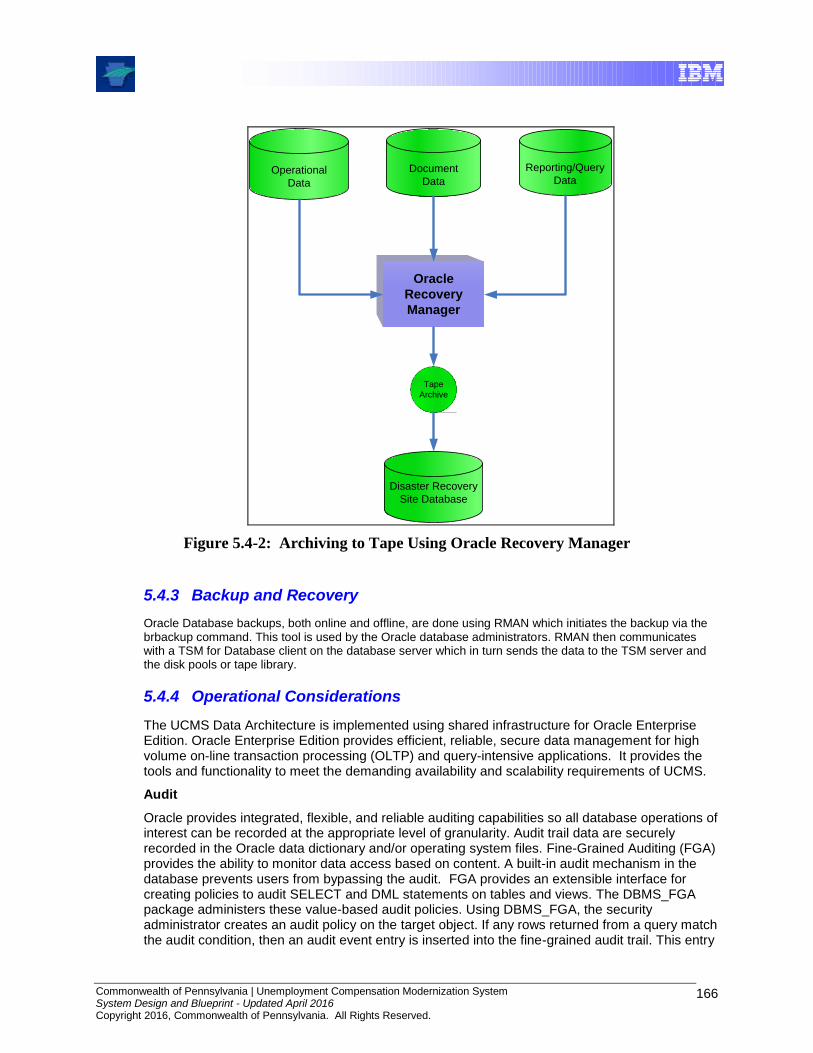
Commonwealth of Pennsylvania | Unemployment Compensation Modernization System System Design and Blueprint - Updated April 2016 Copyright 2016, Commonwealth of Pennsylvania. All Rights Reserved.
166
Tape
Archive
Oracle
Recovery
Manager
Reporting/Query
DataOperational
Data
Document
Data
Disaster Recovery
Site Database
Figure 5.4-2: Archiving to Tape Using Oracle Recovery Manager
5.4.3 Backup and Recovery
Oracle Database backups, both online and offline, are done using RMAN which initiates the backup via the brbackup command. This tool is used by the Oracle database administrators. RMAN then communicates with a TSM for Database client on the database server which in turn sends the data to the TSM server and the disk pools or tape library.
5.4.4 Operational Considerations
The UCMS Data Architecture is implemented using shared infrastructure for Oracle Enterprise Edition. Oracle Enterprise Edition provides efficient, reliable, secure data management for high volume on-line transaction processing (OLTP) and query-intensive applications. It provides the tools and functionality to meet the demanding availability and scalability requirements of UCMS.
Audit
Oracle provides integrated, flexible, and reliable auditing capabilities so all database operations of interest can be recorded at the appropriate level of granularity. Audit trail data are securely recorded in the Oracle data dictionary and/or operating system files. Fine-Grained Auditing (FGA) provides the ability to monitor data access based on content. A built-in audit mechanism in the database prevents users from bypassing the audit. FGA provides an extensible interface for creating policies to audit SELECT and DML statements on tables and views. The DBMS_FGA package administers these value-based audit policies. Using DBMS_FGA, the security administrator creates an audit policy on the target object. If any rows returned from a query match the audit condition, then an audit event entry is inserted into the fine-grained audit trail. This entry

Commonwealth of Pennsylvania | Unemployment Compensation Modernization System System Design and Blueprint - Updated April 2016 Copyright 2016, Commonwealth of Pennsylvania. All Rights Reserved.
167
includes all the information reported in the regular audit trail. See the Audit Records and Audit Trails section. Only one row of audit information is inserted into the audit trail for every FGA policy that evaluates to true. The extensibility framework in FGA also enables administrators optionally to define an appropriate audit event handler to process the event, for example by sending an alert page to the administrator.
System Management
Oracle Enterprise Manager (OEM) is the comprehensive management tool for managing the Oracle database and application environment. Oracle Enterprise Manager includes an easy-to-use centralized console, a rich set of management tools, and the extensibility to detect and solve problems that may arise. It also includes several administrative applications for performing day-today tasks for databases and applications, such as scheduling backup routines.
Oracle Enterprise Manager proactively monitors the health of all application components, the hosts that they run on, and the key business processes that they support. If a potential problem is spotted, Oracle Enterprise Manager’s diagnostic tools help to identify the root cause. In addition, Oracle Enterprise Manager helps visualize the impact of application performance in the context of business impacts,
The following four functional areas have tools that can be used:
Configuration Management: In order to achieve the necessary level of performance and availability to support the business objectives, applications must be configured properly.
Automatic Discovery: The first step in managing an application is to establish a detailed inventory of the application environment. Oracle Enterprise Manager collects detailed configuration information of all host systems and the installed software components across the environment. Data collected includes information on:
o Host hardware specs including number and clock speed of the CPUs,memory, hard disk and network information
o Operating system parameter settings, file system information and installed packages and patches
o Oracle software installed on the host including version and component information, patch sets and interim patches, as well as software configuration settings
o Third party software that are used in conjunction with Oracle technologies
o The relationships amongst applications and their infrastructure components
Policy Manager: Once the configurations are captured, the next step is to make sure that all the application components are set up properly. Enterprise-wide compliance with configuration policies can be automatically monitored. Policy compliance is evaluated continuously even as new targets come online. Administrators are immediately advised of any policy violations as they are identified, and suggestions are given as to how to address the violations.
Application Performance Management: administrators need to monitor the applications proactively for potential problems and fix problems at the first sign of trouble.
Proactive Monitoring and Alerting: Oracle Enterprise Manager continuously monitors key performance, usage and health indicators, and the occurrence of errors and warnings of the discovered application components. If any anomaly is found, Oracle Enterprise Manager alerts administrators to the potential problem, and can escalate the problems to other persons as necessary. In addition, features such as Automatic Root Cause

Commonwealth of Pennsylvania | Unemployment Compensation Modernization System System Design and Blueprint - Updated April 2016 Copyright 2016, Commonwealth of Pennsylvania. All Rights Reserved.
168
Analysis and Adaptive Thresholds increase the accuracy of the alerts by reducing false positives.
Dashboards: Dashboards provide the graphical visualization needed to achieve situation awareness for the health of applications when emergencies occur, or simply when the administrator needs to get an idea on how the application is performing. Increase performance and availability through proactive monitoring and alerting. Administrators may customize the dashboard pages by choosing the metrics and statistical functions for roll-ups.
Configuration Comparison: Oracle Enterprise Manager provides tools for comparing elements within the application environment, or between different snapshots of the application environment at great detail, allowing the administrator to quickly and easily pinpoint any potential differences. This helps to keep the components in the application environment synchronized and reduces "configuration drift". It also simplifies investigations into why components that are presumed to be identical may behave differently.
Interactive Transaction Performance Analysis: After an application performance problem is identified, the next step is to investigate the cause of the problem by locating transaction bottlenecks using captured execution data. This tool allows the administrator to:
o Look for all the transactions that are associated with a user.
o Identify the slowest running transactions.
o Get the aggregate breakdown on where time is spent in processing transactions, and the incremental CPU and memory consumption for the steps.
o Visualize the data graphically.
o Trace a particular transaction to identify bottleneck.
Service Level Management
Modeling Application Services: To enable monitoring of application services, administrators can define Service Level Objective, Availability Criteria, Key System Components, and Service Tests to model services as executed by end-users.
Monitor Service Performance and Usage: Service performance indicates the quality of service that applications are providing to their end-users. Service usage represents the user demand of the application in terms of its underlying systems components. Both performance and usage metrics are essential service level indicators because often, poor performance may be a result of an overload of demand for an underlying system resource. Oracle Enterprise Manager enables administrators to choose from a variety of out-of-box system metrics that can best represent key indicators for the performance and usage of applications,
Reporting Service Level Indicators: Oracle Enterprise Manager provides at-a-glance summary and detailed views of applications. Reports are provided both at the executive level for assessing overall service level compliance and making IT investment decisions, and at the administrative level for ensuring consistent delivery of high service levels.
Automation: Oracle Enterprise Manager provides automation capabilities that optimize resource consumptions and simplify the day-to-day management of the applications.
Patch Management: When a patch becomes available, Oracle Enterprise Manager evaluates the environment to see if the patch is applicable, and alerts the administrator on its availability.
Commonwealth of Pennsylvania | Unemployment Compensation Modernization System System Design and Blueprint - Updated April 2016 Copyright 2016, Commonwealth of Pennsylvania. All Rights Reserved.
169
Cloning: Oracle Enterprise Manager provides the ability to create a new application environment based on an existing working model. When rolling out an application, administrators may want to create a staging environment to assemble all the components and run system tests to ensure the proper integration of all the pieces.
Configuration Snapshot: Administrators often need to create new systems that are equivalent in performance to existing systems. One way to do this is to capture point in time information for an existing system. This information can then be used as a blueprint for creation of new systems. Oracle Enterprise Manager allows users to easily capture, store and view such information.
In addition, Tivoli Monitoring for Databases (ITM for Database) provides proactive monitoring and alerts on Oracle problems. Features of IBM Tivoli Monitoring for Databases include:
Thresholds – reference level for the monitor metrics; when exceeded, an indication of the threshold exceeded is given, such as by sending a Tivoli event, and/or email is sent, and/or a task is launched, and/or a page or phone call to the database administrator is made.
Parameters – specific resource names that are being monitored.
Occurrences – the number of times thresholds are exceeded before an indication of an event is sent.
Severity – the level of severity indicates the business impact of the event.
Schedule – time of day and day of week that the monitors will run.
The customized alerts that are generated appear in the monitoring tools:
Tivoli Omnibus – view alerts based upon data for a specific monitoring period and a ticket opened in ServiceNow.
ITM Console – view real-time data and up to 24 hours of historical data.
An enterprise Tivoli monitoring environment has already been established at DLI. UCMS enables the monitoring, logging of the UCMS Oracle databases and collection of performance data of the new UCMS servers to the existing Tivoli Data Warehouse to be used for reporting purposes.

Commonwealth of Pennsylvania | Unemployment Compensation Modernization System System Design and Blueprint - Updated April 2016 Copyright 2016, Commonwealth of Pennsylvania. All Rights Reserved.
170
6.0 Security & Privacy Architecture
6.1 Introduction
The section describes the UCMS Security Architecture. The purpose is to describe how the principles of information security are applied to UCMS, relative to applications and services. These principles are applied according to the identified business and information technology security requirements that have been gathered to date.
The UCMS Security Architecture is represented using the following architectural views:
Conceptual Architecture
The conceptual architecture identifies the different elements (process and technology) of the solution and their relationship to one another.
Logical Architecture
The logical architecture defines the required security building blocks (both process and technology), their functions, protocols and interfaces.
Physical Architecture
The physical architecture documents the hardware and software element relationships and boundaries that apply to the solution pipeline.
The Security Architecture for UCMS is based on the Business Policy and Process Infrastructure, and IT Security Services. Process flows naturally reflect the events and conditions in which information assets are acted on by users who have roles or by processes acting on behalf of users who have roles.
IT Security Services are already in place, but must be leveraged and extended in the architecture for UCMS. The CA eTrust products are an essential part of the DLI IAM Framework, for example, and the security architecture has to be flexible enough to support different deployment scenarios according to the various UCMS Functional Releases.
UCMS Solution Architecture
The initial solution models were used for this critical step in the design process in an effort to develop the solution architecture. Architectural decisions, principles and standards are used to drive the security architecture over the DLI IAM Framework. They further dictate what security subsystems to incorporate, which functions and mechanisms within each subsystem to deploy, where to deploy, and how the deployment is managed.
6.2 Security Design Principles
Applying security design principles to the security architecture design documents the structure, capabilities and components of the solution in a manner that is independent of specific vendor products and services. The appropriate architecture is directly related to understanding the DLI UCMS business and information technology security requirements and translating them into the appropriate security services.
The security design principles applicable to this architecture include:
Define the appropriate levels of security controls based on UCMS business objectives.
Maintain appropriate policies and standards to implement systems securely.

Commonwealth of Pennsylvania | Unemployment Compensation Modernization System System Design and Blueprint - Updated April 2016 Copyright 2016, Commonwealth of Pennsylvania. All Rights Reserved.
171
Define zones of control and the security requirements for information passage between them.
Leverage and extend existing security controls that impose minimal impact on COTS applications, creation of new applications and their deployment.
Provide security controls as a service to the DLI UCMS shared infrastructure. These controls include:
Utilize user identities consistently across all UCMS components as appropriate.
Obtain user identification with appropriate assurance of the validity of the identity.
Successfully identify and authenticate all users (including inter-application, intra-application and service IDs) before gaining access to protected UCMS assets and systems.
Trace credentials to a specific user.
Protect all credentials while at rest and in transit from unauthorized modification or unauthorized disclosure.
Define and implement an access control policy using Role Base Access Control to control access to DLI UCMS resources and services.
Manage security rules across the DLI UCMS network infrastructure in a consistent, understandable and enforceable manner.
Security should be transparent to user experience
Establish secure communication within DLI and between UCMS and other departments and partners. “Partner” in this context includes non-DLI and in some cases non-PA state agencies. Examples include the PA Department of Revenue (DoR) and the Internal Revenue Service (IRS).
Enable confidential storage and transmission of sensitive UCMS information.
Preserve integrity of data within files including application and system configuration files, message packets transmitted through the network and critical files and messages transmitted outside the DLI UCMS Infrastructure.
Assess all incoming traffic for reasonableness before it is processed by any application or system.
Use the existing DLI Identity and Access Management (IAM) Framework to manage security rules across the DLI UCMS network infrastructure in a consistent, understandable and enforceable manner.
Maintain security privileges, user identities and credentials.
Provide a service that collects information on security events, processes the information and delivers events and alerts to trigger automated and manual responses.
Maintain the integrity of systems so as to detect unauthorized modifications.
Correctly record and secure all security related events.
Provide security controls that are auditable.

Commonwealth of Pennsylvania | Unemployment Compensation Modernization System System Design and Blueprint - Updated April 2016 Copyright 2016, Commonwealth of Pennsylvania. All Rights Reserved.
172
6.3 Business-level Security Requirements
There are two identified business objectives of the security architecture:
1. To ensure that the desired UCMS IT business process flow yields correct and reliable results for the UCMS Functional Releases.
2. To ensure that the potential vulnerabilities and exception conditions within UCMS IT business process flows are addressed in ways that are consistent with the risk and UCMS management objectives.
The following general security requirements were identified that impact the security architecture:
UCMS applications and business services need to be secured because they provide access to confidential information
These services are accessible from outside the enterprise environment and have different security requirements for different access paths
UCMS service requests cross security domains in the enterprise and these policies need to be managed across security domains
UCMS wants to achieve Single Sign-On (SSO) for internal and external web based users to access their services. An objective would be to have a single Web-entry credential to maintain for each user, and minimize the need for maintenance of any second-level application sign-on credentials.
Access to UCMS services is allowed from business partners.
Composite services may exist that rely upon other services to complete its task
UCMS wants to audit access to service functions for meeting compliance goals
UCMS services are part of the business process and subscription to services needs to be managed efficiently
UCMS has a requirement to efficiently enable its partners and vendors to access UCMS services
6.4 Overarching Architectural Decisions
Higher-level architectural decisions have already been committed by the business, and form the basis for additional system requirements going forward.
An Enterprise Service Bus is implemented using webMethods. A Universal Discovery and Description (UDDI) service is used for service access point lookup on the bus.
Adobe Experience Manager (AEM) portal is the chosen mechanism for consolidated UI presentation to the user.
The enterprise identity and access management (IAM) solution is the CA IAM, which utilizes Active Directory as its LDAP store.
The authentication and authorization policy decision point solution is CA SiteMinder.
All input devices are browser based and must maintain a session cookie for the duration of a session.
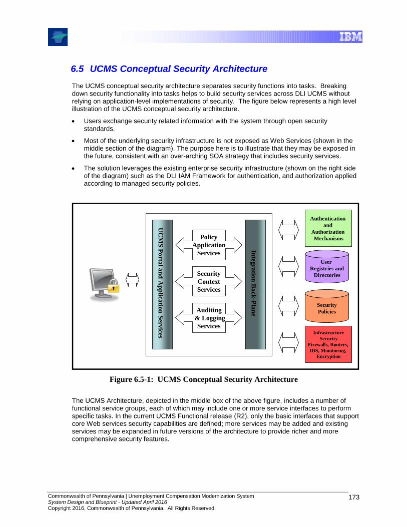
Commonwealth of Pennsylvania | Unemployment Compensation Modernization System System Design and Blueprint - Updated April 2016 Copyright 2016, Commonwealth of Pennsylvania. All Rights Reserved.
173
6.5 UCMS Conceptual Security Architecture
The UCMS conceptual security architecture separates security functions into tasks. Breaking down security functionality into tasks helps to build security services across DLI UCMS without relying on application-level implementations of security. The figure below represents a high level illustration of the UCMS conceptual security architecture.
Users exchange security related information with the system through open security standards.
Most of the underlying security infrastructure is not exposed as Web Services (shown in the middle section of the diagram). The purpose here is to illustrate that they may be exposed in the future, consistent with an over-arching SOA strategy that includes security services.
The solution leverages the existing enterprise security infrastructure (shown on the right side of the diagram) such as the DLI IAM Framework for authentication, and authorization applied according to managed security policies.
Policy
Application
Services
Security
Context
Services
Auditing
& Logging
Services
UC
MS
Po
rtal a
nd
Ap
plica
tion
Serv
ices
Integ
ratio
n B
ack
-Pla
ne
Authentication
and
Authorization
Mechanisms
Infrastructure
Security
Firewalls, Routers,
IDS, Monitoring,
Encryption
User
Registries and
Directories
Security
Policies
Figure 6.5-1: UCMS Conceptual Security Architecture
The UCMS Architecture, depicted in the middle box of the above figure, includes a number of functional service groups, each of which may include one or more service interfaces to perform specific tasks. In the current UCMS Functional release (R2), only the basic interfaces that support core Web services security capabilities are defined; more services may be added and existing services may be expanded in future versions of the architecture to provide richer and more comprehensive security features.
Commonwealth of Pennsylvania | Unemployment Compensation Modernization System System Design and Blueprint - Updated April 2016 Copyright 2016, Commonwealth of Pennsylvania. All Rights Reserved.
174
The following describes the service groups and their current member services.
Policy Services
This service group provides policy-based authorization and access control for Web Services and system resources. The services include:
Policy Decision Service – serves as an authorization authority for service providers that choose to use an external Policy Decision Point (PDP). This service accepts authorization queries and returns authorization decision assertions. The heart of the service is a policy evaluation engine, which applies policies based on a variety of inputs such as the target resource, the action or operation requested identity of the requester, etc.
Policy Retrieval Service – exposes security policies in eXtensible Access Control Markup Language (XACML) format. This service can allow service providers to retrieve policies for their resources, especially when they choose to implement their own PDP logic. This service can also be used by applications other than Web Services to retrieve stored resource policies (e.g. access control over portlets in a portal server). The CA SiteMinder Policy Server supports XACML policy interchange.
Policy Administration Service – This service uses XACML as a standard policy exchange format and can be used by management applications to compose, modify, and control policies. Depending on the access control model adopted in the domain, this service’s functionality may include Create, Read, Update, Delete (CRUD) operations for policy rules, rule sets, roles, permissions, security categories and compartment labels, among others.
Policy Enforcement Service – This service utilizes the centralized Policy Decision Service, and enforces policy decisions at the point of service interaction.
A Policy Subscription Service may also be defined, along with a related callback interfaces that allow interested parties to subscribe to and thereby receive real-time notifications on policy changes.
Security Context Services
In the UCMS service environment, security contexts are important in addressing service orchestrations and workflows. They may also help improve efficiency in interactive scenarios. For example, results of certain authentication and authorization steps may be performed only once for a series of consumer-provider interactions within a common security context.
Initially, the security context services consist of Web Single Sign-On (SSO), with a product-specific solution supported by CA SiteMinder and its distributed agents.
The Figure below highlights some important aspects of the security stack as generalized for SOA.

Commonwealth of Pennsylvania | Unemployment Compensation Modernization System System Design and Blueprint - Updated April 2016 Copyright 2016, Commonwealth of Pennsylvania. All Rights Reserved.
175
UCMS SOA
Application
Layer
UCMS SOA
Application
Layer
UCMS Standard
Networking
LayersPhysical
Protection
UCMS
Conceptual
Architecture
Application
Message
SecurityMessage security
Framework
Security
Information
Foundation
XML Security Data
Cryptographic
primitives
UCMS Common
Network Security
Approaches
Figure 6.5-2: Future SOA Security Context Services Superset for UCMS
Auditing and Logging Services
DLI UCMS auditing is also an important requirement for the security architecture. Two pieces of functionality are used: recording the service level activities (logging), and identifying anomalies (such as access violations or attacks) from those records. The logs may include:
Outbound message information (Identity, message ID, sending timestamp, host, target service, etc.)
Inbound message information (Identity, message ID, receiving timestamp, etc.)
Message signature verification (success / faults)
Certificate validation and status checking results (success / faults)
Policy decision results (permit / deny / indeterminate)
Invocation status (resource, action, success / faults)
The service interfaces defined by this UCMS Conceptual Architecture are desired specifications, not implementations. The actual implementations utilize additional technologies but the specifications must remain stable and interoperable. Going forward it is envisioned that the specifications will be driven by the collective efforts of various joint and shared initiatives and their requirements, while at the same time reflecting current industry standards and best practices.

Commonwealth of Pennsylvania | Unemployment Compensation Modernization System System Design and Blueprint - Updated April 2016 Copyright 2016, Commonwealth of Pennsylvania. All Rights Reserved.
176
6.6 UCMS Logical Security Architecture
The UCMS logical security architecture is based on the both the IBM SOA Security Reference Model and the UCMS Technical Solution Review Component Model. The logical security architecture contains three main components:
Current UCMS Business Security Services
Current UCMS Security Policy Infrastructure
Current UCMS IT Security Services
This is shown in the figure below.
Figure 6.6-1: UCMS Logical System Design Architecture
In this logical architecture:
Business Security Services leverage DLI UCMS IT Security Services and UCMS DLI Security Policy Infrastructure to build business-specific security services.
Security Policy Infrastructure not only provides security policy lifecycle management but also policy decision and transformation. Policies can be associated with service definitions and metadata and published back to service registries.
IT Security Services are the building blocks to provide security functions for UCMS services.
As shown above, there are multiple security enforcement points within the DLI UCMS environment. These enforcement points leverage consistent, coordinated, business-driven policies. The security infrastructure is implemented within the agency or via the Office of Administration using components such as SiteMinder, which are not configurable or accessible by UCMS developers. Interactions are limited to security integration with the UCMS solution.
Since the J2EE Functional Release applications are shared and reused, the applicable policies to address changing needs, heterogeneous application platforms and protocols (across business
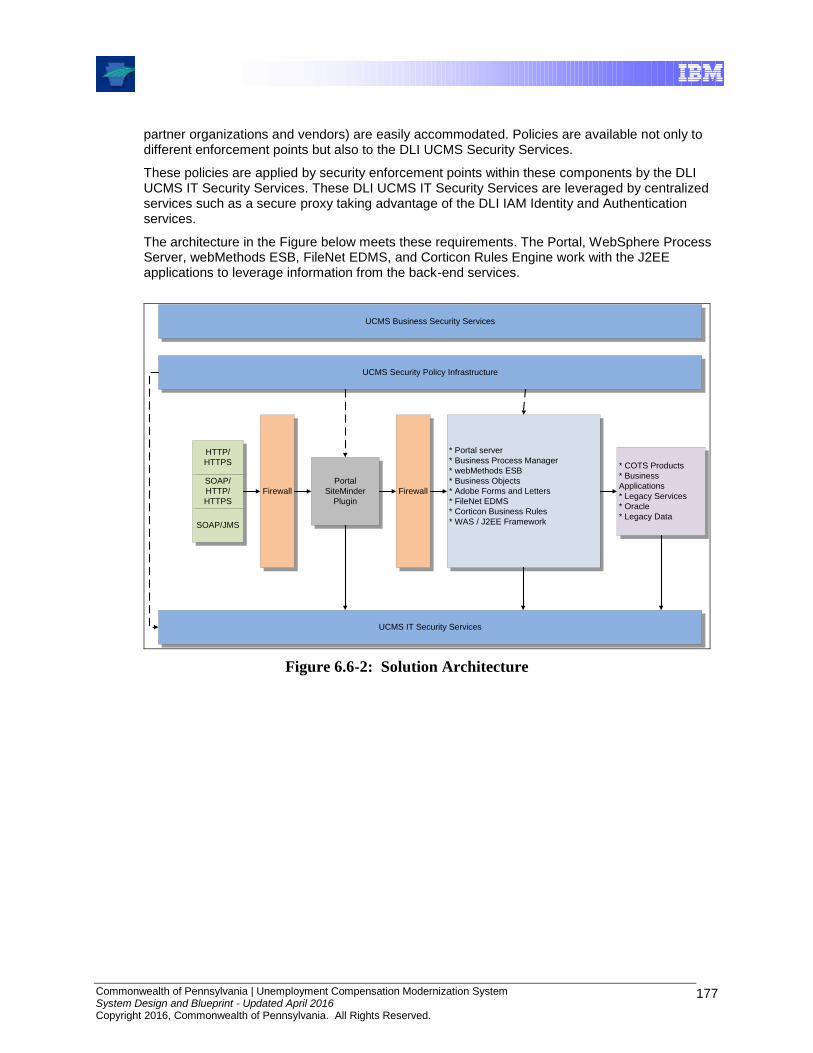
Commonwealth of Pennsylvania | Unemployment Compensation Modernization System System Design and Blueprint - Updated April 2016 Copyright 2016, Commonwealth of Pennsylvania. All Rights Reserved.
177
partner organizations and vendors) are easily accommodated. Policies are available not only to different enforcement points but also to the DLI UCMS Security Services.
These policies are applied by security enforcement points within these components by the DLI UCMS IT Security Services. These DLI UCMS IT Security Services are leveraged by centralized services such as a secure proxy taking advantage of the DLI IAM Identity and Authentication services.
The architecture in the Figure below meets these requirements. The Portal, WebSphere Process Server, webMethods ESB, FileNet EDMS, and Corticon Rules Engine work with the J2EE applications to leverage information from the back-end services.
UCMS Business Security Services
UCMS Security Policy Infrastructure
UCMS IT Security Services
HTTP/
HTTPS
SOAP/
HTTP/
HTTPS
SOAP/JMS
Firewall
Portal
SiteMinder
Plugin
Firewall
* Portal server
* Business Process Manager
* webMethods ESB
* Business Objects
* Adobe Forms and Letters
* FileNet EDMS
* Corticon Business Rules
* WAS / J2EE Framework
* COTS Products
* Business
Applications
* Legacy Services
* Oracle
* Legacy Data
Figure 6.6-2: Solution Architecture
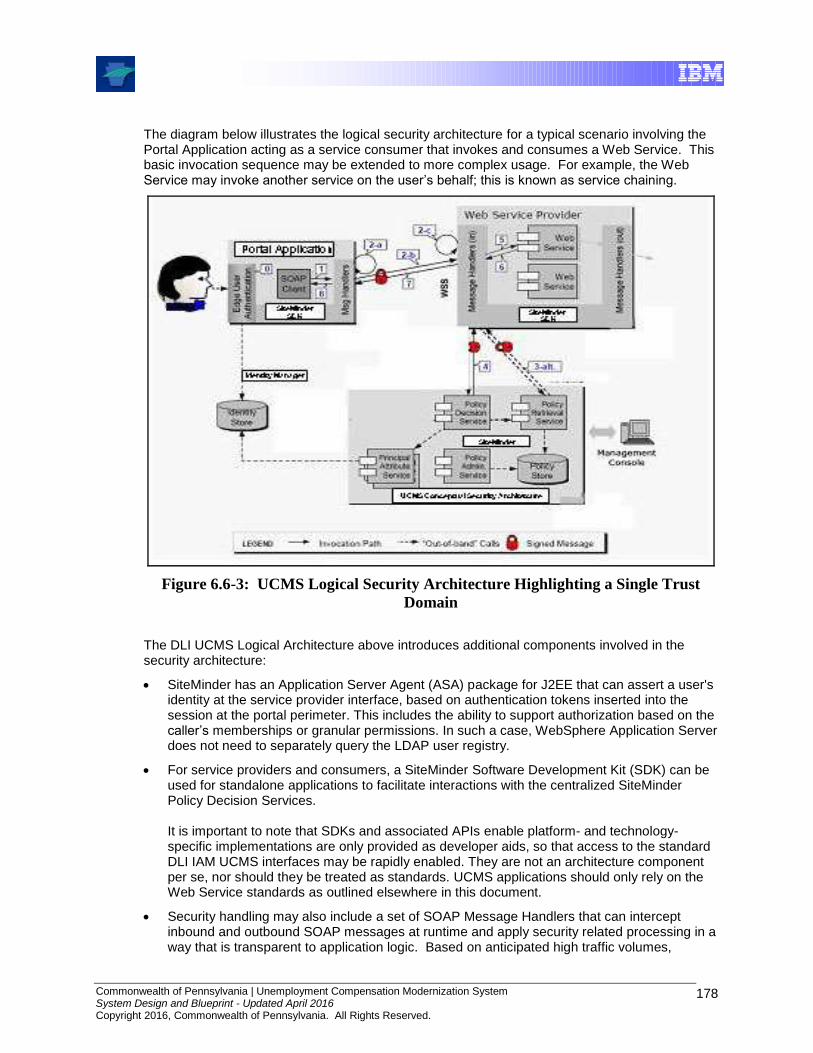
Commonwealth of Pennsylvania | Unemployment Compensation Modernization System System Design and Blueprint - Updated April 2016 Copyright 2016, Commonwealth of Pennsylvania. All Rights Reserved.
178
The diagram below illustrates the logical security architecture for a typical scenario involving the Portal Application acting as a service consumer that invokes and consumes a Web Service. This basic invocation sequence may be extended to more complex usage. For example, the Web Service may invoke another service on the user’s behalf; this is known as service chaining.
Figure 6.6-3: UCMS Logical Security Architecture Highlighting a Single Trust
Domain
The DLI UCMS Logical Architecture above introduces additional components involved in the security architecture:
SiteMinder has an Application Server Agent (ASA) package for J2EE that can assert a user's identity at the service provider interface, based on authentication tokens inserted into the session at the portal perimeter. This includes the ability to support authorization based on the caller’s memberships or granular permissions. In such a case, WebSphere Application Server does not need to separately query the LDAP user registry.
For service providers and consumers, a SiteMinder Software Development Kit (SDK) can be used for standalone applications to facilitate interactions with the centralized SiteMinder Policy Decision Services. It is important to note that SDKs and associated APIs enable platform- and technology-specific implementations are only provided as developer aids, so that access to the standard DLI IAM UCMS interfaces may be rapidly enabled. They are not an architecture component per se, nor should they be treated as standards. UCMS applications should only rely on the Web Service standards as outlined elsewhere in this document.
Security handling may also include a set of SOAP Message Handlers that can intercept inbound and outbound SOAP messages at runtime and apply security related processing in a way that is transparent to application logic. Based on anticipated high traffic volumes,
Commonwealth of Pennsylvania | Unemployment Compensation Modernization System System Design and Blueprint - Updated April 2016 Copyright 2016, Commonwealth of Pennsylvania. All Rights Reserved.
179
security related processing for a WebSphere Application Server to perform this type of processing may be deemed impractical. The primary purpose of depicting it this way is to highlight the complexity. Multiple message handlers can be “chained” together and can be configured at deployment time, which enables flexible and extensible security configurations. For example, an auditing handler may be added in front of the authentication and policy enforcement handlers, as illustrated in the below Figure: Note that “inbound” and “outbound” are relative terms. The same SOAP request is an outbound message to the service consumer but an inbound message to the service provider. Because a service provider can also be a consumer to other services, the SDK includes both inbound and outbound message handlers. We treat it here as a pure logical concept, not an implementation technique. Depending on the physical system architecture, the handler may map to a software component within the Web Service runtime, or a standalone application by itself.
6.6.1 Policy Application Footprint
Policy Services are applied across the outer tiers of entry into the UCMS environment. The footprint of agents and their consulted Policy Server is depicted in the figure below. The Policy Server is the Policy Decision Point (PDP), and each agent deployment represents a Policy Enforcement Point (PEP).
Specifically, the UCMS portal (entry-point at [1], [2]) and Partner-facing exchanges are protected as points of entry [4] by SiteMinder Web agents, for authentication. Authorization decisions are additionally applied at the web Portal [2] for first-level access, and then for application-specific internal accesses at the portlet delivery tier [3] running on WebSphere Application Server (WAS). Policy enforcement is provided at the portlet delivery layer by the SiteMinder ASA components, which provide WAS-native identity assertion and Java-standards-compliant authorization.
The Enterprise Service Bus supports both portal applications and external partners using file-based exchanges, and uses an instance of the SiteMinder Web agent or ASAs for verifying the SM credentials forwarded by its externally-facing counterparts. Another SM ASA agent deployment is shown as optionally applied at the Workflow Services platform.

Commonwealth of Pennsylvania | Unemployment Compensation Modernization System System Design and Blueprint - Updated April 2016 Copyright 2016, Commonwealth of Pennsylvania. All Rights Reserved.
180
Application Delivery tier
Local Business Logic
Shared Services
Security & IAM Services
Portal Web tier
IIS Server
Identity Repositories
OWCI Portal Services Policy Services Identity Management
Enterprise Service Bus
Partner-facing Web tier
SM Policy ServerPortal Definition
Portlet Services
SM Web Agent
SM ApplicationServer Agents
SM Web AgentOr ASA
CA IAM Services
Active Directory
Workflow Services
SM ApplicationServer Agents
Proxy Server
SM Web Agent
Data and Shared Support Services
[2]
[3]
[1]
[4]
Figure 6.6-4: Policy Decision and Enforcement Points
6.7 UCMS Physical Security Architecture
The recommended UCMS Physical Security Architecture is depicted below in relation to the existing DLI security architecture. The implemented physical security architecture, controlled by DLI/OIT, may or may not match the recommended architecture at any given time, and updates or improvements are solely at the discretion of DLI/OIT.
A security zone is a grouping of components that are subject to a defined set of security controls and mechanisms to ensure a designated level of security. The zones are grouped into regions with similar security requirements and levels of risk to ensure each zone is adequately segregated from other zones.
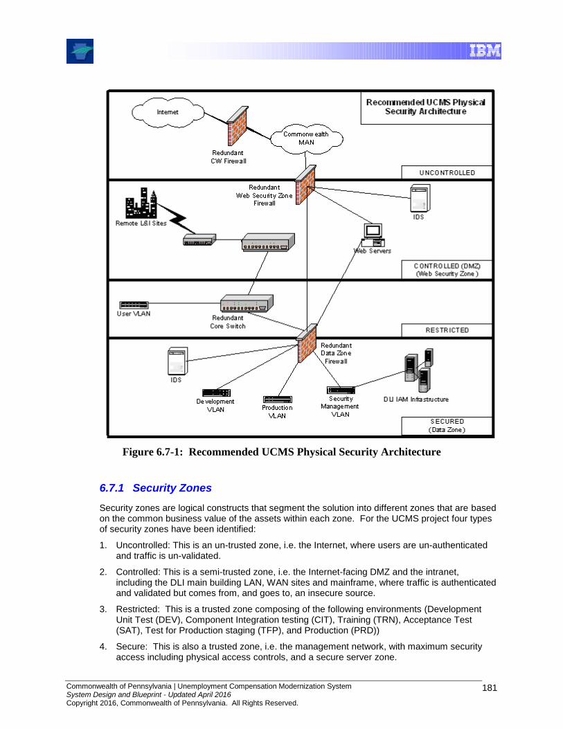
Commonwealth of Pennsylvania | Unemployment Compensation Modernization System System Design and Blueprint - Updated April 2016 Copyright 2016, Commonwealth of Pennsylvania. All Rights Reserved.
181
Figure 6.7-1: Recommended UCMS Physical Security Architecture
6.7.1 Security Zones
Security zones are logical constructs that segment the solution into different zones that are based on the common business value of the assets within each zone. For the UCMS project four types of security zones have been identified:
1. Uncontrolled: This is an un-trusted zone, i.e. the Internet, where users are un-authenticated and traffic is un-validated.
2. Controlled: This is a semi-trusted zone, i.e. the Internet-facing DMZ and the intranet, including the DLI main building LAN, WAN sites and mainframe, where traffic is authenticated and validated but comes from, and goes to, an insecure source.
3. Restricted: This is a trusted zone composing of the following environments (Development Unit Test (DEV), Component Integration testing (CIT), Training (TRN), Acceptance Test (SAT), Test for Production staging (TFP), and Production (PRD))
4. Secure: This is also a trusted zone, i.e. the management network, with maximum security access including physical access controls, and a secure server zone.
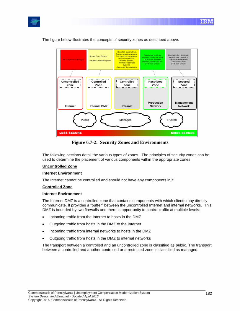
Commonwealth of Pennsylvania | Unemployment Compensation Modernization System System Design and Blueprint - Updated April 2016 Copyright 2016, Commonwealth of Pennsylvania. All Rights Reserved.
182
The figure below illustrates the concepts of security zones as described above.
No Components Deployed
Secure Proxy Servers
Intrusion Detection System
Interaction System Svcs,
Partner servicing systems,
Process services systems,
Business application
services systems,
Information services
systems,
Access services systems
Specialized restricted
zones for production, data,
backup and recovery,
business objects and pre-
production systems
IdentityMinder, SiteMinder
Repositories; network to
separate management
components from
production systems
LESS SECURE MORE SECURE
Public Managed Trusted
Internet
Uncontrolled
Zone
Internet DMZ
Controlled
Zone
Intranet
Controlled
Zone
Production
Network
Restricted
Zone
Management
Network
Secured
Zone
Figure 6.7-2: Security Zones and Environments
The following sections detail the various types of zones. The principles of security zones can be used to determine the placement of various components within the appropriate zones.
Uncontrolled Zone
Internet Environment
The Internet cannot be controlled and should not have any components in it.
Controlled Zone
Internet Environment
The Internet DMZ is a controlled zone that contains components with which clients may directly communicate. It provides a “buffer” between the uncontrolled Internet and internal networks. This DMZ is bounded by two firewalls and there is opportunity to control traffic at multiple levels:
Incoming traffic from the Internet to hosts in the DMZ
Outgoing traffic from hosts in the DMZ to the Internet
Incoming traffic from internal networks to hosts in the DMZ
Outgoing traffic from hosts in the DMZ to internal networks
The transport between a controlled and an uncontrolled zone is classified as public. The transport between a controlled and another controlled or a restricted zone is classified as managed.

Commonwealth of Pennsylvania | Unemployment Compensation Modernization System System Design and Blueprint - Updated April 2016 Copyright 2016, Commonwealth of Pennsylvania. All Rights Reserved.
183
Intranet Environment
Like the Internet DMZ, the DLI corporate intranet is a controlled zone that contains components that clients may directly communicate with. It provides a “buffer” to the internal networks.
Restricted Zone
Development & Unit Test Environment
DLI UCMS can have this network zone designated as restricted, that is, they support functions to which access must be strictly controlled, and direct access from an uncontrolled network is not permitted. As with an Internet DMZ, a restricted network is typically bounded by one or more firewalls and incoming and outgoing traffic may be filtered as appropriate.
Component Integration Test Environment
DLI UCMS can have this network zone designated as restricted, that is, they support functions to which access must be strictly controlled, and direct access from an uncontrolled network is not permitted. As with an Internet DMZ, a restricted network is typically bounded by one or more firewalls and incoming and outgoing traffic may be filtered as appropriate.
Training Environment
DLI UCMS can have this network zone designated as restricted, that is, they support functions to which access must be strictly controlled, and direct access from an uncontrolled network may or may not be permitted, as training needs dictate. As with an Internet DMZ, a restricted network is typically bounded by one or more firewalls and incoming and outgoing traffic may be filtered as appropriate.
Acceptance Test Environment
DLI UCMS can have this network zone designated as restricted, that is, they support functions to which access must be strictly controlled, and direct access from an uncontrolled network is not permitted. As with an Internet DMZ, a restricted network is typically bounded by one or more firewalls and incoming and outgoing traffic may be filtered as appropriate.
Test for Production Environment
DLI UCMS can have this network zone designated as restricted, that is, they support functions to which access must be strictly controlled, and direct access from an uncontrolled network is not permitted. As with an Internet DMZ, a restricted network is typically bounded by one or more firewalls and incoming and outgoing traffic may be filtered as appropriate.
The transport between a restricted and a controlled zone is classified as managed. The transport
between a restricted and a secured zone is classified as trusted.
Production Environment
DLI UCMS can have one or more network zones designated as restricted, that is, they support functions to which access must be strictly controlled, and direct access from an uncontrolled network is not permitted. As with an Internet DMZ, a restricted network is typically bounded by one or more firewalls and incoming and outgoing traffic may be filtered as appropriate.
Commonwealth of Pennsylvania | Unemployment Compensation Modernization System System Design and Blueprint - Updated April 2016 Copyright 2016, Commonwealth of Pennsylvania. All Rights Reserved.
184
Secured Zone
Management Environment
One or more DLI network zones may be designated as a secured zone. Access is only available to a small group of authorized staff. Access into one area does not necessarily give staff access to another secured area. The transport into a secured zone is classified as trusted.
6.8 Security Design
Security Design Objectives
UCMS has security requirements that are met in part by security services within the DLI IAM Framework and the UCMS Framework. These are detailed in the following sections, and include:
1. Identity services
2. Authentication and access control
3. Data confidentiality and integrity
4. Audit and logging
6.8.1 Identity Services
The identity services are composed of the following components:
Identity Foundation
Identity Provisioning
Identity Federation
Identity Foundation
There are two user repositories that are used in the UCMS solution: Active Directory (AD) server for CWOPA users, and a Managed Repository for Business Partners.
Identity Provisioning
In order to add, delete or modify individual account information, an identity provisioning solution is implemented. The CA Trust Identity Minder “Manager” which is a component of the DLI Identity and Access Management Framework is extensible and provides a secure, automated and policy-based user management solution. Please note that the CWOPA User Repository is a read-only replica.
Identity Provisioning guarantees that only the entitled identities with the correct attributes are provisioned to the directories or MS Active Directory Registries.
Identity Federation
The CWDS Federated Identity Management Architecture solution was defined as a joint CWDS and UCMS solution. Actual identity management, including identity federation, is implemented and controlled by DLI. This section provides basic information on the architecture that was proposed, however, DLI personnel are responsible for maintaining the accuracy of this information, and the text below may not reflect the as-is implementation.
For this solution design, Identity federation specifies a cross domain trust relationship, and implements a cross domain trust service with token mediation & identity mapping which is
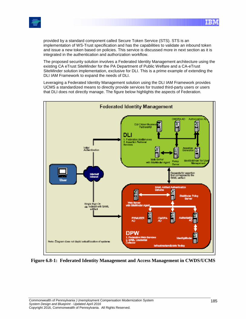
Commonwealth of Pennsylvania | Unemployment Compensation Modernization System System Design and Blueprint - Updated April 2016 Copyright 2016, Commonwealth of Pennsylvania. All Rights Reserved.
185
provided by a standard component called Secure Token Service (STS). STS is an implementation of WS-Trust specification and has the capabilities to validate an inbound token and issue a new token based on policies. This service is discussed more in next section as it is integrated in the authentication and authorization workflow.
The proposed security solution involves a Federated Identity Management architecture using the existing CA eTrust SiteMinder for the PA Department of Public Welfare and a CA-eTrust SiteMinder solution implementation, exclusive for DLI. This is a prime example of extending the DLI IAM Framework to expand the needs of DLI.
Leveraging a Federated Identity Management solution using the DLI IAM Framework provides UCMS a standardized means to directly provide services for trusted third-party users or users that DLI does not directly manage. The figure below highlights the aspects of Federation.
Figure 6.8-1: Federated Identity Management and Access Management in CWDS/UCMS
Commonwealth of Pennsylvania | Unemployment Compensation Modernization System System Design and Blueprint - Updated April 2016 Copyright 2016, Commonwealth of Pennsylvania. All Rights Reserved.
186
6.8.2 Authentication and Authorization Services
UCMS DLI IAM Technical Approach and Architecture
The core requirements for securing UCMS systems are as follows:
Authentication: verifying that users or processes that interact with the system are who they claim to be.
Access control: This refers to ensuring that authenticated parties have the necessary permission to access resources or perform operations with the least amount of difficulty.
Leverage the use of Single Sign-On using the shared DLI IAM Framework. This leverages the capability for identity assertion between SiteMinder Agents, from the Portal entry-point to the portlet-specific presentation layer.
Extend the capabilities of the DLI IAM Framework to support the UCMS J2EE technical solution with application level authorizations within a given portlet context.
SiteMinder has J2EE Application Server Agents (ASA) based on Java security standards that are specifically designed for WebSphere. The standards-compliant components meet Java Authentication and Authorization Service (JAAS) module requirements, and those of the more recent Java Authorization Contract for Containers (JACC) per JSR-115. A WebSphere-specific implementation for SiteMinder identity assertion is also included in the form of WebSphere’s Trust Association Interceptor (TAI).
HTTP/HTTPS clients can pass identity information to WAS by using the TAI. The TAI extracts this information and inserts the user’s identity as the session’s security “subject”, to make it available to the WAS container and application components that require it. WAS then queries the registry as usual, but does not need to re-validate the user's password. (If the user ID is not found in the registry, the assertion fails.) This provides a powerful mechanism for enabling the UCMS WebSphere Application Server to participate in a Web single sign-on domain.
UCMS Technical Solution Applications Authentication and Authorization
Process Server and other UCMS Technical solution applications have runtime components that are packaged as EAR files. All such components are candidates for securing their operations using the aforementioned TAI and other SiteMinder J2EE Application Server Agents (ASA) for WebSphere. The SiteMinder ASAs can support fine-grained access control, as well as authentication and authorization based on standards.
During installation of applications like FileNet, webMethods (Integration and Broker Applications) and Business Objects, roles are assigned for the administration of these UCMS applications. This same process is also supported under IBM’s WebSphere Global Security for Network Deployment. The Figure below highlights the extensibility of the DLI IAM SiteMinder Framework.

Commonwealth of Pennsylvania | Unemployment Compensation Modernization System System Design and Blueprint - Updated April 2016 Copyright 2016, Commonwealth of Pennsylvania. All Rights Reserved.
187
Figure 6.8-2: SiteMinder J2EE ASA “Agents”, SDK and SiteMinder TAI for WebSphere Application Servers
UCMS Applications End to End Security
IBM WebSphere Application Server supports three types of authentication for HTTP:
HTTP basic authentication
HTTP forms based authentication
HTTPS SSL-based client authentication
The Figure below highlights the UCMS end to end application security solution. HTTPS SSL-based client authentication is the preferred method of authentication for HTTP. HTTP Basic and HTTP forms based authentication should not be used in the UCMS environment.
Fire
wa
ll
HTTP
Or
Web Service
Client
Web Agent
or SPS
webMethods
ESB
WebSphere
Process Server
SiteMinder Policy
Server
Fire
wa
ll
SSL
SSL
Figure 6.8-3: UCMS Applications End to End Security
CA-eTrust SiteMinder Policy Server
SiteMinder SDK
Login Module SiteMinder TAI
eTrust SiteMinder WebAgent
Web Server or Secure Proxy server
CWOPA
FileNet, Business Objects, WAS Process
Server, Crystal Reports etc.
WAS Application Server
SPS with SiteMinder J2EE Agents
JAASJAC JACCEAD4J.DIAMOND
Commonwealth of Pennsylvania | Unemployment Compensation Modernization System System Design and Blueprint - Updated April 2016 Copyright 2016, Commonwealth of Pennsylvania. All Rights Reserved.
188
User Authentication (Login Services) Repositories
Users who need to access the application are registered through the security administration interfaces. Registered users have their login credentials maintained under Microsoft Active Directory. The CA eTrust SiteMinder solution integrates with the directory service to provide user authentication and enforce access control policies based on a user’s identity attributes and group membership.
For DLI, there are three separate user repository scopes, for managing:
Internal employees
Business partners
There is a self-service feature for registering and providing self-service management capabilities as part of the UCMS security architecture. Employees use their existing CWOPA user authentication, which integrates their UCMS login with their Windows NT LAN Manager (NTLM) authentication.
The UCMS CA Identity Manager is an integral part of the DLI IAM Framework and provides automated identity management services (creation, modification, and eventual deletion or suspension of user accounts and entitlements) for enterprise systems based upon the user’s relationship with the organization, whether they are an employee, contractor, customer or business partner, and the specific entitlement policies of the UCMS organization. The benefits are as follows:
Integrated identity administration and user provisioning
Delegated administration of user identities
User self-service of profiles and passwords
Integrated workflow
Integrated compliance support
The following steps give an overview of how CA eTrust SiteMinder Architecture works:
1. User attempts to access a protected resource through the website.
2. User is challenged for his credentials and presents them to the SiteMinder Web Agent.
3. The user’s credentials are passed to the policy server.
4. The user is authenticated against the appropriate user store.
5. The policy server evaluates the user’s entitlements and grants access.
6. User profile and entitlement information is passed to the application.
7. The user gets access to the secured application which delivers customized content to the user.
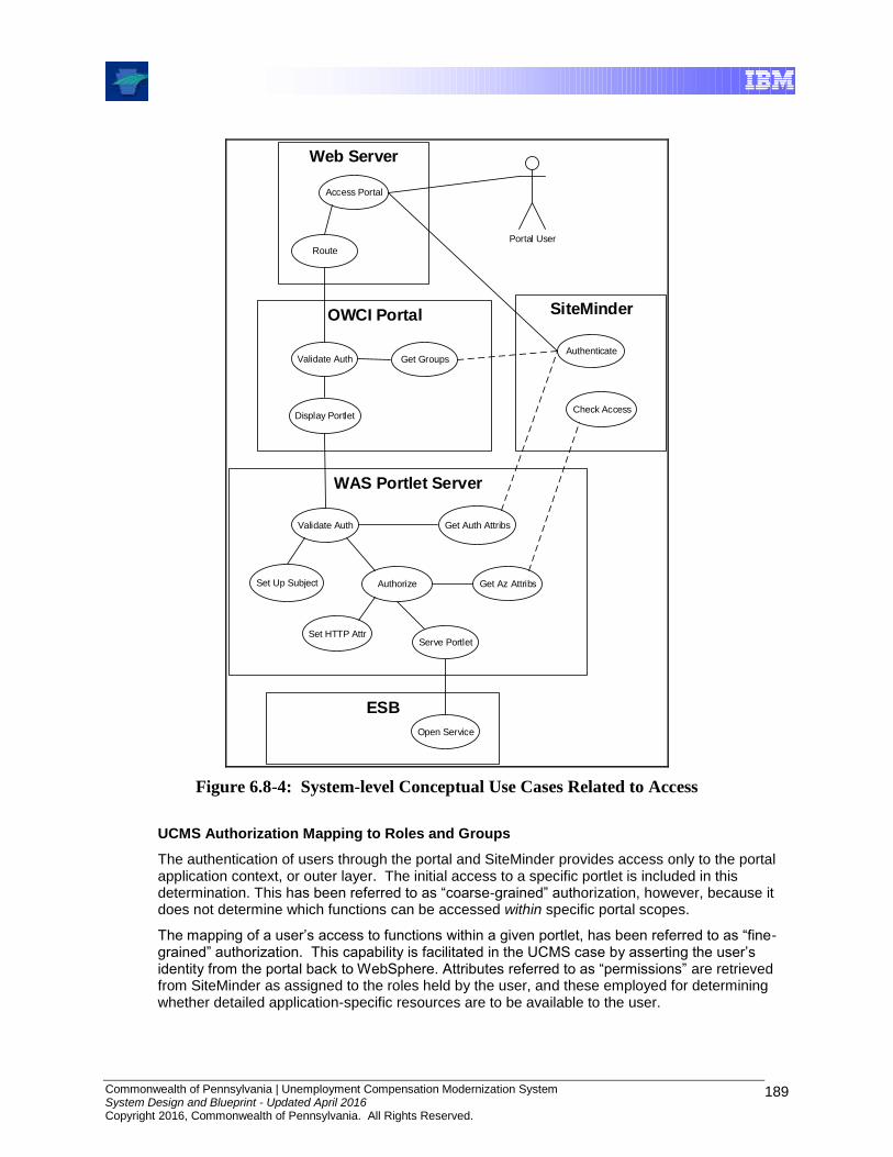
Commonwealth of Pennsylvania | Unemployment Compensation Modernization System System Design and Blueprint - Updated April 2016 Copyright 2016, Commonwealth of Pennsylvania. All Rights Reserved.
189
Web Server
Access Portal
Portal User
Route
OWCI Portal
Validate Auth
Display Portlet
SiteMinder
Authenticate
Check Access
Get Groups
WAS Portlet Server
Validate Auth
Authorize
Get Auth Attribs
Get Az Attribs
Serve Portlet
Set Up Subject
Set HTTP Attr
Open Service
ESB
Figure 6.8-4: System-level Conceptual Use Cases Related to Access
UCMS Authorization Mapping to Roles and Groups
The authentication of users through the portal and SiteMinder provides access only to the portal application context, or outer layer. The initial access to a specific portlet is included in this determination. This has been referred to as “coarse-grained” authorization, however, because it does not determine which functions can be accessed within specific portal scopes.
The mapping of a user’s access to functions within a given portlet, has been referred to as “fine-grained” authorization. This capability is facilitated in the UCMS case by asserting the user’s identity from the portal back to WebSphere. Attributes referred to as “permissions” are retrieved from SiteMinder as assigned to the roles held by the user, and these employed for determining whether detailed application-specific resources are to be available to the user.

Commonwealth of Pennsylvania | Unemployment Compensation Modernization System System Design and Blueprint - Updated April 2016 Copyright 2016, Commonwealth of Pennsylvania. All Rights Reserved.
190
6.8.3 Confidentiality and Integrity Services
Data Protection Services
The DLI UCMS Data Protection Services are concerned with data at rest. The data in transit and data in process of transformation in the UCMS environment are protected by the Message Protection Services. The UCMS Data Protection Services should also protect the cryptographic keys stored in the keystores, security configuration files for all of the UCMS applications (such as xml.config files), and the data stored in the database used for UCMS business applications and data access services. There are is an array of products available to protect the file systems that contain cryptographic keys and configuration files.
Message Protection Services
The Data and Message Protection services support the UCMS security requirements for the following:
Transport level security
Message integrity
Message confidentiality
Transport level security
The transport level security has to be applied to the following DLI UCMS communication channels:
To secure the UCMS communication channel for the service request, HTTPS between the components is implemented.
Communication between the Application Servers, webMethods Integration Server and Broker Services occurs using mutually authenticated SSL connections.
Communication to the DLI UCMS User Registries (MS Active Directories). The UCMS MS Active Directory LDAP Servers contain user identities, confidential information like passwords and other related identification information like application ids. To secure the communication between any component and the directories, the services have to be configured to use SSL to encrypt information from and to the LDAP services.
Communication between the SiteMinder Policy Server components. SiteMinder uses SSL for the communication to the SiteMinder components by default. There is no additional configuration needed. Only setting up the secure communication to the LDAP server needs additional configuration.
Communication between CA eTrust Identity Manager and
any adapters for SiteMinder
Secure Proxy Server [SPS]
AD Directory Services
CA eTrust Identity Manager may use specific adapters for the target system in provisioning of user identities. The communication between the adapters and the CA eTrust Identity Manager runtime is secured by using SSL.

Commonwealth of Pennsylvania | Unemployment Compensation Modernization System System Design and Blueprint - Updated April 2016 Copyright 2016, Commonwealth of Pennsylvania. All Rights Reserved.
191
Communication between the webMethods ESB services running on WebSphere Application Server, and mediation and event handling with any UCMS Middleware for messaging and data exchange are secured by using SSL.
Message level protection
A SOAP message travels from the service consumer to the service provider through intermediaries, UCMS middleware, and other applications along the message path. The intermediate UCMS middleware or application is capable of both receiving and forwarding SOAP messages. When an intermediary receives a SOAP message it processes the header entries of the message intended for it and must remove them afterwards before forwarding the message. It may also insert a new header entry for the next intermediary.
Secure Protocols like SSL/TLS assure the security of the message during transmission but as the messages can be received and forwarded by intermediaries, secure end-to-end communication cannot be guaranteed. Also transport level security has no effect on stored data. Once the message is received and decrypted, message level security is needed to protect the message.
The message path is not controlled by UCMS and the SOAP message has to be encrypted to guarantee that the message content is only visible to the service provider and service consumer.
The webMethods ESB service is required to validate the content of incoming requests from the internal service consumers. If messages from internal service consumers are signed and encrypted with certificates from DLI UCMS, the configuration for both end-points are the same.
6.8.4 Audit and Logging Services
The audit and logging security services capture information related to the ongoing operations that require authentication and authorization. They also provide a means to monitor compliance with the applicable security policies. The auditing services should be able to identify the individual user that was performing a transaction and their context of access.
The general security requirement for UCMS requires that every component has to be enabled for auditing and that the UCMS infrastructure has to be in place to submit, persistently store and report on audit data submitted as events using Tivoli System Management Tools.
The requirements for the audit and logging services include:
Provide mechanisms to submit, collect, persistently store and report on audit data submitted as events.
Provide methods to check compliance of the events to the individual security service policies.
The events which the UCMS audit and logging services need to capture include;
Identity Foundation adding, modifying, deleting, reading user through CA eTrust Identity Manager
Identity Provisioning through the DLI IAM Framework
Authentication (service consumer)
Authentication (Middleware, WAS, COTS application products)
Authorization and privacy (service consumer)
Authorization and privacy ( Intermediary servers like WAS Process Server & ESB)
Authorization and privacy ( Business Applications and Data Access services)
Authorization and privacy (Text, Oracle and legacy Data)

Commonwealth of Pennsylvania | Unemployment Compensation Modernization System System Design and Blueprint - Updated April 2016 Copyright 2016, Commonwealth of Pennsylvania. All Rights Reserved.
192
Message protection (ESB)
Message protection (ESB to any J2EE service component)
Data protection (Legacy Data, xml.config files, file systems)
(indirect case) message protection (service)
The UCMS Auditing and Reporting Service is the result of the efforts to unify IBM Tivoli auditing and reporting with the DLI IAM Framework, which consists of CA eTrust security products like SiteMinder and Identity Manager with a Secure Token Service, and any federated identity components.
For UCMS, the Auditing and Reporting Service for context auditing is defined as the process of maintaining detailed, secure logs of critical activities in the UCMS environment.
This includes the following items:
Security related critical activities (login failures, login success, unauthorized access to protected resources, modification of security policy, non-compliance with a specified security policy, service levels, and the health of security servers)
UCMS Business-related critical activities wage record transactions, tax transactions, and related accounting transactions.
UCMS critical activities related to content management (updates and deletions of critical documents: forms and letters, reports, reports on statistical analysis, wage records, tax data, accounting records, and CWA transactions.)
UCMS Role Based Access Control through delegated administration and Change Management; especially changes made by administrators.
The UCMS Auditing and Reporting Service collects the audit data from the enforcement point as well as from other platforms and security applications within the DLI UCMS environment.
In addition, the UCMS Auditing and Reporting Service provides access to subsidiary logs, log consolidation, log tuning, and the use of logs for current operations, for planning, for compliance, and for forensics.
Commonwealth of Pennsylvania | Unemployment Compensation Modernization System System Design and Blueprint - Updated April 2016 Copyright 2016, Commonwealth of Pennsylvania. All Rights Reserved.
193
7.0 Operational Architecture
7.1 Introduction
This document illustrates the Operational Model for the Commonwealth of Pennsylvania Unemployment Compensation Modernization System.
7.1.1 Identification
This document describes the operational model for the UCMS at the conceptual, specification and physical level.
7.1.2 Description
This document provides a representation of the network of computer systems, their associated peripherals and the systems software, middleware, and the application software they run.
The operational model includes:
Diagrams that show the topology and geographic distribution of the system, the definition of the nodes (computer platforms) and network connections, and where and how users and external systems interact with the system.
A detailed description of each node and identifies and classifies the software components that run on the node. Components are grouped into deployment units for ease of placement. The description includes the node’s availability, performance, security and other non-functional characteristics.
A detailed description of the networks that connect the nodes, together with their protocol layers and services.
A mapping matrix of deployment units to nodes, each deployment unit being a convenient grouping of components from the software architecture.
A description of the systems management strategy, including decisions about centralized vs. distributed managing stations, backup and recovery strategy, software distribution models and approach, change control, configuration management, and other systems management processes.
A description of middleware services and products and the key middleware choices (including security, Object Request Brokers, etc.).
Descriptions of walkthroughs, which describe the flow of a business activity from a user all the way through the system and back to the use, augmented by interaction diagrams, which show the flow of messages between nodes.
The specified level refers to a detailed specification of a computer platform or network. Technological limitations are fully taken into account but the detailed choice of technology is not made.
The physical level refers to the specific types of computers, networks, and software that make up the system.
The Operational Model develops from conceptual to specified, to physical, and at any one time, different parts of the description may be at different levels.
As the Operational Model is developed, detail is added within and between levels of abstraction and the network topology is restructured as the design passes from one level to the next.

Commonwealth of Pennsylvania | Unemployment Compensation Modernization System System Design and Blueprint - Updated April 2016 Copyright 2016, Commonwealth of Pennsylvania. All Rights Reserved.
194
7.1.3 Purpose
Different parts of an Operational Model are used for different purposes at different stages of its development.
At a conceptual level, an Operational Model is used:
As an early basis for design reviews and walkthroughs, including confirmation that the business problem is well articulated and that there is a viable IT solution.
As a way of dividing large problems so that each node can be worked on in relative isolation.
As the basis for early analysis of non-functional requirements such as performance, availability, and capacity, and including confirmation of the viability of a solution through specification of the expected non-functional characteristics of nodes and components.
To identify necessary technical, infrastructure, and other middleware components and subsystems.
As input to application design.
To contribute to early estimates of the cost of the infrastructure to be used both for budgeting and as part of the business case for the solution.
Later, an Operational Model at the specification level is used:
To document the distribution of application and technical subsystems (deployment units) on preliminary (conceptual or specified) nodes so they can ultimately be installed and run on physical computer systems.
As the basis for detailed design reviews and walkthroughs, prior to selecting products.
As a detailed technical specification against which alternative products can be evaluated or against which technology vendors can submit tenders.
As the basis for detailed prediction of performance, availability, and other service level characteristics
As the basis for a check that all the necessary business and technical functionality has been identified.
To allow application developers to refine and confirm their architecture and designs based on a detailed view of all the solution’s deployment units.
As the basis for cost estimates of the required infrastructure.
An Operational Model at the physical level is used as a blueprint for the acquisition, installation, and subsequent maintenance of the system.
The network design affects the application design, middleware selection, component placement, systems management and overall operational system control.
The systems management information in the Operational Model documents how elements at each location are managed and what extra systems management components and nodes are needed at each location. Selection of a systems management model determines:
The cost of operations management
The cost of software distribution
The complexity of system management tooling
Potential availability of the IT system (i.e., its ability to satisfy the service level requirements)
Commonwealth of Pennsylvania | Unemployment Compensation Modernization System System Design and Blueprint - Updated April 2016 Copyright 2016, Commonwealth of Pennsylvania. All Rights Reserved.
195
Middleware decisions effectively move functionality, which would otherwise be common to several applications, into a set of shared services. These services are purchased or are part of packaged applications.
7.2 System Topology Diagrams
This chapter describes the topology and geographic distribution of the UCMS system, the definition of the nodes (computer platforms) and network connections, and where and how users and external systems interact with the system.
Due to issues such as shared infrastructure, component upgrades, component migration to new products, and other factors, the topology diagrams can change frequently. For this reason, the reader is encouraged to obtain copies of the current topology diagrams from OIT, should there be a need for specific and accurate details of as-is implementation at a specific point in time.
7.2.1 Physical Infrastructure Topology Diagram
This section illustrates the physical infrastructure topology for the UCMS environment which includes the server, storage (SAN) and networking components.
.
7.2.1.1 Non-Production Physical Infrastructure
The following illustrates the physical infrastructure for the UCMS non-production environment. Environments included are Development (DEV) and Component Integration Testing (CIT.
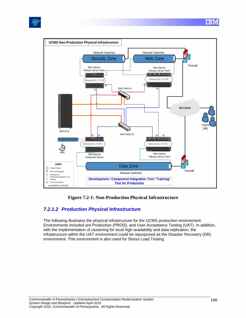
Commonwealth of Pennsylvania | Unemployment Compensation Modernization System System Design and Blueprint - Updated April 2016 Copyright 2016, Commonwealth of Pennsylvania. All Rights Reserved.
196
p5
p5
21
TotalStorage
SAN Fabric B
SAN Fabric A
IBM XIVs
S h a r e d [ D , I , T , T F ]
UCMS Non-Production Physical Infrastructure
IBM xSeries
VMware Server Farm
Private HMC Network
HMC
p5
p5
IBM pSeries
Partitioned Server
ESD
0
3
1
4
2
5
xSeries 460
ESD
0
3
1
4
2
5
xSeries 460
IBM xSeries
VMware Server Farm
S h a r e d [ D , I , T , T F ]
IBM xSeries
VMware Server Farm
ESD
0
3
1
4
2
5
xSeries 460
ESD
0
3
1
4
2
5
xSeries 460
S h a r e d [ D , I , T , T F ]
Users
(All)
DevelopmentIntegration
Training
UAT
Legend
D
I
T
Last Modified 11/24/2014
Development
Component Integration Test
Training
Firewall Cluster
Fiber SAN attached
Security Zone
Data Zone
DLI Core
Network Switches
Network SwitchesFirewall
Firewall
Web Zone
Network Switches
Development / Component Integration Test / Training/
Test for ProductionTF Test for Production
S h a r e d [ D , I , T , T F ]
Figure 7.2-1: Non-Production Physical Infrastructure
7.2.1.2 Production Physical Infrastructure
The following illustrates the physical infrastructure for the UCMS production environment. Environments included are Production (PROD), and User Acceptance Testing (UAT). In addition, with the implementation of clustering for local high availability and data replication, the infrastructure within the UAT environment could be repurposed as the Disaster Recovery (DR) environment. This environment is also used for Stress Load Testing.
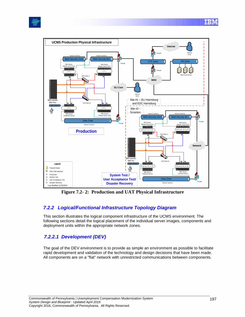
Commonwealth of Pennsylvania | Unemployment Compensation Modernization System System Design and Blueprint - Updated April 2016 Copyright 2016, Commonwealth of Pennsylvania. All Rights Reserved.
197
UCMS Production Physical Infrastructure
DevelopmentIntegration
UAT
Legend
P
S
U
Last Modified 11/25/2014
Production
System Test
User Acceptance Test
Firewall Cluster
Fiber SAN attached
p5
p5
21
TotalStorage
SAN Fabric B
SAN Fabric A
IBM DS8100,
IBM XIV
S h a r e d [ S , U , D ]
IBM xSeries
VMware Server Farm
HMC Network
HMC
p5
p5
S h a r e d [ S , U , D ]
IBM pSeries
Partitioned Server
ESD
0
3
1
4
2
5
xSeries 460
ESD
0
3
1
4
2
5
xSeries 460
IBM xSeries
VMware Server Farm
S h a r e d [ S , U , D ]
IBM xSeries
Discrete Servers
ESD
0
3
1
4
2
5
xSeries 460
ESD
0
3
1
4
2
5
xSeries 460
S h a r e d [ S , U , D ]
Data Zone
Network
Network SwitchesFirewall
Firewall
p5
p5
21
TotalStorage
SAN Fabric B
SAN Fabric A
IBM DS8300
IBM XIVs
[ P ]
IBM xSeries
VMware Server Farm
HMC Network
HMC
p5
p5
[ P ]
IBM pSeries
Partitioned Servers
ESD
0
3
1
4
2
5
xSeries 460
ESD
0
3
1
4
2
5
xSeries 460
IBM xSeries
VMware Server Farm
[ P ]
IBM xSeries
VMware Server Farm
ESD
0
3
1
4
2
5
xSeries 460
ESD
0
3
1
4
2
5
xSeries 460
[ P ]
Internal
Users
Web-Security Zone
Data Zone
DLI Core
Network Switches
Network SwitchesFirewall
Firewall
MANn
Internet
OA Zone
Web Portal Servers
External
Users
CTC Zone
Firewall
Firewall
Production
System Test /
User Acceptance Test/
Disaster Recovery
Site #1 – DLI Harrisburg
and EDC Harrisburg
Site #2 -
Scranton
D Disaster Recovery
Web-Security BLL
Network Switches
Web-Security Zone
Network Switches
Web-Security BLL
Network Switches
Figure 7.2- 2: Production and UAT Physical Infrastructure
7.2.2 Logical/Functional Infrastructure Topology Diagram
This section illustrates the logical component infrastructure of the UCMS environment. The following sections detail the logical placement of the individual server images, components and deployment units within the appropriate network zones.
7.2.2.1 Development (DEV)
The goal of the DEV environment is to provide as simple an environment as possible to facilitate rapid development and validation of the technology and design decisions that have been made. All components are on a "flat" network with unrestricted communications between components.
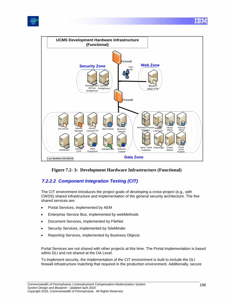
Commonwealth of Pennsylvania | Unemployment Compensation Modernization System System Design and Blueprint - Updated April 2016 Copyright 2016, Commonwealth of Pennsylvania. All Rights Reserved.
198
Last Modified 03/14/2016
UCMS Development Hardware Infrastructure
(Functional)
Managed and
SRTest
Bridgehead
CWOPA
BridgeheadMoveIT
DMZ FTP
Firewall
User
(All)
IBM FileNet
AEM
Dispatcher
Business
Objects
Identity
Manager
webMethodsSiteMinder Rational
Toolset
CWOPA
LDAP
MoveIT
Central FTPFile Server
WAS / AEM
Publisher
Adobe
LiveCycle
DataStage Oracle
RMAN
Business Process
ManagerFileNet
DBMS
Oracle
UCMS
RDBMS
Firewall
Rational
DBMS
Data Zone
Security Zone Web Zone
Figure 7.2- 3: Development Hardware Infrastructure (Functional)
7.2.2.2 Component Integration Testing (CIT)
The CIT environment introduces the project goals of developing a cross-project (e.g., with CWDS) shared infrastructure and implementation of the general security architecture. The five shared services are:
Portal Services, implemented by AEM
Enterprise Service Bus, implemented by webMethods
Document Services, implemented by FileNet
Security Services, implemented by SiteMinder
Reporting Services, implemented by Business Objects
Portal Services are not shared with other projects at this time. The Portal implementation is based within DLI and not shared at the OA Level.
To implement security, the implementation of the CIT environment is built to include the DLI firewall infrastructure matching that required in the production environment. Additionally, secure

Commonwealth of Pennsylvania | Unemployment Compensation Modernization System System Design and Blueprint - Updated April 2016 Copyright 2016, Commonwealth of Pennsylvania. All Rights Reserved.
199
communications links between external as well as internal components, including authorized and encrypted channels as necessary, are implemented within the CIT environment.
FileNet
ICC
AEM
DispatcherIdentity
Manager
webMethods
SiteMinder
UCMS CIT Hardware Infrastructure (Functional)
Last Modified 03/14/2016
Firewall
Firewall
Web Zone
Data Zone
Business
Objects
User
(All)
webMethods
Managed,
SRTest AD
and Bridgehead
FileNet
Content and App
Security Zone
CWOPA
AD
MoveIT
Central FTPFile Server
FileNet
Services
IISCWOPA
Bridgehead
MoveIT
DMZ FTP
WAS / AEM
Publisher
Adobe
LiveCycle
DataStage Oracle RMAN
Business
Process Manager
FileNet
DBMS
Oracle
UCMS
RDBMS
Figure 7.2- 4: CIT Hardware Infrastructure (Functional)
7.2.2.3 User Acceptance Testing (UAT) and Production (PROD)
The user acceptance test (UAT) infrastructure extends that of the CIT environment by adding availability solutions such as clustering for local high availability and data replication for Disaster Recovery (DR). Additionally, the UAT environment is sized to be equivalent in capacity to the production (PROD) environment to enable realistic load testing to be performed.
The PROD environment builds on UAT environment by adding the requirement that the recovery site is physically distant from the primary production facility.
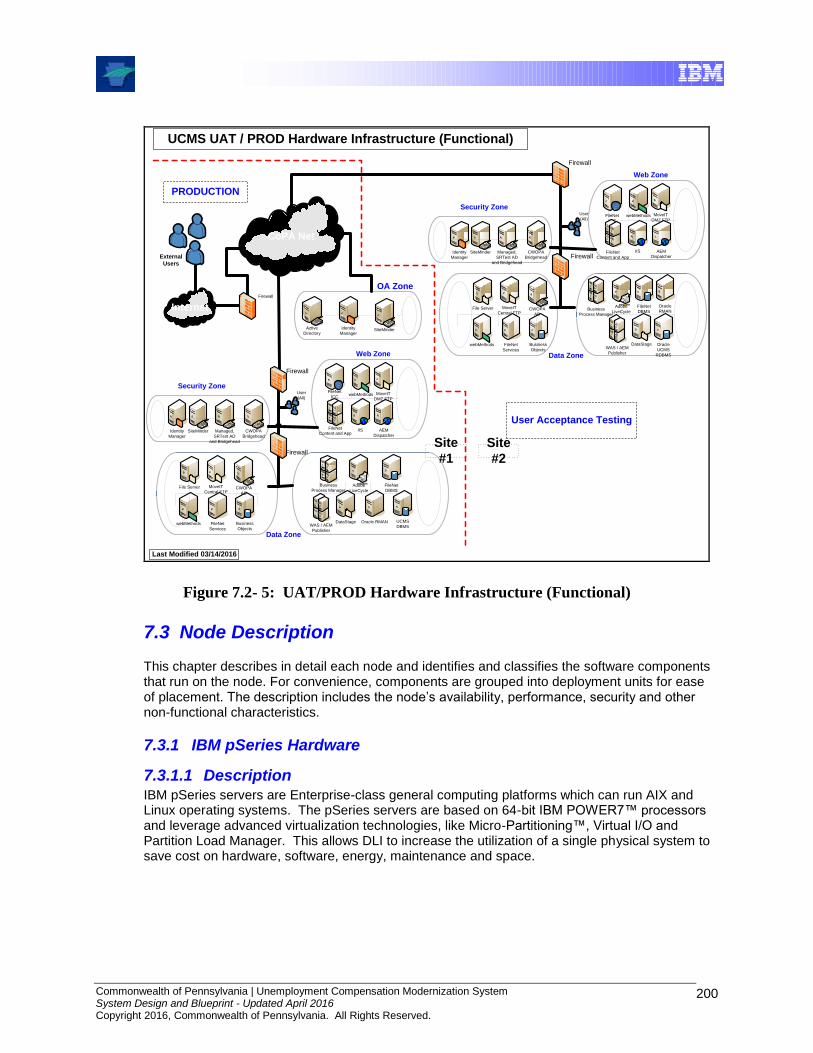
Commonwealth of Pennsylvania | Unemployment Compensation Modernization System System Design and Blueprint - Updated April 2016 Copyright 2016, Commonwealth of Pennsylvania. All Rights Reserved.
200
Identity
ManagerSiteMinder
Internet
UCMS UAT / PROD Hardware Infrastructure (Functional)
Last Modified 03/14/2016
PRODUCTION
User Acceptance Testing
OA Zone
CoPA Net
Firewall
External
Users
Site
#1
Site
#2
Active
Directory
FileNet
ICC
AEM
DispatcherIdentity
Manager
webMethods
SiteMinder
Firewall
Firewall
Web Zone
Data Zone
Business
Objects
User
(All)webMethods
Managed,
SRTest AD
and Bridgehead
FileNet
Content and App
Security Zone
CWOPA
AD
MoveIT
Central FTPFile Server
FileNet
Services
IISCWOPA
Bridgehead
MoveIT
DMZ FTP
WAS / AEM
Publisher
Adobe
LiveCycle
DataStage Oracle RMAN
Business
Process ManagerFileNet
DBMS
UCMS
DBMS
FileNet
ICC
AEM
DispatcherIdentity
Manager
webMethods
SiteMinder
Firewall
Firewall
Web Zone
Data Zone
Business
Objects
User
(All)webMethods
Managed,
SRTest AD
and Bridgehead
FileNet
Content and App
Security Zone
CWOPA
AD
MoveIT
Central FTPFile Server
FileNet
Services
IISCWOPA
Bridgehead
MoveIT
DMZ FTP
WAS / AEM
Publisher
Adobe
LiveCycle
DataStage
Oracle
RMANBusiness
Process Manager
FileNet
DBMS
Oracle
UCMS
RDBMS
Figure 7.2- 5: UAT/PROD Hardware Infrastructure (Functional)
7.3 Node Description
This chapter describes in detail each node and identifies and classifies the software components that run on the node. For convenience, components are grouped into deployment units for ease of placement. The description includes the node’s availability, performance, security and other non-functional characteristics.
7.3.1 IBM pSeries Hardware
7.3.1.1 Description IBM pSeries servers are Enterprise-class general computing platforms which can run AIX and Linux operating systems. The pSeries servers are based on 64-bit IBM POWER7™ processors and leverage advanced virtualization technologies, like Micro-Partitioning™, Virtual I/O and Partition Load Manager. This allows DLI to increase the utilization of a single physical system to save cost on hardware, software, energy, maintenance and space.

Commonwealth of Pennsylvania | Unemployment Compensation Modernization System System Design and Blueprint - Updated April 2016 Copyright 2016, Commonwealth of Pennsylvania. All Rights Reserved.
201
7.3.1.2 Deployment Units The table below illustrates the Deployment Unit which are hosted on the IBM pSeries hardware
Category / Level Conceptual Specification Physical
Processing Process/Rules Engine IBM WebSphere Process Server
IBM pSeries LPAR
Extract, Transform and Load DataStage IBM pSeries LPAR
Data Database(s) Oracle
IBM pSeries LPAR
Infrastructure Monitoring Tivoli Monitoring IBM pSeries LPAR
Job Scheduling $Universe IBM pSeries LPAR
Reporting Business Intelligence Business Objects Enterprise
IBM pSeries LPAR
Application J2EE Framework IBM Websphere Application Server
IBM pSeries LPAR
Hardware Hardware Management Console
IBM HMC IBM HMC
Virtual IO Server IBM VIO Server IBM pSeries LPAR
Operating System UNIX IBM AIX IBM pSeries LPAR
Backup/Recovery Server Image Backup/Recovery
IBM mksysb IBM pSeries LPAR
File Backup/Recovery IBM Tivoli Storage Manager
IBM pSeries LPAR
Database Backup/Recovery Oracle RMAN IBM pSeries LPAR
Management Content Management IBM FileNet IBM pSeries LPAR
Output Management Adobe Forms/Central IBM pSeries LPAR
7.3.2 IBM xSeries Hardware
7.3.2.1 Description The IBM xSeries hardware solution is responsible for providing a hosting environment for Windows-based applications. Complementing the IBM xSeries hardware platform is virtualization technology provided by VMware. VMware Infrastructure (VI) delivers a responsive IT environment - dynamic, efficient and available. Eliminating many of the constraints of traditional hardware, VMware Infrastructure allows for the following:
Implement Production Server Consolidation and Containment
Provide advanced business continuity protection at a lower cost
Deliver high availability for critical applications
Streamline Software Test & Development

Commonwealth of Pennsylvania | Unemployment Compensation Modernization System System Design and Blueprint - Updated April 2016 Copyright 2016, Commonwealth of Pennsylvania. All Rights Reserved.
202
7.3.2.2 Deployment Units The table below illustrates the Deployment Unit which are hosted on the IBM xSeries hardware. Depending on the environment the image maybe on a dedicated xSeries hardware or a VMware image.
Category / Level Conceptual Specification Physical
Presentation Application Web Portal AEM IBM xSeries Server or VMware image
Processing Enterprise Service Bus (ESB)
webMethods IBM xSeries Server or VMware image
FTP MoveIT IBM xSeries Server or VMware image
Infrastructure Virtualization VMware Virtual Infrastructure
IBM xSeries Server or VMware image
Virtual Machine Mgmt. VMware Virtual Center IBM xSeries Server or VMware image
Authentication Authentication Services Identity Manager IBM xSeries Server or VMware image
Policy and Roles Management
SiteMinder IBM xSeries Server or VMware image
Active Directory Microsoft IBM xSeries Server or VMware image
Reporting Reporting Business Objects IBM xSeries Server or VMware image
Operating System Microsoft Microsoft Windows 2010 IBM xSeries Server or VMware image
Management Content Management IBM FileNet IBM xSeries Server or VMware image
Development Source Control IBM Rational IBM xSeries Server or VMware image
Process Management IBM Rational IBM xSeries Server or VMware image
7.4 Connection Descriptions
This chapter describes in detail the networks that connect the nodes, together with their protocol layers and services.
7.4.1 Network Switches
Network switches are responsible for ensuring connectivity between servers within the same location or datacenter. They provide high speed access between nodes for data exchange and communication of components in the infrastructure. These switches provide connectivity utilizing the TCP/IP (Transmission Control Protocol/Internet Protocol) at speeds varying from 100 Megabits per sec. up to 1 Gigabit per sec. In addition to providing connectivity functions, the network switches are also capable of providing high availability and failover functions between multiple devices – which ensures continuous uptime for the networking environment.
Commonwealth of Pennsylvania | Unemployment Compensation Modernization System System Design and Blueprint - Updated April 2016 Copyright 2016, Commonwealth of Pennsylvania. All Rights Reserved.
203
Advanced features of these switches include:
Redundant Power and Cooling components
Redundant Supervisory Modules
Virtual LAN configuration (VLAN)
Switch Port Security
Performance Management and Reporting
The UCMS environment consists of networking routers and switches and firewall equipment including a firewall cluster controller and switches. The models utilized are installed and maintained by DLI, and the exact configuration can change as part of the shared infrastructure. The reader is encouraged to contact DLI networking personnel for the as-is equipment and configuration information if needed.
7.4.2 Network Firewalls and Routers
Network firewalls are responsible for ensuring security communication boundaries within the networking infrastructure. Not only do they control communication between nodes but also ensure appropriate and secure communication between deployment units and components. These devices are specifically designed for high network bandwidth throughput without compromise to performance latencies. In addition to providing secure communication, these devices also perform inter-site routing functions. With support of routing standard protocol such as RIP, RIPv2, OSPF, DVMRP, IGRP (Cisco) and BGP – these devices ensure intelligent and efficient connectivity between different sites and locations.
In addition, these devices also provide for high availability and load balancing capabilities, which ensure continuous connectivity between sites and locations.
7.4.3 Storage Area Network (SAN) Switches
Storage area networks (SAN) provide the facility to connect nodes/servers to the shared storage environment. These devices are responsible for ensuring secure and efficient access to application data stored on an external (to the node) shared storage devices. These switches provide connectivity utilizing protocols such as Fibre Channel (FCP), FCIP, iSCSI and Gigabit Ethernet speeds varying from 1 Gigabit per sec. up to 4 Gigabit per sec. In addition to providing basic storage connectivity, these switches also facilitate for long-distance replication, backup, and recovery. At the core of the DLI Storage Area Network are solutions are Cisco switches.
7.5 Node-Deployment Unit Mapping
This chapter contains matrices showing the mapping between deployment units and nodes. A deployment unit is a convenient grouping of components from the software architecture. By convention, nodes are shown in the columns (with the column headers as the node names) and the deployment units as rows.
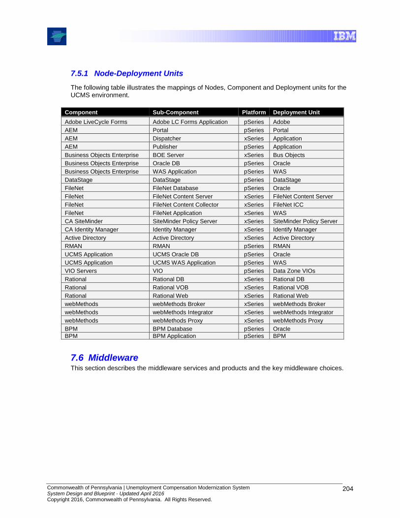
Commonwealth of Pennsylvania | Unemployment Compensation Modernization System System Design and Blueprint - Updated April 2016 Copyright 2016, Commonwealth of Pennsylvania. All Rights Reserved.
204
7.5.1 Node-Deployment Units
The following table illustrates the mappings of Nodes, Component and Deployment units for the UCMS environment.
Component Sub-Component Platform Deployment Unit
Adobe LiveCycle Forms Adobe LC Forms Application pSeries Adobe
AEM Portal pSeries Portal
AEM Dispatcher xSeries Application
AEM Publisher pSeries Application
Business Objects Enterprise BOE Server xSeries Bus Objects
Business Objects Enterprise Oracle DB pSeries Oracle
Business Objects Enterprise WAS Application pSeries WAS
DataStage DataStage pSeries DataStage
FileNet FileNet Database pSeries Oracle
FileNet FileNet Content Server xSeries FileNet Content Server
FileNet FileNet Content Collector xSeries FileNet ICC
FileNet FileNet Application xSeries WAS
CA SiteMinder SiteMinder Policy Server xSeries SiteMinder Policy Server
CA Identity Manager Identity Manager xSeries Identify Manager
Active Directory Active Directory xSeries Active Directory
RMAN RMAN pSeries RMAN
UCMS Application UCMS Oracle DB pSeries Oracle
UCMS Application UCMS WAS Application pSeries WAS
VIO Servers VIO pSeries Data Zone VIOs
Rational Rational DB xSeries Rational DB
Rational Rational VOB xSeries Rational VOB
Rational Rational Web xSeries Rational Web
webMethods webMethods Broker xSeries webMethods Broker
webMethods webMethods Integrator xSeries webMethods Integrator
webMethods webMethods Proxy xSeries webMethods Proxy
BPM BPM Database pSeries Oracle
BPM BPM Application pSeries BPM
7.6 Middleware This section describes the middleware services and products and the key middleware choices.

Commonwealth of Pennsylvania | Unemployment Compensation Modernization System System Design and Blueprint - Updated April 2016 Copyright 2016, Commonwealth of Pennsylvania. All Rights Reserved.
205
7.7 Walkthroughs
Section 9.2 describes the flow of various business or support activities from a user all the way through the system and back to the user. The purpose of this is to illustrate selected interactions between application nodes, to demonstrate the integration of core application components. Please note that the walkthrough scenarios were developed for the proof of concept environments, and may not necessarily represent the final application scenarios. Details on application scenarios are available in the module design documents described in earlier sections.
8.0 Systems Management Architecture
8.1 Introduction
DLI’s Office of Information Technology considers systems management part of its shared component infrastructure. The UCMS system supports and leverages the existing DLI systems management infrastructure and strategy. OIT’s current systems management strategy requires the architecture to support several customer service goals. These include, but are not limited to, the following:
Continue to establish and leverage common processes with appropriate levels of automation to ensure the effective, efficient delivery of IT services
Reduce total department operation costs through effective use of improved processes and technology
Improve service availability by proactively identifying and resolving conditions that could lead to potential problems (monitor, collect, evaluate and report enterprise events)
Enhance the functionality, integration, automation and scope of coverage for Server Farm operations and network processes
Incorporate quality assurance on data and performance standards
Ap
plicati
on
s
AE
M P
ort
al
IBM
WebS
phere
Applic
atio
n S
erv
er
Ou
tpu
t an
d P
rin
tin
g S
erv
ice
Adobe L
ifecycle
Fo
rms
File S
erv
ice
s
Win
dow
s 2
010 S
erv
er
Secu
rity
Serv
ices
SiteM
inder
Polic
y S
erv
er
Identity
Ma
nage
Active D
irecto
ry
Ob
ject
Se
rvic
es
webM
eth
ods B
roker
webM
eth
ods Inte
gra
tio
n
webM
eth
ods P
roxy
BI an
d R
ep
ort
ing
Se
rvic
es
Busin
ess O
bje
cts
Ente
rprise
Data
Man
ag
em
en
t S
erv
ice
Ora
cle
R
DB
MS
Tra
nsa
cti
on
Se
rvic
es
BIM
Busin
ess P
rocess M
anager
Cort
icon R
ule
s E
ngin
e
Co
nte
nt
Serv
ice
s
IBM
File
Net
Conte
nt S
erv
er
IBM
File
Net IC
C
Syste
m M
an
ag
em
en
t S
erv
ice
s
IBM
Tiv
oli
Om
nib
us.
IBM
Tiv
oli
Monitorin
g
IBM
Tiv
oli
Com
posite A
pplic
atio
n M
anager
IBM
Directo
r
API
External Environment

Commonwealth of Pennsylvania | Unemployment Compensation Modernization System System Design and Blueprint - Updated April 2016 Copyright 2016, Commonwealth of Pennsylvania. All Rights Reserved.
206
Increase the scope of common IT services to program areas
Increase management control to leverage information, common processes, skills, personnel resources and automation tools.
Review, consolidate, and document enterprise processes
Align data fields towards a single repository concept
Provide instructional documentation and conduct comprehensive training for program areas employees and OIT technical staff
Incorporate customer service satisfaction feedback reporting capabilities
Monitor compliance with service level agreements (SLA’s)
DLI currently has multiple systems management environments. Each in varying degrees supplies a wide array of systems management functions using multiple vendors’ software. The Tivoli software is used primarily for monitoring and ServiceNow for asset, change and incident/problem management. The processes that are followed to support the systems management architecture are defined in the Systems Management Plan work product.
Following is a high-level diagram of the major Tivoli tools and flows of the DLI Enterprise Tivoli Architecture that is used.

Commonwealth of Pennsylvania | Unemployment Compensation Modernization System System Design and Blueprint - Updated April 2016 Copyright 2016, Commonwealth of Pennsylvania. All Rights Reserved.
207
Tivoli Enterprise
Portal
Alarm Point
Alert
Transaction
PerformanceWebSphere
$UNetview
Tivoli Data
Warehouse
Tivoli Omnibus
Historical Analysis
Reporting
OS AIX &
Windows
Problem
Ticket
Oracle
DB
IBM Tivoli Monitoring Agents/
Infrastructure
Service
Now
Change
Requests
Asset
Management
Last Modified 11-24-2014
Figure 8.1- 1: DLI Enterprise Tivoli Tools for UCMS
As shown in the above figure, IBM Tivoli Monitoring management agents are deployed on the servers within the UCMS infrastructure. Situations are defined through a combination of metrics and thresholds to trigger, notify and solve problems. The alerts are then sent from the various monitoring management agents to the DLI Tivoli Omnibus. Omnibus correlates and filters duplicate or associated events. Based on the criticality of the events trouble tickets can be opened in DLI’s ServiceNow system and assigned to the appropriate support group defined in ServiceNow. Note that not all events passed into ServiceNow open tickets.
8.1.1 Management Consoles
The systems management environment can be observed and managed through several views:
Tivoli Enterprise Portal – graphic representation of monitored data
Tivoli Omnibus – displays all events collected
Tivoli NetView – graphic display of availability (up/down) of components in the environment
ServiceNow – displays change tickets, change tasks, and event/help desk tickets created automatically by an event or entered by help desk personnel.
Commonwealth of Pennsylvania | Unemployment Compensation Modernization System System Design and Blueprint - Updated April 2016 Copyright 2016, Commonwealth of Pennsylvania. All Rights Reserved.
208
8.1.2 Management Agents
The agents (referred to as managed systems) are installed on the system or subsystem requiring data collection and monitoring. The agents are responsible for data gathering and distribution of attributes to the monitoring servers, including initiating the heartbeat status. These agents test attribute values against a threshold and report these results to the monitoring servers. The tests are called situations.
Tivoli Enterprise Management Agents are grouped into five categories:
1. Operating System (OS) Agents - Operating System Agents retrieve and collect all monitoring attribute groups related to specific operating system management conditions and associated data. There are three primary operating system agents that are leveraged in the UCMS design:
Windows OS Agent
UNIX OS Agent
AIX Premium Agent
Log File Agent
Universal Agent - a special agent that leverages a full Application Programming Interface to monitor and collect data for any type of software.
2. Application Agents - Application Agents are specialized agents coded to retrieve and collect unique monitoring attribute groups related to one specific application. The monitoring groups are designed around an individual software application, and they provide in-depth visibility into the status and conditions of that particular application. There is one primary application agent that are utilized in the UCMS design:
WebSphere Application and WebSphere Process Servers
3. Composite Application Agents - allows monitoring and analysis of application transaction response time. It provides statistics of response time using instrumentation and robotic means and allows analysis and break down of response time into individual components to quickly pinpoint a response time problem. It can decompose transactions from robotic means simulating end users, tracking its execution in J2EE application servers.
ITCAM for Response Time Tracking
4. Application Diagnostics – provides a view the health of the WebSphere Application and Process server applications. This enables in-depth diagnostic information for specific application requests to identify the root cause of problems.
ITCAM for Application Diagnostics
5. Hardware Agents – provide specialized monitoring for the pSeries servers.
HMC – Hardware Management Console
CEC – Central Electronics Complex
Virtual I/O (VIOS) Premium Agent

Commonwealth of Pennsylvania | Unemployment Compensation Modernization System System Design and Blueprint - Updated April 2016 Copyright 2016, Commonwealth of Pennsylvania. All Rights Reserved.
209
Below is a table showing the implementation of the management agents by environment.
Environment Windows only Servers
Unix only Servers
Database only Servers
RTT – any server that the transaction traverses
Application
Diagnostics
Hardware
Development x x x x
CIT x x x x
TRN x x x x
TFP x x x x
UAT x x x x x x
PROD x x x x x x
8.2 Systems Management Component Model
Figure 8.2- 1: Systems Management Architecture

Commonwealth of Pennsylvania | Unemployment Compensation Modernization System System Design and Blueprint - Updated April 2016 Copyright 2016, Commonwealth of Pennsylvania. All Rights Reserved.
210
The architecture to support the server and transaction monitoring requirements for UCMS is described below. IBM Tivoli Monitoring software product supplies the following components:
Tivoli Enterprise Monitoring Server (TEMS)
Tivoli Enterprise Portal Server (TEPS)
Tivoli Enterprise Portal (TEP)
Tivoli Enterprise Management Agent (TEMA)
Tivoli Data Warehouse (TDW)
IBM Tivoli Composite Application Manager for Response Time Tracking (ITCAM for RTT) provides the following components:
Management Server
Store and Forward Agents
Management Agents
IBM Tivoli Composite Application Manager for Application Diagnostics (ITCAM for AD)
Management Server
Management Agents
The existing systems management environment provides these monitoring solution components:
Tivoli Omnibus
ServiceNow
Note: TMR and Tivoli Enterprise Data Warehouse (TEDW) and Tivoli gateways exist within the DLI infrastructure but are not used to manage the UCMS application.
8.3 IBM Tivoli Monitoring Components
8.3.1 Enterprise Monitoring Server (TEMS)
The TEMS (referred to as the monitoring server) is the initial component which begins building the IBM Tivoli Monitoring Services foundation. It is the key component on which all other architectural components depend directly. The TEMS acts as a collection and control point for alerts received from agents and collects their performance and availability data.
The TEMS is responsible for tracking the heartbeat request interval for all of the Tivoli Enterprise Management Agents connected to it.
The TEMS stores, initiates, and tracks all situations and policies. The TEMS is the central repository for storing all active conditions and short term data on every Tivoli Enterprise Management Agent. Additionally, the TEMS is responsible to initiate and track all generated actions that invoke a script/program on the Tivoli Enterprise Management Agent.
This Hub/Remote interconnection provides a hierarchical design allowing the Remote TEMS to control/collect its individual agent status and propagate the agent status up to the Hub TEMS.
This mechanism allows the Hub TEMS to maintain an infrastructure-wide visibility of the environment. The view gets passed to the Tivoli Enterprise Portal Server for pre-formatting, ultimately displaying within the Tivoli Enterprise Portal client.
Commonwealth of Pennsylvania | Unemployment Compensation Modernization System System Design and Blueprint - Updated April 2016 Copyright 2016, Commonwealth of Pennsylvania. All Rights Reserved.
211
When security validation is configured, the Hub TEMS is the monitoring server to manage operating system level userIDs.
8.3.2 Tivoli Enterprise Portal Server (TEPS)
The TEPS (referred to as the portal server) is a repository for all graphical presentation of monitoring data. The portal server database also consists of all the user ids and user access controls for the monitoring workspaces. The TEPS provides the core presentation layer which allows for retrieval, manipulation, analysis, and pre-formatting of data. It manages this access through user workspace consoles. The TEPS keeps a persistent connection to the Hub TEMS, and can be considered a logical gateway between the Hub TEMS and the Tivoli Enterprise Portal client. Any disconnection between the two components immediately disables access to the monitoring data used by the Tivoli Enterprise Portal client.
8.3.3 Tivoli Enterprise Portal (TEP)
The TEP client (referred to as the portal client) is a Java-based user interface which connects to the TEPS to view all monitoring data collections. It is the user interaction component of the presentation layer. The TEP brings all these views together in a single window so that it can be seen when any component is not working as expected. The client offers two modes of operation: a Java desktop client and http browser.
The following products currently have integrated interfaces into TEP:
IBM Tivoli Monitoring NetView
IBM Tivoli Omnibus
IBM Director
Products that may be added during the next phases of DLI’s Tivoli deployment:
IBM Tivoli Monitoring for Cluster Managers
IBM Tivoli Composite Application Manager for WebSphere
IBM Tivoli Composite Application Manager for SOA
IBM Tivoli Monitoring for Active Directory
IBM Tivoli Monitoring for Messaging and Collaboration
8.3.4 Tivoli Enterprise Management Agent (TEMA)
The agents (referred to as managed systems) are installed on the system or subsystem requiring data collection and monitoring. The agents are responsible for data gathering and distribution of attributes to the monitoring servers, including initiating the heartbeat status.
The agents test attribute values against a threshold and report these results back to the monitoring servers. An alert icon is displayed in the TEP when a threshold is exceeded or a value is matched. These tests are called situations.
8.3.5 ITM Firewall Gateway Feature
The Firewall Gateway feature in IBM® Tivoli® Monitoring V6.1 enables additional end-to-end connectivity options for use in environments with strict security policies concerning TCP/IP connection through firewalls. It allows the ITM V6.1 components to communicate with each other through a single port thus eliminating the need to open a range of ports.

Commonwealth of Pennsylvania | Unemployment Compensation Modernization System System Design and Blueprint - Updated April 2016 Copyright 2016, Commonwealth of Pennsylvania. All Rights Reserved.
212
8.3.6 Tivoli Data Warehouse (TDW)
The Tivoli Data Warehouse is the database storage that contains all the historical data collection. A Warehouse Proxy must be installed, to leverage the TDW function within the environment. In large scale deployments, a Tivoli Data Warehouse can be shared between monitoring installations.
8.4 ITCAM for Response Time Tracking Components
8.4.1 Management Server
The ITCAM (IBM Tivoli Composite Application Manager) management server provides centralized management and employs Web services to communicate with management agents at regularly scheduled intervals, called the upload interval. The default upload interval is once an hour. The management server includes the following pieces:
The user interface provides a way to interact with the monitoring software. The user interface is accessed through a Web browser.
Real time reports display collected performance data so the performance and availability of Web sites and Microsoft Windows applications can be assessed. The management server keeps a persistent record of the data collected by management agents for real-time and historical reports.
The event system notifies in real time about the status of monitored transactions through reports, e-mail notification, events sent to the IBM Tivoli, or the simple network management protocol (SNMP). Script can be run to respond to an event. The system generates application events when performance thresholds exceed or fall below acceptable limits. It generates system events for system errors and notifications. Recently generated events can be viewed at any time.
The Database stores monitor information, events, instance and hourly average monitoring data, and other information.
8.4.2 Store and Forward Agent
The store and forward agent provides bidirectional support for a secure connection from the management agents to the management server through a firewall by:
Enabling point-to-point connections between management agents and the management server.
Enabling management agents to interact with Store and Forward as if Store and Forward was a management server.
Routing requests and responses to the correct target.
Supporting SSL communications.
Supporting one-way communications through the firewall.
Commonwealth of Pennsylvania | Unemployment Compensation Modernization System System Design and Blueprint - Updated April 2016 Copyright 2016, Commonwealth of Pennsylvania. All Rights Reserved.
213
8.4.3 Management Agents
The management agents identify transactions that might need monitoring, collect performance data by running regularly scheduled listening and robotic monitors, and send generated events to the management server. Each listening and playback component is instrumented to retrieve data using ARM standards.
8.5 ITCAM for Application Diagnostics Components
8.5.1 Management Server
The management server is a distinct component of ITCAM (IBM Tivoli Composite Application Manager) for Application Diagnostics. It communicates to the Data Collectors within the WebSphere and J2EE Agents, and provides detailed diagnostic information through its user interface.
8.5.2 Management Agents
The Agent for WebSphere Applications component is installed on the WebSphere Application and Process servers in the UAT and Production environments.
8.6 Existing Solution Components
8.6.1 Tivoli Omnibus
The Tivoli omnibus is the event repository and correlation engine. Monitors are activated to “watch” the console for messages regarding the status of hardware components, operating systems, data base thresholds and application errors. Messages are collected here from the distributed monitors and categorized by DLI’s Omnibus server as critical, warning, or informational class alerts. Critical alerts for UCMS can be customized to alert an operator that action must be taken. For example, an alert could be scripted to include the actions to be taken upon the appearance of the alert – such as “call AIX technical on call person”, or “call the on call DBA”. This type of functionality would need to be developed and implemented at DLI. It is the responsibility of operations staff to respond to all alerts that appear on the Omnibus console, clearing a warning, noting the alerts that are fatal or critical and performing the appropriate actions.
Problem tickets are automatically generated when a critical Tivoli event is received by the Omnibus and forwarded to the ServiceNow system. Based on the information received, ServiceNow either opens a new or updates an existing problem ticket. If an update is made to the ticket, ServiceNow can also update the Omnibus event with the ticket’s status change.
8.6.2 IBM Tivoli NetView
The IBM Tivoli NetView component is an SNMP-based monitor used to check the up/down status of infrastructure devices, to gather network statistics such as bandwidth utilization and packet errors, and to process and forward error notifications called SNMP traps to Tivoli. It fulfills the UCMS network monitoring requirements in these areas.

Commonwealth of Pennsylvania | Unemployment Compensation Modernization System System Design and Blueprint - Updated April 2016 Copyright 2016, Commonwealth of Pennsylvania. All Rights Reserved.
214
8.6.3 ServiceNow
For the purpose of this architecture, the ServiceNow suite is treated as a single component that provides trouble ticketing, asset management, and change management functionality to DLI.
8.7 Backup and Recovery
The UCMS system leverages the existing DLI Server Farm Storage and Backup/Recovery architecture. Standard DLI enterprise retention policies and backup processes are used. Any deviation to these policies requires an exception request to be submitted through the UCMS Technical Change Control Process.
Tivoli Storage Manager (TSM), already installed at DLI, currently protects data from hardware failures and other errors by storing backup and archive copies of data on offline tape storage. Backups are copies of active online data which are stored on offline storage, both on-site and off-site for disaster recovery purposes. Should an online storage device fail, a data error occurs, or someone accidentally deletes a file, the offline copy of that data can be quickly copied (restored) to online storage. These restores can be requested via the ServiceNow change management process.
Fabric A
3494 Tape Library
3592 J Drives
Fabric B
HBG DS8300
HBG DS8100 (ESS3)
L
A
N
TSM
UCMS pSeries
Servers
ESD
0
3
1
4
2
5
xSeries 460
Cisco 9509 Director
UCMS xSeries
Servers
ESD
0
3
1
4
2
5
xSeries 460
Cisco 9509 Director
Tape
Disk
LAN
Legend
HBG XIV-1, XIV-2,
XIV-3
Figure 8.7- 1: DLI Backup Environment
8.7.1 Backup/Restore Strategy
There are five key areas outlined below that comprise the backup/restore strategy for the UCMS system. They include AIX system backups, Windows system backups, Incremental backups, and Oracle Database backups, and Disaster Recovery management.
Commonwealth of Pennsylvania | Unemployment Compensation Modernization System System Design and Blueprint - Updated April 2016 Copyright 2016, Commonwealth of Pennsylvania. All Rights Reserved.
215
8.7.1.1 AIX System Backups The purpose of a system backup is to recover the operating system in the event of a complete server failure and to recover servers during a disaster recovery. The current DLI architecture uses AIX Network Installation Management (NIM) to provide efficient and standardized AIX installations, software upgrades, and Operating System backups and restores to be managed from a centralized server. NIM provides the following functions:
Installation of new servers
Cloning of existing servers
Performing AIX Migrations and applying fixes to existing servers
Backup/Restore existing server operating systems to a centralized backup server (NIM server)
Weekly system backups are made on all AIX servers utilizing NIM. The most recent system backup remains online on the centralized backup server’s disk. Weekly tape backups of the centralized backup server are made to both a high speed tape drive, and also to TSM. A single set of these images remains off-site at VRI.
8.7.1.2 Windows System Backups UCMS leverages the DLI implementation of the TSM incremental backup system which allows full Bare Metal Restore of Windows server systems. After a base Windows server operating system is built and the TSM client is installed, full data recovery is performed, followed by restoration and merging of the Windows server registry, both using TSM. A restart of the server allows Windows to discover the changed server components and install the appropriate drivers. Reconfiguring the TCP/IP addresses completes the Bare Metal Restore. This methodology has been used to fully recover Windows servers to both similar and dissimilar equipment.
8.7.1.3 Incremental Backups Tivoli Storage Manager has the unique ability to manage data availability without requiring periodic full-system backups. TSM’s incremental, progressive backup capability eliminates the need for redundant, full-system backups while providing the ability to support the UCMS recovery scenarios.
TSM incremental backups are made of all non-database files, as is a standard at DLI today. Daily automated schedules will continue to backup all non-production and production servers and include all files that have changed since the previous night’s backup (except selected temporary files and database related files). Daily disaster recovery copies can be made.
The DLI architecture seeks to provide the UCMS system with the flexibility to avoid the unnecessary movement of redundant data across the network; as a result, the IBM solution provides consistent and quick recovery services from a centrally managed facility. The incremental-only paradigm reduces the additional CPU load on the client servers and additional network load by significantly reducing the amount of data that needs to be backed up in order to meet backup objectives.
UCMS can restore files in many different ways. For example, files or groups of files can be automatically restored from the most recent version, a previous point in time, or one that was five (5) versions old.
8.7.1.4 Oracle Database Backups TSM for Databases are used to backup all Oracle databases. Daily RMAN incremental backups (controlled by DLI DBAs) will continue to be used.
Commonwealth of Pennsylvania | Unemployment Compensation Modernization System System Design and Blueprint - Updated April 2016 Copyright 2016, Commonwealth of Pennsylvania. All Rights Reserved.
216
8.8 Change Control and Configuration Management
In collaboration with DLI, the existing DLI Change Control and Configuration Management processes are being refined to support the UCMS Production Environment and provide a template for use with other applications at DLI requiring high availability. Change control and configuration management in this section refers to the technical infrastructure environment not the application environment.
Change and Configuration Management does not exist in isolation. It has functional dependencies on other systems management processes such as Asset Management and Problem Management. By developing close interfaces with these processes the data accuracy of the configuration data is improved.
Change Management provides the interface to identify authorized changes to configuration Items and baselines. This process involves the planning, testing, validating and documenting changes that affect hardware and software components in the UCMS Environment.
Configuration Management provides the ability to identify, capture and organize key infrastructure configuration information, to provide accurate information to multiple processes and to maintain the data so that it remains current. Configuration changes are initiated by a change request, the result of a problem/incident ticket or a help desk ticket.
Asset Management identifies the costs, contracts, and purchase/lease data associated with assets and Configuration Items (CIs). There are many data areas that overlap with Configuration Management. In an integrated process, linking the two data repositories and allocating the redundant data elements to a single repository addresses the overlap. The configuration repositories and asset repositories are currently not completely integrated into a single repository at DLI. The UCMS systems leverages the existing repositories in place at DLI.
Problem Management provides the interface to identify those CIs changed to resolve a problem. Configuration Management provides Problem Management with data that can reduce problem resolution times.
The following diagram illustrates the ITIL (Information Technology Infrastructure Library) process for change and configuration management. ITIL is a process-based methodology that delivers a set of IT service management best practices.
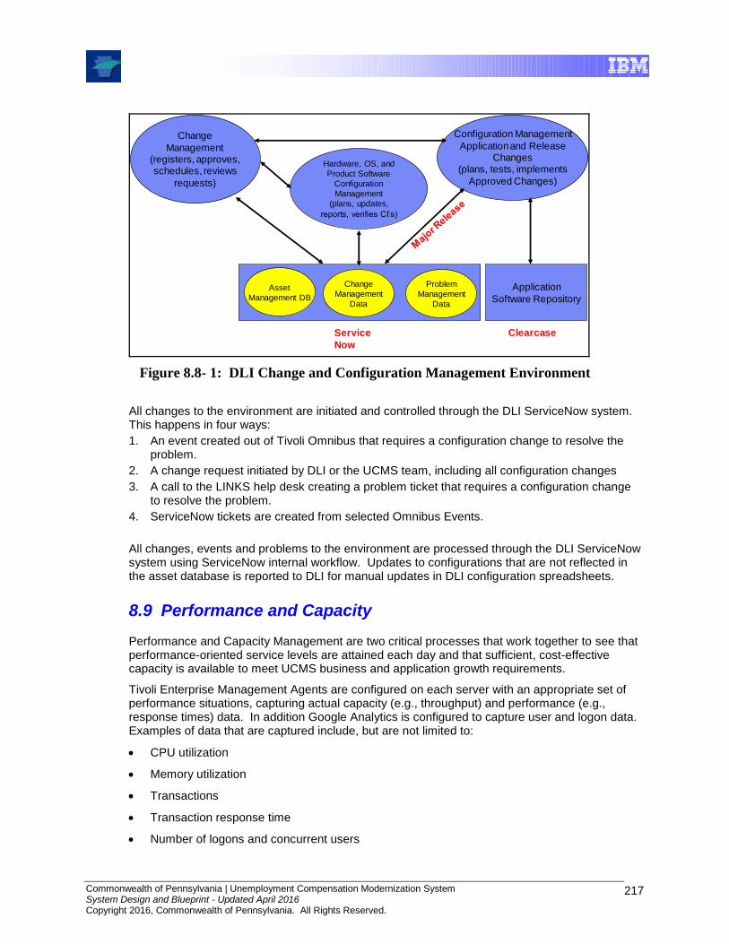
Commonwealth of Pennsylvania | Unemployment Compensation Modernization System System Design and Blueprint - Updated April 2016 Copyright 2016, Commonwealth of Pennsylvania. All Rights Reserved.
217
Application
Software Repository
Change
Management(registers, approves,schedules, reviews
requests)
Configuration Management
Application and ReleaseChanges
(plans, tests, implements
Approved Changes)
Hardware, OS, and
Product Software
Configuration
Management
(plans, updates,
reports, verifies CI’s)
Clearcase
Asset
Management DB
Change
Management
Data
Problem
Management
Data
Service
Now
Figure 8.8- 1: DLI Change and Configuration Management Environment
All changes to the environment are initiated and controlled through the DLI ServiceNow system. This happens in four ways:
1. An event created out of Tivoli Omnibus that requires a configuration change to resolve the problem.
2. A change request initiated by DLI or the UCMS team, including all configuration changes
3. A call to the LINKS help desk creating a problem ticket that requires a configuration change to resolve the problem.
4. ServiceNow tickets are created from selected Omnibus Events.
All changes, events and problems to the environment are processed through the DLI ServiceNow system using ServiceNow internal workflow. Updates to configurations that are not reflected in the asset database is reported to DLI for manual updates in DLI configuration spreadsheets.
8.9 Performance and Capacity
Performance and Capacity Management are two critical processes that work together to see that performance-oriented service levels are attained each day and that sufficient, cost-effective capacity is available to meet UCMS business and application growth requirements.
Tivoli Enterprise Management Agents are configured on each server with an appropriate set of performance situations, capturing actual capacity (e.g., throughput) and performance (e.g., response times) data. In addition Google Analytics is configured to capture user and logon data. Examples of data that are captured include, but are not limited to:
CPU utilization
Memory utilization
Transactions
Transaction response time
Number of logons and concurrent users

Commonwealth of Pennsylvania | Unemployment Compensation Modernization System System Design and Blueprint - Updated April 2016 Copyright 2016, Commonwealth of Pennsylvania. All Rights Reserved.
218
In real time, events are triggered and sent to Tivoli. Critical events are forwarded on to ServiceNow and a problem ticket opened and assigned.
Tivoli Data Warehouse is the common data repository to store actual performance and capacity results. This repository is used to develop reports for trend analysis, capacity planning and to assist in root cause analysis to determine pro-active steps to avoid interruptions to committed service levels.
There are four major components that make up the infrastructure for the Tivoli Data Warehouse.
The monitoring agents: These are responsible for the collection of the detailed metric data from a monitored system or application.
The Tivoli Warehouse Proxy: This agent is responsible for receiving this detailed metric data from the agents and inserting it into the Tivoli Data Warehouse.
The Tivoli Summarization and Pruning agent: This agent is responsible for summarizing the detailed data within your Tivoli Data Warehouse and pruning data that is no longer required.
The Tivoli Data Warehouse: This is the data warehouse itself that is responsible for storing and providing the detailed and summarized data for all captured agents.
8.10 Other Systems Management Processes
Multiple integration points exist between the processes that exist in IT Operational Management. The following figure gives a high-level overview of the integration points that exist between the various processes.

Commonwealth of Pennsylvania | Unemployment Compensation Modernization System System Design and Blueprint - Updated April 2016 Copyright 2016, Commonwealth of Pennsylvania. All Rights Reserved.
219
ESM Process Integration
Change
Management
Process
Help Desk/
Problem Process
Backup/Recovery
Process
Asset/
Configuraiton
Management
Process
Service Level
Management
Process
Event
Management
System
Performance/
Capacity
Management
Process
Security Process
Release/Software
Distribution
Process
Availability
Management
Process
Figure 8.10- 1: ESM Process Integration

Commonwealth of Pennsylvania | Unemployment Compensation Modernization System System Design and Blueprint - Updated April 2016 Copyright 2016, Commonwealth of Pennsylvania. All Rights Reserved.
220
9.0 Appendices
9.1 Glossary of Acronyms
Acronym Acronym Description
API Application Programming Interface
ASA Application Server Agent
ASM Automatic Storage Management
BIOS Business Innovation & Optimization Services
BPEL Business Process Execution Language
BPEL4WS Business Process Execution Language for Web Services
CBE Common Base Event
CBL Common Business Library
CIFS Common Internet File System
COTS Commercial off-the-shelf software or hardware product
CRM Customer Relationship Management
CRUD Create, Read, Update, Delete
cXML Commerce XML
DHCP Dynamic Host Configuration Protocol
DI Dependency Injection
DMZ Demilitarized Zone
DNS Domain Name System
EAD4J Enterprise Application Development for Java
ebXML Electronic Business using XML
EDI Electronic Data Interchange
EJB Enterprise Java Bean
ERP Enterprise Resource Planning
ESB Enterprise Service Bus
ESP External Service Provider
ETL Extract, Transform, Load
FTP File Transfer Protocol
FTPS FTP over SSL
GUI Graphical User Interface
HTML Hypertext Markup Language
HTTP Hypertext Transfer Protocol
HTTPS HTTP over SSL
IDOC Intermediate Document
IoC Inversion of Control
ISP Internal Service Provider
ITIL Information Technology Infrastructure Library
J2EE Java 2 Platform, Enterprise Edition
JAXB Java Architecture for XML Binding
JCA Java Connector Architecture

Commonwealth of Pennsylvania | Unemployment Compensation Modernization System System Design and Blueprint - Updated April 2016 Copyright 2016, Commonwealth of Pennsylvania. All Rights Reserved.
221
Acronym Acronym Description
JDBC Java Database Connectivity
JDK Java Development Kit
JMS Java Message Service
JMS Java Messaging Service
JMX Java Management eXtensions
JNDI Java Naming and Directory Interface
JSF Java Server Faces
JSP Java Server Pages
JSR Java Specification Request
JSTL Java Server Pages Standard Tag Library
LAN Local Area Network
LDAP Lightweight Directory Access Protocol
LPAR Logical Partition
LTPA Lightweight Third Party Authentication
MAN Metropolitan Area Network
MDB Message Driven Bean
MOM Message-Oriented Middleware
MQ Messaging Queuing
MVC Model View Controller
NFR Non-Functional Requirement
OAG Open Applications Group
OCR Optical Character Recognition
ODMG Object Data Management Group
OLTP OnLine Transaction Processing
OMI Open Management Interface
PKI Public Key Infrastructure
POJO Plain Old Java Object
RBAC Role Based Access Control
RPC Remote Procedure Call
S/MIME Secure / Multipurpose Internet Mail Extensions
SAML Security Assertion Markup Language
SAN Storage Area Network
SCA Service Component Architecture
SDK Software Development Kit
SMTP Simple Mail Transfer Protocol
SNMP Simple Network Management Protocol
SOA Service-Oriented Architecture
SOAP Simple Object Access Protocol
SOMA Service-Oriented Modeling Architecture
SM SiteMinder
SPS Secure Proxy Server
SSL Secure Sockets Layer
STS Secure Token Service
SWAM Simple WebSphere Authentication Mechanism

Commonwealth of Pennsylvania | Unemployment Compensation Modernization System System Design and Blueprint - Updated April 2016 Copyright 2016, Commonwealth of Pennsylvania. All Rights Reserved.
222
Acronym Acronym Description
TSL Transport Layer Security
UDDI Universal Description, Discovery and Integration
UML Universal Modeling Language
URL Uniform Resource Locator
W3C World Wide Web Consortium
WAI Web Accessibility Initiative
WAN Wide Area Network
WAR Web Application Archive
WAS WebSphere Application Server
WCAG Web Content Accessibility
WSDL Web Services Description Language
WS-I Web Services Interoperability Organization
XACML eXtensible Access Control Markup Language
XML eXtensible Markup Language
XSD XML Schema Definition
XSL eXtensible Stylesheet Language
9.2 Business and Support Walkthroughs
9.2.1 Business Walkthroughs
As depicted in the figure below, this section provides a walkthrough of various core components, including:
The webMethods Enterprise Service Bus
FileNet document and image management
Security authentication and authorization (SiteMinder)
User Interface (web Portal)
InfoView (Business Objects)
Task Management (IBM Business Process Manager)
Business Roles (Corticon Rules Engine, a WebSphere application)
Application Integration (WebSphere Application Server and J2EE framework)
Output Management (Business Objects, Adobe)
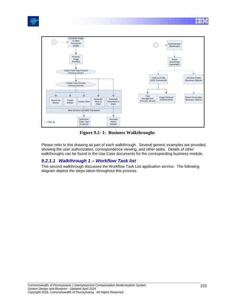
Commonwealth of Pennsylvania | Unemployment Compensation Modernization System System Design and Blueprint - Updated April 2016 Copyright 2016, Commonwealth of Pennsylvania. All Rights Reserved.
223
Web Services via J2EE Framework
Generate Image
& Index
Documents
(DOR)
Process
Image
(FileNet)
Associate
Document to
Claim
Generate
Notice
(Adobe)
Search for
Worker
Create
WorkerCreate Claim
Associate
Party to
Claim
Determine
Claim Type
(Corticon)
Create Case Process
(Process Server)
Intake Claim App Process
(Process Server)
ESB
TaskList Portlet
(J2EE Framework)
Portal
HomePage
(Aqualogic)
Task
Management
(Process Server)
Authentication
(SiteMinder)
Image Retrieval
(FileNet/J2EE)
InfoView Portlet
(Business Objects)
Report Generation
(Business Objects
Figure 9.2- 1: Business Walkthroughs
Please refer to this drawing as part of each walkthrough. Several generic examples are provided, showing the user authorization, correspondence viewing, and other tasks. Details of other walkthroughs can be found in the Use Case documents for the corresponding business module.
9.2.1.1 Walkthrough 1 – Workflow Task list This second walkthrough discusses the Workflow Task List application service. The following diagram depicts the steps taken throughout this process.
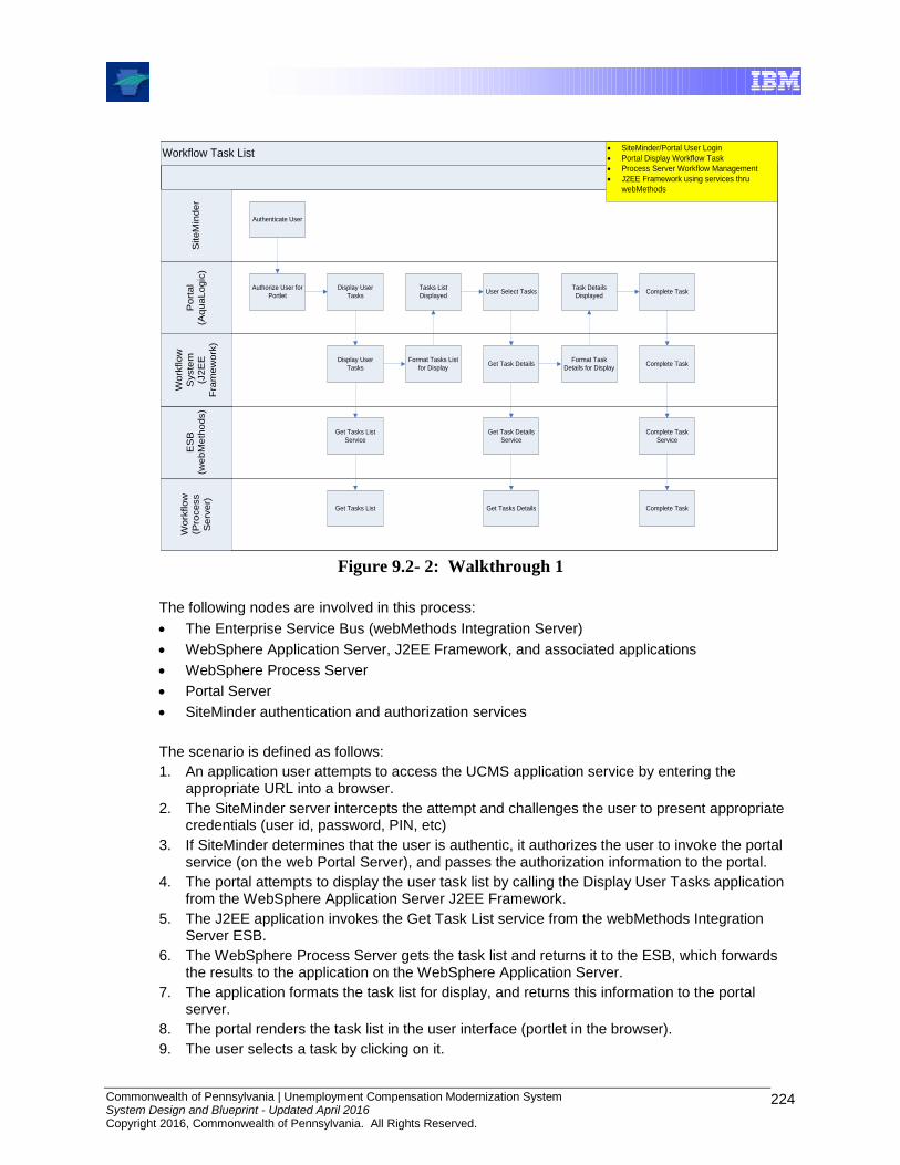
Commonwealth of Pennsylvania | Unemployment Compensation Modernization System System Design and Blueprint - Updated April 2016 Copyright 2016, Commonwealth of Pennsylvania. All Rights Reserved.
224
Workflow Task List
Site
Min
de
r
Wo
rkflo
w
(Pro
ce
ss
Se
rve
r)
ES
B
(we
bM
eth
od
s)
Wo
rkflo
w
Syste
m
(J2
EE
Fra
me
wo
rk)
Po
rta
l
(Aq
ua
Lo
gic
)
Display User
Tasks
Display User
Tasks
Get Tasks List
Service
Get Tasks List
Format Tasks List
for Display
User Select Tasks
Get Task Details
Tasks List
Displayed
Get Task Details
Service
Get Tasks Details
Format Task
Details for Display
Task Details
DisplayedComplete Task
Complete Task
Complete Task
Service
Complete Task
SiteMinder/Portal User Login
Portal Display Workflow Task
Process Server Workflow Management
J2EE Framework using services thru
webMethods
Authorize User for
Portlet
Authenticate User
Figure 9.2- 2: Walkthrough 1
The following nodes are involved in this process:
The Enterprise Service Bus (webMethods Integration Server)
WebSphere Application Server, J2EE Framework, and associated applications
WebSphere Process Server
Portal Server
SiteMinder authentication and authorization services
The scenario is defined as follows:
1. An application user attempts to access the UCMS application service by entering the appropriate URL into a browser.
2. The SiteMinder server intercepts the attempt and challenges the user to present appropriate credentials (user id, password, PIN, etc)
3. If SiteMinder determines that the user is authentic, it authorizes the user to invoke the portal service (on the web Portal Server), and passes the authorization information to the portal.
4. The portal attempts to display the user task list by calling the Display User Tasks application from the WebSphere Application Server J2EE Framework.
5. The J2EE application invokes the Get Task List service from the webMethods Integration Server ESB.
6. The WebSphere Process Server gets the task list and returns it to the ESB, which forwards the results to the application on the WebSphere Application Server.
7. The application formats the task list for display, and returns this information to the portal server.
8. The portal renders the task list in the user interface (portlet in the browser).
9. The user selects a task by clicking on it.
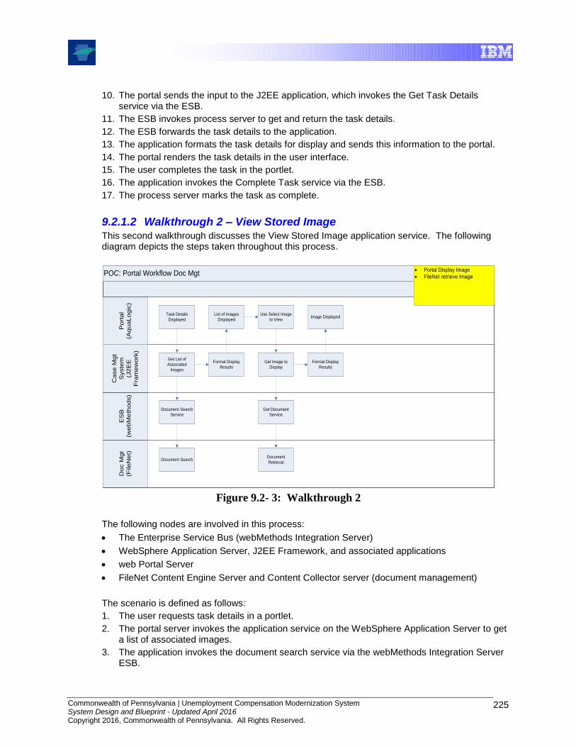
Commonwealth of Pennsylvania | Unemployment Compensation Modernization System System Design and Blueprint - Updated April 2016 Copyright 2016, Commonwealth of Pennsylvania. All Rights Reserved.
225
10. The portal sends the input to the J2EE application, which invokes the Get Task Details service via the ESB.
11. The ESB invokes process server to get and return the task details.
12. The ESB forwards the task details to the application.
13. The application formats the task details for display and sends this information to the portal.
14. The portal renders the task details in the user interface.
15. The user completes the task in the portlet.
16. The application invokes the Complete Task service via the ESB.
17. The process server marks the task as complete.
9.2.1.2 Walkthrough 2 – View Stored Image This second walkthrough discusses the View Stored Image application service. The following diagram depicts the steps taken throughout this process.
POC: Portal Workflow Doc Mgt
Do
c M
gt
(File
Ne
t)
ES
B
(we
bM
eth
od
s)
Ca
se
Mg
t
Syste
m
(J2
EE
Fra
me
wo
rk)
Po
rta
l
(Aq
ua
Lo
gic
)
Task Details
Displayed
Get List of
Associated
Images
Document Search
Service
Document Search
Format Display
Results
List of Images
Displayed
Portal Display Image
FileNet retrieve Image
Use Select Image
to View
Get Image to
Display
Get Document
Service
Document
Retrieval
Format Display
Results
Image Displayed
Figure 9.2- 3: Walkthrough 2
The following nodes are involved in this process:
The Enterprise Service Bus (webMethods Integration Server)
WebSphere Application Server, J2EE Framework, and associated applications
web Portal Server
FileNet Content Engine Server and Content Collector server (document management)
The scenario is defined as follows:
1. The user requests task details in a portlet.
2. The portal server invokes the application service on the WebSphere Application Server to get a list of associated images.
3. The application invokes the document search service via the webMethods Integration Server ESB.
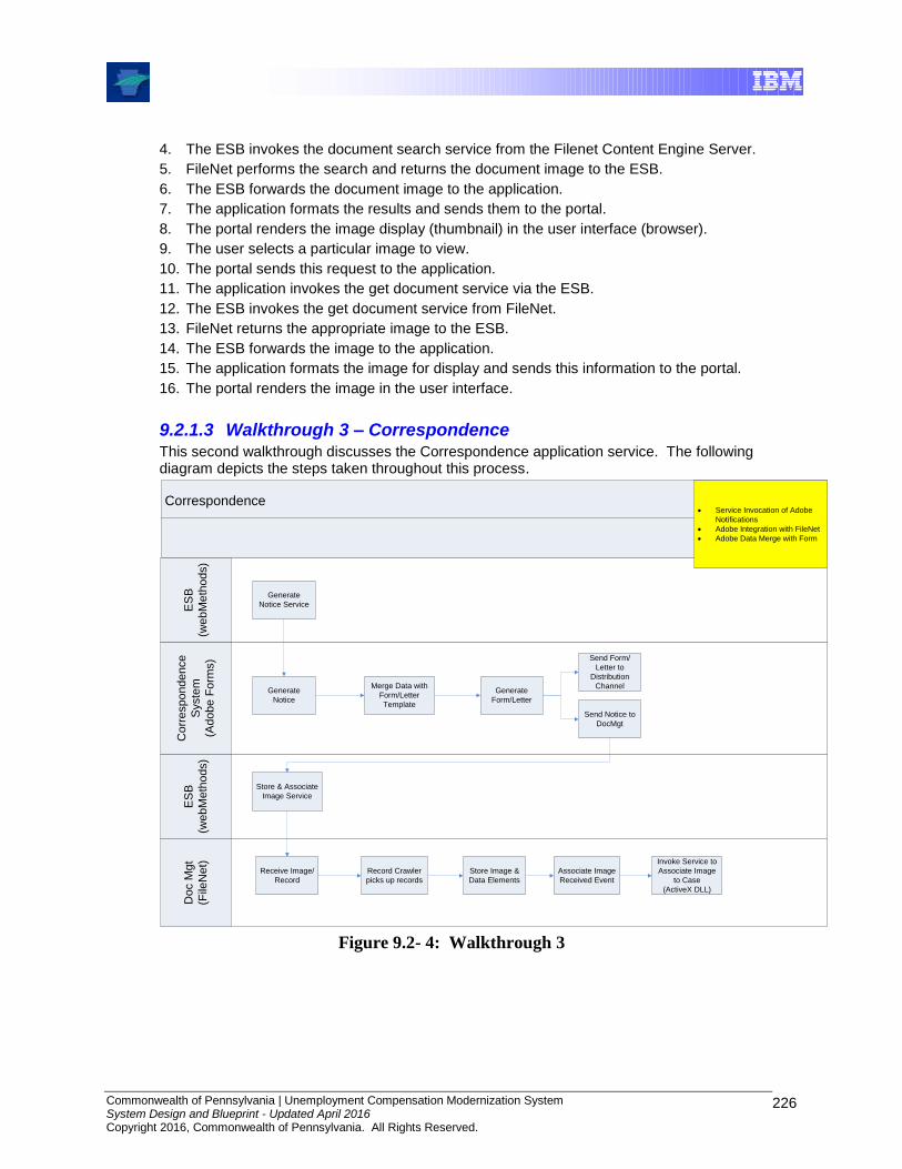
Commonwealth of Pennsylvania | Unemployment Compensation Modernization System System Design and Blueprint - Updated April 2016 Copyright 2016, Commonwealth of Pennsylvania. All Rights Reserved.
226
4. The ESB invokes the document search service from the Filenet Content Engine Server.
5. FileNet performs the search and returns the document image to the ESB.
6. The ESB forwards the document image to the application.
7. The application formats the results and sends them to the portal.
8. The portal renders the image display (thumbnail) in the user interface (browser).
9. The user selects a particular image to view.
10. The portal sends this request to the application.
11. The application invokes the get document service via the ESB.
12. The ESB invokes the get document service from FileNet.
13. FileNet returns the appropriate image to the ESB.
14. The ESB forwards the image to the application.
15. The application formats the image for display and sends this information to the portal.
16. The portal renders the image in the user interface.
9.2.1.3 Walkthrough 3 – Correspondence This second walkthrough discusses the Correspondence application service. The following diagram depicts the steps taken throughout this process.
Correspondence
Generate
Notice
Merge Data with
Form/Letter
Template
Generate
Form/Letter
Send Form/
Letter to
Distribution
Channel
Send Notice to
DocMgt
Store & Associate
Image Service
Receive Image/
Record
Record Crawler
picks up records
Store Image &
Data Elements
Associate Image
Received Event
Invoke Service to
Associate Image
to Case
(ActiveX DLL)
Co
rre
sp
on
de
nce
Syste
m
(Ad
ob
e F
orm
s)
ES
B
(we
bM
eth
od
s)
Do
c M
gt
(File
Ne
t)
ES
B
(we
bM
eth
od
s)
Generate
Notice Service
Service Invocation of Adobe
Notifications
Adobe Integration with FileNet
Adobe Data Merge with Form
Figure 9.2- 4: Walkthrough 3

Commonwealth of Pennsylvania | Unemployment Compensation Modernization System System Design and Blueprint - Updated April 2016 Copyright 2016, Commonwealth of Pennsylvania. All Rights Reserved.
227
The following nodes are involved in this process:
The Enterprise Service Bus (webMethods)
Adobe LiveCycle Forms (A WebSphere Application) correspondence system
FileNet Content Engine Server and Content Collector server (document management)
The scenario is defined as follows:
1. The webMethods Integration Server ESB invokes the generate notice service on the Adobe LiveCycle server.
2. The Adobe components complete the notice generation process by merging dynamic data (content) with stored forms or templates to generate a completed form or letter.
3. The notice generation is complete when Adobe sends the completed form to the distribution channel, and a copy to document management, which it invokes via the ESB.
4. The ESB invokes the FileNet Content Engine server store and associate image service.
5. FileNet completes the document storage and association by receiving the document from the ESB using the Content Collector server; storing the image and metadata, and invoking the Associate Image to Case service.
9.2.2 System Support Walkthroughs
This section illustrates a typical support incident using the Tivoli system management components. The following diagram illustrates these components:
Tivoli Enterprise
Portal
Tivoli Enterprise
Console GUI
Tivoli Netview
Console
UCMS Project
Help Desk
Alert
Transaction
PerformanceWebSphere
System
$UNetview
IBM Tivoli Monitoring Agents
Tivoli Data
Warehouse
Tivoli Enterprise
Console Server
Historical Analysis
Reporting
OS AIX &
Windows
Remedy
Problem
Ticket
Oracle
DB
Tivoli Enterprise
Portal
Tivoli Enterprise
Console GUI
Tivoli Netview
Console
UCMS Project
Help Desk
Alert
Transaction
PerformanceWebSphere
System
$UNetview
IBM Tivoli Monitoring Agents
Tivoli Data
Warehouse
Tivoli Enterprise
Console Server
Historical Analysis
Reporting
Historical Analysis
Reporting
OS AIX &
Windows
Remedy
Problem
Ticket
Oracle
DB
Figure 9.2- 5: System Support Walkthroughs
Commonwealth of Pennsylvania | Unemployment Compensation Modernization System System Design and Blueprint - Updated April 2016 Copyright 2016, Commonwealth of Pennsylvania. All Rights Reserved.
228
9.2.2.1 Typical component failure walkthrough In this section we document the process involved when a component experiences a failure. For this example, the Oracle database is shown as the failed component.
1. The Oracle database experiences a failure which causes application unavailability.
2. The Tivoli monitoring agent on the Oracle server will immediately send an alert to the Tivoli Enterprise Console (TEC) server that the Oracle component has filed.
3. TEC will display a high priority alert on the Enterprise Console GUI and Enterprise Portal.
4. TEC will send an e-mail to notify the UCMS project help desk that a failure has occurred, and will automatically open a problem ticket in the ServiceNow system.
5. When the problem is resolved, the Tivoli monitoring agent on the Oracle server will send an alert to TEC that the system is functioning normally.
6. TEC will update the Enterprise Console GUI and Enterprise Portal to reflect that the system has returned to normal operations.
7. The help desk support staff will enter resolution information into the ServiceNow ticket and mark it closed.