system design of dome plug - skb · system design of dome plug ... erection of a worker protection...
TRANSCRIPT

Svensk Kärnbränslehantering ABSwedish Nuclear Fueland Waste Management Co
Box 250, SE-101 24 Stockholm Phone +46 8 459 84 00
R-14-24
System design of Dome PlugExperiences from full-scale wire sawing of a slot abutment for the KBS-3V deposition tunnel plug
Pär Grahm, Svensk Kärnbränslehantering AB
Rickard Karlzén, Uppländska Bergborrnings AB
March 2015
Tänd ett lager: P, R eller TR.
System design of Dome PlugExperiences from full-scale wire sawing of a slot abutment for the KBS-3V deposition tunnel plug
Pär Grahm, Svensk Kärnbränslehantering AB
Rickard Karlzén, Uppländska Bergborrnings AB
ISSN 1402-3091SKB R-14-24ID 1446032
March 2015
Keywords: Dome plug, Deposition tunnel, Wire sawing, Slot excavation, Laser scanning, KBP1004.
A pdf version of this document can be downloaded from www.skb.se.
© 2015 Svensk Kärnbränslehantering AB

SKB R-14-24 3
Summary
A full-scale trial of the KBS-3V deposition tunnel end plug – a so called Dome Plug – was installed at the Äspö Hard Rock Laboratory during 2012–2013. The test site is located 450 metres below surface in the crystalline rock, in a purpose-built test tunnel (TAS01) which represents a short (14 metre) copy of a deposition tunnel for spent nuclear fuel (H = 4.8 m, W = 4.2 m).
The principal role of the deposition tunnel plug is to confine the backfill in place during repository operations; This is achieved through use of a strong arch-shaped concrete dome plug which transfers the loads to the rock. The concrete structure must thus be keyed into the host rock and this is done by a circumferential slot excavation. To meet up the applied requirements on geometric accuracy and need for smooth surfaces in order to reach good interaction between the cast concrete dome and the supporting rock, the slot excavation was performed by the use of a wire sawing method. The slot for casing of the concrete dome was designed as a symmetrical octagon (V-shape) and consequently 16 cuts with the wire were needed, i.e. eight cuts from each side. The resulting diameter of the excavated slot became about 8.8 metres between the deepest points of intersection.
This report summarises implementation and practical experiences of the performed wire sawing of the slot for the full-scale plug system test (DOMPLU). Based on experience from pre-study tests, the proposed wire sawing strategy for DOMPLU included four steps; i) an initial drilling campaign of all the necessary boreholes, ii) erection of a worker protection scaffold including steel mesh for the roof and walls, iii) wire sawing campaign including 16 cuts, and finally iv) blasting of the free-sawn rock segments simultaneously with blasting of the scaffolding’s bearing structure. The used method had some challenges, mainly related to rock creep. This occurrence contributed to that the wire got stuck during execution of the first pulling cuts. Because of this, the original plan was re-evaluated and method changes were introduced for the continued execution. Subsequently, only pushing cuts (blind-cuts) were used, which worked better for this purpose.
From workers safety point of view, it was imperative that the utmost consideration was given to the risk of falling stones from roof and walls. By erecting a safety scaffold and a steel net structure, below which sawing operations could be carried out, these risks could be eliminated in a successful way.
Following wire sawing and blasting, the 16 cut surfaces of the excavated slot were laser scanned to determine accurateness of the method. As expected, the wire sawing had accomplished very smooth surfaces of the slot. However, the measurements show that the wire has cut quite deep outside the theoretical cut-line at the inner central part of many surfaces. The evaluation shows that the surfaces that were cut subsequent to a cut being made from the opposite side were in general performed with much better accuracy. It can be assumed that rock stresses have contributed greatly to the outcome. After blasting and removal of muck, a small cavity was discovered in the intersection part of the slot near the tunnel roof.
The originally planned schedule for drilling, wire sawing and excavation of the octagonal slot was suggested to 42 days. The effective work was though performed in 50 days, using a single shift. The total duration of the performance was 101 days. Down-time for the contractor has been registered to a total of 17 days. The majority of this is due to positioning of boreholes by geodetic survey, scaffolding for staff, erections of platforms for drilling machines and workers safety precautions.
Overall, it was found that wire sawing is a possible method to use for slot excavations for dome plugs in the Spent Fuel Repository. The results from the full-scale test have been evaluated as toler-able and the method has potential to be further refined and tested for this purpose.
4 SKB R-14-24
Sammanfattning
Ett fullskaleförsök av deponeringstunnelpluggen i KBS-3V – en så kallad valvplugg – installerades vid Äspö laboratoriet under 2012–2013. Provplatsen är belägen 450 meter ner i det kristallina urberget, i en specialbyggd experimenttunnel (TAS01) som motsvarar en kort (14 meter) kopia av en depone-ringstunnel för använt kärnbränsle (H = 4,8 m, W = 4,2 m).
Den huvudsakliga uppgiften för deponeringstunnelpluggen är att hålla återfyllningen på plats under förvarets driftfas; Detta uppnås genom installation av en stark betongkupol som fungerar med last-överföring genom valvverkan. Betongkonstruktionen måste följaktligen kilas in i berget och detta åstadkoms genom att berget tas ut i en runtomgående slits. För att möta upp de funktionella kraven på geometrisk noggrannhet och behovet av släta bergytor för att skapa bra interaktion mellan den gjutna betongkupolen och bergfundamentet, utfördes berguttaget för slitsen med hjälp av en vajer-sågningsmetod. Slitsen som omger betongkupolen utformades som en symmetrisk oktogon (V-form) och därmed behövdes 16 sågsnitt för vajern, dvs åtta snitt från varje sida. Den resulterande diame-tern för slitsen blev cirka 8,8 meter mellan de djupaste skärningspunkterna.
Denna rapport sammanfattar genomförandet och praktiska erfarenheter av den utförda vajersågningen av slitsen till betongkupolen för det fullskaliga testet av pluggsystemet (DOMPLU). Baserat på erfa-renheter från förstudietester så inkluderade den föreslagna vajersågningsstrategin för DOMPLU fyra steg; i) en inledande borrkampanj för alla nödvändiga borrhål, ii) uppförande av en arbetarskydds-ställning inkluderat stålnät för tak och väggar, iii) vajersågningskampanj med 16 snitt, och slutligen iv) sprängning av de frisågade bergsegmenten momentant med den bärande strukturen till skydds-ställningen. Den använda metoden hade vissa utmaningar, främst relaterade till bergets egen krypning. Denna omständighet bidrog till att vajern fastnade under utförandet av de första dragande snitten. På grund av detta så omvärderades den ursprungliga planen och förändringar av metoden infördes. Under det fortsatta arbetet användes därför bara tryckande snitt vilket fungerade bättre för ändamålet.
Ur arbetarskyddssynpunkt var det absolut nödvändigt att ta ytterlig hänsyn till risken för fallande stenar från tak och väggar. Dessa risker kunde elimineras på ett framgångsrikt sätt genom att ett säkerhetsstämp och en stålnätstruktur uppfördes, under vilket sågarbetet kunde bedrivas.
Efter genomförd vajersågning och sprängning, laserskannades de 16 sågade slitsytorna för att fast-ställa utförandets precision. Vajersågningen hade som förväntat resulterat i mycket släta slitsytor. Men mätningarna visar också att vajern har skurit ganska djupt utanför den teoretiska såglinjen i den mittre inre delen av flera ytor. Utvärderingen visar att de ytor som sågades efter att ett snitt först blivit gjort från motstående sida i allmänhet utfördes med mycket bättre precision. Det kan antas att bergspän-ningar har varit starkt bidragande till att påverka utgången. Efter att berget hade rensats undan efter sprängningen så upptäcktes ett litet hålrum i slitsens skärningspunkt nära tunneltaket.
Den ursprungligt planerade tidplanen för borrning, vajersågning och uttag av den åttkantiga slit-sen föreslogs till 42 dagar. Det effektiva arbetet utfördes under 50 dagar, med bara ett arbetslag. Hela utförandet varade 101 dagar. Stillestånd för entreprenören registrerades till totalt 17 dagar. Majoriteten av detta beror på positionering av borrhål genom geodetiska inmätningar, byggnads-ställningar för personal, plattformsbyggen för borrmaskiner och arbetsmiljöåtgärder så som skrotning.
Sammantaget har det visat sig att vajersågning är en potentiell metod att använda för framtida slits-uttag för valvpluggarna i Kärnbränsleförvaret. Resultaten från fullskaletestet har utvärderats som tolerabelt och metoden har potential att ytterligare förfinas och testas för detta ändamål.
SKB R-14-24 5
Contents
1 Introduction 71.1 Background to the dome plug design 71.2 Prerequisites for the slot excavation 8
2 Planning 92.1 Desk study and feasibility testing of wire sawing 92.2 Planning of the full-scale slot excavation 10
2.2.1 Plug location and rock conditions 102.2.2 General planning 122.2.3 Drilling 132.2.4 Safety scaffold 142.2.5 Wiresawing 15
2.3 Organization and responsibilities 15
3 Performance 173.1 Core drilling of the 46 mm holes 173.2 Core drilling of the 250 mm holes 173.3 Drilling of hole for blasting of the stone segments 193.4 Safety scaffolding 193.5 Wire sawing 203.6 Reaming of 46 mm boreholes to 250 mm 233.7 Improved wire sawing procedure 243.8 Blasting of free-sawn rock segments 25
4 Results 314.1 Laser scanning 314.2 Evaluation of performed cuts 324.3 Time follow up 33
5 Discussion on future activities 35
References 37
Appendix 1 G1–G2 section 0/011 m 39
Appendix 2 G1–G2 section 0/014 m 41
Appendix 3 G1–B2 section 0/011 m 43
Appendix 4 G1–B2 section 0/014 m 45
Appendix 5 A1–G2 section 0/011 m 47
Appendix 6 A1–G2 section 0/014 m 49
Appendix 7 A2–A1 section 0/011 m 51
Appendix 8 A2–A1 section 0/014 m 53
Appendix 9 B1–B2 section 0/011 m 55
Appendix 10 B1–B2 section 0/014 m 57
Appendix 11 H1–A2 section 0/011 m 59
Appendix 12 H1–A2 section 0/014 m 61
Appendix 13 I1–B1 section 0/011 m 63
Appendix 14 I1–B1 section 0/014 m 65
Appendix 15 H1–I1 section 0/011 m 67
Appendix 16 H1–I1 section 0/014 m 69
SKB R-14-24 7
1 Introduction
The conceptual design of the KBS-3V deposition tunnel end plug is being tested in full-scale at Äspö Hard Rock Laboratory during 2012–2016, in the so-called dome plug system test (DOMPLU). The DOMPLU test represents a detailed iteration of the reference conceptual design of the plug system, as described in Section 1.1 below. In addition, the test includes implementation of possible new technology for rock excavation and installations with respect to feasibility, safety and production rate.
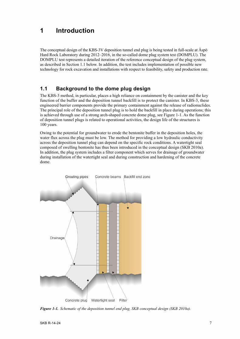
1.1 Background to the dome plug designThe KBS-3 method, in particular, places a high reliance on containment by the canister and the key function of the buffer and the deposition tunnel backfill is to protect the canister. In KBS-3, these engineered barrier components provide the primary containment against the release of radionuclides. The principal role of the deposition tunnel plug is to hold the backfill in place during operations; this is achieved through use of a strong arch-shaped concrete dome plug, see Figure 1-1. As the function of deposition tunnel plugs is related to operational activities, the design life of the structures is 100 years.
Owing to the potential for groundwater to erode the bentonite buffer in the deposition holes, the water flux across the plug must be low. The method for providing a low hydraulic conductivity across the deposition tunnel plug can depend on the specific rock conditions. A watertight seal composed of swelling bentonite has thus been introduced in the conceptual design (SKB 2010a). In addition, the plug system includes a filter component which serves for drainage of groundwater during installation of the watertight seal and during construction and hardening of the concrete dome.
Figure 1-1. Schematic of the deposition tunnel end plug, SKB conceptual design (SKB 2010a).

8 SKB R-14-24
1.2 Prerequisites for the slot excavationIn crystalline rocks there is a potential for both the host rock and the excavation damaged zone (EDZ) to provide groundwater flow paths that could short-circuit the plug. Therefore, the plugs must be keyed into the host rock, a so-called slot excavation (see Figure 1-2), and criteria to determine the suitability of the plug location must be established in advance of the decision on plug position.
The strength and properties of the rock in the area of the slot for the concrete dome have to be suitable for construction and for performance of the plug during the repository operation period. This means that long fractures should not be present at the plug location in order to prevent leakage of water past the plug. In addition, the rock surfaces for casing of the concrete dome should be so far as possible free from EDZ and smooth. A smooth surface is preferred in order for the concrete dome to release from the rock during its early shrinkage and during the controlled cooling procedure. Release of the concrete dome helps to prevent high initial tensile stresses during autogenous shrinking of the con-crete and supports successful grouting of the interface between the dome and the rock. To meet all these requirements, the wire sawing method has been proposed to be further tested and used for the DOMPLU full scale test slot excavation. In addition, for the Spent Fuel Repository at least 200 plugs will be required which means that there is also desire for efficient logistics and production rates. The pace of deposition of canisters with spent fuel in up to 300 meter long deposition tunnels involves about five plugs to be installed every year. Before deposition begins, the tunnels will be kept open during several years for various preparations. Accordingly this period allows for the slot excavation to be performed with sufficient quality and with a production rate adapted to the actual needs.
Figure 1-2. End part of a conceptual KBS-3V deposition tunnel with defined components of the plug system (vertical section).
Backfill
Filter
Bentonite seal
Concrete Dome
Slot excava�on

SKB R-14-24 9
2 Planning
In this chapter, planning of the wire sawing test for DOMPLU is described together with general descriptions of the test site and organization of work.
A wire saw is a machine using a metal wire or cable for cutting. Mining industries commonly use wire saw to cut hard stone into large blocks that can then be shipped to processing plants to be fur-ther refined. These wire saws are large machines that use diamond-impregnated segments on a cable. The saw allow the bottom of a quarry slab to be cut free (after the cable is passed through access drill holes); with the bottom cut, back and side charges (explosives) can cleanly cleave the slab. For construction purposes, wire sawing is commonly used for infrastructural excavations, either in narrow spaces or where gentle excavation is needed combined with high production rate. Based on these same principles, the commonly used wire sawing method was further developed and tested for the purpose of an octagonal slot excavation in deep geological conditions.
2.1 Desk study and feasibility testing of wire sawingBeginning with a desk study, different possible methods for the slot excavation of DOMPLU were compared and their potentials evaluated. The study suggested that wire sawing is a candidate method with respect to qualification, production rate and cost. Consequently, a decision was made to further test the wire sawing method for feasibility before conducting the definite full-scale excavation of the DOMPLU slot.
To facilitate excavation by wire sawing, the slot had been designed as an octagon, see Figure 2-1, with a symmetric borehole pattern and with established borehole angles.
The feasibility test was performed at Äspö Hard Rock Laboratory (level –460 m) during summer 2011 and included excavation of a quarter (two segments) of the full-scale slot, see Figure 2-1 below.
Figure 2-1. Schematic view of the wire sawing feasibility test set-up. Explanation: The blue fields correspond to the excavated area which was two eighths of the symmetrical octagon. Green lines are 56 mm boreholes used to test pulling cuts while yellow (outer) and red (centre) lines are 250 mm boreholes used to insert towers with a pulley wheel to test pushing cuts (i.e. blind cuts).

10 SKB R-14-24
The practical implementation of the feasibility test was prepared as two separate activities where one included the planned executions of drilling and sawing and the other defined the method for evaluation of the results by geodetic measurements and laser scanning.
During the feasibility test different ways of drilling and sawing were tested which is indicated by Figure 2-1.
Uppländska bergborrnings AB was contracted to perform the wire sawing tests and a subcontractor was used for the drilling campaign.
The most important experience from the performed core drilling was that 250 mm holes as well as the 56 mm small-diameter holes could be performed within acceptable deviations. The bore logging showed that moving and installing the machine in new positions accounted for about 60% of the total time used. If a similar machine is to be used for a full-scale excavation another type of platform should be arranged to make handling of the machine easier and quicker, especially for fine-tuning the orientation. All holes, including those for final blasting of the free-sawn segments, should be completed before sawing starts.
Main experience from the wire sawing feasibility test was that both “pushing” and “pulling” cuts with the wire were well applicable for the slot excavation, i.e. a “blind cut” pushes the wire into the rock from one side and it can thereafter be pulled out from the opposite side of the slot (see Figure 2-1).
Based on experience from the feasibility test, the following procedure was recommended to be used in the full-scale sawing for DOMPLU;
• Firstly, towers and wire should be placed in two of the 250 mm holes.
• Beginning in the lower part of the slot, sawing in-between the holes should be made by pushing an 11.4 mm wire down (blind cut) until the mid point of the wire reaches the theoretical inter-section line of the slot.
• The wire should then be replaced by one with 8 mm diameter for minimizing the risk of getting it stuck by rock movements.
• After installing extra pulleys inside the tunnel, beyond the slot, the 8 mm wire will be pulled out to the other side through the small-diameter holes.
• Lastly, the free-sawn rock segments can be successfully disintegrated by blasting and thereafter all remaining muck is to be transported out of the area. To break loose the free-sawn segments by hydraulic splitting was also tested for feasibility but that method was not considered to be as effective as using careful blasting.
The following additional issues had to be addressed before conducting a full-scale test;
• The work shifts must be planned so that no wire is left in the slot since there is always a risk for a trapped wire due to rock creep. For the same reason, pushing and pulling cuts should be made complete in one and the same work shift.
• Workers safety aspects must be further developed and approved before the full-scale test.
2.2 Planning of the full-scale slot excavationAs discussed above, the results and lessons learned from the feasibility field test were used as a plan-ning basis for the excavation strategy in full scale for DOMPLU. Below, the prerequisites for the test site are first described followed by a review of the planned slot excavation procedure by wire sawing.
2.2.1 Plug location and rock conditionsThe DOMPLU test site at Äspö HRL is located 450 metres below surface in the crystalline rock, in a purpose-built test tunnel (TAS01) which is a short (14 metre) copy of a deposition tunnel for the Spent Fuel Repository. The theoretical contour of the horseshoe-shaped tunnel is H = 4.8 m, W = 4.2 m.

SKB R-14-24 11
The set of key requirements on location of the slot excavation included:
1. A need to find an area with no continuous cracks longer than the tunnel diameter. (There was a preference for an absence of such fractures for the entire length of the experiment tunnel).
2. Visible cracks longer than 1.0 m was to be avoided and in particular, no water-bearing fractures were allowed.
3. Any fractures with an angle of incidence less than 30° against the tunnel axis were to be avoided. Such cracks can cause stability failure and split wedges from the slot.
The reasons for these requirements are to obtain the desired boundary conditions for DOMPLU and mitigate potential risks to a successful completion of the project.
As discussed in Section 1.2 the suitability of the location must be established in advance of the deci-sion on plug position. This step was thoroughly planned and evaluated before excavation of the test tunnel TAS01 started.
To prepare the tunnel excavation and decide on plug location, a 30 m pilot hole (named KJ0068A01) was drilled for the purposes of core and borehole mapping and conduct of high-pressure water injection tests (up to 10 MPa). Figure 2-2 shows a photo of the core box containing one third (the first 10 metres) of the borehole.
According to the mapping of the 30 m long borehole KJ0068A01, the most suitable geological section for DOMPLU construction is between approximately 7–11 m depth from the original tunnel face. This region corresponds to the three lowest core-sections shown in Figure 2-2. This rock section is a medium-grained, massive, fresh and almost fracture-free Ävrö granodiorite (rock code 501056). Only one open (broken) fracture was observed at position 8.7 m of the core (left-side of second core segment from bottom in Figure 2-2).
Stepwise hydraulic injection tests in the pilot borehole were performed by Geosigma. Equipment that was specifically developed for the purpose of very-high-pressure water injection of up to 10 MPa was used. The results indicated transmissivity values below the measurement limit of 2E10–13 m2/s, which corresponds to an intact rock.
Figure 2-2. Photo of the core box for pilot hole KJ0068A01, section 0–10 m (wet core).

12 SKB R-14-24
Based on the examined hydrogeological conditions, a decision was made to place the slot for the concrete dome between 7.2 m (downstream) and 10.4 m (upstream) from the original tunnel face. Since the total length of DOMPLU – including bentonite seal, filter section and backfill – was designed as a 6.5 m long installation and the length of the slot excavation is approximately 3.2 m, the total tunnel length that needed to be excavated for TAS01 was determined to be 13.7 metres.
The reference method for excavation of deposition tunnels is drilling and smooth-blasting tech-niques. Experience shows that when proper control of drilling and blasting procedures is applied, tunnels with acceptable excavation damaged zone (EDZ) and geometry can be constructed (SKB 2010b). For the DOMPLU experiment tunnel, it was decided to attempt to reduce further the magni-tude of the EDZ through careful blasting in a two-step excavation method. A further description of this tunnel excavation is provided by Grahm et al. (2015) while a photo of the fully extended experi-ment tunnel is shown by Figure 2-3.
2.2.2 General planningAn overall work breakdown structure for the full-scale slot excavation by wire sawing is provided by Table 2-1.
Primary data, daily logs and other results from these three work packages are registered in SKB’s database SICADA with associations to their respective activity plan (SKB internal documents).
Table 2-1. Work breakdown structure of project “KBP1004 – System design of Dome Plug” for the purpose of slot excavation in full-scale by wire sawing.
Äspö HRL Id No. (AP TD -)
Description of work
KBP1004-11-041 Core drilling, characterization and investigation program for the test tunnel TAS01.KBP1004-12-010 Full-scale test of Dome Plug – Slot excavation by wire sawing.KBP1004-12-059 Full-scale test of Dome Plug – Laser scanning of rock surfaces.
Figure 2-3. Photo of the completed test tunnel TAS01 where geodetic survey is ongoing.

SKB R-14-24 13
Based on the feasibility test, described in Section 2.1, the proposed wire sawing strategy for DOMPLU included;
• An initial drilling campaign of all the necessary boreholes, i.e. both holes for wire sawing and for the concluding blasting of free-sawn rock.
• Erection of a worker protection scaffold including steel mesh for the roof and walls,
• Establishing of wire sawing equipment on site, and sawing operation.
• When the sawing has been completed, blasting of the free-sawn rock segments is done simultane-ously with blasting of the safety scaffolding bearing structure.
Details of the work planning are described below while the actual performance is described in Chapter 3. Finally, the outcome of the full-scale test is presented in Chapter 4 followed by recom-mendations for future studies given in Chapter 5.
2.2.3 DrillingIn Figure 2-4 the planned drilling and sawing strategy is presented in a schematic manner. The detailed borehole pattern was based on construction drawings, specifying the predefined octagonal shape of the slot and the corresponding angles of each borehole.
From the upstream side of the slot (left side in Figure 2-4) eight small-diameter boreholes with a hole-diameter of 46 mm were planned. The equipment for core drilling could be precisely fitted in the narrow place between the slot and the tunnel face of TAS01 and this contributed to that boring could be planned for greater accurateness than would have been the case with a handheld drilling machine. The purpose of these eight small-diameter holes was to be able to pull the wire out through the boreholes subsequent to a blind cut from the downstream side. The feasibility testing, described by Section 2.1, showed that pulling cuts resulted in surfaces that are more planar compared to blind cutting. Furthermore, drilling of small-diameter holes is favorable compared to ∅250 mm.
From the downstream side of the slot eight core-holes with a diameter of 250 mm were drilled so they transfixed the respective 46 mm hole and continued about 800 mm deeper. This extra depth is necessary for the guide pulleys since the wire cannot form a straight line between the ends of two adjacent holes. The eight large-diameter boreholes were planned to be used for the blind cuts.
When all holes needed for the wire sawing had been completed, the holes to use for blasting were planned to be drilled with a diameter of 38 mm.
Figure 2-4. Vertical section of the slot excavation, showing the principle location of core drilled holes to be used for wire sawing. Blue lines represent small-diameter holes (46 mm) and red lines represent 250 mm holes. No.1 shows direction for the planned push-sawing (blind cuts) and No.2 shows direction for the subsequent pulling cuts.

14 SKB R-14-24
2.2.4 Safety scaffoldTo protect the workers from potentially falling rocks, it was deemed necessary to erect a steel beam structure. This safety scaffolding was specially developed for the DOMPLU test and dimensioned so it would be able to support the big rock segments cut free by the wire sawing. The mass of each segment of rock cut by the wire sawing was up to 10 000 kg. Cutouts from the construction drawings of the safety scaffolding are presented by Figure 2-5 and Figure 2-6.
Figure 2-5. Cross section of the safety scaffolding structure, seen towards the tunnel face. Cutout from construction drawing. Text in Swedish.
Figure 2-6. Axial section of the safety scaffolding structure, with the tunnel face of TAS01 to the left. Cutout from construction drawing. Text in Swedish.

SKB R-14-24 15
A special consideration in the design was to arrange the scaffolding so it would allow the wire and pulleys to work free underneath. As seen to the left in Figure 2-6 a beam structure should also be mounted on the tunnel face wall to allow for an easy fastening and repositioning of the wire pulleys.
2.2.5 WiresawingThe planned wire sawing procedure was to start with cutting loose the bottom rock segment at the tunnel floor. The first step was to insert the guide pulleys into the two adjacent 250 mm holes and perform a blind cut between them, see the red line (No.1) in Figure 2-4. After this the wire would be thread through the 46 mm holes on the opposite side of the slot, thence a pulling cut should be performed, according to the blue line (No.2) in Figure 2-4. This procedure would then continue by sawing the rock segments in the walls on each side. Finally, sawing would be done in the tunnel roof followed by charging and blasting of all eight segments and the safety scaffold in one sequence.
2.3 Organization and responsibilities The project field organization, including clarification of responsibilities for each task, was thoroughly described in activity plans according to Section 2.2.2.
The main contractor for the slot excavation was Uppländska Bergborrnings AB. They were contracted for coordination of hammer- and core drilling, assembly of the safety scaffolding, wire sawing and documentation of the work by daily logs.
Uppländska Bergsborrning AB used three subcontractors:
• Olstam Borrteknik AB (for the core drilling),
• Plåtson (for assembly of the safety scaffolding), and
• ZUBLIN Scandinavia AB (for the later reaming of the 46 mm core-holes to 250 mm).
Before the work could begin, the main contractor delivered a Quality plan and a Work environment plan as a basis to SKB’s detailed planning and risk assessment.
SKB’s own responsibilities were to supply with water, electricity, ventilation, lights and platforms as well as a wheel-mounted loader for lifting and transports of equipment via the tunnel ramp. SKB was also responsible for providing the geodetic surveyor assistance, scaffolding assembly (i.e. platforms for workers and drilling machines) as well as general instructions for work, including directives on work environment.
Furthermore, SKB coordinated the final blasting of the free-sawn rock segments via a separate contractor, Strabag, a company which had also excavated the test tunnel TAS01.

SKB R-14-24 17
3 Performance
This chapter describes the actual performance of the slot excavation in relation to the planning described in the previous chapter.
3.1 Core drilling of the 46 mm holesThe drilling of 46 mm holes began with drilling of the holes in the floor. Due to the uneven rock surface at the floor of the tunnel, it was necessary to build a platform for the drilling machine. This platform was then adjusted to different levels so that the holes in the walls and roof could be drilled. Whenever the platform was adjusted to a new level, the drilling machine had to be removed and it was required by SKB to use trained staff for the rebuilding of the platform. The positioning and orientation of the drill rig was done in collaboration with a geodetic assistant in order to provide good accuracy to the drilling. The placement, naming and drilling length of the 46 mm core-holes are visualized by Figure 3-1.
3.2 Core drilling of the 250 mm holesAt time for core drilling of the 250 mm holes, the original drilling machine planned for use could not be made available. To keep up with the schedule the subcontractor tried to drill these holes with the same machine that had been used for the 46 mm holes. However, this was not functional and instead it resulted in a machine breakdown. The project management decided to use the downtime for cast-ing of a concrete wall in the tunnel face of TAS01.
Figure 3-1. Principle sketch showing the placement, naming and drilling length of each 46 mm hole.

18 SKB R-14-24
The core drilling of 250 mm holes was resumed after the summer holiday in 2012 and at this time a more feasible drilling machine could be utilized. The same procedure as described in Section 3.1 was followed, with adjustable platforms and borehole positioning by geodetic survey. The placement, naming and drilling length of the 250 mm core-holes are shown in Figure 3-2.
Two photos of the machine that was successfully used for the 250 mm core drilling are provided by Figure 3-3.
Figure 3-2. Principle sketch showing the placement, naming and drilling length of each 250 mm hole.
Figure 3-3. Equipment for core drilling of the ∅250 mm holes.
SKB R-14-24 19
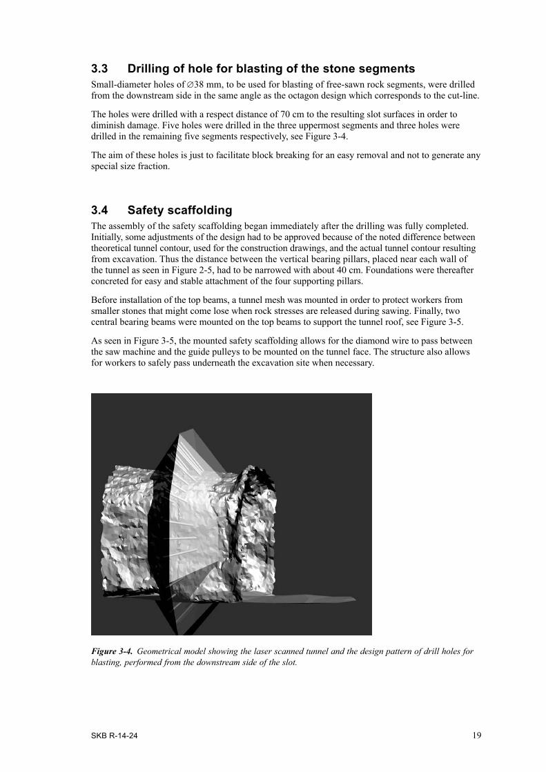
3.3 Drilling of hole for blasting of the stone segmentsSmall-diameter holes of ∅38 mm, to be used for blasting of free-sawn rock segments, were drilled from the downstream side in the same angle as the octagon design which corresponds to the cut-line.
The holes were drilled with a respect distance of 70 cm to the resulting slot surfaces in order to diminish damage. Five holes were drilled in the three uppermost segments and three holes were drilled in the remaining five segments respectively, see Figure 3-4.
The aim of these holes is just to facilitate block breaking for an easy removal and not to generate any special size fraction.
3.4 Safety scaffoldingThe assembly of the safety scaffolding began immediately after the drilling was fully completed. Initially, some adjustments of the design had to be approved because of the noted difference between theoretical tunnel contour, used for the construction drawings, and the actual tunnel contour resulting from excavation. Thus the distance between the vertical bearing pillars, placed near each wall of the tunnel as seen in Figure 2-5, had to be narrowed with about 40 cm. Foundations were thereafter concreted for easy and stable attachment of the four supporting pillars.
Before installation of the top beams, a tunnel mesh was mounted in order to protect workers from smaller stones that might come lose when rock stresses are released during sawing. Finally, two central bearing beams were mounted on the top beams to support the tunnel roof, see Figure 3-5.
As seen in Figure 3-5, the mounted safety scaffolding allows for the diamond wire to pass between the saw machine and the guide pulleys to be mounted on the tunnel face. The structure also allows for workers to safely pass underneath the excavation site when necessary.
Figure 3-4. Geometrical model showing the laser scanned tunnel and the design pattern of drill holes for blasting, performed from the downstream side of the slot.

20 SKB R-14-24
3.5 Wire sawingThe equipment used for the DOMPLU full-scale slot excavation was an electronic diamond wire saw, model VIP 915 Inverter.
The planned sawing sequence was to work from bottom and upward the sides to finally end with the roof section. Consequently, wire sawing began at the bottom segment by inserting guide pulleys into the two adjacent 250 mm holes on the downstream side of the slot, see Figure 3-6. A blind cut was then performed between them as the wire was pushed onto the rock as the wire-sawing machine moved backward on its rail, shown by Figure 3-7.
Figure 3-5. Photos from assembly of the safety scaffolding with a tunnel mesh to protect workers from falling stones.
Figure 3-6. The guide pulleys inserted in the 250 mm bottom holes together with steering wheels for the wire connected to the wire saw machine.

SKB R-14-24 21
A photo of the control panel to the wire saw machine can be seen in Figure 3-8. Apparently the control panel is located well behind and beside the excavation zone due to the risk of that a retracted wire can break and be thrown backwards.
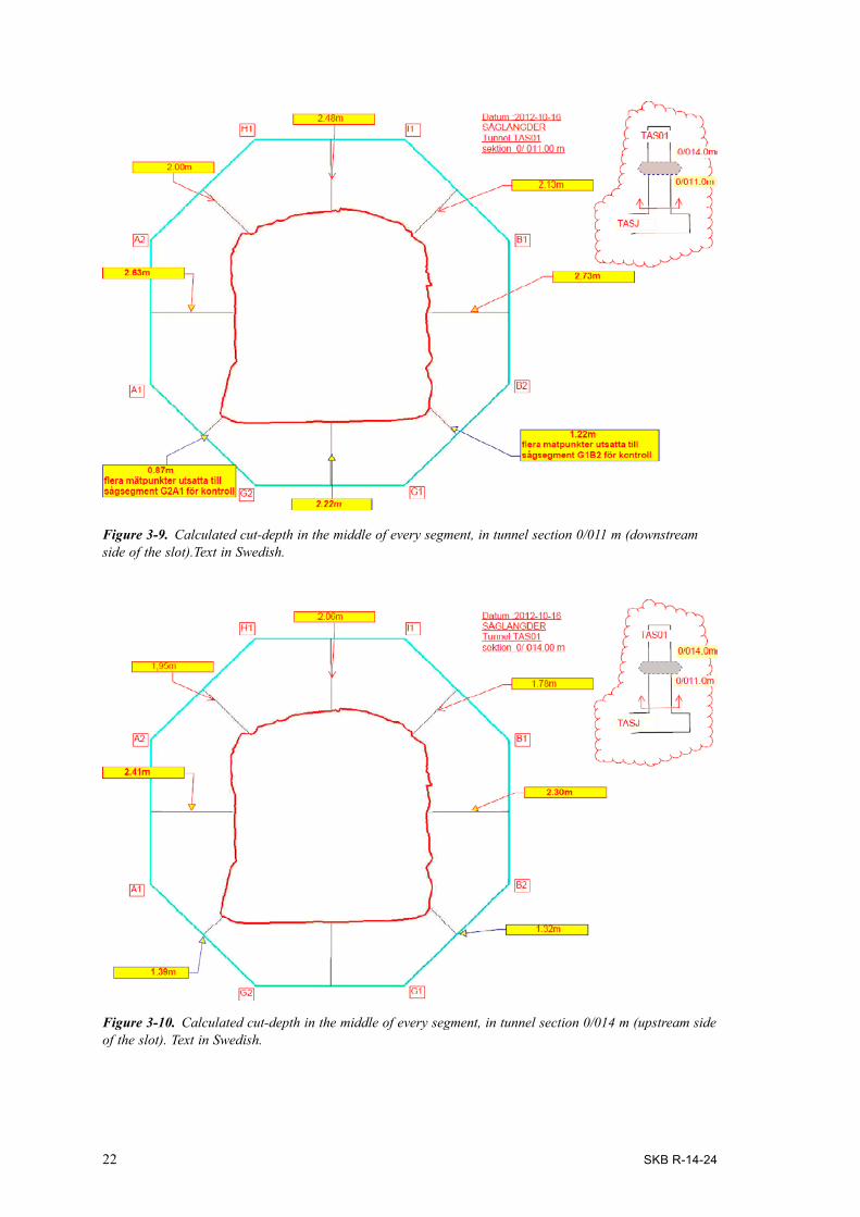
Principle drawings with the actual cut-depth had been prepared before wire sawing, see Figure 3-9 and Figure 3-10. With this basic support, the contractor could control that the required cut-depth was reached. This was done manually by yardstick measurements subsequent to stopping the wire saw.
Figure 3-7. The wire saw machine mounted on rail.
Figure 3-8. Control panel for the wire saw machine.
22 SKB R-14-24
Figure 3-9. Calculated cut-depth in the middle of every segment, in tunnel section 0/011 m (downstream side of the slot).Text in Swedish.
Figure 3-10. Calculated cut-depth in the middle of every segment, in tunnel section 0/014 m (upstream side of the slot). Text in Swedish.

SKB R-14-24 23
In the full-scale sawing for DOMPLU, it proved problematic to thread the wire through the small-diameter holes as planned. Once threading was accomplished, it was then problematic to start sawing without a wire break. A detailed description of experienced problems is given below.
When the first cut in the bottom (G1–G2, see Figure 3-9) was complete, the 11 mm wire was as planned replaced by a 8 mm wire and it was pulled through the two 46 mm holes that intersect the respective 250 mm hole (for sawing direction No.2 in Figure 2-4). Immediately after the saw machine was started, the wire jammed. A lot of effort was given to release it and to arrange a softer curve for the wire in the bottom of the hole so that the wire more easily could start running. When sawing resumed, it went very heavy and slow and it was understood that the rock had clamped the wire. When about one meter remained of the first pulling cut, the wire got fully trapped and broke. Countless efforts were again done to release the wire and thereafter change it to a thinner 6 mm wire to be able to finish the pulling cut G1–G2 towards the upstream side of the slot.
After that, the second blind cut between G2 and A1 commenced but already after 45 minutes it was observed that the open cut behind the 11,3 mm wire had been compressed with approximately 3 mm. The blind cut was however performed successfully all the way through. The sawing proceeded with the third blind cut, between G1 and B2. When this cut was finished a new attempt was done to do a pulling cut towards the upstream side of the slot. An 8 mm wire was then threaded through the 46 mm holes (for sawing direction No.2 in Figure 2-4) for the inner cut between G2 and A1. Once again the wire was trapped just from the start.
The potential of problematic rock creep-movements was recognized during pre-study tests but it was initially expected that rapid installation and start to sawing would be enough to avoid this complication. However, as described above, within just 45 minutes of installation the wire became unrecoverably stuck in the borehole.
After several attempts to achieve pulling cuts via small diameter boreholes, a revision of the proce-dure was made followed by a decision to ream all ∅46 mm to ∅250 mm. Thereafter the plan was to continue with blind cuts also being used for the upstream side of the slot, as shown by Figure 3-11 below.
The reaming of all eight small-diameter boreholes is described in Section 3.6 and the improved wire sawing procedure is further elaborated in Section 3.7.
3.6 Reaming of 46 mm boreholes to 250 mmThe reaming of eight small-diameter boreholes had to be performed by percussion drilling in two steps. First, reaming was done from ∅46 mm to ∅165 mm followed by a second reaming to ∅250 mm. The holes also had to be deepened +0.8 m to make room for the guide pulleys that must be fixed in the bottom of each hole to accomplish a blind cut. This principle is illustrated by blue lines in Figure 3-11.
Due to the limited space in the experiment tunnel a compact drill rig was used. The drill rig was a 704–1E from KLEMM Bohrtechnik. A special arrangement of the machine had to be done by rotat-ing the mast to be able to drill the holes on the upstream side (section 0/014 m). Thence drilling could be done under and above as well as in a backward direction from the drill rig.
The drilling was conducted in the following sequence; G1–G2–A1–B2–I1–H1–B1–A2, see Figure 3-10 for location of the respective borehole naming.
During reaming, problems occurred when the 165 mm drill bit crossed the already existing 250 mm borehole. The bigger radius of the existing hole made it difficult to centre the 165 mm drill bit because it tended to glide along the side of the hole. This caused further problems when the 165 mm hole was subsequently reamed to 250 mm since the 250 mm drill bit preferred to follow the 165 mm hole. Thus the end part of some boreholes got profoundly curved. This deviation actually made one drill bit stuck in the hole and a lot of efforts had to be given to make it come off. In addition, the resulting borehole deviations caused problems with not achieving enough space for the guide pulleys. Pulley wheels with a smaller diameter therefore had to be ordered to succeed with wire installation in these boreholes.

24 SKB R-14-24
3.7 Improved wire sawing procedureFigure 3-11 illustrates the improved wire sawing sequence to excavate a partial section of the octagonal slot by dragging the wire along the rock web between two neighbouring boreholes by only using blind cuts.
After reaming of boreholes (illustrated by blue lines in Figure 3-11) was accomplished, the blind cut for G1–B2 and G2–A1 on upstream section 0/014 m was first done. (Locations of G1–B2 and G2–A1 are provided by Figure 3-10). These two cuts were followed by the two blind cuts for A1–A2 and B2–B1 on upstream section 0/014 m. In the next step, blind cuts from the opposite side were made for A1–A2 and B2–B1 on downstream section 0/011 m. Subsequently the blind cuts A2–H1 and B1–I1 on upstream section 0/014 m were done, followed by the blind cuts A2–H1 and B1–I1 on downstream section 0/011 m.
When the last blind cut H1–I1 on the upstream section 0/014 m was almost completed, there were problems in measuring the depth of the cut. It was not possible to get a thin 3 mm steel band to the bottom of the cut. Instead the final sawing had to be based on acquired experience of time needed to reach a full depth. Later, when the rock had been removed, it was evident that the sawing had reached enough depth. However, it was a big deviation on the rock surface, see Chapter 4.
Lastly, the cut between H1–I1 on the downstream section 0/011 m was accomplished and thereafter the sawing machine and rails could be removed from the site.
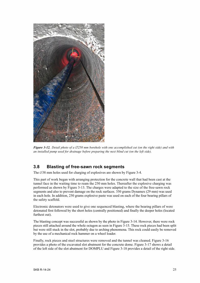
Figure 3-12 shows a detail photo of an open ∅250 mm borehole with one accomplished cut and with an installed pump used for drainage before preparing the next blind from the same hole.
Figure 3-11. a) Principle for drilling and wire-sawing of the slot by blind cuts only. b) Diameter of the boreholes for emplacement of tower and pulley for the wire.
b)
φ 250 mm φ 250 mm
a)
SKB R-14-24 25
Figure 3-12. Detail photo of a ∅250 mm borehole with one accomplished cut (on the right side) and with an installed pump used for drainage before preparing the next blind cut (on the left side).
3.8 Blasting of free-sawn rock segmentsThe ∅38 mm holes used for charging of explosives are shown by Figure 3-4.
This part of work began with arranging protection for the concrete wall that had been cast at the tunnel face in the waiting time to ream the 250 mm holes. Thereafter the explosive charging was performed as shown by Figure 3-13. The charges were adapted to the size of the free-sawn rock segments and also to prevent damage on the rock surfaces. 350 grams Dynamex (29 mm) was used in each hole. In addition, 250 grams explosive paste was used on each of the four bearing pillars of the safety scaffold.
Electronic detonators were used to give one sequenced blasting, where the bearing pillars of were detonated first followed by the short holes (centrally positioned) and finally the deeper holes (located furthest out).
The blasting concept was successful as shown by the photo in Figure 3-14. However, there were rock pieces still attached around the whole octagon as seen in Figure 3-15. These rock pieces had been split but were still stuck in the slot, probably due to arching phenomena. This rock could easily be removed by the use of a mechanical rock hammer on a wheel loader.
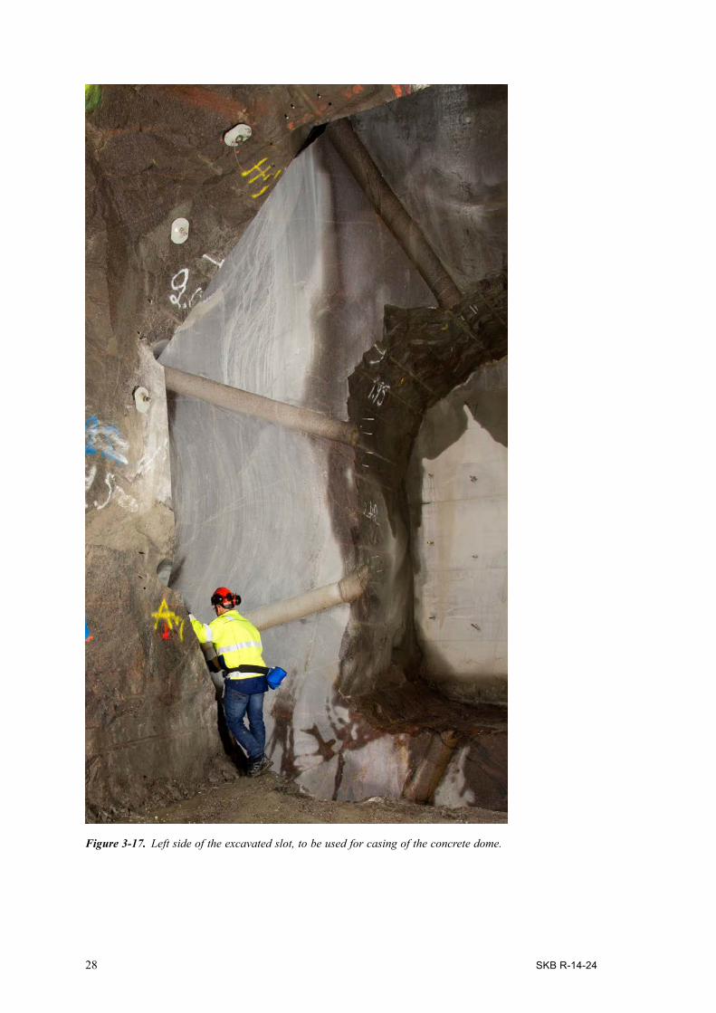
Finally, rock pieces and steel structures were removed and the tunnel was cleaned. Figure 3-16 provides a photo of the excavated slot abutment for the concrete dome. Figure 3-17 shows a detail of the left side of the slot abutment for DOMPLU and Figure 3-18 provides a detail of the right side.

26 SKB R-14-24
Figure 3-13. Explosive charging of the steel pillars and free-sawn rock segments. At the tunnel face a protection was arranged for the concrete wall.
Figure 3-14. A view of the experiment tunnel TAS01 after blasting of the safety scaffold bearing structure and the free-sawn rock segments of the DOMPLU slot abutment.

SKB R-14-24 27
Figure 3-15. Detail photo of the remaining rock in the top and sides of the slot after blasting. This rock was removed by the use of a mechanical hammer.
Figure 3-16. A view of the experiment tunnel TAS01 with the excavated slot abutment for the concrete dome.
28 SKB R-14-24
Figure 3-17. Left side of the excavated slot, to be used for casing of the concrete dome.

SKB R-14-24 29
Figure 3-18. Right side of the excavated slot, to be used for casing of the concrete dome.

SKB R-14-24 31
4 Results
In this chapter, the performed measurements of the excavated slot are described followed by an evaluation of the performed cuts.
4.1 Laser scanningSubsequent to removal of the muck and cleaning of the tunnel, the octagonal slot (with 16 surfaces) was scanned by laser measurement to be able to evaluate planarity of the sawn surfaces. There was no specific requirement on acceptable surface deviations but the ambition during the full-scale test was to saw as close to the theoretical octagon design as possible.
The measurement equipment used was a Trimble VX and the pattern was 2×2 cm. The primary data of the laser scanning was converted into a 3D-model that could be compared to the theoretical model of the octagonal slot.
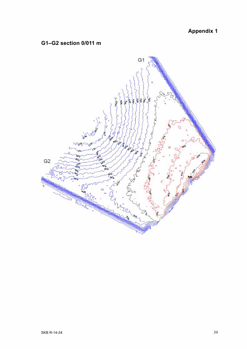
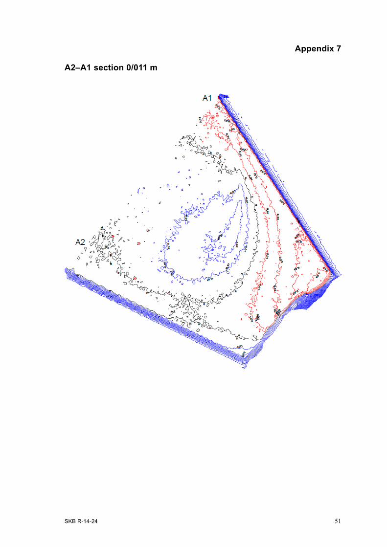
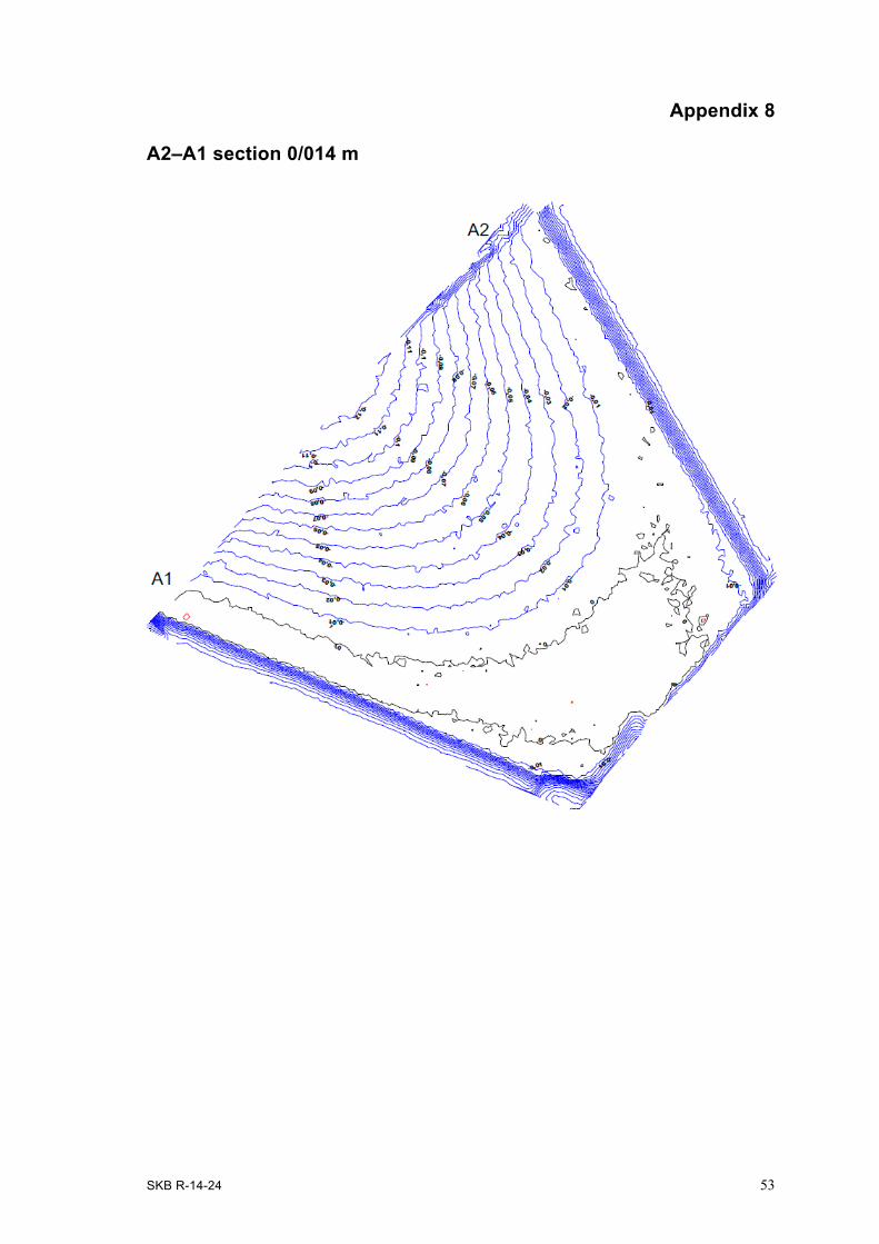
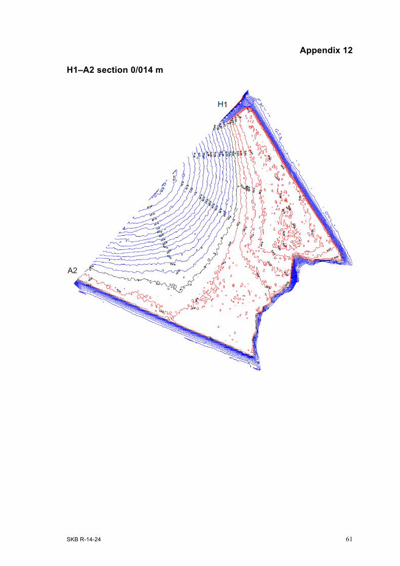
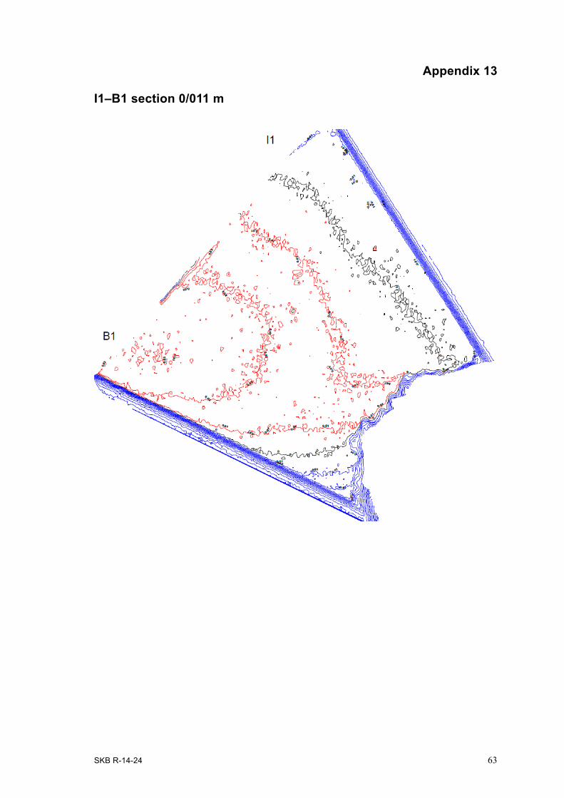
For each of the 16 measured surfaces, isolevels (1 cm) were produced on CAD-drawings, see Appendix 1–16. These drawings give a detailed view of the differences between the theoretical slot planes and the excavated surfaces. In the Appendices, black lines correspond to the theoretical plane (i.e. zero deviation) while blue lines are deeper than the theoretical plane and red lines are above the theoretical plane. In other words, a blue line marked with isolevel 0.02 is two centimetres deeper than the theoretical plane in the slot design.
The measurements show that there are variations in planarity of the surfaces. Table 4-1 compiles the biggest nonconformity range in planarity for each cut.
Table 4-1. Nonconformity range measured in the centre area of each cut.
Cut order Cut Section Nonconformity at tunnel wall (cm)
Nonconformity at intersection (cm)
Appendix
1. G1–G2 0/011 +3 –12 Appendix 12. G1–G2 0/014 –7 +1 Appendix 23. A1–G2 0/011 –6 –15 Appendix 54. G1–B2 0/011 –1 –20 Appendix 35. G1–B2 0/014 +1 +2 Appendix 46. A1–G2 0/014 +1 –1 Appendix 67. A2–A1 0/014 0 –12 Appendix 88. B1–B2 0/014 –2 –9 Appendix 109. A2–A1 0/011 +2 0 Appendix 710. B1–B2 0/011 –1 +2 Appendix 911. H1–A2 0/014 +2 –15 Appendix 1212. I1–B1 0/014 +1 –14 Appendix 1413. H1–A2 0/011 –1 –1 Appendix 1114. I1–B1 0/011 0 +2 Appendix 1315. H1–I1 0/014 –2 –29 Appendix 1616. H1–I1 0/011 0 0 Appendix 15

32 SKB R-14-24
4.2 Evaluation of performed cutsNonconformities within +3 to –3 centimetres compared to the theoretical plane were judged to be good enough not needed to be remarked in this study. In general, the measurements show that the wire has been centred with quite good precision in the boreholes in order to stay within this range when sawing begins. The two exceptions noted, nonconformities of G1–G2 (–7 cm) and A1–G2 (–6 cm) near tunnel wall, most likely have causes in the initial problems with clamped wire as described in Section 3.5.
The major nonconformities are instead found at the end of some cuts, near the intersection of the slot. A main finding from the measurement results provided by Appendix 1-16, concise in Table 4-1, is that the excavated surfaces are deeper than the theoretic plane near the intersection point for eight of the sixteen performed cuts. This is believed to be a consequence of stresses in the rock. It can be noted that when the first cut (from downstream side, 0/011) for each segment has been made, the following cut (from upstream side 0/014) was performed closer to the target cut line. This is likely an effect of released stresses in the rock as a result of the nearby cuts.
In Figure 4-1, a 3D-model composed of data from the 16 laser scanned slot surfaces has been incorporated in the laser scanned model of experiment tunnel TAS01. (Before wire sawing, the experiment tunnel TAS01 had also been laser scanned using a measurement pattern of 5×5 cm).
From structural point of view, an evaluation of the small surface nonconformities showed that there is no risk for reduced stability of the concrete dome. Calculations confirm that the octagonal shape of the slot is tolerant of small deviations. However, it would be beneficial to study possible improve-ments of the method to be able to cut closer to the theoretical model in future excavations by wire sawing.
As shown by Figure 4-2, a resulting cavity was found in the left side crest of the slot (between A2 and H1 in Appendix 11). This is not believed to be damage from blasting but to be due to a combina-tion of rock stresses and the overlapping blind cuts which probably reduced rock stability at the deepest intersection point between these two cuts.
Figure 4-1. Illustrative 3D-model structured of data from laser scanning of TAS01 and the excavated slot abutment (seen from above).

SKB R-14-24 33
4.3 Time follow upThe originally planned schedule for drilling, wire sawing and excavation of the octagonal slot was suggested to about 42 days. The performance was however completed during a total period of 101 days. As shown by Table 4-2, the effective work was carried out in 50 days, using a single shift. Besides the complication from stuck wires due to rock creep and a change of excavation strategy, the schedule for start of the work was delayed about two months from the original plans. This had the effect that the contractor had to re-plan work and double shifts could not be used due to fact that machines and personnel were at the same time busy on other construction sites. Consequently the performance of the rock excavation by wire sawing could not be as effective as originally planned and lost time could not be recaptured.
The remedial reaming of the ∅46 mm boreholes to ∅250 mm, added about eight days to the excavation schedule. Therefore, the complete excavation by wire sawing ended up requiring about 50 days of effective work by the single shift. Table 4-2 provides a specification of days of effective work needed for the different activities of the slot excavation. Note that these times do not include stand-still times required for building platforms for drilling machines and scaffolding for staff. Nor does it include the drill rig breakdown and the summer holiday period used for casting and hardening of a concrete wall at the TAS01 tunnel face.
Table 4-2. Performance time (days) for different excavation activities.
Activity Rigging Alignment Performance Comments
Core drilling ø46 mm 2 3 1,5 Core drilling ø250 mm 2 2 6,5 Reaming ø46 mm to ø250 mm 1 5 Performance includes 165 mm and 250 mmSawing 5 8 Blasting 6 8 Rock removal not included Total time (days) 16 5 29
Figure 4-2. Detail photo of the left side crest of the excavated slot where a cavity occurred.

34 SKB R-14-24
The full-scale test sawing in the short TAS01-tunnel was much more difficult than will be the case in a final repository where full length deposition tunnels (up to 300 m) are available. In a full length tunnel, saw machines can work from both sides of the slot, possibly two machines at the same time. However, in this full-scale test, sawing could be carried out from the downstream side of the slot only, limited by the short distance to the tunnel face. Consequently, special arrangements were needed for the sawing. These arrangements included extra steering wheels mounted on the tunnel face to be able to turn direction of the wire towards the boreholes located on the upstream side of the slot. This was necessary since the machine could be positioned on the downstream side of the slot only.
In addition, it is important to note that preparations and service activities on site must be attentive so that waiting times for a contractor can be reduced. The majority of down-time was due to positioning of boreholes by geodetic survey, erection of platforms for drilling machines, scaffolding and workers safety precautions. During the slot excavation by wire sawing there was also an ongoing expansion of the Äspö Hard Rock Laboratory in a close-by part of the tunnel system. As a result, there was stand-still time also related to staff evacuation of the underground area in connection to each blast-ing. This included waiting time for ventilation of the tunnel system. In total, the contractor’s waiting time was registered to 17 days.
SKB R-14-24 35
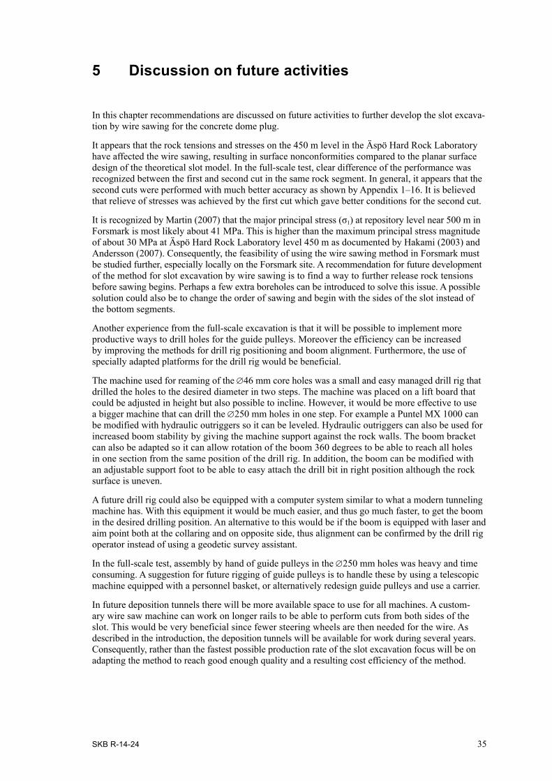
5 Discussion on future activities
In this chapter recommendations are discussed on future activities to further develop the slot excava-tion by wire sawing for the concrete dome plug.
It appears that the rock tensions and stresses on the 450 m level in the Äspö Hard Rock Laboratory have affected the wire sawing, resulting in surface nonconformities compared to the planar surface design of the theoretical slot model. In the full-scale test, clear difference of the performance was recognized between the first and second cut in the same rock segment. In general, it appears that the second cuts were performed with much better accuracy as shown by Appendix 1–16. It is believed that relieve of stresses was achieved by the first cut which gave better conditions for the second cut.
It is recognized by Martin (2007) that the major principal stress (σ1) at repository level near 500 m in Forsmark is most likely about 41 MPa. This is higher than the maximum principal stress magnitude of about 30 MPa at Äspö Hard Rock Laboratory level 450 m as documented by Hakami (2003) and Andersson (2007). Consequently, the feasibility of using the wire sawing method in Forsmark must be studied further, especially locally on the Forsmark site. A recommendation for future development of the method for slot excavation by wire sawing is to find a way to further release rock tensions before sawing begins. Perhaps a few extra boreholes can be introduced to solve this issue. A possible solution could also be to change the order of sawing and begin with the sides of the slot instead of the bottom segments.
Another experience from the full-scale excavation is that it will be possible to implement more productive ways to drill holes for the guide pulleys. Moreover the efficiency can be increased by improving the methods for drill rig positioning and boom alignment. Furthermore, the use of specially adapted platforms for the drill rig would be beneficial.
The machine used for reaming of the ∅46 mm core holes was a small and easy managed drill rig that drilled the holes to the desired diameter in two steps. The machine was placed on a lift board that could be adjusted in height but also possible to incline. However, it would be more effective to use a bigger machine that can drill the ∅250 mm holes in one step. For example a Puntel MX 1000 can be modified with hydraulic outriggers so it can be leveled. Hydraulic outriggers can also be used for increased boom stability by giving the machine support against the rock walls. The boom bracket can also be adapted so it can allow rotation of the boom 360 degrees to be able to reach all holes in one section from the same position of the drill rig. In addition, the boom can be modified with an adjustable support foot to be able to easy attach the drill bit in right position although the rock surface is uneven.
A future drill rig could also be equipped with a computer system similar to what a modern tunneling machine has. With this equipment it would be much easier, and thus go much faster, to get the boom in the desired drilling position. An alternative to this would be if the boom is equipped with laser and aim point both at the collaring and on opposite side, thus alignment can be confirmed by the drill rig operator instead of using a geodetic survey assistant.
In the full-scale test, assembly by hand of guide pulleys in the ∅250 mm holes was heavy and time consuming. A suggestion for future rigging of guide pulleys is to handle these by using a telescopic machine equipped with a personnel basket, or alternatively redesign guide pulleys and use a carrier.
In future deposition tunnels there will be more available space to use for all machines. A custom-ary wire saw machine can work on longer rails to be able to perform cuts from both sides of the slot. This would be very beneficial since fewer steering wheels are then needed for the wire. As described in the introduction, the deposition tunnels will be available for work during several years. Consequently, rather than the fastest possible production rate of the slot excavation focus will be on adapting the method to reach good enough quality and a resulting cost efficiency of the method.

SKB R-14-24 37
References
SKB’s (Svensk Kärnbränslehantering AB) publications can be found at www.skb.se/publications.
Andersson C J, 2007. Äspö Hard Rock Laboratory. Äspö Pillar Stability Experiment, Final report. Rock mass response to coupled mechanical thermal loading. SKB TR-07-01, Svensk Kärn bränsle-hantering AB.
Grahm P, Malm R, Eriksson D, 2015. System design and full-scale testing of the Dome Plug for KBS-3V deposition tunnels. Main report. SKB TR-14-23, Svensk Kärnbränslehantering AB.
Hakami H, 2003. Äspö Hard Rock Laboratory. Update of the rock mechanical model 2002. SKB IPR-03-37, Svensk Kärnbränslehantering AB.
Martin C D, 2007. Quantifying in situ stress magnitudes and orientations for Forsmark. Forsmark stage 2.2. SKB R-07-26, Svensk Kärnbränslehantering AB.
SKB, 2010a. Design, production and initial state of the backfill and plug in deposition tunnels. SKB TR-10-16, Svensk Kärnbränslehantering AB.
SKB, 2010b. Design, construction and initial state of the underground openings. SKB TR-10-18. Svensk Kärnbränslehantering AB.
SKB R-14-24 39
Appendix 1
G1–G2 section 0/011 m

SKB R-14-24 41
Appendix 2
G1–G2 section 0/014 m

SKB R-14-24 43
Appendix 3
G1–B2 section 0/011 m

SKB R-14-24 45
Appendix 4
G1–B2 section 0/014 m

SKB R-14-24 47
Appendix 5
A1–G2 section 0/011 m

SKB R-14-24 49
Appendix 6
A1–G2 section 0/014 m
SKB R-14-24 51
Appendix 7
A2–A1 section 0/011 m
SKB R-14-24 53
Appendix 8
A2–A1 section 0/014 m

SKB R-14-24 55
Appendix 9
B1–B2 section 0/011 m

SKB R-14-24 57
Appendix 10
B1–B2 section 0/014 m

SKB R-14-24 59
Appendix 11
H1–A2 section 0/011 m
SKB R-14-24 61
Appendix 12
H1–A2 section 0/014 m
SKB R-14-24 63
Appendix 13
I1–B1 section 0/011 m

SKB R-14-24 65
Appendix 14
I1–B1 section 0/014 m

SKB R-14-24 67
Appendix 15
H1–I1 section 0/011 m

SKB R-14-24 69
Appendix 16
H1–I1 section 0/014 m