system engineering gudie book
TRANSCRIPT


VERSION CONTROL
SYSTEMS ENGINEERING GUIDEBOOK FOR ITS 12/2/2009 PAGE i
Document History and Version Control Record
Name of Document: Systems Engineering Guidebook for Intelligent Transportation Systems
Sponsoring Agencies: US Department of Transportation, Federal Highway Administration – California Division California Department of Transportation
Version Number
Version Date
Performing Organizations Change Summary
1.0 Dec 2004 FHWA CA Division, Caltrans, and ASE Consulting
Initial publication of the document
1.1 Feb 14, 2005 See acknowledgements Editorial changes and graphics enhancements 2.0 Jan 02, 2007 See acknowledgements Complete technical edit. Case studies added. 3.0 Nov 21, 2009 See acknowledgements New chapter 7 on SE capabilities and process
improvement. Validation Documents templates added. Checklists revised.

ACKNOWLEDGEMENTS
SYSTEMS ENGINEERING GUIDEBOOK FOR ITS 12/2/2009 PAGE i
AcknowledgementsSponsors of this Guidebook: The sponsors of the Guidebook are the Federal Highway Administration and the California Department of Transportation’s Division of Research and Innovation.
Development Team: SE Guidebook for ITS Version 1.1 Team
Mr. Frank Cechini - Federal Highway Administration Mr. Randy Woolley – California Department of Transportation Mr. Hassan Ghotb – California Department of Transportation [Project Manager] Mr. Michael E. Krueger - CSEP – ASE Consulting LLC [Technical Lead] Mr. Warren Tighe – Siemens ITS Mr. James Lewis – J and J Project Consultant Dr. Carol Jacoby – Jacoby Consulting Ms. Nancy Rantowich – SEA Consulting Ms. Terri Parent – Technical Editor Review Team: Mr. Scott Jackson – INCOSE Fellow International Council on Systems Engineering [INCOSE] Federal Highway Administration California Department of Transportation: Division of Planning Division of Information Technology Division of Traffic Operations Division of Research and Innovation Mr. Casey Emoto - Santa Clara Valley Transportation Authority Mr. Rick Moshier - City of Santa Rosa
Development Team: SE Guidebook for ITS Version 2.0 Team
Mr. Frank Cechini - Federal Highway Administration Mr. Randy Woolley – California Department of Transportation Mr. Hassan Ghotb – California Department of Transportation [Project Manager] Mr. Michael E. Krueger - CSEP – ASE Consulting LLC [Technical Lead]
Mr. Warren Tighe – Siemens ITS Mr. Richard Smith – Knowledge Systems Design Mr. Ron Ice – R.C. Ice and Associates Mr. John Keith – Knowledge Systems Design Mr. Hector Portillo – MetroStar Mr. Jonathan L. Krueger [Technical Editor] Review Team: Dr. Kevin Forsberg - International Council on Systems Engineering [INCOSE] Mr. Tom Stout - FHWA Mr. Joe McCarthy - Wyoming DOT Mr. Bill Tournay - Caltrans J.D. Margulici - CCIT Mr. Georges Darido Center for Urban Transportation research (CUTR)
Development Team: SE Guidebook for ITS Version 3.0 Team
Mr. Frank Cechini - Federal Highway Administration Mr. Ron Ice – R.C. Ice and Associates Mr. David Binkley – Lockheed Martin Inc. Review Team: Mr. Randy Woolley – California Department of Transportation Mr. Hassan Ghotb – California Department of Transportation Mr. Michael E. Krueger - CSEP – ASE Consulting LLC Mr. Alan Benson, California Department of Transportation Mr. Ed Ryen – North Dakota Department of Transportation Mr. Faisal Saleem – Maricopa County Ms. Melissa Hewitt - Kimley-Horn Mr. Emiliano Lopez - Federal Highway Administration Mr. Nathaniel Price- Federal Highway Administration Mr. John Broemmelsiek- Federal Highway Administration Ms. Azra Ghassemi - Iteris Inc.

FOREWORD
SYSTEMS ENGINEERING GUIDEBOOK FOR ITS 12/2/2009 PAGE ii
ForewordIntelligent Transportation Systems [ITS] is now over 15 years old as a program of operational initiatives. During this time, Intelligent Transportation Systems has gradually grown more complex and integrated. It seems, though, that we are still in the infant stages of ITS developments. We have not seen the full benefit of how technology can make our transportation facilities more efficient. It has been a struggle mainstreaming ITS into the traditional transportation planning and project development process. Several ITS programs started with the best of intentions, yet failed to produce their envisioned goals. The vision of ITS is still alive and the need for these systems is greater now than ever before. These needs are dynamic and constantly changing. Within the last 5 years, air quality, congestion, and urban growth concerns have dramatically expanded into security concerns for people and facilities. For example, Amber Alert was not envisioned as part of the initial design of ITS. Now, it is a vital function of our transportation system. The same is true for safeguarding our transportation infrastructure with cameras and communications currently being used to monitor and respond to threats.
The full expectation of sharing control and information among agencies and the implementation of integrated regional multi-modal systems has yet to be fully realized.
The following Institutional issues are still significant barriers in a number of regions:
Agency contracting practices & policies
Ownership of development products
Managing operations & maintenance
Procurement practices
Funding for operations & maintenance
The reality of what stakeholders get from ITS developments often falls short of initial expectations. Adding to that are schedule delays and cost overruns that have plagued many ITS developments.
We believe one of the key factors to many of the issues mentioned is that no common process is in use for the development of ITS systems, such as there has been for traditional highway design. For these reasons, we believe this guidebook will benefit the ITS practitioner by reducing the risk of failed ITS projects and improving interagency cooperation and coordination.
This Guidebook provides a set of system development process activities that are being used in the following industries with similar technologies:
Information Technology
Department of Defense
Mil-Aerospace
Automotive industry
The principles and processes in this Guidebook are common to those used in these other industries. However, there are unique aspects of the ITS industry that this guidebook addresses. Processes have been added or modified for Intelligent Transportation Systems’ developments where appropriate.
The ITS practitioner using this Guidebook will need to tailor the process activities for the size, risk, and complexity of each project. The Guidebook provides guidance in the tailoring of each process activity. In addition, this guidebook presents example projects and lessons learned from real world case studies that will help in tailoring these activities to fit your project.
Our expectation is that this Guidebook will provide the ITS practitioner, a set of tools that will be used to support the development of ITS projects.
The authors of this Guidebook are anxious to hear about your experience using this Guidebook in the development of your ITS project.
Best Regards
Authors of the Systems Engineering Guidebook for ITS
This Guidebook does not constitute a standard, specification or regulation. It is disseminated under the sponsorship of the U.S. and California Department’s of Transportation in the interest of information exchange. The sponsors assume no liability for its contents or use thereof.
FEEDBACK
SYSTEMS ENGINEERING GUIDEBOOK FOR ITS 12/2/2009 PAGE iii
SEND US YOUR FEEDBACK! We want this Systems Engineering Guidebook to be of value to you!
In order to validate what we recommend in this Guidebook, we need to hear from you about your “real world experience” using the Guidebook. This allows us to continually improve each of the process activities and update the Guidebook as appropriate.
So, let us know what you think when applying the principles, recommendations, tips, and checklists of this Guidebook. We want to know how it works for you!!
Please send all comments and feedback to:
Subject line: SE Guidebook for ITS Comments
TABLE OF CONTENTS
SYSTEMS ENGINEERING GUIDEBOOK FOR ITS 12/2/2009 PAGE iv
SYSTEMS ENGINEERING GUIDEBOOK FOR ITS
TABLE OF CONTENTS
1 Executive Overview 1
1.1 Overview of the Vee Technical Development 4
1.2 Questions that this Guidebook Addresses 8
1.3 Summary 11
2 Introduction 12
2.1 Purpose 12
2.2 Scope 12
2.3 Background 13
2.4 Intended Audience 13
2.5 How to Use This Guidebook 15
3 ITS Life cycle Processes 16
3.1 Overview of the Life cycle Model for Intelligent Transportation Systems 183.1.1 Description of the Life cycle Model 203.1.2 Key Milestones and Project Time Table 31
3.2 Interfacing to the Regional Architecture 333.2.1 Interfacing with Planning and the Regional ITS Architecture 34
3.3 Concept Exploration and Benefits Analysis 383.3.1 Needs Assessment 393.3.2 Concept Exploration and Benefits Analysis 43
3.4 Project Planning and Concept of Operations Development 473.4.1 Project Planning 483.4.2 Systems Engineering Management Planning 523.4.3 Concept of Operations 56
3.5 System Definition 603.5.1 Requirements Development [System and Sub-system Level Requirements] 613.5.2 High Level Design [Project Level Architecture] 653.5.3 Component Level Detailed Design 70
3.6 System Development and Implementation 743.6.1 Hardware/Software Development and Unit Test 753.6.2 Integration [Sub-system and System Level Integration] 79

TABLE OF CONTENTS
SYSTEMS ENGINEERING GUIDEBOOK FOR ITS 12/2/2009 PAGE v
3.6.3 Verification [Sub-system and system level verification] 833.6.4 Initial System Deployment 87
3.7 Validation, Operations & Maintenance, Changes & Upgrades 913.7.1 System Validation 923.7.2 Operations & Maintenance 963.7.3 Changes & Upgrades 100
3.8 System Retirement / Replacement 1043.8.1 System Retirement / Replacement 105
3.9 Cross-Cutting Activities 1093.9.1 Stakeholder Involvement 1103.9.2 Elicitation 1153.9.3 Project Management Practices 1193.9.4 Risk Management 1233.9.5 Metrics 1273.9.6 Configuration Management 1313.9.7 Project Process Improvement 1353.9.8 Decision Gates 1393.9.9 Decision Support/Trade Studies 1433.9.10 Technical Reviews 1473.9.11 Traceability 151
4 Systems Engineering Environment 155
4.1 Factors That Drive the Systems Engineering Environment 156
4.2 Development Models, Strategies, and Systems Engineering Standards 1574.2.1 The Basic Waterfall Development Model 1574.2.2 Spiral Development Model 1584.2.3 Vee Development Model 159
4.3 Relationship to the National ITS Architecture and FHWA Final Rule 163
4.4 Relationship to Transportation Planning and Information Technology 165
4.5 Relationship to ITS Standards 167
4.6 Systems Engineering Support Environment 169
4.7 Common Agency Systems Engineering Activities 170
4.8 Systems Engineering Organization 171
4.9 Procurement Options 173
4.10 Estimating the Amount of Process Needed 175
4.11 Example Projects 1774.11.1 Example Project 1 - Adding Field Elements to an Existing System 1784.11.2 Example Project 2 - Adding New Functionality to an Existing System 1804.11.3 Example Project 3 - Implementing a New Central Management System 187
5 CASE Studies Key Lessons 193
5.1 Case Study 1 Key lessons learned – MTA New York City Transit ATS 194
5.2 Case Study 2 Key lessons learned – Baltimore Traffic Management 195
TABLE OF CONTENTS
SYSTEMS ENGINEERING GUIDEBOOK FOR ITS 12/2/2009 PAGE vi
5.3 Case Study 3 Key lessons learned – Maryland Chart project 196
6 Roles and Responsibilities in Systems Development 197
7 Systems Engineering Capabilities and Process Improvement 203
7.1 Why Process Improvement? 203
7.2 What is CMMI? 204
7.3 How Do You Measure Process Improvement? 207
7.4 How Do You Use CMMI for Internal Process Improvement? 209
7.5 How Do You Use CMMI to Support Contracting? 211
8 Appendices 213
8.1 Glossary and Acronyms 2148.1.1 Glossary 2148.1.2 Acronyms 220
8.2 Systems Engineering Resources 2238.2.1 Systems Engineering References 2238.2.2 Requirements Engineering References 2248.2.3 Reference Standards and Papers for Systems and Software Engineering 2258.2.4 References for Intelligent Transportation Systems and Transportation policies 2288.2.5 Systems Engineering Training 2308.2.6 Systems Engineering Tools 230
8.3 Contract Template Guidance 2328.3.1 Request for Proposal Template 2328.3.2 Intellectual Property Rights Template 234
8.4 Systems Engineering Documentation Template Guidance 2368.4.1 Project Plan Template 2378.4.2 Systems Engineering Management Plan Template 2418.4.3 Configuration Management [CM] Plan Template 2488.4.4 Needs Assessment Template 2518.4.5 Concept of Operations Template 2548.4.6 Requirements Template 2578.4.7 Design Specification Template 2608.4.8 Integration Plan Template 2668.4.9 Verification Documents Template 2698.4.10 Deployment Plan Template 2758.4.11 Validation Documents Template 2788.4.12 Operation & Maintenance Plan Templates 282
8.5 Case Studies Complete 2878.5.1 New York City Transit Automated Train Supervision (ATS) 2878.5.2 Baltimore Integrated Traffic Management System 2998.5.3 Maryland Chart Project 307

TABLE OF CONTENTS
SYSTEMS ENGINEERING GUIDEBOOK FOR ITS 12/2/2009 PAGE vii
Table of Figures
Figure 1-1 Organization of the SE Guidebook .................................................................................................. 3Figure 1-2 ITS Project Life cycle Phases and the Life cycle Tasks in this Guidebook ..................................... 4Figure 1-3 Adapted from the Vee Technical Development Model .................................................................. 11Figure 2-1 Organization of the Guidebook ...................................................................................................... 15Figure 3-1 ITS Program Life Cycle Framework .............................................................................................. 17Figure 3-2 Spiral Nature of Systems Development ......................................................................................... 19Figure 3-3 Transition from the Linear Systems Life cycle to the Vee Technical Development Model .......... 19Figure 3-4 Adapted from the Vee Technical Development Model .................................................................. 20Figure 3-5 Roadmap through Chapter 3 of the Guidebook .............................................................................. 32Figure 3-6 Phase [-1] - Interfacing with the Regional Architecture ................................................................ 33Figure 3-7 Phase 0 - Concept Exploration and Benefits Analysis Roadmap ................................................... 38Figure 3-8 Phase 1 - Project Planning and Concept of Operations Development Roadmap ........................... 47Figure 3-9 Phase 2 - System Definition Roadmap ........................................................................................... 60Figure 3-10 Spiral Software Development in Context with the Vee ............................................................... 73Figure 3-11 Phase 3 - System Development and Implementation Roadmap ................................................... 74Figure 3-12 Software Estimates over the project life cycle ............................................................................. 78Figure 3-13 Integration and Verification are Iterative ..................................................................................... 82Figure 3-14 Phase 4 - Validation, O&M, Changes & Upgrades Roadmap ..................................................... 91Figure 3-15 Phase 5 - System Retirement and/or Replacement Roadmap .................................................... 104Figure 4-1 Waterfall Development Model [Royce 1969] .............................................................................. 157Figure 4-2 Spiral Development Model [Boehm 1983] .................................................................................. 158Figure 4-3 Vee Development Model ............................................................................................................. 159Figure 4-4 Single Evolution – Single Delivery .............................................................................................. 160Figure 4-5 Incremental Development with single and multiple deliveries .................................................... 161Figure 4-6 Evolutionary development ........................................................................................................... 162Figure 4-7 Example Organization .................................................................................................................. 172Figure 4-8 Degree of Formal Systems Engineering ....................................................................................... 175Figure 7-1 The Promise of Process Improvement ......................................................................................... 203Figure 7-2 Inside the CMMI Models ........................................................................................................... 204Figure 7-3 CMMI Constellations .................................................................................................................. 205Figure 7-4 Development Constellation Process Areas ................................................................................... 205Figure 7-5 Acquisition Constellation Process Areas ..................................................................................... 206Figure 7-6 Process Area Documentation ....................................................................................................... 206Figure 7-7 Maturity Levels in the Staged Representation ............................................................................ 207Figure 7-8 Capability Levels in the Continuous Representation ................................................................... 208Figure 7-9 CMMI Capability Profile ............................................................................................................ 210Figure 8-1: Concept of Operations Standard Outlines ................................................................................... 254Figure 8-2– NYCT ATS Software Requirements Traceability ...................................................................... 293Figure 8-3 – NYCT ATS Prototype Agreement Example ............................................................................. 294Figure 8-4– NYCT ATS Prototype Traceability ............................................................................................ 295

TABLE OF CONTENTS
SYSTEMS ENGINEERING GUIDEBOOK FOR ITS 12/2/2009 PAGE viii
Table of Tables
Table 2-1 Intended Audience ........................................................................................................................... 14Table 3-1 Phase [-1] & 0 Tasks, Activities Products, Decision Gates ............................................................. 26Table 3-2 Phase 1 Tasks, Activities, Products, Decision Gates ....................................................................... 27Table 3-3 Phase 2 Tasks, Activities, Products, Decision Gates ....................................................................... 28Table 3-4 Phase 3 Tasks, Activities, Products, Decision Gates ....................................................................... 29Table 3-5 Phase 4 & 5 Tasks, Activities, Products, Decision Gates ................................................................ 30Table 4-1 User Service Bundles ..................................................................................................................... 163Table 4-2 Market Packages ............................................................................................................................ 163Table 4-3 Bridging Between Planning and Systems Development at the Project Level ............................... 166Table 4-4 Estimate of Percent of Effort in SE ............................................................................................... 175Table 6-1 Phases [-1] & 0 Roles and Responsibilities ................................................................................... 198Table 6-2 Phase 1 Roles and Responsibilities ............................................................................................... 199Table 6-3 Phase 2 Roles and Responsibilities ............................................................................................... 200Table 6-4 Phase 3 Roles and Responsibilities ............................................................................................... 201Table 6-5 Phase 4 & 5 Roles and Responsibilities ........................................................................................ 202Table 7-1 Example Goal and Practices for the Configuration Management Process Area ........................... 207Table 8-1 NYCT ATS Lessons Learned ........................................................................................................ 298Table 8-2 Summary - Baltimore Integrated TMS Systems Engineering Activities by project phase ............ 305Table 8-3 Summary - CHART Systems Engineering Activities by project phase ........................................ 312

CHAPTER 1 EXECUTIVE OVERVIEW
SYSTEMS ENGINEERING GUIDEBOOK FOR ITS 12/2/2009 PAGE 1
1 Executive Overview In the late 1980’s, the transportation community envisioned Intelligent Transportation Systems [ITS] as a tool for transportation practitioners to make transportation facilities more efficient and to encourage a more regional view of transportation. What was not well understood at the time, was the extent of new skills, capabilities, and interagency cooperation the transportation agencies would need to meet those goals. There was no recognition of the importance of addressing life cycle operations & maintenance. Now, there is an awareness of these key ITS challenges. To address them, systems engineering was introduced to the ITS community. It resonated with a number of ITS practitioners. As a result, the FHWA issued 23 CFR 940 and the FTA issued a policy that requires all ITS projects funded with highway trust funds be based on systems engineering analysis. The goal of this Guidebook is to help agencies use common, consistent, and well-established systems engineering tools and processes to: Improve the quality of Intelligent Transportation Systems Systems engineering thinking promotes increased up-front planning and system definition prior to technology identification and implementation. Documenting stakeholder needs, expectations, the way the system is to operate [Concept of Operations], and the system requirements [WHAT the system is to do] prior to implementation leads to improved system quality. Reduce the risk of cost and schedule overruns Systems engineering promotes stakeholder involvement throughout project development and improves project control with clearly defined decision points [Control Gates]. With the up-front planning described above, the risk of costly rework and schedule slips during later stages of implementation are greatly reduced. Gain wide stakeholder participation Participation of stakeholders is essential for successful system developments. Using a common and standard development process enables stakeholders to understand and actively participate in the development. Plus, it reduces the learning curve when new stakeholders get involved in a project. A common process ensures a wider set of resources [staff, expertise] that agencies can draw upon within the project life cycle.
Maintain, operate, and evolve the Intelligent Transportation System Project developments that use a systems engineering approach will improve the documentation of the system [requirements, design, verification, development, and support documentation]. Having such documentation will improve the long-term operations & maintenance, of the system. Good documentation will make it easier to upgrade and expand the system. Maintain consistency with the regional and state ITS architectures Once a regional ITS architecture is developed and projects are defined, a common and clear roadmap for ITS project development is laid out. A systems engineering approach enables consistency with the regional ITS architecture to be verified and maintained. Provide flexibility in procurement options for the agencies Intelligent Transportation Systems that are well documented have greater flexibility for procurement options. Proprietary developments are minimized, proprietary sub-systems are identified, and the use of industry standard interfaces are promoted. This enables alternate system integrators and consultants to support the agencies in upgrades and system expansion. In other words, it minimizes the agencies’ need to be “locked into” a specific vendor or system integrator. Keep current with the rapid evolution of technology One of the challenges for agencies is staying current with the rapid changes in technology. Intelligent Transportation Systems are long term investments for agencies. So it is important to avoid technology obsolescence. In other words, when field devices fail, the agency should be able to replace them without a major development effort and without maintaining large inventories of obsolete technology. Systems engineering promotes system modularity and the use of standard interfaces where possible. When a technology changes or is unavailable, the functionality can be replaced with minimal impact to other parts of the system [goal of plug and play].

CHAPTER 1 EXECUTIVE OVERVIEW
SYSTEMS ENGINEERING GUIDEBOOK FOR ITS 12/2/2009 PAGE 2
For whom was this Guidebook designed?
This following are this Guidebook’s primary audience: • Agencies that plan, implement, manage, and
operate Intelligent Transportation Systems • Management that champions ITS projects • ITS practitioners Secondarily, this Guidebook will help consultants and system integrators [who would be potential contractors for the agencies] gain an understanding of the required systems engineering processes. This Guidebook identifies roles and responsibilities for project development and provides a common process and language so that agencies, system integrators, and consultants can have the same understanding as to what is to be expected when developing ITS projects.
How should this Guidebook be used and what is in it?
This Guidebook is a reference to help practitioners as follows:
• Develop Requests for Proposals • Assess capabilities of potential Systems
Managers [Systems Engineering Technical Assistance, and Independent Verification & Validation consultants]
• Support development teams [System Integrators] in the implementation of ITS projects.
It is also meant as a help guide for the ITS practitioner throughout the development of ITS projects. The Guidebook provides guidance for the following: [this list is not all inclusive] • Life cycle phases for Intelligent
Transportation Systems • Activities needed to carry out each
development task [based on industry best practices]
• Tailoring development activities to fit large and small projects [tailoring up and tailoring down, respectively]
• Roles and responsibilities in project development
• Important activities that the system’s owner needs to be involved with
• Activities to ensure that all the bases are covered for each activity
• Tips, cautions, and other essential information needed for a task
• Applicable industry standards • Templates for the development of key project
documents • Example case studies to assist the practitioner
in tailoring the processes for their project
What does the Guidebook NOT cover?
This Guidebook was not intended to be an in-depth textbook on systems engineering. Chapter 8 has reference material that will direct the reader to a number of books, papers, and standards on the market that provide excellent material to augment this Guidebook. This Guidebook does not provide guidance for the development of regional architectures. That is covered in “Regional ITS Architecture Guidance: Developing, Using & Maintaining an ITS Architecture for Your Regions” prepared by the National Architecture development team. How is this Guidebook organized? Figure 1-1 illustrates the organization of the Guidebook. The outer layer, the Executive Summary, provides an overview of the Guidebook. The next layer is a closer look at the systems engineering environment. Then, the steps of processes and cross-cutting activities are described. This is followed by the foundation of roles, responsibilities, and capabilities needed. All are accompanied with example references and supporting materials.

CHAPTER 1 EXECUTIVE OVERVIEW
SYSTEMS ENGINEERING GUIDEBOOK FOR ITS 12/2/2009 PAGE 3
Figure 1-1 Organization of the SE Guidebook
Understand the Guidebook and the systems engineering process [Ch 2]. The first step is to understand the organization of the Guidebook and the necessary steps of the systems engineering process. These chapters will point the reader to the relevant overview chapters. Chapter 1, Executive Summary, gives a short overview of the entire Guidebook. This is intended for managers or others who wish a quick view of the processes and key concepts presented here. Chapter 2 places the Guidebook into context in terms of purpose and scope. Follow the systems engineering process [Ch 3.1 – 3.8]. This is the heart of the Guidebook. The process follows the six phases shown in the center
of the diagram. Chapter 3.1 provides an overview, diagrammatic roadmap, and links to the key discussions in Chapter 3. The other chapters correspond to the major phases of project development: needs assessment & Concept Exploration, project planning & concept of operations, system definition, system development & implementation, operations & maintenance, and retirement/replacement. A control gate, that must be passed in order to proceed, follows each phase. Initiate cross-cutting activities [Ch 3.9]. There are several important activities that are ongoing [continually or repeatedly] throughout the systems engineering process. These include elicitation, project management, acquisition planning, generation of deliverables & documentation, process improvement, configuration management, interface management, risk management, program metrics, control gates, trade studies, technical reviews, and stakeholder involvement. These activities support the tasks carried out during the six phases. Analyze and prepare the systems engineering environment [Ch 4 ]. There are many factors that both support and constrain the systems engineering process for ITS. The Guidebook user needs to be familiar with these factors before starting work. Examples are: the National ITS Architecture, FHWA Final Rule, ITS standards, and agency roles & responsibilities. This chapter also provides a guide to tailoring the systems engineering process to fit the particular project. Example projects are described so the ITS practitioners will have guidance on tailoring the systems engineering process for their project size and complexity Case Studies [Ch 5] provides a summary of real world case studies for New York Transit Agency, Baltimore ATMS project, and the Maryland Chart program. Ch 8.5 provides the complete case study description for each of the projects. Form the project team [Ch 6 and 7]. These chapters discuss the typical roles, responsibilities, and capabilities of: • Agencies • Consultants • Developers While such roles vary greatly from agency to agency, this Guidebook will provide guidance in putting together a project team. Appendices [Ch 1] contain the following information: • Acronyms and glossary terms

CHAPTER 1 EXECUTIVE OVERVIEW
SYSTEMS ENGINEERING GUIDEBOOK FOR ITS 12/2/2009 PAGE 4
• Reference materials for more in-depth reading [books, websites, and standards]
• Templates & guidance for contract and systems engineering documents
• Complete Case Studies.
1.1 Overview of the Vee Technical Development
The Vee Development Model is the recommended development model for ITS projects. This model for systems development combines the important features of the classic Waterfall model and the Spiral Development Model used primarily for software development. Both models are briefly described below. Illustrated in Figure 1-2 is the Vee Development Model in the context of the life cycle framework. This model has gained wide acceptance in the systems engineering community and has been illustrated [or its equivalent] as part of the most recent Systems Engineering Process Standards ISO15288, ISO/IEC TR 19760, and EIA 632. It is also found in many of the current leading Systems Engineering texts. The reason for this acceptance is that the model illustrates some key systems principles about the relationship of the early
phases of the development to the end results of the project. It is described in more detail in the step-by-step description below. This overview also serves as a primer for the reader who is not familiar with the systems development process. The following are step-by-step descriptions of the life cycle model and cross-cutting activities that support the steps of the life cycle. The title of each chapter is followed by the number of the chapter in this Guidebook which contains more descriptive detail. In addition to this description, observations about the Vee Development Model, some basic systems engineering principles, plus terms and definitions will be discussed. This will give the reader a starting point with this chapter of the Guidebook. A more comprehensive list of terms and definitions are included in the appendix. The Vee portion of the illustration is the project level development phase. This discussion starts with a description of the left “wing” of the illustration, the Vee technical model itself, and finishes with the right “wing” of the life cycle framework. It should be noted that the “Changes & Upgrades” step [right “wing”] is performed using the Vee technical model but is not illustrated that way for the purposes described below.
Figure 1-2 ITS Project Life cycle Phases and the Life cycle Tasks in this Guidebook

Chapter -1.1 8BOverview of the Vee Technical Development
SYSTEMS ENGINEERING GUIDEBOOK FOR ITS 12/2/2009 PAGE 5
Process Activities The following is a summary of the process steps in the Vee technical model. Interfacing with Planning and the Regional ITS architecture [3.2.1] This initial step interfaces with the ITS architecture for a region. Development of a regional ITS architecture is not covered by this Guidebook since it is well described in the Regional ITS Architecture Guidance Document. Key activities of this phase are: 1] the identification of the regional stakeholders and 2] the building of consensus for the purposes of information sharing and long term operations & maintenance. The architecture is coordinated with the long range transportation plan and candidate ITS projects are programmed through the Transportation Improvement Program, Statewide Transportation Improvement Program, and agency capital plans. For more information on developing a regional ITS architecture please refer to Regional ITS Architecture Guidance Document at: http://www.its.dot.gov/arch/index.htm. Needs Assessment, Concept Exploration, and Benefits Analysis [3.3.1 & 3.3.2] Concept Exploration is used to perform an initial feasibility & benefits analysis and needs assessment for the candidate projects from the regional ITS architecture. This results in a business case and specific cost benefit analyses for alternative project concepts. The output of this stage is a definition of the problem space, key technical metrics, and refinements to the needs, goals, objectives, and vision. This stage identifies the highest cost/benefit concept [best business case] project to move forward into development. This activity may result in combining or dividing candidate projects based on the best cost/benefit analysis. The decision gate is to gain management support & approval for the project to move into the planning and definition phases of the project. Systems Engineering Planning [3.4.1 & 3.4.2] Each project that moves forward into development must be planned. Planning takes place in two parts. In part one, the system’s owner develops a set of master plans and schedules that identifies what plans are needed and, at a high level, the schedule for implementation of the project. This becomes the framework for what is developed in part two. In part two, the plans are completed during the steps from the concept of operations to the high level design. These plans, once approved by the system’s owner, become the control
documents for completion of the development and implementation of the project. Concept of Operations [3.4.3] Concept of Operations is the initial definition of the system. At this stage, the project team documents the way the envisioned system is to operate and how the envisioned system will meet the needs and expectations of the stakeholders. The envisioned operation is defined from multiple viewpoints consisting of operators, maintainers, and managers. The focus is on how the system will be validated [proof that the envisioned system meets the intended needs]. A refinement of the problem space, definition, needs, goals, expectations, stakeholder lists, and project constraints is placed into the concept of operations document. This document contains the updated, refined summary of work done at the Concept Exploration phase. System Level Requirements [3.5.1] Requirements are developed for the system. At the system level; the definitions of what the system is to do, how well it is to do it, and under what conditions are documented. System requirements are based on the user needs from the Concept of Operations. Requirements do not state how [design statements] the system will be implemented unless it is intended to constrain the development team to a specific solution. High Level Design [Project Architecture] and Sub-system Requirements [3.5.2 & 3.5.3] The High Level Design stage defines the project level architecture for the system. System level requirements are further refined and allocated [assigned] to the sub-systems of hardware, software, databases, and people. Requirements for each sub-system element are documented the same way as the system level requirements. This process is repeated until the system is fully defined and decomposed. Each layer will have its own set of interfaces defined. Each layer will require an integration step that is needed when the sub-system is developed. The control gate that is used for this final review is sometimes called the Preliminary Design Review [PDR]. Component Level Detailed Design [3.5.3] At the Component Level Detailed Design step the development team defines how the system will be built. Each sub-system has been decomposed into components of hardware, software, database elements, firmware, and/or processes. For these components, Detailed Design specialists in the

Chapter -1.1 8BOverview of the Vee Technical Development
SYSTEMS ENGINEERING GUIDEBOOK FOR ITS 12/2/2009 PAGE 6
respective fields create documentation [“build-to” specifications] which will be used to build or procure the individual components. A final check is done on the “build–to” specifications before the design moves forward to the actual coding and hardware fabrication. At this level, the specific commercial off-the-shelf [COTS] hardware and software products are specified. They are not purchased until the review is completed and approved by the system’s owner and stakeholders. The control gate used for this final review is sometimes called the Critical Design Review [CDR]. Hardware/Software Procurement or Development & Unit Testing [3.6.1] This stage involves hardware fabrication, software coding, database implementation, and the procurement & configuration of COTS products. This stage is primarily the work of the development team. The system’s owner and stakeholders monitor this process with planned periodic reviews, e.g. code walkthroughs and technical review meetings. Concurrent with this effort, unit test procedures are developed that will be used to demonstrate how the products will meet the detailed design. At the completion of this stage, the developed products are ready for unit test. Unit Testing [3.6.1] The components from the hardware and software development are verified in accordance with the unit Verification Plan. The purpose of unit testing is to verify that the delivered components match the documented Component Level Detailed Design. This is done by the development team in preparation for the next level of integration. It is also a good review point for the system’s owner and stakeholders. Sub-system Integration and Verification [3.6.2, 3.6.3] At this step, the components are integrated and verified at the lowest level of the sub-systems. The first level of verification is done in accordance with the Verification Plan and is carried out in accordance with the Verification Procedures [step-by-step method for carrying out the verification] developed in this stage. Prior to the actual verification, a Test Readiness Review is held to determine the readiness of the sub-systems for verification. When it has been determined that verification can proceed, the sub-systems are then verified. When the integration and verification are completed, the next level of sub-system is integrated and verified in the same manner. This
process continues until all sub-systems are integrated and verified. System Verification [3.6.3] System verification is done in two parts. The first part is done under a controlled environment [sometimes called a “factory test”]. The second part is done within the environment that the system is intended to operate [sometimes called “on-site testing/verification”] after initial system deployment. At this stage, the system is verified in accordance with the Verification Plan developed as part of the system level requirements performed early in the development. The system acceptance will continue through the next stage, Initial System Deployment. The final part of system verification is then completed. A control gate is used for this conditional system acceptance. Initial System Deployment [3.6.4] At Initial System Deployment, the system is finally integrated into its intended operational environment. This step may take several weeks to complete to ensure that the system operates satisfactorily in the long term. This is sometimes called a “system burn-in”. Many system issues surface when the system is operating in the real world environment for an extended period of time. This is due to the uncontrollable nature of inputs to the system, such as long term “memory” leaks in software coding and race conditions [unexpected delays between signals] that may only occur under specific and infrequent conditions. Once the system verification is completed, the system is accepted by the system’s owner and stakeholders and then moves into the system validation and operations & maintenance phases. System Validation [3.7.1] Validating the system is a key activity of the system’s owner and stakeholders. It is here that they will assess the system’s performance against the intended needs, goals, and expectations documented in the Concept of Operations and the Validation Plan. It is important that this validation takes place as early as possible [after the acceptance of the system] in order to assess its strengths, weaknesses, and new opportunities. This activity does not check on the work of the system integrator or the component supplier [that is the role of System Verification]. It is performed after the system has been accepted and paid for. As a result of validation, new needs and requirements may be identified. This evaluation sets the stage for the next evolution of the system.

Chapter -1.1 8BOverview of the Vee Technical Development
SYSTEMS ENGINEERING GUIDEBOOK FOR ITS 12/2/2009 PAGE 7
Operations & Maintenance [3.7.2] After the initial deployment and system acceptance, the system moves into the Operations & Maintenance phase. In this phase the system will carry out the intended operations for which it was designed. During this phase routine maintenance is performed as well as staff training. This phase is the longest phase, extending through the evolution of the system and ends when the system is retired or replaced. This phase may continue for decades. It is important that there are adequate resources to carry out the needed Operations & Maintenance activities; otherwise, the life of the system could be significantly shortened due to neglect. Changes & Upgrades [3.7.3] Changes & upgrades should be implemented in accordance with the Vee technical process recommended by this Guidebook. Using the Vee process for changes & upgrades will help maintain system integrity [synchronization between the system components and supporting documentation]. When the existing system is not well documented, start by reverse engineering the affected area of the system in order to develop the needed documentation for the forward engineering process. Retirement/Replacement [3.8.1] Eventually, every ITS system will be retired or replaced for one of the following reasons: • The system may no longer be needed. • It may not be cost effective to operate. • It may no longer be maintainable due to
obsolescence of key system elements • It might be an interim system that is being
replaced by a more permanent system. This phase looks at how to monitor, assess needed changes, and make change/upgrade decisions. Cross-Cutting Activities [3.9] A number of cross-cutting activities are needed to support the development of Intelligent Transportation Systems. The following are the enabling activities used to support one or more of the life-cycle process steps. Stakeholder Involvement [3.9.1] Stakeholder involvement is regarded as one of the most critical enablers within the development and life-cycle of the project and system. Without effective stakeholder involvement, the systems engineering and development team will not gain the insight needed to understand the key issues
and needs of the system’s owner and stakeholders. This increases the risk of not getting a valid set of requirements to build the system or to obtain buy-in on changes & upgrades. Elicitation [3.9.2] Elicitation is an activity that when performed correctly, effectively, and accurately, gathers and documents information needed to develop the system. The typical types of information include needs, goals, objectives, requirements, and stakeholder expectations. Some information may be in a documented form or stated clearly by the stakeholders, but much of the needed information may be implied or assumed. The Elicitation processes help draw out and resolve this information, resolve conflicting information, build consensus, and validate the information. Project Management Practices [3.9.3] Various project management practices are needed to support the development of the system. Project management practices provide a supportive environment for the various development activities. It provides the needed resources, then monitors and controls costs and schedules. It also communicates status between and across the development team members, system’s owner, and stakeholders. Risk Management [3.9.4] There will be risks for ITS system development efforts. Risk Management is a process used to identify, analyze, plan, and monitor risk. Then, it mitigates, avoids, transfers, or accepts those risks. Project Metrics [3.9.5] Project metrics are measures that are used by both the project manager and systems engineer to track and monitor the project and the expected technical performance of the system development effort. The identification and monitoring of metrics allow the team to determine if the project is “on-track” both programmatically and technically. Configuration Management [3.9.6] Managing change to the system is a key process that occurs throughout the life of the system. Configuration management is the process that supports the establishment of system integrity [the documentation matches the functional and physical attributes of the system]. It maintains this integrity throughout the life of the system [synchronizes changes to the system with its documentation]. A lack of change management will shorten the life of the system and may prevent a system from being implemented and deployed.

Chapter -1.2 Questions that this Guidebook Addresses
SYSTEMS ENGINEERING GUIDEBOOK FOR ITS 12/2/2009 PAGE 8
Process Improvement [3.9.7] A quality aspect of the system’s life cycle is to continuously improve the process. This is done by learning from previous efforts how to improve future work. Process improvement is an enabler that provides insight about what worked and what needs improvement in the processes. This activity is used to improve the documented processes over time. Decision Gates [3.9.8] Decision Gates are formal decision points along the life cycle that are used by the system’s owner and stakeholders to determine if the current phase of work has been completed and if the team is ready to move onto the next phase of the life cycle. By setting entrance and exit criteria for each phase of work, the control gates are used to review and accept the work products done for the current phase of work. They also evaluate the readiness for moving to the next phase of the project. Decision Support/Trade Studies [3.9.9] Technical decisions on alternative solutions are a key enabler for each phase of system development. This starts when alternative concepts are evaluated and continues through the system definition and design phases. This chapter provides a method to perform a trade study. Technical Reviews [3.9.10] Technical reviews are used to assess the completeness of a product, identify defects in work, and align team members in a common technical direction. This chapter provides a process for conducting a technical review. Traceability [3.9.11] Traceability is a key cross-cutting process that supports verification & validation of requirements by ensuring that all needs are traced to requirements and that all requirements are implemented, verified, and validated. Traceability supports impact analysis for changes, upgrades, and replacement.
Key Observations for the Vee Development Model
1. The left side is the definition and decomposition of the system into components that can be built or procured. The bottom of the Vee is the construction, fabrication, and procurement of the component items. The right side of the Vee integrates the components into sub-systems then into the final system. Each level of integration is
verified against the left side of the Vee through the Verification Plans [verification process [3.6.3]].
2. Decision gates [3.9.8] provide the system’s owner with formal decision points for proceeding to the next step of the process. A decision gate is an interface from one phase of the project to the next. There is an interface between each phase from the left side to the right side.
3. There is a relationship of the activities performed on the left side of the Vee to the products being produced, integrated, and verified on the right side of the Vee [model versus reality].
4. The most important view of the system for the system’s owner and stakeholders is at the Concept of Operations level. Below that level is the area of most interest to the development team. It is the area for which they are responsible [system’s owner responsibility versus the development team responsibility].
5. Importance of stakeholder involvement is shown on both sides of the Vee. It is shown on the left side by defining the system and on the right side by the verification of the system.
1.2 Questions that this Guidebook Addresses
Is systems engineering just an elaborate process that will unduly burden the ITS practitioner? No. When applied correctly, systems engineering requires more effort at the beginning of the project. However, it reduces effort in re-work during and at the end of the project thus potentially providing an overall schedule savings. Systems engineering is associated with a set of processes. If it is viewed only as a series of required activities without consideration of the complexity of the system, it can become a burden on the project. This is not the intent of systems engineering nor this Guidebook. Systems engineering is also a mind-set called "systems thinking". The challenge is to use systems thinking to tailor these processes into a set of activities that will successfully develop and deliver Intelligent Transportation Systems in the most efficient way.

Chapter -1.2 Questions that this Guidebook Addresses
SYSTEMS ENGINEERING GUIDEBOOK FOR ITS 12/2/2009 PAGE 9
The following are a few examples of systems engineering principles that express “systems thinking” and are needed to tailor the process according to the project complexity: First, understand the problem to be addressed. View the problem and solution from the
stakeholders’ point of view – walk in the shoes of the system’s owner and stakeholders.
Start at the finish line by defining the output of the system and the way the system is going to operate.
Address project risks as early as possible, when the cost impacts are lowest.
Make technology choices at the last possible moment by defining what is to be done before defining how it is to be done [form follows function].
Focus on interfaces of the system and of the project [organizational, teams and process interfaces].
Understand the organization of the system’s owner and stakeholders to enable stakeholder participation.
This Guidebook is not intended to be a “one size fits all” guide for system’s development. It is important to assess the amount of systems engineering needed for each ITS project based on its own risk and quality needs rather than to follow a “script”. Applying system’s thinking to a project is essential to the tailoring of the processes to achieve the required level of system quality. This Guidebook will provide the best practices when applying the steps of the systems engineering process.
Are there any benefits gained by doing systems engineering on my projects? Yes. The primary benefit of doing systems engineering is that it will reduce the risk of schedule and cost overruns and will provide a system of higher integrity. Other systems engineering benefits include as follows: better system documentation higher level of stakeholder participation system functionality that meets stakeholders’
expectation potential for shorter project cycles systems that can evolve with a minimum of
redesign and cost higher level of system reuse more predictable outcomes from projects
Many studies show the importance of using systems engineering principles. These reports document how using systems engineering principles has reduced the risks of project overruns and schedule delays when applied correctly. [See the following references in chapter 8.2.2]: Standish research group study – Chaos 1994 and updated in 2000, 2] NASA studies, and 3] the INCOSE Center of Excellence].
Is Systems Engineering right for me, especially on my small projects? Yes! Systems engineering should be applied on all projects: small, large, simple, or complex. The degree of formality and rigor applied to the systems engineering process will vary depending on the complexity of the project. This is called tailoring. All projects need to be assessed for the amount of formal systems engineering processes needed. Projects can be tailored up (more formality) for more complex projects as well as tailored down for simpler projects. Systems engineering thinking is critical on all ITS projects. Systems engineering processes and techniques support systems thinking. Systems engineering processes and techniques must be scaled and tailored appropriately to each ITS project. This Guidebook gives guidance on tailoring for each step of the process and recommendations based on example projects. The tailoring needed for a project depends on the following project risk factors: system and institutional complexity
[institutional issues, interfaces, technology] number and type of stakeholders [integration
of transportation and/or non-transportation agencies, scale of project] inter-agency decisions and agreements that need to be made [sharing of control and data]
existing and needed documentation for the evolution of the system [legacy and new systems documentation for maintenance, expansion, and replacement]
Can I leverage existing agency resources to help me with systems engineering on my project? Yes. The extent of this leveraging will depend upon the size of and the expertise within the agency and/or cooperative agreements with other agencies, e.g. MPO, State DOT, adjoining public agency, federal resources, and systems engineering consulting services. In organizations, often there are existing capabilities, processes, tools, and products that

Chapter -1.2 Questions that this Guidebook Addresses
SYSTEMS ENGINEERING GUIDEBOOK FOR ITS 12/2/2009 PAGE 10
can be leveraged for the systems engineering support environment. For example, products from training, information technology, asset management, quality assurance, risk management, and legal organizations can be used as a starting point for ITS projects. This Guidebook describes the roles, responsibilities, and activities of the system’s owner, system’s manager [Systems Engineering Technical Assistance, Independent Verification and Validation], and the development team [Systems Integrator] throughout the project life cycle. These activities may be performed by agency personnel, contracted personnel, or a combination of the two. However, there are certain activities that are important for the system’s owner to perform. These activities are identified within each step of the systems engineering process by this Guidebook.
Can the systems engineering processes fit into the transportation project development cycle? Yes. The systems engineering process is not new to the transportation domain. A systems approach has been used to build capital projects [highways] for years utilizing “systems thinking”. The basic phases used for transportation development projects [study, concept exploration, definition, implementation, operations & maintenance, and rehab/replace] are also the same phases used for Intelligent Transportation Systems [ITS] projects. Unique to ITS projects are the artifacts and the rapidly changing technology. As a result, the tasks and activities of the systems engineering process are different for ITS to accommodate this reality.
Are there different systems engineering development models that can be used for Intelligent Transportation Systems? Which one is the best? Yes. The classic system development models include: Waterfall, Spiral, and the Vee development models. This Guidebook describes the various systems development models and delivery strategies with examples of types of ITS
projects for each. The Vee Development Model is used as the overall framework for the project cycle as illustrated in Figure 1-3 below. The Guidebook uses the Vee model [tailored for ITS] originally developed by NASA, in the late 1980s, for software development and then adapted for system development by Kevin Forsberg and Hal Mooz in 1990. The Vee Development Model is the third generation of models that integrate the original Waterfall and the Spiral models. The Vee Development Model is recommended by the Federal Highway Administration as the preferred method for Intelligent Transportation Systems development and is taught by the National Highway Institute. Today, the Vee Development Model is part of systems engineering standards including EIA 632 and ISO 15288. It has become popular in a number of industries including automotive, banking, defense, and aerospace. The Vee Development Model is popular because it illustrates the following key systems engineering principles not illustrated in the other two models: the relationships of the outputs from early
phases of the project to the later phases of the project
the illustration of control or decision gates involvement of the stakeholders in the early
phases of the project The other models have a role in systems development. For example, the Spiral Development Model is widely used to reduce risk for some aspects of software development, such as user interfaces and algorithm development for processing information. When used in context of the Vee Development Model, the Spiral can be used in the individual phases before proceeding to the next phase.

Chapter -1.3 10BSummary
SYSTEMS ENGINEERING GUIDEBOOK FOR ITS 12/2/2009 PAGE 11
Figure 1-3 Adapted from the Vee Technical Development Model
1.3 Summary This Guidebook provides the following: a resource to help improve the development of
Intelligent Transportation Systems a common process for multi-agency ITS
projects improving development, coordination, participation, operations & maintenance, and integration
a guidance for consultants and system integrators to meet an agency’s expectations for the development process of ITS systems
This Guidebook, along with training, will help promote the use of systems engineering in ITS projects. As systems engineering becomes integrated into the transportation project
development processes, it will provide another set of tools to improve transportation facilities. Supporting the Guidebook is a set of systems engineering principles that reach outside ITS projects, providing value to capital developments, research, and information technology projects. A common, well-defined process enables a broad set of resources to contribute to ITS projects, similar to what is currently done for capital projects. A well-defined, well-understood capital project development process allows plans and specifications to be developed anywhere in the state. They also make use of available resources when needed. Expertise in ITS will be broadened in the same way creating a pool of resources that will be available to support ITS projects.
CHAPTER 2 INTRODUCTION
SYSTEMS ENGINEERING GUIDEBOOK FOR ITS 12/2/2009 PAGE 12
2 Introduction Intelligent Transportation Systems in the late 1980’s was envisioned to be a tool for transportation practitioners to make transportation facilities more efficient and encourage a more regional view of transportation. What was probably not well understood at the time was the extent of new skills and capabilities that the transportation agencies would need to implement and meet the goals of ITS. Now, there is an awareness that implementing ITS is more challenging than expected. In the mid to late 1990’s, systems engineering was introduced to the ITS community and it resonated with ITS practitioners. In 2001, the USDOT issued a new regulation which requires a systems engineering approach to the implementation of ITS projects. With the further recognition that additional guidance was needed, this Guidebook was conceived. Within this Guidebook are the following seven major chapters. Chapter 1 - is the executive overview. Chapter 2 – is the introduction containing the following front matter: purpose scope background intended audience how to use the Guidebook This chapter also includes a brief introduction to the systems engineering life cycle phases, key milestones, and activities. Chapter 3 - is the core of this Guidebook. It describes the systems engineering process from interfacing with the regional ITS architecture to replacement and retirement. Chapter 4 - describes the following key issues in ITS development: systems engineering environment estimating the amount of systems engineering
needed factors that drive the systems engineering
environment development models and strategies,
relationship to the National ITS Architecture relationship to transportation planning relationship to industry standards Also, included in Chapter 4 is what is needed in the system’s owner support environment, common system’s owner activities that already exist, and
an introduction to systems engineering organizations. Chapter 5 - describes a set of real world case studies and a list of key lessons learned from them. Chapter 6 - describes the roles & responsibilities for the system’s owner, consultant, and the development team. Chapter 7 - describes the capabilities in the industry for systems engineering. It looks briefly at the Capabilities Maturity Model Integrated [CMMI] which is a standard way to assess how well systems engineering is performed. Chapter 1 – is the appendices containing the following information: glossary of acronyms, definitions, and terms systems engineering references requirements engineering tools systems engineering documentation templates case studies
2.1 Purpose The Guidebook serves the following purposes. Provides state and local agencies assistance,
guidance, and a standardized systems engineering approach for the development of ITS projects.
Provides a guide to industry best practices in systems engineering and lessons learned from other domains and past experience.
Provides guidance on compliance with the FHWA Final Rule [23 CFR 940 Part 11] and FTA policy pertaining to systems engineering analysis for the implementation of ITS projects.
This Guidebook is intended to be a guide to applying systems engineering practices and principles to the acquisition of Intelligent Transportation Systems and oversight in ITS developments.
2.2 Scope This Guidebook covers the ITS project life cycle starting with interfacing to the portion of the regional ITS architecture to be implemented. It continues through system retirement & replacement. This Guidebook does not cover how to develop and maintain a regional ITS architecture nor is it an in-depth systems

CHAPTER 2 INTRODUCTION
SYSTEMS ENGINEERING GUIDEBOOK FOR ITS 12/2/2009 PAGE 13
engineering handbook. This Guidebook will address the interface between the planning and implementation of the projects, the interface between implementation of the project and the operations & maintenance of the system, and all steps in between. This guide identifies the expected outcomes for each step of the systems engineering process and identifies the roles and responsibilities for the system’s owner, systems engineering assistance [consultants], and the development team. Each process step will be described using a range of aids, such as “checklists”, “tips”, “process charts”, examples, and document templates in the appendix portion of this guide. It is not intended to be a comprehensive handbook on systems engineering. It is intended to provide an overview of the systems engineering process and its supporting and cross-cutting activities. The intent is to give owning agencies enough understanding of the systems engineering process to work with contractors [to understand what the contractors are providing and why]. It will clarify and support their own role in the process as managers of contractors and employees. It also provides guidance and pointers to resources for systems engineering performed in-house.
2.3 Background The systems engineering process is not new to the transportation domain. A systems approach has been used to build capital projects [highways] for many years. What is relatively new is the application of rapidly changing technology to the transportation domain. The use of this technology has expanded the role of the traditional transportation practitioner into new areas of applying software, computers, electronic sensors, information technology, and communications to improve the efficiency of transportation facilities. This is a significant change from traditional capital development and small signal systems projects of the past. A new set of skills and processes are required to harness these technologies [hardware and software] to the agency’s advantage. In addition to new technologies, Intelligent Transportation Systems are becoming inter-regional, with large numbers
of stakeholders working together. Individual agency systems now need to interface with other jurisdictions, forming larger regional systems. These institutional arrangements and co-operating systems require a higher degree of discipline to implement. A process is needed to successfully implement, document, and maintain these systems over a life cycle of many years. This Guidebook is intended to provide guidance in applying a disciplined approach to the development of ITS systems within an environment of rapidly changing technology.
2.4 Intended Audience Table 2-1 below identifies the Guidebook’s intended audience. It includes the agency project management team. They are responsible for the project from the time it receives agency approval until it is turned over to the operating organization. This team generally consists of a project manager, a lead project engineer, immediate staff, and personnel from other organizations who provide project support [procurement, finance, and contracts]. It is their job to manage and guide the activities of the team members [either in-house or contractors] who perform each of the systems engineering activities. The project management team has the lead role in most of the systems engineering activities described in this Guidebook [an exception being the activities that take place after the system goes operational]. Therefore, this Guidebook is aimed at providing that team with insight into these processes. This Guidebook supports them with a description of each of the steps of the systems engineering process. It will help them understand the goals of each step and the reasons why each step is important within the overall context of systems engineering. They will learn the flow of the processes, the inputs that must feed into each process, and how the process outputs [products] are needed to support subsequent steps. The systems engineering activities found in this Guidebook are specifically focused on the successful development of Intelligent Transportation System projects.

CHAPTER 2 INTRODUCTION
SYSTEMS ENGINEERING GUIDEBOOK FOR ITS 12/2/2009 PAGE 14
Table 2-1 Intended Audience
Intended Audience Member Benefit to be Gained from Guidebook Project Manager The successful ITS project manager will be able to identify the
comprehensive, complete, and necessary set of systems engineering tasks that have to be programmed into the project. The project manager’s responsibilities include: ensuring all necessary tasks are part of the Project Plan, identifying task deliverables, and identifying and securing resources needed for each task. The requirements for all these tasks are reflected in the project’s budget and schedule. An understanding of the lessons of this Guidebook will go a long way in supporting this responsibility.
Lead Project Systems Engineer
The lead project engineer will be supported in defining each systems engineering task so that each task not only provides the needed products, but will also include the specific systems engineering efforts needed to develop those products. For instance, given the specifics of a project, at various points there may be trade-off studies or engineering analysis needed to answer certain critical questions. The lead project engineer also may see the need to follow a unified set of systems engineering process techniques [both for the efficiency and quality of the end-product].
Project Technical Staff The staff will be guided in best practices in systems engineering tasks where they have specific responsibilities. They will be better prepared to either perform their tasks or [when required] oversee the performance of a task by the individual team members assigned to the task [either in-house or contractor]. The Guidebook will support the staff in the development of task products and provide guidance on how that product must support the rest of the systems engineering activities.
Team Members Performing each Task [concept development, requirements, design, implementation, integration, verification, and installation.]
Team members will have a better understanding of the range of the other disciplines they will be interacting with. It will support them in what is needed “to” and “from” these other disciplines. The Guidebook also will provide them guidance on the level and quality of their expected products, including documentation and technical reviews.
Project Team Management and Other Oversight / Funding Organizations
The Guidebook will provide an understanding of the systems engineering discipline that should be applied to a project to increase the chances of success. It will help develop an expectation and realization of the systems engineering tasks that are a part of a well managed ITS project.
Planning Organization This Guidebook will support Planning in the transition of the project from planning to project development. It will provide support in verifying that the developed system is consistent with the regional ITS architecture and will support the validation of the system against the concept of operations.
Operations & Maintenance The Guidebook will support Operations & Maintenance planning. For planning and budgeting purposes, it provides a checklist of key elements that will need to be addressed.
Owners of Interfacing Systems The Guidebook will provide guidance for processes to be followed by the new system’s project management. It will address the role these system’s owners will be expected to play to insure technical and operational interoperability with their own systems.

CHAPTER 2 INTRODUCTION
SYSTEMS ENGINEERING GUIDEBOOK FOR ITS 12/2/2009 PAGE 15
2.5 How to Use This GuidebookFigure 2-1 illustrates the organization of the Guidebook. The outer layer is the Executive Summary providing an overview of the Guidebook. The next layer is a closer look at the systems engineering environment. Then, the steps of processes and cross-cutting activities are described. They are followed by the foundation of roles & responsibilities, capabilities needed, and example reference & support material. The Guidebook organization and the systems engineering process are described in Chapters 1 and 2. These chapters will point the reader to the relevant overview chapters. Chapter 1 is the Executive Summary. It gives a short overview of the Guidebook. This is intended for managers or others who wish a quick view of the processes and key concepts presented. Chapter 2.1 establishes purpose and scope. Next the systems engineering process is described in Chapter 3. This is the heart of the Guidebook. The process follows the seven phases shown in the center of the Figure 2-1. Chapter 3.1 provides an overview using a diagrammatic roadmap with links to the key discussions in Chapter 3. The other chapters each correspond to the major phases of project development as follows: Interfacing to planning and the regional ITS
architecture concept exploration & benefits analysis project planning & concept of operations system definition & design system development & implementation operations & maintenance retirement/replacement. The cross-cutting activities are described in Chapter 3.9. There are several important activities that are ongoing or repeated throughout the systems engineering process. They include: elicitation, project management, planning, process improvement, configuration management, interface management, risk management, program metrics, decision gates, trade studies, technical reviews, stakeholder involvement, and traceability. These activities support the tasks carried out during the seven phases. The systems engineering environment for ITS projects is described in Chapter 4. There are many factors that both support and constrain the systems engineering process for ITS. The Guidebook provides the user with these factors. Examples are: the National ITS Architecture, FHWA Final
Rule, ITS standards, and agency roles and responsibilities. This chapter also guides in tailoring the systems engineering process to fit the particular project. A summary of case studies lessons learned from real-world are examined in Chapter 5. The complete case studies are described in Chapter 8.5. Roles & responsibilities and capabilities are described in Chapters 6 and 7. These chapters discuss the typical roles and capabilities of agencies, consultants, and developers. While such roles vary from agency to agency, these chapters will assist in putting together a project team. Finally, Chapter 1 provides the following information: Glossary reference material document templates complete case studies examined in Chapter 5.
Figure 2-1 Organization of the Guidebook

Chapter 3 ITS Life cycle Processes
SYSTEMS ENGINEERING GUIDEBOOK FOR ITS 12/2/2009 PAGE 16
3 ITS Life cycle Processes OBJECTIVE: This chapter provides an overview of the Intelligent Transportation System (ITS) life cycle model including the development process prescribed by this Guidebook. This chapter describes the ITS program life cycle and its relationship to Information Technology [IT] and State capital project development life cycles. It also identifies key phase decision points and the sub-processes within each phase. It briefly describes these sub-process steps while providing a primer for the reader who is not familiar with the systems engineering process. Chapter 3.1 This introductory chapter describes the following aspects of the life cycle process: • The comparison of the life cycle phases for:
o capital project development o Information Technology projects o Intelligent Transportation Systems [ITS] projects.
• The need to successively refine needs, goals, and objectives over the project life cycle. • Each step of the life cycle with cross-cutting tasks • The roadmap of the major chapters of the guidebook that can be used to navigate throughout the ITS
project life cycle tasks described in Chapter 3.
Comparison of the common life cycle models Figure 3-1 illustrates a comparison of the life cycle models: 1] Capital project development, 2] Information Technology Systems [email system, intranet, or information management system], and 3] Intelligent Transportation System [freeway management system or incident management system]. The phases are similar among the three life cycle models. There are variations to the tasks and activities performed within each phase which are domain-specific, but all three models reflect the basic tenets of systems engineering. All three initially focus on scoping the problem, defining needs, and analyzing alternatives. All three include a distinct design phase prior to system implementation. Those familiar with the capital project development lifecycle will find many parallels in the systems engineering process, albeit with some new terminology and a focus on addressing the risks associated with complex intelligent transportation projects. This Guidebook describes the detailed process steps for Intelligent Transportation Systems. Major phase decision points are noted by the “Stop” signs at these points in the life cycle where a major decision is made e.g. the continuation of the project or a major procurement. After the introduction, Chapters 3.2 to 3.9 provide a detailed look at each phase in the life cycle model and cross-cutting activities as follows: Chapter 3.2 Phase [-1]: Regional Architecture and interfacing it with systems development. Chapter 3.3 Phase 0, Concept Exploration: Concept exploration and benefits analysis. Chapter 3.4 Phase 1, Planning & Concept of Operations: project planning, systems engineering management planning, and concept of operations. Chapter 3.5 Phase 2, Systems Definition: requirements development, high level design, and component level detailed design. Chapter 3.6 Phase 3, Systems Development and Implementation: hardware & software development, integration, verification, and initial deployment. Chapter 3.7 Phase 4, Operations & Maintenance: Validation, operations & maintenance, changes & upgrades. Chapter 3.8 Phase 5, Retirement and/or Replacement of the system or major sub-systems. Chapter 3.9 describes the cross-cutting tasks that apply to one or more phases of the project life cycle: stakeholder involvement, elicitation, project management practices, risk management, project metrics, configuration management, process improvement, control gates, trade studies, and technical reviews.

CHAPTER 3 ITS LIFE CYCLE PROCESSES
SYSTEMS ENGINEERING GUIDEBOOK FOR ITS 12/2/2009 PAGE 17
Figure 3-1 ITS Program Life Cycle Framework
CHAPTER 3.1 OVERVIEW OF THE LIFE CYCLE MODEL FOR INTELLIGENT TRANSPORTATION SYSTEMS
SYSTEMS ENGINEERING GUIDEBOOK FOR ITS 12/2/2009 PAGE 18
3.1 Overview of the Life cycle Model for Intelligent Transpor tation Systems The basic tenets of systems development are continual refinement and increasing definition of the system over time. The figure [ Figure 3-2] below illustrates the relationship of each phase of the life cycle to the detail needed for system definition and the refinement of needs, goals, objectives, and expectations. The life cycle of the system may also be viewed as a spiral where each whorl is an increased level of system definition. The first whorl is used to identify the portion of the regional architecture to be developed then gather a comprehensive set of needs, goals, objectives, and expectations. The second whorl analyzes and prioritizes these items, evaluates alternative solutions, and creates the business case through a benefits analysis of the recommended project. The third whorl [above the Vee] is the development phases of the project. This generates the needed system definition to develop, implement, operate, and maintain the project. Finally, the whorls continue throughout the life of the system and represent the upgrades and evolution of the system until its retirement. It is important to use a top down successive refinement of the set of goals, objectives, needs, envisioned solutions, and expectations for each phase of the life cycle of ITS projects for the following reason. Whorl 1 – Its purpose is to gather a comprehensive set of goals, objectives, needs, expectations, and envisioned solution. At the beginning [when the regional architecture is being developed] it is important to be as inclusive as possible concerning the stakeholder’s needs for the envisioned solutions. This generates a large number of needs at a very high level [user services, market package, major information flows]. It also ensures, as much as possible, that nothing is missed as the project moves forward. Whorl 2 – Its purpose is to prioritize and analyze [cost/benefit] the set of potential concepts. The next level of refinement takes place in the concept exploration and feasibility phase. Analysis is done for alternative concepts. This analysis identifies the relative costs and benefits of the alternative project concepts. It recommends a concept to move forward into development. This
analysis refines the envisioned solutions and prioritizes the goals, objectives, needs, and expectations. The stakeholders are involved in the selection of the recommended concept that will be moved forward into development. Whorl 3 – Its purpose is to build a project that meets stakeholder needs. The next level of refinement occurs throughout the project development. During the Concept of Operations, the envisioned solution [recommended system concept] is modeled for its operations from multiple stakeholder viewpoints. As a result, the needs, goals, and information for a system become very specific. The maintainers, operators, and managers will have very specific needs and ideas about the way they would like the system to meet those needs. Whorls 4 & 5 – Their purpose is to adjust and “fine tune” the system through modifications and upgrades in order to build on the synergy of the system and look for new opportunities. The final and on-going level of refinement is in the continuous improvement features of the system. The existing system provides an opportunity to define new needs based on real world experience in the use of the system. It also provides the opportunity to adapt the system to the changes in the environment and the stakeholder needs. For example, the changeable message sign system has been adapted to function as an Amber Alert system [new need]. With each phase of the project, the definition of the system becomes clearer. There should be a convergence in stakeholder consensus on needs, objectives, and priorities. In a multi-regional system, this takes time since sharing of information and control may encounter institutional barriers, as well as any natural resistance to change. Each stakeholder must become comfortable with these concepts. Internal policies may need to be changed to support them. This iterative approach enables the stakeholders to identify and address these kinds of issues early. If some of these concepts cannot be implemented, the stakeholders must understand the constraints before projects are started or defined.

CHAPTER 3.1 OVERVIEW OF THE LIFE CYCLE MODEL FOR INTELLIGENT TRANSPORTATION SYSTEMS
SYSTEMS ENGINEERING GUIDEBOOK FOR ITS 12/2/2009 PAGE 19
Figure 3-2 Spiral Nature of Systems Development
Figure 3-3 shows the relationship between the life cycle tasks and the Vee Development Model. As shown, the Vee Development Model includes the
same development phases that are shown in the life cycle. The Vee Development Model will be used in the remainder of this Guidebook.
Figure 3-3 Transition from the Linear Systems Life cycle to the Vee Technical Development Model
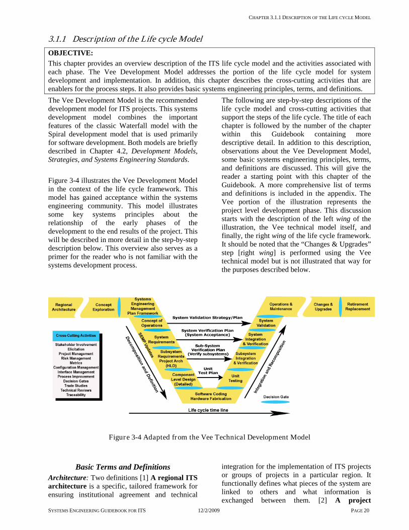
CHAPTER 3.1.1 DESCRIPTION OF THE LIFE CYCLE MODEL
SYSTEMS ENGINEERING GUIDEBOOK FOR ITS 12/2/2009 PAGE 20
3.1.1 Descr iption of the Life cycle Model OBJECTIVE: This chapter provides an overview description of the ITS life cycle model and the activities associated with each phase. The Vee Development Model addresses the portion of the life cycle model for system development and implementation. In addition, this chapter describes the cross-cutting activities that are enablers for the process steps. It also provides basic systems engineering principles, terms, and definitions. The Vee Development Model is the recommended development model for ITS projects. This systems development model combines the important features of the classic Waterfall model with the Spiral development model that is used primarily for software development. Both models are briefly described in Chapter 4.2, Development Models, Strategies, and Systems Engineering Standards. Figure 3-4 illustrates the Vee Development Model in the context of the life cycle framework. This model has gained acceptance within the systems engineering community. This model illustrates some key systems principles about the relationship of the early phases of the development to the end results of the project. This will be described in more detail in the step-by-step description below. This overview also serves as a primer for the reader who is not familiar with the systems development process.
The following are step-by-step descriptions of the life cycle model and cross-cutting activities that support the steps of the life cycle. The title of each chapter is followed by the number of the chapter within this Guidebook containing more descriptive detail. In addition to this description, observations about the Vee Development Model, some basic systems engineering principles, terms, and definitions are discussed. This will give the reader a starting point with this chapter of the Guidebook. A more comprehensive list of terms and definitions is included in the appendix. The Vee portion of the illustration represents the project level development phase. This discussion starts with the description of the left wing of the illustration, the Vee technical model itself, and finally, the right wing of the life cycle framework. It should be noted that the “Changes & Upgrades” step [right wing] is performed using the Vee technical model but is not illustrated that way for the purposes described below.
Figure 3-4 Adapted from the Vee Technical Development Model
Basic Terms and Definitions Architecture: Two definitions [1] A regional ITS architecture is a specific, tailored framework for ensuring institutional agreement and technical
integration for the implementation of ITS projects or groups of projects in a particular region. It functionally defines what pieces of the system are linked to others and what information is exchanged between them. [2] A project

CHAPTER 3.1 OVERVIEW OF THE LIFE CYCLE MODEL FOR INTELLIGENT TRANSPORTATION SYSTEMS
SYSTEMS ENGINEERING GUIDEBOOK FOR ITS 12/2/2009 PAGE 21
architecture is a project-specific description of both logical and physical elements arranged in a hierarchical form showing inter-connections among the elements. It has enough definition that component level detailed design specifications can be written and developed. System: An integrated composite of people, products, and processes which provide a capability to satisfy a stated need or objective. Systems Engineering: An inter-disciplinary approach and a means to enable the realization of successful systems. Systems engineering requires a broad knowledge, a mindset that keeps the big picture in mind, a facilitator, and a skilled conductor of a team. FHWA Final Rule: The FHWA Rule on Architecture Standards and Conformity [Final Rule], also referred to as 23 CFR 940, requires that regional ITS architectures and all ITS projects using Federal funds be developed using a systems engineering analysis. The systems engineering analysis includes: identification of the portion of the RA being implemented, participating agencies roles and responsibilities, requirements definition, alternatives analysis, procurement options, identification of applicable ITS standards and testing procedures, and procedures and resources for system operations and management.
Chapter 3.2.1 to 3.8.1 Process Activities The following is a summary of the process steps in the Vee technical model. Interfacing with Planning and the regional ITS architecture [3.2.1] This initial step interfaces with the ITS architecture for a region. Development of a regional ITS architecture is not covered by this Guidebook since it is well described in the Regional ITS Architecture Guidance Document. Key activities of this phase are: 1] the identification of the regional stakeholders and 2] the building of consensus for the purposes of information sharing and long term operations & maintenance. The architecture is coordinated with the long range transportation plan and candidate ITS projects are programmed through the Transportation Improvement Program, Statewide Transportation Improvement Program, and agency capital plans. For more information on developing a regional ITS architecture please refer to Regional ITS Architecture Guidance Document at: http://www.its.dot.gov/arch/index.htm. Needs Assessment, Concept Exploration & Benefits Analysis [3.3.1 & 3.3.2]
Concept Exploration is used to perform an initial feasibility & benefits analysis and needs assessment for the candidate projects from the regional ITS architecture. This results in a business case and specific cost benefit analyses for alternative project concepts. The output of this stage is a definition of the problem space, key technical metrics, and refinements to the needs, goals, objectives, and vision. This stage identifies the highest cost/benefit concept [best business case] project to move forward into development. This activity may result in combining or dividing candidate projects based on the best cost/benefit analysis. The decision gate is to gain management support & approval for the project to move into the planning and definition phases of the project. Systems Engineering Planning [3.4.1 & 3.4.2] Each project that moves forward into development must be planned. Planning takes place in two parts. In part one, the system’s owner develops a set of master plans and schedules that identifies what plans are needed and, at a high level, the schedule for implementation of the project. This becomes the framework for what is developed in part two. In part two, the plans are completed during the steps from the concept of operations to the high level design. These plans, once approved by the system’s owner, become the control documents for completion of the development and implementation of the project. Concept of Operations [3.4.3] Concept of Operations is the initial definition of the system. At this stage, the project team documents the way the envisioned system is to operate and how the envisioned system will meet the needs and expectations of the stakeholders. The envisioned operation is defined from multiple viewpoints consisting of operators, maintainers, and managers. The focus is on how the system will be validated [proof that the envisioned system meets the intended needs]. A refinement of the problem space, definition, needs, goals, expectations, stakeholder lists, and project constraints is placed into the concept of operations document. This document contains the updated, refined summary of work done at the concept exploration phase. System Level Requirements [3.5.1] Requirements are developed for the system. At the system level; the definition of what the system is to do, how well it is to do it, and under what conditions is documented. System requirements are based on the user needs from the Concept of Operations. Requirements do not state how

CHAPTER 3.1 OVERVIEW OF THE LIFE CYCLE MODEL FOR INTELLIGENT TRANSPORTATION SYSTEMS
SYSTEMS ENGINEERING GUIDEBOOK FOR ITS 12/2/2009 PAGE 22
[design statements] the system will be implemented unless it is intended to constrain the development team to a specific solution. High Level Design [Project Architecture] and Sub-system Requirements [3.5.2] The High Level Design stage defines the project level architecture for the system. System level requirements are further refined and allocated [assigned] to the sub-systems of hardware, software, databases, and people. Requirements for each sub-system element are documented the same way as the system level requirements. This process is repeated until the system is fully defined and decomposed. Each layer will have its own set of interfaces defined. Each layer will require an integration step that is needed when the sub-system is developed. The control gate that is used for this final review is sometimes called the Preliminary Design Review [PDR]. Component Level Detailed Design [3.5.3] At the Component Level Detailed Design step the development team defines how the system will be built. Each sub-system has been decomposed into components of hardware, software, database elements, firmware, and/or processes. For these components, Detailed Design specialists in the respective fields create documentation [“build-to” specifications] which will be used to build or procure the individual components. A final check is done on the “build–to” specifications before the design moves forward to the actual coding and hardware fabrication. At this level, the specific commercial off-the-shelf [COTS] hardware and software products are specified. They are not purchased until the review is completed and approved by the system’s owner and stakeholders. The control gate used for this final review is sometimes called the Critical Design Review [CDR]. Hardware/Software Procurement or Development and Unit Test [3.6.1] This stage involves hardware fabrication, software coding, database implementation, and the procurement & configuration of COTS products. This stage is primarily the work of the development team. The system’s owner and stakeholders monitor this process with planned periodic reviews, e.g. code walkthroughs and technical review meetings. Concurrent with this effort, unit test procedures are developed that will be used to demonstrate how the products will meet the detailed design. At the completion of this
stage, the developed products are ready for unit test. Unit Testing [3.6.1] The components from the hardware and software development are verified in accordance with the unit Verification Plan. The purpose of unit testing is to verify that the delivered components match the documented Component Level Detailed Design. This is done by the development team in preparation for the next level of integration. It is also a good review point for the system’s owner and stakeholders. Sub-system Integration and Verification [3.6.2, 3.6.3] At this step, the components are integrated and verified at the lowest level of the sub-systems. The first level of verification is done in accordance with the Verification Plan and is carried out in accordance with the Verification Procedures [step-by-step method for carrying out the verification] developed in this stage. Prior to the actual verification, a Test Readiness Review is held to determine the readiness of the sub-systems for verification. When it has been determined that verification can proceed, the sub-systems are then verified. When the integration and verification is completed, the next level of sub-system is integrated and verified in the same manner. This process continues until all sub-systems are integrated and verified. System Verification [3.6.3] System Verification is done in two parts. The first part is done under a controlled environment [sometimes called a “factory test”]. The second part is done within the environment that the system is intended to operate [sometimes called “on-site testing/verification”] after initial system deployment. At this stage, the system is verified in accordance with the Verification Plan developed as part of the system level requirements performed early in the development. The system acceptance will continue through the next stage, Initial System Deployment. The final part of System Verification is then completed. A control gate is used for this conditional system acceptance. Initial System Deployment [3.6.4] At Initial System Deployment, the system is finally integrated into its intended operational environment. This step may take several weeks to complete to ensure that the system operates satisfactorily in the long term. This is sometimes called a “system burn-in”. Many system issues

CHAPTER 3.1 OVERVIEW OF THE LIFE CYCLE MODEL FOR INTELLIGENT TRANSPORTATION SYSTEMS
SYSTEMS ENGINEERING GUIDEBOOK FOR ITS 12/2/2009 PAGE 23
surface when the system is operating in the real world environment for an extended period of time. This is due to the uncontrollable nature of inputs to the system, such as long term “memory” leaks in software coding and race conditions [unexpected delays between signals] that may only occur under specific and infrequent conditions. Once the System Verification is completed, the system is accepted by the system’s owner and stakeholders and then moves into the System Validation and Operations & Maintenance phases. System Validation [3.7.1] Validating the system is a key activity of the system’s owner and stakeholders. It is here that they will assess the system’s performance against the intended needs, goals, and expectations documented in the Concept of Operations and the Validation Plan. It is important that this validation takes place as early as possible [after the acceptance of the system] in order to assess its strengths, weaknesses, and new opportunities. This activity does not check on the work of the system integrator or the component supplier [that is the role of System Verification]. It is performed after the system has been accepted and paid for. As a result of validation, new needs and requirements may be identified. This evaluation sets the stage for the next evolution of the system. Operations & Maintenance [3.7.2] After the initial deployment and system acceptance, the system moves into the Operations & Maintenance phase. In this phase the system will carry out the intended operations for which it was designed. During this phase routine maintenance is performed as well as staff training. This phase is the longest phase, extending through the evolution of the system and ends when the system is retired or replaced. This phase may continue for decades. It is important that there are adequate resources to carry out the needed Operations & Maintenance activities; otherwise, the life of the system could be significantly shortened due to neglect. Changes & Upgrades [3.7.3] Changes & Upgrades should be implemented in accordance with the Vee technical process recommended by this Guidebook. Using the Vee process for changes & upgrades will help maintain system integrity [synchronization between the system components and supporting documentation]. When the existing system is not well documented, start by reverse engineering the affected area of the system in order to develop the
needed documentation for the forward engineering process. Retirement/Replacement [3.8.1] Eventually, every ITS system will be retired or replaced for one of the following reasons: • The system may no longer be needed. • It may not be cost effective to operate. • It may no longer be maintainable due to
obsolescence of key system elements. • It might be an interim system that is being
replaced by a more permanent system. This phase looks at how to monitor, assess needed changes, and make change/upgrade decisions. Cross-Cutting Activities [3.9] A number of cross-cutting activities are needed to support the development of Intelligent Transportation Systems. The following are the enabling activities used to support one or more of the life-cycle process steps. Stakeholder Involvement [3.9.1] Stakeholder involvement is regarded as one of the most critical enablers within the development and life-cycle of the project and system. Without effective stakeholder involvement, the systems engineering and development team will not gain the insight needed to understand the key issues and needs of the system’s owner and stakeholders. This increases the risk of not getting a valid set of requirements to build the system or to obtain buy-in on changes & upgrades. Elicitation [3.9.2] Elicitation is an activity that when performed correctly, effectively, and accurately, gathers and documents information needed to develop the system. The typical types of information include needs, goals, objectives, requirements, and stakeholder expectations. Some information may be in a documented form or stated clearly by the stakeholders, but much of the needed information may be implied or assumed. The elicitation processes help draw out and resolve this information, resolve conflicting information, build consensus, and validate the information. Project Management Practices [3.9.3] Various project management practices are needed to support the development of the system. Project management practices provide a supportive environment for the various development activities. It provides the needed resources, then monitors and controls costs and schedules. It also communicates status between and across the
CHAPTER 3.1 OVERVIEW OF THE LIFE CYCLE MODEL FOR INTELLIGENT TRANSPORTATION SYSTEMS
SYSTEMS ENGINEERING GUIDEBOOK FOR ITS 12/2/2009 PAGE 24
development team members, system’s owner, and stakeholders. Risk Management [3.9.4] There will be risks for ITS system development efforts. Risk Management is a process used to identify, analyze, plan, and monitor risk. Then, it mitigates, avoids, transfers, or accepts those risks. Project Metrics [3.9.5] Project metrics are measures that are used by both the project manager and systems engineer to track and monitor the project and the expected technical performance of the system development effort. The identification and monitoring of metrics allow the team to determine if the project is “on-track” both programmatically and technically. Configuration Management [3.9.6] Managing change to the system is a key process that occurs throughout the life of the system. Configuration management is the process that supports the establishment of system integrity [the documentation matches the functional and physical attributes of the system]. It maintains this integrity throughout the life of the system [synchronizes changes to the system with its documentation]. A lack of change management will shorten the life of the system and may prevent a system from being implemented and deployed. Process Improvement [3.9.7] A quality aspect of the system’s life cycle is to continuously improve the process. This is done by learning from previous efforts how to improve future work. Process Improvement is an enabler that provides insight about what worked and what needs improvement in the processes. This activity is used to improve the documented processes over time. Decision Gates [3.9.8] Decision Gates are formal decision points along the life cycle that are used by the system’s owner and stakeholders to determine if the current phase of work has been completed and if the team is ready to move onto the next phase of the life cycle. By setting entrance and exit criteria for each phase of work, the control gates are used to review and accept the work products done for the current phase of work. They also evaluate the readiness for moving to the next phase of the project.
Decision Support/Trade Studies [3.9.9] Technical decisions on alternative solutions are a key enabler for each phase of system development. This starts when alternative concepts are evaluated and continues through the system definition and design phases. This chapter provides a method to perform a trade study. Technical Reviews [3.9.10] Technical reviews are used to assess the completeness of a product, identify defects in work, and align team members in a common technical direction. This chapter provides a process for conducting a technical review. Traceability [3.9.11] Traceability is a key cross-cutting process that supports verification & validation of requirements by ensuring that all needs are traced to requirements and that all requirements are implemented, verified, and validated. Traceability supports impact analysis for changes, upgrades, and replacement.
Key Observations for the Vee Development Model
1. The left side is the definition and decomposition of the system into components that can be built or procured. The bottom of the Vee is the construction, fabrication, and procurement of the component items. The right side of the Vee integrates the components into sub-systems then into the final system. Each level of integration is verified against the left side of the Vee through the Verification Plans [verification process [3.6.3] ].
2. Decision gates [3.9.8] provide the system’s owner with formal decision points for proceeding to the next step of the process. A decision gate is an interface from one phase of the project to the next. There is an interface between each phase from the left side to the right side.
3. There is a relationship of the activities performed on the left side of the Vee to the products being produced, integrated, and verified on the right side of the Vee [model versus reality].
4. The most important view of the system for the system’s owner and stakeholders is at the Concept of Operations level. Below that level is the area of most interest to the development team. It is the area for which they are

CHAPTER 3.1 OVERVIEW OF THE LIFE CYCLE MODEL FOR INTELLIGENT TRANSPORTATION SYSTEMS
SYSTEMS ENGINEERING GUIDEBOOK FOR ITS 12/2/2009 PAGE 25
responsible [system’s owner responsibility versus the development team responsibility].
5. Importance of stakeholder involvement is shown on both sides of the Vee. It is shown on the left side by defining the system and on the right side by the verification of the system.
Some Basic Systems Engineering Principles The Systems Engineer should have the following mindset when developing a system: 1. View the system from the stakeholder point of
view [walk in the shoes of the system’s owner and stakeholders]. Key processes include needs assessment, elicitation, Concept of Operations, and stakeholder involvement.
2. Start at the finish line to define the output of the system and the way the system is going to operate. Key processes include Concept of Operations and Validation Plan.
3. Address risks as early as possible when the cost impacts are lowest. Key processes
include risk management, requirements, and stakeholder involvement [spend more time on the left side of the Vee].
4. Push technology choices to the last possible moment. Define what is to be done before defining how it is to be done [form follows function].
5. Focus on interfaces of the system during the definition of the system. Defining clear and standard interfaces and managing them through the development will ease the integration of the individual elements of the system.
6. Understand the organization of the system’s owner, stakeholders, and development team. Phases, Tasks, Activities and Products
Table 3-1 to Table 3-5 provide an overview of the typical tasks, activities products, and decision gates that are associated with each phase of the development life cycle.

CHAPTER 3.1 OVERVIEW OF THE LIFE CYCLE MODEL FOR INTELLIGENT TRANSPORTATION SYSTEMS
SYSTEMS ENGINEERING GUIDEBOOK FOR ITS 12/2/2009 PAGE 26
Table 3-1 Phase [-1] & 0 Tasks, Activities Products, Decision Gates
Phase Phase [-1]
Regional Architecture Phase 0
Concept Exploration
Chapter 3.2.1 3.3.1 3.3.2
Tasks Interfacing with
Planning and the Regional ITS Architecture
Needs Assessment Concept Exploration and Benefits Analysis
Act
iviti
es
• Identify Regional ITS architectures and other resources
• Identify portion of regional architecture for the project
• Check consistency & submit architecture changes
• Identify stakeholders • Elicit needs • Document needs • Validate needs • Prioritize needs • Perform gap
analysis • Compare costs
• Define vision • Define goals &
objectives • Identify constraints • Define evaluation
criteria • Identify candidate
solutions • Identify alternative
concepts • Evaluate alternative
concepts • Document results
Prod
ucts
• Portion of the regional ITS architecture for the project
• Recommended regional ITS architecture changes
• Prioritized set of stakeholder needs
• Stakeholders • Relative costs
• Recommended system concept
• System Concept Exploration rationale
• Benefits report
Decision Gates • Project Approval

CHAPTER 3.1 OVERVIEW OF THE LIFE CYCLE MODEL FOR INTELLIGENT TRANSPORTATION SYSTEMS
SYSTEMS ENGINEERING GUIDEBOOK FOR ITS 12/2/2009 PAGE 27
Table 3-2 Phase 1 Tasks, Activities, Products, Decision Gates
Phase Phase 1
Project Planning & Concept of Operations
Chapter 3.4.1 3.4.2 3.4.3
Tasks Project Planning Systems Engineering Management Planning Concept of Operations
Act
iviti
es
• Define & budget all project tasks
• Identify needed resources
• Make procurement decisions
• Develop project schedule
• Prepare Project Plan
• Prepare necessary supporting management plans
• Assess project management activities and technical tasks
• Transitioning critical technologies
• Define needed systems engineering processes and resources
• Make procurement decisions and specify integration activities
• Prepare Systems Engineering Management plan and supporting plans (as needed)
• Define project vision, goals, and objectives
• Explore project concepts
• Develop operational scenarios
• Develop and document project Concept of Operations
Prod
ucts
• Project Plan • Supporting
management plans • Requests for
proposals
• Systems Engineering Management Plan
• Supporting technical plans
• Requests for proposals
• Concept of Operations document
• Validation Plan
Decision Gates • Project Plan • SEMP Framework • Concept of
Operations

CHAPTER 3.1 OVERVIEW OF THE LIFE CYCLE MODEL FOR INTELLIGENT TRANSPORTATION SYSTEMS
SYSTEMS ENGINEERING GUIDEBOOK FOR ITS 12/2/2009 PAGE 28
Table 3-3 Phase 2 Tasks, Activities, Products, Decision Gates
Phase Phase 2
System Definition and Design
Chapter 3.5.1 3.5.2 3.5.3
Tasks Requirements Development High Level Design Component Level Detailed
Design
Act
iviti
es
• Develop Requirements
• Write & document requirements
• Check completeness
• Analyze, refine & decompose requirements
• Validate requirements
• Manage requirements
• Develop, decompose, and evaluate project level architecture alternatives
• Identify and evaluate internal and external interfaces
• Evaluate industry standards
• Select & document the high level design
• Perform preliminary design review
• Evaluate COTS commercial off the shelf products and applications
• Perform detailed design
• Perform technical reviews
• Perform critical design review
Prod
ucts
• System and sub-system requirements document
• Verification Plan
• High level design document
• Internal and external interfaces
• Select appropriate industry standards
• Sub system verification plans
• Selected COTS products
• Component detailed design document
• Unit Verification Plan
Decision Gates
• System Requirements
• Sub systems requirements • Detailed design

CHAPTER 3.1 OVERVIEW OF THE LIFE CYCLE MODEL FOR INTELLIGENT TRANSPORTATION SYSTEMS
SYSTEMS ENGINEERING GUIDEBOOK FOR ITS 12/2/2009 PAGE 29
Table 3-4 Phase 3 Tasks, Activities, Products, Decision Gates
Phase Phase 3
System Development & Implementation Chapter 3.6.1 3.6.2 3.6.3 3.6.4
Tasks Hardware/Software Development and
Unit Test Integration Verification Initial System
Deployment
Act
iviti
es
• Support, monitor, and review development
• Develop system products
• Coordinate concurrent developments
• Procure COTs
• Plan Integration activities
• Define Integration activities
• Perform integration activities
• Plan Verification activities SEMP/Project Plan
• Develop Verification plan
• Trace between requirements and verification plan
• Develop verification procedures
• Perform Verification
• Document verification results
• Develop Deployment strategy
• Write Deployment Plan
• Perform deployment activities
Prod
ucts
• Develop hardware and software products
• Support products
• Unit verification procedures
• Integration Master plan
• Integration plan • Integrated
system & sub-systems (ready to verify)
• Verification Master Plan
• Verification Plans
• Verification procedures
• Verification report
• Verify sub systems and system products
• Deployment master plan
• Deployment plan • Deploy system
ready for validation, operations
Decision Gates
• Verification Readiness
• Acceptance of sub-system products
• Acceptance of System
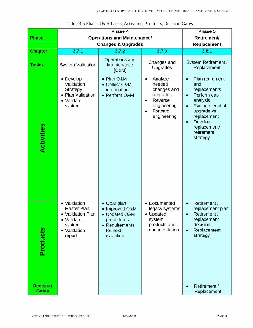
CHAPTER 3.1 OVERVIEW OF THE LIFE CYCLE MODEL FOR INTELLIGENT TRANSPORTATION SYSTEMS
SYSTEMS ENGINEERING GUIDEBOOK FOR ITS 12/2/2009 PAGE 30
Table 3-5 Phase 4 & 5 Tasks, Activities, Products, Decision Gates
Phase Phase 4
Operations and Maintenance/ Changes & Upgrades
Phase 5 Retirement/
Replacement Chapter 3.7.1 3.7.2 3.7.3 3.8.1
Tasks System Validation Operations and Maintenance
[O&M]
Changes and Upgrades
System Retirement / Replacement
Act
iviti
es
• Develop Validation Strategy
• Plan Validation • Validate
system
• Plan O&M • Collect O&M
information • Perform O&M
• Analyze needed changes and upgrades
• Reverse engineering
• Forward engineering
• Plan retirement and replacements
• Perform gap analysis
• Evaluate cost of upgrade vs. replacement
• Develop replacement/ retirement strategy
Prod
ucts
• Validation Master Plan
• Validation Plan • Validate
system • Validation
report
• O&M plan • Improved O&M • Updated O&M
procedures • Requirements
for next evolution
• Documented legacy systems
• Updated system products and documentation
• Retirement / replacement plan
• Retirement / replacement decision
• Replacement strategy
Decision Gates
• Retirement / Replacement

Chapter 3.1.2 Key Milestones and Project Time Table
Systems Engineering Guidebook 12/2/2009 PAGE 31
3.1.2 Key Milestones and Project Time Table
The ITS Project Life cycle on the following pages shows the entire set of systems engineering tasks required for an ITS project. All of these are described in detail in this Guidebook. The entire sequence of systems engineering tasks is grouped into six phases [0 through 5], covering everything from the initial concept exploration to the final system retirement. Each phase includes from one to four tasks. Each task is described according to its major activities, primary products, and control gates. The chapter number in this Guidebook identifies each task. Sequence of Phases, Tasks, and Activities Each of the ITS Project Life cycle phases described in this Guidebook require a specific set of management and engineering skills. In large system development projects, activities within each task may be performed by a different set of people. For most ITS projects, this is not the case. The same individuals may perform several, or even all, of the activities within a task. For these reasons, the phases and tasks in this Guidebook are to be performed sequentially, especially for phases 1 and 2. In these early phases, there is a temptation to start the next task prior to the completion and acceptance by the stakeholders of the current task, this is sometimes called concurrent engineering. For ITS, depending on the complexity of the project this decision to move forward prior to completing a previous phase must be done with great care and in some cases it is not recommended. It might appear that overlapping the tasks can shorten the schedule. But, this introduces significant risks into the project. For example, starting the high level design prior to the development and acceptance of the system level requirements introduces the risk of reworking both. Or worse, the team moves on to detailed design prior to completing either of the previous phases. Within each task, the activities are designed to work together to meet the objectives of that part of work. In some cases, similar activities can show up in different tasks or even phases. For example, prototyping is a primary activity of the detailed design task. Also, prototyping is often done at the concept of operations and requirement development stage to ensure the feasibility of the concept or requirements and to validate concepts and requirements to the stakeholders.
Relative Durations of System Development Tasks The following discussion only considers the duration of the system development activities. That includes the phases following Concept Exploration; culminating in Operations & Maintenance. System development refers to phases 1, 2, and 3 as illustrated in Figure 3-5. A detailed list of tasks, activities, products, and control gates is located in this chapter. Tasks performed before and after system development are subject to too great of variation [both for institutional and operations reasons] to make any generalizations on their duration meaningful. Roughly speaking, phase 1 [Project Planning and Concept of Operations] takes about 10% of the total project duration, phase 2 [System Definition] about 30%, phase 3 [System Development and Implementation] about 50% and on going project management approximately 10%. These relative levels of duration are useful as a rule-of-thumb or a reality check. The duration of every individual project must eventually be estimated on a bottom-up basis. That is, each individual task must be described in an appropriate level of detail. Then the time required for each task must be estimated based on the complexity of the individual task within the context of the specific project. Only then can a reasonably realistic schedule for a project be compiled. The following is a detailed look at each of the phases, inputs, outputs, enablers, and controls for each activity. Phase [-1]: Figure 3-6 Phase [-1] - Interfacing with the Regional Architecture Phase 0: Figure 3-7 Phase 0 - Concept Exploration and Benefits Analysis Roadmap Phase 1: Figure 3-8 Phase 1 - Project Planning and Concept of Operations Development Roadmap Phase 2: Figure 3-9 Phase 2 - System Definition Roadmap Phase 3: Figure 3-11 Phase 3 - System Development and Implementation Roadmap Phase 4: Figure 3-14 Phase 4 - Validation, O&M, Changes & Upgrades Roadmap Phase 5: Figure 3-15 Phase 5 - System Retirement and/or Replacement Roadmap

CHAPTER 3.1.2 KEY MILESTONES AND PROJECT TIME TABLE
Systems Engineering Guidebook 12/2/2009 PAGE 32
Figure 3-5 Roadmap through Chapter 3 of the Guidebook

CHAPTER 3.1.2 KEY MILESTONES AND PROJECT TIME TABLE
Systems Engineering Guidebook 12/2/2009 PAGE 33
3.2 Inter facing to the Regional Architecture
Figure 3-6 Phase [-1] - Interfacing with the Regional Architecture

CHAPTER 3.2.1 INTERFACING WITH PLANNING AND THE REGIONAL ITS ARCHITECTURE
Systems Engineering Guidebook 12/2/2009 PAGE 34
3.2.1 Inter facing with Planning and the Regional ITS Architecture
OBJECTIVE: Intelligent Transportation Systems at the project level are to be consistent with, and leverage from, the regional ITS architecture. The regional ITS architecture provides a framework that supports transportation planning and programming for ITS projects. This step describes what to expect from the regional ITS architecture and how to use the products at the project level. An existing regional ITS architecture provides products that can be leveraged for concept exploration, feasibility analysis, and project level developments.
DESCRIPTION: Before the project level development begins, groundwork is laid in the planning process and the development of a regional ITS architecture. The regional ITS architecture includes a list of stakeholders, a system inventory, an identification of regional needs and transportation services that meet those needs, a high-level operational concept, functional requirements, and regional interconnections and information exchanges. The project will refine and expand products from the regional ITS architecture. For example, it may expand an agency-level stakeholder to identify maintenance, IT, and operations divisions that were not specified at the regional level. As the project is defined, additional needs and approaches may be identified that were not envisioned at the regional level. Providing feedback to the planning process and the regional ITS architecture is essential so that the regional ITS architecture continues to provide an accurate high-level depiction of ITS implementation and vision for the region.
CONTEXT OF PROCESS
PROCESS FOR INTERFACING WITH PLANNING AND THE REGIONAL ITS
ARCHITECTURE

CHAPTER 3.2.1 INTERFACING WITH PLANNING AND THE REGIONAL ITS ARCHITECTURE
Systems Engineering Guidebook 12/2/2009 PAGE 35
Inputs: Regional ITS architectures describe the framework for integration. The project must fit into these architectures or the architectures must be changed to reflect new regional consensus. Project goals and objectives identify the purpose of the project and what it is intended to accomplish.
Control: FHWA Final Rule and FTA Policy specifies the requirements for developing and maintaining a regional ITS architecture and the requirements for using a systems engineering analysis for ITS projects.
Enablers: Stakeholder involvement focuses the project on local needs. Elicitation draws out and clarifies local project needs.
Outputs: Portion of the regional ITS architecture identifies the parts of the regional ITS architecture selected for development on this project. This output defines the basic scope of the project in context with other ITS systems that exist or will exist in the region. Recommended regional ITS architecture changes should be submitted to the architecture maintainer for consideration in future updates to the regional ITS architecture.
Process Activities: Identify existing regional ITS architectures and other resources from the planning process. Many states and regions have developed state and regional ITS architectures. These architectures provide a good starting point for project development and must be used to support project systems engineering analysis, per the FHWA Rule/FTA Policy. In some cases, more than one regional ITS architecture may apply. For example, a major metropolitan area may be included in a statewide architecture, a regional architecture for the metropolitan area, and sub-regional architectures that are developed for a particular agency or jurisdiction. Identify the regional ITS architecture that applies to the project, coordinating with the architecture maintainers in the region as necessary. Coordinate with Planning to take advantage of all previous work that has been done. Identify the portion of the regional ITS architecture for the project. Any given ITS project will implement only a small subset of the regional ITS architecture. The regional ITS architecture necessarily addresses many regional needs and issues that are outside the scope of the project. For example, in a simple signal system that does not interface with ramp meters, the aspects of the regional ITS architecture that address freeways are not relevant. The first step is to identify the portion of the regional ITS architecture that applies to the project. Using this subset of the regional ITS architecture, document any constraints that the architecture may place on the design, including ITS standards that are identified that may be applicable to the project. Using a regional ITS architecture will provide a project that is consistent with other systems in the area, meets requirements for federal funding, and can be developed more efficiently and quickly using the regional ITS architecture content to get started. A good regional ITS architecture will provide region-level information that can be used and expanded in the project development, providing a good starting point for concept exploration and initial project development. Check consistency and submit architecture changes. Confirm that the project fulfills a portion of the regional ITS architecture. If the project provides capabilities beyond the regional ITS architecture, the regional ITS architecture should be updated to more accurately reflect the ITS project. These changes should be submitted to the maintainer of the architecture.
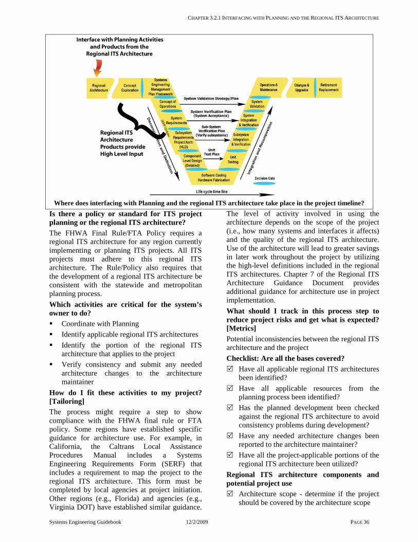
CHAPTER 3.2.1 INTERFACING WITH PLANNING AND THE REGIONAL ITS ARCHITECTURE
Systems Engineering Guidebook 12/2/2009 PAGE 36
Where does interfacing with Planning and the regional ITS architecture take place in the project timeline?
Is there a policy or standard for ITS project planning or the regional ITS architecture? The FHWA Final Rule/FTA Policy requires a regional ITS architecture for any region currently implementing or planning ITS projects. All ITS projects must adhere to this regional ITS architecture. The Rule/Policy also requires that the development of a regional ITS architecture be consistent with the statewide and metropolitan planning process. Which activities are critical for the system’s owner to do? Coordinate with Planning Identify applicable regional ITS architectures Identify the portion of the regional ITS
architecture that applies to the project Verify consistency and submit any needed
architecture changes to the architecture maintainer
How do I fit these activities to my project? [Tailoring] The process might require a step to show compliance with the FHWA final rule or FTA policy. Some regions have established specific guidance for architecture use. For example, in California, the Caltrans Local Assistance Procedures Manual includes a Systems Engineering Requirements Form (SERF) that includes a requirement to map the project to the regional ITS architecture. This form must be completed by local agencies at project initiation. Other regions (e.g., Florida) and agencies (e.g., Virginia DOT) have established similar guidance.
The level of activity involved in using the architecture depends on the scope of the project (i.e., how many systems and interfaces it affects) and the quality of the regional ITS architecture. Use of the architecture will lead to greater savings in later work throughout the project by utilizing the high-level definitions included in the regional ITS architectures. Chapter 7 of the Regional ITS Architecture Guidance Document provides additional guidance for architecture use in project implementation. What should I track in this process step to reduce project risks and get what is expected? [Metrics] Potential inconsistencies between the regional ITS architecture and the project Checklist: Are all the bases covered? Have all applicable regional ITS architectures
been identified? Have all applicable resources from the
planning process been identified? Has the planned development been checked
against the regional ITS architecture to avoid consistency problems during development?
Have any needed architecture changes been reported to the architecture maintainer?
Have all the project-applicable portions of the regional ITS architecture been utilized?
Regional ITS architecture components and potential project use Architecture scope - determine if the project
should be covered by the architecture scope

Chapter 3.2 17BInterfacing to the Regional Architecture
SYSTEMS ENGINEERING GUIDEBOOK 12/2/2009 PAGE 37
Stakeholder identification – Ensure appropriate agencies are involved. Expand list to identify specific divisions, groups, etc. that should be involved.
System inventory - Identify the system(s) that will be implemented or enhanced by the project. Also identify interfacing systems that may be impacted.
Needs and services - Confirm that the project will address the regional needs and services documented in the architecture. Identify the ITS service(s) that are supported by the project and related regional needs.
Operational concept – Expand on the broad agency roles and responsibilities identified in the architecture to define specific roles and responsibilities for development and the operations & maintenance of the project in the Concept of Operations.
Functional requirements – Use the high-level functional requirements from the architecture as a starting-point for the project system requirements. Project system requirements will add specificity, detail, and include other types of requirements.
Interfaces/information flows – Review the interfaces defined in the architecture to identify integration opportunities that should be addressed in the current project and/or accounted for in future iterative development. Identify and define selected interfaces in increasing detail during project development.
Maintenance plan – Submit needed architecture changes or enhancements to the architecture maintainer through the identified process.
Agreements – The list of agreements may include existing and planned agreements that are necessary for the project. Define any agreements that are necessary for the project and begin work immediately on these long lead-time documents.
Standards identification – The ITS standards identified in the architecture will provide a comprehensive list of national ITS standards that will have to be tailored to include only standards (and the portion of standards) that are actually relevant to the project and also augmented to include regional and project-level standards that may also apply.
Project sequencing - If the sequence of projects in the architecture includes the target project, this will facilitate identifying the
portion of the regional ITS architecture that applies. If not, the need for an update to the project sequencing can be reported to the architecture maintenance organization.
Are there any recommendations that can help? The regional ITS architecture is often developed using the Turbo Architecture software, which structures the information, and provides a link with the National ITS Architecture. If Turbo Architecture is available, this tool can also be used to select the subset of the regional ITS architecture that applies to the project through it’s project architecture capability. The relevant portion of the regional ITS architecture can be exported as diagrams, reports, or textual files that can then be incorporated into the initial project documentation.
Several States have developed a statewide ITS architecture that provides a framework that covers the entire state, covering gaps between
regional ITS architectures that are frequently focused on the metropolitan areas. The statewide architectures focus on state level services, such as commercial vehicle operations, or services that benefit from interregional coordination, such as trip planning. Projects that implement these broader services should be related to the statewide architecture, if one exists. The goal is to complement the activities of the metropolitan planning organizations by creating a framework for connections between regions and state-level services. The process requires consensus building among a diverse group of stakeholders representing the varied interests throughout the state. Challenges to traditional planning and ITS project development Coordination between planning and operations is essential in regional ITS architecture development. The ITS projects that are identified in the long range transportation plan and the Transportation Improvement Program [TIP must meet the purpose and needs identified through planning, be operationally viable, and be maintainable through the project’s life cycle. Considering each of these factors early in project development requires the combined expertise from many domains, including planning, operations, and maintenance. The regional ITS architecture also provides a project sequence that can be used as a tool to define the relationship and dependencies between projects early in the process.

Chapter 3.3 Concept Exploration and Benefits Analysis
Systems Engineering Guidebook 12/2/2009 PAGE 38
3.3 Concept Exploration and Benefits Analysis
Figure 3-7 Phase 0 - Concept Exploration and Benefits Analysis Roadmap
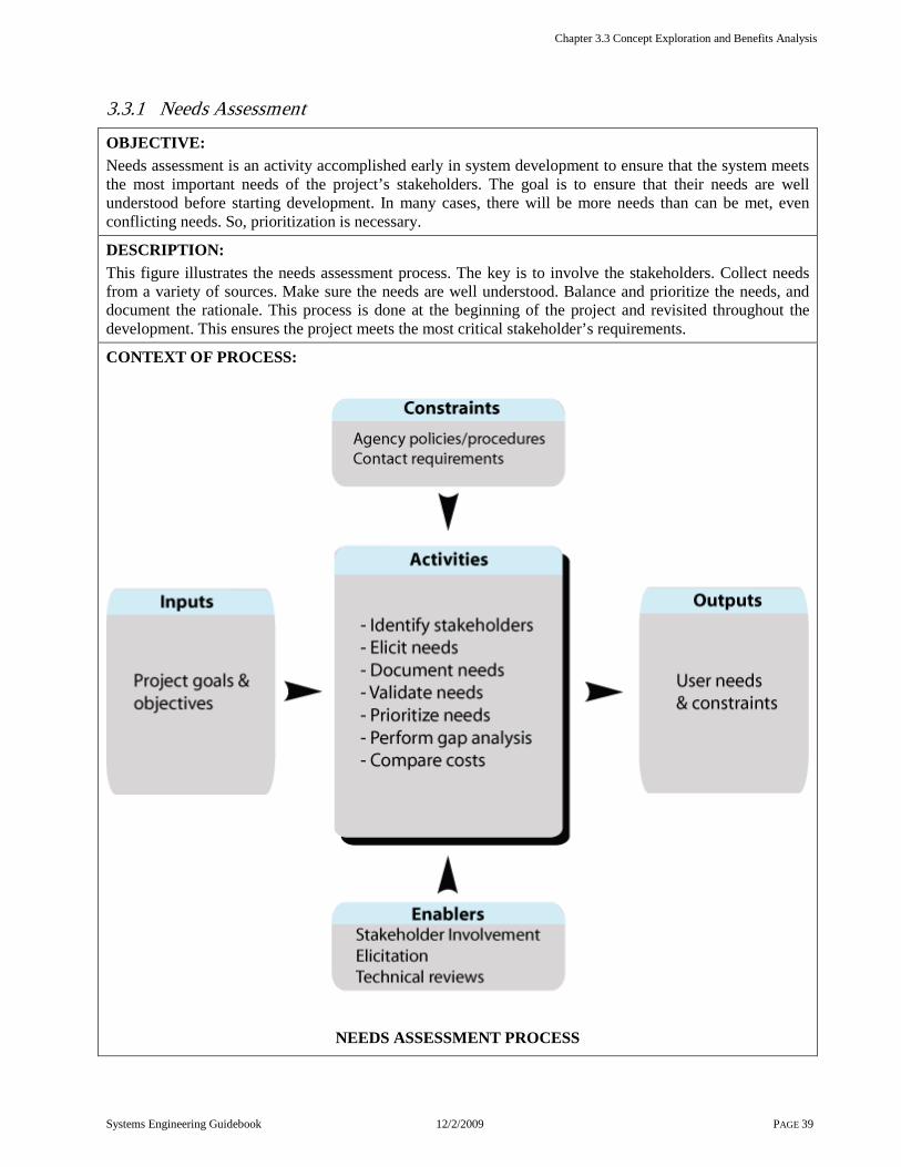
Chapter 3.3 Concept Exploration and Benefits Analysis
Systems Engineering Guidebook 12/2/2009 PAGE 39
3.3.1 Needs Assessment
OBJECTIVE: Needs assessment is an activity accomplished early in system development to ensure that the system meets the most important needs of the project’s stakeholders. The goal is to ensure that their needs are well understood before starting development. In many cases, there will be more needs than can be met, even conflicting needs. So, prioritization is necessary.
DESCRIPTION: This figure illustrates the needs assessment process. The key is to involve the stakeholders. Collect needs from a variety of sources. Make sure the needs are well understood. Balance and prioritize the needs, and document the rationale. This process is done at the beginning of the project and revisited throughout the development. This ensures the project meets the most critical stakeholder’s requirements.
CONTEXT OF PROCESS:
NEEDS ASSESSMENT PROCESS

Chapter 3.3 Concept Exploration and Benefits Analysis
Systems Engineering Guidebook 12/2/2009 PAGE 40
Inputs: Project Goals and Objectives are the major drivers for defining the needs. This is an output of the planning process [3.2.1]. Previous studies, including feasibility studies and strategic plans, are good sources for documented needs.
Control: Agency policies and procedures will constrain the process to meet its legal, risk, and institutional obligations.
Enablers: Stakeholder involvement is essential to defining valid and meaningful needs. Technical reviews are an effective means to get stakeholder feedback about the needs being collected. Elicitation uses various techniques to elicit, clarify, and prioritize needs. Trade studies provide an analytical basis for the prioritization of needs.
Outputs: Key needs and constraints the list of collected needs, their sources, and documentation of the rationale for the selection of the key needs and any constraints which exist that may limit possible solutions to the needs. This may be a separate document, or incorporated as part of the Concept of Operations.
Process Activities: Identify stakeholders Identify the stakeholders who will own, operate, maintain, use, interface with, benefit from or otherwise be affected by the system. Elicit needs Needs assessment must set aside any preconceived notions of what the system will do. It then elicits the stakeholders’ needs, desires, and constraints by various means, as described in 3.8.2. Some of the techniques are literature search, day-in-the-life studies, surveys, one-on-one interviews, and workshops. Document needs Consolidate the results of the elicitation process into a document. If there are many stakeholders it may be helpful to summarize the results, e.g., 75% of the local agencies cited a need for real-time freeway speed data. It is important to include all constraints, such as the restrictions on data sharing. Validate needs Present the consolidated results to the stakeholders. This is best done in a workshop where the stakeholders are encouraged to give feedback and have discussions. Continue the discussions until they agree all of their needs have been captured. Prioritize needs Generally, all of the needs cannot be met and, sometimes, may be conflicting. Analysis of the needs identifies the highest priority needs on which to focus. This may be done by a priorities analysis, surveys, or consensus. Perform gap analysis Inventory current systems that may contribute to fulfilling the identified needs. Rank each need in terms of both the breadth [e.g., 70% of the freeways currently collect speed data] and depth [criticality] of the gap between current and desired capabilities. Compare costs Estimate the cost to meet each of the needs. Qualitative estimates may be sufficient, such as high/medium/low, or easy/moderate/difficult to implement. Validate key needs Taking into account the priorities [gaps and costs], identify the most pressing needs. Document them and the rationale behind them. Present these conclusions to the stakeholders for discussion and concurrence. Modify key needs as warranted. Update the documentation.

Chapter 3.3 Concept Exploration and Benefits Analysis
Systems Engineering Guidebook 12/2/2009 PAGE 41
Where does the Needs Assessment take place in the project timeline?
Is there a policy or standard for Needs Assessment? FHWA Final Rule does not specifically mention general Need Assessment practices to be followed. However, gathering and assessing needs is an essential part of developing a set of valid requirements, which is required by the FHWA Final Rule. Which activities are critical for the system’s owner to do? Provide the initial statement of needs. Provide data and information on current
system capabilities relative to the needs. Supply any existing documentation of needs. Identify the stakeholders and encourage their
inputs. Participate in any interviews, surveys,
workshops, or other activities developed for the identification, clarification, and prioritization of needs.
Review statements of needs. How do I fit these activities to my project? [Tailoring] These activities are especially important when there are multiple agencies involved, especially if they have different priorities or have not worked together previously. In that case, it is essential to get documented agreements on the direction in order to prevent future contention. The larger the number of agencies involved, the more risk there is for conflicting needs and incompatible operations. Hence, the amount of effort expended
on needs assessment and prioritization should grow with the number of agencies. On the other hand, a single agency project based on well-defined and limited needs may not need to do extensive prioritizing of user needs. A one-page needs statement may be sufficient. This is the case for many small projects, such as a signal system projects. What should I track in this process step to reduce project risks and get what is expected? [Metrics] On the technical side: Level of disagreement among stakeholders on
high priority needs, since it risks producing a system whose purpose is unfocused and satisfies no one
Percentage of the important needs that cannot be met within the budget, since such needs may motivate scope creep
Number of expressed needs that are in conflict, since they must be resolved before proceeding
On the project management side: Number of stakeholders whose needs have
been captured Number of stakeholders who agree with the
final selection of key needs Checklist: Are all the bases covered? Have all relevant stakeholders been
represented?
Chapter 3.3 Concept Exploration and Benefits Analysis
SYSTEMS ENGINEERING GUIDEBOOK FOR ITS 12/2/2009 PAGE 42
Have all appropriate resources been utilized to elicit needs?
Have all collected needs and conclusions been reviewed with the stakeholders?
Is there an objective and justifiable approach for prioritizing needs?
Are conclusions and rationale well documented?
Have all stakeholders agreed that their needs are clearly and fairly represented?
Are there any recommendations that can help? Getting the needs right up front prevents expensive backtracking later on, when changes are much more expensive.
There are professional facilitators who can come in to encourage people to work together and to explore new ideas. This might be helpful if there are multiple agencies involved in a project with conflicting needs. There are also techniques that help to draw out, organize, and analyze needs.
Be sure to capture the constraints as well as the needs. A constraint for a single stakeholder, such as the maximum height of maintenance’s
bucket trucks, will impact the system for all. State policy needs to be considered here. For example, if it prohibits installing private utility lines longitudinally in freeway right-of-way, that will constrain the possible approaches. Be sure the constraints flow into the requirements. A closer look at Prioritizing needs Prioritizing needs early is important to prevent making hard decisions later on when it is discovered that not all of the needs can be met within the budget and schedule. When various stakeholder's have their own favorites there must be a sensitivity to this and a balance must be reached if these favorites conflict. One way to do this is through an objective priority analysis and defined consensus process. This will ensure that all stakeholder needs are given fair consideration. The following techniques can be used to support prioritizing of user needs: to draw needs out of previous project
documents and prioritize them with concurrence of the stakeholders
conduct a workshop in which stakeholders review and rank candidate needs
use surveys define a decision process [e.g., multi-voting,
majority, and negotiation]
These techniques are discussed in the Trade Studies chapter [Ch. 3.9.9], under the heading, “Making qualitative measures quantitative.” Once the needs have been identified, the gap between current capabilities and the needs are determined. This gap analysis technique makes qualitative judgments numerical, so that they can be compared. Projects are seldom built as a completely stand-alone system, but rely and are built upon legacy systems. The first step in the process is to determine how far the current capabilities are from meeting the needs because of insufficient functionality, capabilities, performance, or capacity. This is the “depth” of the gap. It may be qualitatively assessed on a scale of 0 [the need is completely met] to 10 [there is no capability currently]. The next step is to determine whether the need is met in some places and not others. This often happens when developing a regional system by integrating local systems. For example, in one study; it was found that 70% of the freeway lane miles were instrumented to collect traffic speeds, leaving a 30% geographic gap. This is called the “breadth” of the gap, and is measured as the percentage not covered. The third step multiplies these two metrics yielding a unit-less metric, which is an indication of how severe the gap is for each need. Comparing costs is difficult to do at this point, since there is not even a conceptual design. In fact, any cost estimates completed this early will rely on assumptions that will certainly change as the project takes form. Consider the cost of meeting each of the needs relative to the cost of other needs as the needs are prioritized. Many moderately high priority needs might be addressed instead of one that may be overly ambitious. A gap analysis can be done using various metrics. The following example is a gap analysis that can be done to find out the gap between a current and future system capabilities: 1) current functionality and future functionality (gap in functionality) 2) life cycle cost of operating the existing system, and the implementation and life cycle cost of a new and improved system. (gap in cost and functionality of an existing system vs. a new and improved system) 3) The value of implementing a specific sequence of ITS elements. (This is the gap in the value of implementing one function compared to other functions.)

Chapter 3.3 Concept Exploration and Benefits Analysis
SYSTEMS ENGINEERING GUIDEBOOK FOR ITS 12/2/2009 PAGE 43
3.3.2 Concept Exploration and Benefits Analysis
OBJECTIVE: Concept Exploration identifies the promising and feasible projects for development. This activity assesses the best system alternative to implement based on cost and benefit.
DESCRIPTION: The figure illustrates the Phase 0 steps leading to the definition of a project concept. This is the first step toward developing requirements. The goal is to describe the concept with enough concreteness to develop the concept of operations and to provide something tangible for stakeholder review. This is the bridge between needs and requirements. It is important to satisfy the stakeholders and development team that the selected solution is superior to all other alternatives, in order to start the development going in the right direction. The process is driven by project vision, goals, objectives, and constraints. It starts by collecting a broad and varied range of potential approaches to meeting the goals and putting them together into candidate system concepts. These are compared relative to the goals, objectives, and constraints. The recommendations provide a documented rationale for the shape the project will take and verification that it is feasible.
CONTEXT OF PROCESS:
CONCEPT EXPLORATION AND BENEFITS ANALYSIS PROCESS

Chapter 3.3 Concept Exploration and Benefits Analysis
SYSTEMS ENGINEERING GUIDEBOOK FOR ITS 12/2/2009 PAGE 44
Inputs: Key needs come from the needs assessment; and identify the transportation needs that indicate a requirement for a project. Constraints also come from the needs assessment; and identify limitations on the design and operation of the system. Regional ITS Architectures, which may include statewide [inter-regional], sub-regional, or county-level; and the National ITS Architecture provides guidance and context for the project concept. Control: Agency policy and procedures for the procuring agency will constrain the project. State and Federal policies may also influence choices. Enablers: Elicitation helps stakeholders provide essential inputs and review. Trade studies compare alternative concepts. Stakeholder involvement ensures that the concept meets the essential needs without violating any constraints. Outputs: Concept Exploration rationale documents the effectiveness and feasibility of the recommended project concept, including justification for the choice in terms of benefit and cost. Recommended system concept describes the concept selected having the best benefit for the cost. Feasibility assessment or FSR is the document that collects the recommendations and rationale. The agency may require a formal document in a specified form, such as California’s Feasibility Study Report [FSR] Process Activities: Each of the following steps is reviewed by the stakeholders. Define vision Write one paragraph describing in non-technical terms what the system will do. The idea is to allow lots of stakeholders to review it quickly. Define goals and objectives Describe what the potential project should accomplish from the point of view of the traveling public, the operating agencies and their operators, and other stakeholders. Identity constraints The constraints come from the regional architecture and inputs from the stakeholders [see Needs Assessment]. They will be used to determine feasibility. Constraints may include technical, organizational, funding, schedule, legal, and other considerations. Define evaluation criteria Evaluation criteria derive from the goals and objectives, and are the measures of effectiveness used to compare alternatives. Examples are response time for incident management and average system-wide speeds for a signal system. Identify candidate solutions Create a toolkit of technologies and procedures that may help meet the goals. The regional ITS architecture often provides ideas. Identify alternative concepts Build project concepts from the candidate solutions or select pieces from the regional ITS architecture. Consider several alternative system concepts that have a wide range of capabilities. [e.g., centralized, distributed, hybrid of both centralized & distributed]. Initially, keep these alternatives at a high level for comparison purposes. Evaluate alternatives Evaluate benefits, cost, and gaps then compare these alternatives using trade study technique. Document results Document conclusions and rationale in a report. Caltrans includes this benefits analysis in a Feasibility Study Report [FSR].

Chapter 3.3 Concept Exploration and Benefits Analysis
SYSTEMS ENGINEERING GUIDEBOOK FOR ITS 12/2/2009 PAGE 45
Where do Concept Exploration and Benefits Analysis take place in the project timeline?
Is there a policy or standard that talks about Concept Exploration and Feasibility Assessment? FHWA Final Rule requires identifying the portion of the regional ITS architecture being implemented, identifying participating agencies, defining requirements, and analyzing alternatives. Some states have documented requirements specifically for IT projects. In California, SAM 4819.35 [6/03] requires an FSR for all state IT projects except those with low costs or for acquiring microcomputer commodities. Which activities are critical for the system’s owner to do? Describe needs, vision, goals, objectives, and
constraints Suggest or review evaluation criteria Review candidate concepts Review the selection process and conclusions Approve the selected concept How do I fit these activities to my project? [Tailoring] The level of each activity should be appropriately scaled to the size of the project and the number of unique needs. The following guidance can be used for tailoring on small projects that have widely known capabilities [e.g., signal systems, CMS, and CCTV]. A qualitative comparison with a limited number of alternatives. If the operational system will be significantly different from the one it replaces or it depends the following: Significant operational changes increased inter-agency coordination
a new set of unique needs In these types of projects, alternatives analysis may need to be explored in more detail. This activity may also be dictated by state or regional reporting requirements. For example, FSR must be approved by the State of California for ITS projects with IT components. What should I track in this process step to reduce project risks and get what is expected? [Technical Measures, Metrics] On the technical side: Selected Technical Measures of the system
[project-specific] will be used to compare alternatives
On the project management side: Number of candidate solutions Number of alternative concepts Percentage of candidate concepts evaluated Percentage of stakeholders who have
approved the study Checklist: Are all the bases covered? Is there a validated statement of vision, goals,
and objectives? Have constraints been collected from all key
stakeholders? Has the evaluation criteria in comparing
alternatives been selected, validated, and documented?
Is there a comprehensive list of candidate solutions, both technical and procedural?
Is there a comprehensive and varied list of alternative concepts?

CHAPTER 3.3.2 53BCONCEPT EXPLORATION AND BENEFITS ANALYSIS
SYSTEMS ENGINEERING GUIDEBOOK FOR ITS 12/2/2009 PAGE 46
Is the "Do Nothing" case one of the alternatives?
Has the comparison approach been documented and validated?
Has the selected concept, and the rationale for its selection, been documented; and has it been reviewed by the stakeholders?
Does the documentation satisfy relevant reporting standards, if any, for example, for a Feasibility Study Report if required by the state?
Do the conclusions and recommendations flow in a clear and defensible manner from the needs, alternatives selection, and analysis?
Are there any recommendations that can help? Stakeholder involvement is essential at this point to translate
needs into requirements. Be sure that the views of operators, owners, maintainers, managers, the traveling public, and other stakeholders are included. Why is a conceptual architecture being developed this early? Isn’t this getting into design? There needs to be enough specificity to start designing the system. Here it is done at a very high level. For example, one may need to decide whether the system is distributed or centralized. This will make a difference in how the system will be used. The Concept of Operations cannot be written until this is resolved. In other cases there may be multiple ways to meet a need. For example, before designing a bridge, one might need to verify that a bridge is a more cost-effective approach than expanding the existing ferry service. One will see these same steps used in the design process, but at a much more detailed level. At this point, the concepts should be developed in no more detail than is necessary to provide a structure for the Concept of Operations. The concept is a tool to gather a complete set of needs and expectations from the stakeholders. It will be successively defined in increasing detail, as discussed under the Concept of Operations topic. [Ch. 3.4.3] A closer look at identifying candidate solutions is key to making sure that all of the viable approaches have been evaluated.
The candidate solutions are the toolkit of technologies and COTS sub-systems and procedures that will help achieve the desired goals. Generally, for complex systems it takes the integration of a number of solutions to address all of the user needs. Examples of candidate solutions are detectors, controllers, workstations, software, and communications. First, review all relevant literature. Search the web. Query the key stakeholders, colleagues, and technology experts. Brainstorm around each need. Examine what procedures or technologies could help meet the need. Describe each potential solution at a high operational level. For example, a detector that can provide traffic speeds or vehicle-to roadside communication. Using information gathered from above, construct a straw man list of alternatives [pros and cons of each], and needs satisfied by each. Query all stakeholder groups. Ask if they think each list is complete. Ask if they have anything to add, modify, or suggest. Calculate a rough life cycle cost, risk, or other relevant drawback for each alternative, such as political issues, time to implement, or manpower required. Modify the choices where appropriate, possibly changing some alternatives. Developing alternative concepts comes by synthesizing the candidate solutions into complete systems that work together to meet some of the needs. Be sure the list includes a broad range of approaches. The following are some possible classes of alternative analysis: Do nothing This is one comparison case, the
choice of just leaving everything as is. A business case needs to be developed that the project will generate benefit commensurate with its costs
Do everything This is the high-end system Simple and cheap This is the cost-conscious
system, possibly an evolutionary step toward a later “do everything” system
Single need Focus on the one most essential need
Centralized Operate from a central point Distributed Operate from local points that co-
ordinate Procedural Solve the problem without
technology e.g., regulatory

CHAPTER 3.3.2 53BCONCEPT EXPLORATION AND BENEFITS ANALYSIS
SYSTEMS ENGINEERING GUIDEBOOK FOR ITS 12/2/2009 PAGE 47
3.4 Project Planning and Concept of Operations Development
Figure 3-8 Phase 1 - Project Planning and Concept of Operations Development Roadmap

CHAPTER 3.4.1 PROJECT PLANNING
SYSTEMS ENGINEERING GUIDEBOOK FOR ITS 12/2/2009 PAGE 48
3.4.1 Project Planning
OBJECTIVE: Project planning identifies the project’s needs and constraints at the project-level and lays out the activities, resources, budget, and timeline for the project. It is an important process because it helps build consensus among the stakeholders of the project.
DESCRIPTION: Project planning starts with the project’s goals and objectives as defined by the planning activity, the regional ITS architecture, and the needs and constraints elicited from the project’s stakeholders. It identifies all relevant agency policies and procedures used in managing and executing such a project. It uses these to identify the project tasks [both administrative and technical], their interdependencies, estimates of needed resources, and budget for each task, the project schedule and the project’s risks. The result of this planning is the Project Plan. This plan identifies the detailed work plans for both the administrative and technical tasks. The plan estimates the resources [people, equipment, and facilities.] needed for each task along with an estimated budget for each task. It identifies key events and the technical and program milestones, and establishes a schedule for the project. Each task’s detailed work plan is developed to identify its needed inputs and outputs and a description of the process used to carry out the activity. Based on project complexity, additional technical plans [e.g., a Systems Engineering Management Plan] and additional administrative plans [e.g., Configuration Management, Risk Management and Procurement] may be needed.
CONTEXT OF PROCESS:
PROJECT PLANNING PROCESS
CHAPTER 3.4.1 PROJECT PLANNING
SYSTEMS ENGINEERING GUIDEBOOK FOR ITS 12/2/2009 PAGE 49
Inputs: Project goals and objectives are defined by planning, regional ITS architecture, and collected stakeholder needs and constraints Agency capabilities and availability are the basis for decisions on whether to perform any of the project’s tasks in-house or to contract out the effort to either a commercial firm or another agency
Control: Agency policies and procedures are acknowledged and provide guidelines on how the project is to be managed SEMP establishes a high level description of the systems engineering effort needed for development
Enablers: Stakeholder involvement is needed to obtain support for project activities Project management practices as routinely practiced by the system’s owner are the basis for project planning Procurement options will be analyzed and a procurement method selected for any project task that will be contracted out
Outputs: Project plan establishes a description [what is to be done, what funds are available, when it will be done and by whom] of the entire set of tasks that the project requires Supporting Management Plans [optional] are needed to provide additional details about any task or group of tasks Request for Proposal [optional] will be needed for any contract effort
Process Activities: Define and budget all project tasks: The first task in planning the project is to identify and define all of the work efforts [tasks] which are needed to accomplish the project’s goals. These tasks include, but are not limited to, project management itself and other administrative tasks e.g., financial administration and contract support. Some tasks may be provided by other departments within the agency. The Project Plan also must identify the technical tasks, including the necessary systems engineering activities as described in this Guidebook. Identify needed resources: As part of the planning process, the resources needed for each task must be identified and obtained. Initially, this involves selecting a staff of agency people to manage the project. This includes selecting a project manager. This also may involve recruiting new people into the organization. Other resources, such as a testing laboratory, may not be needed immediately. However, the need for them should be identified as soon as possible. The time-phased staffing plan also needs to consider agency staff to supervise contractors. Make Procurement decisions: Often, some of the project tasks will be contracted out. Aside from any necessary hardware procurement, many of the systems engineering tasks may be best served by commercial firms. Develop project schedule: An understanding of the project’s tasks, plus the resources and budget needed for each task, are combined into a project schedule. This schedule is generally constrained by external requirements, such as, a need for the system to be operational by a certain date or a dependence on the installation of another interfacing system. Prepare Project Plan: The various parts of the project plan need to be gathered together into a written Project Plan. The degree to which the Project Plan needs to be documented will vary by project size and complexity. Prepare necessary supporting management plans: Some projects may warrant preparation of separate plans for a variety of specific project tasks and supporting activities. Many of the processes described in this Guidebook have technical planning documents associated with them like an Integration Plan, a Verification Plan, or a Deployment Plan.

CHAPTER 3.4.1 PROJECT PLANNING
SYSTEMS ENGINEERING GUIDEBOOK FOR ITS 12/2/2009 PAGE 50
Where does Project Planning take place in the project timeline?
Is there a policy or standard that talks about Project Planning? Of all the processes described in this Guidebook, project management planning is the one which is most likely to be defined and controlled by established agency procedures. Almost all agencies have internal rules, regulations, and guidelines for project management activities. Furthermore, in the area of procurement, project management intersects with contract law, making it subject to legal requirements. It is the task of project management to be aware of, use, and be compliant with this guidance. Which activities are cr itical for the system’s owner to do? Of all of the processes of this Guidebook, this one falls most heavily on the system’s owner because he/she is most accountable for the project’s success. The following are the goals of the project planning process: Ensure that the project’s tasks, budget, and
schedule are necessary and sufficient to support the project’s objectives
Obtain the necessary resources [people, facilities and intra- and inter-agency support]
Establish the means [processes, products, budget, and schedule] by which each participant contributor’s effort can be measured
How do I fit this step to my project? [Tailor ing] The degree to which various management plans are documented is the prime variable in this
process step. They must be documented enough so that the responsible staff knows what to do [the larger the staff, the more important this is]. For small and low risk projects, a 5-10 page document [the Project Plan] is all that may be needed to contain all the necessary project planning information. Existing organizational procedures should be referenced in the plan. If the project includes custom software development, a SEMP is probably necessary. In addition, the system’s owner must have available a Configuration Management [CM] Plan designed for software products. The system’s owner must ensure the organization’s standard CM Plan is sufficient. If it isn’t, tailor it to the project or have one prepared. What should I track to reduce project r isk and to get what is expected? [Metr ics] Task budget and expenditure Task schedule and performance Task deliverables Checklist: Are all the bases covered? Has an effective project manager been
selected? Have all project tasks been identified? Have all project tasks been defined enough so
they are understood by the performing organization?
Does the performing organization agree the task budget is sufficient?
Has a project schedule been developed, reviewed, and agreed to by all parties?

CHAPTER 3.4.1 PROJECT PLANNING
SYSTEMS ENGINEERING GUIDEBOOK FOR ITS 12/2/2009 PAGE 51
Does the performing organization agree the project schedule is sufficient?
Have the necessary documents to support procurement of a contracted effort been prepared [the Request for Qualifications and/or Proposal]?
Are the Project Plan and any supporting plans documented?
Are there any recommendations that can help? Preparing a budget for each task To prepare the budget for each task one must allocate a pre-defined budget to the various tasks. Or, one must establish the needed funds for each task [based on the task descriptions] and obtain the funds from the organization. The starting point for either approach is to estimate the effort and resources needed for each task. Then, convert them into a cost. Describing each task There are at least three parts that must be carefully defined for each task description: INPUTS: The information and products that
must be available to the team that will perform this task
PROCESS: How the task should be performed
OUTPUTS: The products of this task These task descriptions may be organized into a Work Breakdown Structure [WBS]. A WBS is a hierarchical structure that contains the following information: the Identified project tasks and sub-tasks the name of the task or sub-task the allocated budget the team or organization with the
authorization roles & responsibility to perform the task
Minimum contents of a Project Plan At a minimum, a Project Plan should include: Project goals and purpose Project task descriptions Project budget allocated to each task Project reserve for contingencies
Resources needed for each task Project organization chart Project products and deliverables Project schedule Part of a schedule may be incompletely defined at this point, because substantial work [work defined in one of the project’s tasks] must be done to define this part of the schedule. Supporting management plans may be needed: Beyond the Project Plan, additional plans may be required. Their preparation should be a part of the project’s tasks. Among the most common such plans: A Systems Engineering Management Plan
[See Chapter 3.4.2] A Configuration Management Plan [to capture
and control changes to the project’s products, see Chapter 3.9.6]
A Risk Management Plan [to identify and mitigate major program risks. See Chapter 3.9.4]
A Quality Assurance Plan [to ensure the quality of the project’s products]
A Project Safety Plan [if the project involves or produces items that may be dangerous to people]
A System Security Plan [if the system needs to be protected against external threats]
Procurement decisions One of the most critical decisions for the project manager: decide which activities should be done in-house by the system’s owner’s organization and which activities should be done by another agency, consultant, or system integrator. In general, each task [and in some cases sub-tasks] should be the subject of a procurement decision. Use of some in-house resources may be mandated by agency policy. In other cases, one may want to use in-house resources to develop a needed in-house capability, such as a software maintenance capability. On the other hand, a capable in-house resource might be reserved for other higher priority work. Resources can be brought in for this one-time effort.

CHAPTER 3.4.2 SYSTEMS ENGINEERING MANAGEMENT PLANNING
SYSTEMS ENGINEERING GUIDEBOOK FOR ITS 12/2/2009 PAGE 52
3.4.2 Systems Engineer ing Management Planning
OBJECTIVE: The Systems Engineering Management Plan [SEMP] is the repository for project technical plans. The Systems Engineering Management Plan identifies what items are to be developed, delivered, integrated, installed, verified, and supported. It identifies when these tasks will be done, who will do them, and how the products will be accepted and managed. Finally, it defines the technical processes to be used to produce each of the project’s products.
DESCRIPTION: The SEMP is an extension of the Project Plan and focuses just on the technical tasks [the tasks covered in this Guidebook]. Preparation of the SEMP is a multi-step process that involves the system owner, systems engineer, and the Development Teams. First, the system’s owner or systems engineer develops a framework for the SEMP before any process work starts. This includes the organizational structure, a master schedule for the system implementation, and identification of the technical tasks. For each task the SEMP framework identifies the required outputs, and to the extent possible at this stage, the inputs and processes to be performed. The SEMP framework may define a number of other items including a candidate set of supporting plans, metrics to measure technical performance, and the criteria for technical reviews. The SEMP framework will also tailor the technical processes commensurate with the scope and risk level of the project. Then, the systems engineer and selected Project Development Teams, (experts in the processes to be used) will take the SEMP framework and supply the needed detail for the processes to be used. This will include preparing any supporting plans, for instance, a Software Development Plan or an Interface Control Plan.
CONTEXT OF PROCESS:
SYSTEMS ENGINEERING MANAGEMENT PLANNING PROCESS

CHAPTER 3.4.2 SYSTEMS ENGINEERING MANAGEMENT PLANNING
SYSTEMS ENGINEERING GUIDEBOOK FOR ITS 12/2/2009 PAGE 53
Inputs: Project goals and objectives as defined by planning, the regional ITS architecture, and collected stakeholder needs and constraints. Agency capabilities and availability is the key input to agency make/buy decisions. Project plan defines all project tasks, including the technical tasks further defined in the SEMP.
Control: Project plan establishes a high level description of the project tasks.
Enablers: Stakeholder involvement is needed to support the project’s technical tasks. Procurement options will be analyzed if any technical task is to be contracted out. Risk management is key to developing a SEMP that will anticipate and deal with project problems.
Outputs: Systems Engineering Management Plan defines the project’s technical tasks [inputs, processes, and outputs]. Supporting technical plans [optional] are prepared when necessary for a complex project. Request for Proposal [optional] will be needed for any contracted effort.
Process Activities: Assess project management activities and technical tasks: Project management must first determine what project management and technical tasks are going to be required by the project. The needed tasks are driven by the organizational structure and the nature of the products to be delivered. This initial task involves analyzing the project’s goals, objectives, constraints, and concept exploration products to identify the needed management and technical plans and actions, such as resource allocation, training, and known constraints. Transitioning Critical Technologies: Risks come in many forms. They usually involve products that have not been built before. These might include novel hardware applications [e.g., new vehicle detector technology], novel software algorithms [e.g., a new approach to adaptive signal control], or challenging performance requirements [e.g., response times, and bandwidth]. Each must be identified as a risk. The technical tasks necessary to address that risk must be included in the SEMP. Define needed systems engineering processes and resources: The project and engineering management will identify the systems engineering processes and resources necessary to support each identified technical task. If significant portions of the systems engineering tasks are contracted to commercial firms, those firms may have to be involved in detailing these processes. Make procurement decisions and specify integration activities: The system’s owner will decide, for each technical task, whether the effort can be performed in-house by a consultant or system integrator. For complex engineering efforts, it is quite common to turn to consultants and system integrators. To support such procurements, the system’s owner will prepare the necessary contractual documents, including the Request for Proposal. The planned integration steps toward ultimate implementation [“climbing the right side of the Vee”] will be specified. Prepare Systems Engineering Management Plan and supporting plans [as needed]: In order to coordinate the technical activities between all performing organizations, the System Engineer, followed by the development teams, will prepare a Systems Engineering Management Plan. If necessary, separate supporting plans, such as a software development plan and other technical plans identified in the Guidebook.
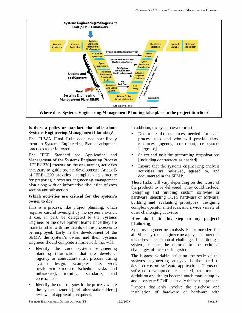
CHAPTER 3.4.2 SYSTEMS ENGINEERING MANAGEMENT PLANNING
SYSTEMS ENGINEERING GUIDEBOOK FOR ITS 12/2/2009 PAGE 54
Where does Systems Engineering Management Planning take place in the project timeline?
Is there a policy or standard that talks about Systems Engineering Management Planning? The FHWA Final Rule does not specifically mention Systems Engineering Plan development practices to be followed. The IEEE Standard for Application and Management of the Systems Engineering Process [IEEE-1220] focuses on the engineering activities necessary to guide project development. Annex B of IEEE-1220 provides a template and structure for preparing a systems engineering management plan along with an informative discussion of each section and subsection. Which activities are critical for the system’s owner to do? This is a process, like project planning, which requires careful oversight by the system’s owner. It can, in part, be delegated to the Systems Engineer or the development teams since they are more familiar with the details of the processes to be employed. Early in the development of the SEMP, the system’s owner and their Systems Engineer should complete a framework that will: Identify the core systems engineering
planning information that the developer [agency or contractor] must prepare during system design. Examples are: work breakdown structure [schedule tasks and milestones], training, standards, and constraints.
Identify the control gates in the process where the system owner’s [and other stakeholder’s] review and approval is required.
In addition, the system owner must: Determine the resources needed for each
process task and who will provide those resources [agency, consultant, or system integrator].
Select and task the performing organizations [including contractors, as needed].
Ensure that the systems engineering analysis activities are reviewed, agreed to, and documented in the SEMP.
These tasks will vary depending on the nature of the products to be delivered. They could include: Designing and building custom software or hardware, selecting COTS hardware or software, building and evaluating prototypes, designing complex operator interfaces, and a wide variety of other challenging activities. How do I fit this step to my project? [Tailoring] Systems engineering analysis is not one-size fits all. Since systems engineering analysis is intended to address the technical challenges in building a system, it must be tailored to the technical challenges of the specific system. The biggest variable affecting the scale of the systems engineering analysis is the need to develop custom software applications. If custom software development is needed, requirements definition and design become much more complex and a separate SEMP is usually the best approach. Projects that only involve the purchase and installation of hardware or hardware with

CHAPTER 3.4.2 SYSTEMS ENGINEERING MANAGEMENT PLANNING
SYSTEMS ENGINEERING GUIDEBOOK FOR ITS 12/2/2009 PAGE 55
embedded COTS software applications do not require the same depth of requirements analysis and design. Of course, these projects may require serious trade studies on such issues as product selection, site selection, or communications alternatives. The SEMP for such projects may be quite short and can be combined into the Project Plan for efficiency. Another factor is the degree to which the system owner is comfortable with the technologies involved. If the system owner is unsure or there is a perceived risk, then added attention to the preparation of a SEMP is advised. The final factor is the degree to which the System Engineer and Development Teams have their own well-developed processes, such as requirements management, configuration management, or software development. Where the agency does not have any of these processes in place, it is recommended that they identify and select experienced development firms with established processes. In such cases, the SEMP should reference these processes [tailored appropriately] and only deal in detail with the unique processes needed for the project. What should I track to reduce project risk and to get what is expected? [Technical Measures, Metrics] On the technical side: Technical performance measures [e.g.
response times and capacity.] must be defined in the requirements and then shown to be met [simulation and modeling] by the design
A complete end-to-end trace from user needs and the Concept of Operations to the delivered products
On the project management side: The completeness of the documents produced
by each task and their correlation with the various technical reviews
Prompt resolution and incorporation of stakeholder comments to the documents and the technical reviews
Compliance with the systems engineering analysis processes documented in the SEMP
Checklist: Are all the bases covered? Are all needed process steps, along with their
process, inputs, and outputs identified? Are all known requirements and constraints
on the design [specific hardware and COTS software products] incorporated into the process steps?
Are all necessary technical reviews identified and planned?
For each process task, are the performing organization and other needed resources, identified and available?
Is the required content of each deliverable document clear to the performing organization?
Is the delivery of custom software and supporting documentation clearly specified?
Is the Configuration Management Plan clear about who needs to approve changes to any baseline?
Has a selection committee and the selection criteria been established to support each procurement activity?
Do the design, integration, and verification plans support the deployment goals for the system?
Are the project risk areas adequately addressed?
Are there any recommendations that can help? An adequate level of commitment to project management is essential for ensuring the effective delivery
and operation of ITS projects. Industry process standards for information technology systems point to the use of the SEMP as that engineering plan for technical control. Although, not specifically called out in federal regulation, the SEMP is considered a critical means of addressing accountability for ensuring both efficient and effective results of any systems engineering. To the extent possible, the SEMP should plan for all disciplines [development teams] required during the project life cycle and involve the disciplines in each of the technical tasks. At a minimum, this means that some hardware and software design engineers should be involved during the first tasks of the project, including: elicitation of user needs, preparation of a Concept of Operations, and requirements analysis. Likewise, some of the systems engineers, who developed the requirements, should stay involved in the project through the design, production, integration, verification, and deployment tasks. This will integrate the processes and help ensure that the final system meets the original project goals.

Section 3.4.3 Concept of Operations
SYSTEMS ENGINEERING GUIDEBOOK FOR ITS 12/2/2009 PAGE 56
3.4.3 Concept of Operations
OBJECTIVE: The Concept of Operations documents the total environment and use of the system to be developed in a non-technical and easy-to-
understand manner presents this information from multiple viewpoints provides a bridge from the problem space and stakeholder needs to the system level requirements
DESCRIPTION: The Concept of Operations document results from a stakeholder view of the operations of the system being developed. This document will present each of the multiple views of the system corresponding to the various stakeholders. These stakeholders include operators, users, owners, developers, maintenance, and management. This document can be easily reviewed by the stakeholders to get their agreement on the system description. It also provides the basis for user requirements.
CONTEXT OF PROCESS:
CONCEPT OF OPERATIONS PROCESS

Section 3.4.3 Concept of Operations
SYSTEMS ENGINEERING GUIDEBOOK FOR ITS 12/2/2009 PAGE 57
Inputs: Project goals and objectives determine how the system will be used. Recommended system concept describes the concept selected with the best benefit for the cost. This concept will be the basis for the concept of operations. Regional ITS architecture will provide the roles and responsibilities of the primary stakeholders and the systems they operate, which may suggest features for the project concept of operations. Needs Assessment includes the list of collected needs, their sources, and documentation of the rationale for the selection of the key needs and any constraints that exist that may limit possible solutions to the needs. The development of the Concept of Operations starts with these needs and constraints. Feasibility assessment or FSR defines and analyzes the conceptual system and, in the process, provides operational information.
Control: The Project Plan describes the project and the SEMP describes the systems engineering effort needed for development. They both guide what may be developed.
Enablers: Elicitation supports continual stakeholder input and review. This is essential to developing a system that meets their needs. Technical reviews support continuing communications with the stakeholders, which are essential to developing a concept that reflects their needs within the stakeholders organization and operations. Trade studies are used for the selection and documented rational of the optimum concept. Stakeholder involvement is essential to ensure that the system will operate in a way that is useful to them. Traceability of scenarios to user needs, requirements, design, implementation, and verification
Outputs: Concept of operations describes the operation of the system being developed from the various stakeholder viewpoints. It documents the user’s requirements for ultimate system operations. The users and other stakeholders can review the document and provide feedback and validate these key going-in assumptions.
Process Activities: Define project vision, goals, and objectives Revisit the vision, goals, and objectives identified in Concept Exploration & Benefits Analysis [Ch. 3.3.2]. Expand and elaborate on them to capture multiple viewpoints. Explore project concepts Revisit the alternative concepts identified during Concept Exploration & Benefits Analysis [Ch. 3.3.2]. The goal is to glean just enough of a physical description of the system from the high-level system architecture to write the Concept of Operations. Perform additional trade studies as needed. Develop operational scenarios Operational scenarios describe how the system will be operated under various conditions. For example, incident management scenarios will include normal monitoring, the sequence of events following an incident, and response to failure [e.g., sensors or communications]. These scenarios will describe the activities from the viewpoint of each of the participants. Some techniques for describing the scenarios are flow diagrams and use cases, which are part of the unified modeling language used for software development. Develop and document the concept of operations The Concept of Operations is a document that records these findings and system characteristics from each of the multiple viewpoints of the various stakeholders. It is written in a language that they each understand. This document includes such information as vision, goals and objectives, operational philosophies, operational environment, support environment, operational scenarios, operational system characteristics, system constraints & limitations, institutional issues, external interfaces, stakeholder functions, roles & responsibilities, and capabilities.
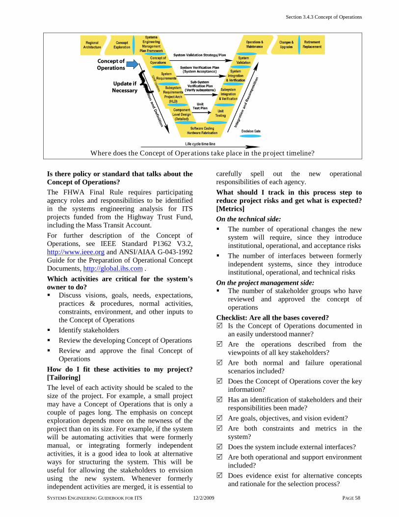
Section 3.4.3 Concept of Operations
SYSTEMS ENGINEERING GUIDEBOOK FOR ITS 12/2/2009 PAGE 58
Where does the Concept of Operations take place in the project timeline?
Is there policy or standard that talks about the Concept of Operations? The FHWA Final Rule requires participating agency roles and responsibilities to be identified in the systems engineering analysis for ITS projects funded from the Highway Trust Fund, including the Mass Transit Account. For further description of the Concept of Operations, see IEEE Standard P1362 V3.2, http://www.ieee.org and ANSI/AIAA G-043-1992 Guide for the Preparation of Operational Concept Documents, http://global.ihs.com . Which activities are critical for the system’s owner to do? Discuss visions, goals, needs, expectations,
practices & procedures, normal activities, constraints, environment, and other inputs to the Concept of Operations
Identify stakeholders Review the developing Concept of Operations Review and approve the final Concept of
Operations How do I fit these activities to my project? [Tailoring] The level of each activity should be scaled to the size of the project. For example, a small project may have a Concept of Operations that is only a couple of pages long. The emphasis on concept exploration depends more on the newness of the project than on its size. For example, if the system will be automating activities that were formerly manual, or integrating formerly independent activities, it is a good idea to look at alternative ways for structuring the system. This will be useful for allowing the stakeholders to envision using the new system. Whenever formerly independent activities are merged, it is essential to
carefully spell out the new operational responsibilities of each agency. What should I track in this process step to reduce project risks and get what is expected? [Metrics] On the technical side: The number of operational changes the new
system will require, since they introduce institutional, operational, and acceptance risks
The number of interfaces between formerly independent systems, since they introduce institutional, operational, and technical risks
On the project management side: The number of stakeholder groups who have
reviewed and approved the concept of operations
Checklist: Are all the bases covered? Is the Concept of Operations documented in
an easily understood manner? Are the operations described from the
viewpoints of all key stakeholders? Are both normal and failure operational
scenarios included? Does the Concept of Operations cover the key
information? Has an identification of stakeholders and their
responsibilities been made? Are goals, objectives, and vision evident? Are both constraints and metrics in the
system? Does the system include external interfaces? Are both operational and support environment
included? Does evidence exist for alternative concepts
and rationale for the selection process?
CHAPTER 3.4 PROJECT PLANNING AND CONCEPT OF OPERATIONS DEVELOPMENT
SYSTEMS ENGINEERING GUIDEBOOK FOR ITS 12/2/2009 PAGE 59
Does the process include operational scenarios?
Has the Concept of Operations been reviewed and accepted by the stakeholders?
Are there any recommendations that can help? The Concept of Operations has applicability beyond this phase in the development. Since the Concept of Operation
describes how the system is expected to operate in its intended environment, it can be used to support the validation of the system, training, and users & maintenance manuals.
There is a temptation at this point to make assumptions about system design. The Concept of Operations should address what is to be done, but
not how it will be implemented. That will be determined later during design. A closer look at scenarios – scenarios are an important part of the Concept of Operations. They should include, at a minimum: What is to be done? Who will do it? What is communicated? To whom? This could be a flowchart or text. It must be something easily understandable by the stakeholders. A simple way to do this is to write the scenario from the viewpoints of each of the stakeholders involved. Some other techniques that one may see used in concepts of operation are use cases, thread analysis, and flow analysis. Here is a simple example of a text scenario for a transit system from the view of the dispatcher. There will be corresponding scenarios for the driver, maintenance, and the bus yard. Scenario: Bus breakdown Viewpoint: Dispatcher Receive notification of breakdown from the
driver. Locate bus. Request repairs from maintenance
department. Request replacement bus from the bus yard. Confirm actions complete. Notice that this scenario does not specify how these steps will be completed This scenario is short and easy to present to the stakeholders. Their feedback at this point will
prevent re-design later. For example, the maintenance department may say that they always contact the yard when they are called for a breakdown. So the dispatcher does not need to do that. A manager may point out that they need to have the actions logged. These changes are easy to make now. Multiple viewpoints The most important purpose of the Concept of Operation is to get agreement from the stakeholders on: their responsibilities how the system will operate the environment system expectations processes that the system will support This is best accomplished by presenting the information from the viewpoint of each of the stakeholders. Then, they can readily review and respond to it. Be sure that the document addresses the system from the viewpoint of the operator, user, owner, developer, maintenance, and management. It should answer the “five Ws and an H” that reporters are supposed to address in their writing: who, what, when, where, why, and how. The environment in which the system will operate arguably has as much influence on system performance as does the system itself. This includes not only the physical environment, but also the political, procedural, operational, and any other factors which either support or constrain system operation. The following considerations circumscribe the system to be developed and should be addressed in the Concept of Operations: Mission objectives and rationale Operational philosophies Operational system characteristics System constraints and limitations Relevant stakeholders organizations and
policies External interfaces and requirements The system is surrounded by its operational and support environments. The operational environment describes the conditions under which the system will be used. For example, will the operators be doing other tasks while operating the system? The support environment includes such things as maintenance, disposal, facilities, and utilities.

CHAPTER 3.4.3 CONCEPT OF OPERATIONS
SYSTEMS ENGINEERING GUIDEBOOK FOR ITS 12/2/2009 PAGE 60
3.5 System Definition
Figure 3-9 Phase 2 - System Definition Roadmap

CHAPTER 3.5.1 REQUIREMENTS DEVELOPMENT [SYSTEM AND SUB-SYSTEM LEVEL REQUIREMENTS]
SYSTEMS ENGINEERING GUIDEBOOK FOR ITS 12/2/2009 PAGE 61
3.5.1 Requirements Development [System and Sub-system Level Requirements] OBJECTIVE: Requirements are the foundation for building Intelligent Transportation Systems [ITS]. They determine WHAT the system must do and drive the system development. Requirements are used to determine [verify] if the project team built the system correctly. The requirements development process identifies the activities needed to produce a set of complete and verifiable requirements. DESCRIPTION: Requirements development is a set of activities that will produce requirements for the system and sub-systems. The systems engineering standard [EIA 632] defines “requirement” as “something that governs what, how well, and under what conditions a product will achieve a given purpose.” Requirements define the functions, performance, and environment of the system under development to a level that can be built: Does the system do WHAT it is supposed to do? - These are Functional requirements. How well does the system do its functions? - These are Performance requirements. Under what conditions [e.g. environmental, reliability, and availability.], does the system have to work and meet its performance goals? – These are Environmental and Non-Functional requirements. There are other types of enabling requirements that are also needed but often overlooked. They define other aspects of systems development that are needed [but do not show up] as part of the system. Some examples are: development, testing, support, deployment, production, training, and in some cases disposal. Primarily the Functional, Performance, Environmental, and Non-Functional Requirements are contained in the System and Sub-system requirements documents. The enabling requirements may also be in these documents but they mainly show up in the various plans [SEMP and project plan], statements of work for contracted work, and memorandums of understandings among participating stakeholders. CONTEXT OF PROCESS:
REQUIREMENTS DEVELOPMENT PROCESS
Inputs: Concept of Operations documents the user needs, expectations, goals, and objectives. It describes the way the system is intended to operate from the user’s perspective.

CHAPTER 3.5.1 REQUIREMENTS DEVELOPMENT [SYSTEM AND SUB-SYSTEM LEVEL REQUIREMENTS]
SYSTEMS ENGINEERING GUIDEBOOK FOR ITS 12/2/2009 PAGE 62
Regional ITS Architecture defines the regional framework [environment] in which this project must operate. Major external interfaces, high level functional requirements, and stakeholders are identified. Feasibility Study produces the conceptual high-level design and requirements which can be used as a starting point for the project.
Control: Project Plan/SEMP contain various plans, such as the review plans, configuration management plans, and risk plans. [Control the requirements development]. Configuration management [CM] identifies the process to control changes to the requirements and manage the baseline documentation. Risk management is used to monitor, control, and mitigate high risk requirements.
Enablers: Technical reviews are used to identify defects, conflicts, missing, or unnecessary requirements. Then, the requirements review control gate [formal review] is used to approve the final set of requirements. Stakeholder involvement is essential for validating the requirements. Are these the correct requirements? Elicitation enables the discovery and understanding of the needed requirements. A technical trade study is used to analyze and compare alternative requirements and their technical and cost impacts on the system. Traceability of requirements to user needs & requirements, support documentation, and constraining policies [e.g., safety requirements & regional ITS architecture].
Outputs: System and Sub-system Requirements Documents must be complete, verifiable, and validated. After formal review and approval by the system owner and stakeholders, they are put under configuration control. Verification Plan [from the verification process] documents the plan to verify each system requirement.
Processes Activities: Develop requirements The first step is to develop requirements from the stakeholder needs and input products. Once requirements are documented, they are prioritized, de-conflicted, and validated with the stakeholders. Write and document requirements Characteristics of “good” system requirements are: they should be necessary, testable, clear, concise, technology-independent, feasible, and stand-alone. Requirements must be documented in order to establish the base to build upon [called a baseline], and for managing changes to the requirements. Check completeness A complete set of requirements defines all system functions that are needed to satisfy the stakeholder needs with their associated performance, environmental, and other non-functional requirements. Analyze, refine, and decompose requirements This process examines each requirement to see if it meets the characteristics of a good requirement [e.g., clear, unambiguous, and verifiable]. Each requirement will be decomposed into a more refined set of requirements that are allocated to sub-systems, and performance requirements are defined. Newly derived requirements are expected to emerge from this process, which continues until all requirements are defined and analyzed and the final project architecture is defined. Validate requirements Each requirement must be validated to ensure that these are the correct requirements. This will be done through stakeholder walkthroughs and tracing requirements to an associated need. Manage requirements Once the requirements have been accepted and a baseline is established by the stakeholders, changes to the requirements are controlled using a change management process.

CHAPTER 3.5.1 REQUIREMENTS DEVELOPMENT [SYSTEM AND SUB-SYSTEM LEVEL REQUIREMENTS]
SYSTEMS ENGINEERING GUIDEBOOK FOR ITS 12/2/2009 PAGE 63
Where does the Requirements Development take place in the project timeline?
Is there a policy or standard that talks about Requirements? The FHWA Final Rule requires that requirements be developed for ITS projects funded with the Highway Trust Fund, including the Mass Transit Account. The IEEE 1233 Guide for developing system requirements specifications provides a standard for developing requirements. Which activities are critical for the System’s owner to do? Assist in gathering requirements and getting
the correct stakeholders involved Review requirements to make sure they are
complete and address all of the needs Participate in the requirements walkthrough.
Ensure the correct requirements are being developed [validating the requirements]
Gain stakeholder approval and support for the requirements
Track the requirements development activities How do I fit these activities to my project? [Tailoring] In this activity, there are no shortcuts. Requirements development is a critical process for new systems. On small systems, the owner may be able to reduce the number of requirements documents by combining the system and sub-system requirements. What should I track in this process step to reduce project risks and get what is expected? [Metrics] On the technical side: Changes to requirements [high priority, cost,
and risk] lead to increased cost and increased technical risk. The goal is to minimize
changes to requirements after the baseline is established
An incomplete set of requirements leads to increased technical risk and increased cost. The goal is to track the number of requirements that have been fully defined, analyzed, and decomposed
On the project management side: The number of completed requirements
should match the schedule and work plan. The goal is that the completion rate of requirements should match, or exceed the plan prediction
The growth in the number of requirements after the baseline has been established often leads to "scope creep"
Checklist: Are all the bases covered? Were the requirements documented? Was a requirements walkthrough held to
validate the requirements? Was each requirement checked to see that it
met all of the following? - Necessary [trace to a user need] - Concise [minimal] - Feasible [attainable] - Testable [measurable] - Technology Independent [avoid “HOW to”
statements unless they are real constraints on the design of the system]
- Unambiguous [Clear] - Complete [function fully defined]
Was a verification case for each requirement developed? [test, demonstration, analysis, inspection]
CHAPTER 3.5.1 REQUIREMENTS DEVELOPMENT [SYSTEM AND SUB-SYSTEM LEVEL REQUIREMENTS]
SYSTEMS ENGINEERING GUIDEBOOK FOR ITS 12/2/2009 PAGE 64
Was each user need fully addressed by one or more system requirement(s)?
Is the requirement set complete? Have the following types of requirements been defined? - Functional - Performance - Enabling [training, operations &
maintenance support, development, testing, production, deployment, disposal]
- Data - Interface - Environmental - Non-functional [reliability, availability,
safety, and security]. Were attributes [quality factors] assigned to
each requirement [Priority, risk, cost, owner, date, and verification method]? Verification methods could include demonstration, analysis, test, and inspection.
Were the requirements reviewed and approved by the stakeholders and was a baseline [reference point for future decisions] established?
During this process step, were periodic reviews performed? Were the reviews done in accordance with the review plan documented in the SEMP?
Are there any other recommendations that can help?
Requirements development activity Give ample time to this activity. This is an area of high stakeholder involvement. This activity addresses risk early in the
development cycle where the cost impacts are low; instead of later where the cost impacts are high. Do not approve [Baseline] the requirements too early. Give ample time to develop a set of requirements that are complete and well written. Once developed and approved, the requirements baseline will need to be managed using a change control process [See Chapter 3.7.3]. Changes [e.g. additions, changes or deletion of requirements] after the baseline has been established normally will mean a cost and/or schedule change. [Scope creep or loss of functionality]
Tools are essential in managing requirements on large ITS systems with hundreds of requirements. There are a number of tools that can help in the development of requirements. These tools manage the tracing of requirements, requirements attributes, and perform change management for requirements. For an extensive list of tools please see http://www.incose.org . A closer look at attributes, baseline, and completeness of requirements: Attributes are user-defined quality factors assigned to each requirement. Some of the more common attributes used are: Author [Who requested it?] Date [When was it requested?] Owner [Who is responsible for completing
it?] Risk [Low, medium or high] Cost [Low, medium or high] Priority [How important is this requirement?]
These attributes can help track the technical and project performance. Attributes help in sorting and monitoring requirements. Requirements
management tools have features that allow for managing these attributes along with the requirements. Requirements Baseline [reference point] - Has the requirements document been formally approved by the system owner and stakeholders? If so, all future development and project decisions are based on the requirements baseline. New requirements that are added, and existing ones that are changed or deleted, would be controlled closely using a change management process identified in the Configuration Management Plan. Once changes have been approved by the stakeholders, a new baseline would be established. Completeness of requirements ensures that all aspects of user needs are completely defined by a set of requirements. There is a trap in looking at functions as “stove-pipes” in isolation of other functions. This may cause problems when the functions are integrated together. One way to mitigate this is to make sure that all functions are thoroughly understood and that the analysis of requirements through decomposition integrates all required functions.
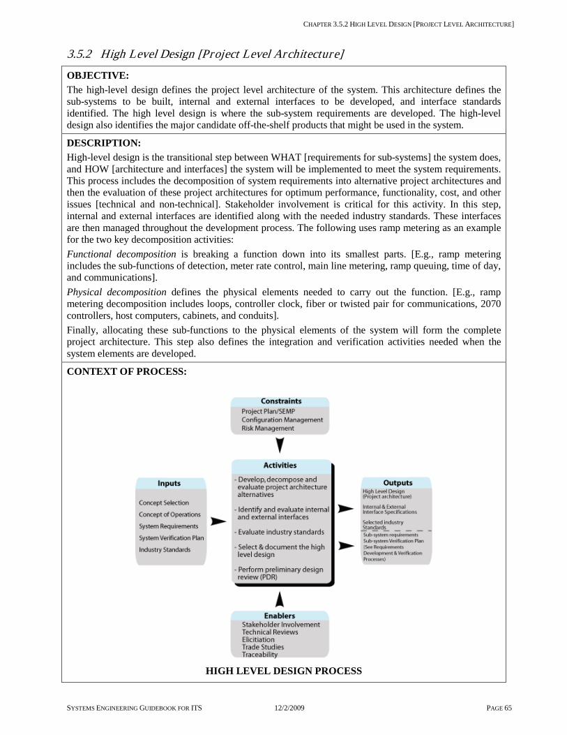
CHAPTER 3.5.2 HIGH LEVEL DESIGN [PROJECT LEVEL ARCHITECTURE]
SYSTEMS ENGINEERING GUIDEBOOK FOR ITS 12/2/2009 PAGE 65
3.5.2 High Level Design [Project Level Architecture]
OBJECTIVE: The high-level design defines the project level architecture of the system. This architecture defines the sub-systems to be built, internal and external interfaces to be developed, and interface standards identified. The high level design is where the sub-system requirements are developed. The high-level design also identifies the major candidate off-the-shelf products that might be used in the system.
DESCRIPTION: High-level design is the transitional step between WHAT [requirements for sub-systems] the system does, and HOW [architecture and interfaces] the system will be implemented to meet the system requirements. This process includes the decomposition of system requirements into alternative project architectures and then the evaluation of these project architectures for optimum performance, functionality, cost, and other issues [technical and non-technical]. Stakeholder involvement is critical for this activity. In this step, internal and external interfaces are identified along with the needed industry standards. These interfaces are then managed throughout the development process. The following uses ramp metering as an example for the two key decomposition activities: Functional decomposition is breaking a function down into its smallest parts. [E.g., ramp metering includes the sub-functions of detection, meter rate control, main line metering, ramp queuing, time of day, and communications]. Physical decomposition defines the physical elements needed to carry out the function. [E.g., ramp metering decomposition includes loops, controller clock, fiber or twisted pair for communications, 2070 controllers, host computers, cabinets, and conduits]. Finally, allocating these sub-functions to the physical elements of the system will form the complete project architecture. This step also defines the integration and verification activities needed when the system elements are developed.
CONTEXT OF PROCESS:
HIGH LEVEL DESIGN PROCESS

CHAPTER 3.5.2 HIGH LEVEL DESIGN [PROJECT LEVEL ARCHITECTURE]
SYSTEMS ENGINEERING GUIDEBOOK FOR ITS 12/2/2009 PAGE 66
Inputs: System Requirements are used as the primary source for the project level architecture. Concept of Operations provides user requirements and context to the sub-systems requirements. System Verification Plan will provide context information for sub-system verification [what the sub-system needs to do to meet the system verification]. This augments the system level requirements.
Control: Project Plan / Systems Engineering Management Plan [SEMP] defines the process for developing the design. Configuration Management Plan defines the process for managing changes to requirements. Risk management monitors, controls, and mitigates high risk factors of the High Level Design, architectures, requirements, and technology.
Enablers: Elicitation supports this process, which is essential to developing a system that meets stakeholder needs. Technical reviews support continuing communications with the stakeholders, which are essential to developing a concept that reflects their needs within the stakeholders organization and operations. Trade studies are used to analyze design alternatives and to select among them. Stakeholder involvement is needed to validate the sub-system requirements and architecture. Traceability for architecture elements and sub-system requirements to system level requirements and other supporting documents, such as standards, to ensure compliance and completeness.
Outputs: High Level Design [project architecture] is documented, and controlled moving forward into detailed design. Internal and external interface specifications that will need to be managed. Selected industry standards that are recommended for the High Level Design. Sub-system Requirements and Sub-system Verification Plans from the requirements/verification process
Process Activities: Develop, decompose, and evaluate project architecture/High Level Design [HLD] alternatives Systems engineers will first evaluate several candidate architectures/HLD’s that appear to meet the requirements. Using analytical tools and methods, each alternative is decomposed into simple functions that are then allocated to sub-systems where they are evaluated to see if this HLD meets the system requirements [functionality and performance]. This process repeats until each HLD is complete. Identify and evaluate internal and external interfaces Interfaces should be identified as early as possible and then managed throughout the development process. Interfaces will define the boundaries of the system [external from requirements] and sub-systems [internal from HLD]. They will be natural points for integration. Evaluate industry standards Use industry standards wherever possible. ITS systems will evolve over time and novel interfaces will be much more difficult to manage and change. Standard interfaces will tend to be more flexible. Since it is a standard, it will be easier to find products that will interface if needed. Select and document the High Level Design Trade studies are used select architectures. If there is a clear HLD that “wins” over the other candidates, it should then be presented to the system’s owner and stakeholders for their concurrence. Perform the preliminary design review This consists of a review of the draft High Level Design document and of a design review presented to the system’s owner and stakeholders. The team will revise the document based on stakeholder comments and submit the final High Level Design document. Since this is the first time that sub-systems are defined, the team will develop sub-system test plans and will update the SEMP as necessary.

CHAPTER 3.5.2 HIGH LEVEL DESIGN [PROJECT LEVEL ARCHITECTURE]
SYSTEMS ENGINEERING GUIDEBOOK FOR ITS 12/2/2009 PAGE 67
Where does the High Level Design take place in the project timeline?
Is there a policy or standard that talks about High Level Design? The FHWA Final Rule requires requirements to be developed for ITS projects funded with the Highway Trust Fund, including the Mass Transit Account. It also requires the analysis of alternative system configurations to meet requirements. The IEEE 1233 Guide for developing system requirements specifications provides a standard for developing requirements. Which activities are critical for the system’s owner to do? Negotiate interface agreements if the system
has interfaces to other legacy systems Review High Level Design alternatives Participate in and review the alternative
selection process, especially in determining the relative importance of various selection criteria
Participate in the high level design review and insure the right stakeholders are in attendance
Review and approve the High Level Design document
How do I fit these activities to my project? [Tailoring] The level of each activity should be appropriately scaled to the size and budget of the project. For example, a small project may have an analysis of alternatives that is only a page or two long, based upon qualitative comparisons. Constraining the number of sub-systems will also reduce the effort here and in the subsequent steps, such as integration and verification.
What should I track in this process step to reduce project risks, and get what is expected? [Metrics] On the technical side: The tradeoffs of functionality, performance,
and technology for alternative High Level Design.
The interfaces of the system and especially the unique and non-standard interfaces
The trend in design toward unproven technologies or equipment increases risks
The trend toward a design requiring higher development or O&M costs increases risks
On the project management side: The levels of decomposition will drive the
integration and verification effort adding integration costs and schedule time.
The interfaces to external systems will require agreements which need to be developed and managed. This tends to increase schedule due to institutional issues of approvals and commitments
The number of identified alternatives that have been fully analyzed can be a risk of increased cost
The number of completed sub-system designs included
Checklist: Are all the bases covered? Were alternative project architectures/high
level designs considered? Is there documented rationale for the selected
project architecture/high level design? Are all interfaces identified and documented? Have industry standards been identified for
the high level design? Is the design clearly documented?
CHAPTER 3.5.2 HIGH LEVEL DESIGN [PROJECT LEVEL ARCHITECTURE]
SYSTEMS ENGINEERING GUIDEBOOK FOR ITS 12/2/2009 PAGE 68
Is the high level design traceable to the system requirements?
Do any of the requirements need to be changed based on the high level design development effort?
Have the integration, verification, and deployment plans been updated in the SEMP?
Are there any other recommendations that can help?
Tools and techniques are available to support high level design. These
tools include functional decomposition tools, modeling tools, and management tools for tracking changes to the high level design. As a general rule, do not specify any part of the design unless that design decision has been justified during the alternatives studies. Sometimes, there is a tendency to insert design solutions to early in the process. For example, specifying workstation models, speed, memory to early may unduly constrain the implementation and lead to higher development costs or obsolescence before deployment of the system. A closer look at high level design alternative project architectures and architectural views. Sub-systems defined in the High Level Design The High Level Design process defines the division of the system into sub-systems. Sub-systems, and the way they relate to each other, become the project architecture. Sub-systems may be needed for a the following reasons: 1] The development or procurement of system elements separately. For instance, if the system includes a wide area network [WAN] to connect multiple sites, that WAN may be a sub-system with a common interface [say the input to a router] to other sub-systems. 2] The deployment of system elements to different locations, or in different configurations, to multiple locations. 3] Dividing a complex system into simpler elements, each of which has an independent set of functions. 4] The allocation of functions to sub-systems. Sometimes it will be necessary to further decompose a function and allocate its sub-functions to individual sub-systems. Hardware defined in the High Level Design Hardware definition is somewhat synonymous with a physical architecture description [although there is also a software aspect to the architecture
that will be covered next]. Each of the architecture components [which may or may not be considered sub-systems] must be defined in terms of its hardware. The definition may be generic [e.g. a workstation, a server, or traffic signal controller] or may be specific [by manufacturer and model number] depending on the results of the alternatives studies previously done. Software defined in the High Level Design Usually, each sub-system would have a separately identified software component. A sub-system may have several if it contains multiple processors. The software component should be defined both in terms of its custom developed parts [the application] as well as its COTS parts, such as the operating system, database software, or communications software. Here again, these software components should be defined generically, unless an alternative study has determined that a specific product is necessary. It is for the custom designed software application that tracing of functional and performance requirements are most important. Other aspects of the high level software design may be dependent on the design methodology used. For instance, if object oriented methods are to be used, the high level design would identify major objects of the system. Operator interface defined in the High Level Design The details of the operator interface design are a critical part of the requirements of the system. It is also a part of the design that requires extensive input from the eventual users and operators of the system. Of course, if the operator interface is just an on/off switch, that is not much of a design problem. But, here we are talking about a workstation interface which can be surprisingly complex. The operator interface design must describe in detail everything displayed to the operator and all actions the operator can take, via the workstation. If the display contains a map, then all the contents of that map [e.g. roads, icons for loop detectors, signals, or message signs] must be defined both in terms of what it looks like, as well as when it is displayed. For instance, maps are generally divided into layers of similar information and each layer can be turned on or off by the operator. Similarly, all actions by the operator to enter data or to cause things to happen [like displaying a message on a sign] must be defined. Both display and entry should be designed in ways that limit operator error; from looking at the wrong data to entering a wrong value or command.

CHAPTER 3.5.2 HIGH LEVEL DESIGN [PROJECT LEVEL ARCHITECTURE]
SYSTEMS ENGINEERING GUIDEBOOK FOR ITS 12/2/2009 PAGE 69
The project management and systems engineering team for the project must support decisions on the appropriate level of engineering and operational talent to be applied to the operator interface design. It is not a task to be left to the software programmers. Alternative project level architectures Based on the previous work [e.g., concept exploration, user needs, concept of operations, project plan, SEMP, and system requirements] this phase develops the project architecture of high level design of the planned system. The system requirements should be design independent. There is, usually, by this time in the project life cycle, some expectation of a functional and physical architecture brought forward from the concept exploration phase. The alternatives may be complete for the entire system or perhaps alternatives for just a part of the system. It is not uncommon that various alternatives can be combined into a large number of different configurations. Alternatives should be defined before the allocation is done. There may be alternative allocation of functions that should be considered. For example, loop data processing may be done at the roadside or centrally. Trade studies are used to evaluate the alternatives relative to the requirements and determine which are compliant. They will then compare the compliant alternatives in terms of cost, performance, and goals & objectives. What to do with project architectures that fall short?
Even project architectures that fall short of meeting all requirements may provide useful information. Sometimes an otherwise promising HLD may fall short of some of the
requirements, especially ambitious performance requirements. If the HLD has some useful features then it may be carried forward as an alternate solution. Certainly the degree to which such a design does not meet user needs should be an important factor. Alternative fully-compliant designs should be documented for future reference. In fact, the entire evaluation process,
including the alternatives considered and not considered, and the rationale for the selection and rejection, should be documented so stakeholders can review them. There are many views that are very useful and should be used appropriately. The following are examples of different views that can be used. In the description at the beginning of this chapter, we focused on two views in the example, the functional view and the physical view. These are the most common ways that systems are described because they are easy to understand. Operational views [behavioral, dynamic] Information views [data, data flow] Network views [distributed, centralized] Activity view [functional] Physical view [hardware, software] Operational view [behavioral, dynamic], describes how the system will react when it is stimulated. This is a dynamic modeling of the system that is important when real-time operation needs to be carefully analyzed. Information views [data, data flow], are used in data intensive systems where the data needs to be modeled in order to determine how the optimum system architecture will handle the information. Examples: how much communications bandwidth will be
needed how the data is to be stored and accessed Network views [distributed, centralized] are used when analyzing the interactions between various system elements on complex networks. This aids in understanding the addressing schema, and in analyzing protocol efficiencies for the network. Activity view [functional], are the functions that are to be carried out by the system. [For examples, see the description at the beginning of this chapter.] Physical view is the equipment that is used in the system. [For examples, see the description at the beginning of this chapter]
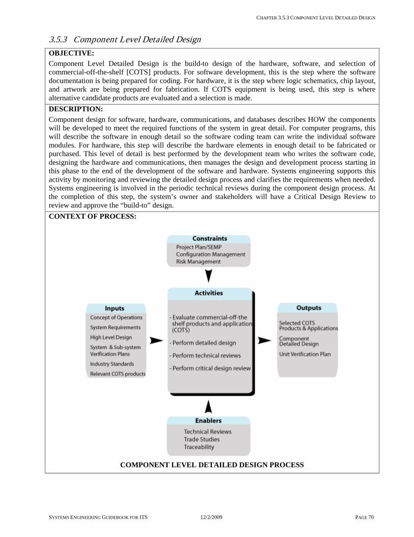
CHAPTER 3.5.3 COMPONENT LEVEL DETAILED DESIGN
SYSTEMS ENGINEERING GUIDEBOOK FOR ITS 12/2/2009 PAGE 70
3.5.3 Component Level Detailed Design OBJECTIVE: Component Level Detailed Design is the build-to design of the hardware, software, and selection of commercial-off-the-shelf [COTS] products. For software development, this is the step where the software documentation is being prepared for coding. For hardware, it is the step where logic schematics, chip layout, and artwork are being prepared for fabrication. If COTS equipment is being used, this step is where alternative candidate products are evaluated and a selection is made. DESCRIPTION: Component design for software, hardware, communications, and databases describes HOW the components will be developed to meet the required functions of the system in great detail. For computer programs, this will describe the software in enough detail so the software coding team can write the individual software modules. For hardware, this step will describe the hardware elements in enough detail to be fabricated or purchased. This level of detail is best performed by the development team who writes the software code, designing the hardware and communications, then manages the design and development process starting in this phase to the end of the development of the software and hardware. Systems engineering supports this activity by monitoring and reviewing the detailed design process and clarifies the requirements when needed. Systems engineering is involved in the periodic technical reviews during the component design process. At the completion of this step, the system’s owner and stakeholders will have a Critical Design Review to review and approve the “build-to” design. CONTEXT OF PROCESS:
COMPONENT LEVEL DETAILED DESIGN PROCESS
CHAPTER 3.5.3 COMPONENT LEVEL DETAILED DESIGN
SYSTEMS ENGINEERING GUIDEBOOK FOR ITS 12/2/2009 PAGE 71
Inputs: Concept of Operations documents the users’ needs and expectations, and provides a description of the way the system is intended to work. System Requirements provide the designer with the overall requirements of the system. Each of the system requirements should be traceable to a sub-system element. High Level Design [Project Architecture] identifies interfaces and sub-system performance requirements. Sub-system Requirements that each designed component should trace to. System and Sub-system Verification Plans provide added information on how the system and sub-system is to be verified. This will assist the designer in designing the components and developing the component verification procedures. COTS products relevant to the project that will be candidates for evaluation and selection for the project. Control: Project Plan/ Systems Engineering Management Plan [SEMP] defines the plan for how the detailed design work will be carried out. Progress of the design work activities should be monitored against this plan. Configuration management [CM] process should have been defined by the development team and approved by the system’s owner. At this step Developmental Configuration Management is used. The Developmental CM must fit into the systems owner CM plan. Risk management is used to monitor, control and mitigate design risks [e.g. technology and/or constraints]. Enablers: Trade studies are used to analyze and compare alternative COTS products, detailed design alternatives and their associated impacts on the system. Technical reviews are used to identify defects, conflicts, and missing detailed design requirements to ensure that the component design is addressing all of the sub-system requirements and is fit for the intended purpose. Traceability of detailed design elements to the high level design elements to ensure completeness Outputs: Selected COTS products and applications are the results of the evaluation of COTS products. Ideally this is done as late as possible in the timeline to provide the latest technologies at the best price. Sometimes, however, this may have to be done earlier because of legacy systems or internal standards. Approved Component Level Detailed Design is now ready to move forward to implementation. Unit Verification Plan is used to verify that the components work as designed. Process Activities: Evaluate commercial off-the-shelf products and applications [COTS] The stakeholders must be involved in the review of any gaps between the requirements and the COTS product specification. If there is a gap then the stakeholders should decide whether to use the COTS product with a deviation from the requirements, modify the product, or develop a custom application or product. Detailed Design This process is performed by the development team, who will be generating the application software and integrating the hardware, databases, and communications with these applications. The development team will use a variety of techniques and tools based on the development team’s approach to development, such as coding languages, methodologies, and design tools. Perform technical reviews [performed in accordance with the SEMP] For design status: evaluation of the candidate solutions or COTS products, technical reviews should be held on a periodic basis to review the progress of the design or selection of COTS products. Perform critical design review [CDR] [performed in accordance with the SEMP] At the completion of the detailed design stage, a final “build to” review is held with the Stakeholders. The purpose is for the development team to get final approval of the design prior to starting the implementation of the solution. Component design through software development to unit test is the domain of the software, hardware, and database specialist of the development team. The systems engineer needs to be able to translate user requirements in the language of these disciplines. For example, if software engineering is using UML methodology, the systems engineer needs to interface between the user needs, systems requirements, and the software engineer to ensure that the design accurately reflects the intended purpose.

CHAPTER 3.5.3 COMPONENT LEVEL DETAILED DESIGN
SYSTEMS ENGINEERING GUIDEBOOK FOR ITS 12/2/2009 PAGE 72
Where does the Component Level Detailed Design take place in the project timeline?
Is there a policy or standard that talks about Component Level Detailed Design? The FHWA Final Rule does not specifically mention component level detailed design practices to be followed. For software, IEEE/ISO 12207 Software Life cycle process provides specific process guidance. Which activities are critical for the system’s owner to do? Participate in the technical reviews Participate in the evaluation of COTS
products Participate in the critical design review Approve the detailed design when completed Gain stakeholder support for the design How do I fit these activities to my project? [Tailoring] This activity is driven by the amount of custom development needed for the project. The more customized the development, the more effort there is at this step. For small systems that contain nearly all COTS products, the primary activity is the evaluation of these products. What should I track in this process step to reduce project risks and get what is expected? [Metrics] On the technical side: Changes to requirements [High Priority, Cost,
and Risk] due to detailed design activities. Changes lead to increased cost and increased technical risk. The goal is to minimize changes to requirements
Incomplete design leads to increased technical risk and increased cost. The goal is to review and track the number of requirements that have been completely designed
On the project management side: Number of completed designed components
per schedule and development plan. The goal is that completion rate of designed components should match or exceed the plan prediction
Checklist: Are all the bases covered? Did each component have a technical review? Did each component design trace to a sub-
system requirement? Were all sub-system requirements satisfied by
the component design activity? Was a verification plan for each component
defined? Was each component design checked for
performance? Was the component design documentation
complete, up to date, and accurate? Was a critical design review conducted? Was an alternatives analysis done on the
COTS products used in the system? Have all system and sub-system requirements
been updated at the time of the critical design review?
Are there any other recommendations that can help? It is recommended that the development team who will be doing the software development also perform this component design activity. This continuity between the component design and development is critical.
Be sure that the development team has documented processes for developing software and hardware, and that they can share this
information with the team. Some development

Section 3.5 System Definition
SYSTEMS ENGINEERING GUIDEBOOK FOR ITS 12/2/2009 PAGE 73
teams will be reluctant to share this information for fear of revealing this information to their competition. If so, it may require that a non-disclosure agreement be in place. But it is important to review the development processes and have it as part of the Systems Engineering Management Plan. Component design tools are essential for component level detailed design and there are many on the market. Each development team will have their favorite set of tools. These tools will be driven by the vendor of the tool, and the process that the development follows. This is especially true for software development.
If this is a custom development, request all tools at the completion of development. This will ensure that the system can be maintained and upgraded with or without the
current development team. The tools that are used in the component design activity need to be carefully documented. If the project paid for these tools they need to be transferred to the system owner with all modifications, upgrades, and instructions on how they were used during the design activity. That way the development environment can be replicated for future modifications.
A closer look at software component design and development - Software design is unique relative to other disciplines, such as hardware or mechanical detailed designs. At the component level, it is tightly linked to the actual coding and implementation phase and there is a higher degree of interaction between the two phases of work. The software process parallels the systems engineering process to a high degree as illustrated below. The team’s development process should address each of the steps below. During the software design, the developer will use the system level documentation, such as the system concept of operations and system and sub-system level requirements, and revisit these from a software point of view. This is an important process if the software development team has not been involved with the system level concept of operations, or system level or sub-system requirements. In the software development environment, prototyping and spiral development methods are important tools for defining requirements. For example, prototyping graphical user interfaces for workstation will allow the stakeholder to discover features and functions that they will like or dislike before software coding. This, I KNOW IT WHEN I SEE IT [IKIWISI], is a powerful tool for software developers [see illustration below].
Figure 3-10 Spiral Software Development in Context with the Vee

CHAPTER 3.5.3 COMPONENT LEVEL DETAILED DESIGN
SYSTEMS ENGINEERING GUIDEBOOK FOR ITS 12/2/2009 PAGE 74
3.6 System Development and Implementation
Figure 3-11 Phase 3 - System Development and Implementation Roadmap

CHAPTER 3.6.1 HARDWARE/SOFTWARE DEVELOPMENT AND UNIT TEST
SYSTEMS ENGINEERING GUIDEBOOK FOR ITS 12/2/2009 PAGE 75
3.6.1 Hardware/Software Development and Unit Test OBJECTIVE This step in the process develops [builds or constructs] the hardware and software for the system that matches the requirements and component level detailed design documentation. This step is primarily the responsibility of the development team, who fabricates the hardware and writes the software programs. The systems engineering activities includes the support and review of the development effort on behalf of the system’s owner. If multiple developments for the same system are underway, the systems engineering activity includes the monitoring and coordination of these developments to ensure these projects integrate together with a minimum of effort. DESCRIPTION: The systems engineering activities include the monitoring and coordination of the hardware & software development activities. The implementation is primarily the responsibility of the implementation team, whether it is in-house or by a contracted development firm. Monitoring is accomplished by a preplanned series of reviews coordinated with the development team. This is performed by the systems engineering staff of the agency or a contracted system manager. It is essential to review the technical progress and provide technical guidance on the implementation of requirements. These reviews provide early warning that requirements are deficient, or they are not being met by the implementation. In such cases deviations or waivers may be needed or the re-evaluation of the requirement may be necessary. Also, these reviews will be needed when coordinating among concurrent developments for the same project, depending on the development strategy. CONTEXT OF PROCESS
HARDWARE/SOFTWARE DEVELOPMENT PROCESS

CHAPTER 3.6.1 HARDWARE/SOFTWARE DEVELOPMENT AND UNIT TEST
SYSTEMS ENGINEERING GUIDEBOOK FOR ITS 12/2/2009 PAGE 76
Inputs Component Level Detailed Design is the “build-to” documentation. The coding and fabrication team develop their products based on this documentation. Commercial-off-the-shelf [COTS] products are procured for the project. The intent is to wait until the last possible opportunity to procure technology to get the latest and most cost effective products. System and Sub-system Verification Plans are used to assist the development team to fully understand the design and requirements they are building to. Control Project Plan/Systems Engineering Management Plan [SEMP] will have the software/hardware development plan used as a roadmap to carry out the software and hardware development. Configuration Management Plan identifies the needed products from the development and manages changes during this step. Risk management identifies, monitors, and controls hardware/software development risks. Enablers: Technical reviews are used for monitoring the project management and technical progress of the development. When multiple concurrent developments are being performed, the technical reviews can be used as coordination meetings to keep projects synchronized with each other. Traceability of implementation elements to the detailed design ensures completeness Outputs: Developed hardware and software are the units or products that have been developed for the intended system. These are units of software and hardware that are ready for integration into larger more complex functions of the target system. Support products, such as user training materials, maintenance manuals plus development and other support tools. Unit Verification Procedures are the step-by-step instructions used to verify that the units match the design. Process Activities: Support, monitor, and review development During the development phase, technical reviews should be held according to the technical review plan developed by the development team. These reviews assess the progress and technical correctness of the implementation of the design. Develop system product This is where the actual software code is developed and the hardware is fabricated for the system. In addition to these, support products are developed, such as users manuals, training products, and maintenance manuals initially developed. As integration and verification proceeds, these products are updated as needed. Final delivery should follow the delivery of sub-systems and the final system. Coordinate concurrent development activities When multiple developments are being performed concurrently, based on the selected development strategy, these meetings should be coordination meetings between the developments to reduce the risk due to any integration between them. This should include schedule, functional, and interface risks. Procure COTS products COTS products should be procured at this time but only if needed in this phase. If the implementation phase is planned to last several months or years, procure only those items which e needed immediately, and push the procurement of this technology to the last possible minute. When doing so, account for lead times of the procurements. The specific domain discipline e.g., software, hardware, database engineering, is expected to: perform unit test document the development environment Perform their own developmental configuration management to the level needed to transfer the
complete design package to the agency [if contracted for].
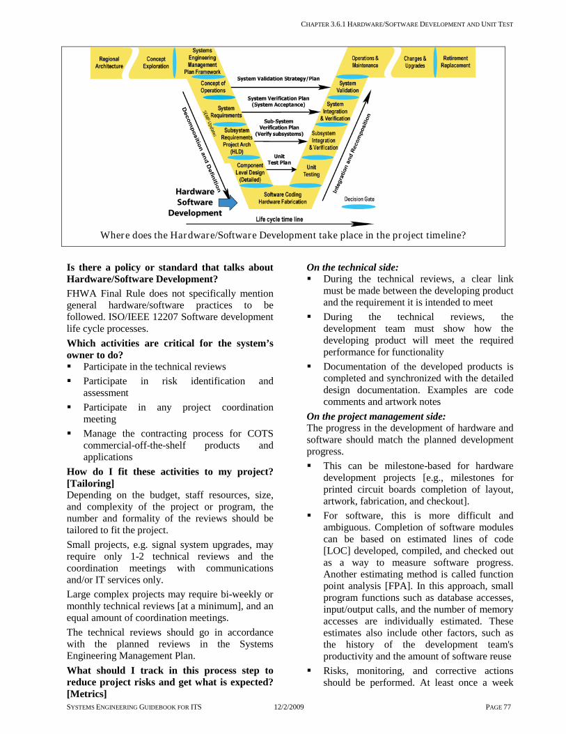
CHAPTER 3.6.1 HARDWARE/SOFTWARE DEVELOPMENT AND UNIT TEST
SYSTEMS ENGINEERING GUIDEBOOK FOR ITS 12/2/2009 PAGE 77
Where does the Hardware/Software Development take place in the project timeline?
Is there a policy or standard that talks about Hardware/Software Development? FHWA Final Rule does not specifically mention general hardware/software practices to be followed. ISO/IEEE 12207 Software development life cycle processes. Which activities are critical for the system’s owner to do? Participate in the technical reviews Participate in risk identification and
assessment Participate in any project coordination
meeting Manage the contracting process for COTS
commercial-off-the-shelf products and applications
How do I fit these activities to my project? [Tailoring] Depending on the budget, staff resources, size, and complexity of the project or program, the number and formality of the reviews should be tailored to fit the project. Small projects, e.g. signal system upgrades, may require only 1-2 technical reviews and the coordination meetings with communications and/or IT services only. Large complex projects may require bi-weekly or monthly technical reviews [at a minimum], and an equal amount of coordination meetings. The technical reviews should go in accordance with the planned reviews in the Systems Engineering Management Plan. What should I track in this process step to reduce project risks and get what is expected? [Metrics]
On the technical side: During the technical reviews, a clear link
must be made between the developing product and the requirement it is intended to meet
During the technical reviews, the development team must show how the developing product will meet the required performance for functionality
Documentation of the developed products is completed and synchronized with the detailed design documentation. Examples are code comments and artwork notes
On the project management side: The progress in the development of hardware and software should match the planned development progress. This can be milestone-based for hardware
development projects [e.g., milestones for printed circuit boards completion of layout, artwork, fabrication, and checkout].
For software, this is more difficult and ambiguous. Completion of software modules can be based on estimated lines of code [LOC] developed, compiled, and checked out as a way to measure software progress. Another estimating method is called function point analysis [FPA]. In this approach, small program functions such as database accesses, input/output calls, and the number of memory accesses are individually estimated. These estimates also include other factors, such as the history of the development team's productivity and the amount of software reuse
Risks, monitoring, and corrective actions should be performed. At least once a week
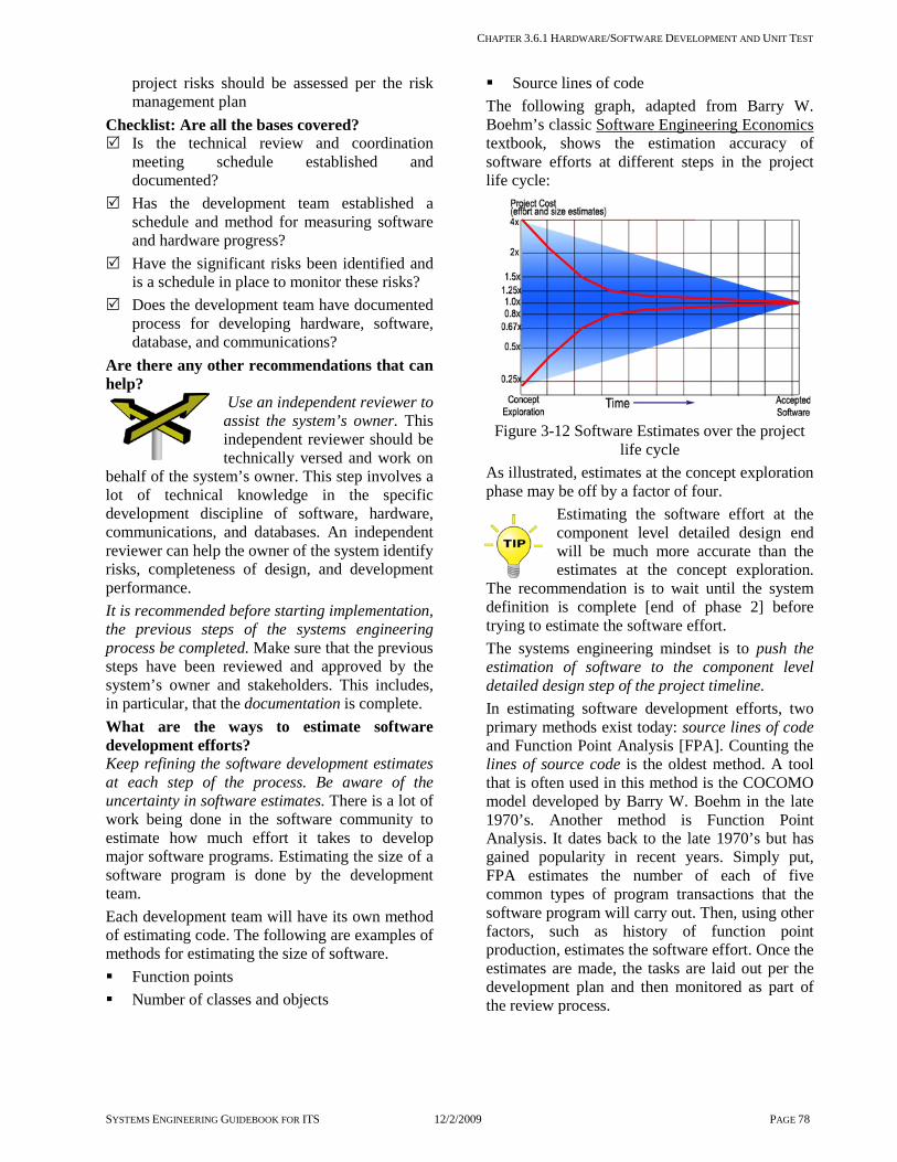
CHAPTER 3.6.1 HARDWARE/SOFTWARE DEVELOPMENT AND UNIT TEST
SYSTEMS ENGINEERING GUIDEBOOK FOR ITS 12/2/2009 PAGE 78
project risks should be assessed per the risk management plan
Checklist: Are all the bases covered? Is the technical review and coordination
meeting schedule established and documented?
Has the development team established a schedule and method for measuring software and hardware progress?
Have the significant risks been identified and is a schedule in place to monitor these risks?
Does the development team have documented process for developing hardware, software, database, and communications?
Are there any other recommendations that can help?
Use an independent reviewer to assist the system’s owner. This independent reviewer should be technically versed and work on
behalf of the system’s owner. This step involves a lot of technical knowledge in the specific development discipline of software, hardware, communications, and databases. An independent reviewer can help the owner of the system identify risks, completeness of design, and development performance. It is recommended before starting implementation, the previous steps of the systems engineering process be completed. Make sure that the previous steps have been reviewed and approved by the system’s owner and stakeholders. This includes, in particular, that the documentation is complete. What are the ways to estimate software development efforts? Keep refining the software development estimates at each step of the process. Be aware of the uncertainty in software estimates. There is a lot of work being done in the software community to estimate how much effort it takes to develop major software programs. Estimating the size of a software program is done by the development team. Each development team will have its own method of estimating code. The following are examples of methods for estimating the size of software. Function points Number of classes and objects
Source lines of code The following graph, adapted from Barry W. Boehm’s classic Software Engineering Economics textbook, shows the estimation accuracy of software efforts at different steps in the project life cycle:
Figure 3-12 Software Estimates over the project
life cycle As illustrated, estimates at the concept exploration phase may be off by a factor of four.
Estimating the software effort at the component level detailed design end will be much more accurate than the estimates at the concept exploration.
The recommendation is to wait until the system definition is complete [end of phase 2] before trying to estimate the software effort. The systems engineering mindset is to push the estimation of software to the component level detailed design step of the project timeline. In estimating software development efforts, two primary methods exist today: source lines of code and Function Point Analysis [FPA]. Counting the lines of source code is the oldest method. A tool that is often used in this method is the COCOMO model developed by Barry W. Boehm in the late 1970’s. Another method is Function Point Analysis. It dates back to the late 1970’s but has gained popularity in recent years. Simply put, FPA estimates the number of each of five common types of program transactions that the software program will carry out. Then, using other factors, such as history of function point production, estimates the software effort. Once the estimates are made, the tasks are laid out per the development plan and then monitored as part of the review process.

CHAPTER 3.6.2 INTEGRATION [SUB-SYSTEM AND SYSTEM LEVEL INTEGRATION]
SYSTEMS ENGINEERING GUIDEBOOK FOR ITS 12/2/2009 PAGE 79
3.6.2 Integration [Sub-system and System Level Integration]
OBJECTIVE: Integration is the process of successfully combining hardware and software components, sub-systems, and systems into a complete and functioning whole.
DESCRIPTION: Integration is an iterative process: taking hardware and software components forming them into complete sub-system elements combining the sub-system elements into larger combined sub-systems combining all sub-systems into the final system Integration planning starts when the project activities are first defined. The next major input occurs when the sub-systems are identified during the high-level design and project architecture step. Finally, integration is performed when the hardware and software components are developed and delivered by the development team. Integration and verification are closely linked processes in which one follows the other until the entire system is ready for operational deployment. A complex project may need a written Integration Plan. Integration activities are driven by: system requirements internal interfaces within the system external interfaces to legacy systems and the deployment strategy Integration activities are performed iteratively along with verification.
CONTEXT OF PROCESS:
INTEGRATION PROCESS
CHAPTER 3.6.2 INTEGRATION [SUB-SYSTEM AND SYSTEM LEVEL INTEGRATION]
SYSTEMS ENGINEERING GUIDEBOOK FOR ITS 12/2/2009 PAGE 80
Inputs: Concept of Operations describes the way the system is to operate and will assist in the verification and integration effort. System and Sub-system Requirements contain the requirements for the sub-systems / systems. High Level Design [project architecture] defines the integration activities to be performed. Component Level Detailed Design contains the design constraints for the sub-systems/systems to be integrated. Deployment Strategy defines when and where the sub-systems are to be grouped and deployed. Developed hardware / software components and sub-systems have completed integration and are ready for the next level of verification.
Control: Project Plan/SEMP establishes a high level description of the systems engineering plan for integration. Configuration Management Plan sets the configuration controls needed during integration.
Enablers: Stakeholder involvement is needed to assist with integration with external systems and devices.
Outputs: Integration Master Plan establishes the goals and high level approach to integration. Integration Plan [optional] documents the high level plan and process for integrating the system. This is part of the Project Plan/System Engineering Management Plan [SEMP]. Integrated sub-systems / system means they are ready for verification.
Process Activities: Plan integration activities: Planning includes the sequence in which the various components of the system should be integrated, the needed resources, schedule, and coordination activities [if multiple development teams are involved], and the documented plan itself. A number of factors influence the integration sequence, including the order in which components and sub-systems are produced by the development team[s]. Each integration step should produce a product that implements a related set of functionality. For example, an operator interface may be integrated with a loop data collection function before the loop data function is integrated with an incident management function. Define integration activities: At the high level design [project level architecture] integration activities are defined. Sub-systems, internal interfaces, and external interfaces are defined. They are the key points for integration. Also, at the high level design, the number of integration/verification cycles are defined. Perform integration activities: The first step is to ensure that the integration team has access to the resources needed to support the planned integration step. Special attention has to be paid to resources that come from outside integration team's organization. These could include: support from the developers or manufacturers, support from other agencies with an external interface, a testing environment [e.g. workstations, communications, and interface simulators.], and, of course, the various sub-systems to be integrated. As integration proceeds, issues are monitored through periodic reviews as follows: is progress being made in accordance with the schedule are the problems are being resolved in a timely manner are verify requirements changes are being addressed in accordance to the Configuration Management Plan are resources being made available when needed is there adequate coordination between development teams As the cycle of integration and verification is repeated, lessons learned during a verification step may have to be fed into the next round of integration. Integration should be complete enough that subsequent verification proceeds with minimum disruption.

CHAPTER 3.6.2 INTEGRATION [SUB-SYSTEM AND SYSTEM LEVEL INTEGRATION]
SYSTEMS ENGINEERING GUIDEBOOK FOR ITS 12/2/2009 PAGE 81
Where does Integration take place in the project timeline?
Is there a policy or standard that talks about integration? FHWA Final Rule does not specifically mention integration as one of the required systems engineering analysis activities. EIA 731 and CMMI have identified best practices for integration. Which activities are cr itical for the system’s owner to do? Determine the need for a written Integration
Plan Review and approve the Integration Plan, if
one is needed Manage the timely acquisition of resources
needed to support integration Track the progress of integration with respect
to the project schedule. Intervene if the progress falls behind the schedule
How do I fit this step to my project? [Tailor ing] There are a number of factors which make a project complex. The same factors that influence other steps in the systems engineering process also influence the integration process. Integration of sub-systems with external interfaces is nearly always required. The major impact on tailoring the integration process is the degree of formality needed to verify compliance with requirements to stakeholders. The simpler the system, the smaller the project team and the fewer the number of external stakeholders [stakeholders with systems that
interface with the target system], the less formal the integration process needs to be. What should I track to reduce project r isk and to get what is expected? [Metr ics] The number of times failures are detected
during integration is a good indicator of the quality of the development effort
The number of times a later stage of integration turns up a problem that should have been detected in an earlier stage of integration is a good indicator of the quality of the integration effort
The number of times problems are not found in integration but are discovered during verification is an even stronger indicator of the quality of the integration effort.
Checklist: Are all the bases covered? Are integration activities included in the
master project schedule? Does the plan for integration and verification
support the strategy for deployment? Based on project complexity, is a written
Integration Plan required? Are the external systems needed to support
integration available, or does the interface need to be simulated?
Have the components to be integrated been placed under configuration control?
Are the development teams available to promptly fix problems uncovered during integration?

CHAPTER 3.6.2 INTEGRATION [SUB-SYSTEM AND SYSTEM LEVEL INTEGRATION]
SYSTEMS ENGINEERING GUIDEBOOK FOR ITS 12/2/2009 PAGE 82
Are there any other recommendations that can help? The importance of a good strategy and verification of design:
Develop a good integration strategy: A successful integration process is based on a sound strategy which will give it direction
and completeness. This same strategy will be needed to guide the verification and initial deployment activities. This strategy is based on a set of goals that were established early in the planning stages of the project. These goals answered the following questions: In what order does one need to deploy these
capabilities in order to provide useful operational capabilities at each step?
How does one want to evolve the operational capabilities at a location in order to provide increasingly useful operational capabilities?
What are the funding limitations? Of course that last goal, spending the available funds in the most effective manner, is usually the hardest to solve. Since these goals are related to deployment, this subject will be revisited in Chapter 3.6.4. Nevertheless, the integration plan, as well as the design, must be fashioned to meet these deployment goals. As has been stated before, "integration is a more informal activity than verification". As such, the preparation of detailed plans and procedures is generally not required. In fact, if such structure is felt to be necessary, the procedures used for subsequent verification can also be used as part of the integration activity. Thus, the verification dry-run [see the verification chapter] could also be seen as part of the integration effort. Verification of design: Integration is more than a verification of requirements; it is also a verification of the design. It explores the details of both the hardware and software. It needs, for instance, to look at hardware and software interfaces at a much lower
level than just exercising the functional requirement. Generally, this informal integration approach is effective since it avoids the costs of more formal documentation. Still, it needs to be carefully monitored. It needs adequate project support. It also needs the right people on the integration team.
A closer look at integration and verification and levels of integration
Integration and verification are iterative processes with each other. Integration puts a sub-system [or system] together from components
[and/or other sub-systems], and informally assures that everything is working as it should in accordance with the requirements. Verification formally tests the assembled system [or sub-systems] to show that all applicable requirements are met. The figure shows this cycle and how it is repeated until the entire system can be accepted.
Levels of integration means that the levels of integration needed for a system will match the number of levels of the system hierarchy. For example, a traffic control system would have the following 3 levels of hierarchy:
the component level [the loops and field controllers] would be the first level of integration
the sub-system level [field controllers with field masters] would be the next level of integration
the system level [host with the field masters and field controllers] would be the final level integration.
More complex systems may have additional levels of hierarchy and integration. For example, in regional ITS, the traffic control system example above may need to integrate with a freeway ramp metering system for coordination. This would represent a fourth level of integration and so on.
Figure 3-13 Integration and Ver ification are Iterative

CHAPTER 3.6.3 VERIFICATION [SUB-SYSTEM AND SYSTEM LEVEL VERIFICATION]
SYSTEMS ENGINEERING GUIDEBOOK FOR ITS 12/2/2009 PAGE 83
3.6.3 Ver ification [Sub-system and system level ver ification]
OBJECTIVE: The verification process is used by the system’s owner and by other stakeholders to show that the as-built system, sub-system, and components meet all of their requirements and design. This process is used by the system’s owner and other stakeholders to accept the system products from the development team.
DESCRIPTION: Verification is the process that proves the system [or sub-system or component] meets its requirements and matches the design. Since verification is based on requirements and design, one of the keys to successful and effective verification is well-written and complete requirements and design documents. These requirements and design elements are developed, reviewed, and approved earlier in the project timeline before the system is developed or procured. Planning for the verification activities starts with the System Engineering Management Plan [or with the Project Plan if a SEMP is not needed]. At this level, the general structure of the verification tasks is identified and shown to be compatible with the desired deployment plan and with the system concept. The Verification Plans are best written at the same time the requirements of the system, sub-system, or component are developed. This is done to show that the requirements, as written, can be verified. At the end of the detailed design effort, verification procedures can be written. These procedures are the detailed steps to be taken to verify each requirement and design element. There must be a clear trace from each requirement, through the Verification Plan, down to a detailed step in the verification procedure. Verification is performed iteratively. It starts with the integration activities at the component level. It progresses through the sub-system development to the verification of the entire system. Final verification for system acceptance is done with the installed system. At this point, system development is complete and the deployed system is ready for operations. The system’s owner and stakeholder involvement is essential for verification.
Verification answers the question “Was the system built ‘right’”
CONTEXT OF PROCESS:
VERIFICATION PROCESS

CHAPTER 3.6.3 VERIFICATION [SUB-SYSTEM AND SYSTEM LEVEL VERIFICATION]
Systems Engineering Guidebook for ITS 12/2/2009 PAGE 84
Inputs: Concept of Operations describes the way the system is to operate and will assist in the verification and integration effort. System and Sub-system Requirements contain the functional and performance requirements to be verified. Design Specifications contain the design elements to be verified. Integration Plan [optional] shows how the integration steps are to be done iteratively with verification. Deployment Strategy [optional] defines when and where verification takes place. Integrated sub-systems/system is ready for verification.
Control: Project Plan/Systems Engineering Management Plan [SEMP] establishes a high level description of the project’s plan for verification. Configuration Management Plan sets the configuration controls needed during verification.
Enablers: Stakeholder involvement is needed for verification conduct and to show critical stakeholders that the system meets its requirements. Technical Reviews include a test readiness review to determine all resources needed for a verification step are available. Traceability to the verification plan & procedures ensures that all requirement are being verified.
Outputs: Verification Master Plan is included in the Project Plan/SEMP to establish general guidelines for this important part of the systems engineering process. Verification Plan documents the plan for verifying system and sub-system requirements. Verification Procedures document the details of each verification step. Verification Reports document results of each verification step. Verified sub-system/system ready for further integration, deployment, or operational use.
Process Activities: Plan verification activities in SEMP / Project Plan During the project planning stage, a strategy for verification is developed which is compatible with the system concept and the deployment objectives. Develop Verification Plan Verification Plan is written for each level [component, sub-system or system]. The plan will develop a verification case and method for each requirement and for each design element contained in the applicable Specification. In addition to the verification cases, the Verification Plan will give general guidance for all of the verification activities. These include: the identification of all verification participants, descriptions of their roles and responsibilities, and a schedule for verification activities. Finally, it includes: the identification of test equipment needed and of software drivers or simulators needed to model the interfaces to the system under test. Trace between specifications and test cases Each test case is traced to a specific requirement to ensure all requirements are verified. Develop Verification Procedures These procedures are the detailed step-by-step actions and the expected outcome for each verification case. Perform verification When all needed resources are ready, verification is performed according to the approved procedures. Document verification results Prepare a Verification Report for each verification step.

CHAPTER 3.6.3 VERIFICATION [SUB-SYSTEM AND SYSTEM LEVEL VERIFICATION]
Systems Engineering Guidebook for ITS 12/2/2009 PAGE 85
Where does Ver ification take place in the project timeline?
Is there a policy or standard that talks about verification? FHWA Final Rule does not specifically mention general verification of requirements. It does require inter-operability tests relating to use of ITS standards. IEEE std. 1012 talks about independent verification and validation. CMMI identifies best practices. Which activities are cr itical for the system’s owner to do? Identify and recruit stakeholders who are
needed to participate in verification Review and approve all documents Witness critical verification steps How do I fit this step to my project? [Tailor ing] Some level of verification is needed to accept the system. The formality with which verification is performed can be tailored to the budget, size, and complexity of the project. For a small simple project with few stakeholders, it only may be necessary to use the requirement document itself as a checklist and extemporize the procedures on the fly. Thus, no verification documents are needed. The system’s owner determines what level for verification formality and documentation is needed to satisfy the complexity of the project. What should I track to reduce project r isk and to get what is expected? [Metr ics] Number of verification failures and their cause [poor requirements, design errors, inadequate integration], is an indication of the quality of products from the development team.
Checklist: Are all the bases covered? [ Was a Verification Plan developed and
approved? Were all requirements traced to a Verification
Plan test case? Were Verification Procedures developed and
approved? Were the key participants identified and
trained? Were all resources needed for testing in-
place? Were all participants notified of the testing
schedule? Was a Verification Report prepared? Are there any other recommendations which can help? A closer look at the stages of verification, verification techniques, and the rules for performing verification Key stages of ver ification A project may require three or more different stages of verification: sub-system, system, and commissioning. The first is iterative with integration. The last is iterative with deployment. System verification and acceptance falls between the two. Of course, special project situations may require some tailoring, and perhaps additional stages, for complete verification. Sub-system Verification – As discussed in
3.4.2, High Level Design, a system is often divided into two or more sub-systems for ease of development. Once the integration process

CHAPTER 3.6.3 VERIFICATION [SUB-SYSTEM AND SYSTEM LEVEL VERIFICATION]
SYSTEMS ENGINEERING GUIDEBOOK FOR ITS 12/2/2009 PAGE 86
has produced one of these sub-systems, it is verified against its requirements. Once verified, the sub-system can be integrated with other sub-systems.
System Verification step covers all integrated sub-systems and is usually used to accept the entire system. For many requirements, this is the last time they are verified. As such, this step is the most formal, reviewed, witnessed, and where there are failures, receives the most attention. It may not be as exhaustive as sub-system verification. Yet, it still must be extensive enough to produce a solid feeling among the stakeholders that the system does what it is supposed to do.
Sub-system and system verification is best done in a highly controlled environment, especially with respect to external inputs to the system under test. This usually requires software to simulate or model the external world. For instance, a traffic signal simulator or roadway sensor simulator may be needed to test a new central control system.
Commissioning is accomplished after the system is deployed to verify that the system works when installed. Commissioning is generally more cursory than system verification. It is just enough to verify that everything is still working. However, in some circumstances, a part of system verification must be deferred to the time of commissioning; again using simulated inputs as needed to complete the needed verification prior to commissioning.
Verification of the system’s ability to work with the complete set of real sensors must wait until after deployment.
It may be necessary to overlap the last two stages of verification. System verification can be started in a development environment
using simulated inputs from sensors and external system then completed after deployment and commissioning using real sensors and real external systems. While verification with simulated inputs may be necessary, final verification with real inputs is almost always mandatory.
Verification techniques Four techniques are used to verify requirements: inspection, analysis, test, and demonstration. Inspection: the visual verification of a
requirement, such as a color, a size, and model number.
Analysis: the mathematical analysis of collected data to verify a requirement
Demonstration: the use of the system itself to verify the expected output, such as a response to an operator input. This is the most commonly used verification technique.
Test: similar to a demonstration except external test equipment is used.
A special type of demonstration is called a burn-in is used to identify and resolve random or latent defects [thermal, memory leaks, and race conditions]. General rules for performing ver ification notify all stakeholders of the schedule for
verification and clarification of their roles and responsibilities
identify and document the configuration of the system under test
define the process for recording all test actions and the system’s response
define the process for dealing with all unexpected responses
define the process to manage anomalies define a plan of action based on this analysis.
[e.g. repeat the test, revise procedure, change the requirement, suspend the test, fix the system and retest]
Be careful of requirements creep. During verification some stakeholders, especially if they
have not been involved in the design activities, will want to rewrite or add to the system requirements. A typical example is a desire to change the
operator interface. There is a cost and schedule risk of doing this and the best way to avoid these occurrences is to ensure that the correct stakeholders are involved in establishing the requirements and designing the system from the start.

CHAPTER 3.6.4 INITIAL SYSTEM DEPLOYMENT
SYSTEMS ENGINEERING GUIDEBOOK FOR ITS 12/2/2009 PAGE 87
3.6.4 Initial System Deployment
OBJECTIVE: The deployment process for tested system/sub-systems installs them in the intended environment for operations.
DESCRIPTION: Deployment is the final design/build step in the development of a system. The deployment strategy must reflect the plan for the project. It must provide an operationally useful component of the system at each step of the process and deployment location. The deployment strategy may involve a single deployment to a single site. Or, may have to deal with multiple, partial deployments to multiple sites over an extended period of time. A complex deployment also may require post acceptance testing at each site. A written Deployment Plan may be necessary to ensure a successful deployment, especially if multiple agencies are involved. A Deployment Plan will define all the work steps for complete deployment, and who does them. At each deployment site the hardware and software is configured, installed, and then tested to show it is ready to support operations.
CONTEXT OF PROCESS:
INITIAL SYSTEM DEPLOYMENT PROCESS
CHAPTER 3.6.4 INITIAL SYSTEM DEPLOYMENT
SYSTEMS ENGINEERING GUIDEBOOK FOR ITS 12/2/2009 PAGE 88
Inputs: Concept of Operations provides general guidance on how the system is to be operated and therefore on how it must be deployed. Accepted and verified sub-systems / systems are ready for deployment. Support Products includes training materials, users, and maintenance manuals.
Control: Project Plan/SEMP establishes a high level description of the project management and system engineering plan for deployment.
Enablers: Stakeholder involvement is needed to support the deployment activities.
Outputs: Deployment Master Plan establishes the goals and a strategy for deployment. This is included in the Project Plan/System Engineering Management Plan [SEMP]. Deployment Plan [optional] documents the high level plan for deploying the system. Deployed system is ready for operational use.
Process Activities: Develop Deployment Strategy The strategy defines what capabilities and parts of the overall system will be deployed, where the part will be deployed, and the timing of the deployment. The Strategy is used to allocate funding for the project over time by identifying what the timeline will be for the projects. Write Deployment Plan [optional] The following are considerations to prepare, review, and the approving of a written Deployment Plan: A complex deployment schedule with multiple deployments of different configurations to multiple sites.
For instance, a deployment of a number of Transportation Management Systems statewide with different configurations at each site
The needed facilities, such as electrical, air conditioning, communications infrastructure, and lighting needed to support the system. In addition, personnel training will be needed for operations & maintenance. This must be planned and performed in time for the delivery of the system
Several stakeholders whose activities must be coordinated for the deployment effort, especially stakeholders from different organizations and agencies. For instance, even a single ITS site may have multiple inter-agency interfaces that, when implemented, will change the operations at these external systems
Stakeholder consensus for the deployment plan by showing the analysis of alternatives that led to the selection approach. This is especially useful for trying to balance operationally viable deployment steps with funding availability
Whether or not a written Deployment Plan is needed, the planning must consider the timing deployment of what parts of the system, and with what capabilities. Perform deployment activities Managing deployment follows the same path that integration and verification have followed. First, all needed resources must be identified, obtained, and trained, including all facilities [electrical, communications, lighting], and personnel training for operations & maintenance. Then, just prior to the start of each deployment step, the readiness of those resources is determined and any work-around plans put into effect. During the performance of a deployment step, progress should be monitored and reviewed with the deployment team on a regular basis. The final step of a deployment is usually an integration and verification of the deployed system prior to operational acceptance.

CHAPTER 3.6.4 INITIAL SYSTEM DEPLOYMENT
SYSTEMS ENGINEERING GUIDEBOOK FOR ITS 12/2/2009 PAGE 89
Where does Initial System Deployment take place in the project timeline?
Is there a policy or standard for deployment? FHWA Final Rule does not specifically mention initial system deployment as one of the required systems engineering analysis activities. Which activities are cr itical for the system’s owner to do? In concert with the operating agencies,
develop, review, and approve the goals and a general strategy for deployment
Identify and recruit agency stakeholders to participate in deployment
Review and approve all deployment plans Monitor deployment activities. Witness
critical post deployment verification How do I fit this step to my project? [Tailor ing] Depending on various factors of the project, deployment can range from very simple to very complex. The number of deployment steps and the number of stakeholders involved in deployment are the best indicators of complexity, although there may be others of equal importance. If either of these factors warrant, then project management may decide that the expense of preparing, reviewing, and approving a Deployment Plan document is justified. If it is not, then the guidance in the Program Plan and in the SEMP, plus a qualified person in charge of deployment, is quite sufficient.
What should I track to reduce project r isk and to get what is expected? [Metr ics] Deployment involves elements of both integration and verification and each of these processes has its own set of useful metrics. Beyond that, tracking progress to the schedule is the most useful thing project management can do to reduce project risk and get what is expected. Checklist: Are all the bases covered? Has a comprehensive set of deployment goals
been developed? Can those deployment goals be traced into the
deployment strategy? Does the deployment strategy consider
available funding? Does each step in the deployment strategy
produce an operationally useful and maintainable deployed system?
Does the deployment strategy minimize the risk of interference to on-going operations?
Does the deployment strategy offer a viable operational fallback at each step of the process?
Are all stakeholders in a deployment step aware of their roles and responsibilities?
Are all resources needed for a deployment step available?
Has a work-around plan been developed in case a needed resource is not available?

CHAPTER 3.6 SYSTEM DEVELOPMENT AND IMPLEMENTATION
SYSTEMS ENGINEERING GUIDEBOOK FOR ITS 12/2/2009 PAGE 90
Are there any other recommendations that can help?
Factors that should be considered when developing a deployment plan:
If multiple locations are involved, the final desired configuration at each site
If multiple sites are involved, the relative sequence in which each site needs to reach its desired final configuration
The dependence on prior deployments to this or any other site. For instance, an operational site only may be viable if a maintenance center needed to support the operational site has been previously upgraded or installed
If a phased deployment is required [say due to a funding profile spread over several fiscal years] then a number of other factors must be considered, including: - Each incremental deployment phase must
result in an operationally useful system - Each incremental deployment phase and
all dependencies must be included or already installed. [ It does little good to install capability B, if capability A is needed to use B, but A is not installed until later
- The cost of each incremental deployment phase cannot exceed the incrementally available funds
Using the Deployment Plan for selling the strategy and to provide planning and advice for a “r ibbon cutting” ceremony Use the Deployment Plan document to “sell” the selected deployment strategy. This is much more likely when a relatively complex set of deployment goals have to be met, such as when the conflicting goals of operationally useful but funding-constrained deployment phases are required. It then becomes necessary to show that not only the selected strategy meets those goals;
but meets them better than any alternative strategy. The Deployment Plan is then an excellent place to document this strategy selection since much of the information is eventually needed for implementing the deployment plan. Plan for the “ribbon cutting” ceremony- Since the deployment activity is the last step in the development process and the point where the system is turned over to the system’s owner, there is sometimes a desire to turn that hand-over into a “ribbon cutting” ceremony. If this, or any other public relations type of activities, is required of the project office [as opposed to being the responsibility of the operating organization], then planning for this activity should be included as part of the deployment effort, and, if one is written, documented in the Deployment Plan.
Make sure that the operational and support team is in place when the system is commissioned into operations. In addition to the
challenge of deploying an operationally viable system that meets all of its requirements, very often two other conditions have to be met. The first is that the operations people have to be available and trained in the new system’s features. This may involve the recruitment of additional staff and certainly includes operational training for both new and existing staff. The second condition is to ensure that adequate maintenance support will be available. Not only does this require trained staff, but also sometimes additional facilities are required. Sometimes an existing maintenance facility has to be upgraded with additional test equipment and additional spare parts to support the system’s new hardware. Sometimes a software test bed has to be created to give support staff a place to fix and test the existing software products and to develop upgrades to those same products, without interfering with normal use of the operational system.

CHAPTER 3.6.4 INITIAL SYSTEM DEPLOYMENT
SYSTEMS ENGINEERING GUIDEBOOK FOR ITS 12/2/2009 PAGE 91
3.7 Validation, Operations & Maintenance, Changes & Upgrades
Figure 3-14 Phase 4 - Validation, O&M, Changes & Upgrades Roadmap

CHAPTER 3.7.1 SYSTEM VALIDATION
SYSTEMS ENGINEERING GUIDEBOOK FOR ITS 12/2/2009 PAGE 92
3.7.1 System Validation OBJECTIVE Validation is an assessment of the operational system. Validation ensures the system meets the intended purpose and needs of system’s owner and stakeholders. DESCRIPTION: Validation starts with a clearly stated set of needs. These needs are the basis for the system requirements. When the system is developed, the system is assessed against these needs. The validation process has three primary activities: Planning: With stakeholder involvement planning starts at the beginning of the project timeline. The plan includes who will be involved, what will be validated, what is the schedule for validation, and where the validation will take place. Validation strategy: This defines how the validation will take place and what resources will be needed. For example, whether a before and/or an after study will be needed. If so, the before study will need to be done prior to deployment of the system. Perform validation: After the system has been accepted, the system should be assessed based on planning & strategy and the results documented. The system’s owner and stakeholders are responsible for the validation of the system. The primary systems engineering activity is to assist in development and execution of all three activities.
Validation answers the question “Was the ‘right’ system built?” CONTEXT OF PROCESS:
SYSTEM VALIDATION PROCESS

CHAPTER 3.7.1 SYSTEM VALIDATION
SYSTEMS ENGINEERING GUIDEBOOK FOR ITS 12/2/2009 PAGE 93
Inputs Verified system after the system has been verified [accepted by the system’s owner]; it is ready for validation testing. Concept of Operations provides the goals, objectives, and needs to be assessed. Control Project Plan/Systems Engineering Management Plan [SEMP] includes the validation plan used to identify the strategy, schedule, and resources for validation. Enablers Stakeholder involvement includes the system’s owner and its stakeholders. Each will have needs that the system is intended to address. When the assessment is performed, the stakeholders must be in agreement on the plan, strategy, and outcome of the assessment. Traceability from the concept of operations to the validation plan & procedures ensures that the user needs are validated when the system is deployed. Outputs Validation Master Plan specifies what needs to be validated, where, and when. This becomes part of the Systems Engineering Management Plan [SEMP]. Validation Plan defines how the validation will be performed. In particular, it specifies whether a before and after study is needed. If special environmental conditions or resources are needed to conduct the assessment. Validated system [Assessment of the system] is one that has been assessed against the initially stated needs. It may have fallen short in some areas and exceeded in others. The short falls are used to identify new requirements for the evolution of the system. Validation report documents the results of the validation process: the strengths and weaknesses of the system. It shows where improvement can be made. Process Activities: Develop validation strategy Validation planning occurs at the beginning of the project and is part of the Systems Engineering Management Plan. The plan includes the environment for validation resources. A validation plan is developed as part of the systems planning and concept of operations. Plan validation Strategies include alpha testing, beta testing, and an evaluation period for validation. If before and after studies are needed, it will be identified in the strategy. Validate system [Assessment of the system capabilities in operations] Once the system has been accepted and deployed, the functionality and performance of the system are validated [assessed] against the needs, goals, and objectives as stated in the concept of operations. Also, the system is assessed in the “real-world” operations to evaluate the system against expectations of the system’s owner and stakeholders. This evaluation can result in one of the following:
Case 1] System performs as expected. Action: Expand the system to address additional needs and document the emergent qualities of the system as it is in operations. New requirements will be developed for the next evolution of the system.
Case 2] Needs were not clearly articulated and the system falls short of expectations. Action: Improve the process used for the elicitation of needs and involvement of stakeholders and then correct the definition of needs. Develop the correct set of requirements for the next evolution of the system. Case 3] The problem space was not understood and the needs were based on the ill-defined problem. Actions: Improve the problem definition process and the elicitation processes. Re-evaluate the problem space and needs to ensure it is understood for the next evolution.

CHAPTER 3.7.1 SYSTEM VALIDATION
SYSTEMS ENGINEERING GUIDEBOOK FOR ITS 12/2/2009 PAGE 94
Where does the Validation take place in the project timeline?
Is there a policy or standard that talks about Validation? FHWA Final Rule does not specifically mention general validation practices to be followed. IEEE-1012 Independent verification and validation and CMMI identify best practices. Which activities are critical for the system’s owner to do? Lead in developing the plan, strategy, and
performing the validation of the system Gain stakeholder involvement in the
validation process and gather their expectations for the system and performance outcomes
Participate in requirements walkthrough and ensure the correct requirements are being developed [Validating the requirements]
How do I fit these activities to my project? [Tailoring] There is great latitude in system validation. It is dependent on institutional agreements (State and FHWA requirements) on a per project basis. In signal upgrade systems a simple before and after study on selected intersections may be sufficient to validate. In a more complex system a number of evaluations may be needed. This validation may be needed for each stakeholder element, each sub-system [e.g., camera, CMS, and detection system]. It may be done on a sample area of the system or comprehensively. Getting this addressed with the stakeholders in the planning stage is very important.
What should I track in this process step to reduce project risks and get what is expected? [Metrics] On the technical side: Each need, goal, and objective should have an element that can be measured and tracked throughout the development. For example, for an incident management system the goal of the planned system may be to reduce incident management time by 30%. The technical metric is “time”. This includes, for example, detect time, time to verify, response time, and time to clear. The time would be the metric to monitor throughout the development. On the project management side: At this point the development is complete. As the project manager, it will be important to validate the systems as soon as possible and IAW the plan. If validation is delayed too long, the assessment may become more difficult to accomplish [lack of resources and interest] and [with the changing environment] the results of the assessment may become diluted. [E.g. change in traffic patterns, increase in congestion over time]. Checklist: Are all the bases covered? Were all the needs clearly documented? With each need, goal, and objective is there
an outcome that can be measured? Are all the stakeholders involved in the
validation planning and the definition of the validation strategy?

CHAPTER 3.7.1 SYSTEM VALIDATION
SYSTEMS ENGINEERING GUIDEBOOK FOR ITS 12/2/2009 PAGE 95
Are all the stakeholders involved in the performance of the validation and is there an agreement on the planned outcomes?
Are there adequate resources to complete the validation?
Are the system’s owner and stakeholders participating in the requirements walkthrough and approval process?
Is there adequate systems engineering support for the validation planning, strategy, and performing validation?
Are there any other recommendations that can help?
This is an area of high stakeholder involvement. Ample time should be given to this activity. Clearly identifying measurable needs,
goals, and objectives is critical for assessing the system as well as the development of a good set of requirements for the system. The systems engineering mindset is to “start at the finish line” [what the system is to do and how well it is to do it]. This clear end point is essential for the successful completion of the system. The journey may encounter detours, road blocks, and it may be longer than expected. The validation process helps the system’s owner in making this “finish line” clear to the stakeholders and to the development team.
Validate the system as quickly as possible. There may be a tendency to lose interest once the system has been developed, accepted by the system’s
owner, deployed, and commissioned into service, assuming that the system is doing the job it was intended to do. With Intelligent Transportation Systems [ITS], it is not only the delivery of the project [system] that is important, but that the project [system] delivered meets the users needs.[Was the right system delivered?] This can only be done through the validation process. The system’s owner and stakeholders should follow through as soon as possible with the assessment of the system. What is the difference between Validation and Verification? First let us look at validation, then verification.
Validation determines if the system is being developed will meet the intended needs of the system’s owner and stakeholders when completed. Does the system solve the problem or issue that it was intended to solve? Does it solve it to the expected extent? The needs, vision, goals, and objectives are the starting points for validating the system. It sets the “stake” in the ground and says this is what we want, what problem we intend to solve, and to what extent we want to address the issues. [Performance metrics] The first part of validation is to make sure that the system development starts out on the right track. This is done by validating the requirements of the system this is done on the left side of the Vee during the requirements development phase. Are these the “right” requirements being implemented? This question needs to be addressed early in the project timeline. It requires high stakeholder involvement and an accurate translation of the needs, goals, and objectives into a set of system requirements that can be built. The system’s owner should take ample time to clarify the vision, goals, objectives, and needs. They need to be made measurable. The translation of the needs into system requirements is done using the elicitation process and other techniques. For example, similar systems, technology review, prototyping, and/or modeling. The second part of validation is at the end of development where the system has been accepted and is now put into operations. Does the system do what it was intended to do, and to what extent? Was the “right” system built? Verification is the process which makes sure that what was built matches the requirements. Was the system built the way the requirements and design specified? Was the system built “right”? Both the verification and validation processes are important and necessary. However, it is the validation which views the system from the system’s owner and stakeholder perspective. The verification of the system is viewed from the development team’s perspective. Systems engineering’s goal is to unify these views.

CHAPTER 3.7.2 OPERATIONS & MAINTENANCE
SYSTEMS ENGINEERING GUIDEBOOK FOR ITS 12/2/2009 PAGE 96
3.7.2 Operations & Maintenance
OBJECTIVE: This chapter describes the activities needed to effectively operate and maintain the system in a day-to-day operational environment.
DESCRIPTION: Operations & maintenance involves planning for, and executing, activities, such as operating the system, monitoring system performance, making repairs, hiring and training operators, testing the system after any changes are made, and tuning the system. All systems require regular maintenance. Preventive maintenance involves inspection and proactive actions, such as cleaning, replacement of components prior to the end of their rated life, backing up software, storing data, and replacing components that have become obsolete and unsupported. Reactive maintenance involves correcting faults when they occur. Software maintenance involves correcting malfunctions [bugs] when they are discovered, upgrading components that become obsolete and unsupported, and making minor modifications as needed to improve functionality.
CONTEXT OF PROCESS:
OPERATIONS & MAINTENANCE PROCESS

CHAPTER 3.7.2 OPERATIONS & MAINTENANCE
SYSTEMS ENGINEERING GUIDEBOOK FOR ITS 12/2/2009 PAGE 97
Inputs: Project goals and objectives were identified in project planning. Support products such as users’ manuals and maintenance guides were obtained during system development. Concept of Operations describes the operational scenarios for which procedures are needed. Changes & upgrades provide opportunities to enhance system operation and maintenance.
Control: Project Plan/Systems Engineering Management Plan [SEMP] defines the overall operations & maintenance plan for the project, including the goals and objectives. Configuration management will be used to manage the synchronization of any changes that might occur during the maintenance of the system. This would include replacement elements [spare parts, units, and sub-systems] that would need to be documented as part of the physical audit of the system.
Enablers: Stakeholder involvement is needed to ensure all parties have input and are aware of ongoing activities.
Outputs: Operations & Maintenance Plan documents the procedures, resources, training, and support needed for operating and maintaining the system. Improved operation and maintenance will result for the life of the system. Updated Operation and Maintenance Procedures will be developed as the system changes over time. Requirements for next evolution are captured when identified by operations & maintenance personnel.
Process Activities: Plan Operations & Maintenance During the Concept of Operations phase of the project, two important views of the system are defined, the operations & maintenance views. These views, which envision how the system will operate and be maintained, become the initial planning for the system when it is commissioned into service. Once the system is commissioned into service, these plans are updated to reflect the as-is operational and maintenance environment. The complete Operations & Maintenance Plan should: Identify funding and policies supporting on-going operation & maintenance Identify the aspects of the system needing operation or maintenance Identify the manuals [users, administrators, and maintenance], configuration records, and procedures that
are to be used in operation & maintenance Identify the personnel who will be responsible for operations & maintenance Identify initial and on-going personnel training procedures, special skills, tools, and other resources Identify operations & maintenance related data to be collected and how it is to be processed and reported Identify methods to be used to monitor the effectiveness of operations & maintenance Collect Operations & Maintenance information Operations & maintenance information should be collected throughout the operational life of the system including: disruption in service of the system, restoration measures undertaken, and system performance. Down time and the mean time to repair should be documented and used to assess the average availability of the system. Repair logs should include vendor notice of obsolescence and notice of design changes that will affect the maintainability of the system elements. Perform operations & maintenance Operations & maintenance procedures need to proceed as defined in the Operations & Maintenance Plan. Over time the procedures will need to be refined and updated because the system changes or improved procedures are developed. The Operations & Maintenance Plan needs to be updated as well as the documented procedures, users’ manuals, and maintenance manuals.

CHAPTER 3.7.2 OPERATIONS & MAINTENANCE
SYSTEMS ENGINEERING GUIDEBOOK FOR ITS 12/2/2009 PAGE 98
Where does Operations & Maintenance take place in the project timeline?
Is there a policy or standard that talks about operations & maintenance? FHWA Final Rule requires that the identification of procedures and resources necessary for operations & maintenance of the system be determined in the systems engineering analysis for ITS projects funded with Federal money from the Highway Trust Fund, including the Mass Transit Account.
Which activities are critical for the system’s owner to do? Secure adequate funding and management
support for on-going operations & maintenance
Identify and recruit appropriate agency stakeholders to participate in operations & maintenance
Review and approve the Operations & Maintenance Plan, including any updates
Arrange for on-going monitoring of system performance to ensure it is being operated and maintained adequately
How do I fit this step to my project? [Tailoring] Operations & maintenance are necessary for all systems of any size or complexity. After the ITS system is built, it is made operational and maintained in operational condition for as long as is needed. However, some systems, such as traffic signals, operate autonomously with little routine human input. They need only initial configuration
and periodic review and fine-tuning of the settings. Others, such as a closed circuit television system, require hands-on involvement by a human operator as part of normal operation. But a traffic signal system may involve more intensive maintenance than a CCTV system.
The Operations & Maintenance Plan and associated documents, such as manuals, operating procedures, and system configuration records, should record all the information needed for employees to keep the system operating effectively and for managers to plan for future resource needs. Information provided should include what is needed for day-to-day activities, and also what is needed to plan for occasional activities, such as periodic preventive maintenance and system upgrades. The Concept of Operations, System Requirements, and design documents should be consulted as a checklist of all the system elements and operational aspects that may need coverage in operations & maintenance documentation.
What should I track to reduce project risk and to get what is expected? [Metrics] During system development and implementation, there is no direct measure of the effectiveness of operations & maintenance planning. Once the system is operational, there are ways to monitor its on-going performance.
Although it is often difficult, attempt to measure the on-going operational effectiveness of the system because this is a measure of the success of

CHAPTER 3.7.2 OPERATIONS & MAINTENANCE
SYSTEMS ENGINEERING GUIDEBOOK FOR ITS 12/2/2009 PAGE 99
both operations & maintenance. If feasible, directly measure traveler experiences, such as travel time and safety rates, either continuously or annually.
Otherwise, track indirect performance measures. Have operators record and periodically summarize notable operational successes and failures. Record maintenance actions in a way which enables calculation of descriptive statistics such as, average number of failures per year and mean-time-between failures. Track the number of traveler complaints related to the system. Look for trends that suggest operation or failure rates are deteriorating. Look for ways to make the trend move in the desired direction.
Checklist: Are all the bases covered? Is management support in place for on-going
operations & maintenance (O&M)? Has funding for O&M been identified? Has an O&M Plan been developed and
approved? Were all key stakeholders involved in
development of the O&M Plan? Are resources and training in place for system
start-up? Are established procedures for continually
monitoring the effectiveness of operations & maintenance developed and approved?
Is there a plan for long term upgrades? Are there any other recommendations that can help?
Stakeholders often underestimate or neglect the cost of operations & maintenance. Consider the cost of configuration management, as well as
hands-on operation & maintenance activities.
Remember that most software requires maintenance. This is especially true of software operating on a general-purpose computer. It may be true of embedded software in a specialty device. Even if no defects surface, most software will need to be updated over time to
adjust to changes in external interfaces,
upgrade and/or replace obsolete versions of third party components
be moved to a new computing platform when the original one becomes unserviceable or inadequate
make minor modifications to the functionality to address new requirements, or needs, that were overlooked during initial system development
Configuration management [chapter 3.9.6] keeps the documentation synchronized with the functional and physical characteristics of the system.
Any information that may be needed in the future for any aspect of operation, maintenance, retirement, or replacement should be recorded and kept up-to-date. It is not sufficient to rely on the memory of involved personnel for such information.
Beyond documentation, configuration management involves establishing and following rigorous procedures for controlling changes to the system. Change control ensures operations & maintenance personnel do not make inappropriate or undocumented changes to the system. A Control Change Board reviews and approves or rejects all proposed changes. A change can be as simple as changing a configuration setting, to replacing a major system component. The Change Control Board includes representatives of all parties with an interest or involvement in the system to ensure that all potential options and ramifications [including risk] are considered before proceeding. Development and implementation of any significant changes to the system should follow the same systems engineering process used for the original system development.
Use blanket approvals to cover routine maintenance. Routine maintenance procedures can be handled by blanket approvals of routine activities, including, regular review and a requirement to document all changes. Change control procedures should include periodic audits to confirm that procedures are being followed also, that the functionality and physical characteristics of the system match those required by the approved configuration documentation.

CHAPTER 3.7.3 Changes & Upgrades
SYSTEMS ENGINEERING GUIDEBOOK FOR ITS 12/2/2009 PAGE 100
3.7.3 Changes & Upgrades OBJECTIVE: This step allows the system’s owner to evolve the system to keep pace with changing needs, advancing and changing technology, and/or add system capabilities over time. These changes & upgrades will be performed in a systematic way to maintain or establish system integrity. Integrity in context of systems engineering means that the system’s functional, performance, physical, and enabling products are accurately documented by its requirements, design, and support specifications. The system documentation is accurate and sufficient to the point where changes & upgrades can be performed by any competent development team. This gives the system’s owner the freedom to have the widest possible selection of development teams for evolving the system. DESCRIPTION: The guidance in this step will address upgrades that are planned and ones that are based on new stakeholder needs. This step will also give guidance on implementing upgrades on a system that has not been well documented [see integrity as defined in the objective above]. This step will also give guidance on handling COTS products and applications which may have: become obsolete changed in design aged beyond its contracted support life CONTEXT OF PROCESS:
CHANGES & UPGRADES PROCESS

CHAPTER 3.7.3 Changes & Upgrades
SYSTEMS ENGINEERING GUIDEBOOK FOR ITS 12/2/2009 PAGE 101
Inputs: Legacy System is the existing system to which the upgrade or change will be applied. Legacy System documentation includes the requirements, design, and support documentation. Change Request identifies the new change, upgrade needs, or requirements for the system. Control: Systems Engineering Management Plan [SEMP] is used if the upgrade is a planned upgrade and part of the development strategy. Configuration Management Plan describes how planned and unplanned upgrades & changes would be evaluated, coordinated, and inserted into the legacy system. Enablers: Stakeholder involvement is important when the system is being changed/upgraded, and is essential if the changes & upgrades will impact the stakeholders in some way. Traceability ensures that the integrity is maintained through changes & upgrades as well as supports cost estimation for making changes & upgrades to system. Outputs: Documented legacy system products in the areas of change & upgrade. If the legacy system has not been well documented before the change & upgrade, documented legacy system products are employed. Updated system products and documentation for the new capabilities, as well as the impacted areas of the legacy system. Process Activities: Analyze needed changes & upgrades Planned upgrades are executed IAW the systems engineering management plan [SEMP]. The SEMP may have a development strategy that lays out a plan for the evolution of the system over time. The plan may have several phases to the system evolution. For example, phase 1 may deploy the communications network. Phase 2 may deploy the CCTV [camera system]. Phase 3 may deploy the detection system and so on; until the system has been fully implemented. Each of these phases should be implemented using the forward engineering process. Unplanned changes may be the result of a change in needs, technology obsolescence, requirements, or new stakeholder participation. If the system was well documented, the changes should be implemented using the forward engineering process. The system’s owner’s configuration management process will lay out how the changes will be evaluated, coordinated, and inserted into the system. If the system was not well documented, the reverse engineering process should be performed as described below. An analysis of the legacy system and its documentation is needed to assess to what extent, if any, a reverse engineering process is needed. Reverse engineering Reverse engineering is documenting the legacy system [the system being upgraded/changed]. This includes the interfaces [both internal and external to the system], hardware, software, and support products [original development tools, test plans, and traceability matrix]. This process requires one to analyze the system’s functionality, examine the software [source code] inspect the hardware create or recreate a set of requirements and design documentation that matches the system as it
currently exists Forward engineering Forward engineering is the process of following the Vee Development Model as defined in chapters 3.3-3.7 of this guidebook. All changes & upgrades to the system start with the update of the systems engineering management plan, concept of operations. They are followed by the requirements, sub-systems, high-level design, and detailed design. When evolving, upgrading, or implementing changes to a legacy system, it should be in a forward engineering approach as suggested in this guidebook.
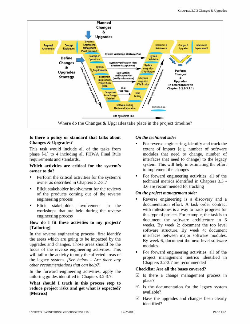
CHAPTER 3.7.3 Changes & Upgrades
SYSTEMS ENGINEERING GUIDEBOOK FOR ITS 12/2/2009 PAGE 102
Where do the Changes & Upgrades take place in the project timeline?
Is there a policy or standard that talks about Changes & Upgrades? This task would include all of the tasks from phase [-1] to 4 including all FHWA Final Rule requirements and standards. Which activities are critical for the system’s owner to do? Perform the critical activities for the system’s
owner as described in Chapters 3.2-3.7 Elicit stakeholder involvement for the reviews
of the products coming out of the reverse engineering process
Elicit stakeholder involvement in the workshops that are held during the reverse engineering process
How do I fit these activities to my project? [Tailoring] In the reverse engineering process, first identify the areas which are going to be impacted by the upgrades and changes. Those areas should be the focus of the reverse engineering activities. This will tailor the activity to only the affected areas of the legacy system. [See below - Are there any other recommendations that can help?] In the forward engineering activities, apply the tailoring guides identified in Chapters 3.2-3.7. What should I track in this process step to reduce project risks and get what is expected? [Metrics]
On the technical side: For reverse engineering, identify and track the
extent of impact [e.g. number of software modules that need to change, number of interfaces that need to change] to the legacy system. This will help in estimating the effort to implement the changes
For forward engineering activities, all of the technical metrics identified in Chapters 3.3 -3.6 are recommended for tracking
On the project management side: Reverse engineering is a discovery and a
documentation effort. A task order contract with milestones is a way to track progress for this type of project. For example, the task is to document the software architecture in 6 weeks. By week 2: document the top level software structure. By week 4: document interfaces between major software modules. By week 6, document the next level software modules.
For forward engineering activities, all of the project management metrics identified in Chapters 3.2-3.7 are recommended
Checklist: Are all the bases covered? Is there a change management process in
place? Is the documentation for the legacy system
available? Have the upgrades and changes been clearly
identified?

CHAPTER 3.7 VALIDATION, OPERATIONS & MAINTENANCE, CHANGES & UPGRADES
SYSTEMS ENGINEERING GUIDEBOOK FOR ITS 12/2/2009 PAGE 103
If this has been a planned upgrade have the systems engineering management plan, concept of operations, requirements, and test plans been reviewed and updated?
If this is a new capability that is added to the system, have the systems engineering plan, concept of operations, requirements, and test plans been developed for this new capability?
Does the upgrade/change impact the project architecture? If so, is the updated project architecture consistent with the regional architecture?
Prior to applying changes/upgrades, have the impacted areas of the legacy system been documented to a level that the changes/ upgrades can be applied using the forward engineering process? [as described in Chapters 3.2-3.7
Are there any other recommendations that can help?
If reverse engineering on a legacy system is needed, it should be done only to the areas that will be affected by the changes/upgrades.
On major systems it may be too costly to document the entire legacy system for minor upgrades and changes. The cost effective approach is to document as needed. Over time, as changes are made, more of the system will be documented. Those areas that never get changed will not be documented.
Continue the reverse engineering process through the implementation of the changes. The reverse engineering process will document the obvious
impacted areas of the legacy system that changes/upgrades will be applied to. As the changes are applied to the affected areas, the implementer must check and continue the documentation effort. Changes to a system may impact areas not intended for change or affect these areas in a subtle, unanticipated way. It will be the implementer and test support that will most likely uncover these types of issues. They must be ready to identify and document these areas.
A closer look at reverse engineering and COTS products and applications Reverse Engineering is documenting an existing Intelligent Transportation Systems functional requirements [what it does], physical characteristics or design [how it does it], and the way it was built and maintained [enabling products]. Legacy system documentation may not have been complete, lost or over time, or was not kept up to date. Traditionally, system’s owners would use the system to the end of its life and start over. Today there is a regional focus on multiple agency involvement, fast-paced changes in technology, and constrained budgets. Systems owners are being driven to evolve their systems and to have greater latitude in development team choices [whether this is done in-house and/or contracted]. In such situations, reverse engineering may be a good alternative to starting over. Reverse engineering for COTS products and applications focuses on interfaces and modularity. Examples of some common elements: workstations and operating systems, databases, changeable message signs, cameras, communications, and detection & traffic control systems. Custom developments focus on user interfaces, data structures, distribution, and applications that analyze, exchange, and translate information. Both the forward and reverse engineering activities should focus on allowing these COTS products to be updated/changed as they become obsolete, have changes to design, or reach the end of their service life. Database management system [DBMS] is a good example of this. When the DBMS reaches the end of life, the system’s owner can choose to stay with the existing DBMS now unsupported, or move to the latest version of the DBMS. If the system’s owner chooses to upgrade, the impact may affect the current operating system and computer hardware. This, then, would impact other applications like the user interface, drivers for the camera system, changeable message signs, and communications. By keeping the applications modular, and interfaces [both internal and external] well defined, the impacts of obsolescence can be minimized.
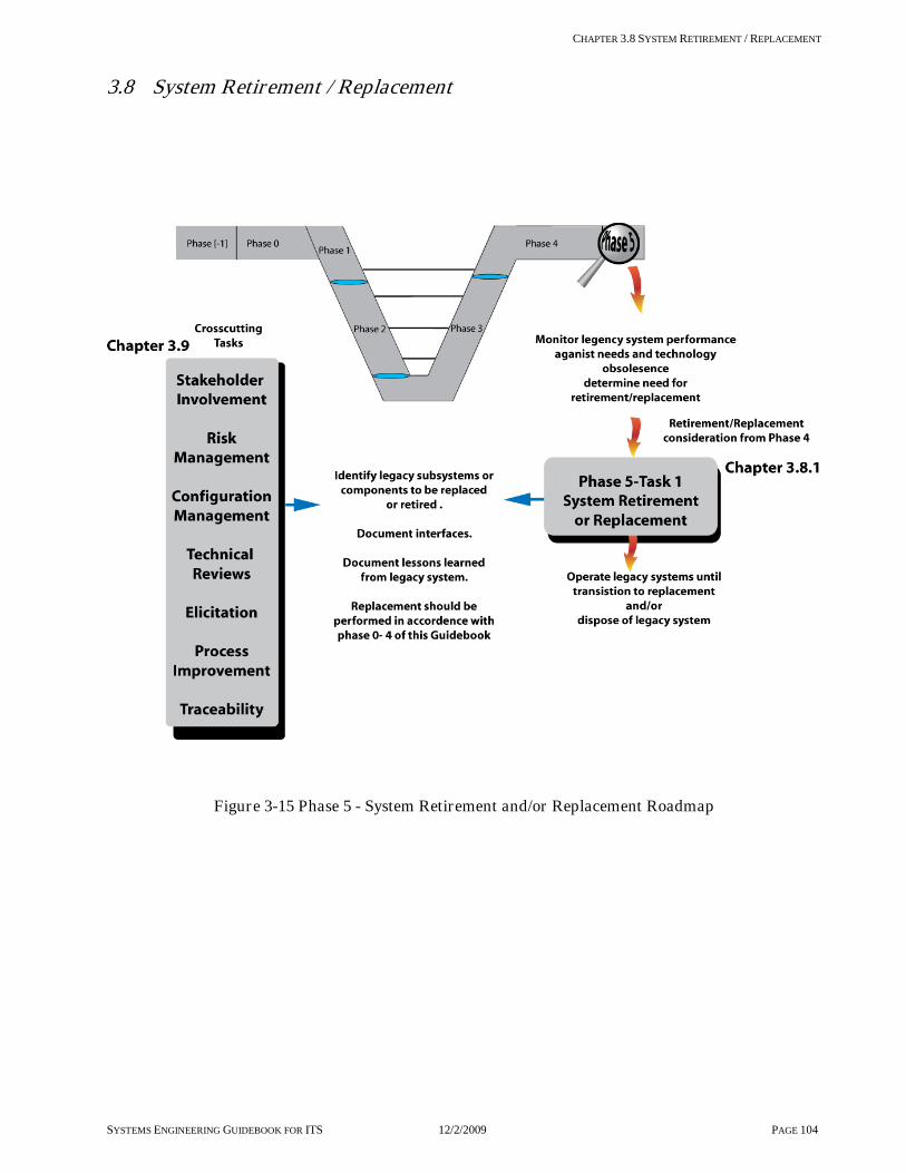
CHAPTER 3.8 SYSTEM RETIREMENT / REPLACEMENT
SYSTEMS ENGINEERING GUIDEBOOK FOR ITS 12/2/2009 PAGE 104
3.8 System Retirement / Replacement
Figure 3-15 Phase 5 - System Retirement and/or Replacement Roadmap

CHAPTER 3.8 SYSTEM RETIREMENT / REPLACEMENT
SYSTEMS ENGINEERING GUIDEBOOK FOR ITS 12/2/2009 PAGE 105
3.8.1 System Retirement / Replacement OBJECTIVE: This step describes what activities are needed to determine when an Intelligent Transportation System or major sub-system needs to be retired or replaced. It also provides guidance on a replacement strategy. DESCRIPTION: This step in the process provides guidance on determining the end of life for a system or sub-system. The end of life for a system or major sub-system can be a planned event or it can occur as a result of the following factors: high cost of operations & maintenance capabilities of the system are no longer needed or cost effective high cost of upgrades and changes Technology obsolescence making the system/sub-system unsupportable. Eventually most system/sub-systems will face some major replacement no matter how well it was developed or maintained. To get the maximum useful life out of a system/sub-system, it must be well designed, documented, and maintained. The following are factors that will certainly shorten the useful life of a system or sub-system: lack of documentation no agreement on a concept of operations inadequate operations & maintenance budget no configuration management process that synchronizes changes with system documentation When a system or sub-system needs to be replaced, a strategy must be developed to migrate to the new system or sub-system. This strategy will become part of the systems engineering management plan. CONTEXT OF PROCESS
SYSTEM RETIREMENT/REPLACEMENT PROCESS

CHAPTER 3.8 SYSTEM RETIREMENT / REPLACEMENT
SYSTEMS ENGINEERING GUIDEBOOK FOR ITS 12/2/2009 PAGE 106
Inputs: Legacy system is the system or major sub-system that is subject to retirement and or replacement. Identified needs are the new user requirements that the legacy system is to address. Change request is the documentation that defines and describes the changes needed to the legacy system or sub-system to meet the new needs. This comes from the configuration management process. Controls: Project Plan/Systems engineering management plan [SEMP] contains the development strategy for the replacement system or sub-system. Configuration Management Plan would have the processes documented which would evaluate the change history, costs, and impacts of changes. Enablers: Stakeholder involvement is essential. Stakeholders who will be affected by the change must be involved in the process of replacement or retirement of the system. Trade Studies is the process tool which can be used to evaluate whether to replace or upgrade the legacy system. This enables the stakeholders to decide what the most cost effective approach is. Traceability ensures that the integrity is maintained through replacement, it also supports cost estimation for making decisions to replace or retire. Outputs: Retirement/Replacement Plan is part of the Project Plan/SEMP that provides the overall strategy for retirement and replacement of the system. Retirement/replacement decision versus upgrading and changing the legacy system. Replacement strategy documents the way the system or sub-system will be replaced. This will become part of the systems engineering management plan for the next evolution of development. Process Activities: Plan retirement and replacement The initial planning of the project may include a replacement plan for the system or sub-system. This may include the deployment of an interim system to address an immediate need. At the time of replacement the system’s owner and affected stakeholders should assess and review the plan, to see that it is still viable. It is important to reassess the plan, especially if the needs have changed or there are new stakeholders involved. Perform Gap Analysis: legacy system capabilities versus capabilities needed The trade studies process can evaluate the cost/benefit of upgrading the current system or replacement of the entire system or some major sub-system[s]. Can the current system evolve to meet the new needs? Was the technology that was used in the current system obsolete and no longer supportable? Are the operations & maintenance costs to the point where a replacement system is more cost effective? Evaluate the cost of upgrade versus replacement The trade study should include life cycle cost analysis, including the operations & maintenance costs, and replacement costs. Issues to address in the evaluation are the vendor support of COTS products and license costs. Is the cost of documenting the existing system prohibitively expensive? Develop the replacement/retirement strategy A strategy for system or sub-system replacement needs to be planned for the replacement of an ITS. This planning may require the upgrade of facilities, floor space, air conditioning, communications, furniture, and other such facilities. Because some systems are safety critical, they have to be operational full-time. In this case, the new system would need to be deployed in parallel with the legacy system. A switch-over plan needs to be created to allow the legacy system to act as a back-up while the new system is being verified and validated. There is a cost and deployment impact of having both systems fielded for that period of time. In other cases, functionality may not be safety critical. In these cases, removing the legacy system prior to the deployment of the new system or sub-system may be more cost effective.

CHAPTER 3.8 SYSTEM RETIREMENT / REPLACEMENT
SYSTEMS ENGINEERING GUIDEBOOK FOR ITS 12/2/2009 PAGE 107
Where does the Retirement/Replacement activity take place in the project timeline?
Is there a policy or standard that talks about Retirement/Replacement? This task would include all the tasks from phase [-1] to 4 including all FHWA Final Rule requirements and standards. Which activities are critical for the system’s owner to do? Participate in the reassessment of the
replacement/retirement plan. If in the original development, this was a planned replacement or retirement, reevaluate the plan to see if the planned replacement is still needed
Be involved in the assessment of alternative replacement systems or sub-systems
Participate in the Configuration Management process to assess the cost of upgrade to the legacy system versus its replacement
Elicit stakeholder involvement and support for the upgrade or replacement decision
Participate in developing the replacement strategy for the system/sub-system
How do I fit these activities to my project? [Tailoring] The replacement strategy can be tailored for the project but factors that constrain this will be if the legacy system or sub-system is critical to public safety and needs to be operational nearly full time. Are there alternates to the legacy system or sub-system operations that can allow it to be inoperable until the new system is in place, verified, validated, and operational?
What should I track in this process step to reduce project risks and get what is expected? [Metrics] On the technical side: In replacing a system or sub-system, identify
the new capabilities [functions] that will be added to the legacy system/sub-system capabilities.
Track and manage the technical documentation of the new system/sub-system. Is the new system/sub-system well documented? For example, is the following documentation available to the system’s owner and stakeholders: - Requirements specification - Design documents - Interface specifications - Documentation of enabling products [e.g.
verification, maintenance, production, development, and training documentation]
On the project management side: Identify the life cycle cost of the new system/sub-system. Will the new system/sub-system have an improved cost/benefit ratio in operations & maintenance cost over its life? [The new system should work better and cost less to maintain.] Checklist: Are all the bases covered? Was a trade study done on the cost/benefit of
upgrading the legacy system/sub-system against the cost/benefit of developing or procuring a new system/sub-system?
CHAPTER 3.8 System Retirement / Replacement
SYSTEMS ENGINEERING GUIDEBOOK FOR ITS 12/2/2009 PAGE 108
Did the trade studies include the operations & maintenance costs of the legacy and new system/sub-system?
If there was an initial plan to replace a system or sub-system, has that plan been reviewed prior to replacement to assess if it is still viable?
Is the new system/sub-system well documented? Does it have at a minimum: - New concept of operations - Requirements documentation - High-level design documentation - Detailed design documentation - Verification plans - Support documentation on development,
training, maintenance, and users manuals Is there a replacement strategy to switch out
the legacy system/sub-system with the new? Have all of the affected stakeholders been
involved in the replacement/retirement decision, and the planning and replacement strategy for the new system/sub-system?
Are there any other recommendations which can help?
When a system needs to be replaced, do it in an incremental manner [sub-system by sub-system]. Here are examples of replacement strategies for two different types of systems, “A
Traffic Control System” and” A Regional Advanced Transportation Management System”. Strategy for replacing a Traffic Control System Option 1 - Deploy the new traffic control system in parallel with the legacy traffic control system, incrementally add intersections replacing or reconfiguring field controllers based on the current segmentation of communications layout. Option 2 - Run “time of day” as the field controllers remove the legacy central host, and deploy the new traffic management system central
host, add intersections incrementally replacing or reconfiguring the field controllers. The strategy would depend on the current availability, flexibility, and accessibility of the communications infrastructure that exists. Replacement of the host software in a Regional Advanced Transportation Management System [ATMS] In this situation, the replacement strategy is largely driven by the project architecture of the legacy system and the modularity of the legacy software. If well defined interfaces exist between the field devices and the ATMS host, the replacement strategy is done at these interfaces. The new host system is deployed in parallel with the legacy system and an incremental switch-over is made sub-system by sub-system. For example, the changeable message sign sub-system is switched over, followed by the camera sub-system, then the ramp metering sub-system, then the detection and incident management system. Stand alone functions are the easiest to switch over. Integrated functions such as the detection and incident management functions will be more difficult. The important issue here is to be able to switch back, if needed. If the software of the legacy system is such that removing a sub-system causes the legacy system to act in an unpredictable way, temporary software or hardware simulators may be needed to simulate the missing sub-system from the legacy system until the switch over is completed. The switch over will require additional staff since two systems will be running in parallel. The overriding concern is the safety to the public. These switch-over events should be done on off- peak hours or divert traffic to a safer route until the switch-over is completed and tested. If the interfaces to the field devices are not well defined, it is recommended that the interfaces to the field devices be developed first before adding the host system.

CHAPTER 3.9 Cross-Cutting Activities
SYSTEMS ENGINEERING GUIDEBOOK FOR ITS 12/2/2009 PAGE 109
3.9 Cross-Cutting Activities This section identifies the needed activities that support the systems engineering process steps identified in the previous sections. Each of these cross-cutting activities support one or more of the process steps and in most cases are shown as Enablers and/or Controls. These cross-cutting activities are processes that support each other as well as the systems engineering process steps. The following is the list of cross-cutting activities that have been identified as part of this Guidebook. Stakeholder Involvement Elicitation Project Management Practices Risk Management Metrics
Configuration Management Project Process Improvement Decision Gates Decision Support/Trade Studies Technical Reviews Traceability These activities are critical to successfully developing Intelligent Transportation Systems, and, in the case of configuration management, extend throughout the life of the system. Cross-cutting activities provide a set of industry best practices that support the gathering of information plus provide the checks and balances needed to ensure the quality of the product.
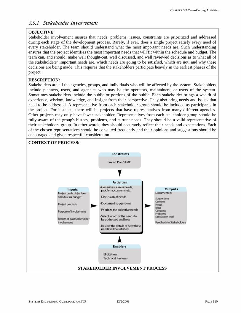
CHAPTER 3.9 Cross-Cutting Activities
SYSTEMS ENGINEERING GUIDEBOOK FOR ITS 12/2/2009 PAGE 110
3.9.1 Stakeholder Involvement
OBJECTIVE: Stakeholder involvement insures that needs, problems, issues, constraints are prioritized and addressed during each stage of the development process. Rarely, if ever, does a single project satisfy every need of every stakeholder. The team should understand what the most important needs are. Such understanding ensures that the project identifies the most important needs that will fit within the schedule and budget. The team can, and should, make well thought-out, well discussed, and well reviewed decisions as to what all of the stakeholders’ important needs are, which needs are going to be satisfied, which are not; and why these decisions are being made. This requires that the stakeholders participate heavily in the earliest phases of the project.
DESCRIPTION: Stakeholders are all the agencies, groups, and individuals who will be affected by the system. Stakeholders include planners, users, and agencies who may be the operators, maintainers, or users of the system. Sometimes stakeholders include the public or portions of the public. Each stakeholder brings a wealth of experience, wisdom, knowledge, and insight from their perspective. They also bring needs and issues that need to be addressed. A representative from each stakeholder group should be included as participants in the project. For instance, there will be projects that have representatives from many different agencies. Other projects may only have fewer stakeholder. Representatives from each stakeholder group should be fully aware of the group's history, problems, and current needs. They should be a valid representative of their stakeholders group. In other words, they should accurately reflect their needs and expectations. Each of the chosen representatives should be consulted frequently and their opinions and suggestions should be encouraged and given respectful consideration.
CONTEXT OF PROCESS:
STAKEHOLDER INVOLVEMENT PROCESS

CHAPTER 3.9 Cross-Cutting Activities
SYSTEMS ENGINEERING GUIDEBOOK FOR ITS 12/2/2009 PAGE 111
Inputs: Project Goals, Objectives, Schedule, and Budget [most recent version] provide an understanding of the environment of the project and the limits of time and money the project has remaining. Project’s major outputs to date [the most recent version] provide a view of what has already been decided. Purpose of involvement orients the stakeholder as to what the purpose of this particular session is. Results of past stakeholder involvement enables them to see the effects of previous stakeholder input, review what has been addressed, and how their efforts are helping both the stakeholder group and the project.
Control: Project Plan / SEMP defines the tasks, schedule, and processes to be employed for involving stakeholders.
Enablers: Elicitation provides techniques for gathering stakeholder input: constructive brainstorming, discussion, understanding, suggestions, and ideas. Technical Reviews provide a formalized setting for stakeholders to see what the outcomes of their inputs have been so far, and for ensuring that the most important concerns have been addressed.
Outputs: Documentation of stakeholders suggestions, opinions, needs, ideas, concerns, problems, satisfaction level includes recording all stakeholders ideas voiced during the session, re-writing them to make it clear and easy to understand, adding summary diagrams, lists and text, and describing how they affect the project. Feedback tells stakeholders and other project staff what new information and insight was revealed.
Process Activities: [Have stakeholders participate in] Generating and assessing lists of needs, problems, and concerns Candidate lists of needs, problems, concerns, issues, and constraints are developed first by the core team of the project. These lists are then reviewed by stakeholders, first one-on-one, and later in a group, so that stakeholders can add any missing items important to the groups they represent. Then have each stakeholder make an assessment of a number of characteristics [e.g. cost, risk, utility, importance] for each item on the list, from the stakeholder group’s point of view. Discussing the needs of all the stakeholders with all the other stakeholders This will enable each stakeholder to see these items as perceived by other stakeholders. It will enable the group to appreciate the needs and problems of other stakeholders, to understand where there are both synergistic and conflicting needs/solutions between different groups, and break down institutional barriers. Making suggestions on how the most vital needs of all the stakeholders can be satisfied most cost-effectively This will enable each stakeholder to benefit from the wisdom and experience of other stakeholders to help resolve conflicts and suggest solutions that can bring the greatest benefit to all the stakeholders as a group. Prioritizing the collective needs of all the stakeholders This will enable stakeholders to have a say in the prioritization process, to observe and influence what is selected, and to ensure that the stakeholder group is adequately represented during the process. It will also enable them to tell the rest of the stakeholder group how items were assessed, and prioritized. Selecting which needs will be addressed and how they will be addressed This will enable stakeholders to influence the selection process and understand thoroughly how and why the project solutions evolved. Reviewing the details of how these needs will be satisfied at each stage of the project As the project evolves, stakeholders should review how the stakeholders’ needs and problems are being addressed so they can help the project team abort any faulty solutions, mitigate risks, fine-tune solutions, and improve the utility and cost-effectiveness of the system.

CHAPTER 3.9 Cross-Cutting Activities
SYSTEMS ENGINEERING GUIDEBOOK FOR ITS 12/2/2009 PAGE 112
Where does Stakeholder Involvement take place in the project timeline?
Is there a policy or standard that talks about Stakeholder Involvement? FHWA Final Rule requires identifying the roles and responsibilities of participating agencies and stakeholders in the operation and implementation of ITS projects funded with Federal money from the Highway Trust Fund, including the Mass Transit Account. Which activities are critical for the system’s owner to do? Identifying who the stakeholder groups are Getting the appropriate person[s] to represent
each important stakeholder group [These “stakeholder representatives” become part of the development team and participate in the stakeholder involvement sessions]
Ensuring that stakeholder ideas, opinions, needs, and concerns are used to decide what needs the system will address, how the system will address them, and ensure the resulting product gives the highest benefit to the stakeholders for the time and budget allowed
How do I fit these activities to my project? [Tailoring] Some projects naturally involve more stakeholder groups than others. The more stakeholder groups there are, the more stakeholder-group involvement sessions will be necessary to build consensus. Some projects are quite similar to previous projects. Other projects are not similar to anything
that has been done before. In general, the higher the similarity to previous successful projects, the less time and scrutiny will be needed from the stakeholders. The more the intended system differs from anything previously done, the more input will be need from the stakeholders. What should I track in this process step to reduce project risks and get what is expected? [Metrics] On the project management side: % of stakeholder involvement activities that
occurred on time and within budget [as compared with the project plan]
% of stakeholder groups represented in each stakeholder-involvement activity
Level of satisfaction of each stakeholder group [as reported by its representative] with the decisions, plans, and processes to date
For each stakeholder group, % of the critical needs, problems, issues, and concerns addressed
Level of satisfaction of each stakeholder group that their critical needs, problems, concerns, and issues have been adequately addressed at each point in the project
Checklist: Are all the bases covered? Are all of the stakeholder groups identified for
the project and is at least one stakeholder representative identified for each group?

CHAPTER 3.9.1 STAKEHOLDER INVOLVEMENT
SYSTEMS ENGINEERING GUIDEBOOK FOR ITS 12/2/2009 PAGE 113
Has the project’s goals, objectives, schedule, and budget been discussed with each stakeholder’s representative and have all the questions been addressed?
Has each stakeholder’s representative been informed as to why stakeholder involvement is critical to the success of the project?
Has each stakeholder’s representative been informed as to who all the other stakeholder groups are that are planning to be involved, and why each are involved?
Has it been demonstrated to each stakeholder’s representative how their participation will benefit the stakeholder group they represent?
Has it been explained to each stakeholder’s representative how past stakeholder participation has affected the project? How it has improved it? Changed it? What the results were of past involvement?
Has it been described to each stakeholder’s representative what is needed from them [both now and in the long-term]?
Has each stakeholder representative been asked for feedback? Were their needs, ideas, and concerns documented as they relate to the project?
Has all of the stakeholder’s representatives’ feedback been utilized in developing and prioritizing the needs, concerns, issues, and alternative solutions?
Has all of the stakeholder’s representatives’ feedback been utilized at each point in the project’s development?
Have all the stakeholder’s representative’s questions been answered?
Has each stakeholder representative’s satisfaction level been assessed with the project processes, plans, and decisions to date?
Has each stakeholder representative been provided with feedback on the results of the stakeholder-involvement activities?
Has appreciation for each stakeholder representative’s time, energy, and ideas been expressed after each stakeholder involvement session?
Are there any other recommendations that can help? A Closer look at stakeholders
There are often many levels of Stakeholders.
Primary stakeholders are those who have the biggest stake in project and usually, are those who will be operating, using, maintaining, and/or funding the system. For example, a Traffic Information System, [a system which collects and provides information on traffic conditions, accidents, alternative routes, weather, and road conditions that affect traffic], primary stakeholders would include each department of transportation [perhaps both state and local] that collects and/or uses this information to help improve safety and traffic flow. Other primary stakeholders would include the police and emergency services that use and provide information to the system. If there are private groups such as Information Service Providers who collect and disseminate part of this information, they, too, are stakeholders. There are also segments of the public who are stakeholders. They may include commuters, the handicapped & elderly, and commercial vehicle organizations. A given project may or may not have such segments of the public represented by a specific person. It may simply remember to explicitly identify and include the interests and needs of such users. Sometimes, surveys are used to assess the needs, problems, concerns, and issues of such segments of the public. Sometimes, organizations who service these segments of the public are queried. For instance, drivers of vehicles that transport the handicapped or the elderly may be queried. Another example, the Automobile Club [AAA] might be contacted to provide information on typical needs of the traveling motorists they service. Some projects may have as many as 20 or 30 stakeholder groups represented. [More than this number becomes unwieldy to use in discussion groups or workshops]. Some projects may have as few as 3 to 5 stakeholder groups. A closer look at the role the operating organization stakeholder is expected to perform.
It is these eventual operators, who have the most knowledge of the environment in which the system will operate; who have, or soon will have, the best opinions on how well
the system will help them do their job. Understanding of the operating domain is the first resource in designing the system. However, the operators’ deeper and more extensive understanding of the operating domain, tempered by their possibly limited understanding of the potential of the system, is a second resource

CHAPTER 3.9.1 STAKEHOLDER INVOLVEMENT
SYSTEMS ENGINEERING GUIDEBOOK FOR ITS 12/2/2009 PAGE 114
which must be used to validate the Concept of Operations and to develop the requirements of the system. Normally, when the above-described stakeholder involvement process is used conscientiously and thoroughly, the stakeholders naturally develop a sense of ownership and pride in the evolving system. In fact, many of the stakeholders will eventually become champions of the system. When a system truly helps the stakeholders with their most pressing problems and needs, stakeholders naturally will champion the system. The only way to make sure the system truly meets the most important needs of all the high-priority stakeholders is to have them provide the experience and knowledge base they each have, and to tap into their collective expertise and insight as to how to solve their common, and sometimes conflicting, needs. When soliciting feedback from stakeholders, whether it is regarding their needs, concerns, issues, or anything else, it is best to provide an initial set first based on previous elicitation techniques. Use this as a strawman that the stakeholders can modify. Many people draw a blank when simply asked “What are the needs?” Or, “what are the top priorities?” However, if their input is solicited by making up a list, they are likely to be able to give their opinion on how they should be changed. It is important to provide the leadership a vision that draws the stakeholders into participating and taking an interest in the project. Good leadership includes imparting the vision of the project: why it is needed how it will help solve current problems how it will benefit each of the stakeholder
groups Be interested in the stakeholder's needs, issues, problems, and suggestions. Demonstrate that this group of stakeholder representatives is vital to finding the greater good for the collection of stakeholder groups. Tell them that their input is needed. Give due respect to every piece of input and every suggestion they make. Encourage them to respect each other’s needs and problems. Be a good moderator: Give everyone a chance to express their
opinion, avoid petty side arguments and bickering
Make suggestions as a starting point.
Ask others for feedback on various suggestions
Brainstorm with the stakeholders Empathize with them Show them gratitude for their inputs, even if
many issues remain unresolved Keep the group on track, seeking solutions for
the project Keep the group informed on how their past
participation has helped the project, and on what their future participation will be
Provide them with survey and questionnaire results
Keep the discussions positive, avoid any destructive activities [blaming, shaming, put-downs, or insults.] when they occur
These actions will help achieve convergence [vs. divergence] of ideas and concepts. It will also help break down institutional barriers and aid stakeholders to work towards the greater good. Keep the interactions with the stakeholders regular, predictable, and ongoing throughout the project. Keeping in mind the vision issues delineated above. The initial contact with stakeholders may be via one-on-one sessions. Explain the project vision to them and help them identify the appropriate person so that their agency’s needs and issues are adequately addressed. Workshops should be included where all the stakeholder representatives interact with each other. When the program schedule is set, include such stakeholder sessions at regular and pre-scheduled intervals. A series of interactive sessions early in the project will be needed to make sure important needs, issues, problems, and concerns are identified. Have them help in prioritizing these needs. Surveys and questionnaires can be used to support these activities. Provide feedback on the results of these surveys and questionnaires. Stakeholder help will be needed in identifying alternative candidate solutions and in pointing out the pros and cons of each solution. Once the initial set of needs and alternatives has been clearly identified, discussed, and evaluated, continued feedback will be needed on how these are being used to flesh out the details on the evolving system. It is critical that they review all the major decisions, prioritizations, and evolving designs of the system and its interfaces. Point out what elements they feel are satisfactory and where improvements are needed.

CHAPTER 3.9.2 ELICITATION
SYSTEMS ENGINEERING GUIDEBOOK FOR ITS 12/2/2009 PAGE 115
3.9.2 Elicitation
OBJECTIVE: Elicitation is a set of techniques for drawing out stakeholder needs, goals, requirements, constraints, priorities, normal operations, and preferences. It is done early in system development to support the initial needs assessment leading to the development of requirements. As the project progresses, the process is revisited as necessary to provide further clarification.
DESCRIPTION: Elicitation is a collection of techniques to draw out and clarify stakeholder needs and requirements. Multiple techniques are provided to address the needs from various directions. Needs are usually vague, implicit [unstated], or described in terms of technical solutions. Elicitation techniques help the stakeholders clarify their needs. The techniques present a logical sequence, starting with available material and build on what is learned through additional feedback. The actual steps taken depend upon the size and complexity of the project. Other factors include the number and diversity of the stakeholders.
CONTEXT OF PROCESS:
ELICITATION PROCESS
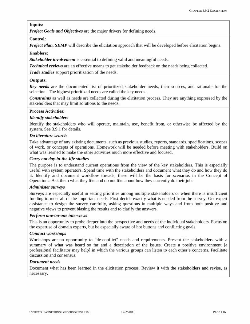
CHAPTER 3.9.2 ELICITATION
SYSTEMS ENGINEERING GUIDEBOOK FOR ITS 12/2/2009 PAGE 116
Inputs: Project Goals and Objectives are the major drivers for defining needs.
Control: Project Plan, SEMP will describe the elicitation approach that will be developed before elicitation begins.
Enablers: Stakeholder involvement is essential to defining valid and meaningful needs. Technical reviews are an effective means to get stakeholder feedback on the needs being collected. Trade studies support prioritization of the needs.
Outputs: Key needs are the documented list of prioritized stakeholder needs, their sources, and rationale for the selection. The highest prioritized needs are called the key needs. Constraints as well as needs are collected during the elicitation process. They are anything expressed by the stakeholders that may limit solutions to the needs.
Process Activities: Identify stakeholders Identify the stakeholders who will operate, maintain, use, benefit from, or otherwise be affected by the system. See 3.9.1 for details. Do literature search Take advantage of any existing documents, such as previous studies, reports, standards, specifications, scopes of work, or concepts of operations. Homework will be needed before meeting with stakeholders. Build on what was learned to make the other activities much more effective and focused. Carry out day-in-the-life studies The purpose is to understand current operations from the view of the key stakeholders. This is especially useful with system operators. Spend time with the stakeholders and document what they do and how they do it. Identify and document workflow threads; these will be the basis for scenarios in the Concept of Operations. Ask them what they like and do not like about how they currently do their job. Administer surveys Surveys are especially useful in setting priorities among multiple stakeholders or when there is insufficient funding to meet all of the important needs. First decide exactly what is needed from the survey. Get expert assistance to design the survey carefully, asking questions in multiple ways and from both positive and negative views to prevent biasing the results and to clarify the answers. Perform one-on-one interviews This is an opportunity to probe deeper into the perspective and needs of the individual stakeholders. Focus on the expertise of domain experts, but be especially aware of hot buttons and conflicting goals. Conduct workshops Workshops are an opportunity to “de-conflict” needs and requirements. Present the stakeholders with a summary of what was heard so far and a description of the issues. Create a positive environment [a professional facilitator may help] in which the various groups can listen to each other’s concerns. Facilitate discussion and consensus. Document needs Document what has been learned in the elicitation process. Review it with the stakeholders and revise, as necessary.

CHAPTER 3.9.2 ELICITATION
SYSTEMS ENGINEERING GUIDEBOOK FOR ITS 12/2/2009 PAGE 117
Where does elicitation take place in the project timeline?
Is there a policy or standard which includes Elicitation? FHWA Final Rule does not specifically mention general elicitation practices to be followed. CMMI provides some useful material in this area. Which activities are critical for the system’s owner to do? Identify stakeholders and encourage their
participation Participate as stakeholders in elicitation
activities Review the summaries and conclusions of the
elicitation process How do I fit these activities to my project? [Tailoring] All projects require an identification of the stakeholders and documentation and acceptance of the findings. Beyond that, the combination of techniques used depends on the complexity of the system under development. A small, straight-forward system may only require a literature search. This is especially true if the needs have been well thought out and described in a document. Even in that case, an informal one-on-one interview is helpful to clarify the document. A day-in-the-life study is important when the system will change operations. Or, if it is being developed to enhance operations. Surveys are needed to set priorities in systems with vague or contentious needs or an insufficient budget. One-on-one interviews are always recommended.
Elicitation is more important for more complex projects. For example, if new detector technology is to be installed, it is useful to talk to experts in that technology. Speak with people at other agencies who have used the technology. Workshops may be as simple as a presentation with feedback. They are essential when there are multiple agencies involved, especially if they have not worked together previously. What should I track in this process step to reduce project risks and get what is expected? [Metrics] On the Project management side: Percentage of relevant documents which have
been utilized Percentage of stakeholder groups/individuals
who have been queried using at least one of the techniques
Number of stakeholders who have agreed to the conclusions of the elicitation process
Checklist: Are all the bases covered? Have all relevant stakeholders been
identified? Has the stakeholder equity into the system
been defined? Have all appropriate techniques been used to
draw out needs and requirements? Have all assumed needs been uncovered? Have all stakeholders agreed with the
conclusions?

CHAPTER 3.9.2 ELICITATION
SYSTEMS ENGINEERING GUIDEBOOK FOR ITS 12/2/2009 PAGE 118
Are there any other recommendations that can help? A professional facilitator will
help to elicit needs, especially if there are conflicting needs. Also, there are techniques for collecting, analyzing, and prioritizing needs. For example, a workshop techniques like the ten dollar technique where stakeholders are given ten (1 dollar tokens) and asked to spread the tokens over a set of twenty needs. This forces the stakeholders to make priority choices among the twenty needs. Any collected needs must be tempered by reality. As needs are collected, be aware of potential cost overruns, risks, conflicts, or scope creep. Here are some metrics to keep in mind and in front of the stakeholders. Estimated cost of meeting the expressed needs
or requirements Estimated risk level of the expressed needs or
requirements Number of expressed needs that conflict with
those expressed by other stakeholders Number of new requirements that are beyond
the initial needs statement, since they signal a risk of scope creep
Do not accept stated needs at face value without some exploration. Initial needs are often expressed in terms of solutions. For example, a
need for more loops is really a need for better traffic information. Focus on the underlying need. Often, a key need is not expressed because it seems obvious. Explore some alternative solutions to uncover unstated assumptions. There is an art to eliciting needs. It involves repeated digging and probing. Ask what they need. Then, ask why they need it. Whatever their answer, ask them, “Why?” Continue until a complete understanding is obtained as to what it is they really need and why. A closer look at a useful tool “what if?” Ask them to consider alternative system approaches. Ask them about alternative technologies, such as cameras rather than loops, or alternative operations, such as local rather than centralized monitoring. This gets at underlying unspoken assumptions, requirements, or constraints. Sometimes the stated need is expressed in terms of a familiar solution. For example, the use of the Windows operating system may be cited. Does that mean an otherwise good Unix-based traffic
management system is unacceptable? These types of questions ferret out the real requirements and bring previously unstated constraints to light. When developing requirements for the system, it is helpful to get someone who is not closely associated with the system that can think outside the box and probe in ways that can help clarify the needs and requirements. What are sources for a literature search? This varies greatly from project to project and depends on where in the development process the search is being done. If there is a contract that includes a scope of work, that will be a prime source. If the Concept of Operations has been completed, it will cover needs. Any applicable standards/specifications should be consulted. There may be previous studies for this or neighboring agencies. Other reports, such as strategic plans, will contain information on needs. If multiple agencies are involved, it is essential to understand all such documents. Suggestions for day-in-the-life studies If possible, watch them as they perform their jobs. Make note of the sequence of actions [as the basis for scenarios in the Concept of Operations]. Then, ask them about unusual situations such as failure events and how they handle them. Suggestions for administering surveys The Agency may regularly perform surveys. Take advantage of their experience. In fact, they are a good source of inputs from the traveling public, the ultimate stakeholder. Suggestions for one-on-one interviews At this point, a description of the needs should have been documented. This is an excellent starting point for discussions. Do they disagree with any of them? Are there any constraints that they know of which would make it difficult to meet the stated needs? Was anything important left out? Suggestions for workshops So far, needs have been gathered from individuals. Especially when working with multiple agencies, there may be very different priorities and even conflicting needs. For example, a transit agency wants signal priority for its buses. The agency that operates the roads thinks that it would be too disruptive of traffic flow. The workshop can be used to get the stakeholders together to listen to each other and to come to an agreement. Maintain an atmosphere that encourages this kind of dialog.

CHAPTER 3.9.3 PROJECT MANAGEMENT PRACTICES
SYSTEMS ENGINEERING GUIDEBOOK FOR ITS 12/2/2009 PAGE 119
3.9.3 Project Management Practices
OBJECTIVE: Project management plans will document how to manage resources, monitor, and take action during project activities and tasks so that the goals and objectives of the project are met. Project management practices will plan, execute, monitor, intervene, and learn from the project activities of each project participant with the goal of completing all project objectives on time, within budget, and to stakeholder satisfaction.
DESCRIPTION: Project management includes the following practices: Plan coordination with all project participants, develops and documents the project’s plan [task
description, budget, and schedule] for all necessary project activities Execute plans and actions, coordinating people and other resources to carry out the project’s activities Monitor results to measure the progress of each project activity according to the plan Intervene in the execution of an activity to ensure that it continues to support the overall progress of the
project Communicate to the project team, the goals, objectives, and vision of the project. Learn from results and adjust project management practices based on the experience of previous tasks Effective communication [written, in meetings, and with individual participants] is key to ensuring that project participants are sharing their objectives, status, problems, and fixes. Good project management practices must be married with good management skills. These skills include leading [establishing direction, aligning people to that direction and motivating people to overcome obstacles], communicating and stimulating communications among others, negotiating with others on what they need to do, and problem solving with the personnel performing the activity and with their management.
PROJECT MANAGEMENT PRACTICES
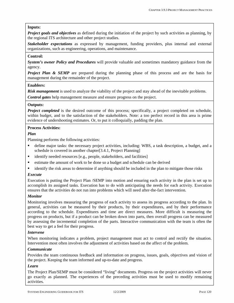
CHAPTER 3.9.3 PROJECT MANAGEMENT PRACTICES
SYSTEMS ENGINEERING GUIDEBOOK FOR ITS 12/2/2009 PAGE 120
Inputs: Project goals and objectives as defined during the initiation of the project by such activities as planning, by the regional ITS architecture and other project studies. Stakeholder expectations as expressed by management, funding providers, plus internal and external organizations, such as engineering, operations, and maintenance.
Control: System’s owner Policy and Procedures will provide valuable and sometimes mandatory guidance from the agency. Project Plan & SEMP are prepared during the planning phase of this process and are the basis for management during the remainder of the project.
Enablers: Risk management is used to analyze the viability of the project and stay ahead of the inevitable problems. Control gates help management measure and ensure progress on the project.
Outputs: Project completed is the desired outcome of this process; specifically, a project completed on schedule, within budget, and to the satisfaction of the stakeholders. Note: a too perfect record in this area is prime evidence of undershooting estimates. Or, to put it colloquially, padding the plan.
Process Activities: Plan Planning performs the following activities: define major tasks: the necessary project activities, including: WBS, a task description, a budget, and a
schedule is covered in another chapter[3.4.1, Project Planning] identify needed resources [e.g., people, stakeholders, and facilities] estimate the amount of work to be done so a budget and schedule can be derived identify the risk areas to determine if anything should be included in the plan to mitigate those risks Execute Execution is putting the Project Plan /SEMP into motion and ensuring each activity in the plan is set up to accomplish its assigned tasks. Execution has to do with anticipating the needs for each activity. Execution ensures that the activities do not run into problems which will need after-the-fact intervention. Monitor Monitoring involves measuring the progress of each activity to assess its progress according to the plan. In general, activities can be measured by their products, by their expenditures, and by their performance according to the schedule. Expenditures and time are direct measures. More difficult is measuring the progress on products, but if a product can be broken down into parts, then overall progress can be measured by assessing the incremental completion of the parts. Interactive communication with the team is often the best way to get a feel for their progress. Intervene When monitoring indicates a problem, project management must act to control and rectify the situation. Intervention most often involves the adjustment of activities based on the affect of the problem. Communicate Provides the team continuous feedback and information on progress, issues, goals, objectives and vision of the project. Keeping the team informed and up-to-date and progress. Learn The Project Plan/SEMP must be considered “living” documents. Progress on the project activities will never go exactly as planned. The experiences of the preceding activities must be used to modify remaining activities.

CHAPTER 3.9.3 PROJECT MANAGEMENT PRACTICES
SYSTEMS ENGINEERING GUIDEBOOK FOR ITS 12/2/2009 PAGE 121
Where does Project Management take place in the project timeline?
Is there a policy or standard which includes Project Management? [Reference: PMI: BOK] FHWA Final Rule does not specifically mention general project management practices to be followed. CMMI and PMI provide best practices in this area. Which activities are critical for the system’s owner to do? In general, project management cannot be delegated to others. Of course, contractors will be required to have their own project management [which must be defined in their own Project Plan or equivalent]. Even then the system’s owner must still manage the activities of the contractor. Major project management activities include: Planning of all project activities along with
task description, performing, organization, budget, and schedule
Facilitating the execution of each activity, especially by ensuring that all inputs are available and sufficient
Facilitating the execution of each activity by maintaining open communications between project management, and the performing organization of related activities
Monitoring the execution of each activity and intervening in that execution if necessary
Modifying not only the schedule and budget but the very processes of each activity based on the success of previous activities and encountered risks
How do I fit these activities to my project? [Tailoring] Project planning is one of the most highly tailored of all the project processes. In fact, the purpose of the planning step is to tailor the agency’s project management practices to the specifics of the project. It is not uncommon for newer project managers to either over-plan or under-plan their project. With experience, it will become easier to develop project plans that are commensurate to the scope of the project. A plan that matches the scope will also maximize the usefulness of the information contained in the plan. A few guidelines are: Some activities will be routine to the
personnel performing the activity and some will be new. In general, it is best to use existing and familiar processes for the routine activities because the organization will be more comfortable and more efficient doing things the way they always have. For instance, an organization may have their customary processes for managing configuration control of their products. It is generally better to let them use those familiar processes than trying to force them to use new techniques or tools of dubious value. Of course, project management must make sure they will do configuration management when it is necessary. Utilization of tools/techniques SME and a change agent is advised here

CHAPTER 3.9.3 PROJECT MANAGEMENT PRACTICES
SYSTEMS ENGINEERING GUIDEBOOK FOR ITS 12/2/2009 PAGE 122
The need for detail in the project’s plan will increase for activities that involve or impact larger numbers of people, especially people from different organizations with different management structures. For a small team of only a few people, the need for detail of the processes in the plan can be minimal, as long as they understand the products they must produce
One area not to skimp on is detail on the deliverables of an activity. These need to be clear to the personnel performing the activity
The activities covered in the Project Plan/SEMP must align to the technical scope of the project. For ITS, this is especially true for projects needing custom software development. Ensure the plan is developed by people who have experience with the processes needed for each type of product. If the product is software code, software engineers must be involved in the planning
In preparing the project schedule, a careful analysis of each activity’s outputs and inputs is necessary to refine the sequence of the activities. Obviously, if an activity needs a certain input, it must be an output from some previous task. However, it is often possible to initiate an activity before a needed output of another activity is completely finished. In addition to the inevitable start-up tasks, experienced personnel can judge what parts of the previous activity are solid enough to work with
A Work Breakdown Structure [see Chapter 3.4.1] is a very useful project management tool to ensure that all tasks have been identified
What should I track in this process step to reduce project risks and get what is expected? [Metrics] On the technical side: Progress in the preparation of activity deliverables and the analysis needed to prepare those deliverables On the project management side: Budget expenditure profiles and the
relationship between work accomplished and budget expended
Task schedules and the similar relationship between work accomplished and time expended
Checklist: Are all the bases covered? Are the project’s goals and objectives clear?
Are they defined sufficiently to support project planning?
Are the task descriptions, as well as the identification of inputs and outputs prepared for the project activities?
Are the task descriptions, as well as the cost and time estimates being prepared by people familiar with the underlying processes?
Are the task descriptions, budget, and schedule accepted by the performing organizations?
Do the financial tracking processes provide accurate and timely information on team expenditures?
Are regular, periodic [usually weekly] meetings being held with each active task team?
Do these meetings review progress on the activity by looking at the preparation of products [outputs], expenditures, and progress relative to the schedule?
When a problem is encountered, are intervening actions done in a timely and effective manner?

CHAPTER 3.9.4 RISK MANAGEMENT
SYSTEMS ENGINEERING GUIDEBOOK FOR ITS 12/2/2009 PAGE 123
3.9.4 Risk Management
OBJECTIVE: Risk management achieves a proper balance between risk and reward. It seeks to understand and avoid the potential cost, schedule, and performance risks to a project. It takes a proactive and well-planned role in anticipating problems and responding to them if they occur. There are uncertainties involved in any project. The only certainty is that, in at least some small way, things will not go as planned. Risk management anticipates and controls these risks.
DESCRIPTION: Risk management starts early in the project, by identifying the full range of potential risks. Analysis selects the most critical ones to mitigate or to plan for. The process continues throughout the project with the monitoring of these potential risks and a well-planned response to correct problems as they occur.
CONTEXT OF PROCESS:
RISK MANAGEMENT PROCESS

CHAPTER 3.9.4 RISK MANAGEMENT
SYSTEMS ENGINEERING GUIDEBOOK FOR ITS 12/2/2009 PAGE 124
Inputs: Project Plan needs to be examined for potential risks. Goals and objectives drive the assignment of prioritizing risks. Control: SEMP defines the systems engineering process. Enablers: Stakeholder involvement and outside experts and help identify and prioritize risks. Program metrics are used for tracking risks. Decision gates are structured opportunities to check risk levels and mitigate risk. Outputs: Risk Management Plan is the plan on how risk management will be performed. Risk Matrix is the graphical representation of the relative probability and consequence of each risk. Risk data may also be represented in tabular form. High priority risks are the most important risks to monitor. Risk monitoring is the ongoing process of tracking symptoms of risks. Risk management is the ongoing process for correcting any impending problems. The process may use descriptive and inferential, parametric and non-parametric techniques. Process Activities: Plan Risk Management Develop a risk management plan as part of the Project plan/SEMP. The plan should include risk assessment, mitigation, and resolution approaches for the project. Identify potential risks Stakeholders, project participants, and outside experts first brainstorm to identify potential risks to project's success. These should cover all possible obstacles. It is important to get a broad sample of inputs, since the team faces the greatest risks in areas in which they are not familiar. [See the checklist below for potential risk areas.] Collect “lessons learned” from previous projects to help identify potential risks. Assess risks There are two components to risk: the likelihood that an undesirable event will occur and the consequences if it does occur. Likelihood is expressed quantitatively [as a probability percentage] or qualitatively [in terms of categories, such as likely, probable, improbable, and impossible]. Consequences may be expressed quantitatively, in terms of dollars or performance metrics, or qualitatively, in terms of categories, such as catastrophic, critical, marginal, and negligible. Analyze and prioritize risks Risk is the expected value of a potential loss, based on reasoning under uncertainty. Qualitatively, risk is represented by positions in a risk matrix. The risk matrix is useful in both types of analysis. The columns represent the likelihood, and the rows the consequences. Anything that falls in or near the “likely/catastrophic” box is high risk. Start in that corner and select the top risks of concern. [See Tip below] Define approaches to handling the top risks Identify and evaluate alternatives for handling the top risks. Before the monitoring indicates a problem, there are steps that can be taken to control the high-priority risks, such as: changing things to eliminate them, reducing their likelihood, or reducing their impact. One example is eliminating requirements that carry a high risk but are of marginal value. Another is parallel development. Plan contingencies for the remaining highest priority risks before starting. Then, monitor them regularly. Monitor risks Identify metrics for each of the selected top risks. As a management tool, these are the triggers that release contingency funds to address a problem. These metrics must be easy to track and signal a potential or imminent problem. Cost and schedule are always risks. Their metrics are spending and performance to schedule [see 3.8.5]. Set up a schedule and procedure to track the metrics on a regular basis. Respond per plan, if necessary If the monitoring indicates a problem, responses should performed quickly, since there is a plan in place. This avoids the common problem of poor decisions and project redirections under the pressure of the moment.

CHAPTER 3.9.4 RISK MANAGEMENT
SYSTEMS ENGINEERING GUIDEBOOK FOR ITS 12/2/2009 PAGE 125
Where does risk management take place in the project timeline?
Is there a policy or standard that talks about Risk Management? FHWA Final Rule does not specifically mention general risk management practices to be followed. CMMI provides some best practices in this area. Which activities are critical for the system’s owner to do? Participate in risk identification Review and approve the identified key risks Ensure ongoing risk monitoring Participate in mitigation activities Lead the development of the risk plan How do I fit these activities to my project? [Tailoring] The level of each activity should be appropriately scaled to the size of the project. For example, a small project may consider only a few risks and prioritize them qualitatively. The level of intensity of monitoring and mitigation should be appropriate for the project risk. A project that is technically and organizationally similar to previous ones may need only to monitor cost and schedule. What should I track in this process step to reduce project risks and get what is expected? [Metrics] On the technical side: Number of potential risks in each of the
higher risk categories [e.g., frequent/catastrophic]
Risk monitoring metrics as established in each step
On the project management side: Completion of documentation of risks and
their priorities Number of high priority risks with a
documented resolution plan Checklist: Are all the bases covered? Is the risk management plan included in the
Project Plan/SEMP? Have all sources of risks been identified?
- Technical [e.g., new detectors do not perform as expected]
- Institutional [e.g., agency data sharing, new regulations, public opposition]
- Funding [delays or cuts] - Environmental [e.g., temperature levels for
outdoor field equipment, restrictions on building]
- Personnel [e.g., loss of key personnel, substandard performance]
- Commercial [e.g., vendor does not deliver COTS product]
Were experts and stakeholders queried in all the areas of risk to develop a broad list of credible risks?
Are the risks prioritized and the most critical ones identified?
For each high priority risk, are there ways to eliminate the risk? Or, reduce its likelihood and/or impact?

CHAPTER 3.9.4 RISK MANAGEMENT
SYSTEMS ENGINEERING GUIDEBOOK FOR ITS 12/2/2009 PAGE 126
For each high priority risk, have the symptoms of the problem and a means for monitoring them been identified?
Are the high priority risks regularly monitored throughout the project?
For each high priority risk, is there a risk resolution plan?
Are there any other recommendations that can help? All useful systems incur some risk. The goal is a balance between system performance and risk. That is why the focus is on only the most critical risks. Lesser risks will and should be accepted. From a management viewpoint, there are four ways to handle risk. 1] Mitigate the risk by allocating contingency funds to its resolution if it becomes necessary 2] Accept a risk that cannot realistically be mitigated, such as an earthquake 3] Avoid the risk by changing the requirements or design 4] Transfer the risk [e.g., to an insurance company or to a developer under a fixed price contract]. Even if a dedicated risk management team is in-place, everyone on the team must be encouraged to identify potential risks. A “shoot the messenger” atmosphere will only allow hidden risks to grow out of control. Uncertainty is what makes risk management both difficult and essential. There are statistical techniques such as probabilistic decision theory for reasoning under uncertainty. The most basic technique is expected value. Risk is computed as the probability of occurrence multiplied by the consequence of the outcome. Probability is between 0 [minimal] and 1 [certain]. Consequence is expressed in terms of dollars, features, or schedule. Multiplying probability of occurrence and consequence [impact analysis] together gives a risk assessment value between 0 [no risk] and 1 [definite and catastrophic].
When exact data is not available for expected costs and probabilities. One can get reasonably good results simply by rating risks qualitatively relative in
three to five categories in each of impact and likelihood. Below is an example of the matrix used for such an evaluation. The numbers are the order in which the risks are to be considered. Anything that is in the box labeled “1” is the highest priority. In fact, any risk that is both catastrophic and likely indicates a serious system
problem requiring a change in requirements or design.
Likely 0.7-1.0
Probable 0.4 to 0.7
Improbable 0.0 to 0.4
Impossible 0
Catastrophic 0.9 to 1.0
1 3 6
Critical 0.7 to 0.9
2 4 8
Marginal 0.4 to 0.7
5 7 10
Negligible 0 to 0.4
9 11 12
A closer look at definitions and examples of consequence and probability ratings
Here are definitions to firm up the consequence levels used in the matrix [from INCOSE Systems Engineering Handbook]. Here the “mission” is the purpose of the system such as traffic management. Catastrophic: Failure would result in project failure meaning a significant degradation/non-achievement of technical performance. Critical: Failure would degrade system performance to a point where project success is questionable, for example: a reduction in technical performance. Marginal: Failure would result in degradation of secondary system functions, a minimal to small reduction in technical performance. Negligible: Failure would create inconvenience or non-operational impact. No reduction in technical performance. Here are examples of some of the characteristics that would impact the probability of failure [adapted from INCOSE Systems Engineering Handbook]. Maturity: Existing system, probability is 0.1 Minor redesign, 0.3 Major change [feasible], 0.5 Complex design [technology available], 0.7 State of the art [some research done] 0.9 Complexity: Simple design, 0.1 Minor increase in complexity, 0.3 Moderate increase in complexity, 0.5 Significant increase in complexity, 0.7 Extremely complex, 0.9 Note that if there are multiple risks. The overall probability will be at least as high as the highest of them. Often it will be even higher.
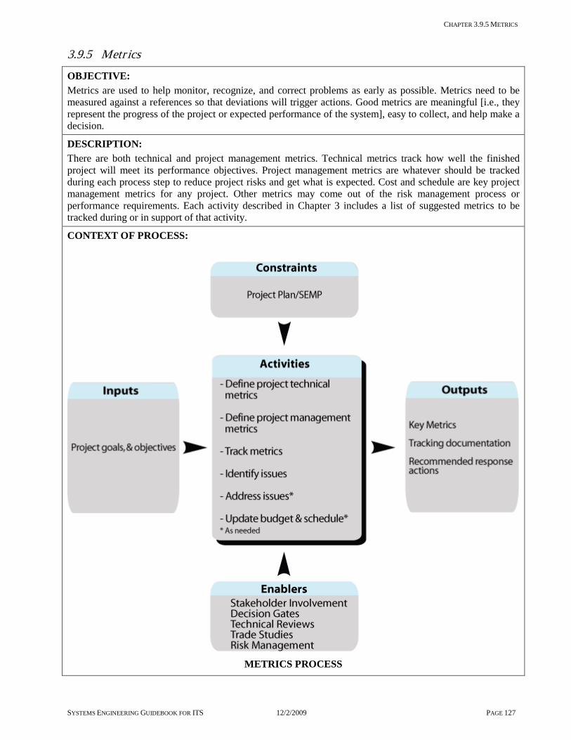
CHAPTER 3.9.5 METRICS
SYSTEMS ENGINEERING GUIDEBOOK FOR ITS 12/2/2009 PAGE 127
3.9.5 Metr ics
OBJECTIVE: Metrics are used to help monitor, recognize, and correct problems as early as possible. Metrics need to be measured against a references so that deviations will trigger actions. Good metrics are meaningful [i.e., they represent the progress of the project or expected performance of the system], easy to collect, and help make a decision.
DESCRIPTION: There are both technical and project management metrics. Technical metrics track how well the finished project will meet its performance objectives. Project management metrics are whatever should be tracked during each process step to reduce project risks and get what is expected. Cost and schedule are key project management metrics for any project. Other metrics may come out of the risk management process or performance requirements. Each activity described in Chapter 3 includes a list of suggested metrics to be tracked during or in support of that activity.
CONTEXT OF PROCESS:
METRICS PROCESS

CHAPTER 3.9.5 METRICS
SYSTEMS ENGINEERING GUIDEBOOK FOR ITS 12/2/2009 PAGE 128
Inputs: Goals and objectives define direction, priorities, and change of course, if necessary. Metrics for project phase are defined by each project step to check its progress. Control: SEMP provides guidance for the systems engineering process. Schedule and Budget constrain the project. Enablers: Stakeholder involvement enables the stakeholders to suggest metrics and provide guidance. Control gates provide an opportunity for tracking progress. Risk management suggests and uses metrics. Outputs: Metrics are the selected measures of project progress and performance. Tracking documentation is a history of project progress relative to the metrics. Recommended response actions to noted project problems document the recourse and rationale. Technical reviews suggest metrics and review their tracking. Trade studies compare alternatives relative to the metrics. Process Activities: Define technical metrics Technical metrics track the expected performance and effectiveness of the system being developed. These are related to the system mission. They often address critical performance parameters such as response time or accuracy. An example is the time to compose an Amber Alert message and get it displayed on CMS system-wide, since this must be done within 15 minutes. A Technical metrics topic [What should I track in this process step to reduce project risks and get what is expected?] is included in each chapter that related to the task. Define project management metrics Project management metrics track progress. Define metrics that indicate a potential problem. These, then, act as triggers for risk management. Each step of the systems engineering process has metrics associated with it. Each task in Chapter 3 includes a list of project-related metrics specific to that task. These give an indication of how far along the task is. For example, Concept Exploration has metrics for the percentage of candidate concepts evaluated and the percentage of stakeholders who have approved the study. In some cases the metrics will simply be whether or not something has been completed. There are other metrics related to milestones or to how much has been developed or delivered, such as the number of subroutines written or the lane-miles instrumented. Appropriate milestones should be meaningful and easy to track. Spending to date is always an essential metric. Track metrics Progress on the milestones and status of metrics relative to cost and schedule is compared regularly with the expected progress. A simple way to do this is to plot the metric relative to dollars spent. The best estimate of where the project will end up comes from extrapolating the line out to the end. This is because, despite all efforts to “catch up,” projects that are behind tend to continue to fall behind by the same percentage. Identify problems If any of the metrics indicate a potential problem, use them to trace back to the source of concern. A fast and decisive response is necessary to get a project back on track. Asking the right questions will suggest what action to take. Are there any problems that are hindering development? Do we have the right resources? Is the budget realistic? Is the schedule realistic? Is the scope overly ambitious? Fix problems Make sure personnel are properly assigned and well used. Eliminate any efforts which do not trace back to the requirements, and are therefore unnecessary. Modify budget, schedule, or scope Sometimes project plans are overly optimistic. If everything possible to streamline the project and solve problems has been done, it may be that the scope of work cannot be completed within the time and budget allocated. Sometimes hard decisions need to be made, and will only get worse if delayed. Consider eliminating requirements of marginal value, extending the schedule, or asking for more budget. This is extremely disruptive, and should be avoided if at all possible. Ideally, the project plan is carefully and realistically developed up front, so that these types of changes are avoided.
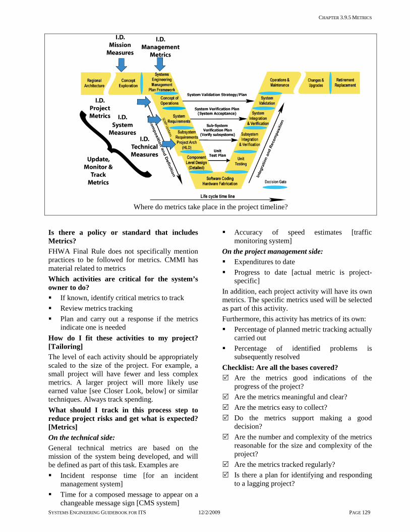
CHAPTER 3.9.5 METRICS
SYSTEMS ENGINEERING GUIDEBOOK FOR ITS 12/2/2009 PAGE 129
Where do metrics take place in the project timeline?
Is there a policy or standard that includes Metrics? FHWA Final Rule does not specifically mention practices to be followed for metrics. CMMI has material related to metrics Which activities are critical for the system’s owner to do? If known, identify critical metrics to track Review metrics tracking Plan and carry out a response if the metrics
indicate one is needed How do I fit these activities to my project? [Tailoring] The level of each activity should be appropriately scaled to the size of the project. For example, a small project will have fewer and less complex metrics. A larger project will more likely use earned value [see Closer Look, below] or similar techniques. Always track spending. What should I track in this process step to reduce project risks and get what is expected? [Metrics] On the technical side: General technical metrics are based on the mission of the system being developed, and will be defined as part of this task. Examples are Incident response time [for an incident
management system] Time for a composed message to appear on a
changeable message sign [CMS system]
Accuracy of speed estimates [traffic monitoring system]
On the project management side: Expenditures to date Progress to date [actual metric is project-
specific] In addition, each project activity will have its own metrics. The specific metrics used will be selected as part of this activity. Furthermore, this activity has metrics of its own: Percentage of planned metric tracking actually
carried out Percentage of identified problems is
subsequently resolved Checklist: Are all the bases covered? Are the metrics good indications of the
progress of the project? Are the metrics meaningful and clear? Are the metrics easy to collect? Do the metrics support making a good
decision? Are the number and complexity of the metrics
reasonable for the size and complexity of the project?
Are the metrics tracked regularly? Is there a plan for identifying and responding
to a lagging project?

CHAPTER 3.9.5 METRICS
SYSTEMS ENGINEERING GUIDEBOOK FOR ITS 12/2/2009 PAGE 130
Are there any other recommendations that can help? If the project is behind schedule early on, the temptation is to catch up by “working harder.” In fact, studies show that projects tend to lag by the same percentage throughout their lifetime. The following paragraph provides a method called "earned value" is used to help clearly identify project progress. A closer look at Earned value analysis is a technique for comparing actual and expected progress to date, and for estimating future progress. The earned value is simply the project budget multiplied by the percentage completed. For example, if a traffic signal system is being planned, a good metric could be the number of intersections completed. Further more, if 10 out of 50 intersections are completed, 20% of the work is done, and would have expected to have spent 20% of the budget. That is the earned value. Then, divide this by what was actually spent to date, to get the performance ratio. If it’s equal to or greater than one the project is on or under the target spending rate but if it is less than one the project is overspending. One can also estimate what it will cost to finish the project [cost to completion]. Divide the spending to date by the percentage complete. Compare this with the budget. In the example above, the project has a $100,000 budget and has spent $20,000 to do $15,000 of work [15% of the job]. The earned value is $15,000, and the performance ratio is 15,000/20,000 = .75. This is less than one, and in fact it indicates that the project is 25% [1 - .75] behind. The estimated cost to complete is $20,000/.15 = $133,333, well above budget. This project needs to make changes. It is generally difficult to estimate percentage completed. We have all known developers who were “90% done” during most of the project duration. A simple and more objective approach is to earn value only where there are clear milestones: specifically, at the beginning and end of each task. Rather than try to track progress on a small task, call it 100% only when it is complete, but 0% before that. A longer task would have a 50% earned value for getting started, and 100% only at the end. Combining these over many tasks gives a good indication of the overall project progress.
Combining metrics Alternative systems are often evaluated to more than a single metric. These metrics may have very different sizes and units [ [number of vehicles per hour, average speed, number of incidents, time to respond, mean time between failures, cost, rating on a scale of 1 to 5, and so on]. These must be normalized to a common scale before they can be combined in any meaningful way. There are many ways this can be done. The following ratio seems to give the most reasonable results. It compares expected performance of the candidate system to current performance. For example, if the current system is 96% reliable, and the candidate is 98% reliable, here is how it will come out. The ideal is 100% reliable, so we get [1.00 -.96]/[1.00 - .98] = .04/.02 = 2. This agrees with our intuition that a 2% failure rate is twice as good as a 4% failure rate. This ratio works even if the metric is negative in other words, less is better. For example, if there are currently 300 major accidents a year and simulation shows that a candidate system will average only 200 accidents a year. Then, since 0 accidents is the ideal, we get [0 – 300]/ [0 – 200] = 1.5. Once all of the metrics are normalized in this way they can be combined. Assign a weight to each of the metrics. Be sure the weights add up to 1. `The weight is an indication of the relative importance of each of the metrics. For example, for a high-level freeway concept with the following weighted metrics: safety with a weight of .50 capacity with a weight of .25 public acceptance with a weight of.25 Multiply each of the normalized metrics by its respective weight and add them together. The result is a unit-less measure of the goodness of each of the alternatives relative to the current system. Life cycle costs can be included in this calculation. It is often more meaningful to separate it and plot overall effectiveness against cost. This allows one to take into account budget constraints, and to identify good low cost and high cost solutions, possibly with an evolutionary path between them.
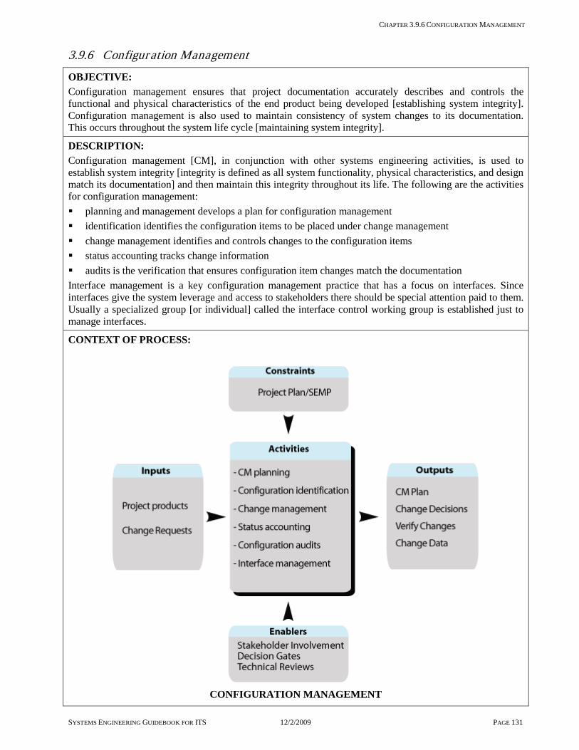
CHAPTER 3.9.6 CONFIGURATION MANAGEMENT
SYSTEMS ENGINEERING GUIDEBOOK FOR ITS 12/2/2009 PAGE 131
3.9.6 Configuration Management
OBJECTIVE: Configuration management ensures that project documentation accurately describes and controls the functional and physical characteristics of the end product being developed [establishing system integrity]. Configuration management is also used to maintain consistency of system changes to its documentation. This occurs throughout the system life cycle [maintaining system integrity].
DESCRIPTION: Configuration management [CM], in conjunction with other systems engineering activities, is used to establish system integrity [integrity is defined as all system functionality, physical characteristics, and design match its documentation] and then maintain this integrity throughout its life. The following are the activities for configuration management: planning and management develops a plan for configuration management identification identifies the configuration items to be placed under change management change management identifies and controls changes to the configuration items status accounting tracks change information audits is the verification that ensures configuration item changes match the documentation Interface management is a key configuration management practice that has a focus on interfaces. Since interfaces give the system leverage and access to stakeholders there should be special attention paid to them. Usually a specialized group [or individual] called the interface control working group is established just to manage interfaces.
CONTEXT OF PROCESS:
CONFIGURATION MANAGEMENT

CHAPTER 3.9.6 CONFIGURATION MANAGEMENT
SYSTEMS ENGINEERING GUIDEBOOK FOR ITS 12/2/2009 PAGE 132
Inputs: Project Products that have been approved to be managed under the CM process throughout the life of the system. Change Request[s] for products under change management control.
Control: SEMP/Project Plan will contain the CM plan[s] for the system’s owner and development team.
Enablers: Stakeholder involvement in the change management board and in changes that affect them. Technical reviews are used to evaluate changes prior to submission to the CM board. Control Gates are used to establish baseline products that allow the project to move forward to the next phase of work.
Outputs: CM Plan contains the process needed to carry out CM for the project. Change Decisions on change requests. Verified changes after the implementation and synchronization to the documentation. Supporting change data that identifies the change and rationale for the change.
Process Activities: Plan configuration management activities There are three application areas that need planning. The agency’s CM plan for the life of the system, the implementation team’s CM plan for development, and the CM Plan for COTS product vendors. The agency’s CM plan should identify the requirements for the development team’s CM plan and vendor’s CM plan and the needed outputs to support the life of the system. Identify configuration items This step identifies items that will be managed under the CM process. These are called “Configuration Items [CI]”. These items exist at all levels of decomposition and occur in each phase of development. For example, baseline requirements and design documents developed during the definition and decomposition of the system are configuration items. When products are identified, e.g. sub-system at the detailed design level, and when the end products of software and hardware are complete functional units, these are product level configuration items. Finally, when the system is deployed, the operational baseline is a configuration item. Manage change This is the process to manage changes to the configuration items. This involves a change management board and documentation that identifies the change, rationale, cost, risk, and priority. Perform status accounting This step collects change data and is used for status and analysis purposes. Perform configuration audits There are two types of audits, [functional and physical]. Functional audits match the product to the functional and performance requirements [acceptance verification]; and physical audits match version numbers and physical identifiers with the documentation. Manage interfaces This step manages the interfaces of the system. This activity controls both external and internal interfaces. Interfaces that are shared with other agencies should have an Interface Control Document [ICD] that contains an memorandum of understand [MOU] that agrees to the specification for the interface.
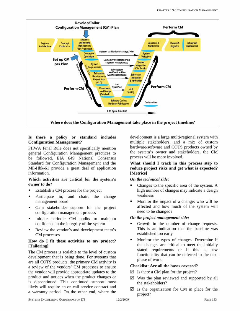
CHAPTER 3.9.6 CONFIGURATION MANAGEMENT
SYSTEMS ENGINEERING GUIDEBOOK FOR ITS 12/2/2009 PAGE 133
Where does the Configuration Management take place in the project timeline?
Is there a policy or standard includes Configuration Management? FHWA Final Rule does not specifically mention general Configuration Management practices to be followed. EIA 649 National Consensus Standard for Configuration Management and the Mil-Hbk-61 provide a great deal of application information. Which activities are critical for the system’s owner to do? Establish a CM process for the project Participate in, and chair, the change
management board Gain stakeholder support for the project
configuration management process Initiate periodic CM audits to maintain
confidence in the integrity of the system Review the vendor’s and development team’s
CM processes How do I fit these activities to my project? [Tailoring] The CM process is scalable to the level of custom development that is being done. For systems that are all COTS products, the primary CM activity is a review of the vendors’ CM processes to ensure the vendor will provide appropriate updates to the product and notices when the product changes or is discontinued. This continued support most likely will require an on-call service contract and a warranty period. On the other end, where the
development is a large multi-regional system with multiple stakeholders, and a mix of custom hardware/software and COTS products owned by the system’s owner and stakeholders, the CM process will be more involved. What should I track in this process step to reduce project risks and get what is expected? [Metrics] On the technical side: Changes to the specific area of the system. A
high number of changes may indicate a design weakness
Monitor the impact of a change: who will be affected and how much of the system will need to be changed?
On the project management side: Growth in the number of change requests.
This is an indication that the baseline was established too early
Monitor the types of changes. Determine if the changes are critical to meet the initially stated requirements or if this is new functionality that can be deferred to the next phase of work
Checklist: Are all the bases covered? Is there a CM plan for the project? Was the plan reviewed and supported by all
the stakeholders? Is the organization for CM in place for the
project?

CHAPTER 3.9.6 CONFIGURATION MANAGEMENT
SYSTEMS ENGINEERING GUIDEBOOK FOR ITS 12/2/2009 PAGE 134
Is there sufficient funding to sustain the CM activities throughout the life of the system?
Does the development team have a CM process and was it reviewed by the system’s owner and stakeholder?
Is the product documentation complete to the extent that the system’s owner can use another qualified development team to upgrade and maintain the system independent of the initial development team? [extremely important]
Does the COTS vendor have a CM process for their products?
Does the vendor provide a notice of design changes?
Does the vendor provide a notice of obsolescence?
Does the vendor provide on-going maintenance support?
Are there any other recommendations that can help?
Configuration management for systems development is a management process for the project products. Configuration
management works together with a good systems engineering process. The systems engineering process provides the orderly establishment of the project products and documentation and Configuration Management is used to maintain consistency between the system changes to its documentation. Use configuration management as an evaluation tool and discriminator for vendors of COTS products and development teams. COTS products for Intelligent Transportation Systems should have a long life through upgrades. A vendor that has a good internal CM process can show how their products are maintained and upgraded. The vendor would not only maintain and upgrade their products on a regular basis, but issue notices of design changes, and notices of obsolescence when products reach their end of life. This type of service would most likely be part of an on-call service contract. Configuration management should not be assumed as part of the project. It must be planned. The cost of Configuration Management on large projects is estimated at around 5% to 10% of the life cycle costs. This data was from an informal poll of systems engineers from the aerospace and defense contractors. This cost covers starting a CM activity from the ground up [10%] or using an
existing in place CM process and extending it to include a new project [5%]. Once a CM process is in place, it should be used for future projects as well. Internal interfaces may need Interface Control Documents [ICD] if the interface is shared with a partner agency's system or sub-system. A closer look at three different environments for configuration management System’s owner has the ultimate responsibility for the system over its life. Various development teams and vendors may be involved in providing or developing products for the system and in providing upgrades, maintenance, and evolution of the system over its life. The system’s owner should have a CM process that covers the life the system. The vendors and development teams working on the system should provide the products and documentation that will be compatible with the system’s owner’s CM plan. Development Team[s] should have their own configuration management processes and tools when developing hardware and software for the system. This CM process addresses the low level procedures needed when software and hardware is developed. The system’s owner should define the expected output from the development team’s process but should not dictate how the development team performs CM. However, inspection of the team’s CM process should show that it conforms to industry standards [see references for a list]. COTS Vendors should have internal CM processes that are documented and followed, and be willing to share their documented processes with the purchaser of their equipment. At a minimum, the vendor should maintain a configuration of the version of the product sold. This configuration should at a minimum identify the following: version of software version of hardware version of the documentation expected support life of the product notices of design changes & obsolescence product updates with revised documentation. These additional services may be available free over a warranty period. For extended periods of support they most likely will be at an additional cost.

CHAPTER 3.9.7 PROJECT PROCESS IMPROVEMENT
SYSTEMS ENGINEERING GUIDEBOOK FOR ITS 12/2/2009 PAGE 135
3.9.7 Project Process Improvement
OBJECTIVE: Process improvement provides a method for the continuous improvement of processes and products over the project life cycle. These process improvements are transferable to future projects [development, operations & maintenance, and retirement/replacement].
DESCRIPTION: At the completion of each phase of a project life cycle, the processes and the quality of products delivered should be reviewed, assessed, and documented. At the completion of the project, the assessment for each phase should be reviewed and summarized as to its impact on the success or shortfalls which occurred during the project. The scope of the assessments should cover: processes [methods and techniques] used during the performance of each phase of the project, the quality of products produced, and the stakeholders [system’s owner, consultants, vendors, and development teams] that were involved. Once documented, the assessment is used to improve the processes in place. Documented lessons learned will capture the “corporate” knowledge gained from the experience of the project. So, the lessons learned can be applied to remaining phases of the existing project and future projects. The assessment has three primary activities: planning, strategy, and performance. This assessment should be an on-going part of each project as part of an overall process improvement effort for the organization, which is described in chapter 7. This can be performed by the system’s owner, other stakeholders, or an independent assessment team.
CONTEXT OF PROCESS:
PROCESS IMPROVEMENT PROCESS

CHAPTER 3.9.7 PROJECT PROCESS IMPROVEMENT
SYSTEMS ENGINEERING GUIDEBOOK FOR ITS 12/2/2009 PAGE 136
Inputs: Delivered phase products delivered products for the phase of work. Process used actual process that was used for the phase of work. Schedules that were used for the phase of work including the original schedule and any updates. Budget/costs developed for the phase of work and any updates.
Control: Project Plan/SEMP contains the process used to carry out each phase of the work, and to determine the process improvements for the project.
Enablers: Stakeholder involvement is essential in process improvement. The stakeholders include the system’s owner, development team, consultants, and all direct stakeholders who were involved in the phases of work. Technical Reviews process is used to carry out the workshops and interview stakeholders on possible process improvements.
Outputs: Lessons Learned Document for each phase of work will identify the strengths and weaknesses of the process and the products of the phase of work. Updates to documented process will be developed as a result of the assessment, and recommended changes to existing documented processes.
Process Activities: Plan Method of Assessment Identify the set of assessment activities needed for the phase of interest. Identify roles and responsibilities, and the timeline for the assessment. Identify the: purpose for the assessment scope of assessment assessment team qualifications team members who should be interviewed Phase products and processes which need to be assessed. Perform Assessment The methods of assessment include interviews, questionnaires, surveys, and workshops. What criteria are established for the documents needing review? For example, an assessment would compare the planned processes to the actual processes, and the planned deliverables with the actual deliverables Consolidate and validate data Document the constraints on the consolidation and validation of the data collected. For example, data that was needed but could not be collected because of security, intellectual, or proprietary information] Collect and consolidate the data from observations of the products and processes in a way that can lead to unbiased conclusions and accurate observations. One technique is to perform two independent reviews and see if the results are the same. Analyze assessment data Reach assessment team consensus on findings, ratings, and validated observations from a minimum of two different sources. Identify strengths and weaknesses of the product and process under assessment. Document lessons learned and updates to process Document the lessons observed and reported from the assessment. Develop a plan to update the process and to migrate to the new and improved practices. Clearly linking the lessons documented to the upgrade of documented processes.
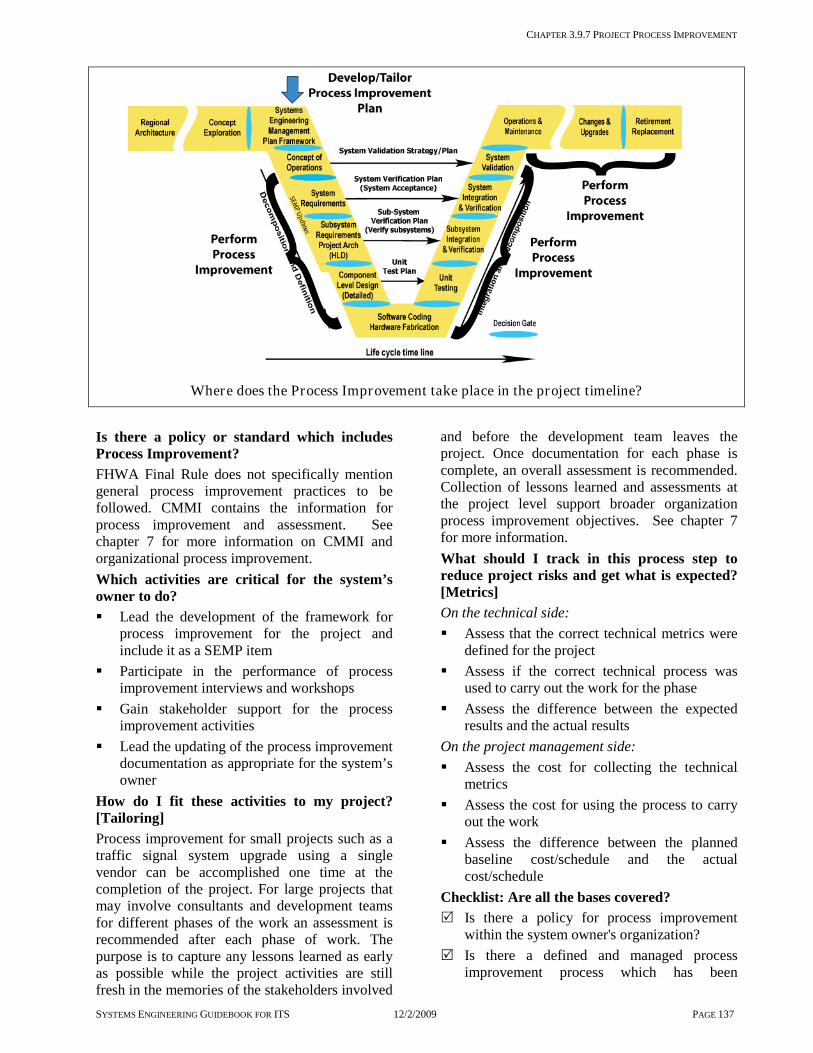
CHAPTER 3.9.7 PROJECT PROCESS IMPROVEMENT
SYSTEMS ENGINEERING GUIDEBOOK FOR ITS 12/2/2009 PAGE 137
Where does the Process Improvement take place in the project timeline?
Is there a policy or standard which includes Process Improvement? FHWA Final Rule does not specifically mention general process improvement practices to be followed. CMMI contains the information for process improvement and assessment. See chapter 7 for more information on CMMI and organizational process improvement. Which activities are critical for the system’s owner to do? Lead the development of the framework for
process improvement for the project and include it as a SEMP item
Participate in the performance of process improvement interviews and workshops
Gain stakeholder support for the process improvement activities
Lead the updating of the process improvement documentation as appropriate for the system’s owner
How do I fit these activities to my project? [Tailoring] Process improvement for small projects such as a traffic signal system upgrade using a single vendor can be accomplished one time at the completion of the project. For large projects that may involve consultants and development teams for different phases of the work an assessment is recommended after each phase of work. The purpose is to capture any lessons learned as early as possible while the project activities are still fresh in the memories of the stakeholders involved
and before the development team leaves the project. Once documentation for each phase is complete, an overall assessment is recommended. Collection of lessons learned and assessments at the project level support broader organization process improvement objectives. See chapter 7 for more information. What should I track in this process step to reduce project risks and get what is expected? [Metrics] On the technical side: Assess that the correct technical metrics were
defined for the project Assess if the correct technical process was
used to carry out the work for the phase Assess the difference between the expected
results and the actual results On the project management side: Assess the cost for collecting the technical
metrics Assess the cost for using the process to carry
out the work Assess the difference between the planned
baseline cost/schedule and the actual cost/schedule
Checklist: Are all the bases covered? Is there a policy for process improvement
within the system owner's organization? Is there a defined and managed process
improvement process which has been

CHAPTER 3.9.7 PROJECT PROCESS IMPROVEMENT
SYSTEMS ENGINEERING GUIDEBOOK FOR ITS 12/2/2009 PAGE 138
institutionalized within the system owner's organization?
Have resources been allocated to the process improvement activity?
Is there training for process improvement within the system owner's organization?
Was a process for a project assessment developed as part of the project plan/SEMP?
Were the key stakeholders identified for the project assessment?
Were the key stakeholders for the phase interviewed as to the strengths and weaknesses in the performance of the phase of work?
Are the assessments accomplished in an objective manner?
Were the assessment results documented and used to update existing processes?
Were meeting minutes and notes kept for the assessment?
If a key stakeholder leaves the project, were they interviewed on the strengths and weaknesses of the phase of work?
Is there a plan for on-going process improvement throughout the operations & maintenance phase of the project?
Are there any other recommendations that can help?
Establish a documented system /software project management process. Before process improvement can be made, an
initial process must be established as a baseline. Tools will help establish and assess the system’s owner and development team’s capabilities. The Software Institute at Carnegie Mellon University has established the Integrated Capabilities Maturity Model [CMMI]. This model identifies the capabilities needed and the assessment tools used to rate an organization on its capability to perform systems/software development and project management. See chapter 7 for more information about CMMI and organizational process improvement.

CHAPTER 3.9.8 DECISION GATES
SYSTEMS ENGINEERING GUIDEBOOK FOR ITS 12/2/2009 PAGE 139
3.9.8 Decision Gates
OBJECTIVE: Decision Gates define major control points that are used to move from one phase of the project to the next. A control gate is used to determine if the products for the current phase of work are completed based on the criteria set out at the beginning of the project and that the project is ready to move forward to the next phase. Controls are used to get formal sign off of that phase of work by the system’s owner and management.
DESCRIPTION: Decision gates are used as a formal way to conclude and accept the products for a particular phase of the project. Intelligent Transportation Systems development, as laid out in this guidebook, has 6 major phases to the system life cycle. Each phase has a major control gate and there are several additional control gates that occur within phases 1, 2, and 3 of the system life cycle. These additional control gates are needed during the definition, development, integration, verification, and deployment of the system. The additional decision gates are used to evaluate the body of development work accomplished for the current phase of the development and determines if the project is ready [staff, funding, documentation, and products] to start the next phase of development. It is important that the following activities be performed in advance of a decision gate: plan how a decision gate is to be conducted identify the participants including their roles and responsibilities define the entrance criteria [what needs to happen before a control gate review takes place] define the exit criteria [what conditions must be met before the next phase or step begins] Decision gates are points at which the system’s owner has formally approved the completion of work for the current phase, and has approved the team to move forward to the next phase. This approval is in the form of a written sign-off of the phase of work, and a notice to proceed to the next phase.
CONTEXT OF PROCESS:

CHAPTER 3.9.8 DECISION GATES
SYSTEMS ENGINEERING GUIDEBOOK FOR ITS 12/2/2009 PAGE 140
DECISION GATE PROCESS
Inputs: Planned Phase/Step Products and Schedule that were to be produced during this phase/step. Current Phase/Step Products that are produced or developed during the current phase/step. Next Phase/Step Products and Schedule defines the plan and list of planned products that are to be developed for the next phase/step of work. [If this is a termination point for the effort of a team then this may be an internal plan for the next contract or an effort for a different organization] Control: SEMP/Project Plan defines the control gate process and criteria for approvals. Enablers: Technical reviews identify the process for conducting the technical review. Stakeholder involvement is essential to come to an agreement on the completion of work for this phase and on the plans to move the project forward to the next phase/step. Outputs: Decision Gate Plan is placed in the SEMP and will determine the process and criteria for performing a control gate. Completion of all phase/step activities and products all phase/step activities and products should have been completed for this phase/step of work. Approved waivers and deviations include any anomaly that have occurred, but does not prevent the team from moving to the next phase of work. Needs to be documented and approved by the system’s owner before proceeding to the next phase. Decision to move forward or to revisit a current phase/step activity is made at this time. It may be that the phase work is not ready to move forward to the next phase and need to be reworked. These decisions are made and the plans are updated to reflect these decisions. Also, the team needs to show that they have the needed resources to move forward. Process Activities: Plan control gates reviews Plan the conduct of a decision gates and who should attend, roles and responsibilities, what is the entrance & exit criteria. Define entrance criteria Before performing a control gate activity, the phase/step products and schedule should be reviewed and the presentations developed in accordance with the plan. The purpose is to demonstrate that the phase of work has been completed. This may include, for example, the approved requirements document and verification plans, acceptance test results, and the completion of all action items. If there is unfinished work and its completion needs to be moved to the next phase/step, this needs to be identified with supporting rationale. Deviations or waivers should be issued on defective or incomplete work. Deviations allow the work to be used as-is permanently; and waivers allow the work to be used on a temporary basis until the defective/incomplete work is corrected. Define exit criteria If this is a continuation of effort, then a plan for the next phase/step of work is presented to ensure that the schedule, list of deliverables, and resources are updated and in place in order to move forward to the next phase/step. If there is any dependency on work done in the current phase, this work is reviewed to ensure it will support the next phase/step. If, at this decision gate, the current effort is at an end or there is a change in the scope of work for the next phase, this will provide a clear point of departure. For example, if the regional architecture work is completed and now projects are being implemented [control gate at phase 1], there may be a different system’s owner as well as a different development team. After the control gate at phase 3 there may be a different development team brought in for hardware/software development. Perform formal review Performing the control gate review should be done in accordance with the process developed for performing a technical review [see Technical Reviews].

CHAPTER 3.9.8 DECISION GATES
SYSTEMS ENGINEERING GUIDEBOOK FOR ITS 12/2/2009 PAGE 141
Where do Decision Gates take place in the project timeline?
Is there a policy or standard that talks about Decision Gates? FHWA Final Rule does not specifically mention general control gate practices. IEEE 1028-1988 Standards for Reviews and Audits provides information that is useful to control gates. Which activities are critical for the system’s owner to do? Lead the planning of the control gate activities
including the entrance and exit criteria Lead the control gate reviews and gain
stakeholder support for decisions made Identify and gain stakeholder support and
participation in the control gate activities Lead the follow-up on any action items as a
result of the control gate, including updating any plans, schedules, deliverables, waivers and deviations to the work
How do I fit these activities to my project? [Tailoring] Project size and number of stakeholders are the driving factors for this activity. On small projects where the system’s owner may be performing the control gate activities alone, the control gate can be very informal and meeting minutes may be the only documentation needed to move the project forward. In multi-regional systems where there are a large number of stakeholders, the control gate activities will not be as simple, especially when a consensus is sought for all decisions. A more formal and planned control gate will be
needed where all of the stakeholders are involved in the planning activities and setting the criteria. What should I track in this process step to reduce project risks and get what is expected? [Metrics] On the technical side: Track the technical objectives for the
phase/step and compare them with the planned technical objectives. Do the technical objectives meet the planned objectives? Were the correct technical objectives achieved?
Incomplete technical objectives or different technical objectives leads to increased technical risk and increased cost
At the decision gate, is all documentation complete and/or does the documentation match the products required for the phase/step? Deficiencies in documentation will lead to reengineering portions of the product later on
On the project management side: Track all products of the phase of work
against the plan Track deficiencies and their impact on the
next phase of work. The next phase can be started even with deficiencies in the current phase of work. If there are deficiencies, the appropriate deviations or waivers must be issued
CHAPTER 3.9.8 DECISION GATES
SYSTEMS ENGINEERING GUIDEBOOK FOR ITS 12/2/2009 PAGE 142
Checklist: Are all the bases covered? Is the plan for the control gate review
included in the SEMP? Does it include entrance criterion? Does it include an exit criterion? Does it identify who should attend? Does it identify how the control gate will be
conducted? [formally or informally] Have the entrance criteria been met prior to
the control gate review? Have all phase/step products been reviewed
and approved? Have the exit criteria been met for the next
phase/step. Have all waivers and deviations been issued if
any? Have the appropriate stakeholders been
invited to the Control Gate review? Has the Control Gate review been conducted
IAW the technical review process? Are there any other recommendations that can help?
Have the appropriate stakeholders been involved in the decision gate review. Frequent changes in
stakeholders can be an obstacle to moving a project forward. If new stakeholders become involved mid-stream and they have not been completely updated on the project, they can cause “old” ground to be covered again. When it comes to a control gate it is not the time to train new stakeholders on a project. A closer look a the life cycle decision gates for ITS systems Project Approval Decision Gate: [Phase 1] Out of the regional architecture a number of projects were proposed and a feasibility analysis was performed to provide a business case. This control gate approves projects to move forward to development and implementation.
Planning Decision gate: [Phase 1] Planning decision gate reviews the Systems Engineering Management Plan [SEMP] to see if all the plans are complete enough to start the project. Concept of Operations Decision Gate [Phase 2] Upon completion of the Concept of Operations, the control gate is used to see if the SEMP and Concept of Operations are complete and the stakeholders are in agreement on how the system is to work. This control gate initiates the system definition phase of work. Requirements Decision Gate [Phase 2] This gate approves the system level requirements and the verification plans that will be used by the development team to implement the system. High level Design Decision Gate [Phase 3] Here the high level design for the system is approved and is ready for the development team to start the component level detailed design. Sometimes this is called a Preliminary Design Review [PDR]. Component Level Detailed Design Decision Gate [Phase 3] This is the completion of the detailed design and the project is now ready for hardware/software development and purchase of COTS products. This is sometimes called the Critical Design Review [CDR] Test Readiness Review Decision Gates [phase 3] This is a series of control gates that review the readiness of products from the development team to be verified, starting at the lowest level products and working up to sub-systems, and finally to system acceptance. Operational Decision Gate [Phase 4] This control gate approves the system to be commissioned into operation and maintenance. System Retirement/Replacement Decision Gate [Phase 5] This control gate approves the system to be retired or replaced in part or in whole.

CHAPTER 3.9.9 DECISION SUPPORT/TRADE STUDIES
SYSTEMS ENGINEERING GUIDEBOOK FOR ITS 12/2/2009 PAGE 143
3.9.9 Decision Suppor t/Trade Studies
OBJECTIVE: Trade studies compare the relative merits of alternative approaches, and so ensure that the most cost-effective system is developed. They maintain traceability of design decisions back to fundamental requirements. Trade studies do this by comparing alternatives at various levels for the system being developed. They may be applied to concept, design, implementation, verification, support, and other areas. They provide a documented, analytical rationale for choices made in system development.
DESCRIPTION: Trade studies can be used in various phases and at different depths throughout the project to select from alternatives or to understand the impact of a decision. The inputs vary depending on what is being analyzed. For example, in concept exploration, the alternatives will be concepts. While, in the design phase, they will be design alternatives. The stakeholders are essential here to define and rate the criteria and to validate the results. The analysis may be done qualitatively, or by a model or simulation.
CONTEXT OF PROCESS:
TRADE STUDIES PROCESS

CHAPTER 3.9.9 DECISION SUPPORT/TRADE STUDIES
SYSTEMS ENGINEERING GUIDEBOOK FOR ITS 12/2/2009 PAGE 144
Inputs: These inputs will be used only as available. Project Goals and Objectives drive the selection of alternatives for concepts. User needs and Concept of Operations drive the selection of alternatives for requirements. Requirements and High Level Design drive the selection of alternatives for design elements. Control: SEMP and Project Plan constrain what may be developed, and define budget and schedule. Enablers: Stakeholder involvement provides the key metrics and may suggest alternatives. Risk assessment evaluates each alternative relative to risk, balanced against effectiveness. Technical reviews present the results and gather inputs and feedback. Outputs: Selection of the best of the alternatives, whether for concept, requirements, design, or implementation, provides a choice based on solid analysis. Rationale is the documentation of the alternatives compared, the criteria for selection, the analysis methodology, and the conclusions. Process Activities: Define the decisions to be made First, define the question the trade study is to answer. This may be the selection of the most cost-effective concept or design. It may be to narrow down choices for more detailed evaluation. It may be to demonstrate that the choice made is the best one. Define criteria Experienced specialists will draw from the available inputs to identify the key evaluation criteria for the decision under consideration. These are measures of effectiveness, metrics that compare how well alternatives meet the needs and requirements. Examples are capacity [vehicles per hour], response time, throughput, and expandability. Define weightings Generally, there are multiple criteria, and so these same experts will assign each of them a relative weighting for relative importance. Identify alternatives Trade study starts with alternative concepts or designs that are to be evaluated. Be sure that all reasonable alternatives are on the table. Evaluate performance Generally, the emphasis is on performance criteria such as speed or effectiveness. For each alternative, the criteria may be evaluated quantitatively or qualitatively, and by such methods as simulation, performance data gathered from similar systems, surveys, and engineering judgment. These disparate evaluations are merged using the weighting factors to give a measure of overall effectiveness for each choice. Assess cost, risk, and schedule Estimate the cost of each alternative: the development cost and the life cycle cost, which includes operation and maintenance. Use the techniques of risk assessment [see Chapter 3.9.4] to compare the alternatives relative to technical or project risk. Determine the impact of each alternative on the schedule. Eliminate those that introduce too much risk of missing deadlines. Analyze alternatives Sensitivity analysis may also be used, especially with simulation, to see the effect of changes in sub-system parameters on overall system performance. The sensitivity analysis and the evaluations may suggest other, better alternatives. Select and document the preferred candidate Plotting each alternative's [concept or design] overall effectiveness, based on the combined weighted metrics, against cost, or the other factors, is useful for evaluating the relative merits of each. It supports stakeholders in making a good decision. Document the decision and the rationale behind it, to provide traceability back to the higher-level requirements. This document is also a repository of alternatives, in case a change is needed down the road.

CHAPTER 3.9.9 DECISION SUPPORT/TRADE STUDIES
SYSTEMS ENGINEERING GUIDEBOOK FOR ITS 12/2/2009 PAGE 145
Where do trade studies take place in the project timeline?
Is there a policy or standard that talks about Trade Studies? FHWA Final Rule requires the analysis of system configurations to meet requirements. Which activities are critical for the system’s owner to do? Ensure that the proper stakeholders are
involved Suggest or elaborate on decision criteria Review the process and results of the trade
studies How do I fit these activities to my project? [Tailoring] The level of each activity should be appropriately scaled to the size of the project and the importance of the issue being traded off. For example, a small project will use qualitative measures and compare a small number of alternatives, and sensitivity analysis. For example, an upgrade to a signal system will trade off features based on stakeholder priorities. A large project may use simulation to analyze key issues and perform sensitivity analysis. What should I track in this process step to reduce project risks, and get what is expected? [Metrics] On the technical side: These metrics check whether the set of alternatives is possibly driving a risky solution Number of high-risk alternatives selected
Number of high-cost alternatives selected Number of selected alternatives that introduce
schedule risk On the Project management side: Percentage of alternatives examined Percentage of planned sensitivity analyses
completed Checklist: Are all the bases covered? Has a broad and reasonable selection of alternatives been examined? Does the rationale for the trade study conclusions flow out of the needs and requirements? Is the sensitivity of system effectiveness to changes in key parameters well understood? Is the selection rationale documented? Are there any other recommendations that can help? Trade studies should make maximum use of any previous work, but if nothing applicable is available, it will need to include more technical analysis. Often the two methods are combined by using analysis to predict system performance based on that of other systems. For example, well-documented improvements in traffic flow experienced when another agency implemented ramp metering could be combined with local data to predict the potential impact of a local ramp metering system.

CHAPTER 3.9.9 DECISION SUPPORT/TRADE STUDIES
SYSTEMS ENGINEERING GUIDEBOOK FOR ITS 12/2/2009 PAGE 146
Simulation and modeling are tools which provide an objective, quantitative comparison of the merits of the alternatives. They may, for example, predict the effectiveness of each alternative in an operational scenario. These can range from a simple spreadsheet to a full traffic simulation. A closer look at combining metrics There are usually multiple metrics for evaluating the system based on the various needs that the system is to meet. Generally, they are a mix of positive metrics [more is better such as highway capacity] and negative metrics [less is better such as response time]. They also include both quantitative [e.g., predicted vehicle hours of delay] and qualitative values e.g., [relative rating from 1 to 10]. The units can vary as follows: vehicles per lane per hour seconds [of workstation response time] minutes [of incident response time] number [of predicted fatalities] % [of time available] It requires care to combine these into some measure of overall system technical measure, without giving undue weight to one or the other. Chapter 3.9.5 gives a method for doing this. Making qualitative measures quantitative Often time and available information do not allow a direct quantitative assessment. For example, the design of a regional Advanced Transportation Information System [ATIS] focuses on the key information needs of a large number of agencies in the region. There was very little time to do this prioritization, but there were dozens of documents that the agencies had produced discussing their needs. The approach used was to draw out, from documents, any needs cited. Some agencies listed their “top ten” information needs in rank order. These were assigned 1 to 10 points, depending on their place in the list, 10 being best. If a need was cited without ranking it relative to other needs, it was given a medium rating of 5 points. The total points for any need were then given a metric indicating how many agencies needed the particular information, and how strongly they felt about it. If workshops are held to collect stakeholders’ preferences, here is a simple way to get their
inputs on alternatives. First, discuss the alternatives and their pros and cons. Then, list them on a flipchart and give each participant a few colored adhesive dots. Be sure each participant gets the same number of dots, about 10 – 20% of the number of alternatives. Allow each participant to place their dots next to the choices that they favor, even placing multiple dots against a choice that they particularly like. The number of dots is a metric for stakeholder preference. This type of metric could be used to compare alternatives directly or to determine relative weights for multiple metrics. Sensitivity analysis Simulation, or other analytical tools, can be used to vary design parameters over their potential values and predict the effect on performance. The “knee of the curve” shows where more stringent design requirements give little system improvement.
0
5
10
15
20
25
30
35
40
45
0 5 10 15 20 25 30 35 40
In the example chart, the knee of the curve occurs around 15 to 20 for the design parameter [horizontal axis]. There is very little performance improvement [vertical axis] from a more stringent design. Sensitivity analysis can also be done in multiple dimensions to determine, for example, whether money should be spent on improving communications or detectors. Estimating costs for alternatives There is an art to predicting the cost of a new system. A life cycle cost analyst can do it by extrapolating from existing systems. Qualitative assessments are often sufficient. Examples are high/medium/low, in cost or difficulty to implement. Plotting effectiveness versus cost would support the decision.

CHAPTER 3.9.10 TECHNICAL REVIEWS
SYSTEMS ENGINEERING GUIDEBOOK FOR ITS 12/2/2009 PAGE 147
3.9.10 Technical Reviews
OBJECTIVE: Technical reviews provide a structured and organized approach to reviewing project products to determine if they are fit for their intended use. This chapter also describes a process to plan and conduct a meeting that can be used for the different types of technical reviews. Technical reviews are used to identify design defects, suggest alternative approaches, communicate status, monitor risk, and coordinate activities within multi-disciplinary teams.
DESCRIPTION: Technical reviews are critical to the success of Intelligent Transportation System projects. Technical reviews provide status and feedback on the products under review and the on on-going activities of a project. A technical review is the primary method for communicating progress, coordinating tasks, monitoring risk, and transferring products and knowledge between the team members of a project. The Institute of Electrical and Electronics Engineers [IEEE] 1028-1998 identifies the following five types of reviews:
1. management reviews [for example, control gates] 2. technical reviews 3. inspections [primarily for identifying errors or deviations from standards and specifications] 4. walk-through [for example, requirement or design walk-through] 5. audits [for example, physical and functional audits used as part of the configuration management
process] The process for conducting review meetings should be established in the Project Plan/SEMP and carried out the same way for each review. The differences in reviews would be in the content and level of formality. This formality would be tailored for the type of review and its purpose. This chapter describes a basic meeting procedure including pre-meeting activities, conduct, and post meeting activities.
CONTEXT OF PROCESS:
TECHNICAL REVIEW PROCESS

CHAPTER 3.9.10 TECHNICAL REVIEWS
SYSTEMS ENGINEERING GUIDEBOOK FOR ITS 12/2/2009 PAGE 148
Inputs: Purpose for the meeting must be clearly established with expected outcomes. Required Review Inputs should be provided. These are products for the phase under technical review. Unresolved action items from the previous reviews are carried over for continuing discussion and/or decisions. Control: Project Plan/SEMP contains the process used to perform technical reviews. Enablers: Stakeholder involvement is needed to participate and to fill the various roles for the technical reviews. Outputs: Project Review Plan will identify how technical reviews will be carried out for the project. This will be part of the Project Plan/SEMP. Review of decisions includes the documented acceptance; re-work with comments, and deviations and waivers to the phase products by the participants of the technical review. Action items are assigned with completion dates. Critical items are tracked between meetings if necessary. Assignments are documented and sent out as part of the feedback to the participants. This feedback should have a definition of the action item and a planned date for completion. Feedback to participants the results of the meeting and provide a record of the meeting for their review and comments. This ensures that decisions, actions, and assignments were accurately documented. Process Activities: Plan reviews A plan is developed for the technical reviews of a project. This plan includes the schedule for reviews, who [functionally] will be in attendance, the level of formality for each review, the entry criteria [drafts, final products], the process for the review [structured presentation or informal round-table], and the exit criteria [100% consensus agreement, majority agreement, project manager only]. Perform pre-meeting [review] activities Define the purpose, objectives, and the intended outcomes of the meeting. Prepare an agenda, identifying participants and their roles and distributing the agenda and background material. Reserve and inspect the meeting facilities and location to see if all needed equipment is in working order and that the facility meets the needs for the meeting. Example items to look for are space [size and shape], break rooms, rest rooms, lunch facilities, break-out rooms, climate control, lighting, noise levels, appropriate furniture and configuration, equipment, and electrical. Make arrangements, if necessary, for breakfast, lunch, dinner, and/or break refreshments. Perform meeting/review Technical meetings should start and end on time. The purpose of the meeting should be clearly stated, an updated agenda provided to the attendees, and a roster that documents the attendees present with up to date contact information [email, phone number, organization]. Their role [e.g. presenter, chairman, or observer] in the meeting should be placed with the meeting minutes. The ground rules for the meeting should be reviewed prior to discussion, starting with unresolved action items from the previous review. Conclude one agenda item at a time. Manage discussions so that there is focus on the topic. Follow the pre-arranged ground rules. Keep track of the time. Document all decisions, actions, and assignments. At the close of the meeting, summarize all decisions, actions, and assignments, review agenda items, and assignments for the next meeting. Confirm date, time and place of the next meeting. Finally, end on time. Perform post meeting/review activities The meeting should be followed up with a complete set of minutes that include all decisions, actions, and assignments. The minute taker, if needed, should follow up with the attendees to make sure the minutes are as complete as possible. These minutes and any supporting material should distributed back to the attendees promptly for review and comment. Assignments should be completed, and periodic progress checks on critical action items from the meeting. Honor commitments for the next meeting. Carry over unresolved actions with status and recommended resolutions.

CHAPTER 3.9.10 TECHNICAL REVIEWS
SYSTEMS ENGINEERING GUIDEBOOK FOR ITS 12/2/2009 PAGE 149
Where do Technical Reviews take place in the project timeline?
Is there a policy or standard that talks about Technical Reviews? FHWA Final Rule does not specifically mention general reviews and meeting practices. IEEE 1028-1988 Standards for Reviews and Audits provides information useful to decision gates. Which activities are critical for the system’s owner to do? Lead the definition and documentation of the
process in conducting a technical review. Gain stakeholder support in the participation
of technical reviews Lead the participation of technical reviews Review decisions, actions, and assignments
from the technical review Follow-up on critical assignments How do I fit these activities to my project? [Tailoring] In this activity, the number of reviews and level of formality is tailored to the size and type of the project. For example, on a small traffic signal control system that is a COTS product, the number of reviews can be minimal [bi-weekly or monthly]. The meetings may be informal with the project manager and/or traffic engineer in a review of progress. The feedback may be just a summary of the meeting minutes.
What should I track in this process step to reduce project risks and get what is expected? [Metrics] Technical and project management: Technical reviews are used to identify design defects, suggest alternative approaches, communicate status, monitor risk, and coordinate activities within multi-disciplinary teams. This would be the time and place to monitor, review, and take action on both technical and project management metrics that were set up for the phase currently in progress. Checklist: Are all the bases covered? Was a review plan developed for the project?
Did the plan contain: - The number or frequency of the reviews? - The process for carrying out each review? - Roles identified for each review? - Level of formality identified for each
review? Was a technical review agenda developed and
distributed well ahead of the scheduled meeting date?
Was all the supporting and background material generated and distributed to the attendees well ahead of the scheduled meeting date [per the plan]?
Were the attendees and their roles identified or defined [per the plan]?
Were the time and location identified?

CHAPTER 3.9.10 TECHNICAL REVIEWS
SYSTEMS ENGINEERING GUIDEBOOK FOR ITS 12/2/2009 PAGE 150
Were the purpose and outcomes identified? Were all unresolved assignments, identified in
the previous meeting, brought forward to the upcoming meeting?
Has the location of the technical review been checked out for size, climate, configuration, equipment, furniture, noise, and lighting?
Are all the presenters well prepared for the meeting?
Were the ground rules for the meeting discussed before the start of discussion?
Did the meeting start on time? Were introductions made by all attendees? Was an attendance roster created for the
meeting with up to date contact information for each attendee?
Was the purpose of the meeting clearly stated and what are the expected outcomes?
Was an updated agenda provided for each attendee with the priorities assigned for each agenda item?
Was each agenda item concluded before discussing the next or other items?
Were all decisions, assignments, and actions documented as part of the minutes and summarized at the end of the meeting?
Did the meeting end on time? Were the minutes distributed to the attendees? Were all critical assignments followed up
between meetings? Are there any other recommendations that can help?
Have ground rules for technical reviews. The following is a recommended set of ground rules that participants observe
during the meeting: We tell it like it is, but respect, honor, and
trust one another We work toward consensus, recognizing that
disagreements in the meeting are okay. Once we agree, we all support the decision
We have one conversation at a time; and our silence is consent
We focus on issues, not on personalities; and we actively listen and question to understand
We do not attack the messenger We start on time, observe time limits, and
structure the agenda to end on time A closer look at the types of technical reviews used throughout the project timeline Planning review verifies that plans appropriate for the project are identified. Tailoring for each plan is reviewed and updated as needed. Concept of Operations review ensures that the operation of the system being defined is appropriate, and addresses the needs of the stakeholders. This is a critical review, as the concept of operations will identify the operational needs, needed agreements, candidate external interfaces, and maintenance responsibilities. Requirements review is used to ensure the system and sub-system requirements and verification plans are appropriate for the system being defined. This review verifies that the requirements are complete and that each meets all the criteria for a good requirement and traces to user needs. High level Design review ensures that the project level architecture is well formed, balanced, and appropriate for the problem space, and that the functionality and performance of the defined system meet the intended need. This review verifies that the project architecture is consistent with the regional architecture. If necessary, document the differences. This is a major technical review and is sometimes called a PDR [Preliminary Design Review]. Component level detailed design review is used to ensure that the detailed design is ready for implementation. This is a major review since when completed, the detailed design is ready for implementation. This is sometimes called the CDR [Critical Design Review]. Test Readiness review is used to see if the components, sub-systems, and system are ready for verification. For each level of verification, there should be a review prior to the formal verification of the product. Operational Review is used to ensure that the system is ready for deployment. This review verifies that all training and support for the system is in place and that the operations & maintenance personnel are ready.

CHAPTER 3.9.11 TRACEABILITY
SYSTEMS ENGINEERING GUIDEBOOK FOR ITS 12/2/2009 PAGE 151
3.9.11 Traceability
OBJECTIVE: Traceability ensures that user needs and concepts are addressed by a set of requirements and that the requirements are fulfilled by the high level and detailed design. Traceability also ensures that system and sub-system requirements are fully verified. Traceability supports impact analysis and configuration management for long term maintenance, changes & upgrades, and replacement to the system.
DESCRIPTION: Traceability follows the life of a requirement throughout the life of the system. Each requirement is traced to its parent requirement and to its allocated sub-system requirement [bi-directional traceability]. User needs and requirements are also traced to their associated verification & validation plans. The following are three aspects of traceability:
1) Pre-Requirements Specification traceability [Pre-RS traceability] in which user needs are traced to a set of system requirements
2) Post-Requirements Specification traceability [Post-RS traceability] in which traceability ensures compliance after the system requirements baseline has been established
3) Post delivery traceability [Post-Delivery traceability] in which traceability is maintained after delivery of the system; supporting changes & upgrades, and replacement activities.
CONTEXT OF PROCESS:
TRACEABILITY PROCESS

CHAPTER 3 Traceability
Systems Engineering Guidebook for ITS 12/2/2009 PAGE 152
Inputs: User needs/requirements the initial needs and wants of the stakeholders. Concept of Operations & Validation artifacts detailed concepts needed by the system and associated validation that will meet the stakeholder needs. System and sub-system requirements, verification plans, and procedures requirements, associated verification cases for each requirement to be verified, and the procedures for verification Detailed Design & Implementation artifacts "build-to" products used for implementation and fabrication of the system elements and associated Software and Hardware implementation artifacts [source code, fabrication drawings] Support artifacts related documentation needed to maintain and operate the system [users & maintenance manuals, external requirements e.g. traceability to the regional architecture, safety requirements] Control: Project Plan/SEMP defines the extent of traceability needed for the project. For example, safety critical systems will need more comprehensive traceability to ensure compliance with safety requirements. Enablers: Requirements Management Tools enable the management of traceability through compliance and changes Configuration Management supports management decisions using traceability Outputs: Traceability Matrix documents the traceability of the requirements and related artifacts Compliance reports analyze all links to ensure that there is no orphan or unsupported requirements. Disposition of orphan and/or unsupported requirements all orphan and unsupported requirements are identified and the disposition determined for each [e.g., remove or add new requirements] Process Activities: Pre-RS Traceability Traces user needs/requirements and concepts to system requirements. When user needs/requirements are prioritized, this tracing enables the system requirements to inherit the priority of the user needs, supporting system requirements prioritization schemes. When user needs/requirements change, traceability supports technical, budget, and schedule impact assessments. Traceability is bi-directional, in that not only all the user needs and requirements trace to system requirements, but that all system requirements can be traced back to an associated user need/requirement that unsupported requirements are not inadvertently inserted. This bi-directional traceability is applied to all requirements at every level. Define extent of Traceability Determine the extent of traceability needed based or the criticality or regulatory issues of the system. Post-RS Traceability Post Requirements Specification traceability activities begin when a requirement baseline established. This includes tracing system requirements through sub-system requirements, design, implementation, and verification. Traceability enables the system owner to determine if all requirements are being implemented and verified. Traceability is used to determine the development team’s compliance to the requirements and that all contracted functionality is verified. Changes occur during development, traceability supports the technical, budget, and schedule impact assessments. Traceability supports the impact of changes during the verification by determining how much regression testing is needed to satisfy the changes. Bi-directional traceability shows that system requirements are addressed by sub-systems, and that all sub-systems have supporting system requirements. Traceability can be used to trace to other supporting project artifacts as well, such as user & maintenance manuals, training, deployment, logistics, and production products. Post-Delivery Traceability Post-Delivery traceability is used to maintain the system. This activity continues though-out the life of the system. Traceability supports technical, budget, and schedule impact assessments when changes and upgrades are needed, and extends into replacement and retirement of the system. Traceability is used to demonstrate integrity of the systems by verifying that the functional and physical characteristics are traceable to its associated requirements and design documentation.
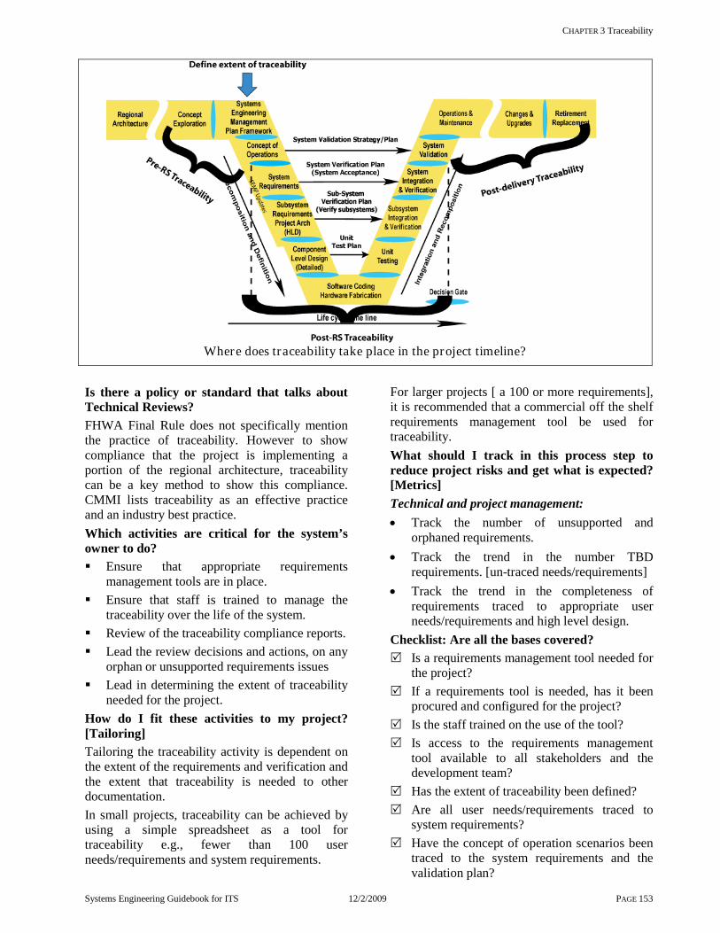
CHAPTER 3 Traceability
Systems Engineering Guidebook for ITS 12/2/2009 PAGE 153
Where does traceability take place in the project timeline?
Is there a policy or standard that talks about Technical Reviews? FHWA Final Rule does not specifically mention the practice of traceability. However to show compliance that the project is implementing a portion of the regional architecture, traceability can be a key method to show this compliance. CMMI lists traceability as an effective practice and an industry best practice. Which activities are critical for the system’s owner to do? Ensure that appropriate requirements
management tools are in place. Ensure that staff is trained to manage the
traceability over the life of the system. Review of the traceability compliance reports. Lead the review decisions and actions, on any
orphan or unsupported requirements issues Lead in determining the extent of traceability
needed for the project. How do I fit these activities to my project? [Tailoring] Tailoring the traceability activity is dependent on the extent of the requirements and verification and the extent that traceability is needed to other documentation. In small projects, traceability can be achieved by using a simple spreadsheet as a tool for traceability e.g., fewer than 100 user needs/requirements and system requirements.
For larger projects [ a 100 or more requirements], it is recommended that a commercial off the shelf requirements management tool be used for traceability. What should I track in this process step to reduce project risks and get what is expected? [Metrics] Technical and project management: • Track the number of unsupported and
orphaned requirements. • Track the trend in the number TBD
requirements. [un-traced needs/requirements] • Track the trend in the completeness of
requirements traced to appropriate user needs/requirements and high level design.
Checklist: Are all the bases covered? Is a requirements management tool needed for
the project? If a requirements tool is needed, has it been
procured and configured for the project? Is the staff trained on the use of the tool? Is access to the requirements management
tool available to all stakeholders and the development team?
Has the extent of traceability been defined? Are all user needs/requirements traced to
system requirements? Have the concept of operation scenarios been
traced to the system requirements and the validation plan?

CHAPTER 3 ITS Life cycle Processes
SYSTEMS ENGINEERING GUIDEBOOK FOR ITS 12/2/2009 PAGE 154
Have the system requirements been traced to the system verification plan?
Have the system requirements been traced to the high level design?
Has the high level design been traced to the sub-system verification plans?
Has the high level design been traced to the detailed design?
Has the detailed design been traced to the unit verification plan/procedures?
Has the detailed design been traced to implementation artifacts [SW source code, HW documentation etc]?
Have the verification procedures been traced to the verification plans at all levels?
Has all needed supporting project documentation been traced?
Has traceability been maintained during the operations & maintenance, changes & upgrades, and retirement & replacement?
Are there any other recommendations that can help? For projects that have 100 system requirements or more, procure and use a requirements management tool to capture, trace, and manage the project requirements. The tool should be installed and configured in
the early stages of the project Staff should be trained in the use of the tool The tool should have the capability such that
the staff in all districts have access to the tool The tool should be able to trace within and
between classes of the schema. The tool should support document generation,
or interface with a document generation tool. The tool should provide a change
management capability where stakeholders can recommend changes to requirements and traceability.
For small project [less than 100 requirements], a spreadsheet may be used to capture and trace requirements. A schema must be defined on what
are the naming conventions and how the links will be identified. This is a low cost approach but in the long term it may be more labor intensive. The choice of the tools should be determined on the long term growth of the system. A closer look at using requirements management tools for traceability. There are a number of requirements management tools on the market.[see appendix 7.2.5 for a list of requirements engineering tools] A basic capability of all these tools is traceability. Requirements management tools need a database to support the tool. Most of them today use a commercial database such as Oracle, but a few requirements management tools still uses their own proprietary databases. This can be an issue for portability and agency standards. These tools require an up front investment in procuring a license and in staff training. The range in cost from $10K-$15K dollars [license & training] plus staff time in the set up for each project. In most tools a database scheme needs to be developed for each project [A couple tools provide a generic project set up that can be used or modified.]. Part of the project planning and definition is the identification of the requirements attributes. The requirements management tool supports this by allowing the systems engineer to define as part of the tool, the classes that the project wants to capture for example, Systems Requirement, Systems Verification, and the bi-directional links between these classes allowing traceability. Once a requirements management tool is set up it will require staff to maintain and keep it up to date. The tool will also require an on-going maintenance contract to receive updates and support. In the long term, requirements management tools can be a good investment in saving time and budget when assessing changes to a system, required testing, and verifying compliance of the system to requirements.

CHAPTER 4 Systems Engineering Environment
SYSTEMS ENGINEERING GUIDEBOOK FOR ITS 12/2/2009 PAGE 155
4 Systems Engineer ing Environment OBJECTIVE:
This chapter discusses a number of issues that affect the application of systems engineering for intelligent transportation projects. This chapter focuses primarily on institutional and project issues, such as why systems engineering is needed, how much systems engineering is needed for an ITS project, the relationship of systems engineering to existing agency systems engineering practices, and procurement issues. Finally, it focuses on the relationship of systems engineering to ITS standards, transportation planning, the ITS architecture, and Federal Final Rule. The following sub-sections is an overview of the Systems engineering environment described in this chapter.
4.1 Factors That Drive the Systems Engineering Environment
This sub-section describes factors driving the need for systems engineering, such as changing technology, maintaining the system, changing needs, stakeholder participation, and flexible procurement.
4.2 Development Models, Strategies, and Systems Engineering Standards
This sub-section highlights various systems engineering models, strategies, strengths, weaknesses, and applicable standards.
4.3 Relationship to the National ITS Architecture and the FHWA Final Rule
This sub-section discusses the relationship of this Guidebook to the ITS architecture, and the FHWA Final Rule.
4.4 Relation to Transportation Planning and Information Technology
This sub-section explores the relationship between traditional transportation planning and systems engineering including, the bridge between Planning and ITS projects.
4.5 Relationship to ITS standards
This sub-section discusses the relationship of systems engineering and ITS standards. It looks at the key ITS standards that systems engineering uses in systems development.
4.6 Systems Engineering Support Environment
This sub-section focuses on the importance of a good systems engineering support environment. It includes tools, processes, and training.
4.7 Common Agency Systems Engineering Activities
This sub-section discusses the existing systems engineering capabilities that may exist within the agency that can be leveraged for ITS project development.
4.8 Systems Engineering Organization
This sub-section discusses a typical systems engineering organization. This model can be used as a starting point when an agency needs to establish one for their organization.
4.9 Procurement Options
This sub-section discusses various procurement options that can be used for contracting systems engineering and systems development services.
4.10 Estimating the Amount of Process Needed
This issue is addressed at the beginning of each project. There are a number of factors that need to be considered. The cost of the project is not necessarily a significant driver. The scenario in this sub-section is an example of how much systems engineering is needed. However, each project must be assessed on its own merit. Chapter 4.10 provides details for this example.
4.11 Example Projects provides three example projects to illustrate the amount of process needed for the development of typical ITS projects.
Summary:
The previous sub-sections amplify key issues that will be challenges to the application of systems engineering to ITS projects. These sub-sections are provided for guidance. They are not intended to be prescriptive. Each case will have exceptions and needs to be reviewed and tailored on its own merit. These challenges need to be factored into each agency’s systems engineering support environment.

CHAPTER 4.1 FACTORS THAT DRIVE THE SYSTEMS ENGINEERING ENVIRONMENT
SYSTEMS ENGINEERING GUIDEBOOK FOR ITS 12/2/2009 PAGE 156
4.1 Factors That Dr ive the Systems Engineer ing Environment OBJECTIVE: This chapter describes the ITS factors that shape the systems engineering environment. It describes how a systems engineering environment [based on industry best practices] can best serve the development, operations, and maintenance of Intelligent Transportation Systems.
Key factors that drive the systems engineering approach for Intelligent Transportation Systems [ITS] are: changing technology that impacts user needs,
expectations, and project developments long term evolution and upgrades policy differences among partner agencies As a result, the following are key challenges that systems engineering will need to address: Rapid evolution in technology and tools To keep pace with evolving technology and reduce the risk of overruns and schedule delays, make technology choices at the last possible moment of the project development cycle. Also, implement short, incremental development cycles. Complex projects should use an evolutionary development [evolve the system over time], utilizing modular building blocks with well documented interfaces. Sustaining, maintaining, and evolving the Intelligent Transportation System Initial development is the start of the ITS life cycle. These systems are expected to be operated and maintained for decades with the ability to evolve as the need changes. Systems engineering provides a disciplined way for a system to be documented and controlled. Systems engineering processes build in system integrity during the development phase of the project. Configuration management maintains that integrity throughout the life of the system. The only way this can effectively happen is if systems are well documented, requirements are known and controlled using a change management process, there is a high level of stakeholder involvement and buy-in, design documentation is developed that accurately reflects the system elements, standard interfaces are used, and the system is well structured into modules. Evolving needs of transportation Systems engineering supports the evolving needs of transportation by maintaining a clear set of system requirements that are linked to the stated needs through the Concept of Operations. When needs change, this traceability will identify the areas of change and their impact to the system.
Participation of multiple agencies and a diverse set of stakeholders The systems engineering process provides a clear roadmap for the development of systems. When adapted, the stakeholders are aware of the steps and understand what is expected during all phases of the project. Participation of stakeholders is facilitated when everyone is “on the same page” of the project and has a common language or understanding. Development of regional and state ITS architectures The development of a regional and state ITS architecture is a starting point for the development of ITS projects. [Architecture here means the framework that was set-up for the region and not a project architecture that can be built]. The regional and state ITS architectures provide: the initial set of stakeholders, needs, inventory, operational concepts, and requirements that define the roles of the various agencies. These elements flow directly into the systems engineering process for the project level Concept of Operations and its requirements. These high level inputs from the architecture are then refined into project level requirements which the developer can implement. Flexibility in procurement options for consultants and development teams without sacrificing system integrity
Systems engineering provides the system’s owner the greatest flexibility in contracting options. When the systems engineering process is implemented the products from the project are well documented. When the system needs to evolve, change, or be upgraded, the system’s owner has the option to select from a number of qualified consultants and development teams. He is not locked into a particular consultant or contractor. It is recommended the system’s owner choose 1] consultants who have systems engineering experience and 2] development teams that use documented internal processes. Both should demonstrate performance in applying systems engineering. [See Chapter 7 for additional information.]
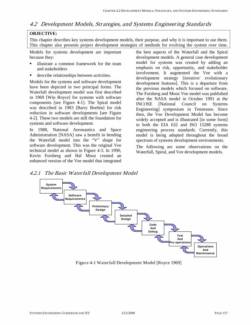
CHAPTER 4.2 DEVELOPMENT MODELS, STRATEGIES, AND SYSTEMS ENGINEERING STANDARDS
SYSTEMS ENGINEERING GUIDEBOOK FOR ITS 12/2/2009 PAGE 157
4.2 Development Models, Strategies, and Systems Engineer ing Standards OBJECTIVE: This chapter describes key systems development models, their purpose, and why it is important to use them. This chapter also presents project development strategies of methods for evolving the system over time.Models for systems development are important because they: illustrate a common framework for the team
and stakeholders describe relationships between activities. Models for the systems and software development have been depicted in two principal forms. The Waterfall development model was first described in 1969 [Win Royce] for systems with software components [see Figure 4-1]. The Spiral model was described in 1983 [Barry Boehm] for risk reduction in software developments [see Figure 4-2]. These two models are still the foundation for systems and software development. In 1988, National Aeronautics and Space Administration [NASA] saw a benefit in bending the Waterfall model into the “V” shape for software development. This was the original Vee technical model as shown in Figure 4-3. In 1990, Kevin Forsberg and Hal Mooz created an enhanced version of the Vee model that integrated
the best aspects of the Waterfall and the Spiral development models. A general case development model for systems was created by adding an emphasis on risk, opportunity, and stakeholder involvement. It augmented the Vee with a development strategy [iterative/ evolutionary development features]. This is a departure from the previous models which focused on software. The Forsberg and Mooz Vee model was published after the NASA model in October 1991 at the INCOSE [National Council on Systems Engineering] symposium in Tennessee. Since then, the Vee Development Model has become widely accepted and is illustrated [in some form] in both the EIA 632 and ISO 15288 systems engineering process standards. Currently, this model is being adopted throughout the broad spectrum of systems development environments. The following are some observations on the Waterfall, Spiral, and Vee development models.
4.2.1 The Basic Water fall Development Model
SystemRequirements
SoftwareRequirements
PreliminaryDesign
DetailedDesign
CodeAnd
DebugTestAnd
Pre-operationsOperations
AndMaintenance
SystemRequirements
SoftwareRequirements
PreliminaryDesign
DetailedDesign
CodeAnd
DebugTestAnd
Pre-operationsOperations
AndMaintenance
Figure 4-1 Waterfall Development Model [Royce 1969]
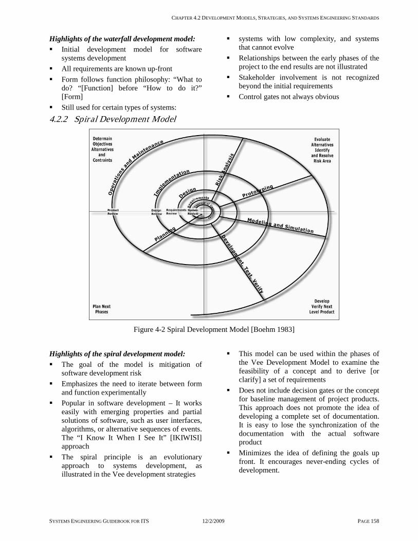
CHAPTER 4.2 DEVELOPMENT MODELS, STRATEGIES, AND SYSTEMS ENGINEERING STANDARDS
SYSTEMS ENGINEERING GUIDEBOOK FOR ITS 12/2/2009 PAGE 158
Highlights of the waterfall development model: Initial development model for software
systems development All requirements are known up-front Form follows function philosophy: “What to
do? “[Function] before “How to do it?” [Form]
Still used for certain types of systems:
systems with low complexity, and systems that cannot evolve
Relationships between the early phases of the project to the end results are not illustrated
Stakeholder involvement is not recognized beyond the initial requirements
Control gates not always obvious
4.2.2 Spiral Development Model
Figure 4-2 Spiral Development Model [Boehm 1983]
Highlights of the spiral development model: The goal of the model is mitigation of
software development risk Emphasizes the need to iterate between form
and function experimentally Popular in software development – It works
easily with emerging properties and partial solutions of software, such as user interfaces, algorithms, or alternative sequences of events. The “I Know It When I See It” [IKIWISI] approach
The spiral principle is an evolutionary approach to systems development, as illustrated in the Vee development strategies
This model can be used within the phases of the Vee Development Model to examine the feasibility of a concept and to derive [or clarify] a set of requirements
Does not include decision gates or the concept for baseline management of project products. This approach does not promote the idea of developing a complete set of documentation. It is easy to lose the synchronization of the documentation with the actual software product
Minimizes the idea of defining the goals up front. It encourages never-ending cycles of development.
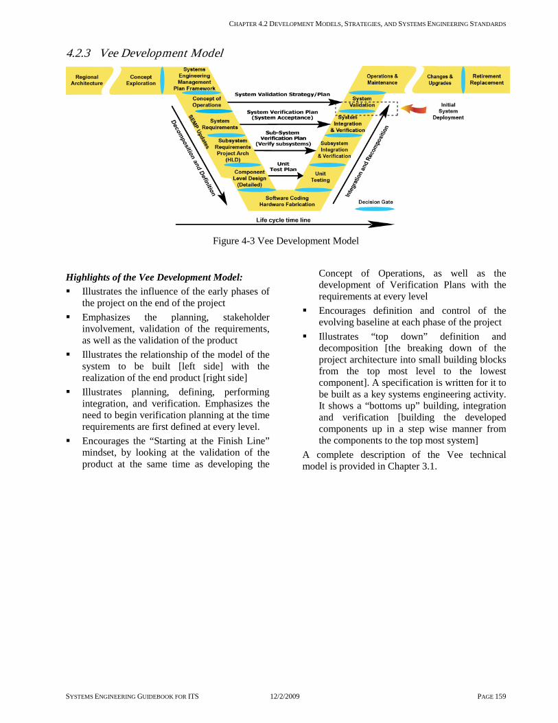
CHAPTER 4.2 DEVELOPMENT MODELS, STRATEGIES, AND SYSTEMS ENGINEERING STANDARDS
SYSTEMS ENGINEERING GUIDEBOOK FOR ITS 12/2/2009 PAGE 159
4.2.3 Vee Development Model
Figure 4-3 Vee Development Model
Highlights of the Vee Development Model: Illustrates the influence of the early phases of
the project on the end of the project Emphasizes the planning, stakeholder
involvement, validation of the requirements, as well as the validation of the product
Illustrates the relationship of the model of the system to be built [left side] with the realization of the end product [right side]
Illustrates planning, defining, performing integration, and verification. Emphasizes the need to begin verification planning at the time requirements are first defined at every level.
Encourages the “Starting at the Finish Line” mindset, by looking at the validation of the product at the same time as developing the
Concept of Operations, as well as the development of Verification Plans with the requirements at every level
Encourages definition and control of the evolving baseline at each phase of the project
Illustrates “top down” definition and decomposition [the breaking down of the project architecture into small building blocks from the top most level to the lowest component]. A specification is written for it to be built as a key systems engineering activity. It shows a “bottoms up” building, integration and verification [building the developed components up in a step wise manner from the components to the top most system]
A complete description of the Vee technical model is provided in Chapter 3.1.
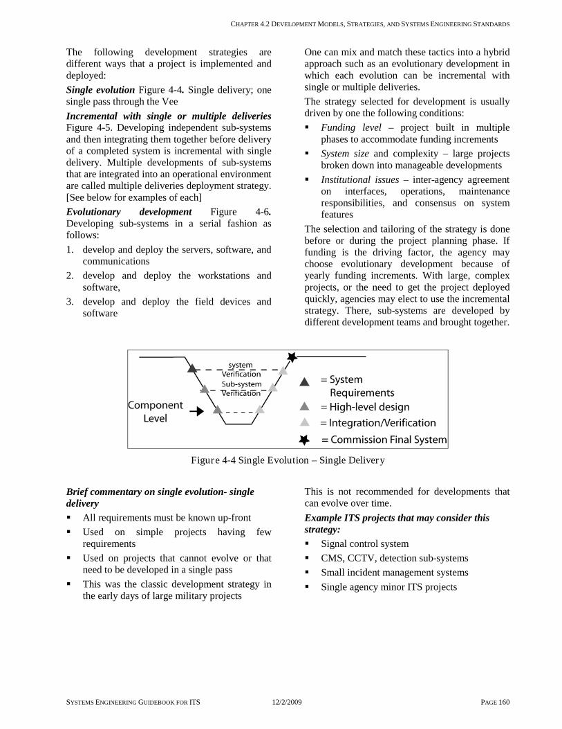
CHAPTER 4.2 DEVELOPMENT MODELS, STRATEGIES, AND SYSTEMS ENGINEERING STANDARDS
SYSTEMS ENGINEERING GUIDEBOOK FOR ITS 12/2/2009 PAGE 160
The following development strategies are different ways that a project is implemented and deployed: Single evolution Figure 4-4. Single delivery; one single pass through the Vee Incremental with single or multiple deliveries Figure 4-5. Developing independent sub-systems and then integrating them together before delivery of a completed system is incremental with single delivery. Multiple developments of sub-systems that are integrated into an operational environment are called multiple deliveries deployment strategy. [See below for examples of each] Evolutionary development Figure 4-6. Developing sub-systems in a serial fashion as follows: 1. develop and deploy the servers, software, and
communications 2. develop and deploy the workstations and
software, 3. develop and deploy the field devices and
software
One can mix and match these tactics into a hybrid approach such as an evolutionary development in which each evolution can be incremental with single or multiple deliveries. The strategy selected for development is usually driven by one the following conditions: Funding level – project built in multiple
phases to accommodate funding increments System size and complexity – large projects
broken down into manageable developments Institutional issues – inter-agency agreement
on interfaces, operations, maintenance responsibilities, and consensus on system features
The selection and tailoring of the strategy is done before or during the project planning phase. If funding is the driving factor, the agency may choose evolutionary development because of yearly funding increments. With large, complex projects, or the need to get the project deployed quickly, agencies may elect to use the incremental strategy. There, sub-systems are developed by different development teams and brought together.
Figure 4-4 Single Evolution – Single Delivery
Brief commentary on single evolution- single delivery All requirements must be known up-front Used on simple projects having few
requirements Used on projects that cannot evolve or that
need to be developed in a single pass This was the classic development strategy in
the early days of large military projects
This is not recommended for developments that can evolve over time. Example ITS projects that may consider this strategy: Signal control system CMS, CCTV, detection sub-systems Small incident management systems Single agency minor ITS projects

CHAPTER 4.2 DEVELOPMENT MODELS, STRATEGIES, AND SYSTEMS ENGINEERING STANDARDS
SYSTEMS ENGINEERING GUIDEBOOK FOR ITS 12/2/2009 PAGE 161
Figure 4-5 Incremental Development with single and multiple deliver ies
Brief commentary on incremental development with single or multiple deliveries Used on large systems that can be divided into
clear sub-systems Works with multiple development teams Used when significant or full system
capabilities can be delivered by the sub-systems one at a time and offer useable capabilities on their own
Need a significant amount of coordination between projects to ensure integration
Risk of finger pointing if different development teams are developing different part of the system
Use of multiple deliveries if each increment can be verified in a stand alone configuration
Use of single delivery would occur if there are dependencies between the increments that need to be verified prior to delivery
Example ITS projects for incremental development with single delivery strategy: Reversible Control lane system Communications infrastructure [major sub-
system] Toll Collections system [Major sub-system,
collection system, tag processing, and enforcement]
This strategy is used for systems or major sub-systems that need to be fully functional before being deployed into service. Example ITS projects multiple delivery strategy: Traffic signal system Central management system followed by: Intersection group 1 [1-5] then Intersection group 2 [6-10] then Intersection group 3 [11-15] Motorist information systems Central management system followed by: Distribution to partner agencies then Internet service providers, etc. Extending additional changeable messages
signs to an existing control system. This strategy is used when partial expansion of an existing system can be deployed over time. It should be noted that in the case of the multiple delivery strategy, the initial sub-system [in this example, the central management system for both the traffic control and motorist information system] needed to be fully functional. It needed to use the single delivery strategy and the expansion of the system elements followed by use of a multiple delivery strategy. .

CHAPTER 4.2 DEVELOPMENT MODELS, STRATEGIES, AND SYSTEMS ENGINEERING STANDARDS
SYSTEMS ENGINEERING GUIDEBOOK FOR ITS 12/2/2009 PAGE 162
Figure 4-6 Evolutionary development
Brief commentary on evolutionary development Used when funding is limited but can be
obtained in multi-year cycles Large projects where not all of the
requirements are known but enough are known to build initial capabilities
Multi-regional systems where stakeholders need to develop systems internally to join with a broader set of stakeholders
Where institutional issues are complex and initial capabilities are needed to resolve them
Projects may or may not provide capability that will go into service. However, they will be building blocks for the next evolution of the system
Evolutionary development is recommended for ITS projects. Example of ITS projects that may consider this strategy: Incident Management System [single or multi-agency
Possible Sequencing: ]
Sub-system 1-The Communications backbone
Sub-system 2-Surveillance [CCTV] Sub-system 3-Changeable Message signs
Sub-system 4-Detection system Sub-system 5-Incident Management Software
Regional Advanced Motorist Information System Possible sequencing: Sub-system 1-The Communications
backbone [agency interfaces and agreements]
Sub-system 2- Detection system Sub-system 3- Data Process software Sub-system 4- Media Interfaces Sub-system 5 Surveillance [CCTV] Sub-system 6-Video interface to Media
Note: Any projects that are done incrementally can be done using evolutionary deployment. In some cases, it may take several evolutions of development before it is ready to be
commissioned into service. The interim evolutions would not be put into service until the whole system is completed. For example, a reversible lane control system may be implemented using evolutionary deployment but would not be commissioned into service until all essential sub-systems have been developed and integrated.
CHAPTER 4.3 RELATIONSHIP TO THE NATIONAL ITS ARCHITECTURE AND FHWA FINAL RULE
SYSTEMS ENGINEERING GUIDEBOOK FOR ITS 12/2/2009 PAGE 163
4.3 Relationship to the National ITS Architecture and FHWA Final Rule OBJECTIVE: This chapter describes the relationship of the National ITS Architecture and the FHWA Final Rule to the ITS systems development process described in this Guidebook. National ITS Architecture The Federal Highway Administration [FHWA] requires ITS projects using federal funds from the Highway Trust Fund [including the Mass Transit Account] to conform to the National ITS Architecture through the regional ITS architecture. The National ITS Architecture provides guidance for the development of ITS projects. It provides a flexible template of interconnections and interfaces to select from at the regional level. In fact, it provides a full range of elements that may be used as ideas [or starting points] for the concept of operations and requirements. The National ITS Architecture is derived from ITS user services. They provide a catalog of features that could be provided by ITS projects for public or private users. Each has associated baseline requirements. They are organized into eight bundles [illustrated in Table 4-1]. Travel and Traffic Management
Emergency Management
Public Transportation Management
Advanced Vehicle Safety Systems
Electronic Payment Information Management Commercial Vehicle Operations
Maintenance & Construction Operations.
Table 4-1 User Service Bundles
The market packages address specific services such as surface street control. They suggest ideas for sub-systems to provide selected services. They are organized into eight service areas [illustrated in Table 4-2]. Archived Data Management
Vehicle Safety
Public Transportation Commercial Vehicle Operations
Traveler Information Emergency Management Traffic Management Maintenance &
Construction Management
Table 4-2 Market Packages
A complete description of the National ITS Architecture is available from the USDOT ITS web site at http://www.its.dot.gov/arch/index.htm. The FHWA Final Rule on Architecture Standards and Conformity [Final Rule] requires the
development of regional ITS architectures and that all ITS projects using federal funds be developed using a systems engineering analysis. The elements of the Final Rule are as follows: 940.5: Describes the requirement to use the
National ITS Architecture to develop regional ITS architectures, and a need for consistency with transportation planning processes
940.7: Describes the specific applicability of the regulation
940.9: Describes the specific requirements for developing regional ITS architecture
940.11: Describes the specific requirements for a systems engineering analysis
940.13: Describes the project implementation requirements
940.15: Describes the requirements for project oversight
23 CFR 940.11 specifies certain activities that are to be performed to accomplish a systems engineering analysis. They are as follows [with notation where this Guidebook will help with each]: 1. Identification of portions of the regional ITS
architecture being implemented. Or, if a regional ITS architecture does not exist, the applicable portions of the National ITS Architecture] [Ch. 3.2.1 in this Guidebook];
2. Identification of participating agencies’ roles and responsibilities [Ch. 3.4.3 Con Ops & Chapters 6 & 7];
3. Requirements definitions [Ch. 3.5.1]; 4. Analysis of alternative system configurations
and technology options to meet requirements [Chips. 3.3.2, 3.5.2, and 3.5.3];
5. Procurement options [Ch. 4.9]; 6. Identification of applicable ITS standards and
testing procedures [Ch. 4.5] 7. Procedures and resources necessary for
operations & maintenance of the system [Ch. 3.7.2].
State and Local Agency Programs State DOT’s lay out the way for transportation agencies to show evidence of meeting the FHWA Final Rule. These procedures will vary from state to state. Most states have offices that specifically

CHAPTER 4.3 RELATIONSHIP TO THE NATIONAL ITS ARCHITECTURE AND FHWA FINAL RULE
SYSTEMS ENGINEERING GUIDEBOOK FOR ITS 12/2/2009 PAGE 164
manage federal funding for local agencies and establish procedures for receiving funding. Often, there are other state and regional regulations that guide project development. They are too numerous to discuss here. Be sure applicable regulations are understood before starting a project. The project will need to be compliant with them.
While this Guidebook has attempted to present a process that is applicable everywhere, there is no guarantee against conflicts between this book and local policies & regulations. In these cases, the local policies and regulations take precedence over this guidebook.

CHAPTER 4.4 RELATIONSHIP TO TRANSPORTATION PLANNING AND INFORMATION TECHNOLOGY
SYSTEMS ENGINEERING GUIDEBOOK FOR ITS 12/2/2009 PAGE 165
4.4 Relationship to Transpor tation Planning and Information Technology OBJECTIVE: This chapter describes the relationship of transportation planning and Information Technology to the project level systems engineering process. For State and local transportation agencies and metropolitan planning organizations, comprehensive planning is a critical element in the development of Intelligent Transportation Systems. Planning professionals take a leadership role in developing regional ITS architecture. It sets the framework for future projects. It also sets the stage for individual projects to be developed and integrated together. The regional ITS architecture is intended to look at the big picture for the region by showing how individual projects will work together. The output of this strategic planning activity provides the foundational input to the project level development. In addition to traditional early planning activities, development of regional and state ITS architecture is strategically performed before either project identification, or programming into the Transportation Improvement Plans [TIP] for funding. Those roles will be covered in Chapter 3.2.1. Participation by planning professionals in the early stages of system project development is important. Their differing perspectives on resources, budget, and timeline, help strengthen the Concept of Operations documentation by providing varied viewpoints regarding the system’s usage. These roles will be covered in Chapter 3.4.3. The following is a comparison of roles played by the traditional DOT divisions in capital ITS infrastructure projects as compared to their roles in ITS system developments. The role that the planning department currently plays in the development of capital ITS infrastructure projects is the same as the use of the left side of the Vee Development Model for ITS system developments [See Chapter 3.1]. Only, it’s performed at higher [regional or program] levels. Stakeholder’s needs are identified. The system and problem space is modeled. Alternatives are explored. All requirements for the project are defined. After the projects are defined by planning, they are placed into the TIP. Upon completion of this strategic process, a transitional hand-off to Project Development occurs. Then, Planning becomes minimally involved in the design and implementation of the individual projects. In concert with Traffic Operations,
Project Development designs and implements the project. Traffic Operations manage the project. The Maintenance division maintains the facility and supports traffic operations. These roles are well defined. A different pattern surfaces for ITS system development projects. The Planning division provides their traditional role in early project planning, including the development of the regional ITS architecture. From this point, there is often an activity undertaken [usually by the Traffic Operations division] to perform a feasibility analysis. Then, Traffic Operations addresses the more specific process steps that make up the left side of the Vee Development Model. These include: 1. identifying the more specific needs of the
system user 2. breaking down the definition of system and
sub-system requirements. As was stated earlier, these definition steps before actual design are similar to traditional Planning strategic steps [except at a more specific project development stage]. This should not exclude Planning’s participation. Even though the traditional handoff has occurred, planning stays involved through the user needs stage, Concept of Operations. This will be further discussed in Chapter 3.4.3. Information Technology departments have also become more involved with the implementation, deployment, and maintenance of these systems. They are introduced to the project with the development of a benefits analysis. Their requirement is discussed in Chapter 3.3.2. Additionally, the Maintenance division [who maintains the field elements] should be involved in the early stages of definition. In summary, for ITS developments, it is important that an integrated view be adopted for the development, operations, and maintenance of these systems. This integration must have a clear and inclusive interface between Planning and ITS system development. Table 4-3 illustrates the point of interface that exists between Planning/Regional ITS Architecture and Systems- Development/Project Development, and the bridge between them.

CHAPTER 4.4 RELATIONSHIP TO TRANSPORTATION PLANNING AND INFORMATION TECHNOLOGY
SYSTEMS ENGINEERING GUIDEBOOK FOR ITS 12/2/2009 PAGE 166
Table 4-3 Br idging Between Planning and Systems Development at the Project Level
Planning Systems Development Comments
Regional ITS Architecture Project Development Bridge between Planning and Development
Inventory Concept Exploration and Benefits Analysis
Concept of Operations
Existing systems and legacy interfaces
Stakeholder Identification Concept Exploration and Benefits Analysis
Concept of Operations
Starting point… additional project stakeholders need to be added, such as: maintenance, operator, and managers.
High Level Needs/Services Concept Exploration and Benefits Analysis
Concept of Operations
Goals and objectives for the regions. Specific project level goals must support these
Area of Coverage Concept of Operations Forms the boundary for the projects of the architecture
Operational Concept Concept of Operations Identifies the initial roles of the stakeholders
High Level Requirements Concept Exploration and Benefits Analysis
Concept of Operations Requirements Development
Starting point for requirements. These requirements will need to be refined for each of the projects making up the regional ITS architecture
Interconnect/Information Flows
Concept of Operations
Requirements Development
High Level Design
Provides the initial set of interfaces for the projects. These will need to be refined at the project level based on the tailoring of the service
ITS Standards Requirements Development
High Level Design
Identifies a set of candidate ITS standards that can be used for interfaces
Project Sequencing Project Planning
Concept of Operations
Defines the evolutionary path
Interagency Agreements Concept of Operations
High Level Design
Defines stakeholders’ role in operations & maintenance, Interface Control Documents

CHAPTER 4.5 RELATIONSHIP TO ITS STANDARDS
SYSTEMS ENGINEERING GUIDEBOOK FOR ITS 12/2/2009 PAGE 167
4.5 Relationship to ITS Standards OBJECTIVE: This chapter identifies the relationship between this Guidebook and ITS standards. The focus of this chapter is on identifying key systems engineering process standards and other related ITS standards. This chapter will briefly discuss evolving ITS protocol and equipment standards. Why Use ITS Standards? Don’t reinvent the wheel: Use of equipment standards [Dynamic Message Sign, for instance] mean that requirements will not need to be developed from scratch. However, be aware that equipment standards may not keep up with advances in technology. Avoid early obsolescence: By gradually migrating field devices to ITS standards compliant devices the system will be moving in the direction the industry is going. Obtain a choice of vendor: Products conforming to an ITS standard can be inter-changeable with products from other vendors. However, inter-changeability is hindered by vendor specific features that go beyond the standard, or by partial implementation of a standard. Multi-point control of devices are going in the direction of IP-based networks. Not only will this put all devices on a single network; any center on the network can access and control any device. This allows the centers to back up each other in case of failure or operational downtime. Potential Benefits of Standards to Systems Engineering Processes If a system is being developed that has components covered by mature ITS standards and the existing ITS standard supports your operational concept; then, the use of ITS standards can be of considerable benefit to many [if not most] of the systems engineering processes described in this Guidebook. Obvious examples include: High Level Design and Component Level
Detailed Design: If an ITS standard [example: a Dynamic Message Sign] can support your requirements, then use of such a standard eases the design tasks and allows the use of predefined proven components
Hardware/Software Development: Use of ITS standard components such as the use of any off-the-shelf product, will reduce the design effort
Integration and Verification: If the chosen ITS standards are mature, then both integration and verification efforts will be easier. On the other hand, if the ITS standard
is not mature, or has not been used before, the effort to prove the product matches the standard can be difficult
Risk Management: Use of a proven product built to a mature ITS standard will reduce development risk in a project
Procurement Options: Use of ITS standards will make it easier to specify the product needed for the project and allow multiple vendors to compete to provide the same standard product
Standards are widespread in the transportation industry and are generally developed for one of two reasons: to improve interoperability or to stimulate competition. For ITS, a primary emphasis of the standards being developed is on the interoperability of systems and the interchangeability of sub-systems and components. This leads to easier system integration and smoother coordination among systems
What does FHWA Final Rule [23 CFR 940.11] say about the use of ITS Standards? FHWA Final Rule [23 CFR 940.11] requires that “All ITS projects funded with highway trust funds shall use applicable ITS standards and interoperability tests that have been officially adopted through rulemaking by the DOT.” As of the date of this writing, while the DOT recommends judicious use of the available standards, none of them have been officially adopted through rulemaking. The FHWA Final Rule also expects the regional ITS architecture to identify ITS standards supporting regional and national interoperability. The Final Rule expects consistency between the regional ITS architecture and any related projects. NTCIP Standards Development One ITS standards effort is being conducted by the National Transportation Communication for ITS Protocol, or NTCIP. These standards identify protocols and message sets to be used Center to Center, Center to Roadside, and Vehicle to Roadside. It is a joint standardization project of the American Association of State Highway and Transportation Officials [AASHTO], the Institute of Transportation Engineers [ITE], and the

CHAPTER 4.5 RELATIONSHIP TO ITS STANDARDS
SYSTEMS ENGINEERING GUIDEBOOK FOR ITS 12/2/2009 PAGE 168
National Electrical Manufacturers Association [NEMA], with funding from the U.S. Department of Transportation [USDOT]. [See NTCIP 9001 National Transportation Communications for ITS Protocol – NTCIP Guide Version 3 at Website http://www.ntcip.org ] Other ITS Standards Activity Standards development organizations at the national level that are working on ITS standards also include: American National Standards Institute [ANSI], http://www.ansi.org [general communications] American Society for Testing & Materials [ASTM], http://www.astm.org [Vehicle to Roadside] Institute of Electrical and Electronics Engineers [IEEE], http://www.standards.ieee.org [Center to Center transit and incident management] Society of Automotive Engineers [SAE], http://www.sae.org/topics/itsinits.htm [Center to Center and Vehicle to Roadside] Documentation and Process Standards Activity Another area of standard development that is of use to the systems engineer involves documentation standards and systems engineering process standards. Systems engineering document and process standards offer the systems engineer good advice in the following areas: Systems Engineering Process
Institute of Electrical and Electronics Engineers, IEEE Std. 1220-1998 IEEE Standard for Application and Management of the Systems Engineering Process Electronics Industries Alliance, EIA 632 Standard Processes for Engineering a System
Concept of Operations Document [see Chapter 3.4.3
IEEE 1362 IEEE Guide for Information Technology – System Definition – Concept of Operations Document
]
Concept of Operations Document [see Chapter 3.4.3]
American National Standards Institute / American Institute of Aeronautics and Astronautics, ANSI / AIAA G-043-1992 Guide for the Preparation of Operational Concepts Documents
Requirements Specifications [see Ch. 3.5.1] IEEE STD 1233 IEEE Guide for Developing System Requirements Specifications
Configuration Management [see Ch. 3.9.6] EIA 649 National Consensus Standard for Configuration Management
Technical Reviews and Audits [see Ch.3.9.10] IEEE 1028-1988 Standard for Software Reviews and Audits
Software Architecture Design [see Ch. 3.5.2 and 3.5.3]
IEEE 1471-2000 Recommended Practice for Architectural Description of Software-Intensive Systems
Independent Verification and Validation [see Ch. 3.6.3 and 3.7.1]
IEEE 1012-1998 Standard for Software Verification and Validation
System Modeling Standards Activity Over the years there have been many attempts to develop modeling approaches to help with system and software design, including: Unified Modeling Language [UML] - This is
a language for specifying, visualizing, constructing, and documenting the design of software. The standard for UML is maintained by the Object Management Group. Information on UML is available at their web site, http://www.omg.org.
Integrated Method for Information Modeling [IDEF] - Another method for modeling processes is called IDEF. This technique is used in the Guidebook to model the processes described in Part 4. Information on IDEF can be found at http://www.idef.com.

CHAPTER 4.6 SYSTEMS ENGINEERING SUPPORT ENVIRONMENT
SYSTEMS ENGINEERING GUIDEBOOK FOR ITS 12/2/2009 PAGE 169
4.6 Systems Engineer ing Suppor t Environment OBJECTIVE: This chapter describes what the systems engineering environment needs to support the systems engineering capabilities within the agency. This chapter describes the basic support needs for the systems engineering environment: the development of a documented process, process improvement, training and capacity building, technology re-use, and systems engineering support tools for carrying out the documented process. Keys to success for ITS projects are management support and an environment that promotes the use of the systems engineering process for developing ITS projects. Well-defined and documented processes, tools, training, and application of technology across agency projects are important to the success of projects. The following elements describe this environment. The systems engineering environment needed to support successful project development includes the following key elements: Defined and documented process and process improvement Documented systems engineering processes must support the organization’s internal goals and objectives. It is recommended that a documented set of systems engineering processes be created. This Guidebook would be a good starting point for those procedures. The use of a common set of processes will benefit ITS, as the established set of processes has for capital projects. Once the systems engineering processes have been developed, they will provide a common framework by which ITS projects are carried out. This will benefit the agency in the utilization of their resources and their ability to efficiently pull together teams for projects. In addition to these processes, a method is needed to assess how well the process is accomplishing its intended purpose. Then, adjust the process continuously to improve its effectiveness. [See process improvement]. Capacity building and training development Training will benefit an agency in the development of capabilities in key systems engineering topics and should be part of the systems engineering environment. This training includes both in-house and contracted training courses. Training in contracting, project management, systems engineering, configuration management, risk management, and maintaining the regional architecture are some of the basic
courses that are recommended for ITS practitioners. Other specialized courses, such as requirements engineering, reverse engineering, modeling and simulation, architecting, and software and hardware design, should be considered for staff that will be focusing in these areas. Since technology is changing, refresher classes in all of these areas are recommended. Technology transfer Organizations can benefit and optimize the use of technology by being aware of the technologies that are in use throughout the organization. Organizations must assess vendors to ensure their ability to produce quality products that will be supportable, maintainable, and affordable for the projects. Standardization is a way to reuse technology and minimize the risks of new developments. Systems engineering support Systems engineering support provides the tools, processes, and training to enable various aspects of systems engineering to be performed. For example, these tools may include: requirements management and modeling tools, test beds, simulators, training, office space, documented processes, software, and test equipment. Process improvement An organization should provide for the continuous process improvement to fine tune the processes over time. Initially, an organization will put into place a set of processes and procedures and use a test case project to wring out the steps in the process. Then, it will re-write [or modify] the areas in the processes that are weak or too rigid and costly. The process may be relaxed to fit the real world situation. Over time, this process becomes part of the support environment and is continuously improved with lessons learned on each project.

CHAPTER 4.7 COMMON AGENCY SYSTEMS ENGINEERING ACTIVITIES
SYSTEMS ENGINEERING GUIDEBOOK FOR ITS 12/2/2009 PAGE 170
4.7 Common Agency Systems Engineer ing Activities OBJECTIVE: This chapter describes agency systems engineering activities, that impact ITS, currently practiced. These activities exist in some form within most agencies. The intention is that this Guidebook will leverage these activities, to complement and not duplicate, or be in conflict with these processes. The following is a description of some common agency activities that can be leveraged for the systems engineering processes. Configuration Management [CM] activities Agency level configuration management is a function that is responsible for monitoring and approving changes to the hardware in the field, for example, signal controllers and communications. In some agencies this may come from the Information Technology department, or it may be called asset or resource management. This could be leveraged to perform configuration management for Intelligent Transportations Systems [ITS]. Their processes and procedures would need to be augmented to manage ITS systems development and operations & maintenance. If these procedures are not in place, a configuration management capability at the agency level will need to be developed. Standardization Applicable agency standards from the Information Technology department should be leveraged for the systems engineering process. These standards may constrain the developers on technology choices, such as databases, software applications, workstations, and servers. This may be of great benefit when purchasing software licenses, workstations, or choosing a database and operating systems. It also may have a disadvantage in that ITS applications will be constrained to these choices and preclude better or more efficient solutions for the designers. Feasibility process Agencies often evaluate alternative solutions to choose the best cost/benefit solution and justify the business case for a project. These activities may have a strict internal processes defined. If available they will be used for their ITS projects during the early planning stages. For example, the State of California uses the Feasibility Study Report for the justification of IT and ITS projects. The products from this process may be used for the system engineering process for the project, such as the goals and objectives, vision, stakeholder lists, and key performance measures. Again these processes may need to be tailored to satisfy agency policy requirements.
Information Technology process and guidance activity The Information Technology [IT] department of an agency may have resources that can be leveraged for Intelligent Transportation System developments. Most IT departments have development processes in place that focus on similar information technology applications. These same processes may be adapted for ITS. Since systems engineering integrates different disciplines, the leveraging of Information Technology processes needs to be evaluated using other domain expertise such as traffic operations. It is critical that domain expertise is involved with the tailoring of these processes. Systems engineering capabilities for small and large agency organizations For a small local agency implementing a single ITS project, systems engineering may be minimal [See Ch. 4.10]. It may be adequate to have the system’s owner take some training in systems engineering fundamentals and then tailor, implement, and manage the SE processes by themselves. Another option is to hire a consultant that is experienced in systems engineering [See Ch. 4.9] to perform these activities, or get available assistance from the State DOT and/or the FHWA resource centers. This support environment may be temporary and only needed for a specific project. Larger organizations, for example an MPO or State Transportation Agency, will benefit from an established systems engineering support environment and leveraging from the existing agency activities across all of the projects. This “umbrella” systems engineering experience within an agency can lead to the following services: sharing of appropriate skills needed to carry
out the roles and responsibilities of each project
sharing experiences through lessons learned independent technical reviews established common approach, sharing
technology, tools, and re-use of project products

CHAPTER 4.8 SYSTEMS ENGINEERING ORGANIZATION
SYSTEMS ENGINEERING GUIDEBOOK FOR ITS 12/2/2009 PAGE 171
4.8 Systems Engineer ing Organization OBJECTIVE: This chapter describes typical systems engineering organizations and the role these organizations play in the development of ITS. What makes an effective organization? Effective systems engineering requires an integrated organizational structure with the following characteristics: is flexible to support a range of project types facilitates clear communications has defined roles and responsibilities can be scaled to small or large project teams related activities are together as a team
[organizational entity] Because a system is being developed, the various disciplines that make up these teams, [For example hardware, software, or human-machine interface] are not independent of one another. Cross-coordination must be ongoing throughout project development. Continuing communication across disciplines is an essential function of the project organization for successful system development. Specifically, the key criteria for an effective system management organization as adapted from Wilton P. Chase’s Management of Systems Engineering are: facilitate communications streamline controls simplify the paper work types of organizational structures relationships to consultants and vendors The following is an explanation of each. Facilitate communications Few of the problems that arise in developing a system can be solved by a single discipline. Each provides a way of looking at the system. Complete understanding requires integrating these perspectives. This system view is an ongoing need. Therefore, the various team members must coordinate as the system is being developed. They must understand the viewpoint of the others and communicate in a language understandable to all. Streamline controls A clear statement and understanding of the level of detail to be controlled at the project level makes management more efficient. It keeps the managers from slipping into too much detail emanating from their respective backgrounds. The
process steps in Chapter 4.10 give guidance on how to tailor the process appropriately. Simplify the paperwork Standardized documentation is essential for efficient system management to record and transmit analyses, plans, and designs. During much of the systems engineering process, documentation is the only product. The system design is described only by specification. The following chapters of the Guidebook provide guidelines for developing documents appropriate to the scale and complexity of the project at hand. Types of organizational structures Functional One common approach is a functional configuration. Here each functional specialty or discipline is assigned to individual organizational entities. As an example, consider a systems engineering team who performs all systems engineering across all projects. This works best for small projects, where the team members may be working on several projects at once. Communications problems can occur for larger projects when sub-system teams are created. The risk is the sub-system teams may optimize for the sub-systems, not the system. Also, integration may be difficult since the pieces have been developed independently. This means that frequent cross-disciplinary communication and consideration of the system-level issues are essential. Project The other approach is centered on projects, not disciplines. All those working on a project, no matter what their specialty, will report [possibly indirectly] to the project manager. This works only if the project is so large and long-term that the specialists can devote themselves to it for an extended period. Matrix A hybrid approach, the matrix management structure, exists when team members report to both project and functional management. This approach is effective for large, long-term projects. The Project Office approach, calls for project management, systems engineering, and design teams to be organized by project, and request project support from the functional staff as needed. This works for a moderate sized project, when only the key individuals devote full time to

CHAPTER 4.8 SYSTEMS ENGINEERING ORGANIZATION
SYSTEMS ENGINEERING GUIDEBOOK FOR ITS 12/2/2009 PAGE 172
the project. The specialists work on multiple projects. Integrated Product Team [IPT] this team consists of both agency and contractor representatives. They work together to develop the system that meets the project’s needs. In a large project, there are often mirror functions in the agency and contractor teams. For example, each has a program manager and a systems engineer. They work closely with their counterpart in the IPT. Further, representatives of each of the disciplines are a part of the IPT to ensure essential cross-discipline communication. Additionally, IPT’s may be formed to address key cross-discipline issues, such as cost of ownership, overall system performance, or configuration management. Example organizational roles Figure 4-7 is an example of roles that are generally required for a successful systems engineering organization [adapted from Chase]. This may appear frighteningly complex, especially for an agency that typically does small projects. The important thing is that each box represents a role, not a department or an individual. A simple project may only require two people: a project manager and a systems engineer. Administrative functions assist on an as-needed basis. For larger organizations that manage more complex projects, this is a template for structuring groups with like activities together while
maintaining system-level oversight and coordination. There are three major activities in the organization: project management, systems engineering, and project control. Project management is concerned with planning and execution. Project control tracks the effort relative to performance, cost, and schedule goals. The same person may assume these two roles. Systems engineering is responsible for design, implementation, and verification. Relationship to consultants and vendors There is no single, correct, organizational structure. It needs to be tailored for each team based on existing structures and capabilities within the agency. It should take effective advantage of in-house expertise, existing working relationships, and communication paths. There are no standard roles for agencies and contractors. Agencies can [and often will] develop their own software, for example. Similarly, an agency may choose to outsource oversight activities. The only caveat is that there are certain activities which can only be performed by the agency. These key activities are listed for each step in the process throughout Chapter 3. The keys to a successful team that includes consultants are: appropriate roles and frequent, frank communications.
ConfigurationManagement
QualityAssurance
ContractManagement
Finance
SystemDesign
InterfaceControl
Analysis,& Evaluation
Integration& Test
SystemsEngineering
Performance,Cost,
Schedule
DataManagement
Administration,Support
ProjectControl
ProjectManagement
•PrimeEquipment•SupportEquipment•Facilities•Software•Procedures•Training•Logistics
•Contractors•Vendors
•RequirementsAnalysis•PerformanceEffectiveness•SE Control andEvaluation
•EngineeringTest•QualificationTest•SystemIntegration andOperations Test
Figure 4-7 Example Organization
CHAPTER 4.9 PROCUREMENT OPTIONS
SYSTEMS ENGINEERING GUIDEBOOK FOR ITS 12/2/2009 PAGE 173
4.9 Procurement Options OBJECTIVE: This chapter describes various procurement options, types, and techniques available for the acquisition of Intelligent Transportation Systems [ITS] and some examples of how they can be used. The following are options that can be used for obtaining services to develop ITS projects. Agencies with an internal pool of technical resources may elect to develop the entire system in-house. Most agencies will use a combination of in-house, system managers, Systems engineering technical assistance, and oversight for ITS projects and then procure under a separate contract, the development and integration services. In-house Development System’s owners who elect to use the internal resources and capabilities of the organization to perform the development activities should use the processes described in this Guidebook. Internal agreements should be written and signed between the system’s owner and development teams as though they were procured from the outside. In addition, there should be an independent review [by another division, agency, or independent consultant] of the products and activities. Even though the development is done internally, an independent review team is recommended in order to provide a sanity check on the development. This will build confidence in the project and help identify and manage project risks. Contracted Services The following is a brief description of two basic classifications of procurement common for building transportation capital projects: Engineering and Design Services: In
traditional infrastructure construction, this type of procurement is used for the planning and development of the Plans Specifications & Cost Estimate [PS&E]. The contractor selection [for this type of procurement] is based on qualifications.
Construction services: In traditional infrastructure projects, construction follows PS&E. It is the installation phase of the project. Construction contractor selection is based on the bid price.
In this Guidebook, reference is made to Consultant, System Manager, Systems Engineering Technical Assistance, System Integrator, and Independent Verification & Validation [IV&V]. These contracted services are used to carryout various aspects of ITS project
development. It is recommended that the Engineering & Design Services procurement option be used to contract for these services. This allows the agency to select the appropriate team based on their qualifications, not on the lowest price. Construction services [low bid process] should continue to be used for routine ITS field elements [poles, cabinets, pull-boxes, and installation.], building the TMC, or standard items such as Model 170 or 2070 controllers with standard modules. The Construction services option is NOT recommended for the other system development services noted above. That includes specialized hardware and software procurement or development and integration.
Some key procurement issues and techniques related to ITS developments
The following is a brief description of the primary types of contracts used in ITS procurements, plus relevant issues and techniques associated with each. Fixed Price: System’s owner contracts a single price for all products and services to implement the project. This is sometimes referred to as low bid or lump sum. Fixed Price is usually associated with the low bid used with Construction procurements. This type of contract transfers the project risks to the contractor. When there is a cost overrun, the contractor absorbs this overrun. If they perform better than planned, the contractor’s profit is higher. In ITS developments, the System’s owner who uses a fixed price contract needs to know exactly what is expected and clearly specifies it to the contractor. Standard performance specifications must be in place and special provisions documented for the work to be contracted. If not, the contractor can interpret the vague scope of work in their favor to meet profit goals [e.g. reduced documentation, testing, proprietary solution]. Since all risks are absorbed by the contractor, a fixed price bid will be higher to reflect this uncertainty. Cost-reimbursement [Cost plus]: System’s owner reimburses the contractor for labor, material, overhead, administration costs, plus a fixed fee.
SECTION 4.9 PROCUREMENT OPTIONS
SYSTEMS ENGINEERING GUIDEBOOK FOR ITS 12/2/2009 PAGE 174
Cost-reimbursement type contracts are used where there is a high level of project risk and uncertainty. With this type of contract the risks reside primarily with the system’s owner. The contractor gets reimbursed for all of his costs. Additional work performed due to changes or rework, entitle the contractor to get paid for this additional effort. The overall budget is managed by the system’s owner. This type of contract is recommended for the system definition of hardware & software development where there is the risk of stakeholder changes to the system. A variation on this type of contract, which has been used in the past for ITS projects, is a combination of a cost-reimbursable [cost-plus] with a cost cap on the total project. The contractor cannot exceed this and is responsible to manage to it [contractor has the project risks]. This is essentially a fixed price contract. ITS projects are not well defined in the early stages of system definition; there are many unknowns and risks of stakeholder changes. In these cases this variation on the Cost-reimbursement [Cost plus] option is not recommended. Time and Materials [T&M] type of contract: System’s owner pays an hourly rate which includes all profit and overhead. The materials are billed separately. This type of contract is similar to the Cost-reimbursement [Cost plus] type of contract. Except, the contractor rolls all labor, overhead, and fees into an hourly rate. The system’s owner only sees this rate. Materials are paid separately. This type of contract is recommended when the risk of stakeholder changes to the system is high or stakeholder involvement requires an unknown number of meetings, reviews, and iterations on definition & design.
Task ordering: This is a technique for managing a project that has a number of tasks but the detailed scope of each is not well specified upfront. This can also apply where the system’s owner has multiple contractors and consultants under a single contract. This technique allows a great deal of flexibility to the system’s owner for systems development. The following are examples of how task ordering can be used for ITS developments. Each phase of the project can be executed
with a sequence of task orders. For example, the task would be for the development of a concept of operations, or the development of the system requirements. At the end of the task the system’s owner may elect to issue another task to carry the work forward or use a different consultant or contractor.
Another example is the development of alternate designs from multiple development teams. Each design is evaluated when complete. The best design or combination is selected for implementation. For example, the National ITS Architecture development was accomplished using four [4] independent teams working concurrently. At the end of this phase, the best aspect of each was integrated together into a single architecture that we use today.
For projects where there is an overlap between a consultant phase and the development team’s phase of work, a task order can be used to bring a development team into the project early. The system’s owner would get support during the earlier phase activities without being committed to the development team for the next phase of work.

SECTION 4.10 ESTIMATING THE AMOUNT OF PROCESS NEEDED
SYSTEMS ENGINEERING GUIDEBOOK FOR ITS 12/2/2009 PAGE 175
4.10 Estimating the Amount of Process Needed OBJECTIVE: This chapter provides guidance on how much process [or project tailoring] is needed for ITS projects. It describes ways to assess the degree of formal process needed to deliver the system with the required level of quality; assures that the project will meet the expectations of maintainability, documentation, and functionality; and address all the key risk areas.
Figure 4-8 Degree of Formal Systems Engineer ing
How much process is needed for a given project? This is a difficult question to answer but one that needs to be addressed. Tailoring of the systems engineering process is a key initial activity for the systems engineer. It is not always based upon a single factor [cost or size]. The amount of formal process is a question that cannot be fully answered quantitatively. Engineering judgment, experience, and institutional understanding are needed to “size up” a project. As the project is being carried out, the focus should be on the end-product to be delivered. It should not be on the process to follow. In the ideal world the product delivered should carry just enough systems engineering process, documentation, and control to produce it at the desired quality level. No more and no less. There is a balance that needs to be kept and continually monitored. Illustrated in Figure 4-8 is a notional graph that depicts this balance. Mr. Ken Salter1
1 LA Chapter INCOSE presentation 2003, JPL Pasadena
adopted this analysis for systems engineering. It shows that we need to look at each ITS project and assess the amount of systems
engineering that needs to be done. This is the tailoring process that a systems engineering team performs as part of project planning. The amount of process needed for a project depends upon the following factors: Project risks System complexity Number of stakeholders Number of interfaces Decisions needing to be made Existing documentation As a starting point for estimating the percent of effort, the Table 4-4 can be used.
Table 4-4 Estimate of Percent of Effort in SE Planning Definition Design Implementation Integration/
Verification 10% 15% 20% 30% 25%
The following two examples are used to illustrate the amount of systems engineering needed in a very simplistic way. In Chapter 4.10 there is an elaboration of each of these examples.

CHAPTER 4.10 ESTIMATING THE AMOUNT OF PROCESS NEEDED
SYSTEMS ENGINEERING GUIDEBOOK FOR ITS 12/2/2009 PAGE 176
Example 1: Adding field elements to an existing system. [See Chapter 4.11.1 for more details] The following is a brief description of the example project: A $10 million project will add 30 full matrix changeable message signs [assuming $330K per sign] to an existing system which has five of these same signs already deployed. No other changes to the central or field equipment are needed [including no required changes to the communications network]. The system was initially designed to accommodate these additional signs so no additional software is needed. The assumptions for this example is as follows: 1. The communications and power for the signs
have already been deployed under a previous construction project
2. the initial system is completed and the system is working
3. the effort is limited to deploying the signs, installing the poles and foundations, procuring the controllers, and wiring the controllers to the signs
4. only configuration information about the signs needs to be added at the host by the user
5. the construction costs have been included in the cost of the signs
6. optimum locations have been identified This example represents the adding of more field equipment [changeable message signs, cameras, traffic signals, and ramp metering] to an existing system. In this example, the assumptions are that the existing system was originally designed to accommodate the added elements and no additional design work is needed. In this example, the project risks are fairly low, there is a minimal number of decisions to be made, project complexity is low, common inter-faces have been established, and minimal stakeholder issues exist. One may assume the same documentation which implemented the original system is adequate for the expanded system. In this example, little systems engineering is warranted, other than a cursory review of system engineering products already delivered. However, it is recommended that a review of the existing documentation be done to ensure no adverse effects will occur when the additional elements are added to the system. Example 2: Builds on the first example but adds a new requirement for sharing control with another partner agency. [See Chapter 4.11.2 for
more details] The following is a brief description of the example project: This new functionality was not pre-planned
and assumes new software will be developed and integrated into the existing system. The initial estimate for the software is approximately $500K for development and integration. Existing control software was not designed for this requirement and although the cost estimate is low with respect to example 1, it injected typical institutional issues that ITS projects face in developing regional systems. The point of this example is that the requirement for sharing adds a significant risk to the project.
This example has introduced additional risks, additional decisions to be made, a broader set of stakeholders, and added complexity in functionality and interfaces. Further, there is the risk that the existing system cannot be easily changed to accommodate the new functionality. In this example the application of systems engineering is warranted to address these issues. It is interesting to observe that, even though the cost estimate for this example adds only 5-6% more to example 1, the issues mentioned above plus the addition of a custom development of software and changes to the existing system drove the need for more formal systems engineering. The message is that cost alone is not a driver in defining the level of required systems engineering. Defining the appropriate level requires looking at a number of inter-related issues. Each project is unique. We recommend that each project be assessed on its own merits as to the amount and degree of formal systems engineering that is needed. This tailoring is a systems engineering responsibility that occurs at the onset of each project. Example areas of project tailoring Trade studies on the number of options to
consider Content of COTS products in the system [the
caution is that if the vendor is not qualified this may be a very high risk]
Degree to which the system under development is similar to another.
Number of Technical Reviews Project tailoring is done as part of the project planning. It is included in the Systems Engineering Management Plan [SEMP] which is described in Chapter 3.4.2.
CHAPTER 4.11 EXAMPLE PROJECTS
SYSTEMS ENGINEERING GUIDEBOOK FOR ITS 12/2/2009 PAGE 177
4.11 Example Projects The following tables describe the degree of systems engineering that would be applied to three example ITS projects. These tables also provide a guide on the level of effort required for each phase of the project. It should be noted that these are estimates and that each project [even if they are similar to the ones listed] will need to be evaluated on its own merits. The following is a brief description of the projects listed in the following tables:
Project Example 1 Adding field elements to an existing system: this example adds changeable message signs to an existing system. The point of this example is to show that cost is not necessarily a driver in the amount of systems engineering needed. A 10 million dollar project may need less systems engineering than a $500K project. Also, this example applies to field cameras, ramp metering, intersection controllers, or detection.
Project Example 2 Adding new functionality to an existing system: this example builds on example 1 - the changeable message signs, we add another requirement of sharing control of the signs with a partnering agency. In this example,
the existing control software was not designed for this requirement and injected typical institutional issues that ITS projects face in developing regional systems. The point of this example was that the requirement for sharing adds significant risk the project. Even though the estimated cost of the software is small compared to the cost of the changeable message signs, the project risk is driven by the upgrade to the controlling software and the institutional issues. This example also applies to the sharing of field devices, such as cameras, signal systems, or the integration of bus priority with signal systems.
Project Example 3 implementing a new central management system: This example upgrades a signal system. This is a typical project. It provides a good example of the nominal amount of systems engineering required when using a COTS product.
These are typical activities and estimates of effort. This should not be taken as a “script” to follow. These projects, in any given environment, may require more or less systems engineering effort.
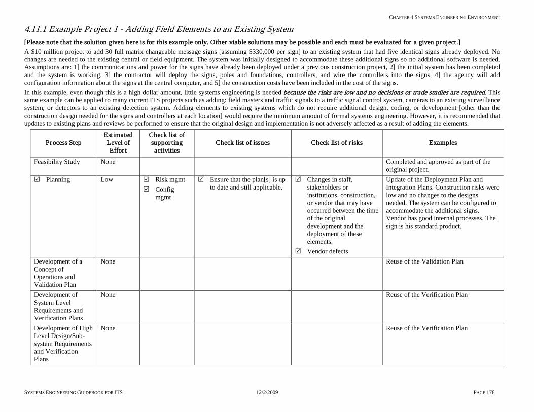
CHAPTER 4 SYSTEMS ENGINEERING ENVIRONMENT
SYSTEMS ENGINEERING GUIDEBOOK FOR ITS 12/2/2009 PAGE 178
4.11.1 Example Project 1 - Adding Field Elements to an Existing System [Please note that the solution given here is for this example only. Other viable solutions may be possible and each must be evaluated for a given project.] A $10 million project to add 30 full matrix changeable message signs [assuming $330,000 per sign] to an existing system that had five identical signs already deployed. No changes are needed to the existing central or field equipment. The system was initially designed to accommodate these additional signs so no additional software is needed. Assumptions are: 1] the communications and power for the signs have already been deployed under a previous construction project, 2] the initial system has been completed and the system is working, 3] the contractor will deploy the signs, poles and foundations, controllers, and wire the controllers into the signs, 4] the agency will add configuration information about the signs at the central computer, and 5] the construction costs have been included in the cost of the signs. In this example, even though this is a high dollar amount, little systems engineering is needed because the risks are low and no decisions or trade studies are required. This same example can be applied to many current ITS projects such as adding: field masters and traffic signals to a traffic signal control system, cameras to an existing surveillance system, or detectors to an existing detection system. Adding elements to existing systems which do not require additional design, coding, or development [other than the construction design needed for the signs and controllers at each location] would require the minimum amount of formal systems engineering. However, it is recommended that updates to existing plans and reviews be performed to ensure that the original design and implementation is not adversely affected as a result of adding the elements.
Process Step Estimated Level of Effor t
Check list of suppor ting activities
Check list of issues Check list of r isks Examples
Feasibility Study None Completed and approved as part of the original project.
Planning Low Risk mgmt Config
mgmt
Ensure that the plan[s] is up to date and still applicable.
Changes in staff, stakeholders or institutions, construction, or vendor that may have occurred between the time of the original development and the deployment of these elements.
Vendor defects
Update of the Deployment Plan and Integration Plans. Construction risks were low and no changes to the designs needed. The system can be configured to accommodate the additional signs. Vendor has good internal processes. The sign is his standard product.
Development of a Concept of Operations and Validation Plan
None Reuse of the Validation Plan
Development of System Level Requirements and Verification Plans
None Reuse of the Verification Plan
Development of High Level Design/Sub-system Requirements and Verification Plans
None Reuse of the Verification Plan

CHAPTER 4 SYSTEMS ENGINEERING ENVIRONMENT
SYSTEMS ENGINEERING GUIDEBOOK FOR ITS 12/2/2009 PAGE 179
Process Step Estimated Level of Effor t
Check list of suppor ting activities
Check list of issues Check list of r isks Examples
Development of Component Level Design
None COTS product
Hardware/Software Development
None – Low
Technical Review
That the host configuration software is operational and can accommodate the additional signs
Software was not checked out in the original implementation for additional signs
COTS product Original design and implementation included the additional signs
Unit verification None Vendor performed Unit Integration None Vendor performed Sub-system verification
Low Technical Review
Verify that controller, signs, and communications are working
Defective signs, controller, communications or interface.
Signs and interfaces were checked out and verified at the factory, review of verification data
Sub-system Integration
Low Technical Review
Coordination of integration activities, integration of controller with communications
Integration of signs and controller
Controller is integrated and working with communications
Integration of signs and controllers
Use of the same interfaces that were used before. Integration issues will only occur if defects occur in manufacturing of the signs.
System verification Medium Technical Review
Verify that the host software is configured properly and all functionality is verified on all signs. [Regression] testing on the initial signs may be needed
The added signs, or exercising the host software, uncovered a defect that was not known at time of initial integration and verification
Re-use of original acceptance Verification Plans – 30 signs to verify
Deployment Medium Technical Review
How the signs will be deployed
The resources needed Normal construction issues
Deployment in a timely manner
Lack of resources to deploy the 30 signs.
Per the Deployment Plan
Validation None Validation on original project Operations & Maintenance
Low Conf. Mgt. Synchronize the new system configuration with any updates to software, patches, user manuals, and fixes with documentation
Loss of the alignment of the documentation with the physical configuration of the system will provide a loss in system integrity.
Update user’s manuals, as-builds, and software documentation if needed.

CHAPTER 4 SYSTEMS ENGINEERING ENVIRONMENT
SYSTEMS ENGINEERING GUIDEBOOK FOR ITS 12/2/2009 PAGE 180
4.11.2 Example Project 2 - Adding New Functionality to an Existing System [Please note that the solution given here is for this example only. Other viable solutions may be possible. Each must be evaluated for a given project.] Building on Example 1, a new requirement was added. The changeable message signs were to have shared control with a partner agency [Agency B]. Primary agency A owns and operates the signs and the host system that controls them. This new requirement was driven by the development of a regional architecture. The existing CMS host system was deployed prior to the regional architecture. The requirement reads, “The changeable message sign system shall share control with agency B”. For this example, the smaller agency B manages events at two centers. As part of the installation, the primary agency will be installing six signs that would assist agency B for their event management. Agency B would use the CMS in coordination with their local control of traffic signals to divert traffic to appropriately get the attendees in and out of the event faster and more safely. New software may need to be developed and integrated into the existing system. The project had an initial cost estimated at $10.5 million for the signs, new software, workstations, and communications for the participating agencies and systems engineering activities. With this new requirement, new risks and complexity are introduced relative to example 1. It is recommended that, for this example, the following systems engineering processes be used to clearly define and develop the shared control of the CMS. [In this example some of the steps needed for example project 1 [section 4.11.1] may be incorporated, e.g., Technical Reviews, others, e.g., Unit Verification by the vendor still needs to be performed]
Process Step Estimated Level of Effort
Check list of supporting activities
Check list of issues Check list of risks Examples
Feasibility Medium 2-5 pages
Procurement Trade study Stakeholder
involvement Elicitation Risk mgt
Procure the services of systems engineering services
Address all user needs Definition of the problem Scope of the problem Possible solution concepts Estimated cost and benefit Identification of the
portion of the regional architecture that this will fulfill
Institutional issues Feasibility with existing
system[s] Feasibility with partner
agencies Identify project risks Technical metrics and
performance Document the feasibility
analysis
Picking a point solution without considering the business case or cost benefit of alternatives
Selecting a solution that is not appropriate among participating agencies
Proposing a solution that is too costly
Incomplete solutions
Definition of the problem and need: “Sharing of CMS by Agency B for event management, and to provide alternate routing at the beginning and ending of the event”. Scope: Agency B needs shared control of 6 CMS that are in the event areas Feasibility: Can the existing software be modified to include this new requirement? How much reverse engineering is needed to integrate the new requirement into the existing system? Trade study and cost benefit: Evaluate stand-alone systems controlling the signs or integrate software functionality into legacy system at the primary agency. Institutional issues: Equipment standards different between the agencies. Limited support staff and maintenance at agency B. Cost Estimate: Reverse engineering effort increased the cost of the project to $10.7 million from the original $10.5 million Identified Risks:

CHAPTER 4 SYSTEMS ENGINEERING ENVIRONMENT
SYSTEMS ENGINEERING GUIDEBOOK FOR ITS 12/2/2009 PAGE 181
Process Step Estimated Level of Effort
Check list of supporting activities
Check list of issues Check list of risks Examples
Interagency MOUs cannot be signed or delayed Reverse engineering will be more costly than expected Standards and license agreements Security Maintenance Limited solution [not general enough for region]
Planning Low* to Medium SEMP framework developed 2-3 pages
Stakeholder involvement
Risk mgt Config. mgt Project planning Technical
reviews
Identification of expected plans for the project
Expected content and quality of the plans
Expectations on the effort needed for the development
Schedule & budget Monitoring and
controlling of effort
Loss of control of the project deliverable, schedule & budget
Missing critical activities
Lack of long term maintenance & operations
Not meeting expectations
The identified technical plans include: Development Plan [Software, Hardware] Integration Plan Deployment Plan Verification and Validation Plans Development team CM Plan Project Plan Operations & Maintenance Plan Configuration Management Plan Risk Management Plan * Note: This effort will be low if plan frameworks have already been done, medium effort if they need to be developed.
Concept of Operations & Validation Plan
Medium 5-10 pages
Elicitation Stakeholder
involvement Risk mgmt Trade studies Technical
reviews
Definition of the way the system will operate and be maintained
Identification of the project level stakeholders e.g.
Maintenance Supervisors Operators IT department Agencies’ risk managers Validation of the system Limitations of shared
control Alternative operational
concepts Definition of user needs at
the project level
Lack of understanding on:
How shared control will operate with limitations
How the system will be maintained
Scope of the project Who will be
impacted by the control
How the system will be validated
What is needed for shared control
Project risks Project needs Operational &
How shared control will operate with limitations: Agency B staff needs to monitor the status of the 6 CMS and post messages on alternate routes for local events and emergency traffic conditions Be able to remotely control the signs from the supervisor’s home. Limited to the use of pre-developed canned messages by agency B How the system will be Maintained: Agency B maintenance is limited and lacks the skills to maintain the communications link The standard for Agency B is a Windows-based workstation or PC. Staff can install software if installation instructions are provided or there is a standard installation wizard. The primary agency will maintain the host and communications system and provide installation support to agency B. Operational Standards and Norms
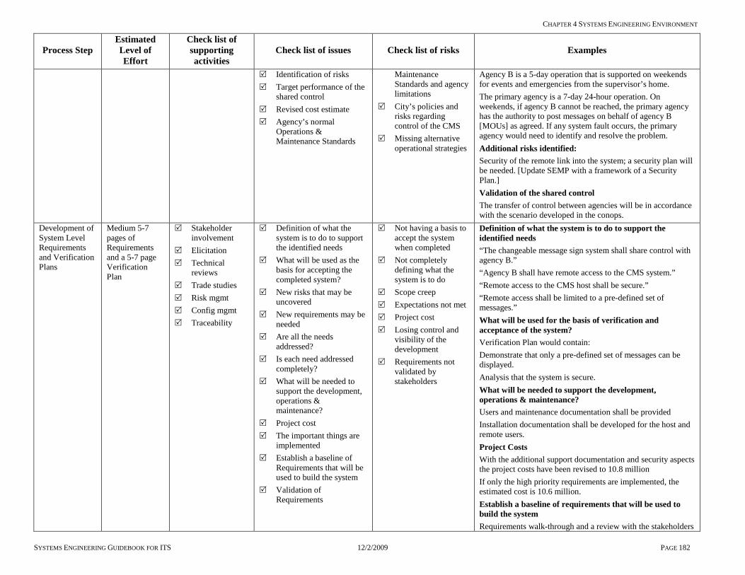
CHAPTER 4 SYSTEMS ENGINEERING ENVIRONMENT
SYSTEMS ENGINEERING GUIDEBOOK FOR ITS 12/2/2009 PAGE 182
Process Step Estimated Level of Effort
Check list of supporting activities
Check list of issues Check list of risks Examples
Identification of risks Target performance of the
shared control Revised cost estimate Agency’s normal
Operations & Maintenance Standards
Maintenance Standards and agency limitations
City’s policies and risks regarding control of the CMS
Missing alternative operational strategies
Agency B is a 5-day operation that is supported on weekends for events and emergencies from the supervisor’s home. The primary agency is a 7-day 24-hour operation. On weekends, if agency B cannot be reached, the primary agency has the authority to post messages on behalf of agency B [MOUs] as agreed. If any system fault occurs, the primary agency would need to identify and resolve the problem. Additional risks identified: Security of the remote link into the system; a security plan will be needed. [Update SEMP with a framework of a Security Plan.] Validation of the shared control The transfer of control between agencies will be in accordance with the scenario developed in the conops.
Development of System Level Requirements and Verification Plans
Medium 5-7 pages of Requirements and a 5-7 page Verification Plan
Stakeholder involvement
Elicitation Technical
reviews Trade studies Risk mgmt Config mgmt Traceability
Definition of what the system is to do to support the identified needs
What will be used as the basis for accepting the completed system?
New risks that may be uncovered
New requirements may be needed
Are all the needs addressed?
Is each need addressed completely?
What will be needed to support the development, operations & maintenance?
Project cost The important things are
implemented Establish a baseline of
Requirements that will be used to build the system
Validation of Requirements
Not having a basis to accept the system when completed
Not completely defining what the system is to do
Scope creep Expectations not met Project cost Losing control and
visibility of the development
Requirements not validated by stakeholders
Definition of what the system is to do to support the identified needs “The changeable message sign system shall share control with agency B.” “Agency B shall have remote access to the CMS system.” “Remote access to the CMS host shall be secure.” “Remote access shall be limited to a pre-defined set of messages.” What will be used for the basis of verification and acceptance of the system? Verification Plan would contain: Demonstrate that only a pre-defined set of messages can be displayed. Analysis that the system is secure. What will be needed to support the development, operations & maintenance? Users and maintenance documentation shall be provided Installation documentation shall be developed for the host and remote users. Project Costs With the additional support documentation and security aspects the project costs have been revised to 10.8 million If only the high priority requirements are implemented, the estimated cost is 10.6 million. Establish a baseline of requirements that will be used to build the system Requirements walk-through and a review with the stakeholders

CHAPTER 4 SYSTEMS ENGINEERING ENVIRONMENT
SYSTEMS ENGINEERING GUIDEBOOK FOR ITS 12/2/2009 PAGE 183
Process Step Estimated Level of Effort
Check list of supporting activities
Check list of issues Check list of risks Examples
is performed for acceptance of the requirements document to establish a system baseline
High Level Design Sub-system Requirements and Verification Plans
Medium 3-5 pages for each of the sub-systems
Stakeholder involvement
Trade studies Risk mgmt Config mgmt Technical
reviews Procurement
What Project Architectures will be viable
Sub-system Requirements Identification of candidate
commercial off the shelf products
Establish a sub-system baseline for each sub-system - performance
Establish interface standards
Sub-system verification Add content to the plans
as appropriate Selection of a systems
integrator Project costs and risks
Not deployable Not maintainable Inflexible Agency B staff
cannot access internet from home or remotely
Lack of Standards That the sub-systems
are not verified Project costs Lack of facilities and
services for new functionality
Decomposed incorrectly
What project architectures are viable: Centralized control with direct dial-in remote links Centralized control with access via internet Centralized control call in/email via operator [man in-the-loop] Distributed workstations direct to field controllers Recommended Architecture Centralized control with access via internet [Rational] Remote workstations are platform independent Flexible in a multi-agency environment Maintenance for remotes are minimized VPN technology offers fairly good security Remote software maintained at host [thin client] Project Costs Revised cost estimate based on responses from system integrator proposals
Development of Component Level Design
Defined by the SEMP – Development Plan
Stakeholder involvement
Trade studies Risk mgmt Config mgmt Technical
reviews Procurement
Provide content to SEMP Reverse engineer the
legacy system software and restructure for remote application [As-builds]
Recommendations from the system integrator on alternatives
Definition on how to implement the recommended architecture
Develop the software architecture for the system
Develop build-to specifications
Establish a detailed design baseline
Verification of the units Identification of
configuration items Critical design review
Lack of a specification to build the system
Are there alternatives that were missed?
Lack of a modular design
Lack of unit verification
Lack of documentation for legacy system to make the needed changes to the affected areas of the system
Not all requirements are addressed
Losing configuration control
Provide Content to SEMP Development Plan and schedules Configuration Management Plan Risk Plan Integration Plan Deployment Plan Security Plan Definition on how to implement the recommended architecture: Detailed design of software architecture Specify the internal interfaces between the central system software for new functionality Specify Java applets developed at the host for remote access Detailed design specifications [code-to] for the Java applets and user interface Specify VPN strategy Detailed design of Oracle application Specify an internet server using Apache technology and Oracle
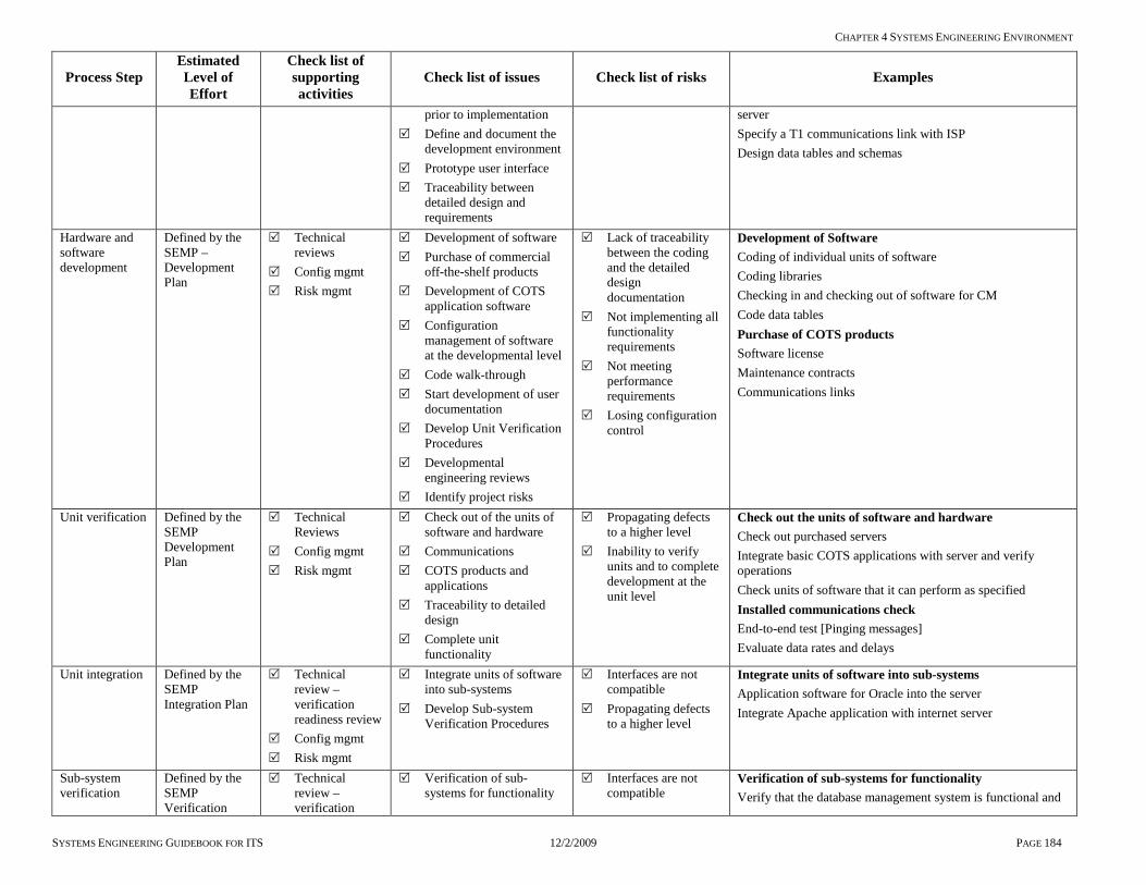
CHAPTER 4 SYSTEMS ENGINEERING ENVIRONMENT
SYSTEMS ENGINEERING GUIDEBOOK FOR ITS 12/2/2009 PAGE 184
Process Step Estimated Level of Effort
Check list of supporting activities
Check list of issues Check list of risks Examples
prior to implementation Define and document the
development environment Prototype user interface Traceability between
detailed design and requirements
server Specify a T1 communications link with ISP Design data tables and schemas
Hardware and software development
Defined by the SEMP – Development Plan
Technical reviews
Config mgmt Risk mgmt
Development of software Purchase of commercial
off-the-shelf products Development of COTS
application software Configuration
management of software at the developmental level
Code walk-through Start development of user
documentation Develop Unit Verification
Procedures Developmental
engineering reviews Identify project risks
Lack of traceability between the coding and the detailed design documentation
Not implementing all functionality requirements
Not meeting performance requirements
Losing configuration control
Development of Software Coding of individual units of software Coding libraries Checking in and checking out of software for CM Code data tables Purchase of COTS products Software license Maintenance contracts Communications links
Unit verification Defined by the SEMP Development Plan
Technical Reviews
Config mgmt Risk mgmt
Check out of the units of software and hardware
Communications COTS products and
applications Traceability to detailed
design Complete unit
functionality
Propagating defects to a higher level
Inability to verify units and to complete development at the unit level
Check out the units of software and hardware Check out purchased servers Integrate basic COTS applications with server and verify operations Check units of software that it can perform as specified Installed communications check End-to-end test [Pinging messages] Evaluate data rates and delays
Unit integration Defined by the SEMP Integration Plan
Technical review – verification readiness review
Config mgmt Risk mgmt
Integrate units of software into sub-systems
Develop Sub-system Verification Procedures
Interfaces are not compatible
Propagating defects to a higher level
Integrate units of software into sub-systems Application software for Oracle into the server Integrate Apache application with internet server
Sub-system verification
Defined by the SEMP Verification
Technical review – verification
Verification of sub-systems for functionality
Interfaces are not compatible
Verification of sub-systems for functionality Verify that the database management system is functional and

CHAPTER 4 SYSTEMS ENGINEERING ENVIRONMENT
SYSTEMS ENGINEERING GUIDEBOOK FOR ITS 12/2/2009 PAGE 185
Process Step Estimated Level of Effort
Check list of supporting activities
Check list of issues Check list of risks Examples
Master Plan and Verification Procedures
readiness review Config mgmt Risk mgmt
Make ready for the next level of integration
Update user documentation
Complete sub-system functionality
Sub-system functions not complete
Not meeting performance
Propagating defects to a higher level
that the data tables are populated and can be accessed within the performance requirements The Apache application is functional and accessibility of the server to the internet is functional
Sub-system integration
Defined by the SEMP Integration Plan
Technical review
Verification readiness review
Config mgmt Risk mgmt
Integrate sub-systems together into the final system configuration
Update user documentation
Update Operations & Maintenance Plans
Initial deployment and transition into Operations Plan update
System Verification Procedures
Operating agency staff not ready for operations & maintenance
Final configuration is not appropriate
Documentation for users is not ready
Propagating defects to a higher level
Integrate sub-systems into the final systems configuration Integrate the Apache server and internet communications with the Java applet exercise system, end-to-end check for memory leaks, fault conditions, browser compatibility, security, sign filtering [be able to access only the signs required for agency B]. Check Oracle database for agency profiles and login authority.
System verification
Defined by the SEMP Verification Plan
Stakeholder involvement
Technical reviews
Verification readiness reviews
Config/ Risk mgmt
Verify that the system meets all requirements
All documentation is updated and ready for users
Complete system functionality
System not fully implemented
System does not meet requirements
System does not meet the needs of the user
All documentation is updated and ready for users All user training, maintenance, user manuals are completed
Deployment Defined by the SEMP Deployment Plan
Technical review
Deployment readiness review
Determine if system is ready to be deployed
Evaluation period Training updates
System is not ready to be deployed
Latent defects that did not surface during verification
Determine if system is ready to be deployed Staff is trained, Internet access is available, VPN is configured, agency profiles are fully populated, access to the correct signs has been verified, remote users can read the 6 CMS status and post appropriate messages
Validation Defined by the SEMP Validation
Stakeholder involvement
Risk mgmt Config mgmt
Pre-system studies vs. post-system evaluation, effects on event management
Not meeting the expectations of the stakeholders
Not meeting the needs as specified in Concept of Operations
Pre-system studies vs. post-system evaluation, effects on event management In the pre-system evaluation it took 7 staff members 2 hours to set up the event management process. The effects on the event - it took 30 minutes from the end of the event to move traffic out of the area. It took 45 minutes prior to the event to park the event attendees. In the post-system evaluation it took 1 staff member 10 minutes to set up the event management process. The effectiveness of dynamically changing the signs shows when it

CHAPTER 4 SYSTEMS ENGINEERING ENVIRONMENT
SYSTEMS ENGINEERING GUIDEBOOK FOR ITS 12/2/2009 PAGE 186
Process Step Estimated Level of Effort
Check list of supporting activities
Check list of issues Check list of risks Examples
took only 15 minutes to clear the event and 30 minutes to park the event attendees.
Operations & maintenance
Defined by the Operations & Maintenance Plan
Stakeholder involvement
Config mgmt
On-going maintenance costs
On-call services contracts with COTS vendors
IT support for VPN and internet access
Lack of maintenance Lack of vendor
support
On-call services contracts with COTS vendors Updates to Oracle, notice of obsolescence, design changes
Changes & upgrades
Defined by the new project SEMP
Stakeholder involvement
Config mgmt
Other agencies want access to signs in their jurisdictions
Need for new development
Locked into a specific development team
Other agencies want access to signs in their jurisdictions Since the sharing control sub-system was designed for flexibility, it was found that no new development was needed, that adding new profiles and VPNs for the participating agencies would allow the system to accommodate new users without further design Since the new functionality was well documented, the agency has a choice of future development teams and additional functionality, if needed. Or, they can do it themselves.

CHAPTER 4 SYSTEMS ENGINEERING ENVIRONMENT
SYSTEMS ENGINEERING GUIDEBOOK FOR ITS 12/2/2009 PAGE 187
4.11.3 Example Project 3 - Implementing a New Central Management System [Please note that the solution given here is for this example only. Other viable solutions may be possible and each must be evaluated for a given project.] This project involves replacing an obsolete traffic signal management system with a new system. This system uses computers located at City Hall to provide remote monitoring and control of traffic signals. The existing system is no longer supported by the manufacturer. It is unreliable and not maintainable. It lacks the functionality needed and available in more modern systems. A needs & feasibility study identified needs, high-level requirements, investigated the capabilities, and costs of available off-the-shelf traffic signal management systems. It concluded that an off-the-shelf system using existing communications infrastructure will suffice. However, the existing signal controllers [not cabinets], central computers, and software will need to be replaced. The estimated project cost is $1,500,000, exclusive of on-going operation and maintenance costs. There is no immediate need for center-to-center interaction between this system and other systems. The stakeholders desire is to exchange data in the future. This is a relatively straight-forward project that requires a low to moderate level of systems engineering. The absence of new software development, use of COTS components, re-use of existing communications infrastructure, and absence of integration with other systems… all reduce risk and complexity. On the other hand, selection of the optimum system, ensuring the new system operates effectively, achieving a smooth transition from the old system to the new, ensuring operations & maintenance personnel are adequately trained, and having the project completed within budget and schedule will require careful project management [including appropriate systems engineering].
Process Step Estimated Level of Effort
Check list of supporting activities Check list of issues Check list of risks Examples
Feasibility Medium 2-5 pages
Products survey Identification of
alternative approaches
High-level trade study
Stakeholder involvement [personnel from management, operations, maintenance]
Risk management
Documentation and analysis of:
Needs to be addressed
Possible solution concepts
Estimated cost and benefit
Feasibility with off-the-shelf systems
Project risks Compatibility with
regional ITS architecture
Technical metrics and performance measures
Picking a point solution without considering the business case or cost benefit of alternatives.
Proposing a solution that is too costly
Incompatible components
Definition of the need: “Provide a traffic signal management system that is reliable, maintainable, and provides the needed functionality”. Source of quote Feasibility: Do available off-the-shelf products address the need? How much of the existing equipment and infrastructure will need to be replaced or upgraded? Is there an affordable solution? Trade study and cost benefit: Evaluate alternative approaches, such as retaining existing computers, controllers, cabinets, and communications infrastructure versus replacing some or all of these. Consider alternative communications protocols, their impact on initial and future product choices, communications infrastructure requirements, and options. Stakeholder issues: Consider performance measurement, needs of management, monitoring, control features needed by operations personnel, and self-diagnostic features needed by maintenance personnel. Risk management: Ask product vendors for input and cost estimates to

CHAPTER 4 SYSTEMS ENGINEERING ENVIRONMENT
SYSTEMS ENGINEERING GUIDEBOOK FOR ITS 12/2/2009 PAGE 188
Process Step Estimated Level of Effort
Check list of supporting activities Check list of issues Check list of risks Examples
ensure proposed solution is feasible and affordable Base analysis on mature, proven products Forego requirements that would require modification to off-the-shelf software or hardware Give preference to flexible, standards-based solutions
Planning Medium 3-5 pages Systems Engineering Management Plan
Describe the work tasks including project management
Identify project execution team, its organization, and the role of each member
Identify any consultant, system integrator, or vendor contracts needed
Document estimated cost and funding sources
Prepare a project time schedule
Identify needed Systems Engineering Plans and their outlines
Availability and expertise of in-house staff
Effort and time required to get consultants on board
Need for independent verification [acceptance testing]
Allowance for contingencies in budget and schedule
Project management techniques and tools to be used
Consider need for on-going maintenance contract with vendor
Loss of control of the project deliverable, schedule, and budget
Missing critical activities
Personnel changes
The identified systems engineering plans might include: Deployment Plan Verification and Validation Plans Project Plan Operations & Maintenance Plan Configuration Management Plan Risk Management Plan
Concept of Operations and Validation Plan
Low 1-2 pages Traffic signal management systems are well understood and do not need an elaborate concept of operations or Validation Plan
Elicitation Stakeholder
involvement Risk management Trade studies Technical reviews
Description of the way the system will operate and be maintained
Identification of the project level stakeholders e.g.
Maintenance Operators Managers IT department Definition of user
needs at the project level
Agency’s normal operations &
Lack of understanding on:
How the system will be operated or maintained
Scope of the project What functionality is
available in off-the-shelf products
How the system will operate: Central software will continuously monitor the operation of traffic signals, reporting current status, traffic flow data, and alarms. The system automatically synchronizes the clocks in signal controllers and commands controllers to change timing patterns when appropriate. Operators periodically check status, update signal timings, respond to alarms, use collected data in various analyses, add new signals to the system, and use the system to temporarily adjust signal timings during incidents. Measures of effectiveness for validation: Traffic signal equipment failures are reliably detected and appropriate personnel notified in a timely manner Data collected by the system are successfully used for
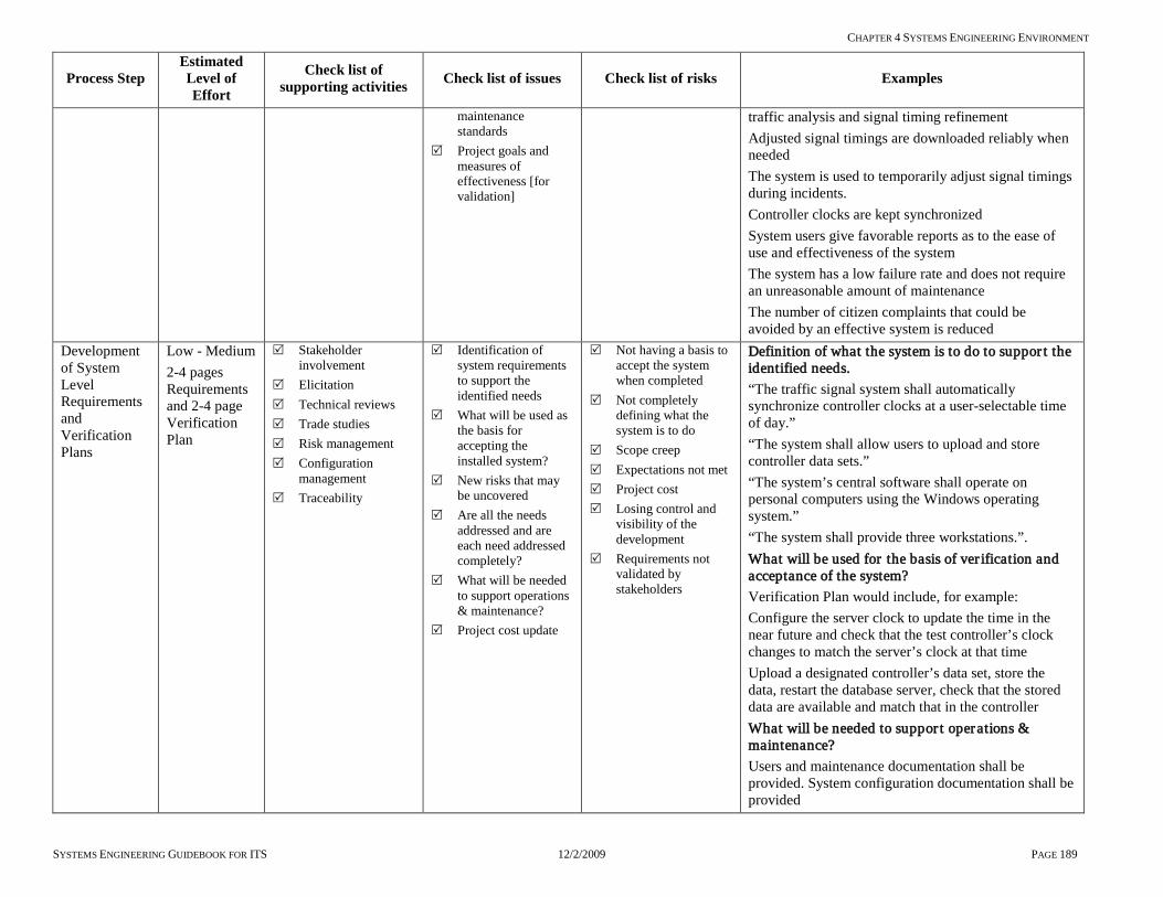
CHAPTER 4 SYSTEMS ENGINEERING ENVIRONMENT
SYSTEMS ENGINEERING GUIDEBOOK FOR ITS 12/2/2009 PAGE 189
Process Step Estimated Level of Effort
Check list of supporting activities Check list of issues Check list of risks Examples
maintenance standards
Project goals and measures of effectiveness [for validation]
traffic analysis and signal timing refinement Adjusted signal timings are downloaded reliably when needed The system is used to temporarily adjust signal timings during incidents. Controller clocks are kept synchronized System users give favorable reports as to the ease of use and effectiveness of the system The system has a low failure rate and does not require an unreasonable amount of maintenance The number of citizen complaints that could be avoided by an effective system is reduced
Development of System Level Requirements and Verification Plans
Low - Medium 2-4 pages Requirements and 2-4 page Verification Plan
Stakeholder involvement
Elicitation Technical reviews Trade studies Risk management Configuration
management Traceability
Identification of system requirements to support the identified needs
What will be used as the basis for accepting the installed system?
New risks that may be uncovered
Are all the needs addressed and are each need addressed completely?
What will be needed to support operations & maintenance?
Project cost update
Not having a basis to accept the system when completed
Not completely defining what the system is to do
Scope creep Expectations not met Project cost Losing control and
visibility of the development
Requirements not validated by stakeholders
Definition of what the system is to do to suppor t the identified needs. “The traffic signal system shall automatically synchronize controller clocks at a user-selectable time of day.” “The system shall allow users to upload and store controller data sets.” “The system’s central software shall operate on personal computers using the Windows operating system.” “The system shall provide three workstations.”. What will be used for the basis of ver ification and acceptance of the system? Verification Plan would include, for example: Configure the server clock to update the time in the near future and check that the test controller’s clock changes to match the server’s clock at that time Upload a designated controller’s data set, store the data, restart the database server, check that the stored data are available and match that in the controller What will be needed to suppor t operations & maintenance? Users and maintenance documentation shall be provided. System configuration documentation shall be provided

CHAPTER 4 SYSTEMS ENGINEERING ENVIRONMENT
SYSTEMS ENGINEERING GUIDEBOOK FOR ITS 12/2/2009 PAGE 190
Process Step Estimated Level of Effort
Check list of supporting activities Check list of issues Check list of risks Examples
System design
Low - medium 5-8 pages Design Document including map and diagrams
Stakeholder involvement,
Trade studies Risk management Configuration
management Technical reviews Procurement
Evaluate alternative off-the-shelf systems by comparing against requirements and considering costs
Procure the preferred system
Work with supplier to prepare system design
Project costs and risks
Refine Verification Plan
Not deployable Not maintainable Inflexible Lack of standards Project costs
Examples of design elements: Including any cabinet wiring changes, controller options, communication protocol choice, computer furniture, graphics style. Map showing location of signals to be integrated in the new system and communication infrastructure used. Any cabinet wiring modifications Controller firmware version to be installed Process for converting and transferring existing controller data sets to the new controllers Any new racks and furniture needed at central Configuration of computers Graphics style and source of base drawings Naming conventions Definition of signal groupings Cutover Plan Training Plan Project costs Revised cost estimate based on final system design
Development of Component Level Design
No detailed component-level design needed since all system components are off-the-shelf.
Hardware and software development
Not needed, since all components are off-the-shelf

CHAPTER 4 SYSTEMS ENGINEERING ENVIRONMENT
SYSTEMS ENGINEERING GUIDEBOOK FOR ITS 12/2/2009 PAGE 191
Process Step Estimated Level of Effort
Check list of supporting activities Check list of issues Check list of risks Examples
Unit verification
Defined by the Deployment Plan and Verification Plan
Technical reviews Configuration
management Risk management
Inspect and test the units of software and hardware
Traceability to detailed design
Complete unit functionality
Propagating defects to a higher level
Inability to verify units
Inspect and test the units of software and hardware Computers and installed software – before any signals are connected Controllers and installed firmware – stand alone bench tests
Unit integration
Defined by the Deployment Plan
Technical review – verification readiness review
Configuration management
Risk management
Integrate units of software into sub-systems
Develop sub-system verification procedures
Interfaces are not compatible
Propagating defects to a higher level
Integrate components into sub-systems Prepare and install a test controller in a bench cabinet. Connect the bench controller in a cabinet to the communications server Install software and data sets in all controllers, ready for installation
Sub-system verification
Defined by the Verification Plan and Verification Procedures
Technical review – verification readiness review
Configuration management
Risk management
Verification of sub-systems for functionality
Make ready for the next level of integration
Update user documentation
Interfaces are not compatible
Sub-system functions not complete
Not meeting performance
Propagating defects to a higher level
Ver ification of sub-systems for functionality Verify that the central software can successfully communicate with a test controller on the bench Test system functionality with the bench controller connected
Sub-system integration
Defined by the Deployment Plan
Technical review Verification
readiness review Configuration
management Risk management
Integrate sub-systems together into the final system configuration
Update user documentation
Update Operations & Maintenance Plans
Initial deployment and transition into Operations Plan update
System verification procedures
Operating agency staff not ready for operations & maintenance
Final configuration is not appropriate
Documentation for users is not ready
Propagating defects to a higher level
Integrate sub-systems into the final system’s configuration Make any needed modifications to cabinets in the field. Install new controllers in the field. Complete installation of computers and other central equipment. Connect field controllers to the central communications server. Complete central software configuration
System verification
Defined by the Verification Plan
Stakeholder involvement
Technical reviews Verification
Verify that the system meets all requirements
All documentation is
System not fully implemented
System does not meet requirements
System passes all acceptance tests. Perform system-level acceptance tests in accordance with the Verification Plan

CHAPTER 4 SYSTEMS ENGINEERING ENVIRONMENT
SYSTEMS ENGINEERING GUIDEBOOK FOR ITS 12/2/2009 PAGE 192
Process Step Estimated Level of Effort
Check list of supporting activities Check list of issues Check list of risks Examples
readiness reviews Configuration
management Risk management
updated and ready for users
Complete system functionality
System does not meet the needs of the user
All documentation is updated and ready for users All user training, maintenance, and user manuals are completed. The system configuration is fully documented
Deployment Since this is a replacement system, deployment has already occurred by this stage.
New system cannot be co-installed with old system
New system cutover has the ability to fall back to the old legacy system if problems occur
Validation Defined by SEMP Validation Plan
Stakeholder involvement
Evaluate system effectiveness
Not meeting the expectations of the stakeholders
Not meeting the needs as specified in Concept of Operations
System evaluation Does the system provide the benefits expected? Are users able to use it effectively? Are field equipment faults reported reliably and quickly? Is it reliable and easy to maintain?
Operations & Maintenance
Defined by the Operations & Maintenance Plan
Stakeholder involvement
Configuration management
On-going maintenance costs
On-call service contracts with vendors
IT support for servers and remote access
Lack of maintenance Lack of vendor
support
On-going operation and maintenance. Ensure operations staff are available and using the system as needed Arrange vendor support contracts if needed, after warranty period Provide operation & maintenance training for new employees Maintain spare parts inventory Keep system configuration documentation up to date Track system shortcomings and additional needs Plan changes & upgrades when needed.
Changes & upgrades
Defined by the new project SEMP
Stakeholder involvement
Configuration management
System not performing needed functions
System becoming difficult to maintain.
Need for new software development
Locked into a specific vendor
Examples of reasons to change or upgrade Equipment or software may become obsolete May need to add a center-to-center connection May need to add cameras or signs

CHAPTER 5 CASE STUDIES KEY LESSONS
SYSTEMS ENGINEERING GUIDEBOOK FOR ITS 12/2/2009 PAGE 193
5 CASE Studies Key Lessons Objective: To examine real world project and provide key lessons learn when applying systems engineering process to Transportation and transit projects. This Chapter examines the following three (3) case studies. 1] New York City Transit The project provides Automatic Train Supervision (ATS) for the A Division of the New York City subway system Acknowledgements: Ms Anne O’Neil MTA’s New York City Transit – Chief Commissioning Officer for Systems and Ms Deborah Chin MTA’s New York City Transit – Deputy Commissioning Officer for Systems generously contributed this case study for the SE Guidebook. 2] Baltimore ATMS project The City of Baltimore Integrated Traffic Management System is a major upgrade of the City of Baltimore’s street traffic management system. Acknowledges: Ziad Sabra, Principal of Sabra, Wang & Associates, generously contributed his time for interviews, and contributed much of the information collected for this case study 3] Maryland Chart projects CHART (Coordinated Highways Action Response Team) is an incident management system for roadways in Maryland. Acknowledgement: Richard Dye, CHART Systems Administrator, generously contributed his time for interviews,
and contributed much of the information collected for this case study. These case studies represent a range of transportation and transit projects that involve the use of the systems engineering process and lessons learned. The New York Transit project represents the systems engineering process used, lessons learned, and what would be done differently on the next project. The case study also represents a large transit property. The Baltimore ATMS project represent a typical centralized signal systems project. This represents a vast majority of projects that transportation practitioners would encounter. This project examines the lessons learned in the area of procurement, experience, testing, and implementation. Finally the Maryland Chart project examines the lessons learned on a major statewide ITS project. This project used a fairly rigorous systems engineering process and a significant amount of documentation produced. There was a short falls in the capabilities needed on this project. This chapter contains the summary of each case study. Chapter 8.5 contains the complete case study as developed by the sponsor of the project.

CHAPTER 5.1 CASE STUDY 1 KEY LESSONS LEARNED – MTA NEW YORK CITY TRANSIT ATS
SYSTEMS ENGINEERING GUIDEBOOK FOR ITS 12/2/2009 PAGE 194
5.1 Case Study 1 Key lessons learned – MTA New York City Transit ATS System Description The project provides Automatic Train Supervision (ATS) for the A Division of the New York City subway system. It automates many of the real-time train control functions now performed manually, while generating train location and
performance data for travelers and operators. It also allows a single control center to replace several regional manual control towers. The project is nearing completion as this report is written in the summer of 2006.
The Key Lessons Learned from the NYC Automatic Train Supervision Project
Issues Encountered Lessons learned
Future users did not have a clear understanding of screen interactions when only evaluating individual presentation screens. Workstation workspace was purposely planned to be tailor-able to an individual’s preferences therefore a “typical” screen layout could not evaluated for usability.
Prototyping should be demonstrated on an actual workstation mock-up.
Prototype agreements were embedded in “discussions”. The contractor tracked them to the design documents that lacked the appropriate detail to address these issues. Much effort was spent by NYCT to make sure that agreements were not bypassed during acceptance test.
Prototype agreements should clearly be identified following the criteria for requirements: unambiguous, unique, and testable. They should be tracked as supplemental contract requirements.
The independent test team slowly disintegrated. Only developers remained. In addition to the conflict of issues problem is: Developers seldom know more than their own area well; not the whole system. Developers also typically feel testing is not part of their job. Time spent by developers testing impacts project schedule because variances are not being corrected.
Independent Contractor Test Team – Confirm adequate coverage in specification to assure this standard development process protocol.
As implementation and testing progresses, the design documents are further and further from reality. Other SOWs, letters of direction, memos and e-mails constitute the actual design. Every change such as this should include an equivalent documentation update; the release letter should identify which documents are affected.
Design Document updates – When design is altered or more detail is added due to prototype, variances, AWOs etc. A new release is not expected, however the working copy of the design document should be modified and available on-line .
No time was saved by accepting virtual milestones; rather time was lost in later phases of the project for longer durations.
Design Review milestones should be taken seriously and successful completion should be a prerequisite for proceeding to the next review phase.
Inappropriate skills and competencies of personnel resulted in the wrong individuals inspecting, testing, and accepting equipment/systems; Construction Manager was forced to make decisions without the right technical support.
An NYCT Integrated Project Team should be formed and dedicated to support the Construction Manager.
The requirements were never truly “base-lined”, which posed difficulty to the project team to assess necessary changes. Without a formal change process through a Change Control Board many decisions were made by management without careful evaluation of the impacts to the entire system, and the associated risks to the project.
Change Control Board – Should be instituted early in the process and include NYCT involvement.
Traceability of system performance requirements is time consuming and has yet to be completed.
Requirements Traceability Tool should be utilized from a “systems” perspective.
Although working groups were established, discipline engineers still had a tendency to work with a stove-piped approach to design and implementation of their specific sub-systems.
Need to have a Systems Engineering Management Plan to define roles & responsibilities of the project team.
Mismatch of qualified testers during critical phases of site-acceptance testing; Delays to project schedule also resulted in operations staff having to be re-trained.
Operator training needs to be conducted early enough in the project to provide available and qualified resources to support testing activities.

CHAPTER 5.2 CASE STUDY 2 KEY LESSONS LEARNED – BALTIMORE TRAFFIC MANAGEMENT
SYSTEMS ENGINEERING GUIDEBOOK FOR ITS 12/2/2009 PAGE 195
5.2 Case Study 2 Key lessons learned – Baltimore Traffic Management System Description The City of Baltimore Integrated Traffic Management System is a major upgrade of the City of Baltimore’s street traffic management system. It involved replacement of all traffic signal controllers and cabinets, installation of additional closed circuit television cameras, upgrading and expansion of center-to-field communications infrastructure, video exchange with CHART, a new traffic management center, new central computer hardware and software for remote management of field devices, and updated traffic signal timings. The Key Lessons Learned from the Baltimore Integrated TMS Project Use of an experienced program manager and the systems engineering process enabled a complex project to be successful. Flexible contracts with the program manager and system integrator enabled the contracts to be changed midstream to accommodate unforeseen or changed conditions. Use of the NTCIP communications standard was key to enabling integration of central software and field equipment from different manufacturers, and in giving the City the option to purchase future field equipment from different manufacturers.
Thorough and realistic testing at every stage of system implementation, involving the owning agency in testing, and testing every change no matter how small and seemingly inconsequential, helps with progress monitoring and avoids expensive and time consuming field retrofits. Contractor submittals should include a signatures page that all concerned personnel must sign before work can proceed. This ensures the document has been reviewed and approved by all interested parties. Use of old equipment can lead to unforeseen problems that need to be accommodated. Facilities that work fine with an existing system may not be adequate for the new system with its different characteristics. Contracts should clearly delineate boundaries of responsibilities between the involved parties. Adequate training of all involved personnel is important, especially when new technology is being used or existing technology is being used in a new way. A carefully planned and methodical cut-over plan can add to the efficiency of changing over from old to new equipment.

CHAPTER 1.1
SYSTEMS ENGINEERING GUIDEBOOK FOR ITS 12/2/2009 PAGE 196
5.3 Case Study 3 Key lessons learned – Maryland Char t project
System Description CHART (Coordinated Highways Action Response Team) is an incident management system for roadways in Maryland. It is a joint effort of the Maryland Department of Transportation, Maryland Transportation Authority (toll authority), and the Maryland State Police in cooperation with other federal, state, and local agencies. The system described here is actually the second version of the original CHART system, and is technically called CHART II. The CHART system was successfully deployed and has achieved its goals. Annual evaluations performed by the University of Maryland have documented the considerable benefits of CHART, which far exceed its cost. The Key Lessons Learned in the Application of Systems Engineering to CHART The rigorous systems engineering process took time and money, but paid off in the successful operation of the system and the ability to maintain and enhance it. High Agency involvement in the definition of the system was important to the system development. Well documented software allowed other system integrators to upgrade the system. A time-and-materials, task-order agreement with the primary contractor allowed the system to
evolve over multiple incremental versions rather than a single deliverable as originally envisioned. This allowed more rapid implementation of the base system, and subsequent feedback from users lead to a better final product. Despite the thorough software documentation, on-going software maintenance and enhancement upgrades have been found to be very time consuming. Software maintenance activities have therefore been divided into three categories – routine maintenance (e.g., upgrade operating system), minor functional changes and fixes, and major functional enhancements. Better software cost estimation skills by the agency are desired and the agency is pursuing Project Management Institute (PMI) certification for all major IT project managers. Using a qualified independent verification consultant was a contractual requirement of the agency and is felt to have been critical to the success CHART has achieved to date. The contract required that the software contractor have a solid history of using systems engineering and also required that the winning contractor to bring its documented internal systems engineering processes to the project and train the agency in its use.

CHAPTER 6 ROLES AND RESPONSIBILITIES IN SYSTEMS DEVELOPMENT
SYSTEMS ENGINEERING GUIDEBOOK FOR ITS 12/2/2009 PAGE 197
6 Roles and Responsibilities in Systems Development OBJECTIVE: This section describes the various roles to be performed in the development life cycle of an ITS project. It provides guidance on “what the roles entail” and “who the potential candidates are to perform them”. A matrix shows what role is played by the system’s owner, the systems engineering technical assistant, and the development team during each stage of the development life cycle. The role of the system’s owner, systems engineering technical assistant, and development team will vary in level of involvement and areas of responsibility throughout the project life cycle. This chapter provides guidance in each development step. It identifies the roles needed in each phase of the life cycle of an ITS project. A matrix of roles and responsibilities follows this discussion. System’s Owner [Project Sponsor & Stakeholders] The system’s owner [project sponsor & stakeholders] implementing an ITS will acquire a set of development services to develop the ITS project. The services can be either in-house or contracted. The system’s owner and operating organization will ultimately be responsible for the system and its operations & maintenance. The system’s owner needs to supply clear requirements and expected project outcomes to the development team. These outputs must be compatible with the long-term operations & maintenance goals of the system’s owner & stakeholders. The success of the project relies on the system’s owner’s working relationship with the systems engineering technical assistant and development team[s] who implement the system. This chapter will identify the roles and responsibilities of the system’s owner at each phase of the ITS life cycle [from the interface to the regional ITS architecture to retirement & replacement of the system or major system elements]. Systems Engineering Assistant [In-house staff, Independent Verification and Validation, System Manager] The systems engineering assistant provides the system’s owner with specialty support in systems engineering. This role can be undertaken by in-house staff, a system manager, or an Independent Verification and Validation consultant [IV&V] to a limited extent. Contract resources are particularly valuable for large, complex, or unusual projects. It is also valuable when the system’s owner’s organization is small and lacks systems engineering expertise. This may be the
case with a small or medium size city or MPO. The systems engineering assistant: defines requirements and the project
architecture: prepares the request for proposal or other
system procurement documents, assists in the review of proposals, provides independent review services
[Independent Verification & Validation] Provides technical assistance to the system’s
owner during the life cycle of the ITS system. A consultant who neither offers products nor is affiliated with a development team or vendor can be un-biased in the selection and evaluation of developers and products. The consultant can assist the agency in Configuration Management, Risk Management, development team evaluations, and process improvement. It is important to find a consultant who has both systems engineering expertise and ITS knowledge and experience.
Development Team [In-house, Systems Integrator] An ITS system development team normally develops or supplies hardware and software that integrate custom [project-specific] and COTS products. The system’s owner secures the the following services of a development team: perform the detailed design develop any necessary custom hardware or
software integrate COTS products Verify the sub-systems and the system as a
whole The development team may be another department within the system owner’s organization [internal development team]. It may be a contracted integration team. This is the normal case for most organizations. The following tables identify the different roles and responsibilities during each phase of the project life-cycle.

CHAPTER 6 ROLES AND RESPONSIBILITIES IN SYSTEMS DEVELOPMENT
SYSTEMS ENGINEERING GUIDEBOOK FOR ITS 12/2/2009 PAGE 198
Table 6-1 Phases [-1] & 0 Roles and Responsibilities
Phase Phase [-1]
Interfacing to the Regional ITS Architecture
Phase 0 Concept Exploration and Feasibility Analysis
Tasks 3.2.1 Interfacing with Planning and the Regional ITS Architecture 3.3.1 Needs Assessment 3.3.2 Concept Exploration
and Benefits Analysis
Syst
em O
wne
r Pr
ojec
t Spo
nsor
&
Stak
ehol
ders
Coordinate, identify, participate: Coordinate with Planning Identify applicable portion of the
Regional Architecture Ensure that project goals &
objectives are sufficiently clear to support tasks
Review & approve: Statement of work Current inventories Supporting
documentation Identify & encourage
Stakeholder participation Actively participate in the
elicitation of Needs
Review & approve: Refined needs, vision,
goals, objectives, and constraints
Overall measures of performance
Candidate concepts Recommendations
Syst
ems E
ngin
eeri
ng
Tech
nica
l Ass
istan
ce
In-h
ouse
, Ind
epen
dent
Ver
ifica
tion
&
Val
idat
ion*
* C
onsu
ltant
, sys
tem
s Man
ager
Identify & document: Applicable portion of the RA Inventory Stakeholders Needs/Services RA Requirements Area of Coverage Operational Concept RA Interfaces RA Information flows ITS Standards Project Sequencing Agency agreements Constraints Goals & objective
Identify & document: Validated & prioritized
needs Challenges & issues Perform Gap Analysis Refine & update
stakeholder lists
Identify, refine & document: Vision, goals &
objectives Constraints Alternatives,
recommendations, and rationale
Develop: Evaluation criteria Measures of
performance Concepts Perform: Cost/benefit analysis Alternatives analysis
Dev
elop
men
t Te
am
In-h
ouse
, Sys
tem
In
tegr
ator
Review & comment* *subject to public comment e.g. Industry review of architecture
Review and comment* *subject to public comment e.g. Industry review of needs
Review & comment* *subject to public comment e.g. Vision, goals & objectives
** Independent Verification & Validation - role and responsibility are monitoring, reporting, supporting, and participating but not performing- applies to all phases and tasks
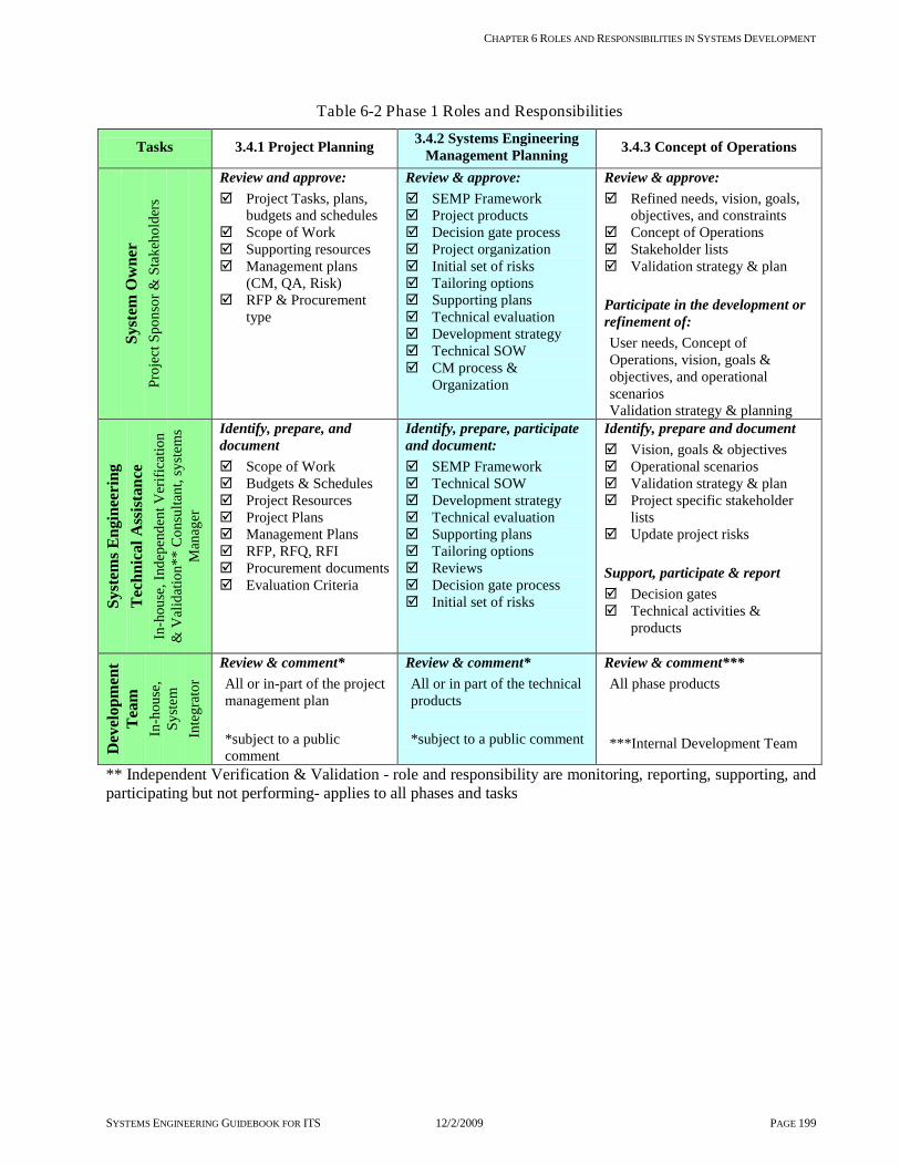
CHAPTER 6 ROLES AND RESPONSIBILITIES IN SYSTEMS DEVELOPMENT
SYSTEMS ENGINEERING GUIDEBOOK FOR ITS 12/2/2009 PAGE 199
Table 6-2 Phase 1 Roles and Responsibilities
Tasks 3.4.1 Project Planning 3.4.2 Systems Engineering Management Planning 3.4.3 Concept of Operations
Syst
em O
wne
r Pr
ojec
t Spo
nsor
& S
take
hold
ers
Review and approve: Project Tasks, plans,
budgets and schedules Scope of Work Supporting resources Management plans
(CM, QA, Risk) RFP & Procurement
type
Review & approve: SEMP Framework Project products Decision gate process Project organization Initial set of risks Tailoring options Supporting plans Technical evaluation Development strategy Technical SOW CM process &
Organization
Review & approve: Refined needs, vision, goals,
objectives, and constraints Concept of Operations Stakeholder lists Validation strategy & plan Participate in the development or refinement of: User needs, Concept of Operations, vision, goals & objectives, and operational scenarios Validation strategy & planning
Syst
ems E
ngin
eeri
ng
Tech
nica
l Ass
istan
ce
In-h
ouse
, Ind
epen
dent
Ver
ifica
tion
& V
alid
atio
n**
Con
sulta
nt, s
yste
ms
Man
ager
Identify, prepare, and document Scope of Work Budgets & Schedules Project Resources Project Plans Management Plans RFP, RFQ, RFI Procurement documents Evaluation Criteria
Identify, prepare, participate and document: SEMP Framework Technical SOW Development strategy Technical evaluation Supporting plans Tailoring options Reviews Decision gate process Initial set of risks
Identify, prepare and document Vision, goals & objectives Operational scenarios Validation strategy & plan Project specific stakeholder
lists Update project risks Support, participate & report Decision gates Technical activities &
products
Dev
elop
men
t Te
am
In-h
ouse
, Sy
stem
In
tegr
ator
Review & comment* All or in-part of the project management plan
*subject to a public comment
Review & comment* All or in part of the technical products
*subject to a public comment
Review & comment*** All phase products
***Internal Development Team
** Independent Verification & Validation - role and responsibility are monitoring, reporting, supporting, and participating but not performing- applies to all phases and tasks

CHAPTER 6 ROLES AND RESPONSIBILITIES IN SYSTEMS DEVELOPMENT
SYSTEMS ENGINEERING GUIDEBOOK FOR ITS 12/2/2009 PAGE 200
Table 6-3 Phase 2 Roles and Responsibilities
Tasks 3.5.1 Requirements Development 3.5.2 High Level Design 3.5.3 Component Level
Detailed Design Sy
stem
Ow
ner
Proj
ect S
pons
or &
Sta
keho
lder
s
Participate and facilitate: Stakeholder
participation Elicitation process for
requirements capture Monitor, review, and approve: Requirements baseline Requirements metrics
and tracking Project risks
Participate and facilitate: Stakeholder
participation Review & approve: Interface agreements Project architecture Monitor: Requirements baseline Project risks
Participate and facilitate: Stakeholder participation Technical reviews COTS product review Review & approve: Detailed design Contract for Development
Team Monitor Baseline requirements and
design Project risks
Syst
ems E
ngin
eeri
ng
Tech
nica
l Ass
istan
ce
In-h
ouse
, Ind
epen
dent
Ver
ifica
tion
& V
alid
atio
n**
Con
sulta
nt, s
yste
ms
Man
ager
Identify, Prepare, and document or update: Validated set of system
level requirements Requirements review Verification plan Interfaces Risks and trend Perform: Elicitation Analysis Decomposition Requirements baseline Completeness of
requirements Perform/Support: Feasibility analysis Support, participate and report Decision gates
Identify, prepare, and document (update) System Development
RFP Validated set of sub-
system requirements Project architecture
alternatives Interfaces Verification plans Integration plan Project risks Configuration items Perform: Elicitation Analysis Decomposition Requirements baseline Completeness of
requirements Perform/Support Feasibility analysis Support, participate and report Decision gates
Support, participate, review, and comment: Development team
evaluation COTS evaluation Detailed design Technical reviews Developmental CM Development risks Unit test procedures Technical plans:
- Integration - Deployment - Installation - Technology - Security - Development - O&M
Support, participate, and report Decision gates
Dev
elop
men
t Tea
m
In-h
ouse
, Sys
tem
In
tegr
ator
Review & comment* All or in-part all project
management plans *subject to availability to public comment
Review and comment* All or in-part all
Definition & Architecture
*subject to availability to public comment
Identify, prepare, and document: Technical plans Developmental plan Developmental CM Developmental risks Perform and document Detailed design Technical review
** Independent Verification & Validation - role and responsibility are monitoring, reporting, supporting, and participating but not performing- applies to all phases and tasks
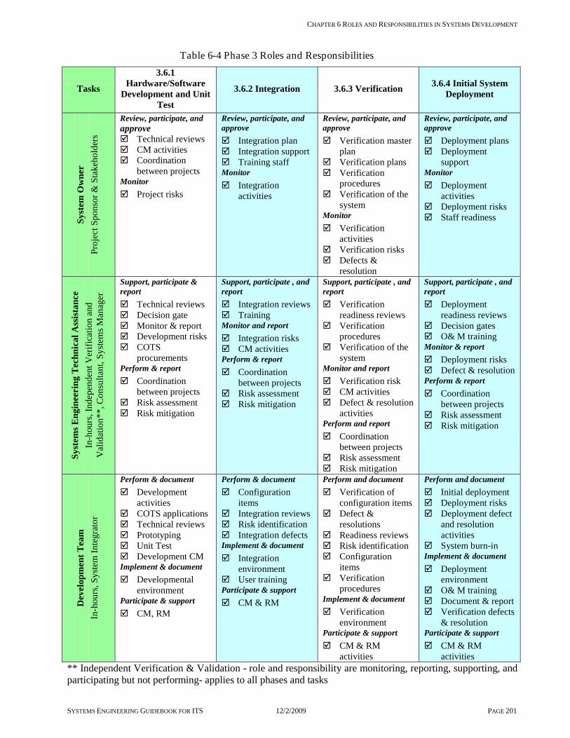
CHAPTER 6 ROLES AND RESPONSIBILITIES IN SYSTEMS DEVELOPMENT
SYSTEMS ENGINEERING GUIDEBOOK FOR ITS 12/2/2009 PAGE 201
Table 6-4 Phase 3 Roles and Responsibilities
Tasks
3.6.1 Hardware/Software
Development and Unit Test
3.6.2 Integration 3.6.3 Verification 3.6.4 Initial System Deployment
Syst
em O
wne
r Pr
ojec
t Spo
nsor
& S
take
hold
ers
Review, participate, and approve Technical reviews CM activities Coordination
between projects Monitor Project risks
Review, participate, and approve Integration plan Integration support Training staff Monitor Integration
activities
Review, participate, and approve Verification master
plan Verification plans Verification
procedures Verification of the
system Monitor Verification
activities Verification risks Defects &
resolution
Review, participate, and approve Deployment plans Deployment
support Monitor Deployment
activities Deployment risks Staff readiness
Syst
ems E
ngin
eeri
ng T
echn
ical
Ass
istan
ce
In-h
ours
, Ind
epen
dent
Ver
ifica
tion
and
Val
idat
ion*
*, C
onsu
ltant
, Sys
tem
s Man
ager
Support, participate & report Technical reviews Decision gate Monitor & report Development risks COTS
procurements Perform & report Coordination
between projects Risk assessment Risk mitigation
Support, participate , and report Integration reviews Training Monitor and report Integration risks CM activities Perform & report Coordination
between projects Risk assessment Risk mitigation
Support, participate , and report Verification
readiness reviews Verification
procedures Verification of the
system Monitor and report Verification risk CM activities Defect & resolution
activities Perform and report Coordination
between projects Risk assessment Risk mitigation
Support, participate , and report Deployment
readiness reviews Decision gates O& M training Monitor & report Deployment risks Defect & resolution Perform & report Coordination
between projects Risk assessment Risk mitigation
Dev
elop
men
t Tea
m
In-h
ours
, Sys
tem
Inte
grat
or
Perform & document Development
activities COTS applications Technical reviews Prototyping Unit Test Development CM Implement & document Developmental
environment Participate & support CM, RM
Perform & document Configuration
items Integration reviews Risk identification Integration defects Implement & document Integration
environment User training Participate & support CM & RM
Perform and document Verification of
configuration items Defect &
resolutions Readiness reviews Risk identification Configuration
items Verification
procedures Implement & document Verification
environment Participate & support CM & RM
activities
Perform and document Initial deployment Deployment risks Deployment defect
and resolution activities
System burn-in Implement & document Deployment
environment O& M training Document & report Verification defects
& resolution Participate & support CM & RM
activities ** Independent Verification & Validation - role and responsibility are monitoring, reporting, supporting, and participating but not performing- applies to all phases and tasks

CHAPTER 6 ROLES AND RESPONSIBILITIES IN SYSTEMS DEVELOPMENT
SYSTEMS ENGINEERING GUIDEBOOK FOR ITS 12/2/2009 PAGE 202
Table 6-5 Phase 4 & 5 Roles and Responsibilities
Phase Phase 4
Operation & Maintenance/Changes & Upgrades Phase 5
Retirement / Replacement
Tasks 3.7.1 System Validation
3.7.2 Operations and Maintenance
3.7.3 Changes and Upgrades
3.8.1 System Retirement / Replacement
Syst
em O
wne
r Pr
ojec
t Spo
nsor
& S
take
hold
ers
Review, participate, and approve Validation plans Validation
support Validation
procedures Validation of
the system Monitor Project risks Defects &
resolution
Review, participate, and approve Commission
system into operations
Updates to O&M plan
Monitor O&M
performance Life cycle CM
activities
Review, participate, and facilitate. Stakeholder
elicitation and participation
Perform tasks as defined in 3.4.1-3.6.2
Review, participate, and approve Reverse
engineering activities
Monitor Risks
Review, participate, and facilitate. Stakeholder
elicitation and participation
Industry review Perform tasks as
defined in 3.4.1-3.6.3 Review, participate, and approve Replacement plan Transition plan Monitor Risks
Syst
ems E
ngin
eeri
ng T
echn
ical
A
ssis
tanc
e In
-hou
rs, I
ndep
ende
nt V
erifi
catio
n an
d V
alid
atio
n**,
Con
sulta
nt, S
yste
ms
Man
ager
Perform & document Validation plan
& updates Pre-system
evaluation Post-system
evaluation Systems
analysis Strengths &
weaknesses Requirements
for next evolution
Support, participate , and report Operational
assessment Maintenance
assessment Life cycle CM
activities
Support, participate , and report Change review &
assessment CM activities Technology
demonstrations Perform and report Reverse
engineering activities
Tasks as defined in 3.4.1-3.6.2
Support, participate , and report Replacement
assessment Gap Analysis Evaluation of
benefits Technology
demonstrations Perform tasks as
defined in 3.4.1-3.6.3 Develop & Document Replacement strategy Transition plans
Dev
elop
men
t Tea
m
In-h
ours
, Sys
tem
In
tegr
ator
Participate & support Validation of
the system Validation
planning
Perform, support, and document Initial O&M
maintenance on-call service activities
Long term O & M
Perform, support, and document Changes as
defined in 3.4.1-3.6.2
Technology demonstrations
Perform, support, participate Perform tasks as
define in 3.4.1-3.6.3 Industry response to
potential solutions Technology
demonstrations Replacement of
legacy systems ** Independent Verification & Validation - role and responsibility are monitoring, reporting, supporting, and participating but not performing- applies to all phases and tasks

CHAPTER 7 SYSTEMS ENGINEERING CAPABILITIES AND PROCESS IMPROVEMENT
SYSTEMS ENGINEERING GUIDEBOOK FOR ITS 12/2/2009 PAGE 203
7 Systems Engineer ing Capabilities and Process Improvement 7.1 Why Process Improvement? Many problems that are encountered during ITS project development –budget overruns, schedule slips, excessive change orders, and disappointed stakeholders – are a direct result of the process that is used to develop the project. The systems engineering process that is defined in this guidebook can address these problems, but the process must be documented and used in a systematic, scalable way on each ITS project to reap the benefits over time. Of course, the importance of process is not unique to ITS. A long-established premise in manufacturing based on the Total Quality Management principles taught by Shewart, Demming and Juran is that the quality of any product is largely determined by the quality of the process that is used to acquire, develop, and maintain it. Broad-based support for this premise
is evident in the increasing worldwide focus on quality standards and process improvement models such as ISO 9000 and the Capabilities Maturity Model Integrated (CMMI). Working harder is not the answer; harnessing proven processes to work smarter is the answer. For many agencies, the first step in process improvement is to understand and document the ITS project development process that is already in use. Once processes are documented, the process capability of the organization can be measured and improved over time. Process improvement for ITS projects poses unique challenges since the systems engineering processes that are defined in this guidebook must be documented and used within the broader context of well-established processes that are used by all transportation agencies for traditional transportation projects.
Figure 7-1 The Promise of Process Improvement
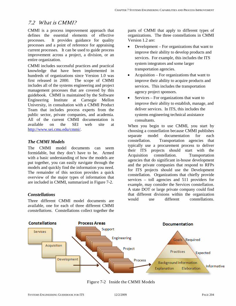
CHAPTER 7 SYSTEMS ENGINEERING CAPABILITIES AND PROCESS IMPROVEMENT
SYSTEMS ENGINEERING GUIDEBOOK FOR ITS 12/2/2009 PAGE 204
7.2 What is CMMI? CMMI is a process improvement approach that defines the essential elements of effective processes. It provides guidance for quality processes and a point of reference for appraising current processes. It can be used to guide process improvement across a project, a division, or an entire organization. CMMI includes successful practices and practical knowledge that have been implemented in hundreds of organizations since Version 1.0 was first released in 2000. The scope of CMMI includes all of the systems engineering and project management processes that are covered by this guidebook. CMMI is maintained by the Software Engineering Institute at Carnegie Mellon University, in consultation with a CMMI Product Team that includes process experts from the public sector, private companies, and academia. All of the current CMMI documentation is available on the SEI web site at http://www.sei.cmu.edu/cmmi/.
The CMMI model documents can seem formidable, but they don’t have to be. Armed with a basic understanding of how the models are put together, you can easily navigate through the models and quickly find the information you need. The remainder of this section provides a quick overview of the major types of information that are included in CMMI, summarized in
The CMMI Models
Figure 7-2.
Three different CMMI model documents are available, one for each of three different CMMI constellations. Constellations collect together the
parts of CMMI that apply to different types of organizations. The three constellations in CMMI Version 1.2 are:
Constellations
• Development – For organizations that want to improve their ability to develop products and services. For example, this includes the ITS system integrators and some larger transportation agencies.
• Acquisition – For organizations that want to improve their ability to acquire products and services. This includes the transportation agency project sponsors.
• Services – For organizations that want to improve their ability to establish, manage, and deliver services. In ITS, this includes the systems engineering technical assistance consultants.
When you begin to use CMMI, you start by choosing a constellation because CMMI publishes separate model documentation for each constellation. Transportation agencies that typically use a procurement process to deliver their ITS projects should start with the Acquisition constellation. Transportation agencies that do significant in-house development and the private companies that respond to RFPs for ITS projects should use the Development constellation. Organizations that chiefly provide services – toll agencies and 511 providers for example, may consider the Services constellation. A state DOT or large private company could find that different divisions within the organization would use different constellations.
Figure 7-2 Inside the CMMI Models

CHAPTER 7 SYSTEMS ENGINEERING CAPABILITIES AND PROCESS IMPROVEMENT
SYSTEMS ENGINEERING GUIDEBOOK FOR ITS 12/2/2009 PAGE 205
Figure 7-3 shows the three constellations and their relationships. As shown, the constellations overlap because processes like project planning, monitoring, and control are germane to all types
of organizations. These common areas are defined one time in the “CMMI Model Foundation” and included in all three constellations.
Figure 7-3 CMMI Constellations
Process areas are the main building blocks of each CMMI model. They are defined for each topic that CMMI covers and are allocated to constellations so that each constellation includes some common process areas (defined in the CMMI Model Foundation) and specific process areas that are unique to that constellation. These process areas cover the “waterfront” of successful
practices needed for systems acquisition, system development, and service provision.
Process Areas
Figure 7-4 identifies the 22 Process Areas that are in the Development constellation. The process areas are divided into four interrelated categories as shown. Process management occurs at the organizational level and defines and monitors the processes that are used by the organization and supports training and personnel development. The project management processes, in turn, support the engineering processes at the project level. Cross-cutting processes that support all levels are on the left side of the diagram. The Acquisition constellation process areas are related in a similar fashion as shown in Figure 7-5. The “Engineering” process category is replaced by an “Acquisition” process category in this model. The foundation Process Management, Project Management, and Support process areas are essentially the same in the two models. Similarly, the Services Constellation includes a set of Service Establishment and Delivery process areas that are supported by general Support, Project Management, and Process Management process areas.
Figure 7-4 Development Constellation Process Areas

CHAPTER 7 SYSTEMS ENGINEERING CAPABILITIES AND PROCESS IMPROVEMENT
SYSTEMS ENGINEERING GUIDEBOOK FOR ITS 12/2/2009 PAGE 206
Figure 7-5 Acquisition Constellation Process Areas
Process Area Documentation The bulk of the CMMI model is composed of the documentation for each process area. Figure 7-6 shows the types of information that are included in each process area and differentiates between information that is required, expected, and informative. As shown, only the process area goals are required. A set of expected practices are
associated with each goal. An organization does not have to implement the expected practices, but must be able to explain how their organization achieves the associated goals in another way. The great majority of process area documentation is informative; it is intended to increase understanding, but is not required.
Figure 7-6 Process Area Documentation
Table 7-1 shows an example of the documentation for the Configuration Management process area. As shown, a general goal statement is supported by several expected practices that are a bit more specific. These four succinct statements are supported by approximately four pages of informative documentation including detailed notes, typical word products, and typical supplier
deliverables that define and explain “baselines”, “configuration items”, “change management” and other key configuration management concepts. Overall, the Configuration Management process area includes 3 goals and seven expected practices that are supported by 10+ pages of documentation.
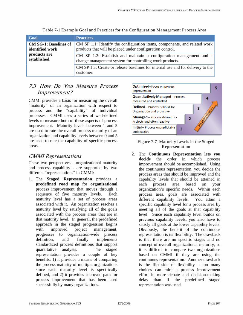
CHAPTER 7 SYSTEMS ENGINEERING CAPABILITIES AND PROCESS IMPROVEMENT
SYSTEMS ENGINEERING GUIDEBOOK ITS 12/2/2009 PAGE 207
Table 7-1 Example Goal and Practices for the Configuration Management Process Area
Goal Practices CM SG-1: Baselines of identified work products are established.
CM SP 1.1: Identify the configuration items, components, and related work products that will be placed under configuration control. CM SP 1.2: Establish and maintain a configuration management and a change management system for controlling work products. CM SP 1.3: Create or release baselines for internal use and for delivery to the customer.
7.3 How Do You Measure Process Improvement?
CMMI provides a basis for measuring the overall “maturity” of an organization with respect to process and the “capability” of individual processes. CMMI uses a series of well-defined levels to measure both of these aspects of process improvement. Maturity levels between 1 and 5 are used to rate the overall process maturity of an organization and capability levels between 0 and 5 are used to rate the capability of specific process areas.
CMMI Representations These two perspectives – organizational maturity and process capability - are supported by two different “representations” in CMMI: 1. The Staged Representation provides a
predefined road map for organizational process improvement that moves through a sequence of five maturity levels. Each maturity level has a set of process areas associated with it. An organization reaches a maturity level by satisfying all of the goals associated with the process areas that are in that maturity level. In general, the predefined approach in the staged progression begins with improved project management, progresses to organization-wide process definition, and finally implements standardized process definitions that support quantitative analysis. The staged representation provides a couple of key benefits: 1) it provides a means of comparing the process maturity of multiple organizations since each maturity level is specifically defined, and 2) it provides a proven path for process improvement that has been used successfully by many organizations.
Figure 7-7 Matur ity Levels in the Staged
Representation
2. The Continuous Representation lets you decide the order in which process improvement should be accomplished. Using the continuous representation, you decide the process areas that should be improved and the capability levels that should be attained in each process area based on your organization’s specific needs. Within each process area, goals are associated with different capability levels. You attain a specific capability level for a process area by meeting all of the goals at that capability level. Since each capability level builds on previous capability levels, you also have to satisfy all goals at the lower capability levels. Obviously, the benefit of the continuous representation is its flexibility. The drawback is that there are no specific stages and no concept of overall organizational maturity, so it is difficult to compare two organizations based on CMMI if they are using the continuous representation. Another drawback is the flip side of flexibility – too many choices can mire a process improvement effort in more debate and decision-making delay than if the predefined staged representation was used.

CHAPTER 7 SYSTEMS ENGINEERING CAPABILITIES AND PROCESS IMPROVEMENT
SYSTEMS ENGINEERING GUIDEBOOK ITS 12/2/2009 PAGE 208
Figure 7-8 Capability Levels in the Continuous
Representation
A quick comparison of Figure 7-7 and Figure 7-8 hints at the close parallels between the two representations, particularly at the higher levels. In both representations, the focus through level 2 is on process performance at a project level. At levels 3 and above, the focus shifts to the organization with institutionalization and management of the process at the organizational level. In ITS, the flexibility of the continuous representation makes it an attractive representation for many organizations considering a process improvement initiative. As you take advantage of the flexibility of the continuous representation, it is also important to understand the “standard” path to process improvement that is embedded in the staged representation. This path begins with a focus on project management and applying processes on selected projects, adding organizational policies, training and resources to support the processes, and then documenting and managing proven processes at the organizational level. This proven path provides a good reference and a starting point for your process improvement plan.
There are two key reasons to perform an appraisal: 1) to accurately diagnose internal process problems and areas for process improvement, and 2) to create a benchmark for process capability/maturity that can be used to rate the organization. In order to measure your organization’s process capability, you compare your organization’s processes to CMMI or another baseline process model. Such an examination by a trained team of professionals using CMMI is called an appraisal. While the terms appraisal and assessment are used interchangeably in
everyday conversation, there is an important distinction within CMMI. An assessment is an appraisal that an organization does internally to support process improvement.
Appraisals
Three types of appraisals are defined in the SEI document “Appraisal Requirements for CMMI” [ARC]:
• Class A – Full comprehensive method, used for benchmarking
• Class B – Less comprehensive, partial self- assessment
• Class C – Quick look [check specific areas]
There are 40 requirements and constraints for process appraisals included in ARC. Only the more comprehensive (expensive) Class A appraisal that meets all 40 ARC requirements can be used to generate benchmark capability/maturity levels that are published by SEI. The Class B and Class C appraisals require fewer resources and still support process improvement objectives. More information on the CMMI appraisal program can be found on the SEI website at http://www.sei.cmu.edu/cmmi/tools/appraisals/. While an experienced consultant can be hired to perform an appraisal, informal assessments may also be performed in-house by another department or quality team with assessment capabilities. An internal assessment is carried out in much the same way as a formal CMMI appraisal, but the results are not officially reported to SEI as they are in a Class A appraisal. An internal assessment is less political and likely to be more realistic than a formal appraisal that gets advertised outside the organization. Most transportation agencies, being new to CMMI, should keep it simple initially and start with an assessment geared towards process improvement. Any appraisal should begin with an understanding of the sponsor’s goals and objectives for the appraisal and a clear definition of the portion of the organization to be appraised. Specific projects are identified and a combination of document reviews and interviews are used to understand the processes that are currently defined and how well each appraised project conforms to the defined processes. Once the results are validated, a report is generated that identifies the level of maturity and/or areas for process improvement. The cost of CMMI appraisals varies greatly and depends upon the type of appraisal, tailoring

CHAPTER 7 SYSTEMS ENGINEERING CAPABILITIES AND PROCESS IMPROVEMENT
SYSTEMS ENGINEERING GUIDEBOOK ITS 12/2/2009 PAGE 209
requested, and size of the team. A minimum cost would be approximately $30K for a Class C appraisal to several hundred thousands of dollars for a full Class A appraisal. Formal appraisals are common for Defense, Federal Aviation Administration, and Department of Energy firms. These appraisals are also being performed for banking and some information technology firms. To date, few ITS firms have subjected their processes to CMMI appraisals that could lead to organizational comparisons, although a few ITS firms have undertaken their own assessments. Internal assessments have also been performed by a few state DOTs. FHWA has developed a Systems Engineering for ITS Workshop that includes a process improvement review that focuses on systems engineering processes related to 23 CFR 940 requirements. This assessment is a good way for transportation agencies to start a process improvement initiative since it is provided by FHWA at no cost to the agency and is focused on those process areas most germane to ITS and the underlying 23 CFR 940 requirements.
7.4 How Do You Use CMMI for Internal Process Improvement?
Improving an organization’s processes is easier said than done. Success requires management commitment, a plan, and a sustained cooperative effort. The comprehensive, detailed highway design procedures that are in place in every state are the result of years of collaborative effort. Augmenting these processes to incorporate systems engineering processes for ITS is really a project in itself, and should be managed as such. The following process improvement steps are adapted from the SEI recommendations and augmented to identify resources and provide discussion specific to ITS. 1. Obtain Management Support. The process
improvement effort must be supported by senior management since it will require staff time and resources to implement and will impact the way people do their jobs. In ITS, Title 23 CFR 940 (“FHWA Rule 940”) provides motivation for management since it requires use of systems engineering processes for ITS projects. An FHWA SE for ITS Workshop is also available that can include an executive presentation on the merits of improved systems engineering processes.
Executive presentations including return on investment information are also available on the SEI web site.
2. Prepare Organization for Process Improvement. Building on the materials used to secure management support, establish a compelling case for the effort including rationale, expected benefits, and costs. Build an initial plan for the effort. Take training, for example, an Introduction to CMMI course and/or the Systems Engineering for ITS Workshop offered by FHWA. With respect to CMMI, the CMMI constellation and representation (staged or continuous) are initially selected.
3. Form a Process Group. This group will coordinate the process improvement activity across the organization and provide input from each division/group impacted by the process improvement. Initially, this group will assist in establishing process improvement priorities based on organizational objectives, selecting priority process areas and initial capability objectives. In public agencies, this group must include ITS project management and staff and “the owners” of existing process documentation that will be impacted by the process improvements.
4. Assess Where You Are. Assess your organization’s processes and do an informal gap analysis to identify where process improvement is necessary. A Process Improvement Review is provided by FHWA as part of the Systems Engineering for ITS Workshop. Alternatively, a self-assessment can be performed internally by gathering existing process data and project documentation and interviewing project managers and technical staff that are involved with ITS project development.
5. Define Where you are Going. Prioritize the process areas to address and complete your process improvement plan. A “Capability Profile” is a cornerstone of a CMMI-based

CHAPTER 7 SYSTEMS ENGINEERING CAPABILITIES AND PROCESS IMPROVEMENT
SYSTEMS ENGINEERING GUIDEBOOK ITS 12/2/2009 PAGE 210
process improvement plan. The capability profile identifies: 1) the process areas to be addressed, 2) the current capability level for each selected process area, and 3) the target capability level for each process area. A capability profile is easily communicated using a bar chart like the one presented in Figure 7-9.
Figure 7-9 CMMI Capability Profile
It is important to note that the target should not be to achieve level 5 in all process areas. An organization may elect to stay at level 2 or 3 in process areas that are less critical and focus on improving capability in only the highest priority areas that most directly impact project cost, schedule, and performance.
6. Communicate and Coordinate. Share the plan with all affected parties and listen to their comments. Continue to keep everyone informed as the process improvements are implemented.
7. Track Your Progress. Create a periodic report that demonstrates progress in reaching the process improvement targets established in the plan. You can also elect to perform a more formal process appraisal for an objective evaluation of your organization’s processes at this point. If a process improvement goal is to achieve a specific maturity rating, then a CMMI Class A appraisal can be performed; otherwise, periodic internal assessments can continue to be used to support process improvement. Refine the plan over time so that it continues to represent the organization’s process improvement objectives.
The following table identifies the suggested minimum capabilities profile for system owners, systems engineering consultants, and the development team. The table uses the Acquisition constellation for the System Owner and the Development constellation for the SETA consultant and Development Team.
Table 7-1 Suggested Minimum Capabilities Table for ITS
CMMI
Process Areas
Systems Owner
[Project Sponsor]
Systems Engineering Technical Assistance: [In-house, Consultant,
System Manager]
Development Team
[In-house, Systems Integrator]
Acquisition Acquisition Requirements
Development 2
Agreement Management 2 Solicitation and Supplier Agreement Management
2
Acquisition Technical Management 2 Acquisition Verification 2 Acquisition Validation 2
Engineering Requirements Management 2 2 2

CHAPTER 7 SYSTEMS ENGINEERING CAPABILITIES AND PROCESS IMPROVEMENT
SYSTEMS ENGINEERING GUIDEBOOK ITS 12/2/2009 PAGE 211
CMMI
Process Areas
Systems Owner
[Project Sponsor]
Systems Engineering Technical Assistance: [In-house, Consultant,
System Manager]
Development Team
[In-house, Systems Integrator]
Requirements Development 2 2 Technical Solution 2 2 Product Integration 2 2
Verification 2 2 Validation 2 2
Project Management Project Planning 2 2 2
Project Monitoring and Control 2 1 2 Supplier Agreement Management 1 2 Integrated Project Management 1 1 2
Risk Management 3 2 3 Quantitative Project Management
Support Configuration Management 3 1 3
Process and Product Quality Assurance
2 1 2
Measurement and Analysis 1 2 2 Decision Analysis and Resolution 1 2 2 Causal Analysis and Resolution 1 2 2
Process Management Organizational Process Definition 2 1 3
Organizational Process Focus 2 1 2 Organizational Training 2 1 2 Organizational Process
Performance
Organizational Innovation and Deployment
Legend for Table
Level 1 Performed Level 2 Managed Level 3 Defined
7.5 How Do You Use CMMI to Support Contracting?
An ITS project sponsor could develop a Request for Qualifications [RFQ] that includes a CMMI maturity level for a systems development team as one of the evaluation criterion. Assuming that the competing firms have been formally appraised, this would provide the project sponsor additional assurance of the contractor’s systems engineering capabilities. Remember that a maturity level normally refers to a specific group
within a company. It does not apply to the entire company unless the whole company performed at the desired maturity level on the appraised projects. When reviewing the qualifications, make sure the team proposed at a maturity level is the team that was appraised. In transportation today, few, if any, ITS development firms have had a Class A CMMI appraisal, so a maturity rating would have to be optional if it is included in the evaluation criteria. This creates a “chicken and egg” situation since firms will not be as motivated to undertake

CHAPTER 7 SYSTEMS ENGINEERING CAPABILITIES AND PROCESS IMPROVEMENT
SYSTEMS ENGINEERING GUIDEBOOK ITS 12/2/2009 PAGE 212
process improvement if process capability is not considered by agencies in their ITS project procurements. Since there has not been a significant push from the agencies to make this happen, development firms have not offered this in their proposals. Hopefully, as a result of this Guidebook, criteria for CMMI levels of maturity will start showing up in RFQ’s, RFP’s, and RFI’s. Over time, it should be common for ITS development teams to perform at least at level 2 and preferably at level 3. This will provide the project sponsor the confidence that the selected development team will have the capability to perform well and reduce project risk. When an organization makes the decision to achieve a CMMI maturity level 2, it requires from 1-2 years to document, train for, and implement the needed processes. Then, the formal appraisal takes place after the level 2 practices have been applied to a real project. This may take another 2 years [assuming an 18-24 month project]. In all, it may take from 3-5 years for a system integrator starting at level 0 to be assessed and recognized as being at CMMI level 2. In the near term, while formal CMMI ratings are uncommon in ITS, evidence of progress towards good systems engineering processes should still be included in ITS project proposals. For example, systems engineering processes should be clearly described in the proposal including a discussion of the maturity of these processes (e.g., they are documented and have been used on previous projects). Professional certifications for key personnel such as the INCOSE Certified Systems Engineering Professional (CSEP) and Project Management Institute’s Project Management Professional (PMP) may also be considered. The systems engineering processes that are described in this Guidebook can reduce risk on your ITS projects, but the benefits will only be realized if the processes are documented and used in a systematic way on each ITS project. CMMI is a comprehensive tool for process improvement that can help with the process improvement efforts within your organization. Transportation organizations that are relatively new to systems engineering and CMMI should keep it simple at the start, focusing on those process areas that are most critical to their bottom line and using internal assessments to understand where they are and where they would like to be. As the transportation agencies and firms that support these agencies improve their processes over time, more formal appraisals can be used to verify
process maturity and guide on-going process improvement efforts.

SECTION 1
SYSTEMS ENGINEERING GUIDEBOOK ITS 12/2/2009 PAGE 213
8 Appendices These appendices contain a wide variety of useful information that summarize and supplement the earlier parts of the Guidebook. The sections on Glossary, Definition of Terms, and References conveniently summarize, in one place, all the items used in the guidebook. The sections on Contract Guidance and Systems Engineering Documentation Guidance supplement the material found in other parts of the Guidebook and provide practical, real-world guidance to the reader. The following sections may be found in the appendices: Glossary and acronyms used in the Guidebook. Like any discipline, ITS has its own language.
Communications between practitioners will be clearer if the language used is consistent. References to other documents contained in the Guidebook. These references give the reader the ability
to explore subjects of specific interest in more detail. Topics relating to contract guidance that are of special importance to Intelligent Transportation Systems
is provided. The two topics covered are preparation of a Request for Proposal and recommendations on Intellectual Property Rights for software and documentation.
Systems Engineering Documentation Guidance for commonly occurring documents in the systems engineering processes. These sections provide information on the purpose and content of several technical documents that, in one form or another, most ITS projects will need. They also show how these documents are tailored to the specific needs of the project.

SECTION 8 APPENDICES
SYSTEMS ENGINEERING GUIDEBOOK ITS 12/2/2009 PAGE 214
8.1 Glossary and Acronyms This glossary and acronym list includes all the key terms and acronyms used in this guidebook; as well as others that often appear in systems engineering. While these are many of the definitions that can be used, each project will have its own set of terms that need to be defined and adopted as part of the project formation and initial tasks.
8.1.1 Glossary Acceptance: An action by an authorized representative of the acquirer by which the acquirer assumes ownership of products as a partial or complete performance of contract. Acceptance criteria: The criteria a product must meet to successfully complete a test phase or meet delivery requirements. Acceptance test: Formal testing conducted to determine whether or not a system satisfies its acceptance criteria and to enable the acquirer to determine whether or not to accept the system. Acquirer: An organization that procures products for itself or another organization. Appraisal: In CMMI, an examination of one or more processes by a trained team of professionals using an appraisal reference model as the basis for determining, at a minimum, strengths and weaknesses. (See also assessment.) Approval: Written notification by an authorized representative of the acquirer that the developer’s plans, design, or other aspects of the project appear to be sound and can be used as the basis for further work. Such approval does not shift responsibility from the developer to meet contractual requirements. Architecture: The organizational structure of a system, identifying its components, their interfaces, and a concept of execution among them. Assembly: A number of parts or sub-assemblies, or any combination thereof joined together, to perform a specific function and capable of disassembly. Assessment: In CMMI, an appraisal that an organization does internally for the purposes of process improvement. Audit: An independent examination of a work product/process or set of work products/processes to assess compliance with specifications, standards, contractual agreements, or other criteria. Authentication: The procedure [essentially approval] used by the approval authority in verifying that specification content is acceptable. Authentication does not imply acceptance or responsibility for the specified item to perform successfully. Baseline: An approved product at a point in time. Any changes made to this product must go through a formal change process. Capability Level: Achievement of process improvement within an individual process area. A capability level is defined by appropriate specific and generic practices for a process area. Certification: A process, which may be incremental, by which a contractor provides evidence to the acquirer that a product meets contractual or otherwise specified requirements. Commercial off the shelf: see COTS Components: Components are the named "pieces" of design and/or actual entities [sub-systems, hardware units, software units] of the system/sub-system. In system/sub-system architectures, components consist of sub-systems [or other variations], hardware units, software units, and manual operations. Computer database: see database. Computer hardware: Devices capable of accepting and storing computer data, executing a systematic sequence of operations on computer data, or producing control outputs. Such devices can perform substantial interpretation, computation, communication, control, or other logical functions. Computer program: A combination of computer instructions and data definitions that enable computer hardware to perform computational or control functions. Computer software: See software. Concept [project concept]: A high-level conceptual project description, including services provided and the operational structure.

SECTION 8 APPENDICES
SYSTEMS ENGINEERING GUIDEBOOK ITS 12/2/2009 PAGE 215
Concept exploration: The process of developing and comparing alternative conceptual approaches to meeting the needs that drive the project. Concept of Operations: A document that defines the way the system is envisioned to work from multiple stakeholder viewpoints [Users including operators, maintenance, management]. Configuration item [CI]: A product such as a document or a unit of software or hardware that performs a complete function and has been chosen to be placed under change control. That means that any changes that are to be made must go through a change management process. A baseline is a configuration item. Configuration management: A discipline applying technical and administrative direction and surveillance to identify and document the functional and physical characteristics of Configuration Items [CI’s]; audit the CI’s to verify conformance to specifications, manage interface control documents and other contract requirements control changes to CI’s and their related documentation; and record and report information needed to manage CI’s effectively, including the status of proposed changes and the implementation status of approved changes. Configuration Management Plan: A plan defining the implementation [including policies and methods] of configuration management on a particular program/project. Contract: A mutually binding legal relationship obligating a seller to furnish the supplies or services [including construction] and a buyer to accept and pay for them. It includes all types of commitments, in writing, that obligate the buyer to an expenditure of appropriate funds. In addition to bilateral agreements, contracts include, but are not limited to, awards and notices of awards; job orders or task letters issued under purchase orders under which the contract becomes effective by written acceptance or performance; and bilateral modifications. Contractor: An individual, partnership, company, corporation, association or other service, having a contract with a buyer for the design, development, manufacture, maintenance, modification, or supply of items under the terms of a contract. Control gates: Formal decision points along the life cycle that are used by the system’s owner and stakeholders to determine if the current phase of work has been completed and that the team is ready to move into the next phase of the life cycle. Commercial off-the-shelf software: Commercially available applications sold by vendors through public catalogue listings, not intended to be customized or enhanced. [Contract-negotiated software developed for a specific application is not COTS software.] Cross-cutting activities: Enabling activities used to support one or more of the life cycle process steps. Data: Recorded information, regardless of medium or characteristics, of any nature, including administrative, managerial, financial, and technical. Data product: Information that is inherently generated as the result of work tasks cited in a Statement of Work [SOW] or in a source document invoked in the contract. Such information is produced as a separate entity [for example, drawing, specification, manual, report, records, and parts list]. Database: A collection of related data stored in one or more computerized files in a manner that can be accessed by users or computer programs via a database management system. Database management system: An integrated set of computer programs that provide the capabilities needed to establish, modify, make available, and maintain the integrity of a database. Decomposition: The process of successively breaking down the system into components that can be built or procured. Functional and physical decomposition are the key activities that are used. Functional decomposition is breaking a function down into its smallest parts. For example, the function ramp metering decomposes into a number of sub-functions, e.g. detection, meter rate control, main line metering, ramp queuing, time of day, and communications. Physical decomposition defines the physical elements needed to carry out the function. For example, the ramp metering physical decomposition includes loops or video detection, WWV time [world wide standard clock for accurate time], fiber or twisted pair for communications, 2070 or 170 controllers, and host computer. Design: Those characteristics of a system or components that are selected by the developer in response to the requirements.

SECTION 8 APPENDICES
SYSTEMS ENGINEERING GUIDEBOOK ITS 12/2/2009 PAGE 216
Detailed Design Document: The product baseline used to develop the hardware and software components of the system. Developer: An organization that develops products ["develops" may include new development, modification, reuse, reengineering, maintenance, or any other activity that results in products] for itself or another organization. Development model: A specific portion of the life cycle model that relates to the definition, decomposition, development, and implementation of a system or a part of a system. Development strategy: The way the development and deployment of the overall system will be carried out. For example, an evolutionary development strategy means that the system will be developed and deployed in multiple segments over time. These pieces are complete functional units that will perform independently from other functional pieces. Incremental development is the development of pieces that are done concurrently or nearly concurrently by the same or different development teams. Elicitation: The process to draw out, to discover and to make known so to gain knowledge and information, often used in defining needs. Enabling products: Products that enable the end product to be developed, supported, and maintained. For example, these products typically are the software compilers, prototypes, development workstations, plans, specifications, requirements, and training materials. End products: Products that perform the desired capability e.g. the hardware, software, communications, and databases. End-item: A deliverable item that is formally accepted by the acquirer in accordance with requirements of a detail specification. Evaluation: The process of determining whether an item or activity meets specified criteria. Evolutionary development: Breaking a project down into parts and developing them in serial fashion. Feasibility assessment: A pre-development activity to evaluate alternative system concepts, selects the best one, and verifies that it is feasible within all of the project and system constraints. Firmware: The combination of a hardware device and computer instructions and/or computer data that resides as read-only software on the hardware device. Gap analysis: A technique to assess how far current [legacy] capabilities are from meeting the identified needs, to be used to prioritize development activities. This is based both on how far the current capabilities are from meeting the needs [because of insufficient functionality, capabilities, performance or capacity] and whether the need is met in some places and not others. Hardware: Articles made of material, such as aircraft, ships, tools, computers, vehicles, fittings, and their components [mechanical, electrical, electronic, hydraulic, and pneumatic]. Computer software and technical documentation are excluded. Integrated product team: A team consisting of agency and contractor representatives working together. Integrity: A system characteristic that means that the system’s functional, performance, physical, and enabling products are accurately documented by its requirements, design, and support specifications. Intelligent Transportation Systems: A broad range of diverse technologies which, when applied to our current transportation system, can help improve safety, reduce congestion, enhance mobility, minimize environmental impacts, save energy, and promote economic productivity. ITS technologies are varied and include information processing, communications, control, and electronics. Interface: The functional and physical characteristics required to exist at a common boundary - in development, a relationship among two or more entities [such as software-software, hardware-hardware, hardware-software, hardware-user, or software-user]. Interface control: Interface control comprises the delineation of the procedures and documentation, both administrative and technical, contractually necessary for identification of functional and physical characteristics between two or more configuration items that are provided by different contractors/acquiring agencies, and the resolution of the problems thereto. Item: A non-specific term used to denote any product, including systems, sub-systems, assemblies, subassemblies, units, sets, accessories, computer programs, computer software, or parts. Legacy system: The existing system to which the upgrade or change will be applied.

SECTION 8 APPENDICES
SYSTEMS ENGINEERING GUIDEBOOK ITS 12/2/2009 PAGE 217
Life cycle: The end-to-end process from conception of a system to its retirement or disposal. Life cycle model: A representation of the steps involved in the development and other phases of an ITS project. Market packages: Potential products or sub-systems that address specific services [as used in an ITS architecture]. Maturity Level: Degree of process improvement across a predefined set of process areas in which all goals in the set are attained. (See also capability level.) Metrics : Measures used to indicate progress or achievement. Model: An abstraction of reality. Examples: A road map is an abstraction of the real road network. A globe is a model of the world. A simulation is a dynamic model of a time sequence of events. Module: A self-contained part of a hardware item designed as a single replaceable unit, with a specific integral electronic function. It should require no installation other than mechanical mounting and completion of electrical connection. National ITS Architecture: A general framework for planning, defining, and integrating ITS. It was developed to support ITS implementations over a 20-year time period in urban, interurban, and rural environments across the country. The National ITS Architecture is available as a resource for any region and is maintained by the USDOT independently of any specific system design or region in the nation. Needs assessment: An activity accomplished early in system development to ensure that the system will meet the most important needs of the project’s stakeholders, specifically that the needs are well understood, de-conflicted, and prioritized. Non-conformance: The failure of a unit or product to conform to specified requirements. Operational baseline: The system that is currently in use, including all of the design, development, test, support, and requirements documentation. Operational concept: The roles and responsibilities of the primary stakeholders and the systems they operate. Part: One piece, or two or more pieces joined together which are not normally subjected to disassembly without destruction or impairment of designed use [examples: gear, screws, transistors, capacitors, integrated circuits]. Performance: A quantitative measure characterizing a physical or functional attribute relating to the execution of a mission/operation or function. Policy: A guiding principle, typically established by senior management, which is adopted by an organization or project to influence and determine decisions. Process: An organized set of activities Process Area: A cluster of related practices in an area that, when implemented collectively, satisfies a set of goals considered important for making improvement in that area. All CMMI process areas are common to both continuous and staged representations. Product: A product is a given set of items. The set could consist of system, sub-system, hardware or software items, and their documentation. Project: An undertaking requiring concerted effort, which is focused on developing and/or maintaining a specific product. The product may include hardware, software, and other components. Typically, a project has its own funding, cost accounting, and delivery schedule with the acquirer [customer]. Project architecture: High-level design Project life cycle: See Life cycle Project Plan: A description [what is to be done, what funds are available, when it will be done and by whom] of the entire set of tasks that the project requires. Qualification testing: Testing performed to demonstrate to the acquirer that an item, system, or sub-system meets its specified requirements. Quality assurance: A planned and systematic pattern of all actions necessary to provide adequate confidence that management, technical planning, and controls are adequate to establish correct technical requirements

SECTION 8 APPENDICES
SYSTEMS ENGINEERING GUIDEBOOK ITS 12/2/2009 PAGE 218
for design and manufacturing. And to manage design activity standards, drawings, specifications, or other documents referenced on drawings, lists or technical documents. Reengineering: The process of examining and altering an existing system to reconstitute it in a new form. This may include reverse engineering [analyzing a system and producing a representation at a higher level of abstraction, such as design from code], restructuring [transforming a system from one representation to another at the same level of abstraction], recommendation [analyzing a system and producing user and support documentation], forward engineering [using software products derived from an existing system, together with new requirements, to produce a new system], and translation [transforming source code from one language to another or from one version of a language to another]. Regional ITS Architecture: A specific regional framework for ensuring institutional agreement and technical integration for the implementation of ITS projects in a particular region. Regression Testing: Is a process that tests not only the area of change but also tests those areas that were not changed but are affected by the change. Requirements: The total consideration as to WHAT is to be done [functional], HOW well it is to perform [performance], and under WHAT CONDITIONS it is to operate. [Environmental and non-functional]. Reverse engineering: The process of documenting an existing Intelligent Transportation Systems functional [what it does – requirements], physical [how it does it – design], and support [the way it was built and maintained – enabling products] characteristics. Risk management: An organized process to identify what can go wrong, to quantify and access associated risks, and to implement/control the appropriate approach for preventing or handling each risk. Software: Computer programs and computer databases. Note: Although some definitions of software include documentation, it is now limited to the definition of computer programs and computer databases. Software development: A set of activities that result in software products. Software development may include new development, modification, reuse, re-engineering, maintenance, or any other activities that result in software products. Specification: A document that describes the essential technical requirements for items, materials or services including the procedures for determining whether or not the requirements have been met. Stakeholders: The people for whom the system is being built, as well as anyone who will manage, develop, operate, maintain, use, benefit from, or otherwise be affected by the system. Statement of Work: A document primarily for use in procurement, which specifies the work requirements for a project or program. It is used in conjunction with specifications and standards as a basis for a contract. The SOW will be used to determine whether the contractor meets stated performance requirements. Subcontractor: An individual, partnership, corporation, or an association that contracts with an organization [i.e., the prime contractor] to design, develop, and/or manufacture one or more products. Suppliers: The term 'suppliers' includes contractors, sub-contractors, vendors, developers, sellers or any other term used to identify the source from which products or services are obtained. Synthesis: The translation of input requirements [including performance, function, and interface] into possible solutions [resources and techniques] satisfying those inputs. This defines a physical architecture of people, product, and process solutions for logical groupings of requirements [performance, functions, and interface] and their designs for those solutions. System elements: A system element is a balanced solution to a functional requirement or a set of functional requirements and must satisfy the performance requirements of the associated item. A system element is part of the system [hardware, software, facilities, personnel, data, material, services, and techniques] that, individually or in combination, satisfies a function [task] the system must perform. System: An integrated composite of people, products, and processes, which provide a capability to satisfy a stated need or objective. Systems engineering: An inter-disciplinary approach and a means to enable the realization of successful systems. Systems engineering requires a broad knowledge, a mindset that keeps the big picture in mind, a facilitator, and a skilled conductor of a team.

SECTION 8 APPENDICES
SYSTEMS ENGINEERING GUIDEBOOK ITS 12/2/2009 PAGE 219
System specification: A top level set of requirements for a system. A system specification may be a system/sub-system specification, Prime Item Development Specification, or a Critical Item Development Specification. Tailoring: Planning systems engineering activities that are appropriate and cost-effective for the size and complexity of the project. It may be based on cost, size, the number of stakeholders, the supporting relationships between them, complexity of systems [large number of interfaces to other systems, a large number of functions to perform, or the degree of coupling between systems.], level of ownership of system products [custom development of software owned by the agency or commercial off the shelf products], existing software products, resources, risks. Technical reviews: A series of system engineering activities by which the technical progress on a project is assessed relative to its technical or contractual requirements. The formal reviews are conducted at logical transition points in the development effort to identify and correct problems resulting from the work completed thus far before the problem can disrupt or delay the technical progress. The reviews provide a method for the contractor and procuring activity to determine that the identification and development of a CI have met contract requirements. Testable: A requirement or set of requirements is considered to be testable if an objective and feasible test can be designed to determine whether each requirement has been met. Trade-off Study: An objective evaluation of alternative requirements, architectures, design approaches, or solutions using identical ground rules and criteria. User: The organization[s] or persons within those organizations who will operate and/or use the system for its intended purpose. User services: A catalog of features that could be provided by an ITS project [as used in an ITS architecture]. Validation: The process of determining that the requirements are the correct requirements and that they form a complete set of requirements this is done a the early stages of the development process. Validation of the end product or system determines if the system meets the users needs. Vendor: A manufacturer or supplier of an item. Verification: The process of determining whether or not the products of a given phase of the system/software life cycle fulfill the requirements established during the preceding phase. Work breakdown structure: A product-oriented listing, in family tree order, of the hardware, software, services, and other work tasks, which completely defines a product or program. The listing results from project engineering during the development and production of a materiel item. A WBS relates the elements of work to be accomplished to each other and to the end product.

CHAPTER 8.1.2 ACRONYMS
SYSTEMS ENGINEERING GUIDEBOOK ITS 12/2/2009 PAGE 220
8.1.2 Acronyms AAA American Automobile Association AASHTO American Association of State Highway and Transportation Officials AIAA American Institute of Aeronautics and Astronautics ANSI American National Standards Institute ASTM American Society for Testing and Materials ATIS Advanced Transportation Information System ATMS Advanced Transportation Management System C2C Center to Center C2F Center To Field CAIV Cost As an Independent Variable CCTV Closed-Circuit Television CDR Critical Design Review CE Concept Exploration CEA Consumer Electronics Association CFR Code of Federal Regulations CG Control Gate CI Configuration Item CM Configuration Management CMM Capability Maturity Model CMMI Capabilities Maturity Model Integrated CMS Changeable Message Sign COCOMO Constructive Cost Model ConOps Concept of Operations CORBA Common Object Request Broker Architecture COTS Commercial Off-The-Shelf CR Change Request DATEX Data Exchange DBMS Database Management System DDR Detail Design Review DOT Department of Transportation ECP Engineering Change Proposal EDI Electronic Data Interchange EIA Electronic Industries Association FAR Federal Acquisition Regulation FCA Functional Configuration Audit FHWA Federal Highway Administration FPA Function Point Analysis FSR Feasibility Study Report FTP File Transfer Protocol GUI Graphical User Interface IAW In Accordance With HLD High-Level Design ICD Interface Control Documentation

CHAPTER 8.1.2 ACRONYMS
SYSTEMS ENGINEERING GUIDEBOOK ITS 12/2/2009 PAGE 221
ICWG Interface Control Working Group IEEE Institute of Electrical and Electronics Engineers IKIWISI I Know It When I See It INCOSE International Council of Systems Engineering [circa 1994] IPT Integrated Product Teams ISO International Organization for Standardization IT Information Technology ITE Institute of Transportation Engineers ITIP Interregional Transportation Improvement Plan ITS Intelligent Transportation System[s] IV&V Independent Verification and Validation KPP Key Performance Parameter MOE Measure of Effectiveness MOP Measure of Performance MPO Metropolitan Planning Organization NA Not Applicable NASA National Aeronautics and Space Administration NCOSE National Council on Systems Engineering [now INCOSE] NDI Non-Developmental Item NEMA National Electrical Manufacturers Association NIST National Institute of Standards and Technology NTCIP National Transportation Communications for ITS Protocol O&M Operations & Maintenance ORB Object Request Brokers [programming middleware] PD Product Development PDR Preliminary Design Review PM Program Manager PMI Project Management Institute PPP Point-to-Point Protocol QFD Quality Function Deployment RFP Request for Proposal RFQ Request for Quotation RTIP Regional Transportation Improvement Plan ROW Right Of Way SAE Society of Automotive Engineers SDR System Design Review SE Systems Engineering SEI Software Engineering Institute [Carnegie Mellon University] SEMP Systems Engineering Management Plan SERF Systems Engineering Review Form SETA Systems Engineering Technical Assistance SI Software Item SOW Statement of Work SRR System Requirements Review STIP Statewide Transportation Improvement Plan

CHAPTER 8.1.2 ACRONYMS
SYSTEMS ENGINEERING GUIDEBOOK ITS 12/2/2009 PAGE 222
SW Software T & E Test & Evaluation TIP Transportation Improvement Plan TMC Traffic Management Center TR Technical Review TRR Test Readiness Review UML Unified Modeling Language WAN Wide Area Network WBS Work Breakdown Structure XML Extensible Mark-up Language

CHAPTER 8.2.1 Systems Engineering References
SYSTEMS ENGINEERING GUIDEBOOK ITS 12/2/2009 PAGE 223
8.2 Systems Engineer ing Resources The following is a compilation of systems engineering, requirements and ITS references which will be helpful to the reader. This is organized with general systems engineering texts, followed by requirements engineering texts, then studies and papers, and finally ITS references. 8.2.1 Systems Engineer ing References Title: INCOSE Systems Engineering Handbook Version v3.1 Author: INCOSE Copyright: 2007 Publisher: INCOSE. ISBN: Comment: This is the subject matter basis for the INCOSE CSEP certification. Title: Introduction to Systems Engineering Author: Andrew P. Sage and James E. Armstrong , Jr. Copyright: 2000 Publisher: Wiley ISBN: 0-471-02766-9 Comment: This is a good introductory college level textbook. It has problem sets at the end of each section. There are also many bibliographic references for each section. Title: The Engineering and Design of Systems: Models and Methods Author: Dennis M. Buede Copyright: 2000 Publisher: Wiley ISBN: 0-471-28225-1 Comment: This is a good advanced college level textbook. It has problem sets at the end of each section. There are also many bibliographic references for each section. Title: Handbook of Systems Engineering and Management Author: Andrew P. Sage and William B. Rouse Copyright: 1999 Publisher: Wiley ISBN: 0-471-15405-9 Comment: This is a compendium of works from 40 contributing authors. At the end of each chapter are lists of additional references and a bibliography supporting the work. Title: Systems Engineering Guidebook: A Process for Developing Systems and Products Author: James N. Martin, A. Terry Bahill Copyright: 1999 Publisher: Wiley ISBN: 0849378370 Comment: This is a compendium of works from many contributing authors. Title: Systems Engineering and Analysis Author: Benjamin S. Blanchard and Wolter J. Fabrycky Copyright: 1998 Publisher: Prentice Hall ISBN: 0131350471 Comment: Title: Systems Engineering Management Author: Benjamin S. Blanchard
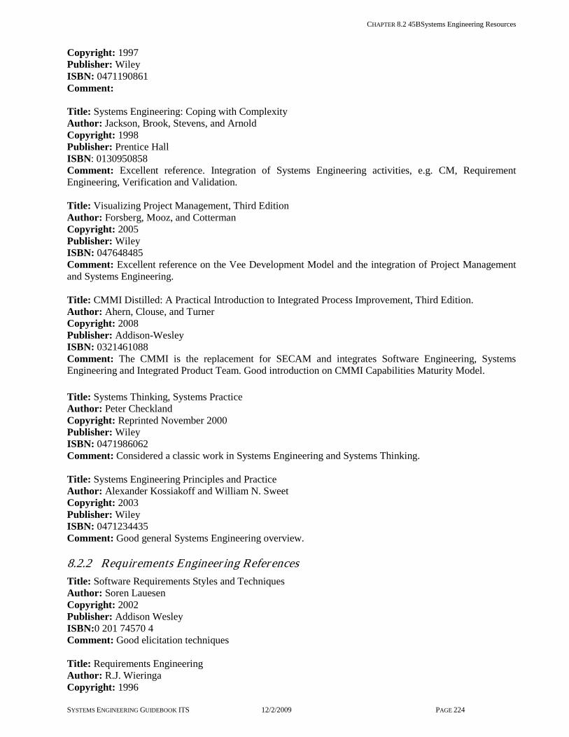
CHAPTER 8.2 45BSystems Engineering Resources
SYSTEMS ENGINEERING GUIDEBOOK ITS 12/2/2009 PAGE 224
Copyright: 1997 Publisher: Wiley ISBN: 0471190861 Comment: Title: Systems Engineering: Coping with Complexity Author: Jackson, Brook, Stevens, and Arnold Copyright: 1998 Publisher: Prentice Hall ISBN: 0130950858 Comment: Excellent reference. Integration of Systems Engineering activities, e.g. CM, Requirement Engineering, Verification and Validation. Title: Visualizing Project Management, Third Edition Author: Forsberg, Mooz, and Cotterman Copyright: 2005 Publisher: Wiley ISBN: 047648485 Comment: Excellent reference on the Vee Development Model and the integration of Project Management and Systems Engineering. Title: CMMI Distilled: A Practical Introduction to Integrated Process Improvement, Third Edition. Author: Ahern, Clouse, and Turner Copyright: 2008 Publisher: Addison-Wesley ISBN: 0321461088 Comment: The CMMI is the replacement for SECAM and integrates Software Engineering, Systems Engineering and Integrated Product Team. Good introduction on CMMI Capabilities Maturity Model. Title: Systems Thinking, Systems Practice Author: Peter Checkland Copyright: Reprinted November 2000 Publisher: Wiley ISBN: 0471986062 Comment: Considered a classic work in Systems Engineering and Systems Thinking. Title: Systems Engineering Principles and Practice Author: Alexander Kossiakoff and William N. Sweet Copyright: 2003 Publisher: Wiley ISBN: 0471234435 Comment: Good general Systems Engineering overview. 8.2.2 Requirements Engineer ing References Title: Software Requirements Styles and Techniques Author: Soren Lauesen Copyright: 2002 Publisher: Addison Wesley ISBN:0 201 74570 4 Comment: Good elicitation techniques Title: Requirements Engineering Author: R.J. Wieringa Copyright: 1996

CHAPTER 8.2 45BSystems Engineering Resources
SYSTEMS ENGINEERING GUIDEBOOK ITS 12/2/2009 PAGE 225
Publisher: Wiley ISBN:0 471 95884 0 Comment: Describes a number of requirements analysis techniques. Title: System Requirements Engineering Author: Loucopoulos and Karakostas Copyright: 1995 Publisher: McGraw-Hill ISBN:0 07 707843 8 Comment: Discussion on Modeling Requirements. Title: Requirements Engineering: A Good Practice Guide Author: Sommerville and Sawyer Copyright: 1997 Publisher: Wiley ISBN:0 471 97444 7 Comment: Good layout, easy to follow Title: Requirements Engineering Process and Techniques Author: Kotonya and Sommerville Copyright: 1998 Publisher: Wiley ISBN:0 471 97208 8 Comment: Update of the Requirements Engineering, with Object Technology added Title: INCOSE Systems Engineering Handbook Version v3.1 Author: INCOSE Copyright: 2007 Publisher: INCOSE. ISBN: Comment: This is the subject matter basis for the INCOSE CSEP certification. 8.2.3 Reference Standards and Papers for Systems and Software Engineer ing Title: INCOSE Symposium papers Author: Various Copyright: Various Publisher: INCOSE On the web: http://www.incose.org Comment: 10 years of papers – From the initial INCOSE conference, a wealth of SE information, available on CD. Title: Capability Maturity Model Integrated (CMMI). Author: Software Engineering Institute at Carnage Mellon University Copyright: Publisher: SEI On the web: http://www.sei.cmu.edu/cmmi Comment: A wealth of process improvement information available for free download Title: Chaos report – The Standish report - Author: The Standish Research Group Copyright: Publisher: Standish Research Group On the web: http://www.standishgroup.com/sample_research/chaos_1994_1.php Comment:
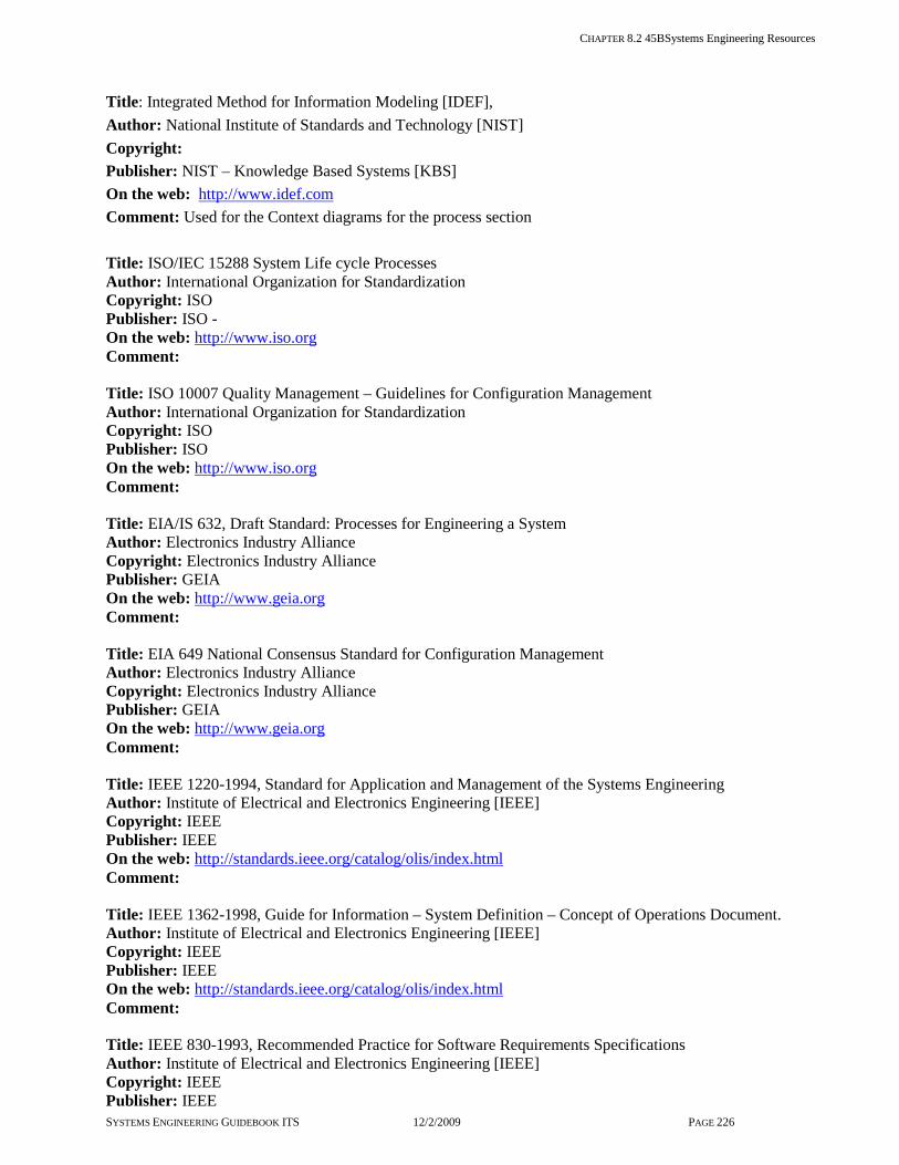
CHAPTER 8.2 45BSystems Engineering Resources
SYSTEMS ENGINEERING GUIDEBOOK ITS 12/2/2009 PAGE 226
Title: Integrated Method for Information Modeling [IDEF], Author: National Institute of Standards and Technology [NIST] Copyright: Publisher: NIST – Knowledge Based Systems [KBS] On the web: http://www.idef.com Comment: Used for the Context diagrams for the process section Title: ISO/IEC 15288 System Life cycle Processes Author: International Organization for Standardization Copyright: ISO Publisher: ISO - On the web: http://www.iso.org Comment: Title: ISO 10007 Quality Management – Guidelines for Configuration Management Author: International Organization for Standardization Copyright: ISO Publisher: ISO On the web: http://www.iso.org Comment: Title: EIA/IS 632, Draft Standard: Processes for Engineering a System Author: Electronics Industry Alliance Copyright: Electronics Industry Alliance Publisher: GEIA On the web: http://www.geia.org Comment: Title: EIA 649 National Consensus Standard for Configuration Management Author: Electronics Industry Alliance Copyright: Electronics Industry Alliance Publisher: GEIA On the web: http://www.geia.org Comment: Title: IEEE 1220-1994, Standard for Application and Management of the Systems Engineering Author: Institute of Electrical and Electronics Engineering [IEEE] Copyright: IEEE Publisher: IEEE On the web: http://standards.ieee.org/catalog/olis/index.html Comment: Title: IEEE 1362-1998, Guide for Information – System Definition – Concept of Operations Document. Author: Institute of Electrical and Electronics Engineering [IEEE] Copyright: IEEE Publisher: IEEE On the web: http://standards.ieee.org/catalog/olis/index.html Comment: Title: IEEE 830-1993, Recommended Practice for Software Requirements Specifications Author: Institute of Electrical and Electronics Engineering [IEEE] Copyright: IEEE Publisher: IEEE
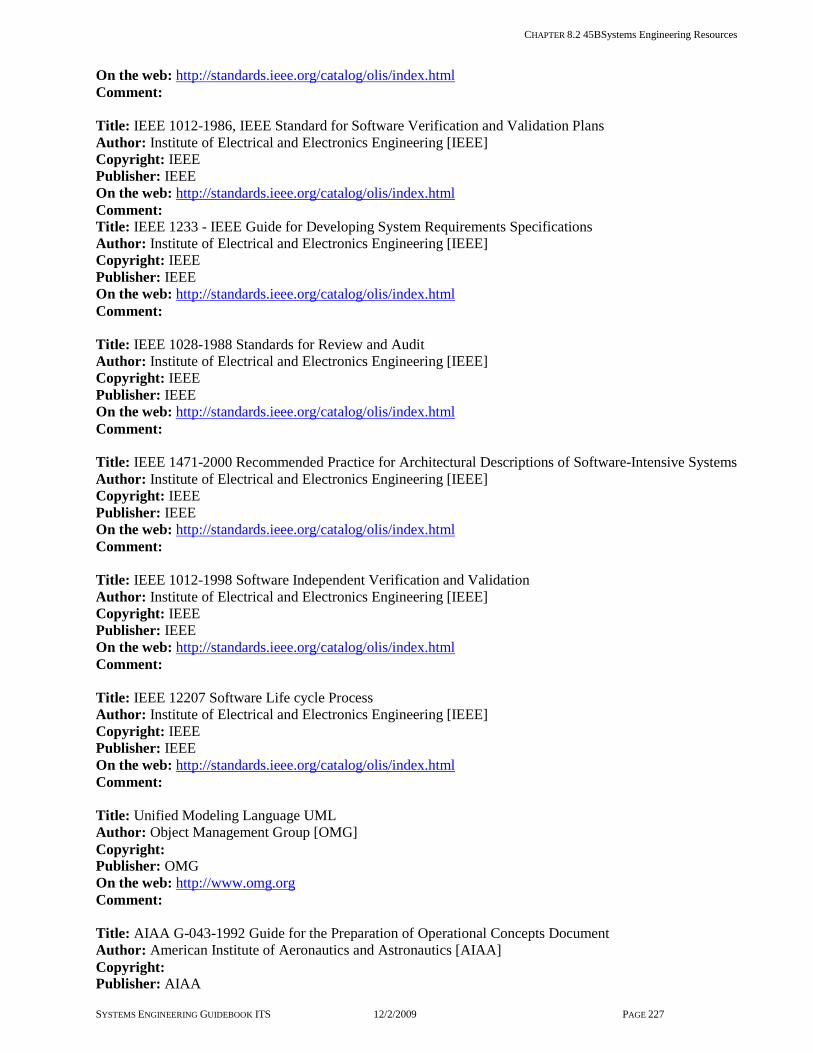
CHAPTER 8.2 45BSystems Engineering Resources
SYSTEMS ENGINEERING GUIDEBOOK ITS 12/2/2009 PAGE 227
On the web: http://standards.ieee.org/catalog/olis/index.html Comment: Title: IEEE 1012-1986, IEEE Standard for Software Verification and Validation Plans Author: Institute of Electrical and Electronics Engineering [IEEE] Copyright: IEEE Publisher: IEEE On the web: http://standards.ieee.org/catalog/olis/index.html Comment: Title: IEEE 1233 - IEEE Guide for Developing System Requirements Specifications Author: Institute of Electrical and Electronics Engineering [IEEE] Copyright: IEEE Publisher: IEEE On the web: http://standards.ieee.org/catalog/olis/index.html Comment: Title: IEEE 1028-1988 Standards for Review and Audit Author: Institute of Electrical and Electronics Engineering [IEEE] Copyright: IEEE Publisher: IEEE On the web: http://standards.ieee.org/catalog/olis/index.html Comment: Title: IEEE 1471-2000 Recommended Practice for Architectural Descriptions of Software-Intensive Systems Author: Institute of Electrical and Electronics Engineering [IEEE] Copyright: IEEE Publisher: IEEE On the web: http://standards.ieee.org/catalog/olis/index.html Comment: Title: IEEE 1012-1998 Software Independent Verification and Validation Author: Institute of Electrical and Electronics Engineering [IEEE] Copyright: IEEE Publisher: IEEE On the web: http://standards.ieee.org/catalog/olis/index.html Comment: Title: IEEE 12207 Software Life cycle Process Author: Institute of Electrical and Electronics Engineering [IEEE] Copyright: IEEE Publisher: IEEE On the web: http://standards.ieee.org/catalog/olis/index.html Comment: Title: Unified Modeling Language UML Author: Object Management Group [OMG] Copyright: Publisher: OMG On the web: http://www.omg.org Comment: Title: AIAA G-043-1992 Guide for the Preparation of Operational Concepts Document Author: American Institute of Aeronautics and Astronautics [AIAA] Copyright: Publisher: AIAA

CHAPTER 8.2 45BSystems Engineering Resources
SYSTEMS ENGINEERING GUIDEBOOK ITS 12/2/2009 PAGE 228
ISBN: http://www.aiaa.org/ Comment:
Military Standards and Handbooks
Title: Mil-Std-498 Software Documentation Author: Department of Defense Copyright: Publisher: DoD is not publishing this standard – search on the internet can download free ISBN: Comment: a number of useful Data Item Description document that provides outlines for various systems engineering documents Title: Mil-Hdbk-61 – Configuration Management Guidance Author: Department of Defense Copyright: Publisher: Search on the internet can download free ISBN: Comment: Excellent handbook on Configuration Management all phases Title: Mil Std-499C – System Engineering [Draft] Author: Department of Defense Copyright: Publisher: On the web: http://www.incose.org/newsevents/news/docs/499Cdraft_20050324.doc Comment: New effort on this standard. DoD last release of 499B was 1994 predecessor to EIA 632 8.2.4 References for Intelligent Transpor tation Systems and Transpor tation policies Title: Federal Final Rule [23 CFR 940 part 11] Author: FHWA Copyright: Publisher: On the web: http://www.access.gpo.gov/nara/cfr/waisidx_03/23cfr940_03.html Comment: Title: National ITS Architecture Author: FHWA Copyright: Publisher: DOT On the web: - http://www.its.dot.gov/arch/index.htm Comment: Title: Systems Engineering for ITS: An Introduction for Transportation Professionals Author: FHWA Copyright: Publisher: FHWA On the web: http://www.ops.fhwa.dot.gov/publications/seitsguide/index.htm Comment: This handbook provides an accessible introduction to SE concepts and makes a good companion to this Systems Engineering Guidebook. Title: A Guide to Configuration Management for Intelligent Transportation Systems Author: Federal Highway Administration Copyright: Publisher: FHWA On the web: http://www.itsdocs.fhwa.dot.gov/JPODOCS/REPTS_TE/13622.html
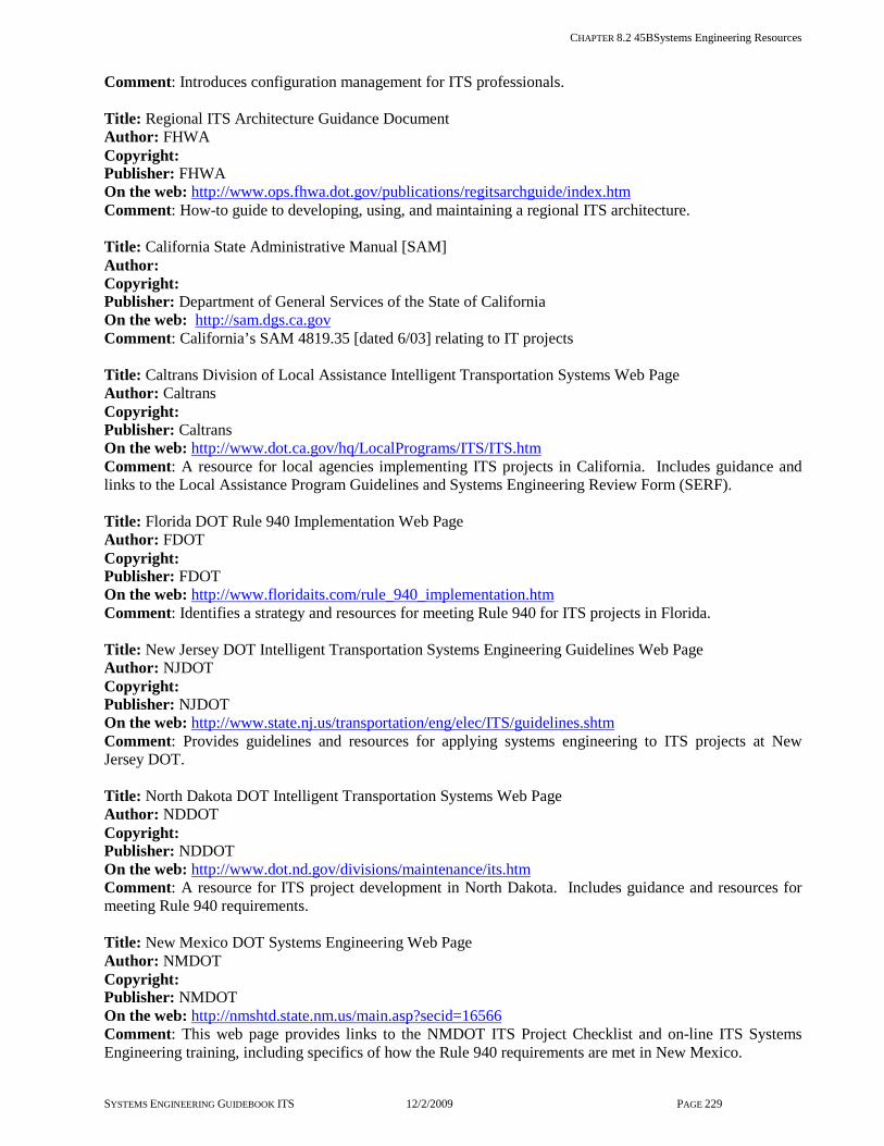
CHAPTER 8.2 45BSystems Engineering Resources
SYSTEMS ENGINEERING GUIDEBOOK ITS 12/2/2009 PAGE 229
Comment: Introduces configuration management for ITS professionals. Title: Regional ITS Architecture Guidance Document Author: FHWA Copyright: Publisher: FHWA On the web: http://www.ops.fhwa.dot.gov/publications/regitsarchguide/index.htm Comment: How-to guide to developing, using, and maintaining a regional ITS architecture. Title: California State Administrative Manual [SAM] Author: Copyright: Publisher: Department of General Services of the State of California On the web: http://sam.dgs.ca.gov Comment: California’s SAM 4819.35 [dated 6/03] relating to IT projects Title: Caltrans Division of Local Assistance Intelligent Transportation Systems Web Page Author: Caltrans Copyright: Publisher: Caltrans On the web: http://www.dot.ca.gov/hq/LocalPrograms/ITS/ITS.htm Comment: A resource for local agencies implementing ITS projects in California. Includes guidance and links to the Local Assistance Program Guidelines and Systems Engineering Review Form (SERF). Title: Florida DOT Rule 940 Implementation Web Page Author: FDOT Copyright: Publisher: FDOT On the web: http://www.floridaits.com/rule_940_implementation.htm Comment: Identifies a strategy and resources for meeting Rule 940 for ITS projects in Florida. Title: New Jersey DOT Intelligent Transportation Systems Engineering Guidelines Web Page Author: NJDOT Copyright: Publisher: NJDOT On the web: http://www.state.nj.us/transportation/eng/elec/ITS/guidelines.shtm Comment: Provides guidelines and resources for applying systems engineering to ITS projects at New Jersey DOT. Title: North Dakota DOT Intelligent Transportation Systems Web Page Author: NDDOT Copyright: Publisher: NDDOT On the web: http://www.dot.nd.gov/divisions/maintenance/its.htm Comment: A resource for ITS project development in North Dakota. Includes guidance and resources for meeting Rule 940 requirements. Title: New Mexico DOT Systems Engineering Web Page Author: NMDOT Copyright: Publisher: NMDOT On the web: http://nmshtd.state.nm.us/main.asp?secid=16566 Comment: This web page provides links to the NMDOT ITS Project Checklist and on-line ITS Systems Engineering training, including specifics of how the Rule 940 requirements are met in New Mexico.

CHAPTER 8.2 45BSystems Engineering Resources
SYSTEMS ENGINEERING GUIDEBOOK ITS 12/2/2009 PAGE 230
Title: Systems Engineering Evaluation for ITS Executive Summary Author: California Center for Innovative Transportation (CCIT) Copyright: Publisher: CCIT On the web: http://www.fhwa.dot.gov/cadiv/segb/files/caltransevalsumm.pdf Comment: This effort was a detailed CMMI-based evaluation of the systems engineering processes at Caltrans. Title: Systems Engineering Evaluation for ITS Final Report Author: California Center for Innovative Transportation (CCIT) Copyright: Publisher: CCIT On the web: http://www.fhwa.dot.gov/cadiv/segb/files/caltransevalreport.pdf Comment: This effort was a detailed CMMI-based evaluation of the systems engineering processes at Caltrans. Title: National Transportation Communications and Information Protocol [NTCIP] Family of Standards Author: AASHTO, ITE, NEMA Copyright: Publisher: AASHTO, ITE, NEMA On the web: http://www.ntcip.org Comment: 8.2.5 Systems Engineer ing Training A broad range of webinars, blended learning, workshops, and traditional courses are available to the ITS professional. In addition to the ITS-specific offerings identified here, many universities also offer systems engineering-related courses. Title: ITS Professional Capacity Building Program On the web: http://www.pcb.its.dot.gov Comment: The PCB sponsors the popular Talking Technology and Transportation (T3) webinars – interactive net meetings where ITS experts present a wide range of topics, including many related to systems engineering and project management. Title: Consortium for ITS Training and Education (CITE) On the web: http://citeconsortium.org Comment: The Consortium for ITS Training and Education (CITE) is a unique organization of universities and industry associations focused on providing comprehensive advanced transportation training and education that is flexible and convenient for its students. CITE offers over thirty interactive web-based courses for transportation technicians, professionals and college students. Title: Systems Engineering for ITS Workshop Author: Federal Highway Administration Comment: This two day workshop combines one day of training in systems engineering and a one day process improvement review where workshop participants review their own systems engineering processes. Contact your FHWA Division Office or Emiliano Lopez ([email protected]) for more information. 8.2.6 Systems Engineer ing Tools Title: INCOSE Systems Engineering Tools Database Author: International Council on Systems Engineering On the web: http://www.incose.org/ProductsPubs/products/toolsdatabase.aspx

CHAPTER 8.2 45BSystems Engineering Resources
SYSTEMS ENGINEERING GUIDEBOOK ITS 12/2/2009 PAGE 231
Comment: INCOSE maintains a comprehensive database of systems engineering tools with a comparison of features. This is a great resource to look at when considering software packages that support systems engineering.

CHAPTER 8.3 Contract Template Guidance
SYSTEMS ENGINEERING GUIDEBOOK ITS 12/2/2009 PAGE 232
8.3 Contract Template Guidance This chapter provides general guidance on two aspects of contracting, RFP, and the Intellectual Property Rights Clause. These are especially important and are somewhat unique for Intelligent Transportation Systems. However, it is critical to note that the general guidance contained here is not meant to supersede guidance from the agency. Project developers must always check with their agency’s contracting and procurement staff for specific and mandatory guidance on contracting issues.
Most aspects of contracting, or procurement, are the same across almost all categories of the transportation infrastructure. Indeed, some are common to almost any type of procurement. However, any development of a software-intensive ITS brings up a whole host of new considerations. These considerations stretch all the way from initial concept, through requirements, design, build, and verification. Since it is very common to contract with consultants and system developers for some of these efforts, some of these special considerations can reflect back into the contracting documents and processes themselves.
Although this Guidebook touches on procurement, it does so only as it relates to the systems engineering processes. Other documents, available from the Federal Highway Administration, will provide more information on the procurement options for ITS.
In this section, only two aspects of procurement are discussed. The first is guidance on the contents of an RFP package. The second is the need for an Intellectual Property Rights clause to give the procuring agency the rights it needs for follow-on maintenance and upgrades of software products.
This chapter contains guidance on the following topics:
RFP Intellectual Property Rights Clause 8.3.1 Request for Proposal Template Preparation of a RFP [Request for Proposal], is very common when developing an Intelligent Transportation System. This chapter discuses the technical and project management aspects of an RFP. It does not cover, with the exception of the following chapter on Intellectual Property Rights,
contractual or legal issues related to procurement. Procurement options are covered in Chapter 4.9.
The primary purpose of an RFP is to tell prospective contractors what is needed. It is always good to remember,” If it is not asked for, it probably will not be provided”. This is especially true when the procurement is going to be cost competitive. Here, a contractor is going to be penalized if they provide something needed that wasn't specifically asked for. This also will cause difficulty in justifying a higher price. On the other hand, if the RFP is too specific the contractor may be discouraged from bidding a lower cost solution which is perfectly adequate.
Following is a list, and description, of the most commonly found parts of a good RFP. Not all of these parts may be required every time and for every type of procurement.
SOW [Statement of Work] The Statement of Work tells the potential contractor what tasks are to be performed. The SOW is like the Project Plan discussed in sections 3.4.1 - Project Planning, and 7.5.1 - Project Plan Template. It always contains a high level description of the project to give the prospective contractors a sense of the context of their work. It is generally written by breaking down the work to be done into a number of individual tasks. Then, each task is described by its inputs, approach, and outputs. The inputs are the information needed by the contractor to do the task. The approach is guidance on how the task is to be done [for instance, specific trade-off studies may be required]. The outputs are the products of the task, such as: documents, meetings, and deliverable hardware and software. It is important to describe the contents of any required documents. Chapter 8.4 of this Guidebook gives descriptions of some of the most common documents that could be required. All tasks, including administrative tasks, need to be included in the Statement of Work.
Technical Specifications One or more technical specifications may be required to describe the products to be procured. If the product is COTS, a part number or model number is all that is necessary. If the product is to be developed, then a requirements specification is needed. Chapter 8.4.6 provides templates for a requirements specification.
Sometimes the requirement specifications are planned to be written as part of the contractor’s
SECTION 8.3 CONTRACT TEMPLATE GUIDANCE
SYSTEMS ENGINEERING GUIDEBOOK ITS 12/2/2009 PAGE 233
effort. In this case, some level of a description of the intended product is still needed and this must be prepared before the RFP is released.
Schedule The RFP must contain a schedule for the tasks. This schedule should be at as high a level as possible. It should only contain dates that must be met by the contractor. Examples include: a start date, a delivery date[s], or a date after which an important external system is available. Let the contractor propose internal dates, such as: delivery of a specification, delivery of design documents, and start of verification. In fact, the contractor should propose a schedule for every deliverable of every task.
List of Deliverables It is good practice to compile a comprehensive list of all deliverables, including documents, products, and meetings. This identifies, in one location, all of the deliverables needed to complete each task of the project. All deliverables are referenced to the task that produces them. They are also listed as outputs of that task. Documents are referenced to the document descriptions and products are referenced to the appropriate specification, if any. This list includes information about quantities. It also includes ground rules for agency review & comment ,and for incorporation of comments.
Contract Terms and Conditions Contract terms and conditions are generally provided by the agency’s procurement or purchasing departments. Much of these contract terms are standardized and apply to any procurement. However, some will be specialized to a specific type of contract or procurement. It is important that they are compared to other parts of the RFP package to avoid conflicts.
Format of Proposal The RFP needs to tell prospective bidders what their response should look like. Generally, this is in terms of both form and content. Quite often, for instance, a page limit is placed on their response. This helps them keep their focus on the items the agency wants to see. The main purpose of specifying the format and content of the response is to make it easier to compare bids from different contractors, and to ensure enough information is available to make that comparison.
A typical proposal may be asked to include:
Certifications by the contractor. For instance, certification of a clean record with other
agencies or certification of meeting a Disadvantaged Business Enterprise requirement
Demonstration of compliance with the RFP, including a complete list of any areas of known non-compliance. However, optional responses, for instance, a non-compliant, but lower cost way of meeting a requirement, may be allowed
A preliminary Project Plan, perhaps providing some detail on their approach to be used for each task. This part of the response is critical in determining and evaluating the contractor’s understanding of the project
A preliminary system design Qualification and Experience It is always necessary to obtain information about the qualifications and experience of the contractor and the key employees. This provides an indication that the contractor can perform the work requested. The demonstration of experience should include a list of comparable projects completed and references to the procuring agency. Qualification of employees is often provided in tailored resumes.
Cost Breakdown Quite often, the RFP requests that all cost data be submitted separately from the rest of the response. This is done so that the technical evaluation of the proposal is not tainted by knowledge of the cost of the proposal.
The cost figures are generally requested to be broken down in several different ways. Typically, costs are broken down by task. Within a task, the breakdown between labor costs and other direct costs [itemized] are shown. Labor is also shown by hours and by labor category [e.g. senior engineer, junior engineer].
Sometimes, a breakdown of the total cost is requested to show labor costs, direct costs, overhead, and fees.
RFP Evaluation Criteria Evaluation related guidance is given to the contractors in preparation for completing the RFP. It is rare when an ITS proposal is evaluated by cost alone. Generally technical, management, experience, and qualifications are given equal, if not a higher, weighting. The purpose of this part of the RFP is to show contractors exactly what factors [based on information contained in their responses] will be evaluated and what relative weights will be given to each.

SECTION 8.3 CONTRACT TEMPLATE GUIDANCE
SYSTEMS ENGINEERING GUIDEBOOK ITS 12/2/2009 PAGE 234
8.3.2 Intellectual Proper ty Rights Template
One of the most challenging contractual problems associated with ITS is the establishment of adequate rights for the agency with respect to the system’s software. It has not been unusual for agencies to pay for the development of some custom transportation software programs only to find, because of restrictive contract language, they cannot see the code. The agency also may find they must go back to the original developer for maintenance and future system upgrades.
The rights of the agency to use a software product are established in an Intellectual Property Rights clause. It is included in the terms and conditions of their contract with the software developer. There are three aspects to these rights that are generally covered in this clause. The first is the agency’s right to receive from the developer not only the executable code, but also the source code and the related documentation needed to understand and replicate that code. The second is the agency’s right to use the code and the documentation to maintain and upgrade the software program. This includes the right to give the software and documentation to another development contractor for maintenance and/or upgrade. The third is the necessity to recognize that the original developer has some rights to the software as well. This is especially true if they, and not the agency, paid for the development of it.
To illustrate these points, example wording for the parts of an Intellectual Property Right clause is derived from wording developed by the Department of General Services of the State of California. This example is not intended to be used in a contract as an Intellectual Property Rights clause. A project manager should contact his agency’s legal staff for appropriate contract wording.
Issue 1 – Getting the Necessary Documentation This is really a problem for the Contract’s Statement of Work. The Statement of Work is where the deliverable documents and products are defined. It is where the delivery of executable and source code, as well as other related documents, is defined. Related documents may include High Level and Detailed Design Specifications, Software Development Plans, instructions on how to compile the executable code, and user’s manuals. A sample clause for the contract is:
DOCUMENTATION The Contractor agrees to provide to the Agency a number of all nonproprietary manuals and other printed material, as described with the Statement of Work, and updated versions thereof, which are necessary or useful to the Agency in its use of the Equipment or Software provided hereunder.
Issue 2 – Getting the Right to Use the Software and Related Documentation
This part of the Intellectual Property Rights puzzle is handled entirely in the Contract. Here the agency wants to get and retain the unencumbered rights to:
Use the software in the system it was designed for
Give the software and documents to a third party [another contractor] for maintenance and upgrades
Give the software and related documents to another government agency for their use
The example clause does this by defining a set of “Government Purpose Rights” which it then gives to the agency. In doing this, it also defines rights which are left as the sole or joint right of the development contractor.
A sample clause for the contract is:
RIGHTS IN WORK PRODUCTS 1. All inventions, discoveries, intellectual
property, technical communications, and records originated or prepared by the Contractor pursuant to this Contract including papers, reports, charts, computer programs, and other Documentation of improvements thereto, and including Contractor’s administrative communications and records related to this Contract [collectively, the “Work Product”], shall be Contractor’s exclusive property. The provisions of this sub-section may be revised in a Statement of Work.
2. Software and other materials developed or otherwise obtained by or for Contractor or its affiliates independently of this Contract or applicable purchase order [“Pre-Existing Materials”] do not constitute Work Product. If Contractor creates derivative works of Pre-Existing Materials, the elements of such derivative works created pursuant to this Contract

SECTION 8.3 CONTRACT TEMPLATE GUIDANCE
SYSTEMS ENGINEERING GUIDEBOOK ITS 12/2/2009 PAGE 235
constitute Work Products, but other elements do not. Nothing in this Chapter will be construed to interfere with Contractor’s or its affiliates’ ownership of Pre-Existing Materials.
3. The Agency will have Government Purpose Rights to the Work Product as Deliverable or delivered to the Agency hereunder. “Government Purpose Rights” are the unlimited, irrevocable, worldwide, perpetual, royalty-free, non-exclusive rights and licenses to use, modify, reproduce, perform release, display, create derivative works from, and disclose the Work Product. “Government Purpose Rights” also include the right to release or disclose the Work Product outside the Agency for any Agency purpose and to authorize recipients to use, modify, reproduce, perform, release, display, create derivative works from, and disclose the Work Product for any Agency purpose. Such recipients of the Work Product may include, without limitation, Agency Contractors or other agencies. “Government Purpose Rights” do not include any rights to use, modify, reproduce, perform, release, display, create derivative works from, or disclose the Work Product for any commercial purpose.
4. The ideas, concepts, know-how, or techniques relating to data processing, developed during the course of this Contract by the Contractor or jointly by the Contractor and the Agency, may be used by either party without obligation of notice or accounting.
5. This Contract shall not preclude the Contractor from developing materials outside this Contract .which are competitive, irrespective of their similarity to materials which might be delivered to the Agency pursuant to this Contract.
Issue 3 – Agreeing to the Rights of the Development Contractor
The third and final issue that the Intellectual Property Rights clause must deal with is recognizing rights retained by the developer. Not all of the software components the developer uses in the system software were developed just for this project. Sometimes, the developer uses software that they have developed, at their own
expense, as a product line. Because the agency does not pay their development costs, they cannot expect to get the same all-inclusive rights as they would get to custom software. In addition, many components of the software, such as the operating system, a database engine, or communications packages, have been developed by third parties. Since the developer’s business livelihood is dependent on the exclusive ownership of those products, the agency not only gets limited rights, but also must take reasonable steps to protect what information they do get from the original developer’s competitors.
A sample clause for the contract is:
PROTECTION OF PROPRIETARY SOFTWARE AND OTHER PROPRIETARY DATA
1. Agency agrees that all material appropriately marked or identified in writing as proprietary, and furnished hereunder are provided for Agency’s exclusive use for the purposes of this Contract only. All such proprietary data shall remain the property of the Contractor. Agency agrees to take all reasonable steps to insure that such proprietary data are not disclosed to others, without prior written consent of the Contractor, subject to law.
2. The Agency will insure, prior to disposing of any media, that any licensed material contained thereon have been erased or otherwise destroyed.
3. The Agency agrees that it will take appropriate action by instruction, agreement, or otherwise with its employees or other persons permitted access to licensed software and other proprietary data to satisfy its obligations under this Contract with respect to use, copying, modification, protection, and security of proprietary software and other proprietary
data. Use of software escrow accounts is one approach that allows the contractor to maintain rights and
also protects the buyer. A Software escrow account is a specialized firm that holds intellectual property such as source code and design documentation in case the contractor defaults, or goes bankrupt. Then, it is released to the buyer.
SECTION 8.4 SYSTEMS ENGINEERING DOCUMENTATION TEMPLATE GUIDANCE
SYSTEMS ENGINEERING GUIDEBOOK ITS 12/2/2009 PAGE 236
8.4 Systems Engineer ing Documentation Template Guidance This chapter provides guidance on the preparation of some of the most commonly used systems engineering documents. This guidance is in the form of a preliminary discussion of: the purpose of the document, suggestions on tailoring the document to the project, and a checklist of critical information to be included. This is followed by a suggested document outline showing and explaining each major part or chapter of the document.
Each document is referenced back to its process in Chapter 3. For best effect, the process sections and the document guidance sections should be studied together.
Guidance is provided on the following systems engineering documents: Project Plan [see Ch. 3.4.1] Systems Engineering Management Plan [see
process Ch.3.4.2, Systems Engineering Management Planning]
Configuration Management Plan [see process Chapter 3.9.6, Configuration Management / Interface Management]
Needs Assessment [see process Ch. 3.3.1, Needs Assessment]
Concept of Operations [see process Ch. 3.4.3, Concept of Operations]
Requirements Specification [see process Ch. 3.5.1, Requirements Development]
Design Specifications [see process Ch. 3.5.2, High Level Design and 3.5.3, Component Detailed Design]
Integration Plan [see process Ch. 3.6.2, Integration]
Verification Documents [see process Ch. 3.6.3, Verification]
Deployment Plan [see process Ch. 3.6.4 Initial System Deployment]
Operations & Maintenance Plan [see process Ch. 3.7.2, Operations & Maintenance]

SECTION 8.4 SYSTEMS ENGINEERING DOCUMENTATION TEMPLATE GUIDANCE
SYSTEMS ENGINEERING GUIDEBOOK ITS 12/2/2009 PAGE 237
8.4.1 Project Plan Template Purpose of this Document The Project Plan is the governing document for the conduct of a project. All other plans and technical documents follow from the Project Plan. Most agencies have project management procedures which call for the creation of a Project Plan. Obviously, those need to be followed. The Project Plan described here shows the most commonly needed elements of a Project Plan.
The purpose of the Project Plan is to define and describe all of the tasks that need to be performed to accomplish the project. Each task is described in enough detail that the assigned personnel can do it satisfactorily. It is also critical that the products of each task, the schedule for each task, and the available budget are established. Further, the assigned personnel need to “buy-in” to this plan and believe they can do their task on time and within budget.
Also, the Project Plan establishes and identifies the environment in which the project will operate. It identifies all the players in the project including management, responsible teams or organizations for each task, supporting organizations, and all stakeholders.
Tailoring This Document to Your Project Although almost always required, the size of the Project Plan can vary considerably depending on the complexity of the project and the breadth of its environment. If needed, the Project Plan can be supplemented with a variety of supporting plans. Depending on complexity, it may be more efficient to document all this support plan information in the Project Plan itself.
The more expensive a project, the more that management will want to see that it is well planned.
The technical complexity of a project translates directly into technical risk that must be managed through good planning. The stakeholders will use the Project Plan to understand and plan their roles and it provides a means for them to review and comment on their ability to perform the needed tasks. Checklist: Critical Information Are all of the necessary tasks included in the
plan [perhaps in the form or a Work Breakdown Structure] along with identification of the personnel or team that is responsible for performing the task?
Is the sequence of the tasks correct so that the necessary precursor work is done for each task?
Is the budget assigned to each task sufficient to get the task done as defined? Does the team that will perform the task agree?
Is the scheduled time period for each task sufficient to get the work done as defined? Does the team that will perform the task agree?
Are the necessary stakeholder organizations identified? Are their roles defined and agreed to?
Are all products of each task [documents, meetings, hardware and software] identified? Or, alternatively, is a task defined to identify those products?
Are any supporting plans required to supplement the Project Plan? Is their preparation defined as a task?
Do all stakeholders, including management, approve the Project Plan?

SECTION 8.4 SYSTEMS ENGINEERING DOCUMENTATION TEMPLATE GUIDANCE
SYSTEMS ENGINEERING GUIDEBOOK ITS 12/2/2009 PAGE 238
PROJECT PLAN TEMPLATE SECTION CONTENTS
Title Page The title page should follow the Transportation Agency procedures or style guide. At a minimum, it should contain the following information: PROJECT PLAN FOR THE [insert name of project] AND [insert name
of transportation agency] Contract number Date that the document was formally approved The organization responsible for preparing the document Internal document control number, if available Revision version and date issued
1.0 Purpose of Document
The purpose of this document is the plan for execution of the project including defining all necessary tasks and their products.
2.0 Scope of Project
This section provides a brief description of the planned project and the purpose of the system to be built. Special emphasis is placed on the project’s complexities and challenges to be addressed by the project’s managers. This section defines the project’s relationship to the applicable regional ITS architectures and, if necessary, to the National ITS Architecture. It also defines the relationship of the project’s system to other systems with which it interfaces, either physically [with a data interface] or operationally. This section describes the environment in which the project will operate. It identifies the organizational structures that encompass all stakeholders and gives a brief description of the role to be played by each stakeholder. This section identifies organizations within the owning agency that are stakeholders in this project. It also identifies any external agencies [especially agencies with a system that interfaces with this project’s system] that are project stakeholders. A subsequent project management task is to identify individuals within those organizations and agencies who will represent their organization among the project’s stakeholders. It is especially important that the Project Plan identify the system’s owners who are building the system and the customer for whom the system is being built. The section also identifies any existing management work groups and multi-disciplinary technical teams to be used to support the project.
3.0 Project Tasks
This section is the heart of the Project Plan. It defines each task of the project in terms of its inputs, approach, and outputs. Inputs: Identification of the inputs to each task. Inputs can be a variety of things, including, but certainly not limited to: Documents from outside the project or from other tasks of the project,
that are meant to guide the activities of this task, such as, a regional ITS architecture and other planning documents
Directions from others that guide the efforts of the team performing this task, such as directions from a multi-agency steering committee established for this project
Meetings with others to be conducted by the team performing this task, such as periodic status meetings with the project manager’s organizational management.
Products, other than documents, from other tasks that are a necessary precursor to the performance of this task. For example, a product from an integration task is a software and hardware component that is a necessary

SECTION 8.4 SYSTEMS ENGINEERING DOCUMENTATION TEMPLATE GUIDANCE
SYSTEMS ENGINEERING GUIDEBOOK ITS 12/2/2009 PAGE 239
SECTION CONTENTS input to a verification task.
Approach: A description of the approach to be taken by the team performing the task. This may include: a description of the products of the task; the analysis sub-tasks to be undertaken; or even a breakdown of the tasks into sub-tasks. This description may include identification of procurement activities that need to be taken in this task. For systems engineering and design tasks, this description may be expanded as necessary in the Systems Engineering Management Plan, which, of course, would be an activity and output of one of the tasks. Outputs: A description of the products of the task. As with inputs, the outputs may take many forms, including, but not limited to: Documents to be produced by the task team, such as, specifications,
Verifications Plans, and the SEMP. Meetings, including management meetings and technical reviews Other products such as software code, procured hardware, and integrated
or verified sub-systems Attendance at meetings conducted by others, such as periodic meetings
of a multi-agency steering committee 4.0 Work Breakdown Structure and Task Budgets
This section provides a hierarchical structure of all tasks and sub-tasks of the project, identifying the name of the task or sub-task, the allocated budget, and the team or organization with the authorization and responsibility to perform the task. The budget may not be allocated to each sub-task but may be allocated to a higher level group of sub-tasks, tasks, or group of tasks, as necessary to manage the project.
5.0 Schedule Constraints
A project’s schedule is developed in two steps, and this section, at a minimum, includes information to define the initial step of schedule development. The two steps in development of a project’s schedule are: Step one: identification of external schedule constraints. These may
include a not-earlier-than start date, a not-later-than completion date, a date tied to the completion of an external system, or the date a needed resource is available. In general, these schedule constraints come from outside the project and are not within the control of the project’s management.
Step Two: development of a schedule for each task, for each sub-task, and for each output of a task. This schedule is under complete control of the project’s management by a variety of means, including the assignment of more or fewer resources. This schedule takes into account the necessary precursors [inputs] to each task or sub-task.
The schedule in this section of the Project Plan includes the output of step one and may either include the complete schedule of step two or identify this as an output of one of the tasks.
6.0 Deliverable Requirements List
This section is, as much as possible, a complete and precise list of the tangible deliverables of each and every task. In general, a tangible deliverable may include, from the list of outputs of a task: Documents, especially documents to be reviewed by stakeholders, and
documents to be used after the system is built Meetings and reviews to be attended by project stakeholders Other products, such as deliverable hardware [by name, part number, and
quantity] and deliverable software products, such as source code and

SECTION 8.4 SYSTEMS ENGINEERING DOCUMENTATION TEMPLATE GUIDANCE
SYSTEMS ENGINEERING GUIDEBOOK ITS 12/2/2009 PAGE 240
SECTION CONTENTS executables
It may not be possible to completely and precisely define each and every deliverable at the time the Project Plan is prepared. For instance, the Project Plan may state that design specifications are required but the identification of specific documents may have to wait until the sub-systems are defined in the high level design task.
7.0 Referenced Documents
This section lists the applicable documents that are inputs to the project [that is, are needed by but not produced by the project]. Such documents may include: the regional ITS architecture description, planning documents describing the project, agency procedures to be followed, standards, specifications, and other descriptions of interfacing external systems. Other applicable documents may be required by a specific project.
SECTION 8.4 SYSTEMS ENGINEERING DOCUMENTATION TEMPLATE GUIDANCE
SYSTEMS ENGINEERING GUIDEBOOK ITS 12/2/2009 PAGE 241
8.4.2 Systems Engineer ing Management Plan Template
Purpose of this Document The SEMP [Systems Engineering Management Plan], may be needed to supplement the details of the Project Plan. When used, the SEMP focuses on the technical plan of the project and the systems engineering processes to be used for the project. Its purpose is to detail out those engineering tasks; especially to provide detailed information on the processes to be used. Preparation of a SEMP is most important if the project involves development of custom software. The engineering tasks of producing custom software [from requirements, through design implementation, integration, and verification] are very complex, and are new to many transportation engineers. Given the level of process detail needed in the SEMP, it often written in two steps. In the first step, the framework for the document is prepared, usually by the project management staff. Enough detail is included to identify all the needed tasks [including analysis tasks] and any important constraints on the performance of a task [such as use of a specific systems engineering and design methodology]. In the second step, the various sections of the SEMP framework are completed, this time by the team that will perform each task. For instance, the requirements team provides details on the analysis and the tools used to manage requirements. The design team provides details on use of the software design methodology. The software coder provides details on configuration management of the software code. The verification team provides details on their verification methods. These SEMP template were adapted from guidelines prepared by the Caltrans Office of Local Assistance. See the web page at: http://www.dot.ca.gov/hq/LocalPrograms/lam/prog_g/g12othr.pdf .
Tailoring this Document to Your Project The simplest ITS projects may not need a SEMP; the Project Plan may be sufficient. Among the project complexities that make preparation of a SEMP desirable are: Inexperience of the system’s owner’s project
team in the systems engineering tasks and processes
A larger number of stakeholders and the degree of their involvement in the various systems engineering processes and tasks
The need to develop custom software applications
A project where the solution is not well understood and is not generally obvious
Checklist: Critical Information Are all the technical challenges of the project
addressed by the systems engineering processes described in the SEMP?
Does the SEMP describe the processes needed for requirements analysis?
Does the SEMP describe the design processes and the design analysis steps required for an optimum design?
Does the SEMP clearly identify any necessary supporting technical plans, such as a Verification Plan or an Integration Plan? Does it define when and how they will be written?
Does the SEMP spell out stakeholder involvement when it is necessary?
Does the SEMP identify all the required technical staff and development teams? Does it identify the technical roles to be performed by the system’s owner, project staff, stakeholders, and the development teams?
Does the SEMP cover the interfaces between the various development teams?

CHAPTER 8.4.2 SYSTEMS ENGINEERING MANAGEMENT PLAN TEMPLATE
SYSTEMS ENGINEERING GUIDEBOOK ITS 12/2/2009 PAGE 242
SYSTEMS ENGINEERING MANAGEMENT PLAN TEMPLATE SECTION CONTENTS
Title Page The title page should follow the Transportation Agency procedures or style guide. At a minimum, it should contain the following information: SYSTEMS ENGINEERING MANAGEMENT PLAN FOR THE [insert
name of project] AND [insert name of transportation agency] Contract number Date the the document was formally approved The organization responsible for preparing the document Internal document control number, if available Revision version and date issued
1.0 Purpose of Document
This section is a brief statement of the purpose of this document and the plan for the systems engineering activities with special emphasis on the engineering challenges of the system to be built.
2.0 Scope of Project
This section gives a brief description of the planned project and the purpose of the system to be built. Special emphasis is placed on the project’s complexities and challenges that must be addressed by the systems engineering efforts. This section also describes the environment in which the project will operate. It identifies the organization structures that encompass all stakeholders. It gives a brief description of the role to be played by each stakeholder. This includes ad hoc and existing management work groups and multi-disciplinary technical teams that should be formed or used to support the project. Such teams are critical to reaching successful system deployment. This section defines the general process for developing the SEMP, including the draft framework version prepared by the transportation agency or their Systems Engineer and the complete version prepared in conjunction with the Systems Engineer and Development Teams.
3.0 Technical Planning and Control
This section lays out the plan for the systems engineering activities. It must be written in close synchronization with the project’s Project Plan. Unnecessary duplication between the Project Plan and the SEMP should be avoided. However, it is often necessary to put further expansion of the systems engineering effort into the SEMP even if they are already described at a higher level in the Project Plan. Even within the SEMP, an effort may need to be described at a higher level in the draft SEMP framework. Then it may need to be expanded further in the final version of the SEMP. An example would be the Configuration Management Plan, to be described below. The purpose of the section is to describe the activities and plans that will act as controls on the project’s systems engineering activities. For instance, this section identifies the products of each systems engineering activity, such as, documentation, meetings, and reviews. This list of required products will control the activities of the team performing the activity and will control the satisfactory completion of the activity. Some of these plans may be completely defined in the SEMP [in the framework or the complete version]. For other plans, the SEMP may only define the requirements for a particular plan. The plan itself is to be prepared as one of the subsequent systems engineering activities, such as may be the case with a Verification Plan or a Deployment Plan. Almost any of the plans described below may fall into either category. It all depends on the complexity of the particular plan and

CHAPTER 8.4.2 SYSTEMS ENGINEERING MANAGEMENT PLAN TEMPLATE
SYSTEMS ENGINEERING GUIDEBOOK ITS 12/2/2009 PAGE 243
SECTION CONTENTS the amount of up-front systems engineering that can be done at the time the SEMP is prepared. The first set of required activities/plans relates primarily to the successful management of the project. These activities are likely to have already been included in the Project Plan, but may need to be expanded here in the SEMP. Generally, they are incorporated into the SEMP; but, on occasion, may be developed as separate documents. Work Breakdown Structure [WBS] [also included in the Project Plan]
a list of all tasks to be performed on a project, usually broken down to the level of individually budgeted items
Task Inputs is a list of all inputs required for each task in the WBS, such as source requirements documents, interface descriptions, and standards.
Task Deliverables is a list of the required products of each task in the WBS, including documents, software, and hardware
Task Decision Gates is a list of critical activities that must be satisfactorily completed before a task is considered completed
Reviews and Meetings is a list of all meetings and reviews of each task in the WBS
Task Resources is identification of resources needed for each task in the WBS, including for example, personnel, facilities, and support equipment
Task Procurement Plan is a list of the procurement activities associated with each task of the WBS, including hardware and software procurement and, most importantly, any contracted services, such as systems engineering services or development services
Critical Technical Objectives is a summary of the plans for achieving any critical technical objectives that may require special systems engineering activities. It may be that a new software algorithm needs to be developed and its performance verified before it can be used. Or a prototyping effort is needed to develop a user-friendly operator interface. Or a number of real-time operating systems need to be evaluated before a procurement selection is made. This type of effort is not needed for all projects
Systems Engineering Schedule a schedule of the systems engineering activities that shows the sequencing and duration of these activities. The schedule should show tasks [at least to the level of the WBS], deliverable products, important meetings & reviews, and other details needed to control and direct the project. An important management tool is the schedule. It is used to measure the progress of the various teams working on the project and to highlight work areas that need management intervention
The second set of plans is designed to address specific areas of the systems engineering activities. They may be included entirely in the SEMP or the SEMP may give guidance for their preparation as separate documents. The plans included in the first set listed above are generally universally applicable to any project. On the other hand, some of the plans included in this second set are only rarely required. The unique characteristics of a project will dictate their need. Software Development Plan describes the organization structure,
facilities, tools, and processes to be used to produce the project’s software. Describes the plan to produce custom software and procure

CHAPTER 8.4.2 SYSTEMS ENGINEERING MANAGEMENT PLAN TEMPLATE
SYSTEMS ENGINEERING GUIDEBOOK ITS 12/2/2009 PAGE 244
SECTION CONTENTS commercial software products
Hardware Development Plan describes the organization structure, facilities, tools, and processes to be used to produce the project’s hardware. It describes the plan to produce custom hardware [if any] and to procure commercial hardware products
Technology Plan if needed, describes the technical and management process to apply new or untried technology to an ITS use. Generally, it addresses performance criteria, assessment of multiple technology solutions, and fall-back options to existing technology
Interface Control Plan identifies the physical, functional, and content characteristics of external interfaces to a system and identifies the responsibilities of the organizations on both sides of the interface
Technical Review Plan identifies the purpose, timing, place, presenters & attendees, subject, entrance criteria, [a draft specification completed] and the exit criteria [resolution of all action items] for each technical review to be held for the project
System Integration Plan defines the sequence of activities that will integrate software components into sub-systems and sub-system into entire systems. This plan is especially important if there are many sub-systems produced by a different development team
Verification Plan almost always required, this plan is written along with the requirements specifications. However, the parts on test conduct can be written earlier
Verification Procedures are developed by the Development Team and this defines the step by step procedure to conduct verification and must be traceable to the verification plan
Installation Plan or Deployment Plan describes the sequence in which the parts of the system are installed [deployed]. This plan is especially important if there are multiple different installations at multiple sites. A critical part of the deployment strategy is to create and maintain a viable operational capability at each site as the deployment progresses
Operations & Maintenance Plan defines the actions to be taken to ensure that the system remains operational for its expected lifetime. It defines the maintenance organization and the role of each participant. This plan must cover both hardware and software maintenance
Training Plan describes the training to be provided for both maintenance and operation
Configuration Management Plan describes the development team’s approach and methods to manage the configuration of the system’s products and processes. It will also describe the change control procedures and management of the system’s baselines as they evolve
Data Management Plan describes how and which data will be controlled, the methods of documentation, and where the responsibilities for these processes reside
Risk Management Plan addresses the processes for identifying, assessing, mitigating, and monitoring the risks expected or encountered during a project’s life cycle. It identifies the roles & responsibilities of all participating organizations for risk management
Other plans that might be included are for example, a Safety Plan, a Security Plan, a Resource Management Plan, and/or a Validation Plan

CHAPTER 8.4.2 SYSTEMS ENGINEERING MANAGEMENT PLAN TEMPLATE
SYSTEMS ENGINEERING GUIDEBOOK ITS 12/2/2009 PAGE 245
SECTION CONTENTS This second list is extensive and by no means exhaustive. These plans should be prepared when they are clearly needed. In general, the need for these plans become more important as the number of stakeholders involved in the project increases.
4.0 Systems Engineering Process
This section describes the intended execution of the systems engineering processes used to develop the system. These processes are generically described in the Guidebook and identified in the VEE life cycle technical development model. The SEMP describes the processes specifically needed for a project. It defines them in sufficient detail to guide the work of the systems engineering and development teams. The FHWA’s Final Rule [23 CFR Part 940 part 11] places requirements on the minimum description of the systems engineering analysis for projects funded with highway trust funds. For all projects, the following factors should be discussed in the SEMP: Identification of portions of the regional ITS architecture being
implemented. Or, if a regional ITS architecture does not exist, the applicable portions of the National ITS Architecture
Identification of participating agencies and their roles & responsibilities Requirements definitions Analysis of alternative system configurations and technology options to
meet requirements Procurement options Identification of applicable ITS standards and testing procedures Procedures and resources necessary for operations & maintenance of the
system This section will contain a description of the systems engineering procedures tailored to the specific project. There are four areas of analysis that need to be described: System Requirements Analysis describes the methods to be used to
prepare the Concept of Operations and the top-level system requirements documents. The analysis techniques that may be used include: peer reviews, working groups, scenario studies, simulation, and prototyping. The amount of analysis required increases with the risk of the specific requirement. The process for approving the resulting documents will be described, including who is involved, whether technical reviews are necessary, and how issues and comments are resolved so the baseline can be defined
Sub-system [Functional] Analysis describes the methods to be used to identify sub-systems and to allocate the system [top-level] requirements to the sub-systems. It is often necessary, at this step, to expand the top-level requirements into a complete description of the functions of the system, for instance, details of an operator interface. It also may be necessary, at this time, to define internal interfaces [sub-system to sub-system] to the same level of detail as the external interfaces [interfaces to other systems]. The SEMP should describe the methods for analysis and the tools required. Budget and schedule constraints, as well as completion criteria, should be included
Design Synthesis describes the methods to be used by the development teams to translate the functional requirements into a hardware and software design. A number of tools and methodologies exist for this. The specific ones to be used by the development team should be identified,

CHAPTER 8.4.2 SYSTEMS ENGINEERING MANAGEMENT PLAN TEMPLATE
SYSTEMS ENGINEERING GUIDEBOOK ITS 12/2/2009 PAGE 246
SECTION CONTENTS along with the necessary resources. Describe the products to be produced as this process unfolds and the design review steps to be taken
System Analysis describes the methods to be used for any required technical trade-off studies, cost/benefit decisions, and risk mitigation alternative analysis. The methodologies used should provide a rigorous basis for selecting an alternative, a quantifiable basis for comparing the technical, cost, and schedule impacts of each alternative, and comprehensive description of the risks involved with each alternative.
5.0 Transitioning Critical Technologies
This section will describe the methods and processes to be used to identify, evaluate, select, and incorporate critical technologies into the system design. Since this may represent an area of considerable impact to the project, this is one of the major efforts of risk management. The need for a critical technology may be based on a performance objective. It may also be based on other factors; the desire to reduce acquisition or maintenance costs; the need to introduce standard compliance; or the need to meet an operational objective. In some cases, the need may move away from a technology that is obsolete and no longer supported by industry. Identification of candidate technologies hinges on a broad knowledge of the technologies and knowledge of each technology’s status and maturity. In other words, build on a thorough understanding of the pros and cons of each available technology. Obtaining the resource[s] capable of performing this step is one of the major risks encountered by project management. Sufficient analysis of the risks and benefits of a particular technology may become a major effort involving acquiring the technologies, modifying the technology to meet system requirements, and developing methods to test and evaluate the various technologies that need to be considered. Each of these steps can introduce considerable risk. Finally, incorporation of a technology into an operational system may involve considerable work, especially establishing the support and maintenance environment for the technology. All of these aspects of technology introduction, especially introduction of novel technology, need to be carefully and fully addressed in the SEMP.
6.0 Integration of the System
This section describes the methods to be used to integrate the developed components into a functional system that meets the system requirements and is operationally supportable. The systems engineering process steps to be detailed here include: integration, verification, deployment, and the training necessary to support operations & maintenance. Plans for validation of the system should also be covered. For each step, the resources [tools and personnel] are identified and products and criteria for each step defined.
7.0 Integration of the Systems Engineering Effort
This section addresses the integration of the multi-disciplinary organizations or teams that will be performing the systems engineering activities. Obviously, the larger the number of such organizational teams, the more important the integration of their efforts is. Each team will have both primary and support tasks from the WBS. Each team will have to be aware of the activities of other teams, especially those activities that immediately precede or follow their own primary tasks. Representatives of most teams will have to be involved in critical technical reviews, and in the review of baseline documentation. Likewise, up-front teams [e.g. requirements and design] must be available to support the ending activities, such as, integration, verification, deployment, and training.

CHAPTER 8.4.2 SYSTEMS ENGINEERING MANAGEMENT PLAN TEMPLATE
SYSTEMS ENGINEERING GUIDEBOOK ITS 12/2/2009 PAGE 247
SECTION CONTENTS 8.0 Applicable Documents
This section lists the applicable documents which are inputs to the project [i.e., needed but not produced by the project]. Such documents may include: the regional ITS architecture description, planning documents describing the project, agency procedures to be followed, standards & specifications, and other descriptions of interfacing external systems. Other applicable documents may be required by a specific project.

CHAPTER 8.4.3 CONFIGURATION MANAGEMENT [CM] PLAN TEMPLATE
SYSTEMS ENGINEERING GUIDEBOOK ITS 12/2/2009 PAGE 248
8.4.3 Configuration Management [CM] Plan Template
Purpose of this Document A Configuration Management Plan is one of the more common technical and management plans needed to supplement the Project Plan and the Systems Engineering Management Plan. Preferably, the agency has an established CM process in place. If that is the case, then the agency’s CM Plan only needs to be supplemented with project specific information, such as organization, products, and schedules. If an agency CM plan does not exist, then a project specific CM plan is developed that focuses on managing the specific project. Configuration management is as much of a concern after the project’s system is deployed [because of maintenance and upgrades] as it is during development. If possible, the CM Plan should be written to handle both phases, development and operations. Additional information on Configuration Management is found in section 3.8.6 of this Guidebook.
Tailoring this Document to Your Project The major challenge in writing a useable CM Plan is to create a CM process that is commensurate with the size and scope of the project. Configuration Management can become very labor intensive and expensive. Too often, the expense of CM overrides the value of CM and it falls by the wayside. This problem is especially prominent in Change Control Management where the process is made so complex and difficult that it stifles the willingness of the developers to participate in it. Too many levels of change approval, or too large of a group that must approve a change, are common problems. Change approval should be focused on finding workable solutions and not insisting on the perfect solution every time.
The CM processes obviously become more complex when the project involves development of custom software. However, maintaining the configuration of the Concept of Operations and the Requirements Specification is applicable to almost any project.
Checklist: Critical Information Does the agency have an existing
Configuration Management Plan that must be used by the project?
Does the Organization section of the CM Plan identify and describe the roles of all necessary participants? Does it include stakeholders from outside the project staff?
Have all named participants been notified of their role? Do they and their organization understand and accept this responsibility?
Does the Configuration Item Identification section specifically name each item [documents/hardware/software] that will be placed under configuration control? Alternatively, does it identify the types of items to be placed under configuration control?
Does the Configuration Item Identification section describe when each item is placed under configuration control [baseline]? Does it define the process steps that must occur before this happens?
Does the Change Management section describe the process for preparing and submitting a proposed change request?
Does the Configuration Status Accounting section describe the establishment of a configuration repository where the current versions of all items are kept? Are they made available to project personnel and other stakeholders?

CHAPTER 8.4.3 CONFIGURATION MANAGEMENT [CM] PLAN TEMPLATE
SYSTEMS ENGINEERING GUIDEBOOK ITS 12/2/2009 PAGE 249
CONFIGURATION MANAGEMENT PLAN TEMPLATE EIA 649 National Consensus Standard on Configuration Management
SECTION CONTENTS Title Page The title page should follow the Transportation Agency procedures or style
guide. At a minimum, it should contain the following information: CONFIGURATION MANAGEMENT PLAN FOR THE [insert name of
project] AND [insert name of transportation agency] Contract number Date that the document was formally approved The organization responsible for preparing the document Internal document control number, if available Revision version and date issued
1.0 Purpose of Document
This section is a brief statement of the purpose of this document. It defines the processes for establishing and maintaining configuration control of the products and documentation of the project. These processes are meant to remain in place for the life of these products and documents, i.e., through development, operations, and upgrades.
2.0 Scope of Project
This section gives a brief description of the planned project and the purpose of the system to be built. This section may be lifted from earlier documents. It is important only to people [stakeholders] who will be introduced to the project for the first time by this document.
3.0 Organization, Roles and Responsibili-ties
This section identifies the organizational structure needed to manage and perform configuration management for this project. If possible, the members of the configuration management organization are identified by name. The section then defines the role of each member of the organization. Typically, the organization includes: A CM manager who supervises all CM activities A CM staff, reporting to the manager and who are responsible for the
performance of the CM processes A change management board who, after a configuration item is an
approved baseline item, approves/rejects all proposed changes to that item
This section also may identify any configuration management tools to be used by the project to support the CM processes, such as, a software configuration management tool.
4.0 Configuration Item Identification
This section defines the process to identify those items [outputs of the tasks of the project] which will be placed under configuration management. It also identifies when those items are made a baseline and placed under CM control. Such items include documents as well as hardware and software products. The process for placing an item under CM control is general in nature. The specifics of the process for each item produced by this project are defined in the plan. For instance, the process for placing the project’s High Level Design specification may involve: review of the completed document by an identified set of stakeholders, an in-depth design review by those same stakeholders, and resolution and incorporation of all stakeholder comments. The review makes sure that all requirements are traced into the design. It also ensures that appropriate and sufficient trade-off studies were completed concerning alternate designs. In other words, only when the stakeholders are

CHAPTER 8.4.3 CONFIGURATION MANAGEMENT [CM] PLAN TEMPLATE
SYSTEMS ENGINEERING GUIDEBOOK ITS 12/2/2009 PAGE 250
SECTION CONTENTS satisfied with a particular CM item is that item declared a baseline, placed under change management control and approved for use in subsequent steps in the development of the system.
5.0 Change Management
This section defines the formalized process for making a change to a baseline CM item. This process generally involves generation of a change request, an in-depth analysis of the impacts of the proposed change and then formal approval [or rejection] by the change management board. The plan defines how proposed changes are to be documented. How they are submitted to the CM manager’s staff. How the staff prepares them for preliminary review by the change management board. How and when the board conducts this preliminary review. How the need [as determined by the board] for further analysis is recorded. How and when this analysis is presented to the board. Finally, how the disposition of the change request is documented and distributed by the staff.
6.0 Configuration Status Accounting
This section describes the steps to be taken by the CM manager and staff that will keep the other participants in the project aware of the configuration of the various outputs and products of the project. They will follow these defined processes to make the current configuration of documents and products known, and available, in a timely manner. They will make the status of any proposed changes known as the changes are being considered by the change management board. Today, for both documents and software products, this means having procedures for keeping and making available electronic files that contain the currently approved version of the item. They will make those files available to other project participants.
7.0 Configuration Audits
This section defines the process, and the application of that process, for verifying the configuration of a hardware or software product. This process will be invoked during verification to ensure the product version being verified is known and is accurately described by its documentation. The processes describe how and by whom this audit is to be conducted.
8.0 Applicable Documents
This section lists other documents that are referenced in this Configuration Management Plan.

CHAPTER 8.4.4 NEEDS ASSESSMENT TEMPLATE
SYSTEMS ENGINEERING GUIDEBOOK ITS 12/2/2009 PAGE 251
8.4.4 Needs Assessment Template Purpose of this Document The Needs Assessment Document is a record of the stakeholder needs which motivate the development of the system. It is essential that these needs be well understood and agreed upon before system development begins. Corrections are far easier and less costly to make at this preliminary stage vs. development or deployment. Often the needs are vague, ill formed, or unstated. Two stakeholders who are saying the same things may actually want something entirely different. The needs assessment process clarifies these needs. So this document is a record of what the stakeholders are actually looking for, in a clear and complete manner. Generally, it is not possible to meet all of the needs within the time and budget available for the project. Often the stakeholders may have conflicting needs. For example, transit or emergency response may need signal preemption, which conflicts with traffic management’s need for smooth flow. This means that tradeoffs and prioritizations may need to be made to balance the needs that will be the focus of the system. The Needs Assessment Document will be a record of the process for selecting these key needs. There are several purposes for the Needs Assessment Document. Get and document stakeholder agreement on
the needs that the system is to meet to ensure that the development starts off in the right direction, to avoid later redirection
Clearly describe the needs that the system will meet, as the first step toward defining system requirements
Document the process and results of stakeholder consensus, relative to conflicting needs
Demonstrate to the stakeholders that their individual views have been incorporated
Tailoring this Document to Your Project Some systems are defined for a very specific and clear purpose and stakeholder, and the budget and schedule are adequate to meet that purpose. In that case, a short and simple Needs Assessment Document is sufficient, about a page or less. This will clearly state what the needs are and include an acknowledgement from the stakeholders that they concur. More often, some sort of elicitation process is necessary to draw out the needs. There are many ways to do this [see 3.8.2], each with its own output that will be included in this document recording the process and its results. Similarly, prioritization and gap analysis results are included in this document as a justification for the key needs selected. In general, the form and complexity of this document reflect the amount of elicitation and analysis that was undertaken to come up with the key needs. Checklist: Critical Information Are all the stakeholders identified? Are the needs of each stakeholder clearly
described? Are the process and results of each elicitation
activity described? Have essential needs [those that must be in
the system] been distinguished from secondary needs [wants]?
Is the prioritization of the secondary needs, if done, fully and clearly justified and its process documented?
Are the process and results of the gap analysis, if done, fully described?
Is there documentation to show that the stakeholders validated and concur with the identified key needs?
Are the key needs, constraints, and corresponding measures of effectiveness clearly and unambiguously described?

CHAPTER 8.4.4 NEEDS ASSESSMENT TEMPLATE
SYSTEMS ENGINEERING GUIDEBOOK ITS 12/2/2009 PAGE 252
NEEDS ASSESSMENT TEMPLATE
SECTION CONTENTS
Title Page The title page should follow the Transportation Agency procedures or style guide. At a minimum, it should contain the following information: NEEDS ASSESSMENT FOR THE [insert name of project] AND [insert
name of transportation agency] Contract number Date that the document was formally approved The organization responsible for preparing the document Internal document control number, if available Revision version and date issued
1.0 Purpose of Document
This section is a brief statement of the purpose of this document. It is, a description and rationale of the needs that the system will be built to meet. This is a vehicle for stakeholder feedback, and a justification for the key needs selected.
2.0 Overview This section gives a brief overview of the system to be built, describes the stakeholders, and the expected role of each.
3.0 Referenced Documents
This optional section is a place to list any supporting documentation used and other resources that are thought useful in understanding the operations of the system.
4.0 Needs Elicitation
This is the description and discussion of all elicitation activities. The process used and the results are included, possibly backed up by specifics [e.g., records of interviews] included in the appendix.
5.0 Needs Description
This section is the heart of the document. It describes clearly and fully the needs expressed by the stakeholders as they stand after the elicitation and validation processes. The essential needs are highlighted, and distinguished from those that are “wants” that may be sacrificed for cost or for more critical needs. This section also includes all system constraints that are known at this point. In addition, as much as possible, the needs should have corresponding measures of effectiveness or measures of performance that provide metrics for how well, or whether, the need is met.
6.0 Needs Validation
This section describes the process and results of validating the collected needs with the stakeholders. Any changes that came out of this process should be incorporated into 5.0.
7.0 Gap Analysis
This optional section describes the current system, compares it with the needs, and identifies the most pressing gaps to fill, in terms of criticality of the need and the extent of the gap. This section is not needed if the needs in 5.0 are consistent with each other and with budget and schedule.
8.0 Cost Comparison
This optional section may be used if there are conflicting needs. This gives a rough order of magnitude life cycle cost estimate for each option. Alternatively, ease of implementation, or some other stand-in for cost, may be used. This section may also be used to document any analysis that was done to verify that the identified needs can be met within the budget.
9.0 Selection of Key Needs
This optional section is used if the needs must be prioritized. This refers back to 7.0 and 8.0 and documents the process and results of prioritizing the needs, and the rationale for the selection. It describes the selected key needs.
10.0 Validation of
This optional section documents the final feedback of the stakeholders relative to the key needs described in 9.0. This is used if the needs must be

CHAPTER 8.4.4 NEEDS ASSESSMENT TEMPLATE
SYSTEMS ENGINEERING GUIDEBOOK ITS 12/2/2009 PAGE 253
SECTION CONTENTS Key Needs prioritized. This section documents the stakeholders’ agreement that the
system will focus on the identified key needs.
11.0 Appendix The appendix is optional. This is a good place to put back-up material from the elicitation and analyses. The main sections should be succinct and full justification of the results is available here for those interested. It also may include a glossary or notes, if appropriate.

CHAPTER 8.4.5 CONCEPT OF OPERATIONS TEMPLATE
SYSTEMS ENGINEERING GUIDEBOOK ITS 12/2/2009 PAGE 254
8.4.5 Concept of Operations Template Purpose of this Document The Concept of Operations is a description of how the system will be used. It is non-technical, and presented from the viewpoints of the various stakeholders. This provides a bridge between the often vague needs that motivated the project to begin with and the specific technical requirements. There are several reasons for developing a Concept of Operations. Get stakeholder agreement identifying how
the system is to be operated, who is responsible for what, and what the lines of communication are
Define the high-level system concept and justify that it is superior to the other alternatives
Define the environment in which the system will operate
Derive high-level requirements, especially user requirements
Provide the criteria to be used for validation of the completed system
Tailoring this Document to Your Project The greater the expected impact on operations, the more detailed the Concept of Operations needs to be. For example, automating operations that were formerly manual or integrating activities that were formerly independent will require the involvement of the various operators, clear and detailed description of their new procedures, and possibly examination of alternative approaches. This is especially true when building a regional system by integrating existing local systems. Local operations will usually change after integration, for compatibility and to take advantage of newly available regional resources.
For a simple system that requires little operator involvement and no coordination, this document may only be a couple of pages long. The key is to describe all possible system modes, both normal and failure, as seen by each stakeholder. Figure 8-1 shows two standard outlines for the Concept of Operations. As shown, the ANSI outline lends itself to new systems while the IEEE standard is well suited to system upgrades with its initial focus on the current system.
Checklist: Critical Information Is the reason for developing the system clearly
stated? Are all the stakeholders identified and their
anticipated roles described? This should include anyone who will operate, maintain, build, manage, use, or otherwise be affected by the system.
Are alternative operational approaches [such as centralized vs. distributed] described and the selected approach justified?
Is the external environment described? Does it include required interfaces to existing systems?
Is the support environment described? Does it include maintenance?
Is the operational environment described? Are there clear and complete descriptions of
normal operational scenarios? Are there clear and complete descriptions of
maintenance and failure scenarios? Do the scenarios include the viewpoints of all
involved stakeholders? Do they make it clear who is doing what?
Are all constraints on the system development identified?
Figure 8-1: Concept of Operations Standard Outlines
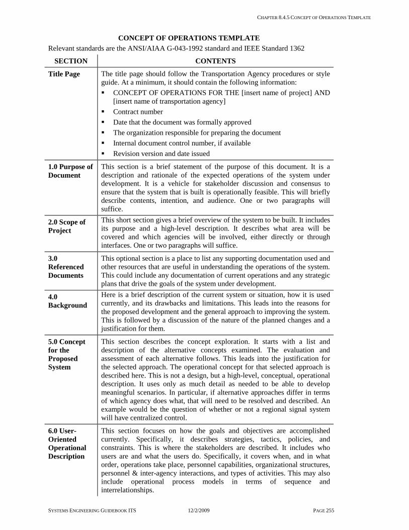
CHAPTER 8.4.5 CONCEPT OF OPERATIONS TEMPLATE
SYSTEMS ENGINEERING GUIDEBOOK ITS 12/2/2009 PAGE 255
CONCEPT OF OPERATIONS TEMPLATE Relevant standards are the ANSI/AIAA G-043-1992 standard and IEEE Standard 1362
SECTION CONTENTS
Title Page The title page should follow the Transportation Agency procedures or style guide. At a minimum, it should contain the following information: CONCEPT OF OPERATIONS FOR THE [insert name of project] AND
[insert name of transportation agency] Contract number Date that the document was formally approved The organization responsible for preparing the document Internal document control number, if available Revision version and date issued
1.0 Purpose of Document
This section is a brief statement of the purpose of this document. It is a description and rationale of the expected operations of the system under development. It is a vehicle for stakeholder discussion and consensus to ensure that the system that is built is operationally feasible. This will briefly describe contents, intention, and audience. One or two paragraphs will suffice.
2.0 Scope of Project
This short section gives a brief overview of the system to be built. It includes its purpose and a high-level description. It describes what area will be covered and which agencies will be involved, either directly or through interfaces. One or two paragraphs will suffice.
3.0 Referenced Documents
This optional section is a place to list any supporting documentation used and other resources that are useful in understanding the operations of the system. This could include any documentation of current operations and any strategic plans that drive the goals of the system under development.
4.0 Background
Here is a brief description of the current system or situation, how it is used currently, and its drawbacks and limitations. This leads into the reasons for the proposed development and the general approach to improving the system. This is followed by a discussion of the nature of the planned changes and a justification for them.
5.0 Concept for the Proposed System
This section describes the concept exploration. It starts with a list and description of the alternative concepts examined. The evaluation and assessment of each alternative follows. This leads into the justification for the selected approach. The operational concept for that selected approach is described here. This is not a design, but a high-level, conceptual, operational description. It uses only as much detail as needed to be able to develop meaningful scenarios. In particular, if alternative approaches differ in terms of which agency does what, that will need to be resolved and described. An example would be the question of whether or not a regional signal system will have centralized control.
6.0 User-Oriented Operational Description
This section focuses on how the goals and objectives are accomplished currently. Specifically, it describes strategies, tactics, policies, and constraints. This is where the stakeholders are described. It includes who users are and what the users do. Specifically, it covers when, and in what order, operations take place, personnel capabilities, organizational structures, personnel & inter-agency interactions, and types of activities. This may also include operational process models in terms of sequence and interrelationships.

CHAPTER 8.4.5 CONCEPT OF OPERATIONS TEMPLATE
SYSTEMS ENGINEERING GUIDEBOOK ITS 12/2/2009 PAGE 256
SECTION CONTENTS
7.0 Operational Needs
Here is a description of the vision, goals & objectives, and personnel needs that drive the requirements for the system. Specifically, this describes what the system needs to do that it is not currently doing.
8.0 System Overview
This is an overview of the system to be developed. This describes its scope, the users of the system, what it interfaces with, its states and modes, the planned capabilities, its goals & objectives, and the system architecture. Note that the system architecture is not a design [that will be done later]. It provides a structure for describing the operations, in terms of where the operations will be carried out, and what the lines of communication will be.
9.0 Operational Environment
This section describes the physical operational environment in terms of facilities, equipment, computing hardware, software, personnel, operational procedures and support necessary to operate the deployed system. For example, it will describe the personnel in terms of their expected experience, skills and training, typical work hours, and other activities [e.g., driving] that must be or may be performed concurrently.
10.0 Support Environment
This describes the current and planned physical support environment. This includes facilities, utilities, equipment, computing hardware, software, personnel, operational procedures, maintenance, and disposal. This includes expected support from outside agencies.
11.0 Operational Scenarios
This is the heart of the document. Each scenario describes a sequence of events, activities carried out by the user, the system, and the environment. It specifies what triggers the sequence, who or what performs each step, when communications occur and to whom or what [e.g., a log file], and what information is being communicated. The scenarios will need to cover all normal conditions, stress conditions, failure events, maintenance, and anomalies and exceptions. There are many ways for presenting scenarios, but the important thing is that each stakeholder can clearly see what his expected role is to be.
12.0 Summary of Impacts
This is an analysis of the proposed system and the impacts on each of the stakeholders. It is presented from the viewpoint of each, so that they can readily understand and validate how the proposed system will impact their operations. Here is where any constraints on system development are documented. Metrics for assessing system performance are also included here.
13.0 Appendices
This is a place to put a glossary, notes, and backup or background material for any of the sections. For example, it might include analysis results in support of the concept exploration.
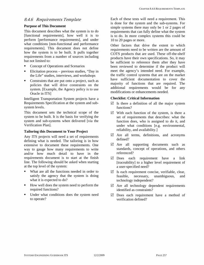
CHAPTER 8.4.6 REQUIREMENTS TEMPLATE
SYSTEMS ENGINEERING GUIDEBOOK ITS 12/2/2009 PAGE 257
8.4.6 Requirements Template Purpose of This Document This document describes what the system is to do [functional requirements], how well it is to perform [performance requirements], and under what conditions [non-functional and performance requirements]. This document does not define how the system is to be built. It pulls together requirements from a number of sources including but not limited to: Concept of Operations and Scenarios Elicitation process – previous studies, “Day in
the Life” studies, interviews, and workshops Constraints that are put onto a project, such as
policies that will drive constraints on the system. [Example, the Agency policy is to use Oracle in ITS]
Intelligent Transportation System projects have a Requirements Specification at the system and sub-system levels. This document sets the technical scope of the system to be built. It is the basis for verifying the system and sub-systems when delivered [via the Verification Plan].
Tailoring this Document to Your Project Any ITS projects will need a set of requirements defining what is needed. The tailoring is in how extensive to document these requirements. One way to gauge how many requirements to write and/or how much detail to have in the requirements document is to start at the finish line. The following should be asked when starting at the top level of the system: What are all the functions needed in order to
satisfy the agency that the system is doing what it is expected to do?
How well does the system need to perform the required functions?
Under what conditions does the system need to operate?
Each of these tests will need a requirement. This is done for the system and the sub-systems. For simple systems there may only be 1 or 2 pages of requirements that can fully define what the system is to do. In more complex systems this could be 10 to 20 pages or more. Other factors that drive the extent to which requirements need to be written are the amount of COTS products that are used. These off-the-shelf products have their own specifications. So, it may be sufficient to reference them after they have been reviewed to determine if the product will meet the agency’s intended need. For example, the traffic control systems that are on the market have sufficient documentation to cover the majority of functions that are required. The additional requirements would be for any modifications or enhancements needed.
Checklist: Critical Information Is there a definition of all the major system
functions? With each function of the system, is there a
set of requirements that describes: what the function does, who is assigned to do it, and under what conditions [e.g. environmental, reliability, and availability.]
Are all terms, definitions, and acronyms defined?
Are all supporting documents such as standards, concept of operations, and others referenced?
Does each requirement have a link [traceability] to a higher level requirement of a user-specified need?
Is each requirement concise, verifiable, clear, feasible, necessary, unambiguous, and technology independent?
Are all technology dependent requirements identified as constraints?
Does each requirement have a method of verification defined?
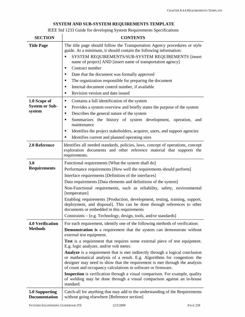
CHAPTER 8.4.6 REQUIREMENTS TEMPLATE
SYSTEMS ENGINEERING GUIDEBOOK ITS 12/2/2009 PAGE 258
SYSTEM AND SUB-SYSTEM REQUIREMENTS TEMPLATE IEEE Std 1233 Guide for developing System Requirements Specifications
SECTION CONTENTS
Title Page The title page should follow the Transportation Agency procedures or style guide. At a minimum, it should contain the following information: SYSTEM REQUIREMENTS/SUB-SYSTEM REQUIREMENTS [insert
name of project] AND [insert name of transportation agency] Contract number Date that the document was formally approved The organization responsible for preparing the document Internal document control number, if available Revision version and date issued
1.0 Scope of System or Sub-system
Contains a full identification of the system Provides a system overview and briefly states the purpose of the system Describes the general nature of the system Summarizes the history of system development, operation, and
maintenance Identifies the project stakeholders, acquirer, users, and support agencies Identifies current and planned operating sites
2.0 Reference Identifies all needed standards, policies, laws, concept of operations, concept exploration documents and other reference material that supports the requirements.
3.0 Requirements
Functional requirements [What the system shall do] Performance requirements [How well the requirements should perform] Interface requirements [Definition of the interfaces] Data requirements [Data elements and definitions of the system] Non-Functional requirements, such as reliability, safety, environmental [temperature] Enabling requirements [Production, development, testing, training, support, deployment, and disposal]. This can be done through references to other documents or embedded in this requirements Constraints – [e.g. Technology, design, tools, and/or standards]
4.0 Verification Methods
For each requirement, identify one of the following methods of verification: Demonstration is a requirement that the system can demonstrate without external test equipment. Test is a requirement that requires some external piece of test equipment. E.g. logic analyzer, and/or volt meter. Analyze is a requirement that is met indirectly through a logical conclusion or mathematical analysis of a result. E.g. Algorithms for congestion: the designer may need to show that the requirement is met through the analysis of count and occupancy calculations in software or firmware. Inspection is verification through a visual comparison. For example, quality of welding may be done through a visual comparison against an in-house standard.
5.0 Supporting Documentation
Catch-all for anything that may add to the understanding of the Requirements without going elsewhere [Reference section]

CHAPTER 8.4.6 REQUIREMENTS TEMPLATE
SYSTEMS ENGINEERING GUIDEBOOK ITS 12/2/2009 PAGE 259
SECTION CONTENTS Examples: diagrams, analysis, key notes, memos, rationale, stakeholders contact list
6.0 Traceability Matrix
This is a table that traces the requirements in this document to the higher level requirements or if this is a top level requirements document, it should trace to the User Requirements or needs
7.0 Glossary Terms, acronyms, definitions
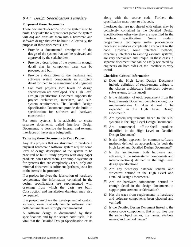
CHAPTER 8.4.7 DESIGN SPECIFICATION TEMPLATE
SYSTEMS ENGINEERING GUIDEBOOK ITS 12/2/2009 PAGE 260
8.4.7 Design Specification Template Purpose of these Documents These documents describe how the system is to be built. They take the requirements [what the system will do] and translate them into a hardware and software design that can be built. Collectively, the purpose of these documents is to: Provide a documented description of the
design of the system that can be reviewed and approved by the stakeholders
Provide a description of the system in enough detail that its component parts can be procured and built
Provide a description of the hardware and software system components in sufficient detail for them to be maintained and upgraded
For most projects, two levels of design specification are developed. The High Level Design Specification Document supports the project architecture, interfaces, and sub-system requirements. The Detailed Design Specification Documents provide the build-to specification for software and hardware construction
For some systems, it is advisable to create separate documents, called Interface Design Documents, to describe the internal and external interfaces of the system being built.
Tailoring these Documents to Your Project Any ITS projects that are structured to produce a physical hardware / software system require some level of design description of the system to be procured or built. Study projects with only paper products don’t need them. For simple systems or for systems that are completely COTS, only one minimal document is sufficient [perhaps just a list of the items to be procured]. If a project involves the fabrication of hardware components, the information contained in the design specifications are supplemented with drawings from which the parts are built. Construction and installation drawings may also be required. If a project involves the development of custom software, even relatively simple software, then both documents are strongly recommended. A software design is documented by these specifications and by the source code itself. It is vital that the Detailed Design Specification exists
along with the source code. Further, the specification must track to this code. Interfaces that are not shared with others may be completely contained in the Detailed Design Specifications otherwise they are specified in the Interface Specification. Some modern programming techniques make processor-to-processor interfaces completely transparent to the code. However, some interface methods, especially interfaces to existing external systems, are very specialized and unique. In these cases, a separate document that can be easily reviewed by engineers on both sides of the interface is very useful.
Checklist: Critical Information Does the High Level Design Document
include definition of requirements unique to the chosen architecture [interfaces between sub-systems, for instance]?
Is the definition of each requirement from the Requirements Document complete enough for implementation? Or, does it need to be expanded in the High Level Design Document?
Are system requirements traced to the sub-systems in the High Level Design Document?
Are commercial off-the-shelf products identified in the High Level or Detailed Design Document?
Is the design approach for common software methods defined, as appropriate, in both the High Level and Detailed Design Documents?
Is the architecture, both hardware and software, of the sub-systems [components and interconnections] defined in the high level design specification?
Are any necessary database schema and structures defined in the High Level and Detailed Design Documents?
Are the hardware components defined in enough detail in the design documents to support procurement or fabrication?
Has the trace from requirements to hardware and software components been checked and verified?
Is the Detailed Design Document linked to the source code components, that is, do they use the same object names, file names, attribute names, and method names?
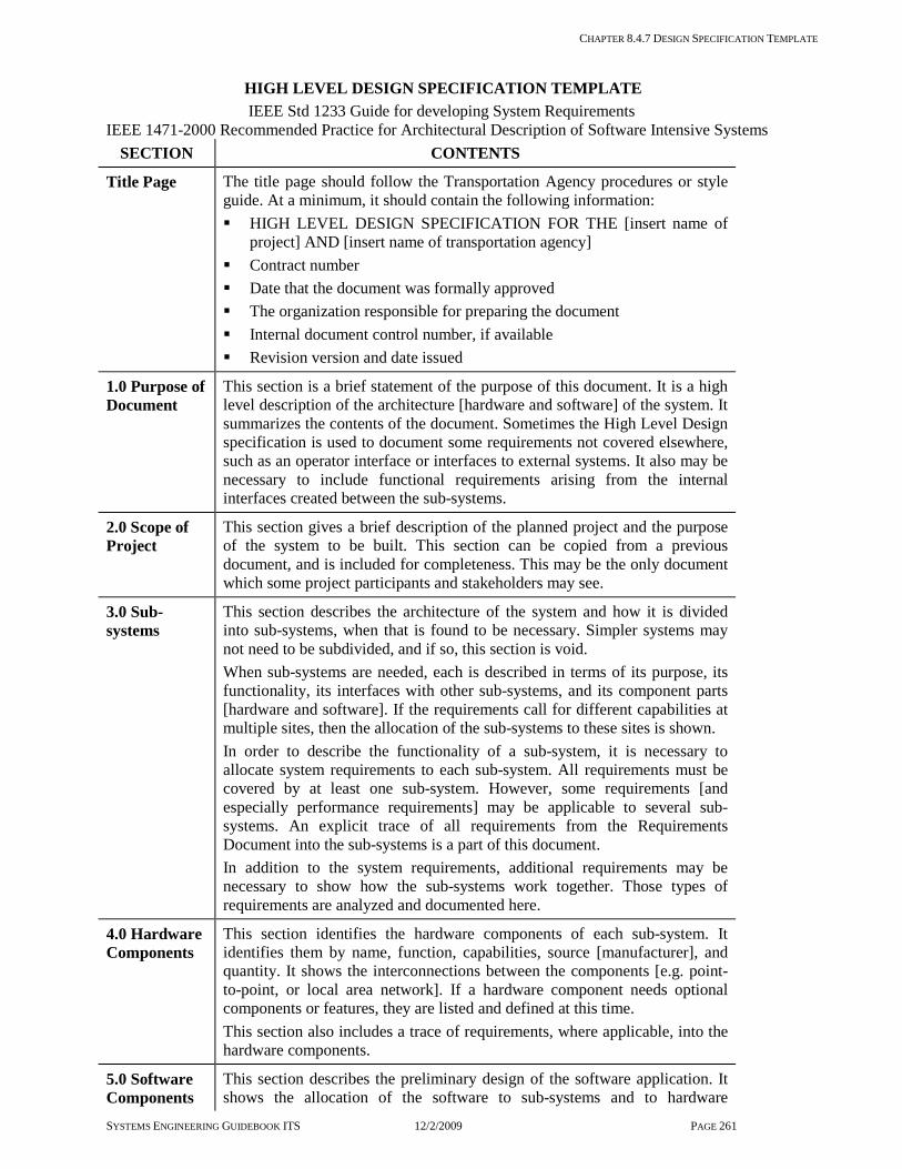
CHAPTER 8.4.7 DESIGN SPECIFICATION TEMPLATE
SYSTEMS ENGINEERING GUIDEBOOK ITS 12/2/2009 PAGE 261
HIGH LEVEL DESIGN SPECIFICATION TEMPLATE IEEE Std 1233 Guide for developing System Requirements IEEE 1471-2000 Recommended Practice for Architectural Description of Software Intensive Systems
SECTION CONTENTS
Title Page The title page should follow the Transportation Agency procedures or style guide. At a minimum, it should contain the following information: HIGH LEVEL DESIGN SPECIFICATION FOR THE [insert name of
project] AND [insert name of transportation agency] Contract number Date that the document was formally approved The organization responsible for preparing the document Internal document control number, if available Revision version and date issued
1.0 Purpose of Document
This section is a brief statement of the purpose of this document. It is a high level description of the architecture [hardware and software] of the system. It summarizes the contents of the document. Sometimes the High Level Design specification is used to document some requirements not covered elsewhere, such as an operator interface or interfaces to external systems. It also may be necessary to include functional requirements arising from the internal interfaces created between the sub-systems.
2.0 Scope of Project
This section gives a brief description of the planned project and the purpose of the system to be built. This section can be copied from a previous document, and is included for completeness. This may be the only document which some project participants and stakeholders may see.
3.0 Sub-systems
This section describes the architecture of the system and how it is divided into sub-systems, when that is found to be necessary. Simpler systems may not need to be subdivided, and if so, this section is void. When sub-systems are needed, each is described in terms of its purpose, its functionality, its interfaces with other sub-systems, and its component parts [hardware and software]. If the requirements call for different capabilities at multiple sites, then the allocation of the sub-systems to these sites is shown. In order to describe the functionality of a sub-system, it is necessary to allocate system requirements to each sub-system. All requirements must be covered by at least one sub-system. However, some requirements [and especially performance requirements] may be applicable to several sub-systems. An explicit trace of all requirements from the Requirements Document into the sub-systems is a part of this document. In addition to the system requirements, additional requirements may be necessary to show how the sub-systems work together. Those types of requirements are analyzed and documented here.
4.0 Hardware Components
This section identifies the hardware components of each sub-system. It identifies them by name, function, capabilities, source [manufacturer], and quantity. It shows the interconnections between the components [e.g. point-to-point, or local area network]. If a hardware component needs optional components or features, they are listed and defined at this time. This section also includes a trace of requirements, where applicable, into the hardware components.
5.0 Software Components
This section describes the preliminary design of the software application. It shows the allocation of the software to sub-systems and to hardware

CHAPTER 8.4.7 DESIGN SPECIFICATION TEMPLATE
SYSTEMS ENGINEERING GUIDEBOOK ITS 12/2/2009 PAGE 262
SECTION CONTENTS elements. It shows and identifies the COTS software packages to be used; and their allocation to sub-systems and to hardware components. It also shows/identifies all custom designed software packages and their allocation to sub-systems and hardware components. It shows the architectural relationship between the various software packages, both custom and COTS. The high level design of each custom software package is described. The method used for this description depends on the methodology being used for software design. That methodology may be object-oriented design, data flow design, structured design, or any other method chosen by the project and the software development team. For example, if an object oriented software design methodology is to be used, the description of the custom software components for the High Level Design specification would include: Preliminary class description for significant internal and external classes necessary to implement the functional requirements Preliminary description of the attributes, methods, and relationships of
each class of objects Class diagrams and other diagramming methods as appropriate, such as,
sequence, package, activity concurrency, and state diagrams Component diagrams to describe the physical partitioning of the software
into code components Descriptions of common patterns to be used in the software design, such
as, the pattern to be used for inter-process communication, or for implementation of an operator interface
Trace requirements into each software package
6.0 Sub-system Requirements
This document may be used to describe additional requirements that were not covered in the requirements specifications. These may include, but are not limited to: Showing greater detail of previously defined functional requirements
based on additional functional analysis; for instance, defining the details of a complex algorithm
Providing complete details of complex requirements, such as a detailed description of a complex operator interface where considerable work with operations personnel is necessary before a definitive statement of the requirement can be made
Providing complete details of an interface with an external system Stating requirements which result from the separation of the system into
sub-systems. That is, identifying functional requirements for the way these sub-systems work together
Of course, these types of requirements [with the exception of the last type] also may be included in the Requirements Document or documented in separate documents, as deemed appropriate.
7.0 Applicable Documents
This section lists the applicable documents that constrain the design process. Such documents may include standards and external system specifications.

CHAPTER 8.4.7 DESIGN SPECIFICATION TEMPLATE
SYSTEMS ENGINEERING GUIDEBOOK ITS 12/2/2009 PAGE 263
DETAILED DESIGN SPECIFICATION TEMPLATE
SECTION CONTENTS
Title Page The title page should follow the Transportation Agency procedures or style guide. At a minimum, it should contain the following information: DETAILED DESIGN SPECIFICATION FOR THE [insert name of
project] AND [insert name of transportation agency] Contract number Date that the document was formally approved The organization responsible for preparing the document Internal document control number, if available Revision version and date issued
1.0 Purpose of Document
This section is a brief statement of the purpose of this document. The purpose is, to expand and complete the preliminary design descriptions included in the High Level Design Document.
2.0 Scope of Project
This section describes the project and may be lifted from the High Level Design Document.
3.0 Sub-systems
This section completes the description of the system architecture and the sub-systems, as necessary.
4.0 Hardware Components
This section completes the description of the hardware components. It contains a detailed list of the exact hardware items to be procured by name, part number, manufacturer, and quantity. If necessary, it lists any hardware component specifications or drawings which have been prepared by the design team.
5.0 Software Components
This section completes the description of the software components. It contains a detailed list of the COTS software products to be procured, by vendor, name, part number, and options. If the project involves custom software applications, this section becomes the dominant and largest part of the Detailed Design Document. Its purpose is to provide enough information so the code can be developed. Subsequently, so the code can be understood for maintenance and system upgrades. As a result, the overriding requirement is that the descriptions of the software components are complete and the link between these descriptions and the actual source code is clear and explicit. The Detailed Design Specification is primarily a completion of the preliminary information in the High Level Design Specification. Any corrections to the information in the previous document should be made at this time. Again, if a software design tool is used, it may produce most of the Detailed Design Specification. For example, if an object oriented software design methodology is to be used, the description of the custom software components for the Detailed Design Specification would include expansion of the following from the High Level Design Specification: Class description for significant internal and external classes necessary to
implement the functional requirements Description of each class attributes, methods, and relationships Class diagrams and other diagramming methods as appropriate, such as:
sequence, package, activity concurrency, and state diagrams Component diagrams to describe the physical partitioning of the software

CHAPTER 8.4.7 DESIGN SPECIFICATION TEMPLATE
SYSTEMS ENGINEERING GUIDEBOOK ITS 12/2/2009 PAGE 264
SECTION CONTENTS into code components
Descriptions of common patterns to be used in the software design, such as, the pattern to be used for inter-process communication, or for implementation of an operator interface
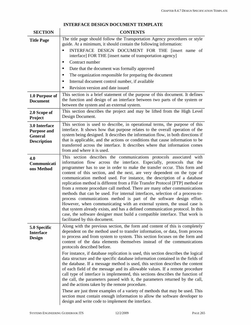
CHAPTER 8.4.7 DESIGN SPECIFICATION TEMPLATE
SYSTEMS ENGINEERING GUIDEBOOK ITS 12/2/2009 PAGE 265
INTERFACE DESIGN DOCUMENT TEMPLATE
SECTION CONTENTS
Title Page The title page should follow the Transportation Agency procedures or style guide. At a minimum, it should contain the following information: INTERFACE DESIGN DOCUMENT FOR THE [insert name of
interface] FOR THE [insert name of transportation agency] Contract number Date that the document was formally approved The organization responsible for preparing the document Internal document control number, if available Revision version and date issued
1.0 Purpose of Document
This section is a brief statement of the purpose of this document. It defines the function and design of an interface between two parts of the system or between the system and an external system.
2.0 Scope of Project
This section describes the project and may be lifted from the High Level Design Document.
3.0 Interface Purpose and General Description
This section is used to describe, in operational terms, the purpose of this interface. It shows how that purpose relates to the overall operation of the system being designed. It describes the information flow, in both directions if that is applicable, and the actions or conditions that cause information to be transferred across the interface. It describes where that information comes from and where it is used.
4.0 Communications Method
This section describes the communications protocols associated with information flow across the interface. Especially, protocols that the programmer has to use in order to make the transfer occur. This form and content of this section, and the next, are very dependent on the type of communication method used. For instance, the description of a database replication method is different from a File Transfer Protocol [FTP] method or from a remote procedure call method. There are many other communications methods that can be used. For internal interfaces, selection of a process-to-process communications method is part of the software design effort. However, when communicating with an external system, the usual case is that system already exists, and has a defined communication protocol. In this case, the software designer must build a compatible interface. That work is facilitated by this document.
5.0 Specific Interface Design
Along with the previous section, the form and content of this is completely dependent on the method used to transfer information, or data, from process to process and from system to system. This section focuses on the form and content of the data elements themselves instead of the communications protocols described before. For instance, if database replication is used, this section describes the logical data structure and the specific database information contained in the fields of the database. If a message method is used, this section describes the content of each field of the message and its allowable values. If a remote procedure call type of interface is implemented, this sections describes the function of the call, the parameters passed with it, the parameters returned by the call, and the actions taken by the remote procedure. These are just three examples of a variety of methods that may be used. This section must contain enough information to allow the software developer to design and write code to implement the interface.

CHAPTER 8.4.8 INTEGRATION PLAN TEMPLATE
SYSTEMS ENGINEERING GUIDEBOOK ITS 12/2/2009 PAGE 266
8.4.8 Integration Plan Template Purpose of this Document A project’s integration and verification strategy is closely tied to the design of the system and its decomposition into sub-systems. The factors that are considered when developing the sub-system design are covered elsewhere in this Guidebook. Whatever the goals were [and they vary from project to project], the Integration Plan needs to be structured to bring the components together to create each sub-system and to bring the various sub-systems together to make the whole system. Further, this needs to be done in a way that supports the deployment strategy. That is the first purpose of an Integration Plan. The second purpose is to describe to the participants in each integration step what has to be done. The integration team has to assemble various resources for each integration step. The Integration Plan identifies the needed resources. In addition, it identifies when and where the resources will be needed.
Tailoring this Document to Your Project An Integration Plan, at least as a separate written document, is not always needed. The complexity of the system, the complexity of the eventual deployment of the system, and the complexity of the development effort influence the decision to prepare an Integration Plan. For instance, a deployment strategy that calls for multiple installations at multiple locations can require a complex sequence of integration activities. Another common complexity of integration arises when different teams are developing the sub-systems. This is especially true when the different development teams are comprised of different contractors, each with their own contract. In this case, they need to know more about their required work to support integration than would be the case if the same development team were working both sides of the integration effort. The same type of complexity comes into play when an integration
step involves external systems owned by other agencies, or at least other organizations within the agency. If a separate Integration Plan is not warranted, the necessary planning information can be included in: the Project Plan, the SEMP, the Verification Plan and the software development plans of the development team.
Checklist: Critical Information Does the Integration Plan include and cover
integration of all of the components and sub-systems, either developed or purchased, of the project?
Does the Integration Plan account for all external systems to be integrated with the system [for example, communications networks, field equipment, other complete systems owned by the agency or owned by other agencies]?
Does the Integration Plan fully support the deployment strategy. For example, when and where the sub-systems and system is to be deployed?
Are the integration steps defined in the Integration Plan consistent with the verification activities defined in the Verification Plan?
For each integration step, does the Integration Plan define what components and sub-systems are to be integrated?
For each integration step, does the Integration Plan identify all the needed participants and define what their roles and responsibilities are?
Does the Integration Plan establish the sequence and schedule for every integration step?
Does the Integration Plan spell out how integration problems are to be documented and resolved?

CHAPTER 8.4.8 INTEGRATION PLAN TEMPLATE
SYSTEMS ENGINEERING GUIDEBOOK ITS 12/2/2009 PAGE 267
INTEGRATION PLAN TEMPLATE
SECTION CONTENTS
Title Page The title page should follow the Transportation Agency procedures or style guide. At a minimum, it should contain the following information: INTEGRATION PLAN FOR THE [insert name of project] AND [insert
name of transportation agency] Contract number Date that the document was formally approved The organization responsible for preparing the document Internal document control number, if available Revision version and date issued
1.0 Purpose of Document
A brief statement of the purpose of this document. It is, the plan for integrating the components and sub-systems of the project prior to verification.
2.0 Scope of Project
This section gives a brief description of the planned project and the purpose of the system to be built. Special emphasis is placed on the project’s deployment complexities and challenges. This section may be lifted from earlier documents. It is important only to people [stakeholders] who will be introduced to the project for the first time by this document.
3.0 Integration Strategy
This section informs the reader what the high level plan is for integration and, most importantly, why the integration plan is structured the way it is. As mentioned before, the Integration Plan is subject to several constraints, sometimes conflicting constraints. Also, it is one part of the larger process of build, integrate, verify, and deploy. All of which must be synchronized to support the same project strategy. So, for even a moderately complex project, the integration strategy, based on a clear and concise statement of the project’s goals and objectives, is described here at a high, but all-inclusive, level. It may also be necessary to describe the analysis of alternative strategies to make it clear why this particular strategy was selected. The same strategy is the basis for the Build Plan, the Verification Plan, and the Deployment Plan. So, it may only be necessary to justify this strategy once, perhaps in the Project Plan, or in the SEMP. This section covers and describes each step in the integration process. It describes what components are integrated at each step and gives a general idea of what threads of the operational capabilities [requirements] are covered. It ties the plan to the previously identified goals and objectives so the stakeholders can understand the rationale for each integration step. This summary level description also defines the schedule for all the integration efforts.
4.0 Phase 1 Integration
This, and the following sections, define and explain each step in the integration process. The intent here is to identify all the needed participants and to describe to them what they have to do. In general, the description of each integration step should identify: The location of the activities The project-developed equipment and software products to be integrated
Initially this is just a high level list but eventually the list must be exact and complete, showing part numbers and quantity
Any support equipment [special software, test hardware, software stubs,
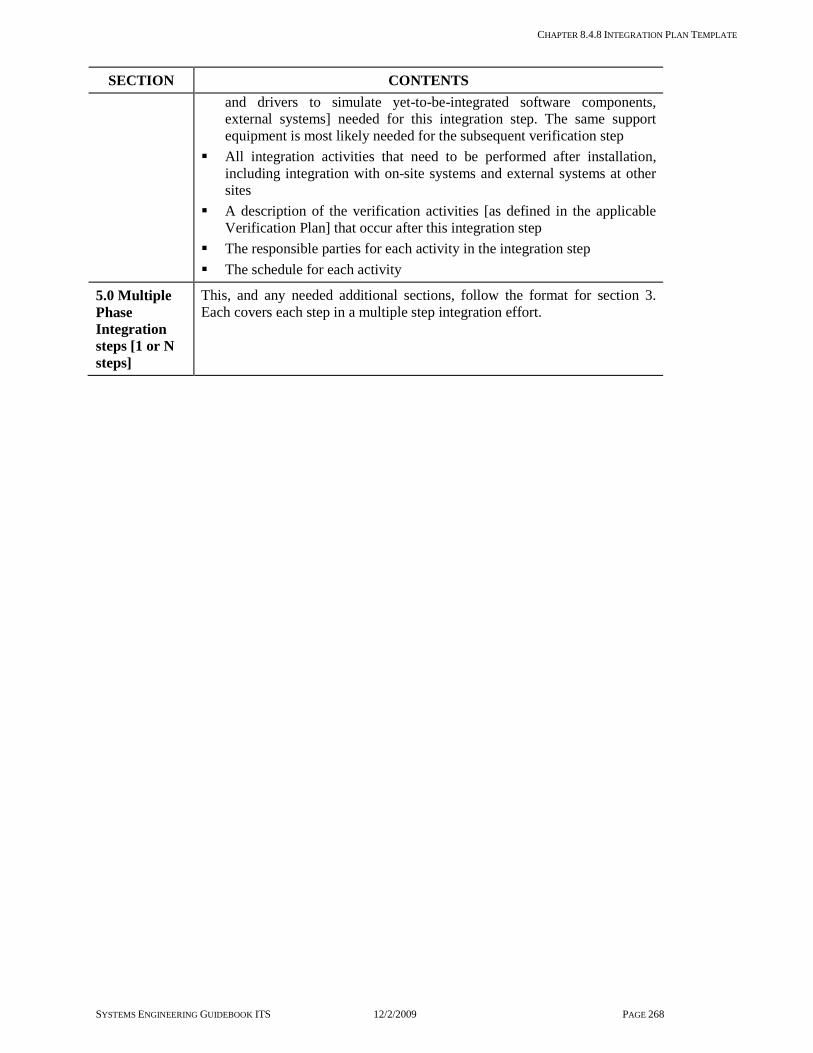
CHAPTER 8.4.8 INTEGRATION PLAN TEMPLATE
SYSTEMS ENGINEERING GUIDEBOOK ITS 12/2/2009 PAGE 268
SECTION CONTENTS and drivers to simulate yet-to-be-integrated software components, external systems] needed for this integration step. The same support equipment is most likely needed for the subsequent verification step
All integration activities that need to be performed after installation, including integration with on-site systems and external systems at other sites
A description of the verification activities [as defined in the applicable Verification Plan] that occur after this integration step
The responsible parties for each activity in the integration step The schedule for each activity
5.0 Multiple Phase Integration steps [1 or N steps]
This, and any needed additional sections, follow the format for section 3. Each covers each step in a multiple step integration effort.

CHAPTER 8.4.9 VERIFICATION DOCUMENTS TEMPLATE
SYSTEMS ENGINEERING GUIDEBOOK ITS 12/2/2009 PAGE 269
8.4.9 Ver ification Documents Template
Purpose of these Documents These documents plan, describe, and record the activity of verifying that the system being built meets the specified requirements. Since a complex system may involve a series of verification activities, several sets of these verification documents may be needed. All of these verification documents follow the master plan for verification defined in the Systems Engineering Management Plan. Usually, for even moderately complex systems, the following three levels of verification documents are prepared: a plan to initially lay out the specific
verification effort a procedure that is the specific and detailed
steps to be followed to perform the test a report on the results of the testing activity These three documents are described in this section. A critical issue is assuring that all requirements are verified by the testing activity. This is best done by first tracing each requirement into a test case then, into a step in the Verification Procedure. Additional Information is found in IEEE 1012-1998, Software Verification and Validation.
Tailoring these Documents to Your Project A separate Verification Plan and procedure may not be required for the simplest projects, especially where the system is essentially COTS and does not involve any custom software development, and where the project office personnel have a very clear understanding of the purpose of the system. In some cases, it is possible to take a copy of the Requirements Document, improvise procedures, and annotate the Requirements Document with the results of each test step. This can be a perfectly acceptable way to verify the operations of a system. However, preparation of these verification documents is strongly advised if: the system is more complex
there are a number of separate verification activities
multiple deployment sites are involved more than one or two stakeholders have to be
satisfied There is also the question of how comprehensive to make the verification effort. It is impossible to test everything, that is, all possible combinations of actions under all possible operational situations. A good rule of thumb is: if it was important enough to write down as a requirement, then it should be tested, at least once, as part of a reasonable operational scenario. This may not, for example, test all possible failure mode conditions. If a good job was done in writing the requirements, then the most important and most likely are verified.
Checklist: Critical Information Is there a documented Verification Plan for
the Project? Does the Verification Plan answer all the
questions of who, what, where, and when concerning test conduct?
Does the Verification Plan make clear what needs to happen if a test failure is encountered?
Does the Verification Plan define the configuration of the hardware, software, and external system needed for each test case?
Are all applicable requirements traced to a test case in the Verification Plan? Does each test case define a realistic and doable test?
Are detailed verification procedures documented for the project?
Is each step in the Verification Procedure traced to a test case and a requirement?
Are all of the necessary initial conditions and set-up defined for each procedure?
Has each verification procedure been dry run prior to the formal test? Have the procedures been updated as a result?
Is there a Verification Report that documents the project verification results?
Does the Verification Report describe, in detail, the resolution of every test anomaly encountered during testing?

CHAPTER 8.4.9 VERIFICATION DOCUMENTS TEMPLATE
SYSTEMS ENGINEERING GUIDEBOOK ITS 12/2/2009 PAGE 270
VERIFICATION PLAN TEMPLATE IEEE 1012-1998 Independent Verification and Validation
SECTION CONTENTS
Title Page The title page should follow the Transportation Agency procedures or style guide. At a minimum, it should contain the following information: VERIFICATION PLAN FOR THE [insert name of project] AND [insert
name of transportation agency] Contract number Date that the document was formally approved The organization responsible for preparing the document Internal document control number, if available Revision version and date issued
1.0 Purpose of Document
This section identifies the type of verification activity to be performed within this Verification Plan. For instance, this activity may verify the entire system, a sub-system, the deployment at a site, a burn-in test, or any other verification activity called for in the Program Plan or in the SEMP.
2.0 Scope of Project
This section gives a brief description of the planned project and the purpose of the system to be built. Special emphasis is placed on the project’s complexities and challenges that must be addressed and verified by the systems engineering efforts. This section also describes the environment in which the project operates. It identifies the organization structures that encompass all stakeholders. It also gives a brief description of the role to be played by each stakeholder. This includes ad hoc and existing management work groups and multi-disciplinary technical teams that should be formed for supporting the project. Such teams are critical to reaching successful system deployment.
3.0 Referenced Documents
This is a list of all documents used in the preparation of this Verification Plan. This almost always includes the Project Plan, the SEMP [if one was written], and the applicable Requirements Documents. However, reference of other documents, such as descriptions of external systems, standards, a Concept of Operations, and manuals may need to be included.
4.0 Test Conduct
This section provides details on how the testing is accomplished. It defines: who does the testing; when and where it is to be done; the responsibilities of each participant before, during, and after each test; the hardware and software to be used [and other systems as well]; and the documents to be prepared as a record of the testing activity. Another very important part of this section defines how testing anomalies are to be handled [that is, what to do when a test fails]. In general, the following information should be included in this section: A description of the participating organizations and personnel and
identification of their roles and responsibilities. This may include for example, a test conductor, test recorder, operators, and/or engineering support.
Identification of the location of the testing effort, that is, the place, or places, where the testing progress must be observed.
The hardware and software configuration for all of the test cases, including hardware and software under test and any supporting test equipment, software, or external systems. Several configurations may be necessary.

CHAPTER 8.4.9 VERIFICATION DOCUMENTS TEMPLATE
SYSTEMS ENGINEERING GUIDEBOOK ITS 12/2/2009 PAGE 271
SECTION CONTENTS Identification of the documents to be prepared to support the testing,
including Verification Procedures, a Verification Report and descriptions of special test equipment and software.
Details on the actual conduct of the testing, including: - Notification of participants - Emphasis on the management role of the test conductor - Procedures for approving last minute changes to the procedures - The processes for handling a test failure, including recording of critical
information, determination of whether to stop the testing, restart, or skip a procedure, resolution of the cause of a failure [e.g. fix the software, reset the system, and/or change the requirements], and determination of the retesting activities necessary as a result of the failure.
5.0 Test Identification
This section is the heart, and largest, section of the Verification Plan. Here we identify the specific test cases to be performed. A test case is a logical grouping of functions and performance criteria [all from the Requirements Documents] that is to be tested together. For instance, a specific test case may cover all the control capabilities to be provided for control of a changeable message sign. There may be several individual requirements that define this capability, and they all are verified in one test case. The actual grouping of requirements into a test case is arbitrary. They should be related and easily combined into a reasonable set of test procedure actions. Each test case should contain at least the following information: A description name and a reference number A complete list of the requirements to be verified. For ease of tracing of
requirements into the Verification Plan and other documents, the requirements are given numbers. They can be accurately and conveniently referenced without repeating all the words of the requirement
A description of the objective of the test case, usually taken from the wording of the requirements, to aide the reader understanding the scope of the test case
Any data to be recorded or noted during the test, such as expected results of a test step. Other data, such as a recording of a digital message sent to an external system, may be required to verify the performance of the system.
A statement of the pass/fail criteria. Often, this is just a statement that the system operates per the requirements
A description of the test configuration. That is a list of the hardware and software items needed for the test and how they should be connected. Often, the same configuration is used for several tests
A list of any other important assumptions and constraints necessary for conduct of the test case

CHAPTER 8.4.9 VERIFICATION DOCUMENTS TEMPLATE
SYSTEMS ENGINEERING GUIDEBOOK ITS 12/2/2009 PAGE 272
VERIFICATION PROCEDURE TEMPLATE
SECTION CONTENTS
Title Page The title page should follow the Transportation Agency procedures or style guide. At a minimum, it should contain the following information: VERIFICATION PROCEDURE FOR THE [insert name of project]
AND [insert name of transportation agency] Contract number Date that the document was formally approved The organization responsible for preparing the document Internal document control number, if available Revision version and date issued
1.0 Purpose of Document
This section identifies the type of verification to be performed. For instance, this activity may verify the entire system, a sub-system, the deployment at a site, a burn-in test, or any other verification activity called for in the Program Plan or in the SEMP.
2.0 Verification Configuration and Software Under Test
This section identifies the equipment and software to be verified. It also identifies all equipment and software necessary for this verification activity that is external to the system / sub-system configuration under test. This may include special test equipment and any external systems with an interface to the configuration under test. For the hardware / software configuration under test, this section identifies: Each hardware item by part number and serial number Each item of commercial-off-the-shelf [COTS] software, by part number
and version number Each source code file of custom developed software, by file name and
version number For all special test equipment / software, this section identifies:
- Each hardware item by part, serial, and version number - Each item of COTS software, by part number and version number - Each source code file of custom developed software by file name and
version number For each external system interface, this section identifies: The name and location of the external system
3.0 Verification Setup
This section describes the steps to be taken to set up each verification configuration, including, but not limited to, tuning of the hardware, configuring and starting the software, starting the special test software, and set-up steps at each external system to be used.
4.0 Verification Procedures
This section describes the step-by-step actions to be taken by the verification operator for each verification case. Each step includes: Operator action to be taken. This operator action may be, for example, an
entry at a workstation, initiation of a routine in the special test software, or an action at an external system.
Expected result to be observed. This too may take several forms, for example, display of certain information at a workstation, a response at an external system, recording of data for subsequent analysis, or an action by a field device.
Pass / fail entry space. Here the verification conductor records whether or not the expected result occurred. If the expected results are not observed, then the procedures for dealing with failures contained in the Verification

CHAPTER 8.4.9 VERIFICATION DOCUMENTS TEMPLATE
SYSTEMS ENGINEERING GUIDEBOOK ITS 12/2/2009 PAGE 273
SECTION CONTENTS Plan are invoked.
A trace of each verification step from a verification case in the applicable Verification Plan and a trace from a requirement in the applicable Requirements Document.

CHAPTER 8.4.9 VERIFICATION DOCUMENTS TEMPLATE
SYSTEMS ENGINEERING GUIDEBOOK ITS 12/2/2009 PAGE 274
VERIFICATION REPORT TEMPLATE
SECTION CONTENTS
Title Page The title page should follow the Transportation Agency procedures or style guide. At a minimum, it should contain the following information: VERIFICATION REPORT FOR THE [insert name of project] AND
[insert name of transportation agency] Contract number Date that the document was formally approved The organization responsible for preparing the document Internal document control number, if available Revision version and date issued
1.0 Purpose of Document
This section identifies the type of verification performed. For instance, the activity may verify the entire system, a sub-system, the deployment at a site, a burn-in test, or any other verification activity called for in the Program Plan or in the SEMP. This section can be taken from the applicable Verification Procedure.
2.0 Identification of the Configuration under test
This section identifies the equipment and software verified. It also identifies all equipment and software necessary for this verification activity that is external to the system / sub-system configuration under test. This may include special test equipment and any external systems with an interface to the configuration under test. This section can be taken from the applicable Verification Procedure.
3.0 Individual Test Case Report
This section summarizes the purpose and results of each test case performed in the applicable Verification Procedure. Special attention is paid to any test case where a failure occurred and how the failure was resolved. This section covers: Test case overview and results Completed Verification Procedure pages annotated with pass / fail results Description of each failure, if any, from the expected result called for in
the Verification Procedure Any back-up data or records related to the field procedure Details of the resolution of each test failure, including procedure
modification, software fix, re-testing and results, regression testing and results, and required document changes [including changes to the requirements].
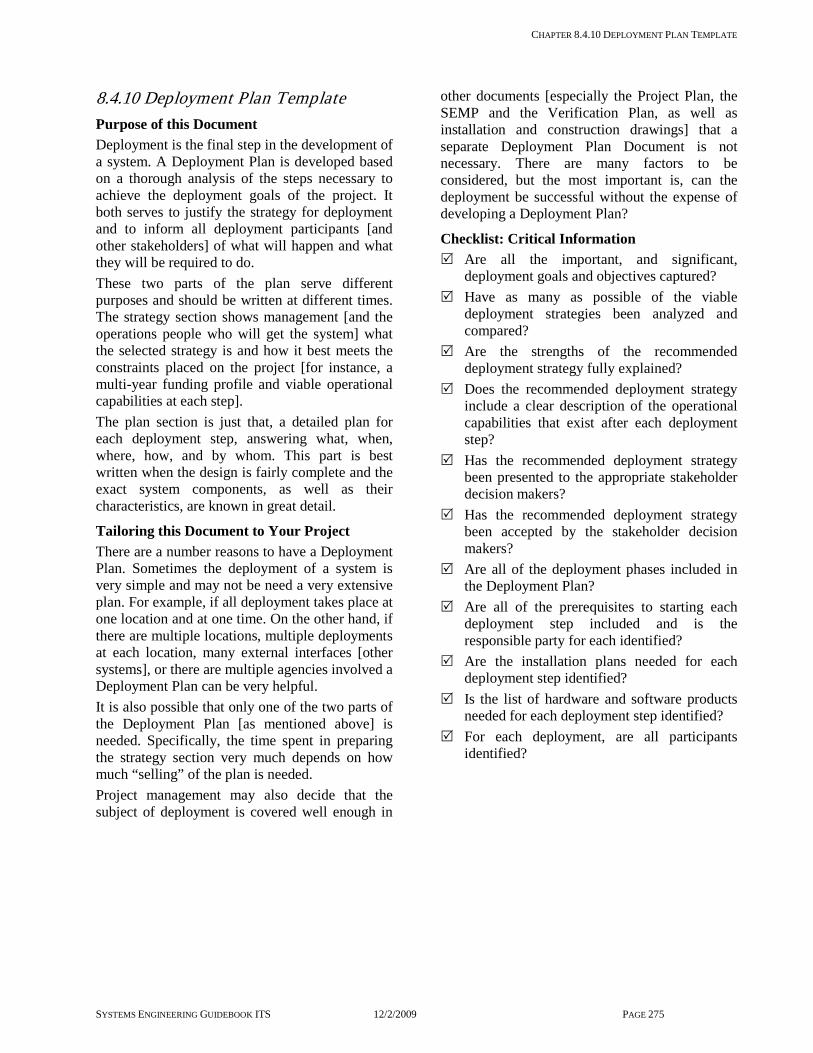
CHAPTER 8.4.10 DEPLOYMENT PLAN TEMPLATE
SYSTEMS ENGINEERING GUIDEBOOK ITS 12/2/2009 PAGE 275
8.4.10 Deployment Plan Template Purpose of this Document Deployment is the final step in the development of a system. A Deployment Plan is developed based on a thorough analysis of the steps necessary to achieve the deployment goals of the project. It both serves to justify the strategy for deployment and to inform all deployment participants [and other stakeholders] of what will happen and what they will be required to do. These two parts of the plan serve different purposes and should be written at different times. The strategy section shows management [and the operations people who will get the system] what the selected strategy is and how it best meets the constraints placed on the project [for instance, a multi-year funding profile and viable operational capabilities at each step]. The plan section is just that, a detailed plan for each deployment step, answering what, when, where, how, and by whom. This part is best written when the design is fairly complete and the exact system components, as well as their characteristics, are known in great detail.
Tailoring this Document to Your Project There are a number reasons to have a Deployment Plan. Sometimes the deployment of a system is very simple and may not be need a very extensive plan. For example, if all deployment takes place at one location and at one time. On the other hand, if there are multiple locations, multiple deployments at each location, many external interfaces [other systems], or there are multiple agencies involved a Deployment Plan can be very helpful. It is also possible that only one of the two parts of the Deployment Plan [as mentioned above] is needed. Specifically, the time spent in preparing the strategy section very much depends on how much “selling” of the plan is needed. Project management may also decide that the subject of deployment is covered well enough in
other documents [especially the Project Plan, the SEMP and the Verification Plan, as well as installation and construction drawings] that a separate Deployment Plan Document is not necessary. There are many factors to be considered, but the most important is, can the deployment be successful without the expense of developing a Deployment Plan?
Checklist: Critical Information Are all the important, and significant,
deployment goals and objectives captured? Have as many as possible of the viable
deployment strategies been analyzed and compared?
Are the strengths of the recommended deployment strategy fully explained?
Does the recommended deployment strategy include a clear description of the operational capabilities that exist after each deployment step?
Has the recommended deployment strategy been presented to the appropriate stakeholder decision makers?
Has the recommended deployment strategy been accepted by the stakeholder decision makers?
Are all of the deployment phases included in the Deployment Plan?
Are all of the prerequisites to starting each deployment step included and is the responsible party for each identified?
Are the installation plans needed for each deployment step identified?
Is the list of hardware and software products needed for each deployment step identified?
For each deployment, are all participants identified?

CHAPTER 8.4.10 DEPLOYMENT PLAN TEMPLATE
SYSTEMS ENGINEERING GUIDEBOOK ITS 12/2/2009 PAGE 276
DEPLOYMENT PLAN TEMPLATE
SECTION CONTENTS
Title Page The title page should follow the Transportation Agency procedures or style guide. At a minimum, it should contain the following information: DEPLOYMENT PLAN FOR THE [insert name of project] AND [insert
name of transportation agency] Contract number Date that the document was formally approved The organization responsible for preparing the document Internal document control number, if available Revision version and date issued
1.0 Purpose of Document
A brief statement of the purpose of this document. It is the plan for deploying the systems of the project over one or more phases and into one or more physical locations [sites].
2.0 Scope of Project
This section gives a brief description of the planned project and the purpose of the system to be built. Special emphasis is placed on the project’s deployment complexities and challenges. This section may be lifted from earlier documents. It is important only to people [stakeholders] who will be introduced to the project for the first time by this document.
3.0 Deployment 4.0 Strategy
A complex deployment, involving multiple deployment steps at multiple sites, is based on certain goals and objectives. This section lists those goals and objectives and is used to “sell” the Deployment Plan to the stakeholders. It is also important that the deployment participants understand why the deployment is proceeding as it is so they can work with and support the plan. The significant goals and objectives guiding the deployment strategy should be relatively few [no more than a dozen] and need to be clearly stated in this section. Some typical examples of goals and objectives include: The funding profile for a multi-year project which limits the scope of
deployment in a single year Development and installation prerequisites. An analysis of the system
may show that feature A must be deployed first before features B, C or D, all of which need A to function
Construction activities that must precede deployment Deployment of interfacing systems [especially by other agencies] that
must precede deployment of a system feature The need to create a viable operational capability at each stage of the
deployment. This influences how much of the system must be deployed at each step
Following the statement of the goals and objectives, a high level view of the deployment strategy is presented. This covers and describes each phase of deployment at each of the sites involved. It describes: what is deployed, where it is deployed, and what operational capabilities are the results of this phase of the deployment. It ties the plan to the previously identified goals and objectives so the stakeholders can understand the rationale for each phase. This summary should include an estimate of the cost of each phase to show the plan satisfies the funding profile. It should also show the overall deployment schedule.
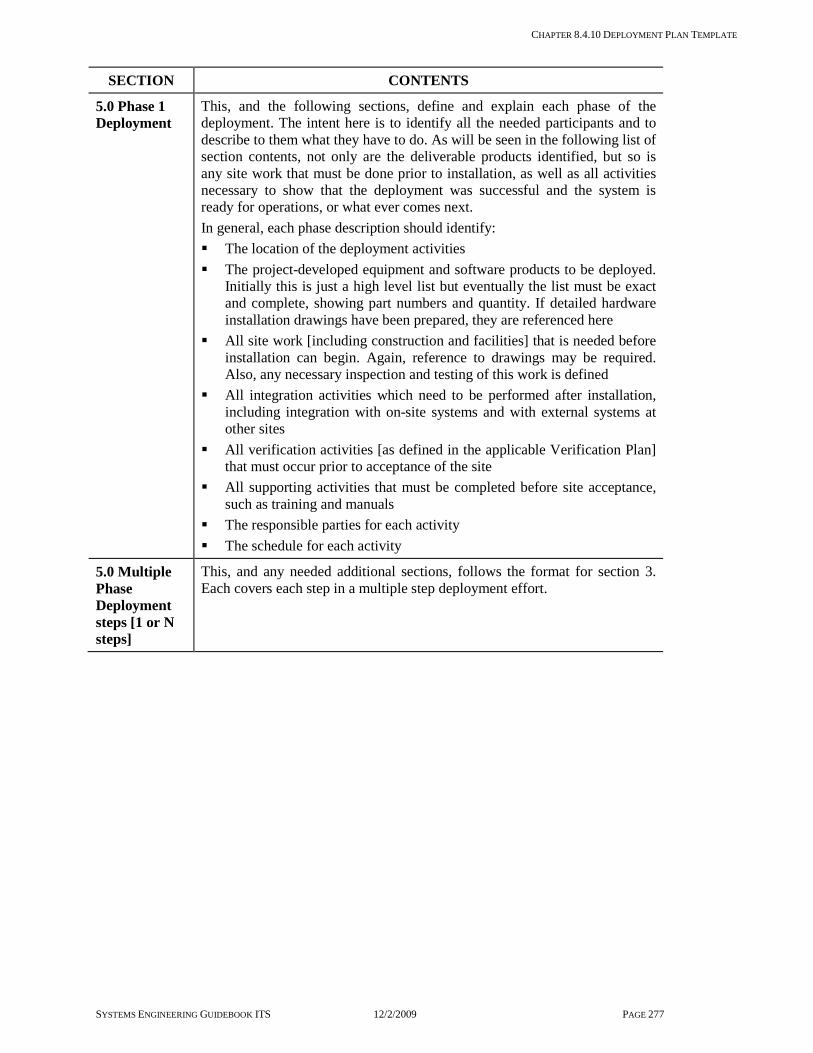
CHAPTER 8.4.10 DEPLOYMENT PLAN TEMPLATE
SYSTEMS ENGINEERING GUIDEBOOK ITS 12/2/2009 PAGE 277
SECTION CONTENTS
5.0 Phase 1 Deployment
This, and the following sections, define and explain each phase of the deployment. The intent here is to identify all the needed participants and to describe to them what they have to do. As will be seen in the following list of section contents, not only are the deliverable products identified, but so is any site work that must be done prior to installation, as well as all activities necessary to show that the deployment was successful and the system is ready for operations, or what ever comes next. In general, each phase description should identify: The location of the deployment activities The project-developed equipment and software products to be deployed.
Initially this is just a high level list but eventually the list must be exact and complete, showing part numbers and quantity. If detailed hardware installation drawings have been prepared, they are referenced here
All site work [including construction and facilities] that is needed before installation can begin. Again, reference to drawings may be required. Also, any necessary inspection and testing of this work is defined
All integration activities which need to be performed after installation, including integration with on-site systems and with external systems at other sites
All verification activities [as defined in the applicable Verification Plan] that must occur prior to acceptance of the site
All supporting activities that must be completed before site acceptance, such as training and manuals
The responsible parties for each activity The schedule for each activity
5.0 Multiple Phase Deployment steps [1 or N steps]
This, and any needed additional sections, follows the format for section 3. Each covers each step in a multiple step deployment effort.

CHAPTER 8.4.11 VALIDATION DOCUMENTS TEMPLATE
SYSTEMS ENGINEERING GUIDEBOOK ITS 12/2/2009 PAGE 278
8.4.11 Validation Documents Template Purpose of these Documents These documents plan, describe, and record the activity of validating that the system meets the intended purpose and needs of the systems’ owner and stakeholders. Since a complex system may involve a series of validation related activities, several sets of these documents may be needed. All of these validation documents follow the master plan for validation defined in the Systems Engineering Management Plan. Usually, for even moderately complex systems, the following two levels of validation documents are prepared: a plan to lay out the specific validation efforts a report on the results of the validation
activity These documents are described in this section. Note that for this phase there is no set of detailed procedures. Validation as described in section 3.7.1 involves stakeholders and the actual users of the system. The Validation Plan will lay out the overall expectations for the assessment of the completed system but will let the users work the system as part of their every day job rather than imposing a strict step-by-step procedure. It is their system after all and they need to be comfortable with it and provide the final answer on how well it satisfies their needs. Reporting the results and any corrective actions needed will be part of this effort. A critical issue is assuring that all user needs are included in the validation activity. This is best done by first tracing each of the needs documented in the Concept of Operations into a validation activity. Additional Information is found in IEEE 1012-1998, Software Verification and Validation.
Tailoring these Documents to Your Project A separate Validation Plan may not be required for the simplest projects, especially where the system is essentially COTS and does not involve any custom software development, and where the project office personnel have a very clear understanding of the purpose of the system. In some cases, it is possible to take a copy of the ConOps Document, improvise an outline or scenario to check-off the validated system, and annotate the ConOps with the results of the
assessment. This can be a perfectly acceptable way to validate the performance of a simple system. However, preparation of these validation documents is strongly advised if: the system is more complex there are a number of separate validation
activities multiple deployment sites are involved more than one or two stakeholders have to be
satisfied There is also the question of how comprehensive to make the validation effort. It is impossible to cover everything, that is, all possible combinations of actions under all possible operational situations. A good rule of thumb is: if it was important enough to write down as a need, then it should be validated, at least once, as part of using the system in a real-world environment. This may not, for example, test all possible failure mode conditions. If a good job was done in earlier phases of testing and verification then the most important and most likely scenarios are covered.
Checklist: Critical Information Is there a documented Validation Plan for the
system of interest? Does the Validation Plan answer all the
questions of who, what, where, and when concerning validation?
Does the Validation Plan make clear what needs to happen if a problem is encountered?
Does the Validation Plan define the environmental conditions and systems configuration needed for each scenario?
Are all applicable user needs traced to an event in the Validation Plan? Does each validation event define a realistic and doable scenario?
Was a Validation Report developed that documents the validation results?
Does the Validation Report describe, in detail, the resolution of every anomaly encountered during testing?
Does the Validation Report include recommendations from the users and stakeholders to address the situation in future system evolutions?

CHAPTER 8.4.11 VALIDATION DOCUMENTS TEMPLATE
SYSTEMS ENGINEERING GUIDEBOOK ITS 12/2/2009 PAGE 279
VALIDATION PLAN TEMPLATE IEEE 1012-1998 Independent Verification and Validation
SECTION CONTENTS
Title Page The title page should follow the Transportation Agency procedures or style guide. At a minimum, it should contain the following information: VALIDATION PLAN FOR THE [insert name of project] AND [insert
name of transportation agency] Contract number Date that the document was formally approved The organization responsible for preparing the document Internal document control number, if available Revision version and date issued
1.0 Purpose of Document
This section identifies the type of validation activity to be performed within this Plan. For instance, this activity may validate the entire system, a sub-system, the deployment at a site, or any other validation activity called for in the Program Plan or in the SEMP.
2.0 Scope of Project
This section gives a brief description of the planned project and the purpose of the system to be built. Special emphasis is placed on the project’s complexities and challenges that must be addressed by the systems engineering efforts. This section also describes the environment in which the project operates. It identifies the organization structures that encompass all stakeholders. It also gives a brief description of the role to be played by each stakeholder. This includes ad hoc and existing management work groups and multi-disciplinary technical teams that should be formed for supporting the project. Such teams are critical to reaching successful system deployment.
3.0 Referenced Documents
This is a list of all documents used in the preparation of this Validation Plan. This almost always includes the Project Plan, the SEMP [if one was written], and the Concept of Operations. However, reference of other documents, such as descriptions of external systems, standards, and manuals may need to be included.
4.0 Validation Conduct
This section provides details on how the validation is accomplished. It defines: who does it; when and where it is to be done; the responsibilities of each participant before, during, and after each event/activity; the hardware and software to be used [and other systems as well]; and the documents to be prepared as a record of the activity. Another very important part of this section defines how anomalies are to be handled [that is, what to do when something fails or, in the case of Validation, does not match the documented needs or does not satisfactorily address the original problem]. In general, the following information should be included in this section: A description of the participating organizations and personnel and
identification of their roles and responsibilities. This may include for example, the operators, an event recorder, witnesses, and/or engineering support. Some agencies prefer to have contractors not around during validation, others want access to them in case questions or problems arise.
Identification of the location of the activity, that is, the place, or places, where the progress must be observed.
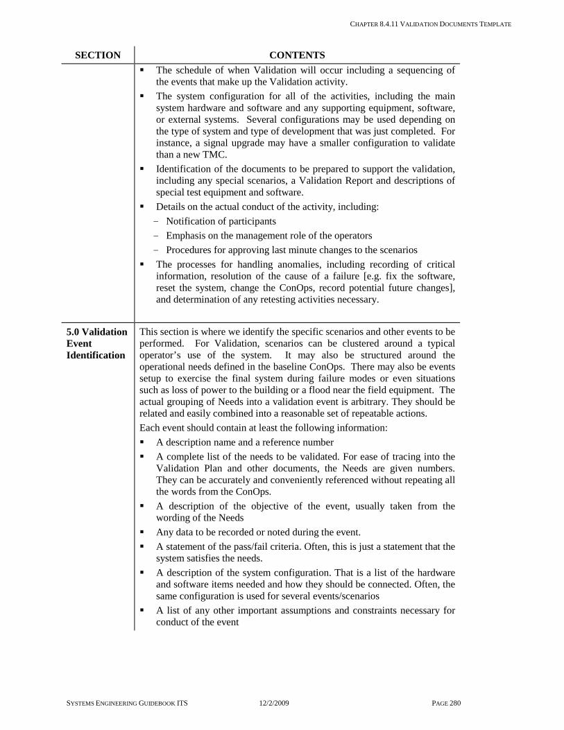
CHAPTER 8.4.11 VALIDATION DOCUMENTS TEMPLATE
SYSTEMS ENGINEERING GUIDEBOOK ITS 12/2/2009 PAGE 280
SECTION CONTENTS The schedule of when Validation will occur including a sequencing of
the events that make up the Validation activity. The system configuration for all of the activities, including the main
system hardware and software and any supporting equipment, software, or external systems. Several configurations may be used depending on the type of system and type of development that was just completed. For instance, a signal upgrade may have a smaller configuration to validate than a new TMC.
Identification of the documents to be prepared to support the validation, including any special scenarios, a Validation Report and descriptions of special test equipment and software.
Details on the actual conduct of the activity, including: - Notification of participants - Emphasis on the management role of the operators - Procedures for approving last minute changes to the scenarios
The processes for handling anomalies, including recording of critical information, resolution of the cause of a failure [e.g. fix the software, reset the system, change the ConOps, record potential future changes], and determination of any retesting activities necessary.
5.0 Validation Event Identification
This section is where we identify the specific scenarios and other events to be performed. For Validation, scenarios can be clustered around a typical operator’s use of the system. It may also be structured around the operational needs defined in the baseline ConOps. There may also be events setup to exercise the final system during failure modes or even situations such as loss of power to the building or a flood near the field equipment. The actual grouping of Needs into a validation event is arbitrary. They should be related and easily combined into a reasonable set of repeatable actions. Each event should contain at least the following information: A description name and a reference number A complete list of the needs to be validated. For ease of tracing into the
Validation Plan and other documents, the Needs are given numbers. They can be accurately and conveniently referenced without repeating all the words from the ConOps.
A description of the objective of the event, usually taken from the wording of the Needs
Any data to be recorded or noted during the event. A statement of the pass/fail criteria. Often, this is just a statement that the
system satisfies the needs. A description of the system configuration. That is a list of the hardware
and software items needed and how they should be connected. Often, the same configuration is used for several events/scenarios
A list of any other important assumptions and constraints necessary for conduct of the event

CHAPTER 8.4.11 VALIDATION DOCUMENTS TEMPLATE
SYSTEMS ENGINEERING GUIDEBOOK ITS 12/2/2009 PAGE 281
VALIDATION REPORT TEMPLATE
SECTION CONTENTS
Title Page The title page should follow the Transportation Agency procedures or style guide. At a minimum, it should contain the following information: VALIDATION REPORT FOR THE [insert name of project] AND
[insert name of transportation agency] Contract number Date that the document was formally approved The organization responsible for preparing the document Internal document control number, if available Revision version and date issued
1.0 Purpose of Document
This section identifies the type of validation performed. For instance, the activity may validate the entire system, a sub-system, the deployment at a site, or any other validation activity called for in the Program Plan or in the SEMP. This section can be taken from the applicable Validation Plan.
2.0 Identification of the Configuration under test
This section identifies the equipment and software validated. It also identifies all equipment and software necessary for this validation activity that is external to the system / sub-system configuration. This may include special test equipment and any external systems with an interface to the system. This section can be taken from the applicable Validation Plan and updated to reflect the actual system as delivered.
3.0 Individual Validation Reports
This section summarizes the purpose and results of each event performed in the applicable Validation Plan. Special attention is paid to any situation where a failure (or deviation from the expected System performance) occurred and how the failure was resolved. This section covers: Event overview and results Completed Validation Plan pages annotated with results Description of each anomaly, if any, from the expected result called for
in the Validation Plan Any back-up data or records related to the experience Details of the resolution of each anomaly, including procedure
modifications, software fix, re-testing and results, regression testing and results, and required document changes [including changes to the Conops, new requirements for next version].

CHAPTER 8.4.12 OPERATION & MAINTENANCE PLAN TEMPLATES
SYSTEMS ENGINEERING GUIDEBOOK ITS 12/2/2009 PAGE 282
8.4.12 Operation & Maintenance Plan Templates
Purpose of this Document This document describes how the finished system will be operated and maintained. Operation and maintenance activities were described in Chapter 3.7.2. These templates describe the scope and content of the Operation & Maintenance Plan, which covers both hardware and software. The Operation & Maintenance Plan is prepared incrementally during system implementation, and revised as needed during on-going system operation. The first version should be produced as early in the project as possible, to ensure that operation and maintenance needs are understood and planned for. This initial version may be quite limited in content, focusing on issues such as staffing, funding, and documentation that need to be worked on well in advance of system startup. Details of specific operation and maintenance activities can be added as needed, and after the system is developed and its specific characteristics are known. The Operation & Maintenance Plan is separate from operating manuals and maintenance manuals provided by system or component developers or suppliers. Those documents describe detailed procedures, whereas the O&M Plan describes resource organization, responsibilities, policies, and general procedures. For example, the O&M Plan may say that the system administrator will ensure that databases are backed up daily. An operation or maintenance manual will describe how to do a backup.
Tailoring this Document to Your Project Operation and maintenance activities can usually be described in a single plan. However, for large or complex systems it may be appropriate to prepare a maintenance plan separately from the operation plan. Similarly, large or complex systems may warrant separate plans for specific aspects of operation or maintenance, including configuration management, staff training, data management, safety, and security. Some sections of the document described below may not be needed for a particular system. Other systems may need additional sections not mentioned here. The plan should provide sufficient information for the system to be effectively operated and maintained, even in the event of a complete turn-over of the personnel originally involved.
The project Concept of Operations, System Requirements, and Design Documents will provide initial guidance as to the extent and nature of operation and maintenance activities. As specific components are procured and implemented, the plan can be updated and expanded to include more specific information. For small or simple systems, configuration management may be covered within the Operation and Maintenance Plan. Otherwise it will be the subject of a separate plan [see 7.5 Configuration Management Plan]. The two are closely related. Since the Operation and Maintenance Plan needs to be used and updated throughout the life of the system, it is not appropriate to merely make it a section within the Project Plan.
Checklist: Critical Information Does the Operation and Maintenance Plan
answer all the questions of who, what, where, and when concerning operation and maintenance?
Does the Plan identify the personnel responsible for operation and maintenance?
Does the Plan identify the human resources and facilities, including tools, needed for operation and maintenance?
Does the Plan identify funding sources for on-going operation and maintenance?
Does the Plan describe the operation and maintenance activities to be performed?
Does the Plan describe the checks to be made, and the data to be collected, for health and performance monitoring?
Does the Plan cover periodic reporting of system health and performance to provide feedback to management on the effectiveness of operations & maintenance?
Does the Plan address the training of operators and maintenance personnel?
Does the Plan address safety and security? Does the Plan identify other documents used
in operations & maintenance, such as relevant policy directives, system configuration documentation, and operating & maintenance manuals?
Does the Plan address system testing and configuration documentation updates [may be dealt with in a separate Configuration Management Plan], following configuration changes, repairs, and upgrades?

CHAPTER 8.4.12 OPERATION & MAINTENANCE PLAN TEMPLATES
SYSTEMS ENGINEERING GUIDEBOOK ITS 12/2/2009 PAGE 283
Does the Plan address preventive maintenance as well as reactive maintenance?
Does the Plan address expected life and end-of-life replacement or upgrade?

CHAPTER 8.4.12 OPERATION & MAINTENANCE PLAN TEMPLATES
SYSTEMS ENGINEERING GUIDEBOOK ITS 12/2/2009 PAGE 284
OPERATION & MAINTENANCE PLAN TEMPLATE The following format is one example of many alternatives. If the new system is one of multiple systems operated and maintained by the same personnel, the material described here may be incorporated in an existing Operations & Maintenance Plan covering multiple systems.
SECTION CONTENTS
Title Page The title page should follow the Transportation Agency procedures or style guide. At a minimum, it should contain the following information: OPERATION & MAINTENANCE PLAN FOR THE [insert name of
system] The organization responsible for preparing the document Internal document control number, if available Revision version and date issued
1.0 Purpose of Document
This section identifies the scope and purpose of the O & M Plan. It explains how it fits in with related documents such as the Configuration Management Plan, operating manuals, and maintenance manuals. Included is a brief description of the system being operated and maintained. Also covered are its stakeholders, such as agencies and departments within agencies that rely on its successful operation. The system description should list all the system elements that are the subject of this document, including auxiliary equipment and facilities such as any special air conditioning, communications links, special lighting, and/or special furniture.
2.0 Facilities and Resources
This section identifies the facilities and resources to be used for system operation and maintenance. It should cover at least the following elements: Personnel, including positions, general qualifications, and specialty skills
needed and a percentage of time dedicated to system operation or maintenance, if not full time.
Building space, including for example, rooms and space within rooms, also specialty areas such as: workshops, raised floors, additional air conditioning, additional power, and communications trunks.
Furniture, equipment, and tools. Training needed for operations & maintenance personnel, including off-
site courses, on-site courses, and hands-on training on the system itself. Funding, including the amount needed each year and sources. Attempt to
predict future costs, including unusual items such as end-of-life replacement.
3.0 Operations
This section describes policies and high-level procedures governing operation of the system. Minimally, it should address the activities described in the project’s Concept of Operations and any other activities needed to achieve the project’s objectives. In general, the following information should be included in this section: A clear statement of system operation goals and expectations Hours of operation [if not continuous] or the conditions that trigger the
commencement and termination of intermittent system operation Automated processes involved in system operation

CHAPTER 8.4.12 OPERATION & MAINTENANCE PLAN TEMPLATES
SYSTEMS ENGINEERING GUIDEBOOK ITS 12/2/2009 PAGE 285
SECTION CONTENTS Operation activities [including monitoring of automated processes]
needing human involvement and the personnel responsible for each Backup facilities, personnel, and procedures for invoking use of backups Interaction and coordination needed with other systems and personnel,
including policies for decision making, overrides, and notification in the event of competing interests
Special procedures and interactions which apply in the event of major emergencies
Parameters used to monitor the effectiveness of system operation. Also, how those data are to be collected and reported
Policies on security, covering access to the system [e.g., log in/out, password management, remote access, and firewalls.], and fire and safety.
Procedures related to system health monitoring and reporting, initiation of maintenance actions, and hand-off between operation and maintenance personnel at both the start and end of maintenance actions
Policies regarding data collection and archiving, including what data are to be stored for how long
Policies regarding privacy, such as restrictions on the use of cameras and recording of information that may be able to identify individuals
Policies regarding visits, telephone inquiries, and other interactions with interested parties such as other ITS professionals, researchers, news reporters, and the public
Construction activities that must precede deployment Deployment of interfacing systems [especially by other agencies] that
must precede deployment of a system feature The need to create a viable operational capability at each stage of the
deployment. This influences how much of the system must be deployed at each step
Following the statement of the goals and objectives, a high level view of the deployment strategy is presented. This covers and describes each phase of deployment at each of the sites involved. It describes what is deployed. Where it is deployed. What operational capabilities are the results of this phase of the deployment? It ties the plan to the previously identified goals and objectives. So, the stakeholders can understand the rationale for each phase. This summary should include an estimate of the cost of each phase to show that the plan satisfies the funding profile and should show the overall deployment schedule.
4.0 Maintenance
This section describes policies and high-level procedures governing maintenance of the system. It should address both proactive [preventive] and reactive [corrective] activities needed to keep the system fully operational. In general, the following information should be included in this section: Preventive maintenance activities and the time schedule or other triggers
for each activity Corrective maintenance activities, the relative urgency of each, and the
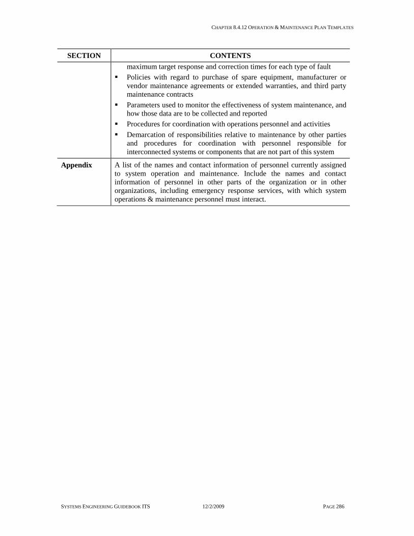
CHAPTER 8.4.12 OPERATION & MAINTENANCE PLAN TEMPLATES
SYSTEMS ENGINEERING GUIDEBOOK ITS 12/2/2009 PAGE 286
SECTION CONTENTS maximum target response and correction times for each type of fault
Policies with regard to purchase of spare equipment, manufacturer or vendor maintenance agreements or extended warranties, and third party maintenance contracts
Parameters used to monitor the effectiveness of system maintenance, and how those data are to be collected and reported
Procedures for coordination with operations personnel and activities Demarcation of responsibilities relative to maintenance by other parties
and procedures for coordination with personnel responsible for interconnected systems or components that are not part of this system
Appendix A list of the names and contact information of personnel currently assigned to system operation and maintenance. Include the names and contact information of personnel in other parts of the organization or in other organizations, including emergency response services, with which system operations & maintenance personnel must interact.
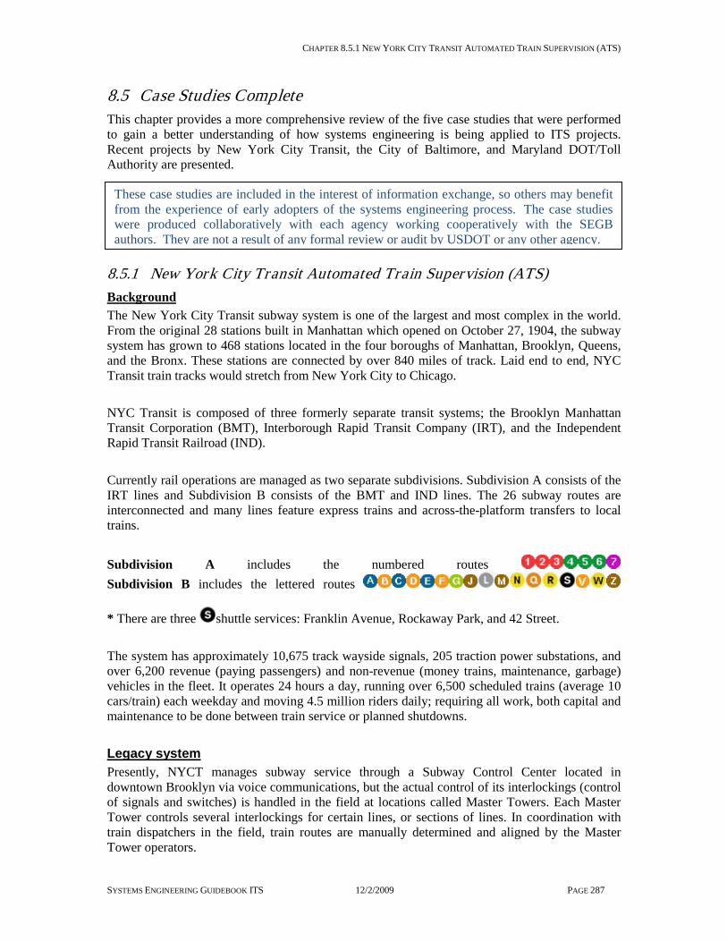
CHAPTER 8.5.1 NEW YORK CITY TRANSIT AUTOMATED TRAIN SUPERVISION (ATS)
SYSTEMS ENGINEERING GUIDEBOOK ITS 12/2/2009 PAGE 287
8.5 Case Studies Complete This chapter provides a more comprehensive review of the five case studies that were performed to gain a better understanding of how systems engineering is being applied to ITS projects. Recent projects by New York City Transit, the City of Baltimore, and Maryland DOT/Toll Authority are presented.
8.5.1 New York City Transit Automated Train Supervision (ATS) Background The New York City Transit subway system is one of the largest and most complex in the world. From the original 28 stations built in Manhattan which opened on October 27, 1904, the subway system has grown to 468 stations located in the four boroughs of Manhattan, Brooklyn, Queens, and the Bronx. These stations are connected by over 840 miles of track. Laid end to end, NYC Transit train tracks would stretch from New York City to Chicago. NYC Transit is composed of three formerly separate transit systems; the Brooklyn Manhattan Transit Corporation (BMT), Interborough Rapid Transit Company (IRT), and the Independent Rapid Transit Railroad (IND). Currently rail operations are managed as two separate subdivisions. Subdivision A consists of the IRT lines and Subdivision B consists of the BMT and IND lines. The 26 subway routes are interconnected and many lines feature express trains and across-the-platform transfers to local trains. Subdivision A includes the numbered routes Subdivision B includes the lettered routes * There are three shuttle services: Franklin Avenue, Rockaway Park, and 42 Street. The system has approximately 10,675 track wayside signals, 205 traction power substations, and over 6,200 revenue (paying passengers) and non-revenue (money trains, maintenance, garbage) vehicles in the fleet. It operates 24 hours a day, running over 6,500 scheduled trains (average 10 cars/train) each weekday and moving 4.5 million riders daily; requiring all work, both capital and maintenance to be done between train service or planned shutdowns. Legacy system Presently, NYCT manages subway service through a Subway Control Center located in downtown Brooklyn via voice communications, but the actual control of its interlockings (control of signals and switches) is handled in the field at locations called Master Towers. Each Master Tower controls several interlockings for certain lines, or sections of lines. In coordination with train dispatchers in the field, train routes are manually determined and aligned by the Master Tower operators.
These case studies are included in the interest of information exchange, so others may benefit from the experience of early adopters of the systems engineering process. The case studies were produced collaboratively with each agency working cooperatively with the SEGB authors. They are not a result of any formal review or audit by USDOT or any other agency.
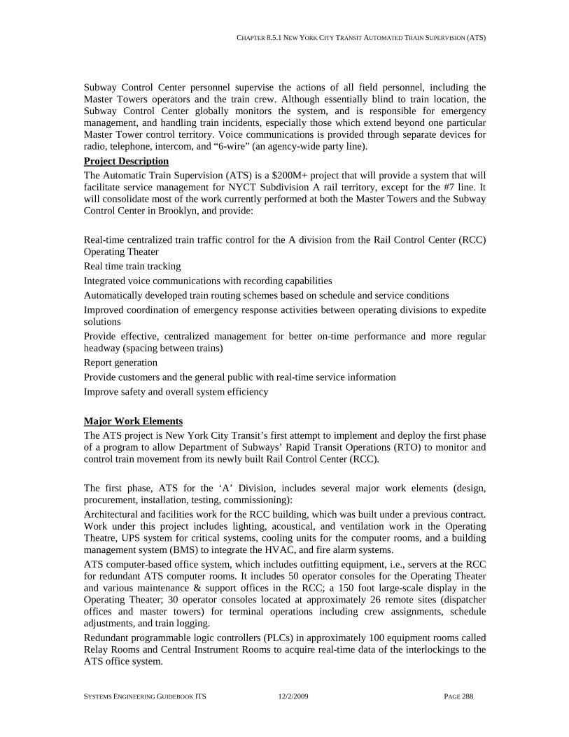
CHAPTER 8.5.1 NEW YORK CITY TRANSIT AUTOMATED TRAIN SUPERVISION (ATS)
SYSTEMS ENGINEERING GUIDEBOOK ITS 12/2/2009 PAGE 288
Subway Control Center personnel supervise the actions of all field personnel, including the Master Towers operators and the train crew. Although essentially blind to train location, the Subway Control Center globally monitors the system, and is responsible for emergency management, and handling train incidents, especially those which extend beyond one particular Master Tower control territory. Voice communications is provided through separate devices for radio, telephone, intercom, and “6-wire” (an agency-wide party line). Project Description The Automatic Train Supervision (ATS) is a $200M+ project that will provide a system that will facilitate service management for NYCT Subdivision A rail territory, except for the #7 line. It will consolidate most of the work currently performed at both the Master Towers and the Subway Control Center in Brooklyn, and provide: Real-time centralized train traffic control for the A division from the Rail Control Center (RCC) Operating Theater Real time train tracking Integrated voice communications with recording capabilities Automatically developed train routing schemes based on schedule and service conditions Improved coordination of emergency response activities between operating divisions to expedite solutions Provide effective, centralized management for better on-time performance and more regular headway (spacing between trains) Report generation Provide customers and the general public with real-time service information Improve safety and overall system efficiency Major Work Elements The ATS project is New York City Transit’s first attempt to implement and deploy the first phase of a program to allow Department of Subways’ Rapid Transit Operations (RTO) to monitor and control train movement from its newly built Rail Control Center (RCC). The first phase, ATS for the ‘A’ Division, includes several major work elements (design, procurement, installation, testing, commissioning): Architectural and facilities work for the RCC building, which was built under a previous contract. Work under this project includes lighting, acoustical, and ventilation work in the Operating Theatre, UPS system for critical systems, cooling units for the computer rooms, and a building management system (BMS) to integrate the HVAC, and fire alarm systems. ATS computer-based office system, which includes outfitting equipment, i.e., servers at the RCC for redundant ATS computer rooms. It includes 50 operator consoles for the Operating Theater and various maintenance & support offices in the RCC; a 150 foot large-scale display in the Operating Theater; 30 operator consoles located at approximately 26 remote sites (dispatcher offices and master towers) for terminal operations including crew assignments, schedule adjustments, and train logging. Redundant programmable logic controllers (PLCs) in approximately 100 equipment rooms called Relay Rooms and Central Instrument Rooms to acquire real-time data of the interlockings to the ATS office system.

CHAPTER 8.5.1 NEW YORK CITY TRANSIT AUTOMATED TRAIN SUPERVISION (ATS)
SYSTEMS ENGINEERING GUIDEBOOK ITS 12/2/2009 PAGE 289
Automatic Vehicle Identification (AVI) readers located on the tracks provide train identification and information to the ATS office system. Interfaces to several NYCT legacy systems to provide data for ATS reporting functions. An integrated communications switch (ICS) to consolidate telephone, radio and other NYCT legacy systems (train dispatch system and 6-wire) circuits, and allow an ATS operator the ability to communicate to all these systems through one headset and console display. The communications sub-system includes an automated attendant and a voice recording sub-system. Contract Documentation The ATS contract documents (drawings and specifications) are divided into various sections or ‘divisions’. Several of the divisions include the information regarding general requirements of the contract such as terms & conditions and special conditions. The remaining divisions include the requirements for each of the various design discipline areas. Each respective design group within NYCT developed their specific design discipline divisions of the contract and their associated drawings. A consulting firm developed the new ATS system functional requirements that became part of a new division of the specifications. Although there was an exhaustive effort to gather input from the end-user, RTO, and to develop system functional requirements for ATS, a documented list of user requirements and a Concept of Operations document were never developed for this project. The user requirements of other key stakeholders, such as network security and several maintenance organizations were also overlooked. In addition, the functional requirements for the voice communications sub-system are vaguely described in the contract documents as required to be “of similar functionality to what is currently available at the Command Center” in Brooklyn. There are no specific functional requirements detailed in the specifications for the voice communications sub-system, which has resulted in several disputes with the contractor during various phases of the project about what is really required to meet the users’ needs and expectations. Project Status As of February 2006, the ATS project is currently in the last stages of Implementation and Test. There are still several major software variances as well as several critical field issues that are outstanding and resolution of these items is necessary in order to run efficient and reliable service. In September 2005, NYCT moved RTO from the Brooklyn Command Center to the Rail Control Center in an attempt to utilize the voice communications sub-system and have the ATS operators gain experience and confidence with this system component. However, after 11 days in operation, the project experienced a major setback when the communications system failed due to a high volume of calls as a result of a combination of events - an attempted suicide on the tracks and a bomb scare on the Lexington line. RTO is still awaiting a return to the RCC, and there is significant pressure from the NYCT President and the MTA parent organization on the project team to resolve this system performance issue and complete the project. Contractor Joint Venture Team The ATS contract was awarded in November 1997 to a US-based signal company familiar with NYCT and its operations. They assumed responsibility for systems integration, the design and implementation of the signaling and communications work, and the Centralized Train Control (CTC) portion of the office software. The remaining software was the responsibility of a subcontractor who had previously performed a smaller computer-based train control project for NYCT on the 63rd Street connection. An electrical contractor was subcontracted to do the installation work both in the field and at the RCC. The project duration was initially set at 60

CHAPTER 8.5.1 NEW YORK CITY TRANSIT AUTOMATED TRAIN SUPERVISION (ATS)
SYSTEMS ENGINEERING GUIDEBOOK ITS 12/2/2009 PAGE 290
months. Despite 18 months of negotiations during the RFP phase, it was determined that the contractor’s software development team could not meet major functional requirements in the contract and there were concerns about the scalability of the system. The contractor was defaulted in 1999. NYCT then contracted with a Joint Venture (JV) team in September 2000 to complete the project. The newly structured JV consisted of the same signal company and electrical installer from the defaulted team. In the new contract agreement the signal company is only responsible for design, installation, and testing of the PLCs in the field. The new JV partner, a European software company assumed the lead in systems integration and overall software development. The selection of this software firm was based entirely on its established software platform used at other rail transit properties and had originally been developed for SCADA type applications. It would require customization for NYCT’s unique signal control functionality. The new contract was given a 48-month duration, the remaining time left from the original contract timeframe. This aggressive schedule was based in part on the determination that documentation from the original contract could be re-used. Unfortunately, the contract documents did not include an updated proposal from the new JV company. This led to many vague interpretations of what was expected throughout the project. The new JV lead also had no experience doing work for NYCT and was not familiar with its complex signaling system and Rapid Transit Operations. The lead JV partner maintains a NY based project management office responsible for system design and integration as well as hardware selection. Its software development team resides overseas, which poses several challenges related to coordination of project management and systems integration. Although from the same parent company, the managers of these two units report to two different principles within their organization. NYCT Project Team NYCT had limited experience in managing large systems projects, but made efforts to follow a disciplined approach to reviewing and approving contractor’s submittals and Contract Data Requirements List (CDRLs) by forming working group teams based on areas of responsibility. Working groups were established for Systems, Software, Software Process, RCC (for building issues), Signals, Test & Commissioning, and User (prototyping and training). Chairpersons of these working groups were NYCT personnel from various departments, and members of these groups had cross-functional representation. Additionally, NYCT’s own staff was augmented by engineering consultants, co-located in the construction manager’s office along with and in support of the Software working group lead, managing the requirements and functional testing of the systems division of the specifications. The construction manager’s office is part of a Program Area, which has field inspectors who have traditionally overseen work on conventional signal projects. Because of the complexity of the ATS system, which requires additional expertise in other areas, such as fiber optics and telecommunications work, this team has had difficulty in conducting inspections and are not familiar with the proper operating procedures and protocols required by the associated operations departments for access and protection and working on live equipment. A provision to have a communications engineer on the project or matrixed personnel from the operations department to perform contractor oversight for this work is being contemplated on the next phase of the ATS program. Additionally, there is a recent acknowledgment from NYCT management that NYCT may need to evaluate its current organizational structure for large systems projects. One option that is being proposed is to provide “systems engineers” resident in the construction manager’s

CHAPTER 8.5.1 NEW YORK CITY TRANSIT AUTOMATED TRAIN SUPERVISION (ATS)
SYSTEMS ENGINEERING GUIDEBOOK ITS 12/2/2009 PAGE 291
office to provide technical support to the construction manager in making more informed decisions with a systems perspective. Systems Engineering (SE) Management At the outset of this project there was no formal SE process or products considered. A specific Systems Engineering Management Plan (SEMP) was never developed for this project, which would have defined the formal SE project organization. However within the first year of the new contract, working relationships evolved into an informal team approach. Although the project team did not include all the project stakeholders, it consisted of a core group of representatives from the main design discipline areas, such as Signals and Software, and Rapid Transit Operations, the operational end-user of the system under development. On projects with less complexity, the project team members were able to be stove-piped in their approach. However, they learned that this project would require working in a team, to not only provide their specific domain knowledge but to also understand each other’s concerns and evaluate their decisions on the entire system as a whole. As a result the project team was able to overcome the lack of formal processes by their strong communications and their ability to reach consensus with their different perspectives in mind. Unfortunately, some decisions were made in haste; the team evaluation approach having been circumvented largely due to schedule pressures. Another issue was that existing NYCT-internal project management procedures and templates did not fully define a systems engineering approach to planning, designing, and implementing a capital project such as ATS. There are currently no steps within these procedures, for example, to explain the necessity to identify all the stakeholders of the system (including the system and equipment maintainers), how to capture and document a comprehensive set of user requirements, and the importance of developing a Concept of Operations. The procedures were written in the context of standard “brick and mortar” type projects. They do not address the need for interdisciplinary perspectives nor explain how to manage requirements that may affect multiple stakeholders. Efforts to Communicate NYCT-Specific Domain Knowledge The ATS contract required the contractor to be familiar with NYCT operations and its signaling system. Although the signal company and electrical installer had individuals who possessed this knowledge, the JV partner responsible for software development did not, and there was no specific contractual agreements between the partners to share these resources. NYCT had not conducted a formal qualifications evaluation of the new JV partner to assess its NYCT-specific domain knowledge. They had relied on their expectation that the required expertise would be provided by the contractor. As part of the contract deliverables, the contractor’s Signal Engineer, provided by the signal company, created an Interlocking Rules document that translated the general functionality of the signal system for the developers’ understanding and use in their design. However, an addendum to this document explaining the site-specific nuances of each particular interlockings was never developed. The generalized algorithms designed in response to the Interlocking Rules document in most cases were unable to support the varying inputs from the field. To overcome this deficiency, NYCT tried to supplement the information provided in the Interlocking Rules document by providing training to the software developers in NYCT operations, courses similar to those given to its own train operators. But it was evident that this knowledge could not be captured in such a short amount of time. NYCT was forced to provide the services of its own Signal Engineers to provide guidance and consultation to the contractor’s software development team in order to move the project forward.
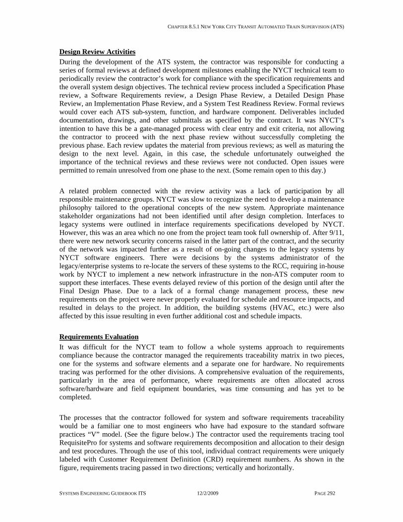
CHAPTER 8.5.1 NEW YORK CITY TRANSIT AUTOMATED TRAIN SUPERVISION (ATS)
SYSTEMS ENGINEERING GUIDEBOOK ITS 12/2/2009 PAGE 292
Design Review Activities During the development of the ATS system, the contractor was responsible for conducting a series of formal reviews at defined development milestones enabling the NYCT technical team to periodically review the contractor’s work for compliance with the specification requirements and the overall system design objectives. The technical review process included a Specification Phase review, a Software Requirements review, a Design Phase Review, a Detailed Design Phase Review, an Implementation Phase Review, and a System Test Readiness Review. Formal reviews would cover each ATS sub-system, function, and hardware component. Deliverables included documentation, drawings, and other submittals as specified by the contract. It was NYCT’s intention to have this be a gate-managed process with clear entry and exit criteria, not allowing the contractor to proceed with the next phase review without successfully completing the previous phase. Each review updates the material from previous reviews; as well as maturing the design to the next level. Again, in this case, the schedule unfortunately outweighed the importance of the technical reviews and these reviews were not conducted. Open issues were permitted to remain unresolved from one phase to the next. (Some remain open to this day.) A related problem connected with the review activity was a lack of participation by all responsible maintenance groups. NYCT was slow to recognize the need to develop a maintenance philosophy tailored to the operational concepts of the new system. Appropriate maintenance stakeholder organizations had not been identified until after design completion. Interfaces to legacy systems were outlined in interface requirements specifications developed by NYCT. However, this was an area which no one from the project team took full ownership of. After 9/11, there were new network security concerns raised in the latter part of the contract, and the security of the network was impacted further as a result of on-going changes to the legacy systems by NYCT software engineers. There were decisions by the systems administrator of the legacy/enterprise systems to re-locate the servers of these systems to the RCC, requiring in-house work by NYCT to implement a new network infrastructure in the non-ATS computer room to support these interfaces. These events delayed review of this portion of the design until after the Final Design Phase. Due to a lack of a formal change management process, these new requirements on the project were never properly evaluated for schedule and resource impacts, and resulted in delays to the project. In addition, the building systems (HVAC, etc.) were also affected by this issue resulting in even further additional cost and schedule impacts. Requirements Evaluation It was difficult for the NYCT team to follow a whole systems approach to requirements compliance because the contractor managed the requirements traceability matrix in two pieces, one for the systems and software elements and a separate one for hardware. No requirements tracing was performed for the other divisions. A comprehensive evaluation of the requirements, particularly in the area of performance, where requirements are often allocated across software/hardware and field equipment boundaries, was time consuming and has yet to be completed. The processes that the contractor followed for system and software requirements traceability would be a familiar one to most engineers who have had exposure to the standard software practices “V” model. (See the figure below.) The contractor used the requirements tracing tool RequisitePro for systems and software requirements decomposition and allocation to their design and test procedures. Through the use of this tool, individual contract requirements were uniquely labeled with Customer Requirement Definition (CRD) requirement numbers. As shown in the figure, requirements tracing passed in two directions; vertically and horizontally.

CHAPTER 8.5.1 NEW YORK CITY TRANSIT AUTOMATED TRAIN SUPERVISION (ATS)
SYSTEMS ENGINEERING GUIDEBOOK ITS 12/2/2009 PAGE 293
SoftwareDesign
SoftwareDetailed Design
SoftwareImplementation
Software TestRequirementsCRD
FEAT
SoftwareSystem Test
DE
Module
SoftwareDesign
SoftwareDetailed Design
SoftwareImplementation
Vertical Tracing
SoftwareSystem Test
SoftwareRequirements
SoftwareRequirements
Software TestRequirementsHorizontal Tracing
SoftwareModule Test
TEST
VAL
TEST
VAL
Figure 8-2– NYCT ATS Software Requirements Traceability
The vertical tracing connected each ‘CRD’ to a Software Functional Requirements Document (SFRD) feature (FEAT). The FEATs then traced to a Design Element (DE) in the design document and then to individual software modules. The horizontal path directly connects CRDs to verification Test Cases. While there was no equivalent formal traceability done for requirements listed in the contract for other divisions, oversight for these areas was fortunately familiar ground to each responsible NYCT organization. NYCT has extensive experience managing infrastructure and signaling type contracts and these projects have been commissioned successfully by relying heavily on resident expertise for inspections and document & drawing reviews. Contract compliance oversight in these cases was continuous but undocumented. The verification of the hardware section of the specifications followed a process that has elements of both of the above methods. The contractor had developed a manually generated Requirements Traceability Matrix for the ATS office hardware. This was used primarily as a reference by the responsible NYCT systems organization during the project development. Much of the compliance verification in the case of office hardware focused on review of Commercial-Off-The-Shelf (COTS) equipment catalog cuts. A major challenge faced by the NYCT team regarding requirements verification activities was a clash in the “corporate culture” between the software engineers who were familiar with standard software development processes and those who were more accustomed to the “reliance of domain experts” used in past projects. Management, who generally fell into the latter category, remained unconvinced of the usefulness of what seemed to them an endless review process in the early requirements and design stages. They had the perception that this activity was holding up their job. Oversight trips to the contractor location for process and development audit purposes were not taken partly as an attempt to shorten these development activities and contributed to phase transition reviews becoming virtual milestones rather than real ones.

CHAPTER 8.5.1 NEW YORK CITY TRANSIT AUTOMATED TRAIN SUPERVISION (ATS)
SYSTEMS ENGINEERING GUIDEBOOK ITS 12/2/2009 PAGE 294
Prototyping Phase Prototyping for this project primarily focused on on-screen dialog and on display content and appearance. Dialogs provide the user interface for train control, scheduling, and configuration. Displays allow the user to monitor train and system status. Reports that were traditionally typed were included which would allow for manual semi-automatic (e.g. through selection lists) and automatic (i.e. system database provided) entry. Initial plans were to prototype these screens on actual user console configurations. However, in order to shorten this development phase, NYCT allowed the contractor to submit individual screens shots that were depicted only from power-point presentation images. Usability issues such as navigating through multiple screens were difficult to evaluate using this method. Without the use of a more sophisticated prototyping tool, the dynamic aspects of GUI interactions were difficult to capture. Once submitted, the prototype team, made up of engineering and user representatives, discussed and provided comments. A second conference was then held with the contractor where agreements were reached on changes. The figure below represents a typical example of a result of the discussions and agreements, as outlined in the Prototype Comment Report (PCR). Each prototype comment was given a unique PCR number, description and status.
PCR no. Title Subtitle/info NYCT Comment Status
768 Performance Reports
Train Sheet Performance Report
Train Sheet Performance Report: clarify if the report is filterable only by individual lines (services) or also by multiple services.
15may02: Contractor - will PROT2.2.12.2provide capability to select multiple services for performance reports .
Figure 8-3 – NYCT ATS Prototype Agreement Example
The final system suffered from the exclusive use of the PowerPoint presentations for Prototyping. Inter-operability and user experience scenarios were untried prior to Factory Acceptance Test. This led to a design that while meeting the contract requirements is sometimes awkward to use. When a concern became serious enough, it forced NYCT to issue Additional Work Orders (AWOs) to the contractor in order to correct the problem, adding to the project’s schedule and cost. Another issue concerning prototyping was with how the contractor handled the tracing of prototype agreements. These were not handled in the same manner as requirements in that they were not traced horizontally directly to test procedures. The figure below, provided by the contractor showing their concept for traceability, illustrates this.

CHAPTER 8.5.1 NEW YORK CITY TRANSIT AUTOMATED TRAIN SUPERVISION (ATS)
SYSTEMS ENGINEERING GUIDEBOOK ITS 12/2/2009 PAGE 295
Software FunctionalRequirements Specification
Software DesignDocuments
(DE‘s)
Test Procedures
Module TestProcedures
(TEST‘s)
CRD = Customer Requirement Definition
FEAT = System Feature
DE = Design Element
TEST = Test Requirement
PROTO = Prototype Requirement
Software FunctionalRequirements Specification
Software DesignDocuments
(DE‘s)
Test Procedures
Module TestProcedures
(TEST‘s)
CRD = Customer Requirement Definition
FEAT = System Feature
DE = Design Element
TEST = Test Requirement
PROTO = Prototype Requirement
ContractRequirementsSpecification
(CRD’s)
TestRequirementsTestRequirements
SoftwareSpecificationRequirements
SoftwareSpecificationRequirements
Software DesignRequirementsSoftware DesignRequirements
SoftwareDesignRequirements
SoftwareDesignRequirements
TestRequirementsTestRequirements
PrototypeRequirementsPrototypeRequirements
TestRequirementsTestRequirements
(PROTO‘s)(PROTO‘s)
Train Control Functions & AlgorithmPrototypesTrain Control Functions & AlgorithmPrototypes
User Interface Prototype DocumentUser Interface Prototype Document
(FEAT‘s)(FEAT‘s)
(TEST‘s)(TEST‘s)
Figure 8-4– NYCT ATS Prototype Traceability
The contractor maintained that all prototype agreements would be kept because they would be addressed by the design and the design would then be tested. However this assertion depended entirely on the quality of the design documents. In many cases the design documents did not include sufficient detail to include this prototyping information. The development of test procedures that addressed verification of prototyping agreement specifics was even more unlikely. The records from the initial prototyping agreements developed by the prototyping team ultimately proved to be an invaluable asset in assuring prototype compliance. Prototyping of the voice communications Graphical User Interface (GUI) was not done. To compensate for the limited detail in the contract specifications, and the contractor’s lack of knowledge of RTO’s operational needs, NYCT spent several weeks jointly developing the GUI screens with the contractor for the new sub-system. Testing Activities NYCT did not feel it was necessary to closely monitor and audit the contractor’s software development progress, and only visited their overseas software facility once prior to the Factory Acceptance Test (FAT). Despite suggestions from the contractor that an NYCT engineer reside at their facility during the software development cycle, NYCT management felt that the potential benefit over other methods of technical exchanges was not worth the added cost. As required by contract, the JV submitted a FAT readiness certification letter attaching their Pre-FAT test results. The letter was received just days before the NYCT test team was to depart for FAT overseas and a quick review of the Pre-FAT results revealed significant remaining functional deficiencies. Additionally, during FAT, it was discovered that the developers did not have the basic understanding of NYCT’s signaling system and had misinterpreted how certain functions were to operate. In order to avoid additional schedule slips, following this discovery that the contractor had not progressed as far along as status reports had indicated, NYCT provided full time support of their own signal engineers to the project. Two signal engineers stayed

CHAPTER 8.5.1 NEW YORK CITY TRANSIT AUTOMATED TRAIN SUPERVISION (ATS)
SYSTEMS ENGINEERING GUIDEBOOK ITS 12/2/2009 PAGE 296
overseas for 6-month duration to assist the contractor in re-design efforts resulting in unanticipated costs to NYCT. As per the approved software planning documentation, the contractor had an independent test team responsible for the supervision and execution of software test activities. Although ultimately reporting to the same management, this independency was more a distinction of this team’s focus when compared to the primary goals of the development team. For FAT and field performance testing, this team developed the test procedures, and documented and tracked the resolution of variances found during tests. Clear Quest was used to monitor testing progress and allowed the developers, testers, and NYCT the ability to evaluate the latest variance status. A strategy of phasing Field Performance Testing (FPT) in parallel with FAT was developed jointly between NYCT and the contractor, and interim software development milestones were defined. For several months, NYCT had a test team at the contractor’s software facility performing FAT while another team began FPT in NY. Also, several FAT activities were conducted in NY on the training system. This posed a challenge for configuration management, keeping track of software and database versions for the test system overseas, the training system in NY, and the actual operating system at the RCC. The contractor was given permission to have a remote connection at the Rail Control Center to provide for easy downloads of software releases from the development team. This line was open and unmonitored and allowed the contractor to easily make updates to both the ATS office software, front-end application logic, and database without first notifying NYCT. Several times during operational tests, problems were encountered because changes were not properly documented which ultimately resulted in delays in train service. Another issue that arose during field-testing of the ATS office software was the contractor’s inability to provide a realistic test schedule. Schedules were always best case, developed with little contingency planning, and were often useless after the first missed event. Testing of the voice communications sub-system was the responsibility of the communications integrator, with little oversight by the lead JV partner, who had responsibility for systems engineering/integration. Although systems integration testing of ATS and voice communications was required in a factory setting with simulation, this requirement was not strictly enforced under the project’s schedule constraints and the contractor was allowed to conduct these tests on site at the RCC. As a result, a myriad of problems that could have been detected easily in the factory took more time to detect and troubleshoot given the conditions of operating with live circuits on an operating railroad. Contractor Developed Training The contract required a Training Program for both the ATS operators to learn how to operate the system, and for the maintainers (both software and hardware) to maintain the system. This program was to be developed as a train-the-trainer, and gave the contractor the option to include OEM courses from third party providers. The contractor utilized its subsidiary unit to develop the ATS dispatcher course. Although the instructor was familiar with the generic SCADA-based software package that formed the basis of the ATS software, the instructor lacked knowledge of the ATS system and did not have experience in NYCT operations. The instructor had not spent anytime overseas and had little

CHAPTER 8.5.1 NEW YORK CITY TRANSIT AUTOMATED TRAIN SUPERVISION (ATS)
SYSTEMS ENGINEERING GUIDEBOOK ITS 12/2/2009 PAGE 297
contact with the development team. Training documents were developed before the completion of FAT, and were not updated each time the software was revised. The training was a 10-day course and it was difficult to develop a training schedule given the continual delay in FAT completion and the requirement to train the users within a 6-month window prior to the initiation of actual system operation. Since NYCT had not foreseen the importance of having the RTO instructors participate in the FAT, they had difficulty working with the contractor to develop the coursework to train the operators. They could not explain the differences between the current operations and operations conceptualized with the new system. There was no formal mechanism to alert the instructors to changes that were being made on the training system. During field performance testing, which requires support from 10-20 trained ATS operators, a challenge for the test team was supplying enough ATS operators to perform required testing. Many of the problems encountered during testing were found to be operator-error. The courses designed for hardware maintenance were a compilation of various OEM courses that did not contain any project specific information about the system that was being implemented. Courses were not tailored to the appropriate maintenance groups, and the large number of courses, many with other courses as prerequisites, was a constant strain on NYCT resources. Coordination of the training courses was not handled by NYCT’s Employee Development and Training division, but by the Construction Manager’s office that had difficulty ensuring that the right individuals were attending the right courses. The software and database maintenance courses provided by the JV lead were generic versions utilized on the SCADA projects. The level of detail included in the manuals to explain the customized parts of the software were not what was expected. There were disputes regarding the definition of “software maintenance” and what tasks were associated with this term. After an initial pass of the software maintenance courses with a core NYCT team, it was determined that these courses were not at an appropriate level to expect NYCT to assume responsibility for maintenance. NYCT initiated its option in the contract to negotiate a maintenance contract with the contractor for a 3-year period at additional expense. NYCT was also remiss in staffing personnel who were proficient in software coding at the beginning of the project in order to understand maintenance of the new system post delivery.

CHAPTER 8.5.1 NEW YORK CITY TRANSIT AUTOMATED TRAIN SUPERVISION (ATS)
SYSTEMS ENGINEERING GUIDEBOOK ITS 12/2/2009 PAGE 298
Major Process Lessons Learned The ATS-A NYCT team has jointly developed lessons learned. This activity takes on a greater importance due to the follow-up plans for the second phase of this project on Subdivision ‘B’. Lessons learned related to this case study are listed below.
Table 8-1 NYCT ATS Lessons Learned
Improvement for ATS-B Impact to ATS-A Prototyping should be demonstrated on an actual workstation mock-up
Future users did not have a clear understanding of screen interactions when only evaluating individual presentation screens. Workstation workspace was purposely planned to be tailor-able to an individual’s preferences therefore a “typical” screen layout could not evaluated for usability.
Prototype agreements should clearly be identified following the criteria for requirements: unambiguous, unique, and testable. They should be tracked as supplemental contract requirements
ATS-A prototype agreements were embedded in “discussions”. The contractor tracked them to the design documents that lacked the appropriate detail to address these issues. Much effort was spent by NYCT to make sure that agreements were not bypassed during acceptance test.
Independent Contractor Test Team – Confirm adequate coverage in specification to assure this standard development process protocol.
The independent test team (i.e. sole responsibilities are testing and taking/re-checking variances) slowly disintegrated. Only developers remained. In addition to the conflict of issues problem is: Developers seldom know more than their own area well; not the whole system. Developers also typically feel testing is not part of their job. Time spent by developers testing impacts project schedule because variances are not being corrected.
Design Document updates – When design is altered or more detail is added due to prototype, variances, AWOs etc. A new release is not expected, however the working copy of the design document should be modified and available on-line
As implementation and testing progresses, the design documents are further and further from reality. Other SOWs, letters of direction, memos and Emails constitute the actual design. Every change such as this should include an equivalent documentation update; the release letter should identify which documents are affected.
Design Review milestones should be taken seriously and successful completion should be a prerequisite for proceeding to the next review phase.
No time was saved by accepting virtual milestones; rather time was lost in later phases of the project for longer durations.
An NYCT Integrated Project Team should be formed and dedicated to support the Construction Manager
Inappropriate skills and competencies of personnel resulted in the wrong individuals inspecting, testing and accepting equipment/systems; Construction Manager was forced to make decisions without the right technical support.
Change Control Board – Should be instituted early in the process and include NYCT involvement.
The requirements were never truly “base-lined”, which posed difficulty to the project team to assess necessary changes. Without a formal change process through a Change Control Board many decisions were made by management without careful evaluation of the impacts to the entire system, and the associated risks to the project.
Requirements Traceability Tool should be utilized from a “systems” perspective.
Traceability of system performance requirements is time consuming and has yet to be completed.
Need to have a Systems Engineering Management Plan to define roles & responsibilities of the project team
Although working groups were established, discipline engineers still had a tendency to work with a stove-piped approach to design and implementation of their specific sub-systems.
Operator training needs to be conducted early enough in the project to provide available and qualified resources to support testing activities.
Mismatch of qualified testers during critical phases of site-acceptance testing; Delays to project schedule also resulted in operations staff having to be re-trained.

CHAPTER 8.5.2 BALTIMORE INTEGRATED TRAFFIC MANAGEMENT SYSTEM
SYSTEMS ENGINEERING GUIDEBOOK ITS 12/2/2009 PAGE 299
8.5.2 Baltimore Integrated Traffic Management System System Description The City of Baltimore Integrated Traffic Management System is a major upgrade of the City of Baltimore’s street traffic management system. It involved replacement of all traffic signal controllers and cabinets, installation of additional closed circuit television cameras, upgrading and expansion of center-to-field communications infrastructure, video exchange with CHART, a new traffic management center, new central computer hardware and software for remote management of field devices, and updated traffic signal timings. The $26 million project provides Baltimore, Maryland, with a state-of-the-art traffic management system that provides many capabilities missing from the previous system. These new capabilities include:
• NEMA TS2 functions added to all traffic signal controllers (replacement of 1970s era pre-NEMA controllers and cabinets, new signal timings, automatic fallback to controller-based time-of-day timing plan selection).
• Support for additional traffic control strategies such as traffic responsive and traffic adaptive.
• Integration of signal control along the Howard St light rail corridor provides support for light rail transit priority
• Ability to choose future traffic signal controllers from multiple vendors (NTCIP standard communications protocol).
• 300 additional traffic signals able to be remotely monitored and managed (new communications cable and modems, and upgraded communications hubs).
• 100 intersections able to be visually monitored from the traffic management center (new CCTV cameras).
• Numerous additional functions available to operators at the traffic management center (new TMC, new central software, new graphical user interface, asset management software).
• Remote monitoring and management of field devices, including viewing of live video from CCTV cameras, available to more City personnel from more locations (link to City computer network, additional remote workstations, fiber optic cable between TMC and Signal Shop, web-browser-based access via the Internet).
• Ability to view live video from freeway cameras owned by Maryland DOT, and ability to make City camera feeds available to State traffic management personnel (two-way inter-agency video exchange via fiber optic link to Maryland Stadium Authority and hence to Maryland CHART).
• Ability to monitor vehicle flow and incident information along Maryland DOT freeways via a standalone CHART workstation located in the City of Baltimore TMC.
Together, these new capabilities enable more efficient and safer traffic signal operation, faster and more effective response to disruptive incidents, reduced system maintenance costs, and opportunities to further enhance traffic management in the future by measures such as automated traffic counting, traffic responsive signal timing plan selection, and adaptive traffic signal timing.

CHAPTER 8.5.2 BALTIMORE INTEGRATED TRAFFIC MANAGEMENT SYSTEM
SYSTEMS ENGINEERING GUIDEBOOK ITS 12/2/2009 PAGE 300
Involved Agencies and Their Roles The City of Baltimore, via its Department of Transportation, was the system owner and dominant stakeholder. The Maryland DOT (CHART) and Maryland Stadium Authority were involved by virtue of a two-way video and traffic data link between the new Baltimore traffic management system and existing Stadium Authority traffic operations centers at the M&T Ravens Stadium and Orioles Park at Camden Yards. These operations centers had existing communication links to Maryland CHART thus also providing a path for video and traffic data exchange between CHART and the City traffic management system. Inter-agency operational coordination was further enhanced by provision of a CHART workstation at the City traffic management center. The Federal Highway Administration played an important role in administering funds including timely approval of time-and-materials work orders. Contractors and Their Roles and How Selected The following table summarizes the various contracts used to implement the Baltimore Integrated Traffic Management System.
Contract Contracting Party
Procurement Method Contract Overseer
Program Management (including design)
City of Baltimore
Professional Services (RFP)
City of Baltimore DOT
Field Construction (including controller and cabinet installation)
City of Baltimore
Low-bid Program Management Contractor
System Integration City of Baltimore
Professional Services (Prequalification, RFP)
Program Management Contractor
TMC Architectural Design City of Baltimore
Professional Services (RFP)
Program Management Contractor
TMC Construction City of Baltimore
Low-bid Program Management Contractor
Signal Timing Optimization City of Baltimore
Professional Services (RFP)
City of Baltimore DOT
A feature of the City’s approach to contracting for this project is the degree of flexibility built into contracts. In particular, the program management contract with Sabra, Wang & Associates allowed for refinement of tasks and addition of tasks in response to unforeseen conditions. For example, project funding became available in multiple allocations, some at quite short notice, and the nature and extent of later-stage work was not fully known until after major components were selected during earlier stages. The system integration contract allowed for some design-build elements and loosely-defined later tasks that were refined as conditions and needs became clearer during system development. Such flexibility allowed a relatively large project to be implemented quickly and continuously with minimal administrative effort on the part of City personnel, while retaining the flexibility the City needed to adapt to evolving funding and technical conditions.

CHAPTER 8.5.2 BALTIMORE INTEGRATED TRAFFIC MANAGEMENT SYSTEM
SYSTEMS ENGINEERING GUIDEBOOK ITS 12/2/2009 PAGE 301
Agencies’ Previous Systems Engineering Experience and Capabilities Involved City of Baltimore personnel had very little experience in projects like this and little prior experience with systems engineering. The prior traffic signal management system was installed in 1976 and underwent only one significant upgrade, which replaced a mainframe computer with a minicomputer in 1994. Systems Engineering Management Planning No formal systems engineering planning was conducted. However, the program management and system integration contractors were familiar with systems engineering and used sound practices despite the lack of explicit planning. Most of the major systems engineering processes were included and documented, as summarized in the attached table titled Summary of Systems Engineering Activities Undertaken in Development of the Baltimore Integrated Traffic Management System. Comments on the Overall Experience The Baltimore Integrated Traffic Management System project is successful and is achieving its goals. Although the City did not plan for or require use of the formal systems engineering process, the contractors involved were accustomed to using systems engineering and knew it was necessary for a successful project. The contractors used the systems engineering process. Use of the NTCIP communications standard for traffic signals was key to the project’s success. The central signal management software and traffic signal controllers are from different manufacturers and had not been previously integrated. Integration went relatively smoothly largely because both the central software and the controllers supported the NTCIP communications standard for traffic signals. The integration effort revealed some inconsistencies in the respective implementations of NTCIP, but these were easily corrected. The City now is able to procure controllers from multiple NTCIP-compliant manufacturers. If the City wishes to use features not directly supported by the NTCIP standard, the standard provides a convenient mechanism for adding manufacturer-specific objects or data elements to any message, including the once-per-second status message. Due to its low bandwidth overhead, NTCIP’s “dynamic objects” feature allowed re-use of the existing City-owned twisted wire pair cable network. The project was not without its surprises and challenges. The following are some examples:
• It took six months to reach a resolution and agreement on the licensing rights between the system integrator and the local controller vendor. Many of the required MIBs in the local controller software are proprietary, and the vendor requested non-competing and copyright provisions prior to releasing the MIBs for the central system integration.
• The central software integrator had to perform regression testing against eleven different versions of the controller software.
• The 20-30 year old twisted wire pair cable was found to be deteriorated in several segments and problems became more apparent when the new high-speed modems were first used during the cutover process (broken pairs, noise voltage on the line, old/brittle insulation, crossed-pairs, use of non-twisted pairs, etc.). The controller
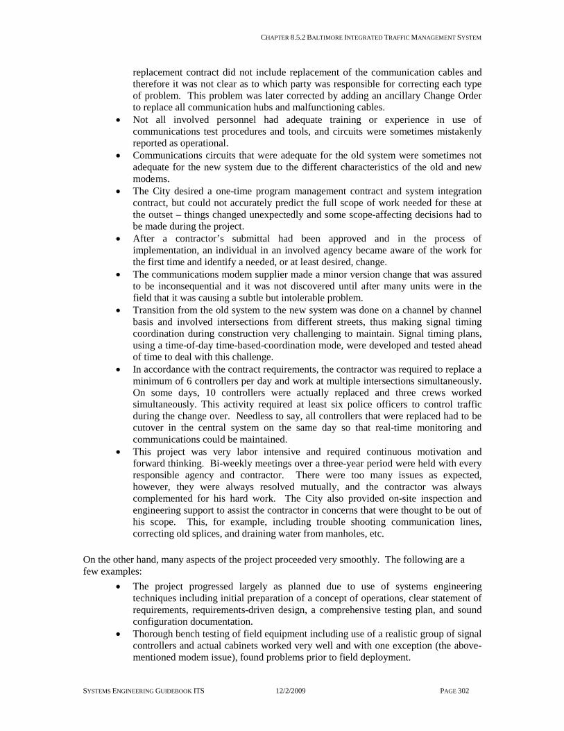
CHAPTER 8.5.2 BALTIMORE INTEGRATED TRAFFIC MANAGEMENT SYSTEM
SYSTEMS ENGINEERING GUIDEBOOK ITS 12/2/2009 PAGE 302
replacement contract did not include replacement of the communication cables and therefore it was not clear as to which party was responsible for correcting each type of problem. This problem was later corrected by adding an ancillary Change Order to replace all communication hubs and malfunctioning cables.
• Not all involved personnel had adequate training or experience in use of communications test procedures and tools, and circuits were sometimes mistakenly reported as operational.
• Communications circuits that were adequate for the old system were sometimes not adequate for the new system due to the different characteristics of the old and new modems.
• The City desired a one-time program management contract and system integration contract, but could not accurately predict the full scope of work needed for these at the outset – things changed unexpectedly and some scope-affecting decisions had to be made during the project.
• After a contractor’s submittal had been approved and in the process of implementation, an individual in an involved agency became aware of the work for the first time and identify a needed, or at least desired, change.
• The communications modem supplier made a minor version change that was assured to be inconsequential and it was not discovered until after many units were in the field that it was causing a subtle but intolerable problem.
• Transition from the old system to the new system was done on a channel by channel basis and involved intersections from different streets, thus making signal timing coordination during construction very challenging to maintain. Signal timing plans, using a time-of-day time-based-coordination mode, were developed and tested ahead of time to deal with this challenge.
• In accordance with the contract requirements, the contractor was required to replace a minimum of 6 controllers per day and work at multiple intersections simultaneously. On some days, 10 controllers were actually replaced and three crews worked simultaneously. This activity required at least six police officers to control traffic during the change over. Needless to say, all controllers that were replaced had to be cutover in the central system on the same day so that real-time monitoring and communications could be maintained.
• This project was very labor intensive and required continuous motivation and forward thinking. Bi-weekly meetings over a three-year period were held with every responsible agency and contractor. There were too many issues as expected, however, they were always resolved mutually, and the contractor was always complemented for his hard work. The City also provided on-site inspection and engineering support to assist the contractor in concerns that were thought to be out of his scope. This, for example, including trouble shooting communication lines, correcting old splices, and draining water from manholes, etc.
On the other hand, many aspects of the project proceeded very smoothly. The following are a few examples:
• The project progressed largely as planned due to use of systems engineering techniques including initial preparation of a concept of operations, clear statement of requirements, requirements-driven design, a comprehensive testing plan, and sound configuration documentation.
• Thorough bench testing of field equipment including use of a realistic group of signal controllers and actual cabinets worked very well and with one exception (the above-mentioned modem issue), found problems prior to field deployment.

CHAPTER 8.5.2 BALTIMORE INTEGRATED TRAFFIC MANAGEMENT SYSTEM
SYSTEMS ENGINEERING GUIDEBOOK ITS 12/2/2009 PAGE 303
• Frequent incremental testing during system integration and involvement of City personnel in those tests helped build and maintain confidence on the part of all parties and enabled
• Use of the NTCIP communications standard facilitated controller integration as discussed above.
• Good status and configuration documentation (e.g., hardware and software state, activities log, problem tracker, etc.) made it easy to measure progress, make changes when needed, and stay focused on outstanding problems.
• A well planned and methodical approach to cutover of communication circuits from old to new controllers helped that process proceed efficiently.
• An experienced program management consultant helped greatly in keeping the project on track and dealing with unexpected problems as they arose.
• The project was completed on-time and under budget. The Key Lessons Learned from the Baltimore Integrated TMS Project Use of an experienced program manager and the systems engineering process enabled a complex project to be successful. Flexible contracts with the program manager and system integrator enabled the contracts to be changed midstream to accommodate unforeseen or changed conditions. Use of the NTCIP communications standard was key to enabling integration of central software and field equipment from different manufacturers, and in giving the City the option to purchase future field equipment from different manufacturers. Thorough and realistic testing at every stage of system implementation, involving the owning agency in testing, and testing every change no matter how small and seemingly inconsequential, helps with progress monitoring and avoids expensive and time consuming field retrofits. Contractor submittals should include a signatures page that all concerned personnel must sign before work can proceed. This ensures the document has been reviewed and approved by all interested parties. Use of old equipment can lead to unforeseen problems that need to be accommodated. Facilities that work fine with an existing system may not be adequate for the new system with its different characteristics. Contracts should clearly delineate boundaries of responsibilities between the involved parties. Adequate training of all involved personnel is important, especially when new technology is being used or existing technology is being used in a new way. A carefully planned and methodical cut-over plan can add to the efficiency of changing over from old to new equipment.

CHAPTER 8.5.2 BALTIMORE INTEGRATED TRAFFIC MANAGEMENT SYSTEM
SYSTEMS ENGINEERING GUIDEBOOK ITS 12/2/2009 PAGE 304
Acknowledgement Ziad Sabra, Principal of Sabra, Wang & Associates, generously contributed his time for interviews, and contributed much of the information collected for this case study. Sabra, Wang & Associates is the program manager.

CHAPTER 8.5.2 BALTIMORE INTEGRATED TRAFFIC MANAGEMENT SYSTEM
SYSTEMS ENGINEERING GUIDEBOOK ITS 12/2/2009 PAGE 305
Table 8-2 Summary - Baltimore Integrated TMS Systems Engineer ing Activities by project phase Process Task Process Used Documents Produced Agency Effort
Expended Explanation, Issues, Problems, Lessons Learned
Feasibility No formal feasibility study.
Informal notes and meeting minutes only.
Low
Planning Technical memoranda discussed controller options, architecture options, and communications options. Meetings were held with CHART and Stadium Authority to determine the needed linkages between the systems, but no formal documentation.
Various technical memoranda.
Low Program Management contractor helped the City with system planning. Time and materials contract with task orders was critical to allowing contractor work to vary as needs were identified.
Concept of Operations Concept of operations documented at start of design.
Concept of Operations Low Helped by fact that the City already operated a traffic signal management system.
Validation Plan Planned to conduct travel time surveys before and after system implementation.
Plan not formally documented.
Low Included before-and-after studies.
System Requirements Identified during high level design. Documented within procurement specifications.
Med Program management contractor worked with City personnel to identify requirements. Prescriptive (specifications) for most field hardware, but kept as functional requirements where possible.
System Verification Plan Developed at start of system design. Documented in the system integration services contract.
Med
High Level Design Sub-system Requirements and Verification Plans
Part of design. Documented within procurement specifications – functional specs.
Med
Component Level Design Done by system integration contractor.
Hardware Selection, Software Design, System Configuration, Graphics Design
Low
Hardware and Software Development
Off-the-shelf hardware and software, with some central software enhancements.
Updates of above documents to reflect “as built”.
Low NTCIP very helpful in integrating field devices with central software.

CHAPTER 8.5.2 BALTIMORE INTEGRATED TRAFFIC MANAGEMENT SYSTEM
SYSTEMS ENGINEERING GUIDEBOOK ITS 12/2/2009 PAGE 306
Process Task Process Used Documents Produced Agency Effort Expended
Explanation, Issues, Problems, Lessons Learned
Unit Verification Individual pieces of field equipment were inspected by Program Manager upon installation. Controller software was bench tested by the System Integrator. Computer hardware units were tested by the System Integrator. Controllers and modems tested prior to installation.
Inspection and test reports. Med City personnel involved in review and testing of new signal controllers and cabinets.
Unit Integration Performed by the System Integrator. First draft of system configuration documents.
Low
Sub-system Verification Sub-systems were center-to-field communications, traffic signals, CCTV, DMS, TMC display equipment.
Test reports. High Central software replicated with number of field equipment units for system integrator bench testing at the Signal Shop. Used for acceptance testing too. City personnel involved in review and testing of communications sub-system.
Sub-system Integration Performed by the System Integrator. Updated system configuration documents.
Low Groups of signals were brought on line one at a time and tested individually.
System Verification Final integrated system acceptance testing performed by the system integrator and witnessed by the program manager and the system owner.
Acceptance Tests Med
Deployment Cutover to the new system progressed one communications circuit at a time.
Implementation Plan High
Validation Before and after study using travel time surveys.
Before and After Travel Time Survey
Low
Operations and Maintenance
TMC staffing needs were identified. TMC Staffing Plan High
Changes and Upgrades Some future system enhancements have been anticipated and allowed for in system design.

CHAPTER 8.5.3 MARYLAND CHART PROJECT
Systems Engineering Guidebook for ITS 12/2/2009 PAGE 307
8.5.3 Maryland Char t Project Maryland CHART – Systems Engineering Case Study System Description CHART (Coordinated Highways Action Response Team) is primarily an incident management system for roadways in Maryland. CHART is a joint effort of the Maryland Department of Transportation, Maryland Transportation Authority (toll authority) and the Maryland State Police, in cooperation with other federal, state and local agencies. CHART's mission is to improve "real-time" operations of Maryland's highway system through teamwork and technology. The CHART program relies on communication, coordination, and cooperation among agencies and disciplines, both within Maryland and with neighboring jurisdictions, to foster the teamwork necessary to achieve this goal. The CHART vision is comprised of four major categories of business objectives: 1. CHART is intended to be a statewide traffic management system, not limited to one or two specific corridors of high traffic volumes, but expandable to cover the entire state as funds, resources, and roadside equipment become available to support traffic management. 2. CHART is intended to be a coordination focal point, able to identify incidents, congestion, construction, road closures and other emergency conditions; and then able to direct the resources from various agencies, as necessary, to respond to recurring and nonrecurring congestion and emergencies. It should also manage traffic flow with traveler advisories and signal controls, and coordinate or aid in the cleanup and clearance of obstructions. 3. CHART is intended to be an information provider, providing real-time traffic flow and road condition information to travelers and the media broadcasters, as well as providing real-time and archived data to other state agencies and local, regional, inter-state, and private sector partners. 4. CHART is intended to be a 7 day per week, 24 hours per day operation with the system performing internal processing and status checks to detect failed system components and resetting or reconfiguring itself where appropriate, or notifying operators and/or maintenance staff where necessary for service. The system being described here is actually the second version of the original CHART system, and is technically called CHART II. The first CHART system was the first major ITS project undertaken by the stakeholders, and that experience helped greatly when it came to the system replacement project. In particular, it clearly identified the need for more careful planning and sound systems engineering in developing large traffic management systems. Unless stated otherwise, all further references to CHART here are referring to CHART II, for which a system integrator was selected in 1998. The new system became operational in 2001.

CHAPTER 8.5.3 MARYLAND CHART PROJECT
Systems Engineering Guidebook for ITS 12/2/2009 PAGE 308
Physical components of the CHART system include the statewide operations center, multiple multi-agency traffic operations centers, multiple emergency response centers, private sector travel information centers, computers, information displays, vehicle detectors on roadways, weather sensors, closed circuit television cameras, dynamic message signs, traveler advisory radio transmitters, and motorist service patrol vehicles. CHART software uses primarily Windows, Java, CORBA, and Oracle. CHART Agencies and Their Roles The program is directed by the CHART Board, consisting of senior technical and operational personnel from The Maryland State Highway Administration, Maryland Transportation Authority (operator of tolled bridges and tunnels), Maryland State Police, Federal Highway Administration, University of Maryland Center For Advanced Transportation Technology, and various local county and city governments in Maryland. The board is chaired by the Chief Engineer of the State Highway Administration. The Director of CHART and ITS Development, and the CHART System Administrator, are employees of the Maryland State Highway Administration, the lead agency. These are the primary agencies involved in developing the system. These and many other organizations are involved in the use of CHART. These include: Maryland Aviation Administration (Baltimore-Washington International airport), Maryland Emergency Management Agency, Maryland Institute for Emergency Medical Services Systems, Virginia Department of Transportation, Washington DC Department of Transportation, Ravens and Redskins football stadiums, and US Park Police. CHART has recently replaced application software-based workstations with a web-based user interface to increase usability for operators as well as to simplify remote access. The University of Maryland Center for Advanced Transportation Technology serves as a data clearinghouse for CHART. It makes both real-time and archived data available to interested parties. The university performs periodic performance reviews of CHART. These reviews have been conducted annually in the past but are now conducted quarterly. The University also uses CHART data in research activities. CHART Contractors and Their Roles and How Selected The CHART agencies contracted with Computer Sciences Corporation (CSC) to develop the new system. CSC has assisted in all facets of the project, including refinement of the project objectives and requirements, system design, development, validation, deployment, and on-going maintenance. The software contractor was selected via a design competition. The CHART agencies developed a solicitation document that described objectives, a concept of operations, and functional requirements. Three systems development firms with existing multiple-award contracts were identified as suitable candidates for building the new system. Each was funded to develop and document a proposed approach, and to build and demonstrate prototype software that illustrated that approach. Two firms responded, and one was selected.

CHAPTER 8.5.3 MARYLAND CHART PROJECT
Systems Engineering Guidebook for ITS 12/2/2009 PAGE 309
An attractive feature of the selected contractor was their emphasis on a rigorous systems engineering process, based on their routine internal systems development procedures. Their internal procedures and tools were used openly with CHART stakeholders, and included techniques for refining objectives and requirements. For testing purposes, the contractor maintains a replica of the system and its operational environment, at its facilities. Separately, two other firms were hired to provide independent oversight of the software contractor. One firm performed software code reviews to ensure the software was sound. The other monitored the contractor’s system development procedures to ensure they were being appropriately used. The value of the rigorous software standards and documentation was realized when two subsequent software enhancement projects were awarded to still other firms who were able to successfully integrate new modules with the base software. Agencies’ Previous Systems Engineering Experience and Capabilities The CHART agencies and involved personnel had very limited experience with the formal systems engineering process prior to this project. Recognizing this shortage of experience and knowledge, they made it a priority to select a contractor that would be able to bring systems engineering experience, tools, and procedures to the project. Systems Engineering Management Planning The systems engineering process to be used, who is responsible for what, and the resources needed, were documented in the Project Management Plan and Contract Management Plan. These documents were updated for each stage of software development. Separately maintained was a High-Level Five-Year Development Schedule. At the time of this project, the CHART agencies had no formal procedures or requirements for systems engineering. In 2002, the Maryland Department of Budget and Management published systems engineering templates under the title of Systems Development Life Cycle, and these procedures are being used in on-going CHART maintenance and development activities. Comments on the Overall Experience The CHART system was successfully deployed and has achieved its goals. Annual evaluations performed by the University of Maryland have documented the considerable benefits of CHART, which far exceed its cost. The systems engineering procedures used were extremely helpful, during system development and especially for on-going system operation and maintenance. The considerable time spent interviewing stakeholders and CHART operators was important in refining the system requirements and building the right system.

CHAPTER 8.5.3 MARYLAND CHART PROJECT
Systems Engineering Guidebook for ITS 12/2/2009 PAGE 310
The original plan to provide a complete system that met all requirements in version 1, was found to be impractical. Some items turned out to be too difficult to build completely or debug completely within the time and budget available. A pragmatic approach was adopted whereby the say 80% of functionality that could be readily provided was released and put into service quickly, with documented workarounds for missing features and bugs. The missing features and bug fixes were re-scheduled into later versions, along with other enhancements found necessary based on initial operating experience. A flexible time-and-materials contract and close working relationship with the software developer, were key to enabling this change in approach. The size, complexity, and number of users of the system are making it increasingly difficult to quickly make system changes and enhancements. Complete regression testing following every change is becoming impractical. Interruption to system use during upgrades is an issue. System development never ends, and there is an on-going need for funding of this activity. A three tiered software maintenance approach has been adopted – routine maintenance (e.g., upgrade operating system as existing one becomes obsolete), bug fixes and minor functional enhancements (new builds), and major functional enhancements (new releases). It is sometimes desirable to employ different software teams with different specialties for different tasks. Coordination of different overlapping efforts by different developers is a challenge going forward. CHART management personnel see a need to become more adept at estimating the cost of planned major software enhancements, and are undergoing project management training accordingly. This will help in budgeting specific funds for such projects in future years, over and above a base-level of on-going routine maintenance funding. Innovative approaches have been used successfully in the past, and will likely be used again. It has been a big help having a CHART Board of Directors, composed of senior transportation managers that are very supportive of the program, appreciative of the challenges it faces, and of trying different approaches. They saw the value of spending more in the short term on rigorous systems engineering for long term gain. The Key Lessons Learned in the Application of Systems Engineering to CHART The rigorous systems engineering process took time and money, but paid off in the successful operation of the system and the ability to maintain and enhance it. High Agency involvement in the definition of the system was important to the system development. Well documented software allowed other system integrators to upgrade the system. A time-and-materials, task-order agreement with the primary contractor allowed the system to evolve over multiple incremental versions rather than a single deliverable as originally envisioned. This allowed more rapid implementation of the base system, and subsequent feedback from users lead to a better final product.

CHAPTER 8.5.3 MARYLAND CHART PROJECT
Systems Engineering Guidebook for ITS 12/2/2009 PAGE 311
Despite the thorough software documentation, on-going software maintenance and enhancement upgrades have been found to be very time consuming. Software maintenance activities have therefore been divided into three categories – routine maintenance (e.g., upgrade operating system), minor functional changes and fixes, and major functional enhancements. Better software cost estimation skills by the agency are desired and the agency is pursuing Project Management Institute (PMI) certification for all major IT project managers. Using a qualified independent verification consultant was a contractual requirement of the agency and is felt to have been critical to the success CHART has achieved to date. The contract required that the software contractor have a solid history of using systems engineering and required the winning contractor to bring its documented internal systems engineering processes to the project and train the agency in its use. The State now has a published Software Development Life Cycle that it uses for all major IT projects in identifying the concept of operations, needs, and requirements, as well as actual software development. Acknowledgement Richard Dye, CHART Systems Administrator, generously contributed his time for interviews, and contributed much of the information collected for this case study. Rick was also instrumental in having all significant documentation associated with the system posted in the CHART website’s Reading Room. The website has been an invaluable resource for this study, and is recommended to the reader interested in obtaining additional information about CHART. http://www.chart.state.md.us/
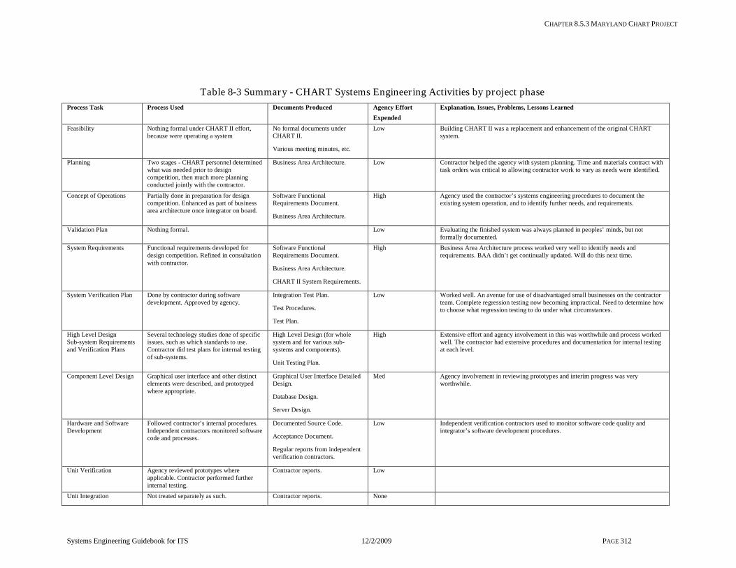
CHAPTER 8.5.3 MARYLAND CHART PROJECT
Systems Engineering Guidebook for ITS 12/2/2009 PAGE 312
Table 8-3 Summary - CHART Systems Engineer ing Activities by project phase Process Task Process Used Documents Produced Agency Effort
Expended Explanation, Issues, Problems, Lessons Learned
Feasibility Nothing formal under CHART II effort, because were operating a system
No formal documents under CHART II.
Various meeting minutes, etc.
Low Building CHART II was a replacement and enhancement of the original CHART system.
Planning Two stages - CHART personnel determined what was needed prior to design competition, then much more planning conducted jointly with the contractor.
Business Area Architecture. Low Contractor helped the agency with system planning. Time and materials contract with task orders was critical to allowing contractor work to vary as needs were identified.
Concept of Operations Partially done in preparation for design competition. Enhanced as part of business area architecture once integrator on board.
Software Functional Requirements Document.
Business Area Architecture.
High Agency used the contractor’s systems engineering procedures to document the existing system operation, and to identify further needs, and requirements.
Validation Plan Nothing formal. Low Evaluating the finished system was always planned in peoples’ minds, but not formally documented.
System Requirements Functional requirements developed for design competition. Refined in consultation with contractor.
Software Functional Requirements Document.
Business Area Architecture.
CHART II System Requirements.
High Business Area Architecture process worked very well to identify needs and requirements. BAA didn’t get continually updated. Will do this next time.
System Verification Plan Done by contractor during software development. Approved by agency.
Integration Test Plan.
Test Procedures.
Test Plan.
Low Worked well. An avenue for use of disadvantaged small businesses on the contractor team. Complete regression testing now becoming impractical. Need to determine how to choose what regression testing to do under what circumstances.
High Level Design Sub-system Requirements and Verification Plans
Several technology studies done of specific issues, such as which standards to use. Contractor did test plans for internal testing of sub-systems.
High Level Design (for whole system and for various sub-systems and components).
Unit Testing Plan.
High Extensive effort and agency involvement in this was worthwhile and process worked well. The contractor had extensive procedures and documentation for internal testing at each level.
Component Level Design Graphical user interface and other distinct elements were described, and prototyped where appropriate.
Graphical User Interface Detailed Design.
Database Design.
Server Design.
Med Agency involvement in reviewing prototypes and interim progress was very worthwhile.
Hardware and Software Development
Followed contractor’s internal procedures. Independent contractors monitored software code and processes.
Documented Source Code.
Acceptance Document.
Regular reports from independent verification contractors.
Low Independent verification contractors used to monitor software code quality and integrator’s software development procedures.
Unit Verification Agency reviewed prototypes where applicable. Contractor performed further internal testing.
Contractor reports. Low
Unit Integration Not treated separately as such. Contractor reports. None

CHAPTER 8.5.3 MARYLAND CHART PROJECT
Systems Engineering Guidebook for ITS 12/2/2009 PAGE 313
Process Task Process Used Documents Produced Agency Effort Expended
Explanation, Issues, Problems, Lessons Learned
Sub-system Verification Used test environment in contractor’s facilities. Contractor demonstrated user interface and other key items as soon as available.
Contractor reports. Low The test environment set up in the contractor’s facilities was valuable in conducting realistic component and sub-system testing. Independent verification contractor monitored this and other contractor internal processes.
Sub-system Integration Contractor performed integration. Contractor reports. None
System Verification Formal acceptance tests of the installed system were witnessed and approved by CHART personnel.
System Test Report.
Med Worked well. Found impractical to fix all problems. Write a problem report, evaluate cost of fixing it versus cost of operating with a workaround. Often best to leave it and pick it up in next build rather than delay deployment of the system.
Deployment Contractor took lead in deployment planning, for each build.
Transition Plan.
Operational Readiness Review.
High
Validation Informal feedback from the users. University of Maryland does periodic evaluation.
CHART Evaluation Reports.
E-mails from operators.
Low Evaluation by University of Maryland has confirmed that the system works as planned and delivers value for the investment. Informal operator feedback turned into requirements for future builds.
Operations and Maintenance
Contractor prepared operation (user), administration, and maintenance documentation for each build.
Operations and Maintenance Guide.
Users Guide.
Software Development Guide.
Med The Software Development Guide provides the information a third party developer would need to modify or interface with the existing CHART software. This is key to providing flexibility in choice of contractors for future work. Two separate contractors have already made system enhancements.
Changes and Upgrades Change control board. Configuration of hardware and software are tracked via three levels – requirements maintained in DOORS, problem reports in ClearQuest, and source code in ClearCase. Hardware configuration documented in mainframe financial reporting system.
Reports generated from online tools as needed.
Med Software configuration is managed very thoroughly. Hardware and network configuration are not so well managed, and an effort is underway to correct this.