system level s t -f c networksairccse.org/journal/jwmn/6614ijwmn01.pdf · lte is an emerging...
TRANSCRIPT

International Journal of Wireless & Mobile Networks (IJWMN) Vol. 6, No. 6, December 2014
DOI : 10.5121/ijwmn.2014.6601 1
SYSTEM LEVEL SIMULATION FOR TWO TIER
MACRO-FEMTO CELLULAR NETWORKS
1Shiqi Xing,
2Pantha Ghosal,
3Shouman Barua,
4 Ramprasad Subramanian and
5Kumbesan Sandrasegaran
Centre for Real-time Information Networks
School of Computing and Communications, Faculty of Engineering and Information
Technology, University of Technology Sydney, Sydney, Australia.
ABSTRACT
LTE is an emerging wireless communication technology to provide high- speed data service for the mobile
phones and data terminals. To improve indoor coverage and capacity Femtocells are included in 3GPP
since Release 8. There is no common simulation platform is available for performance justification of LTE-
Femtocells. LTE-Sim is an object-oriented open source simulator which incorporates a complete protocol
stack can be used for simulating two-tier macro-femto scenarios. To the best of our knowledge no paper
provides the guideline to perform system level simulation of Femtocell networks. Here, in this paper
Femtocells performance is evaluated in multi-Macrocells and multi-Femtocells environment with
interference from Microcells and Macrocell users along with the scripting.
KEYWORDS
Channel quality indicator (CQI), Femto Access Point (FAP), Macro eNodeB (MeNB), Macrocell User
Equepment (MUE), Moblity Management Entity(MME), Signal to Interference Plus Noise Ratio(SINR),
Physical Layer(PHY)
1.INTRODUCTION
Long Term Evaluation (LTE) is the next generation communication technology. LTE, which
supports high data transmission rate has upgraded the major network infrastructure by legacy
networks (GSM, GPRS, UMTS/HSPA) with the combination of circuit-switched and packet-
switched technology. With the higher frequency bands allocated to LTE, sometimes indoor
coverage becomes poor since penetration and path loss is higher for higher frequency bands.
Addressing the challenge of indoor coverage, and to provide high data transmission rate to users,
small, portable, short ranged (10-35m), low powered (10-100mW) Femto access [1] points were
integrated in 3GPP. The benefits of Femtocells include high coverage, high mobile data capacity,
improve battery life of mobile devices in the next generation wireless communication system.
Femtocells is operating at the frequency spectrum owned by the service operator and enable fixed
mobile convergence (FMC) [2] service by connecting to the core network via broadband
communication links such as Digital Subscriber Line (DSL). The portability and low cost makes
femtocells deployed by the owner in an unplanned manner; also the dense installation of
femtocells increases the complexity in mobility management and increases interference. For that

International Journal of Wireless & Mobile Networks (IJWMN) Vol. 6, No. 6, December 2014
2
purpose research on performance evaluation on accurate simulation framework is of utmost
importance. The current open-source simulation tools are only able to simulate parts of the LTE
system [3] but we are not aware of any simulator that allows femtocell architecture the media
access control (MAC) and physical layer (PHY) models with handover strategies and propagation
loss models for indoor environments. To bridge this gap, this paper describes our efforts to build
multi-cell and multi-user environment in femtocellular module in the existing open source LTE-
Sim framework [4] encompassing scenarios with both macro and femto cells
The rest of the paper is organized as, Section II. LTE Network Architecture with Femtocells.
Section III. Modelling and Coding in LTE-Sim. Section IV explains the simulation outcomes of
Femtocells module in LTE-Sim. Section V concludes the paper.
2.LTE FEMTOCELL: NETWORK ARCHITECTURE
2.1 LTE and Scheduling Frame
The LTE network architecture is divided into two parts: the air interfaces E-UTRAN, and the
packet switched core network (EPC) [5]. On the network side, the evolved NodeB (eNB) is the
only component of E-UTRAN, the main functionalities are 1) sending and receiving radio
transmission to all mobiles and data terminals in downlink and uplink respectively and 2)
controlling singling messages (such as Handover message) On the physical layer, LTE radio
interfaces supports both of Frequency Division Duplexing (FDD) and Time Division Duplexing
(TDD). Channel is based on Orthogonal Frequency Division Multiple Access (OFDMA). The use
of OFDMA removes the Inter Symbol Interferences since the transmitter uses a guard period
(cyclic prefix) longer than the channel response [6]. Radio resources are allocated in a
time/frequency domain. In the time domain, every Transmission Time Interval (TTI) has been
distributed into 1 ms. Each TTI is composed of two consecutive time slots of 0.5 ms and seven
OFDM symbols with short cyclic prefix. On the other side, in the frequency domain, the
bandwidth is divided into 180 kHz sub-channels, corresponding to 12 consecutive and equally
spaced sub-carriers.
2.2 Femtocell and Its challenges
Femtocell was introduced by 3GPP in Release 8 which has the functionalities of boosting the
indoor coverage and capacity. Femtocell may also improve battery life of mobile devices. Fig.1
shows the basic femtocell network architecture of macro-femto two-layer systems. According to
[3], femtocell access points are connected to the operator network through a DSL line at end user
like a common Wi-Fi access point.

International Journal of Wireless & Mobile Networks (IJWMN) Vol. 6, No. 6, December 2014
3
Fig.1. UEs inside building served by Femtocell
LTE system is operating on flat IP architecture which connects all the eNBs through X2
interfaces and Radio Resource Management (RRM) procedure is done by eNB. On the other hand,
there is no such X2 interface between eNB and FAP. As a result, Interference coordination [7],
RRM and HO management [8] are becoming complex with the unplanned and vast deployment of
LTE femtocells. Benefits of femtocells are coming with the increasing the complexity in
spectrum management. Femtocells are designed to operate in one of the three different access
modes, i.e., closed access mode, open access mode or hybrid access mode [9]. In closed access
mode, the UEs belong to the Closed Subscriber Group are allowed to get access to the femtocell.
However, the unauthorized users might affect by the interference from the femtocells in closed
access mode. In the case of open access mode, any UE could get access to the femtocells and
benefit from its services. On the other hand, depending on resource usage, congestion and
security consideration, open access is not a suitable choice. For hybrid access mode, a limited
number of unknown Macro UEs are allowed to access the femtocell by owners, but the owners
will suffer the risk of a security breach [10].
2.3 Femtocell Hand Over Modeling
According to [5], Fig. 2 illustrates three femtocell handover scenarios: Inbound Handover, i.e.,
the handover that takes place when user moves from the eNB to HeNB. Outbound scenario
denotes the handover from the HeNB to eNB. Inter FAP, i.e., UE handover from one femtocell to
other femtocells. Fig. 3 shows the Femtocell UE hand over to another femtocell.

International Journal of Wireless & Mobile Networks (IJWMN) Vol. 6, No. 6, December 2014
4
Fig.2: Handover modeling in presence of Femtocells [5]
Fig.3: Handover between Femtocells. [5]
2.4 Frequency reuse modeling
LTE supports Fractional Frequency Reuse. The main idea of FFR is to divide allocated spectrum
into several sub-bands and allocate these sub-bands in different macro cell coverage area or sub-
area [6]. Since, the resources are not overlapped in different sub-areas the cross-tier interference
between FAP and eNB can be mitigated. In [11] authors proposed “soft frequency reuse” scheme
where frequency spectrum is divided in centre and edge zones by adjusting transmitting power for
effective reuse.

International Journal of Wireless & Mobile Networks (IJWMN) Vol. 6, No. 6, December 2014
5
Fig.4: Frequency Planning and Power Allocation for SFR Scheme [11]
In Soft Frequency Reuse, the sub bands are orthogonal to each other and users at cell edge are
allocated a cell-edge band as illustrated in Fig. 4 with cluster of 7 cells. Users in the cell edge
band have higher power whereas Cell Centre Users of neighbouring cells also have access to the
selected cell edge bands but with lower power. Therefore, high spectral efficiency could be
achieved with user throughput. Though, intracell interference is reduced because of orthogonally
between bands but UEs experience higher ICI because the Orthogonality between cell edge band
of one cell and cell-interior bands of its neighbouring cells is not guaranteed. Strict FFR as shown
in Fig.4 is used mostly in multi cell networks and is actually a modification of traditional
Frequency reuse with a cell-edge reuse factor. In Fig.5, for the three cells illustrated, the cell
centre area is allocated the common sub-band while at the cell-edge remaining bandwidth is
portioned with a reuse factor 3. Here, cell centre users don’t share spectrum with exterior user and
reduce cross tier interference
International Journal of Wireless & Mobile Networks (IJWMN) Vol. 6, No. 6, December 2014
6
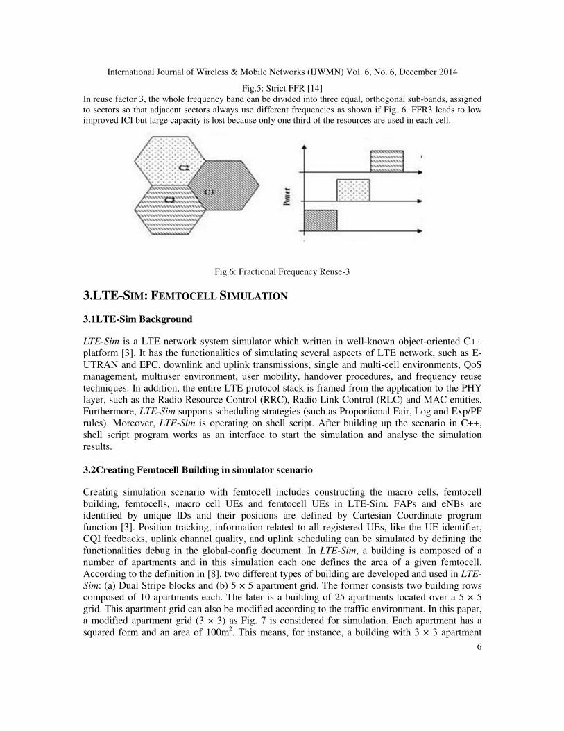
Fig.5: Strict FFR [14]
In reuse factor 3, the whole frequency band can be divided into three equal, orthogonal sub-bands, assigned
to sectors so that adjacent sectors always use different frequencies as shown if Fig. 6. FFR3 leads to low
improved ICI but large capacity is lost because only one third of the resources are used in each cell.
Fig.6: Fractional Frequency Reuse-3
3.LTE-SIM: FEMTOCELL SIMULATION
3.1LTE-Sim Background
LTE-Sim is a LTE network system simulator which written in well-known object-oriented C++
platform [3]. It has the functionalities of simulating several aspects of LTE network, such as E-
UTRAN and EPC, downlink and uplink transmissions, single and multi-cell environments, QoS
management, multiuser environment, user mobility, handover procedures, and frequency reuse
techniques. In addition, the entire LTE protocol stack is framed from the application to the PHY
layer, such as the Radio Resource Control (RRC), Radio Link Control (RLC) and MAC entities.
Furthermore, LTE-Sim supports scheduling strategies (such as Proportional Fair, Log and Exp/PF
rules). Moreover, LTE-Sim is operating on shell script. After building up the scenario in C++,
shell script program works as an interface to start the simulation and analyse the simulation
results.
3.2Creating Femtocell Building in simulator scenario
Creating simulation scenario with femtocell includes constructing the macro cells, femtocell
building, femtocells, macro cell UEs and femtocell UEs in LTE-Sim. FAPs and eNBs are
identified by unique IDs and their positions are defined by Cartesian Coordinate program
function [3]. Position tracking, information related to all registered UEs, like the UE identifier,
CQI feedbacks, uplink channel quality, and uplink scheduling can be simulated by defining the
functionalities debug in the global-config document. In LTE-Sim, a building is composed of a
number of apartments and in this simulation each one defines the area of a given femtocell.
According to the definition in [8], two different types of building are developed and used in LTE-
Sim: (a) Dual Stripe blocks and (b) 5 × 5 apartment grid. The former consists two building rows
composed of 10 apartments each. The later is a building of 25 apartments located over a 5 × 5
grid. This apartment grid can also be modified according to the traffic environment. In this paper,
a modified apartment grid (3 × 3) as Fig. 7 is considered for simulation. Each apartment has a
squared form and an area of 100m2. This means, for instance, a building with 3 × 3 apartment
International Journal of Wireless & Mobile Networks (IJWMN) Vol. 6, No. 6, December 2014
7
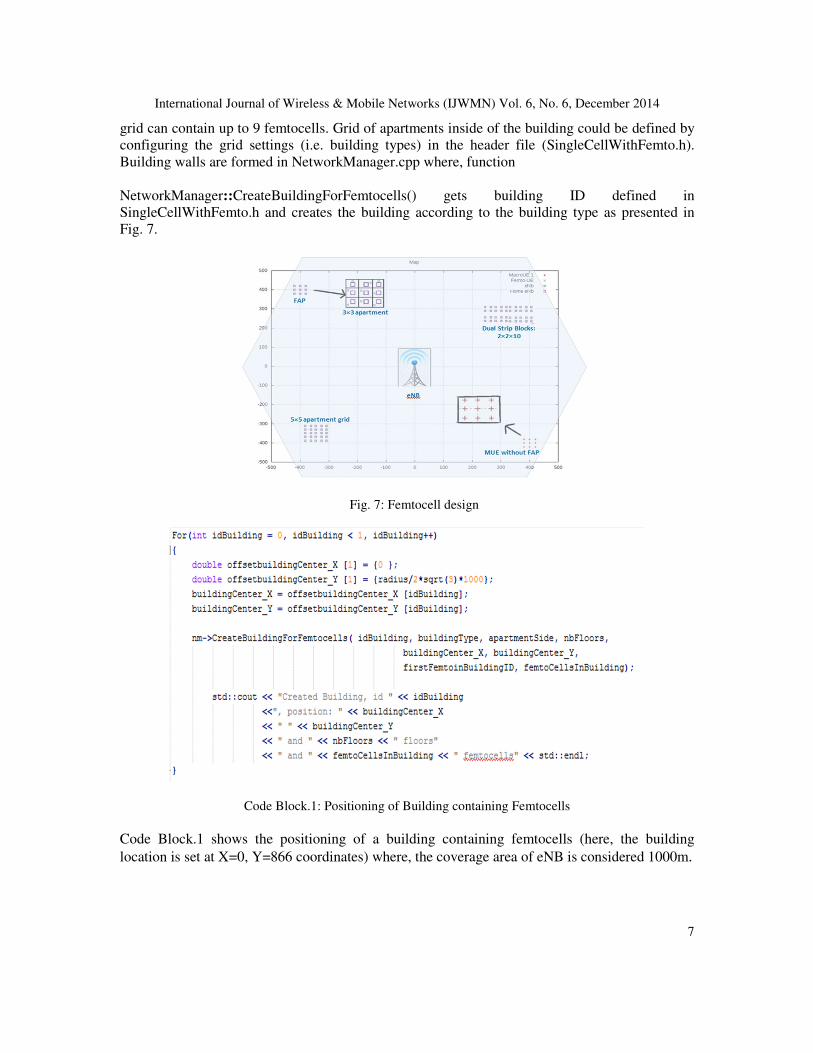
grid can contain up to 9 femtocells. Grid of apartments inside of the building could be defined by
configuring the grid settings (i.e. building types) in the header file (SingleCellWithFemto.h).
Building walls are formed in NetworkManager.cpp where, function
NetworkManager::CreateBuildingForFemtocells() gets building ID defined in
SingleCellWithFemto.h and creates the building according to the building type as presented in
Fig. 7.
Fig. 7: Femtocell design
Code Block.1: Positioning of Building containing Femtocells
Code Block.1 shows the positioning of a building containing femtocells (here, the building
location is set at X=0, Y=866 coordinates) where, the coverage area of eNB is considered 1000m.

International Journal of Wireless & Mobile Networks (IJWMN) Vol. 6, No. 6, December 2014
8
3.3Create UE in simulator
Code Block.2: Mobility of UE in different HO scenarios
In Code Block 2, it is shown how to create an user at coordinte (0,0) with mobility to perform
different HO in different scenarios. In our simulation we considered Random Direction[12] as our
mobility model. Here, the UE is moving North, as shown in Fig.8 will pass through femtocell
building and handover form Macrocell 1 -> Femtocell 1 -> Femtocell 2 -> Femtocell No.3 ->
Macrocell 2.
Fig.8: Mobility Pattern of the UE

International Journal of Wireless & Mobile Networks (IJWMN) Vol. 6, No. 6, December 2014
9
4.SIMULATION RESULT
In this section, some simulation outcomes regarding the change in SINR of UE in different
coverage area with and without presence of Femtocells are shown. The simulation results show:
(i)SINR improvement of the UE as it moves from macro-cellular coverage to femto-cellular
coverage area when FFR was not implemented, (ii) the SINR of the user further improves when
FFR was implemented (iii) a scalability test on computational requirements (i.e., simulation time
and CPU usage) was also performed at the end. Major simulation parameters are summarized in
Tab. 1. In our simulation, presences of two eNBs were considered along with the UE having the
access permission to all the femtocells. Building containing the femtocells in a 3 × 3 pattern is
located at the cell edge of two cells.
Table 1: Simulation Parameters
Total Bandwidth 5 MHz
eNb power transmission 43 dBm
FAP power transmission 20 dBm
CQI Full Bandwidth and periodic (2ms) reporting scheme
Apartment Size 100 m2
Mobility Model Random Direction
HO Type Position Based HO
Femto cell/Apartment 1/1
Frequency Reuse Soft FFR, Strict FFR, FFR3
Apartment orientation 3 × 3
Buildings 1
Users 1
Scheduler PF
Traffic VOIP, VIDEO
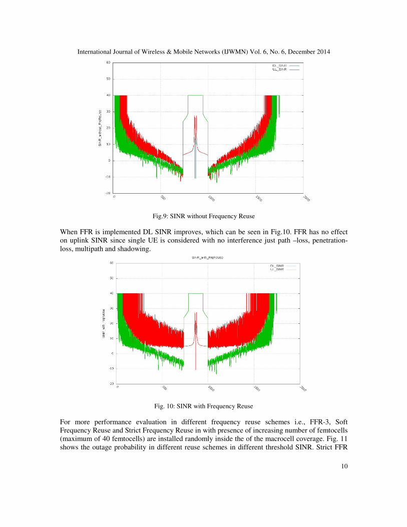
As we can see from the simulation result, illustrated in Fig. 9 that, when the UE is moving from
its initial position of Macrocell 1 coverage area to cell edge both the uplink and downlink SINR is
decreasing because of path-loss, penetration and macro-macro co-channel interference. Position
based HO model is considered in this simulation. As the UE moves closer to the FAP, HO takes
place from eNB to FAP and it can be seen from Fig. 9 that the SINR has rapid improvement
inside the FAP coverage area. Since we considered 3 × 3 apartment grid, it is also seen from the
figure that, UE passed three FAP coverage area and 3 successful HO attempts were made. The
fluctuation (three peaks in SINR graph inside FAP area) in SINR seen if Fig. 9 is because of the
handovers to three different femtocells. As the UE passed the FAP coverage area, SINR has
upward trend since, UE is moving towards the cell centre area of the Macrocell 2 coverage area.
International Journal of Wireless & Mobile Networks (IJWMN) Vol. 6, No. 6, December 2014
10
Fig.9: SINR without Frequency Reuse
When FFR is implemented DL SINR improves, which can be seen in Fig.10. FFR has no effect
on uplink SINR since single UE is considered with no interference just path –loss, penetration-
loss, multipath and shadowing.
Fig. 10: SINR with Frequency Reuse
For more performance evaluation in different frequency reuse schemes i.e., FFR-3, Soft
Frequency Reuse and Strict Frequency Reuse in with presence of increasing number of femtocells
(maximum of 40 femtocells) are installed randomly inside the of the macrocell coverage. Fig. 11
shows the outage probability in different reuse schemes in different threshold SINR. Strict FFR

International Journal of Wireless & Mobile Networks (IJWMN) Vol. 6, No. 6, December 2014
11
has better performance than the other two this is because in Strict FFR the cells centre FUEs are
not interfered by the FUEs of the edge area.
Fig. 11: Outage Probability Vs SINR Threshold in presence of Femtocells
The change in network throughput with the increase in number of femto cells is shown in Fig.12.
With the increase in femtocell number throughout the macrocell coverage the network throughput
decreases because of co-tier and cross tier interferences. FFR-3 schemes show the better network
throughput.
Fig. 12: Variation of Network Throughput with femtocell numbers
Fig.13 shows the spectrum efficiency of different reuse schemes in both cell centre(along with
edge) and edge. FFR-3 has the better spectral efficieny in both the case.

International Journal of Wireless & Mobile Networks (IJWMN) Vol. 6, No. 6, December 2014
12
Fig. 13: Spectral Efficiency of different frequency Reuse schemes
The scalability test of the presented simulation model was running on Linux machine with a 3.2
GHz (Dual Core) CPU and 8Gbytes of RAM. Obtained measurements in Fig. 14 shows the
simulation time and memory usage linearly increases with the increasing number of users and it
can be seen in Fig. 14c that the CPU usage (1 out of 4 cores was fully used) remains the same in
the scenarios with the highest computational load, which proofs the scalability of the presented
model in LTE-Sim.

International Journal of Wireless & Mobile Networks (IJWMN) Vol. 6, No. 6, December 2014
13
5.CONCLUSION In this article, demonstration to simulate femtocell scenarios with features and models compliant
with 3GPP specifications in LTE-Sim framework is provided. The femtocell scenario shown in
this paper can be used for investigating performances in a wider range that can differ in terms of
network layouts (i.e., number and position of base stations, building, and streets), system load
(i.e., number of users and applications) and so on. As a future study, we plan to enhance the LTE-
Sim Femtocell framework with the aim of implementing mobility management, Handover, Radio
Resource Allocation schemes [13] with random users both in eNB and FAP, handover, radio
resource allocation schemes [21] as well as other algorithms and protocols based on both self-
organizing network (SON) and cognitive paradigm believing the extreme modularity of LTE-Sim.
REFERENCES [1] L. Nuaymi, WiMAX: Technology for Broadband Wireless Access. Wiley, NewYork, 2008.
[2] E Dahlman, S Parkvall, J Skold, P Beming, 3G Evolution HSPA and LTE for Mobile Broadband.
Academia Press, USA, 2008.
[3] F. Capozzi, G. Piro, L. Grieco, G. Boggia, P. Camarda, "On Accurate simulations of LTE femtocells
using an open source simulator," in EURASIP Journal on Wireless Communication and
Networking, 2012.
[4] G Piro, L Grieco, G Boggia, F Capozzi, P Camarda,”Simulating LTE cellular systems: an open-
source framework, ” in Vehicular Technology, IEEE Trans. vol. 60, pp. 498-513, 2011.
[5] Raheem, Rand, Aboubaker Lasebae, and Jonathan Loo. "Performance Evaluation of LTE Network
via Using Fixed/Mobile Femtocells." Advanced Information Networking and Applications
Workshops (WAINA), 2014 28th International Conference on. IEEE, 2014.
[6] WCDMA for UMTS – HSPA Evolution and LTE, Fourth Edition. Edited by Harri Holma and
Antti Toskala © 2007 John Wiley & Sons, Ltd. ISBN: 978-0-470-31933-8
[7] D. Lopez-Perez, I. Guvenc, G. de la Roche, M. Kountouris, T. Q. S. Quek, and Z. Jie, "Enhanced
intercell interference coordination challenges in heterogeneous networks," IEEE Wireless Commun.,
vol. 18, pp. 22-30, 2011.
[8] D. Xenakis, N. Passas, L. Merakos, C. Verikoukis, “Mobility Management for Femtocells in LTE-
Advanced: Key Aspects and Survey of Handover Decision Algorithms” in IEEE Trans. Wireless
Commun., vol. 18 pp. 2011.
[9] R. Bendlin, V. Chandrasekhar, C. Runhua, A. Ekpenyong, and E. Onggosanusi, "From homogeneous
to heterogeneous networks: A 3GPP Long Term Evolution rel. 8/9 case study," in 45th Annu.
Conf., Inform. Sci. and Syst. (CISS), Baltimore, MD, pp. 1-5, 2011.
[10] H. Mahmoud, I .Guvenc,” A comparative study of different deployment modes for femtocell
networks,” in IEEE Int. Symposium on Personal, Indoor and Mobile Radio Commun. , Palo Alto,
USA, pp. 1–5, 2009.
[11] Siemens, R1-060135, “Interference Mitigation by Partial Frequency Reuse,” 3GPP RAN WG1#42,
London, UK, January 2006.
[12] T. Camp, J. Boleng, and V. Davies, “A survey of mobility models for ad hoc network research,”
Wireless Communications and Mobile Computing, vol. 2, pp. 483–502, Aug. 2002.
[13] F. Capozzi, G. Piro, L. Grieco, G. Boggia, P. Camarda, " A system-level simulation framework for
LTE Femtocell," in Proc. of International Conference on Simulation Tools and Techniques(ICST),
Desenzano, Italy, pp.1-3, 2012.
[14] http://www.infoutils.com/frequency-reuse-in-ofdma-based-ltewimax-system/
International Journal of Wireless & Mobile Networks (IJWMN) Vol. 6, No. 6, December 2014
14
Authors
Shiqi Xing is currently doing his Bachelor of Telecommunication Engineering at University of Technology,
Sydney. He is an experienced programmer and currently undertaking projects in 4G Telecommunication
and Robotics. Throughout his academic career he received several scholarships from The People’s
Republic of China.
Pantha Ghosal is a Graduate Research Assistant at Faculty of Engineering and Technology (FEIT), CRIN,
University of Technology, Sydney. Prior to this, he completed B.Sc in Electrical and Electronic
Engineering from Rajshahi University of Engineering & Technology, Bangladesh in 2007. He is an expert
of Telecommunication network design and holds more than 7 years of working experience in 2G/3G and
LTE. Throughout his career he was involved in several projects of RF Planning, Designing and
Dimensioning.
Shouman Barua is a PhD research scholar at the University of Technology, Sydney. He received his BSc
in Electrical and Electronic Engineering from Chittagong University of Engineering and Technology,
Bangladesh and MSc in Information and Communication Engineering from Technische Universität
Darmstadt (Technical University of Darmstadt), Germany in 2006 and 2014 respectively. He holds also
more than five years extensive working experience in telecommunication sector in various roles including
network planning and operation.
Ramprasad Subramanian is an experienced telecom engineer in the field of 2G/3G and LTE/LTE-A. He
holds M.S (By research) in Information and Communication from Institute of Remote Sensing, Anna
University (India)(2007) and Bachelors of Engineering in Electronics and Communication engineering
from Bharathidasan University (2001)(India). He has done many projects in the area of 2G/3G and LTE.
He has done many consultative projects across Africs/Americas/Asia etc. He was the recipient of India's
best invention award for the year 2004 from Indian Institute of Management Ahmadabad and Government
of India. His current research focuses on 4G mobile networks and vehicular Ad hoc networks.
Dr Kumbesan Sandrasegaran is an Associate Professor at UTS and Centre for Real-Time Information
Networks (CRIN). He holds a PhD in Electrical Engineering from McGill University (Canada)(1994), a
Master of Science Degree in Telecommunication Engineering from Essex University (1988) and a Bachelor
of Science (Honours) Degree in Electrical Engineering (First Class) (1985). His current research work
focuses on two main areas (a) radio resource management in mobile networks, (b) engineering of remote
monitoring systems for novel applications with industry through the use of embedded systems, sensors and
communications systems. He has published over 100 refereed publications and 20 consultancy reports
spanning telecommunication and computing systems.