system overview - lighting.philips.com · 2. lift light engine and slide back into place. tuck...
TRANSCRIPT
ATTENTION: Install in accordance with national and local building and electrical codes. ! Page 1
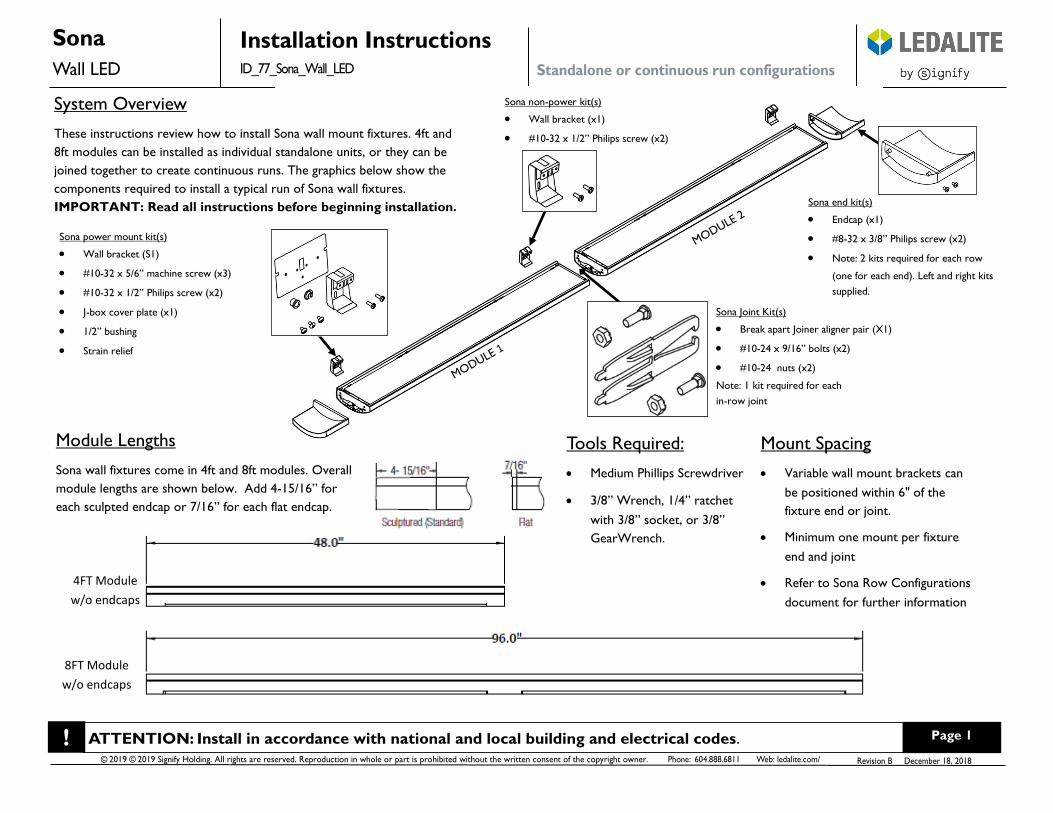
Tools Required:
• Medium Phillips Screwdriver
• 3/8” Wrench, 1/4” ratchet
with 3/8” socket, or 3/8”
GearWrench.
Mount Spacing
• Variable wall mount brackets can
be positioned within 6" of the
fixture end or joint.
• Minimum one mount per fixture
end and joint
• Refer to Sona Row Configurations
document for further information
Sona power mount kit(s)
• Wall bracket (S1)
• #10-32 x 5/6” machine screw (x3)
• #10-32 x 1/2” Philips screw (x2)
• J-box cover plate (x1)
• 1/2” bushing
• Strain relief
System Overview
These instructions review how to install Sona wall mount fixtures. 4ft and
8ft modules can be installed as individual standalone units, or they can be
joined together to create continuous runs. The graphics below show the
components required to install a typical run of Sona wall fixtures.
IMPORTANT: Read all instructions before beginning installation.
Module Lengths
Sona wall fixtures come in 4ft and 8ft modules. Overall
module lengths are shown below. Add 4-15/16” for
each sculpted endcap or 7/16” for each flat endcap.
4FT Module
w/o endcaps
8FT Module
w/o endcaps
Sona Joint Kit(s)
• Break apart Joiner aligner pair (X1)
• #10-24 x 9/16” bolts (x2)
• #10-24 nuts (x2)
Note: 1 kit required for each
in-row joint
Sona end kit(s)
• Endcap (x1)
• #8-32 x 3/8” Philips screw (x2)
• Note: 2 kits required for each row
(one for each end). Left and right kits
supplied.
Sona non-power kit(s)
• Wall bracket (x1)
• #10-32 x 1/2” Philips screw (x2)
ATTENTION: Install in accordance with national and local building and electrical codes. ! Page 2
!
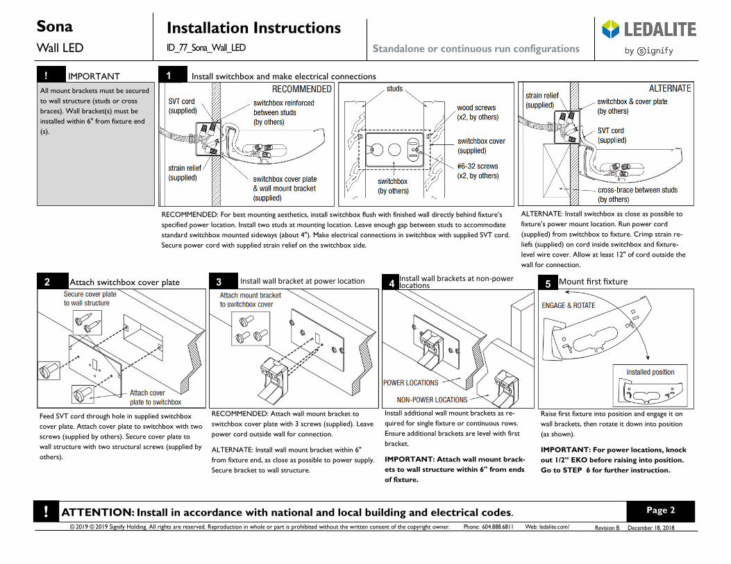
RECOMMENDED: For best mounting aesthetics, install switchbox flush with finished wall directly behind fixture’s
specified power location. Install two studs at mounting location. Leave enough gap between studs to accommodate
standard switchbox mounted sideways (about 4"). Make electrical connections in switchbox with supplied SVT cord.
Secure power cord with supplied strain relief on the switchbox side.
Feed SVT cord through hole in supplied switchbox
cover plate. Attach cover plate to switchbox with two
screws (supplied by others). Secure cover plate to
wall structure with two structural screws (supplied by
others).
1
2 3
ALTERNATE: Install switchbox as close as possible to
fixture’s power mount location. Run power cord
(supplied) from switchbox to fixture. Crimp strain re-
liefs (supplied) on cord inside switchbox and fixture-
level wire cover. Allow at least 12" of cord outside the
wall for connection.
5
IMPORTANT Install switchbox and make electrical connections
All mount brackets must be secured
to wall structure (studs or cross
braces). Wall bracket(s) must be
installed within 6" from fixture end
(s).
RECOMMENDED: Attach wall mount bracket to
switchbox cover plate with 3 screws (supplied). Leave
power cord outside wall for connection.
ALTERNATE: Install wall mount bracket within 6"
from fixture end, as close as possible to power supply.
Secure bracket to wall structure.
4
Install additional wall mount brackets as re-
quired for single fixture or continuous rows.
Ensure additional brackets are level with first
bracket.
IMPORTANT: Attach wall mount brack-
ets to wall structure within 6" from ends
of fixture.
Raise first fixture into position and engage it on
wall brackets, then rotate it down into position
(as shown).
IMPORTANT: For power locations, knock
out 1/2” EKO before raising into position.
Go to STEP 6 for further instruction.
Attach switchbox cover plate Install wall bracket at power location Install wall brackets at non-power locations Mount first fixture
ATTENTION: Install in accordance with national and local building and electrical codes. ! Page 3
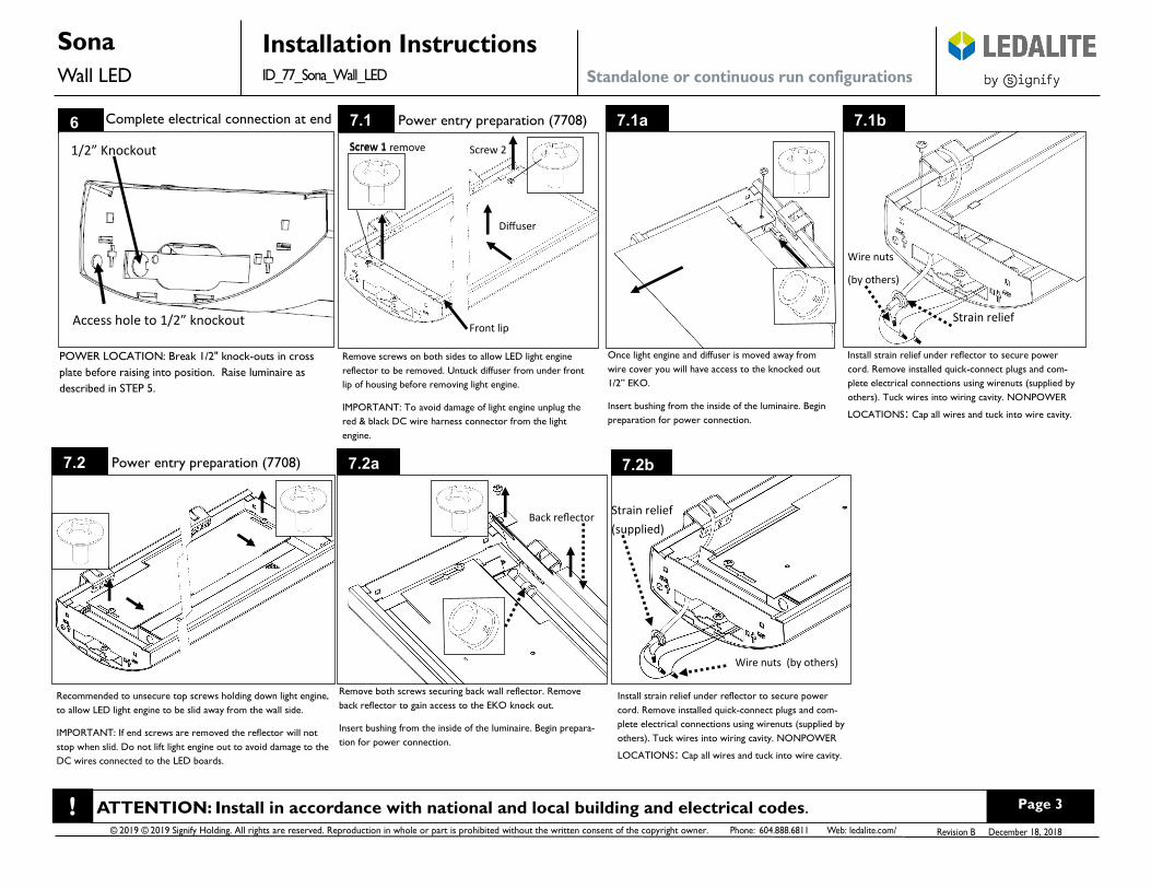
6 Complete electrical connection at end
Once light engine and diffuser is moved away from
wire cover you will have access to the knocked out
1/2” EKO.
Insert bushing from the inside of the luminaire. Begin
preparation for power connection.
Strain relief
Wire nuts
(by others)
1/2” Knockout
7.1
Access hole to 1/2” knockout
Remove screws on both sides to allow LED light engine
reflector to be removed. Untuck diffuser from under front
lip of housing before removing light engine.
IMPORTANT: To avoid damage of light engine unplug the
red & black DC wire harness connector from the light
engine.
Screw 1 remove Screw 2
Diffuser
Power entry preparation (7708)
POWER LOCATION: Break 1/2" knock-outs in cross
plate before raising into position. Raise luminaire as
described in STEP 5.
Front lip
Install strain relief under reflector to secure power
cord. Remove installed quick-connect plugs and com-
plete electrical connections using wirenuts (supplied by
others). Tuck wires into wiring cavity. NONPOWER
LOCATIONS: Cap all wires and tuck into wire cavity.
7.1a 7.1b
7.2 Power entry preparation (7708) 7.2a 7.2b
Screw 1
Recommended to unsecure top screws holding down light engine,
to allow LED light engine to be slid away from the wall side.
IMPORTANT: If end screws are removed the reflector will not
stop when slid. Do not lift light engine out to avoid damage to the
DC wires connected to the LED boards.
Remove both screws securing back wall reflector. Remove
back reflector to gain access to the EKO knock out.
Insert bushing from the inside of the luminaire. Begin prepara-
tion for power connection.
Back reflector
Strain relief
(supplied)
Wire nuts (by others)
Install strain relief under reflector to secure power
cord. Remove installed quick-connect plugs and com-
plete electrical connections using wirenuts (supplied by
others). Tuck wires into wiring cavity. NONPOWER
LOCATIONS: Cap all wires and tuck into wire cavity.
ATTENTION: Install in accordance with national and local building and electrical codes. ! Page 4
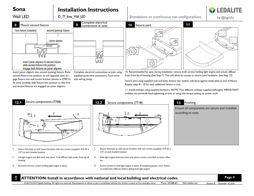
12.1 Secure components (7708)
1. Secure fixture(s) to wall mount brackets with two screws (supplied, #10-32 x
1/2") at each bracket location.
2. Lift light engine and slide back into place. Tuck diffuser back under front lip of
housing.
3. Re-insert the two screws holding light engine in place.
3 2 3
1
12.2 13 Secure components (7718) Finishing
Ensure all components are secure and installed
according to code.
1. Secure fixture(s) to wall mount brackets with two screws (supplied, #10-32 x
1/2") at each bracket location
2. Slide light engine back into place and secure screws once flush to back reflec-
tor.
3. Secure screws to hold light engine in place. If completing power entry fixture
re-install back reflector before sliding back light engine.
8 Mount second fixture
Insert joiner aligners into second (joining) fixture. Raise
second fixture into position; at end opposite joint, en-
gage fixture into wall mount bracket (shown in STEP 5).
At joint, carefully slide fixture into position so that first
and second fixtures are engaged on joiner aligners.
10. Recommended for ease during installation remove both screws holding light engine and untuck diffuser
from front lip of housing (See Step 7). This will allow for access to secure joint hardware. (see Step 12).
Secure joint using supplied nuts and bolts. Ensure star washer side faces against metal plate at end of fixture.
Repeat steps 8 - 10 for each additional fixture in row.
11. Install endcaps using supplied hardware. NOTE: Two different endcaps supplied (left/right). IMPORTANT:
Ledalite recommends hand-tightening screws or using low torque setting on power tools.
9 Complete electrical connections at joint
Complete electrical connections at joint using
supplied quick-wire connectors. Tuck wires
into wiring cavity.
10 Secure joint 11
1
2
3
3