system part numbers 200-378-xx 200-379-xx owner's manual · pdf filesystem part numbers...
TRANSCRIPT

Hydraulic Cargo Hook Kit with Load Weigh
For The
MD Helicopters 369 Series and 500N
System Part Numbers 200-378-XX 200-379-XX
Owner's Manual
Owner's Manual Number 120-207-00
Revision 5
August 14, 2017
13915 NW 3rd Court Vancouver Washington 98685 USA Phone: 360-546-3072 Fax: 360-546-3073 Toll Free: 800-275-0883
www.OnboardSystems.com

This page intentionally left blank.

ii
Record of Revisions
Revision
Date
Page(s)
Reason for Revision
0 03/02/11 All Initial Release
1 05/01/12 1-2, 1-3, 2-8 Added attach point assembly 232-449-01 (supersedes
232-449-00).
2 11/18/13 2-9 to 2-21 Updated pin load cell installation instructions.
3 08/21/15 1-2, 2-2, 2-9,
4-2, 4-3
Added load cell P/N 210-301-03. Updated cargo hook
rigging section.
4 02/04/16 All Added kit P/N’s 200-378-10, 200-379-01, 200-378-10,
and 200-379-11 which include cargo hook P/N 528-
028-02 with Surefire release.
5 08/14/17 2-15 Changed supplied bleed kit P/N to 212-014-02 which
includes MIL-PRF-87257 hydraulic fluid.
Current revision levels of all manuals are posted on Onboard Systems Int'l web site at
www.onboardsystems.com.
Register Your Products for Automatic Notifications
Onboard Systems offers a free notification service via fax or email for product alerts and
documentation updates. By registering your Onboard Systems products at our website, we will be
able to contact you if a service bulletin is issued, or if the documentation is updated.
You can choose to receive notices on an immediate, weekly, or monthly schedule via fax, email
or both methods. There is no charge for this service. Please visit our website at
www.onboardsystems.com/notify.php to get started.

This page intentionally left blank.

iii
CONTENTS Section 1 General Information
Introduction, 1-1
Safety Labels, 1-2
Bill of Materials, 1-3
Specifications, 1-4
Theory of Operation, 1-5
Section 2 Installation Instructions 2.1 Cargo Hook Removal, 2-1
2.2 Load Weigh System Installation, 2-2
2.3 Release Lever Assembly Installation, 2-6
2.4 Attach Point Installation, 2-8
2.5 Cargo Hook and Load Cell Installation, 2-9
2.6 Hydraulic System Bleed Procedure, 2-15
2.7 Installation Check-out, 2-20
2.8 Component Weights, 2-21
2.9 Cargo Hook Location, 2-21
Section 3 Operation Instructions Operating Procedures, 3-1
Cargo Hook Loading, 3-3
Cargo Hook Rigging, 3-3
Section 4 Maintenance Instructions for Returning a System to the Factory, 4-1
Section 5 Certification STC, 5-1
Canadian Approval, 5-3
ANAC STC, 5-4
ANAC AML, 5-6

This page intentionally left blank.
General Information 1-1
Section 1
General Information Introduction
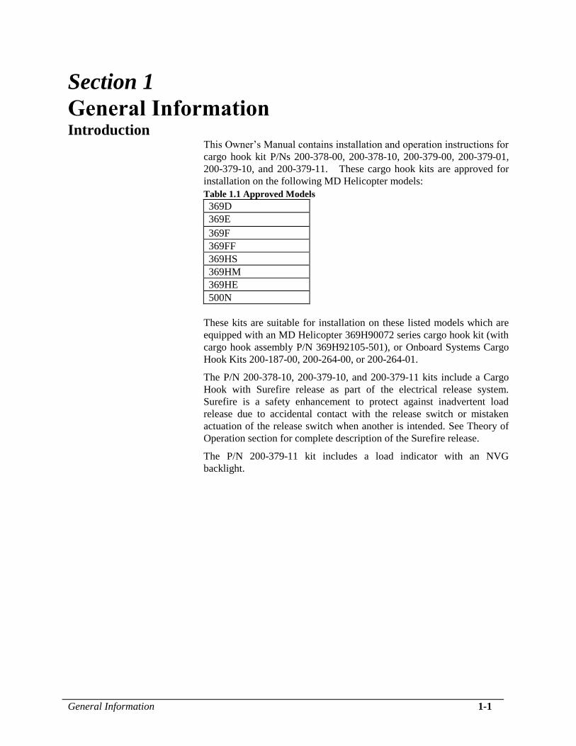
This Owner’s Manual contains installation and operation instructions for
cargo hook kit P/Ns 200-378-00, 200-378-10, 200-379-00, 200-379-01,
200-379-10, and 200-379-11. These cargo hook kits are approved for
installation on the following MD Helicopter models:
Table 1.1 Approved Models
369D
369E
369F
369FF
369HS
369HM
369HE
500N
These kits are suitable for installation on these listed models which are
equipped with an MD Helicopter 369H90072 series cargo hook kit (with
cargo hook assembly P/N 369H92105-501), or Onboard Systems Cargo
Hook Kits 200-187-00, 200-264-00, or 200-264-01.
The P/N 200-378-10, 200-379-10, and 200-379-11 kits include a Cargo
Hook with Surefire release as part of the electrical release system.
Surefire is a safety enhancement to protect against inadvertent load
release due to accidental contact with the release switch or mistaken
actuation of the release switch when another is intended. See Theory of
Operation section for complete description of the Surefire release.
The P/N 200-379-11 kit includes a load indicator with an NVG
backlight.
1-2 General Information
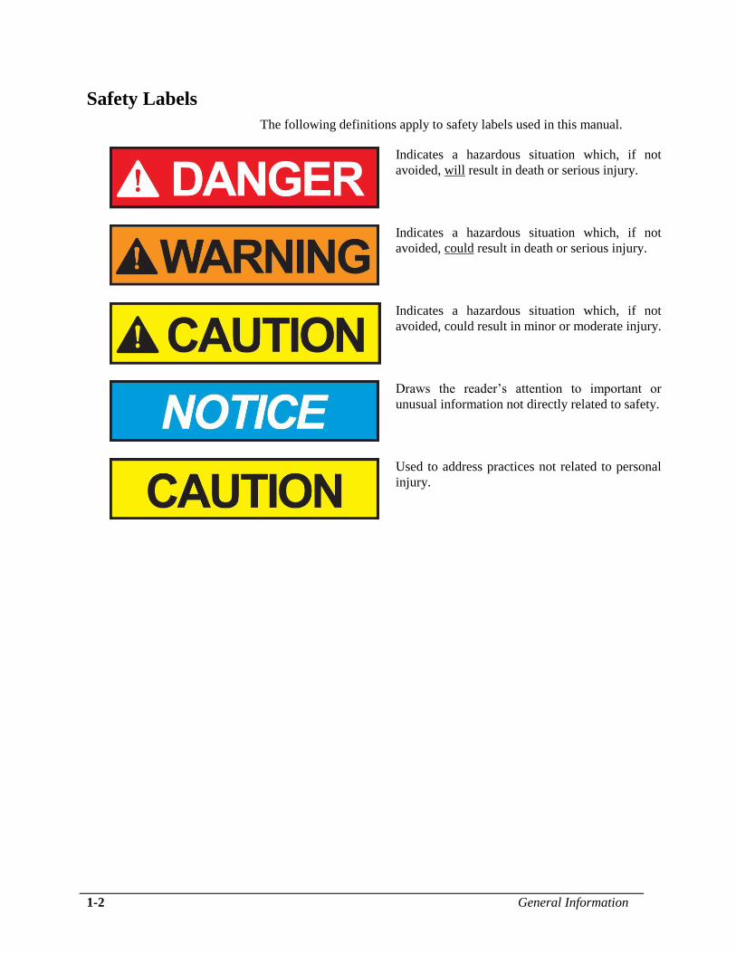
Safety Labels
The following definitions apply to safety labels used in this manual.
Indicates a hazardous situation which, if not
avoided, will result in death or serious injury.
Indicates a hazardous situation which, if not
avoided, could result in death or serious injury.
Indicates a hazardous situation which, if not
avoided, could result in minor or moderate injury.
Draws the reader’s attention to important or
unusual information not directly related to safety.
Used to address practices not related to personal
injury.

General Information 1-3
Bill of Materials The following items are included with the 200-378-XX and 200-379-XX
kits, if shortages are found contact the company from whom the system
was purchased. Table 1.2 Bill of Materials
Part No. Description Qty
200-378-XX
Qty
200-379-XX
-00 -10 -00 -01 -10 -11
210-095-00 C-39 Indicator Assembly - - 1 - 1 -
210-095-04 C-39 Indicator Assembly, NVG, 28V - - - 1 - 1
210-301-03** Pin Load Cell Assembly - - 1 1 1 1
212-014-02 Hydraulic Hook Bleed Kit 1 1 1 1 1 1
215-343-00 Cockpit Decal - Surefire - 1 - - 1 1
232-197-00 Release Lever Assy with Plumbing 1 1 1 1 1 1
232-203-00 Cargo Hook/Slave Cylinder Assembly 1 - 1 1 - -
232-203-02 Cargo Hook/Slave Cylinder Assembly - 1 - - 1 1
232-449-01* Attach Point Assembly 1 1 1 1 1 1
232-456-00 Spacer Assembly 1 1 1 1 1 1
270-047-01 Load Weigh Internal Harness - - 1 1 1 1
270-132-00 Electrical Release Harness 1 1 1 1 1 1
290-332-00 Attach Bolt 1 1 - - - -
290-909-00 Modified Loop Clamp 1 1 1 1 1 1
215-010-00 Load Weigh Placard - - 2 2 2 2
215-012-00 Load Weigh Placard - - 1 1 1 1
400-048-00 Power Switch - - 1 1 1 1
505-014-00 Grommet 1 1 1 1 1 1
505-015-00 Grommet 1 1 1 1 1 1
510-028-00 Screw, #4-40 - - 4 4 4 4
510-029-00 Nut - - 4 4 4 4
510-062-00 Washer - - 4 4 4 4
510-100-00 Washer 4 4 4 4 4 4
510-170-00 Nut 1 1 1 1 1 1
510-174-00 Washer 1 1 1 1 1 1
510-178-00 Cotter Pin 1 1 1 1 1 1
510-183-00 Washer 2 2 1 1 1 1
510-308-00 Bolt 4 4 4 4 4 4
512-001-00 Ty-rap – 3.5” 10 10 10 10 10 10
512-026-00 Cushioned Loop Clamp 2 2 2 2 2 2
590-013-00 Spiral Hose Wrap 18” 18” 18” 18” 18” 18”
120-039-00 Owner’s Manual, C-39 Load Indicator - - 1 1 1 1
120-207-00 Owner’s Manual 1 1 1 1 1 1
121-028-01 RFM Supplement 1 1 1 1 1 1
122-015-00 CMM, Cargo Hook 1 1 1 1 1 1
* Supersedes 232-449-00. 232-449-01 provides compatibility with the Onboard Systems E-51 load cell
assembly, otherwise these assemblies are interchangeable (the E-51 is approved under a separate STC).
** Supersedes P/N 210-226-03, these P/Ns are interchangeable in this installation.
1-4 General Information
Bill of Materials continued Kit P/N 200-383-00 is a load weigh upgrade kit intended for operators
using the 200-378-XX kit and who would like to add a load weighing
system. It converts the P/N 200-378-XX kit to a P/N 200-379-XX kit.
The following items are included with this kit, if shortages are found
contact the company from whom the system was purchased. Table 1.3 Bill of Materials – Kit P/N 200-383-00
Part No. Description Qty
210-095-00 C-39 Indicator Assembly 1
210-301-03 Pin Load Cell Assembly 1
270-047-01 Load Weigh Internal Harness 1
215-010-00 Load Weigh Placard 2
215-012-00 Load Weigh Placard 1
400-048-00 Power Switch 1
510-028-00 Screw, #4-40 4
510-029-00 Nut 4
510-062-00 Washer 4
120-039-00 Owner’s Manual, C-39 Load Indicator 1
Specifications Table 1.3 P/N 528-028-00, -02 Cargo Hook Specifications
Design load 3,500 lbs. (1,580 kg.)
Design ultimate strength 13,125 lbs. (5,953 kg.)
Electrical release capacity 8,750 lbs. (3,970 kg.)
Mechanical release capacity 8,750 lbs. (3,970 kg.)
Force required for mechanical
release at 3,500 lb.
14 lbs max. @ Master Cylinder
Electrical requirements 22-32 VDC 6.9 – 10 amps
Minimum release load 0 pounds
Unit weight 3.0 pounds (1.35 kg.)
Mating electrical connector PC05A8-2S
Table 1.4 P/N 232-449-00/-01 Attach Point Assembly Specifications
Design Load 2,500 lbs (1134 kgs)
Design Ultimate Strength 9,375 lbs (4,252 kgs)
Loads given are an indication of the structural
capacity of the equipment only. All helicopter
external load limits as described in the RFM still
apply.
General Information 1-5
Theory of Operation The primary elements of the Cargo Hook are the load beam, the internal
mechanism, and a DC solenoid. The load beam supports the load and is
latched through the internal mechanism. The DC solenoid and an external
hydraulic release system provide the means for unlatching the load beam.
The load is attached to the load beam by passing the cargo sling ring into
the throat of the load beam and pushing the ring against the upper portion of
the load beam throat, which will initiate the hook to close. In the closed
position, a latch engages the load beam and latches it in this position.
To release the load, the latch is disengaged from the load beam. With the
latch disengaged, the weight of the load causes the load beam to swing to its
open position, and the cargo sling slides off the load beam. The load beam
then remains in the open position awaiting the next load.
A load release can be initiated by three different methods. Normal release is
achieved by pilot actuation of the push-button release switch in the cockpit.
When the switch is pressed, it energizes the DC solenoid in the Cargo
Hook, and the solenoid opens the latch in the internal mechanism. In an
emergency, release can be achieved by operating a hydraulic release lever.
The hydraulic release lever operates the internal mechanism of the Cargo
Hook to unlatch the load beam. The load can also be released by the
actuation of a lever located on the side of the Cargo Hook.
The optional cargo hook with Surefire includes a short time delay circuit
built into the cargo hook’s electrical release system (cargo hook P/N 528-
028-02). This feature is a safety enhancement to protect against inadvertent
load release due to accidental contact with the release switch or mistaken
actuation of the cargo hook switch when another is intended. The time delay
feature requires that the release switch be depressed and held for more than
a 1/2 second to open the cargo hook. Surefire makes the electrical release a
more deliberate pilot command. If the cargo hook must be released
immediately, use the mechanical backup release.
In addition to its P/N, a cargo hook with Surefire can be identified by a gold
color solenoid housing (see Figure 1.3). Also a placard on the underside of
the solenoid housing indicates that the electrical release is delayed by ½
second.

1-6 General Information
Theory of Operation continued
The 528-028-02 cargo hook includes an electronic
delay of approximately ½ second. It is necessary
to press and hold the cargo hook release button.
If a Surefire-equipped cargo hook must be
released immediately without any delay (such as
the case of engine failure or snagged load), use
the mechanical backup release.
In addition to the delay feature the circuit includes on-off cycling to limit
the duty-cycle on the cargo hook solenoid. If the release switch is held
down, the solenoid will cycle on and off repeatedly in a “machine gun”
fashion.
Figure 1.3 Surefire Configuration Identification
Gold color solenoid housing
indicates Cargo Hook with
Surefire release.
Placard indicates need
to hold release switch to
release load.
Installation Instructions 2-1
Section 2
Installation Instructions These procedures are provided for the benefit of experienced aircraft
maintenance facilities capable of carrying out the procedures. They must
not be attempted by those lacking the necessary expertise.
2.1 Existing Equipment Removal Remove the existing Cargo Hook from the aircraft and disconnect the
electrical release cable from the belly mounted bulkhead connector.
Disconnect the manual release cable from the cargo hook and remove
the entire cable and manual release lever from the aircraft by
disconnecting it from the cyclic stick and attaching clamps.
Remove the bolt used to attach the Cargo Hook and/or load cell to the
attach point or load cell (if installed) and separate the Cargo Hook from
the aircraft.
Remove existing attach point components by removing the four bolts
and washers that attach it to the belly of the helicopter.
2-2 Installation Instructions
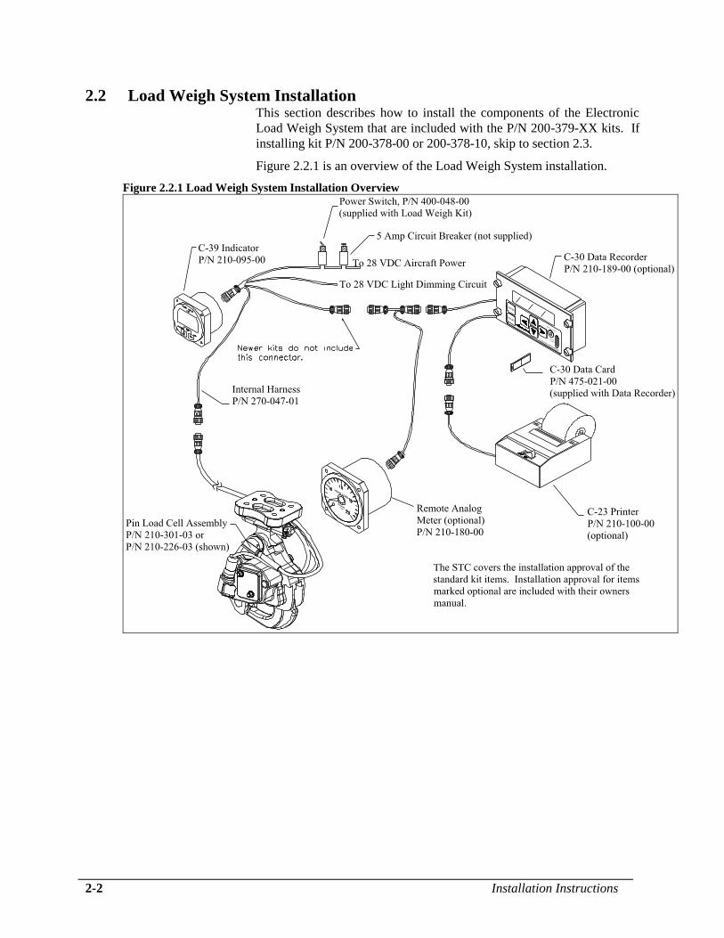
2.2 Load Weigh System Installation This section describes how to install the components of the Electronic
Load Weigh System that are included with the P/N 200-379-XX kits. If
installing kit P/N 200-378-00 or 200-378-10, skip to section 2.3.
Figure 2.2.1 is an overview of the Load Weigh System installation.
Figure 2.2.1 Load Weigh System Installation Overview

Installation Instructions 2-3
2.2 Load Weigh System Installation continued
2.2.1 Internal Harness Installation The Internal Harness (P/N 270-047-01) is made up of four cables
terminated to one connector. The connector is plugged into the back of
the Indicator. One of the cables is marked “LOAD CELL” and is fitted
with a bulkhead connector. This cable is connected to the connector
from the load cell. Another cable is marked “POWER” and is connected
to the aircraft electrical power. Another cable is marked “LIGHT” and
is used to power the indicator’s back lighting (refer to section 2.2.2 for
installation instructions). The last cable is marked “DATA” and can be
connected to the optional Data Recorder or Analog Slave Meter. These
optional items are not included under this STC.
The data cable may or may not be terminated with
a connector depending on manufacture date.
Locate a convenient position directly aft of the existing hole in the
aircraft skin that allowed the manual release cable to pass through (under
the pilot’s seat) to install the load cell bulkhead connector. Layout the
connector hole pattern and drill the required holes. Install the bulkhead
connector with the supplied hardware (screw P/N 510-028-00 (qty 4),
nut P/N 510-029-00 (qty 4), and washer P/N 510-062-00 (qty 4)).
Secure the cables to the existing wiring bundles with the Ty-wraps
provided. If it is necessary to remove the load cell bulkhead connector
to ease cable routing, connect using the color code below.
Table 2.2.1 Load Cell Bulkhead Connections
Wire Color Connector Pin
White A
WH/GN B
WH/OR C
WH/BLU D
Shield E
Ensure the cables are clear of flight control rods.
2-4 Installation Instructions
2.2 Load Weigh System Installation continued
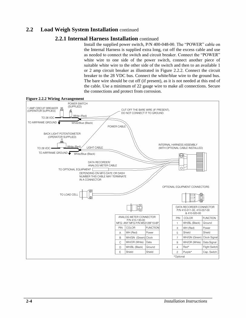
2.2.1 Internal Harness Installation continued Install the supplied power switch, P/N 400-048-00. The “POWER” cable on
the Internal Harness is supplied extra long, cut off the excess cable and use
as needed to connect the switch and circuit breaker. Connect the “POWER”
white wire to one side of the power switch, connect another piece of
suitable white wire to the other side of the switch and then to an available 1
or 2 amp circuit breaker as illustrated in Figure 2.2.2. Connect the circuit
breaker to the 28 VDC bus. Connect the white/blue wire to the ground bus.
The bare wire should be cut off (if present), as it is not needed at this end of
the cable. Use a minimum of 22 gauge wire to make all connections. Secure
the connections and protect from corrosion.
Figure 2.2.2 Wiring Arrangement
Ground1 WH/BL (Black)
Power
Shield5
3
Shield
WH (Red)
Data Signal
Clock Signal
Flight Switch
Cap. Switch
7
9
4
2 Purple*
WH/OR (White)
WH/GN (Green)
Red*
ShieldShieldE
Ground
Data
Clock
Power
WH/BL (Black)
WH/OR (White)
WH/GN (Green)
D
C
B
P/N 410-130-00
WH (Red)A
PIN COLOR FUNCTION
PIN COLOR FUNCTION
OPTIONAL EQUIPMENT CONNECTORS
*Optional
ANALOG METER CONNECTOR
P/N 410-011-00, 410-057-00
DATA RECORDER CONNECTOR
& 410-020-00
MFG: ANY MFG P/N:MS3126F10-6P
TO OPTIONAL EQUIPMENT
DATA RECORDER/
ANALOG METER CABLE
DEPENDING ON MFG DATE OR DASH
NUMBER THIS CABLE MAY TERMINATE
IN A CONNECTOR
TO LOAD CELL
TO AIRFRAME GROUND
TO 28 VDC
POWER SWITCH
(SUPPLIED)1 AMP CIRCUIT BREAKER
(OPERATOR SUPPLIED)
TO 28 VDC
TO AIRFRAME GROUND White/Blue (Black)
White (Red)
POWER CABLE
LIGHT CABLE
White/Blue (Black)
White (Red)
CUT OFF THE BARE WIRE (IF PRESENT),
DO NOT CONNECT IT TO GROUND.
BACK LIGHT POTENTIOMETER
(OPERATOR SUPPLIED)
INTERNAL HARNESS ASSEMBLY
(WITH OPTIONAL CABLE INSTALLED)

Installation Instructions 2-5
2.2 Load Weigh System Installation continued
2.2.1 Internal Harness Installation continued
If the C-23 Printer is being utilized with the C-30
Data Recorder, a 5 amp circuit breaker should be
used.
2.2.2 Indicator Installation The Indicator should be mounted in a position that is convenient, accessible
and visible to the pilot. It can be mounted in a standard 2¼" instrument
hole.
Connect the Internal Harness to the Indicator connector. Install the placard
P/N 215-010-00 “ELECTRONIC WEIGHING SYSTEM” next to the power
switch and circuit breaker. Install placard P/N 215-012-00 “TURN THE
WEIGHING SYSTEM OFF WHEN NAVIGATION EQUIPMENT IN
USE” “NO AIRCRAFT OPERATION SHOULD BE PREDICATED ON
THE READING OF THE ONBOARD WEIGHING SYSTEM” next to the
Indicator.
The 210-095-00 Indicator is equipped with an Internal Back Lighting
System that can be connected to the aircraft 28 VDC light dimming circuit.
Use a 22 gauge, twisted pair, shielded cable to connect the aircraft dimming
circuit to the Internal Harness. Connect the cable shield wire to airframe
ground at the light dimmer end of the cable ONLY.

2-6 Installation Instructions
2.3 Release Lever Assembly Installation The hydraulic release system is supplied dry. It is recommended that the
system be filled and bled on the bench before installing on the helicopter.
Refer to section 2.6 for filling and bleeding instructions.
o Remove the two screws (P/N 510-390-00) provided pre-assembled onto
the assembly.
o Position the Release Lever Assembly w/ Plumbing (P/N 232-197-00) on
the pilot’s cyclic stick as shown below and re-install the screws but do
not fully tighten at this point.
o Adjust the location if necessary so that the lever is accessible and
comfortably reached by hand from the cyclic stick grip but not be able
to contact or interfere with operation of any cyclic grip control when it
is fully actuated. This will be verified at installation check out (when
the release system is operational).
Figure 2.3.1 Release Lever Assembly Installation
CARGO HOOK
EMERGENCY
RELEASE
2.38/2.75
Hydraulic Hose
Release Lever Assembly
(P/N 232-198-00)
Screws (P/N 510-390-00)

Installation Instructions 2-7
2.3 Release Lever Assembly Installation continued o The hydraulic hose on the cyclic should follow the same path as the
manual release cable that is shown in MDHC Publication CSP-005.
o Secure the hydraulic hose to the cyclic using the same clamps that were
used with the manual release cable.
o The quick disconnect end of the hose is to be routed to underneath the
cabin floor using the same hole that the manual release cable used.
Open up the hole to 0.69 inches (17.5 mm) to accommodate the quick
disconnect and grommet P/N 505-014-00. If necessary, split the
grommet to facilitate installation.
o Connect the hose at the quick disconnect to the hose routed from the
slave cylinder at the Cargo Hook.
o Secure to prevent free movement or chafing during flight.
Figure 2.3.2 Master Cylinder Hose Routing
Hydraulic Hose
Hose from slave cylinder on Cargo Hook
(to be installed later).
FWD
STA 63
Clamps (MD Helicopters part)
cabin floor
Fuselage skin
Grommet
Release Lever Assembly
quick disconnect
coupling
2-8 Installation Instructions
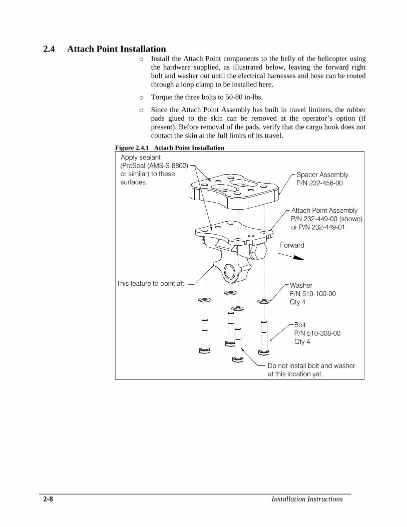
2.4 Attach Point Installation o Install the Attach Point components to the belly of the helicopter using
the hardware supplied, as illustrated below, leaving the forward right
bolt and washer out until the electrical harnesses and hose can be routed
through a loop clamp to be installed here.
o Torque the three bolts to 50-80 in-lbs.
o Since the Attach Point Assembly has built in travel limiters, the rubber
pads glued to the skin can be removed at the operator’s option (if
present). Before removal of the pads, verify that the cargo hook does not
contact the skin at the full limits of its travel.
Figure 2.4.1 Attach Point Installation
Attach Point Assembly
P/N 232-449-00 (shown)
or P/N 232-449-01.
Spacer Assembly
P/N 232-456-00
Washer
P/N 510-100-00
Qty 4
Bolt
P/N 510-308-00
Qty 4
This feature to point aft.
Do not install bolt and washer
at this location yet.
Apply sealant
(ProSeal (AMS-S-8802)
or similar) to these
surfaces.
Forward

Installation Instructions 2-9
2.5 Cargo Hook and Load Cell Installation o Connect the cargo hook to the Attach Point Assembly with Attach Bolt
(applicable to kit P/Ns 200-378-XX) or the Pin Load Cell Assembly (kit
P/Ns 200-379-XX) as shown below. The cargo hook load beam must
point forward.
Figure 2.5.1 Cargo Hook Installation w/o Pin Load Cell
Nut
P/N 510-170-00
Washer
P/N 510-183-00
Washer
P/N 510-174-00
Cotter Pin
P/N 510-178-00
Washer
P/N 510-183-00
Attach Bolt
P/N 290-332-00
Figure 2.5.2 Cargo Hook Installation w/ Pin Load Cell
Forward
Cotter Pin
P/N 510-178-00
Nut
P/N 510-170-00
Washer
P/N 510-183-00
Washer
P/N 510-174-00
Pin Load Cell Assembly
P/N 210-301-03 (shown)
or P/N 210-226-03

2-10 Installation Instructions
2.5 Cargo Hook and Load Cell Installation continued
o Tighten nut on cargo hook attach bolt or pin load cell until fully seated,
finger tight only. Back off nut to previous castellation, if needed, when
aligning cotter pin for installation. Install and secure cotter pin.
Do not tighten nut on pin load cell more than
finger tight. Over-tightening will damage load
cell.
Figure 2.5.3 Pin Load Cell Tightening
Installation Instructions 2-11
2.5 Cargo Hook and Load Cell Installation continued
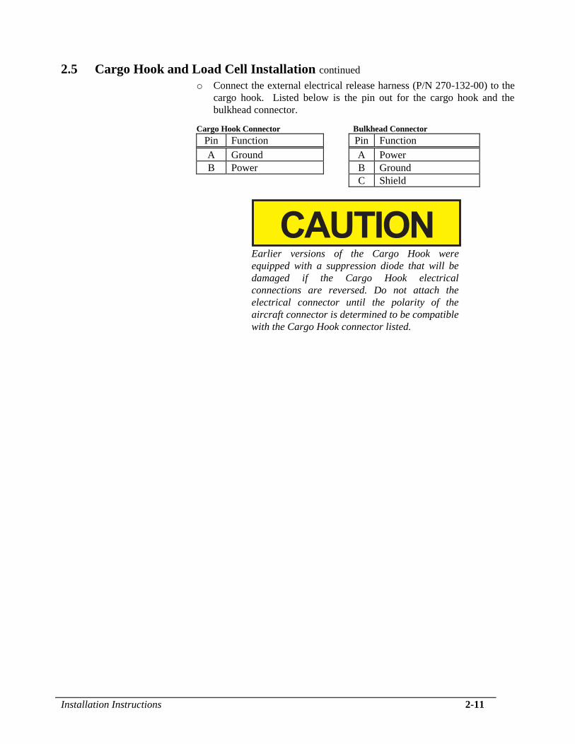
o Connect the external electrical release harness (P/N 270-132-00) to the
cargo hook. Listed below is the pin out for the cargo hook and the
bulkhead connector.
Cargo Hook Connector Bulkhead Connector
Pin Function Pin Function
A Ground A Power
B Power B Ground
C Shield
Earlier versions of the Cargo Hook were
equipped with a suppression diode that will be
damaged if the Cargo Hook electrical
connections are reversed. Do not attach the
electrical connector until the polarity of the
aircraft connector is determined to be compatible
with the Cargo Hook connector listed.

2-12 Installation Instructions
2.5 Cargo Hook and Load Cell Installation continued o Place the supplied loop clamp (P/N 290-909-00) over the electrical
release and load cell (if present) wire harnesses and the hydraulic hose
and loosely attach it at the forward right attach point mounting hole.
Do not fully tighten the bolt at this point.
o Route the harness and hose approximately as shown and install the
supplied spiral wrap (P/N 590-013-00) over them (see Figure 2.5.5).
Adjust loop as necessary to allow full swing of the cargo hook without
pulling or pinching the loop.
The routing must provide adequate slack in the
harness and hose so that any range or direction
of cargo hook travel does not create tension in
any of these. Swing the cargo hook in all
directions and ensure that the harness and hose
are not pulled tight or adversely kinked in any
position.
o After achieving a satisfactory loop for the hose and harnesses tighten
the bolt where the loop clamp is installed to 50-80 in-lbs. and ensure
that the hose and wire harnesses are not loose in the clamp.
o Safety wire the attach point bolts together in pairs.
Figure 2.5.5 Hose and Harness Routing at Cargo Hook
Forward
Load Cell Harness
Electrical Release Harness
Hydraulic Hose
Wrap bundle with spiral wrap
in this area.
Adjust loop size to allow full
movement of cargo hook without hose
and harnesses being pulled tight.
Installation Instructions 2-13
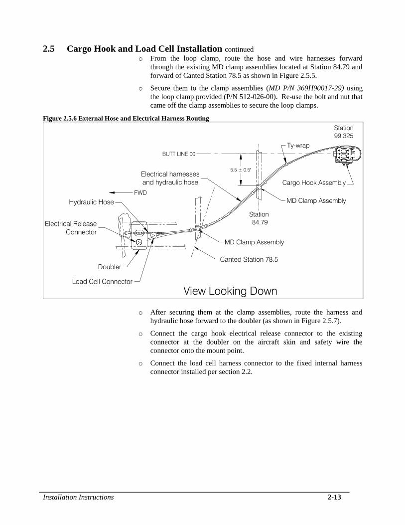
2.5 Cargo Hook and Load Cell Installation continued o From the loop clamp, route the hose and wire harnesses forward
through the existing MD clamp assemblies located at Station 84.79 and
forward of Canted Station 78.5 as shown in Figure 2.5.5.
o Secure them to the clamp assemblies (MD P/N 369H90017-29) using
the loop clamp provided (P/N 512-026-00). Re-use the bolt and nut that
came off the clamp assemblies to secure the loop clamps.
Figure 2.5.6 External Hose and Electrical Harness Routing
5.5 ± 0.5"
Station
84.79
Canted Station 78.5
FWD
View Looking Down
Doubler
Station
99.325
Electrical harnesses
and hydraulic hose.
Electrical Release
Connector
Load Cell Connector
Hydraulic Hose
MD Clamp Assembly
Cargo Hook Assembly
Ty-wrap
MD Clamp Assembly
BUTT LINE 00
o After securing them at the clamp assemblies, route the harness and
hydraulic hose forward to the doubler (as shown in Figure 2.5.7).
o Connect the cargo hook electrical release connector to the existing
connector at the doubler on the aircraft skin and safety wire the
connector onto the mount point.
o Connect the load cell harness connector to the fixed internal harness
connector installed per section 2.2.
2-14 Installation Instructions
2.5 Cargo Hook and Load Cell Installation continued
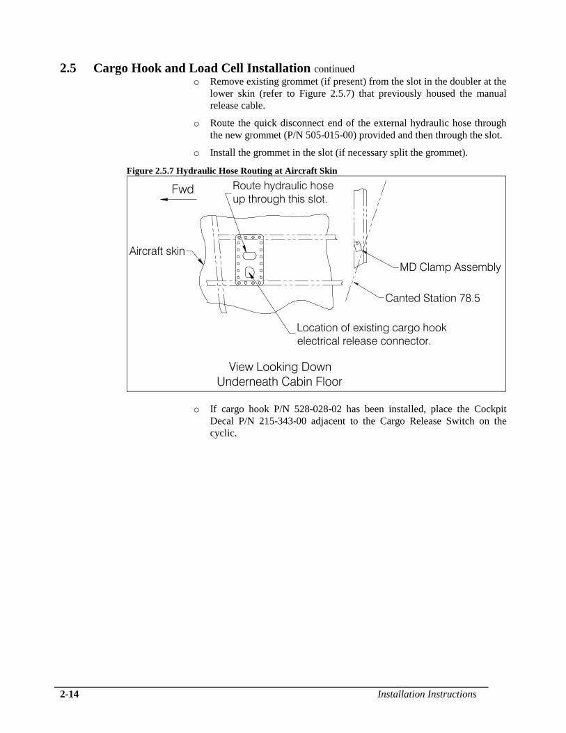
o Remove existing grommet (if present) from the slot in the doubler at the
lower skin (refer to Figure 2.5.7) that previously housed the manual
release cable.
o Route the quick disconnect end of the external hydraulic hose through
the new grommet (P/N 505-015-00) provided and then through the slot.
o Install the grommet in the slot (if necessary split the grommet).
Figure 2.5.7 Hydraulic Hose Routing at Aircraft Skin
Route hydraulic hose
up through this slot.
Canted Station 78.5
MD Clamp Assembly
Location of existing cargo hook
electrical release connector.
Fwd
Aircraft skin
View Looking Down
Underneath Cabin Floor
o If cargo hook P/N 528-028-02 has been installed, place the Cockpit
Decal P/N 215-343-00 adjacent to the Cargo Release Switch on the
cyclic.

Installation Instructions 2-15
2.6 Hydraulic System Bleed Procedure Each hydraulic system is typically shipped dry. A label affixed to the Master
Cylinder and Slave Cylinder assemblies will state if the assembly has been
filled and bled. Proper bleeding is critical to the operation of the hydraulic
release system. An improperly bled system will not release the cargo hook
mechanism.
A reservoir seal is installed beneath the reservoir lid. This seal serves to prevent
hydraulic fluid left over from the testing process from leaking during shipping.
The reservoir seal is for shipping purposes only
and must be removed and discarded before
bleeding of the hydraulic release system.
If there is a need to fill and/or bleed the system, follow the procedures listed
below. If there is a need to remove and repair any items in the hydraulic
system, refer to 123-021-01, Instruction for Continued Airworthiness.
Filling and bleeding the hydraulic release system is most easily accomplished
on the bench, prior to installation on the aircraft. This process may also be
accomplished after the system is installed. Filling and bleeding requires two
persons, one to inject hydraulic fluid through the system and the other to
observe the reservoir.
Bleeding procedure:
1. Assemble the supplied bleed kit 212-014-02 by press fitting each of the kit’s
components together as shown in Figure 2.6.1. This kit also includes 2
ounces of MIL-PRF-87257 fluid.
MIL-PRF-5606 fluid is also compatible with the
hydraulic system and was formerly included with
new cargo hook kits. It is interchangeable and
miscible with MIL-PRF-87257 fluid.
Figure 2.6.1 Hydraulic Hook Bleed Kit
PVC tubing
female X barb fitting syringe
bleed adapter

2-16 Installation Instructions
2.6 Hydraulic System Bleed Procedure continued
Use best shop practices to keep foreign material
out of the hydraulic system. FOD will plug
orifices, damage seals and/or scratch sealing
surfaces necessitating system rebuild. Use only
clean hydraulic fluid from sealed containers.
2. Connect the master cylinder assembly to the slave cylinder assembly if not
already done. If filling or bleeding on the bench, as much as possible,
arrange the hoses uncoiled, straight and running uphill. See Figure 2.6.2.
Figure 2.6.2 Hose Arrangement
Good Hose Arrangement
Poor Hose Arrangement
3. Remove screws, reservoir lid, and baffle from the master cylinder reservoir
as shown in Figure 2.6.3.
Figure 2.6.3 Reservoir Disassembly
Baffle
Screw (2)
Reservoir Lid
Installation Instructions 2-17
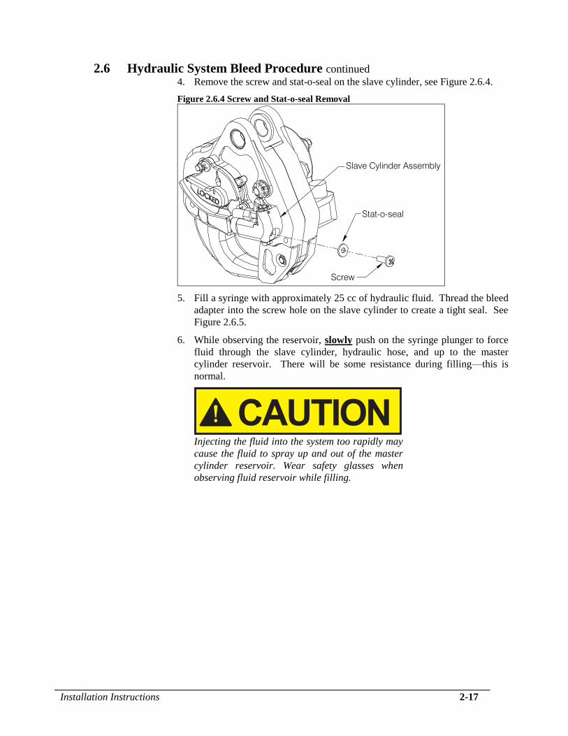
2.6 Hydraulic System Bleed Procedure continued 4. Remove the screw and stat-o-seal on the slave cylinder, see Figure 2.6.4.
Figure 2.6.4 Screw and Stat-o-seal Removal
Stat-o-seal
Screw
Slave Cylinder Assembly
5. Fill a syringe with approximately 25 cc of hydraulic fluid. Thread the bleed
adapter into the screw hole on the slave cylinder to create a tight seal. See
Figure 2.6.5.
6. While observing the reservoir, slowly push on the syringe plunger to force
fluid through the slave cylinder, hydraulic hose, and up to the master
cylinder reservoir. There will be some resistance during filling—this is
normal.
Injecting the fluid into the system too rapidly may
cause the fluid to spray up and out of the master
cylinder reservoir. Wear safety glasses when
observing fluid reservoir while filling.
2-18 Installation Instructions
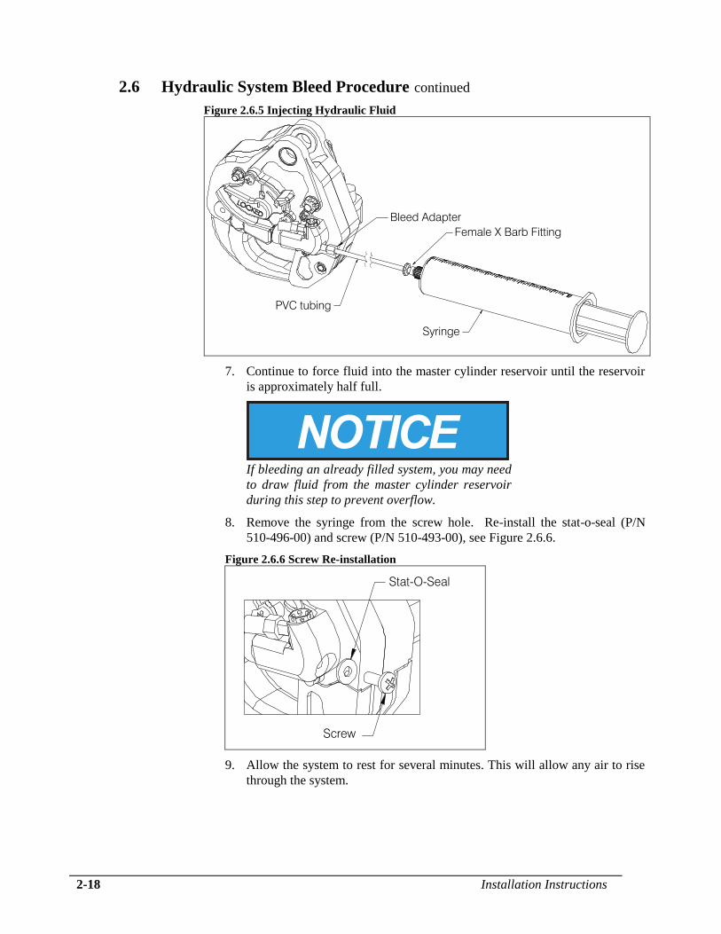
2.6 Hydraulic System Bleed Procedure continued
Figure 2.6.5 Injecting Hydraulic Fluid
Bleed Adapter
PVC tubing
Female X Barb Fitting
Syringe
7. Continue to force fluid into the master cylinder reservoir until the reservoir
is approximately half full.
If bleeding an already filled system, you may need
to draw fluid from the master cylinder reservoir
during this step to prevent overflow.
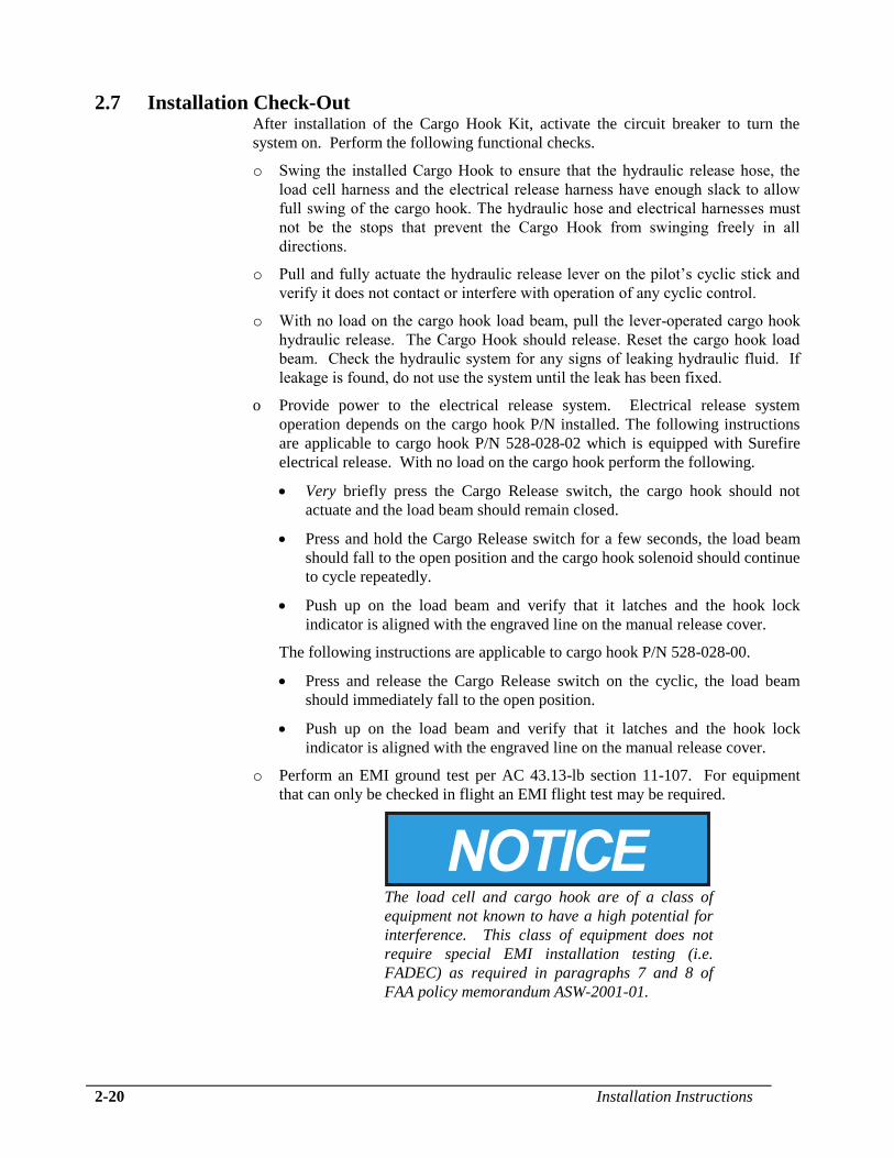
8. Remove the syringe from the screw hole. Re-install the stat-o-seal (P/N
510-496-00) and screw (P/N 510-493-00), see Figure 2.6.6.
Figure 2.6.6 Screw Re-installation
Stat-O-Seal
Screw
9. Allow the system to rest for several minutes. This will allow any air to rise
through the system.

Installation Instructions 2-19
2.6 Hydraulic System Bleed Procedure continued
10. Very slowly pull the release lever on the master cylinder and watch for
bubbles. If bubbles are observed rising within the reservoir, continue to
slowly cycle the lever until there are no more. Actuating the lever releases
air trapped within the master cylinder.
Pull the lever very slowly! When the reservoir is
not baffled and capped, a hard pull will cause
fluid to erupt over the edge of the reservoir.
11. Check the system for air by actuating the lever firmly until it bottoms out.
Check the push rod position (see Figure 2.6.7). If some of the green ring on
the push rod is visible, proceed to step 13. If none of the green ring on the
push rod is visible with the lever completely pulled, the system has too
much air in it and needs further bleeding. To do this, repeat steps 5 – 11.
Figure 2.6.7 Checking System for Air
Some of the green
ring must be visible.
12. After the system is properly bled, verify that the reservoir is approximately
half full of hydraulic fluid. Fluid should be visible above the baffle.
13. Re-install the baffle and the reservoir lid.
14. Check the system for proper operation. Fully actuate the release lever. The
hook must open and the lever must have a firm feel.
2-20 Installation Instructions
2.7 Installation Check-Out After installation of the Cargo Hook Kit, activate the circuit breaker to turn the
system on. Perform the following functional checks.
o Swing the installed Cargo Hook to ensure that the hydraulic release hose, the
load cell harness and the electrical release harness have enough slack to allow
full swing of the cargo hook. The hydraulic hose and electrical harnesses must
not be the stops that prevent the Cargo Hook from swinging freely in all
directions.
o Pull and fully actuate the hydraulic release lever on the pilot’s cyclic stick and
verify it does not contact or interfere with operation of any cyclic control.
o With no load on the cargo hook load beam, pull the lever-operated cargo hook
hydraulic release. The Cargo Hook should release. Reset the cargo hook load
beam. Check the hydraulic system for any signs of leaking hydraulic fluid. If
leakage is found, do not use the system until the leak has been fixed.
o Provide power to the electrical release system. Electrical release system
operation depends on the cargo hook P/N installed. The following instructions
are applicable to cargo hook P/N 528-028-02 which is equipped with Surefire
electrical release. With no load on the cargo hook perform the following.
Very briefly press the Cargo Release switch, the cargo hook should not
actuate and the load beam should remain closed.
Press and hold the Cargo Release switch for a few seconds, the load beam
should fall to the open position and the cargo hook solenoid should continue
to cycle repeatedly.
Push up on the load beam and verify that it latches and the hook lock
indicator is aligned with the engraved line on the manual release cover.
The following instructions are applicable to cargo hook P/N 528-028-00.
Press and release the Cargo Release switch on the cyclic, the load beam
should immediately fall to the open position.
Push up on the load beam and verify that it latches and the hook lock
indicator is aligned with the engraved line on the manual release cover.
o Perform an EMI ground test per AC 43.13-lb section 11-107. For equipment
that can only be checked in flight an EMI flight test may be required.
The load cell and cargo hook are of a class of
equipment not known to have a high potential for
interference. This class of equipment does not
require special EMI installation testing (i.e.
FADEC) as required in paragraphs 7 and 8 of
FAA policy memorandum ASW-2001-01.

Installation Instructions 2-21
2.7 Installation Check-Out continued
o In the US, fill in FAA form 337 for the initial installation. This procedure may
vary in different countries. Make the appropriate aircraft log book entry.
Insert the Rotorcraft Flight Manual Supplement 121-028-01 in the Rotorcraft
Flight Manual.
2.8 Component Weights The weights of the Cargo Hook Kit components are listed below.
Table 2.8.1 Component Weights
Item P/N 200-378-XX
Lbs (kg)
P/N 200-379-XX
Lbs (kg)
Cargo Hook 3.0 (1.36) 3.0 (1.36)
Cargo Hook attach hardware* 0.2 (.09) -
Slave Cylinder w/ Plumbing 0.30 (0.14) 0.30 (0.14)
Attach Point Assembly (includes Spacer
and mounting hardware)
1.23 (0.56) 1.23 (0.56)
Release Lever Assembly w/ Plumbing 0.67 (0.30) 0.67 (0.30)
Electrical Release Harness 0.5 (0.23) 0.5 (0.23)
Pin Load Cell Assembly - 0.40 (0.18)
C-39 Indicator - 0.47 (0.21)
Load Weigh Internal Harness - 0.54 (0.25)
Misc. hardware - 0.10 (0.04)
Total 5.90 (2.68) 7.21 (3.26)
* When Kit P/N 200-379-XX is installed, the cargo hook attach bolt is replaced by
the pin load cell assembly.
2.9 Cargo Hook Location
Table 2.9.1 Cargo Hook Location
Station 99.3

This page intentionally left blank.
Operation Instructions 3-1
Section 3
Operation Instructions Operating Procedures
Refer to Owner’s Manual No. 120-039-00 for detailed operation
instructions for the C-39 Load Weigh Indicator.
Prior to a flight involving external load operations perform the following:
1. Move the cargo hook throughout its range of motion and verify that the
hydraulic hose and electrical harness are not pulled tight, pinched or
otherwise damaged in any position.
2. Provide power to the electrical release system. Electrical release
system operation depends on the cargo hook P/N installed. The
following instructions are applicable to cargo hook P/N 528-028-02
which is equipped with Surefire electrical release. With no load on the
cargo hook perform the following.
Very briefly press the Cargo Release switch, the cargo hook should
not actuate and the load beam should remain closed.
Press and hold the Cargo Release switch for a few seconds, the load
beam should fall to the open position and the cargo hook solenoid
should continue to cycle repeatedly.
Push up on the load beam and verify that it latches and the hook
lock indicator is aligned with the engraved line on the manual
release cover.
The following instructions are applicable to cargo hook P/N 528-028-
00.
Press and release the Cargo Release switch on the cyclic, the load
beam should fall to the open position.
Push up on the load beam and verify that it latches and the hook
lock indicator is aligned with the engraved line on the manual
release cover.
The release solenoid is intended to be energized
only intermittently. Depressing the electrical
release button continuously in excess of 20
seconds will cause the release solenoid to
overheat, possibly causing permanent damage.
3-2 Operation Instructions
Operating Procedures continued 3. Activate the release lever assembly located on the cyclic stick to check
the function of the cargo hook hydraulic release. The load beam should
open. Reset the cargo hook load beam by hand after release. Verify
that the hook lock indicator on the side of the hook returns to the fully
locked position. If the hook does not release or re-latch, do not use the
unit until the problem is resolved.
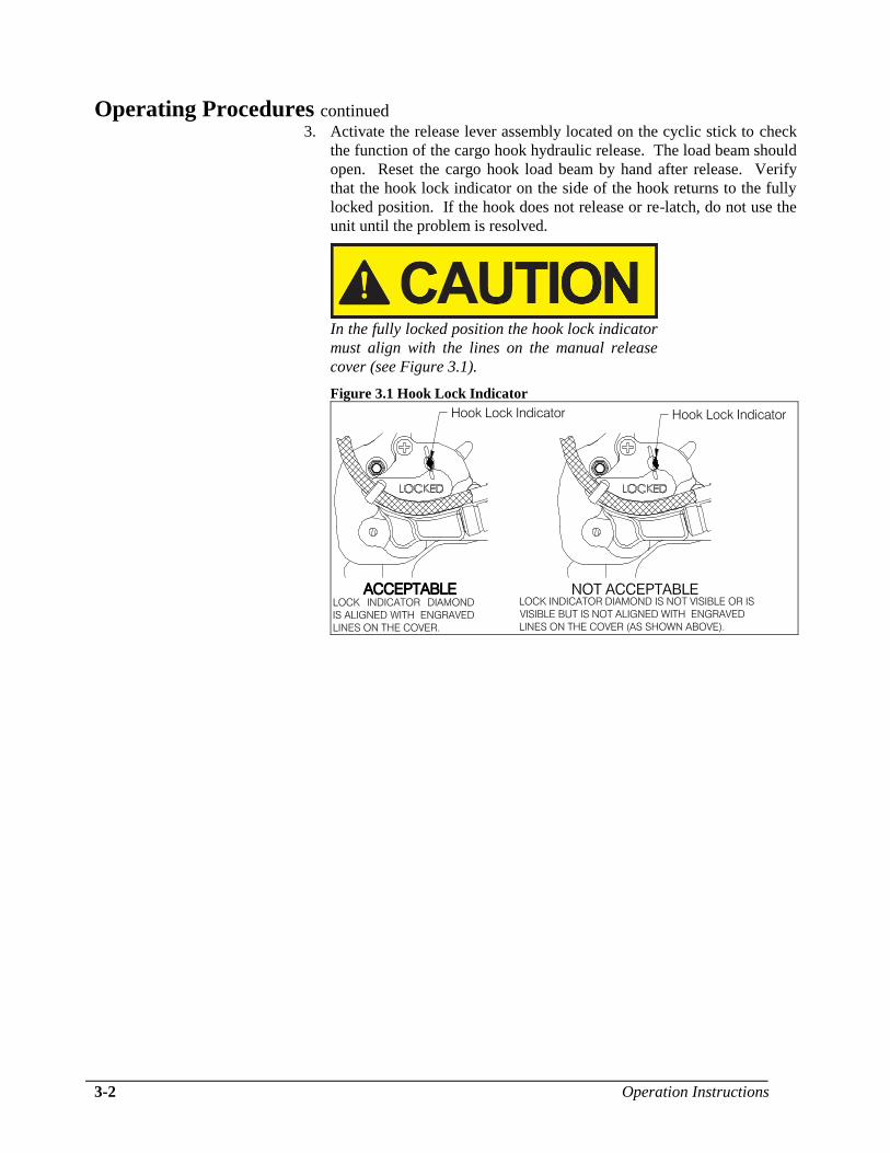
In the fully locked position the hook lock indicator
must align with the lines on the manual release
cover (see Figure 3.1).
Figure 3.1 Hook Lock Indicator
Hook Lock Indicator Hook Lock Indicator
ACCEPTABLE
Operation Instructions 3-3
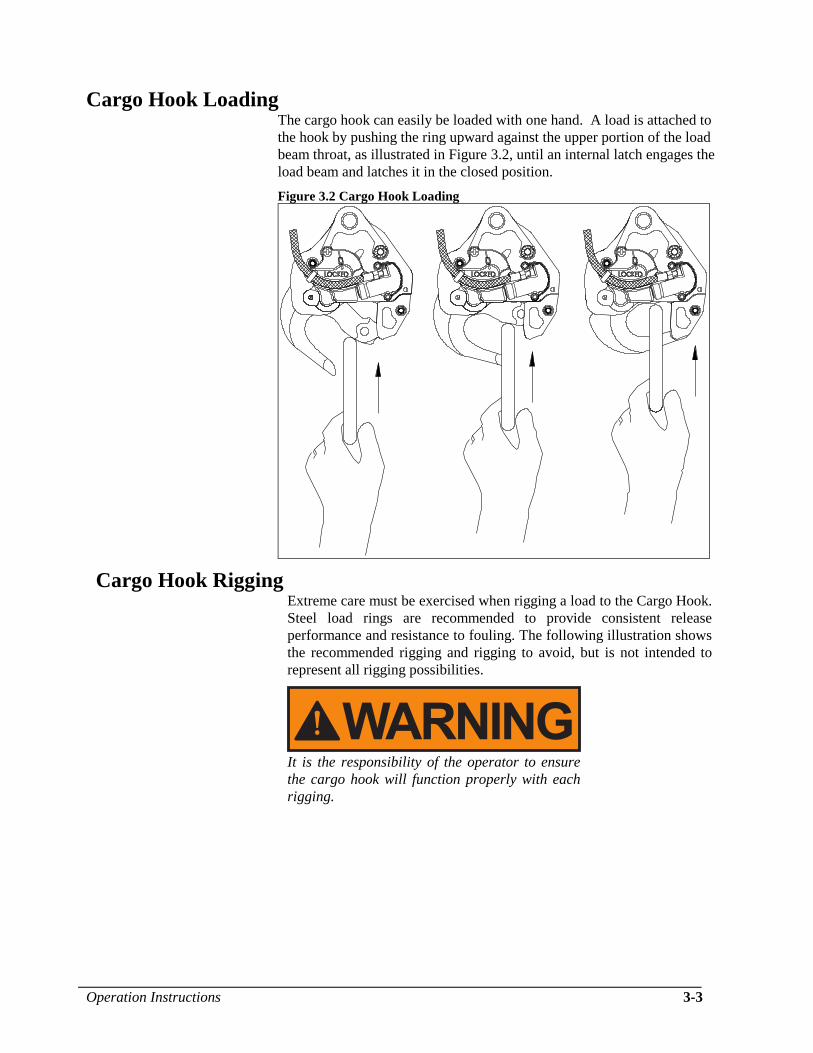
Cargo Hook Loading The cargo hook can easily be loaded with one hand. A load is attached to
the hook by pushing the ring upward against the upper portion of the load
beam throat, as illustrated in Figure 3.2, until an internal latch engages the
load beam and latches it in the closed position.
Figure 3.2 Cargo Hook Loading
Cargo Hook Rigging Extreme care must be exercised when rigging a load to the Cargo Hook.
Steel load rings are recommended to provide consistent release
performance and resistance to fouling. The following illustration shows
the recommended rigging and rigging to avoid, but is not intended to
represent all rigging possibilities.
It is the responsibility of the operator to ensure
the cargo hook will function properly with each
rigging.

3-4 Operation Instructions
Cargo Hook Rigging continued
Nylon type straps (or similar material) or rope
must not be used directly on the cargo hook load
beam. If nylon straps or rope must be used they
should be first attached to a steel primary ring.
Verify that the ring will freely slide off the load
beam when it is opened. Only the primary ring
should be in contact with the cargo hook load
beam.
Figure 3.3 Examples of Cargo Hook Rigging
Primary Ring
Long Line
Primary Ring
Long Line
Recommended Avoid
Maintenance 4-1
Section 4
Maintenance Refer to Component Maintenance Manual (CMM) 122-015-00 and
Instructions for Continued Airworthiness (ICA) 123-021-01 for detailed
maintenance information.
Instructions for Returning Equipment to the Factory If an Onboard Systems product must be returned to the factory for any
reason (including returns, service, repairs, overhaul, etc.) obtain an RMA
number before shipping your return.
An RMA number is required for all equipment
returns.
To obtain an RMA, please use one of the listed methods.
Contact Technical Support by phone or e-mail
Generate an RMA number at our website:
http://www.onboardsystems.com/rma.php
After you have obtained the RMA number, please be sure to:
Package the component carefully to ensure safe transit.
Write the RMA number on the outside of the box or on the mailing
label.
Include the RMA number and reason for the return on your
purchase or work order.
Include your name, address, phone and fax number and email (as
applicable).
Return the components freight, cartage, insurance and customs
prepaid to:
Onboard Systems
13915 NW 3rd Court
Vancouver, Washington 98685
USA
Phone: 360-546-3072

This page intentionally left blank.
Certification 5-1
Section 5
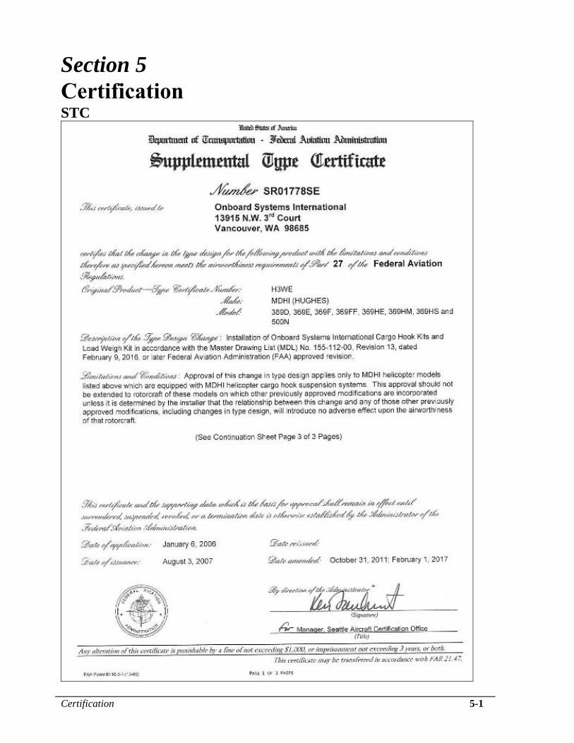
Certification STC

5-2 Certification
STC continued

Certification 5-3
Canadian Approval

5-4 Certification
ANAC STC
Certification 5-5
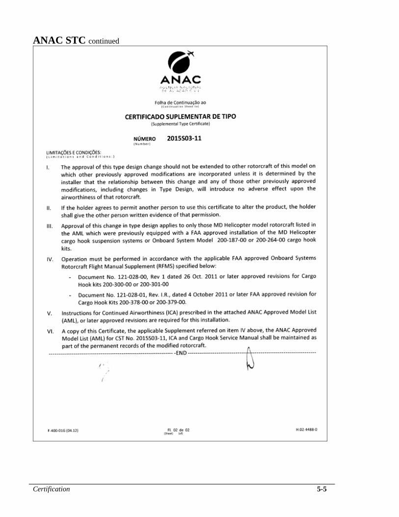
ANAC STC continued
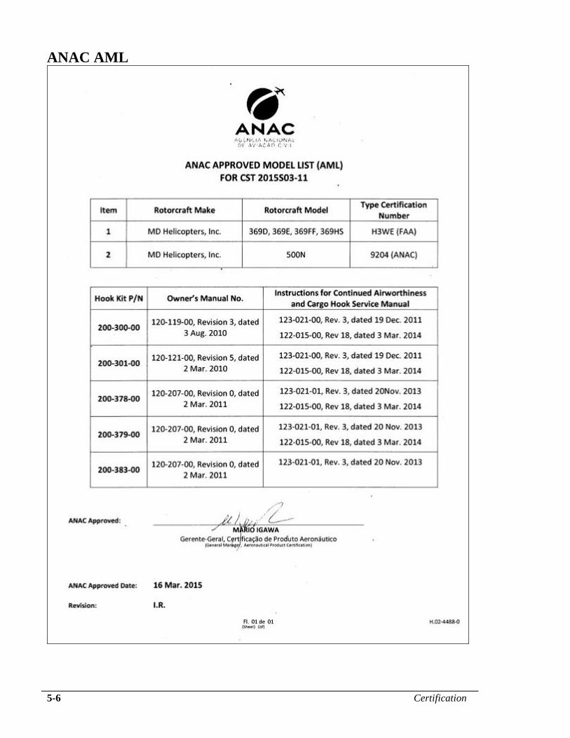
5-6 Certification
ANAC AML