system surgical technique - the royal children's … · 1.8mm, 3.6mm, and 5.2mm angled...
TRANSCRIPT

METRx® System
Surgical Technique
The METRx® System allows access to the spine using a series of sequential muscle dilation tubes. This dilation approach causes less disruption to the surrounding muscles and also allows the paraspinous muscles to remain attached to the spinous process.
The minimally invasive implants and instruments require smaller incisions than traditional open surgery and are designed for muscle-sparing approaches.

Table of Contents
METRx® System
Surgical Technique
Instrument Set 2
Tubular Retraction 6
Spinal Fusion 8
Posterior Foraminotomy 10
Lumbar Stenosis 12
Discectomy 14
TLIF Procedure 16
PLIF Procedure 18
Product Ordering Information 20
Important Product Information 23

Instrument Set
2mm Straight and Upbiting Micropituitary
2mm Pituitary with Tooth
Curved Scissors(Standard and Microsizes Available)
4mm Straight and Upbiting Pituitary
2mm Upbiting and Downbiting Pituitary
Suction Retractor
Nerve Hooks – Straight, Left, and Right (Standard and Microsizes Available)
Wide Nerve Root Retractor
Nerve Root Retractor
Bayoneted Bipolar Forceps (Standard and Microsizes Available)
Angled Bipolar Forceps (Standard and Microsizes Available)
90° Ball Probes Long and Short, Left, Right, and Straight
45° Woodson Probe
Reverse Angled Curettes1.8mm, 3.6mm, and 5.2mm
Angled Curettes1.8mm, 3.6mm, and 5.2mm
Straight Curettes1.8mm, 3.6mm, and 5.2mm
90° DissectorsLeft, Right, and Straight
Penfield Push and Pull(#2, #4, and #7 Sizes Available)
METRx® System | Surgical Technique2 METRx® System | Surgical Technique
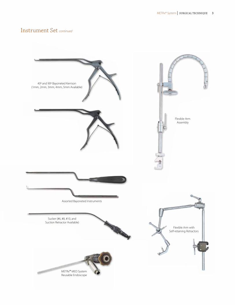
Instrument Set continued
Flexible ArmAssembly
Flexible Arm with Self-retaining Retractors
40º and 90º Bayoneted Kerrison(1mm, 2mm, 3mm, 4mm, 5mm Available)
Assorted Bayoneted Instruments
Sucker (#6, #8, #10, and Suction Retractor Available)
METRx® MED System Reusable Endoscope
METRx® System | Surgical Technique METRx® System | Surgical Technique 3
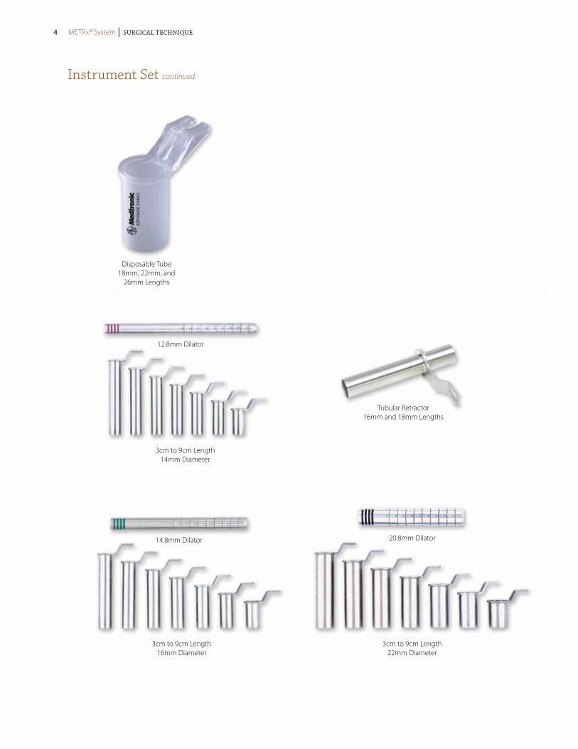
Instrument Set continued
12.8mm Dilator
3cm to 9cm Length14mm Diameter
14.8mm Dilator
3cm to 9cm Length16mm Diameter
20.8mm Dilator
3cm to 9cm Length22mm Diameter
Tubular Retractor16mm and 18mm Lengths
Disposable Tube18mm, 22mm, and
26mm Lengths
METRx® System | Surgical Technique4 METRx® System | Surgical Technique

Instrument Set continued
METRx® X-TUBE™ Retraction System4cm to 8cm Length
26mm Diameter
16.8mm Dilator
3cm to 9cm Length18mm Diameter
18.8mm Dilator
3cm to 9cm Length20mm Diameter
22.8mm Dilator
24.8mm Dilator
3cm to 9cm Length26mm Diameter
.062mm × 12" Guidewire
9.4mm Dilator
5.3mm Dilator
24.8mm Dilator
METRx® System | Surgical Technique METRx® System | Surgical Technique 5
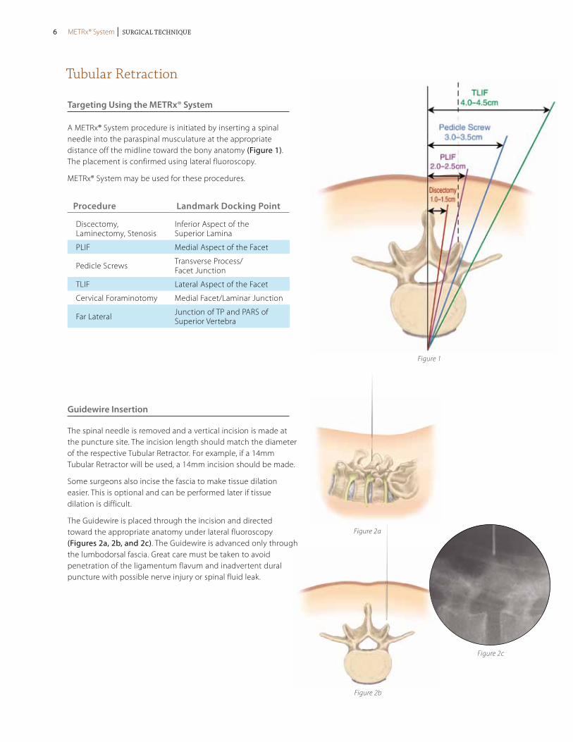
Tubular Retraction
Targeting Using the METRx® System
Guidewire Insertion
A METRx® System procedure is initiated by inserting a spinal needle into the paraspinal musculature at the appropriate distance off the midline toward the bony anatomy (Figure 1). The placement is confirmed using lateral fluoroscopy.
METRx® System may be used for these procedures.
The spinal needle is removed and a vertical incision is made at the puncture site. The incision length should match the diameter of the respective Tubular Retractor. For example, if a 14mm Tubular Retractor will be used, a 14mm incision should be made.
Some surgeons also incise the fascia to make tissue dilation easier. This is optional and can be performed later if tissue dilation is difficult.
The Guidewire is placed through the incision and directed toward the appropriate anatomy under lateral fluoroscopy (Figures 2a, 2b, and 2c). The Guidewire is advanced only through the lumbodorsal fascia. Great care must be taken to avoid penetration of the ligamentum flavum and inadvertent dural puncture with possible nerve injury or spinal fluid leak.
Figure 1
Figure 2a
Figure 2b
Figure 2c
Procedure Landmark Docking Point
Discectomy, Laminectomy, Stenosis
Inferior Aspect of the Superior Lamina
PLIF Medial Aspect of the Facet
Pedicle Screws Transverse Process/ Facet Junction
TLIF Lateral Aspect of the Facet
Cervical Foraminotomy Medial Facet/Laminar Junction
Far Lateral Junction of TP and PARS of Superior Vertebra
METRx® System | Surgical Technique6 METRx® System | Surgical Technique
Tubular Retraction continued
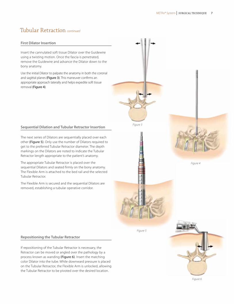
Insert the cannulated soft tissue Dilator over the Guidewire using a twisting motion. Once the fascia is penetrated, remove the Guidewire and advance the Dilator down to the bony anatomy.
Use the initial Dilator to palpate the anatomy in both the coronal and sagittal planes (Figure 3). This maneuver confirms an appropriate approach laterally and helps expedite soft tissue removal (Figure 4).
First Dilator Insertion
Sequential Dilation and Tubular Retractor Insertion
Repositioning the Tubular Retractor
If repositioning of the Tubular Retractor is necessary, the Retractor can be moved or angled over the pathology by a process known as wanding (Figure 6). Insert the matching color Dilator into the tube. While downward pressure is placed on the Tubular Retractor, the Flexible Arm is unlocked, allowing the Tubular Retractor to be pivoted over the desired location.
The next series of Dilators are sequentially placed over each other (Figure 5). Only use the number of Dilators required to get to the preferred Tubular Retractor diameter. The depth markings on the Dilators are noted to indicate the Tubular Retractor length appropriate to the patient’s anatomy.
The appropriate Tubular Retractor is placed over the sequential Dilators and seated firmly on the bony anatomy. The Flexible Arm is attached to the bed rail and the selected Tubular Retractor.
The Flexible Arm is secured and the sequential Dilators are removed, establishing a tubular operative corridor.
Figure 3
Figure 4
Figure 5
Figure 6
METRx® System | Surgical Technique METRx® System | Surgical Technique 7

Spinal Fusion Procedure utilizing METRx® X-TubE® Retraction System
For complete instructions of use for the implant system, please refer to the appropriate surgical technique and package insert.
Tube Introduction
The METRx® X-TUBE® Instrument is selected in accordance with exposed markings on the final Dilator (Figure 7). The Tube is then inserted over the Dilators and seated firmly flush with the bony anatomy and locked in place with the Flexible Arm. The Dilators are then removed establishing a tubular operative corridor.
Tube Deployment
The METRx® X-TUBE® Instrument is expanded using the Opener instrument. Insert the Opener into the tube with the instrument stops facing medial/lateral and squeeze the handles (Figure 8). The tube will remain in the expanded position until the hinges are released.
Pedicle Preparation
Inferior and superior pedicles may now be targeted (Figure 9).
Screw Insertion
Tap and insert the Pedicle Screw (Figure 10).
Figure 7
Figure 9
Figure 8
Figure 10
METRx® System | Surgical Technique8 METRx® System | Surgical Technique
Spinal Fusion Procedure utilizing METRx® X-TubE® Retraction System continued
For complete instructions of use for the implant system, please refer to the appropriate surgical technique and package insert.
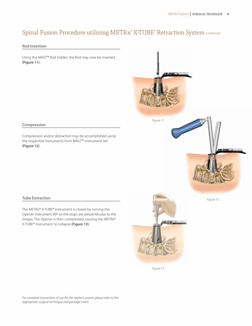
Rod Insertion
Using the MAST™ Rod Holder, the Rod may now be inserted (Figure 11).
Compression
Compression and/or distraction may be accomplished using the respective instruments from MAST™ Instrument Set (Figure 12).
Tube Extraction
The METRx® X-TUBE® Instrument is closed by turning the Opener instrument 90º so the stops are perpendicular to the hinges. The Opener is then compressed, causing the METRx® X-TUBE® Instrument to collapse (Figure 13).
Figure 11
Figure 13
Figure 12
METRx® System | Surgical Technique METRx® System | Surgical Technique 9
Posterior Cervical Foraminotomy utilizing METRx® System
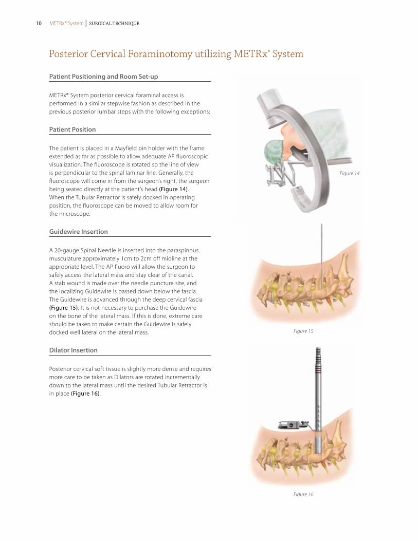
Patient Positioning and Room Set-up
METRx® System posterior cervical foraminal access is performed in a similar stepwise fashion as described in the previous posterior lumbar steps with the following exceptions:
Patient Position
The patient is placed in a Mayfield pin holder with the frame extended as far as possible to allow adequate AP fluoroscopic visualization. The fluoroscope is rotated so the line of view is perpendicular to the spinal laminar line. Generally, the fluoroscope will come in from the surgeon’s right, the surgeon being seated directly at the patient’s head (Figure 14). When the Tubular Retractor is safely docked in operating position, the fluoroscope can be moved to allow room for the microscope.
Guidewire Insertion
A 20-gauge Spinal Needle is inserted into the paraspinous musculature approximately 1cm to 2cm off midline at the appropriate level. The AP fluoro will allow the surgeon to safely access the lateral mass and stay clear of the canal. A stab wound is made over the needle puncture site, and the localizing Guidewire is passed down below the fascia. The Guidewire is advanced through the deep cervical fascia (Figure 15). It is not necessary to purchase the Guidewire on the bone of the lateral mass. If this is done, extreme care should be taken to make certain the Guidewire is safely docked well lateral on the lateral mass.
Dilator Insertion
Posterior cervical soft tissue is slightly more dense and requires more care to be taken as Dilators are rotated incrementally down to the lateral mass until the desired Tubular Retractor is in place (Figure 16).
Figure 14
Figure 15
Figure 16
METRx® System | Surgical Technique10 METRx® System | Surgical Technique
Posterior Cervical Foraminotomy utilizing METRx® System continued
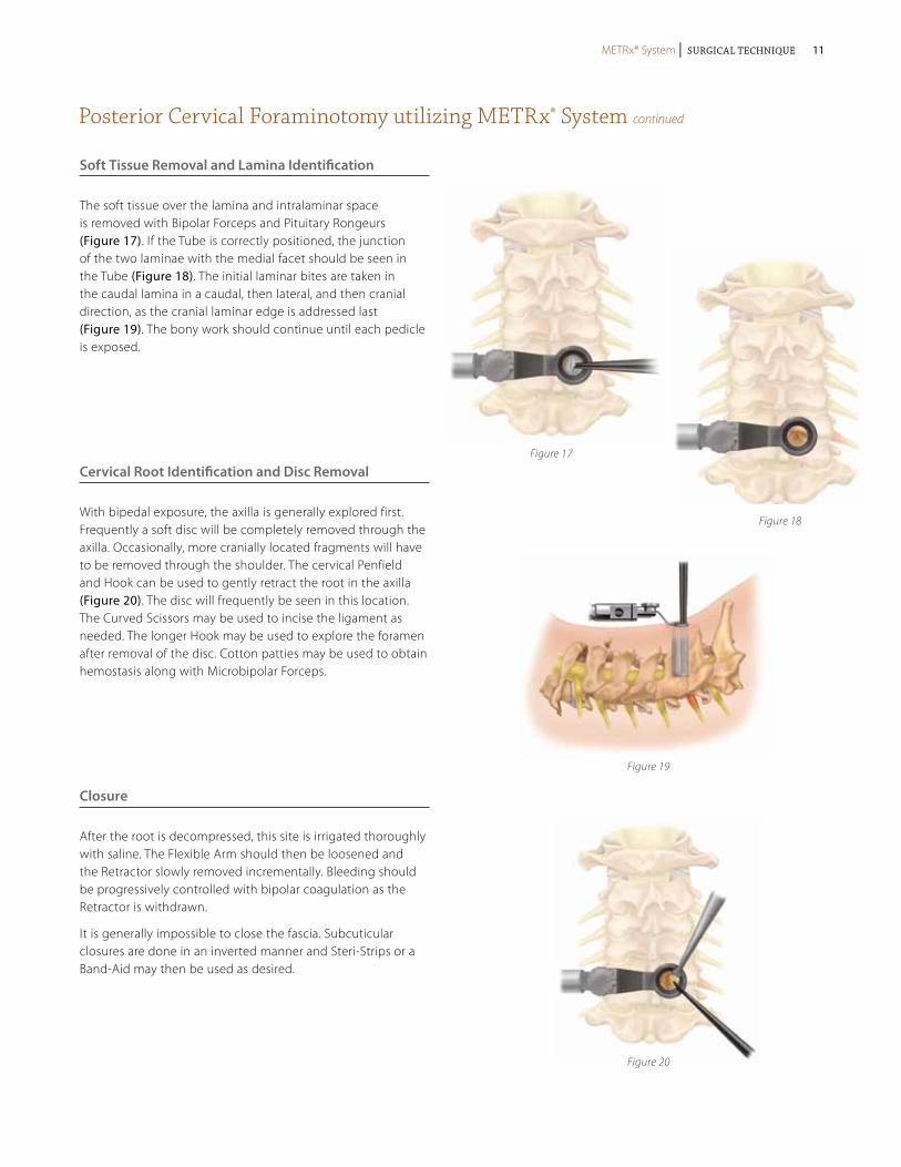
Soft Tissue Removal and Lamina Identification
The soft tissue over the lamina and intralaminar space is removed with Bipolar Forceps and Pituitary Rongeurs (Figure 17). If the Tube is correctly positioned, the junction of the two laminae with the medial facet should be seen in the Tube (Figure 18). The initial laminar bites are taken in the caudal lamina in a caudal, then lateral, and then cranial direction, as the cranial laminar edge is addressed last (Figure 19). The bony work should continue until each pedicle is exposed.
Cervical Root Identification and Disc Removal
With bipedal exposure, the axilla is generally explored first. Frequently a soft disc will be completely removed through the axilla. Occasionally, more cranially located fragments will have to be removed through the shoulder. The cervical Penfield and Hook can be used to gently retract the root in the axilla (Figure 20). The disc will frequently be seen in this location. The Curved Scissors may be used to incise the ligament as needed. The longer Hook may be used to explore the foramen after removal of the disc. Cotton patties may be used to obtain hemostasis along with Microbipolar Forceps.
Closure
After the root is decompressed, this site is irrigated thoroughly with saline. The Flexible Arm should then be loosened and the Retractor slowly removed incrementally. Bleeding should be progressively controlled with bipolar coagulation as the Retractor is withdrawn.
It is generally impossible to close the fascia. Subcuticular closures are done in an inverted manner and Steri-Strips or a Band-Aid may then be used as desired.
Figure 17
Figure 18
Figure 19
Figure 20
METRx® System | Surgical Technique METRx® System | Surgical Technique 11
Lumbar Stenosis utilizing METRx® System
Decompression
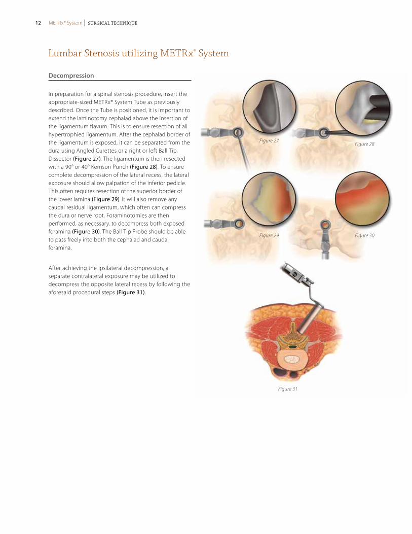
In preparation for a spinal stenosis procedure, insert the appropriate-sized METRx® System Tube as previously described. Once the Tube is positioned, it is important to extend the laminotomy cephalad above the insertion of the ligamentum flavum. This is to ensure resection of all hypertrophied ligamentum. After the cephalad border of the ligamentum is exposed, it can be separated from the dura using Angled Curettes or a right or left Ball Tip Dissector (Figure 27). The ligamentum is then resected with a 90° or 40° Kerrison Punch (Figure 28). To ensure complete decompression of the lateral recess, the lateral exposure should allow palpation of the inferior pedicle. This often requires resection of the superior border of the lower lamina (Figure 29). It will also remove any caudal residual ligamentum, which often can compress the dura or nerve root. Foraminotomies are then performed, as necessary, to decompress both exposed foramina (Figure 30). The Ball Tip Probe should be able to pass freely into both the cephalad and caudal foramina.
After achieving the ipsilateral decompression, a separate contralateral exposure may be utilized to decompress the opposite lateral recess by following the aforesaid procedural steps (Figure 31).
Figure 27Figure 28
Figure 29
Figure 31
Figure 30
METRx® System | Surgical Technique12 METRx® System | Surgical Technique
Lumbar Stenosis utilizing METRx® System continued
Figure 33a
Figure 32Figure 32
Figure 33a
Figure 33b
Figure 33c
Figure 34
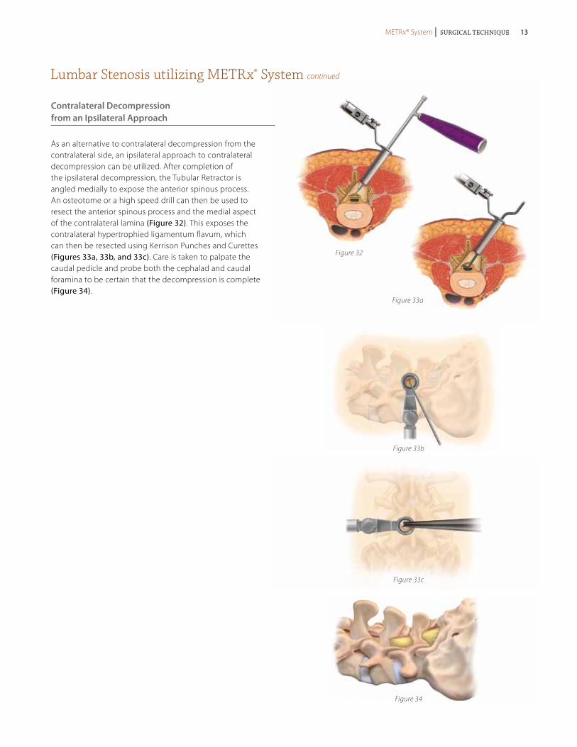
Contralateral Decompression from an Ipsilateral Approach
As an alternative to contralateral decompression from the contralateral side, an ipsilateral approach to contralateral decompression can be utilized. After completion of the ipsilateral decompression, the Tubular Retractor is angled medially to expose the anterior spinous process. An osteotome or a high speed drill can then be used to resect the anterior spinous process and the medial aspect of the contralateral lamina (Figure 32). This exposes the contralateral hypertrophied ligamentum flavum, which can then be resected using Kerrison Punches and Curettes (Figures 33a, 33b, and 33c). Care is taken to palpate the caudal pedicle and probe both the cephalad and caudal foramina to be certain that the decompression is complete (Figure 34).
METRx® System | Surgical Technique METRx® System | Surgical Technique 13
Discectomy utilizing the METRx® System
Soft Tissue Removal and Laminar Identification
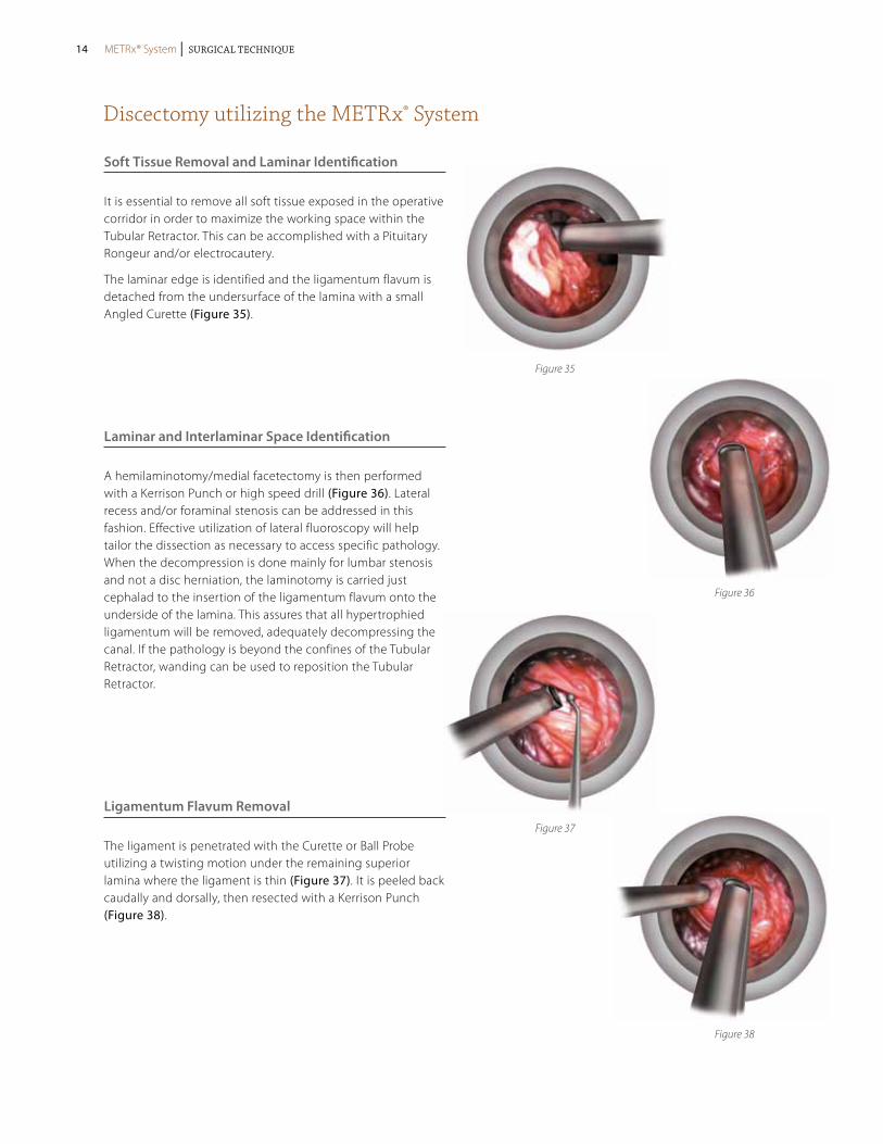
It is essential to remove all soft tissue exposed in the operative corridor in order to maximize the working space within the Tubular Retractor. This can be accomplished with a Pituitary Rongeur and/or electrocautery.
The laminar edge is identified and the ligamentum flavum is detached from the undersurface of the lamina with a small Angled Curette (Figure 35).
Laminar and Interlaminar Space Identification
A hemilaminotomy/medial facetectomy is then performed with a Kerrison Punch or high speed drill (Figure 36). Lateral recess and/or foraminal stenosis can be addressed in this fashion. Effective utilization of lateral fluoroscopy will help tailor the dissection as necessary to access specific pathology. When the decompression is done mainly for lumbar stenosis and not a disc herniation, the laminotomy is carried just cephalad to the insertion of the ligamentum flavum onto the underside of the lamina. This assures that all hypertrophied ligamentum will be removed, adequately decompressing the canal. If the pathology is beyond the confines of the Tubular Retractor, wanding can be used to reposition the Tubular Retractor.
Ligamentum Flavum Removal
The ligament is penetrated with the Curette or Ball Probe utilizing a twisting motion under the remaining superior lamina where the ligament is thin (Figure 37). It is peeled back caudally and dorsally, then resected with a Kerrison Punch (Figure 38).
Figure 35
Figure 36
Figure 37
Figure 38
METRx® System | Surgical Technique14 METRx® System | Surgical Technique
Discectomy utilizing the METRx® System continued
Nerve Root Exploration and Retraction
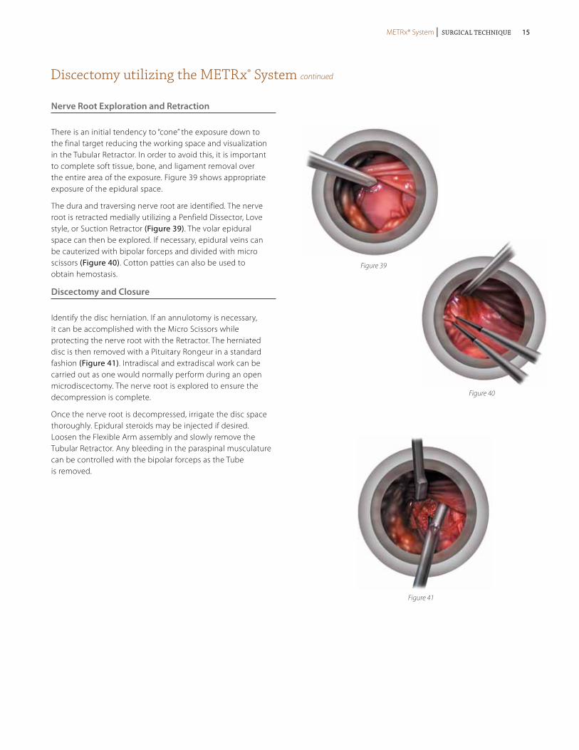
There is an initial tendency to “cone” the exposure down to the final target reducing the working space and visualization in the Tubular Retractor. In order to avoid this, it is important to complete soft tissue, bone, and ligament removal over the entire area of the exposure. Figure 39 shows appropriate exposure of the epidural space.
The dura and traversing nerve root are identified. The nerve root is retracted medially utilizing a Penfield Dissector, Love style, or Suction Retractor (Figure 39). The volar epidural space can then be explored. If necessary, epidural veins can be cauterized with bipolar forceps and divided with micro scissors (Figure 40). Cotton patties can also be used to obtain hemostasis.
Discectomy and Closure
Identify the disc herniation. If an annulotomy is necessary, it can be accomplished with the Micro Scissors while protecting the nerve root with the Retractor. The herniated disc is then removed with a Pituitary Rongeur in a standard fashion (Figure 41). Intradiscal and extradiscal work can be carried out as one would normally perform during an open microdiscectomy. The nerve root is explored to ensure the decompression is complete.
Once the nerve root is decompressed, irrigate the disc space thoroughly. Epidural steroids may be injected if desired. Loosen the Flexible Arm assembly and slowly remove the Tubular Retractor. Any bleeding in the paraspinal musculature can be controlled with the bipolar forceps as the Tube is removed.
Figure 39
Figure 40
Figure 41
METRx® System | Surgical Technique METRx® System | Surgical Technique 15
For complete instructions of use for the implant system, please refer to the appropriate surgical technique and package insert.
TLIF Procedure Overview utilizing METRx® System and CD HORIZON® SEXTANT® II Percutaneous Rod System
Figure 43
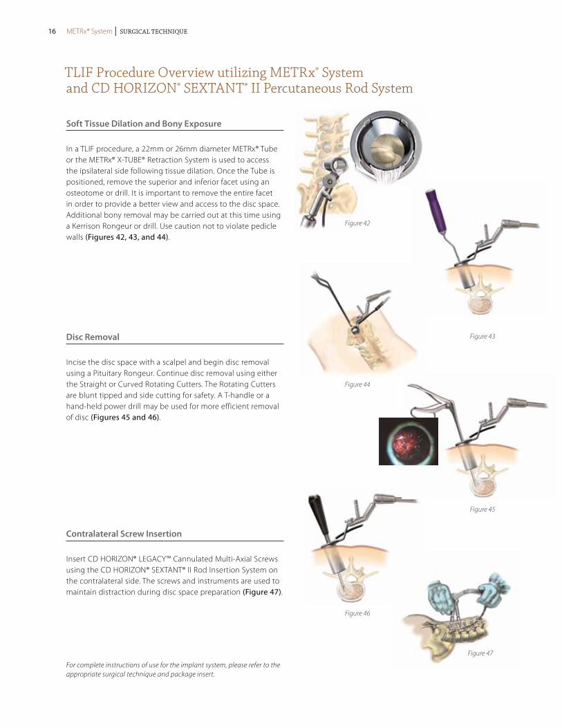
Soft Tissue Dilation and Bony Exposure
In a TLIF procedure, a 22mm or 26mm diameter METRx® Tube or the METRx® X-TUBE® Retraction System is used to access the ipsilateral side following tissue dilation. Once the Tube is positioned, remove the superior and inferior facet using an osteotome or drill. It is important to remove the entire facet in order to provide a better view and access to the disc space. Additional bony removal may be carried out at this time using a Kerrison Rongeur or drill. Use caution not to violate pedicle walls (Figures 42, 43, and 44).
Disc Removal
Incise the disc space with a scalpel and begin disc removal using a Pituitary Rongeur. Continue disc removal using either the Straight or Curved Rotating Cutters. The Rotating Cutters are blunt tipped and side cutting for safety. A T-handle or a hand-held power drill may be used for more efficient removal of disc (Figures 45 and 46).
Contralateral Screw Insertion
Insert CD HORIZON® LEGACY™ Cannulated Multi-Axial Screws using the CD HORIZON® SEXTANT® II Rod Insertion System on the contralateral side. The screws and instruments are used to maintain distraction during disc space preparation (Figure 47).
Figure 42
Figure 46
Figure 44
Figure 45
Figure 47
METRx® System | Surgical Technique16 METRx® System | Surgical Technique
For complete instructions of use for the implant system, please refer to the appropriate surgical technique and package insert.
TLIF Procedure Overview utilizing METRx® System and CD HORIZON® SEXTANT® II Percutaneous Rod System continued
Figure 48
Figure 49
Figure 50
Figure 52
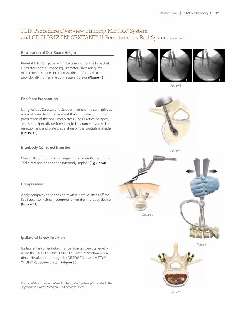
Restoration of Disc Space Height
Re-establish disc space height by using either the Impacted Distractors or the Expanding Distractor. Once adequate distraction has been obtained via the interbody space, provisionally tighten the contralateral Screws (Figure 48).
End Plate Preparation
Using various Curettes and Scrapers, remove the cartilaginous material from the disc space and the end plates. Continue preparation of the bony end plates using Curettes, Scrapers, and Rasps. Specially designed angled instruments allow disc resection and end plate preparation on the contralateral side (Figure 49).
Interbody Construct Insertion
Choose the appropriate size implant based on the use of the Trial Sizers and position the interbody implant (Figure 50).
Compression
Apply compression to the contralateral Screws. Break off the Set Screws to maintain compression on the interbody device (Figure 51).
Ipsilateral Screw Insertion
Ipsilateral instrumentation may be inserted percutaneously using the CD HORIZON® SEXTANT® II instrumentation or via direct visualization through the METRx® Tube and METRx® X-TUBE® Retraction System (Figure 52).
Figure 51
METRx® System | Surgical Technique METRx® System | Surgical Technique 17
PLIF Procedure Overview utilizing METRx® System
For complete instructions of use for the implant system, please refer to the appropriate surgical technique and package insert.
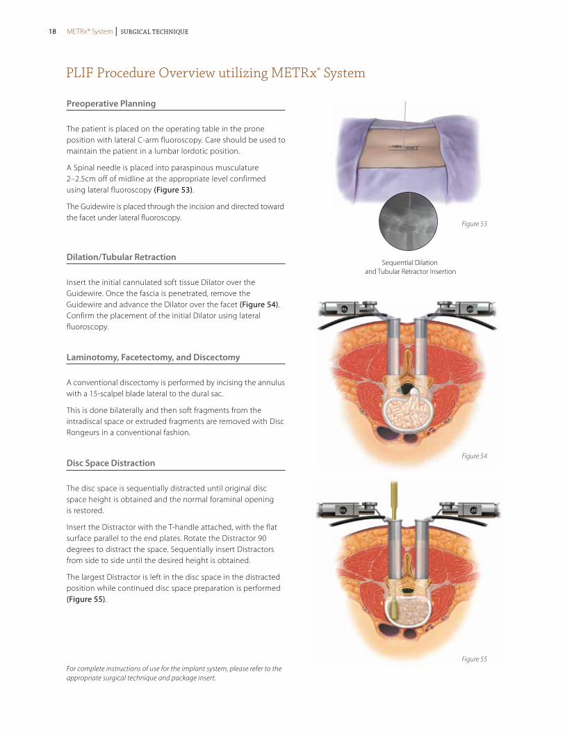
Preoperative Planning
The patient is placed on the operating table in the prone position with lateral C-arm fluoroscopy. Care should be used to maintain the patient in a lumbar lordotic position.
A Spinal needle is placed into paraspinous musculature 2–2.5cm off of midline at the appropriate level confirmed using lateral fluoroscopy (Figure 53).
The Guidewire is placed through the incision and directed toward the facet under lateral fluoroscopy.
Dilation/Tubular Retraction
Insert the initial cannulated soft tissue Dilator over the Guidewire. Once the fascia is penetrated, remove the Guidewire and advance the Dilator over the facet (Figure 54). Confirm the placement of the initial Dilator using lateral fluoroscopy.
Laminotomy, Facetectomy, and Discectomy
A conventional discectomy is performed by incising the annulus with a 15-scalpel blade lateral to the dural sac.
This is done bilaterally and then soft fragments from the intradiscal space or extruded fragments are removed with Disc Rongeurs in a conventional fashion.
Disc Space Distraction
The disc space is sequentially distracted until original disc space height is obtained and the normal foraminal opening is restored.
Insert the Distractor with the T-handle attached, with the flat surface parallel to the end plates. Rotate the Distractor 90 degrees to distract the space. Sequentially insert Distractors from side to side until the desired height is obtained.
The largest Distractor is left in the disc space in the distracted position while continued disc space preparation is performed (Figure 55).
Sequential Dilation and Tubular Retractor Insertion
Figure 53
Figure 54
Figure 55
METRx® System | Surgical Technique18 METRx® System | Surgical Technique
PLIF Procedure Overview utilizing METRx® System continued
For complete instructions of use for the implant system, please refer to the appropriate surgical technique and package insert.
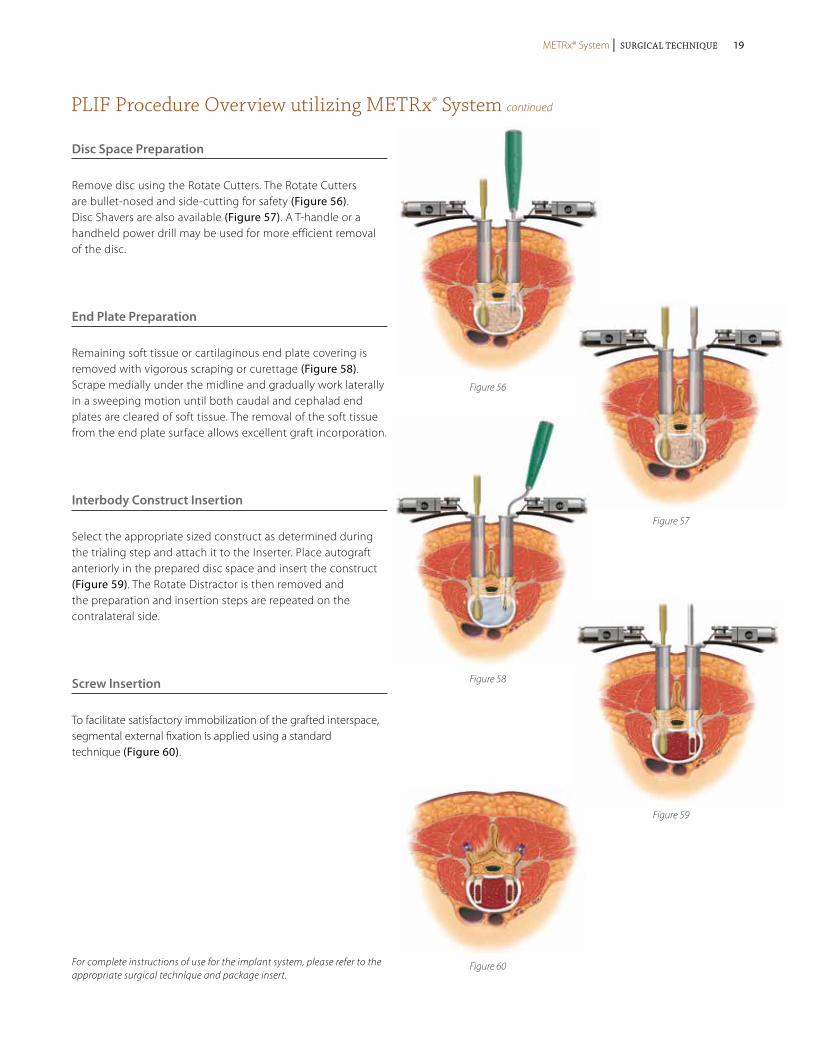
Disc Space Preparation
Remove disc using the Rotate Cutters. The Rotate Cutters are bullet-nosed and side-cutting for safety (Figure 56). Disc Shavers are also available (Figure 57). A T-handle or a handheld power drill may be used for more efficient removal of the disc.
End Plate Preparation
Remaining soft tissue or cartilaginous end plate covering is removed with vigorous scraping or curettage (Figure 58). Scrape medially under the midline and gradually work laterally in a sweeping motion until both caudal and cephalad end plates are cleared of soft tissue. The removal of the soft tissue from the end plate surface allows excellent graft incorporation.
Interbody Construct Insertion
Select the appropriate sized construct as determined during the trialing step and attach it to the Inserter. Place autograft anteriorly in the prepared disc space and insert the construct (Figure 59). The Rotate Distractor is then removed and the preparation and insertion steps are repeated on the contralateral side.
Screw Insertion
To facilitate satisfactory immobilization of the grafted interspace, segmental external fixation is applied using a standard technique (Figure 60).
Figure 56
Figure 57
Figure 60
Figure 58
Figure 59
METRx® System | Surgical Technique METRx® System | Surgical Technique 19
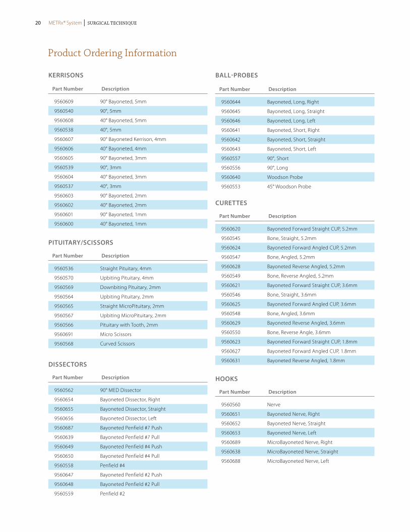
Product Ordering Information
KERRISoNS
Part Number Description
9560609 90° Bayoneted, 5mm
9560540 90°, 5mm
9560608 40° Bayoneted, 5mm
9560538 40°, 5mm
9560607 90° Bayoneted Kerrison, 4mm
9560606 40° Bayoneted, 4mm
9560605 90° Bayoneted, 3mm
9560539 90°, 3mm
9560604 40° Bayoneted, 3mm
9560537 40°, 3mm
9560603 90° Bayoneted, 2mm
9560602 40° Bayoneted, 2mm
9560601 90° Bayoneted, 1mm
9560600 40° Bayoneted, 1mm
Part Number Description
9560536 Straight Pituitary, 4mm
9560570 Upbiting Pituitary, 4mm
9560569 Downbiting Pituitary, 2mm
9560564 Upbiting Pituitary, 2mm
9560565 Straight MicroPituitary, 2mm
9560567 Upbiting MicroPituitary, 2mm
9560566 Pituitary with Tooth, 2mm
9560691 Micro Scissors
9560568 Curved Scissors
PITUITARy/SCISSoRS
Part Number Description
9560562 90° MED Dissector
9560654 Bayoneted Dissector, Right
9560655 Bayoneted Dissector, Straight
9560656 Bayoneted Dissector, Left
9560687 Bayoneted Penfield #7 Push
9560639 Bayoneted Penfield #7 Pull
9560649 Bayoneted Penfield #4 Push
9560650 Bayoneted Penfield #4 Pull
9560558 Penfield #4
9560647 Bayoneted Penfield #2 Push
9560648 Bayoneted Penfield #2 Pull
9560559 Penfield #2
DISSECToRS
Part Number Description
9560644 Bayoneted, Long, Right
9560645 Bayoneted, Long, Straight
9560646 Bayoneted, Long, Left
9560641 Bayoneted, Short, Right
9560642 Bayoneted, Short, Straight
9560643 Bayoneted, Short, Left
9560557 90°, Short
9560556 90°, Long
9560640 Woodson Probe
9560553 45° Woodson Probe
BALL-PRoBES
Part Number Description
9560620 Bayoneted Forward Straight CUP, 5.2mm
9560545 Bone, Straight, 5.2mm
9560624 Bayoneted Forward Angled CUP, 5.2mm
9560547 Bone, Angled, 5.2mm
9560628 Bayoneted Reverse Angled, 5.2mm
9560549 Bone, Reverse Angled, 5.2mm
9560621 Bayoneted Forward Straight CUP, 3.6mm
9560546 Bone, Straight, 3.6mm
9560625 Bayoneted Forward Angled CUP, 3.6mm
9560548 Bone, Angled, 3.6mm
9560629 Bayoneted Reverse Angled, 3.6mm
9560550 Bone, Reverse Angle, 3.6mm
9560623 Bayoneted Forward Straight CUP, 1.8mm
9560627 Bayoneted Forward Angled CUP, 1.8mm
9560631 Bayoneted Reverse Angled, 1.8mm
CURETTES
Part Number Description
9560560 Nerve
9560651 Bayoneted Nerve, Right
9560652 Bayoneted Nerve, Straight
9560653 Bayoneted Nerve, Left
9560689 MicroBayoneted Nerve, Right
9560638 MicroBayoneted Nerve, Straight
9560688 MicroBayoneted Nerve, Left
HooKS
METRx® System | Surgical Technique20 METRx® System | Surgical Technique
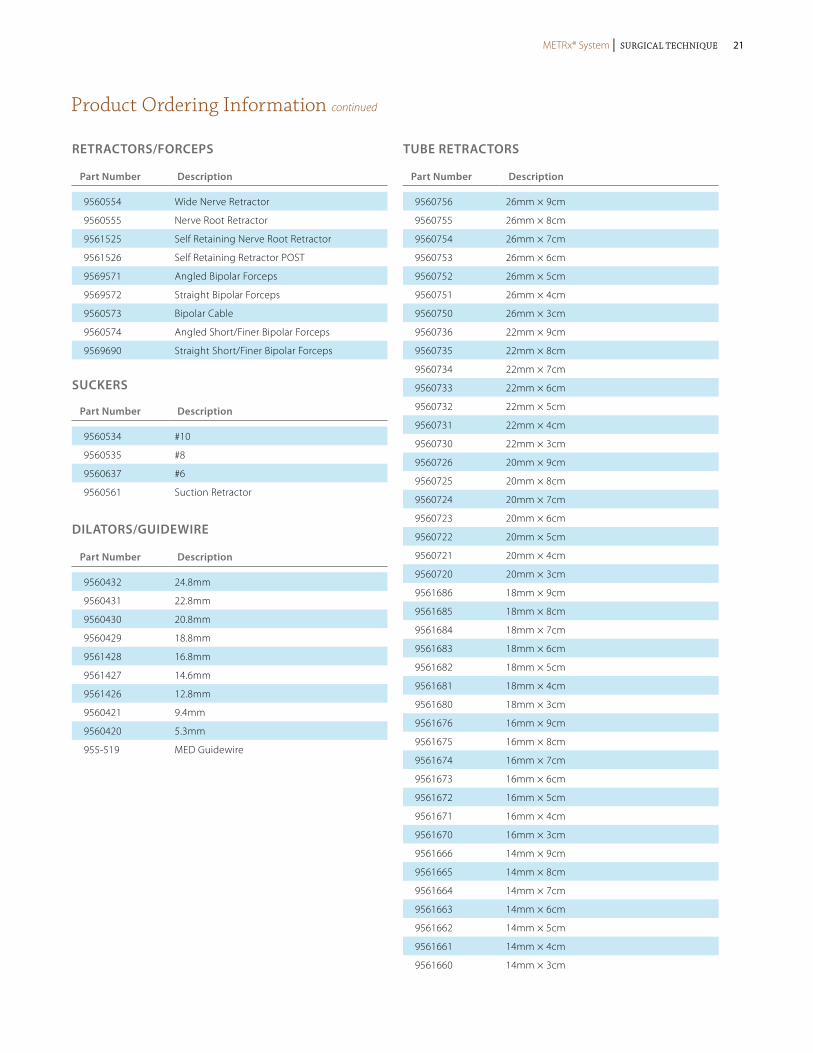
Product Ordering Information continued
Part Number Description
9560554 Wide Nerve Retractor
9560555 Nerve Root Retractor
9561525 Self Retaining Nerve Root Retractor
9561526 Self Retaining Retractor POST
9569571 Angled Bipolar Forceps
9569572 Straight Bipolar Forceps
9560573 Bipolar Cable
9560574 Angled Short/Finer Bipolar Forceps
9569690 Straight Short/Finer Bipolar Forceps
RETRACToRS/FoRCEPS
Part Number Description
9560534 #10
9560535 #8
9560637 #6
9560561 Suction Retractor
SUCKERS
Part Number Description
9560432 24.8mm
9560431 22.8mm
9560430 20.8mm
9560429 18.8mm
9561428 16.8mm
9561427 14.6mm
9561426 12.8mm
9560421 9.4mm
9560420 5.3mm
955-519 MED Guidewire
DILAToRS/GUIDEwIRE
Part Number Description
9560756 26mm × 9cm
9560755 26mm × 8cm
9560754 26mm × 7cm
9560753 26mm × 6cm
9560752 26mm × 5cm
9560751 26mm × 4cm
9560750 26mm × 3cm
9560736 22mm × 9cm
9560735 22mm × 8cm
9560734 22mm × 7cm
9560733 22mm × 6cm
9560732 22mm × 5cm
9560731 22mm × 4cm
9560730 22mm × 3cm
9560726 20mm × 9cm
9560725 20mm × 8cm
9560724 20mm × 7cm
9560723 20mm × 6cm
9560722 20mm × 5cm
9560721 20mm × 4cm
9560720 20mm × 3cm
9561686 18mm × 9cm
9561685 18mm × 8cm
9561684 18mm × 7cm
9561683 18mm × 6cm
9561682 18mm × 5cm
9561681 18mm × 4cm
9561680 18mm × 3cm
9561676 16mm × 9cm
9561675 16mm × 8cm
9561674 16mm × 7cm
9561673 16mm × 6cm
9561672 16mm × 5cm
9561671 16mm × 4cm
9561670 16mm × 3cm
9561666 14mm × 9cm
9561665 14mm × 8cm
9561664 14mm × 7cm
9561663 14mm × 6cm
9561662 14mm × 5cm
9561661 14mm × 4cm
9561660 14mm × 3cm
TUBE RETRACToRS
METRx® System | Surgical Technique METRx® System | Surgical Technique 21
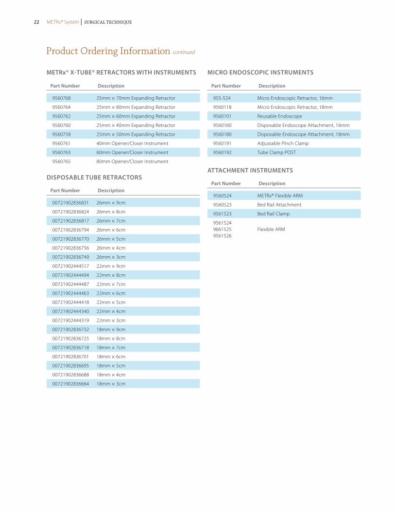
Product Ordering Information continued
Part Number Description
9560768 25mm × 70mm Expanding Retractor
9560764 25mm × 80mm Expanding Retractor
9560762 25mm × 60mm Expanding Retractor
9560760 25mm × 40mm Expanding Retractor
9560758 25mm × 50mm Expanding Retractor
9560761 40mm Opener/Closer Instrument
9560763 60mm Opener/Closer Instrument
9560765 80mm Opener/Closer Instrument
METRx® X-TUBE® RETRACToRS wITH INSTRUMENTS MICRo ENDoSCoPIC INSTRUMENTS
Part Number Description
00721902836831 26mm × 9cm
00721902836824 26mm × 8cm
00721902836817 26mm × 7cm
00721902836794 26mm × 6cm
00721902836770 26mm × 5cm
00721902836756 26mm × 4cm
00721902836749 26mm × 3cm
00721902444517 22mm × 9cm
00721902444494 22mm × 8cm
00721902444487 22mm × 7cm
00721902444463 22mm × 6cm
00721902444418 22mm × 5cm
00721902444340 22mm × 4cm
00721902444319 22mm × 3cm
00721902836732 18mm × 9cm
00721902836725 18mm × 8cm
00721902836718 18mm × 7cm
00721902836701 18mm × 6cm
00721902836695 18mm × 5cm
00721902836688 18mm × 4cm
00721902836664 18mm × 3cm
DISPoSABLE TUBE RETRACToRS
Part Number Description
955-524 Micro Endoscopic Retractor, 16mm
9560118 Micro Endoscopic Retractor, 18mm
9560101 Reusable Endoscope
9560160 Disposable Endoscope Attachment, 16mm
9560180 Disposable Endoscope Attachment, 18mm
9560191 Adjustable Pinch Clamp
9560192 Tube Clamp POST
Part Number Description
9560524 METRx® Flexible ARM
9560523 Bed Rail Attachment
9561523 Bed Rail Clamp
9561524 9661525 9561526
Flexible ARM
ATTACHMENT INSTRUMENTS
METRx® System | Surgical Technique22 METRx® System | Surgical Technique

Important Product Information
Description:The METRx™ Microscope System is composed of a microscope, camera, an integrated video system, a video monitor and recorder, and various cannula, dilators, extension lenses, and associated instruments.No warranties, express or implied are made. Implied warranties of merchantability and fitness for a particular purpose or use are specifically excluded. See the MSD Catalog for further information about warranties and limitations of liability.
A. inDicAtionsThe METRx™ Microscope is indicated for visualization of the surgical field in any area of the body cut open during a surgical proce-dure. When used in the cervical, thoracic, or lumbar spine either from an anterior or posterior direction, for example, the METRx™ Microscope and accessories are intended to aid the surgeon’s visualization of the surgical area and allow him/her to perform any type of surgical spinal procedure such as herniated disc repair, visualization of the circumferential decompression of the nerve roots, aiding in the search and removal of nucleus material, spinal fusion, or insertion of spinal implants. Other examples of generic surgi-cal use of the METRx™ Microscope would be for use in the knee, ankle, shoulder, hand, wrist, and temporomandibular joint (TMJ).
B. contrAinDicAtions The METRx™ Microscope and accessories have no known contraindications intrinsic to the device. No part of the microscope itself or its accessories should ever be used in a cutting or tearing action, i.e., never use the Microscope as an instrument. The optical device or its extension units should not be used to provide access to the surgical field. The device should not be inserted into body cavities, hollow organs, or natural body openings.There are no other known risks associated with the use of the device outside of the normal and expected risks of surgery. The microscope should not be used non-sterile or in the presence of an infectious disease process
Directions for Use:Specific instructions for use depend on patient considerations. Therefore, Medtronic Sofamor Danek cannot provide a surgical procedure that will be applicable to all situations. Any available surgical procedure brochure or manual for the METRx™ System Microscope device and accessories should be reviewed prior to use. The only critical directions for use are to insert the cannula or dilators and position them in the surgical wound prior to insertion of the microscope extension rod lens and inner field visualization of the surgical site. Never use the microscope extension to provide access or as a surgical instrument in the surgical field. Once visualization assistance is obtained, the surgeon can then complete the planned surgical procedure.
potentiAl ADverse effects:Risks possibly associated with the use of the METRx™ Microscope and accessories are similar to those associated with any surgery to the planned area of instrument use. The most frequently stated risks are bleeding, neurological damage, damage to the surrounding soft tissue, and infection. Each of these risks has also been used to describe the risks associated with conventional surgical interven-tion. Additional risks associated with the use of METRx™ Microscope, other than those described for spinal surgery in general, may be instrument malfunction, such as bending, fragmentation, loosening, and/or breakage (whole or partial). Breakage of the tip in the patient may increase surgical time, since this instrument should not be implanted. Also, the surgery may not be effective. Similar risks are associated with the system use in other parts of the body.Additional risks are attendant to surgery and the use of anesthesia, etc., and are not directly related to the use of the microscope and accessories. These include, but are not limited to, pneumonia, phlebitis, embolism, wound infection, blood loss with or without anemia.
WArnings AnD precAUtions:A successful result is not always achieved in every surgical case. This fact is especially true in orthopaedic or neuro-surgery cases where many extenuating circumstances may compromise the results.In the event of technical complications, the surgical technique can be converted to an open procedure and the surgery completed.Preoperative and operating procedures, including knowledge of surgical techniques are important considerations in the successful utilization of the system by the surgeon. Further, the proper selection of the patient and the compliance of the patient will greatly affect the results.In addition, the following should be considered:1. This device is a delicate instrument. It should NOT be dropped, bent at a sharp angle, or exposed to any type of gamma radia-
tion. Tip fracture fragmentation and optic damage may result if the microscope is not handled carefully.2. Additional microscopes and accessories should be available at the time of surgery in case of possible contamination due to
mishandling or removing the devices from the sterile field.3. Components of the system should be thoroughly inspected during cleaning prior to surgery for possible damage.4. Proper, secure component connections must be made to assure
proper functioning of the optical, irrigation, and aspiration aspects of the device.
CAUTION – High TemperatureThis light source is recommended for use with 100W light sources and 5mm fiber optic cables. Use of other cables and/or higher wattage light sources may result in high temperatures on the metal connection to the light cable which may result in injury to patient or staff and damage to product. Reduce intensity levels on high watt light sources and take precautions to protect patient and staff from injury.cAUtion: for Use on or BY tHe orDer of A pHYsiciAn onlY.
for Us AUDiences onlY
cAUtion: feDerAl lAW (UsA) restricts tHese Devices to sAle BY or on tHe orDer of A pHYsiciAn.
cleAning proceDUre:Exterior cleaning of the microscope and camera head is essential prior to any sterilization procedure. The camera head should be removed from the microscope prior to cleaning. To remove blood, organic matter, and irrigation solutions, all surfaces of the microscope and camera head should be cleaned with a mild detergent and water. Rinse with distilled, demineralized, or pyrogen-free water. Dry thoroughly. Without the removal of all contaminants from the surface, the sterilization medium will not contact the surfaces.WArning: Do not Use UltrAsonic cleAner or ABrAsives DUring tHe cleAning process.
sterilizAtion:The microscope, light cable, non-sterile instruments and instruments which are re-usable are recommended to be steam sterilized by the hospital using one of the following methods:Some cameras (9560500, 9560501) are autoclavable following the same recommendations. If the products described in this docu-ment are sterilized by the hospital in a tray or case, it must be sterilized in a tray or case provided by Medtronic Sofamor Danek.Some accessories and instruments are supplied sterile and non-reusable. Sterile product will be clearly labeled as such on the package label. The sterility of the product supplied sterile can only be assured if the packaging is intact.
NOTE: The following note applies to the process parameter identified with the * below: For use of this product and instruments outside the United States, some non-U.S. Health Care Authorities recommend sterilization according to these parameters so as to minimize the potential risk of transmission of Creutzfeldt-Jakob disease, especially of surgical instruments that could come onto contact with the central nervous system.
METHOD CYCLE TEMPERATURE EXPOSURE TIME
Steam Pre-Vacuum 270°F (132°C) 4 Minutes
Steam Gravity 250°F (121°C) 60 Minutes
Steam* Pre-Vacuum* 273°F (134°C)* 20 Minutes*
Steam* Gravity* 273°F (134°C)* 20 Minutes*
The microscope, camera and light cable can also be EtO sterilized. The following EtO cycle is recommended:
preconditioning parameters:
temperature: 55 ± 2° C
relative Humidity: ≥ 35%
vacuum: 21 ± 1 In Hg (508-559mm Hg)
preconditioning time: 1 Hour
sterilization parameters:
ethylene oxide carrier: Oxyfume 2002
temperature: 55 ± 2° C
relative Humidity: ≥ 35%
pressure: 19 ± 1 PSIG (2.25-2.39 bars)
ethylene oxide concentration: 736 mg/L
gas exposure time (full cycle): 4 Hours
Aeration: 11 Hours at 54°C minimum
The microscope and camera should be thoroughly cleaned prior to sterilization.The integrated video system, video monitor, and recorder are also reusable and supplied non-sterile. These components should not be placed in the surgical field. cAUtion: scopes AnD cAMerA cAnnot Be steAM AUtoclAveD Unless “AUtoclAvABle” is engrAveD on tHe Microscope or cAMerA BoDY. tHis MetHoD WoUlD otHerWise perMAnentlY DAMAge tHe opticAl coMponents.cAUtion: Do not iMMerse or rinse instrUMents in colD WAter or AnY otHer liQUiD to AccelerAte cooling.
proDUct coMplAints:Any Health Care Professional (e.g., customer or user of this system of products), who has any complaints or who has experienced any dissatisfaction in the product quality, identity, durability, reliability, safety, effectiveness and/or performance, should notify the distributor, Medtronic Sofamor Danek. Further, if this system ever “malfunctions,” (i.e., does not meet any of its performance speci-fications or otherwise does not perform as intended), or is suspected of doing so, the distributor should be notified immediately. If any Medtronic Sofamor Danek product ever “malfunctions” and may have caused or contributed to the death or serious injury of a patient, the distributor should be notified immediately by telephone, fax, or written correspondence. When filing a complaint, please provide the component(s) name and number, lot number(s), your name and address, the nature of the complaint, and notification of whether a written report from the distributor is requested.Further Information:If further information is needed or required, please contact:
Medtronic B.v.Earl Bakkenstraat 106422 PJ HeerlenThe NetherlandsTel: + 31 45 566 80 00
MeDtronic sofAMor DAnek UsA, inc.1800 Pyramid PlaceMemphis, TN 38132Telephone 800 933 2635 (In U.S.A.) 901 396 3133 (Outside of U.S.A.)Fax 901 396 0356
For the most up-to-date revision of the package insert, please contact Customer Service or your Sales Representative.©2009 Medtronic Sofamor Danek USA, Inc. All rights reserved.
METRx® System | Surgical Technique METRx® System | Surgical Technique 23
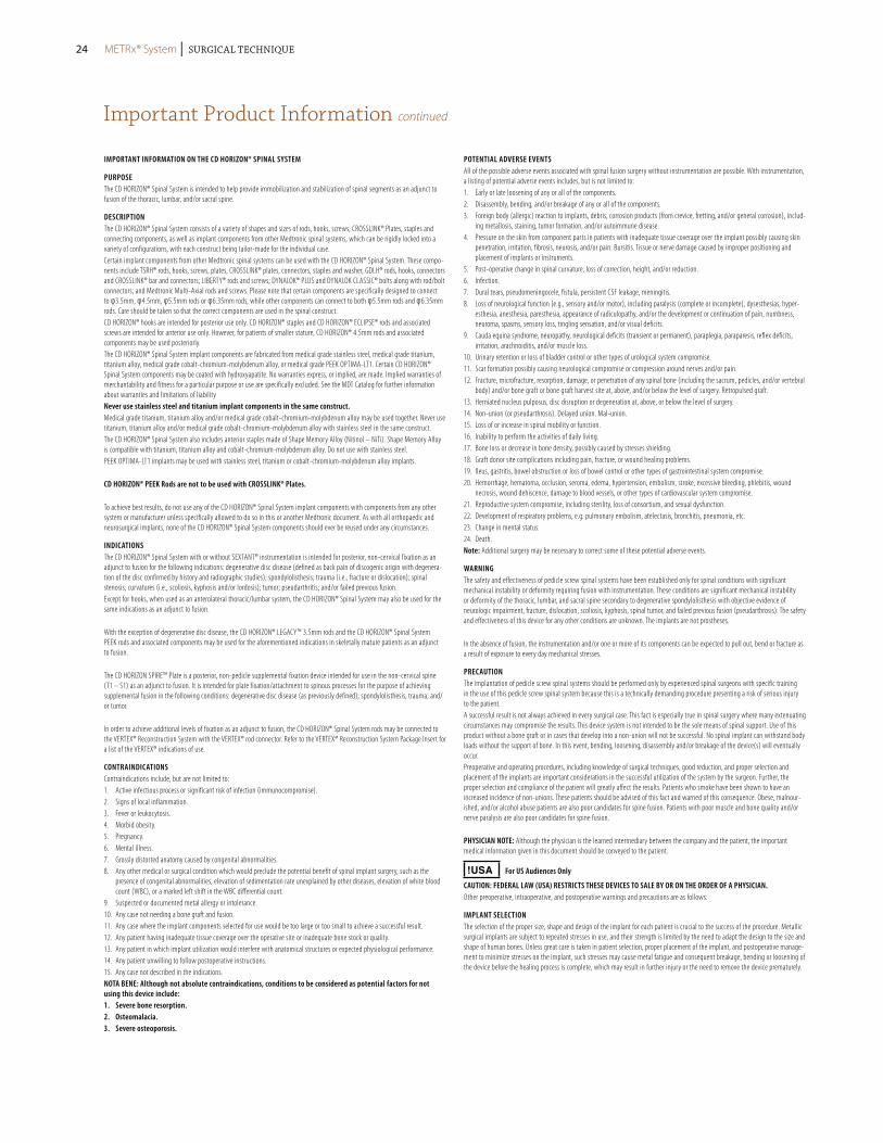
iMportAnt inforMAtion on tHe cD Horizon® spinAl sYsteM
pUrposeThe CD HORIZON® Spinal System is intended to help provide immobilization and stabilization of spinal segments as an adjunct to fusion of the thoracic, lumbar, and/or sacral spine.
DescriptionThe CD HORIZON® Spinal System consists of a variety of shapes and sizes of rods, hooks, screws, CROSSLINK® Plates, staples and connecting components, as well as implant components from other Medtronic spinal systems, which can be rigidly locked into a variety of configurations, with each construct being tailor-made for the individual case.Certain implant components from other Medtronic spinal systems can be used with the CD HORIZON® Spinal System. These compo-nents include TSRH® rods, hooks, screws, plates, CROSSLINK® plates, connectors, staples and washer, GDLH® rods, hooks, connectors and CROSSLINK® bar and connectors; LIBERTY® rods and screws; DYNALOK® PLUS and DYNALOK CLASSIC® bolts along with rod/bolt connectors; and Medtronic Multi-Axial rods and screws. Please note that certain components are specifically designed to connect to φ3.5mm, φ4.5mm, φ5.5mm rods or φ6.35mm rods, while other components can connect to both φ5.5mm rods and φ6.35mm rods. Care should be taken so that the correct components are used in the spinal construct.CD HORIZON® hooks are intended for posterior use only. CD HORIZON® staples and CD HORIZON® ECLIPSE® rods and associated screws are intended for anterior use only. However, for patients of smaller stature, CD HORIZON® 4.5mm rods and associated components may be used posteriorly.The CD HORIZON® Spinal System implant components are fabricated from medical grade stainless steel, medical grade titanium, titanium alloy, medical grade cobalt-chromium-molybdenum alloy, or medical grade PEEK OPTIMA-LT1. Certain CD HORIZON® Spinal System components may be coated with hydroxyapatite. No warranties express, or implied, are made. Implied warranties of merchantability and fitness for a particular purpose or use are specifically excluded. See the MDT Catalog for further information about warranties and limitations of liabilitynever use stainless steel and titanium implant components in the same construct. Medical grade titanium, titanium alloy and/or medical grade cobalt-chromium-molybdenum alloy may be used together. Never use titanium, titanium alloy and/or medical grade cobalt-chromium-molybdenum alloy with stainless steel in the same construct. The CD HORIZON® Spinal System also includes anterior staples made of Shape Memory Alloy (Nitinol – NiTi). Shape Memory Alloy is compatible with titanium, titanium alloy and cobalt-chromium-molybdenum alloy. Do not use with stainless steel.PEEK OPTIMA-LT1 implants may be used with stainless steel, titanium or cobalt-chromium-molybdenum alloy implants.
cD Horizon® peek rods are not to be used with crosslink® plates.
To achieve best results, do not use any of the CD HORIZON® Spinal System implant components with components from any other system or manufacturer unless specifically allowed to do so in this or another Medtronic document. As with all orthopaedic and neurosurgical implants, none of the CD HORIZON® Spinal System components should ever be reused under any circumstances.
inDicAtionsThe CD HORIZON® Spinal System with or without SEXTANT® instrumentation is intended for posterior, non-cervical fixation as an adjunct to fusion for the following indications: degenerative disc disease (defined as back pain of discogenic origin with degenera-tion of the disc confirmed by history and radiographic studies); spondylolisthesis; trauma (i.e., fracture or dislocation); spinal stenosis; curvatures (i.e., scoliosis, kyphosis and/or lordosis); tumor; pseudarthritis; and/or failed previous fusion.Except for hooks, when used as an anterolateral thoracic/lumbar system, the CD HORIZON® Spinal System may also be used for the same indications as an adjunct to fusion.
With the exception of degenerative disc disease, the CD HORIZON® LEGACY™ 3.5mm rods and the CD HORIZON® Spinal System PEEK rods and associated components may be used for the aforementioned indications in skeletally mature patients as an adjunct to fusion.
The CD HORIZON SPIRE™ Plate is a posterior, non-pedicle supplemental fixation device intended for use in the non-cervical spine (T1 – S1) as an adjunct to fusion. It is intended for plate fixation/attachment to spinous processes for the purpose of achieving supplemental fusion in the following conditions: degenerative disc disease (as previously defined); spondylolisthesis, trauma; and/or tumor.
In order to achieve additional levels of fixation as an adjunct to fusion, the CD HORIZON® Spinal System rods may be connected to the VERTEX® Reconstruction System with the VERTEX® rod connector. Refer to the VERTEX® Reconstruction System Package Insert for a list of the VERTEX® indications of use.
contrAinDicAtionsContraindications include, but are not limited to:1. Active infectious process or significant risk of infection (immunocompromise).2. Signs of local inflammation.3. Fever or leukocytosis. 4. Morbid obesity.5. Pregnancy.6. Mental illness.7. Grossly distorted anatomy caused by congenital abnormalities.8. Any other medical or surgical condition which would preclude the potential benefit of spinal implant surgery, such as the
presence of congenital abnormalities, elevation of sedimentation rate unexplained by other diseases, elevation of white blood count (WBC), or a marked left shift in the WBC differential count.
9. Suspected or documented metal allergy or intolerance.10. Any case not needing a bone graft and fusion.11. Any case where the implant components selected for use would be too large or too small to achieve a successful result. 12. Any patient having inadequate tissue coverage over the operative site or inadequate bone stock or quality.13. Any patient in which implant utilization would interfere with anatomical structures or expected physiological performance.14. Any patient unwilling to follow postoperative instructions.15. Any case not described in the indications.notA Bene: Although not absolute contraindications, conditions to be considered as potential factors for not using this device include:1. severe bone resorption.2. osteomalacia.3. severe osteoporosis.
potentiAl ADverse eventsAll of the possible adverse events associated with spinal fusion surgery without instrumentation are possible. With instrumentation, a listing of potential adverse events includes, but is not limited to:1. Early or late loosening of any or all of the components.2. Disassembly, bending, and/or breakage of any or all of the components.3. Foreign body (allergic) reaction to implants, debris, corrosion products (from crevice, fretting, and/or general corrosion), includ-
ing metallosis, staining, tumor formation, and/or autoimmune disease.4. Pressure on the skin from component parts in patients with inadequate tissue coverage over the implant possibly causing skin
penetration, irritation, fibrosis, neurosis, and/or pain. Bursitis. Tissue or nerve damage caused by improper positioning and placement of implants or instruments.
5. Post-operative change in spinal curvature, loss of correction, height, and/or reduction.6. Infection.7. Dural tears, pseudomeningocele, fistula, persistent CSF leakage, meningitis.8. Loss of neurological function (e.g., sensory and/or motor), including paralysis (complete or incomplete), dysesthesias, hyper-
esthesia, anesthesia, paresthesia, appearance of radiculopathy, and/or the development or continuation of pain, numbness, neuroma, spasms, sensory loss, tingling sensation, and/or visual deficits.
9. Cauda equina syndrome, neuropathy, neurological deficits (transient or permanent), paraplegia, paraparesis, reflex deficits, irritation, arachnoiditis, and/or muscle loss.
10. Urinary retention or loss of bladder control or other types of urological system compromise.11. Scar formation possibly causing neurological compromise or compression around nerves and/or pain.12. Fracture, microfracture, resorption, damage, or penetration of any spinal bone (including the sacrum, pedicles, and/or vertebral
body) and/or bone graft or bone graft harvest site at, above, and/or below the level of surgery. Retropulsed graft.13. Herniated nucleus pulposus, disc disruption or degeneration at, above, or below the level of surgery.14. Non-union (or pseudarthrosis). Delayed union. Mal-union.15. Loss of or increase in spinal mobility or function.16. Inability to perform the activities of daily living.17. Bone loss or decrease in bone density, possibly caused by stresses shielding.18. Graft donor site complications including pain, fracture, or wound healing problems.19. Ileus, gastritis, bowel obstruction or loss of bowel control or other types of gastrointestinal system compromise.20. Hemorrhage, hematoma, occlusion, seroma, edema, hypertension, embolism, stroke, excessive bleeding, phlebitis, wound
necrosis, wound dehiscence, damage to blood vessels, or other types of cardiovascular system compromise.21. Reproductive system compromise, including sterility, loss of consortium, and sexual dysfunction.22. Development of respiratory problems, e.g. pulmonary embolism, atelectasis, bronchitis, pneumonia, etc.23. Change in mental status.24. Death.note: Additional surgery may be necessary to correct some of these potential adverse events.
WArningThe safety and effectiveness of pedicle screw spinal systems have been established only for spinal conditions with significant mechanical instability or deformity requiring fusion with instrumentation. These conditions are significant mechanical instability or deformity of the thoracic, lumbar, and sacral spine secondary to degenerative spondylolisthesis with objective evidence of neurologic impairment, fracture, dislocation, scoliosis, kyphosis, spinal tumor, and failed previous fusion (pseudarthrosis). The safety and effectiveness of this device for any other conditions are unknown. The implants are not prostheses.
In the absence of fusion, the instrumentation and/or one or more of its components can be expected to pull out, bend or fracture as a result of exposure to every day mechanical stresses.
precAUtionThe implantation of pedicle screw spinal systems should be performed only by experienced spinal surgeons with specific training in the use of this pedicle screw spinal system because this is a technically demanding procedure presenting a risk of serious injury to the patient.A successful result is not always achieved in every surgical case. This fact is especially true in spinal surgery where many extenuating circumstances may compromise the results. This device system is not intended to be the sole means of spinal support. Use of this product without a bone graft or in cases that develop into a non-union will not be successful. No spinal implant can withstand body loads without the support of bone. In this event, bending, loosening, disassembly and/or breakage of the device(s) will eventually occur.Preoperative and operating procedures, including knowledge of surgical techniques, good reduction, and proper selection and placement of the implants are important considerations in the successful utilization of the system by the surgeon. Further, the proper selection and compliance of the patient will greatly affect the results. Patients who smoke have been shown to have an increased incidence of non-unions. These patients should be advised of this fact and warned of this consequence. Obese, malnour-ished, and/or alcohol abuse patients are also poor candidates for spine fusion. Patients with poor muscle and bone quality and/or nerve paralysis are also poor candidates for spine fusion.
pHYsiciAn note: Although the physician is the learned intermediary between the company and the patient, the important medical information given in this document should be conveyed to the patient.
!USA for Us Audiences only
cAUtion: feDerAl lAW (UsA) restricts tHese Devices to sAle BY or on tHe orDer of A pHYsiciAn.Other preoperative, intraoperative, and postoperative warnings and precautions are as follows:
iMplAnt selectionThe selection of the proper size, shape and design of the implant for each patient is crucial to the success of the procedure. Metallic surgical implants are subject to repeated stresses in use, and their strength is limited by the need to adapt the design to the size and shape of human bones. Unless great care is taken in patient selection, proper placement of the implant, and postoperative manage-ment to minimize stresses on the implant, such stresses may cause metal fatigue and consequent breakage, bending or loosening of the device before the healing process is complete, which may result in further injury or the need to remove the device prematurely.
Important Product Information continued
METRx® System | Surgical Technique24
Important Product Information continued
Device fiXAtionIn cases where a percutaneous posterior approach is used refer to the CD HORIZON® SEXTANT® surgical technique.MEDTRONIC CD HORIZON® Spinal System instrumentation contains 3.5mm, 4.5 mm, 5.5mm and/or 6.35mm rods and implants, which are intended to be used with device specific instruments.For self breaking plugs, always hold the assembly with the Counter Torque device. Tighten and break-off the head of the plug to leave the assembly at optimum fixation security. After the upper part of the self breaking plug has been sheared off, further re-tightening is not necessary and not recommended. The head part should not remain in the patient. AFTER THE UPPER PART OF THE SELF BREAKING PLUG HAS BEEN SHEARED OFF, RE-ADJUSTMENT IS NOT POSSIBLE UNLESS THE PLUG IS REMOVED AND REPLACED WITH A NEW ONE.
When using DTT Transverse Links, the M6 plug should be tightened to between 8 and 9 Nm. (70 to 80 inch-lbs).
cD Horizon® peek rods are not to be used with crosslink® plates.
preoperAtive1. Only patients that meet the criteria described in the indications should be selected.2. Patient conditions and/or pre dispositions such as those addressed in the aforementioned contraindications should be avoided.3. Care should be used in the handling and storage of the implant components. The implants should not be scratched or otherwise
damaged. Implants and instruments should be protected during storage, especially from corrosive environments.4. An adequate inventory of implants should be available at the time of surgery, normally a quantity in excess of what is expected
to be used. 5. Since mechanical parts are involved, the surgeon should be familiar with the various components before using the equipment
and should personally assemble the devices to verify that all parts and necessary instruments are present before the surgery begins. The CD HORIZON® Spinal System components (described in the DESCRIPTION section) are not to be combined with the components from another manufacturer.
6. All components and instruments should be cleaned and sterilized before use. Additional sterile components should be available in case of an unexpected need.
intrAoperAtive1. Extreme caution should be used around the spinal cord and nerve roots. Damage to the nerves will cause loss of neurological
functions.2. Breakage, slippage, or misuse of instruments or implant components may cause injury to the patient or operative personnel.3. The rods should not be repeatedly or excessively bent. The rods should not be reverse bent in the same location. Use great care
to insure that the implant surfaces are not scratched or notched, since such actions may reduce the functional strength of the construct. If the rods are cut to length, they should be cut in such a way as to create a flat, non-sharp surface perpendicular to the midline of the rod. Cut the rods outside the operative field. Whenever possible, use pre-cut rods of the length needed.
4. Utilize an imaging system to facilitate surgery.5. To insert a screw properly, a guide wire should first be used, followed by a sharp tap. Caution: Be careful that the guide-wire,
if used, is not inserted too deep, becomes bent, and/or breaks. Ensure that the guide-wire does not advance during tapping or screw insertion. Remove the guide-wire and make sure it is intact. Failure to do so may cause the guide wire or part of it to advance through the bone and into a location that may cause damage to underlying structures.
6. caution: Do not overtap or use a screw/bolt that is either too long or too large. Overtapping, using an incorrectly sized screw/bolt, or accidentally advancing the guidewire during tap or screw/bolt insertion, may cause nerve damage, hemorrhage, or the other possible adverse events listed elsewhere in this package insert. If screws/bolts are being inserted into spinal pedicles, use as large a screw/bolt diameter as will fit into each pedicle.
7. Bone graft must be placed in the area to be fused and graft material must extend from the upper to the lower vertebrae being fused.
8. To assure maximum stability, two or more CROSSLINK® plates or DTT Transverse Links on two bilaterally placed, continuous rods, should be used whenever possible.
9. Before closing the soft tissues, provisionally tighten (finger tighten) all of the nuts or screws, especially screws or nuts that have a break-off feature. Once this is completed go back and firmly tighten all of the screws and nuts. Recheck the tightness of all nuts or screws after finishing to make sure that none loosened during the tightening of the other nuts or screws. Failure to do so may cause loosening of the other components.
postoperAtiveThe physician’s postoperative directions and warnings to the patient, and the corresponding patient compliance, are extremely important.1. Detailed instructions on the use and limitations of the device should be given to the patient. If partial weight-bearing is
recommended or required prior to firm bony union, the patient must be warned that bending, loosening and/or breakage of the device(s) are complications which may occur as a result of excessive or early weight-bearing or muscular activity. The risk of bending, loosening, or breakage of a temporary internal fixation device during postoperative rehabilitation may be increased if the patient is active, or if the patient is debilitated or demented. The patient should be warned to avoid falls or sudden jolts in spinal position.
2. To allow the maximum chances for a successful surgical result, the patient or devices should not be exposed to mechanical vibrations or shock that may loosen the device construct. The patient should be warned of this possibility and instructed to limit and restrict physical activities, especially lifting and twisting motions and any type of sport participation. The patient should be advised not to smoke tobacco or utilize nicotine products, or to consume alcohol or non-steroidals or anti-inflammatory medications such as aspirin during the bone graft healing process.
3. The patient should be advised of their inability to bend or rotate at the point of spinal fusion and taught to compensate for this permanent physical restriction in body motion.
4. Failure to immobilize a delayed or non-union of bone will result in excessive and repeated stresses on the implant. By the mechanism of fatigue, these stresses can cause the eventual bending, loosening, or breakage of the device(s). It is important that immobilization of the spinal surgical site be maintained until firm bony union is established and confirmed by roentgeno-graphic examination. If a state of non-union persists or if the components loosen, bend, and/or break, the device(s) should be revised and/or removed immediately before serious injury occurs. The patient must be adequately warned of these hazards and closely supervised to insure cooperation until bony union is confirmed.
5. As a precaution, before patients with implants receive any subsequent surgery (such as dental procedures), prophylactic antibiotics may be considered, especially for high-risk patients.
6. The CD HORIZON® Spinal System implants are temporary internal fixation devices. Internal fixation devices are designed to stabilize the operative site during the normal healing process. After the spine is fused, these devices serve no functional purpose and may be removed. While the final decision on implant removal is, of course, up to the surgeon and patient, in most patients, removal is indicated because the implants are not intended to transfer or support forces developed during normal activities. If the device is not removed following completion of its intended use, one or more of the following complications may occur: (1) Corrosion, with localized tissue reaction or pain; (2) Migration of implant position, possibly resulting in injury; (3) Risk of
additional injury from postoperative trauma; (4) Bending, loosening and breakage, which could make removal impractical or difficult; (5) Pain, discomfort, or abnormal sensations due to the presence of the device; (6) Possible increased risk of infection; (7) Bone loss due to stress shielding; and (8) Potential unknown and/or unexpected long term effects such as carcinogenesis. Implant removal should be followed by adequate postoperative management to avoid fracture, re-fracture, or other complica-tions.
7. Any retrieved devices should be treated in such a manner that reuse in another surgical procedure is not possible. As with all orthopedic implants, the CD HORIZON® Spinal System components should never be reused under any circumstances.
pAckAgingPackages for each of the components should be intact upon receipt. If a loaner or consignment system is used, all sets should be carefully checked for completeness and all components including instruments should be carefully checked to ensure that there is no damage prior to use. Damaged packages or products should not be used, and should be returned to Medtronic.
cleAning AnD DecontAMinAtionUnless just removed from an unopened Medtronic package, all instruments and implants must be disassembled (if applicable) and cleaned using neutral cleaners before sterilization and introduction into a sterile surgical field or (if applicable) return of the product to Medtronic. Cleaning and disinfecting of instruments can be performed with aldehyde-free solvents at higher temperatures. Cleaning and decontamination must include the use of neutral cleaners followed by a deionized water rinse.Note: certain cleaning solutions such as those containing formalin, glutaraldehyde, bleach and/or other alkaline cleaners may damage some devices, particularly instruments; these solutions should not be used. Also, many instruments require disassembly before cleaning.All products should be treated with care. Improper use or handling may lead to damage and/or possible improper functioning of the device.
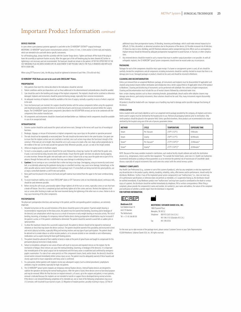
sterilizAtionUnless marked sterile and clearly labeled as such in an unopened sterile package provided by the company, all implants and instru-ments used in surgery must be sterilized by the hospital prior to use. Remove all packaging materials prior to sterilization. Only sterile products should be placed in the operative field. Unless specified elsewhere, these products are recommended to be steam sterilized by the hospital using one of the sets of process parameters below:
MetHoD cYcle teMperAtUre eXposUre tiMe
Steam Pre-Vacuum 270°F (132°C) 4 Minutes
Steam Gravity 250°F (121°C) 60 Minutes
Steam* Pre-Vacuum* 273°F (134°C)* 20 Minutes*
Steam* Gravity* 273°F (134°C)* 20 Minutes*
NOTE: Because of the many variables involved in sterilization, each medical facility should calibrate and verify the sterilization process (e.g., temperatures, times) used for their equipment. *For outside the United States, some non-U.S. Health Care Authorities recommend sterilization according to these parameters so as to minimize the potential risk of transmission of Creutzfeldt-Jakob disease, especially of surgical instruments that could come into contact with the central nervous system.
proDUct coMplAintsAny Health Care Professional (e.g., customer or user of this system of products), who has any complaints or who has experienced any dissatisfaction in the product quality, identity, durability, reliability, safety, effectiveness and/or performance, should notify the distributor, Medtronic. Further, if any of the implanted spinal system component(s) ever “malfunctions,” (i.e., does not meet any of its performance specifications or otherwise does not perform as intended), or is suspected of doing so, the distributor should be notified immediately. If any Medtronic product ever “malfunctions” and may have caused or contributed to the death or serious injury of a patient, the distributor should be notified immediately by telephone, FAX or written correspondence. When filing a complaint, please provide the component(s) name and number, lot number(s), your name and address, the nature of the complaint and notification of whether a written report from the distributor is requested.for fUrtHer inforMAtion:
Medtronic B.v.Earl Bakkenstraat 106422 PJ HeerlenThe NetherlandsTel: + 31 45 566 80 00
MeDtronic sofAMor DAnek UsA, inc.1800 Pyramid PlaceMemphis, TN 38132Telephone 800 933 2635 (In U.S.A.) 901 396 3133 (Outside of U.S.A.)Fax 901 396 0356
For the most up-to-date revision of the package insert, please contact Customer Service or your Sales Representative.©2009 Medtronic Sofamor Danek USA, Inc. All rights reserved.
METRx® System | Surgical Technique 25

Notes
METRx® System | Surgical TechniqueMETRx® System | Surgical Technique26

Notes
METRx® System | Surgical Technique 2727

Notes
METRx® System | Surgical Technique28

METRx® System | Surgical Technique

MLITMTXST8IRNXXXX/XXX ©2008 Medtronic Sofamor Danek USA, Inc.All Rights Reserved.
Medtronic Spinal and Biologics Business Worldwide Headquarters
2600 Sofamor Danek DriveMemphis, TN 38132
1800 Pyramid PlaceMemphis, TN 38132
(901) 396-3133(800) 876-3133Customer Service: (800) 933-2635
For more information visit www.myspinetools.com
www.sofamordanek.com
MLI
TMET
RXST
9 ©
2009
Med
tron
ic S
ofam
or D
anek
USA
, Inc
. All
Righ
ts R
eser
ved.
IRN
8968
-1.1
-03/
079
The surgical technique shown is for illustrative purposes only. The technique(s) actually employed in each case will always depend upon the medical judgment of the surgeon exercised before and during surgery as to the best mode of treatment for each patient.
Please see the package insert for the complete list of indications, warnings, precautions, and other important medical information.