system time stamping - user guide - 04/2015 · vijeo citect user guide supplied with vijeo citect...
TRANSCRIPT
System Time Stamping
EIO0000001217 04/2015
EIO
0000
0012
17.0
1
www.schneider-electric.com
System Time StampingUser Guide
04/2015

The information provided in this documentation contains general descriptions and/or technical characteristics of the performance of the products contained herein. This documentation is not intended as a substitute for and is not to be used for determining suitability or reliability of these products for specific user applications. It is the duty of any such user or integrator to perform the appropriate and complete risk analysis, evaluation and testing of the products with respect to the relevant specific application or use thereof. Neither Schneider Electric nor any of its affiliates or subsidiaries shall be responsible or liable for misuse of the information contained herein. If you have any suggestions for improvements or amendments or have found errors in this publication, please notify us.
No part of this document may be reproduced in any form or by any means, electronic or mechanical, including photocopying, without express written permission of Schneider Electric.
All pertinent state, regional, and local safety regulations must be observed when installing and using this product. For reasons of safety and to help ensure compliance with documented system data, only the manufacturer should perform repairs to components.
When devices are used for applications with technical safety requirements, the relevant instructions must be followed.
Failure to use Schneider Electric software or approved software with our hardware products may result in injury, harm, or improper operating results.
Failure to observe this information can result in injury or equipment damage.
© 2015 Schneider Electric. All rights reserved.
2 EIO0000001217 04/2015
Table of Contents
Safety Information . . . . . . . . . . . . . . . . . . . . . . . . . . . . . 7About the Book. . . . . . . . . . . . . . . . . . . . . . . . . . . . . . . . 11
Part I Introduction to System Time Stamping . . . . . . . . 15Chapter 1 Presentation . . . . . . . . . . . . . . . . . . . . . . . . . . . . . . . . . . 17
Concepts . . . . . . . . . . . . . . . . . . . . . . . . . . . . . . . . . . . . . . . . . . . . . . . 18System Time Stamping Solution . . . . . . . . . . . . . . . . . . . . . . . . . . . . . 19System Time Stamping Limitations . . . . . . . . . . . . . . . . . . . . . . . . . . . 22
Part II System Time Stamping Architecture . . . . . . . . . . 23Chapter 2 Components . . . . . . . . . . . . . . . . . . . . . . . . . . . . . . . . . . 25
Vijeo Citect . . . . . . . . . . . . . . . . . . . . . . . . . . . . . . . . . . . . . . . . . . . . . 263rd Party Client SCADA . . . . . . . . . . . . . . . . . . . . . . . . . . . . . . . . . . . 27Time Synchronization . . . . . . . . . . . . . . . . . . . . . . . . . . . . . . . . . . . . . 28OFS . . . . . . . . . . . . . . . . . . . . . . . . . . . . . . . . . . . . . . . . . . . . . . . . . . . 29Unity Pro . . . . . . . . . . . . . . . . . . . . . . . . . . . . . . . . . . . . . . . . . . . . . . . 30BME P58 xxxx CPU. . . . . . . . . . . . . . . . . . . . . . . . . . . . . . . . . . . . . . . 31BMX ERT 1604 T Module . . . . . . . . . . . . . . . . . . . . . . . . . . . . . . . . . . 32BMx CRA 312 10 Module . . . . . . . . . . . . . . . . . . . . . . . . . . . . . . . . . . 33Router . . . . . . . . . . . . . . . . . . . . . . . . . . . . . . . . . . . . . . . . . . . . . . . . . 35Modicon M340 Ethernet Communication Modules in a Local Drop. . . 36
Chapter 3 Components Versions . . . . . . . . . . . . . . . . . . . . . . . . . . 37Components Version . . . . . . . . . . . . . . . . . . . . . . . . . . . . . . . . . . . . . . 37
Chapter 4 Architecture Examples. . . . . . . . . . . . . . . . . . . . . . . . . . 39Time Stamping Typical Architecture . . . . . . . . . . . . . . . . . . . . . . . . . . 40Modicon M580 Typical Architecture . . . . . . . . . . . . . . . . . . . . . . . . . . 42Modicon M340 Typical Architecture . . . . . . . . . . . . . . . . . . . . . . . . . . 46Modicon Quantum Typical Architecture. . . . . . . . . . . . . . . . . . . . . . . . 47Redundant Architectures . . . . . . . . . . . . . . . . . . . . . . . . . . . . . . . . . . . 50
Chapter 5 Performances . . . . . . . . . . . . . . . . . . . . . . . . . . . . . . . . . 53Performances . . . . . . . . . . . . . . . . . . . . . . . . . . . . . . . . . . . . . . . . . . . 53
Part III Design and Configuration Phases . . . . . . . . . . . . 57Chapter 6 Selecting the Time Stamping Module. . . . . . . . . . . . . . 59
Time Resolution. . . . . . . . . . . . . . . . . . . . . . . . . . . . . . . . . . . . . . . . . . 59
EIO0000001217 04/2015 3
Chapter 7 Selecting and Setting Time Synchronization . . . . . . . 61Selecting the Time Source . . . . . . . . . . . . . . . . . . . . . . . . . . . . . . . . . . 62Unity Pro Project Setting . . . . . . . . . . . . . . . . . . . . . . . . . . . . . . . . . . . 65BME P58 xxxx Clock Settings in Unity Pro . . . . . . . . . . . . . . . . . . . . . 66BMX ERT 1604 T Clock Settings in Unity Pro . . . . . . . . . . . . . . . . . . . 68BMx CRA 312 10 Clock Settings in Unity Pro . . . . . . . . . . . . . . . . . . . 69
Chapter 8 Activating System Time Stamping Service . . . . . . . . . 71Unity Pro Settings . . . . . . . . . . . . . . . . . . . . . . . . . . . . . . . . . . . . . . . . 72OFS Settings . . . . . . . . . . . . . . . . . . . . . . . . . . . . . . . . . . . . . . . . . . . . 76
Chapter 9 Selecting and Configuring the Variables to Time Stamp . . . . . . . . . . . . . . . . . . . . . . . . . . . . . . . . . . . . . . . 79Variables Usage. . . . . . . . . . . . . . . . . . . . . . . . . . . . . . . . . . . . . . . . . . 80BME P58 xxxx Variables Settings in Unity Pro . . . . . . . . . . . . . . . . . . 81BMX ERT 1604 T Variables Settings in Unity Pro . . . . . . . . . . . . . . . . 82BMx CRA 312 10 Variables Settings in Unity Pro . . . . . . . . . . . . . . . . 89
Chapter 10 Selecting the Communication Parameters . . . . . . . . . 91Capability Checks . . . . . . . . . . . . . . . . . . . . . . . . . . . . . . . . . . . . . . . . 92OFS Communication Settings . . . . . . . . . . . . . . . . . . . . . . . . . . . . . . . 94
Chapter 11 Setting Vijeo Citect Parameters . . . . . . . . . . . . . . . . . . 95Vijeo Citect Parameters . . . . . . . . . . . . . . . . . . . . . . . . . . . . . . . . . . . . 96Time Quality and SOE Uncertain Sequence . . . . . . . . . . . . . . . . . . . . 100
Part IV Commissioning and Operation Phases . . . . . . . . 103Chapter 12 Diagnostic. . . . . . . . . . . . . . . . . . . . . . . . . . . . . . . . . . . . 105
Introduction . . . . . . . . . . . . . . . . . . . . . . . . . . . . . . . . . . . . . . . . . . . . . 106PLC View . . . . . . . . . . . . . . . . . . . . . . . . . . . . . . . . . . . . . . . . . . . . . . . 107OFS View . . . . . . . . . . . . . . . . . . . . . . . . . . . . . . . . . . . . . . . . . . . . . . . 109Vijeo Citect View . . . . . . . . . . . . . . . . . . . . . . . . . . . . . . . . . . . . . . . . . 111Hardware Diagnostic . . . . . . . . . . . . . . . . . . . . . . . . . . . . . . . . . . . . . . 114
Chapter 13 Behavior on Operating Modes . . . . . . . . . . . . . . . . . . . 119Operating Modes . . . . . . . . . . . . . . . . . . . . . . . . . . . . . . . . . . . . . . . . . 120Initial Start After the Application Download and First Start with Connection of the SCADA Server . . . . . . . . . . . . . . . . . . . . . . . . . . . . 121Power Down/Up of a Time Stamping Module . . . . . . . . . . . . . . . . . . . 123Module Internal Event Buffer Full. . . . . . . . . . . . . . . . . . . . . . . . . . . . . 125Restart of the SCADA Server. . . . . . . . . . . . . . . . . . . . . . . . . . . . . . . . 127Specific Operating Modes . . . . . . . . . . . . . . . . . . . . . . . . . . . . . . . . . . 129
Chapter 14 Behavior on Time Synchronization . . . . . . . . . . . . . . . 133Time Synchronization. . . . . . . . . . . . . . . . . . . . . . . . . . . . . . . . . . . . . . 133
4 EIO0000001217 04/2015
Part V How to Interface with a 3rd Party Client SCADA . 137Chapter 15 3rd Party Client SCADA . . . . . . . . . . . . . . . . . . . . . . . . . 139
OPC Events Group . . . . . . . . . . . . . . . . . . . . . . . . . . . . . . . . . . . . . . . 140Operation Steps. . . . . . . . . . . . . . . . . . . . . . . . . . . . . . . . . . . . . . . . . . 141Optional Functionalities . . . . . . . . . . . . . . . . . . . . . . . . . . . . . . . . . . . . 142##TSEventsGroup## OnDataChange Interface . . . . . . . . . . . . . . 143
Part VI Troubleshooting . . . . . . . . . . . . . . . . . . . . . . . . . . . 145Chapter 16 Troubleshooting SOE Page in Vijeo Citect V7.30 . . . . 147
Vijeo Citect SOE Display Troubleshooting . . . . . . . . . . . . . . . . . . . . . 147Appendices . . . . . . . . . . . . . . . . . . . . . . . . . . . . . . . . . . . . . . . . . 151
Appendix A Event Format. . . . . . . . . . . . . . . . . . . . . . . . . . . . . . . . . . 153Event Time Stamp Entry . . . . . . . . . . . . . . . . . . . . . . . . . . . . . . . . . . . 153
Glossary . . . . . . . . . . . . . . . . . . . . . . . . . . . . . . . . . . . . . . . . . 157Index . . . . . . . . . . . . . . . . . . . . . . . . . . . . . . . . . . . . . . . . . 159
EIO0000001217 04/2015 5

6 EIO0000001217 04/2015
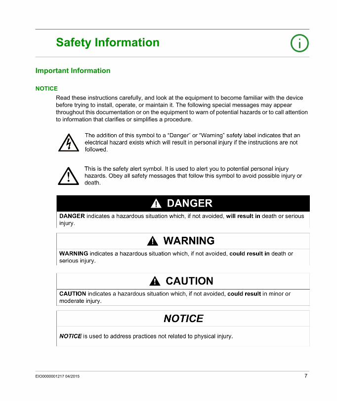
Safety Information
Important Information
NOTICE
Read these instructions carefully, and look at the equipment to become familiar with the device before trying to install, operate, or maintain it. The following special messages may appear throughout this documentation or on the equipment to warn of potential hazards or to call attention to information that clarifies or simplifies a procedure.
EIO0000001217 04/2015 7
PLEASE NOTE
Electrical equipment should be installed, operated, serviced, and maintained only by qualified personnel. No responsibility is assumed by Schneider Electric for any consequences arising out of the use of this material.
A qualified person is one who has skills and knowledge related to the construction and operation of electrical equipment and its installation, and has received safety training to recognize and avoid the hazards involved.
BEFORE YOU BEGIN
Do not use this product on machinery lacking effective point-of-operation guarding. Lack of effective point-of-operation guarding on a machine can result in serious injury to the operator of that machine.
This automation equipment and related software is used to control a variety of industrial processes. The type or model of automation equipment suitable for each application will vary depending on factors such as the control function required, degree of protection required, production methods, unusual conditions, government regulations, etc. In some applications, more than one processor may be required, as when backup redundancy is needed.
Only you, the user, machine builder or system integrator can be aware of all the conditions and factors present during setup, operation, and maintenance of the machine and, therefore, can determine the automation equipment and the related safeties and interlocks which can be properly used. When selecting automation and control equipment and related software for a particular application, you should refer to the applicable local and national standards and regulations. The National Safety Council’s Accident Prevention Manual (nationally recognized in the United States of America) also provides much useful information.
In some applications, such as packaging machinery, additional operator protection such as point-of-operation guarding must be provided. This is necessary if the operator’s hands and other parts of the body are free to enter the pinch points or other hazardous areas and serious injury can occur. Software products alone cannot protect an operator from injury. For this reason the software cannot be substituted for or take the place of point-of-operation protection.
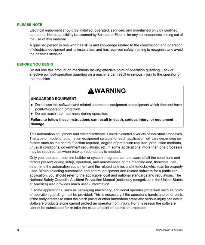
WARNINGUNGUARDED EQUIPMENT
Do not use this software and related automation equipment on equipment which does not have point-of-operation protection.
Do not reach into machinery during operation.
Failure to follow these instructions can result in death, serious injury, or equipment damage.
8 EIO0000001217 04/2015
Ensure that appropriate safeties and mechanical/electrical interlocks related to point-of-operation protection have been installed and are operational before placing the equipment into service. All interlocks and safeties related to point-of-operation protection must be coordinated with the related automation equipment and software programming.
NOTE: Coordination of safeties and mechanical/electrical interlocks for point-of-operation protection is outside the scope of the Function Block Library, System User Guide, or other implementation referenced in this documentation.
START-UP AND TEST
Before using electrical control and automation equipment for regular operation after installation, the system should be given a start-up test by qualified personnel to verify correct operation of the equipment. It is important that arrangements for such a check be made and that enough time is allowed to perform complete and satisfactory testing.
Follow all start-up tests recommended in the equipment documentation. Store all equipment documentation for future references.
Software testing must be done in both simulated and real environments.
Verify that the completed system is free from all short circuits and temporary grounds that are not installed according to local regulations (according to the National Electrical Code in the U.S.A, for instance). If high-potential voltage testing is necessary, follow recommendations in equipment documentation to prevent accidental equipment damage.
Before energizing equipment: Remove tools, meters, and debris from equipment. Close the equipment enclosure door. Remove all temporary grounds from incoming power lines. Perform all start-up tests recommended by the manufacturer.
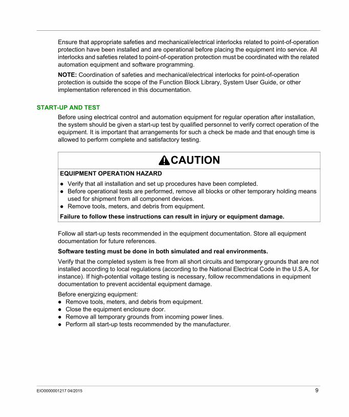
CAUTIONEQUIPMENT OPERATION HAZARD
Verify that all installation and set up procedures have been completed. Before operational tests are performed, remove all blocks or other temporary holding means
used for shipment from all component devices. Remove tools, meters, and debris from equipment.
Failure to follow these instructions can result in injury or equipment damage.
EIO0000001217 04/2015 9
OPERATION AND ADJUSTMENTS
The following precautions are from the NEMA Standards Publication ICS 7.1-1995 (English version prevails): Regardless of the care exercised in the design and manufacture of equipment or in the selection
and ratings of components, there are hazards that can be encountered if such equipment is improperly operated.
It is sometimes possible to misadjust the equipment and thus produce unsatisfactory or unsafe operation. Always use the manufacturer’s instructions as a guide for functional adjustments. Personnel who have access to these adjustments should be familiar with the equipment manufacturer’s instructions and the machinery used with the electrical equipment.
Only those operational adjustments actually required by the operator should be accessible to the operator. Access to other controls should be restricted to prevent unauthorized changes in operating characteristics.
10 EIO0000001217 04/2015
About the Book
At a Glance
Document Scope
This document presents a PlantStruxure feature: at source system time stamping.
This guide presents detailed information about system time stamping, including the following: System time stamping architecture Design and configuration phases Commissioning and operation phases Interface with a 3rd party client SCADA interface
Validity Note
This document is valid from OFS V3.40, Vijeo Citect V7.30, and Unity Pro 10.0.
The technical characteristics of the devices described in this document also appear online. To access this information online:
The characteristics that are presented in this manual should be the same as those characteristics that appear online. In line with our policy of constant improvement, we may revise content over time to improve clarity and accuracy. If you see a difference between the manual and online information, use the online information as your reference.
Step Action
1 Go to the Schneider Electric home page www.schneider-electric.com.
2 In the Search box type the reference of a product or the name of a product range. Do not include blank spaces in the reference or product range. To get information on grouping similar modules, use asterisks (*).
3 If you entered a reference, go to the Product Datasheets search results and click on the reference that interests you.If you entered the name of a product range, go to the Product Ranges search results and click on the product range that interests you.
4 If more than one reference appears in the Products search results, click on the reference that interests you.
5 Depending on the size of your screen, you may need to scroll down to see the data sheet.
6 To save or print a data sheet as a .pdf file, click Download XXX product datasheet.
EIO0000001217 04/2015 11
Related Documents
Title of Documentation Reference Number
OPC Factory Server V3.50, User Manual 35008244 (Eng), 35008244 (Fre), 35008244 (Ger)
Vijeo Citect User Guide Supplied with Vijeo Citect installation files and installed with Vijeo Citect.
Vijeo Citect Help Installed with Vijeo Citect.
BMX ERT 1604 T, M340 ERT Module, User Manual EIO0000001121 (Eng), EIO0000001122 (Fre), EIO0000001123 (Ger), EIO0000001125 (Ita), EIO0000001124 (Spa), EIO0000001126 (Chs)
Quantum EIO, System Planning Guide S1A48959 (Eng), S1A48961 (Fre), S1A48962 (Ger), S1A48964 (Ita), S1A48965 (Spa), S1A48966 (Chs)
Quantum EIO, Remote I/O Modules, Installation and Configuration Guide
S1A48978 (Eng), S1A48981 (Fre), S1A48982 (Ger), S1A48983 (Ita), S1A48984 (Spa), S1A48985 (Chs)
Quantum EIO, Control Network, Installation and Configuration Guide S1A48993 (Eng), S1A48994 (Fre), S1A48995 (Ger), S1A48997 (Ita), S1A48998 (Spa), S1A48999 (Chs)
Modicon Quantum, Hot Standby System, User Manual 35010533 (Eng), 35010534 (Fre), 35010535 (Ger), 35013993 (Ita), 35010536 (Spa), 35012188 (Chs)
12 EIO0000001217 04/2015
Modicon Quantum, Change Configuration On The Fly, User Guide S1A48967 (Eng), S1A48968 (Fre), S1A48969 (Ger), S1A48970 (Ita), S1A48972 (Spa), S1A48976 (Chs)
Applicative Time Stamping with Unity Pro, User Guide EIO0000001268 (Eng), EIO0000001702 (Fre), EIO0000001703 (Ger), EIO0000001705 (Ita), EIO0000001704 (Spa), EIO0000001706 (Chs)
Modicon M340 for Ethernet, Communications Modules and Processors, User Manual
31007131 (Eng), 31007132 (Fre), 31007133 (Ger), 31007494 (Ita), 31007134 (Spa), 31007493 (Chs)
Modicon M340, BMX NOC 0401 Ethernet Communication Module, User Manual
S1A34009 (Eng), S1A34010 (Fre), S1A34011 (Ger), S1A34013 (Ita), S1A34012 (Spa), S1A34014 (Chs)
Modicon M580 System Planning Guide HRB62666 (English), HRB65318 (French), HRB65319 (German), HRB65320 (Italian), HRB65321 (Spanish), HRB65322 (Chinese)
Modicon M580 Hardware Reference Manual EIO0000001578 (English), EIO0000001579 (French), EIO0000001580 (German), EIO0000001582 (Italian), EIO0000001581 (Spanish), EIO0000001583 (Chinese)
Unity Pro System Bits and Words, Reference Manual EIO0000002135 (English), EIO0000002136 (French), EIO0000002317 (German), EIO0000002138 (Italian), EIO0000002139 (Spanish), EIO0000002140 (Chinese)
Title of Documentation Reference Number
EIO0000001217 04/2015 13
You can download these technical publications and other technical information from our website at www.schneider-electric.com.
Unity Pro Operating Modes 33003101 (English), 33003102 (French),33003103 (German), 33003696 (Italian),33003104 (Spanish),33003697 (Chinese)
Title of Documentation Reference Number
14 EIO0000001217 04/2015
System Time Stamping
Introduction
EIO0000001217 04/2015
Introduction to System Time Stamping
Part IIntroduction to System Time Stamping
EIO0000001217 04/2015 15

Introduction
16 EIO0000001217 04/2015
System Time Stamping
Presentation
EIO0000001217 04/2015
Presentation
Chapter 1Presentation
What Is in This Chapter?
This chapter contains the following topics:
Topic Page
Concepts 18
System Time Stamping Solution 19
System Time Stamping Limitations 22
EIO0000001217 04/2015 17
Presentation
Concepts
Definition
The system time stamping provides a consistent SOE (sequence of events), time stamped at the source, in order to allow the user to analyze the source of abnormal behavior in a distributed automation system.
The SOE is displayed in an alarm summary or SOE page of a client (such as a SCADA).
Each source of time stamped event of the SOE is a discrete I/O value change (transition) detected by a time stamping module or an internal variable value change detected by a PLC.
The following graphic shows an example of Vijeo Citect SOE page display:
Benefits
The system time stamping benefits are: No need for PLC programming. Direct communication between the time stamping modules and the client. If the time stamping
modules are in a Modicon Quantum or M580 Ethernet I/O drop, the PLC communication bandwidth is not used.
Consistency in the I/O values between the process (time stamping modules) and the client (SCADA).
Advanced diagnostic functions: Signalization of uncertain SOE (sequence during which some events may be lost) to the
client. Time quality information associated with each time stamped event.
No loss of events in normal operating conditions: A buffer is available to store the events in each time stamping module. The event storage is
stopped when the buffer is full. Rising and falling edges transitions are stored for each discrete I/O and PLC internal
variables.
Hot Standby configurations on the PLC and/or redundant SCADA are managed.
18 EIO0000001217 04/2015
Presentation
System Time Stamping Solution
System Time Stamping Versus Applicative Time Stamping
System time stamping: All in one solution to benefit from at source time stamping, easy to start up without requiring any user programming. This solution requires the OFS product in the architecture.
Applicative time stamping: Solution recommended when a 3rd party SCADA that does not support OPC DA interface is required. In this case, events are read by function blocks in the PLC application (with Unity Pro software) and the events read are formatted to be sent to the SCADA. For more details on the applicative mode, refer to the Applicative Time Stamping with Unity Pro, User Guide (see page 12).
NOTE: System and applicative time stamping modes are exclusive in the same Unity Pro application running in the PLC.
NOTE: Only the system time stamping mode allows Modicon M580 CPU internal variable time stamping.
NOTE: Time stamping with 140 ERT 854 •0 modules can be used in both applicative and system modes, but this topic is not discussed in this guide. For more details on those modules, refer to the Quantum with Unity Pro, 140 ERT 854 10 Time Stamp Module, User’s Guide and the Quantum with Unity Pro, 140 ERT 854 20 Time Stamp Module, User’s Guide.
EIO0000001217 04/2015 19
Presentation
Examples of System Time Stamping Architectures
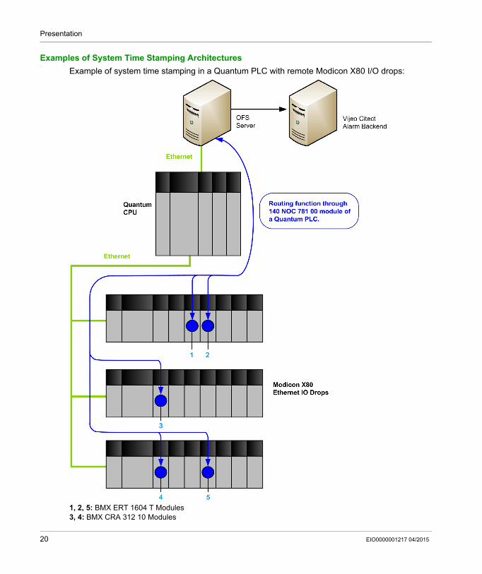
Example of system time stamping in a Quantum PLC with remote Modicon X80 I/O drops:
1, 2, 5: BMX ERT 1604 T Modules3, 4: BMX CRA 312 10 Modules
20 EIO0000001217 04/2015
Presentation
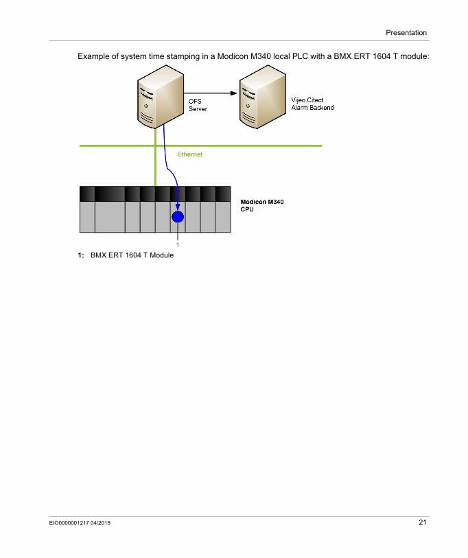
Example of system time stamping in a Modicon M340 local PLC with a BMX ERT 1604 T module:
1: BMX ERT 1604 T Module
EIO0000001217 04/2015 21
Presentation
System Time Stamping Limitations
System Limitations
At source time stamped events online change service is not available. A maximum of 1000 internal variables are managed per Modicon M580 CPU. No selection of transition edges: Events detection is processed on both value change edges
(rising and falling). A Modicon X80 Ethernet RIO drop supports up to 36 expert channels. A BMX ERT 1604 T
module is counted as 4 expert channels. In a Modicon M340 local drop, the maximum number of BMX ERT 1604 T modules depends on
the local drop CPU type. For more details, refer to BMX ERT 1604 T, M340 ERT Module, User Manual (see page 12).
A maximum of 256 discrete I/Os are managed per BM• CRA 312 10 module. A maximum of 2500 discrete I/Os per Quantum PLC are managed. A maximum of 144 discrete inputs per Modicon M340 PLC (local drop) are managed. 128
discrete inputs can be managed by BMX P34 2000/2010/2020 processors. System time stamping solution does not support the CCOTF function.
System Constraints
2 OPC servers, running on HMI and SCADA for example, cannot access simultaneously the same time stamping source. A reservation mechanism is implemented to avoid simultaneous access.
A communication path between OFS and the time stamping sources is mandatory to manage at source time stamping solution. If routers are placed in the communication path, they have to be set accordingly.
Compatibility
Redundancy in a Quantum PLC local drop (Hot Standby configuration) is compatible with system time stamping. For more details, refer to Modicon Quantum Hot Standby System User Manual (see page 12).
SCADA redundancy is compatible with system time stamping.
22 EIO0000001217 04/2015
System Time Stamping
Architecture
EIO0000001217 04/2015
System Time Stamping Architecture
Part IISystem Time Stamping Architecture
Introduction
This part presents the list of system time stamping components, component versions, performances, and architecture examples.
What Is in This Part?
This part contains the following chapters:
Chapter Chapter Name Page
2 Components 25
3 Components Versions 37
4 Architecture Examples 39
5 Performances 53
EIO0000001217 04/2015 23

Architecture
24 EIO0000001217 04/2015
System Time Stamping
Components
EIO0000001217 04/2015
Components
Chapter 2Components
Overview
This chapter presents the components involved in a system time stamping solution.
What Is in This Chapter?
This chapter contains the following topics:
Topic Page
Vijeo Citect 26
3rd Party Client SCADA 27
Time Synchronization 28
OFS 29
Unity Pro 30
BME P58 xxxx CPU 31
BMX ERT 1604 T Module 32
BMx CRA 312 10 Module 33
Router 35
Modicon M340 Ethernet Communication Modules in a Local Drop 36
EIO0000001217 04/2015 25
Components
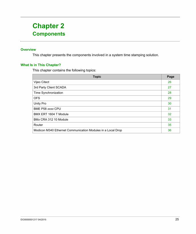
Vijeo Citect
Vijeo Citect in the System
Vijeo Citect Role
Vijeo Citect is the final client in a time stamping architecture. Vijeo Citect displays the sequence of events in an alarm viewer history or in an event viewer. It is the operating and monitoring
component of Schneider Electric PlantStruxureTM.
Vijeo Citect, with its powerful display capabilities and its operational features, delivers actionable insight faster, enabling operators to respond quickly to process disturbances, thereby increasing their efficiency.
Vijeo Citect offers the functions of a modern supervisor. Its distributed client-server architecture is applicable to a multitude of applications.
Vijeo Citect offers true redundancy for all the system components. Redundancy functions are fully integrated in the system.
26 EIO0000001217 04/2015
Components
3rd Party Client SCADA
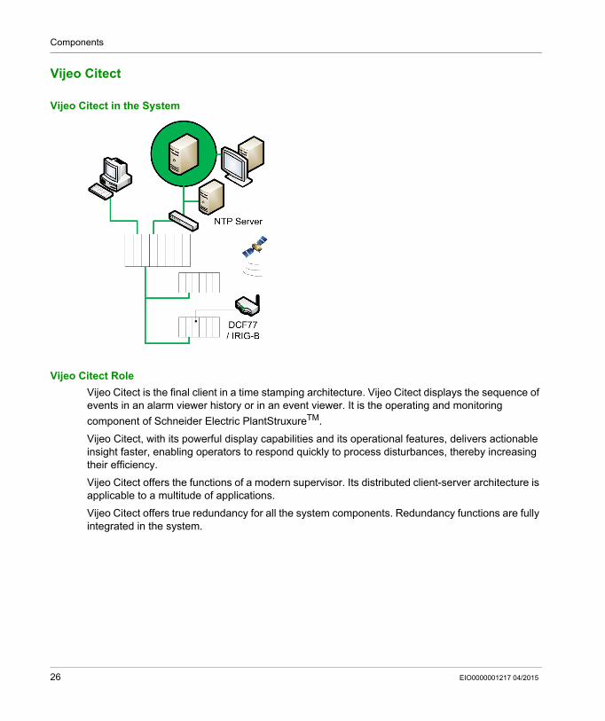
3rd Party Client SCADA in the System
3rd Party Client SCADA Role
If the system does not have a Vijeo Citect, a 3rd party client SCADA can be used to monitor time stamping events through the OPC DA interface.
A 3rd party client SCADA needs to use OFS software services to implement the system time stamping solution.
EIO0000001217 04/2015 27
Components
Time Synchronization
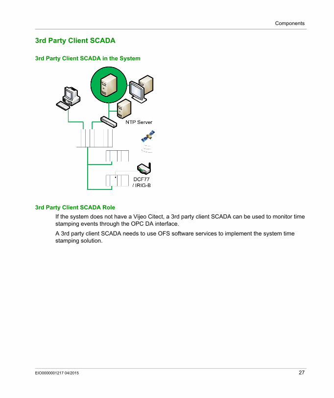
Time Synchronization in the System
Time Synchronization
Time synchronization is a key point in the system time stamping solution. Time synchronization between the time stamping event sources (using different external source clocks) is the prerequisites to have a functional time stamping solution.
Time synchronization means: Vijeo Citect / OFS client: NTP server BMX ERT 1604 T: DCF77 or IRIG-B 004/5/6/7 external clock BM• CRA 312 10: NTP server BME P58 ••••: NTP server
28 EIO0000001217 04/2015

Components
OFS
OFS in the System
OFS Role
OFS software allows access to real-time PLC data. It is a multi-PLC data server. OFS allows to read the time stamping event buffers in the sources and to transmit them to the SCADA via an OPC DA interface.
OFS software offers communication with most Schneider Electric PLCs and is able to browse dynamically objects from Unity Pro software or directly from the PLC.
OFS is located on the control network in the system and if you are using Vijeo Citect it is recommended to install this software on the same PC as OFS.
EIO0000001217 04/2015 29
Components
Unity Pro
Unity Pro Software in the System
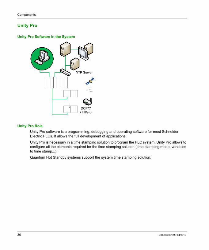
Unity Pro Role
Unity Pro software is a programming, debugging and operating software for most Schneider Electric PLCs. It allows the full development of applications.
Unity Pro is necessary in a time stamping solution to program the PLC system. Unity Pro allows to configure all the elements required for the time stamping solution (time stamping mode, variables to time stamp...).
Quantum Hot Standby systems support the system time stamping solution.
30 EIO0000001217 04/2015

Components
BME P58 xxxx CPU
BME P58 xxxx In the System
BME P58 xxxx Role
The BME P58 •••• CPU is able to time stamp some internal variables (firmware version ≥ 2.00).
The CPU evaluates internal variables selected for time stamping periodically during the MAST task. If a change is detected, the variable is time stamped and stored in the module internal local event buffer.
For time stamping application, the CPU either needs a link to an accurate NTP server time source or uses its internal NTP server depending on the architecture.
BME P58 xxxx Internal Variables for Time Stamping
Application variables that can be time stamped: Simple unlocated variable of BOOL or EBOOL type. For example: MyVar. Simple located variable with symbol of BOOL type. For example: MyVar mapped on %S6. Element of DDT or DDDT of BOOL or EBOOL type. For example: MyVar.Element. Element of array of BOOL or EBOOL type. For example: Myarray[0]. Extracted bit of located variable with symbol of BOOL type. For example: MyVar mapped on
%SW51.1.
Application variables that cannot be time stamped: Extracted bit of unlocated variable of WORD.BOOL type. For example: MyVar.5. Extracted bit of element of DDT or DDDT of BOOL type. For example: MyDDT.ExtractedBit2.
EIO0000001217 04/2015 31
Components
BMX ERT 1604 T Module
BMX ERT 1604 T in the System
BMX ERT 1604 T Role
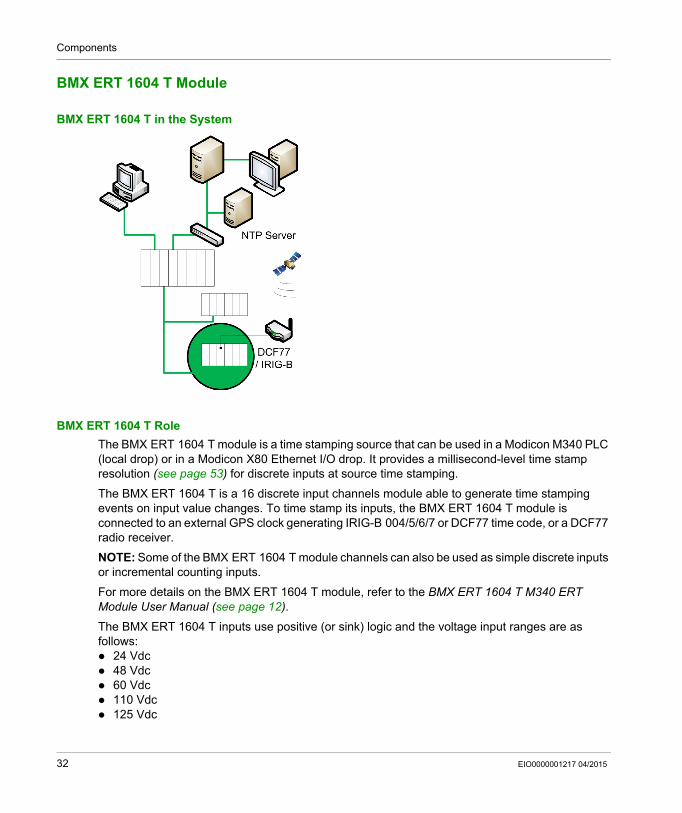
The BMX ERT 1604 T module is a time stamping source that can be used in a Modicon M340 PLC (local drop) or in a Modicon X80 Ethernet I/O drop. It provides a millisecond-level time stamp resolution (see page 53) for discrete inputs at source time stamping.
The BMX ERT 1604 T is a 16 discrete input channels module able to generate time stamping events on input value changes. To time stamp its inputs, the BMX ERT 1604 T module is connected to an external GPS clock generating IRIG-B 004/5/6/7 or DCF77 time code, or a DCF77 radio receiver.
NOTE: Some of the BMX ERT 1604 T module channels can also be used as simple discrete inputs or incremental counting inputs.
For more details on the BMX ERT 1604 T module, refer to the BMX ERT 1604 T M340 ERT Module User Manual (see page 12).
The BMX ERT 1604 T inputs use positive (or sink) logic and the voltage input ranges are as follows: 24 Vdc 48 Vdc 60 Vdc 110 Vdc 125 Vdc
32 EIO0000001217 04/2015
Components
BMx CRA 312 10 Module
BMx CRA 312 10 In the System
BMx CRA 312 10 Role
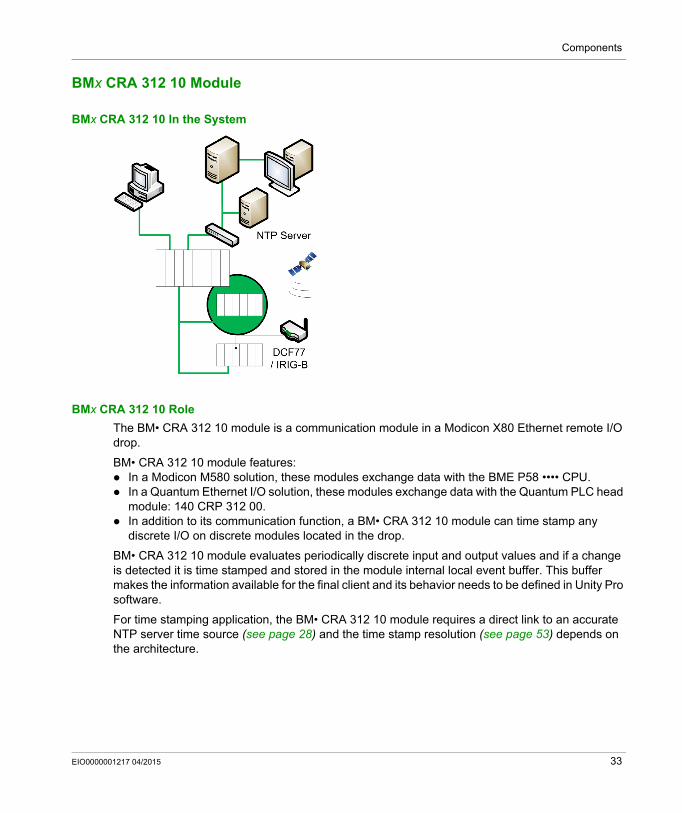
The BM• CRA 312 10 module is a communication module in a Modicon X80 Ethernet remote I/O drop.
BM• CRA 312 10 module features: In a Modicon M580 solution, these modules exchange data with the BME P58 •••• CPU. In a Quantum Ethernet I/O solution, these modules exchange data with the Quantum PLC head
module: 140 CRP 312 00. In addition to its communication function, a BM• CRA 312 10 module can time stamp any
discrete I/O on discrete modules located in the drop.
BM• CRA 312 10 module evaluates periodically discrete input and output values and if a change is detected it is time stamped and stored in the module internal local event buffer. This buffer makes the information available for the final client and its behavior needs to be defined in Unity Pro software.
For time stamping application, the BM• CRA 312 10 module requires a direct link to an accurate NTP server time source (see page 28) and the time stamp resolution (see page 53) depends on the architecture.
EIO0000001217 04/2015 33
Components
Discrete Inputs and Outputs
The BM• CRA 312 10 module is able to time stamp any discrete module located in the drop.
Compatible Modicon X80 discrete modules:
Modules Reference
BMX DAI 0805 BMX DDI 1602 BMX DDM 16022 BMX DDO 1602 BMX DRA 0804
BMX DAI 1602 BMX DDI 1603 BMX DDM 16025 BMX DDO 1612 BMX DRA 0805
BMX DAI 1603 BMX DDI 1604 BMX DDM 3202K BMX DDO 3202K BMX DRA 1605
BMX DAI 1604 BMX DDI 3202K BMX DDO 6402K
BMX DAO 1605 BMX DDI 6402K
34 EIO0000001217 04/2015
Components
Router
Router in the System
Router Role
The router is a device that transmits data between different Ethernet networks (a control network and a device network for example).
NOTE: The router allows a direct communication path between the sources of time stamped events and the final client (SCADA) via OFS.
Router Modules
Routers that can be used in a time stamping solution: In the Ethernet control network, any IP router. In the Quantum PLC local rack, a 140 NOC 781 00 control head module
For more details on the 140 NOC 781 00 module, refer to Quantum EIO, Control Network, Installation and Configuration Guide.
EIO0000001217 04/2015 35
Components
Modicon M340 Ethernet Communication Modules in a Local Drop
Modicon M340 Ethernet Local Drop Communication Module in the System
Communication Modules
For time stamping with a BMX ERT 1604 T in a Modicon M340 PLC (local drop), one of the following Ethernet communication modules is required to interface the BMX ERT 1604 T with the SCADA / OFS: BMX NOC 0401 BMX NOE 0100 BMX NOE 0110
For more details on the Modicon M340 Ethernet communication modules, refer to the Modicon M340 for Ethernet, Communications Modules and Processors, User Manual (see page 12) and Modicon M340, BMX NOC 0401 Ethernet Communication Module, User Manual (see page 12).
36 EIO0000001217 04/2015
System Time Stamping
Components Versions
EIO0000001217 04/2015
Components Versions
Chapter 3Components Versions
Components Version
General
The following table shows the system time stamping component required versions:
Component Version
Vijeo Citect Recommended version: 7.30 (or later)
OFS 3.40 or later
OFSOPC driver 2.05.09.001 or later
Unity Pro Software 7.0 or later
BME P58 •••• firmware 2.00 or later
BMX ERT 1604 T firmware 1.1 or later
BMX CRA 312 10 firmware 1.30 or later
BME CRA 312 10 firmware 1.00 or later
140 NOC 781 00 firmware 1.0 or later
140 CRP 312 00 firmware 2.0 or later
BMX NOC 0401 firmware 2.01 or later
BMX NOE 0100 firmware 2.60 or later
BMX NOE 0110 firmware 5.50 or later
EIO0000001217 04/2015 37

Components Versions
38 EIO0000001217 04/2015
System Time Stamping
Architecture
EIO0000001217 04/2015
Architecture Examples
Chapter 4Architecture Examples
Overview
This chapter provides typical time stamping architectures.
What Is in This Chapter?
This chapter contains the following topics:
Topic Page
Time Stamping Typical Architecture 40
Modicon M580 Typical Architecture 42
Modicon M340 Typical Architecture 46
Modicon Quantum Typical Architecture 47
Redundant Architectures 50
EIO0000001217 04/2015 39
Architecture
Time Stamping Typical Architecture
Overview
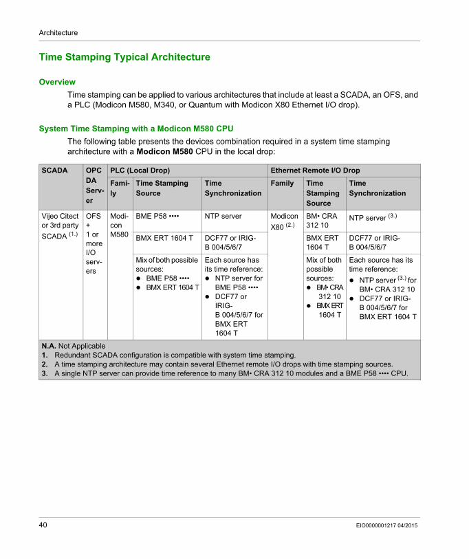
Time stamping can be applied to various architectures that include at least a SCADA, an OFS, and a PLC (Modicon M580, M340, or Quantum with Modicon X80 Ethernet I/O drop).
System Time Stamping with a Modicon M580 CPU
The following table presents the devices combination required in a system time stamping architecture with a Modicon M580 CPU in the local drop:
SCADA OPC DAServ-er
PLC (Local Drop) Ethernet Remote I/O Drop
Fami-ly
Time Stamping Source
Time Synchronization
Family Time Stamping Source
Time Synchronization
Vijeo Citect or 3rd party
SCADA (1.)
OFS+1 or more I/O serv-ers
Modi-con M580
BME P58 •••• NTP server Modicon
X80 (2.)
BM• CRA312 10
NTP server (3.)
BMX ERT 1604 T DCF77 or IRIG-B 004/5/6/7
BMX ERT1604 T
DCF77 or IRIG-B 004/5/6/7
Mix of both possible sources: BME P58 •••• BMX ERT 1604 T
Each source has its time reference: NTP server for
BME P58 •••• DCF77 or
IRIG-B 004/5/6/7 for BMX ERT 1604 T
Mix of both possible sources: BM• CRA
312 10 BMXERT
1604 T
Each source has its time reference:
NTP server (3.) for BM• CRA 312 10
DCF77 or IRIG-B 004/5/6/7 for BMX ERT 1604 T
N.A. Not Applicable1. Redundant SCADA configuration is compatible with system time stamping.2. A time stamping architecture may contain several Ethernet remote I/O drops with time stamping sources.3. A single NTP server can provide time reference to many BM• CRA 312 10 modules and a BME P58 •••• CPU.
40 EIO0000001217 04/2015
Architecture
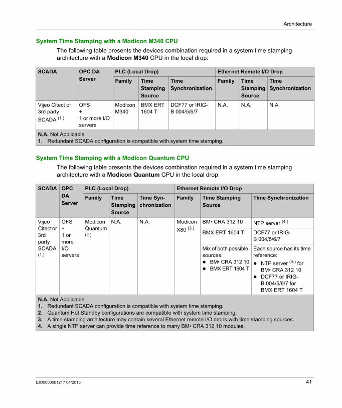
System Time Stamping with a Modicon M340 CPU
The following table presents the devices combination required in a system time stamping architecture with a Modicon M340 CPU in the local drop:
System Time Stamping with a Modicon Quantum CPU
The following table presents the devices combination required in a system time stamping architecture with a Modicon Quantum CPU in the local drop:
SCADA OPC DAServer
PLC (Local Drop) Ethernet Remote I/O Drop
Family Time Stamping Source
Time Synchronization
Family Time Stamping Source
Time Synchronization
Vijeo Citect or 3rd party
SCADA (1.)
OFS+1 or more I/O servers
Modicon M340
BMX ERT1604 T
DCF77 or IRIG-B 004/5/6/7
N.A. N.A. N.A.
N.A. Not Applicable1. Redundant SCADA configuration is compatible with system time stamping.
SCADA OPC DAServer
PLC (Local Drop) Ethernet Remote I/O Drop
Family Time Stamping Source
Time Syn-chronization
Family Time Stamping Source
Time Synchronization
Vijeo Citect or 3rd party SCADA (1.)
OFS+1 or more I/O servers
Modicon Quantum (2.)
N.A. N.A. Modicon
X80 (3.)
BM• CRA 312 10 NTP server (4.)
BMX ERT 1604 T DCF77 or IRIG-B 004/5/6/7
Mix of both possible sources: BM• CRA 312 10 BMX ERT 1604 T
Each source has its time reference:
NTP server (4.) for BM• CRA 312 10
DCF77 or IRIG-B 004/5/6/7 for BMX ERT 1604 T
N.A. Not Applicable1. Redundant SCADA configuration is compatible with system time stamping.2. Quantum Hot Standby configurations are compatible with system time stamping.3. A time stamping architecture may contain several Ethernet remote I/O drops with time stamping sources.4. A single NTP server can provide time reference to many BM• CRA 312 10 modules.
EIO0000001217 04/2015 41
Architecture
Modicon M580 Typical Architecture
Overview
The following topics present graphically some of the devices combination allowed in a system time stamping architecture (it is not an exhaustive list, it represents typical application examples).
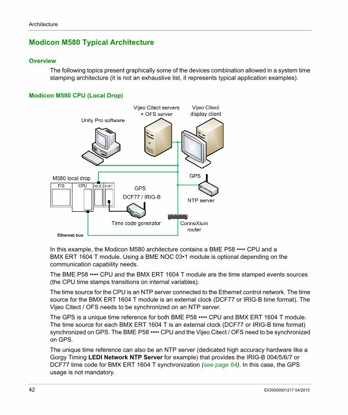
Modicon M580 CPU (Local Drop)
In this example, the Modicon M580 architecture contains a BME P58 •••• CPU and a BMX ERT 1604 T module. Using a BME NOC 03•1 module is optional depending on the communication capability needs.
The BME P58 •••• CPU and the BMX ERT 1604 T module are the time stamped events sources (the CPU time stamps transitions on internal variables).
The time source for the CPU is an NTP server connected to the Ethernet control network. The time source for the BMX ERT 1604 T module is an external clock (DCF77 or IRIG-B time format). The Vijeo Citect / OFS needs to be synchronized on an NTP server.
The GPS is a unique time reference for both BME P58 •••• CPU and BMX ERT 1604 T module. The time source for each BMX ERT 1604 T is an external clock (DCF77 or IRIG-B time format) synchronized on GPS. The BME P58 •••• CPU and the Vijeo Citect / OFS need to be synchronized on GPS.
The unique time reference can also be an NTP server (dedicated high accuracy hardware like a Gorgy Timing LEDI Network NTP Server for example) that provides the IRIG-B 004/5/6/7 or DCF77 time code for BMX ERT 1604 T synchronization (see page 64). In this case, the GPS usage is not mandatory.
42 EIO0000001217 04/2015
Architecture
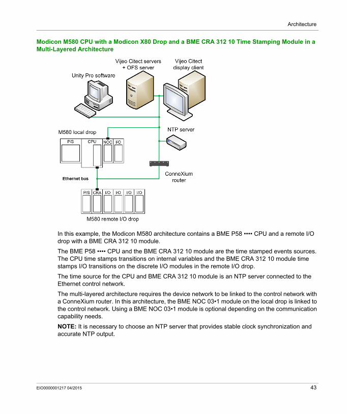
Modicon M580 CPU with a Modicon X80 Drop and a BME CRA 312 10 Time Stamping Module in a Multi-Layered Architecture
In this example, the Modicon M580 architecture contains a BME P58 •••• CPU and a remote I/O drop with a BME CRA 312 10 module.
The BME P58 •••• CPU and the BME CRA 312 10 module are the time stamped events sources. The CPU time stamps transitions on internal variables and the BME CRA 312 10 module time stamps I/O transitions on the discrete I/O modules in the remote I/O drop.
The time source for the CPU and BME CRA 312 10 module is an NTP server connected to the Ethernet control network.
The multi-layered architecture requires the device network to be linked to the control network with a ConneXium router. In this architecture, the BME NOC 03•1 module on the local drop is linked to the control network. Using a BME NOC 03•1 module is optional depending on the communication capability needs.
NOTE: It is necessary to choose an NTP server that provides stable clock synchronization and accurate NTP output.
EIO0000001217 04/2015 43
Architecture
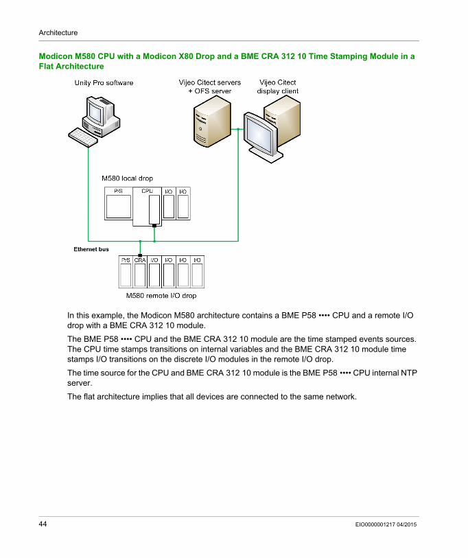
Modicon M580 CPU with a Modicon X80 Drop and a BME CRA 312 10 Time Stamping Module in a Flat Architecture
In this example, the Modicon M580 architecture contains a BME P58 •••• CPU and a remote I/O drop with a BME CRA 312 10 module.
The BME P58 •••• CPU and the BME CRA 312 10 module are the time stamped events sources. The CPU time stamps transitions on internal variables and the BME CRA 312 10 module time stamps I/O transitions on the discrete I/O modules in the remote I/O drop.
The time source for the CPU and BME CRA 312 10 module is the BME P58 •••• CPU internal NTP server.
The flat architecture implies that all devices are connected to the same network.
44 EIO0000001217 04/2015
Architecture
Modicon M580 CPU with a Modicon X80 Drop Including BMX ERT 1604 T and BMx CRA 312 10 Modules
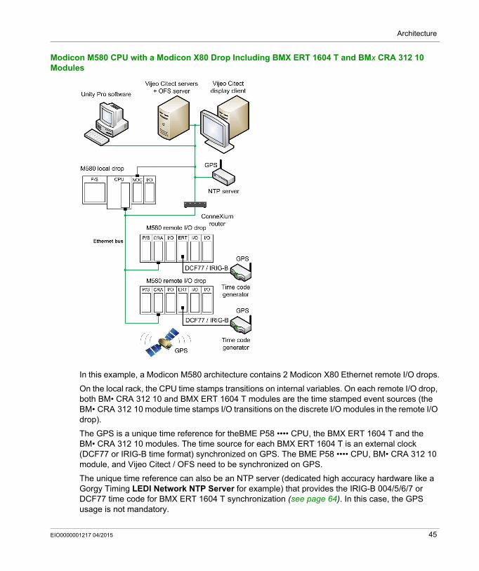
In this example, a Modicon M580 architecture contains 2 Modicon X80 Ethernet remote I/O drops.
On the local rack, the CPU time stamps transitions on internal variables. On each remote I/O drop, both BM• CRA 312 10 and BMX ERT 1604 T modules are the time stamped event sources (the BM• CRA 312 10 module time stamps I/O transitions on the discrete I/O modules in the remote I/O drop).
The GPS is a unique time reference for theBME P58 •••• CPU, the BMX ERT 1604 T and the BM• CRA 312 10 modules. The time source for each BMX ERT 1604 T is an external clock (DCF77 or IRIG-B time format) synchronized on GPS. The BME P58 •••• CPU, BM• CRA 312 10 module, and Vijeo Citect / OFS need to be synchronized on GPS.
The unique time reference can also be an NTP server (dedicated high accuracy hardware like a Gorgy Timing LEDI Network NTP Server for example) that provides the IRIG-B 004/5/6/7 or DCF77 time code for BMX ERT 1604 T synchronization (see page 64). In this case, the GPS usage is not mandatory.
EIO0000001217 04/2015 45
Architecture
Modicon M340 Typical Architecture
Overview
The following topics present graphically some of the devices combination allowed in a system time stamping architecture (it is not an exhaustive list, it represents typical application examples).
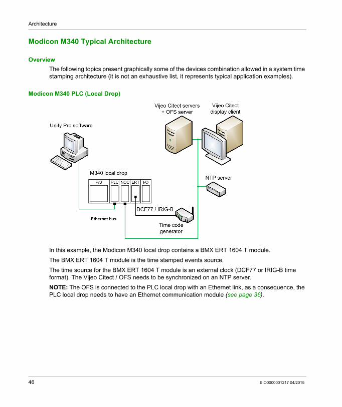
Modicon M340 PLC (Local Drop)
In this example, the Modicon M340 local drop contains a BMX ERT 1604 T module.
The BMX ERT 1604 T module is the time stamped events source.
The time source for the BMX ERT 1604 T module is an external clock (DCF77 or IRIG-B time format). The Vijeo Citect / OFS needs to be synchronized on an NTP server.
NOTE: The OFS is connected to the PLC local drop with an Ethernet link, as a consequence, the PLC local drop needs to have an Ethernet communication module (see page 36).
46 EIO0000001217 04/2015
Architecture
Modicon Quantum Typical Architecture
Overview
The following topics present graphically some of the devices combination allowed in a system time stamping architecture (it is not an exhaustive list, it represents typical application examples).
Quantum PLC with a Modicon X80 Drop and a BMX CRA 312 10 Time Stamping Module
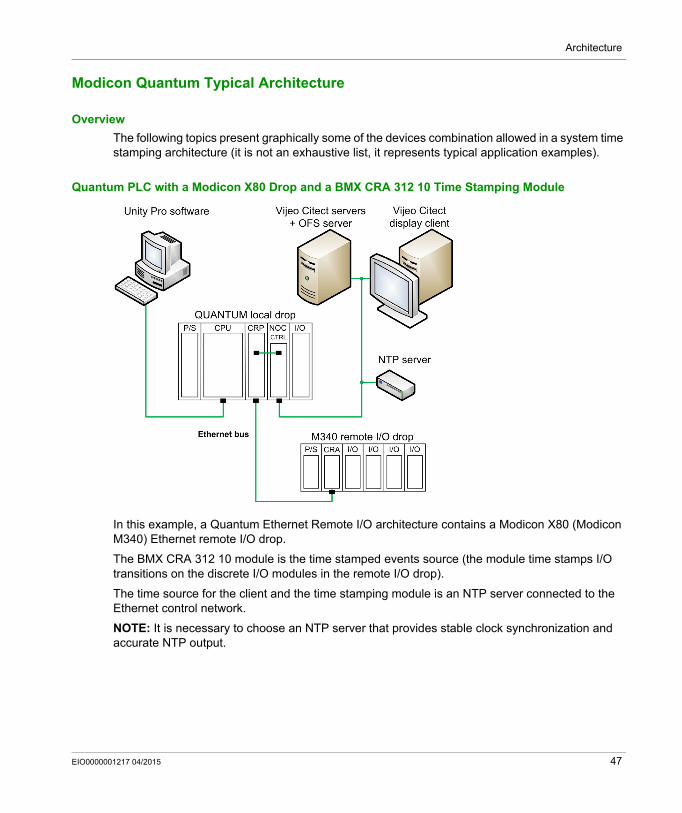
In this example, a Quantum Ethernet Remote I/O architecture contains a Modicon X80 (Modicon M340) Ethernet remote I/O drop.
The BMX CRA 312 10 module is the time stamped events source (the module time stamps I/O transitions on the discrete I/O modules in the remote I/O drop).
The time source for the client and the time stamping module is an NTP server connected to the Ethernet control network.
NOTE: It is necessary to choose an NTP server that provides stable clock synchronization and accurate NTP output.
EIO0000001217 04/2015 47
Architecture
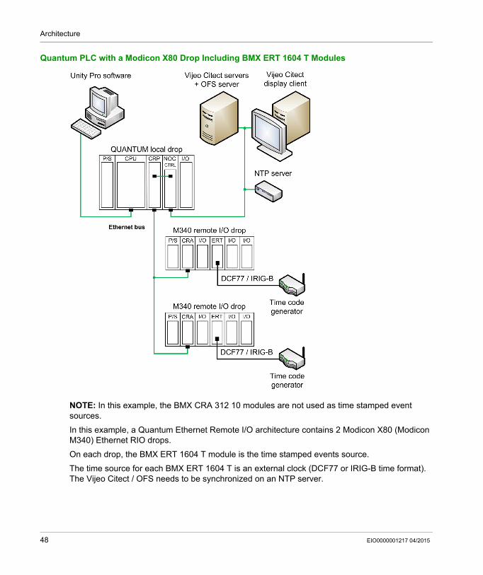
Quantum PLC with a Modicon X80 Drop Including BMX ERT 1604 T Modules
NOTE: In this example, the BMX CRA 312 10 modules are not used as time stamped event sources.
In this example, a Quantum Ethernet Remote I/O architecture contains 2 Modicon X80 (Modicon M340) Ethernet RIO drops.
On each drop, the BMX ERT 1604 T module is the time stamped events source.
The time source for each BMX ERT 1604 T is an external clock (DCF77 or IRIG-B time format). The Vijeo Citect / OFS needs to be synchronized on an NTP server.
48 EIO0000001217 04/2015
Architecture
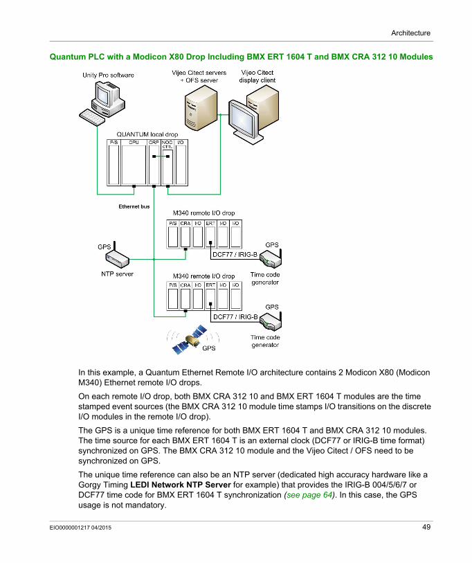
Quantum PLC with a Modicon X80 Drop Including BMX ERT 1604 T and BMX CRA 312 10 Modules
In this example, a Quantum Ethernet Remote I/O architecture contains 2 Modicon X80 (Modicon M340) Ethernet remote I/O drops.
On each remote I/O drop, both BMX CRA 312 10 and BMX ERT 1604 T modules are the time stamped event sources (the BMX CRA 312 10 module time stamps I/O transitions on the discrete I/O modules in the remote I/O drop).
The GPS is a unique time reference for both BMX ERT 1604 T and BMX CRA 312 10 modules. The time source for each BMX ERT 1604 T is an external clock (DCF77 or IRIG-B time format) synchronized on GPS. The BMX CRA 312 10 module and the Vijeo Citect / OFS need to be synchronized on GPS.
The unique time reference can also be an NTP server (dedicated high accuracy hardware like a Gorgy Timing LEDI Network NTP Server for example) that provides the IRIG-B 004/5/6/7 or DCF77 time code for BMX ERT 1604 T synchronization (see page 64). In this case, the GPS usage is not mandatory.
EIO0000001217 04/2015 49
Architecture
Redundant Architectures
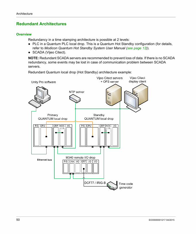
Overview
Redundancy in a time stamping architecture is possible at 2 levels: PLC in a Quantum PLC local drop. This is a Quantum Hot Standby configuration (for details,
refer to Modicon Quantum Hot Standby System User Manual (see page 12)). SCADA (Vijeo Citect).
NOTE: Redundant SCADA servers are recommended to prevent loss of data. If there is no SCADA redundancy, some events may be lost in case of communication problem between SCADA servers.
Redundant Quantum local drop (Hot Standby) architecture example:
50 EIO0000001217 04/2015

Architecture
Redundant Vijeo Citect architecture example:
EIO0000001217 04/2015 51

Architecture
52 EIO0000001217 04/2015
System Time Stamping
Performances
EIO0000001217 04/2015
Performances
Chapter 5Performances
Performances
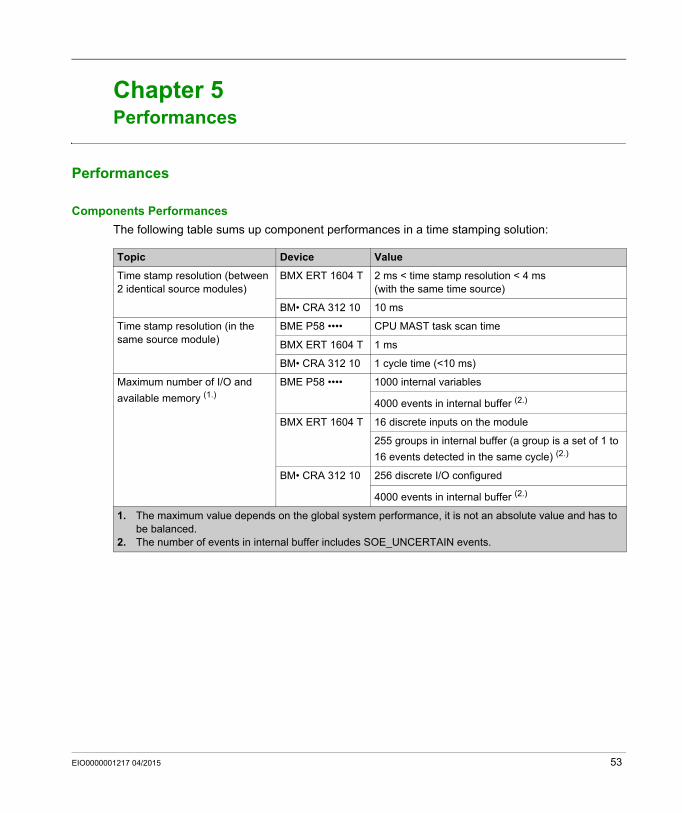
Components Performances
The following table sums up component performances in a time stamping solution:
Topic Device Value
Time stamp resolution (between 2 identical source modules)
BMX ERT 1604 T 2 ms < time stamp resolution < 4 ms(with the same time source)
BM• CRA 312 10 10 ms
Time stamp resolution (in the same source module)
BME P58 •••• CPU MAST task scan time
BMX ERT 1604 T 1 ms
BM• CRA 312 10 1 cycle time (<10 ms)
Maximum number of I/O and
available memory (1.)
BME P58 •••• 1000 internal variables
4000 events in internal buffer (2.)
BMX ERT 1604 T 16 discrete inputs on the module
255 groups in internal buffer (a group is a set of 1 to
16 events detected in the same cycle) (2.)
BM• CRA 312 10 256 discrete I/O configured
4000 events in internal buffer (2.)
1. The maximum value depends on the global system performance, it is not an absolute value and has to be balanced.
2. The number of events in internal buffer includes SOE_UNCERTAIN events.
EIO0000001217 04/2015 53

Performances
System Limitations
The following table sums up system performance in a time stamping solution:
NOTE: OFS Time Stamp Helper (see page 92) is a dedicated tool provided to help the user to define the system capacity based on the events and devices included.
Topic Description Value
Maximum number of BMX ERT 1604 T modules in a Modicon M580 local drop.
BMX ERT 1604 T 9 per drop
Maximum number of BMX ERT 1604 T modules in a Modicon M340 local drop.
BMX ERT 1604 T 9 per drop
Maximum number of devices in an Ethernet remote I/O drop.
BMX ERT 1604 T 9 per drop (1.)
BM• CRA 312 10 1 per drop
Maximum number of devices in the drops controlled by the same PLC and connected to the Ethernet RIO network.
BMX ERT 1604 T 25(2.)
BM• CRA 312 10 31(2.)
Maximum number of sources of events polled by OFS.
A BME P58 •••• CPU, BMX ERT 1604 T module, or BM• CRA 312 10 module count as 1 source
500 sources per second (3.)
Maximum discrete I/Os per PLC 2500 (2.)
OFS polling rate. Minimum OFS polling rate value 250 ms
Maximum number of discrete inputs (and outputs) monitored by the PLC for all the time stamping modules.
For all the BMX ERT 1604 T 400 discrete inputs (2.)
For all the BM• CRA 312 10 2048 discrete I/Os (2.)
1. A BMX ERT 1604 T module contains 4 expert channels. A Modicon X80 drop supports a maximum of 36 expert channels, so it supports a maximum of 9 x BMX ERT 1604 T modules if there is no BMX EHC 0•00 counting module in the drop.
2. The maximum value depends on the global system performance; it is not an absolute value and has to be balanced.
3. The maximum value depends on the CPU capacity and usage of the PC that hosts OFS and I/O server. It is recommended to avoid installation of other CPU or memory consuming applications on this PC.
54 EIO0000001217 04/2015
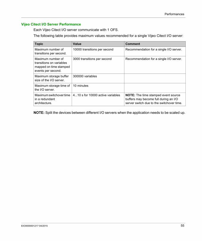
Performances
Vijeo Citect I/O Server Performance
Each Vijeo Citect I/O server communicate with 1 OFS.
The following table provides maximum values recommended for a single Vijeo Citect I/O server:
NOTE: Split the devices between different I/O servers when the application needs to be scaled up.
Topic Value Comment
Maximum number of transitions per second.
10000 transitions per second Recommendation for a single I/O server.
Maximum number of transitions on variables mapped on time stamped events per second.
3000 transitions per second Recommendation for a single I/O server.
Maximum storage buffer size of the I/O server.
300000 variables
Maximum storage time of the I/O server.
10 minutes
Maximum switchover time in a redundant architecture.
4...10 s for 10000 active variables NOTE: The time stamped event source buffers may become full during an I/O server switch due to the switchover time.
EIO0000001217 04/2015 55

Performances
56 EIO0000001217 04/2015
System Time Stamping
Design and Configuration
EIO0000001217 04/2015
Design and Configuration Phases
Part IIIDesign and Configuration Phases
Introduction
This part presents the phases required to design and configure the system time stamping from service activation to diagnostic.
What Is in This Part?
This part contains the following chapters:
Chapter Chapter Name Page
6 Selecting the Time Stamping Module 59
7 Selecting and Setting Time Synchronization 61
8 Activating System Time Stamping Service 71
9 Selecting and Configuring the Variables to Time Stamp 79
10 Selecting the Communication Parameters 91
11 Setting Vijeo Citect Parameters 95
EIO0000001217 04/2015 57

Design and Configuration
58 EIO0000001217 04/2015
System Time Stamping
Selecting Time Stamping Module
EIO0000001217 04/2015
Selecting the Time Stamping Module
Chapter 6Selecting the Time Stamping Module
Time Resolution
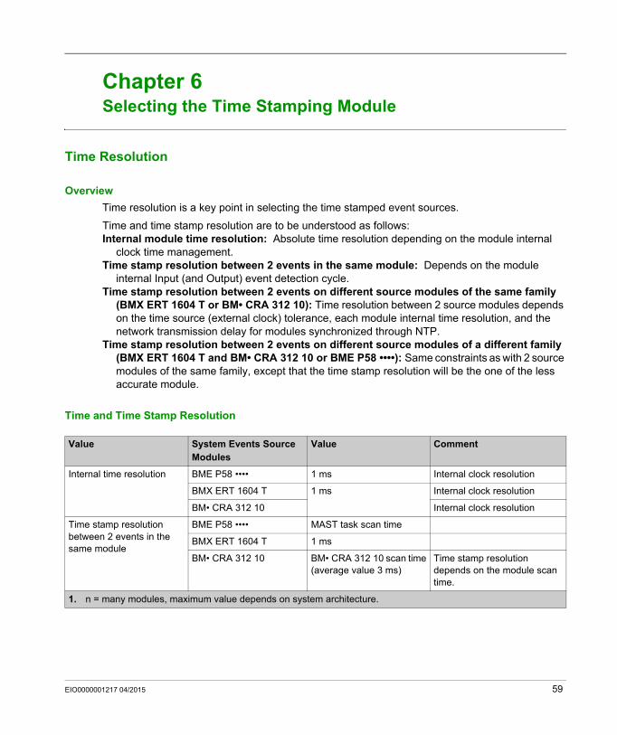
Overview
Time resolution is a key point in selecting the time stamped event sources.
Time and time stamp resolution are to be understood as follows:Internal module time resolution: Absolute time resolution depending on the module internal
clock time management.Time stamp resolution between 2 events in the same module: Depends on the module
internal Input (and Output) event detection cycle.Time stamp resolution between 2 events on different source modules of the same family
(BMX ERT 1604 T or BM• CRA 312 10): Time resolution between 2 source modules depends on the time source (external clock) tolerance, each module internal time resolution, and the network transmission delay for modules synchronized through NTP.
Time stamp resolution between 2 events on different source modules of a different family (BMX ERT 1604 T and BM• CRA 312 10 or BME P58 ••••): Same constraints as with 2 source modules of the same family, except that the time stamp resolution will be the one of the less accurate module.
Time and Time Stamp Resolution
Value System Events Source Modules
Value Comment
Internal time resolution BME P58 •••• 1 ms Internal clock resolution
BMX ERT 1604 T 1 ms Internal clock resolution
BM• CRA 312 10 Internal clock resolution
Time stamp resolution between 2 events in the same module
BME P58 •••• MAST task scan time
BMX ERT 1604 T 1 ms
BM• CRA 312 10 BM• CRA 312 10 scan time(average value 3 ms)
Time stamp resolution depends on the module scan time.
1. n = many modules, maximum value depends on system architecture.
EIO0000001217 04/2015 59
Selecting Time Stamping Module
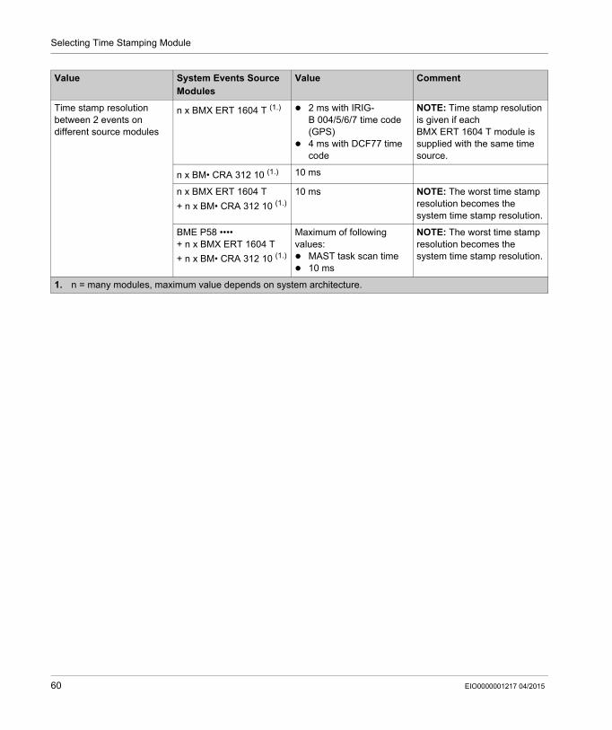
Time stamp resolution between 2 events on different source modules
n x BMX ERT 1604 T (1.) 2 ms with IRIG-B 004/5/6/7 time code (GPS)
4 ms with DCF77 time code
NOTE: Time stamp resolution is given if each BMX ERT 1604 T module is supplied with the same time source.
n x BM• CRA 312 10 (1.) 10 ms
n x BMX ERT 1604 T
+ n x BM• CRA 312 10 (1.)
10 ms NOTE: The worst time stamp resolution becomes the system time stamp resolution.
BME P58 ••••+ n x BMX ERT 1604 T
+ n x BM• CRA 312 10 (1.)
Maximum of following values: MAST task scan time 10 ms
NOTE: The worst time stamp resolution becomes the system time stamp resolution.
Value System Events Source Modules
Value Comment
1. n = many modules, maximum value depends on system architecture.
60 EIO0000001217 04/2015
System Time Stamping
Selecting and Setting Time Synchronization
EIO0000001217 04/2015
Selecting and Setting Time Synchronization
Chapter 7Selecting and Setting Time Synchronization
Overview
This chapter describes the available time sources, the time synchronization principles, and corresponding software settings.
What Is in This Chapter?
This chapter contains the following topics:
Topic Page
Selecting the Time Source 62
Unity Pro Project Setting 65
BME P58 xxxx Clock Settings in Unity Pro 66
BMX ERT 1604 T Clock Settings in Unity Pro 68
BMx CRA 312 10 Clock Settings in Unity Pro 69
EIO0000001217 04/2015 61
Selecting and Setting Time Synchronization
Selecting the Time Source
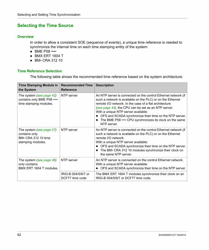
Overview
In order to allow a consistent SOE (sequence of events), a unique time reference is needed to synchronize the internal time on each time stamping entity of the system: BME P58 •••• BMX ERT 1604 T BM• CRA 312 10
Time Reference Selection
The following table shows the recommended time reference based on the system architecture:
Time Stamping Module in the System
Recommended Time Reference
Description
The system (see page 42) contains only BME P58 •••• time stamping modules.
NTP server An NTP server is connected on the control Ethernet network (if such a network is available on the PLC) or on the Ethernet remote I/O network. In the case of a flat architecture (see page 44), the CPU can be set as an NTP server.With a unique NTP server available: OFS and SCADA synchronize their time on the NTP server. The BME P58 •••• CPU synchronizes its clock on the same
NTP server.
The system (see page 47) contains only BM• CRA 312 10 time stamping modules.
NTP server An NTP server is connected on the control Ethernet network (if such a network is available on the PLC) or on the Ethernet remote I/O network.With a unique NTP server available: OFS and SCADA synchronize their time on the NTP server. The BM• CRA 312 10 modules synchronize their clock on
the same NTP server.
The system (see page 46) only contains BMX ERT 1604 T modules.
NTP server An NTP server is connected on the control Ethernet network.With a unique NTP server available: OFS and SCADA synchronize their time on the NTP server.
IRIG-B 004/5/6/7 or DCF77 time code
The BMX ERT 1604 T modules synchronize their clock on an IRIG-B 004/5/6/7 or DCF77 time code.
62 EIO0000001217 04/2015
Selecting and Setting Time Synchronization
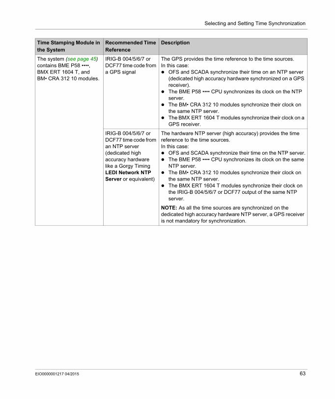
The system (see page 45) contains BME P58 ••••, BMX ERT 1604 T, and BM• CRA 312 10 modules.
IRIG-B 004/5/6/7 or DCF77 time code from a GPS signal
The GPS provides the time reference to the time sources.In this case: OFS and SCADA synchronize their time on an NTP server
(dedicated high accuracy hardware synchronized on a GPS receiver).
The BME P58 •••• CPU synchronizes its clock on the NTP server.
The BM• CRA 312 10 modules synchronize their clock on the same NTP server.
The BMX ERT 1604 T modules synchronize their clock on a GPS receiver.
IRIG-B 004/5/6/7 or DCF77 time code from an NTP server (dedicated high accuracy hardware like a Gorgy Timing LEDI Network NTP Server or equivalent)
The hardware NTP server (high accuracy) provides the time reference to the time sources.In this case: OFS and SCADA synchronize their time on the NTP server. The BME P58 •••• CPU synchronizes its clock on the same
NTP server. The BM• CRA 312 10 modules synchronize their clock on
the same NTP server. The BMX ERT 1604 T modules synchronize their clock on
the IRIG-B 004/5/6/7 or DCF77 output of the same NTP server.
NOTE: As all the time sources are synchronized on the dedicated high accuracy hardware NTP server, a GPS receiver is not mandatory for synchronization.
Time Stamping Module in the System
Recommended Time Reference
Description
EIO0000001217 04/2015 63
Selecting and Setting Time Synchronization
Time Sources for Modules
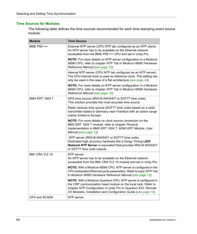
The following table defines the time sources recommended for each time stamping event source module:
Module Time Source
BME P58 •••• External NTP server (CPU NTP tab configured as an NTP client).An NTP server has to be available on the Ethernet network accessible from the BME P58 •••• CPU and set in Unity Pro.
NOTE: For more details on NTP server configuration in a Modicon M580 CPU, refer to chapter NTP Tab in Modicon M580 Hardware Reference Manual (see page 12).
Internal NTP server (CPU NTP tab configured as an NTP server).The CPU internal clock is used as reference clock. This setting can only be used in the case of a flat architecture (see page 44).
NOTE: For more details on NTP server configuration in a Modicon M580 CPU, refer to chapter NTP Tab in Modicon M580 Hardware Reference Manual (see page 12).
BMX ERT 1604 T GPS time source (IRIG-B 004/5/6/7 or DCF77 time code).This solution provides the most accurate time source.
Radio receiver time source (DCF77 time code) based on a radio transmitter based in Germany near Frankfurt with an action range mainly limited to Europe.
NOTE: For more details on clock source connection on the BMX ERT 1604 T module, refer to chapter Physical Implementation in BMX ERT 1604 T, M340 ERT Module, User Manual (see page 12).
NTP server (IRIG-B 004/5/6/7 or DCF77 time code).Dedicated high accuracy hardware like a Gorgy Timing LEDI Network NTP Server or equivalent that provides IRIG-B 004/5/6/7 or DCF77 time code outputs.
BM• CRA 312 10 NTP server.An NTP server has to be available on the Ethernet network accessible from the BM• CRA 312 10 module and set in Unity Pro.
NOTE: With a Modicon M580 CPU, NTP server is configured in the CPU embedded Ethernet ports parameters. Refer to topic NTP Tab in Modicon M580 Hardware Reference Manual (see page 12).
NOTE: With a Modicon Quantum CPU, NTP server is configured in the CRP communication head module on the local rack. Refer to chapter NTP Configuration in Unity Pro in Quantum EIO, Remote I/O Modules, Installation and Configuration Guide (see page 12).
OFS and SCADA NTP server.
64 EIO0000001217 04/2015

Selecting and Setting Time Synchronization
Unity Pro Project Setting
Time Zone
Adjust Project Settings in Unity Pro (see page 73) and set time zone parameters.
EIO0000001217 04/2015 65
Selecting and Setting Time Synchronization
BME P58 xxxx Clock Settings in Unity Pro
BME P58 xxxx Clock
The CPU clock for internal variables time stamping is provided by either an external or internal time source.External time source: The CPU is set as an NTP client and synchronizes its internal clock on an
Ethernet NTP server usually located on the control network.Internal time source: The CPU is set as an NTP server. It uses its internal clock and acts as an
Ethernet NTP server for devices connected to the Ethernet network on which the CPU is connected.
Setting the CPU as an NTP Client in Unity Pro
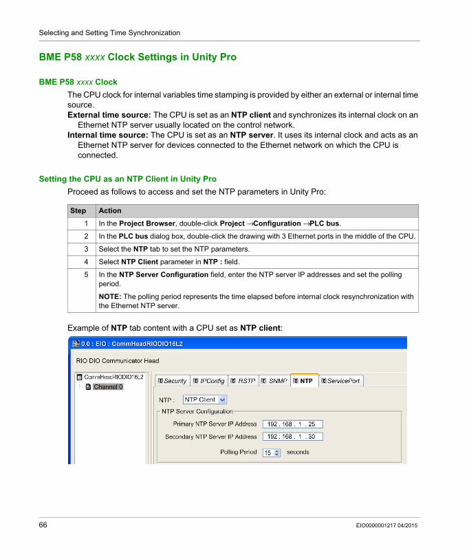
Proceed as follows to access and set the NTP parameters in Unity Pro:
Example of NTP tab content with a CPU set as NTP client:
Step Action
1 In the Project Browser, double-click Project → Configuration → PLC bus.
2 In the PLC bus dialog box, double-click the drawing with 3 Ethernet ports in the middle of the CPU.
3 Select the NTP tab to set the NTP parameters.
4 Select NTP Client parameter in NTP : field.
5 In the NTP Server Configuration field, enter the NTP server IP addresses and set the polling period.
NOTE: The polling period represents the time elapsed before internal clock resynchronization with the Ethernet NTP server.
66 EIO0000001217 04/2015
Selecting and Setting Time Synchronization
Setting the CPU as an NTP Server in Unity Pro
Proceed as follows to access and set the NTP parameters in Unity Pro:
Step Action
1 In the Project Browser, double-click Project → Configuration → PLC bus.
2 In the PLC bus dialog box, double-click the drawing with 3 Ethernet ports in the middle of the CPU.
3 Select the NTP tab to set the NTP parameters.
4 Select NTP Server parameter in NTP : field.
5 NTP Server Configuration field enables to set the polling period.
NOTE: When the CPU is set as an NTP server, the polling period is a parameter used by remote modules in the PAC (for example a BM• CRA 312 10 module). It represents the time elapsed before remote modules internal clock resynchronization with the CPU NTP server.
EIO0000001217 04/2015 67
Selecting and Setting Time Synchronization
BMX ERT 1604 T Clock Settings in Unity Pro
BMX ERT 1604 T Clock
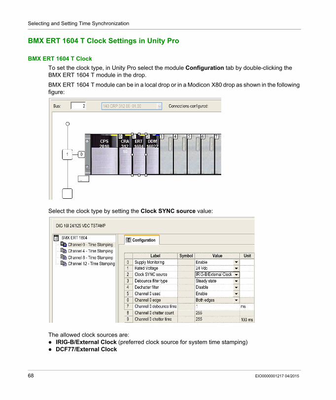
To set the clock type, in Unity Pro select the module Configuration tab by double-clicking the BMX ERT 1604 T module in the drop.
BMX ERT 1604 T module can be in a local drop or in a Modicon X80 drop as shown in the following figure:
Select the clock type by setting the Clock SYNC source value:
The allowed clock sources are: IRIG-B/External Clock (preferred clock source for system time stamping) DCF77/External Clock
68 EIO0000001217 04/2015
Selecting and Setting Time Synchronization
BMx CRA 312 10 Clock Settings in Unity Pro
BMx CRA 312 10 Clock
The BM• CRA 312 10 module clock is provided by an Ethernet NTP server. The server access is configured in the local rack.
NTP Server Settings in Unity Pro With a Modicon M580 CPU
To access the NTP server parameters, select the BME P58 •••• CPU Ethernet ports configuration (see page 66).
EIO0000001217 04/2015 69
Selecting and Setting Time Synchronization
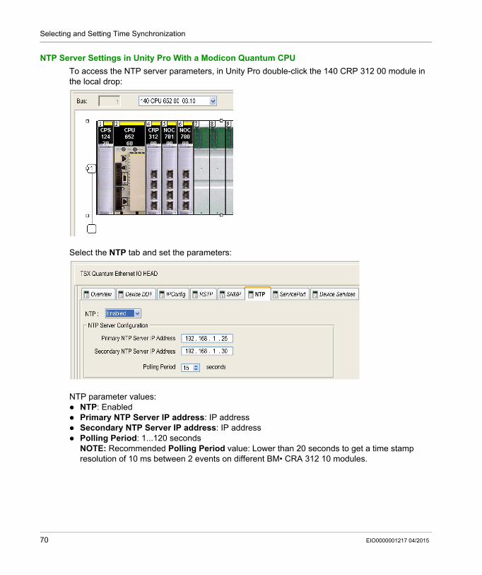
NTP Server Settings in Unity Pro With a Modicon Quantum CPU
To access the NTP server parameters, in Unity Pro double-click the 140 CRP 312 00 module in the local drop:
Select the NTP tab and set the parameters:
NTP parameter values: NTP: Enabled Primary NTP Server IP address: IP address Secondary NTP Server IP address: IP address Polling Period: 1...120 seconds
NOTE: Recommended Polling Period value: Lower than 20 seconds to get a time stamp resolution of 10 ms between 2 events on different BM• CRA 312 10 modules.
70 EIO0000001217 04/2015
System Time Stamping
Service Activation
EIO0000001217 04/2015
Activating System Time Stamping Service
Chapter 8Activating System Time Stamping Service
Overview
This chapter describes the actions performed in order to activate the system time stamping in Unity Pro and OFS software.
What Is in This Chapter?
This chapter contains the following topics:
Topic Page
Unity Pro Settings 72
OFS Settings 76
EIO0000001217 04/2015 71
Service Activation
Unity Pro Settings
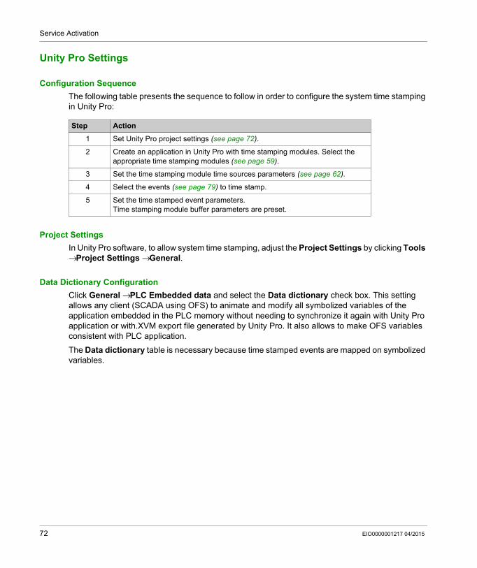
Configuration Sequence
The following table presents the sequence to follow in order to configure the system time stamping in Unity Pro:
Project Settings
In Unity Pro software, to allow system time stamping, adjust the Project Settings by clicking Tools → Project Settings → General.
Data Dictionary Configuration
Click General → PLC Embedded data and select the Data dictionary check box. This setting allows any client (SCADA using OFS) to animate and modify all symbolized variables of the application embedded in the PLC memory without needing to synchronize it again with Unity Pro application or with.XVM export file generated by Unity Pro. It also allows to make OFS variables consistent with PLC application.
The Data dictionary table is necessary because time stamped events are mapped on symbolized variables.
Step Action
1 Set Unity Pro project settings (see page 72).
2 Create an application in Unity Pro with time stamping modules. Select the appropriate time stamping modules (see page 59).
3 Set the time stamping module time sources parameters (see page 62).
4 Select the events (see page 79) to time stamp.
5 Set the time stamped event parameters.Time stamping module buffer parameters are preset.
72 EIO0000001217 04/2015
Service Activation
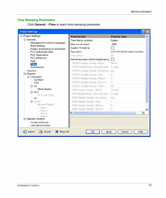
Time Stamping Parameters
Click General → Time to reach time stamping parameter:
EIO0000001217 04/2015 73
Service Activation
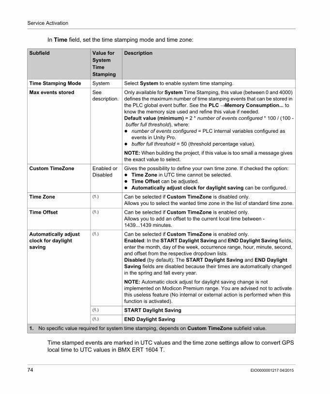
In Time field, set the time stamping mode and time zone:
Time stamped events are marked in UTC values and the time zone settings allow to convert GPS local time to UTC values in BMX ERT 1604 T.
Subfield Value for System Time Stamping
Description
Time Stamping Mode System Select System to enable system time stamping.
Max events stored See description.
Only available for System Time Stamping, this value (between 0 and 4000) defines the maximum number of time stamping events that can be stored in the PLC global event buffer. See the PLC → Memory Consumption... to know the memory size used and refine this value if needed.Default value (minimum) = 2 * number of events configured * 100 / (100 -buffer full threshold), where: number of events configured = PLC internal variables configured as
events in Unity Pro. buffer full threshold = 50 (threshold percentage value).
NOTE: When building the project, if this value is too small a message gives the exact value to select.
Custom TimeZone Enabled or Disabled
Gives the possibility to define your own time zone. If checked the option: Time Zone in UTC time cannot be selected. Time Offset can be adjusted. Automatically adjust clock for daylight saving can be configured.
Time Zone (1.) Can be selected if Custom TimeZone is disabled only.Allows you to select the wanted time zone in the list of standard time zone.
Time Offset (1.) Can be selected if Custom TimeZone is enabled only.Allows you to add an offset to the current local time between -1439...1439 minutes.
Automatically adjust clock for daylight saving
(1.) Can be selected if Custom TimeZone is enabled only.Enabled: In the START Daylight Saving and END Daylight Saving fields, enter the month, day of the week, occurrence range, hour, minute, second, and offset from the respective dropdown lists.Disabled (by default): The START Daylight Saving and END Daylight Saving fields are disabled because their times are automatically changed in the spring and fall every year.
NOTE: Automatic clock adjust for daylight saving change is not implemented on Modicon Premium range. You are advised not to activate this useless feature (No internal or external action is performed when this function is activated).
(1.) START Daylight Saving
(1.) END Daylight Saving
1. No specific value required for system time stamping, depends on Custom TimeZone subfield value.
74 EIO0000001217 04/2015
Service Activation
NOTE: When the source of time stamped events is a BM• CRA 312 10 module, the time zone settings have no influence on time stamped events (the module uses UTC time from the NTP server) but the time zone settings are used for diagnostic purpose (local time is needed).
NOTE: The daylight saving time settings are not applicable to the BMX ERT 1604 T module because this module gets the daylight saving time switching information from the external clock (DCF77 or IRIG-B 004/5/6/7 time code). IRIG-B 004/5/6/7 has to support IEEE-1344 extensions (2004 update) or IEEE C37.118 in order to provide the Daylight Saving Time information.
EIO0000001217 04/2015 75
Service Activation
OFS Settings
Features
The custom OPC property is linked to OPC items with the following definition: Description: time stamped event support PropertyId: 5012 Comment: true if the variable is configured as time stamped event Type: VT_BOOL Values: 1 if the item is a time stamped event and 0 if not
NOTE: For Unity Pro variables configured as TS events, the property value is set to 1 and used by the OPC client to determine which items can be added in the event group.
Time Stamping Events Configuration
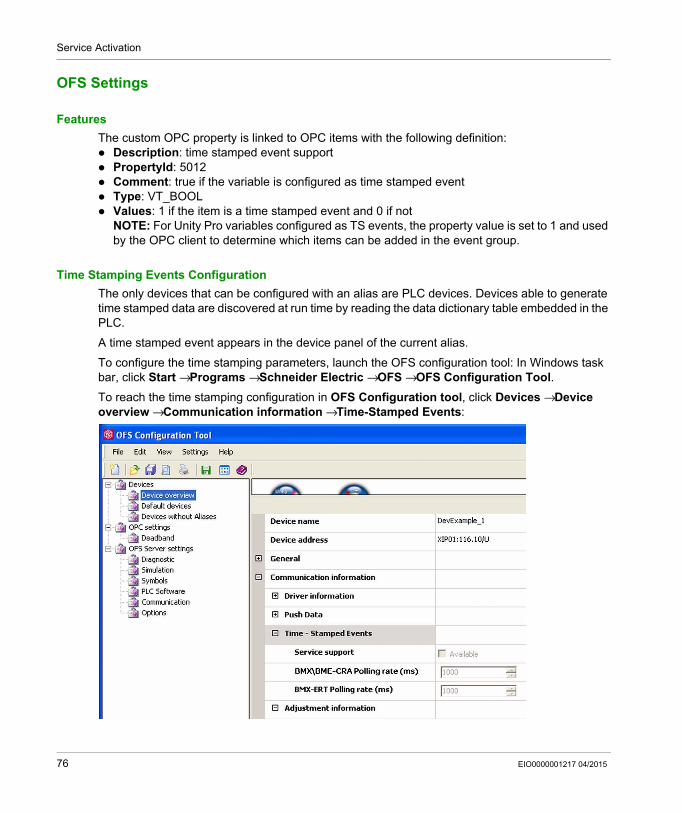
The only devices that can be configured with an alias are PLC devices. Devices able to generate time stamped data are discovered at run time by reading the data dictionary table embedded in the PLC.
A time stamped event appears in the device panel of the current alias.
To configure the time stamping parameters, launch the OFS configuration tool: In Windows task bar, click Start → Programs → Schneider Electric → OFS → OFS Configuration Tool.
To reach the time stamping configuration in OFS Configuration tool, click Devices → Device overview → Communication information → Time-Stamped Events:
76 EIO0000001217 04/2015
Service Activation
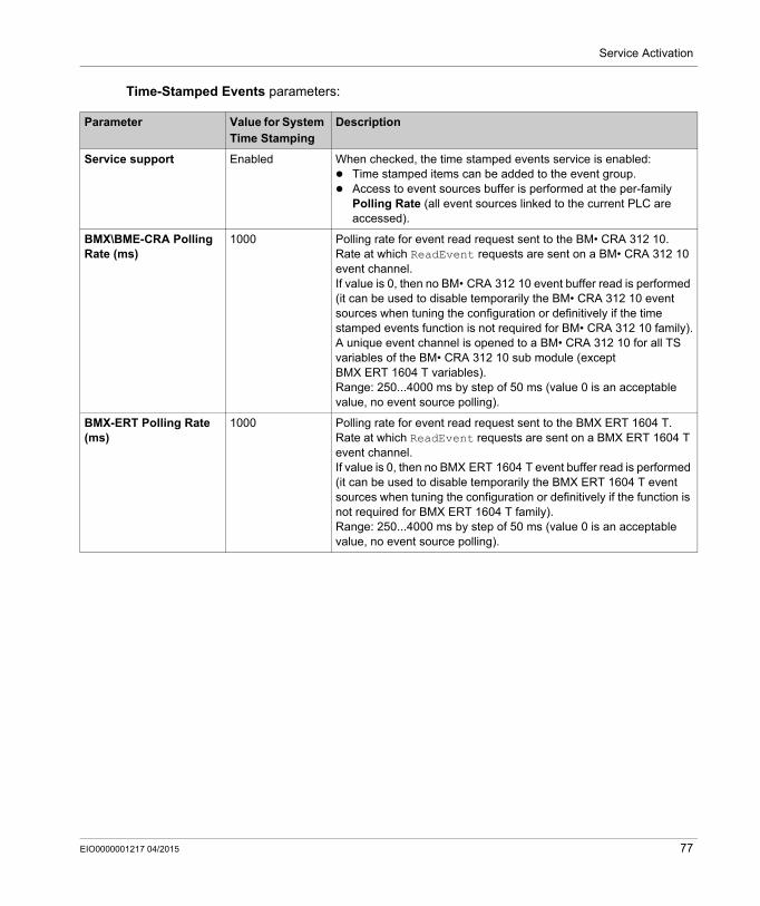
Time-Stamped Events parameters:
Parameter Value for System Time Stamping
Description
Service support Enabled When checked, the time stamped events service is enabled: Time stamped items can be added to the event group. Access to event sources buffer is performed at the per-family
Polling Rate (all event sources linked to the current PLC are accessed).
BMX\BME-CRA Polling Rate (ms)
1000 Polling rate for event read request sent to the BM• CRA 312 10.Rate at which ReadEvent requests are sent on a BM• CRA 312 10 event channel.If value is 0, then no BM• CRA 312 10 event buffer read is performed (it can be used to disable temporarily the BM• CRA 312 10 event sources when tuning the configuration or definitively if the time stamped events function is not required for BM• CRA 312 10 family).A unique event channel is opened to a BM• CRA 312 10 for all TS variables of the BM• CRA 312 10 sub module (except BMX ERT 1604 T variables).Range: 250...4000 ms by step of 50 ms (value 0 is an acceptable value, no event source polling).
BMX-ERT Polling Rate (ms)
1000 Polling rate for event read request sent to the BMX ERT 1604 T.Rate at which ReadEvent requests are sent on a BMX ERT 1604 T event channel.If value is 0, then no BMX ERT 1604 T event buffer read is performed (it can be used to disable temporarily the BMX ERT 1604 T event sources when tuning the configuration or definitively if the function is not required for BMX ERT 1604 T family).Range: 250...4000 ms by step of 50 ms (value 0 is an acceptable value, no event source polling).
EIO0000001217 04/2015 77

Service Activation
78 EIO0000001217 04/2015
System Time Stamping
Selecting Variables
EIO0000001217 04/2015
Selecting and Configuring the Variables to Time Stamp
Chapter 9Selecting and Configuring the Variables to Time Stamp
Overview
This chapter presents how to configure and activate the time stamping variables.
NOTE: All variables that need to be time stamped as well as time stamping global parameters need to be activated in Unity Pro.
What Is in This Chapter?
This chapter contains the following topics:
Topic Page
Variables Usage 80
BME P58 xxxx Variables Settings in Unity Pro 81
BMX ERT 1604 T Variables Settings in Unity Pro 82
BMx CRA 312 10 Variables Settings in Unity Pro 89
EIO0000001217 04/2015 79
Selecting Variables
Variables Usage
System Performance
Time stamping events usage has to be restricted to real needs. Each time stamped event adds additional communication to the system and thus limits the global system bandwidth.
System performance is therefore limited by intensive time stamping variables usage. Only select the variables that really need to be mapped on time stamped events.
System Limitations
System limitations (see page 53) represent the maximum physical limits allowed in the system.
80 EIO0000001217 04/2015
Selecting Variables
BME P58 xxxx Variables Settings in Unity Pro
Steps to Follow to Configure the Variables
Steps to follow in Unity Pro for the BME P58 •••• CPU:
Buffer Settings in Unity Pro
BME P58 •••• buffer behavior settings cannot be adjusted and they are preset as follows: on buffer full: The CPU stops the recording when the events buffer is full (stop the recording). on power on: New events are added to the existing events buffer if the application is the same.
NOTE: If the application is not the same, on power on the event buffer is cleared.
on stop to run: New events are added to the existing events buffer if the application is the same.
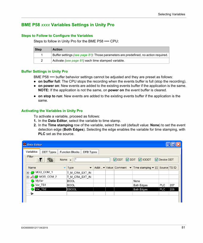
Activating the Variables in Unity Pro
To activate a variable, proceed as follows:1. In the Data Editor, select the variable to time stamp.2. In the Time stamping row of the variable, select the cell (default value: None) to set the event
detection edge (Both Edges). Selecting the edge enables the variable for time stamping, with PLC set as the source.
Step Action
1 Buffer settings (see page 81): Those parameters are predefined, no action required.
2 Activate (see page 81) each time stamped variable.
EIO0000001217 04/2015 81
Selecting Variables
BMX ERT 1604 T Variables Settings in Unity Pro
Steps to Follow to Configure the Variables
Steps to follow in Unity Pro for each BMX ERT 1604 T module:
Buffer Settings in Unity Pro
BMX ERT 1604 T buffer behavior settings cannot be adjusted and they are set as follows: on buffer full: The BMX ERT 1604 T module stops the recording when the events buffer is full
(stop the recording). on power on: New events can be added to the existing events buffer if the application is the
same.NOTE: If the application is not the same, on power on the event buffer is cleared.
on stop to run: New events are added to the existing events buffer.
Selecting the Channels in Unity Pro
In Unity Pro, to select the variables to time stamp, double-click the BMX ERT 1604 T module in the drop.
Step Action
1 Buffer settings (see page 82): Those parameters are predefined, no action required.
2 Select the channels (see page 82) to time stamp in the module.
3 Activate each time stamped variable: in a Modicon M340 PLC (local drop) (see page 84) in a Modicon X80 Ethernet RIO Drop (see page 86)
82 EIO0000001217 04/2015
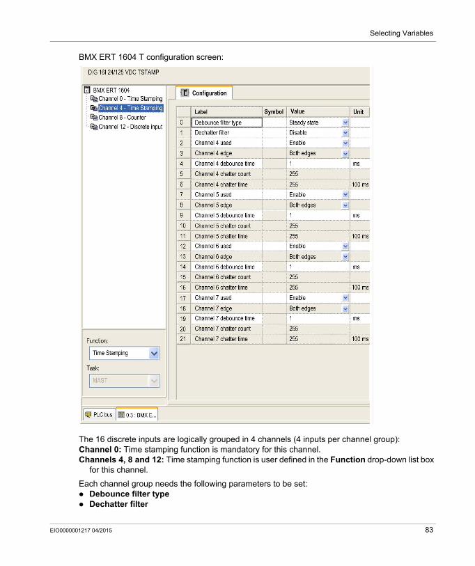
Selecting Variables
BMX ERT 1604 T configuration screen:
The 16 discrete inputs are logically grouped in 4 channels (4 inputs per channel group):Channel 0: Time stamping function is mandatory for this channel.Channels 4, 8 and 12: Time stamping function is user defined in the Function drop-down list box
for this channel.
Each channel group needs the following parameters to be set: Debounce filter type Dechatter filter
EIO0000001217 04/2015 83
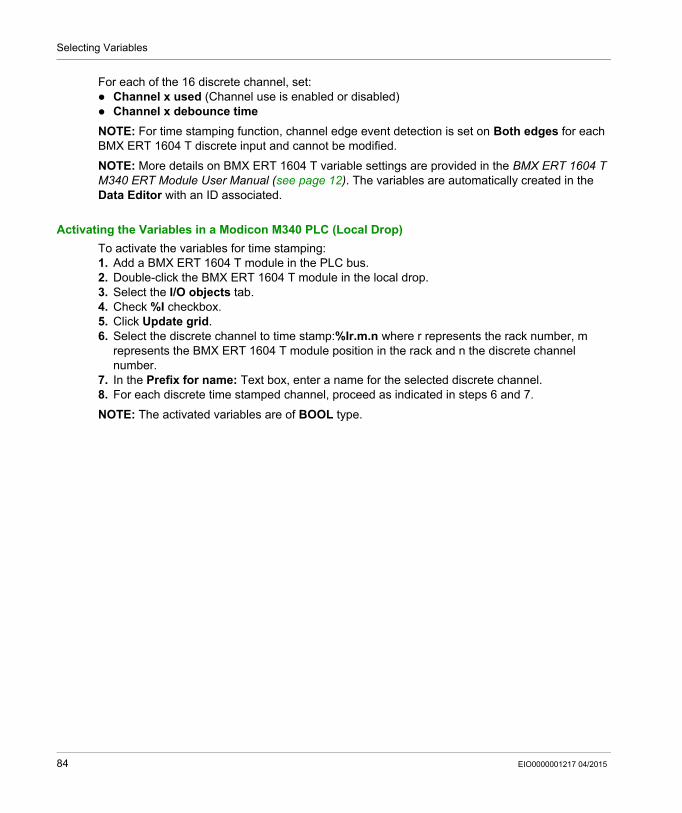
Selecting Variables
For each of the 16 discrete channel, set: Channel x used (Channel use is enabled or disabled) Channel x debounce time
NOTE: For time stamping function, channel edge event detection is set on Both edges for each BMX ERT 1604 T discrete input and cannot be modified.
NOTE: More details on BMX ERT 1604 T variable settings are provided in the BMX ERT 1604 T M340 ERT Module User Manual (see page 12). The variables are automatically created in the Data Editor with an ID associated.
Activating the Variables in a Modicon M340 PLC (Local Drop)
To activate the variables for time stamping:1. Add a BMX ERT 1604 T module in the PLC bus.2. Double-click the BMX ERT 1604 T module in the local drop.3. Select the I/O objects tab.4. Check %I checkbox.5. Click Update grid.6. Select the discrete channel to time stamp:%Ir.m.n where r represents the rack number, m
represents the BMX ERT 1604 T module position in the rack and n the discrete channel number.
7. In the Prefix for name: Text box, enter a name for the selected discrete channel.8. For each discrete time stamped channel, proceed as indicated in steps 6 and 7.
NOTE: The activated variables are of BOOL type.
84 EIO0000001217 04/2015
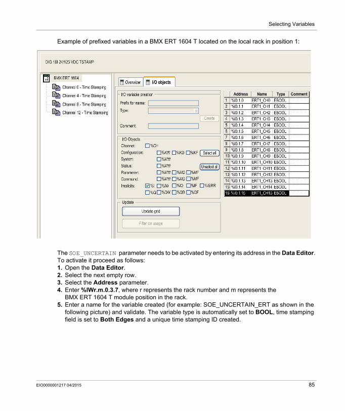
Selecting Variables
Example of prefixed variables in a BMX ERT 1604 T located on the local rack in position 1:
The SOE_UNCERTAIN parameter needs to be activated by entering its address in the Data Editor. To activate it proceed as follows:1. Open the Data Editor.2. Select the next empty row.3. Select the Address parameter.4. Enter %IWr.m.0.3.7, where r represents the rack number and m represents the
BMX ERT 1604 T module position in the rack.5. Enter a name for the variable created (for example: SOE_UNCERTAIN_ERT as shown in the
following picture) and validate. The variable type is automatically set to BOOL, time stamping field is set to Both Edges and a unique time stamping ID created.
EIO0000001217 04/2015 85
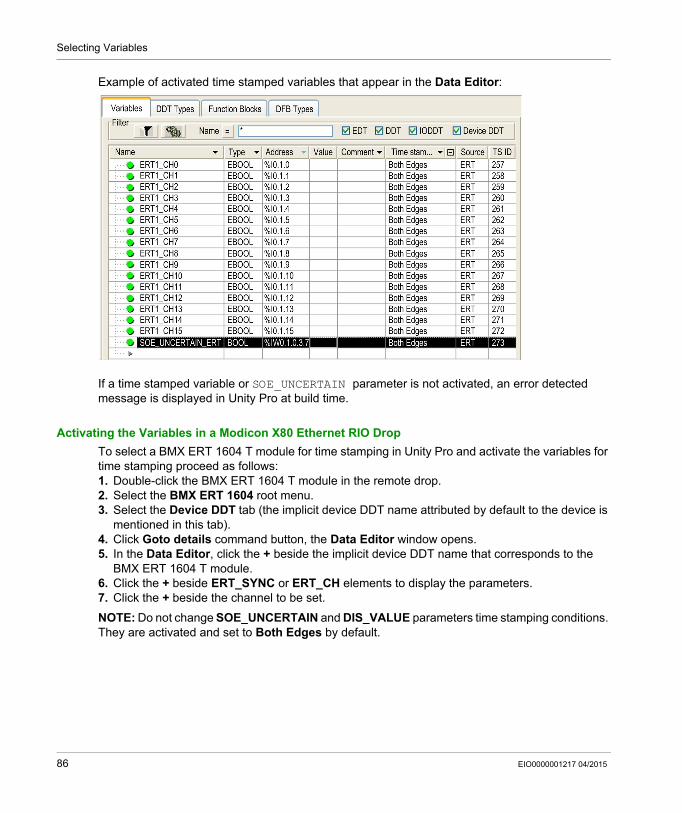
Selecting Variables
Example of activated time stamped variables that appear in the Data Editor:
If a time stamped variable or SOE_UNCERTAIN parameter is not activated, an error detected message is displayed in Unity Pro at build time.
Activating the Variables in a Modicon X80 Ethernet RIO Drop
To select a BMX ERT 1604 T module for time stamping in Unity Pro and activate the variables for time stamping proceed as follows:1. Double-click the BMX ERT 1604 T module in the remote drop.2. Select the BMX ERT 1604 root menu.3. Select the Device DDT tab (the implicit device DDT name attributed by default to the device is
mentioned in this tab).4. Click Goto details command button, the Data Editor window opens.5. In the Data Editor, click the + beside the implicit device DDT name that corresponds to the
BMX ERT 1604 T module.6. Click the + beside ERT_SYNC or ERT_CH elements to display the parameters.7. Click the + beside the channel to be set.
NOTE: Do not change SOE_UNCERTAIN and DIS_VALUE parameters time stamping conditions. They are activated and set to Both Edges by default.
86 EIO0000001217 04/2015
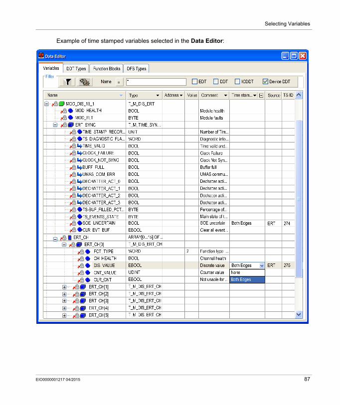
Selecting Variables
Example of time stamped variables selected in the Data Editor:
EIO0000001217 04/2015 87
Selecting Variables
Variables Mapping
For a BMX ERT 1604 T module, 2 cases are considered: The module is located in the PLC local rack: Mapping is the topological address of the
BMX ERT 1604 T input time stamped. The module is located in a Modicon X80 drop: Mapping is provided by device DDT, the I/O time
stamped module location is used (for example \2.1.0.1 means: bus 2 (RIO), drop 1, rack 0, slot 1).An alias can also be associated with a time stamped variable in device DDT.
For more details on BMX ERT 1604 T module variables, refer to BMX ERT 1604 T Software Implementation part of BMX ERT 1604 T, M340 ERT Module, User Manual (see page 12).
88 EIO0000001217 04/2015
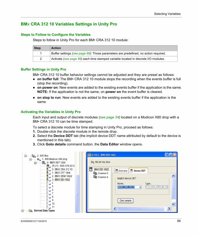
Selecting Variables
BMx CRA 312 10 Variables Settings in Unity Pro
Steps to Follow to Configure the Variables
Steps to follow in Unity Pro for each BM• CRA 312 10 module:
Buffer Settings in Unity Pro
BM• CRA 312 10 buffer behavior settings cannot be adjusted and they are preset as follows: on buffer full: The BM• CRA 312 10 module stops the recording when the events buffer is full
(stop the recording). on power on: New events are added to the existing events buffer if the application is the same.
NOTE: If the application is not the same, on power on the event buffer is cleared.
on stop to run: New events are added to the existing events buffer if the application is the same.
Activating the Variables in Unity Pro
Each input and output of discrete modules (see page 34) located on a Modicon X80 drop with a BM• CRA 312 10 can be time stamped.
To select a discrete module for time stamping in Unity Pro, proceed as follows:1. Double-click the discrete module in the remote drop.2. Select the Device DDT tab (the implicit device DDT name attributed by default to the device is
mentioned in this tab).3. Click Goto details command button, the Data Editor window opens.
Step Action
1 Buffer settings (see page 89): Those parameters are predefined, no action required.
2 Activate (see page 89) each time stamped variable located in discrete I/O modules.
EIO0000001217 04/2015 89
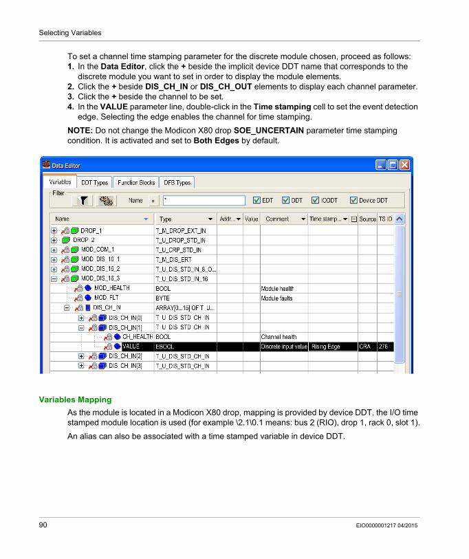
Selecting Variables
To set a channel time stamping parameter for the discrete module chosen, proceed as follows:1. In the Data Editor, click the + beside the implicit device DDT name that corresponds to the
discrete module you want to set in order to display the module elements.2. Click the + beside DIS_CH_IN or DIS_CH_OUT elements to display each channel parameter.3. Click the + beside the channel to be set.4. In the VALUE parameter line, double-click in the Time stamping cell to set the event detection
edge. Selecting the edge enables the channel for time stamping.
NOTE: Do not change the Modicon X80 drop SOE_UNCERTAIN parameter time stamping condition. It is activated and set to Both Edges by default.
Variables Mapping
As the module is located in a Modicon X80 drop, mapping is provided by device DDT, the I/O time stamped module location is used (for example \2.1\0.1 means: bus 2 (RIO), drop 1, rack 0, slot 1).
An alias can also be associated with a time stamped variable in device DDT.
90 EIO0000001217 04/2015
System Time Stamping
Selecting Communication Parameters
EIO0000001217 04/2015
Selecting the Communication Parameters
Chapter 10Selecting the Communication Parameters
Overview
This chapter describes how to set the communication parameters once the number of events detected is properly estimated.
What Is in This Chapter?
This chapter contains the following topics:
Topic Page
Capability Checks 92
OFS Communication Settings 94
EIO0000001217 04/2015 91
Selecting Communication Parameters
Capability Checks
Requirements
The normal average number of time stamped events detected per second in the installation needs to be estimated by the user in order to define the communication parameters.
Based on the normal number of events, the user sets: OFS polling rate (see page 94) OFS client alive timeout (see page 94)
OFS Performance
OFS communicates with several PLCs and devices. The assumption is that 50% of the PC resources are used by OFS and 50% are used by Vijeo Citect.
A dedicated tool (OFS TimeStamp Helper) is used to estimate the event detection capability depending on the polling rate chosen. This tool is located on the OFS installation DVD.
OFS TimeStamp Performance Helper Tool Purpose and Use
OFS TimeStamp Helper tool is intended to help you to define OFS setting parameters when it is used in a configuration with time stamping solution.
NOTE: .NET Framework 3.5 Service Pack 1 or higher is required to run OFS TimeStamp Helper.
The Configuration tab allows to configure OFS TimeStamp Helper tool. When the cursor points to a spin box with a value to be entered, Minimum and Maximum values are displayed in a dialog box. In Configuration → General specify the number of PLCs included in the installation. In Configuration → PLC Configuration : → PLC n° x specify the parameters for each PLC of
the installation.
The Results tab displays information provided by the OFS TimeStamp Helper tool. When the cursor points to a result dialog box, the value Limit is displayed in a dialog box.If the limit value is exceeded the dialog box border is displayed in red. Recommendation on normal number of events detected per second.
According to the hardware architecture and the associated OFS time stamped events polling rates, the tool provides a recommendation on the normal number of events detected per seconds that should be targeted in order to be able to manage additional temporary bursts of events stored in the buffer.
92 EIO0000001217 04/2015
Selecting Communication Parameters
This information appears in the following folders: Results → PLC Results : → PLC n° x → CPU, or BMX CRA, or BMX ERT
Number of events detected per second per CPU, or CRA, or ERTCPU: Computed polling rate in msCRA or ERT: Total number of events detected per second per PLC
Results → GeneralCPUs Total number of events detected per secondBMX-CRAs total number of events detected per second (for all PLCs)BMX-ERTs total number of events detected per second (for all PLCs)
Estimation of the time needed to read a full buffer.After a temporary burst or after a particular operating mode such as a cable disconnection between the time stamping source of events and OFS, the event buffer can become full. The tool provides an estimation of the time needed to read this event buffer and to come back to a normal situation in which the system runs with the normal number of events per second. The time to read the buffer depends on the OFS time stamped events polling rate (buffer output flow), the number of events stored in the buffer and the normal number of events per second (buffer input flow).This information appears in the following folder: Results → PLC Results : → PLC n° x → CPU, or BMX CRA, or BMX ERT
Time to read full buffer in secondNOTE: For a BMX ERT 1604 T, Time to read full buffer in second is a minimum value because the tool considers that there is 1 event in each of the 255 groups of the BMX ERT 1604 T buffer. A group is a set of 1 to 16 events detected in the same cycle. If 16 events are detected in each group, the Time to read full buffer in second value has to be multiplied by 16.
Estimation of the total OFS bandwidth (msg/sec).The tool provides an estimation of the total OFS bandwidth (msg/sec.) used to read the normal number of events per second on all PLCs and it checks that the estimated bandwidth does not exceed the maximum OFS bandwidth allocated to read events.This information appears in the following folder: Results → General
OFS bandwidth used to read events (msg/s)
Total number of time stamped I/Os in 1 PLC.This information allows to check that the maximum number of configured time stamped I/Os is not exceeded.This information appears in the following folder: Results → PLC Results : → PLC n° x
Total number of time stamped IOs on one PLC
EIO0000001217 04/2015 93
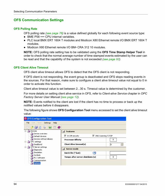
Selecting Communication Parameters
OFS Communication Settings
OFS Polling Rate
OFS polling rate (see page 76) is a value defined globally for each following event source type: BME P58 •••• CPU internal variables. PLC local BMX ERT 1604 T modules and Modicon X80 Ethernet remote I/O BMX ERT 1604 T
modules. Modicon X80 Ethernet remote I/O BM• CRA 312 10 modules.
NOTE: OFS polling rate setting has to be validated using the OFS Time Stamp Helper Tool in order to check that the normal average number of time stamped events estimated by the user can be read and that the capability of the system is not exceeded (see page 92).
OFS Client Alive Timeout
OFS client alive timeout allows OFS to detect that the OFS client is not responding.
If OFS client is not responding, the event group is deactivated and OFS stops reading events in the sources. For that reason, make sure to configure a client alive timeout value not equal to 0 in order to activate this function.
Client alive timeout value is set between 2...30 s. Timeout value is determined by the customer.
For more details on setting client alive service in OFS, refer to Client-alive Service chapter in OPC Factory Server User Manual (see page 12).
NOTE: Events notified to the client are lost if the client has no time to process or back up the notified values before it disappears.
The following figure shows OFS Configuration Tool menu accessed to set the client alive timeout value:
94 EIO0000001217 04/2015
System Time Stamping
Setting Vijeo Citect Parameters
EIO0000001217 04/2015
Setting Vijeo Citect Parameters
Chapter 11Setting Vijeo Citect Parameters
Overview
This chapter describes the parameters to configure in Vijeo Citect to visualize the sequence of events and quality parameters.
What Is in This Chapter?
This chapter contains the following topics:
Topic Page
Vijeo Citect Parameters 96
Time Quality and SOE Uncertain Sequence 100
EIO0000001217 04/2015 95
Setting Vijeo Citect Parameters
Vijeo Citect Parameters
Overview
Vijeo Citect receives time stamped variable data from OFS via OFSOPC driver and provides a display of: Time stamped data Time quality Diagnostic information
The time quality information can be viewed on the Active Alarm and SOE pages for Vijeo Citect V7.30.
Vijeo Citect minimizes the chance of time stamped data loss by replicating event data between redundant I/O server instances.
More details on Vijeo Citect configuration are provided in Vijeo Citect User Guide and Vijeo Citect Help (see page 12). More details on redundancy configuration are provided in chapter Building Redundancy Into Your System of Vijeo Citect User Guide (see page 12) or Vijeo Citect Help (see page 12), and in topic Configuring Redundancy of OFSOPC Driver html help file.
At source time stamping functionality and time quality is natively displayed from Vijeo Citect V7.30. It is supported by OFSOPC driver from version v2.05.09.001.
Variable Tag Configuration
A variable tag needs to be configured in Vijeo Citect to represent the corresponding time stamped variable in the PLC. The variable tag provides access to the current time stamped OPC item value, quality, and timestamp.
To configure a time stamped digital alarm, set the variable tag data type to DIGITAL.
More details on device communication setup and variable tag configuration is provided in the Setting up device communication and Configuring variable tags sections of OFSOPC help document.
96 EIO0000001217 04/2015
Setting Vijeo Citect Parameters
Example of variable tag configuration screen:
Time Stamped Digital Alarm and Equipment Configuration
A time stamped digital alarm need to be configured in Vijeo Citect in order to display time stamped event data on the Active Alarm or SOE page. The alarm is associated with the variable tag which receives time stamped event data.
It is recommended to add static information such as time stamped event source location in one of the 8 Custom fields available (for example BMX CRA @IP address or Ethernet connection point @IP address used to reach the BMX ERT).
The name of the equipment on which the I/O is connected to generate the event (PLC1.Breaker1 for example) can be entered in the Equipment field or directly in the equipment database with Vijeo Citect V7.30.
More details on time stamped digital alarm configuration is provided in the Time-stamped Digital Alarm Properties section of Vijeo Citect User Guide (see page 12) or Vijeo Citect Help (see page 12), and details on the equipment configuration is provided in the Using Equipment section of Vijeo Citect User Guide (see page 12) or Vijeo Citect Help (see page 12).
EIO0000001217 04/2015 97
Setting Vijeo Citect Parameters
Example of time stamped digital alarm configuration screen:
98 EIO0000001217 04/2015
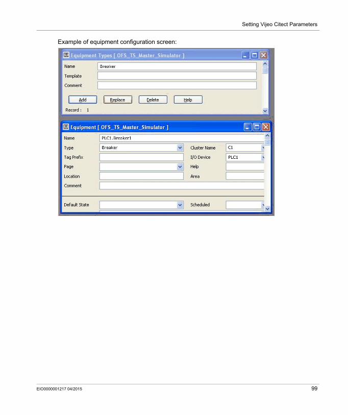
Setting Vijeo Citect Parameters
Example of equipment configuration screen:
EIO0000001217 04/2015 99
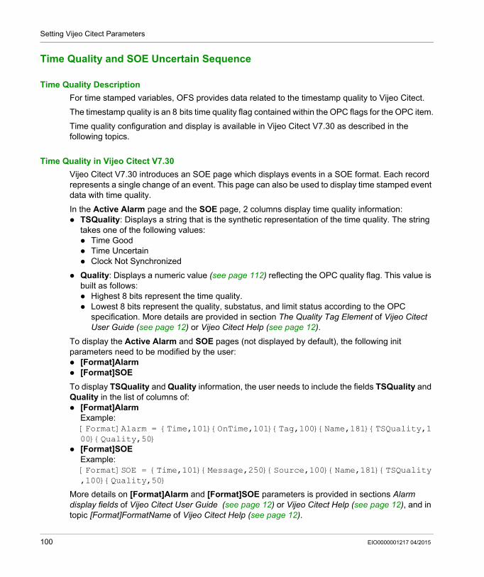
Setting Vijeo Citect Parameters
Time Quality and SOE Uncertain Sequence
Time Quality Description
For time stamped variables, OFS provides data related to the timestamp quality to Vijeo Citect.
The timestamp quality is an 8 bits time quality flag contained within the OPC flags for the OPC item.
Time quality configuration and display is available in Vijeo Citect V7.30 as described in the following topics.
Time Quality in Vijeo Citect V7.30
Vijeo Citect V7.30 introduces an SOE page which displays events in a SOE format. Each record represents a single change of an event. This page can also be used to display time stamped event data with time quality.
In the Active Alarm page and the SOE page, 2 columns display time quality information: TSQuality: Displays a string that is the synthetic representation of the time quality. The string
takes one of the following values: Time Good Time Uncertain Clock Not Synchronized
Quality: Displays a numeric value (see page 112) reflecting the OPC quality flag. This value is built as follows: Highest 8 bits represent the time quality. Lowest 8 bits represent the quality, substatus, and limit status according to the OPC
specification. More details are provided in section The Quality Tag Element of Vijeo Citect User Guide (see page 12) or Vijeo Citect Help (see page 12).
To display the Active Alarm and SOE pages (not displayed by default), the following init parameters need to be modified by the user: [Format]Alarm [Format]SOE
To display TSQuality and Quality information, the user needs to include the fields TSQuality and Quality in the list of columns of: [Format]Alarm
Example: [Format]Alarm = {Time,101}{OnTime,101}{Tag,100}{Name,181}{TSQuality,100}{Quality,50}
[Format]SOEExample: [Format]SOE = {Time,101}{Message,250}{Source,100}{Name,181}{TSQuality,100}{Quality,50}
More details on [Format]Alarm and [Format]SOE parameters is provided in sections Alarm display fields of Vijeo Citect User Guide (see page 12) or Vijeo Citect Help (see page 12), and in topic [Format]FormatName of Vijeo Citect Help (see page 12).
100 EIO0000001217 04/2015
Setting Vijeo Citect Parameters
Configure an Alarm to Display SOE Uncertain Sequence
To display the uncertain SOE sequence (sequence during which some events may be lost), each event source needs to be configured as follows: A variable tag is associated (see page 96) to the source SOE uncertain variable. A time stamped digital alarm is configured (see page 97) for each variable tag previously
associated.
The SOE uncertain variable address depends on the time stamping module type and its location: BME P58 •••• CPU. The variable needs to be created by the user (see page 81) in Unity Pro and
mapped on %SW73.7 system word (SOE_UNCERTAIN). BM• CRA 312 10 module in a Modicon X80 Ethernet RIO drop: The variable is mapped on the
SOE_UNCERTAIN field of the BM• CRA 312 10 Device DDT. The Device DDT variable is automatically created (see page 89) in Unity Pro, and it has a T_M_DROP_EXT_IN type. The variable is named SOE_UNCERTAIN.
BMX ERT 1604 T module in a Modicon X80 Ethernet RIO drop: The variable is mapped on the SOE_UNCERTAIN field of the BMX ERT 1604 T Device DDT. The Device DDT variable is automatically created (see page 86) in Unity Pro, and it has a T_M_DIS_ERT type. The variable is named ERT_SYNC.SOE_UNCERTAIN.
BMX ERT 1604 T module in a Modicon M340 local drop: The variable needs to be created by the user (see page 84) in Unity Pro and mapped on %IW0.n.0.3.7 (where n represents the module position in the rack).
Configure an Alarm to Display TS Event Source Disconnection
To display the status of the connection with the event source, associate 1 digital alarm per source with a specific item: <direct_address>!#PlcQualStatus where <direct_address> is the address of the source. For more details, refer to Specific Items → Description topic in OPC Factory Server User Manual (see page 12).
EIO0000001217 04/2015 101

Setting Vijeo Citect Parameters
102 EIO0000001217 04/2015
System Time Stamping
Commissioning and Operation
EIO0000001217 04/2015
Commissioning and Operation Phases
Part IVCommissioning and Operation Phases
Introduction
This part presents the time stamping diagnostic, the behavior on operating modes and time synchronization.
What Is in This Part?
This part contains the following chapters:
Chapter Chapter Name Page
12 Diagnostic 105
13 Behavior on Operating Modes 119
14 Behavior on Time Synchronization 133
EIO0000001217 04/2015 103

Commissioning and Operation
104 EIO0000001217 04/2015
System Time Stamping
Diagnostic
EIO0000001217 04/2015
Diagnostic
Chapter 12Diagnostic
Overview
This chapter describes the available diagnostic views, the diagnostic information provided by the system and the components diagnostic.
What Is in This Chapter?
This chapter contains the following topics:
Topic Page
Introduction 106
PLC View 107
OFS View 109
Vijeo Citect View 111
Hardware Diagnostic 114
EIO0000001217 04/2015 105
Diagnostic
Introduction
Diagnostic Data
Diagnostic data provide information on: Quality of the time stamping for each event. Time and buffers management. Communication between each time stamping source and client.
Diagnostic information is displayed on: Vijeo Citect OFS PLC variable viewers Time stamping source module (hardware)
Diagnostic Sources
At source time stamping diagnostic information is provided by: Time stamping event sources. OFS software.
Diagnostic Data Availability
The following table describes the diagnostic data access mode and presentation:
Vijeo Citect Settings
It is strongly recommended to set time stamping diagnostic parameters in Vijeo Citect (see page 111).
Diagnostic Data Source Diagnostic Data Presentation
Time stamping event sources Buffer diagnostic Viewers of PLC variables: Device DDT or IODDT (SCADA, Unity Pro...).Time valid, synchronized
TS Events service state
I/O Channel error
SOE Uncertain (1.) SCADA alarm viewer or SOE viewer.
Time Quality
I/O channel error
OFS Event service communication
Network Info window in the Devices tree-view.
Connection health status SCADA alarm viewer or SOE viewer or diagnostic animation page.
1. Variable tag needs to be created by the user.
106 EIO0000001217 04/2015
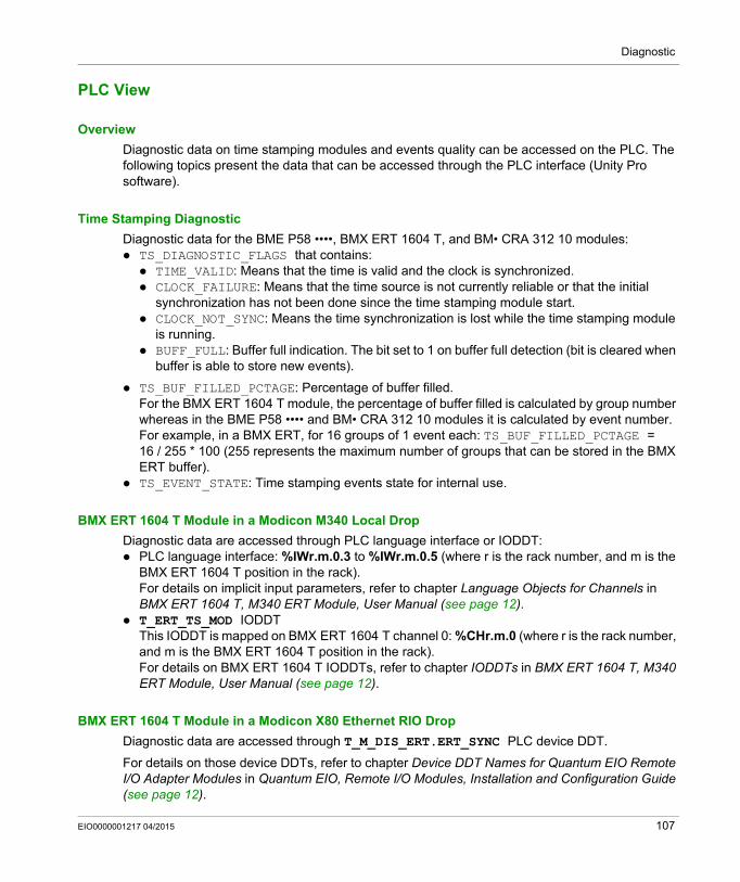
Diagnostic
PLC View
Overview
Diagnostic data on time stamping modules and events quality can be accessed on the PLC. The following topics present the data that can be accessed through the PLC interface (Unity Pro software).
Time Stamping Diagnostic
Diagnostic data for the BME P58 ••••, BMX ERT 1604 T, and BM• CRA 312 10 modules: TS_DIAGNOSTIC_FLAGS that contains: TIME_VALID: Means that the time is valid and the clock is synchronized. CLOCK_FAILURE: Means that the time source is not currently reliable or that the initial
synchronization has not been done since the time stamping module start. CLOCK_NOT_SYNC: Means the time synchronization is lost while the time stamping module
is running. BUFF_FULL: Buffer full indication. The bit set to 1 on buffer full detection (bit is cleared when
buffer is able to store new events).
TS_BUF_FILLED_PCTAGE: Percentage of buffer filled.For the BMX ERT 1604 T module, the percentage of buffer filled is calculated by group number whereas in the BME P58 •••• and BM• CRA 312 10 modules it is calculated by event number. For example, in a BMX ERT, for 16 groups of 1 event each: TS_BUF_FILLED_PCTAGE = 16 / 255 * 100 (255 represents the maximum number of groups that can be stored in the BMX ERT buffer).
TS_EVENT_STATE: Time stamping events state for internal use.
BMX ERT 1604 T Module in a Modicon M340 Local Drop
Diagnostic data are accessed through PLC language interface or IODDT: PLC language interface: %IWr.m.0.3 to %IWr.m.0.5 (where r is the rack number, and m is the
BMX ERT 1604 T position in the rack).For details on implicit input parameters, refer to chapter Language Objects for Channels in BMX ERT 1604 T, M340 ERT Module, User Manual (see page 12).
T_ERT_TS_MOD IODDTThis IODDT is mapped on BMX ERT 1604 T channel 0: %CHr.m.0 (where r is the rack number, and m is the BMX ERT 1604 T position in the rack).For details on BMX ERT 1604 T IODDTs, refer to chapter IODDTs in BMX ERT 1604 T, M340 ERT Module, User Manual (see page 12).
BMX ERT 1604 T Module in a Modicon X80 Ethernet RIO Drop
Diagnostic data are accessed through T_M_DIS_ERT.ERT_SYNC PLC device DDT.
For details on those device DDTs, refer to chapter Device DDT Names for Quantum EIO Remote I/O Adapter Modules in Quantum EIO, Remote I/O Modules, Installation and Configuration Guide (see page 12).
EIO0000001217 04/2015 107
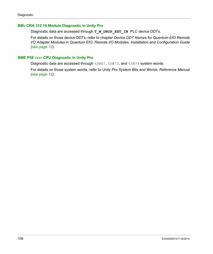
Diagnostic
BMx CRA 312 10 Module Diagnostic in Unity Pro
Diagnostic data are accessed through T_M_DROP_EXT_IN PLC device DDTs.
For details on those device DDTs, refer to chapter Device DDT Names for Quantum EIO Remote I/O Adapter Modules in Quantum EIO, Remote I/O Modules, Installation and Configuration Guide (see page 12).
BME P58 xxxx CPU Diagnostic in Unity Pro
Diagnostic data are accessed through %SW67, %SW73, and %SW74 system words.
For details on those system words, refer to Unity Pro System Bits and Words, Reference Manual (see page 12).
108 EIO0000001217 04/2015
Diagnostic
OFS View
Introduction
OFS provides diagnostic data on connection status of the event sources and buffer level.
Items for Connection Diagnostic Between OFS and Devices
To diagnose the connection status with the time stamping event sources, 2 items of VT_I2 type (activated in a standard OPC group) are available and can be displayed on the SCADA (Vijeo Citect View for example): #PLCQualStatus #PLCQualStatus2
NOTE: Those 2 items have the same feature, but it is recommended to use #PLCQualStatus item because: It optimizes the communication when used in groups with different periods. It automatically uses #PLCQualStatus2 item on devices that are not the PLC.
Those items can return one of the following values:QUAL_BAD + QUAL_COMM_FAILURE (value 0018 hex): Device is INCONSISTENT
(SymbolFile differs from PLC application).QUAL_BAD + QUAL_DEVICE_FAILURE (value 000C hex): No communication with the device
since DEVICE_TO milliseconds.QUAL_BAD (value 0000 hex): Device is MISSING or UNKNOWN.QUAL_GOOD (value 00C0 hex): Communication with the device is correct.QUAL_UNCERTAIN (value 0040 hex): No communication with the device since less than
DEVICE_TO milliseconds.
For more details on the time stamping event sources diagnostic items, syntax and content, refer to sections Specific Items and Time Stamped Events Configuration in OPC Factory Server User Manual (see page 12).
EIO0000001217 04/2015 109
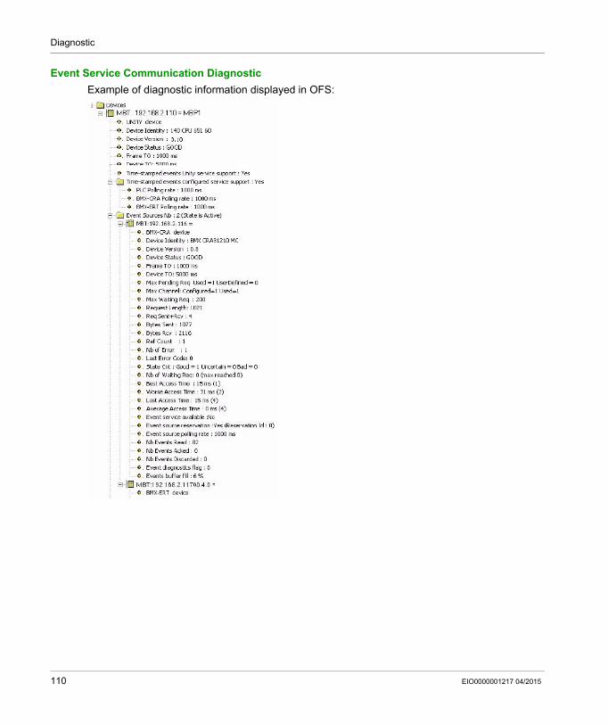
Diagnostic
Event Service Communication Diagnostic
Example of diagnostic information displayed in OFS:
110 EIO0000001217 04/2015
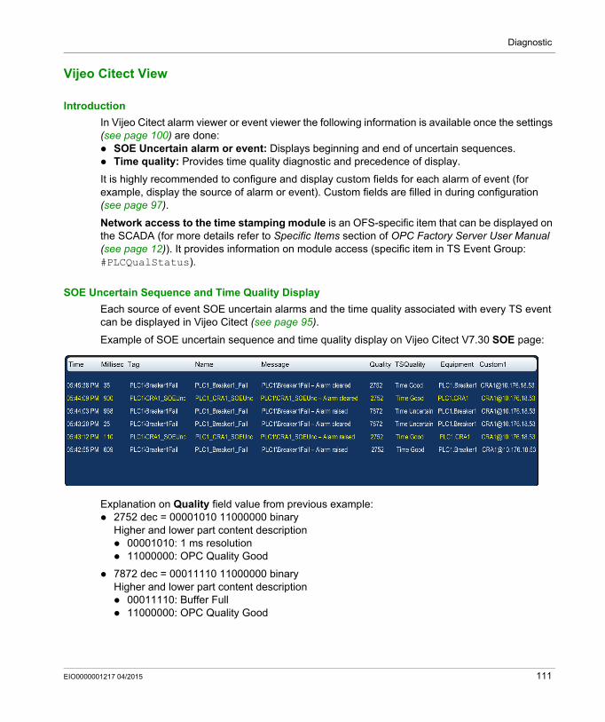
Diagnostic
Vijeo Citect View
Introduction
In Vijeo Citect alarm viewer or event viewer the following information is available once the settings (see page 100) are done: SOE Uncertain alarm or event: Displays beginning and end of uncertain sequences. Time quality: Provides time quality diagnostic and precedence of display.
It is highly recommended to configure and display custom fields for each alarm of event (for example, display the source of alarm or event). Custom fields are filled in during configuration (see page 97).
Network access to the time stamping module is an OFS-specific item that can be displayed on the SCADA (for more details refer to Specific Items section of OPC Factory Server User Manual (see page 12)). It provides information on module access (specific item in TS Event Group: #PLCQualStatus).
SOE Uncertain Sequence and Time Quality Display
Each source of event SOE uncertain alarms and the time quality associated with every TS event can be displayed in Vijeo Citect (see page 95).
Example of SOE uncertain sequence and time quality display on Vijeo Citect V7.30 SOE page:
Explanation on Quality field value from previous example: 2752 dec = 00001010 11000000 binary
Higher and lower part content description 00001010: 1 ms resolution 11000000: OPC Quality Good
7872 dec = 00011110 11000000 binaryHigher and lower part content description 00011110: Buffer Full 11000000: OPC Quality Good
EIO0000001217 04/2015 111
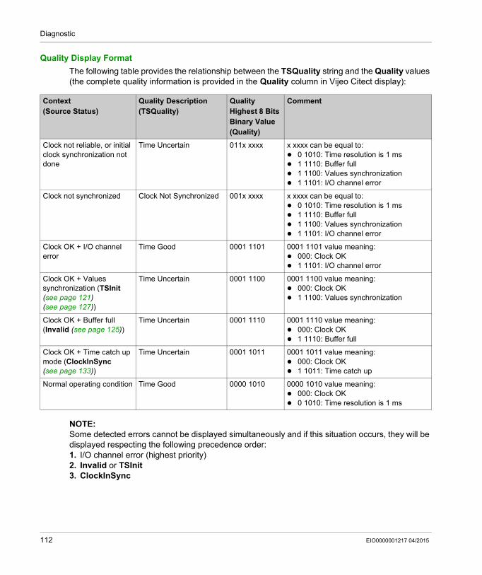
Diagnostic
Quality Display Format
The following table provides the relationship between the TSQuality string and the Quality values (the complete quality information is provided in the Quality column in Vijeo Citect display):
NOTE: Some detected errors cannot be displayed simultaneously and if this situation occurs, they will be displayed respecting the following precedence order:1. I/O channel error (highest priority)2. Invalid or TSInit3. ClockInSync
Context (Source Status)
Quality Description(TSQuality)
Quality Highest 8 Bits Binary Value(Quality)
Comment
Clock not reliable, or initial clock synchronization not done
Time Uncertain 011x xxxx x xxxx can be equal to: 0 1010: Time resolution is 1 ms 1 1110: Buffer full 1 1100: Values synchronization 1 1101: I/O channel error
Clock not synchronized Clock Not Synchronized 001x xxxx x xxxx can be equal to: 0 1010: Time resolution is 1 ms 1 1110: Buffer full 1 1100: Values synchronization 1 1101: I/O channel error
Clock OK + I/O channel error
Time Good 0001 1101 0001 1101 value meaning: 000: Clock OK 1 1101: I/O channel error
Clock OK + Values synchronization (TSInit (see page 121) (see page 127))
Time Uncertain 0001 1100 0001 1100 value meaning: 000: Clock OK 1 1100: Values synchronization
Clock OK + Buffer full (Invalid (see page 125))
Time Uncertain 0001 1110 0001 1110 value meaning: 000: Clock OK 1 1110: Buffer full
Clock OK + Time catch up mode (ClockInSync (see page 133))
Time Uncertain 0001 1011 0001 1011 value meaning: 000: Clock OK 1 1011: Time catch up
Normal operating condition Time Good 0000 1010 0000 1010 value meaning: 000: Clock OK 0 1010: Time resolution is 1 ms
112 EIO0000001217 04/2015
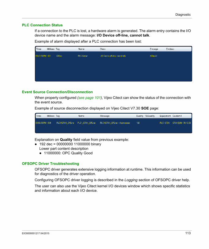
Diagnostic
PLC Connection Status
If a connection to the PLC is lost, a hardware alarm is generated. The alarm entry contains the I/O device name and the alarm message: I/O Device off-line, cannot talk.
Example of alarm displayed after a PLC connection has been lost:
Event Source Connection/Disconnection
When properly configured (see page 101), Vijeo Citect can show the status of the connection with the event source.
Example of source disconnection displayed on Vijeo Citect V7.30 SOE page:
Explanation on Quality field value from previous example: 192 dec = 00000000 11000000 binary
Lower part content description 11000000: OPC Quality Good
OFSOPC Driver Troubleshooting
OFSOPC driver generates extensive logging information at runtime. This information can be used for diagnostics of the driver operation.
Configuring OFSOPC driver logging is described in the Logging section of OFSOPC driver help.
The user can also use the Vijeo Citect kernel I/O devices window which shows specific statistics and information about each I/O device.
EIO0000001217 04/2015 113
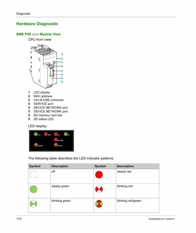
Diagnostic
Hardware Diagnostic
BME P58 xxxx Module View
CPU front view:
1 LED display2 MAC address3 mini-B USB connector4 SERVICE port5 DEVICE NETWORK port5 DEVICE NETWORK port5 SD memory card slot5 SD status LED
LED display:
The following table describes the LED indicator patterns:
Symbol Description Symbol Description
off steady red
steady green blinking red
blinking green blinking red/green
114 EIO0000001217 04/2015
Diagnostic
The following table describes the LED display activity meaning for diagnostic purpose:
Condition CPU State
RUN ERR I/O ETH MS ETH NS
power on Autotest
not configured(before getting a valid IP address or configuration is invalid)
NOCONF any pattern
configured Stop • off: no error detected• steady red: error detected in a module or a channel
• off: invalid IP address• steady red: duplicate IP address• blinking green: valid IP address but no EtherNet/IP connection• steady green: EtherNet/IP connection established
RUN
recoverable detected error
HALT any pattern • steady red: duplicate IP address• blinking red: At least one exclusive owner CIP connection (for which the BME NOC 03•1 is the originator) is timed out. The LED blinks until the connection is reestablished or the module is reset.
unrecoverable detected error
–
power off –
EIO0000001217 04/2015 115
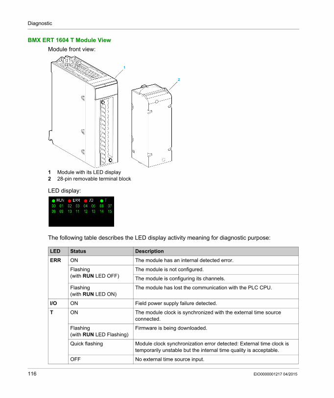
Diagnostic
BMX ERT 1604 T Module View
Module front view:
1 Module with its LED display2 28-pin removable terminal block
LED display:
The following table describes the LED display activity meaning for diagnostic purpose:
LED Status Description
ERR ON The module has an internal detected error.
Flashing(with RUN LED OFF)
The module is not configured.
The module is configuring its channels.
Flashing(with RUN LED ON)
The module has lost the communication with the PLC CPU.
I/O ON Field power supply failure detected.
T ON The module clock is synchronized with the external time source connected.
Flashing(with RUN LED Flashing)
Firmware is being downloaded.
Quick flashing Module clock synchronization error detected: External time clock is temporarily unstable but the internal time quality is acceptable.
OFF No external time source input.
116 EIO0000001217 04/2015
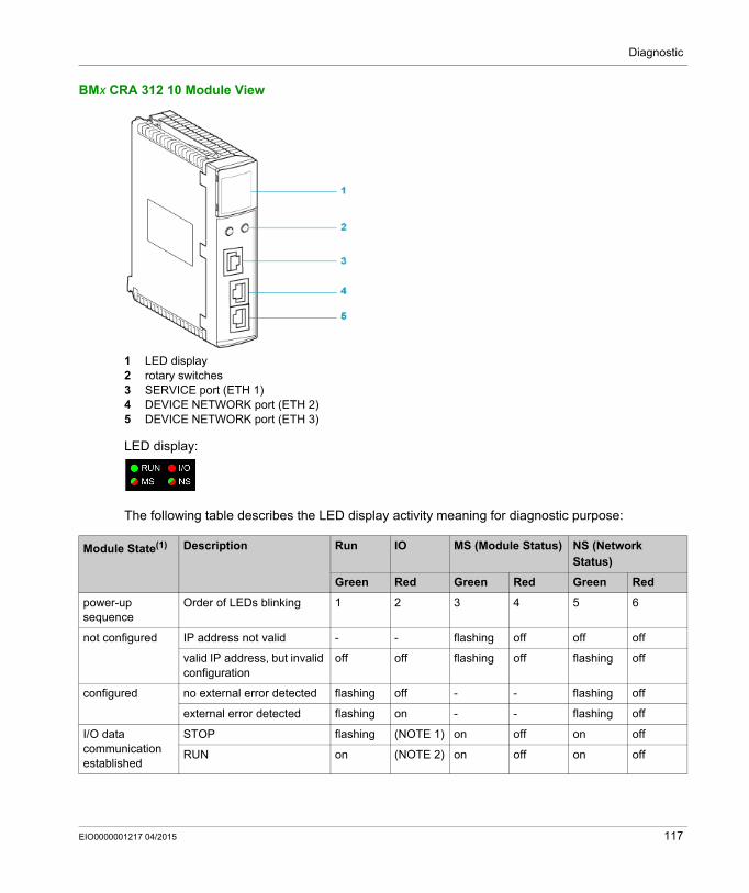
Diagnostic
BMx CRA 312 10 Module View
1 LED display2 rotary switches3 SERVICE port (ETH 1)4 DEVICE NETWORK port (ETH 2)5 DEVICE NETWORK port (ETH 3)
LED display:
The following table describes the LED display activity meaning for diagnostic purpose:
Module State(1) Description Run IO MS (Module Status) NS (Network Status)
Green Red Green Red Green Red
power-up sequence
Order of LEDs blinking 1 2 3 4 5 6
not configured IP address not valid - - flashing off off off
valid IP address, but invalid configuration
off off flashing off flashing off
configured no external error detected flashing off - - flashing off
external error detected flashing on - - flashing off
I/O data communication established
STOP flashing (NOTE 1) on off on off
RUN on (NOTE 2) on off on off
EIO0000001217 04/2015 117
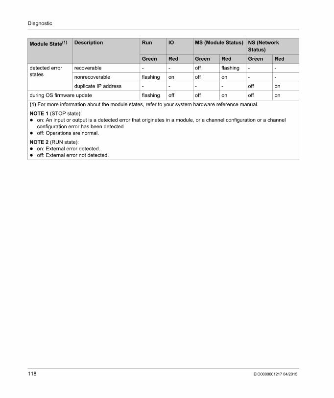
Diagnostic
detected error states
recoverable - - off flashing - -
nonrecoverable flashing on off on - -
duplicate IP address - - - - off on
during OS firmware update flashing off off on off on
(1) For more information about the module states, refer to your system hardware reference manual.
NOTE 1 (STOP state): on: An input or output is a detected error that originates in a module, or a channel configuration or a channel
configuration error has been detected. off: Operations are normal.
NOTE 2 (RUN state): on: External error detected. off: External error not detected.
Module State(1) Description Run IO MS (Module Status) NS (Network Status)
Green Red Green Red Green Red
118 EIO0000001217 04/2015
System Time Stamping
Behavior on Operating Modes
EIO0000001217 04/2015
Behavior on Operating Modes
Chapter 13Behavior on Operating Modes
Overview
This chapter describes the system behavior during different operating modes.
The last topic of this chapter is dedicated to various specific operating modes that generate a simple behavior.
NOTE: In the following chapters, the behavior is described through tables showing events, time stamps, and time quality sequences. The following list presents some of the fields shown in tables to describe the SOE sequences and the corresponding fields in Vijeo Citect SOE page (see page 111): Event: Data available in Tag, Name, and Message fields in Vijeo Citect SOE display. Timestamp: Data available in Date and Time fields in Vijeo Citect SOE display. TimeQuality attribute: Data available in the highest 8 bits of Quality field in Vijeo Citect SOE
display (see page 112).
What Is in This Chapter?
This chapter contains the following topics:
Topic Page
Operating Modes 120
Initial Start After the Application Download and First Start with Connection of the SCADA Server 121
Power Down/Up of a Time Stamping Module 123
Module Internal Event Buffer Full 125
Restart of the SCADA Server 127
Specific Operating Modes 129
EIO0000001217 04/2015 119
Behavior on Operating Modes
Operating Modes
Overview
Time stamped variable value consistency between the process and the SCADA is a key point in system time stamping solution. To manage that consistency, in addition to the time stamped transitions flow (regular events flow), the system time stamping solution manages the report of process values to the SCADA system even when the system is facing operating modes that differ from the normal operating conditions.
Operating modes that differ from the normal operating conditions: Reset and restart of the time stamping source module. Too many events in a source of events (buffer full). Reset and restart of the SCADA server.
Reset and Restart
Immediately after a restart of the time stamping source module or the relevant SCADA servers, the process values are provided to the SCADA client in order to have value consistency.
The process value flow is then provided in addition to the event data flow with respect to time stamping order.
The SCADA server is informed of process value transmission with a specific value: QualityHighByte = TSInit (see page 112).
Source of Events Module Internal Buffer Full
A time stamping source module internal buffer should not be full in normal operating conditions, but it can become full in case of disconnection between the module and the SCADA servers for example.
The system time stamping solution can generate non-accurate process values transitions between the buffer full detection and the time when a percentage of the buffer is free again. The SCADA server is informed of non-accurate process values transitions with a specific value: QualityHighByte = Invalid (see page 112).
The buffer threshold (the value cannot be modified) below which the time stamping module can time stamp events is: 50% of buffer full for the BME P58 •••• 70% of buffer full for the BMX ERT 1604 T 80% of buffer full for the BM• CRA 312 10
SOE Uncertain Event
In case of reset and restart or buffer full, the event detection is frozen and some events may be lost. Time stamped SOE uncertain events are sent to inform the SCADA server of the beginning and end of an uncertain sequence of events. SOE_UNCERTAIN values: SOE_UNCERTAIN = 1: Events might be lost in the following sequence of events. SOE_UNCERTAIN = 0: No event lost in the following sequence of events.
120 EIO0000001217 04/2015
Behavior on Operating Modes
Initial Start After the Application Download and First Start with Connection of the SCADA Server
Initial Start Sequence
NOTE: In order for the modules to start to time stamp, the SCADA server has to be started and connected, and the communication between the SCADA server and the modules has to be initialized.
Once the application download is completed, the system starts following this sequence:1. The time stamping modules get their configuration from the PLC.2. The time stamping modules synchronize their internal time with the time reference
(see page 62).3. The time stamping modules start to detect discrete value changes once the SCADA server is
started and connected.4. An initial start SOE sequence takes place as described in the following topic.
Initial Start SOE Sequence
Initial start SOE sequence description: Signalization of the beginning of an uncertain sequence of events (see following table,
sequence number 1). Storage of the values of the time stamping module inputs and outputs with
TimeQuality = ClockFailure and ClockNotSynchronized until the internal time is synchronized (see following table, sequences number 2 and 3).
Storage of the other values of the time stamping module inputs and outputs with TimeQuality = TSInit after time synchronization (see following table, sequences number 4 and 5).
Signalization of the end of the uncertain sequence of events (see following table, sequence number 6).
Normal time stamping after start of the SCADA server (see following table, sequences number 7 and 8).
Signalization of a new SOE_UNCERTAIN sequence due to the start of the SCADA server (see following table, sequences number 9 to 14).
EIO0000001217 04/2015 121
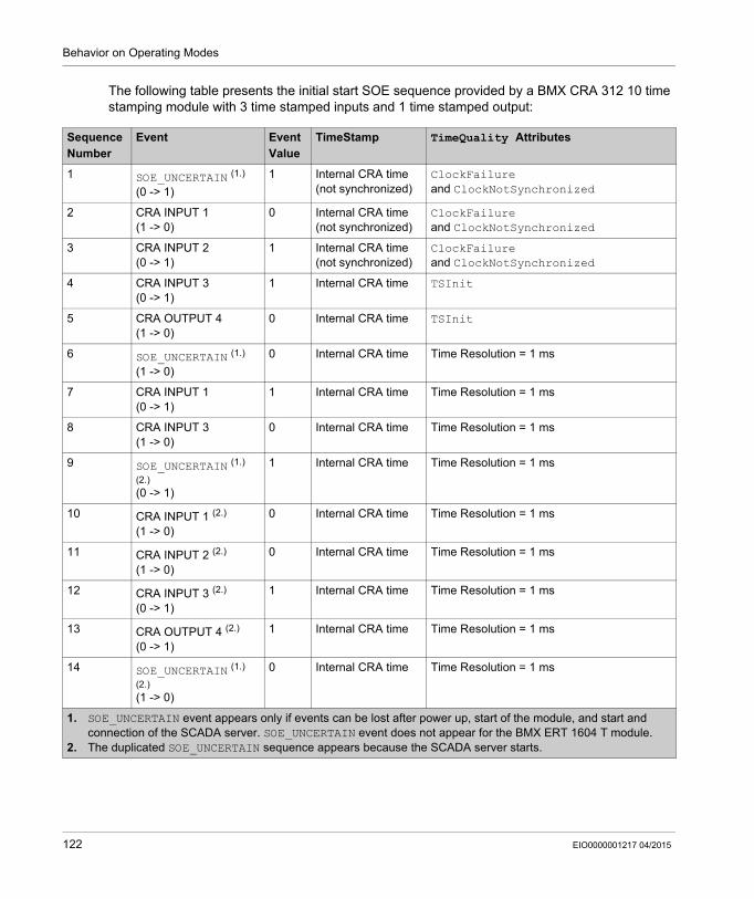
Behavior on Operating Modes
The following table presents the initial start SOE sequence provided by a BMX CRA 312 10 time stamping module with 3 time stamped inputs and 1 time stamped output:
Sequence Number
Event Event Value
TimeStamp TimeQuality Attributes
1 SOE_UNCERTAIN (1.)
(0 -> 1)
1 Internal CRA time(not synchronized)
ClockFailureand ClockNotSynchronized
2 CRA INPUT 1(1 -> 0)
0 Internal CRA time(not synchronized)
ClockFailureand ClockNotSynchronized
3 CRA INPUT 2(0 -> 1)
1 Internal CRA time(not synchronized)
ClockFailureand ClockNotSynchronized
4 CRA INPUT 3(0 -> 1)
1 Internal CRA time TSInit
5 CRA OUTPUT 4(1 -> 0)
0 Internal CRA time TSInit
6 SOE_UNCERTAIN (1.)
(1 -> 0)
0 Internal CRA time Time Resolution = 1 ms
7 CRA INPUT 1(0 -> 1)
1 Internal CRA time Time Resolution = 1 ms
8 CRA INPUT 3(1 -> 0)
0 Internal CRA time Time Resolution = 1 ms
9 SOE_UNCERTAIN (1.) (2.)
(0 -> 1)
1 Internal CRA time Time Resolution = 1 ms
10 CRA INPUT 1 (2.)
(1 -> 0)
0 Internal CRA time Time Resolution = 1 ms
11 CRA INPUT 2 (2.)
(1 -> 0)
0 Internal CRA time Time Resolution = 1 ms
12 CRA INPUT 3 (2.)
(0 -> 1)
1 Internal CRA time Time Resolution = 1 ms
13 CRA OUTPUT 4 (2.)
(0 -> 1)
1 Internal CRA time Time Resolution = 1 ms
14 SOE_UNCERTAIN (1.) (2.)
(1 -> 0)
0 Internal CRA time Time Resolution = 1 ms
1. SOE_UNCERTAIN event appears only if events can be lost after power up, start of the module, and start and connection of the SCADA server. SOE_UNCERTAIN event does not appear for the BMX ERT 1604 T module.
2. The duplicated SOE_UNCERTAIN sequence appears because the SCADA server starts.
122 EIO0000001217 04/2015
Behavior on Operating Modes
Power Down/Up of a Time Stamping Module
Power Down/Up of the Time Stamping Module
NOTE: In order for the modules to start to time stamp, the SCADA server has to be started and connected, and the communication between the SCADA server and the modules has to be initialized.
Power down/up operating mode is assumed to occur while time stamping module is time stamping events and the SCADA system is running.
The time stamping module power down is detected by the SCADA system through a specific item: #PLCQualStatus (see page 109). #PLCQualStatus = QUAL_DEVICE_FAILURE indicates that the module is not operational. In the following example table, the device failure detection is signaled in sequence number 4.
SOE Sequence on Power Down/Up of the Time Stamping Module
Sequence followed on time stamping module power up (after a power down): The events stored in the module buffer before power down (and not read in the buffer) are
available for the SCADA system (events from sequence number 1 to 3 in the following table). Signalization of time stamping module power down and power up (see following table,
sequences number 4 and 5). The rest of the sequence is the same as sequences number 1 to 6 in the initial start SOE
sequence (see page 123) (see following table, sequences number 6 to 13).
EIO0000001217 04/2015 123
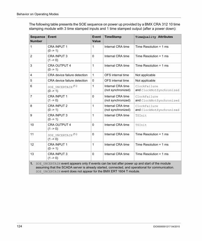
Behavior on Operating Modes
The following table presents the SOE sequence on power up provided by a BMX CRA 312 10 time stamping module with 3 time stamped inputs and 1 time stamped output (after a power down):
Sequence Number
Event Event Value
TimeStamp TimeQuality Attributes
1 CRA INPUT 1(0 -> 1)
1 Internal CRA time Time Resolution = 1 ms
2 CRA INPUT 3(1 -> 0)
0 Internal CRA time Time Resolution = 1 ms
3 CRA OUTPUT 4(0 -> 1)
1 Internal CRA time Time Resolution = 1 ms
4 CRA device failure detection 1 OFS internal time Not applicable
5 CRA device failure detection 0 OFS internal time Not applicable
6 SOE_UNCERTAIN (1.)
(0 -> 1)
1 Internal CRA time(not synchronized)
ClockFailureand ClockNotSynchronized
7 CRA INPUT 1(1 -> 0)
0 Internal CRA time(not synchronized)
ClockFailureand ClockNotSynchronized
8 CRA INPUT 2(0 -> 1)
1 Internal CRA time(not synchronized)
ClockFailureand ClockNotSynchronized
9 CRA INPUT 3(0 -> 1)
1 Internal CRA time TSInit
10 CRA OUTPUT 4(1 -> 0)
0 Internal CRA time TSInit
11 SOE_UNCERTAIN (1.)
(1 -> 0)
0 Internal CRA time Time Resolution = 1 ms
12 CRA INPUT 1(0 -> 1)
1 Internal CRA time Time Resolution = 1 ms
13 CRA INPUT 3(1 -> 0)
0 Internal CRA time Time Resolution = 1 ms
1. SOE_UNCERTAIN event appears only if events can be lost after power up and start of the module assuming that the SCADA server is already started, connected, and operational for communication. SOE_UNCERTAIN event does not appear for the BMX ERT 1604 T module.
124 EIO0000001217 04/2015
Behavior on Operating Modes
Module Internal Event Buffer Full
Time Stamping Module Internal Buffer Full
A time stamping module internal event buffer should not be full in normal case, but it can become full in case of disconnection between the module and the SCADA system for example.
A buffer full is diagnosed from the PLC via BUFF_FULL parameters in Device DDT, or IODDT, or system word, or TS_BUF_FILLED_PCTAGE parameter. On a BME P58 •••• CPU, TS_BUF_FILLED_PCTAGE parameter is located on %SW74.8...%SW74.15.
Time stamping modules stop the recording on buffer full in a system time stamping solution. The process values continue to change but as the source module buffer is full, they cannot be stored.
SOE Sequence on Buffer Full
Sequence followed after detection of a buffer full: Stop the detection and storage of events. The last input (and output) values are frozen
(historical values). Signalization of the beginning of an uncertain sequence of events (see following table,
sequence number 1). Wait for the time stamping module buffer to have a percentage of free space again (time elapsed
between sequence number 1 and sequence number 2 in the following table). Space is freed in the buffer when the SCADA reads it.
Time stamping module buffer is read by the SCADA server and has free space again. Detection of input (and output) value changes. Changes are detected by comparing the current
I/O value with the historical value stored when the buffer became full. Storage of all the I/O detected changes with TimeQuality = Invalid (see following table,
sequences number 2 to 4). Signalization of the end of an uncertain sequence of events (see following table, sequence
number 5). Start the detection and storage of new events. Normal time stamping (see following table, sequences 6, 7 and next).
The following table presents the SOE sequence on buffer full provided by a BMX CRA 312 10 time stamping module with 3 time stamped inputs and 1 time stamped output:
Sequence Number
Event Event Value
TimeStamp TimeQuality Attributes
1 SOE_UNCERTAIN(0 -> 1)
1 Internal CRA time Time Resolution = 1 ms
2 CRA INPUT 1(1 -> 0)
0 Internal CRA time Invalid
3 CRA INPUT 3(0 -> 1)
1 Internal CRA time Invalid
4 CRA OUTPUT 4(1 -> 0)
0 Internal CRA time Invalid
EIO0000001217 04/2015 125
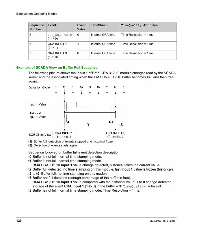
Behavior on Operating Modes
Example of SCADA View on Buffer Full Sequence
The following picture shows the Input 1 of BMX CRA 312 10 module changes read by the SCADA server and the associated timing when the BMX CRA 312 10 buffer becomes full, and then free again:
(1) Buffer full, detection of events stopped and historical frozen.(2) Detection of events starts again.
Sequence followed on buffer full event detection description:t0 Buffer is not full, normal time stamping mode.t1 Buffer is not full, normal time stamping mode.
BMX CRA 312 10 Input 1 value change detected, historical takes the current value.t2 Buffer full detected, no time stamping on this module, last Input 1 value is frozen (historical).t3 ... t6 Buffer full, no time stamping on this module.t7 Buffer not full detected (enough percentage of the buffer is free).
BMX CRA 312 10 Input 1 value compared with the historical value: 1 to 0 change detected, storage of the event CRA Input 1 (1 to 0) in the buffer with TimeQuality = Invalid.
t8 Buffer is not full, normal time stamping mode, Time Resolution = 1 ms.
5 SOE_UNCERTAIN(1 -> 0)
0 Internal CRA time Time Resolution = 1 ms
6 CRA INPUT 1(0 -> 1)
1 Internal CRA time Time Resolution = 1 ms
7 CRA INPUT 3(1 -> 0)
0 Internal CRA time Time Resolution = 1 ms
Sequence Number
Event Event Value
TimeStamp TimeQuality Attributes
126 EIO0000001217 04/2015
Behavior on Operating Modes
Restart of the SCADA Server
Overview
Restart of the SCADA server is assumed to occur while the time stamping modules are time stamping and their clock is synchronized.
SOE Sequence on Restart of the SCADA Server
Sequence followed on SCADA server restart: The events stored in the module buffer before SCADA server restart (and not read) are available
for the SCADA (events from sequence number 1 to 3 in the following table). The rest of the sequence is the same as sequences number 1 to 6 in the initial start SOE
sequence (see page 121) (sequences number 4 to 11 in the following table). Process values provided after SCADA server restart are signaled by an uncertain sequence of events (sequences number 4 to 8).
EIO0000001217 04/2015 127
Behavior on Operating Modes
The following table presents the SOE sequence on SCADA server restart provided by a BMX CRA 312 10 time stamping module with 3 time stamped inputs and 1 time stamped output:
Sequence Number
Event Event Value
TimeStamp TimeQuality Attributes
1 CRA INPUT 1(0 -> 1)
1 Internal CRA time Time Resolution = 1 ms
2 CRA INPUT 3(1 -> 0)
0 Internal CRA time Time Resolution = 1 ms
3 CRA OUTPUT 4(0 -> 1)
1 Internal CRA time Time Resolution = 1 ms
4 SOE_UNCERTAIN (1.)
(0 -> 1)
1 Internal CRA time Time Resolution = 1 ms
5 CRA INPUT 1(1 -> 0)
0 Internal CRA time TSInit
6 CRA INPUT 2(0 -> 1)
1 Internal CRA time TSInit
7 CRA INPUT 3(0 -> 1)
1 Internal CRA time TSInit
8 CRA OUTPUT 4(1 -> 0)
0 Internal CRA time TSInit
9 SOE_UNCERTAIN (1.)
(1 -> 0)
0 Internal CRA time Time Resolution = 1 ms
10 CRA INPUT 1(0 -> 1)
1 Internal CRA time Time Resolution = 1 ms
11 CRA INPUT 3(1 -> 0)
0 Internal CRA time Time Resolution = 1 ms
1. SOE_UNCERTAIN event appears only if events can be lost after start and connection of the SCADA server. SOE_UNCERTAIN event does not appear for the BMX ERT 1604 T module.
128 EIO0000001217 04/2015
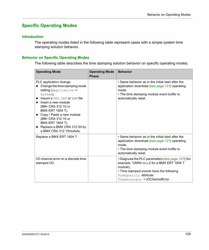
Behavior on Operating Modes
Specific Operating Modes
Introduction
The operating modes listed in the following table represent cases with a simple system time stamping solution behavior.
Behavior on Specific Operating Modes
The following table describes the time stamping solution behavior on specific operating modes:
Operating Mode Operating Mode Phase
Behavior
PLC application change: Change the time stamping mode
setting (Applicative -> System).
Import a XEF, ZEF or XHW file. Insert a new module
(BM• CRA 312 10 or BMX ERT 1604 T).
Copy / Paste a new module (BM• CRA 312 10 or BMX ERT 1604 T).
Replace a BMX CRA 312 00 by a BMX CRA 312 10module.
• Same behavior as in the initial start after the application download (see page 121) operating mode.• The time stamping module event buffer is automatically reset.
Replace a BMX ERT 1604 T • Same behavior as in the initial start after the application download (see page 121) operating mode.• The time stamping module event buffer is automatically reset.
I/O channel error on a discrete time stamped I/O.
• Diagnose the PLC parameters (see page 107) (for example, %MWr.m.c.2 for a BMX ERT 1604 T module).• Time stamped events have the following TimeQuality attribute: TimeAccuracy = IOChannelError.
EIO0000001217 04/2015 129
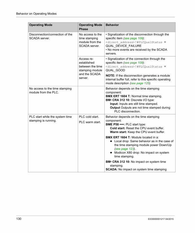
Behavior on Operating Modes
Disconnection/connection of the SCADA server.
No access to the time stamping module from the SCADA server.
• Signalization of the disconnection through the specific item (see page 109): <direct_address>!#PLCQualStatus = QUAL_DEVICE_FAILURE• No more events are received by the SCADA servers.
Access re-established between the time stamping module and the SCADA server.
• Signalization of the connection through the specific item (see page 109): <direct_address>!#PLCQualStatus = QUAL_GOOD
NOTE: If the disconnection generates a module internal buffer full, refer to this specific operating mode description (see page 125).
No access to the time stamping module from the PLC.
Behavior depends on the time stamping component:BMX ERT 1604 T: Normal time stamping.BM• CRA 312 10: Discrete I/O type:
Input: Inputs are still time stamped.Output Outputs are not time stamped during
PLC disconnection.
PLC start while the system time stamping is running.
PLC cold start. Behavior depends on the time stamping component:BME P58 ••••: PLC start type:
Cold start: Reset the CPU event buffer.Warm start: Keep the CPU event buffer.
BMX ERT 1604 T: Module located in a: Local drop: Same behavior as in the case of
the time stamping module power Down/Up (see page 123).
Modicon X80 drop: No impact on system time stamping.
BM• CRA 312 10: No impact on system time stamping.
SCADA: No impact on system time stamping
PLC warm start.
Operating Mode Operating Mode Phase
Behavior
130 EIO0000001217 04/2015
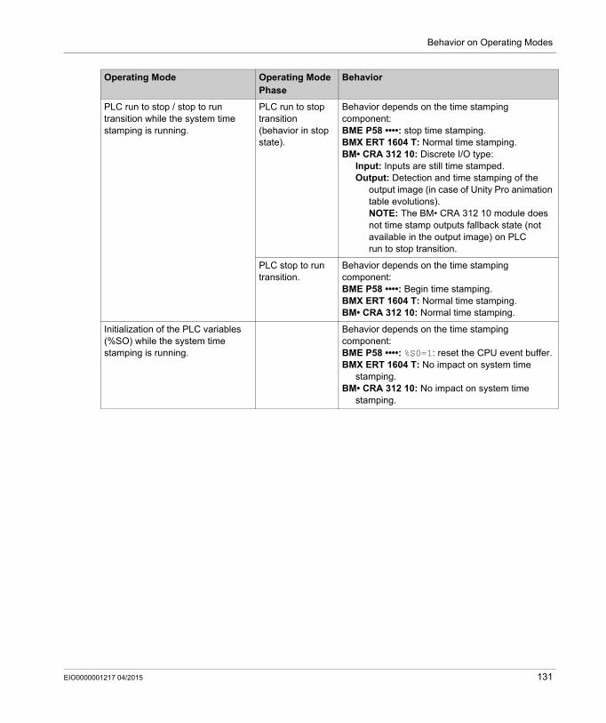
Behavior on Operating Modes
PLC run to stop / stop to run transition while the system time stamping is running.
PLC run to stop transition (behavior in stop state).
Behavior depends on the time stamping component:BME P58 ••••: stop time stamping.BMX ERT 1604 T: Normal time stamping.BM• CRA 312 10: Discrete I/O type:
Input: Inputs are still time stamped.Output: Detection and time stamping of the
output image (in case of Unity Pro animation table evolutions).NOTE: The BM• CRA 312 10 module does not time stamp outputs fallback state (not available in the output image) on PLC run to stop transition.
PLC stop to run transition.
Behavior depends on the time stamping component:BME P58 ••••: Begin time stamping.BMX ERT 1604 T: Normal time stamping.BM• CRA 312 10: Normal time stamping.
Initialization of the PLC variables (%SO) while the system time stamping is running.
Behavior depends on the time stamping component:BME P58 ••••: %S0=1: reset the CPU event buffer.BMX ERT 1604 T: No impact on system time
stamping.BM• CRA 312 10: No impact on system time
stamping.
Operating Mode Operating Mode Phase
Behavior
EIO0000001217 04/2015 131

Behavior on Operating Modes
132 EIO0000001217 04/2015
System Time Stamping
Behavior on Time Synchronization
EIO0000001217 04/2015
Behavior on Time Synchronization
Chapter 14Behavior on Time Synchronization
Time Synchronization
Time Synchronization on System Start
On system start, the time stamping modules begin to time stamp events without waiting for the initial time synchronization. To signal that the first synchronization has not been done yet (see page 121) to the SCADA server, the following parameters of TimeQuality are set to 1: ClockNotSynchronized ClockFailure
Once the time stamping module time is synchronized, ClockNotSynchronized and ClockFailure parameters are set to 0 in TimeQuality.
Time Synchronization When the System Is Running
When the system is running, each time stamping module periodically synchronizes its clock with the external clock reference. On synchronization, 3 situations appear:Module internal time is equal to external clock time: No change in module internal time.Module internal time is delayed compared to external clock time: Module internal time
synchronizes with external clock time.Module internal time is ahead of external clock time: Time stamp value cannot be
synchronized instantaneously with external clock, a specific mechanism takes place to increase the time stamp value step by step in order to catch the internal synchronized clock time. The goal of this mechanism is to keep time coherence in sequence of events (event n+1 cannot be time stamped with a time value lower than event n).Synchronization mechanism until time stamp value < module internal time (internal time cannot be accessed by the user): Every time stamping detection cycle, the time stamp value increments by 1 ms. TimeQuality = ClockInSync (0xx11011 bin) as long as time stamp value is higher than
internal time.
The time required to synchronize the time stamp value with the new internal time is called catch up time:Catch up time = (Internal time - Synchronized time received) x Detection cycle / (Detection cycle - Incrementation step)
EIO0000001217 04/2015 133
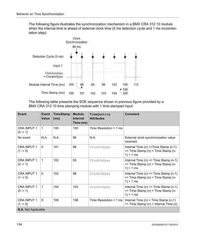
Behavior on Time Synchronization
The following figure illustrates the synchronization mechanism in a BMX CRA 312 10 module when the internal time is ahead of external clock time (5 ms detection cycle and 1 ms incremen-tation step):
The following table presents the SOE sequence shown in previous figure provided by a BMX CRA 312 10 time stamping module with 1 time stamped input:
Event Event Value
TimeStamp(ms)
Module Internal Time (ms)
TimeQuality Attributes
Comment
CRA INPUT 1(0 -> 1)
1 100 100 Time Resolution = 1 ms
No event N.A. N.A. 86 N.A. External clock synchronization value received.
CRA INPUT 1(1 -> 0)
0 101 88 ClockInSync Internal Time (n) <=Time Stamp (n-1)=> Time Stamp (n) = Time Stamp (n-1) + 1 ms
CRA INPUT 1(0 -> 1)
1 102 93 ClockInSync Internal Time (n) <= Time Stamp (n-1)=> Time Stamp (n) = Time Stamp (n-1) + 1 ms
CRA INPUT 1(1 -> 0)
0 103 98 ClockInSync Internal Time (n) <= Time Stamp (n-1)=> Time Stamp (n) = Time Stamp (n-1) + 1 ms
CRA INPUT 1(0 -> 1)
1 104 103 ClockInSync Internal Time (n) <= Time Stamp (n-1)=> Time Stamp (n) = Time Stamp (n-1) + 1 ms
CRA INPUT 1(1 -> 0)
0 108 108 Time Resolution = 1 ms Internal Time (n) > Time Stamp (n-1)=> Time Stamp (n) = Internal Time (n)
N.A. Not Applicable
134 EIO0000001217 04/2015
Behavior on Time Synchronization
In this example: Catch up time = (100 - 86) x 5 / (5 - 1). Catch up time = 17.5 ms (around 4 detection cycles of 5 ms).
NOTE: The following list presents some fields available in previous table and their corresponding fields in Vijeo Citect SOE page (see page 111): Event: Data available in Tag, Name and Message fields in Vijeo Citect SOE display. Timestamp: Data available in Date and Time fields in Vijeo Citect SOE display. TimeQuality Attributes: Data available in Quality and TSQuality fields in Vijeo Citect SOE
display.
Time Synchronization Lost When the System Is Running
If the time synchronization is lost (no link with the external time reference), the time stamping module time stamps events with its internal time, based on the latest successful synchronization.
NOTE: If the time has never been synchronized, then the internal time is the free running time from epoch.
As in the initial start case, to manage that situation, CLOCK_NOT_SYNC parameter is set to 1 (and ClockNotSynchronized parameter is set to 1 in TimeQuality byte).
Once the time stamping module time is synchronized, CLOCK_NOT_SYNC parameter is set to 0 (and ClockNotSynchronized parameter is set to 0 in TimeQuality byte).
NOTE: As the time synchronization mechanism is specific to each module, the time interval between the loss of time synchronization and the setting of CLOCK_NOT_SYNC parameter is different for a BMX ERT 1604 T and a BM• CRA 312 10 module.
Time interval between the loss of time synchronization and the setting of CLOCK_NOT_SYNC parameter: for a BMX ERT 1604 T: 10 seconds (IRIG-B) or 10 minutes (DCF77). for a BM• CRA 312 10: 3 seconds after the scheduled polling time.
EIO0000001217 04/2015 135

Behavior on Time Synchronization
136 EIO0000001217 04/2015
System Time Stamping
Interface with 3rd Party Client SCADA
EIO0000001217 04/2015
How to Interface with a 3rd Party Client SCADA
Part VHow to Interface with a 3rd Party Client SCADA
EIO0000001217 04/2015 137

Interface with 3rd Party Client SCADA
138 EIO0000001217 04/2015
System Time Stamping
3rd Party Client SCADA
EIO0000001217 04/2015
3rd Party Client SCADA
Chapter 153rd Party Client SCADA
Overview
This chapter describes the steps that an OPC DA (version 2.04 or later) client needs to follow in order to operate the system time stamping solution with OFS. It is intended for OPC client developers.
What Is in This Chapter?
This chapter contains the following topics:
Topic Page
OPC Events Group 140
Operation Steps 141
Optional Functionalities 142
##TSEventsGroup## OnDataChange Interface 143
EIO0000001217 04/2015 139
3rd Party Client SCADA
OPC Events Group
Introduction
3rd party SCADA needs to use OFS software services to implement the system time stamping solution.
Event Group
A particular OPC group named: ##TSEventsGroup## needs to be created to manage time stamped variables. This group is referenced as Events Group in this section.
Each OPC client can only create 1 OPC events group.
This Events Group complies with the following rules: If the Service support tab is not set to Available (see page 76) for the OFS alias of an item,
that item is not added and an E_FAIL error detected message is returned. Items for which the Time-stamped Event Support custom property (see page 76) is set to 1
can be added to the Events Group.Items for which the Time-stamped Event Support custom property (see page 76) is set to 0 can also be added to the Events Group but a message is displayed in OFS diagnostics window (Example of message: Item ‘myvar’ has not time-stamped property set; it will be ignored).
The same item can not be added more than once in the Events Group otherwise an OPC_E_DUPLICATE_NAME error detected message is returned.
Items associated to a same OFS alias cannot be added in several client Events Group; otherwise an E_FAIL error detected message is returned.
OFS specific items can not be added in the Events Group; otherwise an E_FAIL error detected message is returned.
If one of the following operations is performed, an E_FAIL error detected message is returned immediately: IOPCGroupStateMgt::SetName() IOPCGroupStateMgt::CloneGroup() Any IOPCSyncIO method Any IOPCSyncIO2 method
NOTE: A standard OPC group cannot be renamed ##TSEventsGroup## .
For more details, refer to topic Time Stamped Events Configuration in OPC Factory Server User Manual (see page 12).
Specific Items
NOTE: #TSEventItemsReady item has to be placed in a fast update rate group (200 ms).
140 EIO0000001217 04/2015
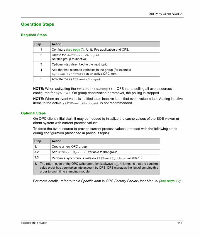
3rd Party Client SCADA
Operation Steps
Required Steps
NOTE: When activating the ##TSEventsGroup## , OFS starts polling all event sources configured for myAlias. On group deactivation or removal, the polling is stopped.
NOTE: When an event value is notified to an inactive item, that event value is lost. Adding inactive items to the active ##TSEventsGroup## is not recommended.
Optional Steps
On OPC client initial start, it may be needed to initialize the cache values of the SOE viewer or alarm system with current process values.
To force the event source to provide current process values, proceed with the following steps during configuration (described in previous topic):
For more details, refer to topic Specific Item in OPC Factory Server User Manual (see page 12).
Step Action
1 Configure (see page 71) Unity Pro application and OFS.
2 Create the ##TSEventsGroup##.Set this group to inactive.
3 Optional step described in the next topic.
4 Add the time stamped variables in the group (for example myAlias!eventVar1) as an active OPC item.
5 Activate the ##TSEventsGroup##.
Step Action
3.1 Create a new OPC group.
3.2 Add #TSEventSynchro variable to that group.
3.3 Perform a synchronous write on #TSEventSynchro variable (1.).
1. The return code of the OPC write operation is always S_OK; it means that the synchro value order has been taken into account by OFS. OFS manages the fact of sending this order to each time stamping module.
EIO0000001217 04/2015 141
3rd Party Client SCADA
Optional Functionalities
OPC Item Property 5012
As described in the chapter OFS settings (see page 76), this OPC item property can be read during a browse operation to discover if a variable is configured as a time stamp variable in Unity Pro application.
Time stamp variables can be added to ##TSEventsGroup##. For more details, refer to topic Time Stamped Events Configuration .
<<system>>!#ClientAlive Specific Item
This item can be periodically written to inform OFS that the OPC client is alive. If OFS detects that the client is missing, OFS deactivates all active OPC groups including ##TSEventsGroup##.
For more details, refer to topic Time Stamped Events Configuration in OPC Factory Server User Manual (see page 12).
#PLCQualStatus Specific Item
This item can be activated to diagnose the connection state of a PLC device or an event source device.
For more details, refer to topic Specific Item in OPC Factory Server User Manual (see page 12).
142 EIO0000001217 04/2015
3rd Party Client SCADA
##TSEventsGroup## OnDataChange Interface
Overview
The following topics details IOPCDataCallback::OnDataChange() OPC method invoked in the ##TSEventsGroup##.
An item in the ##TSEventsGroup## is notified with a value, time, and quality parameter described in the following topics.
Value
Value is the event value (Value field in the event data format (see page 153)) converted to VT_BOOL.
Time
Time is the event time stamp (DateAndTime field in the event data format (see page 153)) converted to FILETIME.
The following conversion is applied to the time stamp: pftTimeStamps = 10 000 000 * (DateAndTime.SecondSinceEpoch + 11 644 473 600 + (DateAndTime.FractionOfSecond * 2 power –24))
NOTE: If the Quality of an event indicates a ClockFailure value, the Time field is patched by OFS with the local time of the OFS machine.
Quality
Quality is a WORD and it is the combination of the event time quality and standard OPC quality.
Quality format: Byte 0: OPC Quality Byte 1: TimeQuality (TimeQuality field in the event data format (see page 153)).
OPC_Quality value: OPC_QUALITY_BAD or QUAL_CONFIGURATION_ERROR (04 hex): A configuration error is
detected on the item (unknown event source for example) OPC_QUALITY_GOOD (C0 hex): Normal working condition.
EIO0000001217 04/2015 143
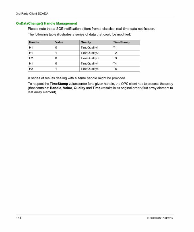
3rd Party Client SCADA
OnDataChange() Handle Management
Please note that a SOE notification differs from a classical real-time data notification.
The following table illustrates a series of data that could be modified:
A series of results dealing with a same handle might be provided.
To respect the TimeStamp values order for a given handle, the OPC client has to process the array (that contains: Handle, Value, Quality and Time) results in its original order (first array element to last array element).
Handle Value Quality TimeStamp
H1 0 TimeQuality1 T1
H1 1 TimeQuality2 T2
H2 0 TimeQuality3 T3
H1 0 TimeQuality4 T4
H2 1 TimeQuality5 T5
144 EIO0000001217 04/2015
System Time Stamping
Troubleshooting
EIO0000001217 04/2015
Troubleshooting
Part VITroubleshooting
EIO0000001217 04/2015 145

Troubleshooting
146 EIO0000001217 04/2015
System Time Stamping
Troubleshooting SOE Page
EIO0000001217 04/2015
Troubleshooting SOE Page in Vijeo Citect V7.30
Chapter 16Troubleshooting SOE Page in Vijeo Citect V7.30
Vijeo Citect SOE Display Troubleshooting
Introduction
The following pages provide actions to perform when: SOE page is empty SOE page displays old events with recent events not shown
SOE Page Is Empty
Possible cause for an empty SOE page (non-exhaustive): The system is not able to get events or there are no events in the system.
Example of use cases which may lead to an empty SOE page: The alarm server is busy and cannot answer the request in the given time. The client display is not connected to the alarm server. The client user does not have the privileges to see the existing events.
Actions to perform:
Step Action
1 Check that information is displayed in the active alarm page.If the active alarm page is: empty, then proceed with following steps not empty, then proceed from step 5
2 Check in the hardware alarms and verify that your client is connected to the alarm server (a detected error is displayed when the alarm server is not connected).
3 Verify that you did not deactivate the cluster for this client. More details on [Client]Cluster parameter are provided in the Parameters section of Vijeo Citect User Guide or Vijeo Citect Help (see page 12).
4 Verify that you are logged in with the appropriate level of privileges.
5 Check that no filter is applied, filtering can generate an empty recordset.
6 Try to decrease the requested range by using the filter capability (use filter to request events for the last hour or for a particular tag for example).
EIO0000001217 04/2015 147
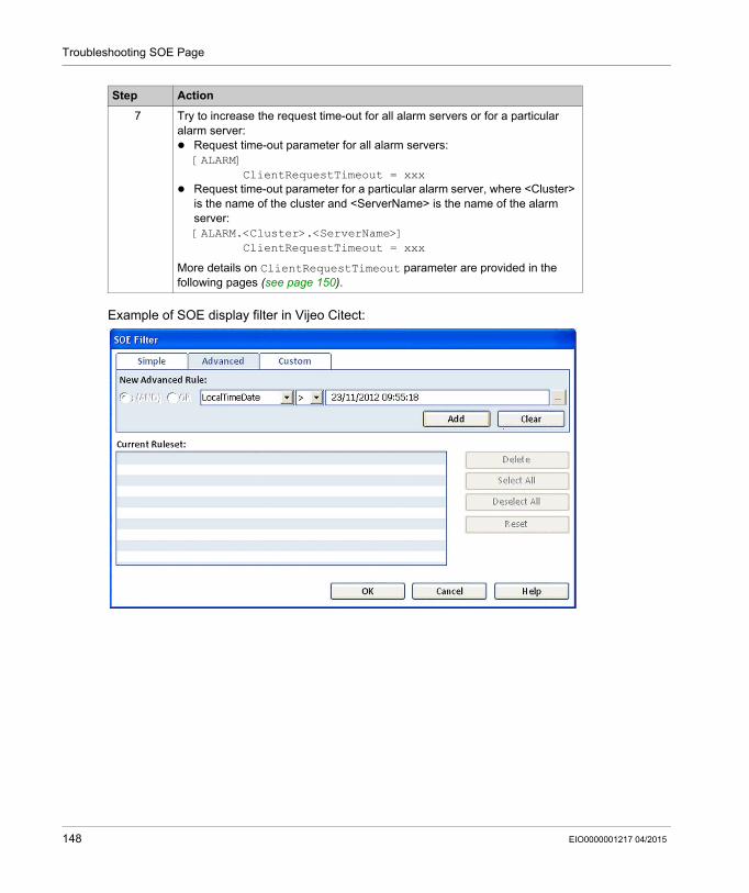
Troubleshooting SOE Page
Example of SOE display filter in Vijeo Citect:
7 Try to increase the request time-out for all alarm servers or for a particular alarm server: Request time-out parameter for all alarm servers:
[ALARM]ClientRequestTimeout = xxx
Request time-out parameter for a particular alarm server, where <Cluster> is the name of the cluster and <ServerName> is the name of the alarm server:[ALARM.<Cluster>.<ServerName>]
ClientRequestTimeout = xxx
More details on ClientRequestTimeout parameter are provided in the following pages (see page 150).
Step Action
148 EIO0000001217 04/2015
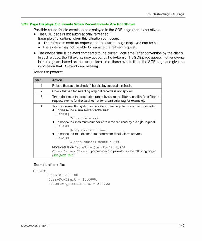
Troubleshooting SOE Page
SOE Page Displays Old Events While Recent Events Are Not Shown
Possible cause for old events to be displayed in the SOE page (non-exhaustive): The SOE page is not automatically refreshed.
Example of situations when this situation can occur: The refresh is done on request and the current page displayed can be old. The system may not be able to manage the refresh request.
The device time is delayed compared to the current local time (after conversion by the client). In such a case, the TS events may appear at the bottom of the SOE page queue. If other events in the page are based on the current local time, those events fill-up the SOE page and give the impression that TS events are missing.
Actions to perform:
Example of INI file:
[alarm]CacheSize = 80QueryRowLimit = 1000000ClientRequestTimeout = 300000
Step Action
1 Reload the page to check if the display needed a refresh.
2 Check that a filter selecting only old records is not applied.
3 Try to decrease the requested range by using the filter capability (use filter to request events for the last hour or for a particular tag for example).
4 Try to increase the system capabilities to manage large number of events: Increase the alarm server cache size:
[ALARM]CacheSize = xxx
Increase the maximum number of records returned by a single request:[ALARM]
QueryRowLimit = xxx Increase the request time-out parameter for all alarm servers:
[ALARM]ClientRequestTimeout = xxx
More details on CacheSize, QueryRowLimit, and ClientRequestTimeout parameters are provided in the following pages (see page 150).
EIO0000001217 04/2015 149
Troubleshooting SOE Page
Parameters Definitions in Vijeo Citect V7.30
ClientRequestTimeout: Definition: this parameter defines the amount of time, in milliseconds, in which the client can
request data from a server. If the server has not responded by the end of this time, the request has been unsuccessful.
Allowable values: 0 to 4294967295 Default value: 120000
CacheSize: Definition: this parameter defines the amount of memory (in megabytes) dedicated to the
storage of event data. For many systems, the default setting of 25 MB is appropriate. However, if your system is experiencing difficulties with server performance and the cache size needs to be adjusted, you can alter the cache size settings as required.
Allowable values: 0 to 400 Default value: 25
QueryRowLimit: Definition: defines the maximum number of rows that can be returned in the result set for a
single query. Increasing the QueryRowLimit may affect performance. Allowable values: 0 to 4294967295 Default value: 200000
150 EIO0000001217 04/2015

System Time Stamping
EIO0000001217 04/2015
Appendices
E
IO0000001217 04/2015 151
152 EIO0000001217 04/2015
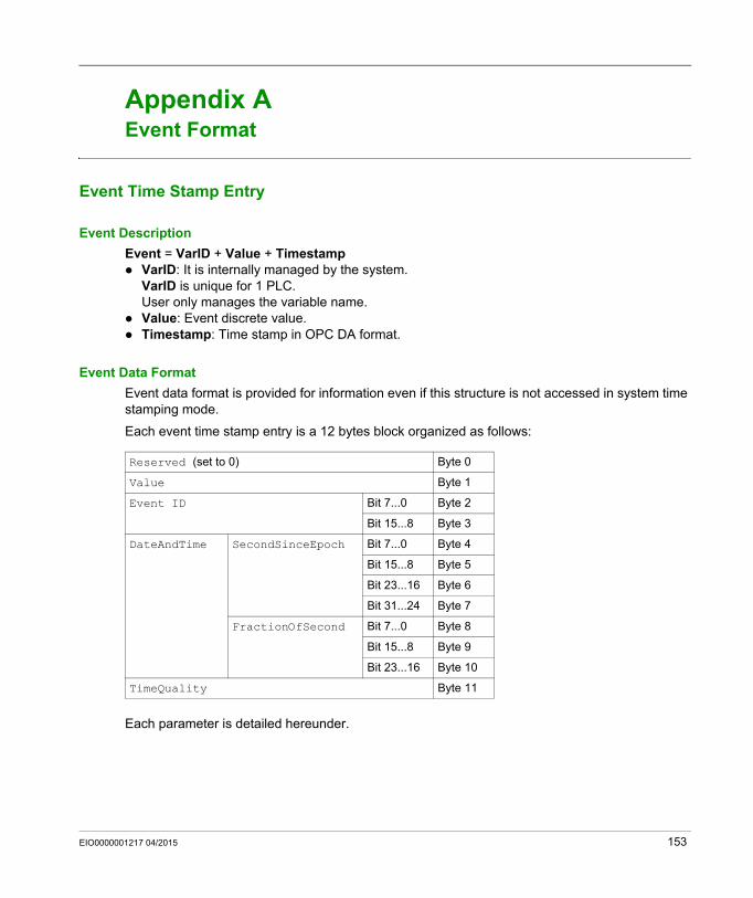
System Time Stamping
Event Format
EIO0000001217 04/2015
Event Format
Appendix AEvent Format
Event Time Stamp Entry
Event Description
Event = VarID + Value + Timestamp VarID: It is internally managed by the system.
VarID is unique for 1 PLC.User only manages the variable name.
Value: Event discrete value. Timestamp: Time stamp in OPC DA format.
Event Data Format
Event data format is provided for information even if this structure is not accessed in system time stamping mode.
Each event time stamp entry is a 12 bytes block organized as follows:
Each parameter is detailed hereunder.
Reserved (set to 0) Byte 0
Value Byte 1
Event ID Bit 7...0 Byte 2
Bit 15...8 Byte 3
DateAndTime SecondSinceEpoch Bit 7...0 Byte 4
Bit 15...8 Byte 5
Bit 23...16 Byte 6
Bit 31...24 Byte 7
FractionOfSecond Bit 7...0 Byte 8
Bit 15...8 Byte 9
Bit 23...16 Byte 10
TimeQuality Byte 11
EIO0000001217 04/2015 153
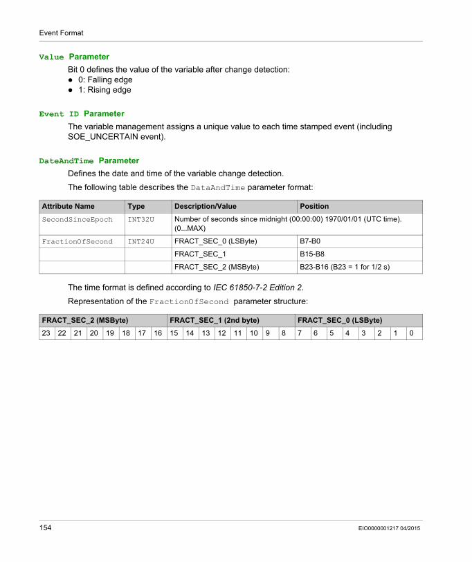
Event Format
Value Parameter
Bit 0 defines the value of the variable after change detection: 0: Falling edge 1: Rising edge
Event ID Parameter
The variable management assigns a unique value to each time stamped event (including SOE_UNCERTAIN event).
DateAndTime Parameter
Defines the date and time of the variable change detection.
The following table describes the DataAndTime parameter format:
The time format is defined according to IEC 61850-7-2 Edition 2.
Representation of the FractionOfSecond parameter structure:
Attribute Name Type Description/Value Position
SecondSinceEpoch INT32U Number of seconds since midnight (00:00:00) 1970/01/01 (UTC time).(0...MAX)
FractionOfSecond INT24U FRACT_SEC_0 (LSByte) B7-B0
FRACT_SEC_1 B15-B8
FRACT_SEC_2 (MSByte) B23-B16 (B23 = 1 for 1/2 s)
FRACT_SEC_2 (MSByte) FRACT_SEC_1 (2nd byte) FRACT_SEC_0 (LSByte)
23 22 21 20 19 18 17 16 15 14 13 12 11 10 9 8 7 6 5 4 3 2 1 0
154 EIO0000001217 04/2015
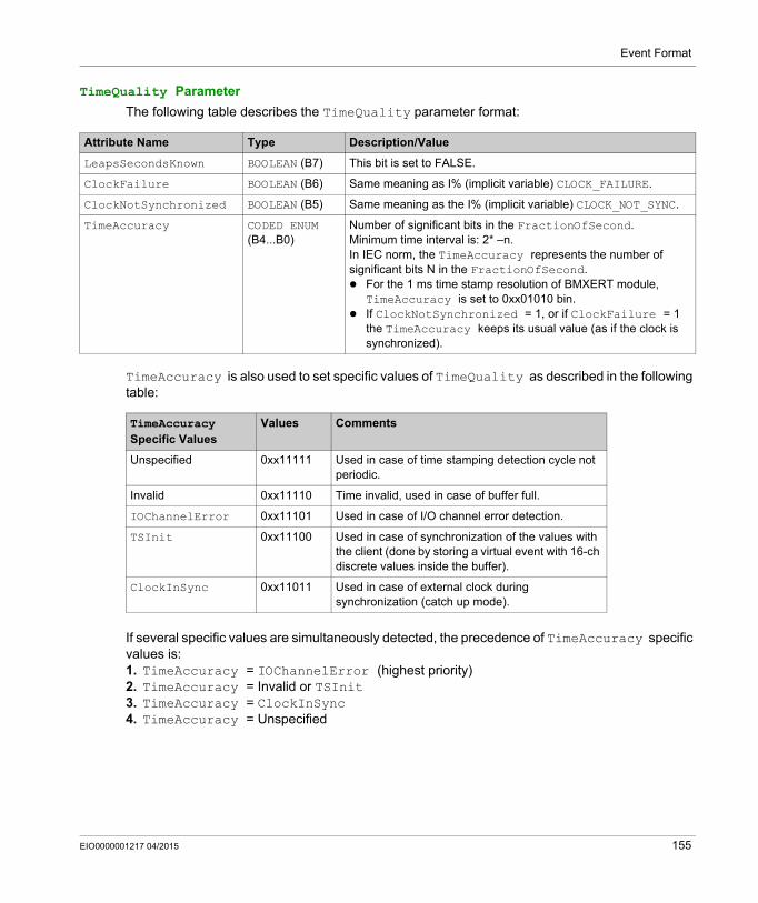
Event Format
TimeQuality Parameter
The following table describes the TimeQuality parameter format:
TimeAccuracy is also used to set specific values of TimeQuality as described in the following table:
If several specific values are simultaneously detected, the precedence of TimeAccuracy specific values is:1. TimeAccuracy = IOChannelError (highest priority)2. TimeAccuracy = Invalid or TSInit3. TimeAccuracy = ClockInSync4. TimeAccuracy = Unspecified
Attribute Name Type Description/Value
LeapsSecondsKnown BOOLEAN (B7) This bit is set to FALSE.
ClockFailure BOOLEAN (B6) Same meaning as I% (implicit variable) CLOCK_FAILURE.
ClockNotSynchronized BOOLEAN (B5) Same meaning as the I% (implicit variable) CLOCK_NOT_SYNC.
TimeAccuracy CODED ENUM (B4...B0)
Number of significant bits in the FractionOfSecond.Minimum time interval is: 2* –n.In IEC norm, the TimeAccuracy represents the number of significant bits N in the FractionOfSecond. For the 1 ms time stamp resolution of BMXERT module,
TimeAccuracy is set to 0xx01010 bin. If ClockNotSynchronized = 1, or if ClockFailure = 1
the TimeAccuracy keeps its usual value (as if the clock is synchronized).
TimeAccuracy Specific Values
Values Comments
Unspecified 0xx11111 Used in case of time stamping detection cycle not periodic.
Invalid 0xx11110 Time invalid, used in case of buffer full.
IOChannelError 0xx11101 Used in case of I/O channel error detection.
TSInit 0xx11100 Used in case of synchronization of the values with the client (done by storing a virtual event with 16-ch discrete values inside the buffer).
ClockInSync 0xx11011 Used in case of external clock during synchronization (catch up mode).
EIO0000001217 04/2015 155

Event Format
156 EIO0000001217 04/2015
System Time Stamping
Glossary
EIO0000001217 04/2015
Glossary
H
HMIHuman Machine Interface. An HMI is a device that displays process data to a human operator, who in turn, uses the HMI to control the process.
An HMI is typically connected to a SCADA system to provide diagnostics and management data (such as scheduled maintenance procedures and detailed schematics for a particular machine or sensor).
Hot StandbyA high-availability Quantum control system with a first PLC (primary) and a second PLC (standby) that maintains up-to-date system status. If the primary PLC becomes inoperable, the standby PLC takes control of the system.
O
OFS OPC Factory Server. OFS is a multi-controller data server which is able to communicate with PLCs in order to supply the OPC clients with data.
OPCOLE for Process Control
OPC DAOLE for Process Control Data Access. OPC DA is a group of standards that provides specifications for communicating real-time data.
S
SCADASupervisory Control and Data Acquisition. SCADA usually refers to centralized systems which monitor and control entire sites or systems spread out over large areas.
Vijeo Citect versions from V7.30 provide an SOE view.
For system time stamping, it refers to Vijeo Citect or 3rd party SCADA with OPC DA interface.
SOESequence Of Events
EIO0000001217 04/2015 157

Glossary
158 EIO0000001217 04/2015
System Time Stamping
Index
EIO0000001217 04/2015
Index
0-93rd party
SCADA, 137
Aactivate
service, 71architecture
typical, 39
BBMECRA31210, 33
clock, 69variables, 89
BMEP58xxxx, 31clock, 66variables, 81
BMXCRA31210, 33clock, 69variables, 89
BMXERT1604T, 32clock, 68variables, 82
BMXNOC0401, 36BMXNOE0100, 36BMXNOE0101, 36buffer full
operating mode, 125
Cclock
BMECRA31210, 69BMEP58xxxx, 66BMXCRA31210, 69BMXERT1604T, 68
commissioning, 103diagnostic, 105
EIO0000001217 04/2015
communicationparameter, 91performance, 92select, 91
components, 25
Ddiagnostic
commissioning, 105hardware, 114PLC, 107
disconnection (SCADA server)operating mode, 129
Hhardware
diagnostic, 114
II/O channel error
operating mode, 129initial start
operating mode, 121initialize PLC variables
operating mode, 129internal
variable, 31
Mmodule
select, 59module disconnected from PLC
operating mode, 129
159
Index
OOFS, 29, 76
setting, 94operating mode, 119, 120
buffer full, 125disconnection (SCADA server) , 129I/O channel error, 129initial start, 121initialize PLC variables, 129module disconnected from PLC, 129PLC run to stop / stop to run, 129PLC start, 129power down/up, 123replace module, 129restart SCADA server, 127
operation, 103
Pparameter
communication, 91Vijeo Citect, 96
performancecommunication, 92
PLCdiagnostic, 107
PLC run to stop / stop to runoperating mode, 129
PLC startoperating mode, 129
power down/upoperating mode, 123
Rreplace module
operating mode, 129resolution
time stamp, 59restart SCADA server
operating mode, 127router, 35
160
SSCADA, 27
3rd party, 137select
communication, 91module, 59time source, 61time synchronization, 61variables, 79
serviceactivate, 71
set parametersVijeo Citect, 95
settingOFS, 94
SOE pagetroubleshooting, 147
synchronizationtime, 28, 133
system time stamping, 18
Ttime
synchronization, 28, 133time source
select, 61time stamp
resolution, 59variables, 79
time stamping, 18time synchronization
select, 61troubleshooting
SOE page, 147typical
architecture, 39
UUnity Pro, 30, 72
EIO0000001217 04/2015
Index
Vvariable
internal, 31variables
BMECRA31210, 89BMEP58xxxx, 81BMXCRA31210, 89BMXERT1604T, 82select, 79time stamp, 79
version, 37Vijeo Citect, 26
parameter, 96set parameters, 95
EIO0000001217 04/2015
161
Index
162 EIO0000001217 04/2015