system transient/time responseguppy.mpe.nus.edu.sg/anpoo/fbcontrola/5system response.pdf ·...
TRANSCRIPT
ME2142/ME2142E Feedback Control Systems1
System Transient/Time ResponseSystem Transient/Time Response
ME2142/ME2142E Feedback Control SystemsME2142/ME2142E Feedback Control Systems

ME2142/ME2142E Feedback Control Systems2
System responseSystem response
For stable systems, the magnitude of the transient response decreases with time and ultimately vanishes leaving only the steady-state response. It is always associated with the component
0with ae at

ME2142/ME2142E Feedback Control Systems3
System Characteristic EquationSystem Characteristic Equation
Consider the system with the transfer function, Gc(s) as shown
Gc(s)System
Input OutputR(s) C(s)
The system’s characteristic equation is given by
0)( sDc
with
where Nc(s) and Dc(s) are polynomials of s.
)()(
)()()(
sDsN
sGsRsC
c
cc
Note that the characteristic equation is a property of the system and is not dependent on the input.

ME2142/ME2142E Feedback Control Systems4
System Characteristic EquationSystem Characteristic Equation
ExamplesExamples
Spring-mass-damper (Slide 9: Modelling of Physical Systems)
Transfer Function
Characteristic Eqn:
Spring-mass-damper (Slide 9: Modelling of Physical Systems)
Transfer Function
Characteristic Eqn:
KbsmsKbs
sXsX
sGi
o
2)()(
)(
02 Kbsms
R-C circuit (Slide 12: Modelling of Physical Systems)
Transfer Function
Characteristic Eqn:
R-C circuit (Slide 12: Modelling of Physical Systems)
Transfer Function
Characteristic Eqn:
11
RCsE
E
i
o
01 RCs
Closed-loop feedback system (Slide 8: Block Diagram Algebra)
Transfer Function
Characteristic Eqn:
Closed-loop feedback system (Slide 8: Block Diagram Algebra)
Transfer Function
Characteristic Eqn:
GHG
RC
1
01 GH

ME2142/ME2142E Feedback Control Systems5
System Characteristic EquationSystem Characteristic Equation
The roots of this equation are the closed-loop poles and they determine the transient response of the system.
Characteristic equation
0)( sDc
)()(
)()()(
sDsN
sGsRsC
c
cc
If all the roots, pr, are negative, then the transient response will eventually die away as t increases.
Each root, p, of this equation will contribute a term in the time response of the system. Or
ptAetc )(
pte
But if any of the roots is positive, then the transient response will grow without bounds as time increases. The system is then said to be unstable.

ME2142/ME2142E Feedback Control Systems6
Given a dynamic system:Given a dynamic system:
System ResponseSystem Response
We use Standard test inputs to excite system and observe
response Classify systems with similar characteristics and
identify their performance characteristics with system parameters.
How do we specify the characteristics of the response required?
How do we compare it with another system?
How do we know whether it’s response will adequately meet our needs?
How will we know how it will respond to different inputs?

ME2142/ME2142E Feedback Control Systems7
2) Ramp input2) Ramp input
000)(
ttAttr
2)(
sAsR
At
t = 0
r(t)
t
System Response –Test signalsSystem Response –Test signals
1) Step input1) Step input
000)(
ttAtr
sAsR )(
A
t = 0
r(t)
t
When A = 1, we have a unit step input.Used to study response to sudden changes in input.
When A = 1, we have a unit ramp input.Used to study response to gradual changes in input.

ME2142/ME2142E Feedback Control Systems8
4) Sinusoidal input4) Sinusoidal input
000sin)(
tttAtr
t
r(t)
t = 0
3) Impulse input
is the unit-impulse function or Dirac delta function
3) Impulse input
is the unit-impulse function or Dirac delta function
)0()( Atr
AsR )(
A
t = 0
r(t)
t
System Response –Test signalsSystem Response –Test signals
When A = 1, we have a unit impulse input.Used to study response to sudden shocks or impacts.
Used for frequency response analysis.Important method. Will be discuss in the second half of course.
Using test signals (1) to (3) are often known as time response or transient response analysis while using test signal (4) is known as frequency response.

ME2142/ME2142E Feedback Control Systems9
System Response – First-order systemsSystem Response – First-order systems
A first-order system can always be written in the standard form
T is known as the time constant and determines the speed of response.
A first-order system can always be written in the standard form
T is known as the time constant and determines the speed of response.
1)()(
TsK
sRsC
ExamplesExamples
Spring-damper system (Slide 7 of Modelling of Physical Systems)
.
Spring-damper system (Slide 7 of Modelling of Physical Systems)
. KbsK
sXsY
)()(
KbT
Ts
with
11
RC circuit (Slide 12 of Modelling of Physical Systems)
.
RC circuit (Slide 12 of Modelling of Physical Systems)
.RCT
TsRCsEE
i
o
with1
11
1
If the transfer function are the same, then the response y(t) and eo(t)will be the same for the same inputs in x(t) and ei(t)..

ME2142/ME2142E Feedback Control Systems10
System Response – First-order systemsSystem Response – First-order systems
with
.
with
.
1)()(
TsK
sRsC
Response to a unit step inputResponse to a unit step input
ssR 1)(
Thus )(1
)( sRTs
KsC
sTs
TK 1)/1(
/
Ts
BsA
/1
Multiplying both sides by s and letting s=0 gives A = K
Multiplying both sides by (s+1/T) and letting s = -1/T gives B = -K
ThereforeTs
KsKsC
/1)(
Using tables
)1()( // TtTt eKKeKtc 0for t

ME2142/ME2142E Feedback Control Systems11
System Response – First-order systemsSystem Response – First-order systems
Response to a unit step inputResponse to a unit step input )1()( / Ttetc For K = 1
Note: The smaller the time constant T, the faster the response.The shape is always the same.

ME2142/ME2142E Feedback Control Systems12
System Response – First-order systemsSystem Response – First-order systems
with
.
with
.
1)()(
TsK
sRsC
Response to a unit ramp inputResponse to a unit ramp input
Thus )(1
)( sRTs
KsC
2
1)(s
sR
2
1)/1(
/sTs
TK
)/1(2 Ts
KTs
KTsK
For K = 1,
)1()( / TteTttc
with the error e(t) = r(t) – c(t)
Using tables
0for t)()( / TtTeTtKtc
)1( / TteT
r(t)
t = 0
r(t)
t
ess=Tc(t)
r(t)
t = 0
r(t)
t
ess=Tc(t)

ME2142/ME2142E Feedback Control Systems13
System Response – First-order systemsSystem Response – First-order systems
with
.
with
.
1)()(
TsK
sRsC
Response to a unit impulse inputResponse to a unit impulse input
1)( sR
ThusTs
TKTs
KsC/1
/1
)(
Or TteTKtc /)(
For K = 1,
TteT
tc /1)(
r(t)
t = 0
1
t
r(t)
t = 0
1
t

ME2142/ME2142E Feedback Control Systems14
The transient response all contains the term which is determined by the root of the characteristic equation and the parameter T.
The transient response all contains the term which is determined by the root of the characteristic equation and the parameter T.
Tte /
Response toResponse to
Unit Impulse
TteTKtc /
1 )(
System Response – Linear time-invariant systems
System Response – Linear time-invariant systems
1)()(
TsK
sRsCPropertiesProperties Characteristic EquationCharacteristic Equation
TsTs 101
Note that the unit step is the derivative of the unit ramp, and the unit impulse is the derivative of the unit step.
Note that similarly, c2(t) is the derivative of c3(t) and c1(t) is the derivative of c2(t) .
For linear time-invariant systems, the response to the derivative of an input can be obtained by taking the derivative of the response to the input.
Unit Step
)1()( /2
TteKtc
Unit Ramp
)()( /3
TtTeTtKtc

ME2142/ME2142E Feedback Control Systems15
Block DiagramBlock Diagram
Permanent Magnet DC MotorPermanent Magnet DC Motor
e i
Ra La
eK J
bT
e i
Ra La
eK J
bT
The Permanent Magnet DC motor.The Permanent Magnet DC motor.
Governing equationsGoverning equations
eaa KdtdiLiRe
iKT t
bdtdJT
IsLRKE aae )(
IKT t
)( bJsT
+
-
E I
aa RsL 1
eK
tKT
bJs 1
eK
+
-
E
eK
eK
))(( bJsRsLK
aa
t

ME2142/ME2142E Feedback Control Systems16
+
-
E
eK
eK
))(( bJsRsLK
aa
t
+
-
E
eK
eK
))(( bJsRsLK
aa
t
The Permanent Magnet DC motor.The Permanent Magnet DC motor.
Commonly
bJ
RL
a
a
La can then be neglected
Block diagram then becomesBlock diagram then becomes
E +
-
eK
bJsRK at
/E +
-
eK
bJsRK at
/
GHG
E
1
)(/
1
)(/
bJsRKK
bJsRK
aet
at
aet
at
RKKbJsRK
//
1
sK
aet
at
RKKbRK
K/
/with
aet RKKbJ
/
Permanent Magnet DC MotorPermanent Magnet DC Motor

ME2142/ME2142E Feedback Control Systems17
aet RKKbJ
/
Speed Control of the DC MotorSpeed Control of the DC Motor
1sK
E
The response to a unit step input is first order with a time constant ofCan we make the response faster?
t = 0 t
K
With speed feedbackWith speed feedback
1sK
E Error+
-
VKc
Controller1
1
1
sKK
sKK
V c
c
KKs
KK
c
c
1 1''
sK
KKc
1'with
KKKK
Kc
c
1'
The resultant system is still first-order but the time constant is now much smaller, thus a much faster response.
Motor byitself
Motor byitself
ME2142/ME2142E Feedback Control Systems18
System Response – Second-order systemsSystem Response – Second-order systems
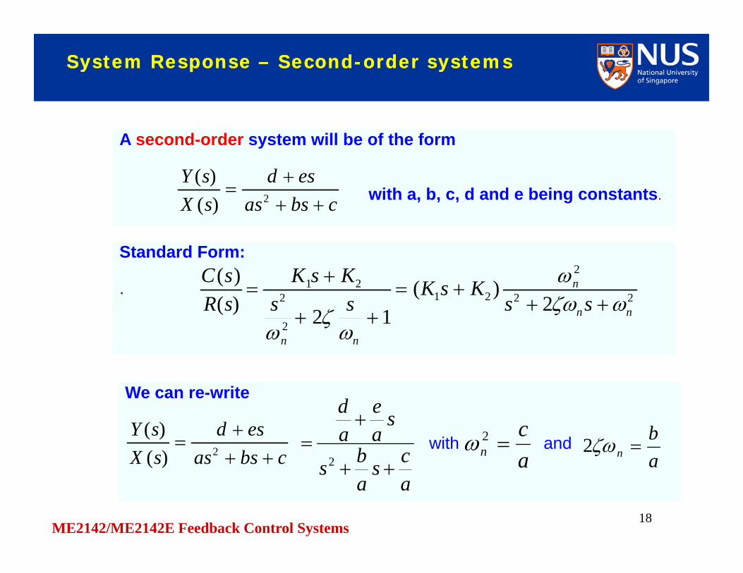
A second-order system will be of the form
with a, b, c, d and e being constants.
A second-order system will be of the form
with a, b, c, d and e being constants.cbsasesd
sXsY
2)(
)(
Standard Form:
.
Standard Form:
. 22
2
21
2
221
2)(
12)()(
nn
n
nn
ssKsK
ssKsK
sRsC
We can re-writeWe can re-write
cbsasesd
sXsY
2)(
)(
acs
abs
sae
ad
2with and
ac
n 2ab
n 2

ME2142/ME2142E Feedback Control Systems19
System Response – Second-order systemsSystem Response – Second-order systems
ExamplesExamples
RLC circuit (see Modelling of Physical Systems)
.
RLC circuit (see Modelling of Physical Systems)
.
11
)()(
2
RCsLCssEsE
i
o with andLCn12
LR
n 2
LCs
LRs
LC1
1
2
LCs
LRs
LC1
1
2
Spring-mass-damper.Spring-mass-damper.
KbsmsKbs
sXsX
i
o
2)(
)(
mKs
mbs
mKs
mb
2
with andmK
n 2
mb
n 2

ME2142/ME2142E Feedback Control Systems20
Closed-Loop Position Feedback System(Servomechanism)
Closed-Loop Position Feedback System(Servomechanism)
V
1sK
s1
Gc
controller
E+
-
R
With Gc being a proportional gain Kp
E+
-
R)1( ss
KK p
with
KKpn 2
12 n
KK p
121
natural frequencydamping ratio
n
KKssKK
GHG
R p
p
21
In standard format
22
2
2 nn
n
ssR
ME2142/ME2142E Feedback Control Systems
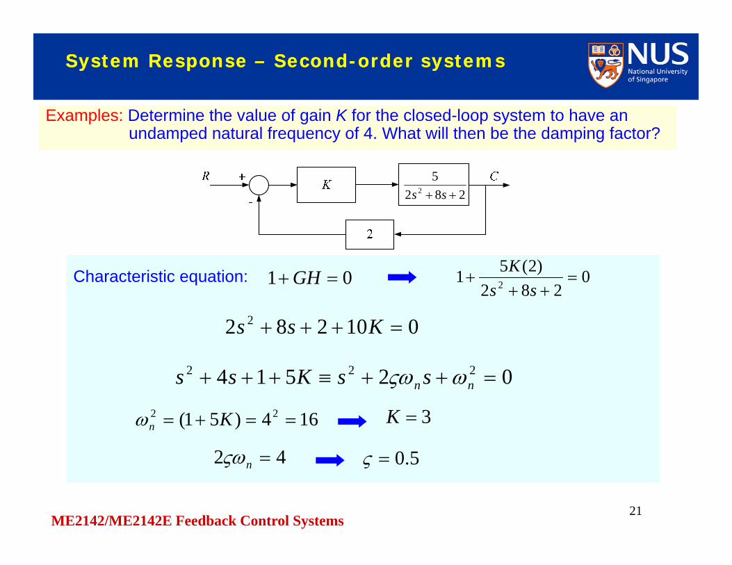
Characteristic equation: 01 GH 0282
)2(51 2
ss
K
21
Examples: Determine the value of gain K for the closed-loop system to have anundamped natural frequency of 4. What will then be the damping factor?
Examples: Determine the value of gain K for the closed-loop system to have anundamped natural frequency of 4. What will then be the damping factor?
System Response – Second-order systemsSystem Response – Second-order systems
2825
2 ss
010282 2 Kss
02514 222 nn ssKss
164)51( 22 Kn 3K
42 n 5.0

ME2142/ME2142E Feedback Control Systems
Transfer function: GHG
RC
1
22
Examples: Determine the value of gain K for the closed-loop system to have anundamped natural frequency of 4. What will then be the damping factor?
Examples: Determine the value of gain K for the closed-loop system to have anundamped natural frequency of 4. What will then be the damping factor?
System Response – Second-order systemsSystem Response – Second-order systems
2825
2 ss
164)51( 22 Kn 3K
42 n 5.0
KssK
102825
2
)51(45.2
2 KssK

ME2142/ME2142E Feedback Control Systems23
Consider Consider 22
2
2 nn
n
ssR
Time Response – Second-order systemsTime Response – Second-order systems
For , the roots are equal and the system is said to be critically damped.For , the roots are equal and the system is said to be critically damped.
1 np 2,1
The roots of the characteristic equation are
122,1 nnp
For , the roots are both real and unequal and the system is said to be overdamped.For , the roots are both real and unequal and the system is said to be overdamped.
1 122,1 nnp
For , the roots are a pair of complex conjugates10
where is called the damped natural frequency and the response is underdamped.
dn jp 2,1
21 nd
ME2142/ME2142E Feedback Control Systems24
Step Response – Second-order systemsStep Response – Second-order systems
Therefore
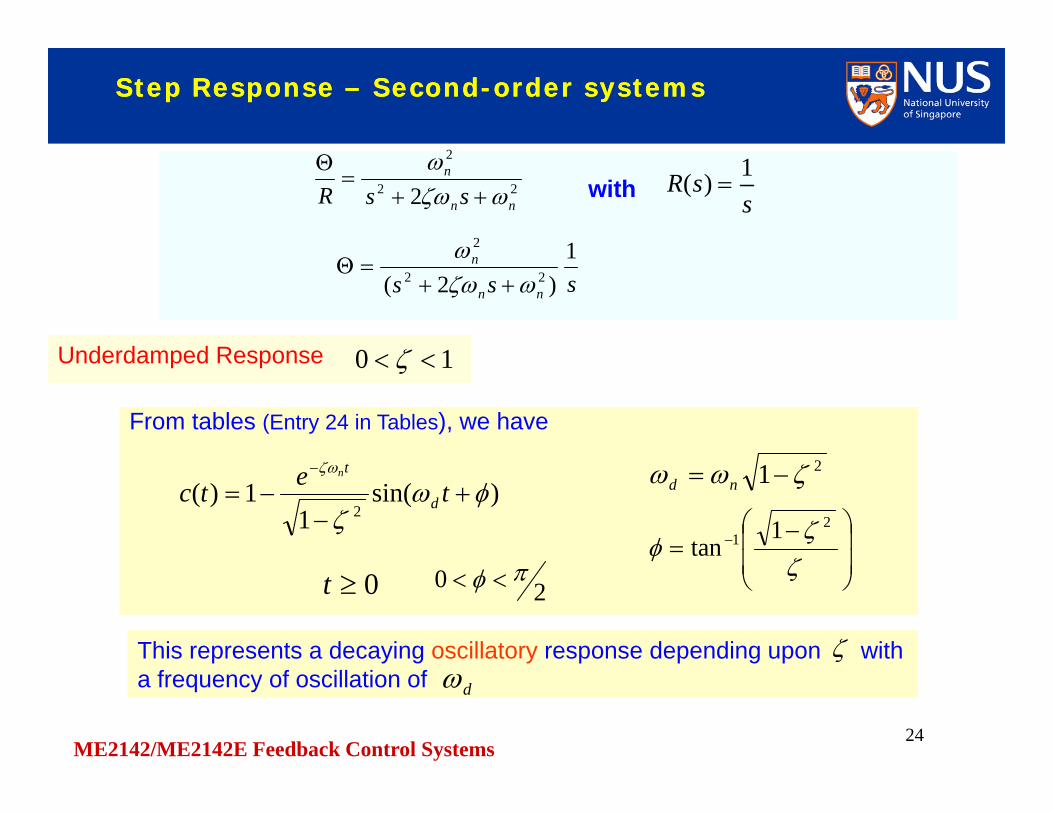
withwith ssR 1)( 22
2
2 nn
n
ssR
sss nn
n 1)2( 22
2
This represents a decaying oscillatory response depending upon with a frequency of oscillation of This represents a decaying oscillatory response depending upon with a frequency of oscillation of
Underdamped ResponseUnderdamped Response 10
d
From tables (Entry 24 in Tables), we haveFrom tables (Entry 24 in Tables), we have
)sin(1
1)(2
tetc d
tn
20 0t
2
1 1tan
21 nd
ME2142/ME2142E Feedback Control Systems
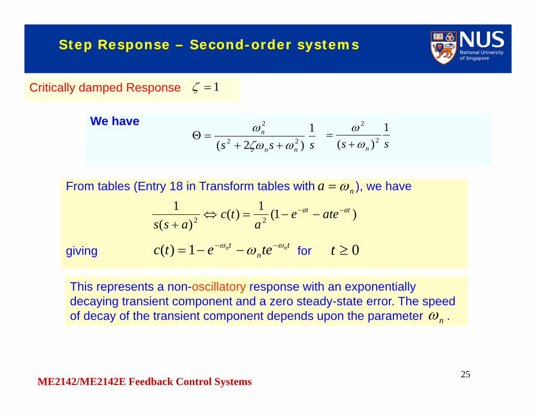
From tables (Entry 18 in Transform tables with ), we haveFrom tables (Entry 18 in Transform tables with ), we havena
)1(1)()(
122
atat ateea
tcass
25
Step Response – Second-order systemsStep Response – Second-order systems
We have We have
sss nn
n 1)2( 22
2
Critically damped ResponseCritically damped Response 1
ss n
1)( 2
2
This represents a non-oscillatory response with an exponentially decaying transient component and a zero steady-state error. The speed of decay of the transient component depends upon the parameter .
This represents a non-oscillatory response with an exponentially decaying transient component and a zero steady-state error. The speed of decay of the transient component depends upon the parameter .n
tn
t nn teetc 1)( 0tgiving for

ME2142/ME2142E Feedback Control Systems26
We use Entry 17 in Transform tables. We use Entry 17 in Transform tables.
Step Response – Second-order systemsStep Response – Second-order systems
sss nn
n 1)2( 22
2
Overdamped ResponseOverdamped Response 1
sss nnnn
n
)1)(1( 22
2
0t
btat eCeC 211
for , C1 and C2 being constants.
The response is non-oscillatory, starts initially with and exponentially rises to . The response is non-oscillatory, starts initially with and exponentially rises to .
0)0( c1)( c
If , then and the first exponential term will decay much faster than the second. The pole can then be neglected and the system behaves like a first-order system.
If , then and the first exponential term will decay much faster than the second. The pole can then be neglected and the system behaves like a first-order system.
ba 1)( as
))((
2
bsassn
12 nna 12 nnbwith and
2nab We have
)
2
(11)( btat aebebaab
tcn
so that

ME2142/ME2142E Feedback Control Systems27
Step Response – Second-order systemsStep Response – Second-order systems
Normalized response curves
For fast response,is usually
desirable.7.0
If no overshoot is required, is usually used.
1

ME2142/ME2142E Feedback Control Systems28
Transient Response SpecificationsTransient Response Specifications
Maximum (percent) overshoot:
%100)(
)()(
cctc
M pp
Delay time
Rise time:10% - 90%, or5% - 95%, or0% - 100%
Peak time
Settling time: time to reach and stay within specified limits, usually 2% or 5%.
Five measures of transient performance – based on 2nd-order underdamped responseFive measures of transient performance – based on 2nd-order underdamped response

ME2142/ME2142E Feedback Control Systems29
Measures of transient performanceMeasures of transient performance
We haveWe have
)sin(1
1)(2
tetc d
tn
2
1 1tan
1)( rtc giving 0)sin( rd t or 0 rd t
Thus rd t
2
1 1tan
2
1 1tan
Rise TimeRise Time rt
drt
giving
21 nd
ME2142/ME2142E Feedback Control Systems30
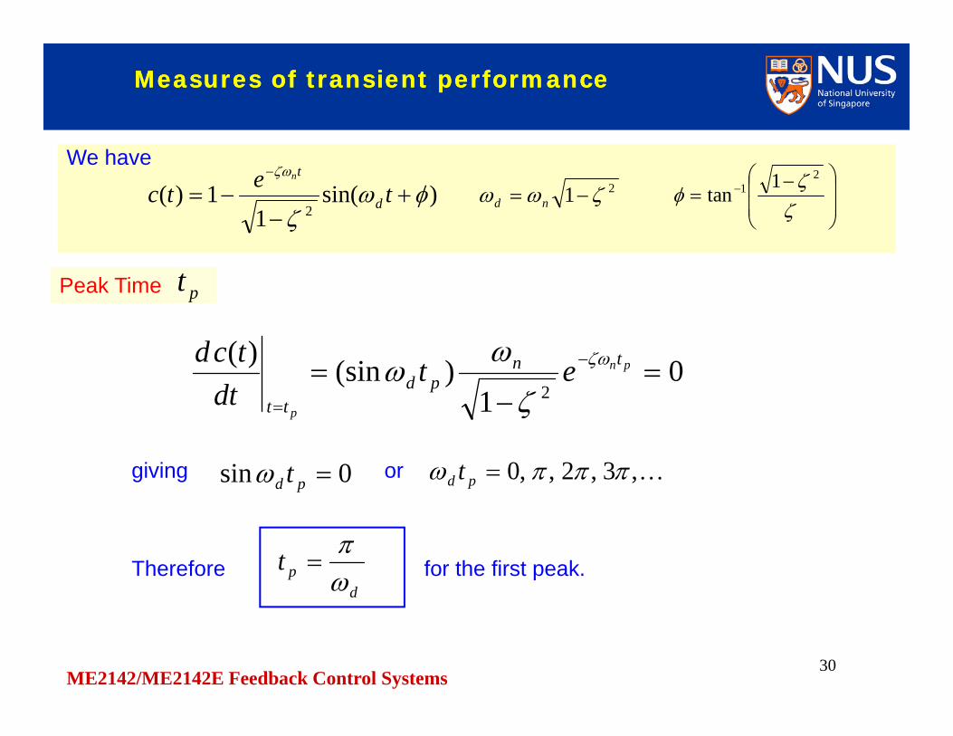
We haveWe have
)sin(1
1)(2
tetc d
tn
2
1 1tan
Peak TimePeak Time pt
21 nd
01
)(sin)(2
pn
p
tnpd
tt
etdt
tcd
giving 0sin pd t or ,3,2,,0 pd t
Therefore for the first peak. d
pt
Measures of transient performanceMeasures of transient performance

ME2142/ME2142E Feedback Control Systems31
We haveWe have
)sin(1
1)(2
tetc d
tn
2
1 1tan
Maximum OvershootMaximum Overshoot
21 nd
pM
1)( pp tcM
])/(sin[1 2
)/(
dd
dne
)sin(1 2
)1/( 2
e
As 21)sin(
Therefore )1/( 2 eM p
Measures of transient performanceMeasures of transient performance

ME2142/ME2142E Feedback Control Systems32
We haveWe have
)sin(1
1)(2
tetc d
tn
2
1 1tan
Settling TimeSettling Time
21 nd
st
The curves gives the
envelope curves of the transient response. )1/(1 2 tne
is found to be approximately
where “time constant”
st
Tts 4
Tts 3
(2% criterion)
(5% criterion)
n
T
1
Measures of transient performanceMeasures of transient performance

ME2142/ME2142E Feedback Control Systems33
End