systematic evaluation of biofilm models for - chaire modeleau
TRANSCRIPT

Systematic evaluation of biofilm models for engineering
practice: components and critical assumptions
J. P. Boltz, E. Morgenroth, D. Brockmann, C. Bott, W. J. Gellner
and P. A. Vanrolleghem
ABSTRACT
Biofilm models are valuable tools for the design and evaluation of biofilm-based processes despite
several uncertainties including the dynamics and rate of biofilm detachment, concentration gradients
external to the biofilm surface, and undefined biofilm reactor model calibration protocol. The present
investigation serves to (1) systematically evaluate critical biofilm model assumptions and
components and (2) conduct a sensitivity analysis with the aim of identifying parameter subsets for
biofilm reactor model calibration. AQUASIM was used to describe submerged-completely mixed
combined carbon oxidation and nitrification IFAS and MBBR systems, and tertiary nitrification and
denitrification MBBRs. The influence of uncertainties in model parameters on relevant model outputs
was determined for simulated scenarios by means of a local sensitivity analysis. To obtain
reasonable simulation results for partially penetrated biofilms that accumulated a substantial
thickness in the modelled biofilm reactor (e.g. 1,000 μm), an appropriate biofilm discretization was
applied to properly model soluble substrate concentration gradients and, consistent with the
assumed mechanism for describing biofilm biomass distribution, biofilm biomass spatial variability.
The MTBL thickness had a significant impact on model results for each of the modelled reactor
configurations. Further research is needed to develop a mathematical description (empirical or
otherwise) of the MTBL thickness that is relevant to modern biofilm reactors. No simple
recommendations for a generally applicable calibration protocol are provided, but sensitivity analysis
has been proven to be a powerful tool for the identification of highly sensitive parameter subsets for
biofilm (reactor) model calibration.
J. P. Boltz (corresponding author)CH2M HILL, Inc.,4350 W. Cypress Street, Suite 600,Tampa, FL 33607,USAE-mail: [email protected]
E. MorgenrothETH Zürich,Institute of Environmental Engineering,8093 Zürich,Switzerland
and
Eawag, Swiss Federal Institute of Aquatic Scienceand Technology,
8600 Dübendorf,Switzerland
D. BrockmannINRA, UR0050,Laboratoire de Biotechnologie de l’Environnement,Avenue des Etangs,Narbonne, F-11100,France
C. BottHampton Roads Sanitation District,1440 Air Rail, Ave.,Virginia Beach, VA 23455,USA
W. J. GellnerHazen and Sawyer,11311 Cornell Park Dr.,Cincinnati, OH 45242,USA
P. A. VanrolleghemCanada Research Chair in Water Quality Modelling,modelEAU,Université Laval, Pavillon Pouliot,Québec (QC),Canada G1K 7P4
Key words | AQUASIM, biofilm, calibration, design, identifiably, model, nitrogen removal, parameter,
wastewater
INTRODUCTION
A mathematical biofilm model has been included in amajority of available wastewater treatment plant simulators
that are used by practising engineers who seek to plan,evaluate, optimize, and/or design biofilm-based wastewatertreatment processes. Practice based biofilm reactormodellingapproaches typically use a one-dimensional (1-D) represen-
tation of the biofilm (see Wanner et al. () for details).While there is agreement that a 1-D biofilm model is suitable(for most applications) when describing biofilm reactor
performance, there are different modelling approaches
that require consideration (e.g. attachment/detachment,homogeneous vs. heterogeneous biomass distribution within
the biofilm, mass transfer resistance external to the biofilm,and diffusivity within the biofilm).
Modelling approaches requiring consideration
The lack of a generally accepted systematic calibration pro-
tocol for biofilm reactor models leads to uncertainty amongmodel users about how to best estimate model parameters
930 © IWA Publishing 2011 Water Science & Technology | 64.4 | 2011
doi: 10.2166/wst.2011.709

and calibrate biofilm models. Both aspects are discussed in
more detail below.Attachment and detachment processes: The rate at which
particles attach and detach from a biofilm has a marked
impact onmodelling results. In amodelling study,Morgenroth&Wilderer () demonstrated that overall reactor perform-ance and biofilm structure are significantly influenced by themode of detachment. However, both biofilm attachment and
detachment process mechanics are poorly understood; there-fore, approaches to modelling these processes may havelimited reliability and robustness when describing a biofilm
reactor. Most heterogeneous 1-D biofilm models used inengineering practice (see Boltz et al. (b) for a comprehen-sive list) describe the rate of particle attachment (rat) as a
first-order process that is dependent on an attachment ratecoefficient (kat), bulk-liquid particle concentration (Xi), andbiofilm area (AF). Given the current state of science, exper-imental data is required to evaluate existing models, and
develop and validate improved mathematical relationshipsdescribing the fate of particulate matter in biofilm reactors.
Steady-state biofilm models assume a constant biofilm
thickness (LF) and are applied under the premise that biofilmgrowth is balanced by a combination of internal loss (e.g.decay and hydrolysis, or endogenous respiration) and detach-
ment. Consequently, detachment may not be modelledexplicitly. However, the dynamic simulation of biofilms(and biofilm reactors) requires the inclusion of an explicit
detachment model despite rather limited mechanistic under-standing. Some rate expressions have been summarized byMorgenroth & Wilderer () and Morgenroth ().Rate expressions applied to practice-oriented models have
been summarized by Boltz et al. (b). The rate and cat-egory (i.e. abrasion, erosion, sloughing, and predatorgrazing) of detachment can have a significant influence on
biofilm structure and, therefore, reactor simulation and per-formance (Morgenroth ). Kissel et al. () stated thatproblems inherent to biofilm detachment modelling include
a poor understanding of fundamental (biofilm detachment)process mechanics and the inability to predict exactly atwhat location inside the biofilm that detachment will occur.
Biofilm detachment location is important when taking intoaccount the distribution of a heterogeneous biofilm through-out a reactor either by combining multiple 1-D simulations orby 2-D or 3-D modelling (Morgenroth et al. ).
Biofilm structure: Mixed-culture biofilms that develop incombined carbon oxidation and nitrification biofilm reac-tors may be generally characterized by the spatial
distribution of microorganisms throughout the biofilm.This spatial distribution is referred to as the biofilm structure
for the remainder of this paper. In these biofilms the faster
growing heterotrophic bacteria tend to exist predominantlyin biofilm locations near the bulk-liquid and biofilm inter-face. These heterotrophic bacteria overgrow autotrophic
nitrifiers and establish a stratified biofilm (perpendicular tothe growth medium) in which the nitrifiers exist deeperinside the biofilm (Zhang et al. ; Okabe et al. ). Asa result, heterotrophic bacteria have more direct access to
substrates and macronutrients diffusing from the bulkliquid into the biofilm, but the bacteria are also more suscep-tible to detachment from the biofilm surface. The
experimentally observed spatial distribution of hetero-trophic and autotrophic bacteria in a mixed-culture biofilmgrowing in a combined carbon oxidation and nitrification
biofilm reactor has been described by mathematicalmodels of biofilms (Kissel et al. ; Wanner & Gujer; Rittmann & Manem ). In heterogeneous 1-D bio-film models the observed spatial distribution of bacteria is
described as a series of layers, which also describes thespatial distribution of soluble substrates. A homogeneousbiofilm biomass distribution reduces the competitive advan-
tage of heterotrophic bacteria that exists in a heterogeneous(layered) 1-D biofilm model, as heterotrophic and auto-trophic bacteria are evenly distributed throughout the
biofilm and have direct access to both substrates and macro-nutrients diffusing from the bulk liquid into the biofilm. Ahomogeneous biofilm biomass distribution can be modelled
by introducing an artificial diffusion of all particulate com-pounds (Elenter et al. ). This approach allows using aseries of layers for describing substrate gradients withinthe biofilm while maintaining an even distribution of par-
ticulate compounds throughout the biofilm.External mass transfer boundary layer: Biofilms growing
in virtually all full-scale biofilm reactors are subject to some
degree of substrate concentration gradients external to thebiofilm surface (Lewandowski et al. ). Concentrationgradients external to the biofilm surface are not explicitly
simulated in 1-D biofilm models. Rather, the reduction inconcentration of any substrate is modelled as a mass-transferresistance, RL (¼LL/Daq). The external mass-transfer resist-
ance, RL, is primarily dependent on biofilm reactor bulk-liquid hydrodynamics; therefore, the impact of RL may beaccounted for by using empirical correlations (Wanneret al. () – see Table S4 in the supplemental material
hosted at http://www.iwaponline.com/wst/06404/0709.pdf).A realistic description of hydrodynamic effects is ultimatelydependent on an accurate estimate of the mass transfer
boundary layer (MTBL) thickness, LL. In addition, theMTBL is a mechanism that establishes a link between the
931 J. P. Boltz et al. | Systematic evaluation of biofilm models for engineering practice Water Science & Technology | 64.4 | 2011

1-D biofilm model and the bulk-phase compartment, and
allows the use of a 1-D biofilm model to describe a biofilmreactor. Therefore, LL is an important facet of biofilm-reac-tor models that may have a substantial impact on biofilm-
reactor model results and, consequently, process design.While observing a submerged fixed-bed nitrifying biofilmreactor, Zhu & Chen () observed an increase inammonium flux with a corresponding increase in Reynolds
number. The researchers described changes in ammoniumflux as a function of varying hydrodynamic conditionsby means of a mass transfer resistance external to the bio-
film – an increase in ammonium flux was associated witha decrease in the MTBL thickness. Brockmann et al.() had to adjust the MTBL thickness to fit experimental
data of a pilot-scale biofilm reactor for deammonification tomodel results using parameter values previously estimatedin laboratory-scale batch experiments.
Diffusivity coefficients. Soluble substrates are trans-
ported into biofilms by advection and molecular diffusion.Molecular diffusion is generally considered the dominantmechanism (Zhang & Bishop b). The effective diffusion
coefficient value varies for different solutes (Stewart ).Typically, the diffusivity of a solute inside the biofilm is lessthan that in water because of the tortuosity of the pores and
minimal biofilm permeability. Consequently, an effective dif-fusivity must be applied when using a mathematical biofilmmodel. Commonly, a value that is 80% of the solute’s diffusiv-
ity in water (i.e. Daq¼DF/0.8) is applied when modellingbiofilm reactors (Wanner et al. ). Several studies haveshown that diffusivity inside the biofilm decreases with bio-film depth (Zhang & Bishop b; Beyenal et al. ;
Beyenal & Lewandowski ). Decreasing diffusivity withincreasing biofilm depth can be attributed to increasing den-sity, decreasing porosity, and decreasing permeability with
depth (Zhang & Bishop a, b). Despite variability in theeffective diffusion coefficient value, a single and constanteffective diffusion coefficient value is typically used for
each solute considered in biofilm models to reduce modelcomplexity.
Parameter estimation and model calibration
Parameter estimation is a serious concern for practitionerswho seek to use steady-state and/or dynamic biofilm
models to describe biofilm-based processes in full-scalemunicipal wastewater treatment plants because most par-ameter values cannot be measured directly in full-scale
treatment facilities (Brockmann et al. ). In addition tostoichiometric and biokinetic parameters also used in
activated sludge models, parameters exist for describing
external and internal mass transfer as well as the biofilmitself. A majority of parameter values in modern processmodels (e.g. those described by Henze et al. ) have a sub-
stantial database that serves to define a relatively narrowrange of values that are applicable to a majority of municipalwastewater treatment systems (see Hauduc et al. ). Exist-ing biofilm models are relatively insensitive to changes in a
majority of the biokinetic parameter values described byHenze et al. () within the range of reported values. How-ever, exceptions exist. In some cases, the mathematical
description of processes consists of variable, or lumped, par-ameters. These parameter values are often system specificand subject to significant uncertainty, and account for an
incomplete mechanistic description of the simulated process.Systematic identification of parameter subsets that
require definition for biofilm model calibration has been thesubject of recent investigations by Smets et al. (), VanHulle et al. (), and Brockmann et al. (). In contrast,Sin et al. () and Bilyk et al. () used ad hoc expert-based trial and error approaches to calibrate biofilm process
models by manipulating system specific parameters relatedto attachment, detachment, and biofilm thickness (Sin et al.) or by adjusting the ‘assumed biofilm thickness’ and
incorporating an assimilative denitrification reaction (Bilyket al. ). All identification and biofilm reactor model cali-bration efforts were based on bulk-phase measurements, but
only Sin et al. () used measured characteristics of thebiofilm. Such adjustments to system specific biofilm and bio-kinetic parameters in order to match observed data may notproduce a properly calibratedmodel that is capable of describ-
ing a variety of design conditions for aWWTP. Suffice it to saythat a reliable and transparent description of recommendedapproaches for the application and calibration of biofilm
models is required for the models to gain general acceptanceand understanding, and be subject to consistent effective usein engineering design. Protocol defining methodology for
sampling, testing, evaluating and applying data to mathemat-ical biofilm reactor models is required. Such systematiccalibration protocol exists for activated sludge models. Sin
et al. () presented a critical comparison of different cali-bration protocols. These protocols have many similaritiesthat are applicable to biofilm reactor models includinggoal definition, data collection/verification/reconciliation,
and validation. The major differences between the protocolsreported by Sin et al. () are related to the samplemeasure-ment campaign, influent wastewater characterization test
methodology, and parameter subset selection and calibra-tion. These are areas of the existing systematic calibration
932 J. P. Boltz et al. | Systematic evaluation of biofilm models for engineering practice Water Science & Technology | 64.4 | 2011

protocols that will almost certainly be aggravated when creat-
ing a systematic protocol for the calibration of biofilm reactormodels. When compared to a suspended growth reactor,additional tests will certainly be required to characterize the
physical attributes of a systemhaving both suspended biomassand biofilm compartments. In addition, mathematical biofilmmodels have more parameters than activated sludge processmodels. In order to have a timely and cost effective systematic
approach to calibrating biofilm models, parameters related tothe biofilm compartment must be estimated from bulk-phasemeasurements.
The goal of this paper is to present (1) a systematicevaluation of biofilm model components and criticalassumptions, and (2) a local sensitivity analysis with the
aim of identifying parameter subsets for biofilm reactormodel calibration. The influence of factors such as biofilmthickness, organism distribution over the thickness of thebiofilm, MTBL thickness, the effect of mixing conditions
(completely mixed vs. plug-flow conditions), wastewatertemperature, diffusion coefficients, and biokinetic parameterswere evaluated using the simulation software AQUASIM.
MATERIAL AND METHODS
Biofilm and kinetic model
A 1-D biofilm model was implemented using AQUASIM(Reichert ). The modelling study included state variablesdescribing soluble (S) and particulate (X ) matter. The pro-cess, kinetic, and stoichiometric model was based on
Activated Sludge Model No. 3 (ASM3) as described byHenze et al. (), but storage of readily biodegradable sub-strate was not modelled. Two types of methanol degrading
heterotrophic organisms (XM1 and XM2) were included inthe model to describe tertiary denitrification using methanolas the supplemental carbon source. A complete list of state
variables, stoichiometric parameters, kinetic parameters, bio-film parameters, and transformation rate expressions arelisted in Tables S1–S5 in the supplemental material (http://
www.iwaponline.com/wst/06404/0709.pdf). Biofilmdetach-ment wasmodelled using two different approaches: (1) a userdefined (fixed) biofilm thickness that is maintained by balan-cing growth and loss, and (2) using two functions describing
the rate of detachment (rdet,1¼ kdet · LF and rdet,2¼ kdet · LF2).
Both modelling approaches maintained a constant biofilmthickness, LF. The rate of biofilm detachment may change
depending on the assumed biofilm biomass distributionsince the rate of growth and loss (in this case by endogenous
respiration) is dependent on local substrate availability and
environmental conditions. Biofilm fragments were assumedto detach from the biofilm surface; therefore, preferentialdetachment is considered for the heterogeneous (layered) bio-
film biomass distribution (i.e. bacteria growing at the biofilm–
liquid interface detach from the biofilm surface and enter thebulk of the liquid). Substrate concentration gradients externalto thebiofilmweremodelledas amass transfer resistanceusing
the concept of aMTBLwith thickness LL. Results reported forall but one of themodels describe partially penetrated biofilms(i.e. the rate-limiting substrate is exhausted before reaching the
growth medium; therefore, the biofilm is not biomass limited).The tertiary nitrification MBBR (with a biofilm thicknessof 67 μm) was biomass limited, or completely penetrated.
Simulations
Municipal wastewater treatment scenarios that are com-monly the subject of full-scale process design and evaluationwere modelled including combined carbon oxidation andnitrification, tertiary nitrification, and tertiary denitrification.
The submerged, completely mixed biofilm reactors aredescribed as continuous flow stirred tank reactors (CFSTRs)analogous to moving bed biofilm reactors (MBBRs). In
addition, an integrated fixed film activated sludge (IFAS) pro-cess for combined carbon oxidation and nitrification wasmodelled. Influent wastewater characteristics and reactor
configurations are defined inTable 1. The influentwastewatercharacteristics were developed based on selected referencesand authors’ experience with the simulation and design ofthese processes. The influent wastewater flow rate for each
case modelled was 35,000 m3/d. Reactor configurationswere defined based on (1) design criteria presented by Boltzet al. (a) and McQuarrie & Boltz (), describing com-
bined carbon oxidation and nitrification MBBR, tertiarynitrification MBBR, and tertiary denitrification MBBR, and(2) a requirement that less than 1 mg methanol/L remained
in the tertiary denitrificationMBBR effluent stream. IFAS pro-cess designwas created basedonauthor experience,which hasbeen presented to a certain extent by Kim et al. (). Steady-state simulations were run for 20 WC unless otherwise stated, arepresentative annual average day temperature.
Table 2 provides a summary of the different modellingscenarios used to quantify the impact of changes in biofilm
thickness, biofilm structure, MTBL thickness, mixingconditions, temperature, and model parameter values in gen-eral. A homogeneous biofilm structure was modelled by
introducing an artificial diffusion coefficient of all particulatecompounds (Elenter et al. ). The value of the diffusion
933 J. P. Boltz et al. | Systematic evaluation of biofilm models for engineering practice Water Science & Technology | 64.4 | 2011

coefficient for particulate compounds was assigned a greatenough value to guarantee that no significant gradient for
these particulate compounds could develop over the biofilmthickness. The influence of parameter values (scenario VI)was analysed based on local sensitivity analyses at 20 and
12 WC.The local sensitivity analysis approachused is describedin more detail below.
Local sensitivity analysis
Model sensitivity to changes in biokinetic and biofilm par-ameter values was evaluated for steady state and discussed
with emphasis given to identifying the parameters thatmay have a negligible impact on model results when adjust-
ing the values within a range reported in the literature.Parameter values that may vary from system to system treat-ing municipal wastewater (e.g. KO2,A, LF) are identified and
the impact of changes in their values (again within a rangeof values reported in the literature) is evaluated. Althoughparameter values may vary considerably, model sensitivity
was not evaluated based on a global sensitivity analysis asdescribed in Brockmann et al. (), but on a simplerlocal sensitivity analysis. While the global sensitivity analy-sis accounts for non-linear model outcomes within the
Table 1 | Reactor configurations and wastewater characteristics for the simulated municipal wastewater treatment scenarios
Configurations
(A) MBBR Combined carbonoxidation and nitrification
(B) MBBR Tertiarynitrification
(C) MBBR Tertiarydenitrification
(D) IFAS Combined carbonoxidation and nitrification
Reactor configuration
Reactor volume (m3) 5,000 2,200 1,400 2,200
Biofilm surface area (m2) 1,250,000 550,000 350,000 550,000
Bulk phase DO (mg O2/L) 4.0 5.0 0.0 4.0
Influent flow rate (m3/d) 35,000 35,000 35,000 35,000
Wastewater characteristics
SS (g COD/m3) 89.0 5.7 1.1 40.0
SM (g COD/m3) – – 15.0 –
SI (g COD/m3) 13.3 18.7 18.7 13.3
SNH4 (g N/m3) 26.0 22.5 2.0 26.0
SNO3 (g N/m3)) 0.7 1.4 5.1 0.7
SALK (mol HCO3�/m3) 4.8 5.0 4.1 4.8
XS (g COD/m3) 250.0 0.2 8.3 250.0
XI (g COD/m3) 69.3 2.1 2.1 69.3
Table 2 | Modelling scenarios (base scenario settings are underlined)
Scenarios Parameter Values evaluated
I Biofilm thickness, LF Fixed thickness (200 μm) Deep biofilm (2,000 μm) LF resulting from different detachmentrate functions
II Biofilm structure Heterogeneous (layered) Homogeneous
III MTBL thickness, LL LL = 100 μm LL¼ 0 μm LL¼ Lc/Sha
IV Reactors-in-series N= 1 N¼ 3 N¼ 6
V Temperature 20 ˚C 12 WC
VI Parameter values From Table S9 in the Appendix (Sensitivity analysis)
aMass transfer boundary layer (MTBL) thickness LL calculated for each soluble substance individually with Lc being the characteristic length and Sh the Sherwood number (for details see
Appendix S4 in the Supplemental Material http://www.iwaponline.com/wst/06404/0709.pdf).
934 J. P. Boltz et al. | Systematic evaluation of biofilm models for engineering practice Water Science & Technology | 64.4 | 2011

defined uncertainty ranges of the parameters, the local sen-
sitivity analysis linearly extrapolates the impact of a smallchange in the parameter value to the uncertainty range ofthe parameter. Local sensitivity analyses were carried out
for the base scenario altering the parameters in incrementalsteps defined by 1% of their default value. A sensitivitymeasure δ was calculated from scaled sensitivity valuesthat include information on a reasonable range (i.e. the
uncertainty range) of the parameters (Brun et al. ):
δ ¼ffiffiffiffiffiffiffiffiffiffiffiffiffiffiffiffiffi1n
Xni¼1
s2i;j
vuut with si;j ¼Δpjsci
� @yi@pj
where Δpj represents the uncertainty range of the parameterpj, sci is a scale factor, and n is the number of model outputsconsidered. A large δ means that a change of Δpj in par-
ameter pj has a substantial impact on the consideredmodel output(s). Model parameters were assigned to threeuncertainty classes according to Brun et al. (). In thisstudy, sensitivity analyses were only carried out for par-
ameters from uncertainty classes 2 and 3. Parameters fromuncertainty class 1 were not considered for sensitivity analy-sis due to their low uncertainty (or 5% of the default
parameter value) when compared to uncertainty classes 2and 3. The uncertainty range of parameters from uncertaintyclass 2 is 20% of the default parameter value, and 50% for
parameters from uncertainty class 3. Studied parametersand their uncertainty ranges are given as supplementalmaterial http://www.iwaponline.com/wst/06404/0709.pdf.
RESULTS AND DISCUSSION
Benchmark simulations
The influence of biofilm thickness (scenario I), biofilm
structure (scenario II), MTBL thickness (scenario III),mixing conditions (scenario IV), temperature (scenarioV), and specific parameter values (scenario VI) were eval-
uated, as summarized in Table 2, for the different reactorconfigurations described in Table 1. Table 3 lists resultsfor the combined carbon oxidation and nitrificationMBBR simulations (i.e., configuration A), Table 4 lists
results from tertiary nitrification MBBR simulations (i.e.configuration B), Table 5 lists results from tertiarydenitrification MBBR simulations (i.e. configuration C),
and Table 6 lists results from IFAS process simulations(i.e. configuration D).
Biofilm thickness (scenario I): Model results obtained
from simulating a submerged and completely mixed com-bined carbon oxidation and nitrification biofilm reactor(e.g. the MBBR described as configuration A in Table 3)
indicated that the nitrate (SNO3) and slowly biodegradableorganic matter (XS) concentrations remaining in the effluentstream were less when the biofilm was thicker (e.g. LF¼2,000 μm). In contrast, the readily biodegradable organic
matter (SS), ammonium (SNH4), and di-nitrogen (SN2) con-centrations remaining in the effluent stream were lesswhen the biofilm was thinner (e.g. LF¼ 200 μm). As the
bulk-liquid SNO3 and SN2 concentrations are a measure ofdenitrification, it follows that denitrification rates weregreater when the biofilm was thicker. In systems with thin-
ner biofilms (e.g. LF¼ 200 μm), denitrification wasinhibited by the presence of oxygen, or limited by the avail-ability of substrate or biomass. In addition, the hydrolysis ofXS to SS was limited by the available mass of non-methanol
degrading heterotrophic bacteria (XH) in thinner biofilms(e.g. LF¼ 200 μm). Thus, the biofilm thickness had animpact on denitrification in the biofilm and the extent of
hydrolysis. Greater SS and SNH4 concentrations remainingin the effluent stream of the simulated MBBR with thickerbiofilms (e.g. LF¼ 2,000 μm) resulted from increased
hydrolysis of XS to SS and dissolved oxygen limited aerobicconversion processes. Bulk-liquid substrate concentrationsand substrate fluxes did not vary with biofilm thickness
according to the tertiary nitrification and tertiary denitrifica-tion MBBR model results (as described by configurations Band C) (see Tables 4 and 5). The model results are in agree-ment with experimental observations reported by others.
Okabe et al. () observed for an autotrophic nitrifyingbiofilm that dissolved oxygen diffusing into the biofilm wasdepleted approximately 150 μm from the biofilm surface,
ammonium and nitrite were both converted to nitratewithin 100 μm of the biofilm surface, and ammonia oxidiz-ing bacteria (AOB) and nitrite oxidizing bacteria (NOB)
were densely present inside 100 μm (from the liquid–biofilminterface). Similarly, Schramm et al. () observed densepopulations of AOB and NOB in the upper and aerobic
100 μm (from the liquid–biofilm interface) of a nitrifying bio-film. Horn & Hempel () observed for both autotrophicand heterotrophic biofilms that oxygen was depletedwithin 100–200 μm of the liquid–biofilm interface. There-
fore, it may be deduced that for aerobic conversionprocesses, such as nitrification, biofilm thicknesses greaterthan approximately 200 μm do not influence substrate con-
centrations (remaining in the effluent stream) andsubstrate fluxes as only the upper aerobic part of the biofilm
935 J. P. Boltz et al. | Systematic evaluation of biofilm models for engineering practice Water Science & Technology | 64.4 | 2011
will substantially contribute to the conversion processes.
However, when aerobic and anoxic conversion processesare desirable in the same biofilm, biofilm thickness has a dis-tinct impact on substrate concentrations (remaining in the
effluent stream) and substrate fluxes. In thin, yet partiallypenetrated, biofilms (e.g. LF< 100–200 μm), primarilyaerobic conditions will prevail where thicker biofilms (e.g.
LF> 200 μm) are able to sustain the development of bothaerobic and anoxic zones. Therefore, if simultaneous nitrifi-cation and denitrification are desired in a single-stagebiofilm reactor then the reactor should be operated in a
manner that promotes the development of thicker biofilms(e.g. LF> 200 μm). In contrast, if a low ammonium concen-tration (remaining in the effluent stream) is desired, then
operating conditions that promote the development of thinbiofilms (e.g. LF< 100–200 μm) are desirable to ensure thatbiofilm surface area and dissolved oxygen penetration
inside the biofilm are simultaneously maximized.
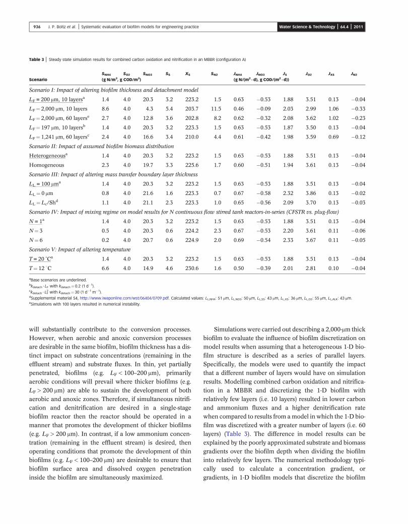
Simulations were carried out describing a 2,000-μm thick
biofilm to evaluate the influence of biofilm discretization onmodel results when assuming that a heterogeneous 1-D bio-film structure is described as a series of parallel layers.
Specifically, the models were used to quantify the impactthat a different number of layers would have on simulationresults. Modelling combined carbon oxidation and nitrifica-
tion in a MBBR and discretizing the 1-D biofilm withrelatively few layers (i.e. 10 layers) resulted in lower carbonand ammonium fluxes and a higher denitrification ratewhen compared to results from amodel in which the 1-D bio-
film was discretized with a greater number of layers (i.e. 60layers) (Table 3). The difference in model results can beexplained by the poorly approximated substrate and biomass
gradients over the biofilm depth when dividing the biofilminto relatively few layers. The numerical methodology typi-cally used to calculate a concentration gradient, or
gradients, in 1-D biofilm models that discretize the biofilm
Table 3 | Steady state simulation results for combined carbon oxidation and nitrification in an MBBR (configuration A)
SNH4 SO2 SNO3 SS XS SN2 JNH4 JNO3 JS JO2 JXS JN2
Scenario (g N/m3, g COD/m3) (g N/(m2 · d), g COD/(m2 · d))
Scenario I: Impact of altering biofilm thickness and detachment model
LF = 200 μm, 10 layersa 1.4 4.0 20.3 3.2 223.2 1.5 0.63 �0.53 1.88 3.51 0.13 �0.04
LF¼ 2,000 μm, 10 layers 8.6 4.0 4.3 5.4 203.7 11.5 0.46 �0.09 2.03 2.99 1.06 �0.33
LF¼ 2,000 μm, 60 layerse 2.7 4.0 12.8 3.6 202.8 8.2 0.62 �0.32 2.08 3.62 1.02 �0.23
LF¼ 197 μm, 10 layersb 1.4 4.0 20.3 3.2 223.3 1.5 0.63 �0.53 1.87 3.50 0.13 �0.04
LF¼ 1,241 μm, 60 layersc 2.4 4.0 16.6 3.4 210.0 4.4 0.61 �0.42 1.98 3.59 0.69 �0.12
Scenario II: Impact of assumed biofilm biomass distribution
Heterogeneousa 1.4 4.0 20.3 3.2 223.2 1.5 0.63 �0.53 1.88 3.51 0.13 �0.04
Homogeneous 2.3 4.0 19.7 3.3 225.6 1.7 0.60 �0.51 1.94 3.61 0.13 �0.04
Scenario III: Impact of altering mass transfer boundary layer thickness
LL = 100 μma 1.4 4.0 20.3 3.2 223.2 1.5 0.63 �0.53 1.88 3.51 0.13 �0.04
LL¼ 0 μm 0.8 4.0 21.6 1.6 223.3 0.7 0.67 �0.58 2.32 3.86 0.13 �0.02
LL¼ Lc/Shd 1.1 4.0 21.1 2.3 223.3 1.0 0.65 �0.56 2.09 3.70 0.13 �0.03
Scenario IV: Impact of mixing regime on model results for N continuous flow stirred tank reactors-in-series (CFSTR vs. plug-flow)
N= 1a 1.4 4.0 20.3 3.2 223.2 1.5 0.63 �0.53 1.88 3.51 0.13 �0.04
N¼ 3 0.5 4.0 20.3 0.6 224.2 2.3 0.67 �0.53 2.20 3.61 0.11 �0.06
N¼ 6 0.2 4.0 20.7 0.6 224.9 2.0 0.69 �0.54 2.33 3.67 0.11 �0.05
Scenario V: Impact of altering temperature
T= 20 ˚Ca 1.4 4.0 20.3 3.2 223.2 1.5 0.63 �0.53 1.88 3.51 0.13 �0.04
T¼ 12 WC 6.6 4.0 14.9 4.6 230.6 1.6 0.50 �0.39 2.01 2.81 0.10 �0.04
aBase scenarios are underlined.bkdetach · LF with kdetach¼ 0.2 (1 d�1).ckdetach · LF
2 with kdetach¼ 30 (1 d�1 m�1).dSupplemental material S4, http://www.iwaponline.com/wst/06404/0709.pdf. Calculated values: LL,NH4: 51 μm, LL,NO3: 50 μm, LL,SS: 43 μm, LL,XS: 36 μm, LL,O2: 55 μm, LL,ALK: 43 μm.eSimulations with 100 layers resulted in numerical instability.
936 J. P. Boltz et al. | Systematic evaluation of biofilm models for engineering practice Water Science & Technology | 64.4 | 2011

into a series of layers (having an equal thickness) results in astraight line between the midpoints of each layer. As such,consider an extreme in which a 1-D biofilm model consists
of only one layer. The concentration profile would be astraight line, which differs substantially from the curvedreduction typical of biofilms. Therefore, when simulating
thick mixed-culture biofilms with a low discretization (e.g.1,000-μm thick biofilm with 10 layers resulting in 100-μmthick layers), the user must be aware that the biofilm model
will likely not properly reflect substrate and, consequently,biomass gradients in the biofilm, and accurate system simu-lations will not result. Discussions held during theWWTmod 2010 (Monte Sainte Anne, Canada) biofilm mod-
elling workshop suggested that it was a typical practice of‘industry’ professionals to decrease the number of layers(e.g. to three to five) when modelling a heterogeneous 1-D
biofilm. Generally, this measure was taken to reduce simu-lation time. As demonstrated with the series of layers (in
this study having equal thickness) approach and supportingmodel results presented in this paper, the use of too fewlayers may impair such a model’s ability to generate accurate
results. The following section on biofilm structure describesconditions in which the loss of spatial resolution will infact impair model ability to generate accurate results.
After comparing model results no significant variation inbulk-liquid substrate concentrations or material fluxes wereobserved from the two different biofilm detachmentmodelling
approaches that were applied in this study. Both modellingapproaches maintained a constant biofilm thickness, LF.The rate of detachment changed depending on the assumedbiofilm biomass distribution since the rate of growth and loss
(in this case by endogenous respiration) is dependent onlocal substrate availability and environmental conditions.Model results can be reviewed for the combined carbon oxi-
dation and nitrification MBBR, tertiary nitrification MBBR,and tertiary denitrification MBBR in Tables 3–5, respectively.
Table 4 | Steady state simulation results for tertiary nitrification in an MBBR (configuration B)
SNH4 SO2 SNO3 SS XS SN2 JNH4 JNO3 JS JO2 JXS JN2
Scenario (g N/m3, g COD/m3) (g N/(m2 · d), g COD/(m2 · d))
Scenario I: Impact of altering biofilm thickness and detachment model
LF = 200 μm, 10 layersa 1.9 5.0 21.4 0.7 7.8 0.3 1.29 �1.25 0.32 5.79 0.00 �0.02
LF¼ 2,000 μm, 10 layers, actual LF 864 μm 2.6 5.0 20.5 0.8 7.6 0.5 1.26 �1.21 0.32 5.65 0.02 �0.03
LF¼ 2,000 μm, 100 layers, actual LF 877 μm 1.9 5.0 21.4 0.7 7.6 0.3 1.29 �1.25 0.32 5.80 0.02 �0.02
LF¼ 67 μm, 10 layersb 2.1 5.0 21.3 0.7 7.8 0.1 1.27 �1.24 0.32 5.67 0.00 �0.01
LF¼ 622 μm, 30 layersc 1.9 5.0 21.4 0.7 7.7 0.3 1.29 �1.25 0.32 5.80 0.01 �0.02
Scenario II: Impact of assumed biofilm biomass distribution
Heterogeneousa 1.9 5.0 21.4 0.7 7.8 0.3 1.29 �1.25 0.32 5.79 0.00 �0.02
Homogeneous 1.9 5.0 21.0 0.7 7.8 0.7 1.29 �1.23 0.32 5.80 0.00 �0.05
Scenario III: Impact of altering mass transfer boundary layer thickness
LL = 100 μma 1.9 5.0 21.4 0.7 7.8 0.3 1.29 �1.25 0.32 5.79 0.00 �0.02
LL¼ 0 μm 0.8 5.0 22.7 0.4 7.8 0.1 1.36 �1.34 0.35 6.19 0.00 �0.01
LL¼ Lc/Shd 1.3 5.0 22.2 0.6 7.8 0.2 1.33 �1.30 0.34 6.03 0.00 �0.01
Scenario IV: Impact of mixing regime on model results for N continuous flow stirred tank reactors-in-series (CFSTR vs. plug-flow)
N= 1a 1.9 5.0 21.4 0.7 7.8 0.3 1.29 �1.25 0.32 5.79 0.00 �0.02
N¼ 3 1.0 5.0 22.2 0.3 7.7 0.5 1.35 �1.30 0.35 6.01 0.00 �0.03
N¼ 6 0.5 5.0 22.5 0.2 7.7 0.5 1.38 �1.33 0.36 6.12 0.00 �0.03
Scenario V: Impact of altering temperature
T= 20 ˚Ca 1.9 5.0 21.4 0.7 7.8 0.3 1.29 �1.25 0.32 5.79 0.00 �0.02
T¼ 12 WC 6.1 5.0 17.2 0.9 7.9 0.3 1.03 �0.99 0.31 4.59 0.00 �0.02
aBase scenarios are underlined.bkdetach · LF.ckdetach · LF
2.dSupplemental material S4, http://www.iwaponline.com/wst/06404/0709.pdf. Calculated values: LL,NH4: 51 μm, LL,NO3: 50 μm, LL,SS: 43 μm, LL,XS: 36 μm, LL,O2: 55 μm, LL,ALK: 43 μm.
937 J. P. Boltz et al. | Systematic evaluation of biofilm models for engineering practice Water Science & Technology | 64.4 | 2011

Biofilm structure (scenario II): Simulation of combined
carbon oxidation and nitrification in mixed-culture biofilms(configuration A) assuming a homogeneous biofilm biomass
distribution resulted in significantly different simulation
results for effluent SNH4, while all other concentrations pre-dicted by the model, including ammonium flux, were not
Table 5 | Steady state simulation results for tertiary denitrification with methanol in an MBBR (configuration C)
SNH4 SNO3 SS SM XS SN2 JNH4 JNO3 JS JM JXS JN2
Scenario (g N/m3, g COD/m3) (g N/(m2 · d), g COD/(m2 · d))
Scenario I: Impact of altering biofilm thickness and detachment model
LF = 200 μm, 10 layersa 1.6 2.0 0.3 1.4 0.2 3.1 0.04 0.30 0.08 1.33 0.00 �0.30
LF¼ 2,000 μm, 10 layers 1.7 1.9 0.3 1.6 0.2 3.2 0.04 0.35 0.08 1.45 0.00 �0.35
LF¼ 2,000 μm, 100 layers 1.6 1.8 0.2 0.6 0.2 3.3 0.04 0.33 0.09 1.43 0.00 �0.33
LF¼ 110 μm, 10 layersb 1.6 2.0 0.3 1.4 0.2 3.1 0.04 0.30 0.08 1.32 0.00 �0.30
LF¼ 848 μm, 40 layersc 1.6 2.0 0.3 1.4 0.2 3.1 0.04 0.30 0.08 1.33 0.00 �0.30
Scenario II: Impact of assumed biofilm biomass distribution
Heterogeneousa 1.6 2.0 0.3 1.4 0.2 3.1 0.04 0.30 0.08 1.33 0.00 �0.30
Homogeneous 1.6 1.9 0.3 1.4 0.2 3.2 0.03 0.31 0.07 1.33 0.00 �0.31
Scenario III: Impact of altering mass transfer boundary layer thickness
LL = 100 μma 1.6 2.0 0.3 1.4 0.2 3.1 0.04 0.30 0.08 1.33 0.00 �0.30
LL¼ 0 μm 1.6 1.8 0.2 0.5 0.2 3.3 0.04 0.32 0.08 1.42 0.00 �0.32
LL¼ Lc/Shd 1.6 1.9 0.3 1.0 0.2 3.2 0.04 0.31 0.08 1.37 0.00 �0.31
Scenario IV: Impact of mixing regime on model results for N continuous flow stirred tank reactors-in-series (CFSTR vs. plug-flow)
N= 1a 1.6 2.0 0.3 1.4 0.2 3.1 0.04 0.30 0.08 1.33 0.00 �0.30
N¼ 3 1.6 1.8 0.2 0.2 0.2 3.3 0.04 0.33 0.09 1.45 0.00 �0.33
N¼ 6 1.6 1.8 0.1 0.0 0.2 3.4 0.04 0.33 0.09 1.47 0.00 �0.33
Scenario V: Impact of altering temperature
T= 20 ˚Ca 1.6 2.0 0.3 1.4 0.2 3.1 0.04 0.30 0.08 1.33 0.00 �0.30
T¼ 12 WC 1.7 2.1 0.4 2.1 0.2 3.0 0.03 0.29 0.07 1.27 0.00 �0.29
aBase scenarios are underlined.bkdetach · LF.ckdetach · LF
2.dSupplemental material S4, http://www.iwaponline.com/wst/06404/0709.pdf. Calculated values: LL,NH4: 51 μm, LL,NO3: 50 μm, LL,SS: 43 μm, LL,XS: 36 μm, LL,O2: 55 μm, LL,ALK: 43 μm.
Table 6 | Steady state simulation results for carbon oxidation and nitrification in the IFAS (configuration D)
Scenario SNH4 SO2 SNO3 SS XS SN2 JNH4 JNO3 JS JO2 JXS JN2
(g N/m3, g COD/m3) (g N/(m2 · d), g COD/(m2 · d))
Scenario III: Impact of altering mass transfer boundary layer thickness
LL = 100 μma 2.4 4.0 22.7 0.4 220.2 0.4 1.02 �1.00 0.06 4.44 0.02 0.00
LL¼ 0 μm 1.5 4.0 23.6 0.4 220.3 0.4 1.21 �1.18 0.42 5.44 0.04 0.00
LL¼ Lc/Shb 1.8 4.0 23.2 0.4 220.2 0.4 1.14 �1.12 0.13 5.00 0.03 0.00
Scenario V: Impact of altering temperature
T= 20 ˚Ca 2.4 4.0 22.7 0.4 220.2 0.4 1.02 �1.00 0.06 4.44 0.02 0.00
T¼ 12 WC 19.1 4.0 6.1 0.7 229.3 0.3 0.21 �0.20 0.12 0.95 0.01 0.00
aBase scenarios are underlined.bSupplemental material S4, http://www.iwaponline.com/wst/06404/0709.pdf. Values: LL,NH4: 51 μm, LL,NO3: 50 μm, LL,SS: 43 μm, LL,XS: 36 μm, LL,O2: 55 μm, LL,ALK: 43 μm.
938 J. P. Boltz et al. | Systematic evaluation of biofilm models for engineering practice Water Science & Technology | 64.4 | 2011

significantly affected when compared to simulation results
from a model that assumed a heterogeneous biofilm biomassdistribution (Table 3). In contrast, the biofilm biomass distri-bution did not affect simulation results in a submerged and
completely mixed biofilm reactor such as a tertiary nitrifica-tion MBBR (Table 4) and tertiary denitrification MBBR(Table 5) (configurations B and C).
Elenter et al. () stated that a heterogeneous (layered)
1-D biofilm model overpredicted the negative impact ofheterotrophic bacteria overgrowing autotrophic nitrifyingbacteria. However, it has been observed experimentally that
mixed-culture biofilms in combined carbon oxidation andnitrification bioreactors primarily consist of heterotrophicbacteria near the bulk liquid and biofilm interface while auto-
trophic nitrifiers tend to exist closer to the growth medium(Okabe et al. ). This observation has led to the biofilmbeing discretized as a series of layers in each of the hetero-geneous 1-D biofilm models in this study. The same
approach was applied to the referenced work by Wanneret al. () and Elenter et al. (). However, systematicdeviations between observed and simulated ammonium flux
values promptedElenter et al. () to questionmodel resultswhen using a layering approach to describe heterogeneousbiofilms. Autotrophic nitrifiers growing in mixed-culture bio-
films have a propensity to develop in dense clusters thatform microcolonies (Okabe et al. ; Kindaichi et al.). These clusters of autotrophic nitrifiers may develop
close to the biofilm surface and result in an ammonium fluxthat is greater than values obtained from the aforementionedheterogeneous (layered) 1-D biofilm model. Elenter et al.() used this experimental observation to explain why
the heterogeneous (layered) 1-D biofilmmodel was underpre-dicting ammonium flux while the homogeneous 1-D biofilmmodel had the ability to describe observed ammonium flux
well in an experimental submerged biofilm reactor operatingwith conditions similar to the hypothetical tertiary nitrifyingMBBR described in Table 1.
The assumption of a homogeneous biofilm biomass distri-bution does not explicitly account for the impact that spatialvariability has on modelled flux value(s). However, the auto-
trophic nitrifiers are exposed to a greater dissolved oxygenconcentration as they are allowed to develop closer to thebulk-liquid and biofilm interface. On the other hand, the nitri-fier concentration is ‘diluted’ as a result of being distributed
throughout the entire biofilm thickness. In effect, the relativeabundance of biofilm entrained organism(s) is the samethroughout the biofilm depth. For this reason, one can math-
ematically model the influence that (primarily soluble)organic matter will have on the modelled ammonium flux
by assuming either a heterogeneous (layered) or homo-
geneous biofilm biomass distribution. A 1-D biofilm model,independent of the assumed biofilm structure applied to thesimulations (i.e. heterogeneous or homogeneous biofilm bio-
mass distribution), that properly accounts for competitioninside the biofilm will negate the impact that biofilm thick-ness has on modelled substrate flux values when simulatinga partially penetrated, or thick, biofilm. Essentially, the
‘active’ aerobic portion of the biofilm (which extends intothe biofilm from the liquid–biofilm interface) will be definedby rate-limiting substrate availability (e.g. dissolved oxygen
or ammonium). The depth of its penetration into the biofilmwill have the most significant impact on the extent of activity.Increasing biofilm thickness beyond the rate-limiting sub-
strate penetration depth will not increase flux. Rather, inertmaterial will accumulate near the biofilm-growth mediuminterface, or anoxic/anaerobic processes will occur.
MTBL thickness (scenario III), mixing conditions (scen-ario IV), and temperature (scenario V): Concentrationgradients external to the biofilm surface, which has beenmodelled as an external mass transfer resistance (scenario
III), have a substantial effect on modelled substrate fluxvalues. The general trend is an increasing substrate fluxwith decreasing MTBL thickness due to the increased sub-
strate concentration at the liquid–biofilm interface andresulting increased driving force. Increasing the MTBLthickness from 0 to 100 μm resulted in an ammonium flux
(JNH4) decreasing 6, 5, 7, and 16% for configurations A, B,C, and D, respectively. Alternatively, increasing the MTBLthickness from 0 to 100 μm resulted in the flux of readily bio-degradable organic matter (JS) changing 19, 9, 11, and 85%
for configurations A, B, C, and D, respectively. To place thechanges in perspective, varying MTBL thickness from 0 to100 μm resulted in SNH4 decreasing 175, 238, 8, and 160%
for configurations A, B, C, and D, respectively, while thesame change in MTBL thickness resulted in SS varying200, 175, 280, and 0% also for configurations A, B, C, and
D, respectively. Uncertainty imposed (when using biofilmmodels to describe biofilm reactor performance) by variabil-ity in MTBL thickness has been well documented by
Boltz & Daigger (). These results agree with those pre-sented by Zhu & Chen (), who observed that theammonium flux in a nitrifying biofilm reactor significantlyincreased with decreasing MTBL thickness.
Increasing the number of completely mixed, submergedbiofilm reactors-in-series (scenario IV) improved the simu-lated system removal efficiency, and resulted in lower
effluent substrate concentrations for SS, SNH4, SNO3, and SM.The observed behaviour is in accordance with reaction
939 J. P. Boltz et al. | Systematic evaluation of biofilm models for engineering practice Water Science & Technology | 64.4 | 2011

kinetics through equally sized reactors-in-series (e.g.
Rittmann & McCarty ). Temperature (scenario V) notonly affects biochemical transformation (including growthand endogenous respiration) rates but also the diffusivity of
any soluble substance. Carbon oxidation, nitrification, anddenitrification efficiencies decreased with decreasing temp-erature. The increase in soluble substance diffusivity wasaccounted for by applying a temperature dependence
relationship to the diffusion coefficients (Table S4 in thesupplemental material, http://www.iwaponline.com/wst/06404/0709.pdf). Low temperatures (e.g. 12 WC) influenced
nitrification to a greater extent than carbon oxidation anddenitrification in the modelled biofilm reactors.
In addition to submerged, completelymixed biofilm reac-
tors for different wastewater treatment scenarios, a combinedcarbon oxidation and nitrification IFAS system was alsomodelled (configuration D). The simulation results are sum-marized in Table 6. The mixed liquor suspended solids
(MLSS) concentration was approximately 2,800 g m�3. Inthe IFAS process, organic carbon was primarily oxidized bynon-methanol degrading heterotrophic bacteria in the sus-
pended growth compartment. Only 2% of carbon oxidationtook place in the biofilm, resulting in a higher ammoniumflux (when compared with the combined carbon oxidation
and nitrification MBBR). The rate of nitrification in thecombined carbon oxidation and nitrification MBBR (con-figuration A) is less than that observed in the IFAS process,
as autotrophic nitrifiers must compete with non-methanoldegrading heterotrophic bacteria for space in the biofilmand for the electron acceptor, namely dissolved oxygen.
Sensitivity analysis – specific parameter values(scenario VI)
Sensitivity measures δ for biokinetic and biofilm parametervalues are presented in Figures 1 and 2 for IFAS and threemunicipal wastewater treatment scenarios based on MBBR
technology. Results presented in Figure 1 are for 20 WC andin Figure 2 for 12 WC. The sensitivity measure δ was calcu-lated for each parameter based on sensitivity values for
SNH4, SNO3 and SS concentrations, and sensitivity valuesfor fluxes of ammonium, nitrate, soluble organic substratein combined carbon oxidation and nitrification MBBR(configuration A), tertiary nitrification MBBR (configuration
B), and combined carbon oxidation and nitrification IFAS(configuration D) processes. For tertiary denitrification (con-figuration C), δ was calculated based on sensitivity values for
bulk-liquid nitrate, soluble organic substrate, and methanolconcentrations, and sensitivity values for fluxes of nitrate,
organic substrate, methanol and di-nitrogen. The parameters
having the most substantial impact on model results dependon the treatment system under study and the selected modeloutputs. For combined carbon oxidation and nitrification,
μH and KS,H had a large influence on bulk-liquid concen-trations and fluxes through the biofilm surface pointing toa large influence of carbon oxidation on nitrification dueto competition between heterotrophic and autotrophic
organisms inside the biofilm (Figure 1). This is in agreementwith the findings of Wanner & Gujer (), who demon-strated that autotrophic nitrifier activity in a combined
carbon oxidation and nitrification biofilm is highly influ-enced by the activity of heterotrophic organisms. TheMTBL thickness and dissolved oxygen diffusion coefficient
affected model results and show that dissolved oxygensupply is critical. The dissolved oxygen rate limitation inaerobic biofilms has been illustrated with a variety of dis-solved oxygen profile measurements which demonstrate
that dissolved oxygen is commonly depleted within theupper 100–200 μm of the biofilm (Horn & Hempel ;Okabe et al. ). For tertiary nitrification, the MTBL thick-
ness had the greatest impact on bulk-liquid concentrationsfollowed by the diffusion coefficient for dissolved oxygen(which is typically the rate-limiting substrate for nitrifica-
tion). Similar results were obtained in a global sensitivityanalysis that evaluated two-step nitrification in a biofilm(Brockmann & Morgenroth ). Denitrification in a ter-
tiary biofilm reactor model is primarily driven by the MTBLthickness and the methanol diffusion coefficient (an externalcarbon source which is typically the rate-limiting substratefor denitrification). Biofilm models describing a combined
carbon oxidation and nitrification IFAS process were pri-marily impacted by the biokinetic parameters μA, μH, kH,and KS,H and the MTBL thickness. Diffusion coefficients
had a minor impact on model results. At 12 WC model resultsfor the combined carbon oxidation and nitrification IFASprocess simulation were extremely sensitive to changes in
the parameters μA and KO2,A (Figure 2).Independent of the biofilm system under investigation,
the MTBL thickness markedly influenced model results
for each of the three biofilm systems evaluated in thisstudy (configurations A, B, and C). The dissolved oxygendiffusion coefficient significantly impacted model resultswhen describing aerobic biofilm systems. Similarly, the
methanol diffusion coefficient impacted model outputswhen describing a denitrification biofilm system. Dis-solved oxygen and methanol (or another external carbon
source) are typically the rate-limiting substrate in tertiarynitrification and tertiary denitrification biofilm reactors,
940 J. P. Boltz et al. | Systematic evaluation of biofilm models for engineering practice Water Science & Technology | 64.4 | 2011

respectively. The MTBL thickness and aforementioneddiffusion coefficients are important biofilm model par-ameters. Generally, these parameter values are
succeeded by biokinetic parameters pertaining to thedominating organism species inside the biofilm, which istypically the slowest growing organism species whenmodelling IFAS processes.
CONCLUSIONS
• Biofilm discretization has a considerable impact on simu-lation results, especially when simulating mixed-culture
biofilms having appreciable concentrations of differentbacteria. Biofilm discretization (number of layers)should be chosen such that the biofilm model
Figure 1 | Sensitivity measures δ for biokinetic and biofilm parameters for simulations at 20W
C (Scenario VI). For combined carbon oxidation and nitrification, tertiary nitrifications, and
IFAS, δ is given for bulk concentrations of ammonium, nitrate and organic carbon (together), and fluxes of ammonium, nitrate, organic carbon, and oxygen (together). For
tertiary denitrification, δ is given for bulk concentrations of nitrate, organic carbon, and methanol (together), and fluxes of nitrate, organic carbon, methanol, and di-nitrogen.
941 J. P. Boltz et al. | Systematic evaluation of biofilm models for engineering practice Water Science & Technology | 64.4 | 2011

appropriately reflects internal substrate and biomass gra-
dients. A failure to properly discretize the biofilm mayresult in erroneous model results.
• Both benchmark simulations and sensitivity analyses have
shown that model results are strongly influenced by theMTBL thickness (LL). An accurate description of soluble
substrate concentration gradients external to the biofilm
surface is critical to obtaining accurate simulation resultsfrom a biofilm (reactor) model. Additional research isneeded to develop a protocol/procedure for the determi-
nation of the MTBL thickness for different biofilmreactor (and media) types and system configurations.
Figure 2 | Sensitivity measures δ for biokinetic and biofilm parameters for simulations at 12W
C (Scenario VI). For combined carbon oxidation and nitrification, tertiary nitrifications, and
IFAS, δ is given for bulk concentrations of ammonium, nitrate and organic carbon (together), and fluxes of ammonium, nitrate, organic carbon, and oxygen (together). For
tertiary denitrification, δ is given for bulk concentrations of nitrate, organic carbon, and methanol (together), and fluxes of nitrate, organic carbon, methanol, and di-nitrogen.
Note that for IFAS, the scale of the y-axis is different.
942 J. P. Boltz et al. | Systematic evaluation of biofilm models for engineering practice Water Science & Technology | 64.4 | 2011

No simple recommendations for a generally applicable
model calibration methodology can be suggested presently.However, sensitivity analyses have been demonstratedto be valuable, and can help with indentifying sensitive
parameter subsets for biofilm model calibration. A localsensitivity analysis, however, should be carried out atdifferent critical operating conditions (and potentiallydifferent locations within the wastewater treatment plant)
as sensitivity of model predictions very much depends onenvironmental conditions (e.g. temperature) and treatmentobjectives (e.g. nitrification, denitrification).
REFERENCES
Beyenal, H. & Lewandowski, Z. Combined effect of substrateconcentration and flow velocity on effective diffusivity inbiofilms. Water Research 34 (2), 528–538.
Beyenal, H., Tanyolac, A. & Lewandowski, Z. Measurementof local effective diffusivity in heterogeneous biofilms. WaterScience and Technology 38 (8–9), 171–178.
Bilyk, K., Takács, I., Rohrbacher, J., Pitt, P., Latimer, R. & Dold, P. Full-scale testing advances fundamental understandingof denitrification filters. In 81st Annual Water EnvironmentFederation Technical Exhibition and Conference (WEFTEC),October 18–22, 2008, Chicago (IL), USA.
Boltz, J. P. & Daigger, G. T. Uncertainty in bulk-liquidhydrodynamics and biofilm dynamics creates uncertainties inbiofilm reactor design. Water Science and Technology 61 (2),307–316.
Boltz, J. P., Morgenroth, E., deBarbadillo, C., Dempsey, M.,McQuarrie, J., Ghylin, T., Harrison, J. & Nerenberg, R. aBiofilm reactor technology and design (Chapter 13). In:Design of Municipal Wastewater Treatment Plants (A. B.Pincince, ed.), Vol. 2, 5th edition, WEF Manual of PracticeNo. 8, ASCE Manuals and Reports on Engineering PracticeNo. 76, McGraw Hill, New York, USA.
Boltz, J. P., Morgenroth, E. & Sen, D. b Mathematicalmodelling of biofilms and biofilm reactors for engineeringdesign. Water Science & Technology 62 (8), 1821–1836.
Brockmann, D. & Morgenroth, E. Comparing globalsensitivity analysis for a biofilm model for two-stepnitrification using the qualitative screening method of Morrisor the quantitative variance-based Fourier amplitudesensitivity test (FAST). Water Science and Technology 56 (8),85–93.
Brockmann, D., Rosenwinkel, K. H. & Morgenroth, E. Estimation of kinetic parameters of a model fordeammonification in biofilms and evaluation of the model.Water Science and Technology 55 (8–9), 291–299.
Brockmann, D., Rosenwinkel, K. H. & Morgenroth, E. Practical identifiability of biokinetic parameters of a modeldescribing two-step nitrification in biofilms. Biotechnologyand Bioengineering 101 (3), 497–514.
Brun, R., Kühni, M., Siegrist, H., Gujer, W. & Reichert, P. Practical identifiability of ASM2d parameters – systematicselection and tuning of parameter subsets. Water Research 36(16), 4113–4127.
Brun, R., Reichert, P. & Kunsch, H. R. Practical identifiabilityanalysis of large environmental simulation models. WaterResources Research 37 (4), 1015–1030.
Elenter, D., Milferstedt, K., Zhang, W., Hausner, M. &Morgenroth, E. Influence of detachment on substrateremoval and microbial ecology in a heterotrophic/autotrophic biofilm. Water Research 41 (20), 4657–4671.
Hauduc, H., Rieger, L., Ohtsuki, T., Shaw, A., Takács, I., Winkler,S., Héduit, A., Vanrolleghem, P. A. & Gillot, S. Activatedsludge modelling: development and potential use of apractical applications database. Water Science andTechnology 63 (10), 2164–2182.
Henze, M., Gujer, W., Mino, T. & van Loosdrecht, M. Activated Sludge Models ASM1, ASM2, ASM2d and ASM3.IWA, London.
Horn, H. & Hempel, D. C. Mass transfer coefficients for anautotrophic and a heterotrophic biofilm system. WaterScience and Technology 32 (8), 199–204.
Kim, H.-S., Pei, R., Boltz, J. P., Gellner, W. J., Gunsch, C.,Freudenberg, R. G., Dodson, R. & Schuler, A. J. Attached and suspended phase nitrifyingmicrobial community structures and functions inintegrated fixed film activated sludge. WaterEnvironment Research (in press).
Kindaichi, T., Ito, T. & Okabe, S. Ecophysiologicalinteraction between nitrifying bacteria and heterotrophicbacteria in autotrophic nitrifying biofilms asdetermined by microautoradiography-fluorescence in situhybridization. Applied and Environmental Microbiology70 (3), 1641–1650.
Kissel, J. C., McCarty, P. L. & Street, R. L. Numerical-simulation of mixed-culture biofilm. Journal ofEnvironmental Engineering-ASCE 110 (2), 393–411.
Lewandowski, Z., Stoodley, P., Altobelli, S. & Fukushima, E. Hydrodynamics and kinetics in biofilm systems-recentadvances and new problems. Water Science and Technology29 (10–11), 223–229.
McQuarrie, J. P. & Boltz, J. P. Moving bed biofilm reactortechnology: process applications, design, and performance.Water Environment Research (in press).
Morgenroth, E. Detachment-an often overlookedphenomenon in biofilm research and modelling. In: Biofilmsin Wastewater Treatment (S. Wuertz, P. A. Wilderer & P. L.Bishop, eds.). IWA Publishing, London.
Morgenroth, E., Eberl, H. J. & van Loosdrecht, M. C. M. Evaluating 3-D and 1-D mathematical models for masstransport in heterogeneous biofilms. Water Science andTechnology 41 (4–5), 347–356.
Morgenroth, E. & Wilderer, P. A. Influence of detachmentmechanisms on competition in biofilms. Water Research 34(2), 417–426.
Okabe, S., Hirata, K. & Watanabe, Y. Dynamic changes inspatial microbial distribution in mixed-population biofilms:
943 J. P. Boltz et al. | Systematic evaluation of biofilm models for engineering practice Water Science & Technology | 64.4 | 2011

experimental results and model simulation. Water Scienceand Technology 32 (8), 67–74.
Okabe, S., Naitoh, H., Satoh, H. & Watanabe, Y. Structureand function of nitrifying biofilms as determined bymolecular techniques and the use of microelectrodes. WaterScience and Technology 46 (1–2), 233–241.
Okabe, S., Satoh, H. & Watanabe, Y. In situ analysis ofnitrifying biofilms as determined by in situ hybridization andthe use of microelectrodes. Applied and EnvironmentalMicrobiology 65 (7), 3182–3191.
Reichert, P. AQUASIM 2.0-User Manual. Computer programfor the identification and simulation of aquatic systems. SwissFederal Institute for Environmental Science and Technology(EAWAG), Dübendorf, CH.
Rittmann, B. & McCarty, P. L. Environmental Biotechnology:Principles and Applications, McGraw Hill.
Rittmann, B. E. & Manem, J. A. Development andexperimental evaluation of a steady-state, multispecies biofilmmodel. Biotechnology and Bioengineering 39 (9), 914–922.
Schramm, A., Larsen, L. H., Revsbech, N. P., Ramsing, N. B.,Amann, R. & Schleifer, K. H. Structure and function ofa nitrifying biofilm as determined by in situ hybridization andthe use of microelectrodes. Applied and EnvironmentalMicrobiology 62 (12), 4641–4647.
Sin, G., Van Hulle, S. W. H., De Pauw, D. J. W., van Griensven,A. & Vanrolleghem, P. A. A critical comparison ofsystematic calibration protocols for activated sludge models:a SWOT analysis. Water Research 39 (12), 2459–2474.
Sin, G., Weijma, J., Spanjers, H. & Nopens, I. Dynamicmodel development and validation for a nitrifying movingbed biofilter: effect of temperature and influent load on theperformance. Process Biochemistry 43 (4), 384–397.
Smets, B. F., Riefler, R. G., Lendenmann, U. & Spain, J. C. Kinetic analysis of simultaneous 2,4-dinitrotoluene (DNT)and 2,6-DNT biodegradation in an aerobic fluidized-bedbiofilm reactor. Biotechnology and Bioengineering 63 (6),642–653.
Stewart, P. S. A review of experimental measurements ofeffective diffusive permeabilities and effective diffusioncoefficients in biofilms. Biotechnology and Bioengineering 59(3), 261–272.
Van Hulle, S. W. H., Maertens, J., De Pauw, D. J. W. &Vanrolleghem, P. Using parameter sensitivity analysis ofthe CANON biofilm process: what to measure, where tomeasure and under which conditions? In: Water andEnvironment Management Series: Young Researchers 2004(P. Lens & R. M. Stuetz, eds.). IWA Publishing, London, UK,pp. 59–66.
Wanner, O., Eberl, H., Morgenroth, E., Noguera, D., Picioreanu,C., Rittmann, B. & van Loosdrecht, M. C. M. Mathematical Modeling of Biofilms. IWA Publishing,London, UK.
Wanner, O. & Gujer, W. Competition in biofilms. WaterScience and Technology 17 (2–3), 27–44.
Zhang, T. C. & Bishop, P. L. a Density, porosity, and porestructure of biofilms. Water Research 28 (11), 2267–2277.
Zhang, T. C. & Bishop, P. L. b Evaluation of tortuosity factorsand effective diffusivities in biofilms. Water Research 28 (11),2279–2287.
Zhang, T. C., Fu, Y. C. & Bishop, P. L. Competition inBiofilms.Water Science and Technology 29 (10–11), 263–270.
Zhu, S. M. & Chen, S. L. Impacts of Reynolds number onnitrification biofilm kinetics. Aquacultural Engineering 24(3), 213–229.
First received 9 November 2010; accepted in revised form 25 May 2011
944 J. P. Boltz et al. | Systematic evaluation of biofilm models for engineering practice Water Science & Technology | 64.4 | 2011

i © IWA Publishing 2011 Water Science & Technology | 64.4 | 2011
Systematic evaluation of biofilm models for engineering
practice: components and critical assumptionsSupplementary material for ‘Systematic evaluation of biofilm models
for engineering practice: components and critical assumptions’ by
Boltz et al. (2011)
The following supplemental information is provided to
Table S1 | State variables for the modified ASM3 without storage
Symbol Description Unit
Dissolved components:
SS Readily biodegradable organic matter g COD m�3
SI Soluble inert organic matter g COD m�3
SN2 Dinitrogen, N2 g N m�3
SNH4 Ammonium g N m�3
SNO3 Nitrate g N m�3
SO2 Dissolved oxygen g COD m�3
SALK Alkalinity moleHCO3
� L�1
SM Methanol g COD m�3
Particulate components:
XH Heterotrophic organisms g COD m�3
XI Inert particulate organic matter g COD m�3
XS Slowly biodegradable organic organicmatter
g COD m�3
XA Nitrifying organisms g COD m�3
XTSS* Total suspended solids g COD m�3
XM1 Methanol degraders type 1 g COD m�3
XM2 Methanol degraders type 2 g COD m�3
*Not introduced as state variable, but calculated from the state variables XH, XA, XI, XS,
XM1, and XM2.
describe (1) the model used for the study, (2) default par-
ameter values, and (3) the parameter values anduncertainty ranges used for the local sensitivity analysis.
Temperature dependency of diffusion coefficients wasaccounted for according to:
D Tð Þ ¼ D 20 WCð Þ � 273þ T273þ 20 WC
� μ 20 WCð Þμ Tð Þ
where D is the diffusion coefficient, T the temperature in WC,and μ the dynamic viscosity of water in N m�2 s. The MTBL
thickness, LL, was estimated from fluid dynamics using amethod similar to the one described by Morgenroth ():
LL ¼ Lc
Sh
where Lc is a characteristic length (which in this case is
the flow-through radius of the biofilm carrier minus the bio-film thickness; the biofilm carrier flow through radius is0.00455 m in Veolia AnoxKaldness Process K1 medium
(Veolia, Paris, France) according to media parameters pre-sented by Rusten et al. (), and Sh is the non-dimensional Sherwood number. The following empirical
correlation was used to calculate the Sherwood number:
Sh ¼ Aþ B � Rem � Scn
The following empirical parameter values and relation-ships were applied to estimate LL.
A ¼ 2.0 (value by Rowe et al. () for spherical particles)B ¼ 0.8 (value by Rowe et al. () for spherical particles)m ¼ 1/2 (value by Rowe et al. () for spherical particles)n ¼ 1/3 (value by Rowe et al. () for spherical particles)Re ¼ Reynolds number¼ ðU � LcÞ=νU ¼ water velocity in vicinity of biofilm surface∼ 5,000 m/d
(after work presented by Boltz et al. )ν ¼ kinematic viscosity of water¼ 1.0 x 10�6 m2/s
Sc ¼ Schmidt number¼ ν=DW ;i
DW,i ¼ diffusion coefficient of substance i in water (m2/d)
doi: 10.2166/wst.2011.709Supplement
XTSS was calculated from the particulate state variables:
XTSS;bulk ¼ XTSS;inorganic;in þ iTSBM � ðXA;bulk
þXH;bulk þXM1;bulk þXM2;bulkÞþ iTSXS �XS;bulk þ iTSXI �XI;bulk
XTSS;biofilm ¼ iTSBM � ðXA;biofilm
þXH;biofilm þXM1;bulk þXM2;bulkÞþ iTSXS �XS;biofilm þ iTSXI �XI;biofilm
where XTSS,inorganic,in is the amount of total suspended solidsthat is not accounted for by influent concentrations of XS,XH, XA, XM1, XM2, and XI.

Table S2 | Stoichiometric parameter values for the modified ASM3 without storage used in the biofilm simulation benchmark. Unless otherwise noted, values are from Henze et al. (2000)
Symbol Description Value Unit
Conversion factors
Nitrogen:
Soluble Material
iNSI Nitrogen content of inert soluble COD, SI 0.01 g N g�1 COD
iNSS Nitrogen content of readily biodegradable organic matter, SS 0.03 g N g�1 COD
Particulate Material
iNXI Nitrogen content of inert particulate COD, XI 0.02 g N g�1 COD
iNXS Nitrogen content of slowly biodegradable organic matter, XS 0.04 g N g�1 COD
iNBM Nitrogen content of biomass, XH, XA, XM1, XM2 0.07 g N g�1 COD
Total Suspended Solids:
iTSSXI TSS to COD ratio for XI 0.75 g TSS g�1 COD
iTSSXS TSS to COD ratio for XS 0.75 g TSS g�1 COD
iTSSBM TSS to COD ratio for biomass, XH, XA, XM1, XM2 0.90 g TSS g�1 COD
Stoichiometric parameters
Hydrolysis
fSI Production of SI in hydrolysis 0.1 g COD g�1 COD
Heterotrophic biomass
YH,O2 Yield of heterotrophs using oxygen 0.63 g COD g�1 COD
YH,NO Yield of heterotrophs using nitrate 0.54 g COD g�1 COD
fXI Production of XI in endogenous respiration 0.2 g COD g�1 COD
Autotrophic biomass
YA Yield of autotrophs 0.24 g COD g�1 COD
fXI Production of XI in endogenous respiration 0.2 g COD g�1 COD
Methanol degraders type 1
YM1 Yield of methanol degraders type 1 0.58* g COD g�1 COD
fXI Production of XI in endogenous respiration 0.2 g COD g�1 COD
Methanol degraders type 2
YM2 Yield of methanol degraders type 2 0.44* g COD g�1 COD
fXI Production of XI in endogenous respiration 0.2 g COD g�1 COD
*Boltz et al. (2009).
Table S3 | Kinetic parameter values (at 20W
C) for the modified ASM3 without storage used in the biofilm simulation benchmark. Unless otherwise noted, values are from Henze et al. (2000)
Symbol Description Value Unit θ
Hydrolysis of particulate substrates: XS
kh Hydrolysis rate constant 3.00 d�1 1.041
KX Hydrolysis saturation constant 1.00 g XS g�1 XH –
Heterotrophic organisms: XH
μH Maximum growth rate on substrate 6.00 d�1 1.072
ηNO3,H Reduction factor for denitrification 0.80 – –
bH,O2 Aerobic endogenous respiration rate of XH 0.20 d�1 1.072
(continued)
ii J. P. Boltz et al. | Systematic evaluation of biofilm models for engineering practice Water Science & Technology | 64.4 | 2011

Table S3 | continued
Symbol Description Value Unit θ
bH,NO Anoxic endogenous respiration rate of XH 0.10 d�1 1.072
KO2,H Saturation/inhibition coefficient for oxygen 0.10* g O2 m�3 –
KS Saturation coefficient for growth on SS 4.00* g COD m�3 –
KNO3,H Saturation/inhibition coefficient for nitrate 0.14** g N m�3 –
KNH4,H Saturation coefficient for ammonium (nutrient) 0.01 g N m�3 –
KALK,H Saturation coefficient for alkalinity (HCO3�) 0.10 mole HCO3
� m�3 –
Nitrifying (autotrophic) organisms: XA
μA Maximum growth rate of XA 1.00 d�1 1.111
bA,O2 Aerobic endogenous respiration rate of XA 0.15 d�1 1.116
bA,NO Anoxic endogenous respiration rate of XA 0.05 d�1 1.116
KO2,A Saturation coefficient for oxygen 0.80* g O2 m�3 –
KNH4,A Saturation coefficient for ammonium (substrate) 0.70** g N m�3 –
KNO3,A Saturation/inhibition coefficient for nitrate 0.14*** g N m�3 –
KALK,A Saturation coefficient for alkalinity (HCO3�) 0.40* mole HCO3
� m�3 –
Methanol degraders type 1: XM1****
μM1 Maximum growth rate on substrate 2.56 d�1 1.13
ηNO3,M1 Reduction factor for denitrification 0.20 – –
bM1 Endogenous respiration rate of XM1 0.03 d�1 1.029
KO2,M1 Saturation/inhibition coefficient for oxygen 0.50 g O2 m�3 –
KM,M1 Saturation coefficient for growth on SS 0.50 g COD m�3 –
KNO3,M1 Saturation/inhibition coefficient for nitrate 0.80 g N m�3 –
KNH4,M1 Saturation coefficient for ammonium (nutrient) 0.005 g N m�3 –
KALK,M1 Saturation coefficient for alkalinity (HCO3�) 0.10 mole HCO3
� m�3 –
Methanol degraders type 2: XM2****
μM2 Maximum growth rate on substrate 1.28 d�1 1.13
ηNO3,M2 Reduction factor for denitrification 1.00 – –
bM2 Endogenous respiration rate of XM1 0.03 d�1 1.029
KO2,M2 Saturation/inhibition coefficient for oxygen 0.50 g O2 m�3 –
KM,M2 Saturation coefficient for growth on SS 0.50 g COD m�3 –
KNO3,M2 Saturation/inhibition coefficient for nitrate 0.10 g N m�3 –
KNH4,M2 Saturation coefficient for ammonium (nutrient) 0.005 g N m�3 –
KALK,M2 Saturation coefficient for alkalinity (HCO3�) 0.10 mole HCO3
� m�3 –
*this study, **Wiesmann (1994), ***set to the same value as KNO3,H, ****Boltz et al. (2009).
Table S4 | Biofilm parameters and diffusion coefficients
Symbol Description Value Unit
Diffusion coefficients in water
DS Readily biodegradable organic matter 1.0 × 10�4 m2 d�1
DO2 Oxygen 2.1 × 10�4 m2 d�1
DNH4 Ammonium 1.7 × 10�4 m2 d�1
(continued)
iii J. P. Boltz et al. | Systematic evaluation of biofilm models for engineering practice Water Science & Technology | 64.4 | 2011

Table S4 | continued
Symbol Description Value Unit
DNO3 Nitrate 1.6 × 10�4 m2 d�1
DN2 Dinitrogen 2.1 × 10�4 m2 d�1
DALK Alkalinity 1.0 × 10�4 m2 d�1
DSI Soluble inerts 1.0 × 10�4 m2 d�1
DXS Slowly biodegradable organic matter 0.6 × 10�4 (*) m2 d�1
DM Methanol (only denitrification system) 1.5 × 10�4 m2 d�1
Biofilm parameters
DF/D Ratio of diffusion in biofilm to diffusion in water 0.8 –
εl Fraction of the liquid volume in the biofilm 0.8 –
XF,tot Biofilm density 25,000 g CODX/m3
ρX Biomass density in the biofilm(XF,tot/(1-εl))
125,000 g CODX/m3
LF,tot Biofilm thickness 200 μm
LL External mass transfer layer thickness 100 μm
*The value for the diffusion coefficient for slowly biodegradable substrate may vary considerably.
Table S5 | Process rate equations for the modified ASM3 without storage as used in the biofilm simulation benchmark (Henze et al. 2000)
Process Process rate equation
Hydrolysis processes:
1 Aerobic hydrolysis kh � XS=XHKXþXS=XH
�XH
Heterotrophic organisms: XH
2 Aerobic growth of XH μH � SO2KO2;HþSO2
� SSKSþSS
� SNH4KNH4;HþSNH4
� SALKKALK;HþSALK
�XH
3 Anoxic growth of XH μH � ηNO3;H � KO2;H
KO2;HþSO2� SNO3KNO3;HþSNO3
� SSKSþSS
� SNH4KNH4;HþSNH4
� SALKKALK;HþSALK
�XH
4 Aerobic endogenous respiration of XH bH;O2 � SO2KO2;HþSO2
�XH
5 Anoxic endogenous respiration of XH bH;NO � KO2;H
KO2;HþSO2� SNO3KNO3;HþSNO3
�XH
Nitrifying organisms: XA
6 Aerobic growth of XA μA � SO2KO2;AþSO2
� SNH4KNH4;AþSNH4
� SALKKALK;AþSALK
�XA
7 Aerobic endogenous respiration of XA bA;O2 � SO2KO2;AþSO2
�XA
8 Anoxic endogenous respiration of XA bA;NO � KO2;H
KO2;AþSO2� SNO3KNO3;AþSNO3
�XA
Methylotrophs 1: XM1
9 Aerobic growth of XM1 μM1 � SO2KO2;M1þSO2
� SMKM1þSM
� SNH4KNH4;M1þSNH4
� SALKKALK;M1þSALK
�XM1
10 Anoxic growth of XM1 μM1 � ηNO3;M1 � KO2;M1
KO2;M1þSO2� SNO3KNO3;M1þSNO3
� SMKM1þSM
� SNH4KNH4;M1þSNH4
� SALKKALK;M1þSALK
�XM1
11 Aerobic endogenous respiration of XM1 bM1 � SO2KO2;M1þSO2
�XM1
12 Anoxic endogenous respiration of XM1 bM1 � KO2;M1
KO2;M1þSO2� SNO3KNO3;M1þSNO3
�XM1
Methylotrophs 2: XM2
13 Aerobic growth of XM2 μM2 � SO2KO2;M2þSO2
� SMKM2þSM
� SNH4KNH4;M2þSNH4
� SALKKALK;M2þSALK
�XM2
14 Anoxic growth of XM2 μM2 � ηNO3;M2 � KO2;M2
KO2;M2þSO2� SNO3KNO3;M2þSNO3
� SMKM2þSM
� SNH4KNH4;M2þSNH4
� SALKKALK;M2þSALK
�XM2
15 Aerobic endogenous respiration of XM2 bM2 � SO2KO2;M2þSO2
�XM2
16 Anoxic endogenous respiration of XM2 bM2 � KO2;M2
KO2;M2þSO2� SNO3KNO3;M2þSNO3
�XM2
iv J. P. Boltz et al. | Systematic evaluation of biofilm models for engineering practice Water Science & Technology | 64.4 | 2011

Table S6 | Stoichiometric matrix of soluble state variables for the modified ASM3 without storage as used in the biofilm simulation benchmark (Henze et al. 2000; Boltz et al. 2009)
Process SO2 SS SI SNH4 SNO3 SN2 SALK SM
Hydrolysis processes:
1 Aerobic hydrolysis 1�fSI fSI ν 1,NH4 ν 1,ALK
Heterotrophic organisms: XH
2 Aerobic growth of XH �(1�YH,O2)/YH,O2 �1/YH,O2 ν 2,NH4 ν 2,ALK
3 Anoxic growth of XH �1/YH,NO ν 3,NH4 �(1�YH,NO)/(2.86 · YH,NO)
(1�YH,NO)/(2.86 · YH,NO)
ν 3,ALK
4 Aerobic endogenous respirationof XH
�(1�fXI) ν 4,NH4 ν 4,ALK
5 Anoxic endogenous respirationof XH
ν 5,NH4 �(1�fXI)/2.86 (1�fXI)/2.86 ν 5,ALK
Nitrifying organisms: XA
6 Aerobic growth of XA �(4.57�YA)/YA ν 6,NH4 1/YA ν 6,ALK
7 Aerobic endogenous respirationof XA
�(1�fXI) ν 7,NH4 ν 7,ALK
8 Anoxic endogenous respirationof XA
ν 8,NH4 �(1�fXI)/2.86 (1�fXI)/2.86 ν 8,ALK
Methylotrophs 1: XM1
9 Aerobic growth of XM1 �(1�YM1)/YM1 ν 9,NH4 ν 9,ALK �1/YM1
10 Anoxic growth of XM1 ν 10,NH4 �(1�YM1)/(2.86 · YM1)
(1�YM1)/(2.86 · YM1)
ν 10,ALK �1/YM1
11 Aerobic endogenous respirationof XM1
�(1�fXI) ν 11,NH4 ν 11,ALK
12 Anoxic endogenous respirationof XM1
ν 12,NH4 �(1�fXI)/2.86 (1�fXI)/2.86 ν 12,ALK
Methylotrophs 2: XM2
13 Aerobic growth of XM2 �(1�YM2)/YM2 ν 13,NH4 ν 13,ALK �1/YM2
14 Anoxic growth of XM2 ν 14,NH4 �(1�YM2)/(2.86 · YM2)
(1�YM2)/(2.86 · YM2)
ν 14,ALK �1/YM2
15 Aerobic endogenous respirationof XM2
�(1�fXI) ν 15,NH4 ν 15,ALK
16 Anoxic endogenous respirationof XM2
ν 16,NH4 �(1�fXI)/2.86 (1�fXI)/2.86 ν 16,ALK
Table S7 | Stoichiometric matrix of particulate state variables for the modified ASM3 without storage as used in the biofilm simulation benchmark (Henze et al. 2000; Boltz et al. 2009)
Process XS XH XA XI XM1 XM2
Hydrolysis processes:
1 Aerobic hydrolysis �1
Heterotrophic organisms: XH
2 Aerobic growth of XH 1
3 Anoxic growth of XH 1
4 Aerobic endogenous respiration of XH �1 fXI
5 Anoxic endogenous respiration of XH �1 fXI
(continued)
v J. P. Boltz et al. | Systematic evaluation of biofilm models for engineering practice Water Science & Technology | 64.4 | 2011

Table S7 | continued
Process XS XH XA XI XM1 XM2
Nitrifying organisms: XA
6 Aerobic growth of XA 1
7 Aerobic endogenous respiration of XA �1 fXI
8 Anoxic endogenous respiration of XA �1 fXI
Methylotrophs 1: XM1
9 Aerobic growth of XM1 1
10 Anoxic growth of XM1 1
11 Aerobic endogenous respiration of XM1 fXI �1
12 Anoxic endogenous respiration of XM1 fXI �1
Methylotrophs 2: XM2
13 Aerobic growth of XM2 1
14 Anoxic growth of XM2 1
15 Aerobic endogenous respiration of XM2 fXI �1
16 Anoxic endogenous respiration of XM2 fXI �1
Table S8 | Stoichiometric coefficients for SNH4 and SALK
Process SNH4 SALK
Hydrolysis processes:
1 Aerobic hydrolysis ν1;NH4 ¼ iN;XS � ð1� fSIÞ � iN;SS � fSI � iN;SI ν1;ALK ¼ ðiN;XS � ð1� fSIÞ � iN;SS � fSI � iN;SIÞ=14Heterotrophic organisms: XH
2 Aerobic growth of XH ν2;NH4 ¼ �iN;BM ν2;ALK ¼ �iN;BM=14
3 Anoxic growth of XH ν3;NH4 ¼ �iN;BM ν3;ALK ¼ ð�iN;BM þ ð1� YH;NOÞ=ð2:86 � YH;NOÞÞ=144 Aerobic endogenous respiration of XH ν4;NH4 ¼ iN;BM � fXI � iN;XI ν4;ALK ¼ ðiN;BM � fXI � iN;XIÞ=145 Anoxic endogenous respiration of XH ν5;NH4 ¼ iN;BM � fXI � iN;XI ν5;ALK ¼ ðiN;BM � fXI � iN;XI þ ð1� fXIÞ=2:86Þ=14Nitrifying organisms: XA
6 Aerobic growth of XA ν6;NH4 ¼ �1=YA � iN;BM ν6;ALK ¼ ð�1=YA � iN;BM � 1=YAÞ=147 Aerobic endogenous respiration of XA ν7;NH4 ¼ iN;BM � fXI � iN;XI ν7;ALK ¼ iN;BM � fXI � iN;XI
� �=14
8 Anoxic endogenous respiration of XA ν8;NH4 ¼ iN;BM � fXI � iN;XI ν8;ALK ¼ ðiN;BM � fXI � iN;XI þ ð1� fXIÞ=2:86Þ=14Methylotrophs type 1: XM1
9 Aerobic growth of XM1 ν9;NH4 ¼ �iN;BM ν9;ALK ¼ �iN;BM=14
10 Anoxic growth of XM1 ν10;NH4 ¼ �iN;BM ν10;ALK ¼ ð�iN;BM þ ð1� YM1Þ=ð2:86 � YM1ÞÞ=1411 Aerobic endogenous respiration of XM1 ν11;NH4 ¼ iN;BM � fXI � iN;XI ν11;ALK ¼ ðiN;BM � fXI � iN;XIÞ=1412 Anoxic endogenous respiration of XM1 ν12;NH4 ¼ iN;BM � fXI � iN;XI ν12;ALK ¼ ðiN;BM � fXI � iN;XI þ ð1� fXIÞ=2:86Þ=14Methylotrophs type 2: XM2
13 Aerobic growth of XM2 ν13;NH4 ¼ �iN;BM ν13;ALK ¼ �iN;BM=14
14 Anoxic growth of XM2 ν14;NH4 ¼ �iN;BM ν14;ALK ¼ ð�iN;BM þ ð1� YM1Þ=ð2:86 � YM1ÞÞ=1415 Aerobic endogenous respiration of XM2 ν15;NH4 ¼ iN;BM � fXI � iN;XI ν15;ALK ¼ ðiN;BM � fXI � iN;XIÞ=1416 Anoxic endogenous respiration of XM2 ν16;NH4 ¼ iN;BM � fXI � iN;XI ν16;ALK ¼ ðiN;BM � fXI � iN;XI þ ð1� fXIÞ=2:86Þ=14
vi J. P. Boltz et al. | Systematic evaluation of biofilm models for engineering practice Water Science & Technology | 64.4 | 2011

Table S9 | Parameter values and uncertainty ranges used for local sensitivity analysis. The concept of defining uncertainty classes for biokinetic parameters was based on Brun et al. (2002)
Parameter Unit ValueUncertaintyrange
Uncertaintyclass
μA d�1 1 0.2 2
μH d�1 6 3 3
μM1 d�1 2.56 1.28 3
μM2 d�1 1.28 0.64 3
kH d�1 3 1.5 3
KS,H g COD m�3 4 2 3
KM1 g COD m�3 0.5 0.25 3
KM2 g COD m�3 0.5 0.25 3
KNH4,A g N m�3 0.7 0.35 3
KNO3,H g N m�3 0.14 0.028 2
KNO3,M1 g N m�3 0.8 0.4 3
KNO3,M2 g N m�3 0.1 0.05 3
KO2,A g O2 m�3 0.8 0.4 3
KO2,H g O2 m�3 0.1 0.05 3
KX g XS g�1 XH 1 0.5 3
LF,tot μm 200 100 3
XF,tot g CODX/m3 25,000 5,000 2
LL μm 100 50 3
εliquid – 0.8 0.16 2
DS m2 d�1 1.0 × 10�4 0.2 × 10�4 2
DNH4 m2 d�1 1.7 × 10�4 0.34 × 10�4 2
DNO3 m2 d�1 1.6 × 10�4 0.32 × 10�4 2
DO2 m2 d�1 2.1 × 10�4 0.42 × 10�4 2
DXS m2 d�1 0.6 × 10�4 0.12 × 10�4 2
DALK m2 d�1 1.0 × 10�4 0.2 × 10�4 2
DN2 m2 d�1 2.1 × 10�4 0.42 × 10�4 2
DM m2 d�1 1.5 × 10�4 0.3 × 10�4 2
Df/D – 0.8 0.16 2
vii J. P. Boltz et al. | Systematic evaluation of biofilm models for engineering practice Water Science & Technology | 64.4 | 2011
REFERENCES
Boltz, J. P., Johnson,B.R.,Daigger,G.T.&Sandino, J. Modelingintegrated fixed-film activated sludge and moving-bed biofilmreactor systems I: mathematical treatment and modelDevelopment.Water Environment Research 81, 555–575.
Boltz, J. P., E.,Morgenroth, E., Brockmann,D., Bott, C., Gellner,W.J. & Vanrolleghem, P. A. Systematic evaluation of biofilmmodels for engineering practice: components and criticalassumptions. Water Science and Technology 64, 930–944.
Brun, R., Kühni, M., Siegrist, H., Gujer, W. & Reichert, P. Practical identifiability of ASM2d parameters - systematicselection and tuning of parameter subsets. Water Research 36(16), 4113–4127.
Henze, M., Gujer, W., Mino, T. & van Loosdrecht, M. ActivatedsludgemodelsASM1,ASM2,ASM2dandASM3, IWA, London.
Morgenroth, E. Modelling biofilms. In:Biological Wastewater Treatment – Principles,Modelling, and Design. (M. Henze, M. C. M. vanLoosdrecht & G. Ekama & D. Brdjanovic, eds.).IWA Publishing, London, UK.
Rowe, P. N., Claxton, K. T. & Lewis, J. B. Heat and masstransfer from a single sphere in an extensive flowing fluid.Transactions of the Institution of Chemical Engineers and theChemical Engineer 43, 14–31.
Rusten, B., Eikebrokk, B., Ulgenes, Y. & Lygren, E. Design and operations of the Kaldnes movingbed biofilm reactors. Aquacultural Engineering 34 (3),322–331.
Wiesmann, U. Biological nitrogen removal from wastewater.In: Advances in Biochemical Engineering/Biotechnology.Springer Berlin, Heidelberg, pp. 113–154.