systematic model-in-the-loop test of embedded control systems. · systematic model-in-the-loop test...
TRANSCRIPT

Systematic Model-in-the-Loop Testof Embedded Control Systems
Alexander Krupp and Wolfgang Mueller
Paderborn University/C-LAB, Fuerstenallee 11, 33102 Paderborn, [email protected], [email protected]
Abstract. Current model-based development processes offer new op-portunities for verification automation, e.g., in automotive development.The duty of functional verification is the detection of design flaws. Cur-rent functional verification approaches exhibit a major gap between re-quirement definition and formal property definition, especially when ana-log signals are involved. Besides lack of methodical support for naturallanguage formalization, there does not exist a standardized and acceptedmeans for formal property definition as a target for verification planning.This article addresses several shortcomings of embedded system verifica-tion. An Enhanced Classification Tree Method is developed based on theestablished Classification Tree Method for Embeded Systems CTM/ESwhich applies a hardware verification language to define a verificationenvironment.
1 Introduction
Verification cost has become a major cost factor in mechatronic systems de-velopment and in electronic design. Verification cost mitigation has become apriority, and any efficiency increase in verification contributes substantially tooverall development efficiency.
This article describes an approach which supports the definition of a func-tional verification plan for mechatronic systems with full support for testbenchautomation, traceability, visibility, and repeatability. We introduce a method-ology to close the gap between requirements and test definition by means ofan enhanced classification tree method (CTM). It supports functional stimuluspatterns, acceptance criteria which are compatible to the stimulus definition,and test quality criteria. The latter relate to requirements and they enable re-quirements coverage. Horizontal and vertical reuse is facilitated by the unifiednotation of the enhanced CTM. A concept for automation of the testbench execu-tion is presented to reduce cost- and time -intensive manual human interventionin the verification process. Ideally, this leads to higher throughput of test casesdue to reduced setup times for faster or more intense testing.
1.1 Mechatronic vs. Electronic Systems Design
Todays mechatronic systems development processes are increasingly dealing witha formal model of the mechatronic system, which enables code generation as well
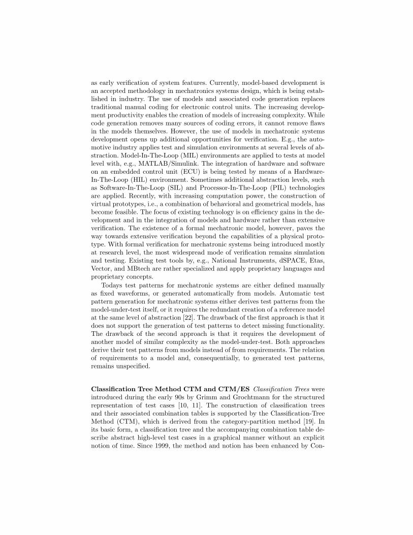
as early verification of system features. Currently, model-based development isan accepted methodology in mechatronics systems design, which is being estab-lished in industry. The use of models and associated code generation replacestraditional manual coding for electronic control units. The increasing develop-ment productivity enables the creation of models of increasing complexity. Whilecode generation removes many sources of coding errors, it cannot remove flawsin the models themselves. However, the use of models in mechatronic systemsdevelopment opens up additional opportunities for verification. E.g., the auto-motive industry applies test and simulation environments at several levels of ab-straction. Model-In-The-Loop (MIL) environments are applied to tests at modellevel with, e.g., MATLAB/Simulink. The integration of hardware and softwareon an embedded control unit (ECU) is being tested by means of a Hardware-In-The-Loop (HIL) environment. Sometimes additional abstraction levels, suchas Software-In-The-Loop (SIL) and Processor-In-The-Loop (PIL) technologiesare applied. Recently, with increasing computation power, the construction ofvirtual prototypes, i.e., a combination of behavioral and geometrical models, hasbecome feasible. The focus of existing technology is on efficiency gains in the de-velopment and in the integration of models and hardware rather than extensiveverification. The existence of a formal mechatronic model, however, paves theway towards extensive verification beyond the capabilities of a physical proto-type. With formal verification for mechatronic systems being introduced mostlyat research level, the most widespread mode of verification remains simulationand testing. Existing test tools by, e.g., National Instruments, dSPACE, Etas,Vector, and MBtech are rather specialized and apply proprietary languages andproprietary concepts.
Todays test patterns for mechatronic systems are either defined manuallyas fixed waveforms, or generated automatically from models. Automatic testpattern generation for mechatronic systems either derives test patterns from themodel-under-test itself, or it requires the redundant creation of a reference modelat the same level of abstraction [22]. The drawback of the first approach is that itdoes not support the generation of test patterns to detect missing functionality.The drawback of the second approach is that it requires the development ofanother model of similar complexity as the model-under-test. Both approachesderive their test patterns from models instead of from requirements. The relationof requirements to a model and, consequentially, to generated test patterns,remains unspecified.
Classification Tree Method CTM and CTM/ES Classification Trees wereintroduced during the early 90s by Grimm and Grochtmann for the structuredrepresentation of test cases [10, 11]. The construction of classification treesand their associated combination tables is supported by the Classification-TreeMethod (CTM), which is derived from the category-partition method [19]. Inits basic form, a classification tree and the accompanying combination table de-scribe abstract high-level test cases in a graphical manner without an explicitnotion of time. Since 1999, the method and notion has been enhanced by Con-

rad and Fey to accommodate the description of time-dependent test scenariostermed test sequences [5, 4]. These extensions are known as the Classification-Tree Method for Embedded Systems CTM/ES. The CTM/ES has recently beensuccessfully employed in different control software development projects [17].One of the main application areas is the testing of in-vehicle software developedin a model-based way [21]. Strengths of the CTM/ES approach are the descrip-tion of time-continuous test patterns [6], it may also be applied as a front-endto Time Partition Testing [18].
The CTM/ES is mainly applied in the automotive domain. Several tools ex-ist for editing classification trees (CTE/XL, Razorcat CTE) and for test dataderivation support (MTest). The syntax of classification trees is a simple graph-ical notation. Its main advantage is the combination of discrete and continuouselements by means of interpolation for stimuli generation. Randomized stimuliinstantiation is supported. However, it does not provide a gradual path towardsdirected test data definition.
Functional Verification In the domain of electronic design the concept ofmodel-based engineering across several levels of abstraction has been employedfor several decades. Formal verification, simulation and testing are employed ona regular basis. The increasing demand for verification at an early abstractionlevel, like system level, has led to the creation and introduction of methods andlanguages for functional verification. Functional verification is a methodology,which encompasses formal verification as well as simulation approaches. It buildson the declarative formulation of design properties as formal requirements, whichprovide a redundant path from natural language and semi-formal requirementsto the design to enable consistency checks. Once defined, the formal propertiescan be applied for formal verification as well as for verification by simulation.Meanwhile, libraries and methodological guidelines have become available to sup-plement the tooling and standardization efforts, such as the Verification Method-ology Manual for SystemVerilog and the Open Verification Methodology. Today,the domain of electronic design is able to apply a rather complete methodologyfor functional verification of digital designs [2].
2 Shortcomings of Mechatronic System Verification
Model-based development requires a thorough verification approach at modelinglevel before any code generation and implementation on an execution platformis performed. Generally, for verification purposes a requirements document inmodel-based development has to be accompanied by a verification document,the so-called verification plan. This document captures information, which doesnot belong into the requirements document, but is yet essential for successful im-plementation of a substantial verification task. As shown in figure 1, requirementsguide the development of a mechatronic system model, whereas the verificationplan determines verification goals, which are derived from the requirements as

Fig. 1. Verification Plan, Requirements and Mechatronic Model
well. For testing purposes, the verification plan also needs to determine the ac-tual system interfaces from the actual model-under-test. On application to themodel-under-test, execution of the verification plan connects a testbench to themodel interfaces, which then provides stimuli to the model-under-test, obtainsmeasurements from it and provides verification results to the verification engi-neer.
In comparison to the electronic design verification approach, we observe sev-eral methodical shortcomings in mechatronic system verification.
1. Support for traceability and visibility is limited.2. A methodical gap exists between requirements and testbench definition for
mechatronic systems. This is due to(a) missing methodical support for the derivation of test descriptions from
natural language requirements,(b) missing stimulus patterns which describe requirements,(c) missing requirements-based acceptance criteria,(d) missing test quality criteria for requirements coverage, which are easily
derived,3. Missing horizontal and vertical re-use of test definitions.
The limited support for traceability and visibility is due to the lack of func-tional coverage definitions, which can provide an independent means of require-ment coverage measurement for tracing tested requirements, and for visibilityof the current state of verification. The methodical gap from requirements ex-ists for several reasons: a methodical support for derivation of test descriptionsrequires a suitable target. As most requirements allow an infinite number of pos-sible stimuli, a directed stimulus definition cannot capture such a requirement,as it represents a single instance of stimulus only. However, the CTM/ES pro-vides a first step for the definition of functional stimulus patterns. The definitionof requirements based acceptance criteria for automatic acceptance evaluationis only possible usually by definition of accepting predicates. Existing predi-cate languages do not cover the definition of characteristic acceptance criteriafor continuous systems. Existing proposals for test quality criteria are usually

Fig. 2. Modules of the RailCab Shuttle
based on structural coverage criteria, which do not easily relate to requirements.Moreover, the re-use of test descriptions is only possible with high effort. Similardrawbacks have been described for mixed-signal verification in [3].
3 Example System: RailCab Suspension-Tilt Module
RailCab is a linear motor driven train system developed by the University ofPaderborn [23]. RailCab is based on shuttles, which are composed of mod-ules, which are arranged as shown in figure 2. The coach body is mounted ontwo suspension-tilt modules, which are used for active suspension and tilting.The suspension-tilt modules are coupled to the active guidance modules via airsprings. The active guidance modules can actively rotate the axles relative tothe rails to avoid striking the flange against the rail head, they also facilitate thedriving through passive shunting switches. The rotors of the linear motor formthe driving modules which provide propulsion and braking force. The active sus-pension system of the shuttle does without passive dampers in order to avoidthe propagation of high-frequency disturbance into the coach body. The forcesnecessary for the damping are computed by the control and transferred to thebody by displacing the spring bases via hydraulic cylinders [9].
The suspension-tilt module is the sub-system which links the active guid-ance modules and the coach body of the shuttle. A model of the system existsas a MATLAB/Simulink model. The model captures the functionality of onesuspension-tilt module. It also contains a model of the coach body, and a modelof the hydraulic system. The model controls the body position relative to theguidance modules. The elevation, the lateral position of the body, and its anglerelative to the longitudinal axis is controlled. The controller and plant is influ-enced by the hydraulic pressure, and by disturbing forces. The coach body is tobe controlled to provide maximum comfort for the passengers.

4 Concept for Systematic Testing of MechatronicSystems
Main goal of this new approach to systematic testing of mechatronic systemsis to narrow the methodical gap between requirements and testbenches. Exist-ing methods for functional verification and testing of mechatronic systems lackin expressiveness and do not cover all areas of functional verification. More-over, there is no accepted and standardized test definition language for controlsystems. An important precondition for a clean verification process is a plan.The concept of a verification plan is not new, however, current concepts andtools for testing mechatronic systems do only support a limited subset of theaspects of a verification plan. A verification plan has to support traceability,visibility, and repeatability. Traceability of the verification plan is provided bylinks between requirements and verification plan artifacts, namely stimulus def-initions, test quality criteria and acceptance criteria. As the purpose of testingis bug hunting, requirement violations are traced from violated acceptance cri-teria. Test “completeness” is traced from test quality criteria, which describecovered requirements. Visibility of the state of verification is provided by suchrequirements coverage. Repeatability in model-based development is maintainedthrough a deterministic simulation and test environment.
Similar to the functional requirements document as a design specification, theverification plan assumes the role of the verification specification. This documentcaptures information, which does not belong into the requirements document,but is yet essential for successful implementation of a substantial verificationtask. While the requirements are being implemented, concurrently the verifi-cation plan has to be implemented. The implementation of a verification planfrequently consumes resources in the order of the design and model implemen-tation. Increased efficiency in the process of verification plan generation andexecution therefore results in substantial savings in the overall development pro-cess.
Figure 3 gives an overview of the new concept for systematic testing of mecha-tronic systems. The verification plan is based on the requirements and a so-calledprinciple solution, which is a first step in requirements formalization [1]. For in-creased flexibility and precision of stimulus definition, constraints are applied fordeclarative stimulus definition, supported by a graphical notation similar to theCTM/ES. A new approach to acceptance criteria definition is introduced, whichapplies a graphical notation similar to CTM/ES. A new CTM/ES-like notationis applied for functional coverage definition.
Stimulus definition with constraints allows requirement based stimulus pat-tern definitions, which can be more accurately targeted for improved test qual-ity: The declarative nature of the constraint-based stimulus patterns enablesautomatic generation of a wide range of stimuli. As more implementation de-tails become available, the declarative stimulus patterns can be adapted in astraightforward manner. The new notation for acceptance criteria complementsthe stimulus pattern definition and it enables automatic acceptance criteria gen-eration together with stimuli generation for fully automatic testbench execution.

Fig. 3. Verification Plan for Systematic Testing
Moreover, the level of abstraction of the acceptance criteria definition is differentfrom that of the model-under-test. The expensive creation of a reference model atthe same level of abstraction can therefore be avoided for automatic acceptanceevaluation. Test quality criteria define verification goals. These criteria encom-pass structural coverage metrics, usually. Structural coverage metrics, however,do not enable the derivation of requirements coverage. Recently, in the domain ofelectronic design, additional test quality criteria have been introduced by meansof functional coverage. There are no approaches to functional coverage definitionfor mechatronic systems, which seamlessly fit into a verification process. A newapproach to functional coverage definition for mechatronic systems is defined,which relates to requirements and enables requirements coverage derivation.
The definition of a unified CTM/ES notation for stimulus, acceptance cri-teria, and test quality criteria immediately enables exchange and re-use of in-formation between, e.g., the stimulus and functional coverage aspects of thenotation. Functional coverage definition is a tedious process usually, which canbe alleviated by the derivation from previous stimulus pattern definitions.
The test control is described by means of the verification languages for ex-ecution of the testbench elements. Current industrial approaches to automatictestbench generation and execution are able to extract a subsystem from a sim-ulation model for, e.g., MATLAB/Simulink. The extracted subsystem interfacesare then mapped into a testbench for automatic execution. One example of sucha system is AutomationDesk from dSPACE. The automotive testbench featureslack in expressivity though in comparison to state-of-the-art “intelligent test-benches” as exist for electronic design [2, 14].
4.1 Enhanced CTM for Constraint-based Stimulus Patterns
The original CTM/ES stimuli generation process is rather monolithic and inflex-ible. It takes a classification tree, instantiates it by means of certain heuristics,

Fig. 4. CTM/ES vs. Enhanced CTM Stimuli Generation Process
interpolates between synchronization points and discretizes the stimulus for testinput as illustrated in figure 4. The enhanced CTM provides a new syntax forthe constraint based definition of synchronization points, which allows an thedefinition of constraints between synchronization point timing and value instan-tiation.
The new and enhanced stimuli generation process is based on a verificationlanguage (VL). The classification tree and constraints are mapped to the ver-ification language, which controls the further generation process of constraintsolving, interpolation, and discretization. A randomized constraint solver re-places the former instantiation step. Then, interpolation and discretization areperformed under control of the verification language. The mapping and inte-gration of the CTM syntax to a verification language allows to use verificationlanguage elements such as additional constraints with the classification tree. Thisprovides a higher control over the value instantiation, as it enables the definitionof dependencies between classifications and synchronization point times. Theenhancements over CTM/ES are summarized in table 1.
CTM/ES Enhanced CTM
Randomized instantiation + +Constraint based randomized instantiation - +Synchronization Points with fixed time + +Synchronization Points with constraint based time - +Integration with Verification Language - +
+ : supported- : unsupported
Table 1. Stimulus pattern definition with enhanced CTM
Stimulus Patterns This section illustrates the definition of stimulus patterns.First, the interface definitions are captured by a classification tree. Based on theinterface definition, a raw classification tree is partly automatically derived as de-scribed for the CTM/ES, where interfaces become combinations, signals become
4 stepz_pressvarlow
4.1 0s
4.2 +2s
4.3 +4s
4.4 +4s
4.5 +4s
4.6 +4s
4.7 +4s
Stimulus Acceptance Coverage
testbench
phi_Anr
[mrad]
y_Anr
[mm]
z_Anr
[mm]
]0,20[
20
−20
0
]−20,0[]0,90[
]125,150[
90
100
120
]90,100[
0
]100,120[
p_Versorgung
[bar]
]120,125[125
150
eval1_ifstim1_if
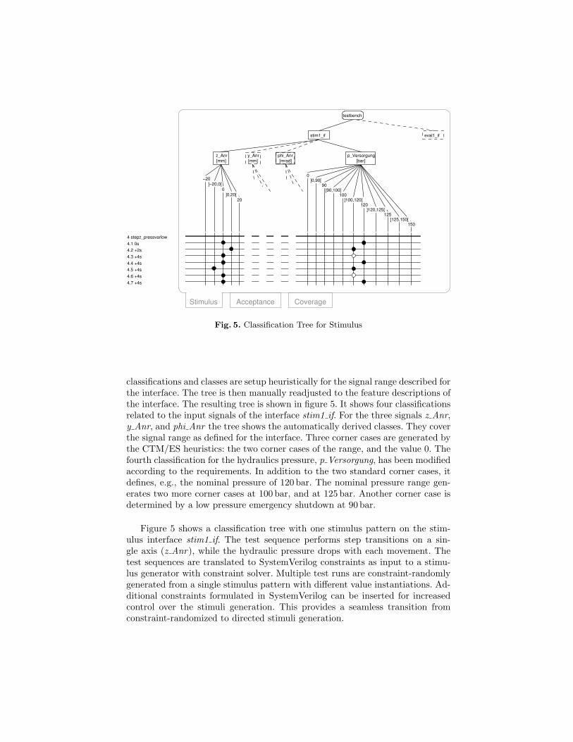
Fig. 5. Classification Tree for Stimulus
classifications and classes are setup heuristically for the signal range described forthe interface. The tree is then manually readjusted to the feature descriptions ofthe interface. The resulting tree is shown in figure 5. It shows four classificationsrelated to the input signals of the interface stim1 if. For the three signals z Anr,y Anr, and phi Anr the tree shows the automatically derived classes. They coverthe signal range as defined for the interface. Three corner cases are generated bythe CTM/ES heuristics: the two corner cases of the range, and the value 0. Thefourth classification for the hydraulics pressure, p Versorgung, has been modifiedaccording to the requirements. In addition to the two standard corner cases, itdefines, e.g., the nominal pressure of 120 bar. The nominal pressure range gen-erates two more corner cases at 100 bar, and at 125 bar. Another corner case isdetermined by a low pressure emergency shutdown at 90 bar.
Figure 5 shows a classification tree with one stimulus pattern on the stim-ulus interface stim1 if. The test sequence performs step transitions on a sin-gle axis (z Anr), while the hydraulic pressure drops with each movement. Thetest sequences are translated to SystemVerilog constraints as input to a stimu-lus generator with constraint solver. Multiple test runs are constraint-randomlygenerated from a single stimulus pattern with different value instantiations. Ad-ditional constraints formulated in SystemVerilog can be inserted for increasedcontrol over the stimuli generation. This provides a seamless transition fromconstraint-randomized to directed stimuli generation.

1 stepz_pressvarlow
1.1 0s
1.2 +2s
1.3 [1.2]+20ms
1.4 [1.2]+100ms
1.5 [1.2]+150ms
1.6 [1.2]+350ms
1.7 +4s
−20
0
eval1_if:evaluator
testbench
20
stim1_if
]0,20[
z_ul
]−20,0[
z_Anr z_ll
Stimulus Acceptance
l3
u2u1l1
u3
l2
Fig. 6. Classification Tree for Acceptance Criteria
4.2 Enhanced CTM for Acceptance Criteria
Automatic acceptance evaluation is performed by correlation to a referencemodel or by predicate evaluation [12, 13]. The definition of continuous, inter-polated behavioral boundaries is not covered by current assertion languages,therefore a reference model is required for correlation purposes. The new accep-tance criteria based on an enhanced CTM notation can provide such a referencemodel at the same level of abstraction as the stimulus pattern definition with en-hanced CTM. This replaces the effort of redundant creation of a reference modelat the same abstraction level as the model-under-test. The acceptance criteriado not attempt to capture the exact behavior of the complete model-under-test,they rather set acceptable behavioral boundaries for a certain operational rangeof the model-under-test. From the CTM representation an acceptance evaluatorin a verification language like SystemVerilog is generated. Assertions providedby the verification language supplement the acceptance criteria for reporting testresults. They provide the link to the testbench evaluation infrastructure of theunderlying execution environment.
This section illustrates the definition of acceptance criteria, which fit thestimulus defined in figure 5. The acceptance criteria define a functional relationbetween stimulus and response. They are defined by an additional classificationtree synchronized to the stimulus classification tree for automatic generation ofan evaluator (cf. figure 6). The acceptance tree is associated to the responseinterface eval1 if of the testbench. The acceptance aspect of the tree is derivedfrom the interface such that for each signal, a supremum- and an infimum signalis defined as a class. Waveforms generated for these signals enable the formula-tion of control theoretic system response criteria, such as rise times, transientovershoot, and stabilization time as described in [8, 7].

The acceptance classification tree in figure 6 starts from a root node whichrepresents the testbench. On the left hand side, the next lower node representsthe stimulus interface stim1 if, and, on the right hand side, the next lower noderepresents the evaluation interface eval1 if for the evaluator. The evaluator an-notation announces the different syntax and semantics of this part of the tree forgeneration of the evaluator. In the example tree, for the input interface stim1 ifonly the signal z Anr is shown for brevity. Below this node the combinationtable shows the test sequence stepz pressvarlow. The response signal aufbauZof the interface eval1 if is to be evaluated. The signal itself is not present inthe classification tree, visually. Instead, the limits for aufbauZ are defined be-low the combination node eval1 if:evaluator. A lower limit of aufbauZ is definedas classification z ll in the classification tree, and an upper limit is defined asclassification z ul.
In classes, functions are specified (l1, l2, ...) instead of intervals. They de-scribe the expected functional input-output relation of the model-under-test fora specific operational range. At each acceptance criteria synchronization point,a functional relation is selected, which is then evaluated in relation to the syn-chronization points of the stimulus. The acceptance criteria represent propertiesderived from the requirements and from control-theoretic quality criteria, suchas transient overshoot, and stabilization time. The definition of a functional re-lation to certain stimuli definitions enables an exact and automatic evaluationof the system behavior for automatically generated stimuli.
4.3 Enhanced CTM for Functional Coverage
The concept of functional coverage definition [20] has been transferred to classi-fication trees [15, 16] for the definition of functional coverage criteria for mecha-tronic systems. A classification tree with its value ranges and associated combi-nation table provides the basis for the definition of relevant functional coveragecriteria. The concept encompasses the coverage definition for value intervals onspecific signals, the cross-coverage of value intervals on several signals, and the(cross-) coverage of transition sequences between the value intervals. The benefitof using classification trees for this purpose is twofold: they alleviate the taskof initial formulation of functional coverage criteria and they enable hierarchicalreuse of classification tree based stimuli definitions, e.g., from previous test def-initions for sub-systems. The operational ranges of mechatronic controls can becaptured as test quality criteria, without dependency on a concrete implementa-tion of the system. In short, the CTM stimulus aspect controls the operationalranges of a system, whereas the CTM functional coverage aspect observes theactivated operational ranges of a system for independent test quality evaluation.
The new CTM notation for functional coverage definition builds on the con-cept of coverpoints employed by the major hardware verification languages inelectronic design. Coverpoints are associated to one or more signals and measurethe occurrence of several ranges of values, or sequences thereof. Cross cover-points deal with multiple signals and their value combinations. Figure 7 showsa cross coverpoint definition in classification tree notation as a sub-tree. The

11 ccp_pnormzystepmax: cross cps_pnorm, cps_zstepmax, cps_ystepmax
11.1 samelow
11.1.1
11.1.2
11.2 samem
11.2.1
11.2.2
11.3 samelow
11.3.1
11.3.2
Coverage
nstep
cps_ystepmax: coverpoint y_Anr
cps_zstepmax: coverpoint z_Anr
cross cps_pnorm, cps_zstepmax, cps_ystepmax
nstep
pstep
pstepphighplow
cps_pnorm: coverpoint p_Versorgung
pm
Fig. 7. Classification Tree for Sequence Cross Coverage
top node defines a cross coverpoint over three coverpoints associated to sig-nals p Versorgung, y Anr, z Anr. These coverpoints with their value sequencesplow,pm,phigh,pstep,nstep have been defined elsewhere in the classification treein the usual CTM notation for sequences. The combination table then describesa coverage of pairwise disturbance of the suspension-tilt platform axes y andz in the same direction. The pairwise movement is also crossed with the threenominal pressure classes. For the cross coverpoint ccp pnormzystepmax in line11, the coverpoints to be crossed are duplicated as nodes beneath an additionalclassification tree node (cross cps pnorm, cps zstepmax, cps ystepmax ) whichselects the crossed signals. On line 11.1, the bin samelow captures disturbancemovement in the same direction for the low nominal pressure range by select-ing <plow, pstep, pstep>, or <plow, nstep, nstep> on the next two lines.The pattern is repeated for the next two bins samem, and samehigh for the twopressure ranges pm, and phigh. Similar patterns define functional coverage foropposite movement of the suspension-tilt platform. By means of measurementsdefined by this functional coverage metric, it can be determined, whether move-ment of the platform has been stimulated in selected directions with 3 differentranges of hydraulic pressure. Stimulus definitions can be used as a basis for suchmetric definitions, as the syntax of the combination table remains identical.
5 Conclusion
This article introduced a new methodology and formalism for the systematic ver-ification of embedded control systems. The formalism enables the definition offormal behavioral properties for a model-based functional verification approach.The formalism applies the new Enhanced Classification Tree Method, whichwas developed based on the established Classification Tree Method for Embeded
Systems CTM/ES. A current hardware verification language was applied to def-inition and control of a verification environment. The new methodology providesimproved traceability and visibility for the verification process. It closes the gapbetween requirements and testbench definition for embedded control systems(i) by support for stimulus patterns capturing requirements, (ii) by support forrequirements-based acceptance criteria for automatic acceptance evaluation com-patible to the stimulus definition avoiding the creation of a reference model atthe same level of abstraction as the model, and (iii) by support for test qualitycriteria, which relate to specific requirements and enable requirements cover-age. Furthermore, horizontal and vertical re-use of test definitions is enabled bymeans of a unified notation. The method has been implemented in the contextof the CRC614, where it was used to verify a mechatronic function module of arailway shuttle system.
Acknowledgement This work has been partly supported by the DFG Sonder-forschungsbereich 614 and by the German Ministry for Education and Research(BMBF) through the ITEA2 project TIMMO (01IS07002).
References
[1] P. Adelt, J. Donoth, J. Gausemeier, J. Geisler, S. Henkler, S. Kahl, B. Klopper,A. Krupp, E. Munch, S. Oberthur, C. Paiz, H. Podlogar, M. Porrmann, R. Rad-kowski, C. Romaus, A. Schmidt, B. Schulz, H. Vocking, U. Witkowski, K. Witting,and O. Znamenshchykov. Selbstoptimierende Systeme des Maschinenbaus – Defi-nitionen, Anwendungen, Konzepte., volume Band 234. HNI-Verlagsschriftenreihe,Paderborn, 2008.
[2] Brian Bailey, Grant Martin, and Andrew Piziali. ESL Design and Verification: Aprescription for electronic system-level methodology. Morgan Kaufmann series insystems on silicon. Elsevier, San Francisco, CA, USA, 2007.
[3] Hamilton B. Carter and Shankar G. Hemmady. Metric Driven Design Verification.Springer, 2007.
[4] M. Conrad, H. Dorr, I. Fey, and A. Yap. Model-based Generation and StructuredRepresentation of Test Scenarios. In Workshop on Software-Embedded SystemsTesting (WSEST), Gaithersburg, USA, November 1999.
[5] Mirko Conrad. The Classification-Tree Method for Embedded Systems. InDagstuhl Seminar Proceedings 04371, 2005.
[6] Mirko Conrad and Alexander Krupp. An Extension of the Classification-TreeMethod for Embedded Systems for the Description of Events. In Second Workshopon Model Based Testing, MBT 2006, Vienna, Austria, March 2006.
[7] F. Dorrscheidt and W. Latzel. Grundlagen der Regelungstechnik. Leitfaden derElektrotechnik. B.G. Teubner, Stuttgart, second edition, 1993.
[8] Otto Follinger. Nichtlineare Regelungen II. R. Oldenbourg, Wien, seventh edition,1993.
[9] J. Geisler. Auslegung und Implementierung der verteilten Aktor- und Aufbau-regelung fur ein aktiv gefedertes Schienenfahrzeug. Master’s thesis, University ofPaderborn, Germany, 2006.

[10] K. Grimm. Systematisches Testen von Software - Eine neue Methode und eineeffektive Teststrategie (Systematic Software Testing – A new method and an ef-fective test strategy). Number 251 in GMD-Report. GMD, Oldenbourg, 1995.
[11] Matthias Grochtmann and Klaus Grimm. Classification Trees for Partition Test-ing. volume 3(2) of Software Testing, Verification and Reliability, pages 63–82,1993.
[12] J. Grossmann, M. Conrad, I. Fey, A. Krupp, K. Lamberg, and C. Wewetzer.TestML – A Test Exchange Language for Model-based Testing of Embedded Soft-ware. In Automotive Software Workshop ’06, San Diego, March 2006.
[13] J. Grossmann and W. Mueller. A Formal Behavioral Semantics for TestML. InProc. of IEEE ISoLA 06, Paphos Cyprus, pages 453–460, 2006.
[14] ITRS. International technology roadmap for semiconductors 2008 UP-DATE. http://www.itrs.net/Links/2008ITRS/Update/2008 Update.pdf, Decem-ber 2008.
[15] A. Krupp and W. Muller. Classification Trees for Random Test and FunctionalCoverage. In Design, Automation and Test in Europe (DATE 2006), Munich,Germany, March 2006.
[16] A. Krupp and W. Muller. Systematic Testbench Specification for ConstrainedRandomized Test and Functional Coverage. In 21st European Conference on Mod-elling and Simulation ECMS 2007, Prague, Czech Republic, June 2007.
[17] Klaus Lamberg, Michael Beine, Mario Eschmann, Rainer Otterbach, Mirko Con-rad, and Ines Fey. Model-based Testing of Embedded Automotive Software usingMTest. SAE 2004 Transactions, Journal of Passenger Cars - Electronic and Elec-trical Systems, 7:132–140, 2005.
[18] E. Lehmann. Time partition testing: A method for testing dynamic functionalbehaviour. In Proceedings of TEST2000, London, UK, May 2000.
[19] T. J. Ostrand and M. J. Balcer. The category-partition method for specifyingand generating fuctional tests. Commun. ACM, 31(6):676–686, 1988.
[20] Andrew Piziali. Functional Verification Coverage Measurement and Analysis.Springer, New York, USA, 2004.
[21] A. Rau. Model-Based Development of Embedded Automotive Control Systems.PhD thesis, Dept. of Computer Science, University of Tubingen, Germany, 2002.
[22] Jorg Schauffele and Thomas Zurawka. Automotive Software Engineering. Vieweg,Wiesbaden, third edition, March 2006.
[23] A. Trachtler, E. Munch, and H. Vocking. Iterative learning and self-optimizationtechniques for the innovative railcab-system. In 32nd Annual Conference of theIEEE Industrial Electronics Society — IECON’06, Paris, France, 2006.