systembeschreibung xcx 300/500/540
TRANSCRIPT

XCx 300 / 500 / 540
CNC/PLC Automation Systems Compact-, Basic- and Expansion Version System Description

2 System Description XCx 300 / 500 / 540
Contents
4
6
10
12
14
15
16
18
20
21
23
24
27
27
30
31
32
33
34
35
36
Introduction
Automation Solutions Controllers, Software and Networking
Controllers Compared From Low Cost to High End
Precise Scaleable Allrounders Performance Made-to-Measure
More than the Sum of Parts the XCx in Detail
Networking and Visualization Ethernet and OPC Server
Webserver Service Tool in the Controller
Inner Values The Structure of the XCx
I/O Interface XRIO XRIO with XCx 300 and XCx 500/540
Field Buses and Drives Standard and Optional
System Overview XCx 300 Controller, Interfaces, Periphery
System Overview XCx 500 and XCx 540 Controller, Interfaces, Periphery
Controllers
XCx 300 CNC/PLC Controller • Compact Version
XCx 500 CNC/PLC Controller • Basic Version
XCx 540 CNC/PLC Controller • Expansion Version
Expansion Modules
XP-SLM Drive Module • 4 axes • SLM protocol
XP-SRC(x) Drive Module • 2, 4, 6 or 8 Axes • Sercos
XRIO Interface Module • XRIO
XF-CANopen Field Bus Module • CANopen
XF-DPS Field Bus Module • Profibus-DP • Slave
XF-DPM Field Bus Module • Profibus-DP • Master
XF-PNS Field Bus Module • Profinet • Slave
37
38
39
40
41
41
41
42
42
43
43
43
44
45
Coupling Modules
RIO EC X2 Bus Coupler • XRIO • RIO Bus Nodes
XBCX Bus Coupler • XRIO • XCx micro Bus Nodes
X1RIO Coupling Module • XCx micro <> RIO Modules
X2RIO Coupling Module • XCx 300 / RIO <> XCx micro
Software
PLC Operating System to IEC 61131-3
CNC Operating System to DIN 66025
CNC Software Optional Extras
Multiprog Programming System to IEC 61131-3
Service Pack Utilities and Updates
Schleicher-Dialog Startup and Operation
ProCANopen CANopen Network Configuring Software
CANcard Y CANopen Field Bus Card
Accessories, Technical data
Publications Operating Manuals and System Descriptions
General Technical Data XCx Controllers and Coupling Modules

System Description XCx 300 / 500 / 540 3
XCx – Controllers of the Future... ...speed up machines and processes
1 ms PLC signal propagation time from input to output, 1 ms CNC interpolation cycle and block cycle time
...interpolate up to 16 CNC axes simultaneously in 8 NC programs
...synchronize interpolated motions with switching processes, e.g. position-dependent valve switching
...coordinate path motion with technology parameters, e.g. welding current according to path feedrate
...process freeform contours and electronic cams as well as circle and helix contours
...transform any machine kinematics into Cartesian coordinates
...control NC servo drives via positioning processors with Sercos and SLM from Control Techniques, via positioning interface modules or via CANopen
...connect the sensor / actuator level with a wide range of digital and analog I/O modules and via CANopen
...communicate as standard via Ethernet and TCP/IP in any factory network, via Profibus-DP and CAN in any system
...visualize @ Web in HTML and Java on any standard browser via integrated webserver and via OPC server for standard visualization software, and on directly connected low-cost terminals
...warn e-mail with specific alarm messages such as “Coolant low”
...diagnose and log via serial interface or direct to compact flash
...allow easy updating worldwide via compact flash

4 System Description XCx 300 / 500 / 540
Automation Solutions
for machine tools and production machines, robots and handling
Integration Complicated PLC programming of simple axis control? Doing without the convenience of a PLC in complex CNC applications? The answer is XCx. Its big feature is the integrated PLC that allows simple operation of complex CNC applications. Permanent CNC/PLC synchronization on the XCx creates unimagined new possibilities for solving complex control problems. For example, on a production line you often need coor-dinated control of feed axes – and programming that just with a PLC is complicated. On the other hand, CNC machine tools often require path-dependent dynamic control of parameters, for example in order to allow for heat expansion measured by the PLC or for exact-position valve switching. Using XCx gives you elegant solutions for these kinds of problem in a wide variety of situations: grinding • sharpening • milling • drilling • turning • cutting • machining edges and profiles • spring twisting machines •crane control • wave soldering systems • welding • painting and polishing robots • feed and removal on injection moulding and metal-bending machines • stacking and palleting • insertion and mounting work ...
Software Integration in functionality and software is a fundamental characteristic of Schleicher controllers. The real-time multi-tasking properties of the IEC 61131-3 operating system allow you to optimally adapt the controller to the process by executing time-critical functions with highest priority. The Motion Control function block library enables easy-to-parameterize axis controls even with a PLC. The optional CNC operating system to DIN 66025 gives the XCx controllers a broad additional spectrum of standard and special Schleicher functions, such as multidimensional freeform interpolation and path optimization with Nerthus software. For all controllers, configuring is carried out consistently with the programming system Multiprog according to IEC 61131-3. Hence, utilisation of software blocks and program libraries developed by the user is guaranteed across-the-controller. Multiprog is matched to the resources of the XCx to ensure easy operation. The NC-Dialog PC tool is available for starting up and operating the XCx. It communicates with the controller via Ethernet. The program automatically detects which operating system is on the controller (pure PLC or CNC/PLC) and selects the appropriate input and display masks.

System Description XCx 300 / 500 / 540 5
Networking XCx controllers are true communication professionals, open in all directions and easy to connect. Controllers can be connected via Ethernet to manage even complex and widely distributed processes. Furthermore, the classic field buses CANopen and Profibus-DP as well as the upcoming Profinet no longer serve exclusively for networking but increasingly for controlling drives. Communication via Ethernet and TCP/IP with OPC server and integrated webserver means you can run visualization and data entry on any standard browser. The parameterizing, diagnosis and test functions can be called directly on site, in the local network or on the Internet. The higher factory level can easily request production data from the XCx and integrate it elsewhere.
Concentration The XCx unites the advantages of the IPC – many interfaces, interchangeable memory media, high performance – with the efficiency and long-term stability of a conventional controller. Supported by a wide selection of digital and analog I/Os and intelligent function modules it represents a controller system that can be flexibly adapted to almost any task. XCx gains its clear speed advantage by concentrating on the essentials in combination with convenient day-to-day use.

6 System Description XCx 300 / 500 / 540
Controllers Compared
Family Ties As a supplier of automation solutions with decades of experience, Schleicher can offer a broad spectrum of controllers in all performance classes, together with the associated I/O periphery.
Performance and functionality rise with demand and com-plexity of the production process. By means of modularity and networking the XCx matches the tasks and offers automation solutions all of a piece.
XCx micro The spectrum of controllers starts with the low-cost XCx micro controller for simpler automation tasks and distributed data (pre)processing. The small PLC with 22.5 mm housing especially matches the requirements of many machine manufacturers who want to add economic and compact versions to their array of products. The controllers connect to the field bus via CANopen or Profibus-DP. In addition to the XCx micro expansion modules you can also connect modules of the RIO series. • Interfaces:
CANopen or Profibus-DP, 2x RS232
XCx 300 The low-cost XCx 300 is the obvious choice for higher demanding requirements. It is available in a range of versions as PLC and CNC/PLC. You can connect eight RIO I/O modules directly to the DIN rail via the integrated RIO interface. Via an coupling module you can also connect I/O modules from the XCx micro series. A free slot allows you to connect drives, additional I/Os or field bus interface. • Up to 4 NC axes / 2 NC
subsystems • Additional axes via Motion Control
blocks • From 2 ms CNC interpolation cycle• Interfaces:
Ethernet, RS232, RS422, XRIO, 2x interrupt, Compact Flash
• Additional interface (CANopen, Profibus-DP, Sercos, XRIO) via card
XCx 500 / XCx 540 The XCx 500 is available as PLC and CNC/PLC versions, too. The controllers offer multiple interfaces for easy integration in the widest variety of production conditions. Digital, analog and function modules from the comprehensive RIO or XCx micro system connect the I/O level via the XRIO high-speed interface. The XCx 540 expansion version has all the features of the XCx 500, as well as 4 expansion slots for additional XRIO nodes and field bus and drive interfaces. • Up to 16 NC axes / 8 NC
subsystems • Additional axes via MC blocks • From 1 ms CNC interpolation cycle• Interfaces:
CANopen, Ethernet, USB, RS232, RS422, XRIO, 2x interrupt, IrDA, Compact Flash
• Additional interface (Sercos, Profibus-DP, Profinet, XRIO) via card (XCx 540 only)

System Description XCx 300 / 500 / 540 7
Typology XCx stands for eXperienced Controller. The controllers are available in a range of versions with PLC and CNC/PLC operating system.
• XCS with PLC operating system • XCM with PLC operating system and additional Motion Control functions (MC) • XCN with CNC and integrated PLC operating system • XCN+MC with CNC and PLC operating system and additional MC functions
XCx 700 The XCx 700 is the CNC/PLC controller for complex tasks and high requirements of speed and precision. It connects the I/O level with a wide range of digital and analog input, output and combination modules from the proven Promodul-U series. Relay modules, function modules for analog value processing and temperature control, and modules for axle positioning with Sercos interface or analog setpoint interface round off the periphery range. • Up to 32 NC axes / 16 NC
subsystems • Additional axes via Motion Control
blocks • From 1 ms CNC interpolation cycle • Interfaces:
CANopen, Ethernet, 2x RS232, RS422/RS485, Compact Flash
• Additional interface (Sercos) via expansion module
XCx 1100 The XCx 1100 connects the advantages of the classic controller with those of the modern IPC with CPUs up to Intel Core 2 Duo for extreme high performance. Passive cooling and solid state disk instead of rotating mechanical devices guarantee steady operation even in rough enviroment. There is also no need for an uninterruptible power supply. The operating system VxWorks with Windows XP embedded saves process data remanently, so it always starts from a defined condition. Expansion modules are available from the Promodul-U series. • Up to 64 NC axes / 32 NC
subsystems • Additional axes via Motion Control
blocks • From 1 ms CNC interpolation cycle• Interfaces:
CANopen, 5x Ethernet, 4x USB, RS232, RS422/RS485, DVI-I
• Additional interface (Sercos III, Profinet) via PCIe expansion moduls
ProNumeric ProNumeric is an IPC-based high performance CNC/PLC automation system where even complex applications are easy to operate. It consists of a computer box and a separate operator panel. Four slots for PCI cards allow you to run multi-axis applications with 64 Sercos drives in up to 32 subsystems. Fully tested hardware / software systems guarantee steady operation. As ProSyCon the system is available as pure PLC without CNC functionalities. • Up to 64 NC axes / 32 NC
subsystems • Additional axes via Motion Control
blocks • From 1 ms CNC interpolation cycle• Interfaces:
2x USB, 2x RS232, 2x PS/2 • Slots:
4x PCI, 3x ISA, 1x AGP • CANopen and Sercos interfaces
via cards

8 System Description XCx 300 / 500 / 540
XCx 300 / 500

System Description XCx 300 / 500 / 540 9
/ 540

10 System Description XCx 300 / 500 / 540
Precise Scaleable Allrounders
XCx 500 The basic version in the XCx family offers convincing per-formance and a wide range of interfaces.
• 1 ms PLC signal propagation time
via XRIO, from 1 ms CNC interpolation cycle from 1 ms block cycle time
• Up to 16 interpolated axes in 8 NC subsystems
• 0.2 ms for 1K PLC instructions • Operating mode lockswitch • 2 fast interrupt inputs/outputs • DIN rail or screw mounting, any
orientation, no fan • Interfaces:
• Ethernet for networking • XRIO for connecting plant-floor I/Os• CANopen for field bus and drives • RS422 for operator panels • RS232 for programming • USB for additional communication • Compact Flash for operating system
and user data
XCx 540 The expansion version has all the features of the XCx 500, as well as 4 expansion slots for additional XRIO nodes and drive interfaces.

System Description XCx 300 / 500 / 540 11
With Made-to-Measure Performance
Extras The XCx 300 offers one slot for expansion cards– the XCx 540 four. This means you can adapt the controllers even more strongly to the conditions, be it additional I/O nodes, field bus networking or drive interfaces. For possible com-binations of controller and expansion card, please turn to page 20.
XCx 300 The low-cost XCx 300 is the obvious choice for less deman-ding requirements. You can connect eight I/O modules from the RIO or XCx micro series directly to the DIN rail via the integrated RIO interface. A free slot allows you to connect Sercos, an additional XRIO interface, or a Profibus-DP or CANopen field bus interface. • 1 ms PLC signal propagation time via XRIO,
from 1 ms CNC interpolation cycle from 1 ms block cycle time
• Up to 4 interpolated axes in 2 NC subsystems • 0.5 ms for 1K PLC instructions • Mode switch • 2 fast interrupt inputs/outputs • DIN rail installation, no fan • Interfaces:
• Ethernet for networking • XRIO for I/O connection direct to controller • RS422 for operator panels • RS232 for programming • Compact Flash for operating system and user data
Periphery A wide range of digital, analog and expert modules connect the I/O level. • XCx 300
Up to eight expansion modules can be connected via the integrated XRIO interface directly to the DIN rail, either from the RIO I/O series or – via a coupling module – from the XCx micro series.
• XCx 500/540 Via special bus couplers expansion modules from the RIO or XCx micro series can be connected.
With the field bus interface you can also realize other I/O nodes.

12 System Description XCx 300 / 500 / 540
More than the Sum of Parts –
Assembly is simply by mounting on a standard DIN rail. Where there is a high mechanical load the XCx 500/540 can also be screwed down directly in any orientation. All XCx operate without a fan, so free air circulation has to be ensured. The three-position operating mode switch sets the startup behaviour of the controller. On the XCx 500/540 it is a key-operated switch, on the XCx 300 a slide switch. The PROG setting means PLC stop, programming mode. In this position a new PLC program or a boot project can be transferred to the controller from the programming system. WARM is the default setting (warm start of PLC, retain variables), while COLD causes cold start of the PLC and the retain variables are reinitialized. The reset button under the front opening causes a hardware reset, equivalent to power off. This button functions only in PROG mode. The LEDs give information on the CPU and PLC status, as well as the activity of the interrupt input/outputs.
The RS422 interface (X1) is for direct connection of operator panels and displays, for example the COP handy. The terminal strip (X2) on the right contains the connection for supply voltage as well as a ready contact (ready-for-operation relay). On PLC stop (e.g. due to operational malfunction) the relay releases and can thus trigger external safety switching devices. The two combination interrupt channels are unique in this price class. Each contact can be used as either input or output. The reaction time of each channel is less than 0.2 ms. The XCx can communicate with active terminal devices such as notebooks via the USB port (X3). The connection corresponds to USB version 2.0 with a type B connector. The XRIO interface (X4) allows you to connect digital or analog I/O modules. A high-speed protocol without field bus delay controls the modules via the serial interface. This connection reduces the PLC signal propagation time from input terminal to output terminal to less than 1 millisecond. For more on the I/O interface see page 18.
XCx 540
Except for the four extensionslots (right) the XCx 540 is
identical with the XCx 500.

System Description XCx 300 / 500 / 540 13
the XCx in Detail
With CANopen (X5) the XCx 500/540 offers a standard field bus interface for controller networking, connecting drives, valve groups and special devices, and above all setting up additional I/O nodes. Up to 64 bus nodes are possible without repeaters. The RIO or XCx micro series offers digital, analog and expert modules with various numbers of channels, allowing configurations with up to 8000 I/O channels. In practice performance requirements are the only restriction. CANopen as a drive interface opens up a further field of application for axis control with no extra work. On the XCx 540 you can also connect other drive inter-faces (→ ). The XCx 300 can be equipped with an optional CANopen interface via its expansion slot. IT networking is via Ethernet (X6) and TCP/IP with 10 or 100 Mbit/s (RJ45 connection). You can connect several controllers directly (via global PLC variables) or via a PC network. OPC servers then undertake communication with standard programs for visualiza-tion and operation. For more on networking see page 14. The RS232 interface is for serial connection of programming devices, logging printers and barcode readers. The LEDs on top display the Ethernet status and the transmission rate (10/100 Mbit/s).
The operating system and user data are saved on a compact flash card. The high memory capacity of the cards means that other data such as project documen-tation, maintenance manuals and the HTML and Java scripts of the webserver is also available directly on the controller. The compact flash (CF) and be plugged and unplugged during operation and the system status is available on the PLC. Data that should be saved automatically on the CF (e.g. log book) is saved on the controller RAM and transferred automatically when a CF is available again. The LEDs on top display the status of compact flash, XRIO and CAN network and module status (XCx 500/540) or Compact Flash and Ethernet status (XCx 300). The XCx has four expansion slots: • XRIO interface for more plant-floor I/O channels • Field bus interface
• Profibus-DP (master/slave) • Profinet (slave)
• Drive interfaces • Sercos (open drive interface) • SLM (Control Techniques)
On the XCx 300 a free slot allows you to connect Sercos, an additional XRIO interface, a Profibus-DP or CANopen field bus interface. XCx 300
On the XCx 300 the I/O level is connected by an integrated interface (coupler), where the modules connect directly on the DIN rail.

14 System Description XCx 300 / 500 / 540
Networking and Visualization
XCx Interconnected Ethernet networking via TCP/IP is a central element on every XCx. In production lines, for example, it may make sense to distribute the tasks to several networked XCx controllers, which are then controlled via one or more operating units. Complex manufacturing processes are much easier to design with this modular and scaleable control concept than with centralized architecture. You can connect several controllers directly via global PLC variables, or via a PC network. OPC servers run the communication with standard visualizing and operating programs. When the XCx is operated directly on a PC via a crosslink cable you do not have to change the preset IP address. But if you want to operate larger networks you will have to use the option of assigning individual IP addresses. The IP address is saved on the compact flash.
OPC Server OPC (OLE for Process Control) is a defined set of interfaces, based on OLE/COM and DCOM technology, for open data exchange between automation and controller appli-cations, field periphery and business/office applications. OPC is based on COM (Microsoft Component Object Model), a software architecture that allows a program to use another program’s interface in order to obtain data from it (if it is also programmed as a COM component). DCOM (Distributed Component Object Model) is the net-work version of the COM system. The OPC server is part of the Multiprog programming system (see page 42) and is installed on the PC together with it. It allows process data exchange between the XCx and e-manufacturing programs such as standard visualization programs and Visual Basic applications. In the variable dialogs on Multiprog the controller data and variables where the OPC server requires read/write access are simply designated OPC.
System Description XCx 300 / 500 / 540 15
Webserver – One for All
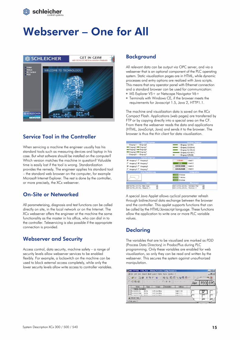
Service Tool in the Controller When servicing a machine the engineer usually has his standard tools such as measuring devices and laptop in his case. But what software should be installed on the computer? Which version matches the machine in question? Valuable time is easily lost if the tool is wrong. Standardization provides the remedy. The engineer applies his standard tool – the standard web browser on the computer, for example Microsoft Internet Explorer. The rest is done by the controller, or more precisely, the XCx webserver.
On-Site or Networked All parameterizing, diagnosis and test functions can be called directly on site, in the local network or on the Internet. The XCx webserver offers the engineer at the machine the same functionality as the master in his office, who can dial in to the controller. Teleservicing is also possible if the appropriate connection is provided.
Webserver and Security Access control, data security, machine safety – a range of security levels allow webserver services to be enabled flexibly. For example, a lockswitch on the machine can be used to block external access completely, while only the lower security levels allow write access to controller variables.
Background All relevant data can be output via OPC server, and via a webserver that is an optional component of the PLC operatingsystem. Static visualization pages are in HTML, while dynamic processes and entry options are realized with Java scripts. This means that any operator panel with Ethernet connection and a standard browser can be used for communication: • MS Explorer V5+ or Netscape Navigator V6+ • Terminals with Windows CE, if the browser meets the
requirements for Javascript 1.5, Java 2, HTTP1.1. The machine and visualization data is saved on the XCx Compact Flash. Applications (web pages) are transferred by FTP or by copying directly into a special area on the CF. From there the webserver reads the data and applications (HTML, JavaScript, Java) and sends it to the browser. The browser is thus the thin client for data visualization. A special Java Applet allows cyclical parameter refresh through bidirectional data exchange between the browser and the controller. This applet supports functions that can be called by the HTML/Javascript language. These functions allow the application to write one or more PLC variable values.
Declaring The variables that are to be visualized are marked as PDD (Process Data Directory) in ProdocPlus during PLC programming. Only these variables are enabled for web visualization, so only they can be read and written by the webserver. This secures the system against unauthorized manipulation.

16 System Description XCx 300 / 500 / 540
Inner Values –
DECODER • Parallel program memory management for
8 subsystems • Standard and advanced to DIN 66025 • Fully parameterizable programming with cycles PATH PREPARATION • Up to 16 independent interpolating axes • Tool compensation • Transformation INTERPOLATOR • Straight, circular, freeform interpolation • Electronic cams • Reverse processing of programs • Special cycles • Switching signals SHARED RAM • Functional data exchange with the integrated
permanent-synchronous PLC
PROGRAMMING LANGUAGE • IEC 61131-3 • Instruction list (IL), function block diagram (FBD),
ladder diagram (LD), structured text (ST), sequential function chart (SFC)
PROGRAM STRUCTURE • Program organization units (POUs):
Functions, function blocks, programs PLC RUNTIME SYSTEM • Multitasking:
Cyclical tasks (priority-controlled), event tasks, system tasks
PERIPHERY • Drives • Digital/analog I/O, expert modules • Field buses

System Description XCx 300 / 500 / 540 17
The Structure of the XCx
Operating System The PLC and CNC runtime and the optional webserver run on the real-time multitasking operating system VxWorks. PLC configuring is carried out with the Windows programming system Multiprog, while the CNC and PLC are started up and operated using the Schleicher-Dialog software. For more on operating and programming systems see page 41.
Shared RAM One special highlight of the XCx is direct coupling of CNC functions with PLC according to IEC 61131. This is practically unique on the market. The PLC and CNC systems simultaneously access one shared RAM to exchange data. The PLC can fulfil a master function. In the multi-tasking operating system PLC task 6 is synchronized with the inter-polation task of the CNC controller. The cycle time of task 6 is then oriented on the interpolation cycle of the CNC. Shared RAM data takes the form of variables as per IEC 61131-3, which are declared as global variables during configuring in Multiprog. They are accessible to the OPC server as standard and are displayed in the NC dialog. The close link between the CNC and the PLC system now enables you to carry out complex processes which would not be possible with separate CNC and PLC controllers. You can, for example, synchronize the PLC with position control. The PLC can also activate sensor signals in the position control cycle. This enables you to create highly dynamic sensor-driven CNC functions. • Valve control linked to path motion • Position detection on interrupt signal • Welding current according to path feedrate This means that the engineer can use a PLC user program to test the effects of end-user actions on the CNC before they are actually executed, and activate the relevant error messages or warnings. Example: thermal displacement In order to compensate for positional displacement caused by operational thermal expansion, temperature measure-ments are made at the critical points. The PLC uses this data to calculate compensation values and sends them to the CNC, which includes them in its interpolation.
Multitask In a real-time multi-tasking operating system the PLC is priority-controlled to optimize computing capacity for each task. A task is made up of program modules and is assigned precisely the amount of time required to process it. This means that valuable performance is not wasted in unnecessary waiting cycles. Furthermore, the tasks are assigned different priorities that ensures they are processed in order of importance. • Supervisor tasks (supervisor task level)
detect errors (division by zero, task overrun, etc.) and activate the corresponding operating system task.
• User and default tasks (user task level) • Cyclical tasks execute the programs assigned to them
within a defined interval under a defined priority. The task with the highest priority is called first.
• Event tasks are started by the XCx operating system when particular events occur, for example interrupt signal, CANopen task or interpolation task.
• Default task is activated when all higher-priority user tasks have been processed.
• Operating system tasks (system task level) such as communication, debugging, memory manage-ment and system control run outside the control of the user.
Task Priorities
The XCx supports 8 user tasks. The time-critical programs of the machine process are controlled in the fast high-priority tasks. Comprehensive user guidance can be processed in the mid-range tasks, and non-time-critical monitoring programs in the low priority tasks. Tasks are processed in order of priority, ensuring that the critical processes are handled first, and completely. The less critical processes are handled in the remaining time according to their priority. Example: PLC program with three tasks Task 1 • Cycle time 1 ms • Processing time 0.3 ms Task 2 • Cycle time 2 ms • Processing time 0.5 ms Task 3 • Cycle time 4 ms • Processing time 1.5 ms

18 System Description XCx 300 / 500 / 540
I/O Interface XRIO
XRIO versus Field Bus XCx connects the direct I/O level in a number of different ways: • via Schleicher-specific XRIO bus • via field buses CANopen, Profibus-DP and Profinet The proprietary high-speed interface XRIO provides external accessibility of the internal controller bus. This connection reduces the PLC signal propagation time from input terminal to output terminal to less than 1 millisecond. Electrically XRIO is similar to Interbus-S. It is a point-to-point connection with one data link for each transmission direction, according to RS422 with 500 kBit/s transmission rate. The XRIO I/O driver interfaces connected RIO modules, provides corresponding input and output maps, and refreshes them. The minimum task cycle time is largely determined by the transmission time, that on its part is determined by the number of bytes to be sent. A transmit time of 22 μs per byte can be taken as a rule of thumb. The maximum task cycle time is 80 ms. In case of exceeding the maximum time the watchdog for the RIO modules triggers, and the LED XRIO on the controller is red. The XCx operating system automatically recognizes the XRIO configuration. If the current configuration differs from the previously saved configuration automatic PLC start will not be carried out. The XRIO configuration is saved on the XCx compact flash. Bus Nodes A bus node comprises the bus coupler and up to 8 expansion modules from the RIO or XCx micro series providing up to 128 digital or 56 analog channels per node. • Digital I/O Modules
with up to 16 channels detect and switch control and position signals from the process level
• Analog I/O Modules detect 2- or 4-channel measured values and pass position signals to the process level
• Function Modules The function modules for temperature, counter and axis control allow data processing to take place directly in the bus node.
You will find more information on RIO and XCx micro series in the appropriate system descriptions and manuals (→ page 44).
XCx 300 The XCx 300 has an integrated XRIO interface. Up to eight expansion modules can be connected directly to the DIN rail, either from the RIO I/O series or – via a coupling module – from the XCx micro series. XCx 300 ↔ RIO-I/O The RIO modules connect directly to the controller, the internal bus connection is provided by integrated slide contacts. XCx 300 ↔ Coupling Module ↔ micro-I/O The micro modules connect to the controller via the X2RIO coupling module (→ page 40), the internal bus connection is provided by lateral connectors. Further Expansion The free slot on the XCx 300 allows you to connect an additional XRIO interface for more I/O nodes (→ page 32).

System Description XCx 300 / 500 / 540 19
XCx 500/540 The XCx 500 and 540 controllers are equipped with a XRIO interface by default, the XCx 540 expansion slots can be equipped with three more XRIO cards additionally. That provides four times four bus nodes with 8 modules each and a total of more than 2000 digital I/Os. Connecting the bus nodes to the XRIO interface on the controller is done using two different bus couplers: • RIO EC X2 – connects directly to RIO modules or to
micro modules via X2RIO coupling module (→ page 37) • XBCX – connects directly to micro modules or to RIO
modules via X1RIO coupling module (→ page 38) Both bus couplers can be mixed within a bus segment, as well as the I/O modules from the RIO or micro series within a bus node (using a coupling module, see right).
The bus couplers provide interfaces for incoming and outgoing data links. The max cable length is 10 meters between two connection points.
Coupling Modules The expansion modules of the RIO and micro series can be mixed within a bus node if required. Two coupling modules are available; both have no electronic components and require no power supply: • X1RIO couples from micro to RIO (→ page 39) • X2RIO couples from RIO to micro (→ page 40)

20 System Description XCx 300 / 500 / 540
Field Buses and Drives
Field Buses With CANopen the XCx offers a field bus interface for controller networking, special devices, and setting up additional I/O nodes with more than 8000 I/O channels (→ page 33). Using one of the Profibus expansion modules you can also turn the XCx 540 into a master or a slave in a Profibus-DP system (→ page 34). The Profinet interface module integrates XCx controllers in networks with higher-level Profinet controllers for distributed operation (→ page 36).
Drives Expansion cards for SLM (Control Techniques) and the open Sercos Standard are available as drive interfaces. The XCx 300 offers one slot for expansion cards to control up to 16 interpolated NC axes, while the XCx 540 has four. Drives, valve groups, etc. can also be controlled via field buses.
Overview – Standard and Optional
XCx 300 XCx 500 XCx 540
Standard
XRIO Interface integrated, 8 I/O modules RIO or XCx micro connected directly
4 bus nodes each with 8 I/O modules connected via external bus couplers
4 bus nodes each with 8 I/O modules connected via external bus couplers
CANopen • (dep. on version, see below) • •
Optional expansion cards (Number)
XRIO • – •••
CANopen • – –
Profibus-DP Master • – ••••
Profibus-DP Slave • – •••• Profinet Slave – – •••• SLM – – ••••
Sercos • – ••

System Description XCx 300 / 500 / 540 21
System Overview XCx 300
Standard interfaces on the XCx 300
XRIO Connects up to eight digital and analog I/Os and function modules directly on the DIN rail
CF Compact Flash for saving user programs and firmware
MMI Operating and visualizing via the RS422 operator panel interface
PRG Diagnosis and programming device interface RS232
Ethernet Programming, control networking and connecting the command level via TCP/IP
Optional expansion card
CANopen CANopen field bus for control networking, I/O nodes and drives
Profibus-DP XCx as master or slave in Profibus-DP
DRV (Sercos) Manufacturer-independent connectionof digital servo drives via Sercos interface with optical waveguides
XRIO Additional interfacing of plant-floor bus nodes with digital and analog I/Os and function modules

22 System Description XCx 300 / 500 / 540

System Description XCx 300 / 500 / 540 23
System Overview XCx 500 / XCx 540
Standard interfaces on the XCx 500 / XCx 540
CF Compact Flash for saving user programs and firmware
MMI Operating and visualizing via the RS422 operator panel interface
USB USB port as additional programming device interface
XRIO Interfacing of up to four plant-floor bus nodes with digital and analog I/Os and function modules
CANopen CANopen field bus for control networking, I/O nodes and drives
Ethernet Programming, control networking and connecting the command level via TCP/IP
PRG Diagnosis and programming device interface RS232
Optional expansions for the XCx 540
Profibus-DP XCx as master or slave in Profibus-DP
Profinet XCx as slave in Profinet
DRV (SLM) Connecting digital servo drives via SLM interface (Control Techniques)
DRV (Sercos) Manufacturer-independent connection of digital servo drives via Sercos interface with optical waveguides
XRIO Additional interfacing of plant-floor bus nodes with digital and analog I/Os and function modules

Controllers
24 System Description XCx 300 / 500 / 540
Controllers
CNC/PLC Controller • Compact Version XCx 300
The XCx 300 is the compact version of the XCx controller family where the CNC/PLC performance requirements are less high. Networking with Ethernet and TCP/IP ensures fast controller access for programming, diagnosis and operation. A free slot allows you to connect Sercos or SLM (Control Techniques), an additional XRIO interface, or a Profibus-DP or CANopen field bus interface. The I/O level is connected with I/O modules from the RIO or XCx micro series. With the integrated interface you can connect up to eight I/O modules on the DIN rail directly on the right-hand side of the controller. More I/O points can be set up with an optional XRIO interface. The optional CANopen interface realizes axis drives and makes the XCx suitable for application as a subcontroller in factory automation control systems. Configuring is carried out with the Windows programming system Multiprog according to IEC 61131-3. It is matched to the resources of the XCx to ensure easy operation. Webserver functionality is available as an optional extra. Options The controller is available in two pure PLC versions and four PLC/CNC versions, with and without CANopen interfacing. The CANopen module occupies the free slot. If you require a different configuration (e.g. Profibus-DP interfacing, XRIO interface or digital drive interface), please order the controller version without CANopen, and order the appropriate expansion module separately. XCS 300 PLC-CPU XCS 300 C PLC-CPU, with CANopen XCN 300 E CNC/PLC controller, max. 4 axes XCN 300 CE CNC/PLC controller, max. 4 axes, with CANopen XCN 300 CNC/PLC controller, max. 4 axes XCN 300 C CNC/PLC controller, max. 4 axes, with CANopen
Integrated interface for direct interfacing with RIO or XCx micro modules
RESET button
Mode slide switch
LED displays for controller, periphery, network and optional expansion card
Compact Flash for operating system and user data
X8 Slot for optional expansion card
X6 ETH RJ45 Ethernet interface
X1 RS422 interface for operator panels and displays
X2 Connection for supply voltage, interrupt inputs/outputs and BUSY contact
X7 PRG RS232 interface for programming units

Controllers
System Description XCx 300 / 500 / 540 25
Technical data XCS 300 XCS 300 C XCN 300 E XCN 300 CE XCN 300 XCN 300 C
Article number R4.501.0060.0 R4.501.0020.0 R4.501.0030.0 R4.501.0040.0 R4.501.0050.0 R4.501.0010.0
Controller PLC CNC/PLC
Hardware and memory
CPU Intel XScale PXA 210 (16 Bit, 200 MHz)
Memory SD-RAM: 16 MB S-RAM: 512 KB Flash (internal): 2 MB
Real-time clock Battery-buffered with calendar and leap year, resolution: 1 s
Buffering Min. 3 months with vanadium pentoxide lithium cell, 3V / 50 mAh + SuperCAP
Compact Flash (type 2, external) For operating system and user data 16 MB to 1 GB
CNC/PLC properties
Processing time 1 K PLC instructions
Bit: approx. 0.8 ms Byte / Word / DWord: approx. 0.5 ms
PLC signal propagation time 1 ms input to output via XRIO interface
Function blocks Any number of firmware functions and function blocks
Number of NC axes / subsystems – / – – / – 4 / 2 4 / 2 4 / 2 4 / 2
CNC interpolation cycle from – – 2 ms 2 ms 2 ms 2 ms
Block cycle time from – – 2 ms 2 ms 2 ms 2 ms
Operating system VxWorks, multitasking operating system (time-driven / priority-driven)
Number of user tasks 18
Task cycle times Programmable ≥ 1 ms (whole number)
Memory Data: max. 16384 KB Programs: 4096 KB
PLC flags Retentive: 256 KB Non-retentive: 2048 KB
Memory management Dynamic
Times and counters Any number programmable from 1 ms ... 290 h (number limited only by memory capacity)
Software / Field Bus
PLC operating system • • • • • •
CNC operating system – – • • • •
CANopen – • – • – •
Configuring Multiprog (programming environment to IEC 61131-3, incl. OPC server) • (option) ProCANopen (CANopen network configurator) • (option)
Interfaces
RS422 (X1) Operator panel interface, 8-pin plug-in terminal
Interrupt inputs/outputs (X2) * 2 combination channels (can be used as inputs or outputs), on 8-pin plug-in terminal
Ready contact (X2) Ready-for-operation relay, releases on PLC stop, on 8-pin plug-in terminal DC 24 V, max. 2 A, General Purpose, potential-free relays contact, NO
Ethernet (X6) Networking, RJ45, 10 Mbit/s
RS232 (X7) Programming and diagnosis interface, 9-pin subminiature plug connector
Slot for expansion card (X8) Slot for expansion card on CANopen versions occupied by CANopen field bus interface for I/Os and drives, 9-pin subminiature plug connector
XRIO Direct interfacing of max. 8 RIO I/O modules (via integrated coupler) or XCx micro modules (via coupling module X2RIO), max. 128 I/Os
* see general technical data, page 45.

Controllers
26 System Description XCx 300 / 500 / 540
Technical data XCS 300 XCS 300 C XCN 300 E XCN 300 CE XCN 300 XCN 300 C
Mode switch
Version 3-position lockswitch
Controller startup behaviour (→ also page 12)
PROG PLC stop, programming mode WARM Default, PLC warmstart, retain variables COLD PLC cold start, reinitialize retain variables
Reset button For hardware reset (= Power Off), effective only in PROG mode
Housing, electrical data
Dimensions (W x H x D) 125 x 125 x 129 mm
Weight 1.025 kg
Supply voltage DC 24 V (±20 %, max. 5 % residual ripple)
Power consumption max. 40 W max. 40 W
Current consumption max. 4.5 A (incl. all digital I/Os)
Isolation (from internal electronics) X1 (RS422): yes X2 (digital I/O): yes X6 ETH (Ethernet) yes X7 PRG (RS232): no X8 (free slot): yes
LED displays
L1, L2, L3, L4 Free (reserved for optional expansion module, → page 30)
CF green, on red, on
Compact Flash CF access access error
ETH green, flashing red, on
Ethernet network network access no network connection
RIO green, on green, flashing red, on yellow, on
RIO direct connection Operational Pre-operational Bus error Frame error
RUN/ERR green, on red, on red, flashing off
CPU status Operating voltage OK, no error CPU not running (watchdog) CPU has detected fatal error No operating voltage
PLC RUN yellow, on yellow, flashing off
PLC status PLC running PLC running, but outputs shut down (ready-for-operation relay released) PLC stop
I/O 1 I/O 2 yellow, on off
Interrupt input/output Input/output set Input/output not set
For general technical data see page 45.
Controllers
System Description XCx 300 / 500 / 540 27
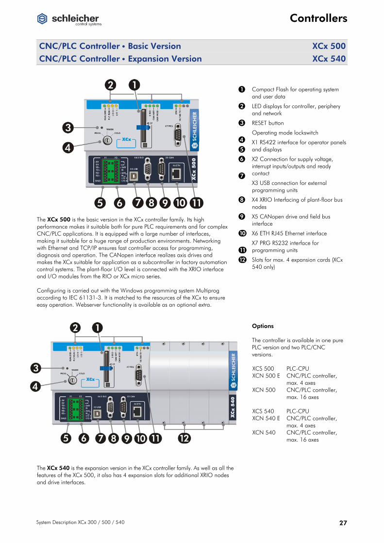
CNC/PLC Controller • Basic Version XCx 500
CNC/PLC Controller • Expansion Version XCx 540
The XCx 500 is the basic version in the XCx controller family. Its high performance makes it suitable both for pure PLC requirements and for complex CNC/PLC applications. It is equipped with a large number of interfaces, making it suitable for a huge range of production environments. Networking with Ethernet and TCP/IP ensures fast controller access for programming, diagnosis and operation. The CANopen interface realizes axis drives and makes the XCx suitable for application as a subcontroller in factory automation control systems. The plant-floor I/O level is connected with the XRIO interface and I/O modules from the RIO or XCx micro series. Configuring is carried out with the Windows programming system Multiprog according to IEC 61131-3. It is matched to the resources of the XCx to ensure easy operation. Webserver functionality is available as an optional extra.
Compact Flash for operating system and user data
LED displays for controller, periphery and network
RESET button
Operating mode lockswitch
X1 RS422 interface for operator panels and displays
X2 Connection for supply voltage, interrupt inputs/outputs and ready contact
X3 USB connection for external programming units
X4 XRIO Interfacing of plant-floor bus nodes
X5 CANopen drive and field bus interface
X6 ETH RJ45 Ethernet interface
X7 PRG RS232 interface for programming units
Slots for max. 4 expansion cards (XCx 540 only)
Options The controller is available in one pure PLC version and two PLC/CNC versions. XCS 500 PLC-CPU XCN 500 E CNC/PLC controller,
max. 4 axes XCN 500 CNC/PLC controller,
max. 16 axes XCS 540 PLC-CPU XCN 540 E CNC/PLC controller,
max. 4 axes XCN 540 CNC/PLC controller,
max. 16 axes
The XCx 540 is the expansion version in the XCx controller family. As well as all the features of the XCx 500, it also has 4 expansion slots for additional XRIO nodes and drive interfaces.

Controllers
28 System Description XCx 300 / 500 / 540
Technical data XCS 500 XCN 500 E XCN 500 XCS 540 XCN 540 E XCN 540
Article number R4.501.0070.0 R4.501.0080.0 R4.501.0090.0 R4.501.0100.0 R4.501.0110.0 R4.501.0120.0
Controller PLC CNC/PLC PLC CNC/PLC
Hardware and memory
CPU Intel StrongARM SA 1110 (32 Bit, 206 MHz)
Memory SD-RAM: 32 MB S-RAM: 1 KB Flash (internal): 2 MB
Real-time clock Battery-buffered with calendar and leap year, resolution: 1 s
Buffering Min. 3 months with vanadium pentoxide lithium cell, 3V / 50 mAh + SuperCAP
Compact Flash (type 2, external) For operating system and user data 16 MB to 1 GB
CNC/PLC properties
Processing time for 1K PLC instructions
Bit: approx. 0.4 ms Byte / Word / DWord: approx. 0.2 ms
PLC signal propagation time 1 ms input to output via XRIO interface
Function blocks Any number of firmware functions and function blocks
Number of NC axes / subsystems – / – 4 / 2 16 / 8 – / – 4 / 2 16 / 8
CNC interpolation cycle from – 1 ms 1 ms – 1 ms 1 ms
Block cycle time from – 1 ms 1 ms – 1 ms 1 ms
Operating System VxWorks, multitasking operating system (time-driven / priority-driven)
Number of user tasks 18
Task cycle times Programmable ≥ 1 ms (whole number)
Memory Data: max. 16384 KB Programs: 4096 KB
PLC flags Retentive: 256 KB Non-retentive: 2048 KB
Memory management Dynamic
Times and counters Any number programmable from 1 ms ... 290 h (number limited only by memory capacity)
Software
PLC operating system • • • • • •
CNC operating system – • • – • •
Configuring Multiprog (programming environment to IEC 61131-3, incl. OPC server) • (option) ProCANopen (CANopen network configurator) • (option)
Interfaces
RS422 (X1) Operator panel interface, plug-in terminal 8-pin
Interrupt inputs/outputs (X2) * 2 combination channels (can be used as inputs or outputs), on 8-pin plug-in terminal
Ready contact (X2) Ready-for-operation relay, releases on PLC stop, on 8-pin plug-in terminal DC 24 V, max. 2 A, General Purpose, potential-free relays contact, NO
USB (X3) Programming, diagnosis and operator panel interface, version 2.0, slave, connector type B
XRIO (X4) Proprietary field bus interface (XRIO) for connecting the RIO I/O system via special bus coupler modules (RIO EC X2), distance up to 10 m, max. 512 I/Os (XCx 540 only: more I/O modules via optional XRIO interfaces)
CAN (X5) CANopen field bus interface for I/Os and drives, subminiature 9-pin plug connector
Ethernet (X6) Networking, RJ45, 10/100 Mbit/s
RS232 (X7) Programming and diagnosis interface, 9-pin subminiature plug connector
Slots for expansion cards – 4
* see general technical data, page 45.

Controllers
System Description XCx 300 / 500 / 540 29
Technical data XCS 500 XCN 500 E XCN 500 XCS 540 XCN 540 E XCN 540
Mode switch
Version 3-position lockswitch
Controller startup behaviour (→ also page 12)
PROG PLC stop, programming mode WARM Default, PLC warmstart, retain variables COLD PLC cold start, reinitialize retain variables
Reset button For hardware reset (= Power Off), effective only in PROG mode
Housing, electrical data
Dimensions (W x H x D) 154 x 125 x 129 mm 274 x 125 x 129 mm
Weight 1.125 kg 1.85 kg
Supply voltage DC 24 V (±20 %, max. 5 % residual ripple)
Power consumption Max. 40 W Max. 40 W
Isolation (from internal electronics) X1 (RS422): yes X2 (digital I/O): yes X3 USB: no X4 XRIO (XRIO): yes X5 CAN (CANopen): yes X6 ETH (Ethernet) yes X7 PRG (RS232): no
LED displays
RUN/ERR green, on red, on red, flashing off
CPU status Operating voltage OK, no error CPU not running (watchdog) CPU has detected fatal error No operating voltage
PLC RUN yellow, on yellow, flashing off
PLC status PLC running PLC running, but outputs shut down (ready-for-operation relay released) PLC stop
I/O 1 I/O 2 yellow, on off
Interrupt input/output Input/output set Input/output not set
CF green, on red, on
Compact Flash CF access access error
XRIO green, on green, flashing red, on yellow, on
RIO direct connection Operational Pre-operational Bus error Frame error
CAN NET green, on green, flashing red, on red, flashing off
CAN network status (only on CAN versions) CAN state operational CAN state pre-operational Bus off CAN error CAN state prepared
CAN MOD green, on green, flashing red, on red, flashing
CAN module status (only on CAN versions) CAN stack initialized Invalid CAN configuration Control unit not ready or serious error Error in controller
ETH green, flashing red, on
Ethernet network network access no network connection
10/100 TX yellow, on off
Ethernet transmission rate 100 Mbit/s 10 Mbit/s
For general technical data see page 45.

Expansion Modules
30 System Description XCx 300 / 500 / 540
Expansion Modules
Drive Module • 4 Axes • SLM protocol XP-SLM
LEDs for communication drive channel 1...4 Drive interfaces X11...X14 Encoder and interrupt interfacesX15/X16
The XP-SLM drive module is a high-speed serial interface with SLM protocol (Speed Loop Motor) for data transfer to and from SLM drives and actuators made by Control Techniques. It allows positioning and position control of 4 independent NC axes. It also provides 2 encoder inputs (for connecting hand-wheels) and 2 interrupt inputs (for connecting tracers). The external power supply can be fed through a 24V power pack or via the drive (e.g. MultiAx from Control Techniques).
Serial SLM interface An SLM interface always connects 3 stations: • Motion controller (XCN with XP-SLM) • Converter (e.g. MultiAx) • Motor (e.g. Unimotor) Application example A MultiAx actuator and two Unimotors are to be connected to an XCN with the SLM drive module XP-SLM. The drives are connected to the controller via connectors X11 and X12. The diagram shows the basic wiring of the drives (without power section).
Technical data XP-SLM
Article number R4.503.0030.0
Number of controllable NC axes, max. 4
Serial SLM interfaces Number Physics Protocol
COM1+, COM1–; COM2+, COM2–; COM3+, COM3–; COM4+, COM4– 4 Two-wire RS485; 2.5 MBaud SLM (Speed Loop Motor), through ASIC CT2239-003 from Control Techniques
Hardware enable Number Switching level
HWEN1; HWEN2; HWEN3; HWEN4 4 H level = +24 V-EXT – 0.5 V • L level = 1 V
Encoder inputs Number Physics
A, /A, B, /B, NULL, /NULL 2 RS422
Interrupt inputs Number Switching level Triggering
INT+, INT– 2 H level = +11 V to +30 V • L level = –30 V to +5 V Edge triggering
Supply voltage external +24V-EXT, GND-EXT • 24 V DC ± 20% max. 5% residual ripple
Isolation By optocouplers
Accessory XP-SLM-K1-3,5
3.5 m connecting cable from the XP-SLM module to the drive (10-strand, Harting connector at one end) • Article no.: R4.506.0010.0
Connections X11...X16: har-link® 10-pin socket connector (Harting)
For controllers (number) XCN 540 (4x)
For general technical data see page 45.

Expansion Modules
System Description XCx 300 / 500 / 540 31
Drive Module • 2, 4, 6 or 8 Axes • Sercos XP-SRC(x)
LEDs for displaying Sercos startup phase (1...4) Optical fiber connections for Sercos ring: Send / Out Receive / In
The Sercos XP-SRC drive module XP-SRC(x) provides a Sercos ring on which up to 2, 4, 6 or 8 independent Sercos drives can be operated via optical fiber. A protocol implemented in the controller allows communication with a Bosch-Rexroth DriveTop interface via the serial PC interface on the XCx. Thus the drive parameters can be easily output, optimized and saved.
Application example You can connect up to 8 SERCOS drives to an XCN with the SERCOS drive module XP-SRC. The XP-SRC module is the master and the drives are the slaves. The optical fiber is connected as a ring, i.e. each output is connected to an input.
Technische Daten XP-SRC 2 XP-SRC 4 XP-SRC 6 XP-SRC 8
Article number R4.503.0200.0 R4.503.0230.0 R4.503.0260.0 R4.503.0010.0
Number of controllable NC axes, max. 2 4 6 8
interface Sercos master to IEC 1491
Cable type Plastic optical fiber, 2 / 4 / 8 / 16 MBaud
Cycle time 1 ... 30 ms
Controller Sercon 816
Displays 4 LEDs (L1 ... L4) for communication
Connections X21 Tx: Send / Out X22 Rx: Receive / In Sercos optical fiber connection IN/OUT, F-SMA screw connection to IEC 874-2
For controllers (number)
XCN 300 • (1x) • (1x) – –
XCN 540 • (2x) • (2x) • (2x) • (2x)
For general technical data see page 45.
Expansion Modules
32 System Description XCx 300 / 500 / 540
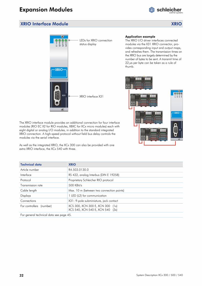
XRIO Interface Module XRIO
LEDs for XRIO connection status display XRIO interface X31
The XRIO interface module provides an additional connection for four interface modules (RIO EC X2 for RIO modules, XBXC for XCx micro modules) each with eight digital or analog I/O modules, in addition to the standard integrated XRIO connection. A high-speed protocol without field bus delay controls the modules via the serial interface. As well as the integrated XRIO, the XCx 300 can also be provided with one extra XRIO interface, the XCx 540 with three.
Application example The XRIO I/O driver interfaces connected modules via the X31 XRIO connector, pro-vides corresponding input and output maps, and refreshes them. The transmission times on the XRIO bus are largely determined by the number of bytes to be sent. A transmit time of 22 μs per byte can be taken as a rule of thumb.
Technical data XRIO
Article number R4.503.0130.0
Interface RS 422, analog Interbus (DIN E 19258)
Protocol Proprietary Schleicher RIO protocol
Transmission rate 500 KBit/s
Cable length Max. 10 m (between two connection points)
Displays 1 LED (L2) for communication
Connections X31: 9-pole subminiature, jack contact
For controllers (number) XCS 300, XCN 300 E, XCN 300 (1x) XCS 540, XCN 540 E, XCN 540 (3x)
For general technical data see page 45.
Expansion Modules
System Description XCx 300 / 500 / 540 33
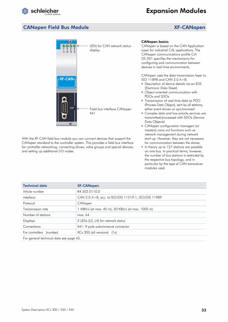
CANopen Field Bus Module XF-CANopen
LEDs for CAN network status display Field bus interface CANopen X41
With the XF-CAN field bus module you can connect devices that support the CANopen standard to the controller system. This provides a field bus interface for controller networking, connecting drives, valve groups and special devices, and setting up additional I/O nodes.
CANopen basics CANopen is based on the CAN Application Layer for industrial CAL applications. The CANopen communications profile CiA DS-301 specifies the mechanisms for configuring and communication between devices in real-time environments. CANopen uses the data transmission layer to ISO 11898 and CAN 2.0 A+B: • Description of device details via an EDS
(Electronic Data Sheet) • Object-oriented communication with
PDOs and SDOs • Transmission of real-time data as PDO
(Process Data Object), sent by all stations, either event-driven or synchronized
• Complex data and low-priority services are transmitted/processed with SDOs (Service Data Objects)
• CANopen configuration managers (or masters) carry out functions such as network management during network start-up. However, they are not necessary for communication between the slaves.
• In theory up to 127 stations are possible on one bus. In practical terms, however, the number of bus stations is restricted by the respective bus topology, and in particular by the type of CAN transceiver modules used.
Technical data XF-CANopen
Article number R4.503.0110.0
interface CAN 2.0 A+B, acc. to ISO/DIS 11519-1, ISO/DIS 11989
Protocol CANopen
Transmission rate 1 MBit/s (at max. 40 m), 50 KBit/s (at max. 1000 m)
Number of stations max. 64
Displays 2 LEDs (L3, L4) for network status
Connections X41: 9-pole subminiature connector
For controllers (number) XCx 300 (all versions) (1x)
For general technical data see page 45.
Expansion Modules
34 System Description XCx 300 / 500 / 540
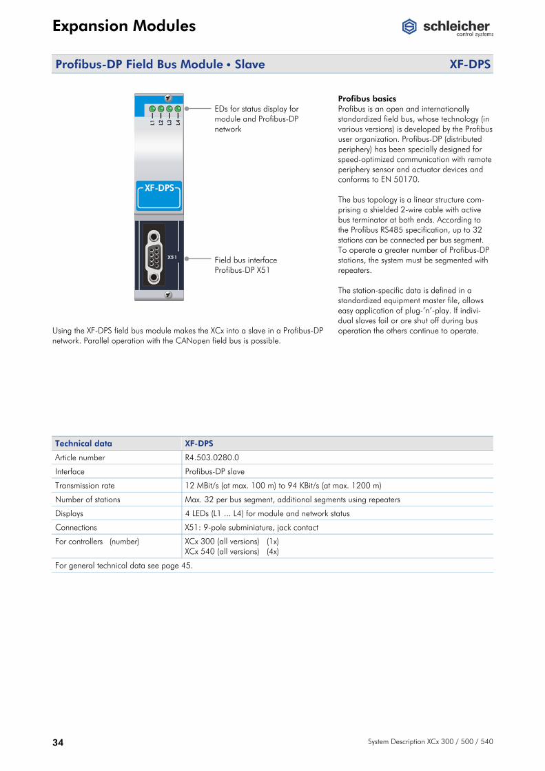
Profibus-DP Field Bus Module • Slave XF-DPS
EDs for status display for module and Profibus-DP network Field bus interface Profibus-DP X51
Using the XF-DPS field bus module makes the XCx into a slave in a Profibus-DP network. Parallel operation with the CANopen field bus is possible.
Profibus basics Profibus is an open and internationally standardized field bus, whose technology (in various versions) is developed by the Profibus user organization. Profibus-DP (distributed periphery) has been specially designed for speed-optimized communication with remote periphery sensor and actuator devices and conforms to EN 50170. The bus topology is a linear structure com-prising a shielded 2-wire cable with active bus terminator at both ends. According to the Profibus RS485 specification, up to 32 stations can be connected per bus segment. To operate a greater number of Profibus-DP stations, the system must be segmented with repeaters. The station-specific data is defined in a standardized equipment master file, allows easy application of plug-’n’-play. If indivi-dual slaves fail or are shut off during bus operation the others continue to operate.
Technical data XF-DPS
Article number R4.503.0280.0
Interface Profibus-DP slave
Transmission rate 12 MBit/s (at max. 100 m) to 94 KBit/s (at max. 1200 m)
Number of stations Max. 32 per bus segment, additional segments using repeaters
Displays 4 LEDs (L1 ... L4) for module and network status
Connections X51: 9-pole subminiature, jack contact
For controllers (number) XCx 300 (all versions) (1x) XCx 540 (all versions) (4x)
For general technical data see page 45.

Expansion Modules
System Description XCx 300 / 500 / 540 35
Profibus-DP Field Bus Module • Master XF-DPM
LEDs for status display for module and Profibus-DP network Field bus interface Profibus-DP X61
Using the XF-DPM field bus module makes the XCx into a class-1-master in a Profibus-DP network. Parallel operation with the CANopen field bus is possible.
Application example XCx 540 with XF-DPM field bus module as a bus master. The bus topology is a linear structure comprising a shielded 2-wire cable with active bus terminator at both ends. According to the Profibus RS485 specification,up to 32 stations can be connected per bus segment. To operate a greater number of Profibus-DP stations, the system must be segmented with repeaters.
Technical data XF-DPM
Article number R4.503.0310.0
Interface Profibus-DP master
Transmission rate 12 MBit/s (at max. 100 m) to 94 KBit/s (at max. 1200 m)
Number of stations Max. 32 per bus segment, additional segments using repeaters
Displays 3 LEDs (L1, L3, L4) for module and network status
Connections X61: 9-pole subminiature, jack contact
For controllers (number) XCx 300 (all versions) (1x) XCx 540 (all versions) (4x)
For general technical data see page 45.

Expansion Modules
36 System Description XCx 300 / 500 / 540
Profinet Field Bus Module • Slave XF-PNS
LEDs for status display for module and Profinet network Field bus interface Profinet X71/X72
Using the interface module XF-PNS XCx controllers can be integrated in networks with higher-level Profinet controllers for distributed operation. Real-time data exchange between master and slave as well as slave and master is done using configurable arrays.
Profinet basics The basic approach of Profinet is the appli-cation of the object model on automation technology. For this purpose, machines, plants and theit parts are divided into technological modules, each of which comprises mechanical,electrical/electronical and application soft-ware. The functionality of the technological module is encapsultad in Profinet components, which can be accessed over universally defined interfaces. The components can be combined over theit interfaces according to the modular principle and interconnected to applications. The Profinet communication model defines a vendor-indepent standard for communication on Ethernet. It uses TCP/IP and COM/DCOM,the most common standards of the PC world. It provides direct access from the office world to the automation level and vice versa (vertical integration). The integration of existing field bus systems (e.g. Profibus or CANopen) in Profinet is implemented using proxies. These assume a proxy function for all the devices connected to the field bus. This means that when rebuilding or expanding plants, the entire spectrum of devices can be implemented unchanged.
Technical data XF-PNS
Article number R4.503.0340.0
Interface Profinet slave
Transmission rate 100 MBit/s
Displays 4 LEDs (L1 … L4) for module and network status
Connections X71, X72: 2x RJ45
For controllers (number) XCx 540 (all versions) (4x)
For general technical data see page 45.

Coupling Modules
System Description XCx 300 / 500 / 540 37
Coupling Modules
XRIO Bus Coupler • RIO bus nodes RIO EC X2
LEDs for module
diagnosis
XRIO interface
X2 IN
XRIO continuation
X3 OUT
Contacts for internal bus Supply voltage In/Cont +24 VDC 0 VDC PE
The RIO EC X2 bus coupler connects the XRIO interface on the XCx 500/540 to digital, analog and function modules in the RIO I/O series. Via the X2RIO coupling module (→ page 40) you can also connect expansion modules from the XCx micro series. (The XCx 300 has an integrated bus coupler; an additional XRIO interface is available as an optional expansion module.) A bus node comprises the bus coupler and up to 8 I/O expansion modules with 128 digital or 56 analog channels. The I/O modules are connected on the DIN rail on the coupler. The internal bus is created by slide contacts. For more information on the RIO system please refer to the RIO system description and operating manuals (→ page 44).
Application example The RIO EC X2 bus coupler allows you to cascade four bus nodes, each with up to 8 I/O modules. For more application examles → page 18.
Technical data RIO EC X2
Article number R5.363.0160.0
Interface XRIO
Bus connection 2x subminiature 9-pin connector
Max. I/O range internal 64 bytes input data / 64 bytes output data
Supply voltage external DC 24 V (± 20 %, max. 5 % residual ripple)
Power consumption Bus coupler: 5 W from external 24 V supply connected modules: max. 5 W via internal 5 V supply
Number of attachable I/O modules 8
Cable length Max. 10 m (between two connecting points)
For general technical data see page 45.

Coupling Modules
38 System Description XCx 300 / 500 / 540
XRIO Bus Coupler • XCx micro bus nodes XBCX
Supply voltage
XRIO interface IN LED display XRIO continuation X3 OUT
The XBCX bus coupler connects XCx micro expansion modules to XCx controllers. A bus node comprises the bus coupler and up to eight expansion modules with 112 digital or 16 analog channels. This allows you to harness the full performance of the XCx micro for XCx controllers. For more information on the XCx micro system please refer to the system description and operating manual (→ page 44).
Application example The XBCX bus coupler allows you to cascade four bus nodes, each with up to 8 I/O modules. For more application examles → page 18.
Technical data XBCX
Article number In preparation
Interface XRIO
Transmission rate 500 kBit/s
Bus connection 4x 4-pin plug-in terminal
Max. I/O range internal 64 bytes input data / 64 bytes output data
Supply voltage external DC 24 V (± 20 %, max. 5 % residual ripple)
Power consumption Bus coupler: 5 W from external 24 V supply connected modules: max. 5 W via internal 5 V supply
Number of attachable I/O modules 8
Cable length Max. 10 m (between two connecting points)
For general technical data see page 45.

Coupling Modules
System Description XCx 300 / 500 / 540 39
Coupling Module • RIO Modules <> XCx micro X1RIO Connector
internal bus
Connector RIO (on right-hand side)
The X1RIO module interfaces the XCx micro modules with all RIO expansion modules. The module has no electronic components and requires no power supply.
Application example The X1RIO coupling module provides connection between XCx micro and RIO expansion modules (→ page 19).
Pow
er s
uppy
C
ontro
l uni
t Ex
pans
ion
mod
ules
X1RIO
RIO expansion modules
Technische Daten X1RIO
Artikelnummer R4.390.0020.0
Interface Internal controller bus
Supply voltage external Passive module, no supply voltage
Number of attachable I/O modules Overall a bus node comprises up to eight expansion modules (XCx micro or RIO)
For general technical data see page 45.
Coupling Modules
40 System Description XCx 300 / 500 / 540
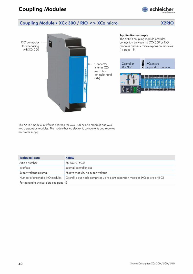
Coupling Module • XCx 300 / RIO <> XCx micro X2RIO
RIO connector for interfacing with XCx 300
Connector internal XCx micro bus (on right-hand side)
The X2RIO module interfaces between the XCx 300 or RIO modules and XCx micro expansion modules. The module has no electronic components and requires no power supply.
Application example The X2RIO coupling module provides connection between the XCx 300 or RIO modules and XCx micro expansion modules (→ page 19).
Controller XCx 300 X
2RIO
XCx micro expansion modules
Technical data X2RIO
Article number R5.363.0160.0
Interface Internal controller bus
Supply voltage external Passive module, no supply voltage
Number of attachable I/O modules Overall a bus node comprises up to eight expansion modules (XCx micro or RIO)
For general technical data see page 45.
Software
System Description XCx 300 / 500 / 540 41
Software
PLC Operating System The real-time multi-tasking properties of the IEC 61131-3 operating system allow you to optimally adapt the controller to the process. • Suitable for ultra-fast process controllers • Constant cycle times • Event tasks and cyclical tasks • Extremely short reaction time for sporadic events via
interrupt I/Os • Supports wide range of field bus and drive interfaces • Visualization via integrated OPC server
(V.1.0a Specification) • Option of synchronized CNC functions
(see below)
The PLC operating system is a component of all XCS and XCN control units. PLC and CNC are started up and operated using the Schleicher-Dialog software (→ page 43).
CNC Operating System The CNC operating system to DIN 66025 gives the XCx controllers a broad additional spectrum of standard and special functions. A complete PLC operating system to IEC 61131-3 is integrated (see above). This close meshing of CNC and PLC via the shared RAM (→ page 17) allows you to interpolate technology parameters with path motion. The CNC software on the XCx is based on Schleicher's proven CNC tools. As well as the standard CNC functions it also includes special algorithms, for example for robot control and synchronous axes. N-dimensional freeform interpolation with the Online-Curve-Interpolator (OCI) offers enormous gains in handling and machining efficiency through smooth motion and quick, steady acceleration. For up to 6 NC axes the XCN offers parallel program and tool management in several NC subsystems and flexible para-meterizability of program memory management, tool memory, circle error tolerance and axis-specific interpolation fineness.
• Suitable for extremely fast process/machine controllers • Interpolates up to 16 NC axes • NC axes are positioned precisely, interpolated and
transformed • Support for virtual line shafts and electronic cams • Processes several NC programs in parallel (option) • NC axes can be shared by several NC subsystems • Circle, helix and freeform interpolation • 3-D contour grinding cycles • Optimized robot motions • Data reduction and path optimization with Nerthus
software (option) • Online Curve Interpolator (OCI) (option) The CNC operating system is a component of all XCN control units. The number of interpolated NC axes and subsystems varies according to the controller type (→ pages 24 and 27). PLC and CNC are started up and operated using the Schleicher-Dialog software (→ page 43).
CNC Software Options Article number Designation
R4.320.0350.0 NERTHUS 6 AXES
R4.320.0460.0 CNC 03 • NC subsystems
R4.320.0620.0 CNC 06 COOR • coordinates transfomation
R4.320.0430.0 CNC 08 SSK • leadscrew compensation
R4.320.0450.0 CNC 09 • Nerthus freeform interpolation
R4.320.0440.0 CNC 10 OCI • OCI freeform interpolation
R4.320.0510.0 CNC 14 REV • reverse processing

Software
42 System Description XCx 300 / 500 / 540
Programming System to IEC 61131-3 Multiprog Configuring is carried out with the Windows programming system Multiprog according to IEC 61131-3. It is matched to the resources of the XCx to ensure easy operation. This means you have a clearly structured, easily operated tool for editing, compiling, debugging, managing and printing PLC applications in all the development phases. You can choose from five programming languages, which can be mixed as required for the task or programming style.• Text languages
• Structured text (ST) • Instruction list (IL)
• Graphic languages • Function block diagram (FBD) • Ladder diagram (LD) • Sequential function chart (SFC)
Multiprog is based on modern 32-bit Windows technology. It can be used with a mouse or via a keyboard and is easy to use thanks to tools like zoom, scroll, special toolbars, drag & drop, a shortcut manager and dockable windows. The complex structure of the IEC 61131-3 standard is presented simply and clearly. The clear structure of the Multiprog user interface makes it easy to operate. An OPC server is included in the Multiprog package (→ page 14).
The main features: • Easy creation of applications for multitasking systems • Integrated simulation makes it possible to test projects
offline (without a connected PLC) • Clear project management through a project tree based
on the Windows Explorer directory structure • Easy-to-use Edit Wizards for creating programs • Powerful documentation system with graphic editor, print
preview and cross-reference printout • Context-sensitive help for program, target system,
instruction set and language elements
Multiprog 4.0
Article number R4.320.0640.0
Contents CD 1: Programming software, OPC server CD 2: Service Pack (see below)
Operating system Windows 95/98/ME/NT4.0 (SP5 and later)/2000/XP
System requirements Pentium PC 133 MHz, 32 MB RAM, 80 MB hard disk capacity, graphics 800 x 600 pixels / 256 colours, RS232 interface optional, mouse recommended
Utilities and Updates Service Pack Article number R4.320.0590.0
Contents 1 CD: Controller software for all Schleicher controllers, AddOns, Schleicher-Dialog (→ page 43), documentations and service informations
Software
System Description XCx 300 / 500 / 540 43
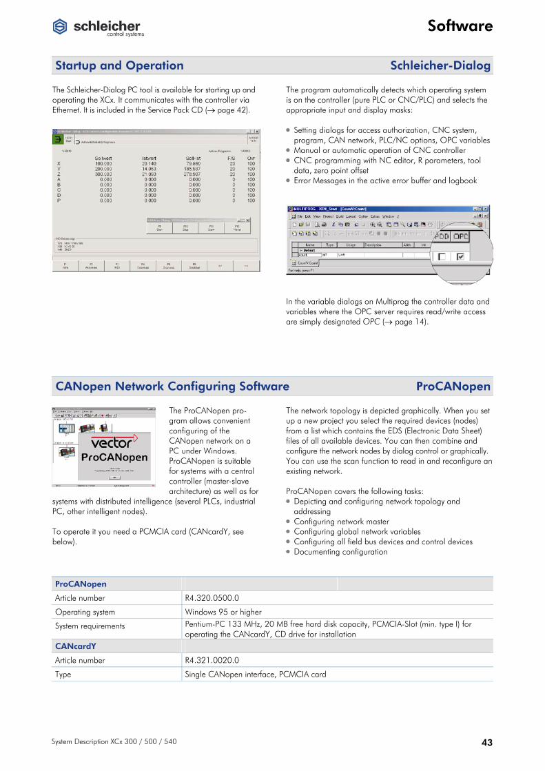
Startup and Operation Schleicher-Dialog The Schleicher-Dialog PC tool is available for starting up and operating the XCx. It communicates with the controller via Ethernet. It is included in the Service Pack CD (→ page 42).
The program automatically detects which operating system is on the controller (pure PLC or CNC/PLC) and selects the appropriate input and display masks: • Setting dialogs for access authorization, CNC system,
program, CAN network, PLC/NC options, OPC variables• Manual or automatic operation of CNC controller • CNC programming with NC editor, R parameters, tool
data, zero point offset • Error Messages in the active error buffer and logbook In the variable dialogs on Multiprog the controller data and variables where the OPC server requires read/write access are simply designated OPC (→ page 14).
CANopen Network Configuring Software ProCANopen
The ProCANopen pro-gram allows convenient configuring of the CANopen network on a PC under Windows. ProCANopen is suitable for systems with a central controller (master-slave architecture) as well as for
systems with distributed intelligence (several PLCs, industrial PC, other intelligent nodes). To operate it you need a PCMCIA card (CANcardY, see below).
The network topology is depicted graphically. When you set up a new project you select the required devices (nodes) from a list which contains the EDS (Electronic Data Sheet) files of all available devices. You can then combine and configure the network nodes by dialog control or graphically. You can use the scan function to read in and reconfigure an existing network. ProCANopen covers the following tasks: • Depicting and configuring network topology and
addressing • Configuring network master • Configuring global network variables • Configuring all field bus devices and control devices • Documenting configuration
ProCANopen
Article number R4.320.0500.0
Operating system Windows 95 or higher
System requirements Pentium-PC 133 MHz, 20 MB free hard disk capacity, PCMCIA-Slot (min. type I) for operating the CANcardY, CD drive for installation
CANcardY
Article number R4.321.0020.0
Type Single CANopen interface, PCMCIA card
Accessories
44 System Description XCx 300 / 500 / 540
Accessories
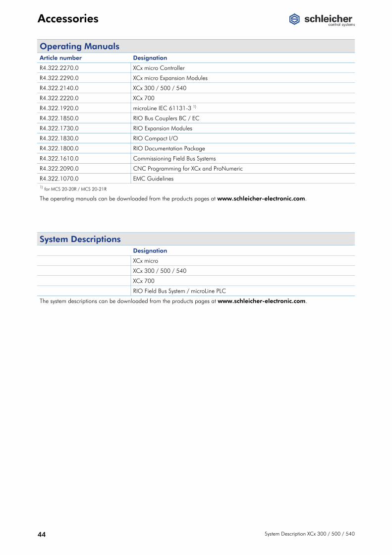
Operating Manuals Article number Designation
R4.322.2270.0 XCx micro Controller
R4.322.2290.0 XCx micro Expansion Modules
R4.322.2140.0 XCx 300 / 500 / 540
R4.322.2220.0 XCx 700
R4.322.1920.0 microLine IEC 61131-3 1)
R4.322.1850.0 RIO Bus Couplers BC / EC
R4.322.1730.0 RIO Expansion Modules
R4.322.1830.0 RIO Compact I/O
R4.322.1800.0 RIO Documentation Package
R4.322.1610.0 Commissioning Field Bus Systems
R4.322.2090.0 CNC Programming for XCx and ProNumeric
R4.322.1070.0 EMC Guidelines 1) for MCS 20-20R / MCS 20-21R
The operating manuals can be downloaded from the products pages at www.schleicher-electronic.com.
System Descriptions Designation
XCx micro
XCx 300 / 500 / 540
XCx 700
RIO Field Bus System / microLine PLC
The system descriptions can be downloaded from the products pages at www.schleicher-electronic.com.
General Technical Data
System Description XCx 300 / 500 / 540 45
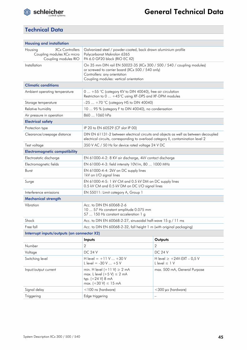
General Technical Data
Technical Data
Housing and installation
Housing XCx Controllers Coupling modules XCx micro Coupling modules RIO
Galvanized steel / powder-coated, back drawn aluminium profile Polycarbonat Makrolon 6265 PA 6.0 GF20 black (RIO EC X2)
Installation On 35 mm DIN rail EN 50022-35 (XCx 300 / 500 / 540 / coupling modules) or screwed to carrier board (XCx 500 / 540 only) Controllers: any orientation Coupling modules: vertical orientation
Climatic conditions
Ambient operating temperature 0 ... +55 °C (category KV to DIN 40040), free air circulation Restriction to 0 ... +45°C using XF-DPS and XF-DPM modules
Storage temperature –25 ... +70 °C (category HS to DIN 40040)
Relative humidity 10 ... 95 % (category F to DIN 40040), no condensation
Air pressure in operation 860 ... 1060 hPa
Electrical safety
Protection type IP 20 to EN 60529 (CF slot IP 00)
Clearance/creepage distance DIN EN 61131-2 between electrical circuits and objects as well as between decoupled electrical circuits, corresponding to overload category II, contamination level 2
Test voltage 350 V AC / 50 Hz for device rated voltage 24 V DC
Electromagnetic compatibility
Electrostatic discharge EN 61000-4-2: 8 KV air discharge, 4kV contact discharge
Electromagnetic fields EN 61000-4-3: field intensity 10V/m, 80 ... 1000 MHz
Burst EN 61000-4-4: 2kV on DC supply lines 1kV on I/O signal lines
Surge EN 61000-4-5: 1 kV CM and 0.5 kV DM on DC supply lines 0.5 kV CM and 0.5 kV DM on DC I/O signal lines
Interference emissions EN 55011: Limit category A, Group 1
Mechanical strength
Vibration Acc. to DIN EN 60068-2-6 10 ... 57 Hz constant amplitude 0.075 mm 57 ... 150 Hz constant acceleration 1 g
Shock Acc. to DIN EN 60068-2-27, sinusoidal half-wave 15 g / 11 ms
Free fall Acc. to DIN EN 60068-2-32, fall height 1 m (with original packaging)
Interrupt inputs/outputs (on connector X2)
Inputs Outputs
Number 2 2
Voltage DC 24 V DC 24 V
Switching level H level = +11 V ... +30 V L level = -30 V ... +5 V
H level ≥ +24V-EXT – 0,5 V L level ≤ 1 V
Input/output current min. H level (+11 V) ≥ 2 mA max. L level (+5 V) ≤ 2 mA typ. (+24 V) 8 mA max. (+30 V) ≤ 15 mA
max. 500 mA, General Purpose
Signal delay <100 ns (hardware) <300 μs (hardware)
Triggering Edge triggering –

General Technical Data
46 System Description XCx 300 / 500 / 540
Controller Dimensions

General Technical Data
System Description XCx 300 / 500 / 540 47
Coupling Modules Dimensions Bus coupler XBCX Coupling modules X1RIO / X2RIO
Bus coupler RIO EC X2

48 System Description XCx 300 / 500 / 540
Notes

Always There for You Schleicher stands for more than just convincing products. We also tailor them to your needs in perfect engineering solutions. Desire and Reality Do you have special requirements not covered by the range of modules presented here? Do you need special interfaces for digital or analog field peripherals, different voltage levels, input signals or output currents? Are you looking for suitable I/O interfaces for your field buses or networks? As an innovative medium-sized company, we are in a position to respond to your requests and manufacture customized devices, even in small numbers. Service and Solutions If you so wish, our specialists will of course also complete configuring and startup and service the installed system.
We help you on-the-spot with integrating our components in your existing system and developing solutions for specific tasks. With our know-how we can assist you to make the most cost-effective and efficient use of your plant, machines and systems. Theory and Practice Decades of practical expertise and experience and coopera-tion with our customers flow into our training programmes, where you can learn how to exploit the features of our products for your application. Question and Answer If you would like to know more, please call our competent hotline: tel. +49 30 33005-304. You can also find opera-ting manuals, service information, example applications and other documentation round the clock on the Schleicher website.
www.schleicher-electronic.com

Schleicher Electronic GmbH & Co. KG Pichelswerderstrasse 3-5 13597 Berlin, Germany Tel. +49 30 33005-0 Fax +49 30 33005-378 www.schleicher-electronic.com [email protected] Su
bjec
t to
mod
ifica
tions
• 0
808