systems modeling language (sysml) · systems modeling language (sysml) - systems modeling language...
TRANSCRIPT
Systems Modeling Language(SysML)
How to model Systems Engineering? Sparx Systems Enterprise Architect provides a platformfor system engineers, with the Systems Modeling Language (SysML) and model-based
development, aiding research, design, testing and management of complex systems.
Enterprise Architect
User Guide Series
Author: Sparx Systems
Date: 16/01/2019
Version: 1.0
CREATED WITH

Table of Contents
Systems Modeling Language (SysML) 3Modeling Systems in Enterprise Architect 6A SysML Requirements Model 11Block Definition Diagrams 12
Block Element Compartments 15Create a Constraint Block from Equations 18Creating Ports and Parts 25Generate Parts From Block Associations 28Nested Ports in SysML 31
A SysML Operational Domain Model 32Parametric Diagrams 34Parametric Diagram Modeling Assistant 37
Bind Parameters of a ConstraintProperty 38Compose System Design 42Create Reusable Subsystems 44Show Direction on SysML Ports 46SysML Toolboxes 47
SysML Activity Toolbox 48SysML Block Definition Toolbox 53SysML Interaction Toolbox 57SysML Internal Block Toolbox 59SysML Model Elements Toolbox 62SysML Parametrics Toolbox 66SysML Requirements Toolbox 69SysML StateMachine Toolbox 72SysML Use Case Toolbox 75
Migrate SysML Model to Later SysML Version 77Simple Parametric Simulation (Legacy) 79
Systems Modeling Language (SysML) - Systems Modeling Language (SysML) 16 January, 2019
Systems Modeling Language (SysML)
Enterprise Architect's implementation of SysML 1.5 delivers a powerful and rigorous modeling solution for SystemsEngineering professionals. This integrated modeling environment helps you to:
Specify system requirements with powerful requirements modeling support·
Design deeply-nested structures of systems and subsystems using Blocks and Block diagrams·
Analyze system-to-system behavior using Interaction diagrams, Activity diagrams and State Charts·
Define system dynamics and enforce correctness with Parametric and Constraint Blocks.·
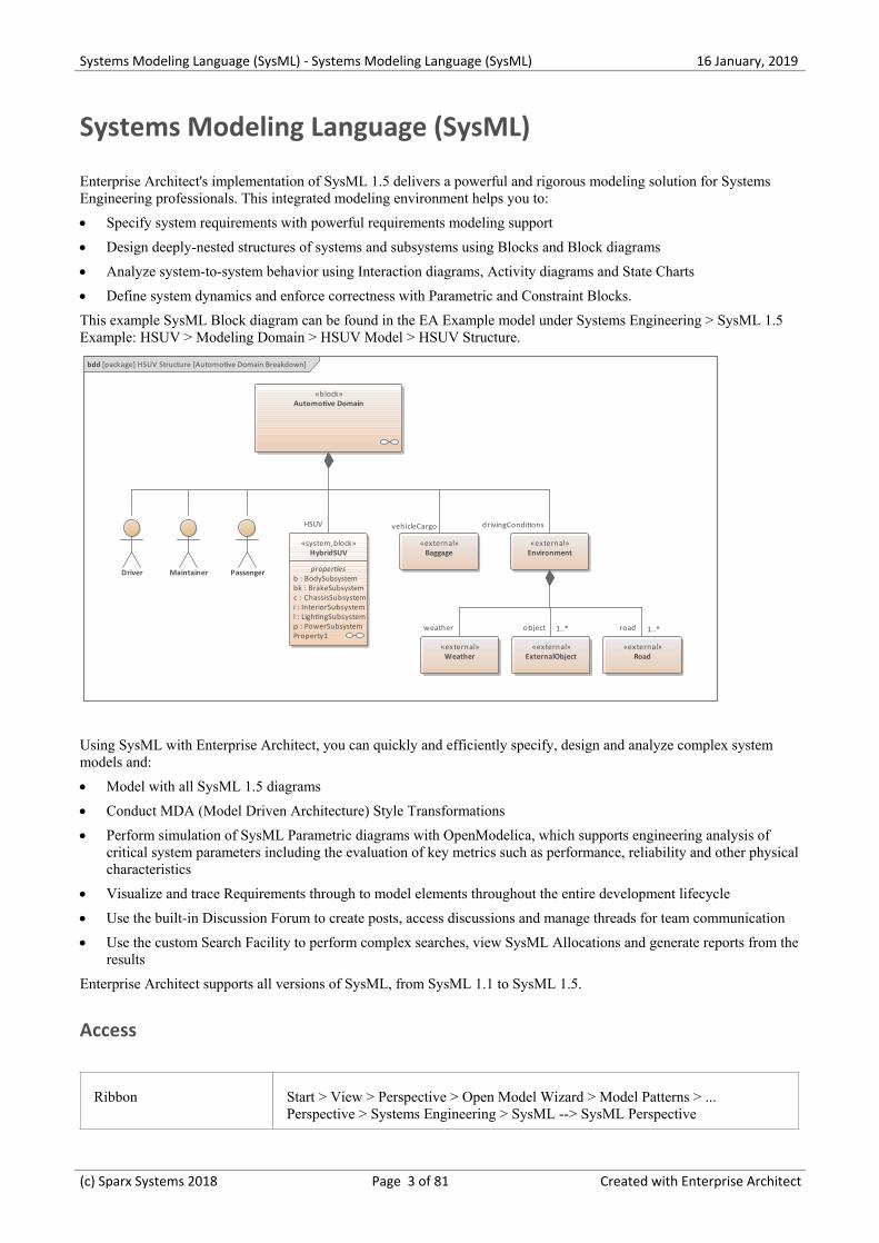
This example SysML Block diagram can be found in the EA Example model under Systems Engineering > SysML 1.5Example: HSUV > Modeling Domain > HSUV Model > HSUV Structure.
bdd [package] HSUV Structure [Automotive Domain Breakdown]
«block»Automotive Domain
Driver Maintainer Passenger
«system,block»HybridSUV
properties b : BodySubsystem bk : BrakeSubsystem c : ChassisSubsystem i : InteriorSubsystem l : LightingSubsystem p : PowerSubsystem Property1
«external»Environment
«external»ExternalObject
«external»Road
«external»Weather
«external»Baggage
weather road 1..*
HSUV
object 1..*
drivingConditionsvehicleCargo
Using SysML with Enterprise Architect, you can quickly and efficiently specify, design and analyze complex systemmodels and:
Model with all SysML 1.5 diagrams·
Conduct MDA (Model Driven Architecture) Style Transformations·
Perform simulation of SysML Parametric diagrams with OpenModelica, which supports engineering analysis of·critical system parameters including the evaluation of key metrics such as performance, reliability and other physicalcharacteristics
Visualize and trace Requirements through to model elements throughout the entire development lifecycle·
Use the built-in Discussion Forum to create posts, access discussions and manage threads for team communication·
Use the custom Search Facility to perform complex searches, view SysML Allocations and generate reports from the·results
Enterprise Architect supports all versions of SysML, from SysML 1.1 to SysML 1.5.
Access
Ribbon Start > View > Perspective > Open Model Wizard > Model Patterns > ...Perspective > Systems Engineering > SysML --> SysML Perspective
(c) Sparx Systems 2018 Page 3 of 81 Created with Enterprise Architect
Systems Modeling Language (SysML) - Systems Modeling Language (SysML) 16 January, 2019
Context Menu Right-click on a Package > Add a Model using Wizard > Model Patterns > ...Perspective > Systems Engineering > SysML --> SysML Perspective
Keyboard Ctrl+Shift+M > Model Patterns > ... Perspective > Systems Engineering > SysML--> SysML Perspective
OtherClick on the button in the top right corner of the screen, andselect the 'Systems Engineering | SysML' Perspective
SysML Integration
Facilities Detail
SysML In EnterpriseArchitect
Enterprise Architect's support for SysML provides:
A range of Perspectives and Patterns to generate SysML models, in the Model·Wizard
Patterns for each of the nine SysML diagram types, accessed through the 'New·Diagram' dialog
A collection of SysML pages in the Diagram Toolbox that contain the SysML·elements and relationships for each of the diagram types
SysML element and relationship entries in the 'Toolbox Shortcut Menu' and·Quick Linker
SysML Toolboxes Enterprise Architect's support for SysML provides Diagram Toolbox pages for thenine types of SysML diagram, which you can access through the 'Find ToolboxItem' dialog. If you enable SysML as the active technology, you can also open theSysML Toolbox pages by default. See the SysML Toolboxes Help topic.
Working with SysMLVersions
Enterprise Architect supports these SysML versions:
1.1·
1.2·
1.3·
1.4·
1.5·
However, SysML 1.5 is virtually identical to SysML 1.4 so the versions aresupported and processed as the same thing.
You can maintain your models under any of these versions, as necessary, but it isrecommended that you only work with one version at a time and disable the others,using the 'MDG Technologies' dialog (select the 'Specialize > Technologies >Manage' ribbon option). You might enable two consecutive versions if you areupgrading your models from the earlier one to the later one.
Upgrade SysML Models You can migrate a SysML model (or part of a model) to a later SysML version,using the Automation Interface. See the Migrate SysML Model to Later SysMLVersion Help topic.
(c) Sparx Systems 2018 Page 4 of 81 Created with Enterprise Architect

Systems Modeling Language (SysML) - Systems Modeling Language (SysML) 16 January, 2019
Notes
Support for SysML is built in to the Corporate, Unified and Ultimate editions of Enterprise Architect·
You can purchase an MDG Technology for SysML under separate licence to use with the Professional edition of·Enterprise Architect
Support for SysML is provided on Enterprise Architect version 12.1 or higher·
As SysML 1.5 is virtually identical to SysML 1.4, you do not need to upgrade your SysML 1.4 models; references to·the latest version of SysML have, however, been updated to '1.5'
(c) Sparx Systems 2018 Page 5 of 81 Created with Enterprise Architect
Systems Modeling Language (SysML) - Systems Modeling Language (SysML) 16 January, 2019
Modeling Systems in Enterprise Architect
Using SysML in Enterprise Architect, the process of developing a model to design or investigate a system is quick andeasy, but at the same time versatile and flexible with a full implementation of the SysML specification. An outline of thestages of the process, and the steps for the initial stage, are provided here.
Model Systems in Enterprise Architect
Work through these steps to create a model to help engineer your system.
Stage
Create a Systems Engineering Model framework
Follow the step by step guide in the table Create a Systems Engineering model from a template at the end of thistopic.
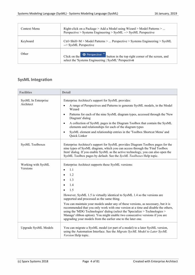
Create a Requirements model to define the systems requirements and expectations.
req [package] One Level Requirement Hierarchy [One Level Requirement Hierarchy]
«requirement»Requirement A
id = "identifierOne"text = "[Text details of Requirement A]"
«requirement»Requirement A.1
id = "identifierTwo"text = "[Text details of Requirement A.1]"
«requirement»Requirement A.2
id = "identifierThree"text = "[Text details of Requirement A.2]"
«requirement»Requirement A.3
id = "identifierFour"text = "[Text details of Requirement A.3]"
The SysML Requirements Model provides the system requirements, the expected abstract behavior, and theoperating constraints that the designed system must conform to.
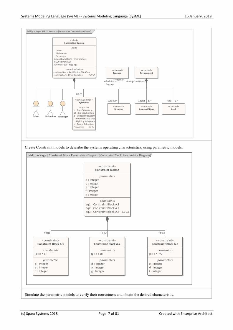
Create an Operational Domain model, which describes the environment that the system operates within, and theentities it interacts with.
(c) Sparx Systems 2018 Page 6 of 81 Created with Enterprise Architect
Systems Modeling Language (SysML) - Systems Modeling Language (SysML) 16 January, 2019
bdd [package] HSUV Structure [Automotive Domain Breakdown]
«block»Automotive Domain
parts : Driver : Maintainer : Passenger drivingConditions : Environment HSUV : HybridSUV vehicleCargo : Baggage
owned behaviors«interaction» StartVehicleBlackBox«interaction» DriveBlackBox
Driver Maintainer Passenger
«LightCondition»HybridSUV
properties b : BodySubsystem bk : BrakeSubsystem c : ChassisSubsystem i : InteriorSubsystem l : LightingSubsystem p : PowerSubsystem Property1
«external»Environment
«external»
«external»Baggage
Baggage
«external»ExternalObject
«external»Road
«external»Weather
object 1..*
vehicleCargo
road 1..*
drivingConditions
HSUV
weather
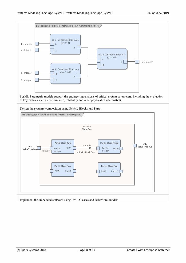
Create Constraint models to describe the systems operating characteristics, using parametric models.
bdd [package] Constraint Block Parametrics Diagram [Constraint Block Parametrics Diagram]
«constraint»Constraint Block A.2
constraints{g = a + d}
parameters d : Integer a : Integer g : Integer
«constraint»Constraint Block A.1
constraints{a = b * c}
parameters b : Integer a : Integer c : Integer
«constraint»Constraint Block A
parameters b : Integer c : Integer e : Integer f : Integer g : Integer
constraints eq1 : Constraint Block A.1 eq2 : Constraint Block A.2 eq3 : Constraint Block A.3
«constraint»Constraint Block A.3
constraints{d = e * f/2}
parameters e : Integer d : Integer f : Integer
+eq2+eq1 +eq3
Simulate the parametric models to verify their correctness and obtain the desired characteristic.
(c) Sparx Systems 2018 Page 7 of 81 Created with Enterprise Architect
Systems Modeling Language (SysML) - Systems Modeling Language (SysML) 16 January, 2019
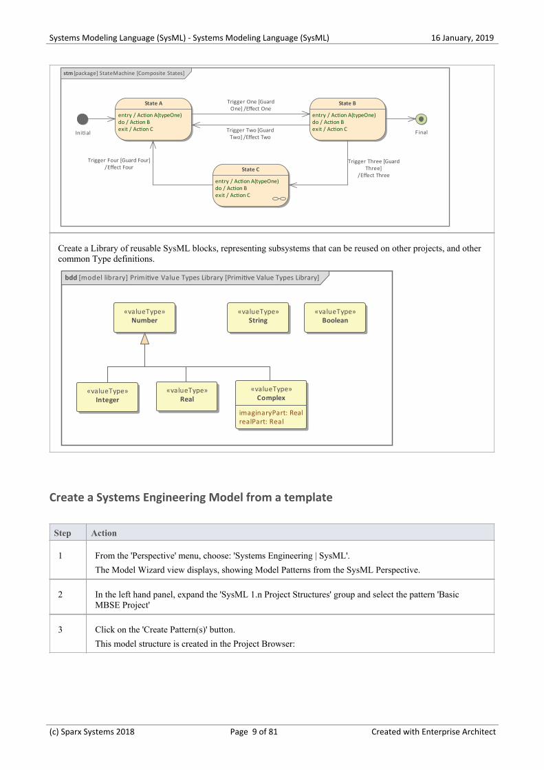
par [constraint block] Constraint Block A [Constraint Block A]
eq1 : Constraint Block A.1{a = b * c}
eq3 : Constraint Block A.3{d = e * f/2}
eq2 : Constraint Block A.2{g = a + d}
ba
c
b : Integer
de
f
d
a
c : Integer
e : Integer
f : Integer
g : Integerg
SysML Parametric models support the engineering analysis of critical system parameters, including the evaluationof key metrics such as performance, reliability and other physical characteristics
Design the system's composition using SysML Blocks and Parts
ibd [package] Block with Four Parts [Internal Block Diagram]
vto:ValueTypeOne
vtt:ValueTypeTwo
«block»Block One
vto:ValueTypeOne
vtt:ValueTypeTwo
Part1: Block Two
Port4:Integer
Port4
Part2: Block Three
Port5:Integer
Port6
Part3: Block Four
Port7 Port8
Part4: Block Five
Port9 Port10
«block» Block One
«equal»
«equal»
Implement the embedded software using UML Classes and Behavioral models
(c) Sparx Systems 2018 Page 8 of 81 Created with Enterprise Architect
Systems Modeling Language (SysML) - Systems Modeling Language (SysML) 16 January, 2019
stm [package] StateMachine [Composite States]
Initi al
State A
entry / Action A(typeOne)do / Action Bexit / Action C
State B
entry / Action A(typeOne)do / Action Bexit / Action C
State C
entry / Action A(typeOne)do / Action Bexit / Action C
Final
Trigger Three [GuardThree]
/Effect Three
Trigger One [GuardOne] /Effect One
Trigger Two [GuardTwo] /Effect Two
Trigger Four [Guard Four]/Effect Four
Create a Library of reusable SysML blocks, representing subsystems that can be reused on other projects, and othercommon Type definitions.
bdd [model library] Primitive Value Types Library [Primitive Value Types Library]
«valueType»Number
«valueType»Integer
«valueType»Real
«valueType»Complex
imaginaryPart: RealrealPart: Real
«valueType»String
«valueType»Boolean
Create a Systems Engineering Model from a template
Step Action
1 From the 'Perspective' menu, choose: 'Systems Engineering | SysML'.
The Model Wizard view displays, showing Model Patterns from the SysML Perspective.
2 In the left hand panel, expand the 'SysML 1.n Project Structures' group and select the pattern 'BasicMBSE Project'
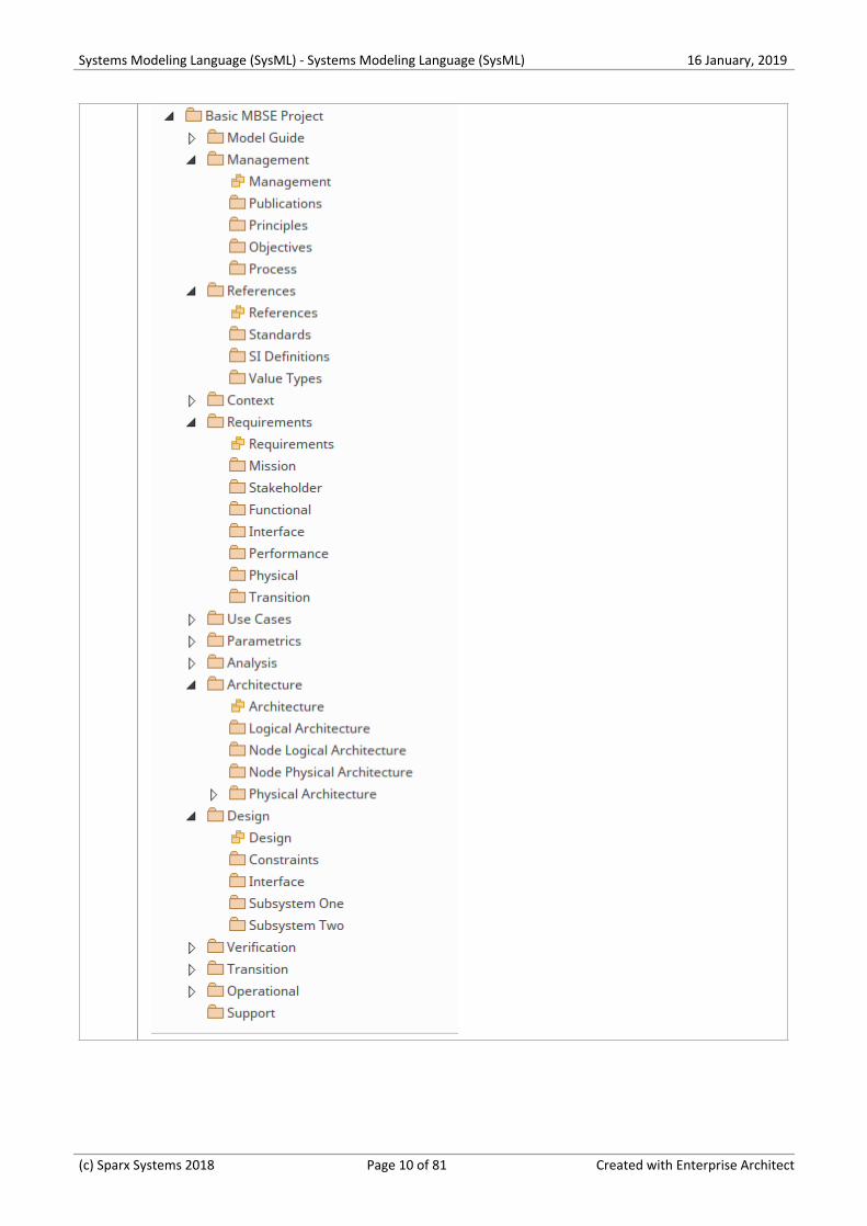
3 Click on the 'Create Pattern(s)' button.
This model structure is created in the Project Browser:
(c) Sparx Systems 2018 Page 9 of 81 Created with Enterprise Architect
Systems Modeling Language (SysML) - Systems Modeling Language (SysML) 16 January, 2019
(c) Sparx Systems 2018 Page 10 of 81 Created with Enterprise Architect

Systems Modeling Language (SysML) - Systems Modeling Language (SysML) 16 January, 2019
A SysML Requirements Model
Requirements engineering is a fundamental aspect of a systems engineering model. The discipline focuses on eliciting,analyzing and managing customer requirements early in the process. Once the requirements are understood, trade studiescan be conducted to formally assess design options, typically using weighted choices. The requirements are managed asfirst class citizens and are formally allocated to development items and verification methods.
Enterprise Architect has extensive functionality to assist the modeler with every aspect of the requirements engineeringdiscipline, including elicitation, modeling, management and testing. High quality engineering documentation can begenerated out-of-the-box using a wide range of built-in templates, carefully crafted to extract the information in themodels and present it in visually compelling and high quality documentation in a wide range of formats, including docx,pdf and html. The documentation engine is highly configurable, and documentation to match any engineering ororganizational standard can be generated by creating templates and setting generation options.
The SysML Requirements Model provides the system requirements, the expected abstract behavior and the operatingconstraints that the designed system must conform to. This diagram shows an example requirements model for a PortableAudio Player.
req [Package] Specifications [Specifications]
«requirement»Easy to Use
«requirement»Performance
«requirement»Durability
«requirement»Media Access
«requirement»Fidelity
«requirement»Noise Reduction
«requirement»Graphical User interface
«requirement»Keys Layout
«requirement»Scroller
«requirement»Battery longevity
«requirement»Weather resistance
«requirement»Shock Resistance
«requirement»Storage Capacity
«requirement»External ports
This example displays several top level requirements such as 'Ease of Use' and then breaks those requirements down intomore refined requirements such as the 'Graphical User Interface'.
(c) Sparx Systems 2018 Page 11 of 81 Created with Enterprise Architect

Systems Modeling Language (SysML) - Systems Modeling Language (SysML) 16 January, 2019
Block Definition Diagrams
A Block defines a collection of features used to describe a system, subsystem, component or other engineering object ofinterest. These features can include both structural and behavioral features, such as properties, operations and receptions,that represent the state of the system and the behavior that the system might exhibit.
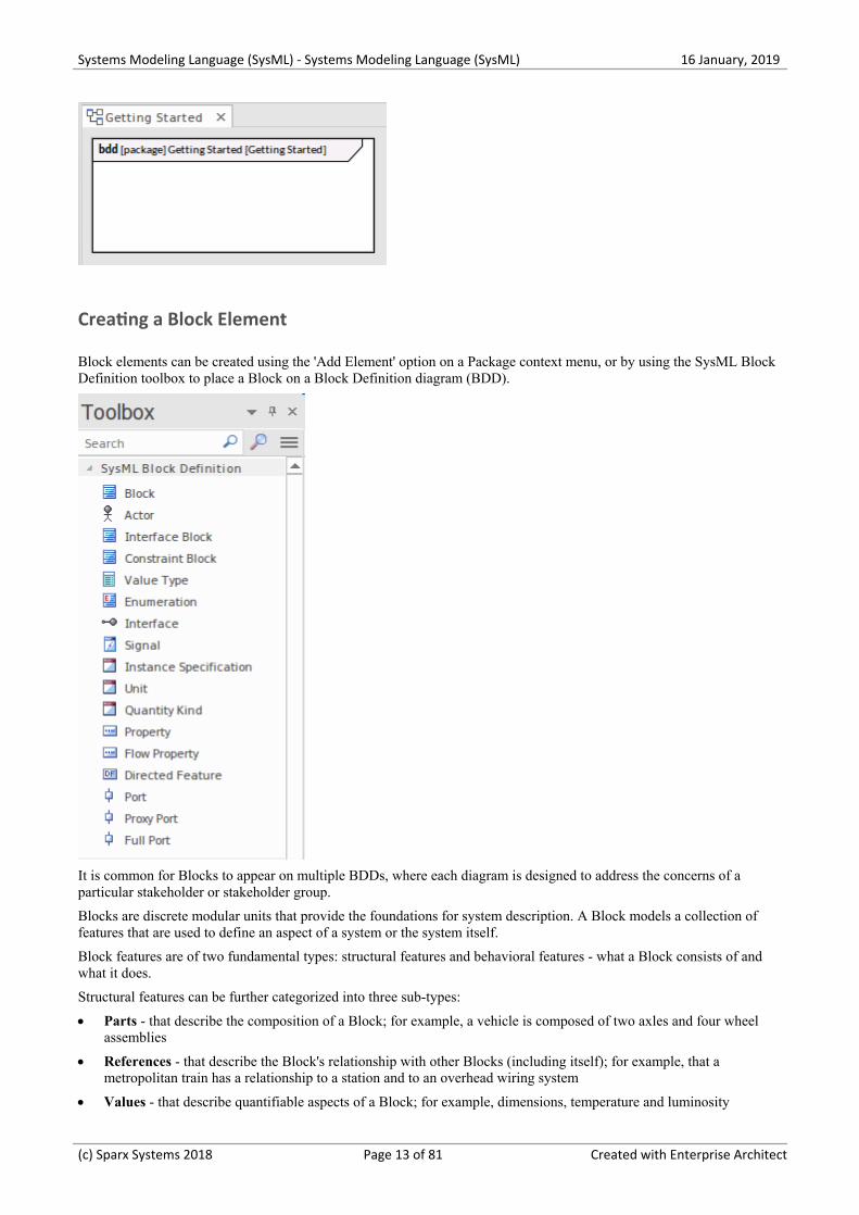
Getting Started with Blocks
A SysML Block Definition diagram is the starting point for describing your system structure. Using Blocks, you canmodel your system hierarchy and the relationships between systems and subsystems.
Setting the Perspective and Workspace
Systems Engineers who are experienced in using Enterprise Architect will generally select a Perspective from theSystems Engineering Perspective Set; typically this will be the SysML Perspective, giving them access to patterns andtoolboxes tailored for creating SysML diagrams such as Block Definition and Internal Block diagrams.
Create a Block Diagram
A Block diagram can be created within a selected Package using any of the following options:
The Project Browser context menu (Right-click on a Package and choose 'Add diagram')·
The Model Wizard (Ctrl+Shift+M)·
The New Diagram dialog (Ctrl+Insert)·
(c) Sparx Systems 2018 Page 12 of 81 Created with Enterprise Architect
Systems Modeling Language (SysML) - Systems Modeling Language (SysML) 16 January, 2019
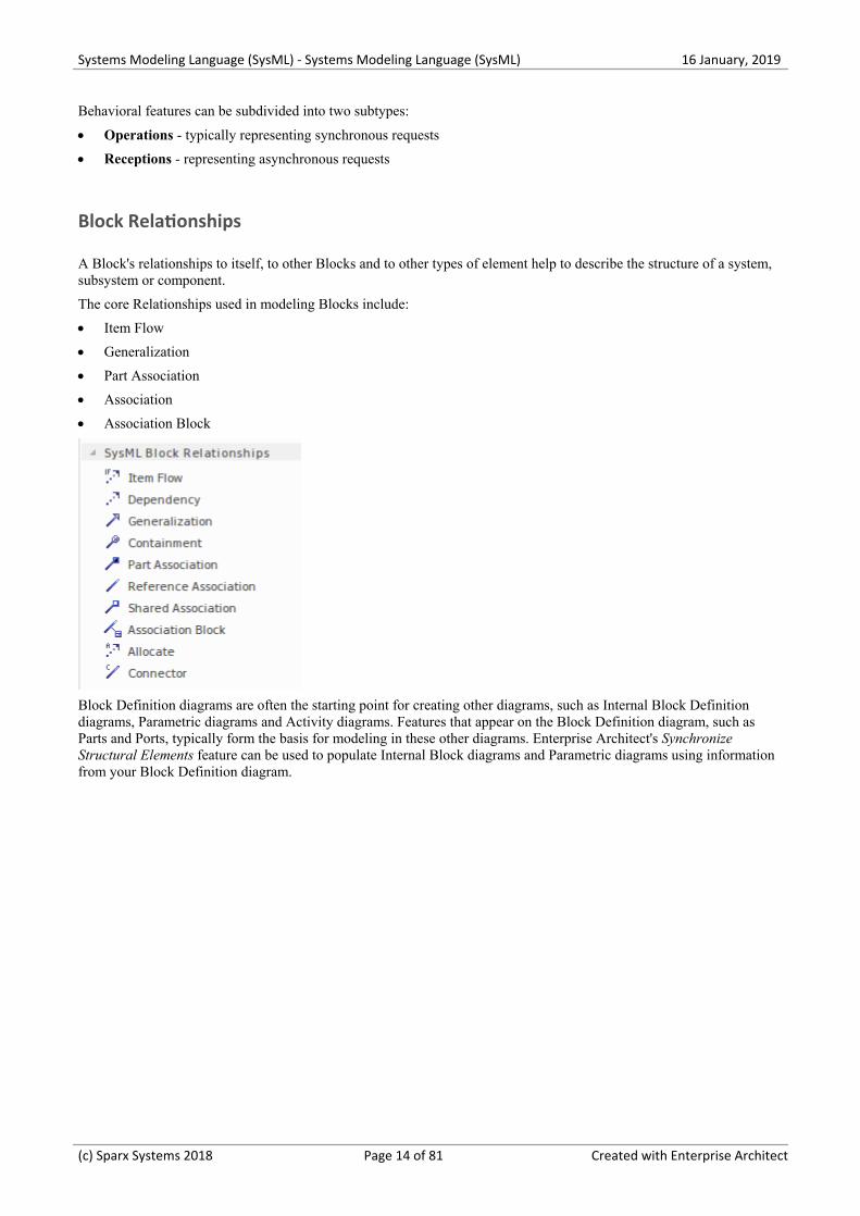
Creating a Block Element
Block elements can be created using the 'Add Element' option on a Package context menu, or by using the SysML BlockDefinition toolbox to place a Block on a Block Definition diagram (BDD).
It is common for Blocks to appear on multiple BDDs, where each diagram is designed to address the concerns of aparticular stakeholder or stakeholder group.
Blocks are discrete modular units that provide the foundations for system description. A Block models a collection offeatures that are used to define an aspect of a system or the system itself.
Block features are of two fundamental types: structural features and behavioral features - what a Block consists of andwhat it does.
Structural features can be further categorized into three sub-types:
Parts - that describe the composition of a Block; for example, a vehicle is composed of two axles and four wheel·assemblies
References - that describe the Block's relationship with other Blocks (including itself); for example, that a·metropolitan train has a relationship to a station and to an overhead wiring system
Values - that describe quantifiable aspects of a Block; for example, dimensions, temperature and luminosity·
(c) Sparx Systems 2018 Page 13 of 81 Created with Enterprise Architect
Systems Modeling Language (SysML) - Systems Modeling Language (SysML) 16 January, 2019
Behavioral features can be subdivided into two subtypes:
Operations - typically representing synchronous requests·
Receptions - representing asynchronous requests·
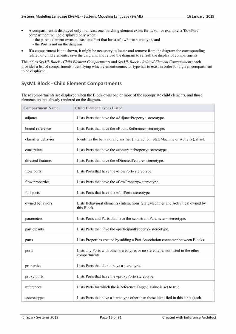
Block Relationships
A Block's relationships to itself, to other Blocks and to other types of element help to describe the structure of a system,subsystem or component.
The core Relationships used in modeling Blocks include:
Item Flow·
Generalization·
Part Association·
Association·
Association Block·
Block Definition diagrams are often the starting point for creating other diagrams, such as Internal Block Definitiondiagrams, Parametric diagrams and Activity diagrams. Features that appear on the Block Definition diagram, such asParts and Ports, typically form the basis for modeling in these other diagrams. Enterprise Architect's SynchronizeStructural Elements feature can be used to populate Internal Block diagrams and Parametric diagrams using informationfrom your Block Definition diagram.
(c) Sparx Systems 2018 Page 14 of 81 Created with Enterprise Architect
Systems Modeling Language (SysML) - Systems Modeling Language (SysML) 16 January, 2019
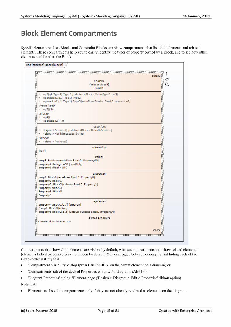
Block Element Compartments
SysML elements such as Blocks and Constraint Blocks can show compartments that list child elements and relatedelements. These compartments help you to easily identify the types of property owned by a Block, and to see how otherelements are linked to the Block.
Compartments that show child elements are visible by default, whereas compartments that show related elements(elements linked by connectors) are hidden by default. You can toggle between displaying and hiding each of thecompartments using the:
'Compartment Visibility' dialog (press Ctrl+Shift+Y on the parent element on a diagram) or·
'Compartments' tab of the docked Properties window for diagrams (Alt+1) or·
'Diagram Properties' dialog, 'Element' page ('Design > Diagram > Edit > Properties' ribbon option)·
Note that:
Elements are listed in compartments only if they are not already rendered as elements on the diagram·
(c) Sparx Systems 2018 Page 15 of 81 Created with Enterprise Architect
Systems Modeling Language (SysML) - Systems Modeling Language (SysML) 16 January, 2019
A compartment is displayed only if at least one matching element exists for it; so, for example, a 'flowPort'·compartment will be displayed only when: - the parent element owns at least one Port that has a «flowPort» stereotype, and - the Port is not on the diagram
If a compartment is not shown, it might be necessary to locate and remove from the diagram the corresponding·related or child elements, save the diagram, and reload the diagram to refresh the display of compartments
The tables SysML Block - Child Element Compartments and SysML Block - Related Element Compartments eachprovides a list of compartments, identifying which element/connector type has to exist in order for a given compartmentto be displayed.
SysML Block - Child Element Compartments
These compartments are displayed when the Block owns one or more of the appropriate child elements, and thoseelements are not already rendered on the diagram.
Compartment Name Child Element Types Listed
adjunct Lists Parts that have the «AdjunctProperty» stereotype.
bound reference Lists Parts that have the «BoundReference» stereotype.
classifier behavior Identifies the behavioral classifier (Interaction, StateMachine or Activity), if set.
constraints Lists Parts that have the «constraintProperty» stereotype.
directed features Lists Parts that have the «DirectedFeature» stereotype.
flow ports Lists Ports that have the «flowPort» stereotype.
flow properties Lists Parts that have the «flowProperty» stereotype.
full ports Lists Ports that have the «fullPort» stereotype.
owned behaviors Lists Behavioral elements (Interactions, StateMachines and Activities) owned bythis Block.
parameters Lists Ports and Parts that have the «constraintParameter» stereotype.
participants Lists Parts that have the «participantProperty» stereotype.
parts Lists Properties created by adding a Part Association connector between Blocks.
ports Lists any Ports with other stereotypes or no stereotype, not listed in the othercompartments.
properties Lists Parts that do not have a stereotype.
proxy ports Lists Ports that have the «proxyPort» stereotype.
references Lists Parts for which the isReference Tagged Value is set to true.
«stereotype» Lists Parts that have a stereotype other than those identified in this table (each
(c) Sparx Systems 2018 Page 16 of 81 Created with Enterprise Architect
Systems Modeling Language (SysML) - Systems Modeling Language (SysML) 16 January, 2019
stereotype has its own compartment with the same name as the stereotype).
values Lists Parts that are typed by a «valueType» element.
SysML Block - Related Element Compartments
These compartments are displayed based on the relationships between a Block and other elements.
Compartment Name Object Displayed
allocatedFrom Identifies the source element of a connector that has the «allocate» stereotype.
allocatedTo Identifies the target element of a connector that has the «allocate» stereotype.
derived Identifies the target element of a connector that has the «derivereqt» stereotype.
derivedFrom Identifies the source element of a connector that has the «derivereqt» stereotype.
master Identifies the target element of a connector that has the «copy» stereotype.
refinedBy Identifies the source element of a connector that has the «refine» stereotype.
satisfiedBy Identifies the source element of a connector that has the «satisfy» stereotype.
tracedTo Identifies the source element of a connector that has the «trace» stereotype.
verifiedBy Identifies the source element of a connector that has the «verify» stereotype.
refines Identifies the target element of a connector that has the «refine» stereotype.
satisfies Identifies the target element of a connector that has the «satisfy» stereotype.
tracedFrom Identifies the target element of a connector that has the «trace» stereotype.
verifies Identifies the target element of a connector that has the «verify» stereotype.
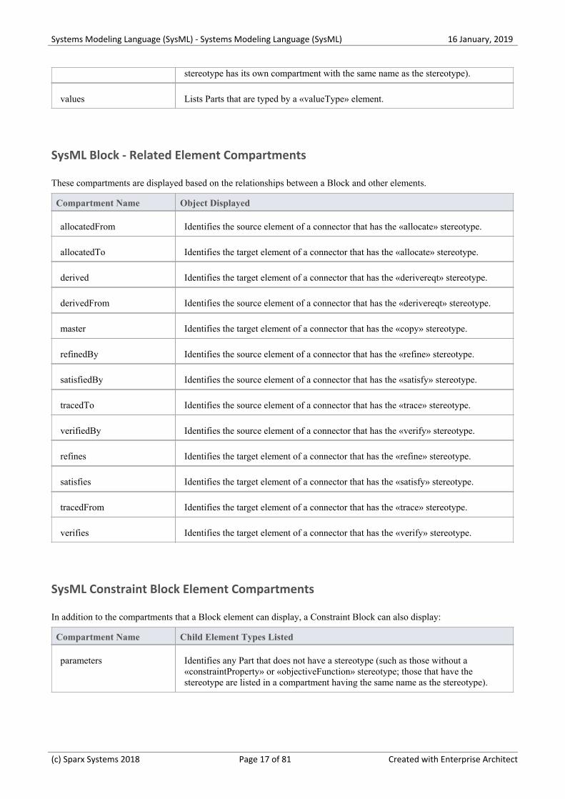
SysML Constraint Block Element Compartments
In addition to the compartments that a Block element can display, a Constraint Block can also display:
Compartment Name Child Element Types Listed
parameters Identifies any Part that does not have a stereotype (such as those without a«constraintProperty» or «objectiveFunction» stereotype; those that have thestereotype are listed in a compartment having the same name as the stereotype).
(c) Sparx Systems 2018 Page 17 of 81 Created with Enterprise Architect
Systems Modeling Language (SysML) - Systems Modeling Language (SysML) 16 January, 2019
Create a Constraint Block from Equations
This feature is available from Enterprise Architect Release 14.1.
When developing an engineering solution, it is a common requirement to reflect factors determined by calculation usingmathematical equations, such as Force = Mass x Acceleration (or f=m*a). The equation is represented by a Constraint,and the elements of the equation - in this case f, m, and a - are the parameters of the constraint.
You can model one or more calculated constraints as a SysML Constraint Block element using the 'Edit ConstraintBlock' dialog, through which you parse the constraints and extract the parameters from each of constraints. You canapply any equations that are appropriate to your model, whether they be international standard formulae or those youhave derived yourself within the domain of your work.
Access
Context menu Right-click on a Constraint Block | Edit ConstraintBlock
Other Diagram Toolbox, SysML Block Definition page | Drag a Constraint Block iconand drop it on a Block Definition diagram
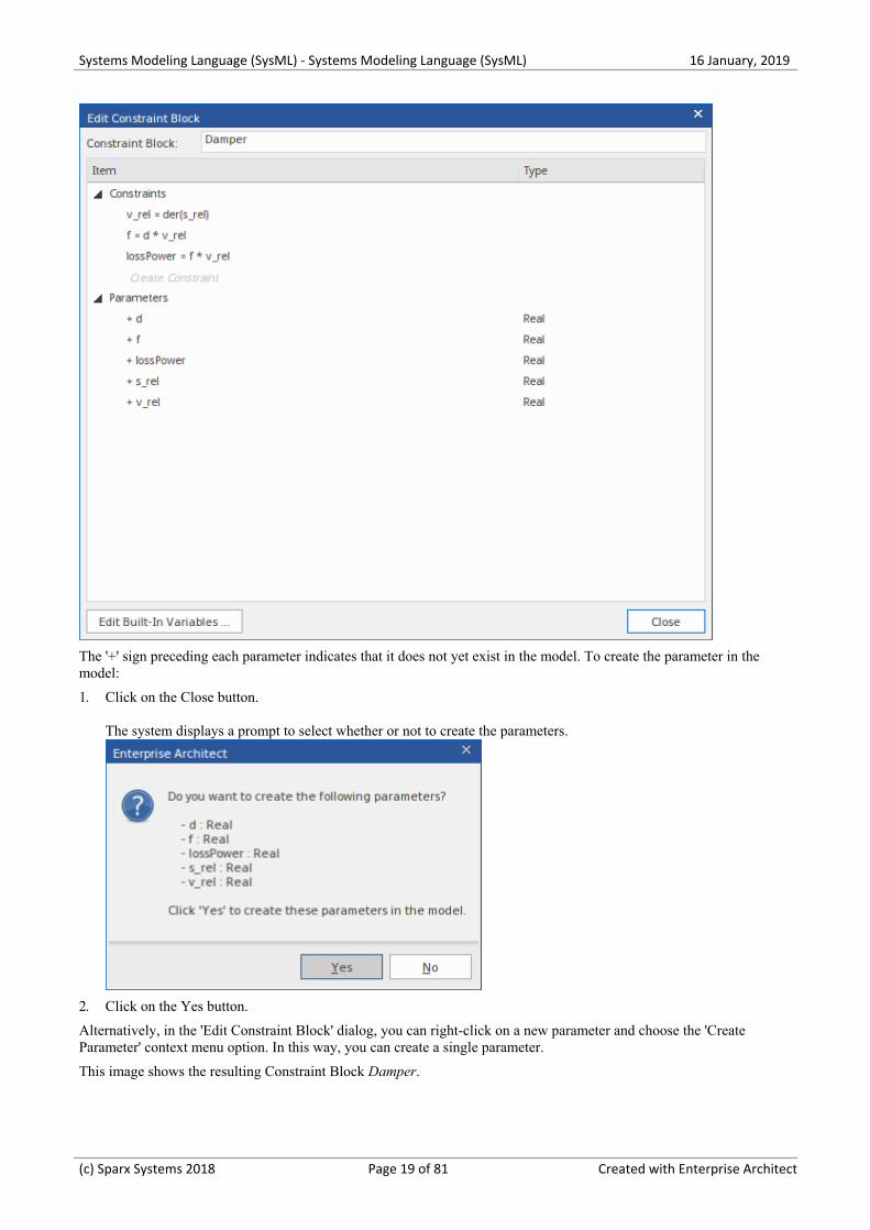
Parse Equations and create Parameters
Suppose we have a Constraint Block named 'Damper', containing these three equations as constraints:
v_rel = der(s_rel)·
f = d * v_rel ('d' is an incorrect symbol for 'Damping Coefficient'; this is deliberate, to allow correction in a later·step)
lossPower = f * v_rel·
The three constraints are entered into the dialog (by overtyping the Create Constraint text) and from these constraintsfive parameters are automatically extracted.
(c) Sparx Systems 2018 Page 18 of 81 Created with Enterprise Architect
Systems Modeling Language (SysML) - Systems Modeling Language (SysML) 16 January, 2019
The '+' sign preceding each parameter indicates that it does not yet exist in the model. To create the parameter in themodel:
Click on the Close button.1.
The system displays a prompt to select whether or not to create the parameters.
Click on the Yes button.2.
Alternatively, in the 'Edit Constraint Block' dialog, you can right-click on a new parameter and choose the 'CreateParameter' context menu option. In this way, you can create a single parameter.
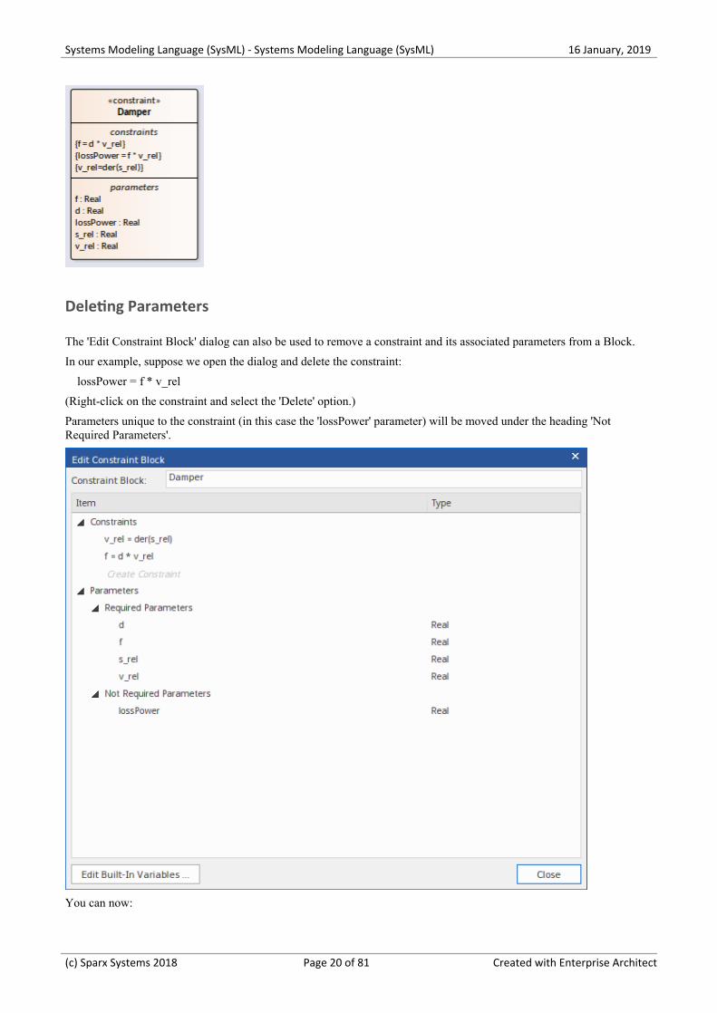
This image shows the resulting Constraint Block Damper.
(c) Sparx Systems 2018 Page 19 of 81 Created with Enterprise Architect
Systems Modeling Language (SysML) - Systems Modeling Language (SysML) 16 January, 2019
Deleting Parameters
The 'Edit Constraint Block' dialog can also be used to remove a constraint and its associated parameters from a Block.
In our example, suppose we open the dialog and delete the constraint:
lossPower = f * v_rel
(Right-click on the constraint and select the 'Delete' option.)
Parameters unique to the constraint (in this case the 'lossPower' parameter) will be moved under the heading 'NotRequired Parameters'.
You can now:
(c) Sparx Systems 2018 Page 20 of 81 Created with Enterprise Architect
Systems Modeling Language (SysML) - Systems Modeling Language (SysML) 16 January, 2019
Right-click on the parameter and choose the 'Delete Parameter' context menu option, or·
Right-click on the 'Not Required Parameters' heading and choose the 'Delete All Not-Required Parameters' option·
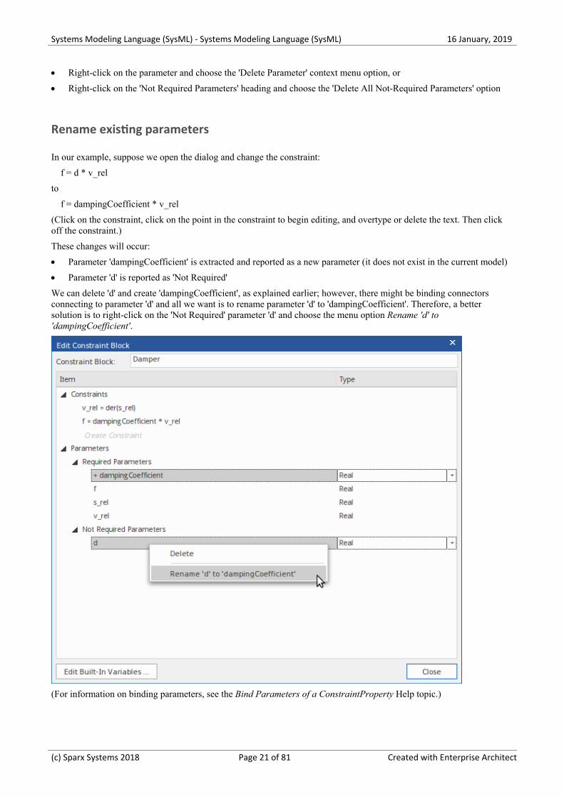
Rename existing parameters
In our example, suppose we open the dialog and change the constraint:
f = d * v_rel
to
f = dampingCoefficient * v_rel
(Click on the constraint, click on the point in the constraint to begin editing, and overtype or delete the text. Then clickoff the constraint.)
These changes will occur:
Parameter 'dampingCoefficient' is extracted and reported as a new parameter (it does not exist in the current model)·
Parameter 'd' is reported as 'Not Required'·
We can delete 'd' and create 'dampingCoefficient', as explained earlier; however, there might be binding connectorsconnecting to parameter 'd' and all we want is to rename parameter 'd' to 'dampingCoefficient'. Therefore, a bettersolution is to right-click on the 'Not Required' parameter 'd' and choose the menu option Rename 'd' to'dampingCoefficient'.
(For information on binding parameters, see the Bind Parameters of a ConstraintProperty Help topic.)
(c) Sparx Systems 2018 Page 21 of 81 Created with Enterprise Architect
Systems Modeling Language (SysML) - Systems Modeling Language (SysML) 16 January, 2019
Mathematical Functions
The equation parser supports the use of mathematical functions (such as der(s_rel), earlier in this topic) within yourconstraint equations. When specifying a function, there should be no spaces between the function name and the openingparenthesis. The function parameters will be extracted as new constraint parameters, but the function name will not.
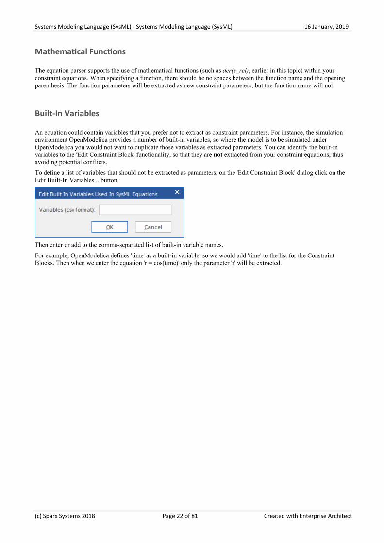
Built-In Variables
An equation could contain variables that you prefer not to extract as constraint parameters. For instance, the simulationenvironment OpenModelica provides a number of built-in variables, so where the model is to be simulated underOpenModelica you would not want to duplicate those variables as extracted parameters. You can identify the built-invariables to the 'Edit Constraint Block' functionality, so that they are not extracted from your constraint equations, thusavoiding potential conflicts.
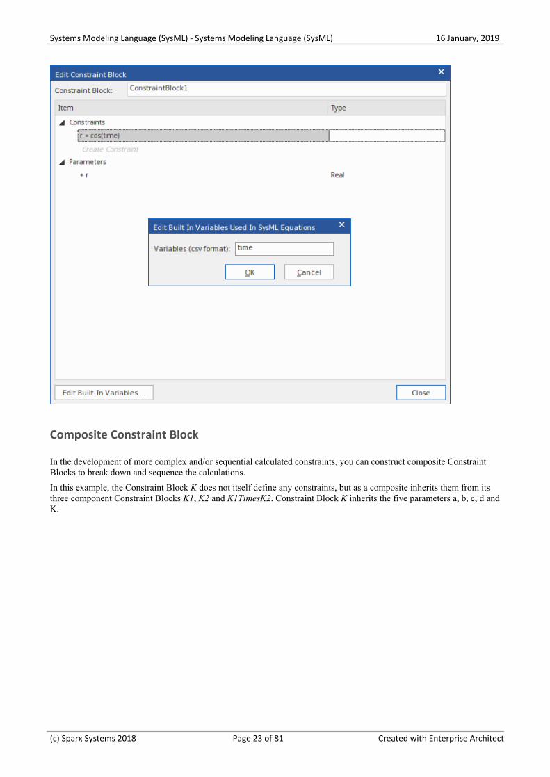
To define a list of variables that should not be extracted as parameters, on the 'Edit Constraint Block' dialog click on theEdit Built-In Variables... button.
Then enter or add to the comma-separated list of built-in variable names.
For example, OpenModelica defines 'time' as a built-in variable, so we would add 'time' to the list for the ConstraintBlocks. Then when we enter the equation 'r = cos(time)' only the parameter 'r' will be extracted.
(c) Sparx Systems 2018 Page 22 of 81 Created with Enterprise Architect
Systems Modeling Language (SysML) - Systems Modeling Language (SysML) 16 January, 2019
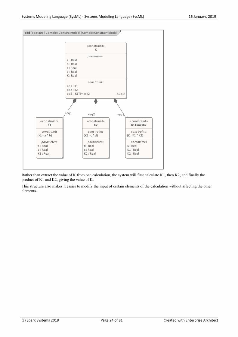
Composite Constraint Block
In the development of more complex and/or sequential calculated constraints, you can construct composite ConstraintBlocks to break down and sequence the calculations.
In this example, the Constraint Block K does not itself define any constraints, but as a composite inherits them from itsthree component Constraint Blocks K1, K2 and K1TimesK2. Constraint Block K inherits the five parameters a, b, c, d andK.
(c) Sparx Systems 2018 Page 23 of 81 Created with Enterprise Architect
Systems Modeling Language (SysML) - Systems Modeling Language (SysML) 16 January, 2019
bdd [package] ComplexConstraintBlock [ComplexConstraintBlock]
«constraint»K
parameters a : Real b : Real c : Real d : Real K : Real
constraints eq1 : K1 eq2 : K2 eq3 : K1TimesK2
«constraint»K1
constraints{K1 = a * b}
parameters a : Real b : Real K1 : Real
«constraint»K2
constraints{K2 = c * d}
parameters d : Real c : Real K2 : Real
«constraint»K1TimesK2
constraints{K = K1 * K2}
parameters K : Real K1 : Real K2 : Real
+eq3+eq1 +eq2
Rather than extract the value of K from one calculation, the system will first calculate K1, then K2, and finally theproduct of K1 and K2, giving the value of K.
This structure also makes it easier to modify the input of certain elements of the calculation without affecting the otherelements.
(c) Sparx Systems 2018 Page 24 of 81 Created with Enterprise Architect
Systems Modeling Language (SysML) - Systems Modeling Language (SysML) 16 January, 2019
Creating Ports and Parts
The set of features that a Block element defines can include Port and Part (or Property) elements. When you initiallycreate a Port or Part on a Block Definition diagram it is rendered as an object on its parent Block element, but the objectis usually then removed from the diagram and represented by a text string in a labeled compartment of the Block.
Access
Other Select or create the required Block Definition diagram, which will open the 'SysMLBlock Definition' pages of the Diagram Toolbox.
Select or create the appropriate Block element in the diagram.
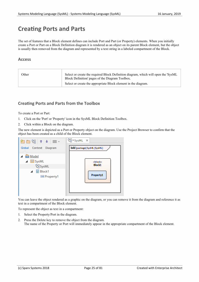
Creating Ports and Parts from the Toolbox
To create a Port or Part:
Click on the 'Port' or 'Property' icon in the SysML Block Definition Toolbox.1.
Click within a Block on the diagram.2.
The new element is depicted as a Port or Property object on the diagram. Use the Project Browser to confirm that theobject has been created as a child of the Block element.
You can leave the object rendered as a graphic on the diagram, or you can remove it from the diagram and reference it astext in a compartment of the Block element.
To represent the object as text in a compartment:
Select the Property/Port in the diagram.1.
Press the Delete key to remove the object from the diagram.2.The name of the Property or Port will immediately appear in the appropriate compartment of the Block element.
(c) Sparx Systems 2018 Page 25 of 81 Created with Enterprise Architect
Systems Modeling Language (SysML) - Systems Modeling Language (SysML) 16 January, 2019
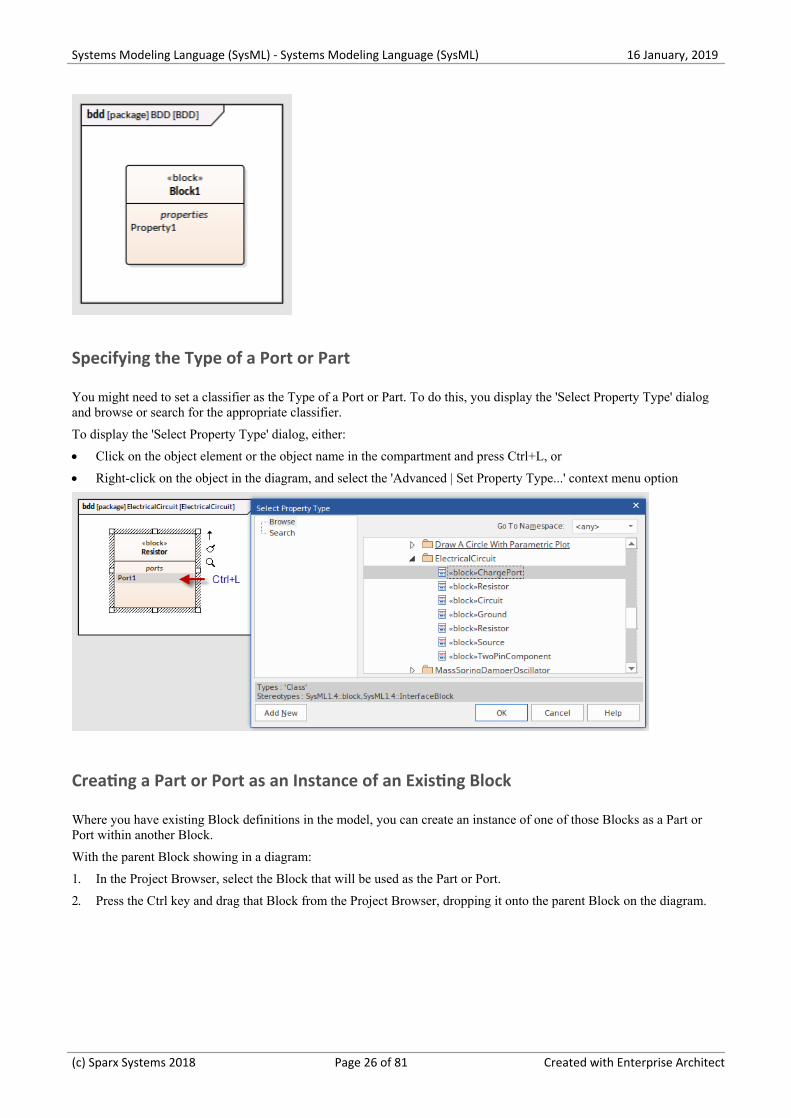
Specifying the Type of a Port or Part
You might need to set a classifier as the Type of a Port or Part. To do this, you display the 'Select Property Type' dialogand browse or search for the appropriate classifier.
To display the 'Select Property Type' dialog, either:
Click on the object element or the object name in the compartment and press Ctrl+L, or·
Right-click on the object in the diagram, and select the 'Advanced | Set Property Type...' context menu option·
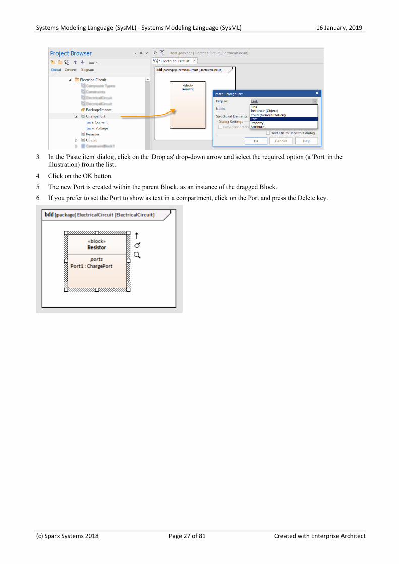
Creating a Part or Port as an Instance of an Existing Block
Where you have existing Block definitions in the model, you can create an instance of one of those Blocks as a Part orPort within another Block.
With the parent Block showing in a diagram:
In the Project Browser, select the Block that will be used as the Part or Port.1.
Press the Ctrl key and drag that Block from the Project Browser, dropping it onto the parent Block on the diagram.2.
(c) Sparx Systems 2018 Page 26 of 81 Created with Enterprise Architect
Systems Modeling Language (SysML) - Systems Modeling Language (SysML) 16 January, 2019
In the 'Paste item' dialog, click on the 'Drop as' drop-down arrow and select the required option (a 'Port' in the3.illustration) from the list.
Click on the OK button.4.
The new Port is created within the parent Block, as an instance of the dragged Block.5.
If you prefer to set the Port to show as text in a compartment, click on the Port and press the Delete key.6.
(c) Sparx Systems 2018 Page 27 of 81 Created with Enterprise Architect
Systems Modeling Language (SysML) - Systems Modeling Language (SysML) 16 January, 2019
Generate Parts From Block Associations
On a SysML Block diagram, the ends of an Association relationship between two Block elements can represent SysMLProperties. If an Association End is navigable, the Property that it represents is owned by the Block element at the otherend of the Association.
In Enterprise Architect you can automatically generate Part elements from the Association Ends to more visiblyrepresent these owned Properties, using any of the methods described here. The Part is bound to the Association End –they represent the same Property, so changing one updates the other, either automatically or at the next synchronization;that is, if you change the Association Source Role name, multiplicity or Aggregation setting, the Part name, multiplicityand isReference setting are updated; if you change the Part details, the Association End properties are updated.
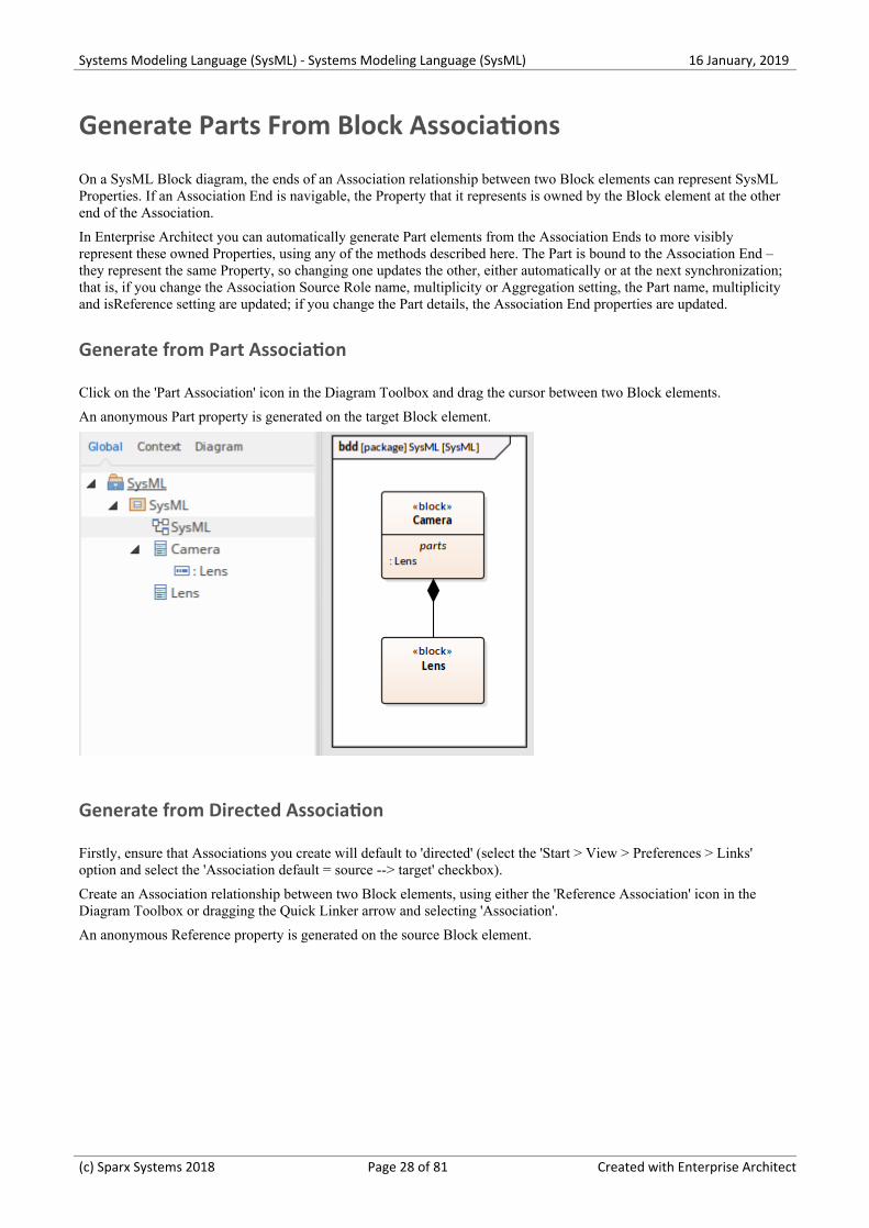
Generate from Part Association
Click on the 'Part Association' icon in the Diagram Toolbox and drag the cursor between two Block elements.
An anonymous Part property is generated on the target Block element.
Generate from Directed Association
Firstly, ensure that Associations you create will default to 'directed' (select the 'Start > View > Preferences > Links'option and select the 'Association default = source --> target' checkbox).
Create an Association relationship between two Block elements, using either the 'Reference Association' icon in theDiagram Toolbox or dragging the Quick Linker arrow and selecting 'Association'.
An anonymous Reference property is generated on the source Block element.
(c) Sparx Systems 2018 Page 28 of 81 Created with Enterprise Architect
Systems Modeling Language (SysML) - Systems Modeling Language (SysML) 16 January, 2019
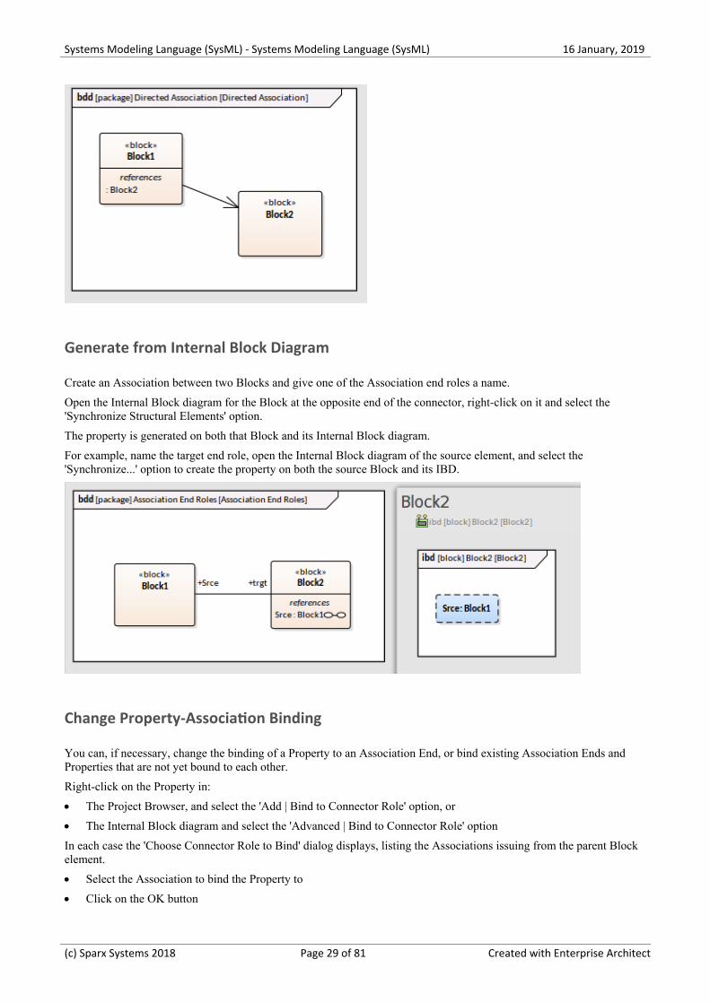
Generate from Internal Block Diagram
Create an Association between two Blocks and give one of the Association end roles a name.
Open the Internal Block diagram for the Block at the opposite end of the connector, right-click on it and select the'Synchronize Structural Elements' option.
The property is generated on both that Block and its Internal Block diagram.
For example, name the target end role, open the Internal Block diagram of the source element, and select the'Synchronize...' option to create the property on both the source Block and its IBD.
Change Property-Association Binding
You can, if necessary, change the binding of a Property to an Association End, or bind existing Association Ends andProperties that are not yet bound to each other.
Right-click on the Property in:
The Project Browser, and select the 'Add | Bind to Connector Role' option, or·
The Internal Block diagram and select the 'Advanced | Bind to Connector Role' option·
In each case the 'Choose Connector Role to Bind' dialog displays, listing the Associations issuing from the parent Blockelement.
Select the Association to bind the Property to·
Click on the OK button·
(c) Sparx Systems 2018 Page 29 of 81 Created with Enterprise Architect
Systems Modeling Language (SysML) - Systems Modeling Language (SysML) 16 January, 2019
If you subsequently delete an Association that is bound to a Property, when you save the diagram you are prompted toconfirm whether to also delete the Property or keep it, unbound to a connector.
If the Property element is locked, it cannot be deleted.
(c) Sparx Systems 2018 Page 30 of 81 Created with Enterprise Architect
Systems Modeling Language (SysML) - Systems Modeling Language (SysML) 16 January, 2019
Nested Ports in SysML
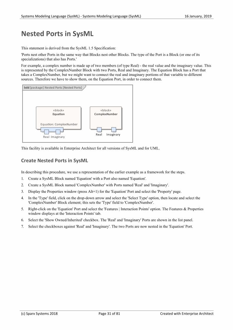
This statement is derived from the SysML 1.5 Specification:
'Ports nest other Ports in the same way that Blocks nest other Blocks. The type of the Port is a Block (or one of itsspecializations) that also has Ports.'
For example, a complex number is made up of two members (of type Real) - the real value and the imaginary value. Thisis represented by the ComplexNumber Block with two Ports, Real and Imaginary. The Equation Block has a Port thattakes a ComplexNumber, but we might want to connect the real and imaginary portions of that variable to differentsources. Therefore we have to show them, on the Equation Port, in order to connect them.
bdd [package] Nested Ports [Nested Ports]
Equation: ComplexNumber
«block»Equation
Equation: ComplexNumber
Real ImaginaryReal Imaginary
«block»ComplexNumber
Real Imaginary
This facility is available in Enterprise Architect for all versions of SysML and for UML.
Create Nested Ports in SysML
In describing this procedure, we use a representation of the earlier example as a framework for the steps.
Create a SysML Block named 'Equation' with a Port also named 'Equation'.1.
Create a SysML Block named 'ComplexNumber' with Ports named 'Real' and 'Imaginary'.2.
Display the Properties window (press Alt+1) for the 'Equation' Port and select the 'Property' page.3.
In the 'Type' field, click on the drop-down arrow and select the 'Select Type' option, then locate and select the4.'ComplexNumber' Block element; this sets the 'Type' field to 'ComplexNumber'.
Right-click on the 'Equation' Port and select the 'Features | Interaction Points' option. The Features & Properties5.window displays at the 'Interaction Points' tab.
Select the 'Show Owned/Inherited' checkbox. The 'Real' and 'Imaginary' Ports are shown in the list panel.6.
Select the checkboxes against 'Real' and 'Imaginary'. The two Ports are now nested in the 'Equation' Port.7.
(c) Sparx Systems 2018 Page 31 of 81 Created with Enterprise Architect
Systems Modeling Language (SysML) - Systems Modeling Language (SysML) 16 January, 2019
A SysML Operational Domain Model
Systems engineering is an interdisciplinary field of engineering that takes a whole-of-system view of a problem and itssolution. The operational domain model is a central part of any model-based approach and describes the system in thecontext of its environment. This includes the humans that are intended to operate and interact with the system, externalobjects that might influence the system, and environmental elements that could impact the system. The operationaldomain model is a useful starting point to get an overview of a system and how it will operate.
Enterprise Architect provides a range of features that help the engineer to construct an operational domain model,including standard SysML Block definition and Internal Block diagrams, and the ability to include pictorialrepresentations of elements that make the diagrams more compelling. The elements can also be hyper-linked, enablingthe viewer to use a diagram as a launching pad to more detailed models and diagrams.
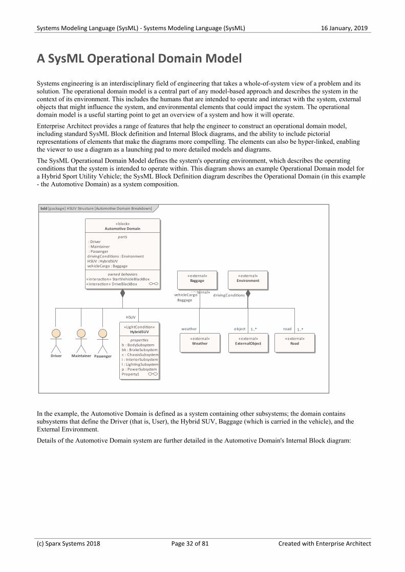
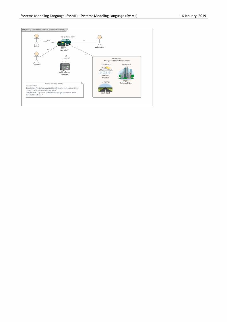
The SysML Operational Domain Model defines the system's operating environment, which describes the operatingconditions that the system is intended to operate within. This diagram shows an example Operational Domain model fora Hybrid Sport Utility Vehicle; the SysML Block Definition diagram describes the Operational Domain (in this example- the Automotive Domain) as a system composition.
bdd [package] HSUV Structure [Automotive Domain Breakdown]
«block»Automotive Domain
parts : Driver : Maintainer : Passenger drivingConditions : Environment HSUV : HybridSUV vehicleCargo : Baggage
owned behaviors«interaction» StartVehicleBlackBox«interaction» DriveBlackBox
Driver Maintainer Passenger
«LightCondition»HybridSUV
properties b : BodySubsystem bk : BrakeSubsystem c : ChassisSubsystem i : InteriorSubsystem l : LightingSubsystem p : PowerSubsystem Property1
«external»Environment
«external»
«external»Baggage
Baggage
«external»ExternalObject
«external»Road
«external»Weather
weather
vehicleCargo
object 1..*
drivingConditions
road 1..*
HSUV
In the example, the Automotive Domain is defined as a system containing other subsystems; the domain containssubsystems that define the Driver (that is, User), the Hybrid SUV, Baggage (which is carried in the vehicle), and theExternal Environment.
Details of the Automotive Domain system are further detailed in the Automotive Domain's Internal Block diagram:
(c) Sparx Systems 2018 Page 32 of 81 Created with Enterprise Architect
Systems Modeling Language (SysML) - Systems Modeling Language (SysML) 16 January, 2019
ibd [block] Automotive Domain [AutomotiveDomain]
«external»drivingConditions: Environment
Driver
Passenger
Maintainer
object: ExternalObject
«external»
HSUV: HybridSUV
«L ightCondition»
weather: Weather
«external»
road: Road
«external»
vehicleCargo:Baggage
«external»
«diagramDescription»version=”0.1"description=”Initial concept to identify top level domain entities"reference=”Ops Concept Description”completeness=”partial. Does not include gas pump and otherexternal interfaces.”
x4:
x2:
x5:x1:
x3:
In the example, the Automotive Domain system's detailed composition shows how the Hybrid SUV and other subsystemsfit together to form the Automotive Domain; it also describes the binding relationships between the parts, which definehow the parts are functionally bound to one another.
(c) Sparx Systems 2018 Page 33 of 81 Created with Enterprise Architect
Systems Modeling Language (SysML) - Systems Modeling Language (SysML) 16 January, 2019
Parametric Diagrams
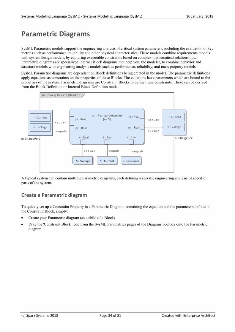
SysML Parametric models support the engineering analysis of critical system parameters, including the evaluation of keymetrics such as performance, reliability and other physical characteristics. These models combine requirements modelswith system design models, by capturing executable constraints based on complex mathematical relationships.Parametric diagrams are specialized Internal Block diagrams that help you, the modeler, to combine behavior andstructure models with engineering analysis models such as performance, reliability, and mass property models.
SysML Parametric diagrams are dependant on Block definitions being created in the model. The parametric definitionsapply equations as constraints on the properties of these Blocks. The equations have parameters which are bound to theproperties of the system. Parametric diagrams use Constraint Blocks to define these constraints. These can be derivedfrom the Block Definition or Internal Block Definition model.
n: ChargePortp: ChargePort
par [block] Resistor [Resistor]
n: ChargePortp: ChargePort
r: Resistance
rc : ResistorConstraint{v=r*i}
pv : Real
pi : Real
nv : Real
ni : Real
v : Real i : Real r : Real
^v: Voltage ^i: Current
v : Voltage
i : Current
v : Voltage
i : Current
«equal»
«equal»
«equal»«equal»
«equal» «equal»
«equal»
A typical system can contain multiple Parametric diagrams, each defining a specific engineering analysis of specificparts of the system.
Create a Parametric diagram
To quickly set up a Constraint Property in a Parametric Diagram, containing the equation and the parameters defined inthe Constraint Block, simply:
Create your Parametric diagram (as a child of a Block)·
Drag the 'Constraint Block' icon from the SysML Parametrics pages of the Diagram Toolbox onto the Parametric·diagram
(c) Sparx Systems 2018 Page 34 of 81 Created with Enterprise Architect
Systems Modeling Language (SysML) - Systems Modeling Language (SysML) 16 January, 2019
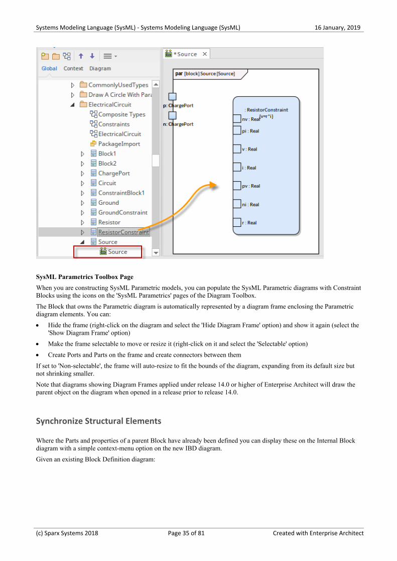
SysML Parametrics Toolbox Page
When you are constructing SysML Parametric models, you can populate the SysML Parametric diagrams with ConstraintBlocks using the icons on the 'SysML Parametrics' pages of the Diagram Toolbox.
The Block that owns the Parametric diagram is automatically represented by a diagram frame enclosing the Parametricdiagram elements. You can:
Hide the frame (right-click on the diagram and select the 'Hide Diagram Frame' option) and show it again (select the·'Show Diagram Frame' option)
Make the frame selectable to move or resize it (right-click on it and select the 'Selectable' option)·
Create Ports and Parts on the frame and create connectors between them·
If set to 'Non-selectable', the frame will auto-resize to fit the bounds of the diagram, expanding from its default size butnot shrinking smaller.
Note that diagrams showing Diagram Frames applied under release 14.0 or higher of Enterprise Architect will draw theparent object on the diagram when opened in a release prior to release 14.0.
Synchronize Structural Elements
Where the Parts and properties of a parent Block have already been defined you can display these on the Internal Blockdiagram with a simple context-menu option on the new IBD diagram.
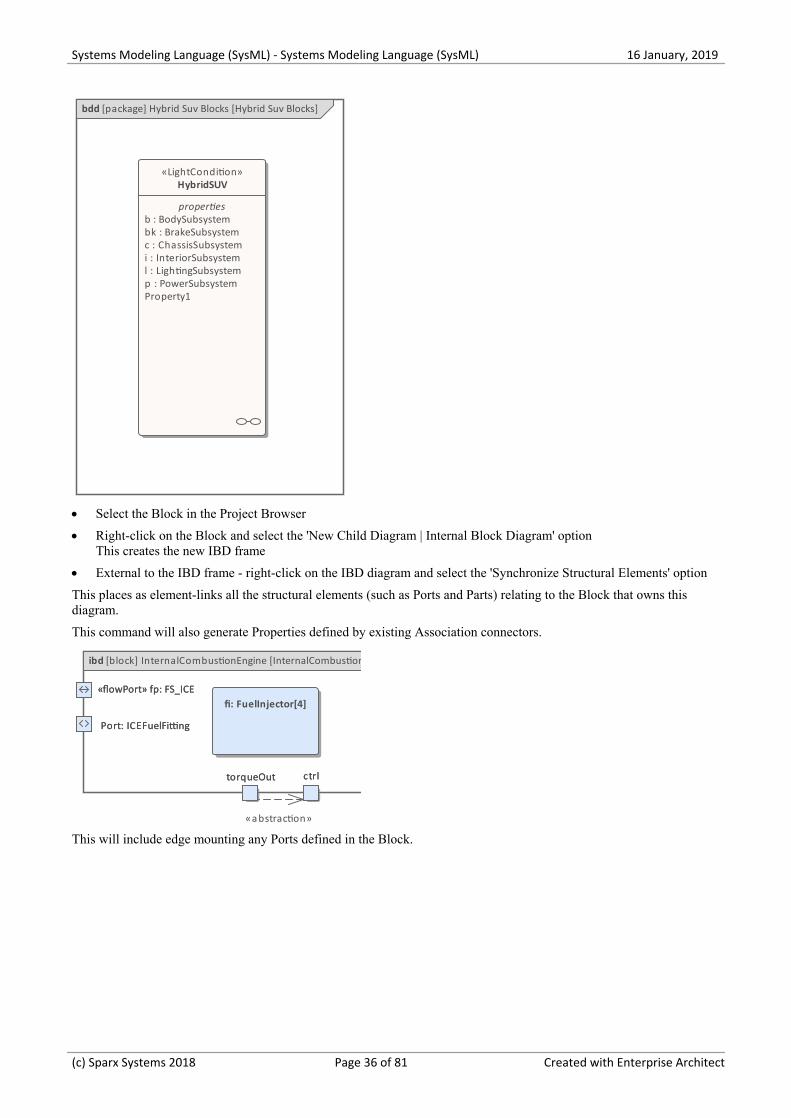
Given an existing Block Definition diagram:
(c) Sparx Systems 2018 Page 35 of 81 Created with Enterprise Architect
Systems Modeling Language (SysML) - Systems Modeling Language (SysML) 16 January, 2019
bdd [package] Hybrid Suv Blocks [Hybrid Suv Blocks]
«LightCondition»HybridSUV
properties b : BodySubsystem bk : BrakeSubsystem c : ChassisSubsystem i : InteriorSubsystem l : LightingSubsystem p : PowerSubsystem Property1
Select the Block in the Project Browser·
Right-click on the Block and select the 'New Child Diagram | Internal Block Diagram' option·This creates the new IBD frame
External to the IBD frame - right-click on the IBD diagram and select the 'Synchronize Structural Elements' option·
This places as element-links all the structural elements (such as Ports and Parts) relating to the Block that owns thisdiagram.
This command will also generate Properties defined by existing Association connectors.
torqueOut
Port: ICEFuelFitting
«flowPort» fp: FS_ICE
ctrl
ibd [block] InternalCombustionEngine [InternalCombustionEngine]
torqueOut
Port: ICEFuelFitting
«flowPort» fp: FS_ICE
ctrl
fi: FuelInjector[4]
«abstraction»
This will include edge mounting any Ports defined in the Block.
(c) Sparx Systems 2018 Page 36 of 81 Created with Enterprise Architect
Systems Modeling Language (SysML) - Systems Modeling Language (SysML) 16 January, 2019
Parametric Diagram Modeling Assistant
This feature is available from Enterprise Architect Release 14.1.
Enterprise Architect provides a set of convenient tools to help you create ConstraintBlocks and parameters, by parsingmathematical equations to create parameter binding connectors and using a hierarchical element picker to createembedded elements.
Resizing Ports
Having created a Port on your Parametric diagram, you can resize it to accommodate any text it contains. You have twooptions:
Right-Click - Advanced | Port Size Customizable·
Right-Click - Advanced |Bind to Connector Role·
(c) Sparx Systems 2018 Page 37 of 81 Created with Enterprise Architect
Systems Modeling Language (SysML) - Systems Modeling Language (SysML) 16 January, 2019
Bind Parameters of a ConstraintProperty
Access
Context menu In a diagram, click on an existing Constraint Property | Edit Constraint Property...
Other In Project Browser | Drag a Constraint Block and drop it on a Parametric diagram
A Constraint Property with all the parameters will be created
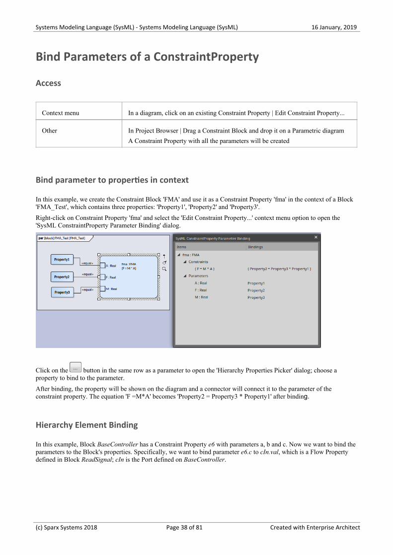
Bind parameter to properties in context
In this example, we create the Constraint Block 'FMA' and use it as a Constraint Property 'fma' in the context of a Block'FMA_Test', which contains three properties: 'Property1', 'Property2' and 'Property3'.
Right-click on Constraint Property 'fma' and select the 'Edit Constraint Property...' context menu option to open the'SysML ConstraintProperty Parameter Binding' dialog.
Click on the button in the same row as a parameter to open the 'Hierarchy Properties Picker' dialog; choose aproperty to bind to the parameter.
After binding, the property will be shown on the diagram and a connector will connect it to the parameter of theconstraint property. The equation 'F =M*A' becomes 'Property2 = Property3 * Property1' after binding.
Hierarchy Element Binding
In this example, Block BaseController has a Constraint Property e6 with parameters a, b and c. Now we want to bind theparameters to the Block's properties. Specifically, we want to bind parameter e6.c to cIn.val, which is a Flow Propertydefined in Block ReadSignal; cIn is the Port defined on BaseController.
(c) Sparx Systems 2018 Page 38 of 81 Created with Enterprise Architect
Systems Modeling Language (SysML) - Systems Modeling Language (SysML) 16 January, 2019
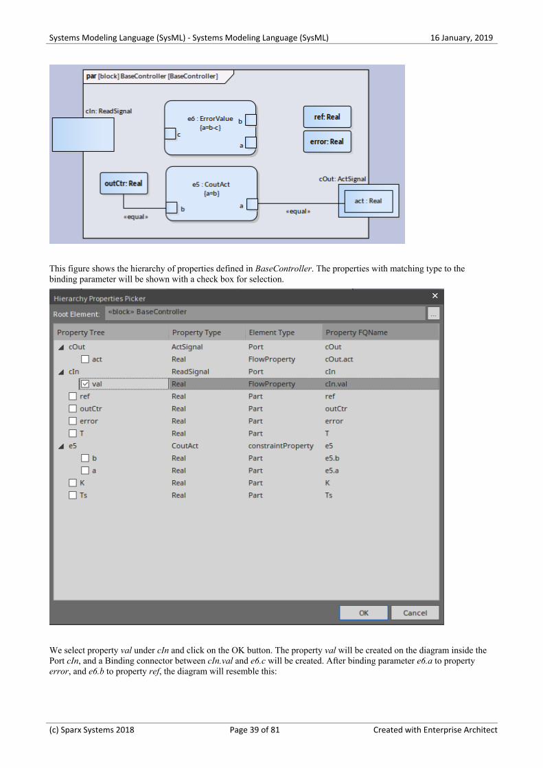
This figure shows the hierarchy of properties defined in BaseController. The properties with matching type to thebinding parameter will be shown with a check box for selection.
We select property val under cIn and click on the OK button. The property val will be created on the diagram inside thePort cIn, and a Binding connector between cIn.val and e6.c will be created. After binding parameter e6.a to propertyerror, and e6.b to property ref, the diagram will resemble this:
(c) Sparx Systems 2018 Page 39 of 81 Created with Enterprise Architect
Systems Modeling Language (SysML) - Systems Modeling Language (SysML) 16 January, 2019
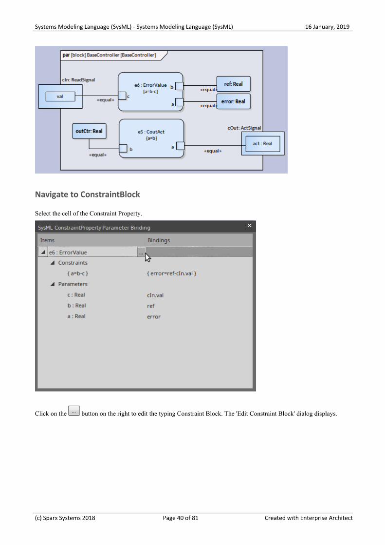
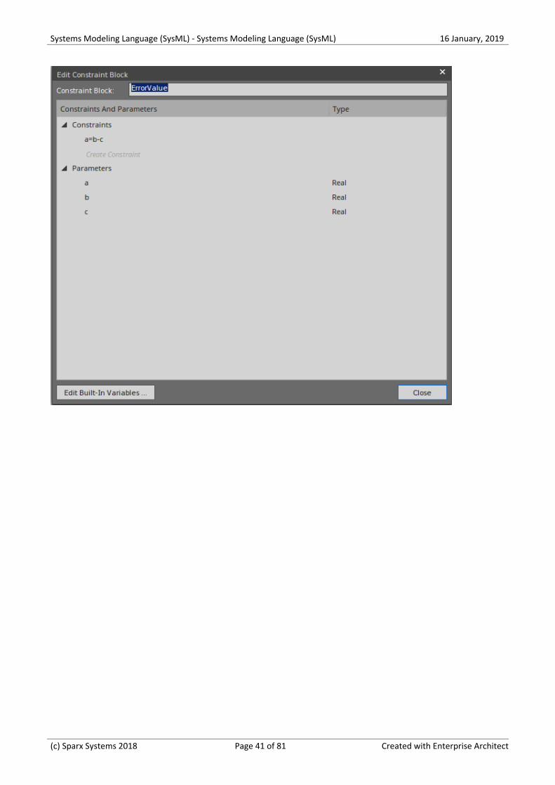
Navigate to ConstraintBlock
Select the cell of the Constraint Property.
Click on the button on the right to edit the typing Constraint Block. The 'Edit Constraint Block' dialog displays.
(c) Sparx Systems 2018 Page 40 of 81 Created with Enterprise Architect
Systems Modeling Language (SysML) - Systems Modeling Language (SysML) 16 January, 2019
(c) Sparx Systems 2018 Page 41 of 81 Created with Enterprise Architect
Systems Modeling Language (SysML) - Systems Modeling Language (SysML) 16 January, 2019
Compose System Design
The systems engineering language has a strong focus on design. Once the requirements have been elicited, modeled andanalyzed, the attention of the engineer turns to design. The systems are typically complex and must be broken down intoa number of Subsystems that will interact with each other through known and published interfaces. The decomposition ofthe system is modeled using a Block Definition diagram displaying the subsystems, which in turn can be furtherdecomposed. These subsystems can be traced back to the requirements and then to the stakeholders who own therequirements.
A Block Definition diagram can be created in Enterprise Architect to model the decomposition of a system into ahierarchy of subsystems using, the composition association. Subsystems can be hyper-linked to more detailed diagrams,which allow the viewer to click through from the system level through to all its constituent parts. The subsystems canalso be linked back to the requirements they are implementing.
The SysML Design Model
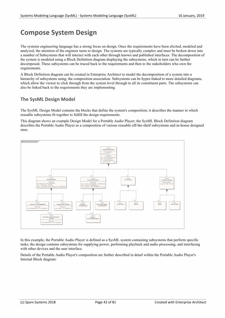
The SysML Design Model contains the blocks that define the system's composition; it describes the manner in whichreusable subsystems fit together to fulfill the design requirements.
This diagram shows an example Design Model for a Portable Audio Player; the SysML Block Definition diagramdescribes the Portable Audio Player as a composition of various reusable off-the-shelf subsystems and in-house designedones.
bdd [Package] Design [Design]
«block»Portable Audio Player
flow properties inout rstr : RS232
«property» proc : Processing Subsystem pwr : PowerSubsystem tr : Transport Subsystem ui : User Interface
«block»PowerSubsystem
«property» bat : Panasonic Li-Ion CGR18650AF chrg : Charging Unit - ADP2291 pmon : Li-Ion Battery Monitoring System - AD7230
«block»Transport Subsystem
flow properties inout utr : USB - PL-2528
«block»USB - PL-2528
«block»Processing Subsystem
«property» codec : Codec with Amplifier - TLV320AIC3107 cpu : Processor - TMS320VC5507 mem : Memory - MT42L32M64D2KH-25
«block»Codec with Amplifier -
TLV320AIC3107
«block»Processor -
TMS320VC5507
«block»Panasonic Li-Ion CGR18650AF
flow ports inout chargeIndicator : FS_ChargeFlow
«block»Charging Unit - ADP2291
flow ports inout charger : FS_ChargeFlow
«block»Li-Ion Battery Monitoring System -
AD7230
flow ports inout chargeMonitor : FS_ChargeFlow
«block»User Interface
«block»Touch-screen
«block»Memory -
MT42L32M64D2KH-25
«block»Buttons
«block»RS232
chrg rstrcodec
tr
utr
mem
proc
btnbat cpu
ui
tscr
pwr
pmon
In this example, the Portable Audio Player is defined as a SysML system containing subsystems that perform specifictasks; the design contains subsystems for supplying power, performing playback and audio processing, and interfacingwith other devices and the user interface.
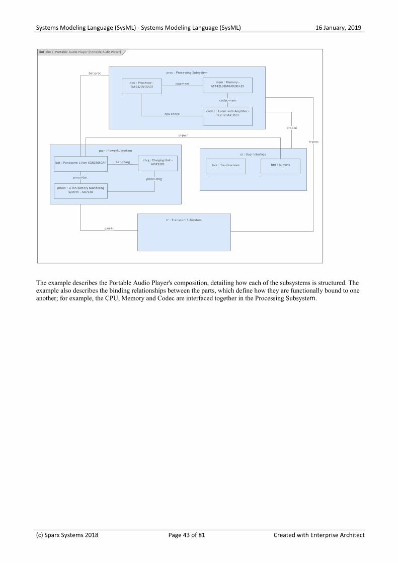
Details of the Portable Audio Player's composition are further described in detail within the Portable Audio Player'sInternal Block diagram:
(c) Sparx Systems 2018 Page 42 of 81 Created with Enterprise Architect
Systems Modeling Language (SysML) - Systems Modeling Language (SysML) 16 January, 2019
ibd [Block] Portable Audio Player [Portable Audio Player]
pwr : PowerSubsystemui : User Interface
tr : Transport Subsystem
proc : Processing Subsystem
cpu : Processor -TMS320VC5507
codec : Codec with Amplifier -TLV320AIC3107
mem : Memory -MT42L32M64D2KH-25
tscr : Touch-screen btn : Buttonsbat : Panasonic Li-Ion CGR18650AF
chrg : Charging Unit -ADP2291
pmon : Li-Ion Battery MonitoringSystem - AD7230
ui-pwr
bat-proc
pwr-tr
pmon-chrg
cpu-mem
pmon-bat
proc-ui
cpu-codec
tr-proc
bat-charg
codec-mem
The example describes the Portable Audio Player's composition, detailing how each of the subsystems is structured. Theexample also describes the binding relationships between the parts, which define how they are functionally bound to oneanother; for example, the CPU, Memory and Codec are interfaced together in the Processing Subsystem.
(c) Sparx Systems 2018 Page 43 of 81 Created with Enterprise Architect
Systems Modeling Language (SysML) - Systems Modeling Language (SysML) 16 January, 2019
Create Reusable Subsystems
Model-based Systems Engineering provides the flexibility and expressiveness to define complex systems quickly andeffectively, by reusing common entities across design projects. Before the model based approach became prevalent,systems were defined using document based methods with little opportunity for re-use. The SysML contains a series ofreusable libraries such as the SI Definitions and the SI Value Types, but also supports a modeler in creating additionaldomain or technology-specific libraries that could be reused within an organization, or published for wider use by acommunity of users or an entire industry.
Enterprise Architect provides a range of functionality to assist in creating, discovering, visualizing and reusing librariesof elements such as subsystems, parametric constraints, common data types, common value types, dimensions and units.The Reusable Asset Service could be used to store these assets in order to provide a canonical set of libraries governedby the respective standards agencies.
SysML Design Model
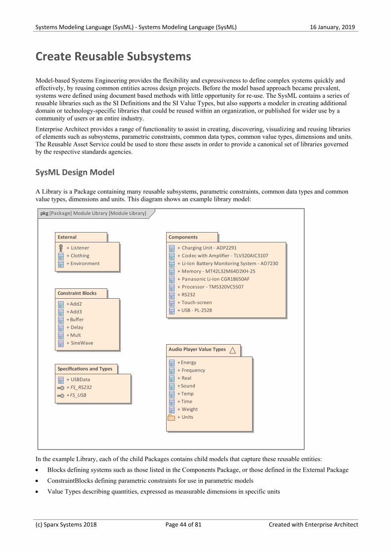
A Library is a Package containing many reusable subsystems, parametric constraints, common data types and commonvalue types, dimensions and units. This diagram shows an example library model:
pkg [Package] Module Library [Module Library]
External
+ Listener+ Clothing+ Environment
Constraint Blocks
+ Add2+ Add3+ Buffer+ Delay+ Mult+ SineWave
Components
+ Charging Unit - ADP2291+ Codec with Amplifier - TLV320AIC3107+ Li-Ion Battery Monitoring System - AD7230+ Memory - MT42L32M64D2KH-25+ Panasonic Li-Ion CGR18650AF+ Processor - TMS320VC5507+ RS232+ Touch-screen+ USB - PL-2528
Audio Player Value Types
+ Energy+ Frequency+ Real+ Sound+ Temp+ Time+ Weight+ Units
Specifications and Types
+ USBData+ FS_RS232+ FS_USB
In the example Library, each of the child Packages contains child models that capture these reusable entities:
Blocks defining systems such as those listed in the Components Package, or those defined in the External Package·
ConstraintBlocks defining parametric constraints for use in parametric models·
Value Types describing quantities, expressed as measurable dimensions in specific units·
(c) Sparx Systems 2018 Page 44 of 81 Created with Enterprise Architect
Systems Modeling Language (SysML) - Systems Modeling Language (SysML) 16 January, 2019
Data Types and Flow Specifications describing data structures and Flows·
(c) Sparx Systems 2018 Page 45 of 81 Created with Enterprise Architect
Systems Modeling Language (SysML) - Systems Modeling Language (SysML) 16 January, 2019
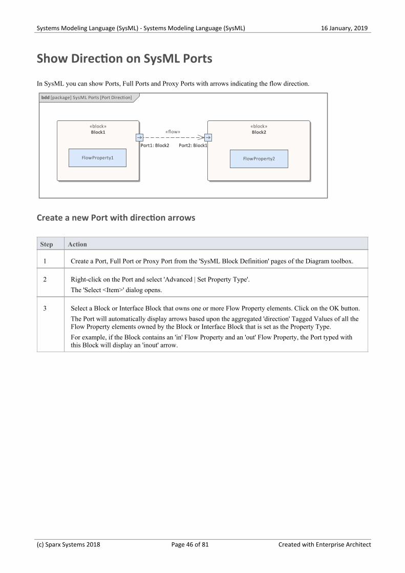
Show Direction on SysML Ports
In SysML you can show Ports, Full Ports and Proxy Ports with arrows indicating the flow direction.
bdd [package] SysML Ports [Port Direction]
Port1: Block2
«block»Block1
Port1: Block2 Port2: Block1
«block»Block2
Port2: Block1
FlowProperty1 FlowProperty2
«flow»
Create a new Port with direction arrows
Step Action
1 Create a Port, Full Port or Proxy Port from the 'SysML Block Definition' pages of the Diagram toolbox.
2 Right-click on the Port and select 'Advanced | Set Property Type'.
The 'Select <Item>' dialog opens.
3 Select a Block or Interface Block that owns one or more Flow Property elements. Click on the OK button.
The Port will automatically display arrows based upon the aggregated 'direction' Tagged Values of all theFlow Property elements owned by the Block or Interface Block that is set as the Property Type.
For example, if the Block contains an 'in' Flow Property and an 'out' Flow Property, the Port typed withthis Block will display an 'inout' arrow.
(c) Sparx Systems 2018 Page 46 of 81 Created with Enterprise Architect

Systems Modeling Language (SysML) - Systems Modeling Language (SysML) 16 January, 2019
SysML Toolboxes
Enterprise Architect's support for SysML provides Diagram Toolbox pages for the nine types of SysML diagram, whichyou can access through the 'Find Toolbox Item' dialog. If you enable SysML as the active technology, you can also openthe SysML Toolbox pages by default.
These sets of Toolbox pages are available:
'Activity' contains the constructs required to construct SysML Activity models·
'Block Definition' contains the constructs required to design SysML Blocks, Constraint Blocks, data and value types·
'Interaction' contains the constructs required to construct SysML interactions and Sequence diagrams·
'Internal Block' contains the constructs required to design SysML Block compositions within Internal Block·diagrams
'Model Elements' contains the constructs required to build SysML models, Package structures and views·
'Parametrics' contains the constructs required to construct SysML Parametric diagrams using constraint blocks·
'Requirements' contains the constructs required to build SysML Requirements models·
'StateMachine' contains the constructs required to build SysML StateMachines·
'Use Case' contains the constructs required to build SysML Use Case models·
With the 'Model Elements' pages there is a set of SysML Common elements and relationships; these are also providedwith the other 'SysML' Toolbox pages if the active technology is set on the Default Tools toolbar to 'SysML 1.1', 'SysML1.2', 'SysML 1.3', 'SysML 1.4' or 'SysML 1.5'.
For details, see the Help Topic for each set of SysML Toolbox pages.
(c) Sparx Systems 2018 Page 47 of 81 Created with Enterprise Architect
Systems Modeling Language (SysML) - Systems Modeling Language (SysML) 16 January, 2019
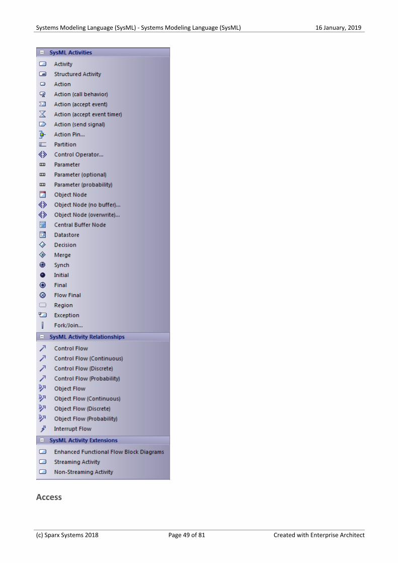
SysML Activity Toolbox
When you are constructing SysML models, you can populate the Activity diagrams using the icons on the 'SysMLActivity' pages of the Diagram Toolbox.
The element that owns the Activity diagram is automatically represented by a diagram frame enclosing the Activitydiagram elements. You can:
Hide the frame by right-clicking on the diagram and selecting the 'Hide Diagram Frame' option (and show it again·by selecting the 'Show Diagram Frame' option)
Make the frame selectable to move or resize it, by right-clicking on it and selecting the 'Selectable' option·
Create structural elements (such as ActivityParameters if the owner is an Activity) on the frame and create·connectors between them and other elements on the diagram
If set to non-selectable, the frame will auto-resize to fit the bounds of the diagram, expanding from its default size but notshrinking smaller.
Note that diagrams showing Diagram Frames applied under release 14.0 or higher of Enterprise Architect will draw theparent object on the diagram when opened in a release prior to release 14.0.
(c) Sparx Systems 2018 Page 48 of 81 Created with Enterprise Architect
Systems Modeling Language (SysML) - Systems Modeling Language (SysML) 16 January, 2019
Access
(c) Sparx Systems 2018 Page 49 of 81 Created with Enterprise Architect
Systems Modeling Language (SysML) - Systems Modeling Language (SysML) 16 January, 2019
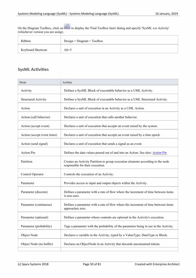
On the Diagram Toolbox, click on to display the 'Find Toolbox Item' dialog and specify 'SysML n.n Activity'(whichever version you are using).
Ribbon Design > Diagram > Toolbox
Keyboard Shortcuts Alt+5
SysML Activities
Item Action
Activity Defines a SysML Block of executable behavior as a UML Activity.
Structured Activity Defines a SysML Block of executable behavior as a UML Structured Activity.
Action Declares a unit of execution in an Activity as a UML Action.
Action (call behavior) Declares a unit of execution that calls another behavior.
Action (accept event) Declares a unit of execution that accepts an event raised by the system.
Action (accept event timer) Declares a unit of execution that accepts an event raised by a time epoch.
Action (send signal) Declares a unit of execution that sends a signal as an event.
Action Pin Defines the data values passed out of and into an Action. See also: Action Pin
Partition Creates an Activity Partition to group execution elements according to the noderesponsible for their execution.
Control Operator Controls the execution of an Activity.
Parameter Provides access to input and output objects within the Activity.
Parameter (discrete) Defines a parameter with a rate of flow where the increment of time between itemsis non-zero.
Parameter (continuous) Defines a parameter with a rate of flow where the increment of time between itemsapproaches zero.
Parameter (optional) Defines a parameter whose contents are optional in the Activity's execution.
Parameter (probability) Tags a parameter with the probability of the parameter being in use in the Activity.
Object Node Declares a variable in the Activity, typed by a ValueType, DataType or Block.
Object Node (no buffer) Declares an ObjectNode in an Activity that discards unconsumed tokens.
(c) Sparx Systems 2018 Page 50 of 81 Created with Enterprise Architect

Systems Modeling Language (SysML) - Systems Modeling Language (SysML) 16 January, 2019
Object Node (overwrite) Declares an ObjectNode in an Activity that overwrites tokens.
Central Buffer Node Declares an ObjectNode that stores tokens for consumption throughout theActivity.
Datastore Defines permanently stored data. See also: Datastore
Decision Creates a branch of control in an Activity, based on a decision.
Merge Merges two or more Activity control branches.
Synch Establishes a rendezvous point for two or more Activity flows, in order tosynchronize their execution in the Activity.
Initial Declares the start of an Activity's execution.
Final Declares the end of an Activity's execution, and the termination of the Activity.
Flow Final Declares the end of an Activity's execution path without terminating the Activity.
Region Groups a subset of an Activity into a common execution context.
Exception Declares a node of execution that happens outside the normal flow of execution ofan Activity.
Fork/Join Simultaneously branches / joins a set of Control or Object Flows.
SysML Activity Relationships
Item Action
Control Flow Establishes a flow of logic between two Activity nodes.
Control Flow (Continuous) Declares a continuous control flow.
Control Flow (Discrete) Declares a discrete control flow.
Control Flow (Probability) Tags a control flow with a probability of the likelihood of the flow's traversal.
Object Flow Establishes a flow of objects (data) between two Activity nodes.
Object Flow (Continuous) Declares a continuous object flow.
Object Flow (Discrete) Declares a discrete object flow.
Object Flow (Probability) Tags an object flow with the probability of the flow's traversal.
Interrupt Flow Declares a control flow that interrupts flow within a Region.
(c) Sparx Systems 2018 Page 51 of 81 Created with Enterprise Architect

Systems Modeling Language (SysML) - Systems Modeling Language (SysML) 16 January, 2019
SysML Activity Extensions
Item Action
Enhanced Functional FlowBlock Diagrams
Action: Declares an Activity used to contain an Enhanced Functional Flow Blockdiagram (EFFBD).
Streaming Activity Declares an Activity where the flow of tokens passes through its parameterscontinuously throughout the Activity's execution.
Non-Streaming Activity Declares an Activity where the flow of tokens passes through its parameters at thestart of the Activity's execution.
(c) Sparx Systems 2018 Page 52 of 81 Created with Enterprise Architect
Systems Modeling Language (SysML) - Systems Modeling Language (SysML) 16 January, 2019
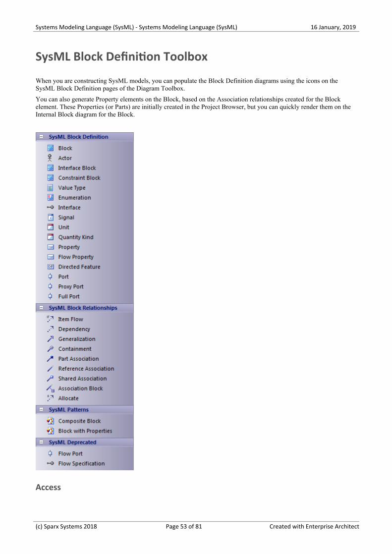
SysML Block Definition Toolbox
When you are constructing SysML models, you can populate the Block Definition diagrams using the icons on theSysML Block Definition pages of the Diagram Toolbox.
You can also generate Property elements on the Block, based on the Association relationships created for the Blockelement. These Properties (or Parts) are initially created in the Project Browser, but you can quickly render them on theInternal Block diagram for the Block.
Access
(c) Sparx Systems 2018 Page 53 of 81 Created with Enterprise Architect
Systems Modeling Language (SysML) - Systems Modeling Language (SysML) 16 January, 2019
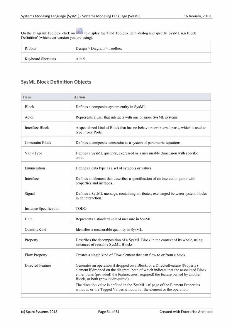
On the Diagram Toolbox, click on to display the 'Find Toolbox Item' dialog and specify 'SysML n.n BlockDefinition' (whichever version you are using).
Ribbon Design > Diagram > Toolbox
Keyboard Shortcuts Alt+5
SysML Block Definition Objects
Item Action
Block Defines a composite system entity in SysML.
Actor Represents a user that interacts with one or more SysML systems.
Interface Block A specialized kind of Block that has no behaviors or internal parts, which is used totype Proxy Ports.
Constraint Block Defines a composite constraint as a system of parametric equations.
ValueType Defines a SysML quantity, expressed as a measurable dimension with specificunits.
Enumeration Defines a data type as a set of symbols or values.
Interface Defines an element that describes a specification of an interaction point withproperties and methods.
Signal Defines a SysML message, containing attributes, exchanged between system blocksin an interaction.
Instance Specification TODO
Unit Represents a standard unit of measure in SysML.
QuantityKind Identifies a measurable quantity in SysML.
Property Describes the decomposition of a SysML Block in the context of its whole, usinginstances of reusable SysML Blocks.
Flow Property Creates a single kind of Flow element that can flow to or from a block.
Directed Feature Generates an operation if dropped on a Block, or a DirectedFeature (Property)element if dropped on the diagram, both of which indicate that the associated Blockeither owns (provided) the feature, uses (required) the feature owned by anotherBlock, or both (providedrequired).
The direction value is defined in the 'SysML1.n' page of the Element Propertieswindow, or the Tagged Values window for the element or the operation.
(c) Sparx Systems 2018 Page 54 of 81 Created with Enterprise Architect
Systems Modeling Language (SysML) - Systems Modeling Language (SysML) 16 January, 2019
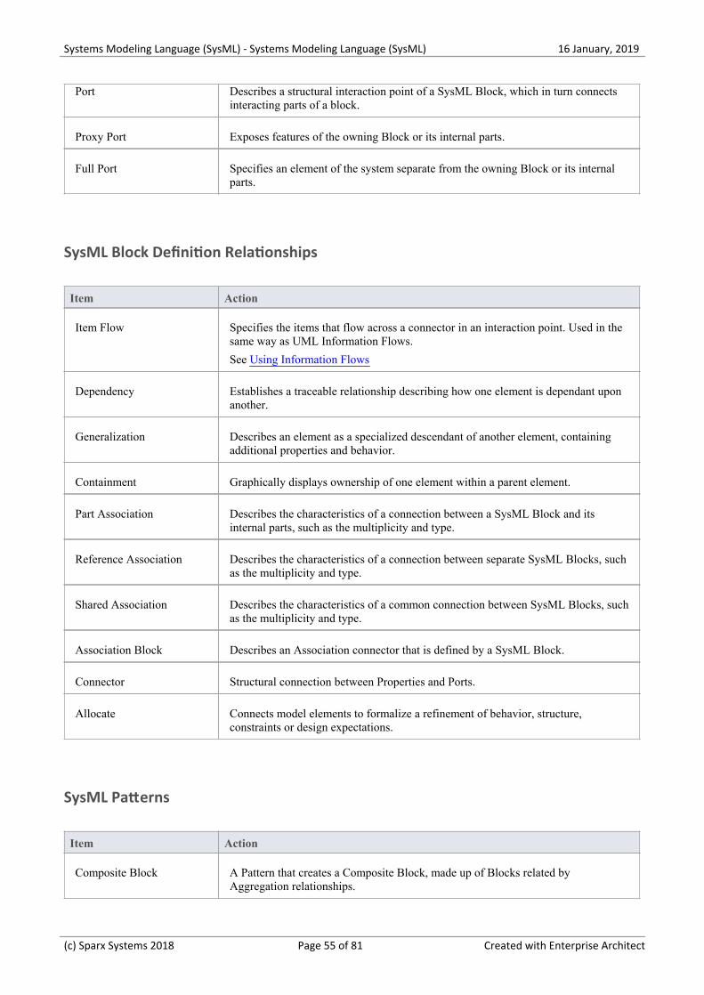
Port Describes a structural interaction point of a SysML Block, which in turn connectsinteracting parts of a block.
Proxy Port Exposes features of the owning Block or its internal parts.
Full Port Specifies an element of the system separate from the owning Block or its internalparts.
SysML Block Definition Relationships
Item Action
Item Flow Specifies the items that flow across a connector in an interaction point. Used in thesame way as UML Information Flows.
See Using Information Flows
Dependency Establishes a traceable relationship describing how one element is dependant uponanother.
Generalization Describes an element as a specialized descendant of another element, containingadditional properties and behavior.
Containment Graphically displays ownership of one element within a parent element.
Part Association Describes the characteristics of a connection between a SysML Block and itsinternal parts, such as the multiplicity and type.
Reference Association Describes the characteristics of a connection between separate SysML Blocks, suchas the multiplicity and type.
Shared Association Describes the characteristics of a common connection between SysML Blocks, suchas the multiplicity and type.
Association Block Describes an Association connector that is defined by a SysML Block.
Connector Structural connection between Properties and Ports.
Allocate Connects model elements to formalize a refinement of behavior, structure,constraints or design expectations.
SysML Patterns
Item Action
Composite Block A Pattern that creates a Composite Block, made up of Blocks related byAggregation relationships.
(c) Sparx Systems 2018 Page 55 of 81 Created with Enterprise Architect
Systems Modeling Language (SysML) - Systems Modeling Language (SysML) 16 January, 2019
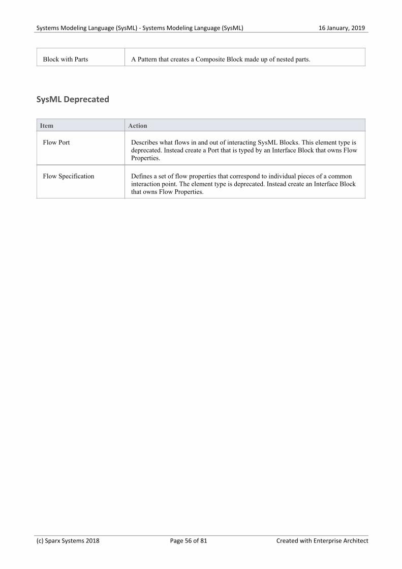
Block with Parts A Pattern that creates a Composite Block made up of nested parts.
SysML Deprecated
Item Action
Flow Port Describes what flows in and out of interacting SysML Blocks. This element type isdeprecated. Instead create a Port that is typed by an Interface Block that owns FlowProperties.
Flow Specification Defines a set of flow properties that correspond to individual pieces of a commoninteraction point. The element type is deprecated. Instead create an Interface Blockthat owns Flow Properties.
(c) Sparx Systems 2018 Page 56 of 81 Created with Enterprise Architect
Systems Modeling Language (SysML) - Systems Modeling Language (SysML) 16 January, 2019
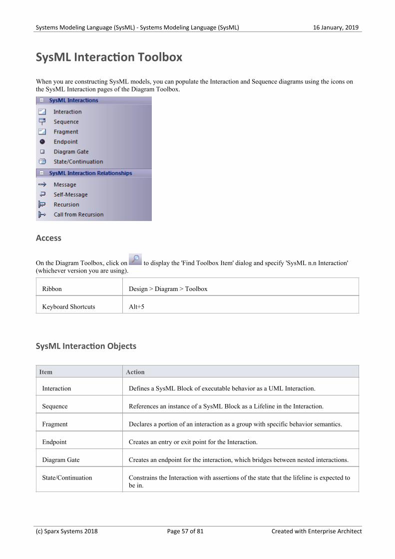
SysML Interaction Toolbox
When you are constructing SysML models, you can populate the Interaction and Sequence diagrams using the icons onthe SysML Interaction pages of the Diagram Toolbox.
Access
On the Diagram Toolbox, click on to display the 'Find Toolbox Item' dialog and specify 'SysML n.n Interaction'(whichever version you are using).
Ribbon Design > Diagram > Toolbox
Keyboard Shortcuts Alt+5
SysML Interaction Objects
Item Action
Interaction Defines a SysML Block of executable behavior as a UML Interaction.
Sequence References an instance of a SysML Block as a Lifeline in the Interaction.
Fragment Declares a portion of an interaction as a group with specific behavior semantics.
Endpoint Creates an entry or exit point for the Interaction.
Diagram Gate Creates an endpoint for the interaction, which bridges between nested interactions.
State/Continuation Constrains the Interaction with assertions of the state that the lifeline is expected tobe in.
(c) Sparx Systems 2018 Page 57 of 81 Created with Enterprise Architect
Systems Modeling Language (SysML) - Systems Modeling Language (SysML) 16 January, 2019
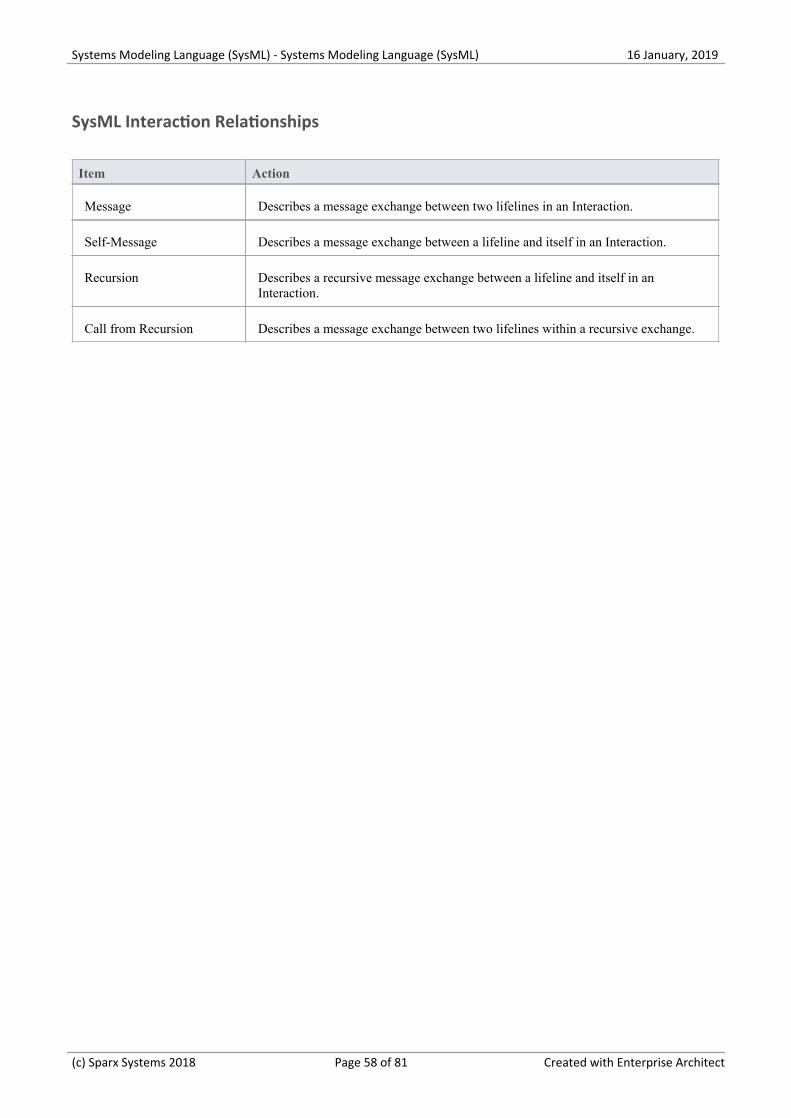
SysML Interaction Relationships
Item Action
Message Describes a message exchange between two lifelines in an Interaction.
Self-Message Describes a message exchange between a lifeline and itself in an Interaction.
Recursion Describes a recursive message exchange between a lifeline and itself in anInteraction.
Call from Recursion Describes a message exchange between two lifelines within a recursive exchange.
(c) Sparx Systems 2018 Page 58 of 81 Created with Enterprise Architect
Systems Modeling Language (SysML) - Systems Modeling Language (SysML) 16 January, 2019
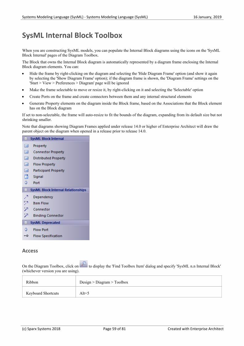
SysML Internal Block Toolbox
When you are constructing SysML models, you can populate the Internal Block diagrams using the icons on the 'SysMLBlock Internal' pages of the Diagram Toolbox.
The Block that owns the Internal Block diagram is automatically represented by a diagram frame enclosing the InternalBlock diagram elements. You can:
Hide the frame by right-clicking on the diagram and selecting the 'Hide Diagram Frame' option (and show it again·by selecting the 'Show Diagram Frame' option); if the diagram frame is shown, the 'Diagram Frame' settings on the'Start > View > Preferences > Diagram' page will be ignored
Make the frame selectable to move or resize it, by right-clicking on it and selecting the 'Selectable' option·
Create Ports on the frame and create connectors between them and any internal structural elements·
Generate Property elements on the diagram inside the Block frame, based on the Associations that the Block element·has on the Block diagram
If set to non-selectable, the frame will auto-resize to fit the bounds of the diagram, expanding from its default size but notshrinking smaller.
Note that diagrams showing Diagram Frames applied under release 14.0 or higher of Enterprise Architect will draw theparent object on the diagram when opened in a release prior to release 14.0.
Access
On the Diagram Toolbox, click on to display the 'Find Toolbox Item' dialog and specify 'SysML n.n Internal Block'(whichever version you are using).
Ribbon Design > Diagram > Toolbox
Keyboard Shortcuts Alt+5
(c) Sparx Systems 2018 Page 59 of 81 Created with Enterprise Architect

Systems Modeling Language (SysML) - Systems Modeling Language (SysML) 16 January, 2019
SysML Block Internal
Item Description
Property Describes the decomposition of a SysML Block in the context of its whole usinginstances of reusable SysML Blocks.
Connector Property Creates an instance of an Association Block.
Distributed Property Creates a stereotype of Property, to apply a probability distribution to the values ofthe property.
Flow Property Creates a single kind of Flow element that can flow to or from a block.
Participant Property Creates the end of a connector owned by an Association Block.
Directed Feature Creates a Feature that might be required, provided or both.
Adjunct Property Creates a Property for which the value is constrained to the value of a connectortyped by an Association Block, Call Action, Object Node, variable, parameter,Interaction Use or SubMachine State.
Bound Reference Creates a Property with the <<BoundReference>> stereotype. Such properties willhave binding connectors to highlight their use as constraining other properties.
End Path Multiplicity Creates a Property with the EndPathMultiplicity stereotype. Such properties will berelated by redefinition to properties that have BoundReference applied.
Classifier BehaviorProperty
Creates a Property with the ClassifierBehaviorProperty stereotype. Such propertieswill constrain their values to be the executions of classifier behaviors.
Signal Defines a SysML message, containing attributes, exchanged between systemBlocks in an interaction.
Port Describes a structural interaction point of a SysML Block which, in turn, connectsbetween interacting parts of a block.
SysML Block Internal Relationships
Item Description
Dependency Establishes a traceable relationship describing how one element is dependant uponanother.
Item Flow Specifies the items that flow across a connector in an interaction point. Used in thesame way as UML Information Flows.
Connector Establishes Communication links between parts.
(c) Sparx Systems 2018 Page 60 of 81 Created with Enterprise Architect
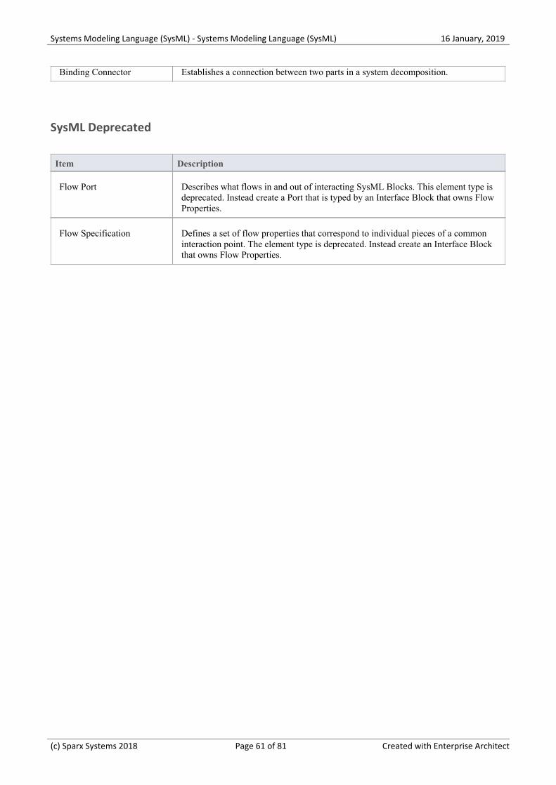
Systems Modeling Language (SysML) - Systems Modeling Language (SysML) 16 January, 2019
Binding Connector Establishes a connection between two parts in a system decomposition.
SysML Deprecated
Item Description
Flow Port Describes what flows in and out of interacting SysML Blocks. This element type isdeprecated. Instead create a Port that is typed by an Interface Block that owns FlowProperties.
Flow Specification Defines a set of flow properties that correspond to individual pieces of a commoninteraction point. The element type is deprecated. Instead create an Interface Blockthat owns Flow Properties.
(c) Sparx Systems 2018 Page 61 of 81 Created with Enterprise Architect
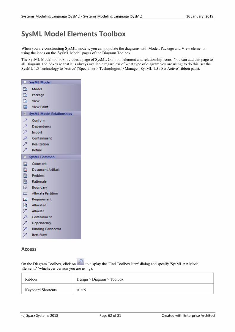
Systems Modeling Language (SysML) - Systems Modeling Language (SysML) 16 January, 2019
SysML Model Elements Toolbox
When you are constructing SysML models, you can populate the diagrams with Model, Package and View elementsusing the icons on the 'SysML Model' pages of the Diagram Toolbox.
The SysML Model toolbox includes a page of SysML Common element and relationship icons. You can add this page toall Diagram Toolboxes so that it is always available regardless of what type of diagram you are using; to do this, set theSysML 1.5 Technology to 'Active' ('Specialize > Technologies > Manage : SysML 1.5 : Set Active' ribbon path).
Access
On the Diagram Toolbox, click on to display the 'Find Toolbox Item' dialog and specify 'SysML n.n ModelElements' (whichever version you are using).
Ribbon Design > Diagram > Toolbox
Keyboard Shortcuts Alt+5
(c) Sparx Systems 2018 Page 62 of 81 Created with Enterprise Architect
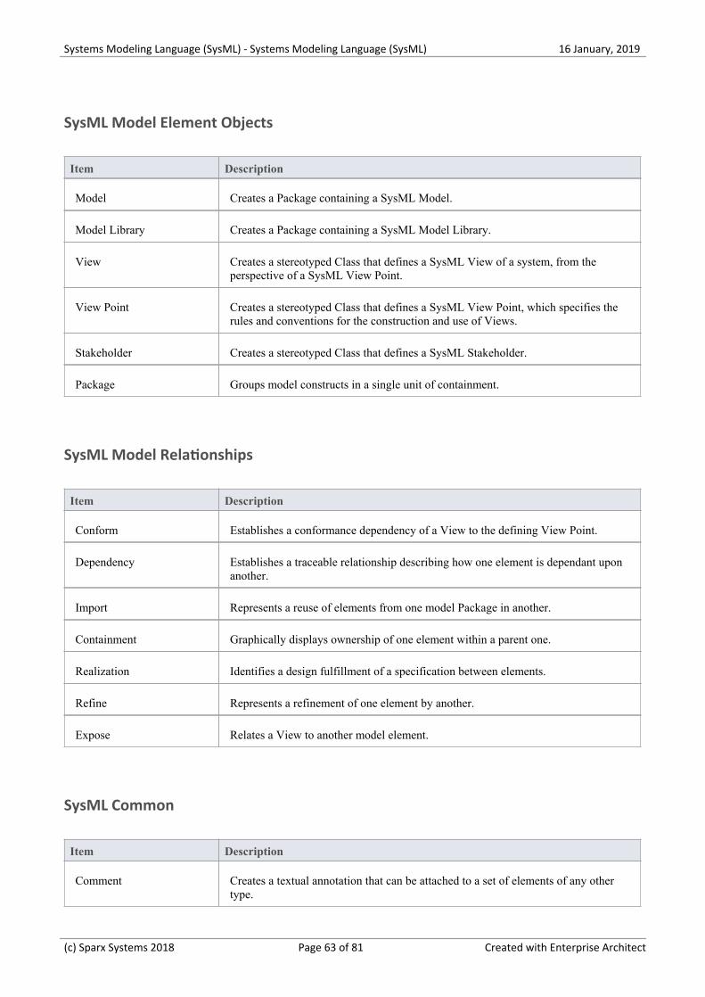
Systems Modeling Language (SysML) - Systems Modeling Language (SysML) 16 January, 2019
SysML Model Element Objects
Item Description
Model Creates a Package containing a SysML Model.
Model Library Creates a Package containing a SysML Model Library.
View Creates a stereotyped Class that defines a SysML View of a system, from theperspective of a SysML View Point.
View Point Creates a stereotyped Class that defines a SysML View Point, which specifies therules and conventions for the construction and use of Views.
Stakeholder Creates a stereotyped Class that defines a SysML Stakeholder.
Package Groups model constructs in a single unit of containment.
SysML Model Relationships
Item Description
Conform Establishes a conformance dependency of a View to the defining View Point.
Dependency Establishes a traceable relationship describing how one element is dependant uponanother.
Import Represents a reuse of elements from one model Package in another.
Containment Graphically displays ownership of one element within a parent one.
Realization Identifies a design fulfillment of a specification between elements.
Refine Represents a refinement of one element by another.
Expose Relates a View to another model element.
SysML Common
Item Description
Comment Creates a textual annotation that can be attached to a set of elements of any othertype.
(c) Sparx Systems 2018 Page 63 of 81 Created with Enterprise Architect
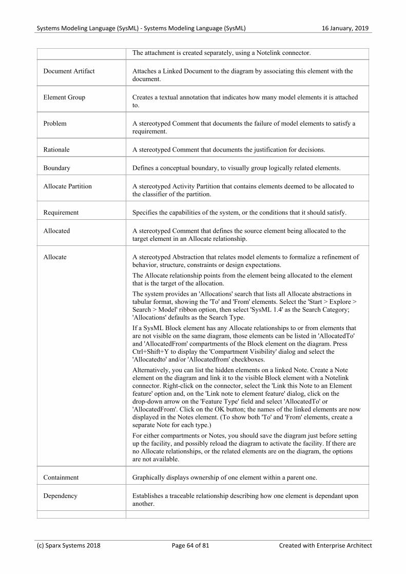
Systems Modeling Language (SysML) - Systems Modeling Language (SysML) 16 January, 2019
The attachment is created separately, using a Notelink connector.
Document Artifact Attaches a Linked Document to the diagram by associating this element with thedocument.
Element Group Creates a textual annotation that indicates how many model elements it is attachedto.
Problem A stereotyped Comment that documents the failure of model elements to satisfy arequirement.
Rationale A stereotyped Comment that documents the justification for decisions.
Boundary Defines a conceptual boundary, to visually group logically related elements.
Allocate Partition A stereotyped Activity Partition that contains elements deemed to be allocated tothe classifier of the partition.
Requirement Specifies the capabilities of the system, or the conditions that it should satisfy.
Allocated A stereotyped Comment that defines the source element being allocated to thetarget element in an Allocate relationship.
Allocate A stereotyped Abstraction that relates model elements to formalize a refinement ofbehavior, structure, constraints or design expectations.
The Allocate relationship points from the element being allocated to the elementthat is the target of the allocation.
The system provides an 'Allocations' search that lists all Allocate abstractions intabular format, showing the 'To' and 'From' elements. Select the 'Start > Explore >Search > Model' ribbon option, then select 'SysML 1.4' as the Search Category;'Allocations' defaults as the Search Type.
If a SysML Block element has any Allocate relationships to or from elements thatare not visible on the same diagram, those elements can be listed in 'AllocatedTo'and 'AllocatedFrom' compartments of the Block element on the diagram. PressCtrl+Shift+Y to display the 'Compartment Visibility' dialog and select the'Allocatedto' and/or 'Allocatedfrom' checkboxes.
Alternatively, you can list the hidden elements on a linked Note. Create a Noteelement on the diagram and link it to the visible Block element with a Notelinkconnector. Right-click on the connector, select the 'Link this Note to an Elementfeature' option and, on the 'Link note to element feature' dialog, click on thedrop-down arrow on the 'Feature Type' field and select 'AllocatedTo' or'AllocatedFrom'. Click on the OK button; the names of the linked elements are nowdisplayed in the Notes element. (To show both 'To' and 'From' elements, create aseparate Note for each type.)
For either compartments or Notes, you should save the diagram just before settingup the facility, and possibly reload the diagram to activate the facility. If there areno Allocate relationships, or the related elements are on the diagram, the optionsare not available.
Containment Graphically displays ownership of one element within a parent one.
Dependency Establishes a traceable relationship describing how one element is dependant uponanother.
(c) Sparx Systems 2018 Page 64 of 81 Created with Enterprise Architect
Systems Modeling Language (SysML) - Systems Modeling Language (SysML) 16 January, 2019
Binding Connector A stereotyped Connector that establishes a connection between two parts in asystem decomposition.
Item Flow A stereotyped Information Flow that specifies the items that flow across aconnector in an interaction point.
(c) Sparx Systems 2018 Page 65 of 81 Created with Enterprise Architect
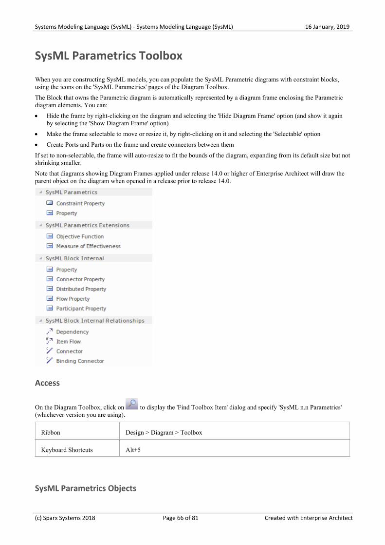
Systems Modeling Language (SysML) - Systems Modeling Language (SysML) 16 January, 2019
SysML Parametrics Toolbox
When you are constructing SysML models, you can populate the SysML Parametric diagrams with constraint blocks,using the icons on the 'SysML Parametrics' pages of the Diagram Toolbox.
The Block that owns the Parametric diagram is automatically represented by a diagram frame enclosing the Parametricdiagram elements. You can:
Hide the frame by right-clicking on the diagram and selecting the 'Hide Diagram Frame' option (and show it again·by selecting the 'Show Diagram Frame' option)
Make the frame selectable to move or resize it, by right-clicking on it and selecting the 'Selectable' option·
Create Ports and Parts on the frame and create connectors between them·
If set to non-selectable, the frame will auto-resize to fit the bounds of the diagram, expanding from its default size but notshrinking smaller.
Note that diagrams showing Diagram Frames applied under release 14.0 or higher of Enterprise Architect will draw theparent object on the diagram when opened in a release prior to release 14.0.
Access
On the Diagram Toolbox, click on to display the 'Find Toolbox Item' dialog and specify 'SysML n.n Parametrics'(whichever version you are using).
Ribbon Design > Diagram > Toolbox
Keyboard Shortcuts Alt+5
SysML Parametrics Objects
(c) Sparx Systems 2018 Page 66 of 81 Created with Enterprise Architect
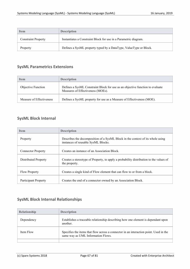
Systems Modeling Language (SysML) - Systems Modeling Language (SysML) 16 January, 2019
Item Description
Constraint Property Instantiates a Constraint Block for use in a Parametric diagram.
Property Defines a SysML property typed by a DataType, ValueType or Block.
SysML Parametrics Extensions
Item Description
Objective Function Defines a SysML Constraint Block for use as an objective function to evaluateMeasures of Effectiveness (MOEs).
Measure of Effectiveness Defines a SysML property for use as a Measure of Effectiveness (MOE).
SysML Block Internal
Item Description
Property Describes the decomposition of a SysML Block in the context of its whole usinginstances of reusable SysML Blocks.
Connector Property Creates an instance of an Association Block.
Distributed Property Creates a stereotype of Property, to apply a probability distribution to the values ofthe property.
Flow Property Creates a single kind of Flow element that can flow to or from a block.
Participant Property Creates the end of a connector owned by an Association Block.
SysML Block Internal Relationships
Relationship Description
Dependency Establishes a traceable relationship describing how one element is dependant uponanother.
Item Flow Specifies the items that flow across a connector in an interaction point. Used in thesame way as UML Information Flows.
(c) Sparx Systems 2018 Page 67 of 81 Created with Enterprise Architect
Systems Modeling Language (SysML) - Systems Modeling Language (SysML) 16 January, 2019
Connector Establishes Communication links between parts.
Binding Connector Establishes a connection between two Parts in a system decomposition.
(c) Sparx Systems 2018 Page 68 of 81 Created with Enterprise Architect
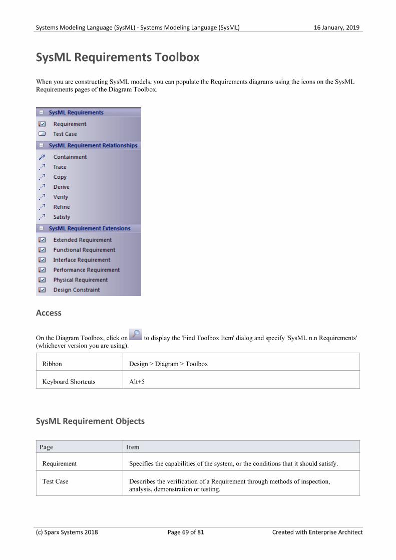
Systems Modeling Language (SysML) - Systems Modeling Language (SysML) 16 January, 2019
SysML Requirements Toolbox
When you are constructing SysML models, you can populate the Requirements diagrams using the icons on the SysMLRequirements pages of the Diagram Toolbox.
Access
On the Diagram Toolbox, click on to display the 'Find Toolbox Item' dialog and specify 'SysML n.n Requirements'(whichever version you are using).
Ribbon Design > Diagram > Toolbox
Keyboard Shortcuts Alt+5
SysML Requirement Objects
Page Item
Requirement Specifies the capabilities of the system, or the conditions that it should satisfy.
Test Case Describes the verification of a Requirement through methods of inspection,analysis, demonstration or testing.
(c) Sparx Systems 2018 Page 69 of 81 Created with Enterprise Architect

Systems Modeling Language (SysML) - Systems Modeling Language (SysML) 16 January, 2019
SysML Requirement Relationships
Item Description
Containment Graphically displays ownership of one element within a parent element.
Trace Declares a trace relationship between a SysML Requirement and another SysMLelement.
Copy Declares a copy of one SysML Requirement by another.
Derive Derives a SysML Requirement from another.
Verify Declares a verification of a SysML Requirement by another SysML element.
Refine Declares a refinement of a SysML Requirement by another SysML element.
Satisfy Declares that the SysML Requirement is satisfied by another SysML element.
SysML Requirement Extensions
Item Description
Extended Requirement Extends a SysML Requirement with additional Tag properties.
Functional Requirement Declares a SysML Requirement that describes the operation, or behavior, that thesystem must perform.
Interface Requirement Declares a SysML Requirement that describes how the system connects, orinterfaces with, other systems.
Performance Requirement Declares a SysML Requirement that describes how the system performs againstdefined capabilities or conditions.
Physical Requirement Declares a SysML Requirement that describes the physical characteristics, orphysical constraints, of the system.
Design Requirement Declares a SysML Requirement that specifies a constraint on the implementation ofthe system.
Notes
SysML Requirements contain the Tagged Values 'Text' and 'ID', the values of which are not immediately visible in·the Tagged Values window; you can see the values more easily if you have the Summary View window open (click
(c) Sparx Systems 2018 Page 70 of 81 Created with Enterprise Architect
Systems Modeling Language (SysML) - Systems Modeling Language (SysML) 16 January, 2019
on the 'Start > Explore > Properties > Summary' ribbon option) when you click on these elements
(c) Sparx Systems 2018 Page 71 of 81 Created with Enterprise Architect

Systems Modeling Language (SysML) - Systems Modeling Language (SysML) 16 January, 2019
SysML StateMachine Toolbox
When you are constructing SysML models, you can populate the StateMachine diagrams using the icons on the 'SysMLStateMachine' pages of the Diagram Toolbox.
The Block that owns the StateMachine diagram is automatically represented by a diagram frame enclosing theStateMachine diagram elements. You can:
Hide the frame by right-clicking on the diagram and selecting the 'Hide Diagram Frame' option (and show it again·by selecting the 'Show Diagram Frame' option)
Make the frame selectable to move or resize it, by right-clicking on it and selecting the 'Selectable' option·
Create Ports and Parts on the frame and create connectors between them·
If set to non-selectable, the frame will auto-resize to fit the bounds of the diagram, expanding from its default size but notshrinking smaller.
Note that diagrams showing Diagram Frames applied under release 14.0 or higher of Enterprise Architect will draw theparent object on the diagram when opened in a release prior to release 14.0.
Access
On the Diagram Toolbox, click on to display the 'Find Toolbox Item' dialog and specify 'SysML n.n StateMachine'(whichever version you are using).
Ribbon Design > Diagram > Toolbox
Keyboard Shortcuts Alt+5
(c) Sparx Systems 2018 Page 72 of 81 Created with Enterprise Architect
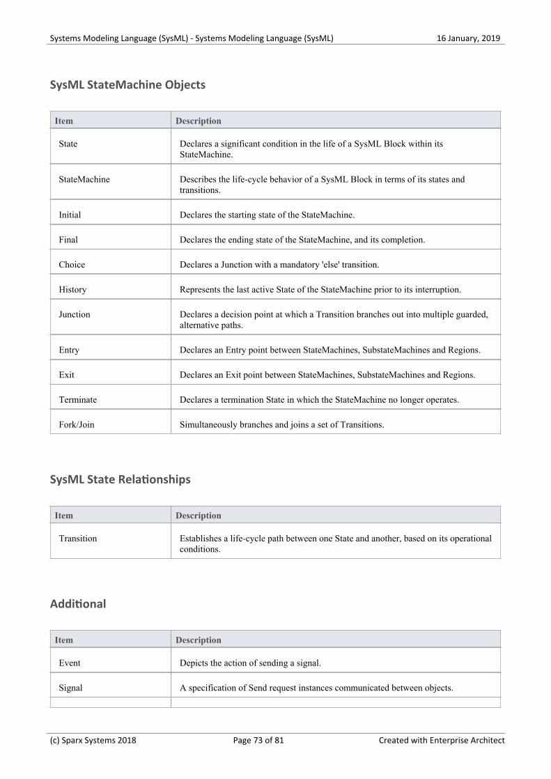
Systems Modeling Language (SysML) - Systems Modeling Language (SysML) 16 January, 2019
SysML StateMachine Objects
Item Description
State Declares a significant condition in the life of a SysML Block within itsStateMachine.
StateMachine Describes the life-cycle behavior of a SysML Block in terms of its states andtransitions.
Initial Declares the starting state of the StateMachine.
Final Declares the ending state of the StateMachine, and its completion.
Choice Declares a Junction with a mandatory 'else' transition.
History Represents the last active State of the StateMachine prior to its interruption.
Junction Declares a decision point at which a Transition branches out into multiple guarded,alternative paths.
Entry Declares an Entry point between StateMachines, SubstateMachines and Regions.
Exit Declares an Exit point between StateMachines, SubstateMachines and Regions.
Terminate Declares a termination State in which the StateMachine no longer operates.
Fork/Join Simultaneously branches and joins a set of Transitions.
SysML State Relationships
Item Description
Transition Establishes a life-cycle path between one State and another, based on its operationalconditions.
Additional
Item Description
Event Depicts the action of sending a signal.
Signal A specification of Send request instances communicated between objects.
(c) Sparx Systems 2018 Page 73 of 81 Created with Enterprise Architect
Systems Modeling Language (SysML) - Systems Modeling Language (SysML) 16 January, 2019
Trigger Indicates an event that initiates an action (and might arise from completion of aprevious action).
(c) Sparx Systems 2018 Page 74 of 81 Created with Enterprise Architect
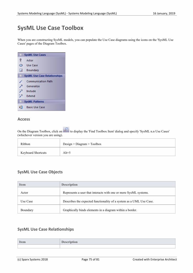
Systems Modeling Language (SysML) - Systems Modeling Language (SysML) 16 January, 2019
SysML Use Case Toolbox
When you are constructing SysML models, you can populate the Use Case diagrams using the icons on the 'SysML UseCases' pages of the Diagram Toolbox.
Access
On the Diagram Toolbox, click on to display the 'Find Toolbox Item' dialog and specify 'SysML n.n Use Cases'(whichever version you are using).
Ribbon Design > Diagram > Toolbox
Keyboard Shortcuts Alt+5
SysML Use Case Objects
Item Description
Actor Represents a user that interacts with one or more SysML systems.
Use Case Describes the expected functionality of a system as a UML Use Case.
Boundary Graphically binds elements in a diagram within a border.
SysML Use Case Relationships
Item Description
(c) Sparx Systems 2018 Page 75 of 81 Created with Enterprise Architect
Systems Modeling Language (SysML) - Systems Modeling Language (SysML) 16 January, 2019
Communication Path Declares which Actors perform in the Use Case.
Generalize Describes an element as a specialized descendant of another element, containingadditional properties and behavior.
Include Describes one Use Case as a subset of another.
Extend Describes one Use Case as an extension of another.
SysML Patterns
Item Description
Basic Use Case A Pattern that creates a typical simple Use Case diagram of Actor, Use Case andSystem Boundary elements.
(c) Sparx Systems 2018 Page 76 of 81 Created with Enterprise Architect
Systems Modeling Language (SysML) - Systems Modeling Language (SysML) 16 January, 2019
Migrate SysML Model to Later SysML Version
Enterprise Architect provides a useful feature to migrate a model from one version of SysML to the next. A model (orpart of a model) created in an older version of the SysML Technology can be migrated to the next version using theAutomation Interface. This function updates the Tagged Values and, if required, stereotypes to the later version for allelements, attributes, connectors and diagrams under the selected Package or element.
There is no facility to migrate a model from SysML 1.4 to SysML 1.5, because the two releases are functionally thesame.
Migrate SysML 1.3 to SysML 1.4
Enterprise Architect's support for SysML 1.4 has a built-in script for migrating 1.3 models to 1.4.
You must enable both the SysML 1.3 Technology and the SysML 1.4 Technology (select the 'Specialize > Technologies> Manage' ribbon option, and select the 'Enable' checkbox for each of the two Technologies).
Select the SysML 1.3 Package in the Project Browser.1.
Open the Scripting window and open the SysML 1.4 script group.2.
Execute the Migrate script.3.
Migrate SysML 1.2 to SysML 1.3
Enterprise Architect's support for SysML 1.3 has a built-in script for migrating 1.2 models to 1.3.
You must enable both the SysML 1.2 Technology and the SysML 1.3 Technology (select the 'Specialize > Technologies> Manage' ribbon option, and select the 'Enable' checkbox for each of the two Technologies).
Select the SysML 1.2 Package in the Project Browser.1.
Open the Scripting window and open the SysML 1.3 script group.2.
Execute the Migrate script.3.
Migrate SysML 1.1 to SysML 1.3
Firstly, follow the steps in Script for Migrating SysML 1.1 to SysML 1.2.
Then follow the steps in Migrate from SysML 1.2 to SysML 1.3.
Script for Migrating SysML 1.1 to SysML 1.2
Run this VB script, which calls the Migrate() function to migrate the SysML 1.1 Package or element to SysML 1.2:
Sub MigrateElement (sGUID, lngPackageID)
Dim proj as EA.Project
set proj = Repository.GetProjectInterface
proj.Migrate sGUID, "SysML1.1", "SysML1.2"
'refresh the model
(c) Sparx Systems 2018 Page 77 of 81 Created with Enterprise Architect
Systems Modeling Language (SysML) - Systems Modeling Language (SysML) 16 January, 2019
If lngPackageID<>0 Then
Repository.RefreshModelView (lngPackageID)
End If
End Sub
Sub MigrateSelectedItem
Dim selType
Dim selElement as EA.Element
Dim selPackage as EA.Package
selType = GetTreeSelectedItemType
If selType = 4 Then 'means Element
set selElement = GetTreeSelectedObject
MigrateElement selElement.ElementGUID, selElement.PackageID
MsgBox "Element Migration Completed",0,"SysML Migration"
ElseIf selType = 5 Then 'means Package
set selPackage = GetTreeSelectedObject
MigrateElement selPackage.PackageGUID, selPackage.PackageID
MsgBox "Package Migration Completed",0,"SysML Migration"
Else
MsgBox "Select a Package or Element in the Project Browser to initiate migration",0,"SysML Migration"
End If
End Sub
Sub Main
MigrateSelectedItem
End SubMain
Notes
When migrating from SysML 1.1 to SysML 1.2, the:· - Stereotype dimension is changed to quantitykind - Stereotype dataType is removed from SysML 1.2 - Tagged Value dimension is migrated to quantitykind; this applies to stereotypes <<unit>> and <<valueType>> - Tagged Value isConjugated in stereotype <<flowport>> is migrated to custom properties
(c) Sparx Systems 2018 Page 78 of 81 Created with Enterprise Architect
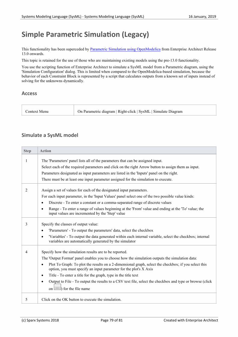
Systems Modeling Language (SysML) - Systems Modeling Language (SysML) 16 January, 2019
Simple Parametric Simulation (Legacy)
This functionality has been superceded by Parametric Simulation using OpenModelica from Enterprise Architect Release13.0 onwards.
This topic is retained for the use of those who are maintaining existing models using the pre-13.0 functionality.
You use the scripting function of Enterprise Architect to simulate a SysML model from a Parametric diagram, using the'Simulation Configuration' dialog. This is limited when compared to the OpenModelica-based simulation, because thebehavior of each Constraint Block is represented by a script that calculates outputs from a known set of inputs instead ofsolving for the unknowns dynamically.
Access
Context Menu On Parametric diagram | Right-click | SysML | Simulate Diagram
Simulate a SysML model
Step Action
1 The 'Parameters' panel lists all of the parameters that can be assigned input.
Select each of the required parameters and click on the right Arrow button to assign them as input.
Parameters designated as input parameters are listed in the 'Inputs' panel on the right.
There must be at least one input parameter assigned for the simulation to execute.
2 Assign a set of values for each of the designated input parameters.
For each input parameter, in the 'Input Values' panel select one of the two possible value kinds:
Discrete - To enter a constant or a comma-separated range of discrete values·
Range - To enter a range of values beginning at the 'From' value and ending at the 'To' value; the·input values are incremented by the 'Step' value
3 Specify the classes of output value:
'Parameters' - To output the parameters' data, select the checkbox·
'Variables' - To output the data generated within each internal variable, select the checkbox; internal·variables are automatically generated by the simulator
4 Specify how the simulation results are to be reported.
The 'Output Format' panel enables you to choose how the simulation outputs the simulation data:
Plot To Graph: To plot the results on a 2-dimensional graph, select the checkbox; if you select this·option, you must specify an input parameter for the plot's X Axis
Title - To enter a title for the graph, type in the title text·
Output to File - To output the results to a CSV text file, select the checkbox and type or browse (click·
on ) for the file name
5 Click on the OK button to execute the simulation.
(c) Sparx Systems 2018 Page 79 of 81 Created with Enterprise Architect
Systems Modeling Language (SysML) - Systems Modeling Language (SysML) 16 January, 2019
Notes
Systems Modeling Language (SysML) Parametric Model Simulation is available in the Unified and Ultimate·editions of Enterprise Architect
(c) Sparx Systems 2018 Page 80 of 81 Created with Enterprise Architect
Systems Modeling Language (SysML) - Systems Modeling Language (SysML) 16 January, 2019
(c) Sparx Systems 2018 Page 81 of 81 Created with Enterprise Architect