systimax 360 1100gs3 and 1100gs6 evolve modular …€¦ · systimax 360™ 1100gs3 and 1100gs6 ......
TRANSCRIPT

860584440 Issue 1, February 2015 www.commscope.com
SYSTIMAX 360™
1100GS3 and 1100GS6 Evolve Modular Panel Instructions
© 2015 CommScope, Inc. All rights reserved
This product is covered by one or more U.S. patents or their foreign equivalents. For patents, see www.commscope.com/ProductPatent/ProductPatent.aspx
Page 1 of 11
For RoHS Inquiries:CommScope Inc.Corke Abbey, BrayCo. Dublin, IrelandAttn: Legal Department
General
The SYSTIMAX 360™ 1100GS3 (Cat 6) and 1100GS6 (Cat 6A) Evolve modular panels exceed ISO and TIA Performance Category standards. The performance category is identified by the color of the jacks. Jacks with gray jack housings are Category 6A (GS6) and jacks with black jack housings are Category 6 (GS3). The SYSTIMAX 360 1100GS3 (Cat 6) and 1100GS6 (Cat 6A) Evolve modular panels and can be used for EIA-T568A or EIA-T568B wiring applications and are available in 24-port and 48-port flat and angled versions.
SYSTIMAX 360 InstaPATCH® fiber modules can be used in the 1100GS 24-port and 48-port flat panels when
the separately orderable Evolve fiber bezels, rear cable management bar, and front cable trough are utilized.
The 1100GS Evolve panels are available iPatch® ready. For instructions on using panels in an iPatch
application, see 860516491 iPatch® Upgrade Module Instructions for SYSTIMAX 360 Panels.
Panel kits are available unpopulated for use with separately ordered modules.
Ordering information for modular panels is listed below:
360 GS3 Modular Panels 360 GS6 Modular Panels
Material ID Description Material ID Description
760152561 1100GS3 Evolve 24-port flat panel 760152587 1100GS6 Evolve 24-port flat panel
760152579 1100GS3 Evolve 48-port flat panel 760152595 1100GS6 Evolve 48-port flat panel
760151308 1100GS3 Evolve 24-port angled panel 760151324 1100GS6 Evolve 24-port angled panel
760151753 1100GS3 Evolve 48-port angled panel 760151779 1100GS6 Evolve 48-port angled panel
Ordering information for panel kits is listed below:
360 Flat Panel Kits* 360 Angled Panel Kits*
Material ID Description Material ID Description
760155739 1100GS Evolve 24-port flat panel kit 760152785 1100GS Evolve 24-port angled panel kit
760155747 1100GS Evolve 48-port flat panel kit 760152793 1100GS Evolve 48-port angled panel kit
*Modules are not included and must be ordered separately
860584440 Instruction Sheet www.commscope.com
Page 2 of 11
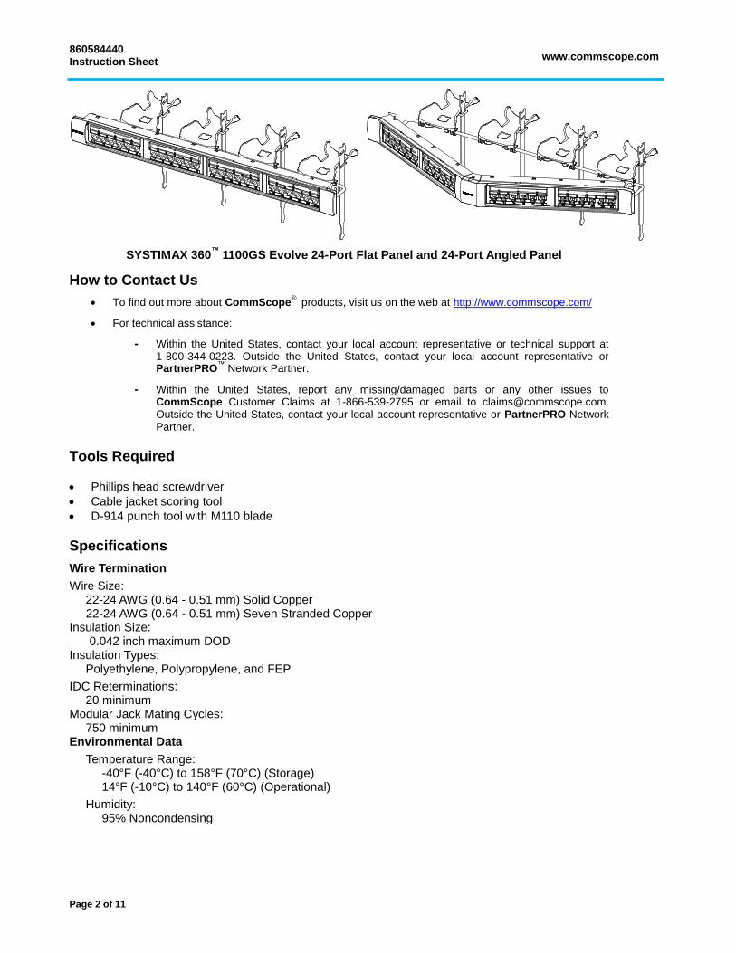
SYSTIMAX 360™
1100GS Evolve 24-Port Flat Panel and 24-Port Angled Panel
How to Contact Us
To find out more about CommScope®
products, visit us on the web at http://www.commscope.com/
For technical assistance:
- Within the United States, contact your local account representative or technical support at 1-800-344-0223. Outside the United States, contact your local account representative or PartnerPRO
™ Network Partner.
- Within the United States, report any missing/damaged parts or any other issues to CommScope Customer Claims at 1-866-539-2795 or email to [email protected]. Outside the United States, contact your local account representative or PartnerPRO Network Partner.
Tools Required
Phillips head screwdriver
Cable jacket scoring tool
D-914 punch tool with M110 blade
Specifications
Wire Termination
Wire Size: 22-24 AWG (0.64 - 0.51 mm) Solid Copper 22-24 AWG (0.64 - 0.51 mm) Seven Stranded Copper
Insulation Size: 0.042 inch maximum DOD Insulation Types:
Polyethylene, Polypropylene, and FEP
IDC Reterminations: 20 minimum
Modular Jack Mating Cycles: 750 minimum
Environmental Data
Temperature Range: -40°F (-40°C) to 158°F (70°C) (Storage) 14°F (-10°C) to 140°F (60°C) (Operational)
Humidity: 95% Noncondensing

www.commscope.com 860584440 Instruction Sheet
Page 3 of 11
Parts List
Verify parts against parts list below:
Quantity
Description 24-Port Flat Panel
48-Port Flat Panel
24-Port Angled Panel
48-Port Angled Panel
1 ─ ─ ─ 24-port flat panel
─ 1 ─ ─ 48-port flat panel
1 24-port angled panel
─ ─ ─ 1 48-port angled panel
1 1 ─ ─ Front cover (1U or 2U)
─ ─ 1 1 Center cover (1U or 2U) angled panel
─ ─ 2 2 Side covers for angled panel (1U or 2U) right and left
4 4 4 4 P12-24 x ½” mounting screws
1 2 1 2 Cable management bar
4 8 4 8 Cable management troughs
4 8 4 8 Hook-and-loop straps
1 2 1 2 Termination manager kit
4 8 4 8 Rear label, T568A wiring
1 2 1 2 Front label card (4 labels per card)
1 2 1 2 Front label cover card (4 covers per card)
1 1 1 1 Instruction sheet
Note: Panel kits include all the parts listed above with the exception of the termination manager kit(s) and T568A
wiring labels. These are provided with the separately ordered distribution modules.
Separately Orderable Items
Contact your SYSTIMAX sales representative for the latest information on the wide variety of 360 InstaPATCH®
modules that are compatible with the fiber bezel.
Distribution modules for the 360 1100GS3/1100GS6 panel kits must be ordered separately and are listed below:
Material ID Description
760151167 360 1100GS3 Evolve distribution module 6-port kit
760151183 360 1100GS6 Evolve distribution module 6-port kit
760175877 360 1100G2 Evolve fiber bezel, 4-pack, cool grey
760175919 360 1100G2 Evolve rear cable manager
760175893 360 1100G2 Evolve 1U front cable trough
760175901 360 1100G2 Evolve 2U front cable trough
WARNING – Important Safety Instructions
When using this product, the following basic safety precautions should be followed to reduce the risk of fire, electric shock, and injury to persons:
1. Never install communications wiring in wet locations unless it is designed for wet locations. 2. Never install this product during a lightning storm. There is a remote risk of electric shock. 3. Never touch uninsulated communication wiring or terminals unless the communication circuit has been
disconnected at the network interface. 4. Caution: All wiring that connects to this equipment must meet applicable local and national building codes
and network wiring standards for communication cable.

860584440 Instruction Sheet www.commscope.com
Page 4 of 11
Step 1 – Mount Panel to Rack
1. Mount panel to rack using the four 12-24 mounting screws provided. After securing panel to rack, snap the Evolve cover(s) onto the front of the panel.
Note: Verify the SYSTIMAX name is upright on the flat panel cover and on angled panel center cover before snapping in place. These two covers can be installed upside down. Side covers on angled panel are interchangeable and are not side specific.
Instructions for Installing Copper Components in Panel (See Page 7 for Installing Fiber Components)
Step 2 – Populate Panel with Distribution Modules (For Panel Kits Only)
Note: Distribution modules are ordered separately.
1. From the rear side of the panel, insert the front face of the module into the desired panel opening. Press firmly until both the left and right side module snaps fully engage with the panel. When installing modules in either of the two end positions, it is necessary to engage the outermost snap first.
Step 3 – Terminate Conductors on Rear of Panel
T568 Wiring Diagram Termination Manager
Note: The module comes with a T568B wiring designation label installed. If T568A wiring is desired, first remove the "B" type label and then place the "A" type label. Do not place the "A" type label on top of the "B" type label.
8 7 6 5
2 1 4 3
4 4
3
2
1
2
3
1
B A
1 2 3 4 5 6 7 8 BR BR
GR
GROR
OR
BL BL
W
W W
W
T568 Wiring Pairs
IDC ConnectorModular Jack
Front of Panel Back of Panel
Lock tab(2 places)
Entryholes
Fold slots(4 places)
Entry holes

www.commscope.com 860584440 Instruction Sheet
Page 5 of 11
Note: If using SYSTIMAX GigaSPEED® X10D 91B series cable, 95B series cordage, or Xpress
® 88 series
cable, see preparation instructions below.
Note: See pages 10 and 11 for proper use of the termination manager.
1. Prepare cable for IDC termination. Terminate conductors on the IDC terminals per the wiring diagram shown above and utilizing the termination manager.
Preparation of X10D 91B Series Cable, 95B Series Cordage, or Xpress 88 Cable for Termination
Preparation of the SYSTIMAX GigaSPEED X10D 91B series cable, 95B series cordage, or Xpress 88 series cable is shown above. For complete instructions on preparing these cables for termination, see instruction sheet 860469402.
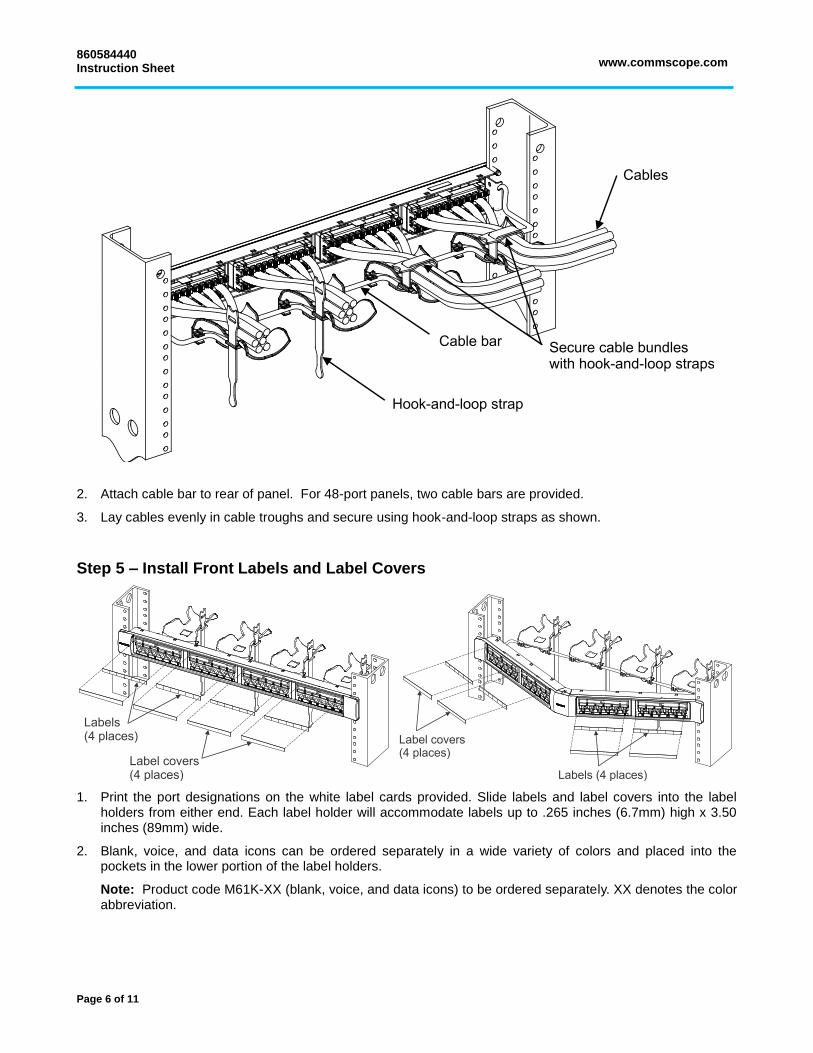
Step 4 – Assemble and Install Rear Cable Manager
1. Attach the four cable troughs onto bar as shown and insert four hook-and-loop straps into slots in cable troughs.
Pull flute and tapes
off to one or more sides
Unwind separator tape Pull off to the side so that it can
be trimmed close to the jacket
860584440 Instruction Sheet www.commscope.com
Page 6 of 11
2. Attach cable bar to rear of panel. For 48-port panels, two cable bars are provided.
3. Lay cables evenly in cable troughs and secure using hook-and-loop straps as shown.
Step 5 – Install Front Labels and Label Covers
1. Print the port designations on the white label cards provided. Slide labels and label covers into the label holders from either end. Each label holder will accommodate labels up to .265 inches (6.7mm) high x 3.50 inches (89mm) wide.
2. Blank, voice, and data icons can be ordered separately in a wide variety of colors and placed into the pockets in the lower portion of the label holders.
Note: Product code M61K-XX (blank, voice, and data icons) to be ordered separately. XX denotes the color abbreviation.

www.commscope.com 860584440 Instruction Sheet
Page 7 of 11
3. To print a designation label, go to http://www.commscope.com/Resources/Labeling-Templates and scroll
down to 360 Panels and Shelves. Select the proper label template:
360 Evolve-360 PATCHMAX UNP Label Sheet A4 (760186502)
or
360 Evolve 360 PATCHMAX UNP Label Sheet US LTR (760183244).
Note: Labeling website has two options for printing labels; letter size and A4 size.
Instructions for Installing Fiber Components in Panel
Step 2a – Install Evolve Fiber Adapter Bezels
Note: Fiber modules, bezels, rear trunk cable management bar, and front fiber management trough are ordered separately.
1. Position a bezel against opening from rear of panel. Push bezel from the rear until it snaps into panel opening. Repeat for all bezels.
Step 3a – Install Evolve G2 Fiber Trunk Cable Management Bar on Rear of Panel
1. Attach fiber management bar to rear of panel immediately behind the fiber row. Place hook at both ends of bar into slots in panel brackets as shown.
Step 4a – Install Evolve G2 Fiber Management Trough on Front of Panel
Note: For instructions on installing the fiber management trough, see 860548809 SYSTIMAX 360 1100 Evolve G2 Fiber Management Trough.
1. Refer to the instructions packaged with the trough and install either the 1U trough on front of the 24-port panel or the 2U trough on front of the 48-port panel.
2. Refer to the instructions packaged with the trough and install designation labels on trough door.

860584440 Instruction Sheet www.commscope.com
Page 8 of 11
Step 5a – Populate Panel with Fiber Modules
1. Orient module in ALPHA or BETA position as required and insert into one of the openings in the panel.
2. Push module into opening until latches engage with an audible click.
3. Repeat for remaining modules.
Step 6a – Install and Route Fiber Trunk Cables
1. Terminate MPO connectors into modules.
2. Slip fiber routing clips over fiber management bar at equally spaced positions, similar to as shown above.
3. Spread open a slot position provided on fiber routing clip and secure fiber cable inside.
4. Repeat until all cables are inserted in the clips and adjust position of clips as necessary to hold the trunk cables in an organized manner.
5. Wrap a strip of hook-and-loop fastener around each fiber routing clip to secure cables.
Fibermanagementsystem
Fiber routing clips
Fiber trunk cables(not supplied)
Fiber module(not supplied)
Hook and loop strip
MPO connector

www.commscope.com 860584440 Instruction Sheet
Page 9 of 11
(Optional Step) Removing Covers from Panel
1. When removing either the flat or angled panel side cover(s), grip cover on the top and bottom at the outside edge where shown by arrows and pull forward. As cover tabs release, position fingers close to tabs to apply further pulling force.
2. For angled panel only, remove both side covers from panel before removing center cover.

860584440 Instruction Sheet www.commscope.com
Page 10 of 11
1 Patch Panel Termination Manager Instructions
The termination managers provide pair positioning, control, and strain relief features to the rear termination area of the panel. See Figure 1. Instructions for using the termination manager are listed below.
Feed Pairs into Termination Manager (Figure 2)
1. Trim jacket back at least 3 inches (76mm) to expose twisted pairs.
2. Without crossing over or rearranging pairs out of the jacket, position pairs in-line per pair colors below:
T568B Wiring Application (Shown) Blue, Brown, Orange, Green
T568A Wiring Application Blue, Brown, Green, Orange
3. Insert pairs through 4 holes on top surface of termination manager, one pair per hole, as shown.
4. Continue to feed pairs through termination manager until resistance is encountered at the jacket. This will usually be about 1/4 inch (6mm) from the jacket.
Fold Pairs into Slots (Figure 3)
5. Fold each pair over into adjoining slots on bottom end of termination manager. Conductor colors must be arranged in the slots as listed below:
T568B Wiring Application (Shown)
BL/OR Pairs – Blue/Orange conductors on top BR/GR Pairs – both White conductors on top
T568A Wiring Application
BL/GR Pairs – Blue/Green conductors on top BR/OR Pairs – both White conductors on top
Important: Add twist as needed to align pairs with slots. Never remove twist for any pair. Do not allow pairs to untwist inside termination manager or inside cable jacket.
6. Ensure that both conductors of each pair are in slots completely without being pinched over bottom end surface.
Figure 1. Termination Manager
Lock tab(2 places)
Entryholes
Fold slots(4 places)
Entry holes
Figure 2. Feed Pairs into Termination Manager
Topsurface
Orange pairBrown pair
Blue pair Green pair
Figure 3. Fold Pairs Back into Slots
Orange on top
White ontop
Blue on top

www.commscope.com 860584440 Instruction Sheet
Page 11 of 11
Snap Termination Manager onto Rear Housing (Figure 4)
7. Snap assembled termination manager onto rear housing with pair colors in proper position. Push on using the termination manager housing, not by pushing with the cable. (Ensure that both lock tabs on manager fully seat into rear housing).
8. After termination manager is snapped onto rear housing, untwist individual pairs fully and line up correct color conductor and white conductor with the label on the rear housing.
Seat Wires into IDC Terminal Slots (Figure 5)
9. Grasping each untwisted pair, push the conductors down into IDC terminal slots to seat them before punching down. Seat down into slots as far as possible. (It may be easier to use needle nose pliers to perform this task).
10. Using the D-914 punch tool with M110 blade on HI impact setting, punch down conductors making sure the tool is straight and that conductors fully engage in the IDC terminals. Stagger the punch-down tool up and down, so that it stays in alignment with the staggered terminal slots.
Recommendations to Aid Assembly
1. The termination manager should be snapped onto the rear housing immediately after the pairs have been fed and folded over into the slots. All termination managers should be installed on the panel before proceeding to seat and punch down conductors.
2. Flex cables down for easier access, then seat and punch down the entire top row of the panel.
3. Flex cables up for easier access, then seat and punch down the entire bottom row.
2
Figure 4. Snap Termination Manager onto Rear Housing
Pairsfolded back
Figure 5. Seat Untwisted Pairs into IDC Terminal Slots
Visiblepair entry
Remove twists,then pushconductorsdown intoterminal slots