systimax solutions instapatch cu cabling solutions for ... · pdf fileinstapatch® cu...
TRANSCRIPT

www.commscope.com
SYSTIMAX® Solutions
InstaPATCH® Cu Cabling Solutions for Data Centers Design GuidelinesAugust 2008

www.commscope.com
Overview 1
InstaPATCH Cu Solution Specification 2
Harness Assembly Design 3
Data Center Copper Cabling Channel Models 7
Mixed Cabling Configurations 10
Design Example 11
Contents

www.commscope.com 1
Overview
Through its InstaPATCH® Cu Pre-Terminated Copper Solutions, CommScope now provides pre-connectorized copper cable harnesses for Data Center networking and infrastructure needs. InstaPATCH Cu Solutions are designed to support locations, such as Data Centers, that require high density, rapid deployment and high performance.
Features and benefits of InstaPATCH Cu solutions:
• Pre-Terminated GigaSPEED® XL Solution is guaranteed to meet or exceed Category 6/ Class E Channel Specs to 250 MHz
• Pre-Terminated GigaSPEED® X10D Solution is guaranteed to meet or exceed Category 6A/Class EA Channel Specs to 500 MHz
• Installation up to eight times faster than traditional cabling. No cable punch-downs
• Factory tested and test report available upon request
• Unique, customizable labeling identification
• Multiple options for a variety of copper environments
• 20-year Extended Product and Application Warranty
• Technician exposure greatly reduced in live data centers
• SwitchPack technology supplies high-density switches with a UTP pre-built, quick connect/disconnect feature, allowing superior cable management and extending the switch to patch panels where cross-connects can be made. SwitchPack Technology brings greater reliability and serviceability to your network
• All three materials are available: PVC, plenum and LSZH

www.commscope.com 2
InstaPATCH Cu Solution SpecificationsSYSTIMAX InstaPATCH Cu solutions are factory-processed CommScope GigaSPEED cabling systems. The factory processes include termination, bundling, testing, labeling and packaging. The corresponding specifications of CommScope field-terminated copper solutions apply to their pre-terminated counterparts as shown in Table 2.1.
TABLE 2.1 INSTAPATCH CU SOLUTION SPECIFICATIONS
InstaPATCH Cu solutions Channel performance Applications Design Rule Highlights
Pre-term GigaSPEED X10D Meet or exceed ISO/IEC11801:2002 Class EA
10 Gigabit Ethernet up to 100 meters
Minimum 15 meter long horizontal cable
Pre-term GigaSPEED XL Meet or exceed TIACategory 6 / ISO/IECClass E
1 Gigabit Ethernetup to 100 meters
Refer to the following design guidelines of CommScope field-terminated copper cabling solutions:
• SYSTIMAX GigaSPEED X10D Solution Design and Installation Guideline for UTP
• SYSTIMAX GigaSPEED XL Solution Design and Installation Guidelines

www.commscope.com 3
Harness Assembly Design
Table 3.1 lists the applications of SYSTIMAX InstaPATCH Cu solutions.
TABLE 3.1 INSTAPATCH CU SOLUTION APPLICATIONS
Harness Name Applications
Server Cabinet Harness Servers to in-cabinet distributed switches
Backbone Harness • Patch Panel to Patch Panel between floors or Telecommunication Closets
• Block to Block between floors or riser extension
Switch Harness • High-Density Chassis Switches
• 6, 8, 12, 16 and 24-port increments
• SwitchPack connectivity
Horizontal Harness Patch Panel to Patch Panel
Bundling Cables or cords are randomly bundled in a harness. Table 3.2 provides the options and recommendations for harness bundling.
TABLE 3.2 HARNESS BUNDLING OPTIONS AND RECOMMENDATIONS
Options Recommendation
Cable bundle size 4, 6, 8, 12, 16, 24 12
Equipment cord bundle size 4, 6, 8, 12, 16, 24 12
Bundling material Expando, Hook and loop fastener, cable ties
Expando
Harness A basic element of InstaPATCH Cu solution is the harness. Figure 3.1 shows four SwitchPack harnesses at left. Each harness is bundled in Expando and has 12 legs. The plug ends of the four harnesses have 6x2 port SwitchPacks. Figure 3.1 also gives out a larger image of a Dual Row 12 port SwitchPack in 6x2 format.
Figure 3.1 Four SwitchPack harnesses and a 6x2 SwitchPack

www.commscope.com 4
SwitchPack
SwitchPack technology supplies high-density switches with a UTP pre-built, quick connect/disconnect feature. SwitchPacks allow superior cord management. It also extends the switch to patch panels where cross-connects can be made. SwitchPack Technology brings greater reliability and serviceability to your network. Table 3.3 lists SwitchPack options and recommendations.
You must consider the front networking interface panel of a “to-be-used switch” before selecting a SwitchPack. The most common high-density switches for Data Centers are equipped with modules of 48 RJ45 ports per module. Figure 3.2 provides images of a Cisco WS-X6548-GE-TX module at left and a Foundry Networks® FastIron® SX 1600 at right.
Figure 3.2 A high density switch module or chassis
Exit OrientationA harness assembly can have multiple exit options (Left, Left (Paired), Right, Right (Paired), Trident and Straight) on either horizontal or vertical level configurations. Figure 3.3 shows right exit staggers of four switch harnesses. The right exit design is appropriate in this case because the Catalyst 6500 series switch has a vertical fan module at the left side as indicted by the red arrow. If the harnesses would exit to the left, all of the cords would be necessary to be unplugged before replacing a failed fan module. The blue arrow points to the position of the harness breakouts at the end of the Expando sleeving.
TABLE 3.3 SWITCHPACK OPTIONS
Option Array Format (legs per row x rows)
Dual Row 16 8x2
Dual Row 12 6x2
Dual Row 8 4x2
Single Row 8 8x1
Single Row 6 6x1
Single Row 4 4x1

www.commscope.com 5
Figure 3.3 An example of four SwitchPack harnesses with right (paired) exit orientation
Figure 3.4 shows a depiction of various exit orientations. What the red arrows point out can be either a patch panel or a switch’s front panel, and the blue arrows indicate the breakout of cables or cords.
Figure 3.4 Exit orientation options
Straight
Right
Paired
Left
Trident
www.commscope.com 6
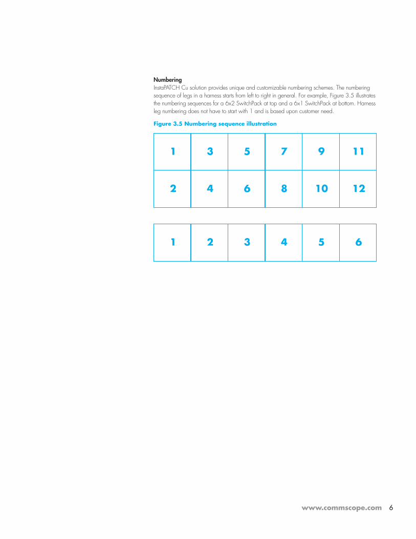
NumberingInstaPATCH Cu solution provides unique and customizable numbering schemes. The numbering sequence of legs in a harness starts from left to right in general. For example, Figure 3.5 illustrates the numbering sequences for a 6x2 SwitchPack at top and a 6x1 SwitchPack at bottom. Harness leg numbering does not have to start with 1 and is based upon customer need.
Figure 3.5 Numbering sequence illustration
1 5 93 7 11
2 6 104 8 12
1 3 52 4 6

www.commscope.com 7
Data Center Copper Cabling Channel Models The following illustrations identify various channels between different areas within a data center. These standards-defined configurations contain up to four connections. A connection is where two cabling segments come together, while the connections on the end equipment are not counted in the models.
Two Connection ModelThe most basic channel model has only two connections and is typically referred to and tested (without the cords) as a permanent link. The horizontal with the cords may also be tested as a channel.
Figure 4.1 Two Connection Model, Interconnection to Interconnection

www.commscope.com 8
Three Connection ModelsA third connection can support two different channel models, a cross-connection or a consolidation point.
At large sites or sites with a high density of switching equipment or where space constraints might otherwise dictate, the horizontal distribution area can be configured with a cross-connection. This configuration is typically referred to and tested (with the cords) as a channel. This configuration can also be applied to backbone cabling with a main cross-connect.
Figure 4.2 Three Connection Model, Cross-connection to Interconnection
Where a site administrator may require flexibility or where an installation may be staged, the horizontal cable can be terminated at a consolation point. It might be used, for example, to terminate a horizontal bundle at the middle of a row of equipment, and allow the site administrator to apportion horizontal cables between sections of the row as needed. This configuration is typically called a Permanent Link. It may be tested without the cords as a permanent link, or with the cords as a channel.

www.commscope.com 9
Figure 4.3 Three Connection Model, Interconnection with a Consolidation Point
Four Connection ModelsAt large data centers the cabling administration is typically consolidated at cross-connects, and four connections would be used in channels. These configurations are typically referred to and tested (with the cords) as a channel. There are two configurations, a cross-connection with a consolidation point and a double cross-connect.
The consolidation point configuration in Figure 4.4 allows for two levels of administration to the server equipment as in Figure 4.3, but also provides a cross-connect for the switching equipment. The consolidation point may be useful for flexibility allocating horizontal capacity to many small customers that must be independently maintained.
Figure 4.4 Four Connection Model, Cross-Connection to Consolidation Point
www.commscope.com 10
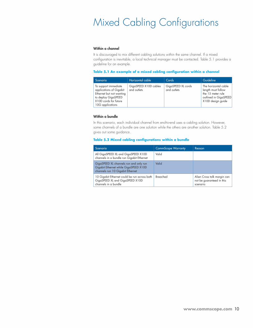
Mixed Cabling Configurations
Within a channel
It is discouraged to mix different cabling solutions within the same channel. If a mixed configuration is inevitable, a local technical manager must be contacted. Table 5.1 provides a guideline for an example.
Table 5.1 An example of a mixed cabling configuration within a channel
Scenario Horizontal cable Cords Guideline
To support immediate applications of Gigabit Ethernet but not wanting to deploy GigaSPEED X10D cords for future 10G applications
GigaSPEED X10D cablesand outlets
GigaSPEED XL cords and outlets
The horizontal cable length must follow the 15 meter rule outlined in GigaSPEED X10D design guide
Within a bundle
In this scenario, each individual channel from end-to-end uses a cabling solution. However, some channels of a bundle are one solution while the others are another solution. Table 5.2 gives out some guidance.
Table 5.2 Mixed cabling configurations within a bundle
Scenario CommScope Warranty Reason
All GigaSPEED XL and GigaSPEED X10D channels in a bundle run Gigabit Ethernet
Valid
GigaSPEED XL channels run and only run Gigabit Ethernet while GigaSPEED X10D channels run 10 Gigabit Ethernet
Valid
10 Gigabit Ethernet could be run across both GigaSPEED XL and GigaSPEED X10D channels in a bundle
Breached Alien Cross talk margin can not be guaranteed in this scenario

www.commscope.com 11
Design Example
Figure 6.1 represents the layout of a scaled-down Data Center. The model consists of four server rows and one network row. Each server row consists of 10 cabinets. The network row has five racks. The cabinets or racks are standard 19” equipment mounting rail size and 42U height housing systems. CommScope provides both server and network cabinet solutions and cable management as well.
Figure 6.1 A scaled down Data Center layout
The model uses a hot-aisle and cold-aisle design. It utilizes a raised floor to deliver cooling air. Two pairs of Computer Room Air-conditioning (CRAC) units are aligned to the hot aisles.
The computing capacity of each server cabinet in the Data Center model is:
• Each server cabinet houses twelve 2U rack-mount servers
• Each server has two LAN interfaces on motherboard (LOMs) named LOM0 (primary) and LOM1(secondary). The logical network connections of each server is illustrated in Figure 6.2
Therefore, the design of the model in Figure 6.1 requires 40 server cabinets, 480 2U servers, and 960 copper channel drops.
Figure 6.2 The primary and secondary networking connections for each server

www.commscope.com 12
The Data Center model applies the Three Connection Model illustrated in Figure 4.3 in Section 4. There are forty 1U 24-port patch panels to be mounted in the cross-connect racks. SYSTIMAX’s 1100GS5 or M2000 with MGS500 outlets provide 24-port outlets in a 1U patch panel. If installing twenty 1U patch panels per rack, four 42U racks are needed for cross-connects. The remaining 22 U space in the network racks are used by cable management fixtures. Racks E02, E03, E04 and E05 are used to house the 40 cross-connect patch panels. CommScope provides network cabinets and cable management fixtures meeting the design requirements.
The 960 copper cabling drops require ten 48-port Ethernet modules as shown in Figure 3.2. Two identical high-density switches can implement this design.
A server cabinet and a network rack are highlighted in red and blue respectively as shown in Figure 6.1. An orange line connects the red server cabinet (labeled as Cab B11) to the blue network rack (labeled as Rack E03). This orange line represents a route of the horizontal cables deployed overhead. Assume that the length of the orange line is 82 feet or 25 meters.
The rest of the section will use Cab B11 and Rack E03 along with the orange route as an example to illustrate pre-terminated harness design.
Figure 6.3 shows the front view of Cab B11 and the three network racks named E01, E02 and E03. Cab B11 and the 3 racks juxtaposed in the figure are for illustration purposes. Figure 6.3 does not reflect real physical locations or dimensions.
According to the computing capacity requirement, Cab B11 should house twelve 2U rack-mount servers. Only one server (Server B11-01) is illustrated in Figure 6.3. Rack E02 and E03 contain patch panels for cross-connect patching. Rack E01 houses two high-density switches E01-1 and E01-2.
Switches E01-1 and E01-2 compose a redundant group. If space is available, it would be a good idea to mount the two switches in separate racks. Physical separation increases networking availability by reducing the common failure points.
Table 6.1 lists the pre-terminated harnesses to meet the cabling design from servers in Cab B11 to switch ports in Rack E03/E02/E01. The example selects SYSTIMAX GigaSPEED X10D solutions.
Figure 6.3 The front view of Cab B11 and network racks
Server Cab B 11 Network
Rack E 03
Network
Rack E 02Network
Rack E 01
Server B 11-01
Raised floor
Server
Equipment
cord to
LOM 0
Cable drop
in Rack E 03
1 switch
harness with
12 legs
Cable drop
in Cab B11
42 U Cab Height
6 ' 5 /8 "
2 horizontal harnesses
with 12 legs
Server
Equipment
cord to
LOM 1
Switch E01-2
( secondary )
Switch E01-1
( primary )
1 switch
harness with
12 legs
Overhead cable tray height
8'
48 Cross -
connect
cords
Patch Panel Height
4 '

www.commscope.com 13
Table 6.1 Harness Design for the channels from Cab B11 to Rack E03 and between Rack E02 and Rack E01
Harness name Horizontal harnessB11-E03
Switch HarnessE02-E01
Performance GigaSPEED X10D GigaSPEED X10D
Leg count 12 12
Environment PVC PVC
Bundling Expando Expando
Connector - switch side
Outlet- in Rack E03
Dual row SwitchPack 12- in Rack E01
Exit Orientation- switch side
Left1- in Rack E03
Right- in Rack E01
Leg numbering- switch side
01- in Rack E03
01- in Rack E01
Connector- server side
Outlet- in Cab B11
Outlet- in Rack E02
Exit Orientation- server side
Left- in Cab B11
Right1- in Rack E02
Leg numbering- server side
01- in Cab B11
01- in Rack E02
Pulling Eye None None
Length 94 feet 2
Note: GigaSPEED X10D design Guide requires 15 meter or longer horizontal cables
Minimum 10 feet
Note: GigaSPEED X10D Design Guide requires 3 meter or longer equipment cord
Quantity of harness 4 – recommendedOr2 – only fulfills immediate need
4 – recommendedOr2 – only fulfills immediate need
Note 1: The Exit Orientation of different harnesses should alternate in order to avoid cable jams.
Note 2: Assuming the patch panels in Cab B11 are installed at the top and face the rear, the calculation of the horizontal harness length is:
Horizontal harness length = Orange line length + [overhead tray height – server patch panel height (cabinet height here)] + [overhead tray height – cross-connect patch panel height] + cable slack estimate = 82 + 8 – 6 5/8 + 3+ 6 = 94 feet.

www.commscope.comVisit our Web site or contact your local CommScope representative for more information. © 2017 CommScope, Inc. All rights reserved.
All trademarks identified by ® or ™ are registered trademarks or trademarks, respectively, of CommScope, Inc.
This document is for planning purposes only and is not intended to modify or supplement any specifications or warranties relating to CommScope products or services.
MI-B-7 02/17