t-berd 950 communications analyzer - mhz … acterna t-berd 950 communications analyzer is a multi...
TRANSCRIPT

T-BERD® 950Communications Analyzer
The Acterna T-BERD 950 Communications Analyzer is a multi-functional instrument thatcombines troubleshooting and turn-up testing capabilities for digital, analog, voice, and datacircuits in one unit. The T-BERD 950 thoroughly tests digital services such as T1/FT1, DDS localloop, and T1 PBX trunks. It also supports testing for analog services such as DID and analog data.Protocol services including ISDN BRI, ISDN PRI, and frame relay, in addition to other networktechnologies and services are also supported by the T-BERD 950. Built with the demands of thefield technician in mind, the T-BERD 950 is designed to expand and support new technologies andservices without sacrificing ease of use or portability.
Product Highlights• Multiple service testing capabilities
combined in a single test instrament• Analog and digital testing support• Growth-oriented protocol service
board and interface module expansionslot for future test access capability
• TNT Task Based Testing user interface makes routine test set-up simpleand intuitive
• Large graphical LCD allows for twouser display screens and a two-line results display
• Use AC or battery power with dual hot-swappable, field replaceablebatteries
Application Highlights• Qualify local loop copper wire pairs
for both analog and digital services• Perform full-duplex monitoring of
active T1 and DDS lines• Verify and troubleshoot ISDN BRI
and PRI services• Test the ability to handle incoming
calls with PBX/Switch emulation• Install and maintain frame relay
service from T1, DDS, and Datacominterface
• Perform IP service verification and trouble isolation from a 10BaseT interface

Functions• Perform standard T1 BER testing and signal analysis measurements• Gain T1/FT1 access for BER testing with standard and advanced stress patterns, as well as built-in T1 smart
repeater and HDSL loopcodes• Test end-to-end WAN service through DTE/DCE equipment emulation and in-service monitoring• Perform TIMS measurements for qualification of voice and data circuits; place, receive calls, and perform
signaling event/digit analysis on analog loop start, ground start, and DID voice circuits• Verify circuit-switched ISDN BRI voice, data, and D packet services by performing NT1 and LT BERT, or
NT1/TE emulation
The T-BERD 950 can verify network/WAN connectivity from an Ethernet interface by transmitting Internet con-trol message protocol (ICMP) echo requests (PINGs) and respond to received PINGs. Additionally, the T-BERD950 can place, receive, and monitor ISDN PRI calls on 23 B+D, 47 B+D, and 46 B+2D circuits while viewing fulllayer 3 D channel decodes. When testing DS0 channels, the T-BERD 950 can place, receive, or monitor calls as wellas analyze captured signaling events and digits on T1 voice trunks when performing PCM TIMS tests such as C-message noise and three tone slope over individual channels. Accessing standard BERT options such as frame relayallows the T-BERD 950 to perform dual receiver monitoring or terminated testing at the customer’s four-wire DDS64k, 56k, or sub-rate lines. The T-BERD 950 provides complete link management at customer premises equipment(CPE) and test frame generation to verify frame relay LMI functionality, PVC status and quality of service (QoS).
Applications
T1 Testing
The T-BERD 950 T1 tester provides T1 measurements to determine frame and CRC errors, and signal level, allow-ing T1/FT1 access for standard BERT and testing applications such as signaling, PCM TIMS, frame relay and ISDNPRI. The two transmitters and receivers provide terminate, drop and insert, and dual receiver monitoring testmode.
Extensive, standard BERT features provide the most accurate measure of point-to-point transmission performanceby stress testing circuits to ensure proper circuit configuration and identify transmission impairments. Advancedfeatures such as automatic pattern synchronization, MULTIPAT, built-in HDSL loopcodes and T1 smartrepeater loopcodes, round trip delay measurements, and G.821 performance results accompany a full range of stresspatterns.
GGeett aallll ooff tthhee tteessttiinngg ppoowweerr yyoouu nneeeedd ttoo ttuurrnn uupp aanndd ttrroouubblleesshhoooottmmuullttiippllee sseerrvviicceess——iinn oonnee ccoommppaacctt,, rruuggggeedd tteesstteerr
2
T-BERD 950
T-BERD 950
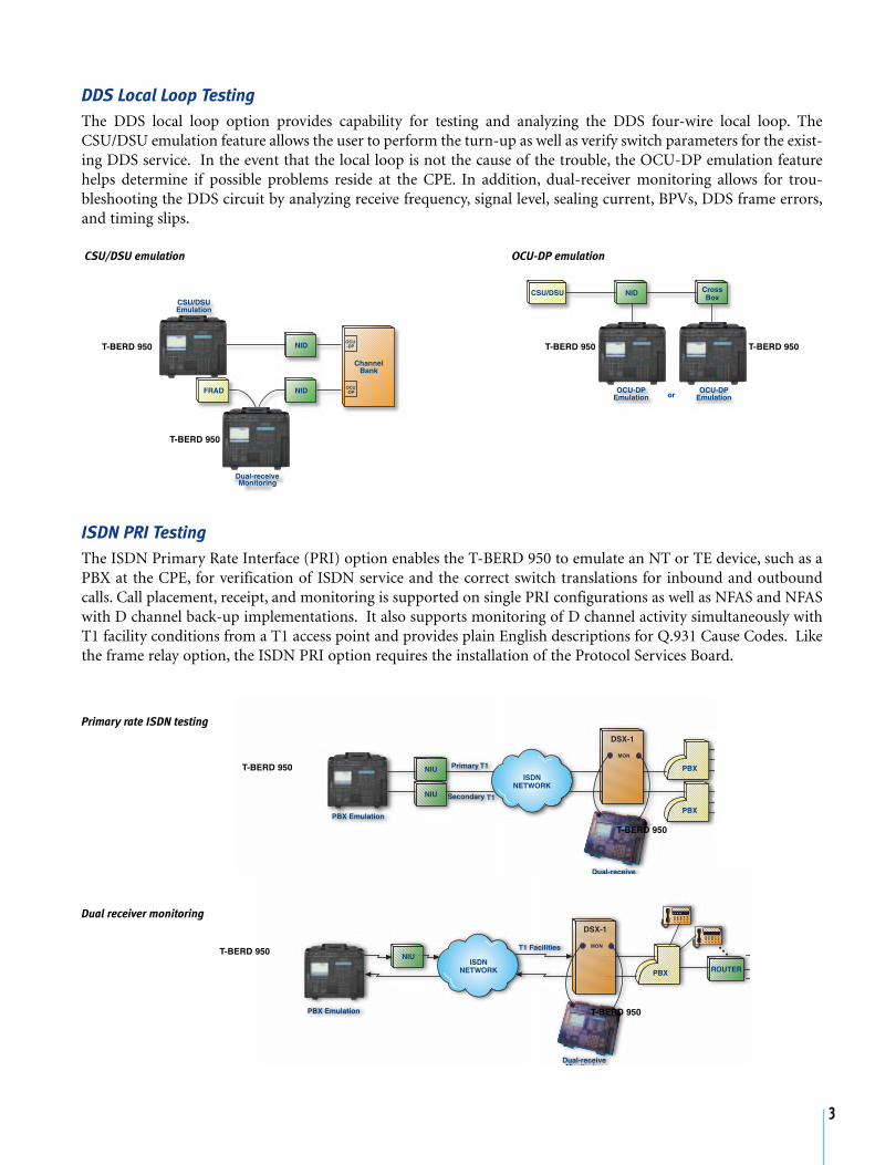
DDS Local Loop Testing
The DDS local loop option provides capability for testing and analyzing the DDS four-wire local loop. TheCSU/DSU emulation feature allows the user to perform the turn-up as well as verify switch parameters for the exist-ing DDS service. In the event that the local loop is not the cause of the trouble, the OCU-DP emulation featurehelps determine if possible problems reside at the CPE. In addition, dual-receiver monitoring allows for trou-bleshooting the DDS circuit by analyzing receive frequency, signal level, sealing current, BPVs, DDS frame errors,and timing slips.
ISDN PRI Testing
The ISDN Primary Rate Interface (PRI) option enables the T-BERD 950 to emulate an NT or TE device, such as aPBX at the CPE, for verification of ISDN service and the correct switch translations for inbound and outboundcalls. Call placement, receipt, and monitoring is supported on single PRI configurations as well as NFAS and NFASwith D channel back-up implementations. It also supports monitoring of D channel activity simultaneously withT1 facility conditions from a T1 access point and provides plain English descriptions for Q.931 Cause Codes. Likethe frame relay option, the ISDN PRI option requires the installation of the Protocol Services Board.
3
Dual receiver monitoring
OCU-DP emulation
Primary rate ISDN testing
T-BERD 950
T-BERD 950
T-BERD 950
T-BERD 950
CSU/DSU emulation
T-BERD 950 T-BERD 950
T-BERD 950
T-BERD 950

ISDN BRI Testing
The ISDN Basic Rate Interface (BRI) option, in conjunction with the Protocol Services Board option, enables theT-BERD 950 to perform BER testing, protocol analysis (D channel analysis), voice and data call placement andreceipt and X.25 D channel packet call analysis. The LT and the NT1 emulation features allow the user to performBER testing on the U interface toward the NT1 and toward the LT, respectively. In addition, the NT1/TE emulationprovides a tool for placing and receiving voice and data calls at the U interface.
Analog 2-Wire/4-Wire Testing
The T-BERD 950 Analog 2W/4W Interface Module provides technicians with the capability to perform installationand troubleshooting tests for analog voice, analog data, and digital data services. The module is an optional inter-face for the T-BERD 950 that can be used for the following test applications:
• TIMS pre-qualification of the copper pair for analog point-to-point service• TIMS pre-qualification for the copper pair for digital wide band service including DDS, ISDN, HDSL, and
IDSL• Testing of analog voice services including loop start, ground start, and DID through PBX emulation. (Note:
The current Analog 2-Wire/4-Wire Interface Module supports only DID PBX emulation).
4
Use the T-BERD 950 to BERTthe copper wire pair for ISDNBRI service
Use the T-BERD 950 to verifythe ISDN BRI voice and dataservice
Analog point-to-point service testing
Analog voice service testing
T-BERD 950
T-BERD 950
T-BERD 950
T-BERD 950
T-BERD 950

Datacom Testing
The Datacom (DTE/DCE) Interface Module is an optional interface module to the T-BERD 950. With this option,the user can perform BER or frame relay testing, or emulate the CPE. The Datacom (DTE/DCE) Interface Moduleallows the user to emulate a DTE or DCE, while dual–receiver monitoring supports full duplex monitoring at syn-chronous BER testing rates from 50 bps to 10 Mbps. Overall, this module allows the user to extend end-to-end test-ing at synchronous data rates by supporting the most common data interfaces.
Frame Relay Testing
Frame Relay testing is an option for the T-BERD 950 that requires installation of the Protocol Services Board. Itenables the user to perform frame relay service installation and maintenance from the T1, DDS-LL, and datacominterface. This option offers strong CPE emulation and dual receiver monitoring features. In addition, the framerelay option allows the user to perform link management emulation and test frame generation to verify LMI func-tionality, PVC status, and QoS.
5
CPE
CPECPE
EIA-232
RS-232
RS-449
V.35CPE
CSU
DSU
CSU
DSU
DataNetwork
MUX
Dual-receiveMonitoring
DTE/DCE Emulation
Point-to-point data testing
Packet switched data testing
Frame relay testing
T-BERD 950
T-BERD 950
T-BERD 950
T-BERD 950
T-BERD 950
T-BERD 950
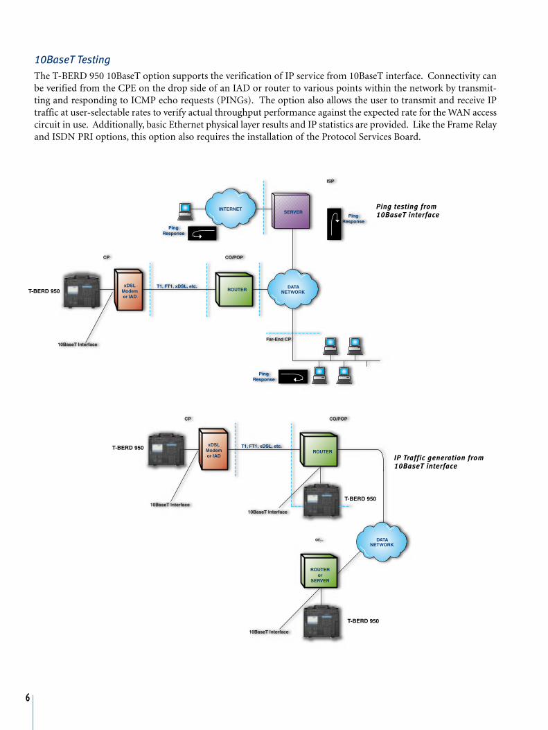
10BaseT TestingThe T-BERD 950 10BaseT option supports the verification of IP service from 10BaseT interface. Connectivity canbe verified from the CPE on the drop side of an IAD or router to various points within the network by transmit-ting and responding to ICMP echo requests (PINGs). The option also allows the user to transmit and receive IPtraffic at user-selectable rates to verify actual throughput performance against the expected rate for the WAN accesscircuit in use. Additionally, basic Ethernet physical layer results and IP statistics are provided. Like the Frame Relayand ISDN PRI options, this option also requires the installation of the Protocol Services Board.
6
T-BERD 950
T-BERD 950
T-BERD 950
T-BERD 950
Ping testing from10BaseT interface
IP Traffic generation from10BaseT interface

PCM TIMS TestingThe PCM TIMS option enables the user to perform testing on individual voice channels from a digital (T1) accesspoint. The PCM TIMS option operates in three different T1 configuration modes: terminate, drop and insert, ormonitor. End-to-end channel performance can be tested from the T1 access to ensure proper VF service quality.When this type of testing is performed on a VF channel, the T-BERD 950’s two T1 receivers allow non-intrusivePCM TIMS measurement with the presence of a variable frequency/level tone, holding tone, or quiet transmission.By performing the PCM TIMS measurement at various points along the T1 circuit, the user can differentiatebetween VF service and T1 transmission problems.
SignalingThe T-BERD 950 Signaling option allows the user to verify service when turning up a new T1 trunk and supportstroubleshooting of PBX to switch connections. The entire T1 trunk can be terminated for out of service testing ordrop and insert testing can be performed on a single DS0 channel. Proper PBX and switch operation can be veri-fied through call origination, call termination, signaling verification, and in-depth event and digit measurements.With two T1 receivers, the T-BERD 950 supports full duplex monitoring of signaling events and digits associatedwith a specific DS0.
TNT Task Based TestingThe T-BERD 950 currently supports six physical interfaces for testing, including T1, DDS Local Loop, Datacom(RS-232, EIA-53, RS-449, X.21 and V.35), Analog 2-wire/4-wire, BRI (U interface), and 10BaseT. TNT Task BasedTesting provides an efficient user interface, which simplifies turn-up and troubleshooting procedures for testing ofservices on all supported interfaces. By using the tasks and terminology typically employed by a technician, TNTTask Based Testing streamlines the testing process by reducing the number of configuration items and time requiredto obtain results.
7

8
Technical Specifications
PHYSICAL CHARACTERISTICS
Overall dimensions . . . . . . . . . . . . . . . . . . . . . . 10.5 x 13.25 x 4 in.
(26.8 x 33.66 x 10.17 cm)
Weight . . . . . . . . 10 lbs (4.55 kg) without batteries, 13 lbs (5.9 kg)
ENVIRONMENTAL
Temperature Range
Operating . . . . . . . . . . . . . . . . . . . 32° F to 122° F (0° C to +50° C)
Non-Operating . . . . . . . . . . . . . -4° F to 140° F (-20° C to +60° C)
Humidity . . . . . . . . . . . . . . . . 10% to 90% Relative Humidity, non
Vibration . . . . . . . . . . . . . . . . Per BellCore NEBS TR-EOP-000063
Shock . . . . . . . . . . . . . . . . . . . . . . . . . . . . . . . . . Per IEEE-743-1985
ALTITUDE
Operating . . . . . . . . . . . . . 200 ft. (61 m) below sea level to 16,400
Non-operating storage or transportation . . . 49,210 ft, (15,000 m)
POWER REQUIREMENTS
AC Power
Input Voltage . . . . . . . . . 90 to 240 VAC, 47 to 63 Hz, autodetected
Power Dissipation . . . . . . . . . . . . . . . . . 30 watts (typical), 68 watts(peak - two batteries receiving initial charge)
Fuse Type . . . . . . 250 Volt, 1 Amp Slo-Blo (LittleFuse p/n 218001)
DC Power
Battery Type. . . . . . . . . . . . . . Panasonic LCS-2012DP (2 required)
Operating Time . . . . . . . Depends on configuration, up to 4 hours
T1 SPECIFICATIONS
Operating Modes . . . . . . . . . . . . . . . . . . . . . . . Terminate (TERM),Drop & Insert (D&I), Monitor (MON), Line Loopback (LLB)
Framing . . . . . . . . . . . . . . . . . . . . . . ESF, SF, SLC, Unframed, Auto
T1 Input
Frequency . . . . . . . . . . . . . . . . . . . . . . . . . . . 1.544 MHz ±5000 Hz
Input Impedance
TERM. . . . . . . . . . . . . . . . . . . . . . . . . . . . . . . . . . . . 100 ohms ±5%
BRIDGE. . . . . . . . . . . . . . . . . . . . . . . . . . . . . 1000 ohms minimum
DSX-MON . . . . . . . . . . . . . . . . . . . . . . . . . . . . . . . . 100 ohms ±5%
Operating Range. . . . . . . . . . . . . . . . . . . . . . . . . . . . . . . . . . . . . . . . TERM . . . . . . . . . . . . . +6 dBdsx to -35.0 dBdsx cable attenuation
DSX-MON . . . . . . . . . . +6 dBdsx to 35.0 dBdsx cable attenuation
T1 OutputFrequency . . . . . . . . . . . . . . . . . . . . . . . . . . . . . . 1.544 MHz ±7 Hz
Clock Sources . . . . . . . . . . . . . . . . . . Internal Oscillator, Recovered
(from associated path receiver)
Line Build Out (LBO) . . . 0, -7.5, -15, -22.5 dB ± 1 dB at 772kHz
Operating Range. . . . . . . . . . . . . . . . . . . . . . . . . . . . . . . . . . . . . . . .
DSX MON . . . . . . . . -10 dBdsx to -30 dBdsx resistive attenuation
Line Coding . . . . . . . . . . . . . . . . . . . . . . . . . . . . . . . . . . AMI, B8ZS
Error Insert Type . . . . . . . . . . . . . . . . . BPV, Logic, Frame, L&BPV
(Logic and BPV errors)
Indicators . . . . . . . . . . . . Signal Present, Frame Sync, Pattern Sync,B8ZS Detect, AIS (Alarm Indication Signal) and Yellow Alarm
FREQUENCY MEASUREMENT
Accuracy . . . . . . . . . . . . . . . . . . . . . . . . . . . . . . . . . . . . . . ± 10 ppm
Resolution . . . . . . . . . . . . . . . . . . . . . . . . . . . . . . . . . . . . . . . . . 1Hz
Level
Peak to Peak . . . . . . . . . . . . . . . . . . . . . . . . . . . . . . 20mV to 12.0 V
Positive and Negative Base to Peak. . . . . . . . . . . . . . 10mV to 6.0 V
Positive and Negative Base to Peak . . . . -48.0 dBdsx to +6.7 dBdsx
Resolution1 . . . . . . . . . . . . . . . . . . . . . . . . . . . . . . . . . . . . . . . ±1 dB
Simplex Current
Range . . . . . . . . . . . . . . . . . . . . . . 10 to 207 mA, and under 10 mA
Accuracy . . . . . . . . . . . . . . . . ±10% or 2mA (whichever is greater)
Wander
Resolution . . . . . . . . . . . . . . . . . . . . . . . . . . . . . . . . . . . . . . . . . 1 UI
Accuracy . . . . . . . . . . . . . . . . . . . . . . . . . . . . . . . . . . . . . . . . . . 1 UI
DDS SPECIFICATIONS
Data Formats. . . . . . . . . . . . . . . . . . . . . . . Standard DDS and DDS
with Secondary Channel
Primary Channel Data Rates . . . . . . . . . 2.4, 4.8, 9.6, 19.2, 38.4, 56,
and 64 kbps
Secondary Channel Data . . . . . . . . . . . . . . . . . . Idle, 511, and 2047
BER testing patterns are available
Clock Source . . . . . . . . . . . . . . . . . . . . . . . . . . . . Internal OscillatorRecovered timing from received signal
Receive Signal
Connection . . . . . . . . . . . . . . . . OCU-DP mode: RJ-45 pins 1 & 2,DSU/CSU mode: RJ-45 pins 7 & 8,
Monitor mode . . . . . . . . . . . . . . . . . . . RJ-45 pins 1& 2 and 7 & 8
Termination Impedance . . . . . . . . . . . . . . . . Balanced, 135 Ω ±5%
Bridging Impedance . . . . . . . . . . . . . . . . . . . . Greater than 1900 ΩOperating Range . . . . . . . . . . . . . . . . +6.0 dB to -45 dB minimum
(56 kbps and 64 kbps) -OR- +6.0 dB to -40 dB minimum
(all other data rates)

9
Transmit Signal
Connection . . . . . . . . . . . . . . . . OCU-DP mode: RJ-45: pins 7 & 8DSU/CSU mode: RJ-45: pins 1& 2
Termination Impedance
Output Levels . . . . . . . . . . . . . . . . . . . . . . . . Balanced, 135 W, ±5%
Output Levels. . 0, -3, -6, and -9 dB of simulated cable attenuation
Test Modes . . . . TERMINATE, MONITOR, Line Loop Back (LLB)
Emulation Modes. . . . . . . . . . . . . DSU/CSU, OCU-DP or Metallic
Simplex Current
Input Level. . . . . . . . . . . . . . . . . . . . . . . . . . . . . ±30 mA maximum
Measurement range. . . . . . . . . . . . . . . . . . . . . . . . . . . . . . . ±26 mA
with an accuracy of ±10% or 2mA
OCU-DP mode current output . . . . . . . . . . . . . . ≥ 4 mA to 20 mA
depending on span length
Error Insertion
Operation . . . . . . . . . . . . . . . . . . . . . . . . . . . . Single or continuous
Error insert type . . . . . . . . . . . . . . . . Logic, BPV, L&BPV, or Frame
Loop Response . . . . . . . . . . . . . . . . . . . . . . . . . . . . . . . . . . . . . V.54,
DSU/CSU,Disabled
FRAME RELAY SPECIFICATIONS
Test Modes. . . . . . . . . . . . . . . . . . . . . . . . . . . . . . . . . . . . Terminate,Drop & Insert (T1 Interface only),
Monitor
Link Management Analysis . . . . . . . . LMI Rev.1, T1.617 Annex D,
Auto, None
PING Testing . . . . . . . . . . . . . . . . . . . . . . . . . . . . . ICMP Echo TestNLPID Encapsulation
ISDN BRI U INTERFACE SPECIFICATIONS
Interface. . . . . . . . . . . . . . . . . . . U Interface with To LT and To NT
Devices. . . . . . . . . . . . . . . . . . . . . . . . . . . . . . . . . . . . . . . . . . . . NT1
Physical Configuration . . . . . . . . Point to Point, Synchronous andFull-Duplex
Bit Rate . . . . . . . . . . . . . . . . . . . . . . . . . . . . . . . . . . . . . . . . 160 kbps
User Data Rate . . . . . . . . . . . . . . . . . . . . . . . . . . . . . . . . . . 144 kbps
Line Coding . . . . . . . . . . . . . . . . . . . . . . . . . . . . . . . . . . . . . . . 2B1Q
Line Rate. . . . . . . . . . . . . . . . . . . . . . . . . . . . . . . . . . . . . . . 192 kbps
Maximum Voltage . . . . . . . . . . . . . . . . . . . . . . . . . . . . . . . . ± 2.5 V
10BASET/ETHERNET SPECIFICATIONS
Test Modes . . . . . . . . . . . . . . . . . . . . . . . . . . . . . . . . . . . . Terminate
DHCP Implementation . . . . . . . . . . . . . . . . . . . . . . . . . . RFC 2131
PING Testing . . . . . . . . . . . . . . . . . . . . . . . . . . . . . ICMP Echo Test
Traffic Generation
Load Rate . . . . . . . . . . . . . . . . 1 kbps to 10 Mbps (User Selectable)
Packet Length . . . . . . . . . . . . . . . 70 to 1518 bytes (User Selectable)
ANALOG MODULE SPECIFICATIONS
Interfaces
Two Bantam connectors . . . . . . . . . . . . . . . . . . . . . . . . . . . . . . . . . . 2-wire alternate Transmit and Receive on the 2W/4W Tx
connector. 4-wire simultaneous Transmit on the 2W/4W Txconnector and Receive on the 4W Rx connector
Termination Impedance. . . . . . . . . . . . . . . 135 Ω, 600 Ω, or 900 ΩLoopbacks . . . . . . . . . . . . . . . . . . . . . . . . . . . . . . . . Tx VF Loop Up
Tx VF Loop Down
2713 Hz Loopback response
Level . . . . . . . . . . . . . . . . . . . . . . . . . . . . . . . . . . . . 10 dB to -30 dB
Frequency . . . . . . . . . . . . . . . . . . . . . . . . . . . . . 2706 Hz to 2720 Hz
Receive Holding Tone
Frequency . . . . . . . . . . . . . . . . . . . . . . . . . . . . . . . . . . . . . . 1004 Hz
Level . . . . . . . . . . . . . . . . . Controllable from +10 dBm to -40dBm
Stability . . . . . . . . . . . . . . . . . . . . . . . . . . . . . . . . . . . . . . ±0.005 Hz
Ring Detection (2 Wire Only) . . . . . . . . . . . . . . . . . . 40 V to 150 V
RMS ringing signal, 16 Hz to 68 Hz
Line Holding Current . . . . . . . . . . . . 26 mA DC, -8.6 V to -56.7 V
(Signaling or Signaling plus TIMS)
Dial and Receive Digit Types
DP. . . . . . . . . . . . . . . . . . . . . . . . . . . . . . . . . . . . . . . . . . . Dial Pulse
DTMF . . . . . . . . . . . . . . . . . . . . . . . . . . Dual Tone Multifrequency
MF . . . . . . . . . . . . . . . . . . . . . . . . . . . . Multifrequency (DID only)
DATACOM MODULE SPECIFICATIONS
Interface
EIA-232-D . . . . . . . . . . . . . . . . . . . . . . . Supports EIA-232-D/V.24/
V.28 - BA, BB, CA, CB, DD, CF, DB,
DD, LL, RL, CD, DA and TM
EIA-530 . . . . . . . . . . . . . . . . . . . . Supports EIA-422-B for BA, BB,CA, CB, CC, CD, CF, DA, DB, and DD
Supports EIA-423-B for LL, RL and TM
RS-449 . . . . . . . . . . . . . . . . . . . . . Supports EIA-422-B for SD, RD,RS, CS, DM, TR, RR, RT, ST and TT
Supports EIA-423-B for LL, RL and TM (Requires DB25 to DB37 adapter for EIA-530 Connector)
V.35/306 . . . . . . . . . . . . . . . . . . . Supports balanced clock and datacircuits, and EIA-232/ V.24/V.28 control circuits
Supports 306 for SCT, SCTE, SCR, SD and RDSupports V.35 for 103, 104, 114 and 115Supports V.28 for 105, 106, 107 and 109
X.21 . . . . . . . . . . . . . . . . . . . . . . Supports V.11 for R, I, S, T and C
Data Rates . . . . . . . . . . . . . . . . . . . . . . . . . . . . . . . . . . . . . . EIA-232
Max. Synchronous Data Rate: . . . . . . . . . . . . . . . . . . . . . . 128 kbps
Max. Recovered Data Rate: . . . . . . . . . . . . . . . . . . . . . . . . 128 kbps
RS-449 Terminated
Max. Synchronous Data Rate . . . . . . . . . . . . . . . . . . . . . . . 10 Mbps
Max. Recovered Data Rate . . . . . . 512 kbps RS-449 Unterminated
Max. Synchronous . . . . . . . . . . . . . . . . . with cable characteristics

Max. Recovered . . . . . . . . . . . . . . . . . . . . . . . . . . . . . . . . . 512 kbps
EIA-530 Terminated
Max. Synchronous Data Rate . . . . . . . . . . . . . . . . . . . . . . 10 Mbps
Max. Recovered Data Rate . . . . . . . . . . . . . . . . . . . . . . . . 512 kbps
EIA-530 Unterminated
Max. Synchronous. . . . . . . . . . . . . Varies with cable characteristics
Max. Recovered. . . . . . . . . . . . . . . . . . . . . . . . . . . . . 512 kbps. X.21
Max. Synchronous. . . . . . . . . . . . . Varies with cable characteristics
Max. Recovered . . . . . . . . . . Varies with cable characteristics. V.35
Max. Synchronous. . . . . . . . . . . . . Varies with cable characteristics
Max. Recovered . . . . . . . . . . 512 kbps.V.35-306 Max. Synchronous
Data Rate . . . . . . . . . 5 Mbps Max. Recovered Data Rate: 512 kbps
Test Modes . . . . . . . . . . . . . . . . . . . . . . . . . . . . . . . . . . . . . . . BERT,Frame Relay
Clock Source
Tx Timing . . . . . . . . . . . . . . . . . . . . . Interface, internal synthesizer
recovered from received data
Rx Timing . . . . . . . . . . . . . . . . . . . . . . . . . . . . . . Interface, internal
synthesizer recovered from the received data or automaticOperation Modes. . . . . . . . . . . . . . . . . . . . . . . . . . DCE Emulation,
DTE Emulation,Monitor
Ordering Information
Mainframe/Interface ModulesTB950-ANLG Analog (2W/4W) Interface ModuleTB950-DATA Datacom (DTE/DCE) Interface Module
OptionsTB950-BRI* Basic Rate ISDNTB950-LL DDS Local LoopTB950-10BT* Ethernet 10BaseTTB950-FR* Frame RelayTB950-SIG PCM SignalingTB950-TIMS PCM TIMS
TB950-PRI* Primary Rate ISDNTB950-PSB Protocol Services Board
Upgrade AccessoriesTB950-BATT Batteries (2)CC-43823 Soft Carrying CaseCC-44542 Padded Shipping CaseBC-44005 External Battery Charger
*Requires TB950-PSB
10

11
950D
S/A
/LL/
GE
R/3
-01
TTC AND WWG ARE NOW ACTERNA. TO LEARN MORE, VISIT WWW.ACTERNA.COM
Acterna is present in more than 80 countries. To find your local sales office, go to www.acterna.com
Regional Sales HeadquartersGlobal Headquarters20400 Observation DriveGermantown, Maryland 20876-4023 USAToll Free 1-800-638-2049 Tel +1-301-353-1550 Fax +1-301-444-8468 www.acterna.com
North America20400 Observation DriveGermantown, Maryland 20876-4023 USAToll Free 1-800-638-2049Tel +1-301-353-1550Fax +1-301-444-8468
Latin AmericaAv. Eng. Luis Carlos Berrini936 8/9. Andar04571-000 Sao Paulo, SPBrazilTel +55 11 5503 3800 Fax +55 11 5505 1598
Asia/Pacific42 Clarendon StreetPO Box 141South Melbourne, Victoria 3205AustraliaTel +61 3 9690 6700 Fax +61 3 9690 6750
Western EuropeArbachtalstrasse 672800 Eningen u.A.GermanyTel +49 7121 86 2222 Fax +49 7121 86 1222
Eastern Europe, Middle East & AfricaElisabethstrasse 36PO Box 132500 BadenAustriaTel +43 2252 85 521 0 Fax +43 2252 80 727
1st Neopalimovskiy Per. 15/7 (4th floor)119121 MoscowRussiaTel +7 095 248 2508 Fax +7 095 248 4189
Note: Specifications, terms, and conditions are subject to change without notice.
Copyright 2001, Acterna, LLC. All rights reserved. Acterna, The Keepers ofCommunications, its logo are trademarks, and T-BERD 950 is a registered trademark ofActerna, LLC. All other trademarks are the property of their respective owners.