t figure c2 - university of the witwatersrand
TRANSCRIPT

TFIGURE C 2

(P /P )< = 0,452 c p
I I
FIGURE C3
i I
FIGURE i:4

From f i gu re C.4 there fore , the f a i lu r e load as a percentage o f the
p las t ic co l lapse load is 0,73, i * e . the expected f a i lu r e load
using Schol : ' in teract ion formula is 111 kg/bay.
Failure loads predicted by Scho l l ' method, fo r the frames tested,
were calculated in the same manner.

CALCULATION OF LOADING POINTS TO SIMULATF APPKNDIX D
A UNIFORMLY DISTRIBUTED LOAD
The loading pattern i l lu s t ra ted in f igu re D.l is used to simulate
a uniformly d is tr ibuted load applied to the r a f t e r s .
In the above diagram:
P » to ta l load on the span
* w x L
w = equivalent uniformly d is tr ibuted lead.
A comparison o f the f ree bending moment diagram, and f i .*oj-ended
moments wi l l show that the loading i l lu s t ra ted accurately
simulates a uniformly d is tr ibuted
Comparison of Free Bending Moment Diagrams
f i gu re D.2 g ives a comparison between bending moment under a
uniformly d is tr ibuted load and under the loading used in the
laboratory tes ts .

Comparison of Fixed-ended Moments
For a uniformly d is tr ibuted load, the f ixed-ended moment is
M = wL2 /l 2
= 0,0833wLl
Assuming that the point loads i l lu s t ra ted in f i gu re P .l also y i e ld
a fixed-ended moment o f 0.0*33*1- . rhe bending moment diagram
shown in f igure P .3 is obtained.
FIGL'RE DJ
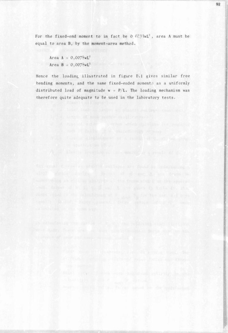
For the f ixed-end momert to in fac t be 0 OP.HwL , area A must be
equal to area B, by the moment-area method.
Area A = 0,0079wL*
Area B * 0,007^wL
Hence the loading i l lu s t r a t ed in f igu re D.l g ives s im ilar f ree
bending moments, and the same f ixed-ended momenta as a uniformly
d is t r ibu ted load of magnitude w P/L. The loading mechanism was
there fore quite adequate to be used in the laboratory te s ts .

CALCULATION OF THE RAT/OS OF P J P AND APPENDIX Ec snap pP J P , USiNC THE APPROXIMATE ENERGY
c swajr pMETHOD AND HORNE'S ASSUMPTIONS
The equ. 'ised to ca lcu la te the ra t io o f P p is:’ c p
> 4 ( i ), « ? )
P Elastic buckling load o f the framec
P = P last ic co l lapse load P
R: Axial load in member at p las t ic col lapse (newtons)
Lj Length o f each membe * (m i l l im etres )
Q = Applied s'xternal forces which i n i t i a t e the required
mode of f a i lu r e i . e . snap-through or sway
A = Elast ic displacement as a result of Q, at the point
o f app l icat ion o f Q.
0, - Elastic ' t a t : n o f each member as a result o f Q.
The ax ia l forces at p la s t i c co l lapse are found by undertaking a
simple p last ic ana lyr is . Values of /3 and A are found by
undertaking an e la s t i c analys is o f the frame with Q as the applied
load. Values of R. l, Q, (3 and A are given in Table El. Also
illustrated is the calculation of P P for the case ail baysc sway p equally loaded, bases pinned. Other rat ios o f
calculated in the same way.
In ca lculat ing the ra t ios o f P P , the fo l low ing s im p l i f i ca t ion s
were made. These are the same s im p l i f ica t ions Horne used in his
research o f sway and snap-through s t a b i l i t y .
F irs t order s t i f fn e s se s , i . e . EI/'L were used. The
s t i f fn ess reducing e f f e c t of ax ia l forces was there
fore ignored.
Axial r a f t e r forces were neglected e n t i r e l y in the
calcula t ion o f the P /P ra t ios .c sway p
Average axial rafter forces based on the undeformed

structure were used in ca lcu la t ing the P /Pc snap pvalues.
The e f f e c t o f r a f t e r shortening, as a result o f the
frames d e f l e c t io n under the applied load, was not.
considered.
Ax ial r a f t e r forces at the e la s t i c c r i t i c a l buculing
load were assumed to be proportional to those at
r i g id -p la s t i c co l lapse .


KXAMPLE OF THE INTKRACTION EQUATION IN
BS5950, TO PREVENT MEMBER INSTABILITY'
APPENDIX F
To prevent indiv idual member i n s t a b i l i t y , the fo l low ing in t e r
action equation must be applied to c r i t i c a l members within a
f rame.
Max May
m - uniform moment fac to r obtained from Tab3 .* 18 in BS5950
Mx = applied moment about the major a\is at the c r i t i c a l
section
My * applied moment about the minor axis at the c r i t i c a l
sect ion
Max = maximum al lowable buckling moment about the major axis in
the presence o f ax ia l load
May = maximum al lowable buckling moment about ihe minor axis in
the presence o f ax ia l load
Since a l l framei tested in the laboratory were bent about the
minor axis only, the in t * i 3 't.ion equation ’"educes to:
R * applied ax ia l loao in the c r i t i c a l section
Rcy = compressive res istance o f the sect ion about the minor axis
Mcy =■ p las t ic moment capacity o f the sect ion calculated from
m.Mx + m._Mv < 1( 1 )
m.Mv < 1 (2 )May
May is ca lculated usini; equation (3 )
May = Mcy( 1 - 3 7 W R c y » (3 )
clause 4.2.5 or 4-2.6 in BS5950.
Since the case a l l bays equally loaded a l l bases pinned, v,as
considered in the other appendices, the interaction equation w i l l
be applied to th is frame. The bending moment diagram under t.it

r i g id -p la s t i c co l lapse load is given in f i gu re F .1.
FIGL R E FI
The c r i t i c a l member in the frame is PF as i l lu s t r a t e d . The ax ia l
fo rce in this member is 739 N.
Calculation of the Numerator in Equation (2)
From Table 18 o f BS5950, m = 0,43
Since the greatest moment in the c r i t i c a l sect ion is Mp the
numerator of equation (2 ) is 0,43Mp
Calculation of the Denomenator in Equation (2)
Calculat ion o f Mcy:
The value o f Mcy depends on the shear capacity o f the sect ion.
Shear capacity 0.6*(7y*Av
Av s 0.9 An 0.0x20x5 90mnr
Hence shear capacity is:

0.6x3,34*90 1S036 N
I f the maximum shoar in the r a f t e r is < 0.6 times the shear
capacity o f the sect ion; Mcy = Mp.
The maximum shear force applied to member DF. from f igu re P . I , is
746 N which is smaller than 0.6 times the shear capacity o f the
ra f t e r .
Therefore Mcy = Mp, the p las t ic moment.
Calculation o f Rcy:
The compressive res is tance Rcy of the r a f t e r is obtained from:
Rcy = Ag.Ocy
<7cv = al lowable compressive stress o f the section about the miner
ax is .
Ocy depends on the y i e ld stress Oy and the slenderness o f the
member. Assuming an e f f e c t i v e length fa c to r o f 1, table 27(b) o f
BS505O g ives fo r a y i e ld stress o f 334 N/rrun* :
4 1 •5 ̂ mm
loe re fo re Rcy is:
30x41.? = 41 SO N
.Subst i tut inn R 739 N, Rcy = 41 SO N and Mcy ■■ Mp into equation
(3 ) g ives fo r May:
May * 0.75S Mp
Substituting May into equation (2 ) g ives:
0.43Mp « 0.S7 O.K.0.7S5Mp

From the in teract ion equation i t appears that member in s t a b i l i t y
is not a problem. This tvpe o f f a i lu r e should not occur in the
given frame.

REFERENCES
1.
2 .
3.
4- Scholz, H.
5. Scholz, H.
6. Merchant, W.
7 • Wood , fl. H.
8 . Scholl , H.
9. Kemp, A.R.
Structural lise of Steelwork in Bui ld ing Part1, BS 5O5O. London, Bri t ish .Standards Instl tu- t ion, 10^ ' .
Safeguards Against Frame In s ta b i l i t y in the Pl a s t i c Design o f Single Storey Pitched-rooT Frames, Conference or Slender Structures, City I’n i v e r s i t y , Sept 1977. unpublished paper.
SABS 0162-19*4, Code of Practice fo r__ t heStructural I'se of Sreel , f i r s t rev is ion , South A f r i c in Bureau o f Standards, Pretor ia , 1Q84*
A Re-apprais 1 of the Elastic Buckling Load of Pitched-root Frames, Part i o? Proceedings, Internat ional Conference on Steel Structures - Recent Research Advances, Budva, Sept 28-Oct1. 19*6, pp 35-42.
E last ic Snap-thrjugh Bu.'kling Load of Pirched- roof Steel Frames, I 'n ive ic i ty o7 the Wit- watersrand, Johannesburg, unpublished, 1986.
The Fai lure Load of R ig id- jo in ted Framework as influenced by S t a b i l i t y , The Structural Fngin- eer. Vol. ',2 1054 , pp""" 185-190.
E f f e c t i v e Lengths of Columns in Multi-storey Bui 1d i ngs. Proceed ings Inst i tu t ion oT C i v i l Engineers, 1074 , \^1. 52, p p 2 ^ , 29b. 341*
A New Mult i-curve Interaction Method f o r the P las t ic Ana lysis and Pesign o f ~ l ;nhraced and Part j 11ly-braced Frames, PhP Thesis, Ini vers i f y of1 the Witwatersrand. Johannesburg, Pec 19*1.
\ Consistent Mixed Approach to Computer Analysis of Frames, University of the Wit- watersrand. Johannesburg, unpublished, 19*6.

.
102
10. American Ins t i tu te of Stee l Construction,Spec i f i ca t ion fo r the Design, Fabricat ion and Erection of Structural Steel fo r Build ings , New Yorlc, August 197^*
11. Anderson, D. F i rs t -o rder P las t ic Design of Single StoreyPinned-base Frames, Document oT ECCS Working Group TW<5 5.2. May 19^6.
12. Commentary on SABS 0162-H84, Code of Pract icef o r the Structural Use of S t e e l , South African Ins t i tu te o f Steel Construct ion, Johannesburg, Republic o f South A f r ica , 1985.


Author Bryant John Spencer Name of thesis The Snap-through Stability Of Plastically Designed Steel Pitched-roof Portal Frames. 1987
PUBLISHER: University of the Witwatersrand, Johannesburg
©2013
LEGAL NOTICES:
Copyright Notice: All materials on the Un i ve r s i t y o f the Wi twa te r s rand , Johannesbu rg L ib ra ry website are protected by South African copyright law and may not be distributed, transmitted, displayed, or otherwise published in any format, without the prior written permission of the copyright owner.
Disclaimer and Terms of Use: Provided that you maintain all copyright and other notices contained therein, you may download material (one machine readable copy and one print copy per page) for your personal and/or educational non-commercial use only.
The University of the Witwatersrand, Johannesburg, is not responsible for any errors or omissions and excludes any and all liability for any errors in or omissions from the information on the Library website.