t hr rs 00300 st rsu 300 series – minimum operating
TRANSCRIPT
RSU 300 Series – Minimum Operating Standards for Rolling Stock – Locomotive Specific Interface Requirements
T HR RS 00300 ST
Standard
Version 2.0
Issue date: 10 April 2019
© State of NSW through Transport for NSW 2019

T HR RS 00300 ST RSU 300 Series – Minimum Operating Standards for Rolling Stock – Locomotive Specific Interface Requirements
Version 2.0 Issue date: 10 April 2019
Important message This document is one of a set of standards developed solely and specifically for use on
Transport Assets (as defined in the Asset Standards Authority Charter). It is not suitable for any
other purpose.
The copyright and any other intellectual property in this document will at all times remain the
property of the State of New South Wales (Transport for NSW).
You must not use or adapt this document or rely upon it in any way unless you are providing
products or services to a NSW Government agency and that agency has expressly authorised
you in writing to do so. If this document forms part of a contract with, or is a condition of
approval by a NSW Government agency, use of the document is subject to the terms of the
contract or approval. To be clear, the content of this document is not licensed under any
Creative Commons Licence.
This document may contain third party material. The inclusion of third party material is for
illustrative purposes only and does not represent an endorsement by NSW Government of any
third party product or service.
If you use this document or rely upon it without authorisation under these terms, the State of
New South Wales (including Transport for NSW) and its personnel does not accept any liability
to you or any other person for any loss, damage, costs and expenses that you or anyone else
may suffer or incur from your use and reliance on the content contained in this document. Users
should exercise their own skill and care in the use of the document.
This document may not be current and is uncontrolled when printed or downloaded. Standards
may be accessed from the Transport for NSW website at www.transport.nsw.gov.au
For queries regarding this document, please email the ASA at [email protected] or visit www.transport.nsw.gov.au © State of NSW through Transport for NSW 2019

T HR RS 00300 ST RSU 300 Series – Minimum Operating Standards for Rolling Stock – Locomotive Specific Interface Requirements
Version 2.0 Issue date: 10 April 2019
Standard governance
Owner: Lead Rolling Stock Engineer, Asset Standards Authority
Authoriser: Chief Engineer, Asset Standards Authority
Approver: Executive Director, Asset Standards Authority on behalf of the ASA Configuration Control Board
Document history
Version Summary of changes
1.6 Original RailCorp Engineering Standard ESR 0001-300 renumbered to T HR RS 00300 ST as per TN 097:2014
2.0 Second issue April 2019 Updated as shown in the summary table in the Preface
© State of NSW through Transport for NSW 2019

T HR RS 00300 ST RSU 300 Series – Minimum Operating Standards for Rolling Stock – Locomotive Specific Interface Requirements
Version 2.0 Issue date: 10 April 2019
Preface The Asset Standards Authority (ASA) is a key strategic branch of Transport for NSW (TfNSW).
As the network design and standards authority for NSW Transport Assets, as specified in the
ASA Charter, the ASA identifies, selects, develops, publishes, maintains and controls a suite of
requirements documents on behalf of TfNSW, the asset owner.
The ASA deploys TfNSW requirements for asset and safety assurance by creating and
managing TfNSW's governance models, documents and processes. To achieve this, the ASA
focuses on four primary tasks:
• publishing and managing TfNSW's process and requirements documents including TfNSW
plans, standards, manuals and guides
• deploying TfNSW's Authorised Engineering Organisation (AEO) framework
• continuously improving TfNSW’s Asset Management Framework
• collaborating with the Transport cluster and industry through open engagement
The AEO framework authorises engineering organisations to supply and provide asset related
products and services to TfNSW. It works to assure the safety, quality and fitness for purpose of
those products and services over the asset's whole-of-life. AEOs are expected to demonstrate
how they have applied the requirements of ASA documents, including TfNSW plans, standards
and guides, when delivering assets and related services for TfNSW.
Compliance with ASA requirements by itself is not sufficient to ensure satisfactory outcomes for
NSW Transport Assets. The ASA expects that professional judgement be used by competent
personnel when using ASA requirements to produce those outcomes.
About this document
This document provides the minimum operating standards for rolling stock to operate on the
TfNSW Metropolitan Heavy Rail Network. The document specifies the locomotive specific
interface requirements to ensure that all rolling stock operating on the TfNSW Metropolitan
Heavy Rail Network are compatible with the network and its infrastructure.
This document supersedes RailCorp standard ESR 0001-300, RSU 300 – Minimum Operating
Standards for Rolling Stock – Locomotive Specific Interface Requirements, version 1.6
(ESR 0001-300 was renumbered to T HR RS 00300 ST in an ASA technical note in 2014).
This document is the first ASA issue and there are no major changes in technical requirements.
The changes to previous content include the following:
• replacement of RailCorp organisation roles and processes with those applicable to the
current ASA organisational context
• amendments and clarification to content (refer to the summary of changes in Table 1) © State of NSW through Transport for NSW 2019 Page 4 of 51

T HR RS 00300 ST RSU 300 Series – Minimum Operating Standards for Rolling Stock – Locomotive Specific Interface Requirements
Version 2.0 Issue date: 10 April 2019
• conversion of the standard to ASA format and style
Table 1 provides a summary of changes to the content of this standard from the previous
version. Changes to front matter, formatting, branding, and governance are not included.
Table 1 Summary of changes from ESR 0001 – 300 Version 1.6 (June 2013)
Page Section Change
13 2.2 Added new section referencing wheel profiles
17 3.8 Clarified ECP brakes and added function test
21 5.4 Amended 30 mm to 40 mm to take into account track infrastructure - refer to ESC 215 for more information
21 5.5 Clarified text height for number lights, text height for generic markings, added ASA to provide TfNSW locomotive codes and numbers
22 5.5.3 Clarified end visibility
26 6.5 Added P/D reference
26 6.6 Added bridge loading requirement references
29 7.5 Wheel creep requirements clarified (table and figures removed)
29 7.6 Clarified dynamic brake and removed figure
30 7.10 Clarified acceptance criteria in line with T HR RS 40001 PR
32 8 Clarified static and dynamic brake testing requirements
33 8.2 Added reference to T HR RS 00830 ST
34 8.3 Added clarification on automatic brake performance and driver safety systems
38 10.3 Updated rail regulator name and link for compliance code
39 10.8.3 Corrected marker light requirements from 0.75 Cd to 75 Cd and height
41 10.9 Updated horns to allow shorter test distances and added upper limit for country horns
47 16 Updated section and included all requirements for wired distributed power (WDP)
48 17 New section added to provide specific clarification for locomotives used for high-speed passenger service
© State of NSW through Transport for NSW 2019 Page 5 of 51

T HR RS 00300 ST RSU 300 Series – Minimum Operating Standards for Rolling Stock – Locomotive Specific Interface Requirements
Version 2.0 Issue date: 10 April 2019
Table of contents 1. Locomotive specific interface requirements – RSU 300 ..................................................................... 9 1.1. Introduction ........................................................................................................................................... 9 1.2. Purpose ................................................................................................................................................ 9 1.3. Application ............................................................................................................................................ 9 1.4. Reference documents......................................................................................................................... 10 1.5. Australian standards for railway rolling stock ..................................................................................... 11
2. Bogie components – RSU 310 .............................................................................................................. 13 2.1. Wheels ................................................................................................................................................ 13 2.2. Wheel profiles ..................................................................................................................................... 13 2.3. Axles ................................................................................................................................................... 13 2.4. Wheel and axle assembly ................................................................................................................... 13 2.5. Axle bearing assemblies ..................................................................................................................... 13 2.6. Bogie frames and associated componentry ....................................................................................... 13 2.7. Vehicle suspension ............................................................................................................................. 13
3. Brakes and pneumatic equipment – RSU 320 .................................................................................... 14 3.1. General requirements ......................................................................................................................... 14 3.2. Location of end equipment ................................................................................................................. 14 3.3. Standard pressures and timings ......................................................................................................... 15 3.4. Brake equipment ................................................................................................................................. 16 3.5. Identification of cocks ......................................................................................................................... 16 3.6. Air dryers ............................................................................................................................................ 16 3.7. Dummy couplers ................................................................................................................................. 17 3.8. ECP brakes ......................................................................................................................................... 17
4. Dynamic / regenerative brake – RSU 321 ............................................................................................ 18
5. Body and underframe – RSU 330 ......................................................................................................... 19 5.1. Design loads and stresses ................................................................................................................. 19 5.2. Couplers and draft gear ...................................................................................................................... 20 5.3. Toilets ................................................................................................................................................. 21 5.4. Cowcatcher or pilot ............................................................................................................................. 21 5.5. Marking and identification ................................................................................................................... 21 5.6. Cab security ........................................................................................................................................ 23 5.7. Jumper couplings ................................................................................................................................ 23 5.8. Fire resistance .................................................................................................................................... 24
6. Vehicle performance – RSU 340........................................................................................................... 25 6.1. Test requirement summary ................................................................................................................. 25 6.2. Jacking point vertical load test ............................................................................................................ 26 6.3. Static end compression test ............................................................................................................... 26 6.4. Single vehicle impact .......................................................................................................................... 26 6.5. P2 force determination and P/D ratio .................................................................................................. 26 6.6. Locomotive weigh test, mass and axle loads ..................................................................................... 26 © State of NSW through Transport for NSW 2019 Page 6 of 51

T HR RS 00300 ST RSU 300 Series – Minimum Operating Standards for Rolling Stock – Locomotive Specific Interface Requirements
Version 2.0 Issue date: 10 April 2019
7. Traction performance – RSU 341 ......................................................................................................... 28 7.1. Introduction ......................................................................................................................................... 28 7.2. Sanding ............................................................................................................................................... 28 7.3. Wheelslip control ................................................................................................................................ 28 7.4. Locomotive configuration – traction control software ......................................................................... 29 7.5. Wheel creep ........................................................................................................................................ 29 7.6. Dynamic brake performance .............................................................................................................. 29 7.7. Longitudinal rail force.......................................................................................................................... 29 7.8. Traction performance test ................................................................................................................... 30 7.9. Traction performance test - method ................................................................................................... 30 7.10. Traction performance tests – acceptance criteria .............................................................................. 30 7.11. Setting maximum load ........................................................................................................................ 31 7.12. Consultation ........................................................................................................................................ 31
8. Braking performance – RSU 342 .......................................................................................................... 32 8.1. Static brake test .................................................................................................................................. 32 8.2. On track brake performance (light locomotives) ................................................................................. 33 8.3. Operation of driver safety systems ..................................................................................................... 34 8.4. Locomotives to be hauled dead attached ........................................................................................... 34
9. Locomotive ride performance – RSU 343 ........................................................................................... 35 9.1. Base ride performance requirements ................................................................................................. 35 9.2. Recommended ride performance requirements ................................................................................. 35 9.3. Ride index algorithm ........................................................................................................................... 35
10. Safety equipment – RSU 350 ................................................................................................................ 37 10.1. Driver safety systems ......................................................................................................................... 37 10.2. Speed indicating device ...................................................................................................................... 37 10.3. Data logger or recorder ...................................................................................................................... 38 10.4. Drivers emergency cock ..................................................................................................................... 38 10.5. Flowmeter ........................................................................................................................................... 38 10.6. Emergency equipment ........................................................................................................................ 38 10.7. Communications ................................................................................................................................. 38 10.8. Lights .................................................................................................................................................. 39 10.9. Horn .................................................................................................................................................... 41
11. Locomotive type specific requirements – RSU 360 ........................................................................... 43
12. Diesel electric and diesel hydraulic locomotives – RSU 361 ............................................................ 43 12.1. Hauling a dead diesel or hydraulic locomotive ................................................................................... 43 12.2. Spark arresters ................................................................................................................................... 43
13. Electric locomotives – RSU 362 ........................................................................................................... 44 13.1. Pantograph isolation ........................................................................................................................... 44 13.2. Use of multiple pantographs ............................................................................................................... 44 13.3. Energy consumption meter ................................................................................................................. 44
14. Steam locomotives – RSU 363 ............................................................................................................. 45
© State of NSW through Transport for NSW 2019 Page 7 of 51

T HR RS 00300 ST RSU 300 Series – Minimum Operating Standards for Rolling Stock – Locomotive Specific Interface Requirements
Version 2.0 Issue date: 10 April 2019
14.1. Boiler inspections ................................................................................................................................ 45 14.2. Flangeless wheels .............................................................................................................................. 45 14.3. Firebox servicing ................................................................................................................................. 45 14.4. Bushfire danger .................................................................................................................................. 45
15. Driver only operation – RSU 364 .......................................................................................................... 46 15.1. Additional equipment .......................................................................................................................... 46 15.2. Acceptance ......................................................................................................................................... 46
16. Remote controlled locomotives – RSU 365 ........................................................................................ 47 16.1. Introduction ......................................................................................................................................... 47 16.2. Wired distributed power ...................................................................................................................... 47 16.3. Radio frequency distributed power ..................................................................................................... 48
17. Locomotives for high-speed passenger service – RSU 366 ............................................................. 48 17.1. Designation of high-speed passenger locomotives ............................................................................ 48 17.2. Applicable requirements ..................................................................................................................... 48
© State of NSW through Transport for NSW 2019 Page 8 of 51
T HR RS 00300 ST RSU 300 Series – Minimum Operating Standards for Rolling Stock – Locomotive Specific Interface Requirements
Version 2.0 Issue date: 10 April 2019
1. Locomotive specific interface requirements – RSU 300
1.1. Introduction The Asset Standards Authority (ASA) has established interface requirements pertaining to
vehicles operating on the TfNSW Metropolitan Heavy Rail Network.
The T HR RS 00300 ST (RSU 300 series) standards contain specific interface requirements for
locomotives operating on the TfNSW Metropolitan Heavy Rail Network.
The RSU 300 series of standards are part of the Minimum Operating Standards for Rolling
Stock, which is made up of the following parts:
• T HR RS 00000 ST (RSU 000 series) General Requirements
• T HR RS 00100 ST (RSU 100 series) General Interface Requirements
• T HR RS 00200 ST (RSU 200 series) Common Interface Requirements
• T HR RS 00300 ST (RSU 300 series) Locomotive Specific Interface Requirements
• T HR RS 00400 ST (RSU 400 series) Freight Vehicle Specific Interface Requirements
• T HR RS 00500 ST (RSU 500 series) Locomotive Hauled Passenger Vehicle Specific
Interface Requirements
• T HR RS 00600 ST (RSU 600 series) Multiple Unit Train Specific Interface Requirements
• T HR RS 00700 ST (RSU 700 series) Infrastructure Maintenance Vehicle Specific Interface
Requirements
• T HR RS 00811 ST to T HR RS 00890 ST (RSU Appendix A1 to RSU Appendix I)
Appendices
1.2. Purpose The purpose of these standards is to ensure that all rolling stock operating on the TfNSW
Metropolitan Heavy Rail Network meet the minimum standards to ensure compatibility with the
network and its infrastructure as required by the Transport for NSW (TfNSW) accreditation with
the Office of the National Rail Safety Regulator (ONRSR).
1.3. Application The requirements of these standards apply to all new or substantially modified rolling stock, and
rolling stock that has not operated on the TfNSW Metropolitan Heavy Rail Network.
© State of NSW through Transport for NSW 2019 Page 9 of 51
T HR RS 00300 ST RSU 300 Series – Minimum Operating Standards for Rolling Stock – Locomotive Specific Interface Requirements
Version 2.0 Issue date: 10 April 2019
TfNSW Metropolitan Heavy Rail Network is the network name, formerly the RailCorp network;
refer to the TOC Manual which defines the area associated with the network.
Older rolling stock that were operating on the network as at August, 1997 may not fully comply
with the requirements of this standard but will be assessed by ASA on behalf of TfNSW
considering the design and proposed use of the vehicle(s).
In these standards, the terms 'owner' and 'operator' are used. They refer to the owner of the
rolling stock and the operator using that rolling stock. These may or may not be the same
organisation.
When the word 'shall' is used in this document, the requirements shall be read as mandatory for
rolling stock operating on the TfNSW Metropolitan Heavy Rail Network.
When the word 'should' is used in this document, the requirements shall be read as
recommended.
When the word 'may' is used in this document, the requirements shall be read as allowable.
1.4. Reference documents The following documents are cited in the text. For dated references, only the cited edition
applies. For undated references, the latest edition of the referenced document applies.
International standards
AAR Manual of Standards and Recommended Practices, section E-II, S 4250 Performance
Requirements for ITC-Controlled Cable-Based Distributed Power Systems
Australian standards
AS 1019 Internal Combustion Engines – Spark Emission Control Devices
AS 7531 Lighting and Visibility
Transport for NSW standards
EPR 0029 ECP Functionality acceptance test
T HR RS 00100 ST RSU 100 Series – Minimum Operating Standards for Rolling Stock -
General Interface Requirements
T HR RS 00200 ST RSU 200 Series - Minimum Operating Standards for Rolling Stock -
Common Interface Requirements
T HR RS 00400 ST RSU 400 Series - Minimum Operating Standards for Rolling Stock - Freight
Vehicle Specific Interface Requirements
T HR RS 00600 ST RSU 600 Series - Minimum Operating Standards for Rolling Stock - Multiple
Unit Train Specific Interface Requirements
T HR RS 00830 ST RSU Appendix C - Brake Performance Curves © State of NSW through Transport for NSW 2019 Page 10 of 51
T HR RS 00300 ST RSU 300 Series – Minimum Operating Standards for Rolling Stock – Locomotive Specific Interface Requirements
Version 2.0 Issue date: 10 April 2019
T HR RS 00840 ST RSU Appendix D - Train (Driver) Safety Systems
T HR RS 00870 ST RSU Appendix G – Drawings
T HR RS 00880 ST RSU Appendix H – Automatic Equipment Identification
T HR RS 00890 ST RSU Appendix I – Reflective Delineators
T HR RS 40001 PR Testing of Locomotive All-Weather Adhesion Performance
T MU RS 01000 ST Structural Integrity and Crashworthiness of Passenger Rolling Stock
TS TOC 1 Train Operating Conditions (TOC) Manual – General Instructions
TS TOC 2 Train Operating Conditions (TOC) Manual – Division Pages
TS TOC 3 Train Operating Conditions (TOC) Manual – Track Diagrams
Other reference documents
Independent Transport Safety Regulator 2011, Rail Safety Compliance Code Data Loggers,
Office of the National Rail Safety Regulator
Railways of Australia (ROA) Manual of Engineering Standards and Practices
1.5. Australian standards for railway rolling stock The Rail Industry Safety and Standards Board (RISSB) is currently writing the Australian
standards for railway rolling stock which will eventually supersede the Railways of Australia
Manual of Engineering Standards and Practices.
The requirements of the TfNSW minimum operating standards for rolling stock generally align
with the Australian standards for railway rolling stock; however they can contain additional
requirements.
Where applicable throughout this standard, the Australian standards for railway rolling stock are
referenced for use.
The content in the applicable section of this standard is aligned with the Australian standards for
railway rolling stock.
Additional requirements to the Australian standards are indicated with separator lines and blue
bold text. For example:
AS 7500 – Additional requirements to the Australian standards for rolling stock will be indicated in bold text such as this
These additional requirements are mandatory.
For any rolling stock to operate on the TfNSW Metropolitan Heavy Rail Network, the
requirements of the TfNSW minimum operating standards for rolling stock take precedence to
the Australian standards where conflicts exist in requirements. © State of NSW through Transport for NSW 2019 Page 11 of 51

T HR RS 00300 ST RSU 300 Series – Minimum Operating Standards for Rolling Stock – Locomotive Specific Interface Requirements
Version 2.0 Issue date: 10 April 2019
Note: The gap analysis of the TfNSW minimum operating standards for rolling stock
and the Australian standards for railway rolling stock is ongoing. As new Australian
standards for railway rolling stock are published, and as the gap analysis progresses,
additional indications of variance will be added to these standards.
The current listing of Australian standards for railway rolling stock can be found on the RISSB
website. The list categorises standards as being 'published', 'in progress' or 'future'.
To obtain access to the published Australian standards for railway rolling stock, visit the RISSB
website.
© State of NSW through Transport for NSW 2019 Page 12 of 51

T HR RS 00300 ST RSU 300 Series – Minimum Operating Standards for Rolling Stock – Locomotive Specific Interface Requirements
Version 2.0 Issue date: 10 April 2019
2. Bogie components – RSU 310 This section contains bogie related requirements that are specific to locomotives. All
requirements in T HR RS 00200 ST (RSU 200 series), which are common rolling stock
requirements, also apply to locomotives.
2.1. Wheels Refer to T HR RS 00200 ST (RSU 210) for common wheel requirements. In addition the
following requirements are applicable:
• T HR RS 00200 ST (RSU 211)
• T HR RS 00200 ST (RSU 212)
2.2. Wheel profiles Wheel tread profiles shall comply with T HR RS 00200 ST (RSU 211).
2.3. Axles Refer to T HR RS 00200 ST (RSU 220) for requirements on axles.
2.4. Wheel and axle assembly Refer to T HR RS 00200 ST (RSU 230) for wheel and axle assembly requirements.
2.5. Axle bearing assemblies Refer to T HR RS 00200 ST (RSU 240) for axle bearing assembly requirements.
2.6. Bogie frames and associated componentry Refer to T HR RS 00200 ST (RSU 250) for requirements for bogie frames and associated
componentry.
2.7. Vehicle suspension Refer to T HR RS 00200 ST (RSU 260), for common vehicle suspension requirements; this
consists of the following subsections:
• T HR RS 00200 ST (RSU 261)
• T HR RS 00200 ST (RSU 262)
• T HR RS 00200 ST (RSU 263)
© State of NSW through Transport for NSW 2019 Page 13 of 51

T HR RS 00300 ST RSU 300 Series – Minimum Operating Standards for Rolling Stock – Locomotive Specific Interface Requirements
Version 2.0 Issue date: 10 April 2019
3. Brakes and pneumatic equipment – RSU 320 The braking systems fitted to locomotives shall be compatible with the brake systems and
equipment of vehicles being hauled by the locomotive to ensure that the brakes apply and
release as required. Otherwise skidded or scaled wheels could occur.
3.1. General requirements In general, locomotive brake systems shall consist of equipment providing for an
automatic air brake system and a locomotive independent brake system.
The brake pipe pressure shall be maintained at the demanded pressure reduction whilst
the train system is subject to a train brake pipe leakage of 50 kPa per minute.
The automatic brake shall be fitted with a minimum reduction feature which reduces the
brake pipe pressure by 50 kPa on initial application.
Full service reduction of the automatic brake shall reduce brake pipe pressure by 150 to
175 kPa.
A separate emergency cock which is connected directly to the brake pipe shall be
provided on the driver's control stand and the exhaust piped externally.
[Reference: ROA Manual of Engineering Standards and Practices, section 13.10.2.1]
The automatic brake valve shall:
• charge the brake pipe when in release
• reduce the brake pipe pressure when applying brakes
• fully exhaust the brake pipe when in emergency
Some earlier designs of locomotives may not fully comply with these requirements but will be
assessed considering the type of brake equipment fitted and the proposed use of the
locomotive.
Alternate brake systems, such as electronically controlled pneumatic (ECP) brake, will be
permitted provided the owner or operator has procedures in place for the removal of disabled
trains (with the alternate brake system) from a section.
3.2. Location of end equipment Locomotives shall have coupling cocks located as shown in T HR RS 00870 ST (RSU Appendix
G), Diagram G9.
© State of NSW through Transport for NSW 2019 Page 14 of 51

T HR RS 00300 ST RSU 300 Series – Minimum Operating Standards for Rolling Stock – Locomotive Specific Interface Requirements
Version 2.0 Issue date: 10 April 2019
3.3. Standard pressures and timings Standard timings and pressures shall comply with the requirements as detailed in Section 3.3.1
and Section 3.3.2.
3.3.1. Standard pressure settings The standard pressure settings are as follows:
• main reservoir safety valves – 900 kPa
• brake pipe – 500 kPa
Note: Brake pipe pressure should be adjustable by hand by the driver in the range
400 kPa to 650 kPa
Brake cylinder pressure:
• automatic and emergency application – 350 kPa
• independent application (control pipe) – 350 kPa
• independent (brake cylinder pressure) – 560 kPa
• brake cylinder pressure warning light – 10 kPa cut out, 40 kPa cut in
Additional settings:
• vigilance suppression (b/c pressure) – 170 kPa
• dynamic brake interlock (b/c pressure) – 100 kPa
• spring parking brake release pressure not less than – 420 kPa
All pressure governors (pressure switches) shall meet the following requirements as
detailed in Table 2:
Table 2 – Pressure governors (pressure switch) settings
Governor Contacts close Contacts open
Compressor 750 kPa 850 kPa
Control (power out) 350 kPa 250 kPa
Parking brake 420 kPa 480 kPa
All the above governor pressures are subject to a tolerance of ±15 kPa.
All governors shall be able to withstand a pressure of 1050 kPa.
[Reference: ROA Manual of Engineering Standards and Practices, section 13.10.2.7]
© State of NSW through Transport for NSW 2019 Page 15 of 51

T HR RS 00300 ST RSU 300 Series – Minimum Operating Standards for Rolling Stock – Locomotive Specific Interface Requirements
Version 2.0 Issue date: 10 April 2019
3.3.2. Standard timing settings The standard timing settings are as follows:
Independent brake:
• application 0 kPa to 500 kPa – 2 seconds
• release 300 kPa to 30 kPa - 4 – 5 seconds
Automatic brake (full service):
• equalising 500 kPa to 350 kPa - 4.5 - 7 seconds
• brake cylinder 0 kPa to 350 kPa - 8 - 10 seconds
Automatic brake (emergency):
• brake cylinder 0 kPa to 350 kPa – 8 – 10 seconds
• brake pipe 500 kPa to 30 kPa – 3 – 4 seconds
• equalising reservoir 500 kPa to 100 kPa (then to zero) – 20 seconds
Automatic brake (release from full service):
• brake cylinder 350 kPa to 30 kPa - 6 – 9 seconds
• equalising and Brake Pipe pressure 350 kPa to 500 kPa – 2 seconds
Automatic brake (release from emergency):
• brake cylinder 350 kPa to 30 kPa – 6 – 9 seconds
Spring parking brake:
• off to fully applied – 6 – 8 seconds
[Reference: ROA Manual of Engineering Standards and Practices, section 13.10.2.8]
3.4. Brake equipment Refer to T HR RS 00200 ST (RSU 271) for common requirements.
3.5. Identification of cocks All cut-out or isolation cocks, operating handles and embossed letters of the air brake
equipment shall be painted white.
3.6. Air dryers Air dryers should be fitted to reduce the damage caused by water on brake equipment.
© State of NSW through Transport for NSW 2019 Page 16 of 51

T HR RS 00300 ST RSU 300 Series – Minimum Operating Standards for Rolling Stock – Locomotive Specific Interface Requirements
Version 2.0 Issue date: 10 April 2019
Silencers should be fitted to the air exhaust of the air dryers and that the exhaust is directed
such that dust is not blown up around the locomotive.
3.7. Dummy couplers All new locomotives shall be fitted with dummy couplings or coupling hose receptacles for all
coupling hoses. For operation, all uncoupled hoses shall be coupled to dummy couplers.
All existing locomotives should be fitted with dummy couplings or coupling hose receptacles.
3.8. ECP brakes The functional properties of electronically controlled pneumatic (ECP) brake equipment shall
comply with the latest requirements in Association of American Railroads (AAR) Manual of
Standards and Recommended Practices, Section E-II, S 4200 series.
In addition, the ECP brake system shall include the following functionality:
• When entering and exiting ECP mode, an emergency brake application is applied
automatically. This ensures that no unintended train movements are initiated during the
change in brake operating modes.
• The ECP system shall be designed so as to minimise the effects off ‘cross talk’ from other
trains. Cross talk is attributed to grounding faults in trains that result in a train picking up
the ECP network information from another train resulting in a fail-safe emergency brake
application. All ECP systems shall either be updated or already be configured to minimise
the effects of ‘cross talk’. In addition, the electrical aspects of the ECP system shall be
designed and maintained appropriately to minimise grounding faults.
The ECP brake system on the hauling locomotive shall be compatible with the ECP brake
system fitted to the hauled wagons.
ECP functionality shall be tested for correct operation on all train configurations for which it is
intended to operate. Refer to EPR 0029 ECP Functionality acceptance test, for further details.
© State of NSW through Transport for NSW 2019 Page 17 of 51

T HR RS 00300 ST RSU 300 Series – Minimum Operating Standards for Rolling Stock – Locomotive Specific Interface Requirements
Version 2.0 Issue date: 10 April 2019
4. Dynamic / regenerative brake – RSU 321 It is recommended that locomotives, where practicable, be equipped with extended range
dynamic brake. The system shall make the maximum possible use of the energy transfer
capability of the traction system in order to provide the maximum braking effort from this
feature. The dynamic brake shall provide a constant maximum braking effort over as wide
a speed range as possible (nominally from 50 km/h to as near as possible to zero speed).
[Reference: ROA Manual of Engineering Standards and Practices, section 13.10.1.3.]
The dynamic brake shall be limited to a maximum of 230 kN per locomotive when operating on
the TfNSW Metropolitan Heavy Rail Network. Refer to Section 7.6 (RSU 341), of this standard
for further information.
Locomotives not fitted with dynamic brake shall be restricted in light engine operation between
Katoomba and Valley Heights. Refer to Section 3 of TS TOC 1 Train Operating Conditions
(TOC) Manual - General Instructions.
Locomotives without an operative dynamic or regenerative brake will be subject to restrictions
when operating as light locomotives on descending from Katoomba to Valley Heights.
Refer to Section 3 of TS TOC 1 Train Operating Conditions (TOC) Manual – General
Instructions for further information.
© State of NSW through Transport for NSW 2019 Page 18 of 51

T HR RS 00300 ST RSU 300 Series – Minimum Operating Standards for Rolling Stock – Locomotive Specific Interface Requirements
Version 2.0 Issue date: 10 April 2019
5. Body and underframe – RSU 330 The locomotive body and underframe shall be designed to the following design loads and
stresses.
Some earlier designs of locomotives may not fully comply with these requirements, but will be
assessed considering the equipment fitted and the proposed use of the locomotive.
New special purpose designed locomotives may not need to meet the requirements in Section
5.1 to Section 5.8, but due regard will be given to the application and the operation in which
these locomotives are proposed to be used.
5.1. Design loads and stresses Requirements for design loads and stresses involve shock loads and loading criteria.
5.1.1. Shock loads Unless otherwise specified, the maximum accelerations to which all equipment is likely to be
subjected in service shall be taken as:
• longitudinal – 4 g*
• transverse – 2 g*
• vertical – 2 g*
For axle mounted components:
• vertical – 20 g*
• other directions – 4 g*
* g being the acceleration due to gravity of 9.81 m/s2.
[Reference: ROA Manual of Engineering Standards and Practices, section 13.7.1.2]
5.1.2. Loading criteria The underframe shall be designed to withstand the following conditions, with the
locomotive fully equipped.
A static end force of 2250 kN both tensile and compressive, applied at and acting along
the centreline of the draft gear without exceeding the safeworking stress for any member.
A compressive end force of 4450 kN applied at the centre line of draft gear without
permanent deformation in any member of the vehicle structure.
The locomotive complete with bogies being lifted with one jack placed centrally near the
drawgear carrier plate or from the coupler at either end of the locomotive without
© State of NSW through Transport for NSW 2019 Page 19 of 51
T HR RS 00300 ST RSU 300 Series – Minimum Operating Standards for Rolling Stock – Locomotive Specific Interface Requirements
Version 2.0 Issue date: 10 April 2019
exceeding the critical design stress for any member with the locomotive supported on the
other bogie.
The locomotive complete with bogies being lifted from the jacking pads and lifting
brackets at the sides of the locomotive, without exceeding the safeworking stress for any
member.
A longitudinal shock load, as specified in Section 5.1.1 of this standard applied to any
component attached to the underframe without exceeding the critical design stress for
any member.
A vertical live load as specified in Section 5.1.1 of this standard comprising the weight of
all fully serviced components supported by the underframe, without exceeding the critical
design stress on any member.
A vertical load of 225 kN applied to the coupler at the pulling line, both upwards and
downwards, without exceeding the safe working stress for any member.
[Reference: ROA Manual of Engineering Standards and Practices, section 13.7.]
Vertical anti-collision members shall be provided at each end of the vehicle. These members
shall withstand, without permanent deformation, a longitudinal force of 540 kN applied at a point
1650 mm above rail level combined with a lateral force of 90 kN applied to diagonally opposite
corners at the same height.
Anti-climbers shall be fitted to the ends of all locomotives. These shall include horizontal bars
that have the capacity to interlock and restrict relative vertical movement between adjacent
locomotives in the event of longitudinal impacts causing the locomotive ends to come in contact.
Anti-climbers shall be designed to withstand a minimum vertical force of 890 kN without
exceeding the ultimate strength of the material. The force shall be applied under the anti-climber
assembly to one shelf at a time, centrally and uniformly between the centre sill webs.
Anti-climbers should consist of not less than three (3) steel shelves or bars, spaced 100 mm to
110 mm apart and extending across the full width of the car body structure where possible.
Each anti-climber bar shall protrude at least 50 mm. Each bar should be not less than 15 mm
thick.
The height above rail for anti-climbers shall match that of other locomotives with which the
locomotive is likely to operate. For interstate locomotives, the preferred height is 1550 mm to
1600 mm to the top of the anti-climber.
5.2. Couplers and draft gear Automatic couplers and draft gear shall comply with the requirements specified in
T HR RS 00100 ST (RSU 140).
© State of NSW through Transport for NSW 2019 Page 20 of 51

T HR RS 00300 ST RSU 300 Series – Minimum Operating Standards for Rolling Stock – Locomotive Specific Interface Requirements
Version 2.0 Issue date: 10 April 2019
Coupler heights shall be within the following limits:
• new and overhauled condition (fully provisioned) – 880 mm to 890 mm
• in service condition – 840 mm to 900 mm
5.3. Toilets Where a toilet is fitted, it shall be in accordance with Section 6.7 (RSU 150) of
T HR RS 00100 ST.
5.4. Cowcatcher or pilot Locomotives shall be fitted with a cowcatcher, pilot or wheel guard iron to deflect and prevent
beasts or other objects on the track from passing under the locomotive.
The minimum height of the cowcatcher or pilot shall be 80 mm above rail with solid springs and
wheels at condemn diameter. If spring packing is proposed at wheel turnings to compensate for
reduced wheel diameter, then the minimum height shall be 80 mm with solid springs.
The height for wheel guard irons above rail under any condition of wear and dynamics shall not
be less than 40 mm.
5.5. Marking and identification All locomotives shall have the marking and identification on the body as stated in Section 5.5.1
to Section 5.5.6.
5.5.1. Code and number Each locomotive shall have a unique identification code and number clearly marked on each
side and each end of the locomotive. The minimum height of lettering shall be 125 mm. The
colour of marking shall contrast with the background colour of the locomotive.
Locomotives shall be fitted with number lights containing the locomotive code and number on
each end of the locomotive. The minimum height of lettering shall be 125 mm.
The ASA shall provide the unique identification code and number, and the unique set or consist
code and number (if applicable) for TfNSW locomotives.
5.5.2. Markings Locomotives shall have the fully provisioned mass, the tare mass and the coupled length
stencilled or marked on each side of the locomotive at or about underframe or solebar level.
The minimum height of lettering shall be 50 mm.
© State of NSW through Transport for NSW 2019 Page 21 of 51

T HR RS 00300 ST RSU 300 Series – Minimum Operating Standards for Rolling Stock – Locomotive Specific Interface Requirements
Version 2.0 Issue date: 10 April 2019
5.5.3. Locomotive end visibility AS 7531 Lighting and Visibility is acceptable for use for this section except where shown by the
indications of variance (separator lines and blue bold text). The remainder of the content of this
section is in alignment with AS 7531.
The ends of the locomotive shall be painted in contrasting colours to enhance visibility for
trackside personnel and motorists at level crossings.
The contrasting colours shall contrast against the colour of the locomotive and its operating
environment.
The minimum area of contrasting colours shall be 1 m2 with a minimum continuous height or
width of 0.6 metres. If the front is not vertical, then the frontal projection of area of contrasting
colours shall not be less than 1 m2 with a minimum continuous height or width of 0.6 metres.
AS 7531: ASA does not specify contrasting colours on the sides of locomotives. AS 7531 requires high visibility colours on the sides of locomotives. AS 7531 also specifies colours and paint standards.
5.5.4. Reflective delineators AS 7531 Lighting and Visibility is acceptable for use for this section.
To enhance visibility of locomotives from the side at level crossings, all locomotives shall be
fitted with reflective delineators (reflectors) in accordance with T HR RS 00890 ST,
(RSU Appendix I), Reflective delineators.
5.5.5. Maintaining visibility
The presence of number lights, livery (end contrasting colours) and reflective delineators are
critical to their function as safety devices.
Accordingly, the cleaning of number lights, livery and reflective delineators, and the checking of
their attachment to the vehicle shall be included as a routine task in all scheduled and corrective
maintenance functions.
5.5.6. AEI tags All locomotives shall be fitted with standard automatic equipment identification (AEI) tags as
specified in T HR RS 00880 ST, (RSU Appendix H), Automatic equipment identification.
Re-use of used AEI tags is not permitted.
Warning: Re-use of used AEI tags is not permitted
© State of NSW through Transport for NSW 2019 Page 22 of 51
T HR RS 00300 ST RSU 300 Series – Minimum Operating Standards for Rolling Stock – Locomotive Specific Interface Requirements
Version 2.0 Issue date: 10 April 2019
5.6. Cab security All locomotives should be fitted with a means of locking the cab when unattended. This is
mandatory for locomotives used or proposed for driver only operation.
5.7. Jumper couplings For multiple unit operation, locomotives should be fitted with standard 27 pin
jumper couplings.
Jumper couplings shall be fitted to each side of each end of the locomotive.
The standard jumper coupling is the Pyle National Type WWRB 527 coupling.
The coupling shall not be more than 1750 mm above rail.
The locomotive should be fitted with dummy sockets to store the couplings when
not in use.
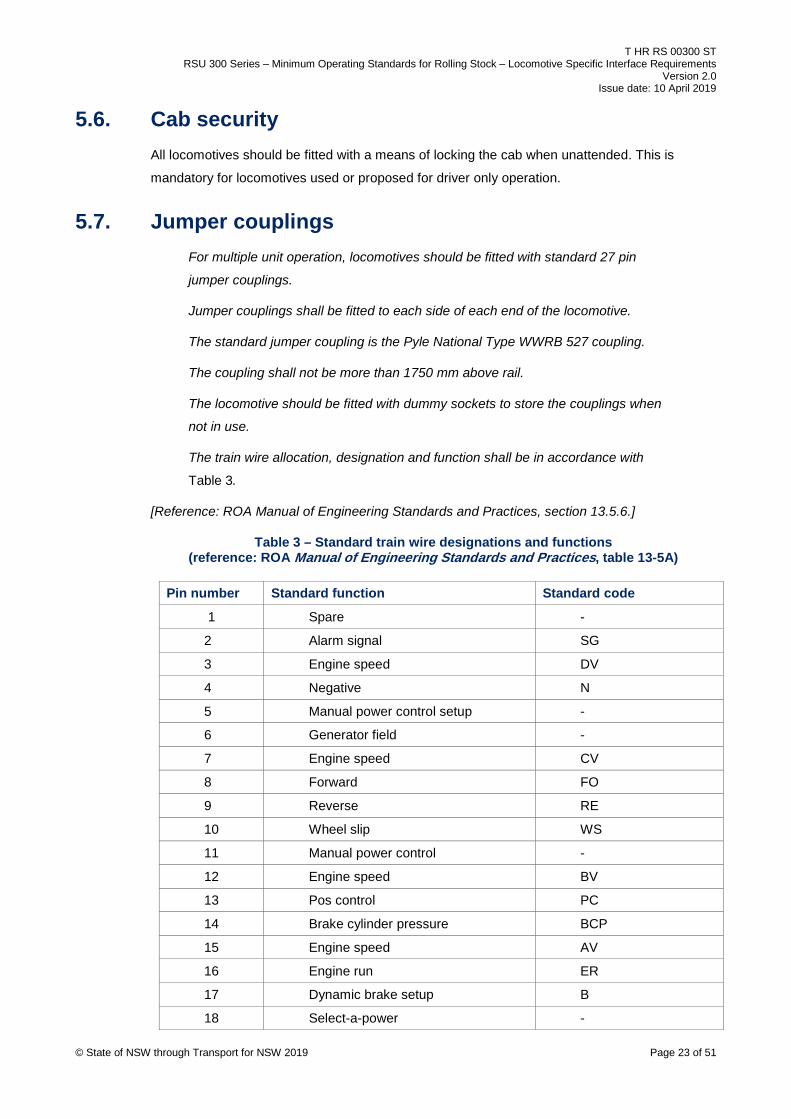
The train wire allocation, designation and function shall be in accordance with
Table 3.
[Reference: ROA Manual of Engineering Standards and Practices, section 13.5.6.]
Table 3 – Standard train wire designations and functions (reference: ROA Manual of Engineering Standards and Practices, table 13-5A)
Pin number Standard function Standard code
1 Spare -
2 Alarm signal SG
3 Engine speed DV
4 Negative N
5 Manual power control setup -
6 Generator field -
7 Engine speed CV
8 Forward FO
9 Reverse RE
10 Wheel slip WS
11 Manual power control -
12 Engine speed BV
13 Pos control PC
14 Brake cylinder pressure BCP
15 Engine speed AV
16 Engine run ER
17 Dynamic brake setup B
18 Select-a-power - © State of NSW through Transport for NSW 2019 Page 23 of 51

T HR RS 00300 ST RSU 300 Series – Minimum Operating Standards for Rolling Stock – Locomotive Specific Interface Requirements
Version 2.0 Issue date: 10 April 2019
Pin number Standard function Standard code
19 Spare -
20 Brake warning light BW
21 Dynamic brake BG
22 Compressor CC
23 Sanding SA
24 Brake control – dynamic brake excitation
BC
25 Park brake on -
26 Park brake off -
27 Spare -
5.8. Fire resistance Consideration shall be given to maximise the fire resistance, and limit the flammability and
toxicity properties for materials used in the construction of rolling stock.
All materials used in the construction of locomotives shall be selected to minimise the risk of
fire, the rate of spread and the level and effect of the products on combustion.
The locomotive design and construction shall minimise the potential for a fire to spread rapidly
throughout the vehicle, into the roof space, or to adjoining vehicles or buildings and structures.
© State of NSW through Transport for NSW 2019 Page 24 of 51

T HR RS 00300 ST RSU 300 Series – Minimum Operating Standards for Rolling Stock – Locomotive Specific Interface Requirements
Version 2.0 Issue date: 10 April 2019
6. Vehicle performance – RSU 340 The performance specified in this section relates to the operation of the locomotive on the
TfNSW Metropolitan Heavy Rail Network. This section covers compatibility tests, adhesion and
structural strength tests.
6.1. Test requirement summary Table 4 summarises the test requirements for locomotives.
Table 4 – Locomotives test requirements
Compatibility test References in other standards
References in this standard
Static rolling stock outline test T HR RS 00200 ST (RSU 281)
-
Static vehicle weigh test T HR RS 00200 ST (RSU 282)
Section 6.5 (RSU 340)
Static vehicle twist test T HR RS 00200 ST (RSU 283)
-
Vehicle/bogie swing test T HR RS 00200 ST (RSU 284)
-
Vehicle/vehicle swing test T HR RS 00200 ST (RSU 285)
-
Static brake test T HR RS 00200 ST (RSU 286)
Section 8, (RSU 342)
Signal visibility test T HR RS 00200 ST (RSU 293)
-
Electrical safety inspection T HR RS 00200 ST (RSU 294)
-
Safety equipment function test T HR RS 00200 ST (RSU 299)
Brake performance test T HR RS 00200 ST (RSU 287)
Section 8, (RSU 342) Refer to Note 1 below
Ride performance test T HR RS 00200 ST (RSU 288)
Section 9, (RSU 343) Refer to Note 1 below
Kinematic rolling stock outline test
T HR RS 00200 ST (RSU 289)
Refer to Note 1 below
Traction performance test - Section 7, (RSU 341) Refer to Note 1 below
Environmental test T HR RS 00100 ST (RSU 292)
Refer to Note 1 below
Signal interference test T HR RS 00200 ST (RSU 295)
Refer to Note 1 below
Signal interference test T HR RS 00200 ST (RSU 296)
Refer to Note 1 below
© State of NSW through Transport for NSW 2019 Page 25 of 51

T HR RS 00300 ST RSU 300 Series – Minimum Operating Standards for Rolling Stock – Locomotive Specific Interface Requirements
Version 2.0 Issue date: 10 April 2019
Compatibility test References in other standards
References in this standard
Fitment of AEI tags T HR RS 00880 ST (RSU App H)
Section 5.5, (RSU 330)
Fitment of reflective delineators
T HR RS 00890 ST (RSU App I)
Section 5.5, (RSU 330)
Note 1: Refer to T HR RS 00200 ST (RSU 280) for sequencing of tests, and the
requirements for movement of vehicles and for conducting dynamic tests.
6.2. Jacking point vertical load test The owner or operator should conduct jacking point vertical load tests to ensure that the
locomotive is capable of withstanding loads imposed during vehicle recovery.
Refer to T HR RS 00200 ST (RSU 297).
6.3. Static end compression test The owner or operator should conduct a static end compression test to ensure that the
locomotive is capable of withstanding the loads imposed during operation.
If a static end compression test is conducted, then loads shall be commensurate with the
proposed maximum duty of the vehicle.
Refer to T HR RS 00200 ST (RSU 297).
6.4. Single vehicle impact The owner or operator should conduct single vehicle impact tests to ensure that the locomotive
is capable of withstanding the loads imposed during operation.
Refer to T HR RS 00200 ST (RSU 297).
6.5. P2 force determination and P/D ratio The P2 force and P/D ratio shall not exceed the limits specified in T HR RS 00100 ST (RSU
120).
6.6. Locomotive weigh test, mass and axle loads Locomotives shall be type tested to determine the fully provisioned mass, however, where any
axle load can possibly exceed agreed limits, each locomotive of that type shall be weighed to
determine the load distribution across all axles.
For maximum adhesive tractive effort, it is in the interest of owners and operators to have their
locomotive axle load distribution for each individual locomotive on driven axles within the limits
specified in T HR RS 00200 ST (RSU 282). The static weigh test is a mandatory requirement. © State of NSW through Transport for NSW 2019 Page 26 of 51

T HR RS 00300 ST RSU 300 Series – Minimum Operating Standards for Rolling Stock – Locomotive Specific Interface Requirements
Version 2.0 Issue date: 10 April 2019
The maximum locomotive mass for unrestricted main line operation on the TfNSW Metropolitan
Heavy Rail Network (main lines) is 134 tonnes for a 6 axle locomotive (22.33 tonne axle load),
subject to the bridge loading requirements.
Locomotives shall be reviewed to determine their bridge loading. Refer to T HR RS 00100 ST
(RSU 120) for further details. The locomotive mass and wheel spacing shall be such that the
bridge loading shall not exceed the specified limits.
© State of NSW through Transport for NSW 2019 Page 27 of 51
T HR RS 00300 ST RSU 300 Series – Minimum Operating Standards for Rolling Stock – Locomotive Specific Interface Requirements
Version 2.0 Issue date: 10 April 2019
7. Traction performance – RSU 341 Traction performance tests shall be carried out for each type of locomotive to determine the
loads that the locomotive can be expected to haul reliably, and to ensure that the locomotive
can haul its rated load in all weather conditions without causing damage to the railhead.
7.1. Introduction The traction performance test shall be undertaken in line with T HR RS 40001 PR Testing of
Locomotive All-Weather Adhesion Performance.
The test locomotive shall have minimum fuel, but have sufficient fuel to complete the nominated
journey to a Sydney location.
The fuel level shall be recorded before conducting traction performance tests.
An adhesion test shall be carried out with a single test locomotive. Additional tests may be
carried out with multiple test locomotives.
Following the completion of the traction performance test and adhesion test, the agreed
locomotive loads and conditions for operation on the TfNSW Metropolitan Heavy Rail Network
will be published in TS TOC 1 Train Operating Conditions (TOC) manual – General Instructions.
7.2. Sanding Locomotives may use sand to enhance the adhesion capabilities in poor conditions.
Locomotives equipped with sanding equipment for adhesion enhancement shall have adequate
measures in place to prevent sand leakage and abnormal sanding.
Sanding systems shall have a means for preventing water ingress into the sanding system
(boxes, traps and pipes) and eliminate sand box and pipe blockage.
Locomotives using sand shall be equipped with an approved system for removing
sand from the rails immediately behind the last wheel of the trailing bogie, in each
direction of travel. The system shall be controlled by and operate concurrently with
the sand application system.
[Reference: ROA Manual of Engineering Standards and Practices, section 13.11.5.3.]
7.3. Wheelslip control All locomotives operating on the TfNSW Metropolitan Heavy Rail Network shall be fitted with a
suitable wheelslip control system to prevent uncontrolled wheelslip. Heritage locomotives that
do not comply with this requirement will be considered on a case-by-case basis.
© State of NSW through Transport for NSW 2019 Page 28 of 51
T HR RS 00300 ST RSU 300 Series – Minimum Operating Standards for Rolling Stock – Locomotive Specific Interface Requirements
Version 2.0 Issue date: 10 April 2019
All locomotives operating on the TfNSW Metropolitan Heavy Rail Network shall be fitted with a
wheelslip detection system which shall be train lined to ensure that wheelslip on other
locomotives in a multiple unit consist is capable of being monitored by the driver of the consist.
7.4. Locomotive configuration – traction control software The configuration of the locomotive shall be as intended for operation within the TfNSW
Metropolitan Heavy Rail Network. The version of any traction control software fitted shall be
specified by the owner or operator.
If any amendment or version upgrade is implemented, the locomotive owner shall advise the
ASA and provide evidence with supporting documentation that traction performance and signal
interference will not be affected by the change. The ASA may require further testing of the
traction performance or signal interference to confirm the changes.
7.5. Wheel creep Most modern locomotives obtain an enhanced adhesion level by permitting some wheel creep.
However, as excessive wheel creep may damage, or accelerate the wear of the railhead, it is
important that wheel creep be limited.
The maximum permitted locomotive wheel creep shall not exceed the following values:
• locomotive speeds between 0 km/h and 5 km/h – 10% maximum creep
• locomotive speeds above 5 km/h – 6% maximum creep
Locomotive owners or operators shall submit data specifying the maximum and average wheel
creep.
7.6. Dynamic brake performance During dynamic braking, the maximum braking force that a locomotive exerts shall not exceed
the following limits:
• locomotive speed between 0 km/h and 16 km/h – linearly from 0 kN (at 0 km/h) to 230 kN
(at 16 km/h)
• locomotive speed above 16 km/h – 230 kN
Owners or operators shall ensure that train crew have clear procedures to maintain this
requirement where not controlled by the locomotive.
7.7. Longitudinal rail force For alternating current (AC) traction locomotives, when three locomotives are marshalled at the
front of the train and are powering there is a risk of track buckling due to compressive reactive
© State of NSW through Transport for NSW 2019 Page 29 of 51

T HR RS 00300 ST RSU 300 Series – Minimum Operating Standards for Rolling Stock – Locomotive Specific Interface Requirements
Version 2.0 Issue date: 10 April 2019
forces in the rail immediately behind the last powering locomotive. To minimise this risk, an
unloaded vehicle or empty platform in the case of intermodal vehicles shall not be marshalled in
this position when the trailing load exceeds 70% of the maximum load (for the locomotive
consist on the train).
For AC traction locomotives, testing shall be conducted to validate the level of longitudinal force
exerted by the locomotive to the rails under maximum tractive effort.
7.8. Traction performance test The ASA reserves the right to undertake practical testing of locomotives to verify their
performance claim.
The decision to undertake such testing will be based upon the following factors:
• previous experience with the locomotives to be introduced (or similar types)
• known problems with the locomotives being introduced (on the TfNSW Metropolitan Heavy
Rail Network or elsewhere)
Any locomotive configuration which has not been previously tested in accordance with T HR RS
40001 PR shall be tested.
7.9. Traction performance test - method Unless otherwise formally advised by the ASA, the location of the traction performance test
shall be between Hawkesbury River and Cowan in the Up direction (Cowan Bank) on the Main
North. Alternative test locations may be possible; however this attracts operational restrictions
for the locomotive. Alternate test locations are only permitted by formal advice from the ASA.
Note: If a load test is undertaken at any location other than the Cowan Bank the
results can only be used to authorise loads for that particular corridor / line. The load
test cannot be used to authorise loads across the TfNSW Metropolitan Heavy Rail
Network.
The process documented in T HR RS 40001 PR shall be followed.
7.10. Traction performance tests – acceptance criteria The following criteria shall be used to assess the tractive performance of locomotives:
a. traction performance - successfully haul specified trailing load with no uncontrolled
wheelslip under all weather conditions (refer to T HR RS 40001 PR for further details)
b. minimum speed – the minimum speed shall not fall below 10 km/h at any time during the
test (refer to T HR RS 40001 PR for further details)
© State of NSW through Transport for NSW 2019 Page 30 of 51
T HR RS 00300 ST RSU 300 Series – Minimum Operating Standards for Rolling Stock – Locomotive Specific Interface Requirements
Version 2.0 Issue date: 10 April 2019
c. locomotive equipment – traction motor currents shall not exceed their short time ratings at
any time during the test (refer to T HR RS 40001 PR for further details)
d. running time – attain a sectional running time that is less than or equal to the published
schedule in TS TOC 2, Train Operation Conditions (TOC) Manual – Division Pages (refer
to T HR RS 40001 PR for further details)
e. maximum wheel creep not to exceed that specified in Section 7.5 of this standard
These criteria shall be clearly met and demonstrated by practical test. Simulation of any part of
the test shall not be accepted. The ASA reserves the right to retest the locomotive where there
is ambiguity or doubt in the locomotive performance, test conditions, or test results.
7.11. Setting maximum load The maximum load a locomotive can haul shall be determined by successful adhesion tests.
Generally, the load and recommended sectional running times will be specified within the load
ratings already published in TS TOC 1 and TS TOC 2, Train Operating Conditions (TOC)
Manual.
7.12. Consultation When a locomotive owner or operator does not agree with the load specified by the ASA, then
the owner or operator shall provide further documentation such as successful operation
elsewhere, enhancements of the locomotives, or evidence of technical failures on the tested
locomotives as part of a case for further review.
Subsequent tests may be done at the cost of the owner or operator.
© State of NSW through Transport for NSW 2019 Page 31 of 51

T HR RS 00300 ST RSU 300 Series – Minimum Operating Standards for Rolling Stock – Locomotive Specific Interface Requirements
Version 2.0 Issue date: 10 April 2019
8. Braking performance – RSU 342 Braking performance is specified to ensure that locomotives are compatible with spacing and
overlaps of the current signalling systems. Refer to T HR RS 00100 ST (RSU 160) for more
information on the signalling interface.
The requirement for locomotive braking is to conduct a static brake test to confirm that the brake
system provides the required level of brake block forces and therefore the expected dynamic
performance is compliant. The static brake test is then followed by a dynamic brake test to
confirm that the braking performance of the locomotive is within the stopping distances required
for the TfNSW Metropolitan Heavy Rail Network.
8.1. Static brake test The static brake tests described in Section 8.1.1 to Section 8.1.4 are required for locomotives.
8.1.1. Static brake valve operation test Static brake valve operation tests shall be conducted to ensure that the brakes apply and
release and that the pressures and timings comply with Section 3 (RSU 320) of this standard.
8.1.2. Brake block force test The minimum net brake ratios detailed in Table 5 are recommended for a full service application
of the automatic brake (brake cylinder pressure 350 kPa). Refer to T HR RS 00200 ST (RSU
286) for more information on brake block force tests.
Table 5 – Locomotive minimum brake ratios for automatic and independent brake
Brake block type Minimum net brake ratio - automatic brake
Minimum net brake ratio - independent brake
High friction composite 13% 20%
Medium friction composite 20% 34%
Low friction composite 28% 45%
Cast iron 28% 45%
Net brake ratios shall be measured with a 150 kPa brake pipe reduction for the automatic brake
and a full application for the independent brake.
8.1.3. Single car air test
A single car air test may be required; refer to Section 8.4 of this standard for more information.
© State of NSW through Transport for NSW 2019 Page 32 of 51

T HR RS 00300 ST RSU 300 Series – Minimum Operating Standards for Rolling Stock – Locomotive Specific Interface Requirements
Version 2.0 Issue date: 10 April 2019
8.1.4. Parking/hand brake holding test The spring parking or handbrakes on locomotives shall be capable of holding the
locomotive in the fully provisioned condition on a 1 in 30 grade indefinitely.
The spring parking brake shall be applied to the maximum number of axles as is feasible.
The status of each spring or manual parking brake shall be indicated in the cab. The
status of the parking brakes shall also be train-lined as indicated in Table 3 (RSU 330) so
that any applied brake or brakes in a locomotive consist are indicated to the driver.
[Reference: ROA Manual of Engineering Standards and Practices, section 13.10.1.2.]
8.2. On track brake performance (light locomotives) Braking performance of a locomotive with high friction composite brake blocks shall comply with
the requirements in this section.
A full service application of the locomotive automatic brake (350 kPa brake cylinder pressure,
150 kPa brake pipe reduction) shall be able to stop the locomotive on level tangent track, with
dry rails, within the stopping distances specified in Table 6.
Table 6 – Minimum brake stopping distance with high friction brake blocks [Reference: ROA Manual of Engineering Standards and Practices, section 13.10.1.1]
Speed (km/h) Stopping distance (metres)
20 50
40 150
60 250
80 400
100 600
120 800 (extrapolated)
140 1050 (extrapolated)
Braking performance of locomotives with low friction composite brake blocks, medium friction
composite brake blocks, or cast iron brake blocks, with a full service application of the
locomotive automatic brake (350 kPa brake cylinder pressure, 150 kPa brake pipe reduction),
shall be able to stop the locomotive within the stopping distances specified in Table 7.
Braking performance of other types of rolling stock are outlined in T HR RS 00830 ST RSU
Appendix C - Brake Performance Curves.
© State of NSW through Transport for NSW 2019 Page 33 of 51

T HR RS 00300 ST RSU 300 Series – Minimum Operating Standards for Rolling Stock – Locomotive Specific Interface Requirements
Version 2.0 Issue date: 10 April 2019
Table 7 – Minimum brake stopping distance (brake blocks other than high friction)
Speed (km/h) Stopping distance (metres)
20 94
40 281
60 523
80 836
100 1229
115 1587
Note: The stopping distances in Table 7 are aligned with the GW16 brake
performance curve in T HR RS 00830 ST.
8.3. Operation of driver safety systems The driver safety systems are generally interfaced to the automatic brake system (driver safety
system penalties vent the brake pipe to atmosphere). Therefore the on track brake performance
shall be associated with the automatic brake performance. Independent brake is not accepted,
as this performance is not associated with the driver safety systems.
Refer to Section 10 (RSU 350) of this standard for operation of the driver safety systems.
8.4. Locomotives to be hauled dead attached Locomotives that are to be hauled dead attached on the rear of a train or within a train consist
but not marshalled against the train locomotives shall be single car tested for sensitivity of the
brake equipment. Refer to T HR RS 00200 ST (RSU 286) for more information.
© State of NSW through Transport for NSW 2019 Page 34 of 51
T HR RS 00300 ST RSU 300 Series – Minimum Operating Standards for Rolling Stock – Locomotive Specific Interface Requirements
Version 2.0 Issue date: 10 April 2019
9. Locomotive ride performance – RSU 343 The minimum bogie related performance requirements for the operation of locomotives on the
TfNSW Metropolitan Heavy Rail Network are provided in Section 9.1 to Section 9.3.
9.1. Base ride performance requirements For freight vehicles, the base ride performance requirements are as specified in
T HR RS 00200 ST (RSU 288).
For locomotives equipped with vibration isolated cabs, the base ride performance specified shall
be measured using accelerometers positioned outside the cab, but as near as possible to the
locomotive trailing bogie centre.
Sustained hunting is not permitted. In this case, hunting shall be defined as sinusoidal lateral
oscillations of the wheelset resulting in greater than 0.5 Hz sinusoidal lateral body accelerations
measured at the bogie centre of greater than 0.15 g sustained for 10 seconds or longer.
If the vehicle is fitted with an isolated cab, hunting shall be assessed using a lateral
accelerometer positioned on the underframe outside the cab, as near as possible to the trailing
bogie centre.
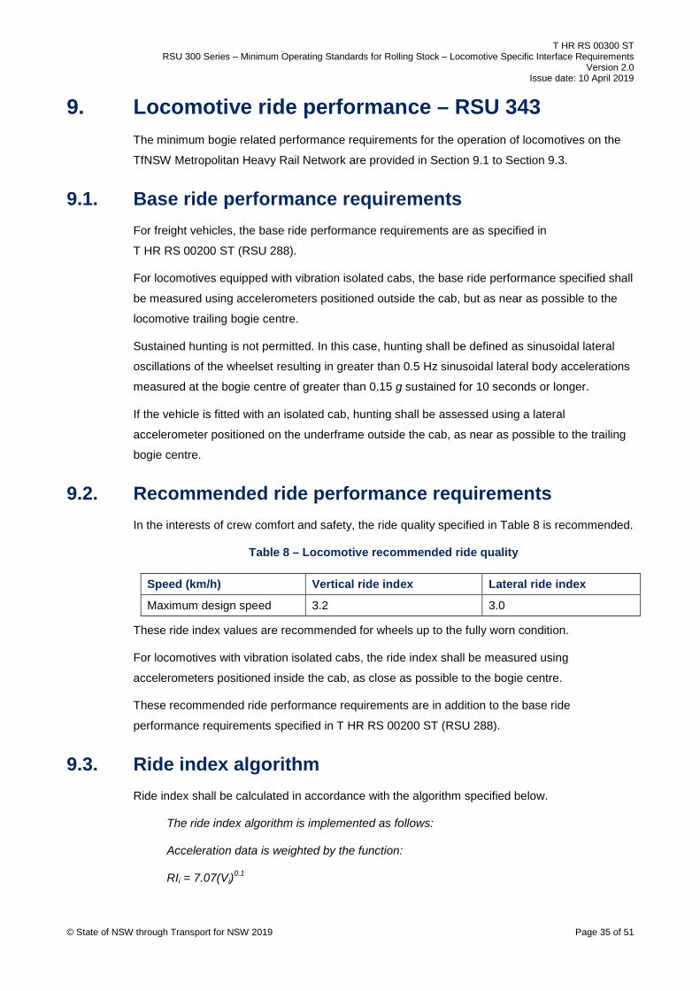
9.2. Recommended ride performance requirements In the interests of crew comfort and safety, the ride quality specified in Table 8 is recommended.
Table 8 – Locomotive recommended ride quality
Speed (km/h) Vertical ride index Lateral ride index
Maximum design speed 3.2 3.0
These ride index values are recommended for wheels up to the fully worn condition.
For locomotives with vibration isolated cabs, the ride index shall be measured using
accelerometers positioned inside the cab, as close as possible to the bogie centre.
These recommended ride performance requirements are in addition to the base ride
performance requirements specified in T HR RS 00200 ST (RSU 288).
9.3. Ride index algorithm Ride index shall be calculated in accordance with the algorithm specified below.
The ride index algorithm is implemented as follows:
Acceleration data is weighted by the function:
RIi = 7.07(Vi)0.1
© State of NSW through Transport for NSW 2019 Page 35 of 51

T HR RS 00300 ST RSU 300 Series – Minimum Operating Standards for Rolling Stock – Locomotive Specific Interface Requirements
Version 2.0 Issue date: 10 April 2019
Where the i-th value refers to the peak amplitude of a frequency component
derived from a fast fourier transfer (FFT) analyser.
The function Vi is defined as shown in Table 9:
Table 9 – Ride index Vi function
Frequency range (Hz) Vi (vertical) Vi (lateral)
0 – 6 0.32 f.a3 4.32 a3
6 – 20 400 a3/f3 650 a3/f3
20 + a3/f a3/f
Where f = frequency, (Hz), a = amplitude, g peak (1 g = 9.81 m/s2)
The total ride index is calculated from the i values by:
𝑹𝑹𝑹𝑹𝑻𝑻𝑻𝑻𝑻𝑻𝑻𝑻𝑻𝑻 = [∑ (𝑹𝑹𝑹𝑹𝒊𝒊)𝟏𝟏𝟏𝟏𝒊𝒊=𝒏𝒏𝒊𝒊=𝟏𝟏 ]𝟏𝟏.𝟏𝟏
Notes:
• frequency analysis will use FFT analysis of at least 400 lines with 0.25 Hz
resolution. Data shall be averaged over 32 averages to minimise statistical
error. 16 averages is acceptable for comparative evaluations only
• analysis shall be restricted to the 0.5 Hz to 50 Hz band
• weighting filters implementing the above weightings are acceptable provided:
o integration is performed over 10 s to 15 s periods
o the integrated values are recorded over at least 3 km of track and reported as a
mean and sample variance
• data for analysis shall come from samples at substantially constant speed (variance
± 5 km/h)
[Reference: ROA Manual of Engineering Standards and Practices, section 13.4.2]
© State of NSW through Transport for NSW 2019 Page 36 of 51

T HR RS 00300 ST RSU 300 Series – Minimum Operating Standards for Rolling Stock – Locomotive Specific Interface Requirements
Version 2.0 Issue date: 10 April 2019
10. Safety equipment – RSU 350 Requirements for safety equipment involve driver safety systems, speed indicating device, data
logger or recorder, drivers emergency cock, flowmeter, emergency equipment, communications,
lights, and horn.
10.1. Driver safety systems Each locomotive shall be fitted with driver’s safety systems as specified in T HR RS 00840 ST
RSU Appendix D - Train (Driver) Safety Systems, with the following exceptions:
• Some locomotives, for example shunting locomotives and shunting tractors that are
confined to shunting yards, may be exempt from this requirement for shunting use only.
Where such a locomotive is used on a train or travel light engine on the TfNSW
Metropolitan Heavy Rail Network, it shall comply with T HR RS 00840 ST or operate under
special conditions as determined by ASA.
• Steam and heritage locomotives may be exempt from this requirement and operate under
special conditions as determined by ASA.
• Locomotives not fitted with driver’s cabs, for example slave or booster locomotives.
10.2. Speed indicating device Each driving position shall have an operative speed indicating device.
Any speed indicating devices which are displayed on a visual display unit shall display the
speed to an accuracy shown in Table 10 or better, when compared to the true vehicle speed at
all times.
Speedometers should be recalibrated to compensate for wheel wear and wheel turning.
If the speedometer does not have wheel diameter compensation, the speedometer should be
calibrated to a diameter midway between the new wheel diameter and condemning diameter.
Table 10 – Accuracy of speedometers
Type of speedometer Existing vehicles New vehicles from 1 March 2011
Speedometers with wheel diameter compensation
± 7% ± 5%
Speedometers without wheel diameter compensation
± 10% ± 7%
Verification of the speed indicating devices compared to the true vehicle speed shall be
measured by suitably accurate equipment. Verification shall be carried out at 10 km/h intervals
up to the maximum design speed.
© State of NSW through Transport for NSW 2019 Page 37 of 51

T HR RS 00300 ST RSU 300 Series – Minimum Operating Standards for Rolling Stock – Locomotive Specific Interface Requirements
Version 2.0 Issue date: 10 April 2019
10.3. Data logger or recorder Each locomotive shall be fitted with a functioning, reliable and accurate data recording or
logging system.
The system shall meet the requirements of the Office of the National Rail Safety Regulator
(ONRSR) Rail Safety Compliance Code Data Loggers. This guidance material was authored by
the Independent Transport Safety Regulator and is available on the ONRSR website at:
www.onrsr.com.au
The system shall record the information nominated in the ONRSR Rail Safety Compliance Code
Data Loggers.
Some locomotives, for example, shunting locomotives and shunting tractors, which are confined
to shunting yards, may be exempt from this requirement for shunting use only. Where such a
locomotive is used on a train or travel light engine on the TfNSW Metropolitan Heavy Rail
Network it shall comply with the requirements stated in this section.
10.4. Drivers emergency cock Locomotives shall be fitted with an emergency cock or fail-safe emergency brake pipe dump
control near each driving position. The cock when opened shall directly vent the brake pipe to
atmosphere.
10.5. Flowmeter Locomotives shall have a means of indicating both audibly and visually, that air is being fed to
the brake pipe.
10.6. Emergency equipment Each locomotive shall be supplied with the emergency equipment as specified in TS TOC 1
Train Operating Conditions (TOC) Manual – General Instructions, Section 3.11 Emergency
equipment.
Some locomotives, for example shunting locomotives and shunting tractors that are confined to
shunting yards, may be exempt from this requirement for shunting use only. Where such a
locomotive may possibly be used on a train or travel light engine on the TfNSW Metropolitan
Heavy Rail Network it shall comply with the requirements stated in this section.
10.7. Communications Locomotives shall be fitted with a train radio system. Radio frequencies shall be approved by
the ASA. Refer to T HR RS 00100 ST (RSU 190).
© State of NSW through Transport for NSW 2019 Page 38 of 51

T HR RS 00300 ST RSU 300 Series – Minimum Operating Standards for Rolling Stock – Locomotive Specific Interface Requirements
Version 2.0 Issue date: 10 April 2019
Some locomotives, for example, shunting locomotives and shunting tractors that are confined to
shunting yards, may be exempt from this requirement for shunting use only. Where such a
locomotive is used on a train or travel light engine on the TfNSW Metropolitan Heavy Rail
Network it shall comply with the requirements stated in this section.
10.8. Lights Requirements for lights involve headlights, marker lights, tail lights, visibility lights, and
maintenance.
10.8.1. Headlights
Each locomotive shall be fitted with white headlights at any leading end, with details as follows:
• headlight arrangement shall produce a peak intensity of at least 200,000 cd
• the peak intensity requirement shall also be met if devices to protect or diffuse the
headlights are fitted while in service
• the centreline of each headlamp beam should be aimed at a point at centre of track level at
least 240 m ahead and in front of the headlight
• headlights should be at least 2.3 m above rail
• headlights shall have the ability to be dimmed to a low beam setting
• the headlight low beam shall produce a peak intensity of no greater than 80,000 cd
• the headlight arrangement shall be inspected and maintained such that the illumination and
alignment requirements are ensured
10.8.2. Marker lights or tail lights Each locomotive shall be fitted with marker lights or tail lights, with details as follows:
• a pair of red marker lights or tail lights fitted at any trailing end
• a pair of white marker lights fitted at any leading end
• the marker lights or tail lights fitted as high and wide as practical (up to a maximum height
of 3580 mm above rail level), on both sides of each end
• each marker light or tail light shall have a luminous intensity of at least 75 cd
10.8.3. Visibility lights Each locomotive shall be fitted with high visibility ditch lights (fog lights), with details as follows:
• two white visibility lights fitted at any leading end
• each visibility light shall produce a peak intensity of at least 20,000 cd © State of NSW through Transport for NSW 2019 Page 39 of 51

T HR RS 00300 ST RSU 300 Series – Minimum Operating Standards for Rolling Stock – Locomotive Specific Interface Requirements
Version 2.0 Issue date: 10 April 2019
• visibility lights shall be at least 600 mm above the top of the rail
• visibility lights should be no more than 1200 mm above the top of the rail
• visibility lights shall be laterally separated by at least 900 mm if they are mounted at least
1500 mm below the headlights
• visibility lights shall be laterally separated by at least 1500 mm if they are mounted less
than 1500 mm below the headlights
• visibility lights shall be aimed at a point that is at least 25 metres in front of the locomotive
at top of rail
• visibility lights shall then be aimed or turned cross-eyed to between a minimum of
7.5 degrees and a maximum of 15 degrees to the longitudinal centreline of the vehicle
25 metres
7.5 – 15 degrees
7.5 – 15 degrees
Rail level
Figure 1 – Top and side view for visibility light aim requirements
• visibility lights shall alternately flash on and off (at the leading end) when the horn is
sounded or when the locomotive changes direction
• the rate of alternate flashing shall be at least 40 flashes per minute and shall be at a
maximum of 180 flashes per minute
• the flashing shall continue for a period of at least 15 s
Some earlier designs of locomotives may not fully comply with, or may be exempt from, these
requirements. In such cases, the design will be assessed considering the equipment fitted and
the proposed use of the locomotives.
© State of NSW through Transport for NSW 2019 Page 40 of 51
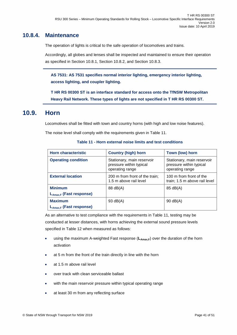
T HR RS 00300 ST RSU 300 Series – Minimum Operating Standards for Rolling Stock – Locomotive Specific Interface Requirements
Version 2.0 Issue date: 10 April 2019
10.8.4. Maintenance The operation of lights is critical to the safe operation of locomotives and trains.
Accordingly, all globes and lenses shall be inspected and maintained to ensure their operation
as specified in Section 10.8.1, Section 10.8.2, and Section 10.8.3.
AS 7531: AS 7531 specifies normal interior lighting, emergency interior lighting, access lighting, and coupler lighting.
T HR RS 00300 ST is an interface standard for access onto the TfNSW Metropolitan Heavy Rail Network. These types of lights are not specified in T HR RS 00300 ST.
10.9. Horn Locomotives shall be fitted with town and country horns (with high and low noise features).
The noise level shall comply with the requirements given in Table 11.
Table 11 - Horn external noise limits and test conditions
Horn characteristic Country (high) horn Town (low) horn
Operating condition Stationary, main reservoir pressure within typical operating range
Stationary, main reservoir pressure within typical operating range
External location 200 m from front of the train; 1.5 m above rail level
100 m from front of the train; 1.5 m above rail level
Minimum LAmax,F (Fast response)
88 dB(A) 85 dB(A)
Maximum LAmax,F (Fast response)
93 dB(A) 90 dB(A)
As an alternative to test compliance with the requirements in Table 11, testing may be
conducted at lesser distances, with horns achieving the external sound pressure levels
specified in Table 12 when measured as follows:
• using the maximum A-weighted Fast response (LAmax,F) over the duration of the horn
activation
• at 5 m from the front of the train directly in line with the horn
• at 1.5 m above rail level
• over track with clean serviceable ballast
• with the main reservoir pressure within typical operating range
• at least 30 m from any reflecting surface
© State of NSW through Transport for NSW 2019 Page 41 of 51

T HR RS 00300 ST RSU 300 Series – Minimum Operating Standards for Rolling Stock – Locomotive Specific Interface Requirements
Version 2.0 Issue date: 10 April 2019
Table 12 - Horn external noise limits – alternative testing at lower distances
Horn characteristic Country horn (Note a) Town horn (Note b)
Operating conditions Stationary, main reservoir pressure within typical operating range
Stationary, main reservoir pressure within typical operating range
External location 5 m from front of the train; 1.5 m above rail level
5 m from front of the train; 1.5 m above rail level
Minimum LAmax,F (Fast response)
124 dB(A) 114 dB(A)
Maximum LAmax,F (Fast response)
129 dB(A) 119 dB(A)
Notes:
a. Only valid for a country horn with a fundamental frequency in the range 390 Hz ±
25 Hz.
b. Only valid for a town horn with a fundamental frequency in the range 290 Hz ±
25 Hz.
© State of NSW through Transport for NSW 2019 Page 42 of 51

T HR RS 00300 ST RSU 300 Series – Minimum Operating Standards for Rolling Stock – Locomotive Specific Interface Requirements
Version 2.0 Issue date: 10 April 2019
11. Locomotive type specific requirements – RSU 360 Specific requirements for the following types of locomotives and types of operations are listed in
Section 12 to 17:
• diesel electric and diesel hydraulic (RSU 361)
• electric (RSU 362)
• steam (RSU 363)
• driver only operation (RSU 364)
• remote controlled (RSU 365)
• high-speed passenger (RSU 366)
12. Diesel electric and diesel hydraulic locomotives – RSU 361 All diesel electric and diesel hydraulic locomotives shall comply with the requirements contained
in Section 1 to Section 10 (RSU 300 to RSU 350) of this standard.
12.1. Hauling a dead diesel or hydraulic locomotive The operator or owner shall have procedures for hauling a diesel or hydraulic locomotive dead.
These procedures shall specify under what conditions the Cardan shaft needs to be removed
and allowable maximum speeds.
12.2. Spark arresters All diesels shall be fitted with spark emission control devices (spark arresters) in accordance
with AS 1019 Internal Combustion Engines – Spark Emission Control Devices.
Note: Refer to section 9 of AS 1019, for exhaust systems and turbochargers that are
deemed to comply as spark emission control devices.
© State of NSW through Transport for NSW 2019 Page 43 of 51

T HR RS 00300 ST RSU 300 Series – Minimum Operating Standards for Rolling Stock – Locomotive Specific Interface Requirements
Version 2.0 Issue date: 10 April 2019
13. Electric locomotives – RSU 362 All electric locomotives shall comply with the requirements contained in Section 1 to Section 10
(RSU 300 to RSU 350) of this standard.
This section covers additional specific requirements relating to electric locomotives.
Refer to T HR RS 00100 ST (RSU 130) for pantograph and overhead wire interface
requirements.
13.1. Pantograph isolation Where two pantographs on a locomotive are electrically connected, a pantograph isolating
switch shall be fitted to allow electrical separation of the two pantographs.
13.2. Use of multiple pantographs Restrictions apply to the number of pantographs that are permitted to be simultaneously raised
on locomotives when operating on the TfNSW Metropolitan Heavy Rail Network. These
restrictions are specified in TS TOC 1 Train Operating Conditions (TOC) Manual – General
Instructions, and are found in the notes associated with the accepted electric locomotives.
13.3. Energy consumption meter For commercial operations, ASA may require owners or operators to fit energy consumption
meters to their electric locomotives.
© State of NSW through Transport for NSW 2019 Page 44 of 51

T HR RS 00300 ST RSU 300 Series – Minimum Operating Standards for Rolling Stock – Locomotive Specific Interface Requirements
Version 2.0 Issue date: 10 April 2019
14. Steam locomotives – RSU 363 All steam locomotives shall comply with the requirements contained in Section 1 to Section 10
(RSU 300 to RSU 350) of this standard.
This section covers additional specific requirements relating to steam locomotives.
14.1. Boiler inspections Each steam locomotive shall have a boiler inspection in accordance with the requirements of
SafeWork NSW (formerly WorkCover NSW) and the relevant Australian standards.
14.2. Flangeless wheels There is a risk of flangeless wheels striking raised check rails on the TfNSW Metropolitan Heavy
Rail Network. Details of flangeless wheels and associated information (such as bogie to body
arrangement, wheel spacing, and wheelset clearances within bogies) shall be provided to ASA
for assessment.
14.3. Firebox servicing Owner and operators shall not discharge the firebox or ash pan onto the track when in the
TfNSW Metropolitan Heavy Rail Network.
14.4. Bushfire danger Steam locomotives shall be fitted with spark arresters. Operation of steam locomotives may be
suspended during bushfire danger periods.
© State of NSW through Transport for NSW 2019 Page 45 of 51

T HR RS 00300 ST RSU 300 Series – Minimum Operating Standards for Rolling Stock – Locomotive Specific Interface Requirements
Version 2.0 Issue date: 10 April 2019
15. Driver only operation – RSU 364 This section covers specific requirements relating to locomotives used in driver only operation.
15.1. Additional equipment Lead locomotives of a driver only operated train shall comply with the following:
• be fitted with a pressure maintaining brake valve
• be fitted with working ‘onboard’ communications equipment which provides direct
communications with the Train Control Centre
• have reduced vigilance control system timings in accordance with Table 1 in T HR RS
00840 ST (RSU Appendix D)
• have a second driver’s safety system, refer to T HR RS 00840 ST (RSU Appendix D)
• not be operated with long end leading in the case of single cab locomotives
• be fitted with door locks to prevent illegal entry of cab while locomotive is unattended
• carry a dump valve clamp (DVC) in the lead locomotive
15.2. Acceptance ASA approval shall be obtained before operating in a driver only train.
© State of NSW through Transport for NSW 2019 Page 46 of 51

T HR RS 00300 ST RSU 300 Series – Minimum Operating Standards for Rolling Stock – Locomotive Specific Interface Requirements
Version 2.0 Issue date: 10 April 2019
16. Remote controlled locomotives – RSU 365 This section covers specific requirements relating to locomotives being operated by remote
control from another locomotive. This method of control is usually referred to as wired
distributed power or radio frequency distributed power.
16.1. Introduction Remote controlled locomotives may be marshalled within a train consist or at the rear of the
train consist.
The remote locomotive can be controlled from the leading locomotive of a train through hard
wiring (wired distributed power – WDP) or by radio signal (radio frequency distributed power –
RFDP).
Mixing of remote control equipped locomotives and standard (non-equipped remote control)
locomotives is not permitted unless under recovery conditions with specific procedures for
control of brakes and traction and relevant network rules.
All WDP and RFDP operations shall be accepted by ASA prior to operation. All accepted
operations shall be published in TS TOC 1 Train Operating Conditions (TOC) Manual – General
Instructions. Refer to section 2.4 of TS TOC 1 for information on distributed power.
16.2. Wired distributed power A WDP system uses the system hardware associated with the ECP brake system.
A locomotive (both lead controlling, and remote controlled) using WDP shall meet the
requirements associated with ECP brake system requirements in Section 3.8 of this standard.
In addition to the requirements of Section 3.8, the locomotives shall meet the requirements in
AAR Manual of Standards and Recommended Practices, section E-II, S 4250.
Any freight vehicles within the WDP train shall also be required to meet the ECP brake system
requirements given in T HR RS 00400 ST RSU 400 Series - Freight Vehicle Specific Interface
Requirements. Refer to T HR RS 00400 ST (RSU 420) for further information on these
requirements.
The WDP system on the locomotives shall be compatible with the ECP system used on the
freight vehicles and the WDP system used on the other locomotives.
WDP functionality shall be tested for correct operation on all train configurations for which it is
intended to operate.
A risk register and risk assurance report shall be generated to determine the risks associated
with WDP operations on the TfNSW Metropolitan Heavy Rail Network and ensure the WDP
© State of NSW through Transport for NSW 2019 Page 47 of 51
T HR RS 00300 ST RSU 300 Series – Minimum Operating Standards for Rolling Stock – Locomotive Specific Interface Requirements
Version 2.0 Issue date: 10 April 2019
operation is as safe SFAIRP. The register and report shall be submitted to ASA for confirmation
and acceptance prior to WDP operation.
16.3. Radio frequency distributed power Any operation with radio control equipment for radio frequency distributed power (RFDP) shall
be accepted by ASA prior to operation on the TfNSW Metropolitan Heavy Rail Network.
17. Locomotives for high-speed passenger service – RSU 366 This section covers specific requirements relating to locomotives operating as dedicated high-
speed passenger locomotives.
While compliance with Section 2 to Section 16 would suffice in meeting the performance at a
locomotive level, it is unlikely to be sufficient in meeting the final performance on track for a high
speed passenger service described in this section.
Requirements in Section 17 take priority if there are any conflicts with requirements specified in
Section 2 to Section 16.
17.1. Designation of high-speed passenger locomotives Locomotives are defined as high-speed passenger locomotives when all the following operating
conditions apply:
• operate dedicated passenger only service (no freight operation)
• operate at speeds above 115 km/h
• operate to medium, high, or XPT speed boards
Note: These types of locomotives commonly operate in a push-pull configuration, coupled semi-
permanently with dedicated high-speed non-powered (trailer) passenger vehicles.
17.2. Applicable requirements Section 17.2.1 to Section 17.2.10 provides clarification on the applicable standards for
locomotives designated as high-speed passenger locomotives.
17.2.1. Braking systems The braking system shall meet the requirements of RSU 620 of T HR RS 00600 ST RSU 600
Series - Multiple Unit Train Specific Interface Requirements. The braking system requirements
detailed in T HR RS 00300 ST (RSU 320) are not mandatory in this particular case as it may
restrict the locomotive meeting the requirements in T HR RS 00600 ST (RSU 620).
© State of NSW through Transport for NSW 2019 Page 48 of 51
T HR RS 00300 ST RSU 300 Series – Minimum Operating Standards for Rolling Stock – Locomotive Specific Interface Requirements
Version 2.0 Issue date: 10 April 2019
17.2.2. Braking performance When the locomotive or locomotives are in their normal operating consist with dedicated high-
speed passenger cars, the braking performance shall meet the requirements of
T HR RS 00600 ST (RSU 641). That is, braking performance requirements detailed in
T HR RS 00300 ST (RSU 342) shall not apply.
Where the consists may vary, the consist with the worst braking performance shall be assessed.
For high-speed passenger locomotives operating on their own or in a light locomotive consist,
the brake performance detailed in T HR RS 00300 ST (RSU 342) shall apply.
17.2.3. Braking performance – dynamic brake Refer to T HR RS 00300 ST (RSU 321) for dynamic brake requirements. In addition, the
dynamic brake system shall account for continuous operation on all terrain and conditions found
in the networks on which the locomotive will operate. This applies to diesel locomotives, electric
locomotives, or multi-mode traction locomotives.
For multi-mode traction locomotives, the continuous operation of the dynamic brake shall be
possible in whichever mode or modes the locomotive is operating.
17.2.4. Traction performance In addition to the requirements of T HR RS 00300 ST (RSU 341), the requirements detailed
within T HR RS 00600 ST (RSU 643) shall also apply.
17.2.5. Multi-mode traction If locomotives are equipped with multi-mode traction systems, for example utilising diesel,
onboard electrical power and overhead electrical power, with either a single traction mode
operating at any one time, or multiple traction modes operating at any one time, the locomotive
shall meet the requirements detailed in T HR RS 00600 ST (RSU 680).
17.2.6. Remote locomotives
The system that controls remote locomotives shall ensure that it is not susceptible to
interference from other similar systems on passenger vehicles and systems such as ECP or
WDP, or both on freight vehicles.
The fail-safe design and functionality shall ensure loss of signal events shall be safely
controlled.
Where tractive power is not applied from a leading locomotive, the train's longitudinal and lateral
forces shall be assessed to ensure safe operation across the nominated networks, and their
subsequent curves and grades, with respect to the L/V ratio.
© State of NSW through Transport for NSW 2019 Page 49 of 51

T HR RS 00300 ST RSU 300 Series – Minimum Operating Standards for Rolling Stock – Locomotive Specific Interface Requirements
Version 2.0 Issue date: 10 April 2019
Remote controlled locomotive requirements in T HR RS 00300 ST (RSU 365) are not
mandatory in this particular case as it may restrict the locomotive meeting the requirements in
Section 17.2.6.
17.2.7. Vehicle mechanical, pneumatic and electrical coupling Where non-standard mechanical coupling is utilised, an emergency coupler shall be provided to
allow coupling to standard vehicles and locomotives with AAR 10A contour automatic couplers
(as specified in AAR's Manual of Standards and Recommended Practices).
Where non-standard pneumatic coupling is utilised, emergency coupling hoses shall be
supplied to allow coupling to standard vehicles and locomotives.
Coupler and draft gear requirements, vehicle pneumatic coupling requirements and vehicle
jumper coupling requirements in T HR RS 00300 ST (RSU 320 and RSU 330) are not
mandatory and alternate designs can be utilised.
17.2.8. Signal visiblity The cab design shall provide signal visibility in compliance with T HR RS 00100 ST (RSU 160),
and shall include the signal visibility requirements applicable to EMU and DMU trains.
17.2.9. Body structural integrity and crashworthiness The locomotive shall meet the requirements of T MU RS 01000 ST Structural Integrity and
Crashworthiness of Passenger Rolling Stock.
17.2.10. Applicable standards Table 13 summarises applicable requirements detailed within this standard.
Table 13 – Applicable standards for high-speed passenger locomotives
Applicable standard High-speed passenger locomotives
All other locomotives
T HR RS 00300 ST (RSU 300) Applicable Applicable
T HR RS 00300 ST (RSU 310) Applicable Applicable
T HR RS 00300 ST (RSU 320) Not mandatory, refer to RSU 620 for requirements
Applicable
T HR RS 00300 ST (RSU 321) Applicable Applicable
T HR RS 00300 ST (RSU 330) Applicable Applicable
T HR RS 00300 ST (RSU 340) Applicable Applicable
T HR RS 00300 ST (RSU 341) Applicable Applicable
T HR RS 00300 ST (RSU 342) Not applicable, refer to RSU 642 for requirements
Applicable
T HR RS 00300 ST (RSU 343) Applicable Applicable
© State of NSW through Transport for NSW 2019 Page 50 of 51

T HR RS 00300 ST RSU 300 Series – Minimum Operating Standards for Rolling Stock – Locomotive Specific Interface Requirements
Version 2.0 Issue date: 10 April 2019
Applicable standard High-speed passenger locomotives
All other locomotives
T HR RS 00300 ST (RSU 350) Applicable Applicable
T HR RS 00300 ST (RSU 360) Applicable Applicable
T HR RS 00300 ST (RSU 361) Applicable Applicable
T HR RS 00300 ST (RSU 362) Applicable Applicable
T HR RS 00300 ST (RSU 363) Not applicable Applicable
T HR RS 00300 ST (RSU 364) Applicable Applicable
T HR RS 00300 ST (RSU 365) Applicable, not mandatory Applicable
T HR RS 00300 ST (RSU 366) Applicable Not applicable
© State of NSW through Transport for NSW 2019 Page 51 of 51