t matrix f complete.pdf
TRANSCRIPT
7/27/2019 T MATRIX F COMPLETE.pdf
http://slidepdf.com/reader/full/t-matrix-f-completepdf 1/6
T-MATRIX™F
T o I P N E T W O R K
S O L U T I O N
D E P E N D A B L E T E T R A C O M M U N I C A T I O N
D I S T R I B U T E D I N T E L L I G E N C E
I P R O U T I N G
H I G H F L E X I B I L I T Y
I N D U S T R Y S T A N D A R D C O N N E C T I V I T Y

7/27/2019 T MATRIX F COMPLETE.pdf
http://slidepdf.com/reader/full/t-matrix-f-completepdf 2/6
DispatcherTerminal
Telephony
Gateway
ReferenceDatabase
Automatic VehicleLocation Station
Voice and DataLogging Station (VDLS)
SYSTEM
ENHANCEMENT
PRODUCTS
MANAGEMENT CONTROL CENTRE (MCC)
TETRA
TERMINALS
TETRA
RADIO SITEEQUIPMENT
DirectMode
Voice and
Data Voice andData
GATEWAYS
SDS Gateway
Data Gateway
Network ManagementTerminal
ExternalLAN/WAN
ExternalLAN/WAN
PSTN/PBX
T-MATRIX™ IP
LAN /WAN NETWORK
T-MATRIX™ F is a cost-
effective fixed-site TETRA over
IP (ToIP) communications
solution designed to meet the
needs of professional
organisations requiring a
permanently installed Private
Mobile Radio system.
T-MATRIX™ ToIP solutions are
designed and produced
exclusively by Artevea Digital
Limited (ADL).
T-MATRIX™ site equipment is
scalable according to customer
requirements from 1 to 8
transceivers, providing between
4 and 32 logical channels.
An important distinction
between a TETRA over IP (ToIP)
system and a conventional
(switch-based) TETRA system is
that a ToIP system has no
central switch.
Instead it has distributed
intelligence at each Radio Site
that can process and handle
local calls, set up inter-site calls
and keep track of the
registration locations of each
subscriber, giving an inherently
high resilience to backbone
network faults. It also means
that common resources such as
Dispatchers and Gateways can
be located at any point in the
network.
T-MATRIX™ ToIP systems are
based on dedicated private IP
networks, not the public
Internet. This means they can
be designed according to the
customer’s required Quality of
Service and can also be made
secure.
Additionally, the T-MATRIX™
system achieves a high level of
flexibility through the optimal
use of industry-standard
hardware and software
components in its Network,
Gateway and System
Management equipment.
T-MATRIX™F T o I P N E T W O R K S O L U T I O N
7/27/2019 T MATRIX F COMPLETE.pdf
http://slidepdf.com/reader/full/t-matrix-f-completepdf 3/6
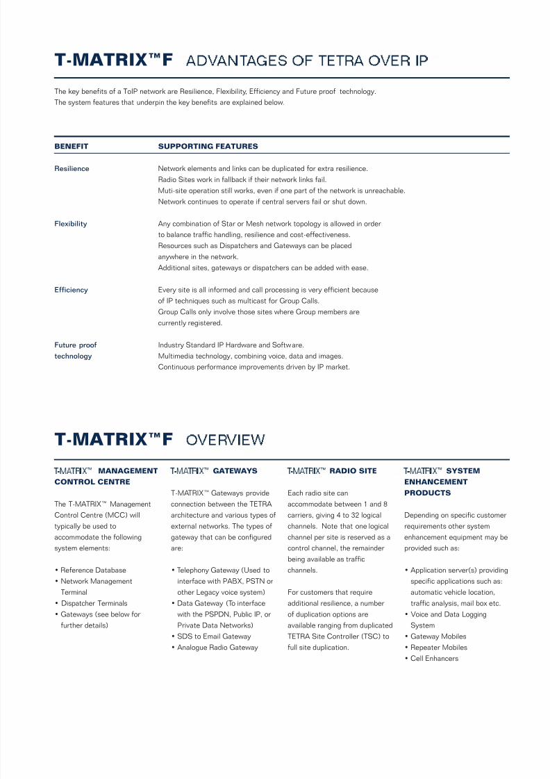
The key benefits of a ToIP network are Resilience, Flexibility, Efficiency and Future proof technology.
The system features that underpin the key benefits are explained below.
BENEFIT SUPPORTING FEATURES
Resilience Network elements and links can be duplicated for extra resilience.
Radio Sites work in fallback if their network links fail.
Muti-site operation still works, even if one part of the network is unreachable.
Network continues to operate if central servers fail or shut down.
Flexibility Any combination of Star or Mesh network topology is allowed in order
to balance traffic handling, resilience and cost-effectiveness.
Resources such as Dispatchers and Gateways can be placed
anywhere in the network.
Additional sites, gateways or dispatchers can be added with ease.
Efficiency Every site is all informed and call processing is very efficient because
of IP techniques such as multicast for Group Calls.
Group Calls only involve those sites where Group members are
currently registered.
Future proof Industry Standard IP Hardware and Software.
technology Multimedia technology, combining voice, data and images.
Continuous performance improvements driven by IP market.
T-MATRIX™F A D V A N T A G E S O F T E T R A O V E R I P
T - M A T R I X ™ MANAGEMENT
CONTROL CENTRE
The T-MATRIX™ Management
Control Centre (MCC) will
typically be used to
accommodate the following
system elements:
• Reference Database
• Network Management
Terminal
• Dispatcher Terminals
• Gateways (see below for
further details)
T - M A T R I X ™ GATEWAYS
T-MATRIX™ Gateways provide
connection between the TETRA
architecture and various types of
external networks. The types of
gateway that can be configured
are:
• Telephony Gateway (Used to
interface with PABX, PSTN or
other Legacy voice system)
• Data Gateway (To interface
with the PSPDN, Public IP, or
Private Data Networks)
• SDS to Email Gateway
• Analogue Radio Gateway
T - M A T R I X ™ RADIO SITE
Each radio site can
accommodate between 1 and 8
carriers, giving 4 to 32 logical
channels. Note that one logical
channel per site is reserved as a
control channel, the remainder
being available as traffic
channels.
For customers that require
additional resilience, a number
of duplication options are
available ranging from duplicated
TETRA Site Controller (TSC) to
full site duplication.
T - M A T R I X ™ SYSTEM
ENHANCEMENT
PRODUCTS
Depending on specific customer
requirements other system
enhancement equipment may be
provided such as:
• Application server(s) providing
specific applications such as:
automatic vehicle location,
traffic analysis, mail box etc.
• Voice and Data Logging
System
• Gateway Mobiles
• Repeater Mobiles
• Cell Enhancers
T-MATRIX™F O V E R V I E W
7/27/2019 T MATRIX F COMPLETE.pdf
http://slidepdf.com/reader/full/t-matrix-f-completepdf 4/6
T-MATRIX™F S Y S T E M F U N C T I O N A L I T Y
TETRA SERVICES
Basic Services
Individual Call full and halfduplex
Unacknowledged Group Call
Broadcast Call
Circuit/ Packet
Data supported
Call Clearance
User Initiated disconnection
Call limit and Tx Inactivity Timer
Short Data Service
(Individual and Group)
Pre-defined Status Message
User Defined Type 4 SDS
Concurrent SDS + Voice
Queuing
Queue call when system
resources busy
Facilities
Basic Link services
Trunking
Late AI Traffic Assignment
Early Network User Channel
Assignment
Message Trunking
Dialling
ISSI/ITSI Dialling
PSTN Dialling
DTMF Over-Dialling from PABX
DID Dialling from PABX
Gateway
MS ITSI Dialling from PABX
SUPPLEMENTARY
SERVICES
GeneralLate Entry
Emergency Call
Priority Call
Pre-emptive Priority Call
Talking Party Identification
Access Priority
Ambience Listening
Dynamic Group Number
Assignment
Telephony type
Calling Line Identification
Presentation
QSIG Calling Pty ID
Presentation
MOBILITY
Registration Procedures
Mobile Initiated registration and
de-registration
Undeclared and Unannounced
Cell Reselection
Announced Type 3 Cell
Reselection (Handover)
Call Restoration
Attach/Detach Group
Identities
Attach/Detach of Groups
(MS Initiated)
Group Management
Energy economy mode
Energy Group 0
FacilitiesNetwork Broadcast Information
Neighbour Cell information
SECURITY
Encryption
AI Encryption Static Cipher KeyAlgorithm TEA1, TEA2
Authentication
Algorithm TAA
Authentication Key
Management via NMS
Terminal Security
Permanent Disable
Temporary Disable / Enable
SYSTEM INTERFACES
Gateways
Telephony Gateway
(PABX,PSTN, ISDN, Analogue)
Data Gateway
SDS Gateway
Analogue Gateway
Radio Site to Network
E1 / G703
X.21
ATM
NETWORK MANAGEMENT
Fault
Alarm Logging andManagement
Equipment Monitoring
External alarms
Configuration
Site configuration
Database management
Radio Site Software download
Account
Call Data Records
Security
NMWS Operator Access Rights
Management of Subscriber
Access Rights
Encryption Key Management
Subscriber
Addition/Deletion/Modification
Enable/Disable
Provide, modify and withdraw
Supplementary Services
Barring of incoming and/or
outgoing calls
Call Forwarding
NETWORK
CONFIGURATION
Capacity
Scalable in excess of
128 Radio Sites
Accessories
Call Logging
IP Despatchers
Flexibility
Various Redundant
Configuration Options
Fault Tolerant Architecture
Control Channel Agility

7/27/2019 T MATRIX F COMPLETE.pdf
http://slidepdf.com/reader/full/t-matrix-f-completepdf 5/6
GENERAL
SPECIFICATIONS
OperationFull RF Duplex, supporting full
duplex and half duplex speech
and data calls
Scalable
Between 1 and 8 carriers
per site
Channel Spacing
25kHz, 6.25kHz offsets
Available Frequency Bands
370-390MHz (Base Rx),
380-400MHz (Base Tx)
380-400MHz (Tx & Rx)
410-430MHz (Tx & Rx)
450-470MHz (Tx & Rx)
806-825MHz (Base Rx),
851-870MHz (Base Tx)
TRANSMITTER
SPECIFICATION
Transmit Power
(measured at Transceiver)
Up to +44dBm (25W)
maximum
Typical ERP through
+6db Antenna and 50m
feeder
+48dBm (50W) with no
combining+44dBm (25W) with 2 port
hybrid
Power Adjustment
Reduction in power in –2dB
steps from maximum
Duty Cycle
100% Duty Cycle (all time slots
active)
RECEIVER
SPECIFICATION
Receiver ClassClass A, satisfies
ETS300-392-2
Static Sensitivity
<3.0% BER for TCH 7.2 at
–115dBm
Dynamic Sensitivity
<2.5% BER for TCH 7.2 at
–106dBm (typical urban
conditions at 50 kph)
<4% BER for TCH 7.2 at
–106dBm (hilly terrain
conditions at 200 kph)
Diversity Operation
Fully independent receivers –
digitally combined for maximum
likelihood detection
2-way Receiver Diversity Gain
2dB minimum, 5dB typical.
Exact gain depends on
antenna configuration and
fading conditions
3-way Receiver Diversity Gain
3dB minimum, 7dB typical.
Exact gain depends on
antenna configuration and
fading conditions
RF SUB-SYSTEM
SPECIFICATION
LNA and Hybrid CombinerBand
370-470MHz, 806-870MHz
Duplexer Filter Bandwidth
5MHz Pass band for TX and RX
Filters and 5MHz stop band
(typical, can vary with band)
TX to RX Isolation
>80dBm
Duplexer Spacing
10MHz (typical) at 370-470MHz
45MHz (typical) at 800MHz
Duplex Filter Insertion Loss
<1.1dB
Duplex Filter Out-of-Stop
Band Isolation
>60dB to 3GHz
Hybrid Combiner
Insertion Loss
<3.5dB (2 port combiner)
<7dB (4 port combiner)
Hybrid Combiner
TX-TX Isolation
>45dB
Hybrid Combiner
2-Tone Intermodulation
-65dBc
ENVIRONMENTAL
SPECIFICATION
Operating Temperature& Humidity
(Transceiver)
Compliant with ETSI
EN 300 019-2-3
Full rated operation from
–20°C to +55°C
Up to 90% humidity,
non-condensing
EMC
Compliant with ETSI
EN 300 827
Safety
Compliant with ETSI
EN 60950:2000
Water and Dust Resistance
Compliant with IEC529
rating IP20. Low maintenance
design (includes no routine
maintenance of fan tray).
POWER SYSTEM
SPECIFICATION
Input Voltage
48 Volts DC nominal
110 Volts AC nominal (option)
230 Volts AC nominal (option)
T-MATRIX™ F T E C H N I C A L D A T A

7/27/2019 T MATRIX F COMPLETE.pdf
http://slidepdf.com/reader/full/t-matrix-f-completepdf 6/6
Artevea Digital Limited
1, Clifton Court
Cambridge CB1 7BNUnited Kingdom
Phone +44 (0) 1223 245721
Fax +44 (0) 1223 416235
Email [email protected]
Web www.artevea.com
T S P 1 0 1
I s s u e 2 . 0
A u g 2
0 0 5
D u e t o o u r p o l i c y o f c o n t i n o u s i m p r o v e m e
n t o f o u r p r o d u c t s a n d s e r v i c e s ,
t e c h n i c a l s p e c i f i c a t i o n s a n d c l a i m s , w h i l s t b e i n g c o r r e c t a t t h e
t i m e o f g o i n g t o p r i n t , m a y b e s u b j e c t t o v a r i a t i
o n w i t h o u t p r i o r n o t i c e .