t -s e rie s - australian marine wholesale installation and... · t -s e rie s installation and...
TRANSCRIPT
T-S e r ie s
Installation and operation instructions
EnglishDate: 01-2015Document number: 81338-4 © 2015 Raymarine UK Limited
T-Series

Trademark and patents noticeRaymarine, Tacktick, Clear Pulse, Truzoom, HSB, SeaTalk, SeaTalkhs, SeaTalkng, Micronet, Raytech,Gear Up, Marine Shield, Seahawk, Autohelm, Automagic, and Visionality are registered or claimedtrademarks of Raymarine Belgium.FLIR, DownVision, SideVision, Dragonfly, Instalert, Infrared Everywhere, and The World’s SixthSense are registered or claimed trademarks of FLIR Systems, Inc.All other trademarks, trade names, or company names referenced herein are used for identification onlyand are the property of their respective owners.This product is protected by patents, design patents, patents pending, or design patents pending.
Patents noticeThis product is covered by one or more of US Patent Nos: 7470904; 7034301; 6812465; 7470902; 6929410and other patents pending, or design patents pending.
Fair Use StatementYou may print no more than three copies of this manual for your own use. You may not make any furthercopies or distribute or use the manual in any other way including without limitation exploiting the manualcommercially or giving or selling copies to third parties.
Export controlT303, T403, T453, T463, T470SC and T473SC thermal cameras are controlled by US export laws.There are special versions of the system that are approved for international distribution and travel. Pleasecontact Raymarine customer support if you have any questions.Contact details can be found on the Raymarine website, www.raymarine.com.
Export Administration Regulations (EAR)This document is controlled to Raymarine Technology Level 1. The information contained in this documentpertains to a dual use product controlled for export by the Export Administration Regulations (EAR).Raymarine trade secrets contained herein are subject to disclosure restrictions as a matter of law. Diversioncontrary to US law is prohibited. US Department of Commerce authorization is not required prior to exportor transfer to foreign persons or parties unless otherwise prohibited.
Software updatesCheck the website www.raymarine.com for the latest software releases for your product.
Product handbooksThe latest versions of all English and translated handbooks are available to download in PDF format from the websitewww.raymarine.com.Please check the website to ensure you have the latest handbooks.
Copyright ©2015 Raymarine UK Ltd. All rights reserved.
ENGLISHDocument number: 81338-4Date: 01-2015


ContentsChapter 1 Important information........................ 7Location requirement ................................................. 7Cleaning the thermal camera...................................... 8Inspecting the thermal camera.................................... 8Water ingress ............................................................ 8Disclaimers ............................................................... 8EMC installation guidelines ........................................ 9Suppression ferrites................................................... 9Connections to other equipment ................................. 9Declaration of conformity............................................ 9Product disposal ........................................................ 9Warranty registration.................................................. 9IMO and SOLAS........................................................ 10Technical accuracy .................................................... 10
Chapter 2 Handbook information....................... 112.1 Handbook information .......................................... 122.2 T-Series thermal imaging cameras ........................ 12
Chapter 3 Planning the installation ................... 133.1 Thermal camera system ....................................... 143.2 Installation checklist ............................................. 153.3 Typical systems with thermal cameras................... 163.4 Thermal camera parts supplied ............................. 183.5 JCU — Parts supplied .......................................... 183.6 Tools required ...................................................... 19
Chapter 4 Cables and connections.................... 214.1 General cabling guidance ..................................... 224.2 Connection overview ............................................ 234.3 Power connection ................................................ 264.4 JCU Connection................................................... 27
Chapter 5 Installation.......................................... 295.1 Camera mounting ................................................ 305.2 JCU Mounting...................................................... 32
Chapter 6 System operation and setup............. 336.1 Thermal camera image......................................... 346.2 Operation and features overview........................... 356.3 Power up and standby.......................................... 366.4 Camera control .................................................... 376.5 Image adjustments............................................... 396.6 System reset ....................................................... 406.7 Setup menus ....................................................... 41
Chapter 7 Troubleshooting and support ........... 457.1 Thermal camera troubleshooting ........................... 467.2 Raymarine customer support ................................ 48
Chapter 8 Technical specification...................... 498.1 Technical specification.......................................... 50
5

6 T-Series
Chapter 1: Important informationWarning: Product installation andoperationThis product must be installed andoperated in accordance with theinstructions provided. Failure to do socould result in personal injury, damageto your vessel and/or poor productperformance.
Warning: CorrosionTo avoid accelerated galvanic corrosionof the product, ensure that a non-metallicisolation mount is used when fitting theproduct directly to large stainless steelplatforms/mounts, or directly to steelconstruction vessels.
Warning: Potential ignition sourceThis product is NOT approved for use inhazardous/flammable atmospheres. DoNOT install in a hazardous/flammableatmosphere (such as in an engine roomor near fuel tanks).
Warning: Product groundingBefore applying power to this product,ensure it has been correctly grounded, inaccordance with the instructions provided.
Warning: Switch off power supplyEnsure the vessel’s power supply isswitched OFF before starting to install thisproduct. Do NOT connect or disconnectequipment with the power switched on,unless instructed in this document.
Warning: Entrapment hazardThis product features moving parts thatprovide a potential entrapment hazard.Keep clear of moving parts at all times.
Warning: Ensure safe navigationThis product is intended only as an aidto navigation and must never be usedin preference to sound navigationaljudgment. Only official governmentcharts and notices to mariners contain allthe current information needed for safenavigation, and the captain is responsiblefor their prudent use. It is the user’sresponsibility to use official governmentcharts, notices to mariners, caution andproper navigational skill when operatingthis or any other Raymarine product.
Warning: Maintain a permanentwatchAlways maintain a permanent watch, thiswill allow you to respond to situationsas they develop. Failure to maintain apermanent watch puts yourself, yourvessel and others at serious risk of harm.
Caution: Do not open the unitThe unit is factory sealed to protectagainst atmospheric humidity, suspendedparticulates and other contaminates. It isimportant that you do not open the unitor remove the casing for any reason.Opening the unit will:
• compromise the seal with possibledamage to the unit, and
• void the manufacturer’s warranty.
Caution: Power supply protectionWhen installing this product ensure thepower source is adequately protectedby means of a suitably-rated fuse orautomatic circuit breaker.
Caution: Service and maintenanceThis product contains no user serviceablecomponents. Please refer all maintenanceand repair to authorized Raymarinedealers. Unauthorized repair may affectyour warranty.
Caution: Sun covers• If your product is supplied with a suncover, to protect against the damagingeffects of ultraviolet (UV) light, alwaysfit the sun cover when the product isnot in use.
• Sun covers must be removed whentravelling at high speed, whether inwater or when the vessel is beingtowed.
Location requirementWhen planning the installation location, consider thefollowing points:• The camera is waterproof, and appropriate forabove decks mounting.
• When mounting the camera in a ball-downposition, ensure that the camera is installed withadequate drainage so that standing water doesnot collect above the cable glands. Standing waterwill eventually seep past the cable gland seals andcompromise the internal electronics.
• If the base of the T-Series camera must be leftexposed, the exit holes must be sealed witha marine-grade adhesive such as 3M 5200 or
Important information 7
equivalent. Use a sufficient amount of sealant toprevent pooling of water above the glands. Failureto properly install or seal these glands could voidthe camera warranty.
• Ensure the camera is installed in a locationthat will allow it to be accessed for regularperiodic cleaning (fresh-water rinse), inspectionof mounting point integrity and mechanicalsoundness, and preventative maintenance.
• The underside (inside) of the compartment ordeck on to which the camera is mounted must beweather-tight. You must ensure protection fromwater ingress to cables and connections.
• The mounting surface must be horizontal.• If you cannot access both sides of the mountingsurface, then you will need to mount the camera“top down” using the optional top-down riser /galvanic isolation kit (A80334).
• If the mounting surface is metallic (for example,steel), then you will need to mount the camera “topdown” using the optional top-down riser / galvanicisolation kit (A80334). The riser provides galvanicisolation and protection from galvanic corrosion.
• Fixings are supplied for a mounting surface ofup to 41 mm (1.6 in) thick. A thicker surface willrequire the installer to provide alternative fixings.
• The camera mounting surface must be at least aslarge as the footprint of the camera itself to ensurean adequate seal with the O-ring.
• The camera should be mounted as high aspractical, but without interfering with any radar,navigational or communications electronics.
• Choose a location that will provide the mostunobstructed view in all directions.
• Choose a location as close to the vessel’s centerline as possible. This provides a symmetrical viewwhen looking forward or aft.
• Select a location for the camera that is at least 7cm (2.75 in.) from any magnetic compass.
• Select a location that is at least 1 m (3 ft) fromdevices that may cause interference, such asmotors, generators and radio transmitters /receivers.
• If installing an optional JCU, select a location forthe JCU that is at least 11 cm (4.33 in.) from anymagnetic compass.
Cleaning the thermal cameraThe camera housing and lens will require occasionalcleaning. Raymarine suggests that you clean thelens when image quality degradation is noticed or
excessive contaminant buildup is seen. Clean theinterface between the yoke and base often to preventaccumulation of debris or salt deposits.When cleaning this product:• Do NOT wipe the lens window with a dry cloth,or with abrasive materials such as paper or scrubbrushes, as this could scratch the coating.
• Do NOT use acid or ammonia based products.• Do NOT pressure wash.
Particular care should be taken when cleaning thelens window, this has a protective anti-reflectivecoating which may be damaged by impropercleaning.1. Switch off the power to the unit.2. Clean the camera body with a clean, soft cotton
cloth. You can moisten the cloth and use a milddetergent if required.
3. Clean the camera lens.• Rinse the lens with fresh water to remove alldirt particles and salt deposits, and allow todry naturally.
• If any spots or smears remain, very gently wipethe lens window with a clean microfibre cloth orsoft cotton cloth.
• If necessary, use isopropyl alcohol (IPA) or amild detergent to remove any remaining spotsor marks.
Inspecting the thermal cameraRoutinely inspect the camera and its mountingsurface to ensure that it is installed securely, thatthe coated surfaces are intact, and that there are nosigns of corrosion.When the camera is powered off, grasp it firmly atthe base and confirm it is rigid and secure. Then holdthe camera above the base and confirm it will rotatefreely and without noticeable wobble or loosenessaround the pan bearing.
Water ingressWater ingress disclaimerAlthough the waterproof rating capacity of thisproduct meets the stated IPX standard (refer to theproduct’s Technical Specification), water intrusionand subsequent equipment failure may occur if theproduct is subjected to commercial high-pressurewashing. Raymarine will not warrant productssubjected to high-pressure washing.
DisclaimersThis product (including the electronic charts) isintended to be used only as an aid to navigation. Itis designed to facilitate use of official governmentcharts, not replace them. Only official governmentcharts and notices to mariners contain all the currentinformation needed for safe navigation, and the
8 T-Series
captain is responsible for their prudent use. It isthe user’s responsibility to use official governmentcharts, notices to mariners, caution and propernavigational skill when operating this or any otherRaymarine product. This product supports electroniccharts provided by third party data suppliers whichmay be embedded or stored on memory card. Useof such charts is subject to the supplier’s End-UserLicence Agreement included in the documentationfor this product or supplied with the memory card(as applicable).Raymarine does not warrant that this product iserror-free or that it is compatible with productsmanufactured by any person or entity other thanRaymarine.This product uses digital chart data, and electronicinformation from the Global Positioning System(GPS) which may contain errors. Raymarine doesnot warrant the accuracy of such information andyou are advised that errors in such information maycause the product to malfunction. Raymarine is notresponsible for damages or injuries caused by youruse or inability to use the product, by the interactionof the product with products manufactured by others,or by errors in chart data or information utilized bythe product and supplied by third parties.
EMC installation guidelinesRaymarine equipment and accessories conform tothe appropriate Electromagnetic Compatibility (EMC)regulations, to minimize electromagnetic interferencebetween equipment and minimize the effect suchinterference could have on the performance of yoursystemCorrect installation is required to ensure that EMCperformance is not compromised.
Note: In areas of extreme EMC interference,some slight interference may be noticed on theproduct. Where this occurs the product and thesource of the interference should be separated bya greater distance.
For optimum EMC performance we recommendthat wherever possible:• Raymarine equipment and cables connected toit are:– At least 1 m (3 ft) from any equipmenttransmitting or cables carrying radio signals e.g.VHF radios, cables and antennas. In the caseof SSB radios, the distance should be increasedto 7 ft (2 m).
– More than 2 m (7 ft) from the path of a radarbeam. A radar beam can normally be assumedto spread 20 degrees above and below theradiating element.
• The product is supplied from a separate batteryfrom that used for engine start. This is important toprevent erratic behavior and data loss which canoccur if the engine start does not have a separatebattery.
• Raymarine specified cables are used.
• Cables are not cut or extended, unless doing so isdetailed in the installation manual.
Note: Where constraints on the installationprevent any of the above recommendations,always ensure the maximum possible separationbetween different items of electrical equipment, toprovide the best conditions for EMC performancethroughout the installation
Suppression ferritesRaymarine cables may be fitted with suppressionferrites. These are important for correct EMCperformance. If a ferrite has to be removed for anypurpose (e.g. installation or maintenance), it must bereplaced in the original position before the productis used.Use only ferrites of the correct type, supplied byRaymarine authorized dealers.Where an installation requires multiple ferrites to beadded to a cable, additional cable clips should beused to prevent stress on the connectors due to theextra weight of the cable.
Connections to other equipmentRequirement for ferrites on non-Raymarine cablesIf your Raymarine equipment is to be connectedto other equipment using a cable not supplied byRaymarine, a suppression ferrite MUST always beattached to the cable near the Raymarine unit.
Declaration of conformityRaymarine UK Ltd. declares that this product iscompliant with the essential requirements of EMCdirective 2004/108/EC.The original Declaration of Conformity certificatemay be viewed on the relevant product page atwww.raymarine.com.
Product disposalDispose of this product in accordance with theWEEE Directive.
The Waste Electrical and Electronic Equipment(WEEE) Directive requires the recycling of wasteelectrical and electronic equipment. Whilst theWEEE Directive does not apply to some Raymarineproducts, we support its policy and ask you to beaware of how to dispose of this product.
Warranty registrationTo register your Raymarine product ownership,please visit www.raymarine.com and register online.
Important information 9
It is important that you register your product toreceive full warranty benefits. Your unit packageincludes a bar code label indicating the serial numberof the unit. You will need this serial number whenregistering your product online. You should retainthe label for future reference.
IMO and SOLASThe equipment described within this documentis intended for use on leisure marine boats andworkboats NOT covered by International MaritimeOrganization (IMO) and Safety of Life at Sea(SOLAS) Carriage Regulations.
Technical accuracyTo the best of our knowledge, the information in thisdocument was correct at the time it was produced.However, Raymarine cannot accept liability for anyinaccuracies or omissions it may contain. In addition,our policy of continuous product improvement maychange specifications without notice. As a result,Raymarine cannot accept liability for any differencesbetween the product and this document. Pleasecheck the Raymarine website (www.raymarine.com)to ensure you have the most up-to-date version(s) ofthe documentation for your product.
10 T-Series

Chapter 2: Handbook information
Chapter contents• 2.1 Handbook information on page 12• 2.2 T-Series thermal imaging cameras on page 12
Handbook information 11

2.1 Handbook informationThis handbook describes the installation andoperation of Raymarine T-Series thermal camerasas part of a marine electronics system. It providesan overview of features available and examples ofthe controls used.This handbook covers models: T300, T303, T350,T353, T400, T403, T450, T453, T460, T463, T470SCand T473SC. It includes information to help you:• plan your thermal imaging system and ensure youhave all the necessary equipment,
• install and connect the thermal camera as a partof your system of Raymarine electronics,
• operate the thermal camera system,• set up the thermal camera system using theon-screen menus,
• obtain support if required.The handbook is for use with the following products:• T300 – QVGA Thermal camera• T303 – QVGA Thermal camera (30 Hz)• T350 – VGA Thermal camera• T353 – VGA Thermal camera (30 Hz)• T400 – QVGA dual payload camera• T403 – QVGA dual payload camera (30 Hz)• T450 – VGA dual payload camera• T453 – VGA dual payload camera (30 Hz)• T460 – VGA dual payload camera• T463 – VGA dual payload camera (30 Hz)• T470SC — VGA dual payload stabilized colorcamera
• T473SC — VGA dual payload stabilized colorcamera (30 Hz)
Thermal camera handbooksDescription Part numberT-Series thermal cameras installation andoperation handbookInstallation, commissioning and operationinstructions for T-Series thermal camerasystems.
81338
2.2 T-Series thermal imaging camerasT-Series is a maritime thermal imaging system foruse on nearly any kind of vessel. It provides aclear image in low-light and no-light conditions. Forexample, a thermal camera can help you navigate atnight or identify obstacles in areas of low visibility oreven total darkness.
D11974-2
1
2
3
1. Thermal camera lens window2. Visible light camera lens window3. Gimbal assemblyThe T-Series system has the following key functionsand features:• Pan, tilt and zoom operations.• Automatic camera adjustment to suit changingconditions.
• Preset modes (Scenes) optimized for prevailingconditions.
• Automatic window heaters to de-ice the lenswindow in cold weather.
• Single and dual payload configurations. (T400,T403, T450, T453, T460 and T463 are dualpayload models with both thermal and visiblelight (greyscale) capability to enhance low lightperformance.)
• The T470SC and T473SC models includes amechanical stabilization feature which improvesimage stability by compensating for vessel motionand both thermal and continuous zoom colorvisible light camera.
12 T-Series

Chapter 3: Planning the installation
Chapter contents• 3.1 Thermal camera system on page 14• 3.2 Installation checklist on page 15• 3.3 Typical systems with thermal cameras on page 16• 3.4 Thermal camera parts supplied on page 18• 3.5 JCU — Parts supplied on page 18• 3.6 Tools required on page 19
Planning the installation 13
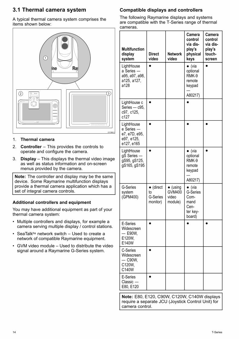
3.1 Thermal camera systemA typical thermal camera system comprises theitems shown below:
D11966-2
1
2 3
1. Thermal camera2. Controller – This provides the controls to
operate and configure the camera.3. Display – This displays the thermal video image
as well as status information and on-screenmenus provided by the camera.
Note: The controller and display may be the samedevice. Some Raymarine multifunction displaysprovide a thermal camera application which has aset of integral camera controls.
Additional controllers and equipmentYou may have additional equipment as part of yourthermal camera system:• Multiple controllers and displays, for example acamera serving multiple display / control stations.
• SeaTalkhs network switch – Used to create anetwork of compatible Raymarine equipment.
• GVM video module – Used to distribute the videosignal around a Raymarine G-Series system.
Compatible displays and controllersThe following Raymarine displays and systemsare compatible with the T-Series range of thermalcameras.
Multifunctiondisplaysystem
Directvideo
Networkvideo
Cameracontrolvia dis-play’sphysicalkeys
Cameracontrolvia dis-play’stouch-screen
LightHousea Series —a95, a97, a98,a125, a127,a128
● ● (viaoptionalRMK-9remotekeypad—A80217)
●
LightHouse cSeries — c95,c97, c125,c127
● ●
LightHousee Series —e7, e7D, e95,e97, e125,e127, e165
● ● ●
LightHousegS Series —gS95, gS125,gS165, gS195
● ● (viaoptionalRMK-9remotekeypad—A80217)
●
G-Seriessystem(GPM400)
● (directtoG-Seriesmonitor)
● (usingGVM400videomodule)
● (viaG-SeriesCom-mandCen-ter key-board)
E-SeriesWidescreen— E90W,E120W,E140W
● ● ●
C-SeriesWidescreen— C90W,C120W,C140W
●
E-SeriesClassic —E80, E120
●
Note: E80, E120, C90W, C120W, C140W displaysrequire a separate JCU (Joystick Control Unit) forcamera control.
14 T-Series
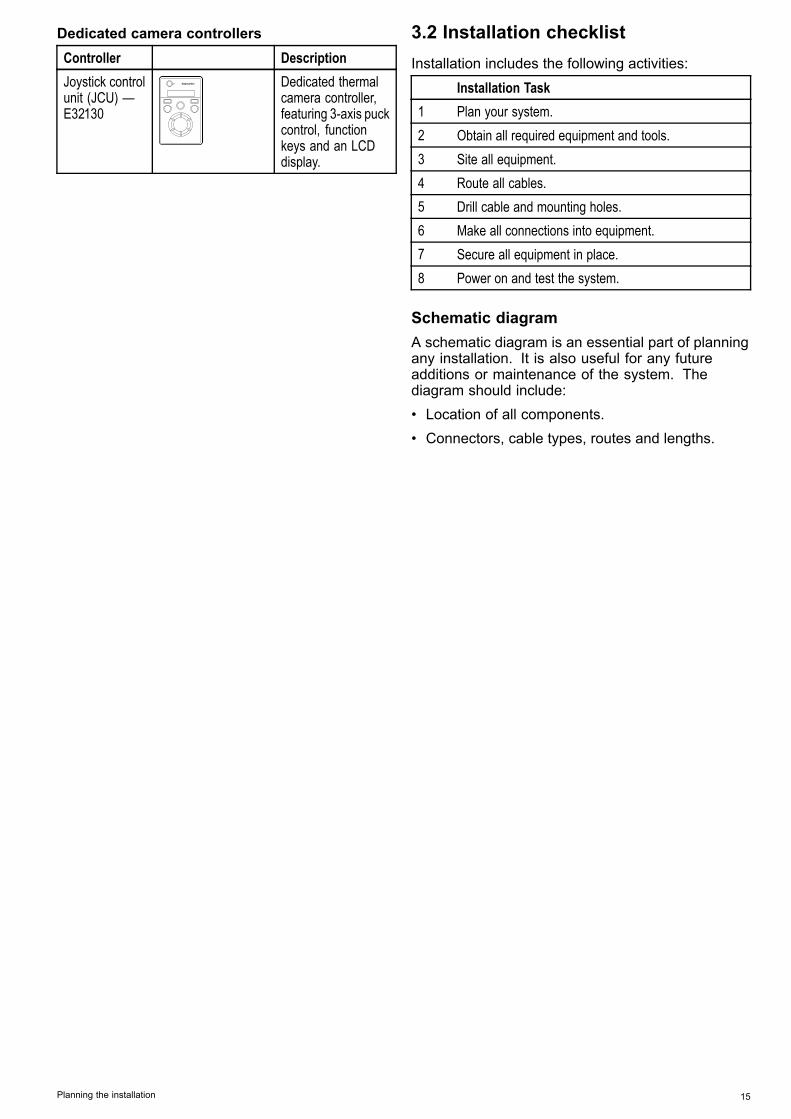
Dedicated camera controllersController DescriptionJoystick controlunit (JCU) —E32130
Dedicated thermalcamera controller,featuring 3-axis puckcontrol, functionkeys and an LCDdisplay.
3.2 Installation checklistInstallation includes the following activities:
Installation Task1 Plan your system.2 Obtain all required equipment and tools.3 Site all equipment.4 Route all cables.5 Drill cable and mounting holes.6 Make all connections into equipment.7 Secure all equipment in place.8 Power on and test the system.
Schematic diagramA schematic diagram is an essential part of planningany installation. It is also useful for any futureadditions or maintenance of the system. Thediagram should include:• Location of all components.• Connectors, cable types, routes and lengths.
Planning the installation 15

3.3 Typical systems with thermal camerasExample system with fully integrated display
6
D11964-2
1 3 4 52
Video cable – Carries the thermal / visible light videoimage.
SeaTalkhs – Includes the camera controlcommunications.
1 e/c-series display 4 PoE injector (Required if JCU is included in the system.)2 Thermal camera 5 JCU (optional)3 Raymarine network switch 6 SeaTalkhs to other digital devices: Additional displays /
controllers, Radar, etc.
G-Series system99WWXXYYZZ88TTUUVV77PPQQRRSS44GGHHII55JJKKLL66MMNNOOAACCTTIIVVEEWWPPTTSSMMOOBBDDAATTAAMMEENNUUPPAAGGEE..0022AABBCC33DDEEFF11CCAANNCCEELLSSTTAANNDDBBYYDDOODDGGEEPPIILLOOTTOOKKRRAANNGGEEOOUUTTIINNEENNTTEERRD11965-2
3 4
6 8 9
1 2
5 7
Video cable SeaTalkhs – Includes the camera controlcommunications (and video signal on G-Seriessystem).
1 G-Series Nav station 6 G-Series GVM400 video module2 Repeat monitor 7 Thermal camera3 G-Series GPM400 8 JCU (optional)
16 T-Series
4 Raymarine network switch 9 PoE injector (Required if JCU is included in the system.)5 Glass bridge monitor
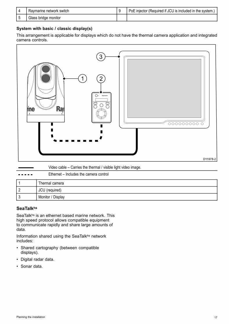
System with basic / classic display(s)This arrangement is applicable for displays which do not have the thermal camera application and integratedcamera controls.
D11978-2
1
3
2
Video cable – Carries the thermal / visible light video image.Ethernet – Includes the camera control
1 Thermal camera2 JCU (required)3 Monitor / Display
SeaTalkhs
SeaTalkhs is an ethernet based marine network. Thishigh speed protocol allows compatible equipmentto communicate rapidly and share large amounts ofdata.Information shared using the SeaTalkhs networkincludes:• Shared cartography (between compatibledisplays).
• Digital radar data.• Sonar data.
Planning the installation 17

3.4 Thermal camera parts supplied
x6 x6 x6
x6
D11968-2
2
5
6
1
3
4
1. T-Series thermal camera2. Mounting fasteners3. Ethernet waterproof coupler4. Small O-ring5. Large O-ring6. Documentation pack (containing: camera
mounting template, warranty policy anddocumentation CD.)
Unpack the camera unit carefully to prevent damage.Save the carton and packing in case the unit has tobe returned for service.
Additional items requiredTo complete the installation you will also need toobtain the following items:• Compatible display / control hardware.• Cables for power, ground, video and networkconnection.
• Thread locking compound (for example Loctite242 or equivalent), required for all metal-to-metalthreaded connections.
Optional accessoriesYou may also require the following items:• Optional top-down riser / galvanic isolation kit(A80334). The kit comprises a riser, gasket, andadditional mounting fasteners, and is required ifeither of the following conditions apply:– the camera is to be mounted on a surface withrestricted access to the underside.
– the camera is to be mounted on a metallicsurface (for example, steel), which couldotherwise cause galvanic corrosion between thecamera base and the mounting point.
3.5 JCU — Parts suppliedT-Series thermal cameras with JCU included aresupplied with the following additional parts:
D11967-2
1
3
2
4
5
78.74 ±1.25 mm (3.1 ±0.049 in) cutout6.4 mm(0.25 in)diameter
72.4 mm (2.9 in) optional drill guide
90.4 mm (3.6 in) outside of JCU
129.
54 ±
1.25
mm
(5.1
±0.
049
in) c
utou
t
123.
2 m
m (4
.9 in
) opt
iona
l dril
l gui
de
141.
4 m
m (5
.6 in
) out
side
of J
CU
This
doc
umen
t may
not
prin
t tru
e to
sca
le. B
efor
e m
odify
ing
mou
ntin
g su
rface
, ens
ure
prin
ted
tem
plat
e m
atch
es th
e m
easu
rem
ents
pro
vide
d.
D11
991
-1
6
1. Joystick Control Unit (JCU).2. Bezel.3. Sun cover.4. Mounting template5. Power over Ethernet (PoE) injector.6. PoE cable 1.5 m (5 ft).
Note: The JCU part number E32130 can also beordered separately.
18 T-Series
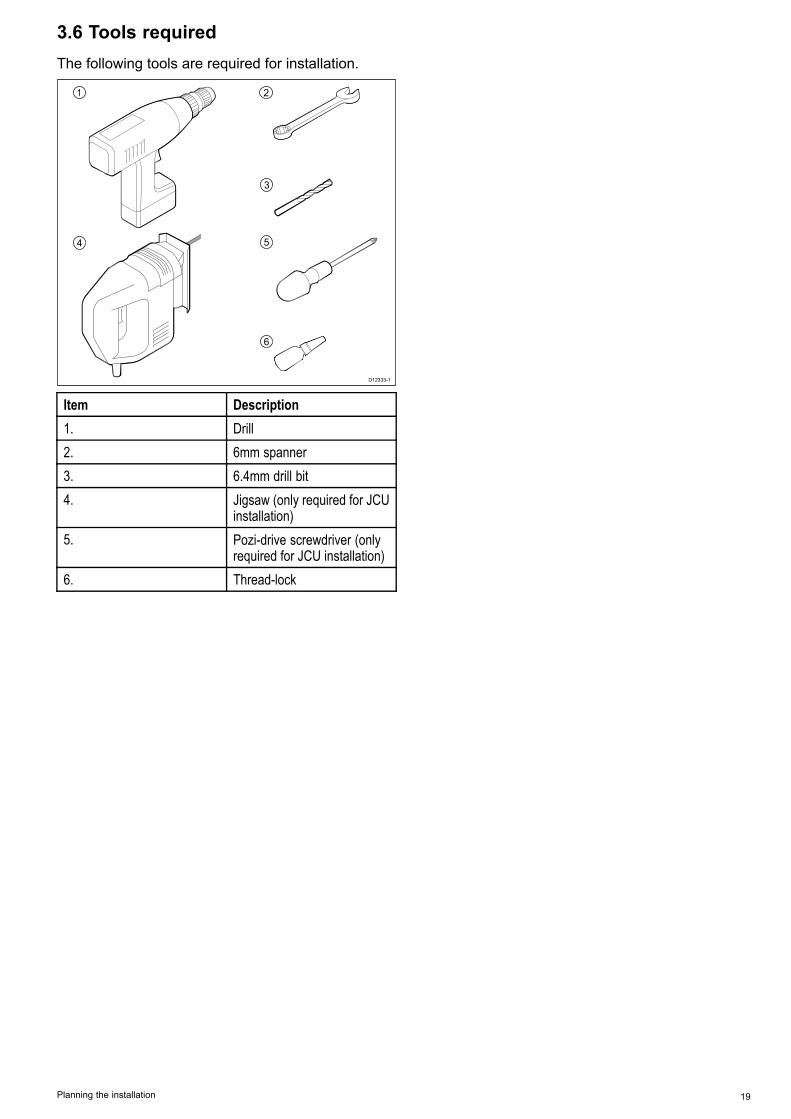
3.6 Tools requiredThe following tools are required for installation.
D12333-1
1 2
3
4 5
6
Item Description1. Drill2. 6mm spanner3. 6.4mm drill bit4. Jigsaw (only required for JCU
installation)5. Pozi-drive screwdriver (only
required for JCU installation)6. Thread-lock
Planning the installation 19

20 T-Series

Chapter 4: Cables and connections
Chapter contents• 4.1 General cabling guidance on page 22• 4.2 Connection overview on page 23• 4.3 Power connection on page 26• 4.4 JCU Connection on page 27
Cables and connections 21

4.1 General cabling guidance
Cable types and lengthIt is important to use cables of the appropriate typeand length• Unless otherwise stated use only standard cablesof the correct type, supplied by Raymarine.
• Ensure that any non-Raymarine cables are of thecorrect quality and gauge. For example, longerpower cable runs may require larger wire gaugesto minimize voltage drop along the run.
Routing cablesCables must be routed correctly, to maximizeperformance and prolong cable life.• Do NOT bend cables excessively. Whereverpossible, ensure a minimum bend diameter of 200mm (8 in) / minimum bend radius of 100 mm (4 in).
100 mm (4 in)
200 mm (8 in)
• Protect all cables from physical damage andexposure to heat. Use trunking or conduit wherepossible. Do NOT run cables through bilges ordoorways, or close to moving or hot objects.
• Secure cables in place using tie-wraps or lacingtwine. Coil any extra cable and tie it out of the way.
• Where a cable passes through an exposedbulkhead or deckhead, use a suitable watertightfeed-through.
• Do NOT run cables near to engines or fluorescentlights.
Always route data cables as far away as possiblefrom:• other equipment and cables,• high current carrying ac and dc power lines,• antennae.
Strain reliefEnsure adequate strain relief is provided. Protectconnectors from strain and ensure they will not pullout under extreme sea conditions.
Circuit isolationAppropriate circuit isolation is required forinstallations using both AC and DC current:• Always use isolating transformers or a separatepower-inverter to run PC’s, processors, displaysand other sensitive electronic instruments ordevices.
• Always use an isolating transformer with WeatherFAX audio cables.
• Always use an isolated power supply when usinga 3rd party audio amplifier.
• Always use an RS232/NMEA converter withoptical isolation on the signal lines.
• Always make sure that PC’s or other sensitiveelectronic devices have a dedicated power circuit.
Cable shieldingEnsure that all data cables are properly shieldedthat the cable shielding is intact (e.g. hasn’t beenscraped off by being squeezed through a tight area).
22 T-Series
4.2 Connection overview
D11957-1
21 43
5
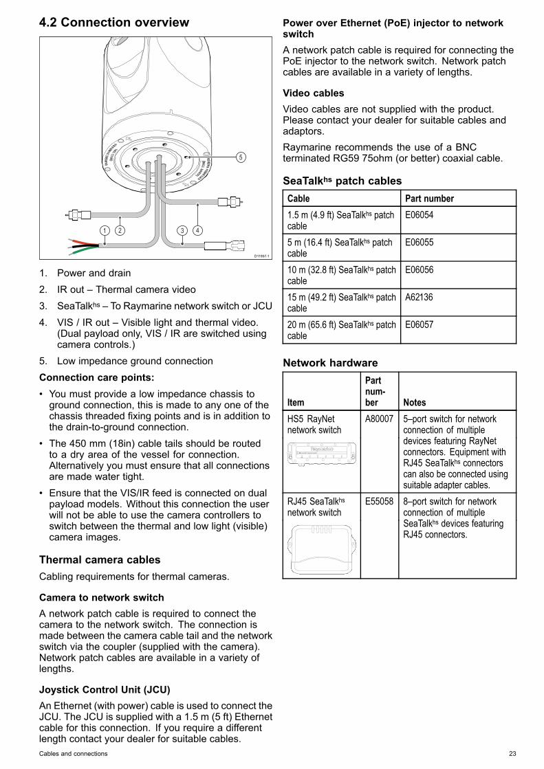
1. Power and drain2. IR out – Thermal camera video3. SeaTalkhs – To Raymarine network switch or JCU4. VIS / IR out – Visible light and thermal video.
(Dual payload only, VIS / IR are switched usingcamera controls.)
5. Low impedance ground connectionConnection care points:• You must provide a low impedance chassis toground connection, this is made to any one of thechassis threaded fixing points and is in addition tothe drain-to-ground connection.
• The 450 mm (18in) cable tails should be routedto a dry area of the vessel for connection.Alternatively you must ensure that all connectionsare made water tight.
• Ensure that the VIS/IR feed is connected on dualpayload models. Without this connection the userwill not be able to use the camera controllers toswitch between the thermal and low light (visible)camera images.
Thermal camera cablesCabling requirements for thermal cameras.
Camera to network switchA network patch cable is required to connect thecamera to the network switch. The connection ismade between the camera cable tail and the networkswitch via the coupler (supplied with the camera).Network patch cables are available in a variety oflengths.
Joystick Control Unit (JCU)An Ethernet (with power) cable is used to connect theJCU. The JCU is supplied with a 1.5 m (5 ft) Ethernetcable for this connection. If you require a differentlength contact your dealer for suitable cables.
Power over Ethernet (PoE) injector to networkswitchA network patch cable is required for connecting thePoE injector to the network switch. Network patchcables are available in a variety of lengths.
Video cablesVideo cables are not supplied with the product.Please contact your dealer for suitable cables andadaptors.Raymarine recommends the use of a BNCterminated RG59 75ohm (or better) coaxial cable.
SeaTalkhs patch cablesCable Part number1.5 m (4.9 ft) SeaTalkhs patchcable
E06054
5 m (16.4 ft) SeaTalkhs patchcable
E06055
10 m (32.8 ft) SeaTalkhs patchcable
E06056
15 m (49.2 ft) SeaTalkhs patchcable
A62136
20 m (65.6 ft) SeaTalkhs patchcable
E06057
Network hardware
Item
Partnum-ber Notes
HS5 RayNetnetwork switch
A80007 5–port switch for networkconnection of multipledevices featuring RayNetconnectors. Equipment withRJ45 SeaTalkhs connectorscan also be connected usingsuitable adapter cables.
RJ45 SeaTalkhsnetwork switch
E55058 8–port switch for networkconnection of multipleSeaTalkhs devices featuringRJ45 connectors.
Cables and connections 23
Item
Partnum-ber Notes
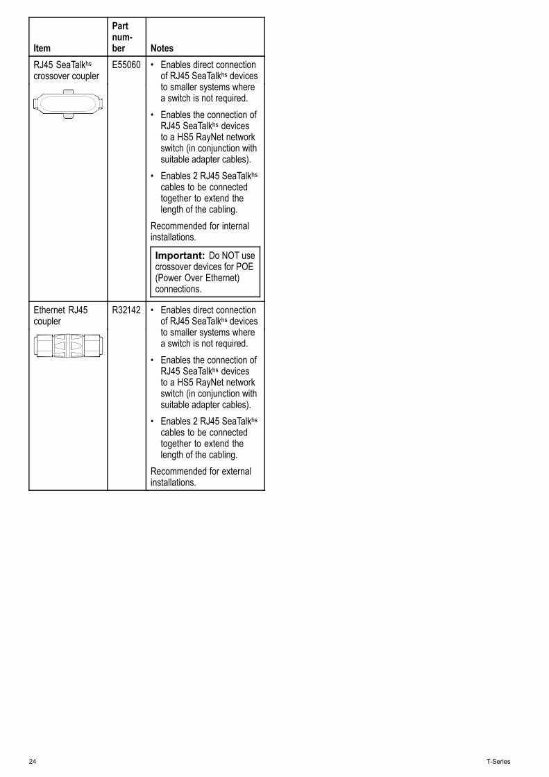
RJ45 SeaTalkhscrossover coupler
E55060 • Enables direct connectionof RJ45 SeaTalkhs devicesto smaller systems wherea switch is not required.
• Enables the connection ofRJ45 SeaTalkhs devicesto a HS5 RayNet networkswitch (in conjunction withsuitable adapter cables).
• Enables 2 RJ45 SeaTalkhscables to be connectedtogether to extend thelength of the cabling.
Recommended for internalinstallations.
Important: Do NOT usecrossover devices for POE(Power Over Ethernet)connections.
Ethernet RJ45coupler
R32142 • Enables direct connectionof RJ45 SeaTalkhs devicesto smaller systems wherea switch is not required.
• Enables the connection ofRJ45 SeaTalkhs devicesto a HS5 RayNet networkswitch (in conjunction withsuitable adapter cables).
• Enables 2 RJ45 SeaTalkhscables to be connectedtogether to extend thelength of the cabling.
Recommended for externalinstallations.
24 T-Series
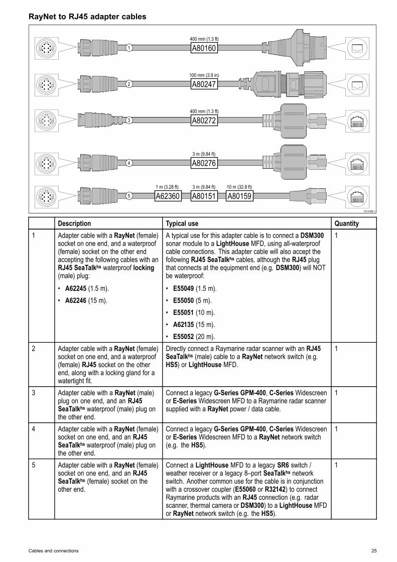
RayNet to RJ45 adapter cables
D13158-1
1
2
3
4
5
A80160400 mm (1.3 ft)
A801513 m (9.84 ft)
A8015910 m (32.8 ft)
A623601 m (3.28 ft)
A802763 m (9.84 ft)
A80272400 mm (1.3 ft)
A80247100 mm (3.9 in)
Description Typical use Quantity1 Adapter cable with a RayNet (female)
socket on one end, and a waterproof(female) socket on the other endaccepting the following cables with anRJ45 SeaTalkhs waterproof locking(male) plug:
• A62245 (1.5 m).• A62246 (15 m).
A typical use for this adapter cable is to connect a DSM300sonar module to a LightHouse MFD, using all-waterproofcable connections. This adapter cable will also accept thefollowing RJ45 SeaTalkhs cables, although the RJ45 plugthat connects at the equipment end (e.g. DSM300) will NOTbe waterproof:
• E55049 (1.5 m).• E55050 (5 m).• E55051 (10 m).• A62135 (15 m).• E55052 (20 m).
1
2 Adapter cable with a RayNet (female)socket on one end, and a waterproof(female) RJ45 socket on the otherend, along with a locking gland for awatertight fit.
Directly connect a Raymarine radar scanner with an RJ45SeaTalkhs (male) cable to a RayNet network switch (e.g.HS5) or LightHouse MFD.
1
3 Adapter cable with a RayNet (male)plug on one end, and an RJ45SeaTalkhs waterproof (male) plug onthe other end.
Connect a legacy G-Series GPM-400, C-SeriesWidescreenor E-Series Widescreen MFD to a Raymarine radar scannersupplied with a RayNet power / data cable.
1
4 Adapter cable with a RayNet (female)socket on one end, and an RJ45SeaTalkhs waterproof (male) plug onthe other end.
Connect a legacy G-Series GPM-400, C-SeriesWidescreenor E-Series Widescreen MFD to a RayNet network switch(e.g. the HS5).
1
5 Adapter cable with a RayNet (female)socket on one end, and an RJ45SeaTalkhs (female) socket on theother end.
Connect a LightHouse MFD to a legacy SR6 switch /weather receiver or a legacy 8–port SeaTalkhs networkswitch. Another common use for the cable is in conjunctionwith a crossover coupler (E55060 or R32142) to connectRaymarine products with an RJ45 connection (e.g. radarscanner, thermal camera or DSM300) to a LightHouse MFDor RayNet network switch (e.g. the HS5).
1
Cables and connections 25
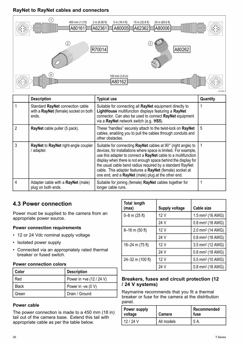
RayNet to RayNet cables and connectors
D13160-1
4
2 3
1
A80161 A62361 A80005 A62362 A80006400 mm (1.3 ft) 2 m (6.56 ft) 5 m (16.4 ft) 10 m (32.8 ft) 20 m (65.6 ft)
A80162100 mm (3.9 in)
R70014 A80262
Description Typical use Quantity1 Standard RayNet connection cable
with a RayNet (female) socket on bothends.
Suitable for connecting all RayNet equipment directly toLightHouse multifunction displays featuring a RayNetconnector. Can also be used to connect RayNet equipmentvia a RayNet network switch (e.g. HS5).
1
2 RayNet cable puller (5 pack). These “handles” securely attach to the twist-lock on RayNetcables, enabling you to pull the cables through conduits andother obstacles.
5
3 RayNet to RayNet right-angle coupler/ adapter.
Suitable for connecting RayNet cables at 90° (right angle) todevices, for installations where space is limited. For example,use this adapter to connect a RayNet cable to a multifunctiondisplay when there is not enough space behind the display forthe usual cable bend radius required by a standard RayNetcable. This adapter features a RayNet (female) socket atone end, and a RayNet (male) plug at the other end.
1
4 Adapter cable with a RayNet (male)plug on both ends.
Suitable for joining (female) RayNet cables together forlonger cable runs.
1
4.3 Power connectionPower must be supplied to the camera from anappropriate power source.
Power connection requirements• 12 or 24 Vdc nominal supply voltage• Isolated power supply• Connected via an appropriately rated thermalbreaker or fused switch.
Power connection colorsColor DescriptionRed Power in +ve (12 / 24 V)Black Power in -ve (0 V)Green Drain / Ground
Power cableThe power connection is made to a 450 mm (18 in)tail out of the camera base. Extend this tail withappropriate cable as per the table below.
Total length(max) Supply voltage Cable size
12 V 1.5 mm2 (16 AWG)0–8 m (25 ft)24 V 0.8 mm2 (18 AWG)12 V 2.0 mm2 (14 AWG)8–16 m (50 ft)24 V 0.8 mm2 (18 AWG)12 V 3.5 mm2 (12 AWG)16–24 m (75 ft)24 V 0.8 mm2 (18 AWG)12 V 5.5 mm2 (10 AWG)24–32 m (100 ft)24 V 0.8 mm2 (18 AWG)
Breakers, fuses and circuit protection (12/ 24 V systems)Raymarine recommends that you fit a thermalbreaker or fuse for the camera at the distributionpanel.
Power supplyvoltage Camera
Recommendedfuse
12 / 24 V All models 5 A.
26 T-Series
Sharing a breakerWhere more than 1 piece of equipment shares abreaker you must provide protection for the individualcircuits. E.g. by connecting an in-line fuse for eachpower circuit.
D11637-2
2
4 4
1
3
+ -
1 Positive (+) bar2 Negative (-) bar3 Circuit breaker4 Fuse
Where possible, connect individual items ofequipment to individual circuit breakers. Where thisis not possible, use individual in-line fuses to providethe necessary protection.
Grounding — Dedicated drain wireThe power cable supplied with this product includesa dedicated shield (drain) wire for connection to avessel's RF ground point.It is important that an effective RF ground isconnected to the system. A single ground pointshould be used for all equipment. The unit can begrounded by connecting the shield (drain) wire ofthe power cable to the vessel's RF ground point.On vessels without an RF ground system the shield(drain) wire should be connected directly to thenegative battery terminal.The dc power system should be either:• Negative grounded, with the negative batteryterminal connected to the vessel's ground.
• Floating, with neither battery terminal connectedto the vessel's ground
Warning: Positive ground systemsDo not connect this unit to a system whichhas positive grounding.
4.4 JCU ConnectionThe JCU (Joystick Control Unit) can be connectedas part of the SeaTalkhs network. Alternatively itcan be connected directly to the thermal cameraprovided that there are no other camera controllerson the system.
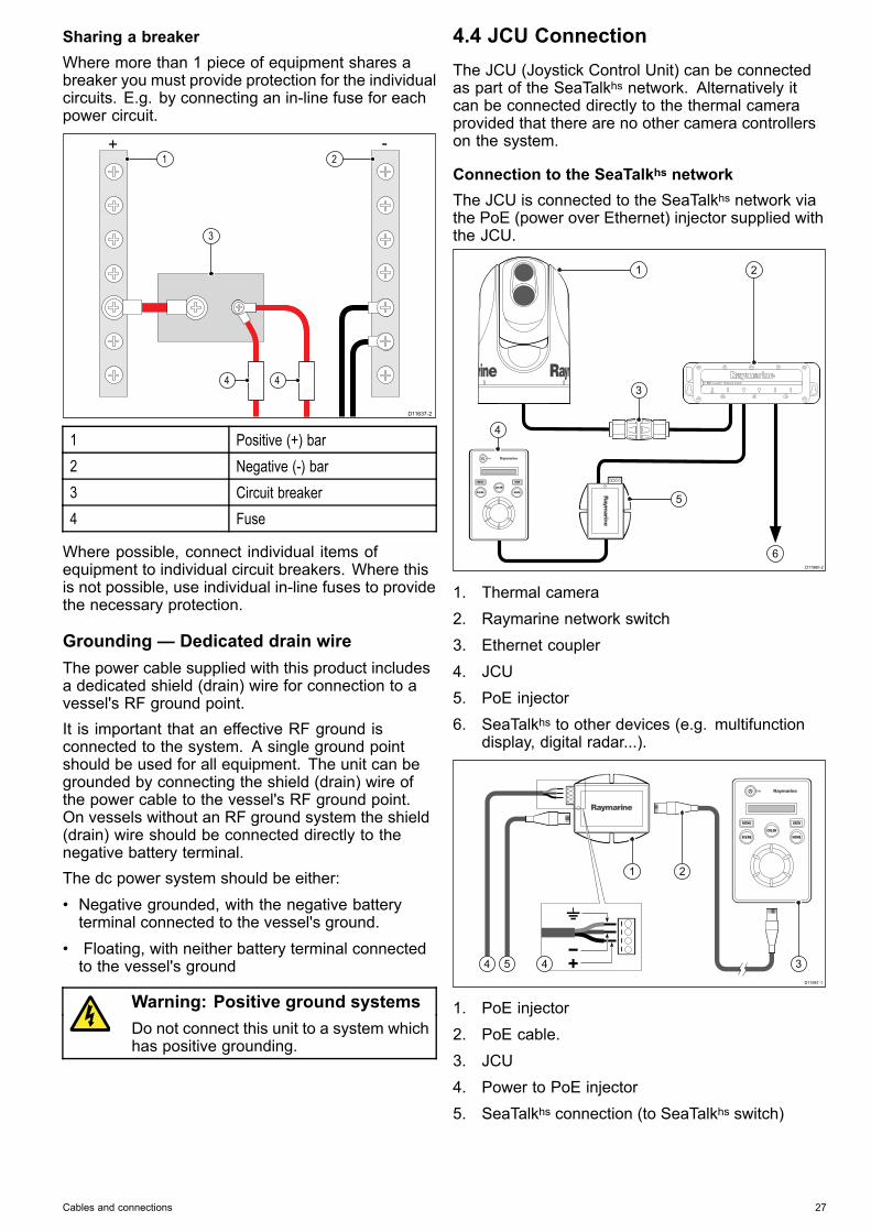
Connection to the SeaTalkhs networkThe JCU is connected to the SeaTalkhs network viathe PoE (power over Ethernet) injector supplied withthe JCU.
D11980-2
1
5
3
4
6
2
1. Thermal camera2. Raymarine network switch3. Ethernet coupler4. JCU5. PoE injector6. SeaTalkhs to other devices (e.g. multifunction
display, digital radar...).
D11981-1
54 4
21
3
1. PoE injector2. PoE cable.3. JCU4. Power to PoE injector5. SeaTalkhs connection (to SeaTalkhs switch)
Cables and connections 27
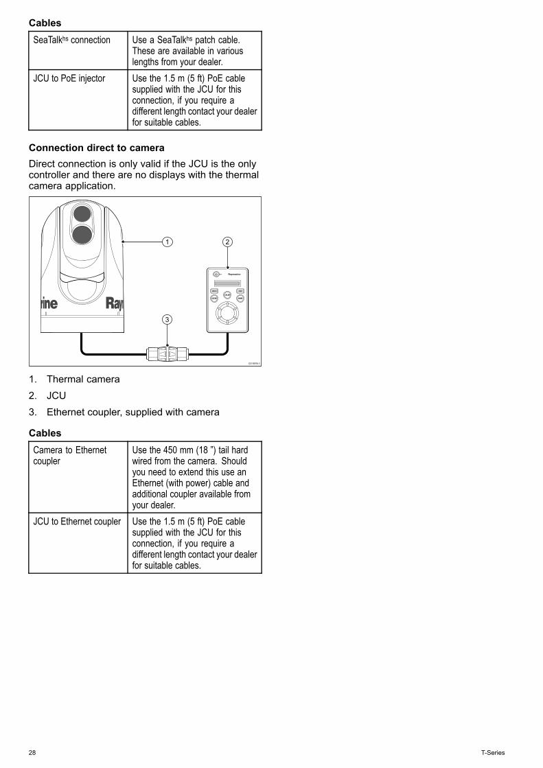
CablesSeaTalkhs connection Use a SeaTalkhs patch cable.
These are available in variouslengths from your dealer.
JCU to PoE injector Use the 1.5 m (5 ft) PoE cablesupplied with the JCU for thisconnection, if you require adifferent length contact your dealerfor suitable cables.
Connection direct to cameraDirect connection is only valid if the JCU is the onlycontroller and there are no displays with the thermalcamera application.
D11979-1
1 2
3
1. Thermal camera2. JCU3. Ethernet coupler, supplied with camera
CablesCamera to Ethernetcoupler
Use the 450 mm (18 ”) tail hardwired from the camera. Shouldyou need to extend this use anEthernet (with power) cable andadditional coupler available fromyour dealer.
JCU to Ethernet coupler Use the 1.5 m (5 ft) PoE cablesupplied with the JCU for thisconnection, if you require adifferent length contact your dealerfor suitable cables.
28 T-Series

Chapter 5: Installation
Chapter contents• 5.1 Camera mounting on page 30• 5.2 JCU Mounting on page 32
Installation 29
5.1 Camera mounting
Location requirementWhen planning the installation location, consider thefollowing points:• The camera is waterproof, and appropriate forabove decks mounting.
• When mounting the camera in a ball-downposition, ensure that the camera is installed withadequate drainage so that standing water doesnot collect above the cable glands. Standing waterwill eventually seep past the cable gland seals andcompromise the internal electronics.
• If the base of the T-Series camera must be leftexposed, the exit holes must be sealed witha marine-grade adhesive such as 3M 5200 orequivalent. Use a sufficient amount of sealant toprevent pooling of water above the glands. Failureto properly install or seal these glands could voidthe camera warranty.
• Ensure the camera is installed in a locationthat will allow it to be accessed for regularperiodic cleaning (fresh-water rinse), inspectionof mounting point integrity and mechanicalsoundness, and preventative maintenance.
• The underside (inside) of the compartment ordeck on to which the camera is mounted must beweather-tight. You must ensure protection fromwater ingress to cables and connections.
• The mounting surface must be horizontal.• If you cannot access both sides of the mountingsurface, then you will need to mount the camera“top down” using the optional top-down riser /galvanic isolation kit (A80334).
• If the mounting surface is metallic (for example,steel), then you will need to mount the camera “topdown” using the optional top-down riser / galvanicisolation kit (A80334). The riser provides galvanicisolation and protection from galvanic corrosion.
• Fixings are supplied for a mounting surface ofup to 41 mm (1.6 in) thick. A thicker surface willrequire the installer to provide alternative fixings.
• The camera mounting surface must be at least aslarge as the footprint of the camera itself to ensurean adequate seal with the O-ring.
• The camera should be mounted as high aspractical, but without interfering with any radar,navigational or communications electronics.
• Choose a location that will provide the mostunobstructed view in all directions.
• Choose a location as close to the vessel’s centerline as possible. This provides a symmetrical viewwhen looking forward or aft.
• Select a location for the camera that is at least 7cm (2.75 in.) from any magnetic compass.
• Select a location that is at least 1 m (3 ft) fromdevices that may cause interference, such asmotors, generators and radio transmitters /receivers.
• If installing an optional JCU, select a location forthe JCU that is at least 11 cm (4.33 in.) from anymagnetic compass.
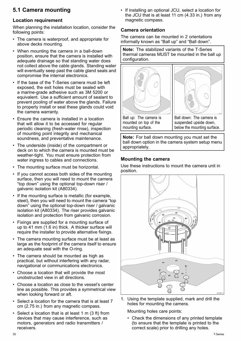
Camera orientationThe camera can be mounted in 2 orientationsinformally known as “Ball up” and “Ball down”.
Note: The stabilized variants of the T-Seriesthermal cameras MUST be mounted in the ball upconfiguration.
D11975-1
Ball up: The camera ismounted on top of themounting surface.
D11976-1
Ball down: The camera issuspended upside down,below the mounting surface.
Note: For ball down mounting you must set theball down option in the camera system setup menuappropriately.
Mounting the cameraUse these instructions to mount the camera unit inposition.
D11971-1
1. Using the template supplied, mark and drill theholes for mounting the camera.
Mounting holes care points:• Check the dimensions of any printed template(to ensure that the template is printed to thecorrect scale) prior to drilling any holes.
30 T-Series

• Note the camera forward markings on thecamera base, and make sure the template isoriented properly relative to the bow of thevessel. This is affected by whether the camerais to be mounted ball-up or ball-down.
2. Install the 6x threaded studs into the base ofthe camera with thread-locking compound. Ifrequired, you can use studs of a different lengthto suit your installation.
Tighten the studs to a torque of 9.5 Nm (7 lb-ft).3. Install the rubber O-ring in the base of the
camera.4. Thread the power supply, video, and network
cables from the camera through the center hole,and then place the camera on the mountingsurface so the threaded studs extend through thedrilled holes.
5. Make the required cable connections to thecamera tails.
6. Secure the camera body to the mounting surfacewith the supplied nuts and washers.
Dome capped nuts are provided for a neatersolution where the mounting is exposed to view.
You must ensure a watertight seal. You may usea marine-grade sealant as an alternative to themounting O-ring.
Mounting the camera with the optionaltop-down riser / galvanic isolation kit(A80334)The optional top-down riser / galvanic isolation kit(A80334) is used when access to the undersideof the mounting surface is restricted, or if galvanicisolation is required when mounting to a metallicsurface. Use the instructions below to mount thecamera unit using the optional top-down riser /galvanic isolation kit (A80334).1. Use the riser as a template to mark and drill the
holes for mounting the camera.• Note the camera forward marking on the topsurface of the riser. You must ensure that theriser is mounted so that the camera is orientedproperly relative to the bow of the vessel.
2. Fasten the camera unit to the riser using the6x threaded bolts and a suitable thread-lockingcompound.
D13238-1
• Note the camera forward markings on thecamera base and on the top surface of the riser.You must ensure that the camera is facingthe correct way depending upon whether thecamera is to be mounted ball-up or ball-down.
• Ensure the rubber O-ring is positioned correctlyin the base of the camera.
3. Make the required cable connections to thecamera tails.
4. Fasten the camera-riser assembly to themounting surface using fasteners appropriate forthe surface’s thickness and material.
D13237-1
You must ensure a watertight seal. You may usea marine-grade sealant as an alternative to thesupplied mounting gasket.
Installation 31
5.2 JCU Mounting
Location requirementsWhen planning the installation location, consider thefollowing points:• Select a position on your vessel that is close tothe monitor that displays the T-Series cameravideo output.
• Ensure the JCU is mounted at least 55 cm (21.7")away from any equipment fitted with a magneticcompass.
• The JCU can be mounted to a dash or othersurface in any orientation.
• Consider cable lengths and cable routing.
Flush mountingThe standard method for mounting the JCU is a flushor panel mounting arrangement.Before mounting the unit, ensure that you have:• Selected a suitable location. A clear, flat area withsuitable clearance behind the panel is required.
• Identified the cable connection required and theroute that the cable will take.
• Detached the front bezel to reveal the mountingscrews.
Mounting the JCU1. Cut the mounting hole according to the
dimensions specified in the mounting templateincluded in this document.
2. Ensure that the unit fits into the removed areaand then file around the cut edge until smooth.
3. Drill four 6.4 mm (0.25 in) holes as indicated onthe template to accept the mounting screws.
4. Before mounting the JCU, insert the suppliedethernet cable through the mounting hole andinto the JCU ethernet port. Ensure the cablegland sealing nut is tightened correctly.
5. Remove the 4 panel mounting clamps and insertthe JCU in place. Affix the mounting clamps tothe screws on the other side of the mountingsurface, ensuring that the mounting clamps arerotated outward from the JCU housing. Tightenthe screws to draw the mounting clamps upagainst the mounting surface and then tightenanother 1/4 to 1/2 turn. Do not overtighten thescrews.i. As shipped from the factory, the JCU can
be mounted to a panel thickness rangingfrom 0.79 to 4.45 cm (0.31 to 1.750 in). Theclamps are set with the small “foot” on theclamp facing towards the mounting surface,away from the front of the JCU, as shown inthe "Thick panel mounting" diagram in thisdocument.
ii. To mount the JCU to a panel thickness of0.79 cm (0.31 in) or less, remove the clampsfrom the mounting screws, turn them aroundand thread them back onto each of the fourscrews. In this configuration, the clamp
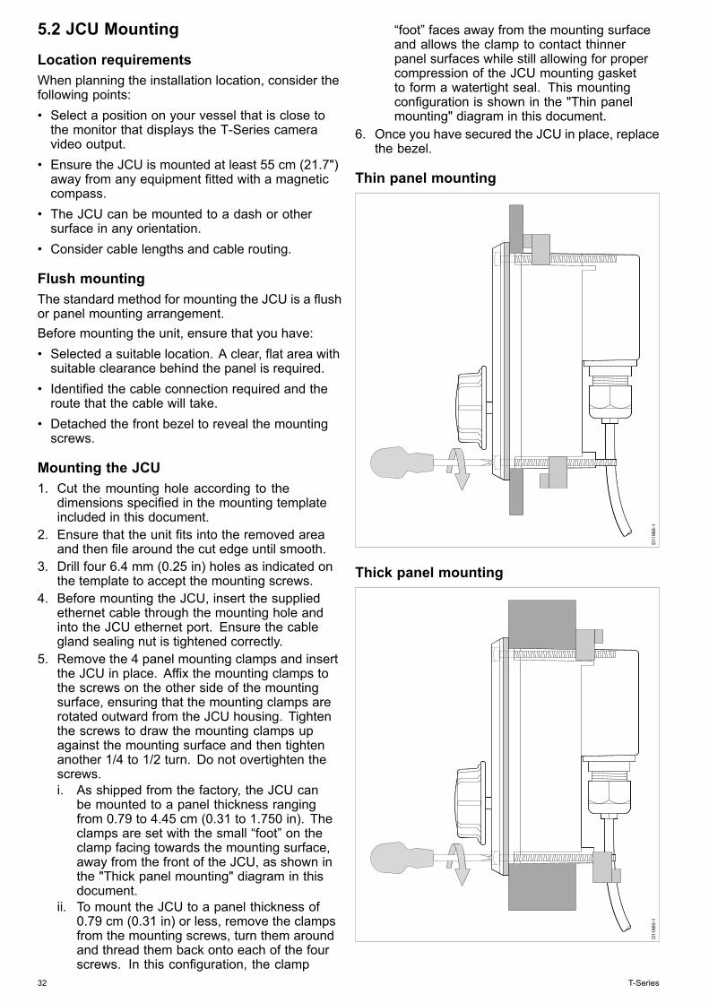
“foot” faces away from the mounting surfaceand allows the clamp to contact thinnerpanel surfaces while still allowing for propercompression of the JCU mounting gasketto form a watertight seal. This mountingconfiguration is shown in the "Thin panelmounting" diagram in this document.
6. Once you have secured the JCU in place, replacethe bezel.
Thin panel mounting
D11
989-
1
Thick panel mounting
D11
990-
1
32 T-Series

Chapter 6: System operation and setup
Chapter contents• 6.1 Thermal camera image on page 34• 6.2 Operation and features overview on page 35• 6.3 Power up and standby on page 36• 6.4 Camera control on page 37• 6.5 Image adjustments on page 39• 6.6 System reset on page 40• 6.7 Setup menus on page 41
System operation and setup 33
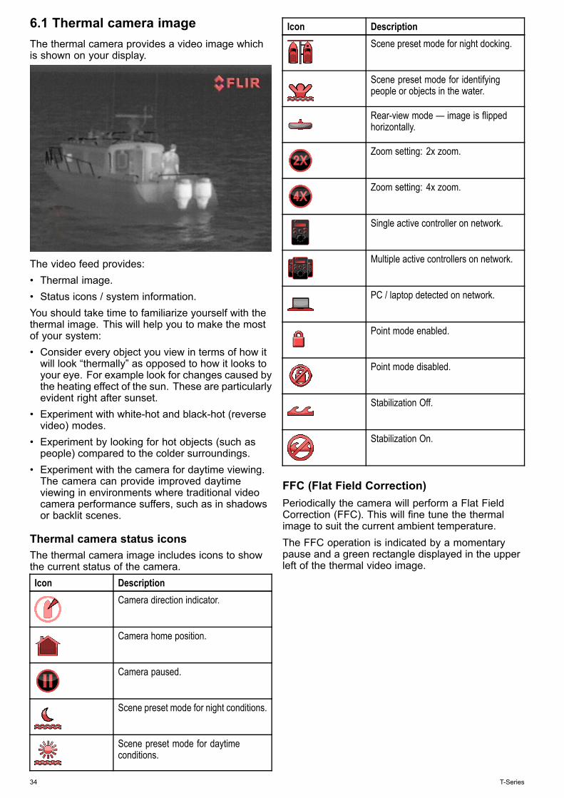
6.1 Thermal camera imageThe thermal camera provides a video image whichis shown on your display.
The video feed provides:• Thermal image.• Status icons / system information.You should take time to familiarize yourself with thethermal image. This will help you to make the mostof your system:• Consider every object you view in terms of how itwill look “thermally” as opposed to how it looks toyour eye. For example look for changes caused bythe heating effect of the sun. These are particularlyevident right after sunset.
• Experiment with white-hot and black-hot (reversevideo) modes.
• Experiment by looking for hot objects (such aspeople) compared to the colder surroundings.
• Experiment with the camera for daytime viewing.The camera can provide improved daytimeviewing in environments where traditional videocamera performance suffers, such as in shadowsor backlit scenes.
Thermal camera status iconsThe thermal camera image includes icons to showthe current status of the camera.Icon Description
Camera direction indicator.
Camera home position.
Camera paused.
Scene preset mode for night conditions.
Scene preset mode for daytimeconditions.
Icon DescriptionScene preset mode for night docking.
Scene preset mode for identifyingpeople or objects in the water.
Rear-view mode — image is flippedhorizontally.
Zoom setting: 2x zoom.
Zoom setting: 4x zoom.
Single active controller on network.
Multiple active controllers on network.
PC / laptop detected on network.
Point mode enabled.
Point mode disabled.
Stabilization Off.
Stabilization On.
FFC (Flat Field Correction)Periodically the camera will perform a Flat FieldCorrection (FFC). This will fine tune the thermalimage to suit the current ambient temperature.The FFC operation is indicated by a momentarypause and a green rectangle displayed in the upperleft of the thermal video image.
34 T-Series
6.2 Operation and features overviewThe camera features can be accessed usingthe thermal camera application of a compatibleRaymarine multifunction display, or from a dedicatedJCU (Joystick control unit).This handbook covers methods using the JCU,for details on how to operate this product using acompatible Raymarine multifunction display pleaserefer to the thermal camera application section of themanual supplied with your multifunction display.The main Thermal camera operations are outlinedbelow:Control the camera:• Switch the camera between operational andstandby modes.
• Pan and tilt• Zoom• Home position• Pause the camera image• Switch between visible light and thermal cameralenses. (Dual payload only)
• Surveillance modeAdjust the camera image:• Color palette• Scene presets• Reverse video (white hot / black hot)In addition to the above, the camera also providessetup menus to configure the system to yourrequirements.
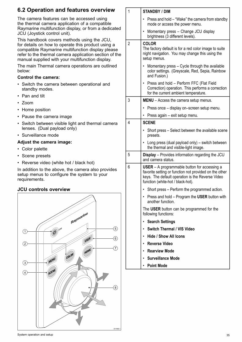
JCU controls overview
D11956-1
1
3
4
6
5
7
8
2
1 STANDBY / DIM
• Press and hold – “Wake” the camera from standbymode or access the power menu.
• Momentary press – Change JCU displaybrightness (3 different levels).
2 COLORThe factory default is for a red color image to suitenight navigation. You may change this using thesetup menus.
• Momentary press – Cycle through the availablecolor settings. (Greyscale, Red, Sepia, Rainbowand Fusion.)
• Press and hold – Perform FFC (Flat FieldCorrection) operation. This performs a correctionfor the current ambient temperature.
3 MENU – Access the camera setup menus.
• Press once – display on–screen setup menu.• Press again – exit setup menu.
4 SCENE
• Short press – Select between the available scenepresets.
• Long press (dual payload only) – switch betweenthe thermal and visible-light image.
5 Display – Provides information regarding the JCUand camera status.
6 USER – A programmable button for accessing afavorite setting or function not provided on the otherkeys. The default operation is the Reverse Videofunction (white-hot / black-hot).
• Short press – Perform the programmed action.• Press and hold – Program the USER button with
another function.The USER button can be programmed for thefollowing functions:
• Search Settings• Switch Thermal / VIS Video• Hide / Show All Icons• Reverse Video• Rearview Mode• Surveillance Mode• Point Mode
System operation and setup 35
7 HOME
• Momentary press – Return camera to homeposition.
• Press and hold – Set current position as camerahome.
• 4 x press – Reset the camera (realign home andstow positions).
8 PUCK – Use the puck to control the camera andnavigate the setup menus.Control camera:
• Move up, down left right – Pan / Tilt camera.• Press down (and hold) – Zoom thermal image in .• Lift up – Zoom thermal image out.• Double-click (2 quick presses) – Pause thermal
image. (Move puck in any direction to unfreeze.)Navigate setup menus:
• Move up, down – Scroll through menu options.• Press down – Select highlighted menu option.
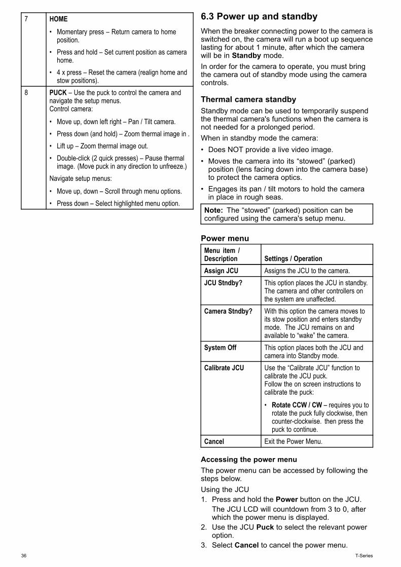
6.3 Power up and standbyWhen the breaker connecting power to the camera isswitched on, the camera will run a boot up sequencelasting for about 1 minute, after which the camerawill be in Standby mode.In order for the camera to operate, you must bringthe camera out of standby mode using the cameracontrols.
Thermal camera standbyStandby mode can be used to temporarily suspendthe thermal camera's functions when the camera isnot needed for a prolonged period.When in standby mode the camera:• Does NOT provide a live video image.• Moves the camera into its “stowed” (parked)position (lens facing down into the camera base)to protect the camera optics.
• Engages its pan / tilt motors to hold the camerain place in rough seas.
Note: The “stowed” (parked) position can beconfigured using the camera's setup menu.
Power menuMenu item /Description Settings / OperationAssign JCU Assigns the JCU to the camera.JCU Stndby? This option places the JCU in standby.
The camera and other controllers onthe system are unaffected.
Camera Stndby? With this option the camera moves toits stow position and enters standbymode. The JCU remains on andavailable to “wake” the camera.
System Off This option places both the JCU andcamera into Standby mode.
Calibrate JCU Use the “Calibrate JCU” function tocalibrate the JCU puck.Follow the on screen instructions tocalibrate the puck:
• Rotate CCW / CW – requires you torotate the puck fully clockwise, thencounter-clockwise. then press thepuck to continue.
Cancel Exit the Power Menu.
Accessing the power menuThe power menu can be accessed by following thesteps below.Using the JCU1. Press and hold the Power button on the JCU.
The JCU LCD will countdown from 3 to 0, afterwhich the power menu is displayed.
2. Use the JCU Puck to select the relevant poweroption.
3. Select Cancel to cancel the power menu.36 T-Series
Note: The power menu is only displayed on theJCU's LCD display.
6.4 Camera control
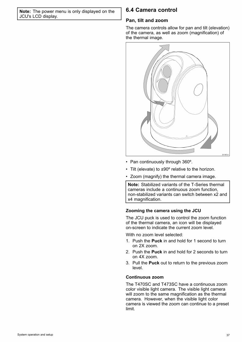
Pan, tilt and zoomThe camera controls allow for pan and tilt (elevation)of the camera, as well as zoom (magnification) ofthe thermal image.
D11973-1
• Pan continuously through 360º.• Tilt (elevate) to ±90º relative to the horizon.• Zoom (magnify) the thermal camera image.
Note: Stabilized variants of the T-Series thermalcameras include a continuous zoom function,non-stabilized variants can switch between x2 andx4 magnification.
Zooming the camera using the JCUThe JCU puck is used to control the zoom functionof the thermal camera, an icon will be displayedon-screen to indicate the current zoom level.With no zoom level selected:1. Push the Puck in and hold for 1 second to turn
on 2X zoom.2. Push the Puck in and hold for 2 seconds to turn
on 4X zoom.3. Pull the Puck out to return to the previous zoom
level.
Continuous zoomThe T470SC and T473SC have a continuous zoomcolor visible light camera. The visible light camerawill zoom to the same magnification as the thermalcamera. However, when the visible light colorcamera is viewed the zoom can continue to a presetlimit.
System operation and setup 37
Thermal camera home positionThe home position is a preset position for thecamera.The home position usually defines a useful referencepoint — for example, straight ahead and level withthe horizon. You can set the home position asrequired and to return the camera to the homeposition at any time.
The home icon appears on-screen momentarilywhen the camera returns to the home position.The icon flashes when a new home position isset.
Thermal camera surveillance modeIn surveillance mode the camera pans left and rightcontinuously.The camera continues to pan until surveillance modeis disabled, or the JCU (Joystick Control Unit) is usedto move the camera. When this occurs the cameradoes not automatically resume surveillance modeand the mode must be enabled again if required.To enable surveillance mode using only the JCUyou must set the User programmable button toSurveillance mode.
Thermal camera stabilizationThe Raymarine T470SC and T473SC thermalcameras includes a mechanical stabilization feature.The mechanical stabilization feature improves imagestability by compensating for vessel motion andkeeping the camera aimed at the point of interest.Mechanical stabilization has two aspects: horizontal(azimuth) and vertical (elevation). By default,mechanical stabilization is set to on, which providesthe best on-the-water performance particularly whenthe vessel is underway and traveling on roughwater or in swell conditions. You can disable orenable stabilization whenever you want. When youenable full stabilization (horizontal and vertical), theStabilization On (no wave) icon flashes. It doesnot display continually, since this is the normalmode of operation. If you disable stabilization, theStabilization Off (wave) icon remains on the screento make you aware that the motion of the vessel canaffect the camera performance. This is not a normalmode of operation. Stabilization is automaticallyturned off when the camera is stowed, but thesystem restores your setting when the camera ispowered on. You can turn off the horizontal (pan)stabilization while retaining the tilt stabilization byenabling point mode.
Enabling / Disabling stabilizationStabilization is enabled by default. You can enableor disable stabilization at any time by following thesteps below.Using the JCU:1. Press MENU.2. Select System Setup.3. Select Enable Stabilization to turn on
mechanical stabilization, or
4. Select Disable Stabilization to turn offmechanical stabilization.
5. Press MENU to cancel the on-screen menu.
Thermal camera point modePoint mode is only applicable to thermal cameraswhich have mechanical stabilization.Enabling point mode only has significance whenstabilization is enabled. Enabling point mode turnsoff the horizontal (pan) stabilization while retainingthe vertical (tilt) stabilization. This can be helpfulwhen you want to use the thermal camera as an aideto navigation and keep the camera pointing in thesame position relative to the vessel as it turns. Forexample, you may have stabilization enabled andhave set the camera to point straight ahead relativeto the front of the vessel. If the vessel is turned ata sharp angle under these conditions, the camerasensor will not follow the direction of the vessel.Enabling point mode keeps the camera in syncwith the vessel direction while maintaining a stableelevation position. When point mode is enabled, alock icon displays. The camera’s azimuth positionis now locked to the base. When you disable pointmode, the unlock icon displays momentarily. Thecamera always starts up with point mode disabled.
Enabling / Disabling point modePoint mode is disabled by default. With Stabilizationenabled you can also enable point mode at any timeby following the steps below.Using the JCU:1. Press MENU.2. Select Enable Point Mode to turn on point mode,
or if already enabled3. Select Disable Point Mode to turn off point
mode.4. Press MENU to cancel the on-screen menu.
38 T-Series
6.5 Image adjustments
Thermal camera scene presetsScene presets enable you to quickly select thebest image setting for the current environmentalconditions.During normal operation the thermal cameraautomatically adjusts itself to provide a high-contrastimage optimized for most conditions. The Scenepresets provide 4 additional settings that mayprovide better imagery in certain conditions. The 4modes are:
Night Running — scene preset mode fornight conditions.
Day Running — scene preset mode fordaytime conditions.
Night Docking — scene preset mode fornight docking.
Search— scene preset mode for identifyingpeople or objects in the water.
Although the preset names indicate their intendeduse, varying environmental conditions might makeanother setting more preferable. For example, thenight running scene preset might also be useful whilein a harbor. You may find it beneficial to experimentwith the different scene presets to discover the bestpreset to use for different conditions.
Thermal camera color modesA range of color modes are available to help youdistinguish objects on-screen in different conditions.Changing the color mode switches the thermalcamera image between a greyscale mode and 1or more color modes. There are 5 color modesavailable.The factory default color mode is white, which mayimprove your night vision. This default mode can bechanged if required using the camera's on-screenVideo Setup menu.
Note: If you have the Disable Color Thermal Videooption selected in the camera's on-screen VideoSetup menu, only 2 color modes are available —greyscale and red.
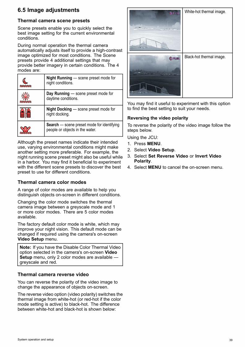
Thermal camera reverse videoYou can reverse the polarity of the video image tochange the appearance of objects on-screen.The reverse video option (video polarity) switches thethermal image from white-hot (or red-hot if the colormode setting is active) to black-hot. The differencebetween white-hot and black-hot is shown below:
White-hot thermal image.
Black-hot thermal image.
You may find it useful to experiment with this optionto find the best setting to suit your needs.
Reversing the video polarityTo reverse the polarity of the video image follow thesteps below.Using the JCU:1. Press MENU.2. Select Video Setup.3. Select Set Reverse Video or Invert Video
Polarity.4. Select MENU to cancel the on-screen menu.
System operation and setup 39
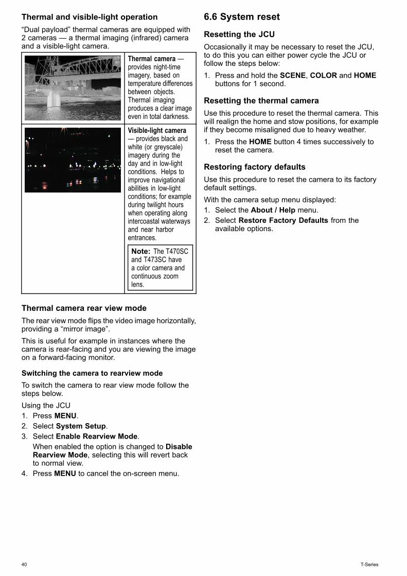
Thermal and visible-light operation“Dual payload” thermal cameras are equipped with2 cameras — a thermal imaging (infrared) cameraand a visible-light camera.
Thermal camera —provides night-timeimagery, based ontemperature differencesbetween objects.Thermal imagingproduces a clear imageeven in total darkness.
Visible-light camera— provides black andwhite (or greyscale)imagery during theday and in low-lightconditions. Helps toimprove navigationalabilities in low-lightconditions; for exampleduring twilight hourswhen operating alongintercoastal waterwaysand near harborentrances.
Note: The T470SCand T473SC havea color camera andcontinuous zoomlens.
Thermal camera rear view modeThe rear view mode flips the video image horizontally,providing a “mirror image”.This is useful for example in instances where thecamera is rear-facing and you are viewing the imageon a forward-facing monitor.
Switching the camera to rearview modeTo switch the camera to rear view mode follow thesteps below.Using the JCU1. Press MENU.2. Select System Setup.3. Select Enable Rearview Mode.
When enabled the option is changed to DisableRearview Mode, selecting this will revert backto normal view.
4. Press MENU to cancel the on-screen menu.
6.6 System reset
Resetting the JCUOccasionally it may be necessary to reset the JCU,to do this you can either power cycle the JCU orfollow the steps below:1. Press and hold the SCENE, COLOR and HOME
buttons for 1 second.
Resetting the thermal cameraUse this procedure to reset the thermal camera. Thiswill realign the home and stow positions, for exampleif they become misaligned due to heavy weather.1. Press the HOME button 4 times successively to
reset the camera.
Restoring factory defaultsUse this procedure to reset the camera to its factorydefault settings.With the camera setup menu displayed:1. Select the About / Help menu.2. Select Restore Factory Defaults from the
available options.
40 T-Series
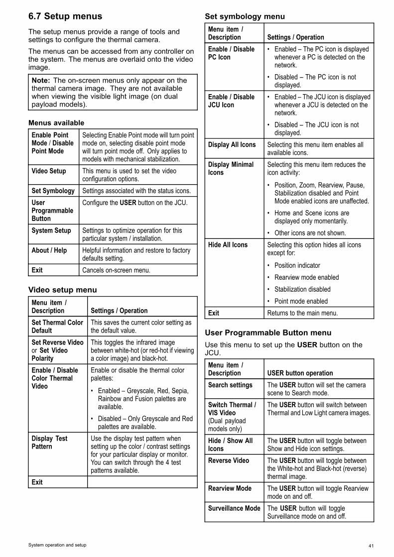
6.7 Setup menusThe setup menus provide a range of tools andsettings to configure the thermal camera.The menus can be accessed from any controller onthe system. The menus are overlaid onto the videoimage.
Note: The on-screen menus only appear on thethermal camera image. They are not availablewhen viewing the visible light image (on dualpayload models).
Menus availableEnable PointMode / DisablePoint Mode
Selecting Enable Point mode will turn pointmode on, selecting disable point modewill turn point mode off. Only applies tomodels with mechanical stabilization.
Video Setup This menu is used to set the videoconfiguration options.
Set Symbology Settings associated with the status icons.UserProgrammableButton
Configure the USER button on the JCU.
System Setup Settings to optimize operation for thisparticular system / installation.
About / Help Helpful information and restore to factorydefaults setting.
Exit Cancels on-screen menu.
Video setup menuMenu item /Description Settings / OperationSet Thermal ColorDefault
This saves the current color setting asthe default value.
Set Reverse Videoor Set VideoPolarity
This toggles the infrared imagebetween white-hot (or red-hot if viewinga color image) and black-hot.
Enable / DisableColor ThermalVideo
Enable or disable the thermal colorpalettes:
• Enabled – Greyscale, Red, Sepia,Rainbow and Fusion palettes areavailable.
• Disabled – Only Greyscale and Redpalettes are available.
Display TestPattern
Use the display test pattern whensetting up the color / contrast settingsfor your particular display or monitor.You can switch through the 4 testpatterns available.
Exit
Set symbology menuMenu item /Description Settings / OperationEnable / DisablePC Icon
• Enabled – The PC icon is displayedwhenever a PC is detected on thenetwork.
• Disabled – The PC icon is notdisplayed.
Enable / DisableJCU Icon
• Enabled – The JCU icon is displayedwhenever a JCU is detected on thenetwork.
• Disabled – The JCU icon is notdisplayed.
Display All Icons Selecting this menu item enables allavailable icons.
Display MinimalIcons
Selecting this menu item reduces theicon activity:
• Position, Zoom, Rearview, Pause,Stabilization disabled and PointMode enabled icons are unaffected.
• Home and Scene icons aredisplayed only momentarily.
• Other icons are not shown.Hide All Icons Selecting this option hides all icons
except for:
• Position indicator• Rearview mode enabled• Stabilization disabled• Point mode enabled
Exit Returns to the main menu.
User Programmable Button menuUse this menu to set up the USER button on theJCU.
Menu item /Description USER button operationSearch settings The USER button will set the camera
scene to Search mode.Switch Thermal /VIS Video(Dual payloadmodels only)
The USER button will switch betweenThermal and Low Light camera images.
Hide / Show AllIcons
The USER button will toggle betweenShow and Hide icon settings.
Reverse Video The USER button will toggle betweenthe White-hot and Black-hot (reverse)thermal image.
Rearview Mode The USER button will toggle Rearviewmode on and off.
Surveillance Mode The USER button will toggleSurveillance mode on and off.
System operation and setup 41
Menu item /Description USER button operationPoint Mode The USER button will toggle Point
Mode on and off.Exit Returns to the main menu.
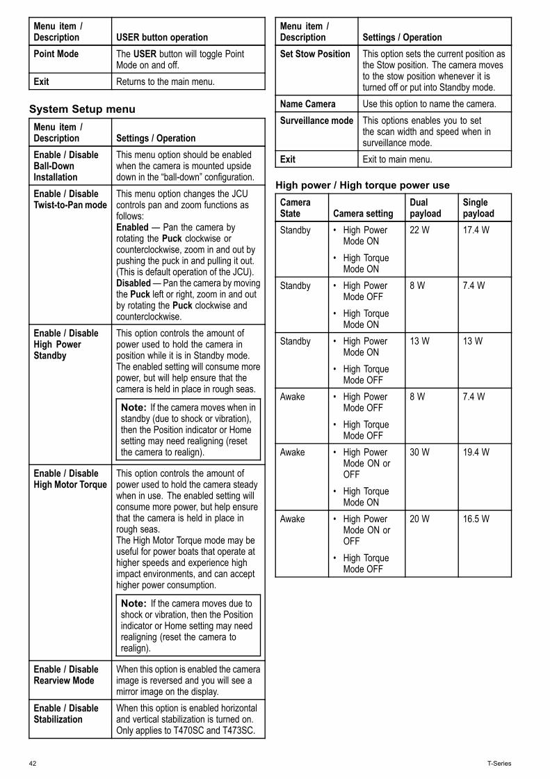
System Setup menuMenu item /Description Settings / OperationEnable / DisableBall-DownInstallation
This menu option should be enabledwhen the camera is mounted upsidedown in the “ball-down” configuration.
Enable / DisableTwist-to-Pan mode
This menu option changes the JCUcontrols pan and zoom functions asfollows:Enabled — Pan the camera byrotating the Puck clockwise orcounterclockwise, zoom in and out bypushing the puck in and pulling it out.(This is default operation of the JCU).Disabled—Pan the camera by movingthe Puck left or right, zoom in and outby rotating the Puck clockwise andcounterclockwise.
Enable / DisableHigh PowerStandby
This option controls the amount ofpower used to hold the camera inposition while it is in Standby mode.The enabled setting will consume morepower, but will help ensure that thecamera is held in place in rough seas.
Note: If the camera moves when instandby (due to shock or vibration),then the Position indicator or Homesetting may need realigning (resetthe camera to realign).
Enable / DisableHigh Motor Torque
This option controls the amount ofpower used to hold the camera steadywhen in use. The enabled setting willconsume more power, but help ensurethat the camera is held in place inrough seas.The High Motor Torque mode may beuseful for power boats that operate athigher speeds and experience highimpact environments, and can accepthigher power consumption.
Note: If the camera moves due toshock or vibration, then the Positionindicator or Home setting may needrealigning (reset the camera torealign).
Enable / DisableRearview Mode
When this option is enabled the cameraimage is reversed and you will see amirror image on the display.
Enable / DisableStabilization
When this option is enabled horizontaland vertical stabilization is turned on.Only applies to T470SC and T473SC.
Menu item /Description Settings / OperationSet Stow Position This option sets the current position as
the Stow position. The camera movesto the stow position whenever it isturned off or put into Standby mode.
Name Camera Use this option to name the camera.Surveillance mode This options enables you to set
the scan width and speed when insurveillance mode.
Exit Exit to main menu.
High power / High torque power useCameraState Camera setting
Dualpayload
Singlepayload
Standby • High PowerMode ON
• High TorqueMode ON
22 W 17.4 W
Standby • High PowerMode OFF
• High TorqueMode ON
8 W 7.4 W
Standby • High PowerMode ON
• High TorqueMode OFF
13 W 13 W
Awake • High PowerMode OFF
• High TorqueMode OFF
8 W 7.4 W
Awake • High PowerMode ON orOFF
• High TorqueMode ON
30 W 19.4 W
Awake • High PowerMode ON orOFF
• High TorqueMode OFF
20 W 16.5 W
42 T-Series
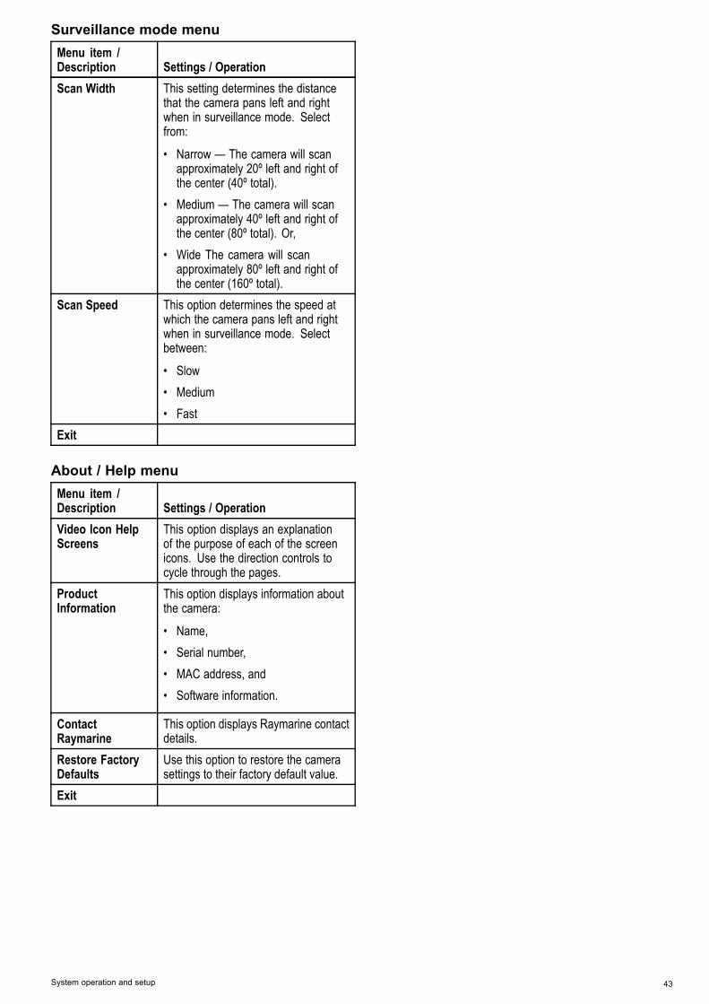
Surveillance mode menuMenu item /Description Settings / OperationScan Width This setting determines the distance
that the camera pans left and rightwhen in surveillance mode. Selectfrom:
• Narrow — The camera will scanapproximately 20º left and right ofthe center (40º total).
• Medium — The camera will scanapproximately 40º left and right ofthe center (80º total). Or,
• Wide The camera will scanapproximately 80º left and right ofthe center (160º total).
Scan Speed This option determines the speed atwhich the camera pans left and rightwhen in surveillance mode. Selectbetween:
• Slow• Medium• Fast
Exit
About / Help menuMenu item /Description Settings / OperationVideo Icon HelpScreens
This option displays an explanationof the purpose of each of the screenicons. Use the direction controls tocycle through the pages.
ProductInformation
This option displays information aboutthe camera:
• Name,• Serial number,• MAC address, and• Software information.
ContactRaymarine
This option displays Raymarine contactdetails.
Restore FactoryDefaults
Use this option to restore the camerasettings to their factory default value.
Exit
System operation and setup 43

44 T-Series

Chapter 7: Troubleshooting and support
Chapter contents• 7.1 Thermal camera troubleshooting on page 46• 7.2 Raymarine customer support on page 48
Troubleshooting and support 45
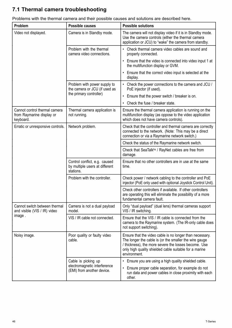
7.1 Thermal camera troubleshootingProblems with the thermal camera and their possible causes and solutions are described here.
Problem Possible causes Possible solutionsCamera is in Standby mode. The camera will not display video if it is in Standby mode.
Use the camera controls (either the thermal cameraapplication or JCU) to “wake” the camera from standby.
Problem with the thermalcamera video connections.
• Check thermal camera video cables are sound andproperly connected.
• Ensure that the video is connected into video input 1 atthe multifunction display or GVM.
• Ensure that the correct video input is selected at thedisplay.
Video not displayed.
Problem with power supply tothe camera or JCU (if used asthe primary controller)
• Check the power connections to the camera and JCU /PoE injector (if used).
• Ensure that the power switch / breaker is on.• Check the fuse / breaker state.
Cannot control thermal camerafrom Raymarine display orkeyboard.
Thermal camera application isnot running.
Ensure the thermal camera application is running on themultifunction display (as oppose to the video applicationwhich does not have camera controls).Check that the controller and thermal camera are correctlyconnected to the network. (Note: This may be a directconnection or via a Raymarine network switch.)Check the status of the Raymarine network switch.
Network problem.
Check that SeaTalkhs / RayNet cables are free fromdamage.
Control conflict, e.g. causedby multiple users at differentstations.
Ensure that no other controllers are in use at the sametime.
Check power / network cabling to the controller and PoEinjector (PoE only used with optional Joystick Control Unit).
Erratic or unresponsive controls.
Problem with the controller.
Check other controllers if available. If other controllersare operating this will eliminate the possibility of a morefundamental camera fault.
Camera is not a dual payloadmodel.
Only “dual payload” (dual lens) thermal cameras supportVIS / IR switching.
Cannot switch between thermaland visible (VIS / IR) videoimage . VIS / IR cable not connected. Ensure that the VIS / IR cable is connected from the
camera to the Raymarine system. (The IR-only cable doesnot support switching).
Poor quality or faulty videocable.
Ensure that the video cable is no longer than necessary.The longer the cable is (or the smaller the wire gauge/ thickness), the more severe the losses become. Useonly high quality shielded cable suitable for a marineenvironment.
Noisy image.
Cable is picking upelectromagnetic interference(EMI) from another device.
• Ensure you are using a high quality shielded cable.• Ensure proper cable separation, for example do not
run data and power cables in close proximity with eachother.
46 T-Series
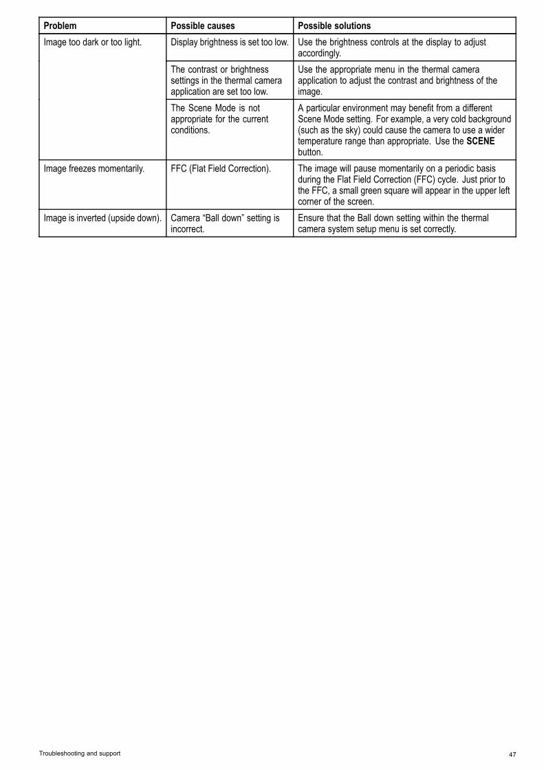
Problem Possible causes Possible solutionsDisplay brightness is set too low. Use the brightness controls at the display to adjust
accordingly.The contrast or brightnesssettings in the thermal cameraapplication are set too low.
Use the appropriate menu in the thermal cameraapplication to adjust the contrast and brightness of theimage.
Image too dark or too light.
The Scene Mode is notappropriate for the currentconditions.
A particular environment may benefit from a differentScene Mode setting. For example, a very cold background(such as the sky) could cause the camera to use a widertemperature range than appropriate. Use the SCENEbutton.
Image freezes momentarily. FFC (Flat Field Correction). The image will pause momentarily on a periodic basisduring the Flat Field Correction (FFC) cycle. Just prior tothe FFC, a small green square will appear in the upper leftcorner of the screen.
Image is inverted (upside down). Camera “Ball down” setting isincorrect.
Ensure that the Ball down setting within the thermalcamera system setup menu is set correctly.
Troubleshooting and support 47

7.2 Raymarine customer supportRaymarine provides a comprehensive customersupport service. You can contact customer supportthrough the Raymarine website, telephone ande-mail. If you are unable to resolve a problem, pleaseuse any of these facilities to obtain additional help.
Web supportPlease visit the customer support area of our websiteat:www.raymarine.comThis contains Frequently Asked Questions, servicinginformation, e-mail access to the RaymarineTechnical Support Department and details ofworldwide Raymarine agents.
Telephone and e-mail supportIn the USA:• Tel: +1 603 324 7900• Toll Free: +1 800 539 5539• E-mail: [email protected] the UK, Europe, and the Middle East:• Tel: +44 (0)13 2924 6777• E-mail: [email protected] Southeast Asia and Australia:• Tel: +61 (0)29479 4800• E-mail: [email protected]
Product informationIf you need to request service, please have thefollowing information to hand:• Product name.• Product identity.• Serial number.• Software application version.• System diagrams.You can obtain this product information using themenus within your product.
48 T-Series

Chapter 8: Technical specification
Chapter contents• 8.1 Technical specification on page 50
Technical specification 49
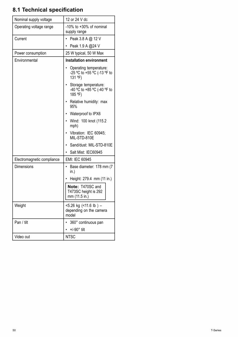
8.1 Technical specificationNominal supply voltage 12 or 24 V dcOperating voltage range -10% to +30% of nominal
supply rangeCurrent • Peak 3.8 A @ 12 V
• Peak 1.9 A @24 VPower consumption 25 W typical, 50 W MaxEnvironmental Installation environment
• Operating temperature:-25 ºC to +55 ºC (-13 ºF to131 ºF)
• Storage temperature:-40 ºC to +85 ºC (-40 ºF to185 ºF)
• Relative humidity: max95%
• Waterproof to IPX6• Wind: 100 knot (115.2
mph)• Vibration: IEC 60945;
MIL-STD-810E• Sand/dust: MIL-STD-810E• Salt Mist: IEC60945
Electromagnetic compliance EMI: IEC 60945Dimensions • Base diameter: 178 mm (7
in.)• Height: 279.4 mm (11 in.)
Note: T470SC andT473SC height is 292mm (11.5 in.)
Weight <5.26 kg (<11.6 lb ) –depending on the cameramodel
Pan / tilt • 360° continuous pan• +/-90° tilt
Video out NTSC
50 T-Series


www.raymarine.com