t type sq - schoeck.com
TRANSCRIPT

51
Schöck Isokorb® T type SQSuitable for supported steel balconies and canopies. It transfers positive shear forces.
Schöck Isokorb® T type SQ
Schöck Isokorb® T type SQ
TI Schöck Isokorb® for steel structures/GB/2020.1/May
Tty
pe S
QSt
eel –
rein
forc
ed co
ncre
te


53
Pillar Pillar Pillar Pillar
52: Schöck Isokorb® T type SQ: Pillar supported balconyFig.
SlabBalcony
Pillar
53: Schöck Isokorb® T type SQ: Connection to reinforced concrete inner slab; insulating element within the core insulation zone.Fig.
SlabBalcony
Pillar
54: Schöck Isokorb® T type SQ: Insulating element within the core insu-lation zone; steel stub adjuster between the Isokorb® and the balcony for flexible construction workflows
Fig.
Pillar
Balcony
Wall
55: Schöck Isokorb® T Type SQ-WU: Special design; required for the con-nection to a reinforced concrete wallFig.
SlabBalcony
Pillar
56: Schöck Isokorb® T type SQ: Steel stub adjuster between the Isokorb® and the balcony supports flexible construction workflowsFig.
Pillar
SlabBalcony
57: Schöck Isokorb® T type SQ: Connection of the steel member to an adapter that equalises the thickness of the outer insulationFig.
Element arrangement | Installation cross sections
Schöck Isokorb® T type SQ
TI Schöck Isokorb® for steel structures/GB/2020.1/May
Tty
pe S
QSt
eel –
rein
forc
ed co
ncre
te

54
Schöck Isokorb® modelType
Main load-bearing levelFire protection
Insulating element thicknessIsokorb® height
Insulating element lengthDiameter
Generation
T TypeSQ- V3 -RO-X80-H200- L180 - D16 -1.0
x
y
z
VRd,y
VRd,z
58: Schöck Isokorb® T type SQ: Direction of internal forces and momentsFig.
Schöck Isokorb® T type SQ variantsThe con� guration of the Schöck Isokorb® T type SQ can be varied as follows:▶ Main load-bearing level:
Shear force level V1, V2, V3▶ Fire resistance class:
R0▶ Insulating element thickness:
X80 = 80 mm▶ Isokorb® Height:
According to approval H = 180 mm to H = 280 mm, graduated in 10-mm steps▶ Isokorb® length:
L180 = 180 mm▶ Thread diameter:
D16 = M16▶ Generation:
1.0
Type designations in planning documents
Special designsPlease contact the design support department if you have connections that are not possible with the standard product variants shown in this information (contact details on page 3).
Direction of forces
Product selection | Type designations | Special designs | Design force direction
Schöck Isokorb® T type SQ
TI Schöck Isokorb® for steel structures/GB/2020.1/May
Tty
pe S
QSt
eel –
rein
forc
ed co
ncre
te

55
Schöck Isokorb® T type SQ V1 V2 V3
Design values with VRd,z [kN/element]
Concrete strength class ≥ C20/25
30.9 48.3 69.6
VRd,y [kN/element]
±2.5 ±4.0 ±6.5
Isokorb® length [mm] 180 180 180
Shear force bars 2 ⌀ 8 2 ⌀ 10 2 ⌀ 12
Pressure bearing / compression bars 2 ⌀ 14 2 ⌀ 14 2 ⌀ 14
Thread M16 M16 M16
l
SlabBalcony
H min
59: Schöck Isokorb® T type SQ: Static systemFig.
Schöck Isokorb® T type SQ: DesignArea of application of the Schöck Isokorb® T type SQ covers � oor and balcony slab structures with predominantly static, evenly distributed live loads according to BS EN 1991-1-1/NA2 or NA 3. Static veri� cation is to be produced for the components connect-ing to both sides of the Isokorb®. All Isokorb® T type SQ variants can transfer positive shear forces parallel to the z axis. The Isoko-rb® type SK o� ers solutions for negative (lifting) shear forces.
Notes on design▶ Design values are taken in relation to the rear edge of the � xing plate.▶ When using an indirect bearing solution for the Schöck Isokorb® T type SQ, the structural engineer must provide evidence, in
particular, of the load transfer in the reinforced concrete component.▶ The nominal dimension cnom of the concrete cover as per BS EN 1992-1-1 (EC2), 4.4.1 and BS EN 1992-1-1/NA is 20 mm for inter-
nal areas.
Design
Schöck Isokorb® T type SQ
TI Schöck Isokorb® for steel structures/GB/2020.1/May
Tty
pe S
QSt
eel –
rein
forc
ed co
ncre
te

56
Slab
≤ e ≤ e + a
Pillar Pillar Pillar Pillar
type SQ type SQ type SQ type SQ
Expansion jointa
60: Schöck Isokorb® T type SQ: Maximum expansion joint spacing e and lateral overhang aFig.
Slots
61: Schöck Isokorb® T type SQ: Expansion joint detail to ensure move-ment during temperature expansionFig.
Schöck Isokorb® T type SQ V1 - V3
Maximum expansion joint spacing e e [m]
Insulating element thickness [mm] 80 5.7
Maximum expansion joint spacingExpansion joints must be provided in the external component. Changes in length due to temperature deformation are deter-mined by the maximum distance (e) from the centre of the outermost Schöck Isokorb® T type SQ. The balcony structure may overhang the outermost Schöck Isokorb® element. In the case of � xed points, such as corners, half the maximum distance (e) from the � xed point applies. The calculation of the permissible expansion joint spacing is based on a reinforced concrete balcony slab that is securely connected to the steel members. If design measures have been implemented to ensure there is movement between the balcony slab and the individual steel members, then only the distances of the non-moving connections are relevant, see detail.
Expansion joints▶ If the expansion joint detail permanently permits temperature conditioned displacements of the cross member of length a, the
expansion joint spacing may be extended to a maximum of e + a .
Expansion joint spacing
Schöck Isokorb® T type SQ
TI Schöck Isokorb® for steel structures/GB/2020.1/May
Tty
pe S
QSt
eel –
rein
forc
ed co
ncre
te

57
180
e Re R
62: Schöck Isokorb® T type SQ: Edge distancesFig.
≥ 65
≥ 65Inner slab edge
63: Schöck Isokorb® T type SQ: Edge distances at the outer corner with Isokorbs® arranged vertically to each other Fig.
Schöck Isokorb® T type SQ V1 V2 V3
Design values with Concrete strength class ≥ C20/25
Isokorb® height H [mm]
Edge distance eR
[mm] VRd,z [kN/element]
180 - 190 30 ≤ eR < 74
14,2 20,4 28,5200 - 210 30 ≤ eR < 81
220 - 230 30 ≤ eR < 88
240 - 280 30 ≤ eR < 95
180 - 190 eR ≥ 74
No reduction required200 - 210 eR ≥ 81
220 - 230 eR ≥ 88
240 - 280 eR ≥ 95
Acceptable shear force VRd,zdepending on the edge distance
Edge spacingThe Schöck Isokorb® T type SQ must be so positioned that minimum edge distances related to the inner reinforced concrete struc-tural element are maintained:
Edge distances▶ Edge distances eR < 30 mm are not permitted!▶ If two Isokorb® T type SQ are arranged vertically to each other at a corner. edge distances e ≥ 65 mm are required.
Edge spacing
Schöck Isokorb® T type SQ
TI Schöck Isokorb® for steel structures/GB/2020.1/May
Tty
pe S
QSt
eel –
rein
forc
ed co
ncre
te

58
e A
64: Schöck Isokorb® T type SQ: Centre-to-centre distanceFig.
Schöck Isokorb® T type SQ V1 - V3
Design values with Concrete strength class ≥ C20/25
Isokorb® height H [mm]
Centre-to-centre distance eA [mm] VRd,z [kN/element]
180 - 190 eA ≥ 230
No reduction required200 - 210 eA ≥ 245
220 - 230 eA ≥ 255
240 - 280 eA ≥ 270
Design internal forces depending on the centre-to-centre distance
Centre-to-centre distancesThe Schöck Isokorb® T type SQ must be so positioned that minimum centre-to-centre distances of Isokorb® to Isokorb® are main-tained:
Centre-to-centre distances▶ With the exceeding of the axis distance eA the load-bearing capacity of the type SQ is to be reduced.▶ Please contact the design support department at Schöck for the reduced design values. Contact see page 3.
Centre-to-centre distances
Schöck Isokorb® T type SQ
TI Schöck Isokorb® for steel structures/GB/2020.1/May
Tty
pe S
QSt
eel –
rein
forc
ed co
ncre
te
59
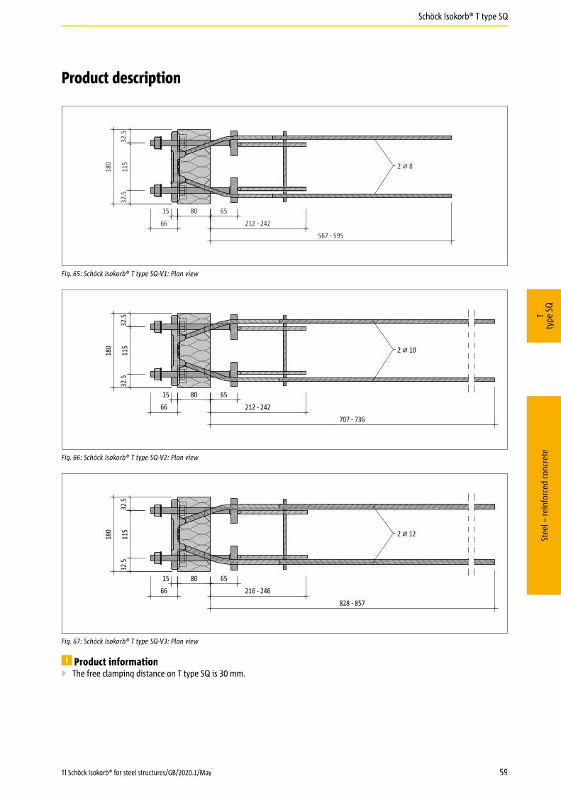
115
180
15 80 65
66
567 - 595
212 - 242
32.5
32.5
2 ⌀ 8
65: Schöck Isokorb® T type SQ-V1: Plan viewFig.
115
180
15 80 65
66
707 - 736
212 - 242
2 ⌀ 10
32.5
32.5
66: Schöck Isokorb® T type SQ-V2: Plan viewFig.
115
180
15 80
66
828 - 857
65
216 - 246
2 ⌀ 12
32.5
32.5
67: Schöck Isokorb® T type SQ-V3: Plan viewFig.
Product information▶ The free clamping distance on T type SQ is 30 mm.
Product description
Schöck Isokorb® T type SQ
TI Schöck Isokorb® for steel structures/GB/2020.1/May
Tty
pe S
QSt
eel –
rein
forc
ed co
ncre
te

1155
40
180
- 280
15 80 65
6620
16
1155
40
180
- 280
15 80 65
66
20
16
1155
40
180
- 280
15 80 65
66
20
16
60
68: Schöck Isokorb® T type SQ-V1: Cross section of the productFig.
69: Schöck Isokorb® T type SQ-V2: Cross section of the productFig.
70: Schöck Isokorb® T type SQ-V3: Cross section of the productFig.
Product information▶ The free clamping distance on T type SQ is 30 mm.
Product description
Schöck Isokorb® T type SQ
TI Schöck Isokorb® for steel structures/GB/2020.1/May
Tty
pe S
QSt
eel –
rein
forc
ed co
ncre
te

Pos. ①
Pos. ①
61
71: Schöck Isokorb® T type SQ: On-site reinforcement: Cross sectionFig.
72: Schöck Isokorb® T type SQ: On-site reinforcement: Plan viewFig.
Schöck Isokorb® T type SQ V1 - V3
On-site reinforce-ment Type of bearing Height H [mm] Floor slab (XC1) concrete grade ≥ C25/30
Balcony steel structure
Pos. 1 Edge and splitting tension reinforcement
Pos. 1 direct/indirect 180 - 280 included with the product
Schöck Isokorb® T type SQ
Information about on-site reinforcement▶ The straight legs of the shear force rods must be lapped to the reinforced concrete slab reinforcement. The lap lengths must
comply with BS EN 1992-1-1 (EC2), Section 8.4.
On-site reinforcement - In-situ concrete construction
Schöck Isokorb® T type SQ
TI Schöck Isokorb® for steel structures/GB/2020.1/May
Tty
pe S
QSt
eel –
rein
forc
ed co
ncre
te

≥ 100
Pos. ①
≥ 100 Pos. ①
62
73: Schöck Isokorb® T type SQ: On-site reinforcement for semi-precast construction: Cross sectionFig.
74: Schöck Isokorb® T type SQ: On-site reinforcement for semi-precast construction: Plan viewFig.
Schöck Isokorb® T type SQ V1 - V3
On-site reinforce-ment Type of bearing Height H [mm] Floor slab (XC1) concrete grade ≥ C25/30
Balcony steel structure
Pos. 1 Edge and splitting tension reinforcement
Pos. 1 direct/indirect 180 - 280 included with the product, alternative version with on-site stirrups 2 � H8
Schöck Isokorb® T type SQ
Information about on-site reinforcement▶ The straight legs of the shear force rods must be lapped to the reinforced concrete slab reinforcement. The lap lengths must
comply with BS EN 1992-1-1 (EC2), Section 8.4.▶ If composite pre-cast � ooring is being installed, the lower legs of the factory-supplied links can be shortened on site and re-
placed with two suitable ⌀8 stirrups.
On-site reinforcement - Precast construction
Schöck Isokorb® T type SQ
TI Schöck Isokorb® for steel structures/GB/2020.1/May
Tty
pe S
QSt
eel –
rein
forc
ed co
ncre
te

63
115 15
6
6
120
18
26
28 (
38)
1740
115
H - 4
0
40
4
4 42 x M16
4
4
Weld tight Weld tight
t1 ≤ t ≤ 30
32.5 32.5
75: Schöck Isokorb® T type SQ: Design of the fixing plate connectionFig.
T Type SQ for transferring positive shear forces
The choice of � xing plate thickness t is determined by the minimum thickness t1 as speci� ed by the structural engineer. This thick-ness must not, however, be greater than the clamping distance of the Schöck Isokorb® T type SQ, which is 30 mm.
Fixing Plate▶ The illustrated elongated holes allow an uplifting of the endplate of up to 10 mm. The values shown in brackets allow for the
increase of the tolerances of up to 20 mm.▶ If horizontal forces VEd,y > 0,342 � min. VEd,z parallel to the insulation joint occur, the front slab must be modi� ed with ⌀18 mm
round holes instead of slots to ensure load transfer.▶ The structural engineer must specify the overall dimensions of the � xing plate▶ The construction drawing must contain the tightening torque for the nuts, which is speci� ed as follows:
T type SQ (threaded rod ⌀ 16): Mr = 50 Nm▶ The Schöck Isokorb® embedded in concrete are to be measured in-situ before the front slabs are produced.
Fixing Plate
Schöck Isokorb® T type SQ
TI Schöck Isokorb® for steel structures/GB/2020.1/May
Tty
pe S
QSt
eel –
rein
forc
ed co
ncre
te

64
On-site butt stopThe on-site butt stop is absolutely crucial for transferring shear forces from the on-site front slab to the Isokorb® T type SQ! The spacer shims supplied by Schöck are used for vertical adjustment between butt stop and Schöck Isokorb®.
40
15
On-site butt stop
76: Schöck Isokorb® T type SQ: Mounting the steel memberFig.
Spacer shim
Load plate
On-site butt stop
Shear force
77: Schöck Isokorb® T type SQ: On-site butt stop for transferring shear forcesFig.
On-site butt stop▶ Type of steel to match static requirements.▶ Apply corrosion protection after welding.▶ Steel construction: Checking for dimensional inaccuracy of the structure prior to fabrication is absolutely essential!
Spacer shims▶ Details of dimensions and materials, see page 16▶ With installation ensure they are free from burrs and are even.
On-site butt stop
Schöck Isokorb® T type SQ
TI Schöck Isokorb® for steel structures/GB/2020.1/May
Tty
pe S
QSt
eel –
rein
forc
ed co
ncre
te

65
4 SlabBalcony
78: Schöck Isokorb® T type SQ: Continuous support neededFig.
Supported balconyThe Schöck Isokorb T Type SQ is developed for supported balconies. It transfers exclusively shear forces, no bending moments.
Hazard warning - missing supports▶ The balcony will collapse if not supported.▶ At all stages of construction, the balcony must be supported with statically suitable pillars or supports.▶ Even when completed, the balcony must be supported with statically suitable pillars or supports.▶ A removal of the temporary supports is permitted only after the installation of the � nal support.
Type of bearing: supported
Schöck Isokorb® T type SQ
TI Schöck Isokorb® for steel structures/GB/2020.1/May
Tty
pe S
QSt
eel –
rein
forc
ed co
ncre
te

2
4
3A 3B
3C 3D
1 5
6
7
39 mm
66
Method statement for concrete frame contractor
Schöck Isokorb® T type SQ
TI Schöck Isokorb® for steel structures/GB/2020.1/May
Tty
pe S
QSt
eel –
rein
forc
ed co
ncre
te

11
8
9
10
12
14
13
D16: Mr = 50 Nm
67
Method statement for steel constructor
Schöck Isokorb® T type SQ
TI Schöck Isokorb® for steel structures/GB/2020.1/May
Tty
pe S
QSt
eel –
rein
forc
ed co
ncre
te

68
Check list for structural engineers
Has the right type of Schöck Isokorb® been selected for the static system? T Type SQ is a connection purely for shear forces (moment joint).
Have the loads on the Schöck Isokorb® connection been speci� ed at design level?
Have the � re protection requirements for the overall load-bearing structure been clari� ed? Are the on-site measures in-cluded in the construction drawings?
Does a connection to a wall or with height o� set necessitate the use of Isokorb® T type SQ-WU instead of T type SQ (see page 53) or another special design?
Are temperature deformations directly attributed to the Isokorb® connection and has the maximum expansion joint spac-ing been taken into consideration in this respect?
Is compliance with the conditions and dimensions of the on-site � xing plate assured?
Do the construction drawings contain su� cient reference to the essential on-site butt stop?
Has the cutout on the inner slab side been taken into account if using the Isokorb® T type SQ in precast element slabs?
Has reasonable agreement been reached between the concrete contractor and steel constructor with regard to the accura-cy of installation of the Isokorb® T type SQ?
Has the information about the required installation accuracy been incorporated into the concrete frame designs for the construction supervisor and the concrete contractor?
Are the tightening torques for the screwed connections noted in the construction drawings?
Check list for concrete contractor
Does a formwork concept exist for developing an on-site template for installing the Isokorb®?
Is Schöck’s installation aid required to ensure best possible correct sitting and alignment of the Isokorb®?
Are you in contact with the steel constructor to discuss the required accuracy of the Isokorb® installation?
Check list for steel constructors
Has the position of the installed Isokorb® in the building structure been measured to determine the height of the on-site butt stop?
Do the � xing plates of the adapters contain the necessary vertical/horizontal slots for on-site tolerance?
Is the on-site butt stop present on the � xing plate for connecting the steel member to the Isokorb®?
Has the gradient of the steel member been adjusted to incorporate the water drainage direction?
Has the necessary tightening moment for the nuts on the Isokorb® been taken into consideration?T type SQ-V2, T type SQ-V3 (M16 thread): Mr = 50 Nm
Check list
Schöck Isokorb® T type SQ
TI Schöck Isokorb® for steel structures/GB/2020.1/May
Tty
pe S
QSt
eel –
rein
forc
ed co
ncre
te