t1 fundamentals
TRANSCRIPT
Revision 1.0 01-23-97
1
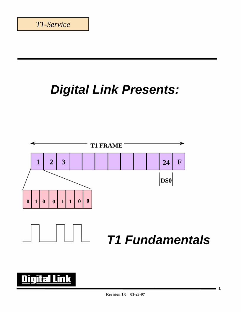
T1 FRAME
DS0
F1 2 3 24
Digital Link Presents:
T1 Fundamentals
T1-ServiceT1-Service
0 1 0 0 1 1 0 0
Revision 1.0 01-23-97
2
i Copyright © 1996, Digital Link Digital Link CorporationWorld copyright reserved. No part of this publication may be stored in a retrieval system,transmited, or reproduced in any way, including but not limited to photocopy, photograph,magnetic, chemical, or other record, without the prior agreement and written permission ofDigital Link Corporation.Digital Link Corporation 217 Humboldt Court Sunnyvale, California 94089 (408) 745-6200FAX (408) 745-6250
T1 Fundamentals

Revision 1.0 01-23-97
3
Course Objectives:
Upon completion of this course the student will be able to:
• Understand the basic T1 transmission concepts
• Understand how the T1 frame is constructed.• Discern the differences between ESF and SF framing formats.
• List the main benefits of the ESF framing format• Be able to accurately match ESF error events with their functions.• Understand how ESF registers are used in trouble isolation
• Describe T1 alarm states (Blue, Yellow, Red).• Understand the wiring that is used on T1 lines and cables that are
used.
• Define the coding methods used on T1 circuits (B8ZS and AMI)• Understand the differences between format and logic errors.• Understand T1 troubleshooting techniques and equipment
T1 Fundamentals
Revision 1.0 01-23-97
4
A T1 is a Time Division Multiplexed, full duplex, synchronous data transmission technique. It has anoperational line data rate of 1.544Mbps. Below is a list of general information that applies to a T1 line.
Time Division Multiplexing (TDM) is a means to carry multiple voice and data conversations across asingle line. It is a very reliable means of communications as it a allows time slots to be dedicated toeach conversation (be it voice, data, fax or video). On the other hand, it is inefficient since if only a fewtime slots are needed the unused time slots will be idle. This will be discussed further later.
Full duplex operation is a method of transmission that enables information to be both transmitted andreceived at the same time.
The aggregate speed of a T-1 is 1.544Mbps. Only 1.536Mbps is usable as 8kbps is used for overhead.
Fractional T-1 is supported by the telephone carriers as a method to reduce cost to their customers.Some customers don’t need to use all time slots on a T-1, so FT1 is a way to get greater efficiency usingTDM to pay only for the number of time slots you need.
DS1 is the tariffed service from the carriers. DS refers to Digital Signal and has references at differentlevels such as: DS0 (64Kbps), DS2(6Mbps) and DS3(45Mbps). It defines the type of service that thecustomer will receive, the costs and the signal format. T-1 is what the DS1 signal becomes when it isplaced on a “Terrestrial” line.
Concepts Behind T1Concepts Behind T1Concepts Behind T1
What is T1?
Revision 1.0 01-23-97
5
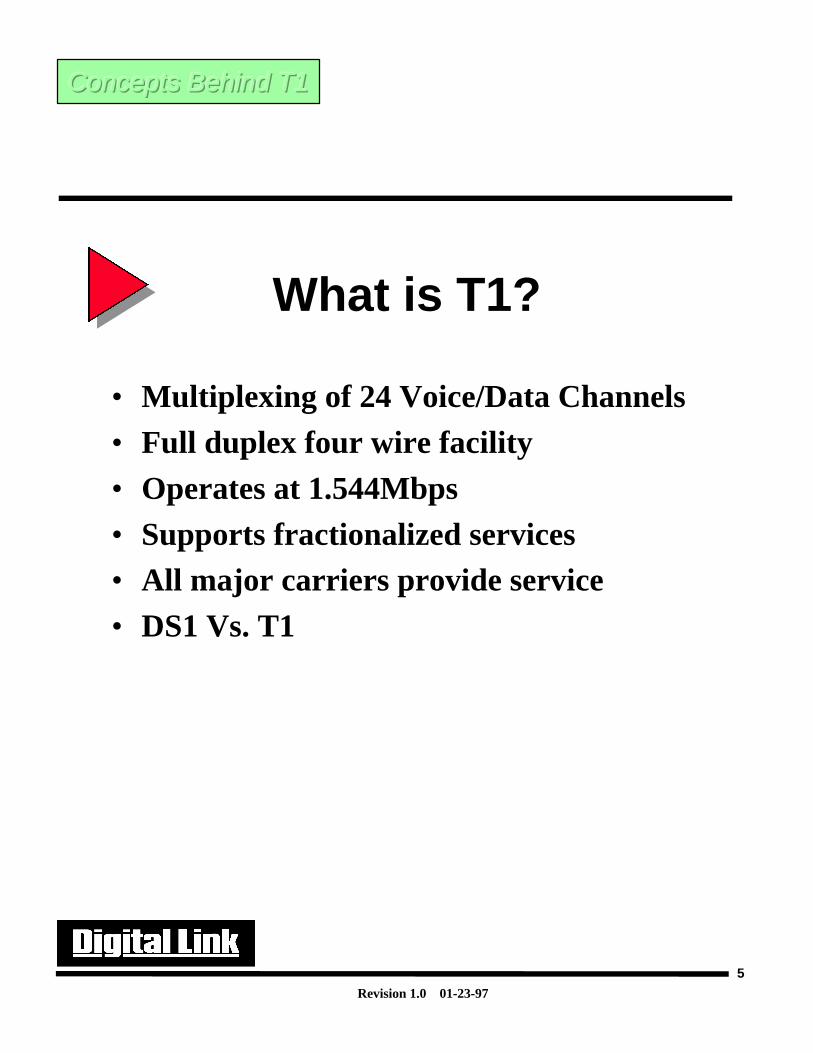
What is T1?
• Multiplexing of 24 Voice/Data Channels• Full duplex four wire facility• Operates at 1.544Mbps• Supports fractionalized services• All major carriers provide service• DS1 Vs. T1
Concepts Behind T1Concepts Behind T1Concepts Behind T1
Revision 1.0 01-23-97
6
T-1 Transmission Concepts
Nyquist Criterion-
Harry Nyquist discovered in the late 1920’s that in order to sample an analog signal so that it can berepresented in a digital format (and later be reconstructed back to it’s original form) that the analogsignal needs to be sampled at twice the highest frequency of the analog signal.
Since the average human speaks within the frequency range of 300-3300hz(cycles/sec), it wasdecided that the maximum frequency to represent a voice signal should be 4000hz. When we apply thisto the Nyquist’s theorem we discover that the minimum sampling rate necessary to digitize an analogsignal of 4000hz is 2X4000hz=8000hz=8000samples/sec.
PAM- When an analog signal is sent through a sampler device it will create a digital waveform with varyingamplitudes. The digital waveform that is created has gone through a process called pulse amplitudemodulation.
PAM takes amplitude values of the analog signals during the sampling period. As there is no suchthing as a true impulse function to sample the signal, the original analog signal at this stage would lookas if someone had taken snap shots of it at particular instances of time.
Concepts Behind T1Concepts Behind T1Concepts Behind T1
Revision 1.0 01-23-97
7
T-1 Transmission Concepts
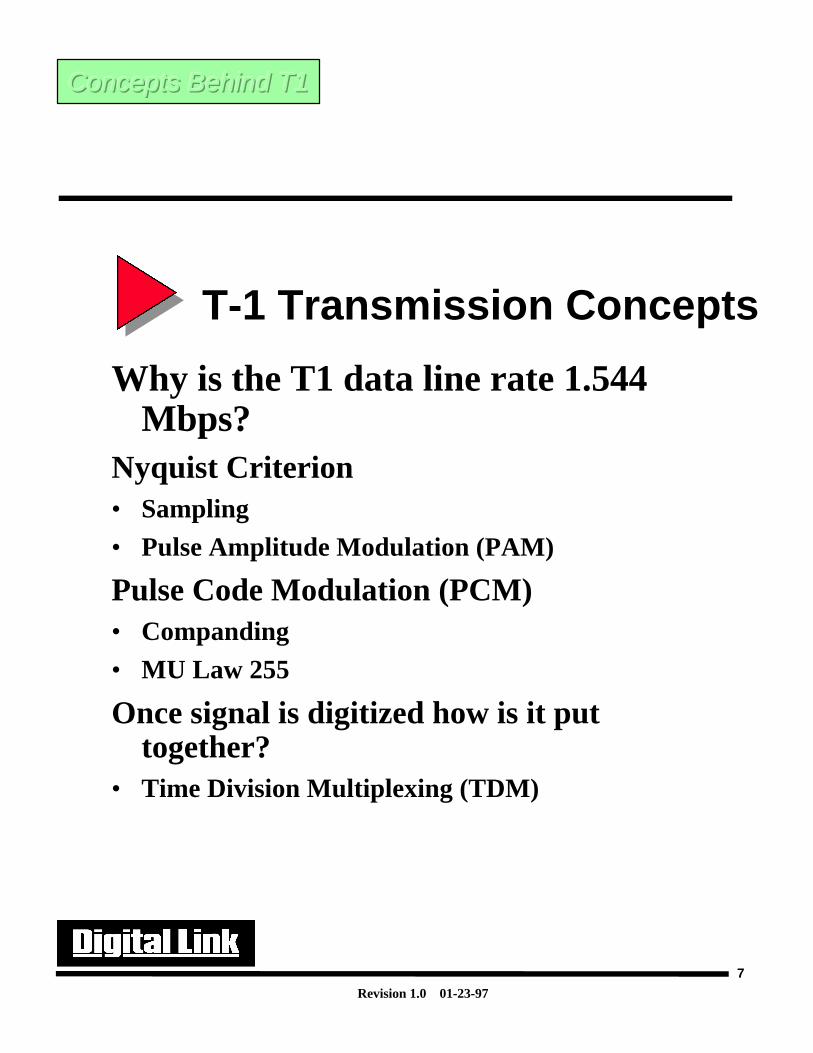
Why is the T1 data line rate 1.544Mbps?
Nyquist Criterion• Sampling
• Pulse Amplitude Modulation (PAM)
Pulse Code Modulation (PCM)• Companding
• MU Law 255
Once signal is digitized how is it puttogether?
• Time Division Multiplexing (TDM)
Concepts Behind T1Concepts Behind T1Concepts Behind T1
Revision 1.0 01-23-97
8
Analog To Digital Conversion
Quantizing- Quantization is the process in which ranges of values will be grouped together into a single value.This process would be similar to counting from 1 to 10. Once you start counting most people will chosequantized unit increments, unless specified otherwise. This is because there are an infinite number ofvalues between 1 and 10. We could say that anything from 0 to 1is a value of 1, and anything greaterthat 1 but less than or equal to 2 is a value of 2 and so on up to 10. This would be a form ofquantization.
Experiments have shown that in order to reproduce a voice signal, of good quality, that there must be2048 uniform quantized levels. This equates to 11 bits of resolution(or dynamic range). To reduce thenumber of quantum steps, the analog signal is compressed prior to coding. Compression isaccomplished through a technique called companding. Companding is based upon the MU-law. This isexplained on the next page.
Concepts Behind T1Concepts Behind T1Concepts Behind T1
Revision 1.0 01-23-97
9
Analog To Digital Conversion
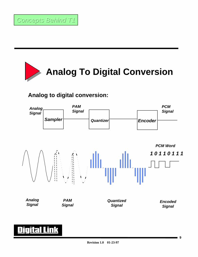
Analog to digital conversion:
Sampler
PAMSignal
Encoder
AnalogSignal
PCM Signal
Quantizer
AnalogSignal
1 0 1 1 0 1 1 1
PCM Word
PAMSignal
QuantizedSignal
EncodedSignal
Concepts Behind T1Concepts Behind T1Concepts Behind T1
Revision 1.0 01-23-97
10
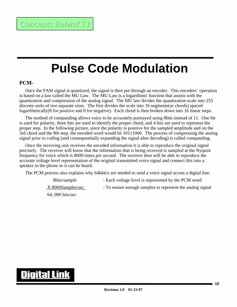
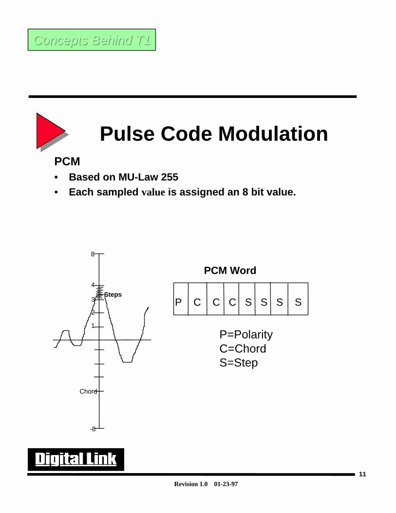
Pulse Code ModulationPCM- Once the PAM signal is quantized, the signal is then put through an encoder. This encoders’ operationis based on a law called the MU Law. The MU Law is a logarithmic function that assists with thequantization and compression of the analog signal. The MU law divides the quantization scale into 255discrete units of two separate sizes. The first divides the scale into 16 segments(or chords) spacedlogarithmically(8 for positive and 8 for negative). Each chord is then broken down into 16 linear steps.
The method of companding allows voice to be accurately portrayed using 8bits instead of 11. One bitis used for polarity, three bits are used to identify the proper chord, and 4 bits are used to represent theproper step. In the following picture, since the polarity is positive for the sampled amplitude and on the3rd chord and the 8th step, the encoded word would be 10111000. The process of compressing the analogsignal prior to coding (and consequentially expanding the signal after decoding) is called companding.
Once the receiving unit receives the encoded information it is able to reproduce the original signalprecisely. The receiver will know that the information that is being received is sampled at the Nyquistfrequency for voice which is 8000 times per second. The receiver then will be able to reproduce theaccurate voltage level representation of the original transmitted voice signal and connect this into aspeaker in the phone so it can be heard.
The PCM process also explains why 64kbit/s are needed to send a voice signal across a digital line.
8bits/sample - Each voltage level is represented by the PCM word
X 8000Samples/sec - To ensure enough samples to represent the analog signal
64, 000 bits/sec
Concepts Behind T1Concepts Behind T1Concepts Behind T1
Revision 1.0 01-23-97
11
Pulse Code ModulationPCM• Based on MU-Law 255• Each sampled value is assigned an 8 bit value.
Steps
1
2
3
4
8
-8
Chord
P C C C S S S S
PCM Word
P=PolarityC=ChordS=Step
Concepts Behind T1Concepts Behind T1Concepts Behind T1
Revision 1.0 01-23-97
12
Time Division MultiplexingTDM -The adjoining figure is a good example of how voice and data can share the same physical medium(i.e.wire, T1). A TDM mux will take samples of the incoming signals by port and allocate them into thecorrect time slots on the output. To do this there must be a way to tell where each time slot begins andwhere it ends. This is accomplished with the use of a framing bit that will allow the remote end unit tosynchronize to the local unit and thus be able to differentiate between time slots.
The US standards defined the DS1 service to allow 24 voice signals to go across a single line. Therefore24 time slots were selected to be used for the TDM mux. In the UK they use 32 time slots with only 30 foruse of data/voice.
There are also a few other ideas that go along with some of the concepts we have so far discussed.
• Channelized data- This is the ability to subdivide a higher transmission rate into multiple lower-ratechannels.
• Non Channelized data- This means that full T1 must be used.
• Channel Bank- A channel bank is a type of mux that can take an analog signal in on a single port,convert it to a digital signal, and put it out on a single time slot. A channel bank will have 24 ports andwill provide a completely channelized service. In the early days when there was not an adequate meansfor an end user to send data traffic across a digital line, they would run the data to a 9.6kbps modem(which has an analog output) and connect it to a channel bank port to get both Voice and Data on a singleline.
Concepts Behind T1Concepts Behind T1Concepts Behind T1

Revision 1.0 01-23-97
13
Time Division Multiplexing
Time Division Multiplexing (TDM)
MUX
TDM
1
2
3
4
5
24
. . . . . . . . . .F 24 9 8 7 6 5 4 3 2 1
Sample 1
Sample 2 . . .
8000
Key- D=Data V=Voice F=Frame
. . . . . . . . . .F 24 D V V
. . . . . . . . . .F 24 D V V
Concepts Behind T1Concepts Behind T1Concepts Behind T1
Revision 1.0 01-23-97
14
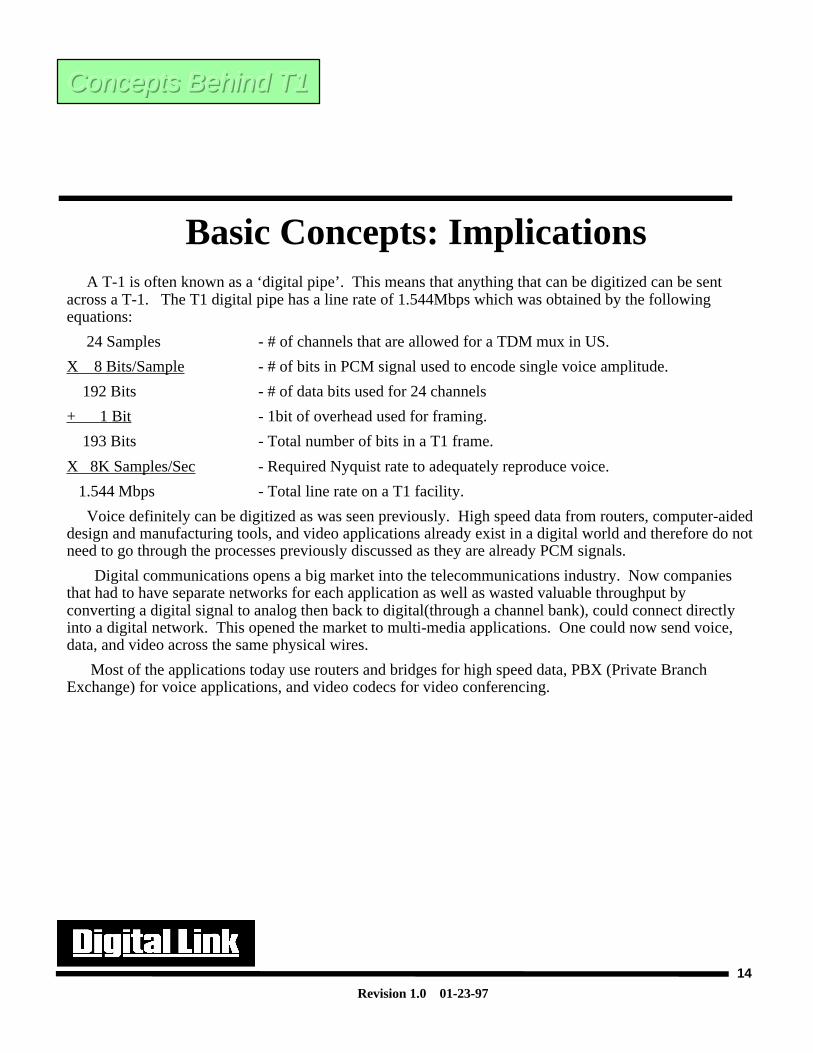
Basic Concepts: Implications A T-1 is often known as a ‘digital pipe’. This means that anything that can be digitized can be sentacross a T-1. The T1 digital pipe has a line rate of 1.544Mbps which was obtained by the followingequations:
24 Samples - # of channels that are allowed for a TDM mux in US.
X 8 Bits/Sample - # of bits in PCM signal used to encode single voice amplitude.
192 Bits - # of data bits used for 24 channels
+ 1 Bit - 1bit of overhead used for framing.
193 Bits - Total number of bits in a T1 frame.
X 8K Samples/Sec - Required Nyquist rate to adequately reproduce voice.
1.544 Mbps - Total line rate on a T1 facility.
Voice definitely can be digitized as was seen previously. High speed data from routers, computer-aideddesign and manufacturing tools, and video applications already exist in a digital world and therefore do notneed to go through the processes previously discussed as they are already PCM signals.
Digital communications opens a big market into the telecommunications industry. Now companiesthat had to have separate networks for each application as well as wasted valuable throughput byconverting a digital signal to analog then back to digital(through a channel bank), could connect directlyinto a digital network. This opened the market to multi-media applications. One could now send voice,data, and video across the same physical wires.
Most of the applications today use routers and bridges for high speed data, PBX (Private BranchExchange) for voice applications, and video codecs for video conferencing.
Concepts Behind T1Concepts Behind T1Concepts Behind T1
Revision 1.0 01-23-97
15
Basic Concepts: Implications
If something can be digitized, it can besent over the digital pipe (T-1)
• Voice
• High Speed Data
• CAD/CAM
• Video
Concepts Behind T1Concepts Behind T1Concepts Behind T1
Revision 1.0 01-23-97
16
History History History
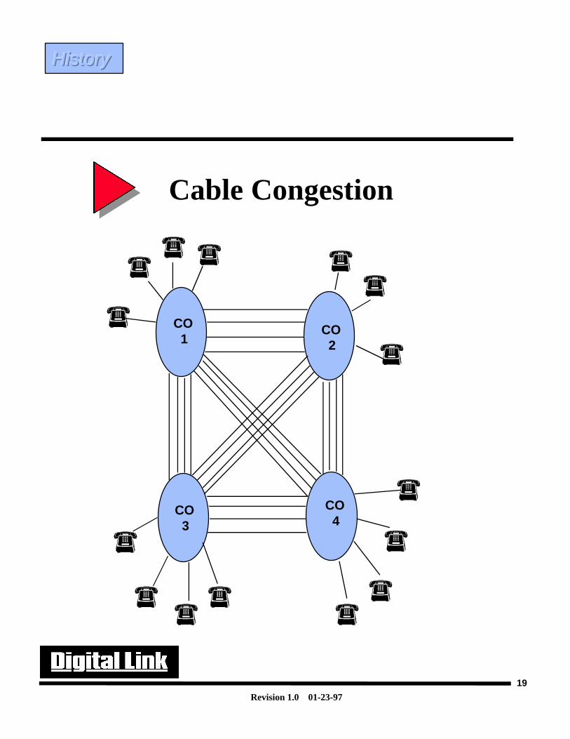
History of T1 AT&T introduced T1 technology in the early 1960’s to combat the growing problem of spacerestrictions between central offices(CO). Every time a new phone line was needed for a new customer,the telephone company would have to run a pair of wires not only to the new location, but also to thecentral office(if multiple phone lines in a disrict required more bandwidth). As a region started tobecome large enough to warrant its’ own local central office, new wires would need to be run betweenall the currently existing CO systems. The addition of a new CO would cause a geometric increase inthe number of wires that would be needed to run between offices. It became necessary to provide amore efficient system before all the cable conduits were filled to capacity and consequentially broughtthe existing system to its’ knees.
Another problem was signal quality. As an analog signal travels over a wire and gets amplified overand over again, it eventually will become extremely distorted. This is why, before the digital systemswere created, long distance calls would often sound very weak and distorted. Once the digital systemwas in place, regeneration of the signal was possible. Digital pulses are not just amplified, but arecompletely regenerated to their original form, thus increasing signal quality. The benefit of higherquality communications is what made networking of data communications equipment possible. Sincedata streams are just a string of 1’s and 0’s, if one bit out of a 1000 byte message is lost, the wholemessage will have to be re-transmitted.
Revision 1.0 01-23-97
17
History of T1
• Developed in early 1960’s.
• Offered as private facility service in late 1970’s to early ‘80’s
• Private T1 backbones driven by voice and decrease in T1 tariffs
• DACS-based Fractional T1 services in late 1980’s
History History History
Revision 1.0 01-23-97
18
In the beginning AT&T used T1 technology only between carrier offices. This where the cablingproblems were the worst. As was stated earlier every time a new area would become large enough for anew CO, new cables would have to be run to every CO in the area. Also, the cost of the T1 technologydidn’t make it pratical for public use, nor did the public as of yet have a great need for complete digitalnetwork to interconnect their systems (as computers were still relatively new).
Over time as the computer industry started booming, it became apparent that there was a need tointerconnect computer systems. Due to the low speed of the computers that were available in the early1970’s it was possible to carry digital signals from computers over analog lines with the use of modems.In 1983 telco companies started to offer private facility services to the T1 system. This was driven by agreat need to have reliable data communications and interconnections at higher rates as well as a decreasein T1 tariffs.
In the late 1980’s telco’s were offering DACS (Digital Access Cross-Connect Systems) services. Thesewere based upon the T1 services previously offered, but were more cost effective. As touched on earliertime division multiplexing is not efficient if one doesn’t need a full T1. The introduction of DACStechnology allowed the end user to pay for a full T1 only from the local CO to the local customerpremises. Between carrier offices the user would only have to pay for however many time slots hepurchased. The advantage of this is that the customer is able to pay a reduced monthly tariff as well as beable to expand the current services up to a full T1 data rate at a later date if needed.
Cable Congestion
History History History
Revision 1.0 01-23-97
19
Cable Congestion
CO 1
CO 2
CO 3
CO 4
History History History
Revision 1.0 01-23-97
20
Components of a T1Components of a T1Components of a T1
T-1 Issues When the T1 system was created there were many concerns that needed to be addressed. The firstwas how to construct the frame. Once the frame was built the next concern was how to format andmaintain synchronization between the T1 frames. The last issue was how to maintain synchronizationon the T1 line itself. AT&T stated in Pub 62411 that if more that 15 zeros were transmitted in a rowacross a T1, that there could be no guarantees regarding the integrity of the data and the timing used toextract it. Since a T1 line relies on it’s timing from the data itself, if a period of absence of signaloccurs, it would cause the network repeaters to ‘fall asleep’. This would cause timing slips in the signaland disrupt user data.
Alarms were also needed to be able to determine where problems were occurring. New definitionshad to be created to help isolate network problems on digital lines. The use of red, yellow and bluealarms assisted in discovering these problems.
Signaling also was involved. Since T1 was initially created for voice only, there was a need toprovide signaling information for phone information. Signaling is the method that phone informationsuch as Off hook, busy, etc. may be sent to the receiving switch or PBX so that phone calls can beplaced.
Revision 1.0 01-23-97
21
T-1 Issues
• Building the T-1 Frame
• Framing
• Formatting
• Signaling
• Line Coding
• Pulse Density
• Errors and Alarms
Components of a T1Components of a T1Components of a T1
Revision 1.0 01-23-97
22
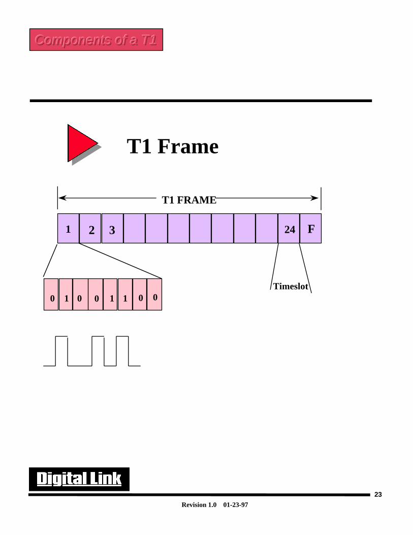
T1 FrameBuilding the T1 frame-
The T1 frame is represented by a composite of 24 separate DS0 channels, each representing a PCMencoded voice signal.( As previously discussed, each PCM encoded voice signal is represented using8bit encoding for the analog signal values.) Each channel is time division multiplexed in a round robinmethod to insure that each channel is transmitted in turn. To denote the beginning of each T1 frame aspecial bit is added. This bit is what differentiates D4 framing from ESF. More will be discussed aboutthis later.
Since each signal is sampled at 8000 times/sec, it can be seen that a T1 frame once sampled iscomprised of 24 64kb/s DSO’s (time slots or channels). When multiplied out this total comes to1.536Mb/s. This is what is referred to as the throughput of the T1 line. The framing bit which is alsosampled at 8000times/s will add an additional 8Kb/s to the T1 signal. Therefore stated clearly:
The line rate of a T1 is 1.544Mb/s, where 1.536Mb/s is the user actual throughput.
Components of a T1Components of a T1Components of a T1
Revision 1.0 01-23-97
23
T1 Frame
T1 FRAME
Timeslot
F1 2 3 24
0 1 0 0 1 1 0 0
Components of a T1Components of a T1Components of a T1
Revision 1.0 01-23-97
24
FramingFraming-
One of the more important features in T1 technology is the existence of framing. T1 framing isessential in providing synchronization of data across the T-span. The framing formats of T1s hasevolved significantly since the early 1960’s. Initially, frame formats were geared toward voice andanalog data only. The early formats (D1, D2, D1D, D3) were replaced with the advanced formats usedtoday, namely D4 and ESF.
D4, also referred to as SF or superframe, format relied on the use of 12 framing bits obtained bygrouping 12 T1 frames together into a ‘super frame’. These framing bits were used extensively forframe synchronization on the digital line. We will look into how this was accomplished a little later.
ESF, also referred to as extended super frame, format was created in the early 1980’s by AT&T.AT&T found that the SF format was lacking in particular areas of performance. ESF took the previousidea of grouping 12 frames together, and created the extended superframe to group 24 frames together.The expanded frame format allowed for greater error performance and analysis to be done on the T1lines without affecting user traffic.
Components of a T1Components of a T1Components of a T1
Revision 1.0 01-23-97
25
Framing
• D4 Super Frame
• ESF Extended Super Frame
• Signaling
Components of a T1Components of a T1Components of a T1
Revision 1.0 01-23-97
26
Framing: Super Frame (D4)
D4 Frame Format-
If we examine just the F bits or the 193rd bit of each T1 frame we will see that these bits form aunique pattern that repeats with every superframe. In this way the receivers can lock onto the framingpattern.
The way the receivers work is by first buffering 12 frames (2316 bits), then the receivers assume thatthe first bit is a frame bit. The receiver then counts 192 bits and looks at the next bit. Then another 192bits are counted and the 193rd bit is examined. The receiver will match its information to the patternshown in the following diagram. If the frame pattern isn’t reproduced, it assumes that the first bit wasnot the framing bit and moves onto the next one. This is done till all 192 bits are checked. Once theframe pattern is established the receivers will declare frame synchronization. Receivers have 50ms toresync once sync is lost (per AT&T 62411).
The synchronization bits are further split to provide two separate functions. One is to provideTerminal Framing (Ft) to identify the frame boundaries. The second purpose it to provide SignalFraming (Fs) to identify frame 6 and 12 in which signaling bits, A and B respectively, are transmittedwhen an application is channelized voice. Signaling will be discussed a later.
Note: All 8000 bits for framing are used to obtain synchronization.
Components of a T1Components of a T1Components of a T1

Revision 1.0 01-23-97
27
Framing: Super Frame (D4)
• Provides point of reference for each bit location
• Repetitive sequence permits synchronization
• Locates signals for voice communications
• Uses 8Kbps of the T-1 digital pipe
0
1
0
0
0
1
1
0
1
1
1
0
Components of a T1Components of a T1Components of a T1
Revision 1.0 01-23-97
28
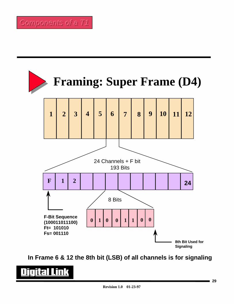
Framing: Super Frame (D4) D4 Framing Continued-
The adjoining diagram shows a detailed breakdown of the D4 framing structure. The 12 framestogether form a super frame. In the 6th and 12th frames of the super frame robbed bit signaling occurs.Robbed bit signaling robs the LSB(least significant bit) in every channel of the T1 frames six andtwelve. The PBX uses these bits to control functions that are used in the standard phone applications.These include picking up the receiver, dialing and hanging up the receiver. The 8th bit(LSB) in thePCM word in T1 frame 6 is designated as signaling type A. In the 12th frame the signaling bit is calledtype B. For extended superframe signaling type C and D will occur in the 18th and 24th frames. In thenext couple pages we will discuss these topics in greater detail.
Components of a T1Components of a T1Components of a T1
Revision 1.0 01-23-97
29
F 1 2
Framing: Super Frame (D4)
24 Channels + F bit 193 Bits
8 Bits
F-Bit Sequence(100011011100)Ft= 101010Fs= 001110
8th Bit Used forSignaling
121 2 3 4 5 6 7 8 9 10 11
In Frame 6 & 12 the 8th bit (LSB) of all channels is for signaling
24
0 1 0 0 1 1 0 0
Components of a T1Components of a T1Components of a T1
Revision 1.0 01-23-97
30
Framing: Signaling
Signaling- What are some of the characteristics found in the common phone? First off, to initiate a call, onewould pick up the receiver (go off hook) and listen for the ‘dial tone’. Digits are then entered toestablish a call to the receiving party. The receiving party’s phone will then ring or return a busy tone.When the call is completed one would place the receiver back in its cradle (go on hook) and the callwould now be complete.
Off hook, the dialing digits, the ringing or busy signal, and on hook are all components that arecommonly used in telephone conversations and are known as signaling elements. In environments thatuse channel banks or PBX’s for voice applications, signaling elements allow the phone system todetermine whether the incoming or outgoing calls are within the same company (DID- direct inwarddial) or out to the telephone company (DOD- direct outward dial). In order for signaling to berecognized it must take up space in the data channel. This is done by a process called robbed bitsignaling.
Robbed bit signaling will take the 8th bit of every time slot in frames 6 and 12 for D4 and frames6,12,18,24 in the ESF frame format. These bits are used to control the phone systems so that it willknow when a phone line is vacant or being used. Since each time slot represents a single phoneconversation, the bit robbing must occur in every time slot in the particular T1 frame. Frame 6 robbedbits are referred to as A bits. Frame 12, 18 and 24 (18 and 24 for ESF only) are referred to as B, C, andD bits respectively.
For voice applications, the robbing of bits in frame 6,12,18,24 are not of great importance in terms ofphone quality. Since the 8th bit of PCM words represents voltage or amplitude levels, the loss of theLSB (least significant bit) will not be able to be noticed by the end user.
For data communications traffic, the robbing of these bits would be fatal. However, since thesignaling bits are generated an removed by the channel bank, PBX or associated phone equipment, thedata traffic is not affected. If signaling were used on a data line, the actual throughput would have to bethrottled back to 56k (or 7 bit PCM words) per channel, yielding a T1 line rate of 1.344Mbps.
Components of a T1Components of a T1Components of a T1
Revision 1.0 01-23-97
31
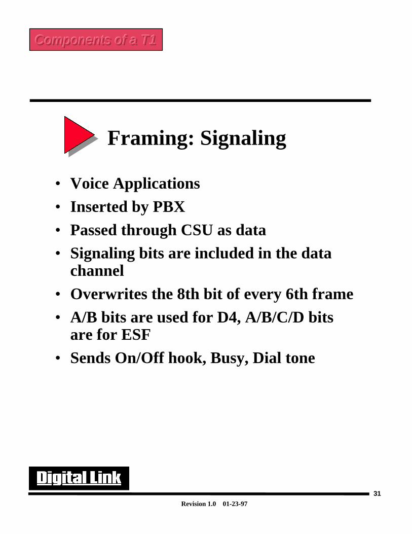
• Voice Applications• Inserted by PBX• Passed through CSU as data• Signaling bits are included in the data
channel• Overwrites the 8th bit of every 6th frame• A/B bits are used for D4, A/B/C/D bits
are for ESF• Sends On/Off hook, Busy, Dial tone
Framing: Signaling
Components of a T1Components of a T1Components of a T1
Revision 1.0 01-23-97
32
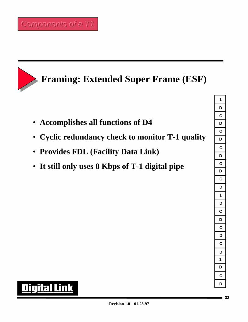
Framing: Extended Super Frame (ESF) Extended Super Frame Format (ESF)- In the early to mid 1980’s, AT&T suggested the implementation of ESF to provide non-disruptiveerror detection and perform non-service-affecting diagnostics on T1 circuits. The increased diagnosticcapabilities of ESF were warranted due to an increase in customer concerns due to performanceconditions on T1 circuits.
Since the purpose of ESF was to increase customer reliability, it was designed such that the enhancedfeatures would not take away from the customers’ throughput. This was accomplished by redefining thesuper frame to contain 24 T1 frames (thus extended super frame). By changing the definition of thesuper frame the same 8K that was used for framing bits in D4 mode could now be used more efficiently.
The ESF frame has 24 framing bits that are used for enhanced functions not covered in the D4 format.Only 6 bits are used for the framing synchronization. The repetitive bit pattern used for synchronizationis 001011. 6 bits are used for a CRC(cyclic redundancy check) that uses an algorithm to verify all 4632bits in the ESF frame. The final 12 bits are used for a facility data link(FDL). This implies that of theoriginal 8k that was used for synchronization in the D4 frame format, is broken down to 2k, 2k, 4k forsynchronization, CRC check and FDL respectively. The FDL is a means through which the telephonecarrier can pro-actively monitor the T1 line without affecting the user data.
Components of a T1Components of a T1Components of a T1
Revision 1.0 01-23-97
33
Framing: Extended Super Frame (ESF)
• Accomplishes all functions of D4
• Cyclic redundancy check to monitor T-1 quality
• Provides FDL (Facility Data Link)
• It still only uses 8 Kbps of T-1 digital pipe
D
1
D
O
C
D
D
1
D
O
C
D
D
C
C
1
D
D
C
D
C
O
D
D
Components of a T1Components of a T1Components of a T1
Revision 1.0 01-23-97
34
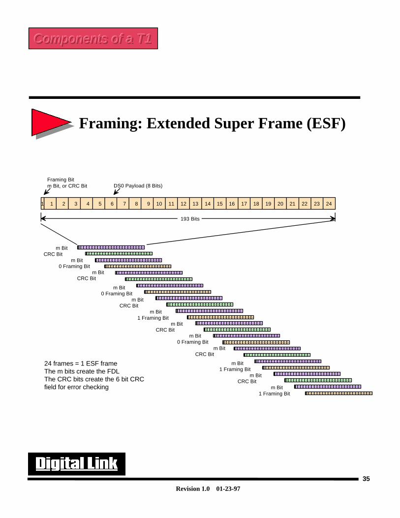
Framing: Extended Super Frame (ESF)
Extended Super Frame Format- The adjoining figure shows all the T1 frames and the associated framing bits as they make up theESF frame. There are 24 T1 frames in an ESF frame. In each T1 frame the framing bits are used toperform their various functions, be it the synchronization, CRC check or FDL.
Components of a T1Components of a T1Components of a T1
Revision 1.0 01-23-97
35
24 frames = 1 ESF frameThe m bits create the FDLThe CRC bits create the 6 bit CRCfield for error checking
1
Framing Bitm Bit, or CRC Bit
193 Bits
1 2 3 4 5 6 7 8 9 10 11 12 13 14 15 16 17 18 19 20 21 22 23 24
DS0 Payload (8 Bits)
1 1 2 3 4 5 6 7 8 9 10 11 12 13 14 15 16 17 1 8 19 20 2 1 22 23 2 4
1 1 2 3 4 5 6 7 8 9 10 11 12 1 3 14 1 5 16 17 1 8 19 20 2 1 22 23 24
1 1 2 3 4 5 6 7 8 9 1 0 11 12 1 3 14 15 16 17 1 8 19 2 0 21 22 2 3 24
1 1 2 3 4 5 6 7 8 9 1 0 11 12 13 14 15 16 17 1 8 19 20 2 1 22 2 3 24
1 1 2 3 4 5 6 7 8 9 10 11 12 13 14 15 16 1 7 18 19 20 21 22 2 3 24
1 1 2 3 4 5 6 7 8 9 10 11 1 2 13 14 1 5 16 17 18 19 2 0 21 2 2 23 24
1 1 2 3 4 5 6 7 8 9 10 11 12 13 14 1 5 16 17 1 8 19 2 0 2 1 22 2 3 24
1 1 2 3 4 5 6 7 8 9 10 11 12 13 14 1 5 16 1 7 1 8 19 20 21 22 23 24
1 1 2 3 4 5 6 7 8 9 10 1 1 12 13 1 4 15 16 1 7 18 19 20 21 22 23 2 4
1 1 2 3 4 5 6 7 8 9 1 0 11 1 2 13 14 15 16 1 7 18 19 2 0 21 2 2 23 24
1 1 2 3 4 5 6 7 8 9 10 11 1 2 13 1 4 1 5 16 1 7 18 19 20 21 2 2 23 24
1 1 2 3 4 5 6 7 8 9 1 0 1 1 12 1 3 1 4 15 16 1 7 18 19 20 21 22 23 24
1 1 2 3 4 5 6 7 8 9 1 0 1 1 1 2 13 14 1 5 16 17 1 8 19 20 21 22 23 24
1 1 2 3 4 5 6 7 8 9 10 11 1 2 13 14 1 5 16 17 18 19 2 0 21 2 2 23 24
1 1 2 3 4 5 6 7 8 9 1 0 11 1 2 13 14 15 16 1 7 18 19 2 0 21 22 2 3 24
1 1 2 3 4 5 6 7 8 9 10 11 12 13 1 4 15 16 1 7 18 19 20 21 22 23 24
1 1 2 3 4 5 6 7 8 9 1 0 11 12 1 3 1 4 15 16 1 7 18 19 20 21 22 23 2 4
1 1 2 3 4 5 6 7 8 9 10 11 1 2 13 1 4 15 16 17 18 1 9 20 21 2 2 23 24
1 1 2 3 4 5 6 7 8 9 10 11 12 13 1 4 15 16 17 18 19 20 21 22 23 24
1 1 2 3 4 5 6 7 8 9 10 1 1 12 13 14 15 16 17 1 8 19 20 21 22 23 2 4
1 1 2 3 4 5 6 7 8 9 10 1 1 12 13 14 15 1 6 17 1 8 1 9 20 2 1 22 23 2 4
1 1 2 3 4 5 6 7 8 9 10 11 12 13 1 4 15 1 6 1 7 18 1 9 20 21 22 23 2 4
1 1 2 3 4 5 6 7 8 9 10 11 12 13 14 1 5 16 17 18 19 20 2 1 2 2 23 2 4
1 1 2 3 4 5 6 7 8 9 10 1 1 12 13 14 1 5 1 6 17 1 8 19 20 2 1 22 23 2 4
m Bit
m Bit
m Bit
m Bit
m Bit
m Bit
m Bit
m Bit
m Bit
m Bit
m Bit
m Bit
CRC Bit
CRC Bit
CRC Bit
CRC Bit
CRC Bit
CRC Bit
0 Framing Bit
0 Framing Bit
1 Framing Bit
0 Framing Bit
1 Framing Bit
1 Framing Bit
Framing: Extended Super Frame (ESF)
Components of a T1Components of a T1Components of a T1
Revision 1.0 01-23-97
36
Framing: ESF Benefits The main benefits of ESF framing are listed to the right. Of the three, one of the most helpful offeatures is the facility data link. The facility data link provides the carrier with a method to be proactiveand possibly correct problems before they occur.
The FDL uses a 14 byte packet (HDLC in nature) that is transmitted using the FDL bits in the ESFframe. The T-carrier uses a device at the carrier office called an LMU (line monitoring unit) which isbridged onto the line and will read the FDL data. If errors are occurring then an alarm will be generatedby the LMU and the problem T1 can be tested or set to out of service (and possibly patched around) untilthe problem can be corrected.
Benefits that are also associated with the ESF FDL include specific carrier registers that are requiredin ESF CSUs. These registers allow the carriers to have access to a history of the problems that haveoccurred on T1s over a 24 hour period. Since the FDL is not in constant use, the CSU that is terminatingthe T1 can also use the FDL link for proprietary functions. For instance, Digital Link and many otherequipment vendors will use the FDL as a method to have a communications link to the remote CSU.This is very advantageous as a local user can now easily see statistics, carrier registers on both the localand far end, as well as verify and change configurations.
Components of a T1Components of a T1Components of a T1
Revision 1.0 01-23-97
37
Framing: ESF Benefits
• Provides continuous, non-interruptive measurement of T-1 system quality
• Allows end to end communications
• Provides CRC-6 error checking capabilities
Components of a T1Components of a T1Components of a T1

Revision 1.0 01-23-97
38
Framing: ESF: FDL (Facility Data Link)
FDL- The use of the FDL is primarily used within the carrier network. The carrier network is composed of aLEC (Local Exchange carrier) and the IEC (Inter Exchange Carrier). The LEC controls the circuit fromthe local carrier office to the the customer premises. The IEC controls the circuits between local carriers.
The main advantage of the facility data link is that it allows the carrier to be proactive in solving T1circuit problems. The FDL has assisted the carrier in maintaining a 98% efficiency, guaranteeing systemup time.
Two specifications were developed to govern communications across the FDL. The first method wascreated by AT&T and was titled technical reference 54016. This method required the CSU to storeperformance information for the past 24 hours in 15 minute increments. The LMU, which is bridgedonto the T1 line, would send a poll requesting information and the attached CSU would respond with theperformance information the LMU requested.
During the break up of AT&T it was decided that the LMU could not communicate past the point ofdemarcation(this is a point that identifies where the telcos responsibility ends and the customers’responsibility begins). Due to the mandate required by the AT&T break up, ANSI (American NationalStandards Institute) developed the requirement that the CSU must transmit it’s performance data towardsthe network once per second. This eliminated the need for the LMU to poll the CSUs as the performanceinformation was always being sent. This document was referred to by ANSI as specification T1.403.
Note: If the T1 is being sent through a DACS then the FDL will be lost. This is due to the DACSreframing the data and therefore destroying all FDL information. On the previous page we discussedbenefits of remote communications to the far end CSU. If a DACS is on the line, this feature of remotecommunication and any other proprietary management capabilities would be lost.
Components of a T1Components of a T1Components of a T1
Revision 1.0 01-23-97
39
• Carrier uses T1.403 protocol forperformance
• AT&T 54016
• Central Office uses LMU for testing
• CSU gathers performance statistics
• Messages are sent out each second
Framing: ESF: FDL (Facility Data Link)
Components of a T1Components of a T1Components of a T1
Revision 1.0 01-23-97
40
Framing: F bits for BERT Testing There are two primary purposes for F-Bits (framing bits) on a T1. Not only do they allow thereceivers to lock onto the repetitive pattern to ensure frame alignment and synchronization, but theycan also be used for In Service Monitoring. This means that the framing bit pattern within a T1frame can be examined for errors, giving the telephone company a good indication of the bit errorrate(BERT) of the T1 line.
Other BERT patterns that are found in external test equipment or intelligent DSU/CSUs, can sendvarious patterns that are used to stress certain characteristics on a T1 line. The QRSS (quasi randomsignal source), 2^20 or 2^23 patterns have bits that repeat in a certain order so that the external testequipment, which is designed to monitor errors in each pattern , can determine if an error has occurredduring transmission. The framing pattern can be thought of in the same way. When errors occur onthe line, there will likely be errors in the framing bits as well as the data bits. In this way, the carriersand customers alike can determine the bit error rate on the line without intrusively taking the circuitdown to do testing.
It is important to note that although bit errors in the framing bits indicate that a problem exists onthe T1 line, to get a true reading of the error rate on the line can’t be accomplished without externaltest equipment.
Components of a T1Components of a T1Components of a T1
Revision 1.0 01-23-97
41
• Synchronization pattern characteristics– Pattern repeats every SF or ESF
– It is unique (not mistaken for Data)
– Frame bits are similar to bit patterns
• Pattern is known in CSU’s and Test sets
• Provides in-service monitoring
• Customer and Carriers become proactive inmonitoring their circuits
Framing: F bits for BERT Testing
Components of a T1Components of a T1Components of a T1
Revision 1.0 01-23-97
42
Line Coding: Pulse DensityPulse Density- When transmitting on a T1, timing and synchronization come from the bits being transmitted.Devices that exist on the T1 line are very sensitive to the bits being transmitted and they use the datapulses to assist in keeping timing and synchronization in tack. To ensure that there are enough datapulses on the line the ‘ones density rule’ was invented.
The ‘ones density rule’ states: In every 24 bits of information to be transmitted, there must be atleast three pulses, and no more that 15 zeros may be transmitted consecutively. A more stringentrequirement set forth by AT&T is : In every 8 bits of information, at least one pulse must be present.
This is very important. If your data must have at least one pulse per byte, then you have to changethe way that data is delivered to the network. A method called ‘pulse stuffing’ was invented to adoptthe one pulse in every 8 bits requirement. This method automatically ensures ones density by takingthe 8th bit in every byte and setting it to a value of 1. The consequences of setting every eighth bit toa 1 in every DS0 implies that the throughput per T1 channel will be reduced to 56Kbps resulting in anet throughput for the T1 to 1.344Mbps. This method is called forced mode of operation on DigitalLink products.
To avoid having to use pulse stuffing other methods to meet ones density were invented. B8ZS isthe line coding that is used to ensure 1’s density without using pulse stuffing. This will be discussed,as well as other methods, in the next few pages.
Components of a T1Components of a T1Components of a T1
Revision 1.0 01-23-97
43
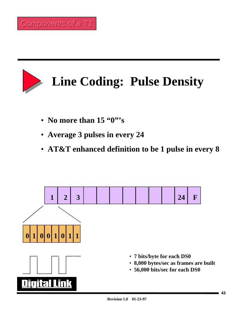
• No more than 15 “0”’s
• Average 3 pulses in every 24
• AT&T enhanced definition to be 1 pulse in every 8
Line Coding: Pulse Density
0 1 0 0 1 0 1 1
• 7 bits/byte for each DS0• 8,000 bytes/sec as frames are built• 56,000 bits/sec for each DS0
F1 2 3 24
Components of a T1Components of a T1Components of a T1
Revision 1.0 01-23-97
44
Line Coding: Alternate Mark Inversion (AMI)
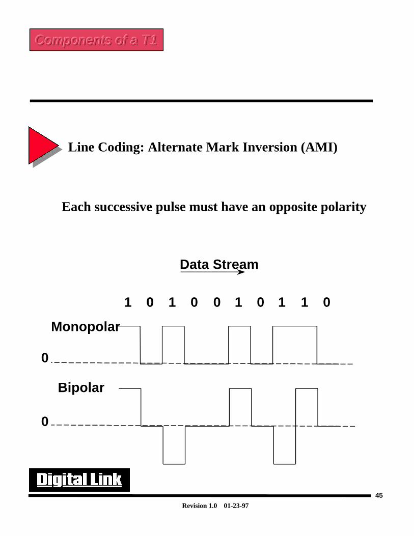
Alternate Mark Inversion (AMI)- There are two main line coding technologies that are used on T1 lines. The first is AMI. AMI is acoding technique that states when two successive logical level 1 states (presence of a pulses) occur thesecond pulse will be of opposite polarity. Any logic levels of 0(absence of pulses) will be transmittedas a zero. If there are zeros in-between the two pulses the second pulse will still have an oppositepolarity. An AMI line encoded signal is the same thing as a Bipolar return to zero signal.
In the diagram that follows a monopolar(or unipolar non-return to zero) signal is shown to contrastto a Bipolar signal. Most customer equipment such as routers, workstations or computers will transmitdata in a unipolar way. This data will then be encoded into the bipolar format for more efficienttransmission to the T1 network(this is one of the functions of the DSU). The principal reason fortranslating a unipolar signal to a bipolar signal is that bipolar signals can be driven farther than unipolarsignals before regeneration is needed. This reduces the number of regenerators that will be needed onthe T1 line. A T1 signal can be driven up to 4000ft before it needs to be regenerated.
Another benefit of an AMI line is that two successive pulses must be of alternate polarity. Forinstance if the first pulse is +3V the next pulse will be -3V. If two successive pulses are +3V (or ofthe same polarity) it is a violation to the bipolar format. This type of error is termed as a BPV(bipolarviolation) and is indicative of format errors on the T1 line. This could be due to a misconfiguration ortoo high of signal levels on a T1 line due to an open circuit. The existence of BPVs on a T1 lineindicates T1 network problems and can be used to assist in diagnosing problems in a network.
Components of a T1Components of a T1Components of a T1
Revision 1.0 01-23-97
45
Each successive pulse must have an opposite polarity
Line Coding: Alternate Mark Inversion (AMI)
Monopolar
Bipolar
Data Stream
1 0 1 0 0 1 0 1 1 0
0
0
Components of a T1Components of a T1Components of a T1
Revision 1.0 01-23-97
46
Line Coding: Bipolar 8 Zero Substitution (B8ZS)
B8ZS (Bipolar 8 Zero Substitution)-
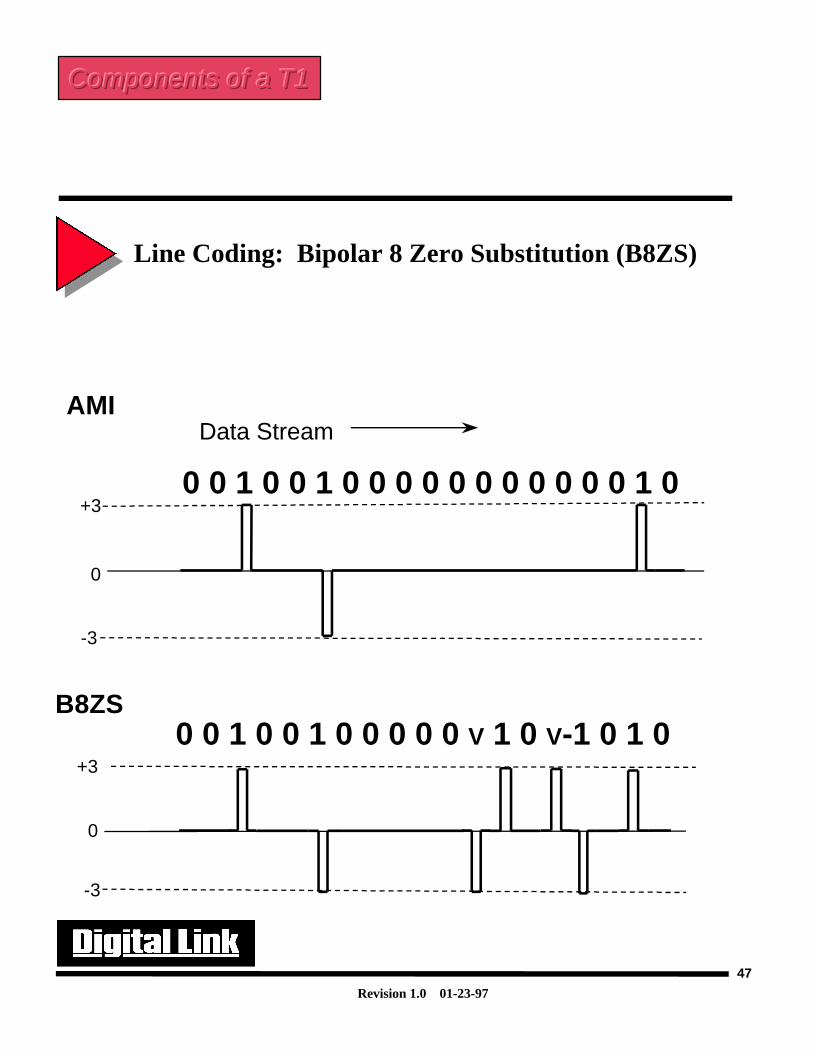
The second type of line coding is B8ZS. B8ZS was created in the Mid 1980’s to allow clear channelcapabilities over a T1 line. AMI line encoding does not provide a method to maintain adequate onesdensity and thus must use pulse stuffing to ensure line integrity. As discussed earlier this means thatthe user will be able to use only 56K of each DS0.
B8ZS line encoding provides a method for the user to get a full 64K DS0 for user data. This is doneby replacing a group of 8 zeros with intentional bipolar violations. This is the only time that BPVs areallowed on the telco facility. The receivers on the T1 line must be configured to look for the B8ZSencoding, else the line will see the substitution for the zeros to be format errors on the line. B8ZS isrecognized on the T1 line by the location of the violations in the fourth and seventh positions in thesubstituted word. By using B8ZS, pulse stuffing is not required and therefore the user will get a full64K DS0.
Some of the problems on T1 can be attributed to a device on the T1 line being configured for AMIand therefore the BPV violations that are intentionally inserted are registered as line errors.
Components of a T1Components of a T1Components of a T1
Revision 1.0 01-23-97
47
Line Coding: Bipolar 8 Zero Substitution (B8ZS)
0 0 1 0 0 1 0 0 0 0 0 0 0 0 0 0 0 1 0
Data Stream
0
+3
-3
AMI
B8ZS0 0 1 0 0 1 0 0 0 0 0 V 1 0 V-1 0 1 0
0
+3
-3
Components of a T1Components of a T1Components of a T1
Revision 1.0 01-23-97
48
Line Coding: Clear ChannelClear Channel- The ability for the user to use all the bits in the data portion of the T1 frame for their own use is calledClear Channel Signaling. Clear channel means that pulse stuffing is not necessary to meet ones density.Most people will associate clear channel capability with B8ZS. This is because B8ZS has the ability tomeet pulse density without using pulse stuffing. There are alternate methods that CSUs can apply thatwill allow clear channel capabilities over an AMI line.
Components of a T1Components of a T1Components of a T1
Revision 1.0 01-23-97
49
Line Coding: Clear Channel
• 12.5% of the digital pipe is wasted tosatisfy bit density requirement
• Ability to use the 12.5% is called“Clear Channel”
Components of a T1Components of a T1Components of a T1
Revision 1.0 01-23-97
50
Data Coding: HDLCHDLC(High Level Data Link Control)-
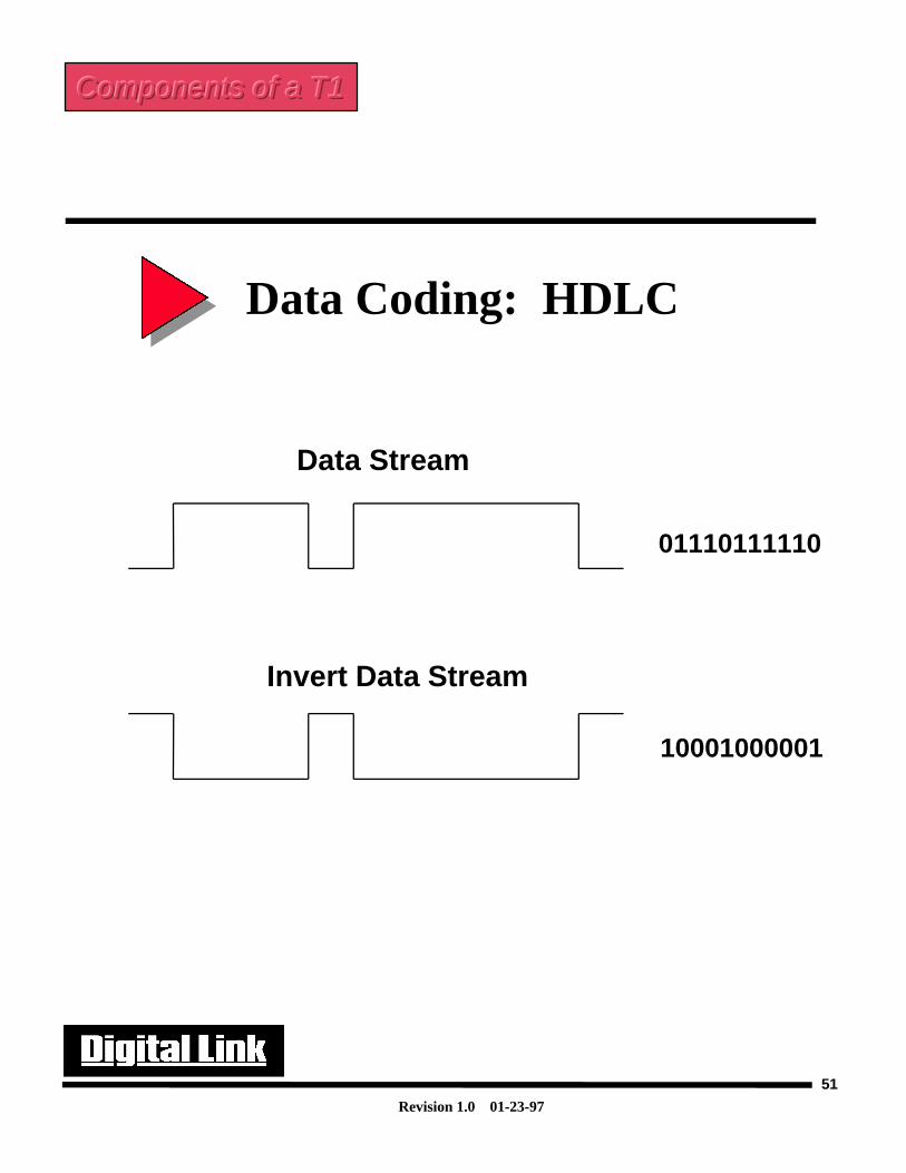
HDLC is an encapsulation protocol that is used in many data communications systems, includingWAN, LAN, and ISDN environments. In the HDLC frame there is a flag which marks the beginningand end of each frame(“01111110”). If the bit sequence were to be repeated inadvertently in anylocation in the HDLC frame it would cause the frame to terminate prematurely. To avoid anunexpected termination of the HDLC frame, the transmitter of the frame will perform a functioncalled zero-bit insertion. In this process the transmitter will scan the sender’s data, looking for the bitsequence 011111. If it finds this sequence, the transmitter will insert a zero immediately after the fifthone. On the receive circuitry the reverse process is done so that original data is not altered.
This implies that in a HDLC frame no more that five ones can be transmitted consecutively. Thismeans that at least one zero must be present in six consecutive bits. With this knowledge we candevelop a means to maintain ones density on a T1 line. This is done on Digital Link products byinverting all the 1s to 0s and 0s to 1s. This occurs before each bit is placed onto a T1 line. Thereverse in done on the remote side of the T1 circuit, so that the original HDLC data is not corrupted.Since we know that in the HDLC frames there are at least one zero in every 6 bits, if this is invertedwe have at least one 1 in every 6 bits, thus maintaining ones density.
The big advantage of this method of coding allows for clear channel capabilities on an AMIfacility.
Components of a T1Components of a T1Components of a T1
Revision 1.0 01-23-97
51
Data Coding: HDLC
01110111110
10001000001
Data Stream
Invert Data Stream
Components of a T1Components of a T1Components of a T1
Revision 1.0 01-23-97
52
FRACTIONAL T-1
Carrier ServicesCarrier ServicesCarrier Services
Fractional T-1(FT1)-
Until 1989, organizations that required data transportation capability in excess of that offered byDDS (Dataphone Digital Service) services were forced to migrate to a T-carrier service or obtainmultiple subrate circuits. In migrating to a T-carrier service the end-user had to pay for twenty-four64kbps channels on a four-wire circuit regardless of the number of channels they actually needed. Ifthey chose to use a subrate circuit solution, the cost to install the individual DDS circuits as well asthe associated cost to install multiple DTE equipment made it an uneconomical solution.
Based on the high cost solutions to get greater than a 64kbps channel, several communicationscarriers started to offer a FT1 service. FT1 is a channelized service where data can be allocated on aper channel basis. Therefore the end-user could now purchase 1 or more DS0’s on a T-1 and reducethe cost of having to pay for a Full T1.
FT1 has many advantages. One of the advantages is that the end-user would only have to pay fullT1 rates from the CPE(customer premises equipment) to the LEC (local exchange carrier) and in-between the LEC (Local exchange carriers) they only had to pay for those time slots that were beingused. In addition to reduced costs, the FT1 service allowed a great measure of expandability.
For Example:
If a company had a need to install to two 64Kbps DS0s/channels for a particular application forconnecting two LANs together and were able to foresee that they would need four DS0s by the endof next year, it would save a lot of time, installation charges, and frustration by having a FT1 service.To install two new lines at 64Kbps in the next year would cost money to install the new 64K lines,additional money in DTE equipment, as well as a lot of time spent in getting the telephone companyout to install. If a FT1 solution were used the customer could place a call to the telco company andmake a few configuration changes and have the higher rate service in a day.
Revision 1.0 01-23-97
53
• Channelized Data• 64 kbps Increments (DS0)• Tariffed by Long Distance Carriers• Uses Full T1 Local Access Circuits
FRACTIONAL T-1
Carrier ServicesCarrier ServicesCarrier Services
Revision 1.0 01-23-97
54
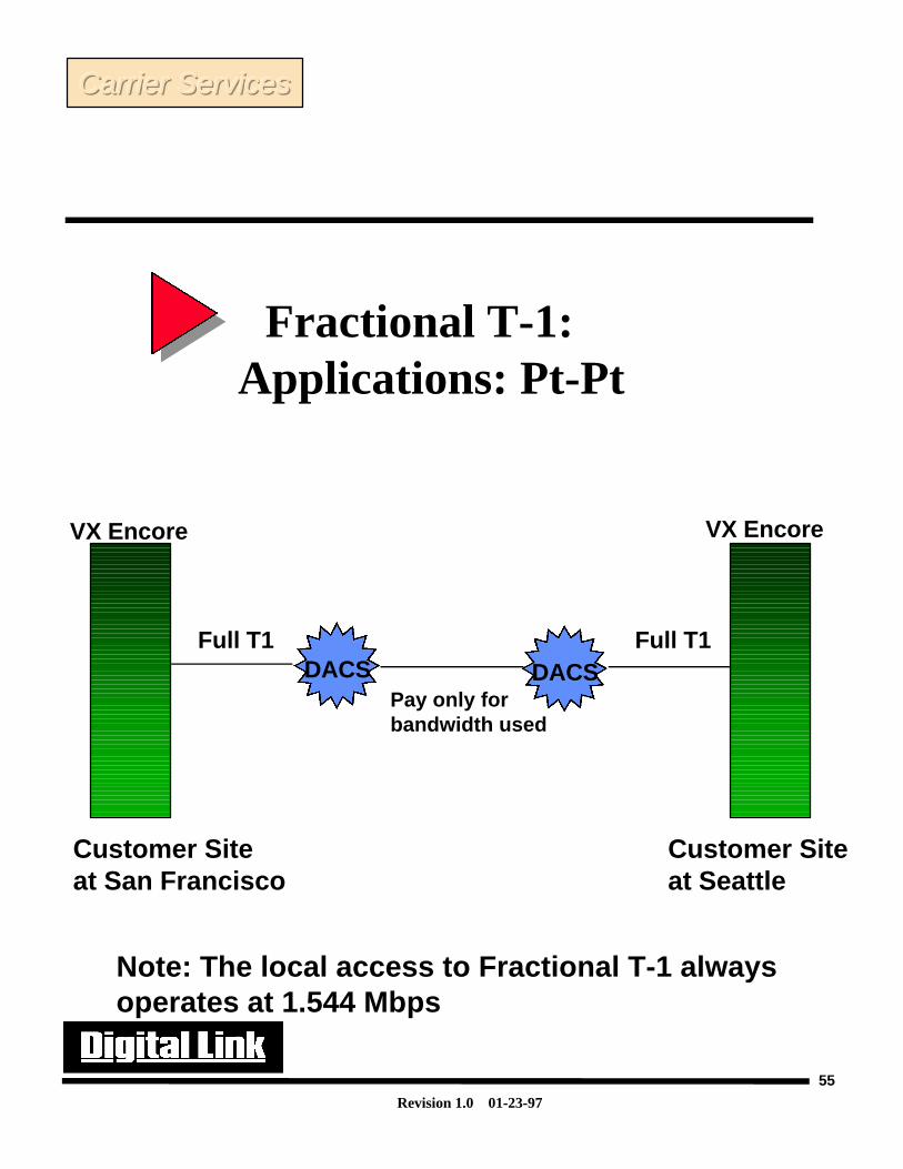
To accomplish FT1 services a device called a DACS (Digital Access Crossconnect System) islocated in the local CO(Central Office) to break down the T1 frame to corresponding 64k channels.These channels or time slots are then reframed with other customers data channels to the far end COwhere they would be placed on the corresponding T1s to each remote location.
In the following example two customers in San Francisco and Seattle would have a Full T1 runbetween each site and their corresponding LEC. At each site there would be a DSU/CSU(VX Encore)that would ensure that the data that was being received and transmitted was sent on the correct timeslots that were paid for and which correlated to the carriers’ configuration (all the rest of the time slotsare stuffed with ones.) Between the LEC in San Francisco and Seattle only the time slots that werepurchased would be sent across the T1 link. The data that was sent from the San Francisco CO wouldbe grouped together with other customers data at that CO(Via a DACS) that was also heading towardthe Seattle CO. All the customers would share the cost of the long distance run and thus save moneyby not having to pay for any unused bandwidth that would have been present in a Full T1. In Seattlea DACS would breakdown the incoming T1 and send the DS0s to each customers full T1 to theirremote sites. The efficiency of sharing the unused part of the T1s over the long distance run cansignificantly save the end-users a lot of money.
Fractional T-1: Applications: Pt-Pt
Carrier ServicesCarrier ServicesCarrier Services
Revision 1.0 01-23-97
55
Fractional T-1: Applications: Pt-Pt
Customer Siteat San Francisco
Customer Siteat Seattle
Full T1 Full T1DACS DACS
Pay only forbandwidth used
Note: The local access to Fractional T-1 alwaysoperates at 1.544 Mbps
VX Encore VX Encore
Carrier ServicesCarrier ServicesCarrier Services
Revision 1.0 01-23-97
56
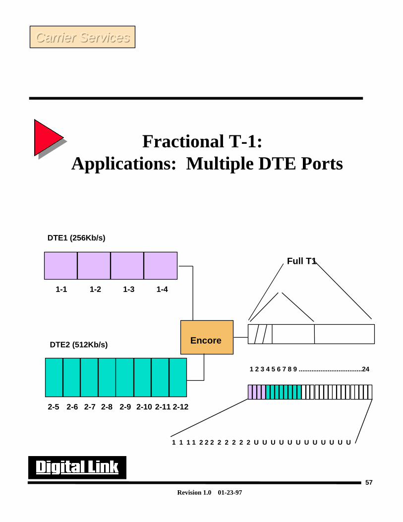
Fractional T-1: Applications: Multiple DTE Ports
In the following application the customer has decided to add an additional port to the DSU/CSU toexpand his service to include eight more time slots for another router or piece of DTE equipment.Data port #1 will supply a clock at the rate of 256kbps(4 time slots) and Data port #2 will supply aclock rate of 512kbps (8 time slots). The DSU/CSU will frame the incoming data so that itcorresponds with the time slots that were agreed upon by the user and the CO. This way the DACS atthe CO will know where to look for data. The unused data channels will be set to 1s.
Carrier ServicesCarrier ServicesCarrier Services
Revision 1.0 01-23-97
57
Fractional T-1: Applications: Multiple DTE Ports
1-1 1-41-31-2
DTE1 (256Kb/s)
DTE2 (512Kb/s)
2-62-5 2-7 2-8 2-9 2-10 2-11 2-12
Encore
1 2 3 4 5 6 7 8 9 ...................................24
Full T1
1 1 1 1 2 2 2 2 2 2 2 2 U U U U U U U U U U U U
Carrier ServicesCarrier ServicesCarrier Services
Revision 1.0 01-23-97
58
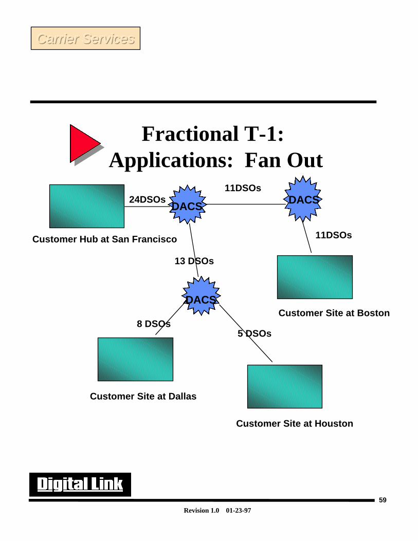
In this application we can see how FT1 can play a critical role in linking multiple sites to a centerhub location in San Francisco. Multiple DACS in the telephone network allows for several remotesites to have a data link to a central hub location. Note that in this example that San Francisco willhave link to all customer sites, but remote sites don’t have the ability to communicate to one another.
It is important at this time to introduce network timing. A lot of problems can be avoided in anetwork by ensuring there is only one timing source on the network. This is called a master-slaveclocking arrangement. In this case the DACS would have to be the master clock. Since a DACShandles breaking down the T1 frames into corresponding DS0s, the DACS will generally have avery accurate clock on the line. The DACS clock ensures that all the data is sent and received in thecorrect time positions so that the receiving device can accurately locate all bits in the T1 frame. Thereceiving device can also receive clocking from the incoming data pulses and thus preserve theoverall network clock that will be passed to the next device. If there were multiple clocks on thenetwork, one device may be looking for data pulses in incorrect locations in time(since the otherdevice would be isolating data based on its own clock which may be different from the clock thatgenerated the data) and thus cause distortion to the data.
Fractional T-1: Applications: Fan Out
Carrier ServicesCarrier ServicesCarrier Services
Revision 1.0 01-23-97
59
Fractional T-1: Applications: Fan Out
Customer Hub at San Francisco
Customer Site at Dallas
Customer Site at Houston
Customer Site at BostonDACS
DACSDACS
24DSOs
13 DSOs
11DSOs
11DSOs
8 DSOs5 DSOs
Carrier ServicesCarrier ServicesCarrier Services
Revision 1.0 01-23-97
60
Frame Relay
Frame Relay-
Frame relay is commonly referred to as a “packet based” technology. A packet is a bundleof data that is organized in a specific way for transmission. The data is placed in a particularmanner such that vital information can be obtained and is called a frame. The frame controlsvital information such as addressing, error checking, and start and stop sequences.
Each frame that is generated by the DTE equipment will be placed upon the physicalmedium, be it FT1, T1 or T3, and sent out to the local carrier office. The local carrier will thenhave equipment that will strip off the T1 data (the individual frames) and route them through thetelco facilities to the far end destination. Frame Relay is referred to as a connection-orientedprotocol. This is because before a connection can be established between two devices a callsetup procedure must be followed. This procedure establishes a permanent virtual connectionbetween the remote units and the local unit.
The two main benefits associated with frame relay are reduced costs and the capability ofmaintaining multiple connections to several remote locations using a single physical connectionto the carrier(FT1, T1 or T3). Reduced costs are achieved by the same principles behind FT1 inthat you only have to pay for each packet that is sent. The benefit of being able to establishmultiple remote connections via a single local connection point saves not only money, but savesresources as well. If we tried to gain the same benefits of frame relay by using T1 technologyonly, it would require several T1s to be run from the local site to each remote location and as thenetwork grew, the number of T1’s required to maintain full communication between all siteswould become unfeasible.
One of the limitations of frame relay is latency. Latency is the delay that occurs by routingeach packet through the telephone network. Packets that are sent may take different routes inthe telco “cloud” and it is possible that a packet that was sent later from the local DTE devicecould be received first at the remote end. Therefore the packet will have to be buffered in theend DTE equipment until the full packet can be processed. The latency inherent in Frame Relaymakes it unacceptable for voice or video applications that need to be transmitted and received ina “real-time” environment.
The key point in this discussion is that frame relay can be transmitted across a T1 and is usedfor data only. It allows for inter-connectivity between multiple sites using only a singleconnection to the carriers.
Frame relay goes beyond the scope of this course. A separate course is available for framerelay and ATM technologies.
Carrier ServicesCarrier ServicesCarrier Services
Revision 1.0 01-23-97
61
Frame Relay
• Uses FT1, T1, T3
• Packet Technology
• Connection oriented
• Latency problems result in data traffic only
• Provides Cost effective inter-connectivity for multiple locations
Carrier ServicesCarrier ServicesCarrier Services

Revision 1.0 01-23-97
62
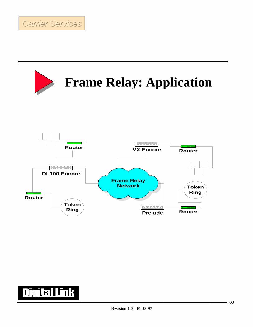
Frame Relay: ApplicationFrame Relay Application-
Frame relay as discussed previously is good for multiple site connectivity. Thispicture shows how frame relay can be used to connect to three different locations.The key difference between frame relay and FT1 is that frame relay allows all sites tocommunicate to one another without having to have a permanent T1 connection toeach site. Only a single connection is required from the user site to the local carrierat the central office and the carrier will route the information to the correct remotesite.
Carrier ServicesCarrier ServicesCarrier Services
Revision 1.0 01-23-97
63
Frame RelayNetwork
DL100 Encore
Router
TokenRing
Router
VX Encore Router
Prelude
TokenRing
Router
Frame Relay: Application
Carrier ServicesCarrier ServicesCarrier Services
Revision 1.0 01-23-97
64
Switched Multi-Megabit Data Services (SMDS) - SMDS is a cell based technology. Cell based technology simply means that thedata that is sent out on the network is of fixed length. To convert the incoming datafrom the DTE equipment to a fixed length cell, a DSU is required to segment the dataand place it into a T1/T3 frame format. The incoming cells from the network will thenbe re-assembled prior to being sent to the DTE. This process is commonly referred toas SAR (Segmentation and Re-assembly).
The main advantage to using a cell based technology is that is easier for thenetwork equipment to process fixed length cells than variable length packets. Itallows for more efficient operation and thus a cost reduction to the end user. Thetelephone company will charge the SMDS user based on the class of service that isdesired.
Data from the DTE device is segmented down into cells and then placed into aT1/T3 frame. SMDS can handle data and packetized voice and video applications.
SMDS is said to be a connectionless service as call setup is not required.
SMDS goes beyond the realm of this course. If you desire more information andtraining on SMDS a separate course is available from Digital Link.
SMDS
Carrier ServicesCarrier ServicesCarrier Services
Revision 1.0 01-23-97
65
SMDS
• T1 and T3• Switched Multi- Megabit Data Services• Connectionless Service• Cell Based Technology• Needs special DSU/CSU to Xmit to network
Carrier ServicesCarrier ServicesCarrier Services
Revision 1.0 01-23-97
66
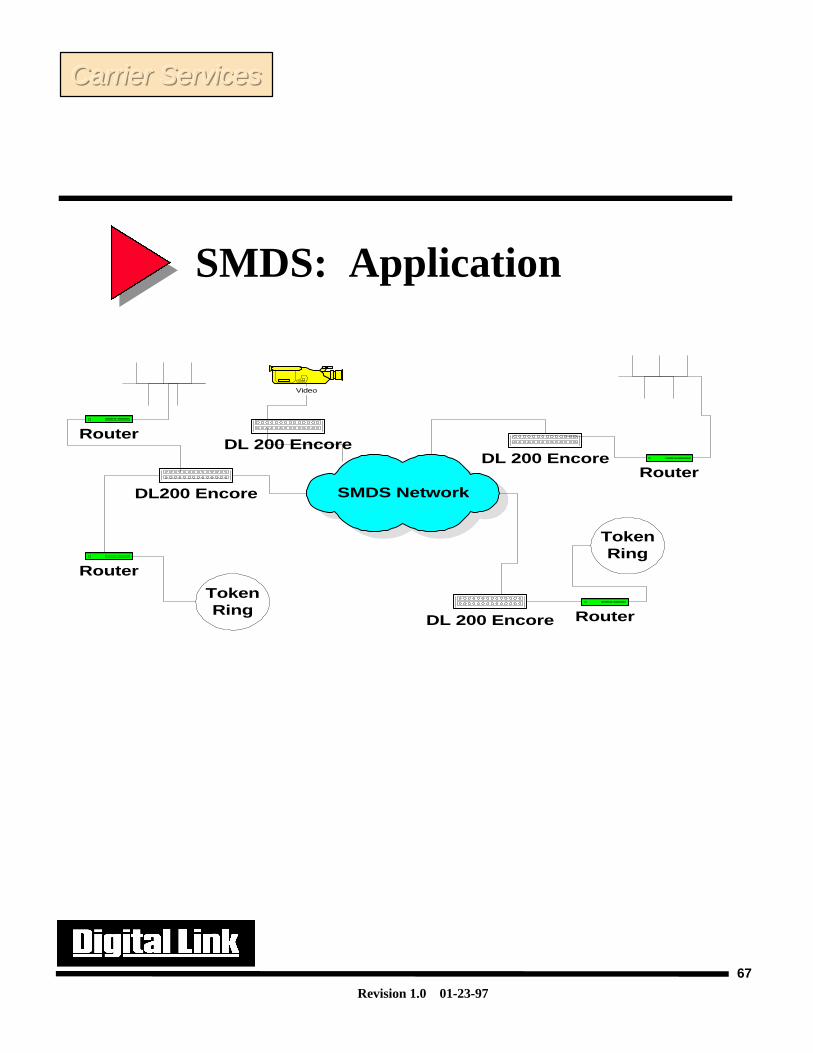
SMDS- In this picture we see that a special DSU/CSU is required to accomplishSMDS technology. This DSU/CSU will segment the data from the DTE deviceand send out cells to the telco network to be processed. It allows for multiplesites to be linked together without the need of individual T1s being run to eachsite.
SMDS: Application
Carrier ServicesCarrier ServicesCarrier Services
Revision 1.0 01-23-97
67
SMDS NetworkDL200 Encore
Router
TokenRing
Router
DL 200 EncoreRouter
DL 200 Encore
TokenRing
Router
DL 200 Encore
Video
SMDS: Application
Carrier ServicesCarrier ServicesCarrier Services
Revision 1.0 01-23-97
68
ATM- ATM like SMDS is a cell based technology. As such it is more efficient thanpacket switched technologies such as Frame Relay and ISDN (Integrated ServicesDigital Network). Since ATM is a connection oriented service is better able to providevoice, data and video. ATM is mostly used in T3 applications, but can now be found on T1 services.
ATM goes beyond the realm of this course. If you desire more information andtraining on ATM a separate course is available from Digital Link.
Asynchronous Transfer Mode (ATM)
Carrier ServicesCarrier ServicesCarrier Services
Revision 1.0 01-23-97
69
Asynchronous Transfer Mode (ATM)
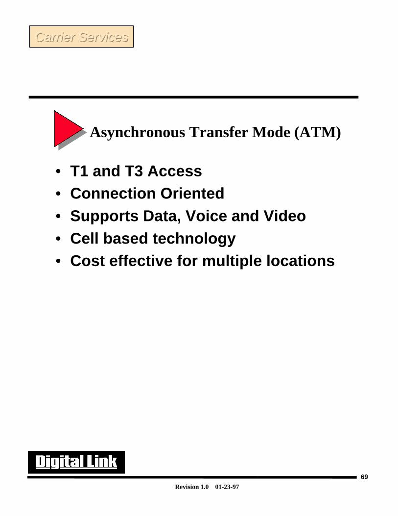
• T1 and T3 Access• Connection Oriented• Supports Data, Voice and Video• Cell based technology• Cost effective for multiple locations
Carrier ServicesCarrier ServicesCarrier Services
Revision 1.0 01-23-97
70
T1 Alarms And Errors Troubleshooting T1 networks can be a trying exercise. In many user applications the T1 link iscritical to network operation. This means that if the link goes down, many people will be beating onyour door to get answers and to isolate any problem.
In order to understand how to isolate problems on a T1 line you have to understand the basicdiagnostic capabilities and alarms that are available for your use. There are several characteristics thatare required on a T1 that can be used to assist you in your isolation process.
The first step in isolating any problem is to become familiar with your configuration options. Youwill need to be able to find what type of T1 line framing and coding are being used. The ESF frameformat has enhanced capabilities which allow the user to gain a greater understanding on what isoccurring in the network. We will discuss in the next few pages on how best to isolate networkproblems as they occur.
TroubleshootingTroubleshootingTroubleshooting
Revision 1.0 01-23-97
71
T1 Alarms And Errors
ARGHHHH!!!!!!!!!! Mynetwork isdown! How do Idiagnose myproblem??????
TroubleshootingTroubleshootingTroubleshooting
Revision 1.0 01-23-97
72
Troubleshooting T1 Tips In this section we will discuss various tell tale signs that your T1 network is experiencing difficulties.Initially we will discuss the three main T1 alarm states that can assist in pin pointing network problems.We will then investigate ESF alarm declarations and the different types of errors that can be found onT1s and why ESF performs better for trouble isolation techniques.
Wiring problems are common on T1s. Using the proper type of cable and wiring it correctly isessential. We will show the pin out and connectors that are currently used for T1s.
External test equipment is often the best way to isolate network problems. We will discuss thedifferent types of network test equipment that are available and how best to use these devices to isolatenetwork problems.
TroubleshootingTroubleshootingTroubleshooting
Revision 1.0 01-23-97
73
Troubleshooting T1 Tips• Look at T1 Alarm States• Know definitions of carrier ESF
declarations (per TR62411)• Understand wiring concepts• Know and use test equipment• Be aware of common network
problems• Isolate problems using loopbacks
TroubleshootingTroubleshootingTroubleshooting
Revision 1.0 01-23-97
74
T1 Alarm States
•Red CFA (Carrier failure alarm)- This alarm is generated by the receipt of 2 - 3 seconds ofcontinuous LOS or OOF. An OOF is declared when any 2/4 consecutive frame synchronization bits areincorrect. The alarm is cleared in about 10-20 seconds of receiving a good network signal. Upondeclaration of a red alarm a yellow alarm is generated.
•Yellow CFA- A yellow alarm is received if the far end unit is in a red alarm condition. In D4framing, a yellow alarm is declared when 0s are present in the second position in every byte (channel) inthe DS1 frame. In ESF, a repetitive 16 bit pattern consisting of 8 ones followed by 8 zeros in the FDLfor a minimum of one second is indicative of a yellow alarm state.
TroubleshootingTroubleshootingTroubleshooting

Revision 1.0 01-23-97
75
T1 Alarm States
• Red Alarm
• Yellow Alarm
Digital Link
EFS 100 PERCENT
T1 DIGITAL SERVICE MULTIPLEXER Encore Digital Link
EFS 100 PERCENT
T1 DIGITAL SERVICE MULTIPLEXER Encore
IN RED ALARMIN YELLOW ALARM
YELLOW ALARM PATTERN
TroubleshootingTroubleshootingTroubleshooting
Revision 1.0 01-23-97
76
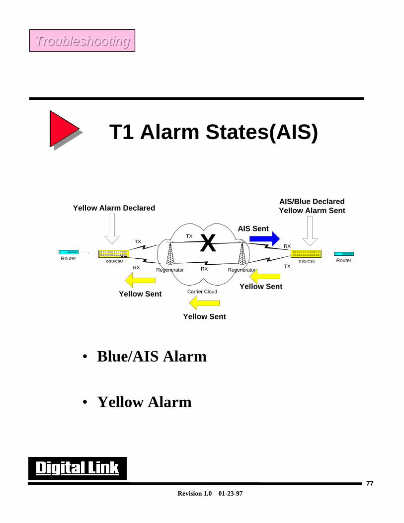
• AIS (Alarm Indication Signal)- Upon loss of DTE equipment AT&T specification TR62411suggests that an Unframed all 1s be sent on a DTE loss of signal. As this is an alarm that is created for aCSU, if DSU portion loses signal a framed all 1s is sent. AIS is also known as a blue or keep alivesignal. This alarm will indicate that a device on the T1 or connected to the CSU has failed. If an AISalarm is received a yellow alarm will be generated.
In the adjoining picture it is shown that for a DSU/CSU to declare an AIS or Blue alarm that a LOS musthave occurred in the carrier network, before the last regenerator in the network. The Blue alarm willcause the DSU/CSU to send a yellow alarm pattern. Regenerators are similar in functionality to a stand-alone CSUs.
T1 Alarm States (AIS)
TroubleshootingTroubleshootingTroubleshooting
Revision 1.0 01-23-97
77
T1 Alarm States(AIS)
TroubleshootingTroubleshootingTroubleshooting
Regenerator Regenerator
Carrier Cloud
RouterDSU/CSU RouterDSU/CSU
TX
RX TX
RXXTX
RX
AIS Sent
AIS/Blue DeclaredYellow Alarm Sent
Yellow Sent
Yellow Sent
Yellow Sent
Yellow Alarm Declared
• Blue/AIS Alarm
• Yellow Alarm
Revision 1.0 01-23-97
78
Types of Errors on a T1
All errors on a T1 can be broken down into two major categories, format and logic errors.
Format errors on a T1 are errors that violate the signaling format set forth by AT&T and ANSI (inspecs 62411 and T1.403 respectively). These are conditions that we discussed earlier. They may be errorsin the coding method, such as BPVs, or violations in the number of pulses received. Both D4 and ESFwill be able to detect format errors.
Logic errors on a T1 are errors that are introduced by the insertion or removal of pulses in the datastream. These errors will be shown in greater detail in the next figure. Logic errors in the data streammay not necessarily cause format errors on the line. Unless logic errors occur within the framing bits ofthe T1, the D4 frame format will not be able to detect them. One of the advanced characteristics in theESF frame format allows for additional trouble isolation through its CRC check, which will be enableDSU/CSUs to detect additions or removal of pulses within the T1 data stream. There are also additionalESF alarm states that are stored in 24 hours statistics that are available through the FDL. The additionalalarm states will be described shortly.
TroubleshootingTroubleshootingTroubleshooting
Revision 1.0 01-23-97
79
Types of Errors on a T1
Format Errors-
Errors that violate DS1 signaling specification
• BPV, Loss of Signal, Loss of Frame, ExcessiveZeros, Ones density violations, Incorrect pulsewidths, Incorrect signal levels.
Logic Errors
Errors that occur when a pulse is added or removedfrom the data stream, hence, the data is altered.
• Won’t always produce format errors.
• Multiple Logic errors may keep AMI coding intact.
• D4 framing format will not detect logic errors unlessthey are in the framing bits
TroubleshootingTroubleshootingTroubleshooting
Revision 1.0 01-23-97
80
Logic Errors Vs. Format Errors
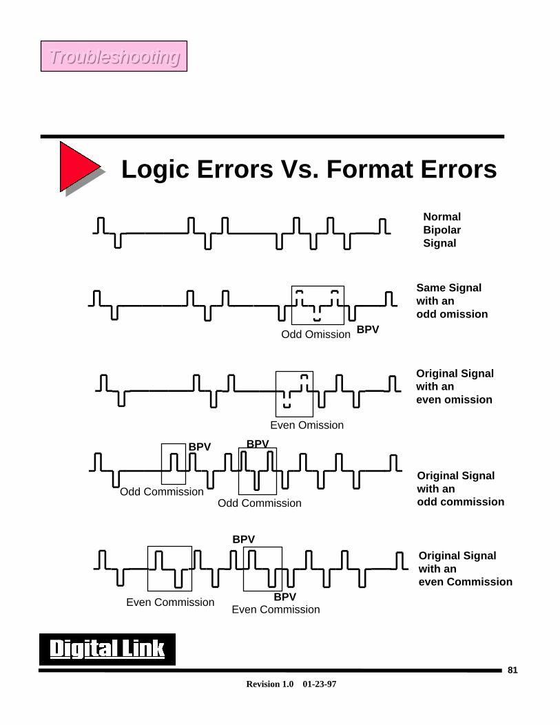
This picture shows that if pulses are inserted or removed, sometimes a format error will not occur. InD4 format, errors will not be seen unless the pulse removal or insertion occurs in the framing bits in theT1 frame. In the ESF format, both types of errors(format and logic) can be detected by the CRC check.The CRC 6 capabilities of the ESF frame will compute a value representing of all bits within the framebefore it gets sent out to the T1 network. The receiving device will reverse the computation to ensurethere aren’t any errors within the bit stream. In this, we can see that ESF format will have a bettercapability to detect errors on the T1.
The enhanced capabilities of the ESF frame allows the carrier to determine accurately the trueperformance of the line. With the CRC check we see that the ESF frame can determine errors in the datastream as well as in the frame bits. In the ESF frame format the FDL also gives us the capability to viewthe statistics on the line in 15 min intervals for 24 hours. The next page shows the statistics that can beobtained in an ESF CSU that will allow greater trouble isolation on a T1.
As discussed earlier, in AT&T’s 54016 specification, statistics are held within the CSU and are heldin three registers. These are the termed the Carrier registers. The carrier registers hold data in threelocations. The registers are titled the Current 15 minute interval, the 24 interval and the detailed 24 hourinterval (that holds the data for each 15min interval over 24 hours). In ANSI T1.403 the statistics aresent towards the T1 every second. In TR54016 these values have to be polled.
TroubleshootingTroubleshootingTroubleshooting
Revision 1.0 01-23-97
81
Logic Errors Vs. Format Errors
NormalBipolar Signal
Same Signalwith an odd omission
BPVOdd Omission
Even Omission
Original Signalwith an even omission
Original Signalwith an odd commission
BPVBPV
Odd CommissionOdd Commission
Original Signalwith an even Commission
Even CommissionEven Commission
BPV
BPV
TroubleshootingTroubleshootingTroubleshooting
Revision 1.0 01-23-97
82
ESF Alarm Declarations On the next page are the errors that can be detected and stored in the ESF statistics registers. Note thatmost of these ESF alarm conditions rely on the added feature in an ESF frame that allows for CRCchecking. Common alarms like LOS and LOF will also be detected in a D4 CSU, but they do not have tobe logged in a register (although some vendors do put a D4 statistics log for user convenience).
Format errors will be detected by both a ESF CSU and D4 CSU.
Logic errors will be detected only by and ESF CSU.
TroubleshootingTroubleshootingTroubleshooting
Revision 1.0 01-23-97
83
ESF Alarm Declarations
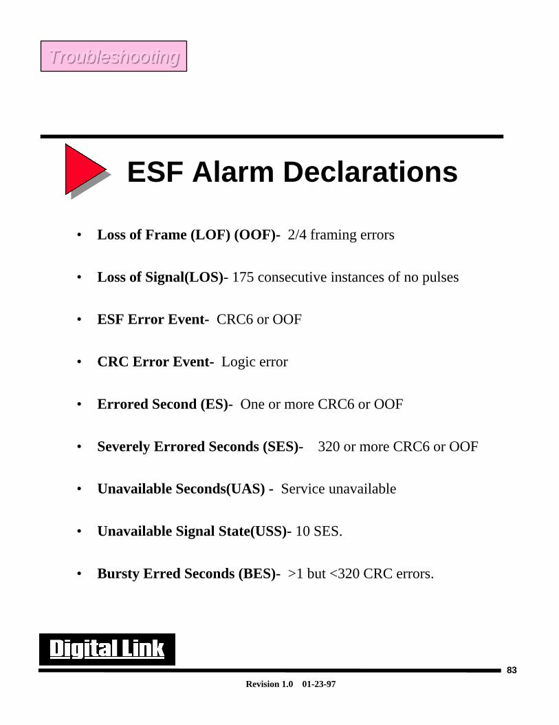
• Loss of Frame (LOF) (OOF)- 2/4 framing errors
• Loss of Signal(LOS)- 175 consecutive instances of no pulses
• ESF Error Event- CRC6 or OOF
• CRC Error Event- Logic error
• Errored Second (ES)- One or more CRC6 or OOF
• Severely Errored Seconds (SES)- 320 or more CRC6 or OOF
• Unavailable Seconds(UAS) - Service unavailable
• Unavailable Signal State(USS)- 10 SES.
• Bursty Erred Seconds (BES)- >1 but <320 CRC errors.
TroubleshootingTroubleshootingTroubleshooting
Revision 1.0 01-23-97
84
Upon initial installation of a T1 circuit, most problems are caused by incorrect wiringof the four T1 leads.
The first consideration in wiring a T1 is to ensure that a high quality cable is beingused. Typical brand names for a T1 cable is ABAM or T-Screen. These types ofcables are individually twisted and shielded cables. The transmit and receive pairmust be on their own twist. That is Tx Tip and Ring must be twisted together. A T1cable is a 4 wire full duplex cable. This means that there are two wires for transmit andtwo wires for receive so that communications can occur in both directions(towards thenetwork and towards the DTE device) on the line at the same time. The two wires forTX and RX are named Tip and Ring. Tip is a positive representation of the signal andRing is the negative.
If the wires in the TX and RX pair were twisted incorrectly, a phenomenon calledcross talk will result on the T1 and errors such as BPV, CRCs, and LOS may occur.Typical wire gauge is 22-26 gauge.
Wiring On T1 Port
TroubleshootingTroubleshootingTroubleshooting
Revision 1.0 01-23-97
85
Wiring On T1 Port
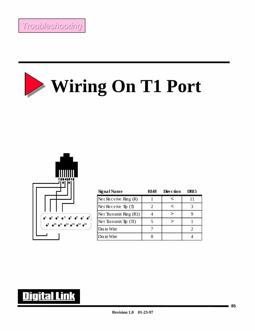
1 2 3 4 5 6 7 8
9 10 11 12 13 14 15
Signal Name RJ48 Direc tion DB15
Net Rece ive Ring (R) 1 < 11
Ne t Rece ive Tip (T) 2 < 3
Ne t Transmit Ring (R1) 4 > 9
Ne t Transmit Tip (T1) 5 > 1
Dra in Wire 7 2
Dra in Wire 8 4
TroubleshootingTroubleshootingTroubleshooting
Revision 1.0 01-23-97
86
Test Equipment
There are many vendors that make equipment to troubleshoot data communication lines. TTC is themost renown and has become a leader in the manufacturing of test equipment. IDS also creates testequipment that is less expensive, but is equally good for testing data networks.
There are two areas for WAN connectivity that need to be tested. One is the network connection andthe other is the DTE uni-polar synchronous connection.
•T-Berd 209/211- This is used to test the network by providing T1 frame formatted patterns to isolate any network problems. It can also be used with fractional T-1’s or in a unframed format
•Fireberd 6000- Is generally used to test the DTE interface and supports synchronous protocols like V.35/RS449. It sends a synchronous data pattern to test the DTE equipment and connected devices. The F.B.6000 offers the ability to change modules and thus has the ability to also perform as a direct T1 test set as well like the T-Berd 209.
TroubleshootingTroubleshootingTroubleshooting
Revision 1.0 01-23-97
87
Test Equipment
• Network test equipment-– T-Berd
• Data communications test equipment-– Fireberd
TroubleshootingTroubleshootingTroubleshooting
Revision 1.0 01-23-97
88
Test Equipment: Patterns
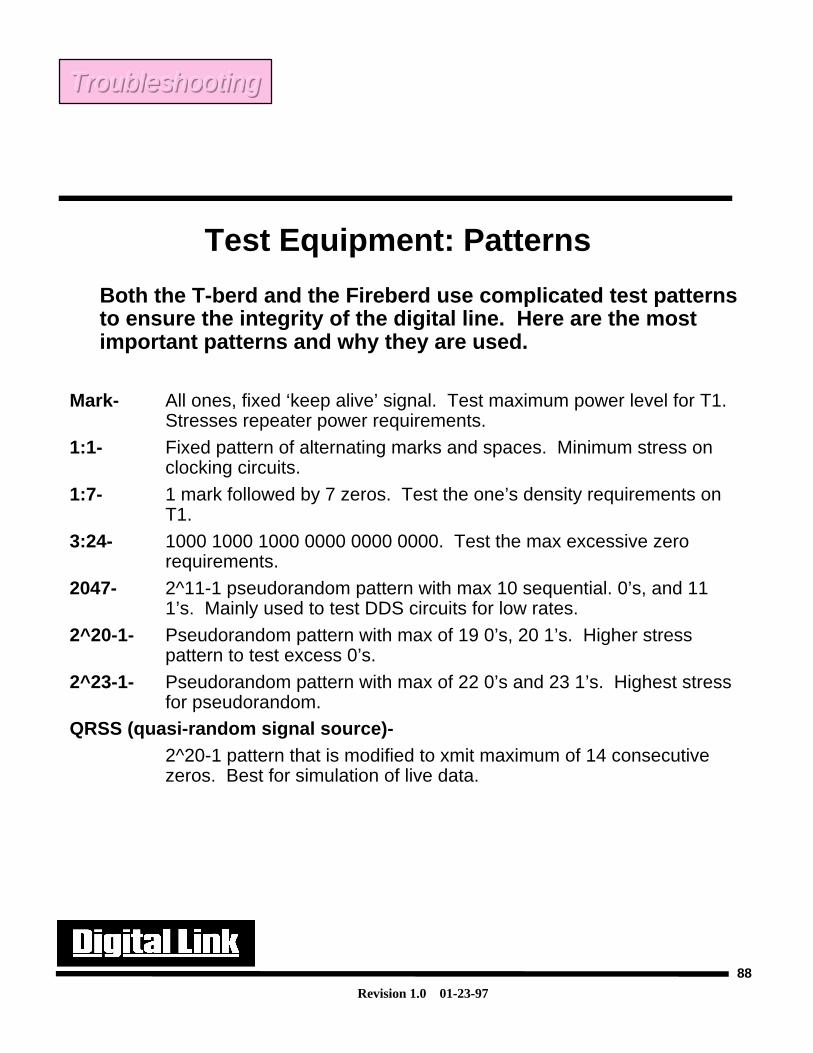
Both the T-berd and the Fireberd use complicated test patternsto ensure the integrity of the digital line. Here are the mostimportant patterns and why they are used.
Mark- All ones, fixed ‘keep alive’ signal. Test maximum power level for T1.Stresses repeater power requirements.
1:1- Fixed pattern of alternating marks and spaces. Minimum stress onclocking circuits.
1:7- 1 mark followed by 7 zeros. Test the one’s density requirements onT1.
3:24- 1000 1000 1000 0000 0000 0000. Test the max excessive zerorequirements.
2047- 2^11-1 pseudorandom pattern with max 10 sequential. 0’s, and 111’s. Mainly used to test DDS circuits for low rates.
2^20-1- Pseudorandom pattern with max of 19 0’s, 20 1’s. Higher stresspattern to test excess 0’s.
2^23-1- Pseudorandom pattern with max of 22 0’s and 23 1’s. Highest stressfor pseudorandom.
QRSS (quasi-random signal source)-2^20-1 pattern that is modified to xmit maximum of 14 consecutivezeros. Best for simulation of live data.
TroubleshootingTroubleshootingTroubleshooting
Revision 1.0 01-23-97
89
Test Equipment: Patterns
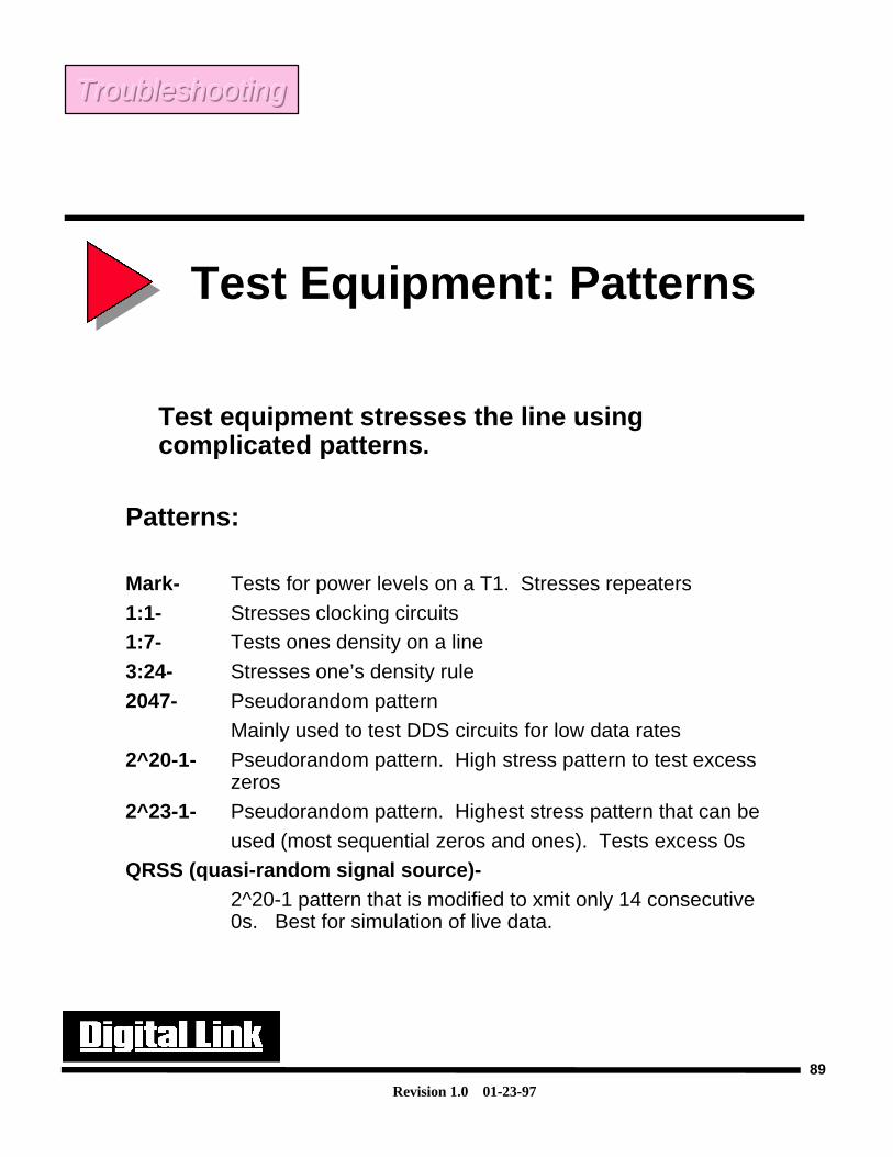
Test equipment stresses the line usingcomplicated patterns.
Patterns:
Mark- Tests for power levels on a T1. Stresses repeaters
1:1- Stresses clocking circuits1:7- Tests ones density on a line
3:24- Stresses one’s density rule
2047- Pseudorandom pattern
Mainly used to test DDS circuits for low data rates
2^20-1- Pseudorandom pattern. High stress pattern to test excesszeros
2^23-1- Pseudorandom pattern. Highest stress pattern that can be
used (most sequential zeros and ones). Tests excess 0sQRSS (quasi-random signal source)-
2^20-1 pattern that is modified to xmit only 14 consecutive0s. Best for simulation of live data.
TroubleshootingTroubleshootingTroubleshooting
Revision 1.0 01-23-97
90
Common Network Problems
BPV- BPVs are one of the most common errors that appear on a copper T1 facility. They can becaused by bad signal levels on the wire or opens in the circuit. They also may be caused by a deviceon the line has an improper coding style (i.e. B8ZS). Problems may be isolated using the testequipment discussed before in conjunction with loopbacks.
Frame and CRC errors- These errors stored and used for performance monitoring. They canindicate that a line is degrading or a component on the network is failing. CRC errors can be detectedin the ESF framing format only.
Wiring- All wires should be good quality T1 cable. Specs call for the cable to be 100 ohms, 24gauge, individually twisted and shielded cable pairs. Levels on the T1 line must not be less than -24- -26 DB.
Jitter and Wander- Jitter is defined as a phase displacement in time of a signal from its originalposition. Due to the many components used on a T1 line(multiplexers, DACS, regenerators) there isalways going to be processing time to pass the signal through the circuitry. This time delay is termedas jitter. A certain amount of jitter is allowed on a T1. Low levels of jitter (below 10HZ) is calledwander. Jitter may cause timing slips or CRC errors.
Timing Slips- Timing slips are most often caused by having multiple clocks on a single line or byhigh levels of jitter. Uncontrolled slips may be caused when clocking or jitter problems are so severethat the buffers in the attached equipment must be cleared and the framing is lost. Controlled slipsoccur when the T1 equipment clears its buffers, but maintains framing.
TroubleshootingTroubleshootingTroubleshooting
Revision 1.0 01-23-97
91
Common Network Problems
• Bipolar Violations (BPV’s): Only on copper
• Framing Errors
• CRC-6 Errors (ESF only)
• Wiring and signal levels
• Jitter and Wander
• Timing slips
TroubleshootingTroubleshootingTroubleshooting
Revision 1.0 01-23-97
92
In trouble shooting T1 networks there are three main loopback tests that can be performed.
Net Loopback- This is a required loopback from AT&T spec. 62411. The network loopback isactuated by the telephone company or from CSUs through the front panel or terminal interfaces. Itsmain purpose is to allow the network to troubleshoot network problems. It is actuated by a 10000repetitive unframed pattern and can be taken down by a 100 unframed pattern. It loops the networksignal back towards the network, thus allowing the carrier to test the integrity of the T1 line. Theframing is not regenerated. This test will test the LBO on the DSU/CSU and the network.
Payload Loopback- This is a required loopback from AT&T spec 62411. It loops that data from thenetwork back towards the network. This test tests not only the T1, but the DSU/CSU as well. The datais reframed and regenerated before being sent back towards the network.
DTE Loopback- This loopback is used to test the attached DTE equipment and the DSU/CSU. Itloops the data from the DTE back towards the DTE. It runs through the internal circuitry of theDSU/CSU and through a simulated 4000ft line before being sent back towards the DTE.
Note: Depending on the specification that is used the loop up and loop down codes may be different forthe network and the payload loopbacks. T1.403 sends loop up and loop down codes across the FDL,where TR54016 sends the loop up and down codes in-band.
Troubleshooting: Loopbacks
TroubleshootingTroubleshootingTroubleshooting
Revision 1.0 01-23-97
93
Troubleshooting: Loopbacks
• Helps to isolate network and DTE problems
• Required by carriers for DSUs and CSU’s
• Three Types• Network, Payload and DTE
TroubleshootingTroubleshootingTroubleshooting
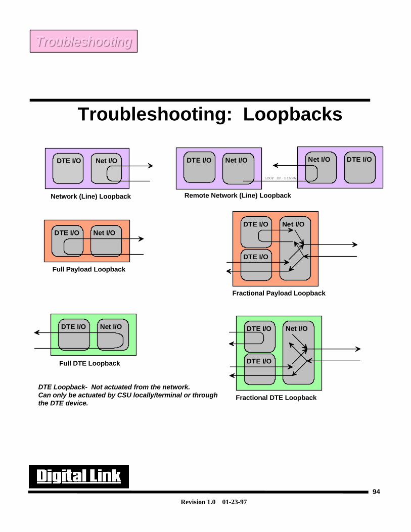
Revision 1.0 01-23-97
94
Full Payload Loopback
DTE I/O Net I/ODTE I/O Net I/O
DTE I/O
Fractional Payload Loopback
DTE Loopback- Not actuated from the network.Can only be actuated by CSU locally/terminal or throughthe DTE device.
Full DTE Loopback
DTE I/O Net I/O DTE I/O Net I/O
DTE I/O
Fractional DTE Loopback
Network (Line) Loopback
DTE I/O Net I/O
Remote Network (Line) Loopback
DTE I/O Net I/O Net I/O DTE I/O
LOOP UP SIGNAL
Troubleshooting: Loopbacks
TroubleshootingTroubleshootingTroubleshooting

Revision 1.0 01-23-97
95
This page is intentionally left blank
Revision 1.0 01-23-97
96
Summary
In conclusion, the principles that have been discussed and shall be
understood are:
• Analog to digital conversion.
• The basics on how the T1 frame is constructed
– 193 bits. 192 bits for data, 1 bit for overhead
– 24 8 bit channels
• The different framing methods and their benefits.– ESF has CRC, FDL as wells as performance registers. ESF can
detect both logic and format errors on a line.
– D4 only uses overhead for synchronization. Limited in seeing onlyformat errors.
• Different T1 alarm states.
– RED, YELLOW, BLUE (AIS)
• The different coding technologies used on a T1 and why one is better thatanother.
– B8ZS and AMI
– Clear channel• How to troubleshoot network problems and the tools available.
– Wiring, ESF registers, External test equipment, and T1 loopbacks.
ConclusionConclusionConclusion

Revision 1.0 01-23-97
97
This page is intentionally left blank
Revision 1.0 01-23-97
98
References
• AT&T TR 62411– Accunet T1.5 Service: Description and Interface
Specification
• AT&T TR 54016– Requirements For Interfacing Digital Terminal
Equipment To Services Employing The ExtendedSuperframe Format
• ANSI T1.403– Carrier to Customer Installation DS1 Metallic
Interface
• Bud Bates:– Introduction to T1/T3 Networking
• Gilbert Held:– Digital Networking and T-Carrier Multiplexing
• George E. Friend:– Understanding Data Communications

Revision 1.0 01-23-97
99
Notes

Revision 1.0 01-23-97
100
Notes

Revision 1.0 01-23-97
101
Notes