t100e thermostatic care and care plus electric shower
TRANSCRIPT

Installation and operating
instructions
T100e Thermostatic
Care and Care Plus
electric shower
T00338
2180375G April 2008
Installers please note these InstructIons are to be left wIth the user
T100e thermostatic care & care plus
Important safety information 1
Introduction 2
Specifications 2
Understanding your shower 2
Main components 3
Electrical requirements 4
Water requirements 6
Siting of the shower 7
Fitting the shower to the wall 8
Plumbing connections 10
Electrical connections 11
Commissioning 12
Replacing the cover 14
Operating the shower 15
Operating functions 18
Instructions for installers and service engineers only 19 - 20
Cleaning the inlet filter 19
Cleaning the scale trap 20
Spare parts 21
Fault finding 22 - 23
Guarantee, service policy, etc. rear cover
CONTENTS Page
To check the product suitability for commercial and multiple installations, please contact Triton’s specification advisory service before installation.
Telephone:
Facsimile:
E mail:
0870 067 3767
0870 067 3334
T100e thermostatic care & care plus
�
Important safety information
A-002-A
11.1
1.2
1.3
1.4
1.5
1.6
a)
b)
c)1.7
1.8
1.9
22.1
2.2
2.3
2.4
2.5
2.6
33.1
3.23.3
3.4
3.5
3.6
3.7
3.8
3.9
3.10
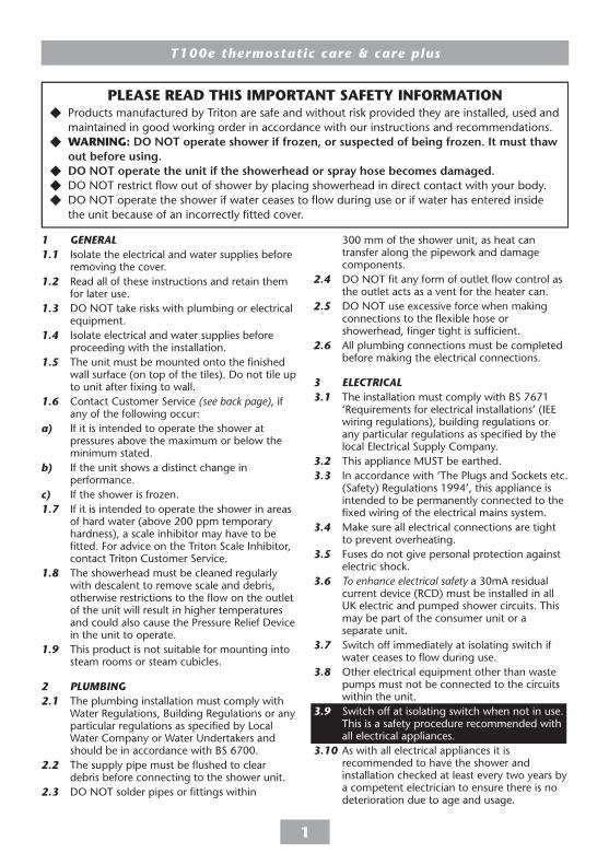
GENERALIsolate the electrical and water supplies before removing the cover.Read all of these instructions and retain them for later use.DO NOT take risks with plumbing or electrical equipment.Isolate electrical and water supplies before proceeding with the installation.The unit must be mounted onto the finished wall surface (on top of the tiles). Do not tile up to unit after fixing to wall.Contact Customer Service (see back page), if any of the following occur:If it is intended to operate the shower at pressures above the maximum or below the minimum stated.If the unit shows a distinct change in performance.If the shower is frozen.If it is intended to operate the shower in areas of hard water (above 200 ppm temporary hardness), a scale inhibitor may have to be fitted. For advice on the Triton Scale Inhibitor, contact Triton Customer Service.The showerhead must be cleaned regularly with descalent to remove scale and debris, otherwise restrictions to the flow on the outlet of the unit will result in higher temperatures and could also cause the Pressure Relief Device in the unit to operate.This product is not suitable for mounting into steam rooms or steam cubicles.
PLUMBINGThe plumbing installation must comply with Water Regulations, Building Regulations or any particular regulations as specified by Local Water Company or Water Undertakers and should be in accordance with BS 6700.The supply pipe must be flushed to clear debris before connecting to the shower unit.DO NOT solder pipes or fittings within
300 mm of the shower unit, as heat can transfer along the pipework and damage components.DO NOT fit any form of outlet flow control as the outlet acts as a vent for the heater can.DO NOT use excessive force when making connections to the flexible hose or showerhead, finger tight is sufficient.All plumbing connections must be completed before making the electrical connections.
ELECTRICALThe installation must comply with BS 7671 ‘Requirements for electrical installations’ (IEE wiring regulations), building regulations or any particular regulations as specified by the local Electrical Supply Company.This appliance MUST be earthed.In accordance with ‘The Plugs and Sockets etc. (Safety) Regulations 1994’, this appliance is intended to be permanently connected to the fixed wiring of the electrical mains system.Make sure all electrical connections are tight to prevent overheating.Fuses do not give personal protection against electric shock.To enhance electrical safety a 30mA residual current device (RCD) must be installed in all UK electric and pumped shower circuits. This may be part of the consumer unit or a separate unit.Switch off immediately at isolating switch if water ceases to flow during use.Other electrical equipment other than waste pumps must not be connected to the circuits within the unit.Switch off at isolating switch when not in use. This is a safety procedure recommended with all electrical appliances.As with all electrical appliances it is recommended to have the shower and installation checked at least every two years by a competent electrician to ensure there is no deterioration due to age and usage.
�
�
���
Products manufactured by Triton are safe and without risk provided they are installed, used and maintained in good working order in accordance with our instructions and recommendations.WARNING: DO NOT operate shower if frozen, or suspected of being frozen. It must thaw out before using.DO NOT operate the unit if the showerhead or spray hose becomes damaged.DO NOT restrict flow out of shower by placing showerhead in direct contact with your body.DO NOT operate the shower if water ceases to flow during use or if water has entered inside the unit because of an incorrectly fitted cover.
PLEASE READ THIS IMPORTANT SAFETY INFORMATION
T100e thermostatic care & care plus
�
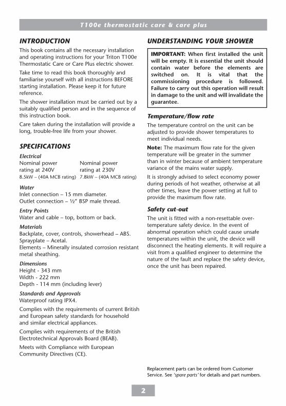
This book contains all the necessary installation and operating instructions for your Triton T100e Thermostatic Care or Care Plus electric shower.
Take time to read this book thoroughly and familiarise yourself with all instructions bEFORE starting installation. Please keep it for future reference.
The shower installation must be carried out by a suitably qualified person and in the sequence of this instruction book.
Care taken during the installation will provide a long, trouble-free life from your shower.
SpecificationsSPECIFICATIONSElectrical Nominal power Nominal power rating at 240V rating at 230V 8.5kW – (40A MCb rating) 7.8kW – (40A MCb rating)
Water Inlet connection – 15 mm diameter. Outlet connection – ½” bSP male thread.
Entry Points Water and cable – top, bottom or back.
Materials backplate, cover, controls, showerhead – AbS. Sprayplate – Acetal. Elements – Minerally insulated corrosion resistant metal sheathing.
Dimensions Height - 343 mm Width - 222 mm Depth - 114 mm (including lever)
Standards and Approvals Waterproof rating IPX4.
Complies with the requirements of current british and European safety standards for household and similar electrical appliances.
Complies with requirements of the british Electrotechnical Approvals board (bEAb).
Meets with Compliance with European Community Directives (CE).
I-001-A
IMPORTANT: When first installed the unit will be empty. It is essential the unit should contain water before the elements are switched on. It is vital that the commissioning procedure is followed. Failure to carry out this operation will result in damage to the unit and will invalidate the guarantee.
Temperature/flow rateThe temperature control on the unit can be adjusted to provide shower temperatures to meet individual needs.
Note: The maximum flow rate for the given temperature will be greater in the summer than in winter because of ambient temperature variance of the mains water supply.
It is strongly advised to select economy power during periods of hot weather, otherwise at all other times, leave the power setting at full to provide the maximum flow rate.
Safety cut-outThe unit is fitted with a non-resettable over-temperature safety device. In the event of abnormal operation which could cause unsafe temperatures within the unit, the device will disconnect the heating elements. It will require a visit from a qualified engineer to determine the nature of the fault and replace the safety device, once the unit has been repaired.
IntroductionINTRODUCTION
Y-003-AReplacement parts can be ordered from Customer Service. See ‘spare parts’ for details and part numbers.
Understanding your showerUNDERSTANDING YOUR SHOWER
T100e thermostatic care & care plus
�
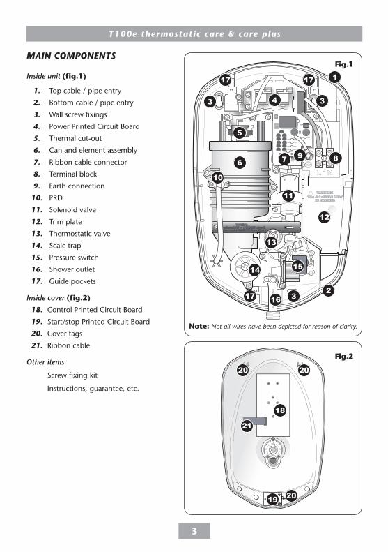
Main componentsMAIN COMPONENTS
LL NN
17 1
2
17
3 3
3
4
5
6
10
12
879
11
14
13
15
1617
Inside unit (fig.�)
1. Top cable / pipe entry
�. bottom cable / pipe entry
3. Wall screw fixings
4. Power Printed Circuit board
5. Thermal cut-out
6. Can and element assembly
7. Ribbon cable connector
8. Terminal block
9. Earth connection
10. PRD
11. Solenoid valve
12. Trim plate
13. Thermostatic valve
14. Scale trap
15. Pressure switch
16. Shower outlet
17. Guide pockets
Inside cover (fig.�)
18. Control Printed Circuit board
19. Start/stop Printed Circuit board
20. Cover tags
21. Ribbon cable
Other items
Screw fixing kit
Instructions, guarantee, etc.
20 20
2019
21
18
Fig.�
Note: Not all wires have been depicted for reason of clarity.
Fig.�
1
2
3 3
3
4
5
6 7 89
10
11
12
13
14 15
1617
17 17
18
19 20
20 20
21
T100e thermostatic care & care plus
�
Meter Incomingsupplyfuse
Metertails
Consumerunit
Pull cordisolating switch
Showerunit
Fuse orMCB
RCD(can be part ofconsumer unit)
80A or 100Amain switch
Shepperton Park,Triton Road, Nuneaton,
Warwickshire, CV11 4NR
Table A
MCB
30/32A
32A
40A
40A
40A
40/45A
45A
cartridgefuse
30A
35A
35A
45A
45A
45A
45A
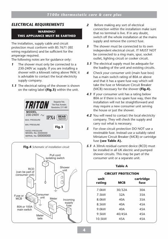
unit rating
7.0kW
7.5kW
8.0kW
8.5kW
9.0kW
9.5kW
10.5kW
CIRCUIT PROTECTION
Fig.� Schematic of installation circuit
Fig.�
W-006-AWARNING!THIS APPLIANCE MUST BE EARTHED
E-002-A
ELECTRICAL REQUIREMENTS
The installation, supply cable and circuit protection must conform with BS 7671 (IEE wiring regulations) and be sufficient for the amperage required.The following notes are for guidance only:
1 The shower must only be connected to a 230-240V ac supply. If you are installing a shower with a kilowatt rating above 9kW, it is advisable to contact the local electricity supply company.
1.1 The electrical rating of the shower is shown on the rating label (Fig.3) within the unit.
2 Before making any sort of electrical connection within the installation make sure that no terminal is live. If in any doubt, switch off the whole installation at the mains supply and remove the correct fuse.
3 The shower must be connected to its own independent electrical circuit. IT MUST NOT be connected to a ring main, spur, socket outlet, lighting circuit or cooker circuit.
3.1 The electrical supply must be adequate for the loading of the unit and existing circuits.
4 Check your consumer unit (main fuse box) has a main switch rating of 80A or above and that it has a spare fuse way which will take the fuse or Miniature Circuit Breaker (MCB) necessary for the shower (Fig.4).
4.1 If your consumer unit has a rating below 80A or if there is no spare fuse way, then the installation will not be straightforward and may require a new consumer unit serving the house or just the shower.
4.2 You will need to contact the local electricity company. They will check the supply and carry out what is necessary.
5 For close circuit protection DO NOT use a rewireable fuse. Instead use a suitably rated Miniature Circuit Breaker (MCB) or cartridge fuse (see Table A).
5.1 A 30mA residual current device (RCD) must be installed in all UK electric and pumped shower circuits. This may be part of the consumer unit or a separate unit.
6 A 45 amp double pole isolating switch with a minimum contact gap of 3 mm in both poles must be incorporated in the circuit.
6.1 It must have a mechanical indicator showing when the switch is in the OFF position, and the wiring must be connected to the switch without the use of a plug or socket outlet.
6.2 The switch must be accessible and clearly identifiable, but out of reach of a person using a fixed bath or shower, except for the cord of a cord operated switch, and should be placed so that it is not possible to touch the switch body while standing in a bath or shower cubicle. It should be readily accessible to switch off after using the shower.
7 Where shower cubicles are located in any rooms other than bathrooms, all socket outlets in those rooms must be protected by a 30mA RCD.
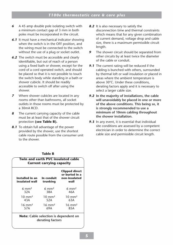
8 The current carrying capacity of the cable must be at least that of the shower circuit protection (see Table B).
8.1 To obtain full advantage of the power provided by the shower, use the shortest cable route possible from the consumer unit to the shower.
8.2 It is also necessary to satisfy the disconnection time and thermal constraints which means that for any given combination of current demand, voltage drop and cable size, there is a maximum permissible circuit length.
9 The shower circuit should be separated from other circuits by at least twice the diameter of the cable or conduit.
9.1 The current rating will be reduced if the cabling is bunched with others, surrounded by thermal loft or wall insulation or placed in areas where the ambient temperature is above 30°C. Under these conditions, derating factors apply and it is necessary to select a larger cable size.
9.2 In the majority of installations, the cable will unavoidably be placed in one or more of the above conditions. This being so, it is strongly recommended to use a minimum of 10mm cabling throughout the shower installation.
9.3 In any event, it is essential that individual site conditions are assessed by a competent electrician in order to determine the correct cable size and permissible circuit length.
E-002-A
ELECTRICAL REQUIREMENTS
The installation, supply cable and circuit protection must conform with BS 7671 (IEE wiring regulations) and be sufficient for the amperage required.The following notes are for guidance only:
1 The shower must only be connected to a 230-240V ac supply. If you are installing a shower with a kilowatt rating above 9kW, it is advisable to contact the local electricity supply company.
1.1 The electrical rating of the shower is shown on the rating label (Fig.3) within the unit.
2 Before making any sort of electrical connection within the installation make sure that no terminal is live. If in any doubt, switch off the whole installation at the mains supply and remove the correct fuse.
3 The shower must be connected to its own independent electrical circuit. IT MUST NOT be connected to a ring main, spur, socket outlet, lighting circuit or cooker circuit.
3.1 The electrical supply must be adequate for the loading of the unit and existing circuits.
4 Check your consumer unit (main fuse box) has a main switch rating of 80A or above and that it has a spare fuse way which will take the fuse or Miniature Circuit Breaker (MCB) necessary for the shower (Fig.4).
4.1 If your consumer unit has a rating below 80A or if there is no spare fuse way, then the installation will not be straightforward and may require a new consumer unit serving the house or just the shower.
4.2 You will need to contact the local electricity company. They will check the supply and carry out what is necessary.
5 For close circuit protection DO NOT use a rewireable fuse. Instead use a suitably rated Miniature Circuit Breaker (MCB) or cartridge fuse (see Table A).
5.1 A 30mA residual current device (RCD) must be installed in all UK electric and pumped shower circuits. This may be part of the consumer unit or a separate unit.
6 A 45 amp double pole isolating switch with a minimum contact gap of 3 mm in both poles must be incorporated in the circuit.
6.1 It must have a mechanical indicator showing when the switch is in the OFF position, and the wiring must be connected to the switch without the use of a plug or socket outlet.
6.2 The switch must be accessible and clearly identifiable, but out of reach of a person using a fixed bath or shower, except for the cord of a cord operated switch, and should be placed so that it is not possible to touch the switch body while standing in a bath or shower cubicle. It should be readily accessible to switch off after using the shower.
7 Where shower cubicles are located in any rooms other than bathrooms, all socket outlets in those rooms must be protected by a 30mA RCD.
8 The current carrying capacity of the cable must be at least that of the shower circuit protection (see Table B).
8.1 To obtain full advantage of the power provided by the shower, use the shortest cable route possible from the consumer unit to the shower.
8.2 It is also necessary to satisfy the disconnection time and thermal constraints which means that for any given combination of current demand, voltage drop and cable size, there is a maximum permissible circuit length.
9 The shower circuit should be separated from other circuits by at least twice the diameter of the cable or conduit.
9.1 The current rating will be reduced if the cabling is bunched with others, surrounded by thermal loft or wall insulation or placed in areas where the ambient temperature is above 30°C. Under these conditions, derating factors apply and it is necessary to select a larger cable size.
9.2 In the majority of installations, the cable will unavoidably be placed in one or more of the above conditions. This being so, it is strongly recommended to use a minimum of 10mm cabling throughout the shower installation.
9.3 In any event, it is essential that individual site conditions are assessed by a competent electrician in order to determine the correct cable size and permissible circuit length.
T100e thermostatic care & care plus
�
Table B
Note: Cable selection is dependent on derating factors
Twin and earth PVC insulated cableCurrent carrying capacity
In conduittrunking
6 mm²38A
10 mm²52A
16 mm²69A
Installed in an insulated wall
6 mm²32A
10 mm²43A
16 mm²57A
Clipped director buried in a non-insulated
wall
6 mm²46A
10 mm²63A
16 mm²85A
E-002-A
ELECTRICAL REQUIREMENTS
The installation, supply cable and circuit protection must conform with BS 7671 (IEE wiring regulations) and be sufficient for the amperage required.The following notes are for guidance only:
1 The shower must only be connected to a 230-240V ac supply. If you are installing a shower with a kilowatt rating above 9kW, it is advisable to contact the local electricity supply company.
1.1 The electrical rating of the shower is shown on the rating label (Fig.3) within the unit.
2 Before making any sort of electrical connection within the installation make sure that no terminal is live. If in any doubt, switch off the whole installation at the mains supply and remove the correct fuse.
3 The shower must be connected to its own independent electrical circuit. IT MUST NOT be connected to a ring main, spur, socket outlet, lighting circuit or cooker circuit.
3.1 The electrical supply must be adequate for the loading of the unit and existing circuits.
4 Check your consumer unit (main fuse box) has a main switch rating of 80A or above and that it has a spare fuse way which will take the fuse or Miniature Circuit Breaker (MCB) necessary for the shower (Fig.4).
4.1 If your consumer unit has a rating below 80A or if there is no spare fuse way, then the installation will not be straightforward and may require a new consumer unit serving the house or just the shower.
4.2 You will need to contact the local electricity company. They will check the supply and carry out what is necessary.
5 For close circuit protection DO NOT use a rewireable fuse. Instead use a suitably rated Miniature Circuit Breaker (MCB) or cartridge fuse (see Table A).
5.1 A 30mA residual current device (RCD) must be installed in all UK electric and pumped shower circuits. This may be part of the consumer unit or a separate unit.
6 A 45 amp double pole isolating switch with a minimum contact gap of 3 mm in both poles must be incorporated in the circuit.
6.1 It must have a mechanical indicator showing when the switch is in the OFF position, and the wiring must be connected to the switch without the use of a plug or socket outlet.
6.2 The switch must be accessible and clearly identifiable, but out of reach of a person using a fixed bath or shower, except for the cord of a cord operated switch, and should be placed so that it is not possible to touch the switch body while standing in a bath or shower cubicle. It should be readily accessible to switch off after using the shower.
7 Where shower cubicles are located in any rooms other than bathrooms, all socket outlets in those rooms must be protected by a 30mA RCD.
8 The current carrying capacity of the cable must be at least that of the shower circuit protection (see Table B).
8.1 To obtain full advantage of the power provided by the shower, use the shortest cable route possible from the consumer unit to the shower.
8.2 It is also necessary to satisfy the disconnection time and thermal constraints which means that for any given combination of current demand, voltage drop and cable size, there is a maximum permissible circuit length.
9 The shower circuit should be separated from other circuits by at least twice the diameter of the cable or conduit.
9.1 The current rating will be reduced if the cabling is bunched with others, surrounded by thermal loft or wall insulation or placed in areas where the ambient temperature is above 30°C. Under these conditions, derating factors apply and it is necessary to select a larger cable size.
9.2 In the majority of installations, the cable will unavoidably be placed in one or more of the above conditions. This being so, it is strongly recommended to use a minimum of 10mm cabling throughout the shower installation.
9.3 In any event, it is essential that individual site conditions are assessed by a competent electrician in order to determine the correct cable size and permissible circuit length.
T100e thermostatic care & care plus
�
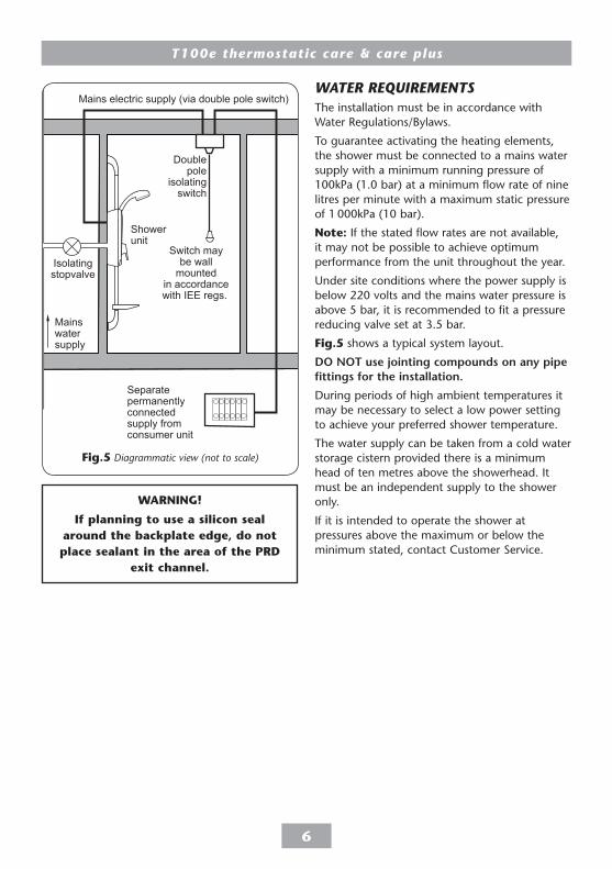
The installation must be in accordance with Water Regulations/bylaws.
To guarantee activating the heating elements, the shower must be connected to a mains water supply with a minimum running pressure of 100kPa (1.0 bar) at a minimum flow rate of nine litres per minute with a maximum static pressure of 1 000kPa (10 bar).
Note: If the stated flow rates are not available, it may not be possible to achieve optimum performance from the unit throughout the year.
Under site conditions where the power supply is below 220 volts and the mains water pressure is above 5 bar, it is recommended to fit a pressure reducing valve set at 3.5 bar.
Fig.� shows a typical system layout.
Do not use jointing compounds on any pipe fittings for the installation.
During periods of high ambient temperatures it may be necessary to select a low power setting to achieve your preferred shower temperature.
The water supply can be taken from a cold water storage cistern provided there is a minimum head of ten metres above the showerhead. It must be an independent supply to the shower only.
If it is intended to operate the shower at pressures above the maximum or below the minimum stated, contact Customer Service.
Isolatingstopvalve
Mainswatersupply
Showerunit
Switch maybe wall
mountedin accordancewith IEE regs.
Mains electric supply (via double pole switch)
Doublepole
isolatingswitch
Separatepermanentlyconnectedsupply fromconsumer unit
WArNINg!
If planning to use a silicon seal around the backplate edge, do not place sealant in the area of the PrD
exit channel.
Fig.� Diagrammatic view (not to scale)
Water requirementsWATER REQUIREMENTS
T100e thermostatic care & care plus
�
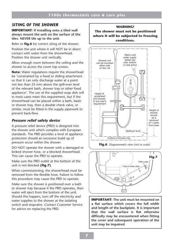
ImPorTANT: If installing onto a tiled wall always mount the unit on the surface of the tiles. nEVER tile up to the unit.
Refer to fig.� for correct siting of the shower.
Position the unit where it will NOT be in direct contact with water from the showerhead. Position the shower unit vertically.
Allow enough room between the ceiling and the shower to access the cover top screws.
Note: Water regulations require the showerhead be ‘constrained by a fixed or sliding attachment so that it can only discharge water at a point not less than 25 mm above the spill-over level of the relevant bath, shower tray or other fixed appliance’. The use of the supplied soap dish will in most cases meet this requirement, but if the showerhead can be placed within a bath, basin or shower tray, then a double check valve, or similar, must be fitted in the supply pipework to prevent back-flow.
Pressure relief safety deviceA pressure relief device (PRD) is designed into the shower unit which complies with European standards. The PRD provides a level of appliance protection should an excessive build up of pressure occur within the shower.
DO NOT operate the shower with a damaged or kinked shower hose, or a blocked showerhead. This can cause the PRD to operate.
Make sure the PRD outlet at the bottom of the unit is not blocked (fig.�).
When commissioning, the showerhead must be removed from the flexible hose. Failure to follow this procedure may cause the PRD to operate.
Make sure the shower is positioned over a bath or shower tray because if the PRD operates, then water will eject from the bottom of the unit. Should this happen, turn off the electricity and water supplies to the shower at the isolating switch and stopvalve. Contact Customer Service for advice on replacing the PRD.
Outline of shower tray
Mains coldwater supply (either top,
side, bottom or rear entry)
Shower unitcan be mounted
either sideof riser rail
Height ofshowershouldbe a
minimumof 1 metrefrom base
Spillover level
Height of sprayhead
and shower to suit user'srequirement
Area to keep clear
PRD outlet
Fig.� Diagrammatic view (not to scale)
Fig.�
W-008-AWARNING!
The shower must not be positioned where it will be subjected to freezing
conditions.
I-002-A
IMPORTANT: The unit must be mounted on a flat surface which covers the full width and length of the backplate. It is important that the wall surface is flat otherwise difficulty may be encountered when fitting the cover and subsequent operation of the unit may be impaired.
Siting of the showerSITING OF THE SHOWER
T100e thermostatic care & care plus
�
W-005-A
WARNING!Check there are no hidden cables or pipes before drilling holes for wall
plugs. Use great care when using power tools near water. The use of a residual current device (RCD) is recommended.
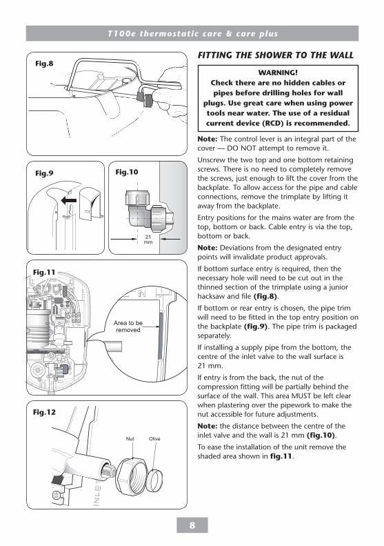
Note: The control lever is an integral part of the cover — DO NOT attempt to remove it.
Unscrew the two top and one bottom retaining screws. There is no need to completely remove the screws, just enough to lift the cover from the backplate. To allow access for the pipe and cable connections, remove the trimplate by lifting it away from the backplate.
Entry positions for the mains water are from the top, bottom or back. Cable entry is via the top, bottom or back.
Note: Deviations from the designated entry points will invalidate product approvals.
If bottom surface entry is required, then the necessary hole will need to be cut out in the thinned section of the trimplate using a junior hacksaw and file (fig.�).
If bottom or rear entry is chosen, the pipe trim will need to be fitted in the top entry position on the backplate (fig.9). The pipe trim is packaged separately.
If installing a supply pipe from the bottom, the centre of the inlet valve to the wall surface is 21 mm.
If entry is from the back, the nut of the compression fitting will be partially behind the surface of the wall. This area MUST be left clear when plastering over the pipework to make the nut accessible for future adjustments.
Note: the distance between the centre of the inlet valve and the wall is 21 mm (fig.�0).
To ease the installation of the unit remove the shaded area shown in fig.��.
Fig.�
Fig.9
21mm
Fig.�0
INLE
T
LL NN
INLE
T
NN
Area to beremoved
Fig.��
OliveNut
Fig.��
Fitting the shower to the wallFITTING THE SHOWER TO THE WALL

T100e thermostatic care & care plus
9
Slide the compression nut and olive onto the unit inlet pipe. Make sure the inlet filter is in place before attempting to fit onto the elbow connector (fig.��).
Turn the unit at an angle similar to that shown in fig.��. This will allow easier access for fitting the inlet pipe onto the elbow connector.
Fit the unit, taking care to make sure that the inlet pipe is connected to the elbow. Once the inlet pipe is located, carefully turn the unit anti-clockwise until it is level and push gently into place onto the elbow (fig,��).
After choosing the site for the shower, use the backplate as a template (fig.��) and mark the three fixing holes.
Remove the unit. Drill and plug to suit the fixing screws supplied. (The wall plugs provided are suitable for most brick walls — use an appropriate masonry drill. If the wall is plasterboard or soft building block, you must use suitable wall plugs and an appropriate drill bit).
Secure the unit in place using the screws supplied. Do not fully tighten the screws at this stage, as the fixing holes are elongated for out of square adjustment after the plumbing connections has been completed.
. . . . . .. . . . . . . . . . . .. . . . . .
LL NN
. . . . . .. . . . . . . . . . . .. . . . . .
INLE
TIN
LET
Slide inlet pipe intoelbow connector
at an angle
. . . . . .. . . . . . . . . . . .. . . . . .
LL NN
. . . . . .. . . . . . . . . . . .. . . . . .
INLE
TIN
LET
Fig.��
Fig.��
LL NN
Fig.��
T100e thermostatic care & care plus
�0
Plumbing to be carried out before wiring
DO NOT use jointing compounds on any pipe fittings for the installation.
DO NOT solder fittings near the shower unit as heat can transfer along the pipework and damage components.
Compression fittings MUST be used to connect to the inlet of the shower.
Note: An additional stopvalve (complying with Water Regulations) MUST be fitted in the mains water supply to the shower as an independent means of isolating the water supply should maintenance or servicing be necessary.
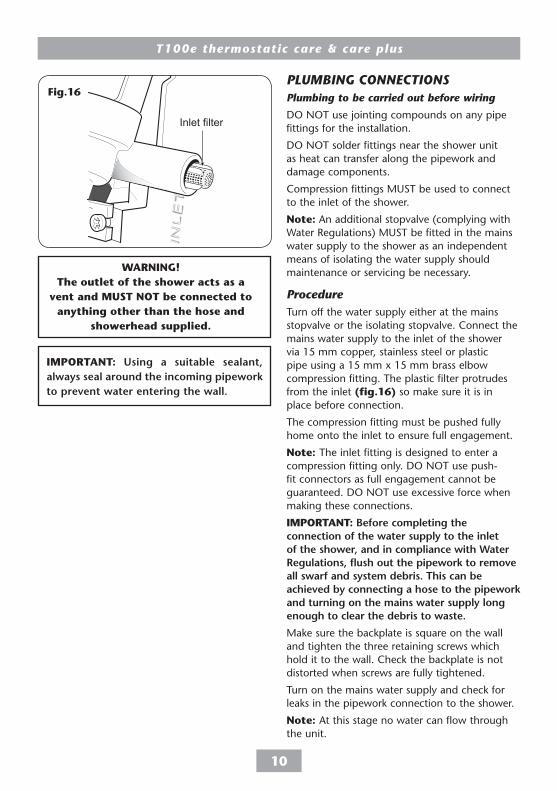
ProcedureTurn off the water supply either at the mains stopvalve or the isolating stopvalve. Connect the mains water supply to the inlet of the shower via 15 mm copper, stainless steel or plastic pipe using a 15 mm x 15 mm brass elbow compression fitting. The plastic filter protrudes from the inlet (fig.��) so make sure it is in place before connection.
The compression fitting must be pushed fully home onto the inlet to ensure full engagement.
Note: The inlet fitting is designed to enter a compression fitting only. DO NOT use push-fit connectors as full engagement cannot be guaranteed. DO NOT use excessive force when making these connections.
ImPorTANT: Before completing the connection of the water supply to the inlet of the shower, and in compliance with Water Regulations, flush out the pipework to remove all swarf and system debris. this can be achieved by connecting a hose to the pipework and turning on the mains water supply long enough to clear the debris to waste.
Make sure the backplate is square on the wall and tighten the three retaining screws which hold it to the wall. Check the backplate is not distorted when screws are fully tightened.
Turn on the mains water supply and check for leaks in the pipework connection to the shower.
Note: At this stage no water can flow through the unit.
Inlet filter
Fig.��
ImPorTANT: Using a suitable sealant, always seal around the incoming pipework to prevent water entering the wall.
Plumbing connectionsPLUMBING CONNECTIONS
W-004-A
WARNING!The outlet of the shower acts as a
vent and MUST NOT be connected to anything other than the hose and
showerhead supplied.
T100e thermostatic care & care plus
��
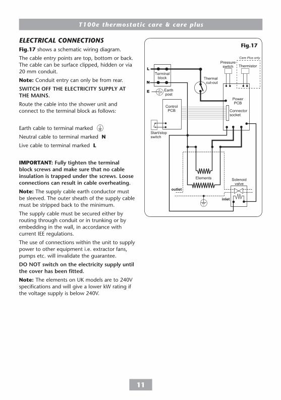
Fig.�� shows a schematic wiring diagram.
The cable entry points are top, bottom or back. The cable can be surface clipped, hidden or via 20 mm conduit.
Note: Conduit entry can only be from rear.
SWItch off thE ElEctRIcIty SUpply at thE maInS.
Route the cable into the shower unit and connect to the terminal block as follows:
Earth cable to terminal marked
Neutral cable to terminal marked N
Live cable to terminal marked L
ImPorTANT: fully tighten the terminal block screws and make sure that no cable insulation is trapped under the screws. loose connections can result in cable overheating.
Note: The supply cable earth conductor must be sleeved. The outer sheath of the supply cable must be stripped back to the minimum.
The supply cable must be secured either by routing through conduit or in trunking or by embedding in the wall, in accordance with current IEE regulations.
The use of connections within the unit to supply power to other equipment i.e. extractor fans, pumps etc. will invalidate the guarantee.
Do not switch on the electricity supply until the cover has been fitted.
Note: The elements on UK models are to 240V specifications and will give a lower kW rating if the voltage supply is below 240V.
L
N
E
Start/stopswitch
ControlPCB
PowerPCB
Connectorsocket
Terminalblock Thermal
cut-out
Pressureswitch Thermistor
Earthpost
inlet
Solenoidvalve
outlet
Elements
Care Plus only
Fig.��Electrical connectionsELECTRICAL CONNECTIONS
T100e thermostatic care & care plus
��
W-001-A
WARNING!Before normal operation of the
shower, it is essential the following commissioning procedure is completed
correctly.
The first operation of the shower is intended to flush out any remaining system debris, to make sure that water is purged through the unit and that the heater unit contains water before the elements are switched on.
Refit the trimplate by carefully guiding into the locating slots in the backplate.
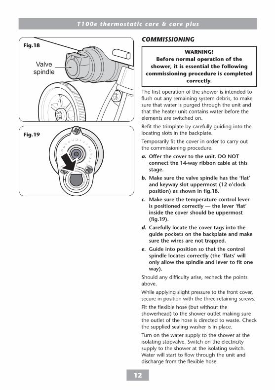
Temporarily fit the cover in order to carry out the commissioning procedure.
a. offer the cover to the unit. Do not connect the 14-way ribbon cable at this stage.
b. make sure the valve spindle has the ‘flat’ and keyway slot uppermost (12 o’clock position) as shown in fig.18.
c. make sure the temperature control lever is positioned correctly — the lever ‘flat’ inside the cover should be uppermost (fig.19).
d. carefully locate the cover tags into the guide pockets on the backplate and make sure the wires are not trapped.
e. Guide into position so that the control spindle locates correctly (the ‘flats’ will only allow the spindle and lever to fit one way).
Should any difficulty arise, recheck the points above.
While applying slight pressure to the front cover, secure in position with the three retaining screws.
Fit the flexible hose (but without the showerhead) to the shower outlet making sure the outlet of the hose is directed to waste. Check the supplied sealing washer is in place.
Turn on the water supply to the shower at the isolating stopvalve. Switch on the electricity supply to the shower at the isolating switch. Water will start to flow through the unit and discharge from the flexible hose.
Valvespindle
Fig.��
Fig.�9
CommissioningCOMMISSIONING
T100e thermostatic care & care plus
��
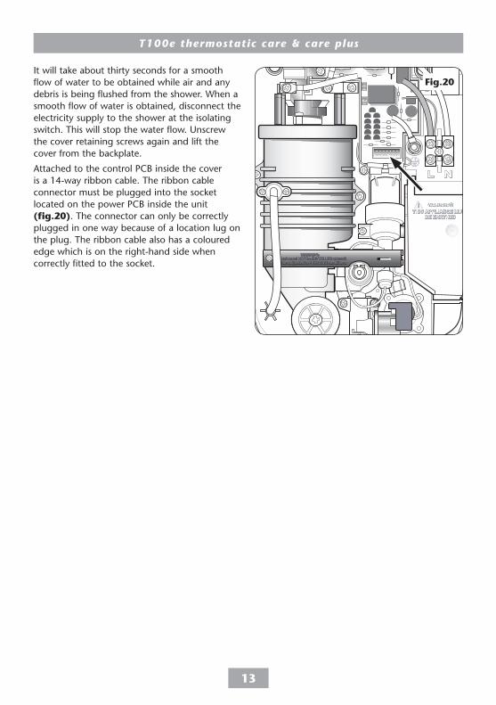
It will take about thirty seconds for a smooth flow of water to be obtained while air and any debris is being flushed from the shower. When a smooth flow of water is obtained, disconnect the electricity supply to the shower at the isolating switch. This will stop the water flow. Unscrew the cover retaining screws again and lift the cover from the backplate.
Attached to the control PCb inside the cover is a 14-way ribbon cable. The ribbon cable connector must be plugged into the socket located on the power PCb inside the unit (fig.�0). The connector can only be correctly plugged in one way because of a location lug on the plug. The ribbon cable also has a coloured edge which is on the right-hand side when correctly fitted to the socket.
LL NN
Fig.�0
T100e thermostatic care & care plus
��
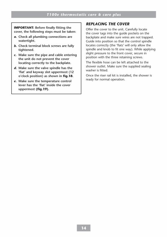
Offer the cover to the unit. Carefully locate the cover tags into the guide pockets on the backplate and make sure wires are not trapped. Guide into position so that the control spindle locates correctly (the ‘flats’ will only allow the spindle and knob to fit one way). While applying slight pressure to the front cover, secure in position with the three retaining screws.
The flexible hose can be left attached to the shower outlet. Make sure the supplied sealing washer is fitted.
Once the riser rail kit is installed, the shower is ready for normal operation.
ImPorTANT: Before finally fitting the cover, the following steps must be taken:
a. check all plumbing connections are watertight.
b. check terminal block screws are fully tightened.
c. make sure the pipe and cable entering the unit do not prevent the cover locating correctly to the backplate.
d. make sure the valve spindle has the ‘flat’ and keyway slot uppermost (12 o’clock position) as shown in fig.��.
e. make sure the temperature control lever has the ‘flat’ inside the cover uppermost (fig.�9).
Replacing the coverREPLACING THE COVER
T100e thermostatic care & care plus
��
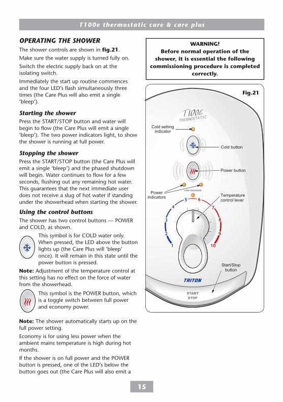
The shower controls are shown in fig.��.
Make sure the water supply is turned fully on.
Switch the electric supply back on at the isolating switch.
Immediately the start up routine commences and the four LED’s flash simultaneously three times (the Care Plus will also emit a single ‘bleep’).
Starting the showerPress the START/STOP button and water will begin to flow (the Care Plus will emit a single ‘bleep’). The two power indicators light, to show the shower is running at full power.
Stopping the showerPress the START/STOP button (the Care Plus will emit a single ‘bleep’) and the phased shutdown will begin. Water continues to flow for a few seconds, flushing out any remaining hot water. This guarantees that the next immediate user does not receive a slug of hot water if standing under the showerhead when starting the shower.
Using the control buttonsThe shower has two control buttons — POWER and COLD, as shown.
This symbol is for COLD water only. When pressed, the LED above the button lights up (the Care Plus will ‘bleep’ once). It will remain in this state until the power button is pressed.
Note: Adjustment of the temperature control at this setting has no effect on the force of water from the showerhead.
This symbol is the POWER button, which is a toggle switch between full power and economy power.
Note: The shower automatically starts up on the full power setting.
Economy is for using less power when the ambient mains temperature is high during hot months.
If the shower is on full power and the POWER button is pressed, one of the LED’s below the button goes out (the Care Plus will also emit a
Cold button
Power button
Temperaturecontrol lever
Start/Stopbutton
Cold settingindicator
Powerindicators
Fig.��
W-001-A
WARNING!Before normal operation of the
shower, it is essential the following commissioning procedure is completed
correctly.
Operating the showerOPERATING THE SHOWER
T100e thermostatic care & care plus
��
single ‘bleep’). During this time, the flow rate decreases to try to achieve the same temperature as before.
Note: If the temperature setting was high at full power, then it will not be possible to obtain the same temperature as before on the economy setting. The shower will attempt to provide the highest temperature at the best flow rate.
Adjust the temperature via the temperature control.
Note: If the stated flow rate required for the unit cannot be met due to low water pressure, it will be necessary to operate the shower on economy power during hot months because of flow rate limitations entering the unit.
If the shower is on economy power or the cold setting and the power button is pressed, both LED’s will light up (and the Care Plus will emit a single ‘bleep’). During this time, the flow rate increases to achieve the same temperature as before or to correspond to the current temperature control position.
It is advisable to select full power at all times, except during periods of hot weather.
Adjusting the shower temperature
The showering temperature is varied by turning the temperature control which changes the mix of hot water coming from the heater can and the incoming cold water.
On the display circumference are ten marked outer segments which represent the total angular movement of the temperature control.
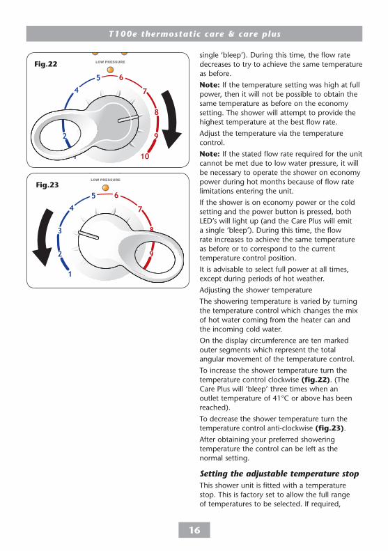
To increase the shower temperature turn the temperature control clockwise (fig.��). (The Care Plus will ‘bleep’ three times when an outlet temperature of 41°C or above has been reached).
To decrease the shower temperature turn the temperature control anti-clockwise (fig.��).
After obtaining your preferred showering temperature the control can be left as the normal setting.
Setting the adjustable temperature stopThis shower unit is fitted with a temperature stop. This is factory set to allow the full range of temperatures to be selected. If required,
Fig.��
Fig.��
T100e thermostatic care & care plus
��
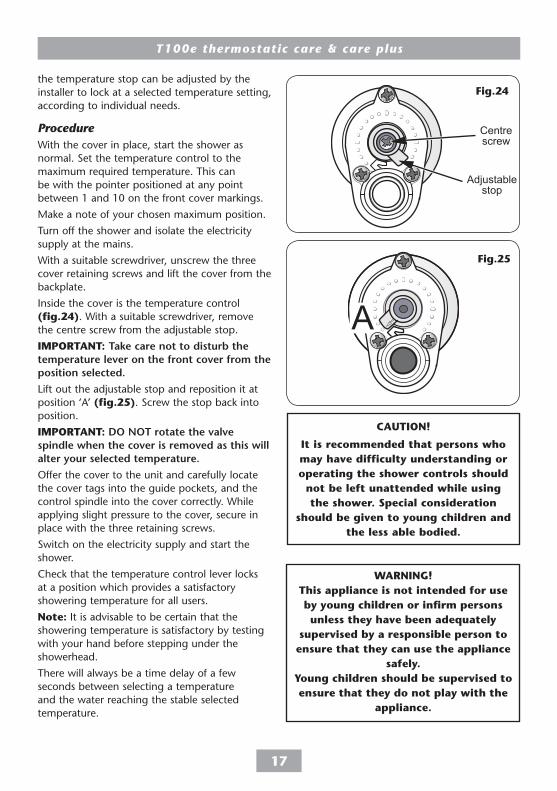
the temperature stop can be adjusted by the installer to lock at a selected temperature setting, according to individual needs.
ProcedureWith the cover in place, start the shower as normal. Set the temperature control to the maximum required temperature. This can be with the pointer positioned at any point between 1 and 10 on the front cover markings.
Make a note of your chosen maximum position.
Turn off the shower and isolate the electricity supply at the mains.
With a suitable screwdriver, unscrew the three cover retaining screws and lift the cover from the backplate.
Inside the cover is the temperature control (fig.��). With a suitable screwdriver, remove the centre screw from the adjustable stop.
ImPorTANT: take care not to disturb the temperature lever on the front cover from the position selected.
Lift out the adjustable stop and reposition it at position ‘A’ (fig.��). Screw the stop back into position.
ImPorTANT: Do not rotate the valve spindle when the cover is removed as this will alter your selected temperature.
Offer the cover to the unit and carefully locate the cover tags into the guide pockets, and the control spindle into the cover correctly. While applying slight pressure to the cover, secure in place with the three retaining screws.
Switch on the electricity supply and start the shower.
Check that the temperature control lever locks at a position which provides a satisfactory showering temperature for all users.
Note: It is advisable to be certain that the showering temperature is satisfactory by testing with your hand before stepping under the showerhead.
There will always be a time delay of a few seconds between selecting a temperature and the water reaching the stable selected temperature.
Adjustablestop
Centrescrew
Fig.��
A
Fig.��
CAuTIoN!
It is recommended that persons who may have difficulty understanding or operating the shower controls should
not be left unattended while using the shower. Special consideration
should be given to young children and the less able bodied.
W-020-A
WARNING!This appliance is not intended for use by young children or infirm persons unless they have been adequately
supervised by a responsible person to ensure that they can use the appliance
safely.Young children should be supervised to ensure that they do not play with the
appliance.
T100e thermostatic care & care plus
��
Low pressureindicator
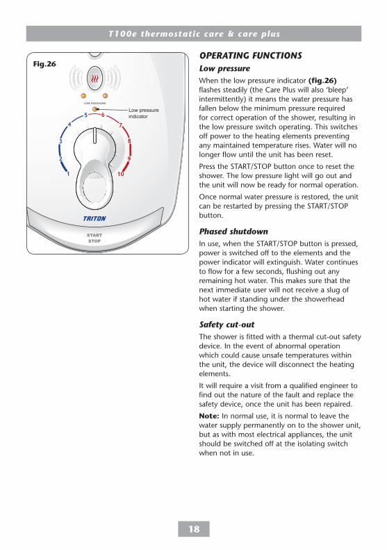
Low pressureWhen the low pressure indicator (fig.��) flashes steadily (the Care Plus will also ‘bleep’ intermittently) it means the water pressure has fallen below the minimum pressure required for correct operation of the shower, resulting in the low pressure switch operating. This switches off power to the heating elements preventing any maintained temperature rises. Water will no longer flow until the unit has been reset.
Press the START/STOP button once to reset the shower. The low pressure light will go out and the unit will now be ready for normal operation.
Once normal water pressure is restored, the unit can be restarted by pressing the START/STOP button.
Phased shutdownIn use, when the START/STOP button is pressed, power is switched off to the elements and the power indicator will extinguish. Water continues to flow for a few seconds, flushing out any remaining hot water. This makes sure that the next immediate user will not receive a slug of hot water if standing under the showerhead when starting the shower.
Safety cut-outThe shower is fitted with a thermal cut-out safety device. In the event of abnormal operation which could cause unsafe temperatures within the unit, the device will disconnect the heating elements.
It will require a visit from a qualified engineer to find out the nature of the fault and replace the safety device, once the unit has been repaired.
Note: In normal use, it is normal to leave the water supply permanently on to the shower unit, but as with most electrical appliances, the unit should be switched off at the isolating switch when not in use.
Fig.��Operating functionsOPERATING FUNCTIONS
T100e thermostatic care & care plus
�9
Cleaning the inlet filterCLEANING THE INLET FILTER
Instructions for installers and service engineers onlyINSTRUCTIONS FOR INSTALLERS AND SERVICE ENGINEERS ONLY
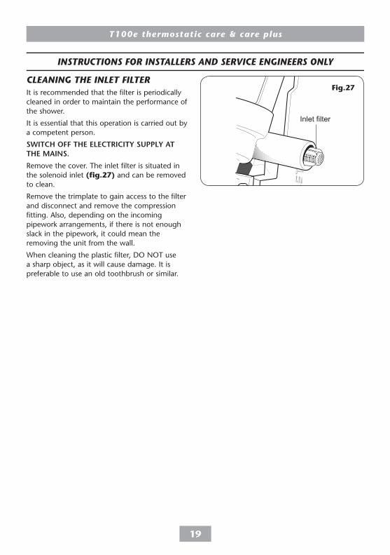
It is recommended that the filter is periodically cleaned in order to maintain the performance of the shower.
It is essential that this operation is carried out by a competent person.
SWItch off thE ElEctRIcIty SUpply at thE maInS.
Remove the cover. The inlet filter is situated in the solenoid inlet (fig.��) and can be removed to clean.
Remove the trimplate to gain access to the filter and disconnect and remove the compression fitting. Also, depending on the incoming pipework arrangements, if there is not enough slack in the pipework, it could mean the removing the unit from the wall.
When cleaning the plastic filter, DO NOT use a sharp object, as it will cause damage. It is preferable to use an old toothbrush or similar.
Inlet filter
Fig.��
T100e thermostatic care & care plus
�0
Cleaning the scale trapCLEANING THE SCALE TRAP
INSTRUCTIONS FOR INSTALLERS AND SERVICE ENGINEERS ONLY
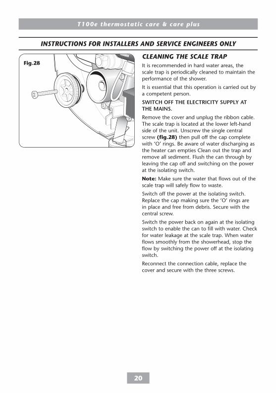
It is recommended in hard water areas, the scale trap is periodically cleaned to maintain the performance of the shower.
It is essential that this operation is carried out by a competent person.
SWItch off thE ElEctRIcIty SUpply at thE maInS.
Remove the cover and unplug the ribbon cable. The scale trap is located at the lower left-hand side of the unit. Unscrew the single central screw (fig.��) then pull off the cap complete with ‘O’ rings. be aware of water discharging as the heater can empties Clean out the trap and remove all sediment. Flush the can through by leaving the cap off and switching on the power at the isolating switch.
Note: Make sure the water that flows out of the scale trap will safely flow to waste.
Switch off the power at the isolating switch. Replace the cap making sure the ‘O’ rings are in place and free from debris. Secure with the central screw.
Switch the power back on again at the isolating switch to enable the can to fill with water. Check for water leakage at the scale trap. When water flows smoothly from the showerhead, stop the flow by switching the power off at the isolating switch.
Reconnect the connection cable, replace the cover and secure with the three screws.
Fig.��
T100e thermostatic care & care plus
��
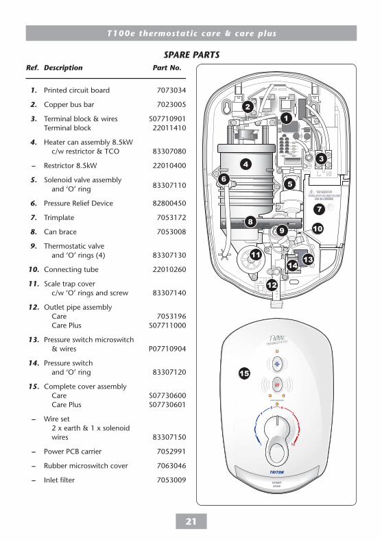
Spare parts SPARE PARTS
T00339
LL NN
1
2
34
5
7
9
6
12
1314
11
810
1. Printed circuit board 7073034
2. Copper bus bar 7023005
3. Terminal block & wires S07710901 Terminal block 22011410
4. Heater can assembly 8.5kW c/w restrictor & TCO 83307080
– Restrictor 8.5kW 22010400
5. Solenoid valve assembly and ‘O’ ring 83307110
6. Pressure Relief Device 82800450
7. Trimplate 7053172
8. Can brace 7053008
9. Thermostatic valve and ‘O’ rings (4) 83307130
10. Connecting tube 22010260
11. Scale trap cover c/w ‘O’ rings and screw 83307140
12. Outlet pipe assembly Care 7053196 Care Plus S07711000
13. Pressure switch microswitch & wires P07710904
14. Pressure switch and ‘O’ ring 83307120
15. Complete cover assembly Care S07730600 Care Plus S07730601
– Wire set 2 x earth & 1 x solenoid wires 83307150
– Power PCb carrier 7052991
– Rubber microswitch cover 7063046
– Inlet filter 7053009
Ref. Description Part No.
12
34
56
78
9 10
11
12
1314
15
T100e thermostatic care & care plus
��
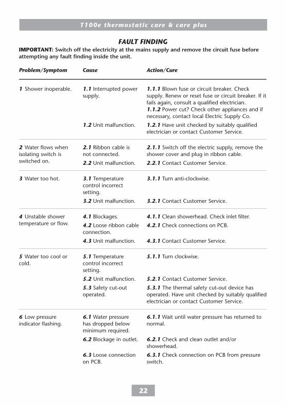
1 Shower inoperable.
2 Water flows when isolating switch is switched on.
3 Water too hot.
4 Unstable shower temperature or flow.
5 Water too cool or cold.
6 Low pressure indicator flashing.
1.1 Interrupted power supply.
1.2 Unit malfunction.
2.1 Ribbon cable is not connected.
2.2 Unit malfunction.
3.1 Temperature control incorrect setting.
3.2 Unit malfunction.
4.1 blockages.
4.2 Loose ribbon cable connection.
4.3 Unit malfunction.
5.1 Temperature control incorrect setting.
5.2 Unit malfunction.
5.3 Safety cut-out operated.
6.1 Water pressure has dropped below minimum required.
6.2 blockage in outlet.
6.3 Loose connection on PCb.
1.1.1 blown fuse or circuit breaker. Check supply. Renew or reset fuse or circuit breaker. If it fails again, consult a qualified electrician. 1.1.2 Power cut? Check other appliances and if necessary, contact local Electric Supply Co.
1.2.1 Have unit checked by suitably qualified electrician or contact Customer Service.
2.1.1 Switch off the electric supply, remove the shower cover and plug in ribbon cable.
2.2.1 Contact Customer Service.
3.1.1 Turn anti-clockwise.
3.2.1 Contact Customer Service.
4.1.1 Clean showerhead. Check inlet filter.
4.2.1 Check connections on PCb.
4.3.1 Contact Customer Service.
5.1.1 Turn clockwise.
5.2.1 Contact Customer Service.
5.3.1 The thermal safety cut-out device has operated. Have unit checked by suitably qualified electrician or contact Customer Service.
6.1.1 Wait until water pressure has returned to normal.
6.2.1 Check and clean outlet and/or showerhead.
6.3.1 Check connection on PCb from pressure switch.
Fault finding
FAULT FINDINGIMPORTANT: Switch off the electricity at the mains supply and remove the circuit fuse before attempting any fault finding inside the unit.
Problem/Symptom Cause Action/Cure
T100e thermostatic care & care plus
��
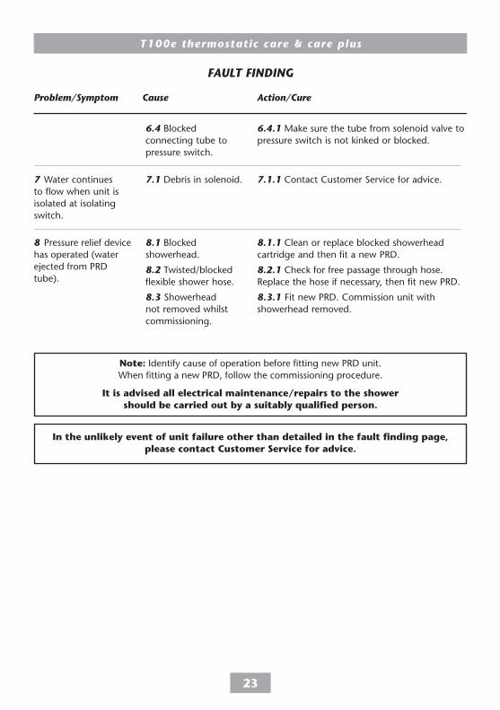
7 Water continues to flow when unit is isolated at isolating switch.
8 Pressure relief device has operated (water ejected from PRD tube).
6.4 blocked connecting tube to pressure switch.
7.1 Debris in solenoid.
8.1 blocked showerhead.
8.2 Twisted/blocked flexible shower hose.
8.3 Showerhead not removed whilst commissioning.
6.4.1 Make sure the tube from solenoid valve to pressure switch is not kinked or blocked.
7.1.1 Contact Customer Service for advice.
8.1.1 Clean or replace blocked showerhead cartridge and then fit a new PRD.
8.2.1 Check for free passage through hose. Replace the hose if necessary, then fit new PRD.
8.3.1 Fit new PRD. Commission unit with showerhead removed.
FAULT FINDING
Problem/Symptom Cause Action/Cure
Y-001-AIn the unlikely event of unit failure other than detailed in the fault finding page, please contact Customer Service for advice.
N-003-A
Note: Identify cause of operation before fitting new PRD unit.When fitting a new PRD, follow the commissioning procedure.
It is advised all electrical maintenance/repairs to the showershould be carried out by a suitably qualified person.

T100e thermostatic care & care plus
��

T100e thermostatic care & care plus
��
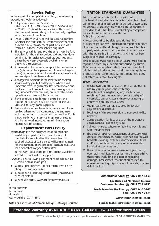
Service PolicyIn the event of a complaint occurring, the following procedure should be followed:1 Telephone Customer Service on
0870 067 3333 (0845 762 6591 in Scotland and in Northern Ireland), having available the model number and power rating of the product, together with the date of purchase.
2 Triton Customer Service will be able to confirm whether the fault can be rectified by either the provision of a replacement part or a site visit from a qualified Triton service engineer.
3 If a service call is required the unit must be fully installed for the call to be booked and the date confirmed. In order to speed up your request, please have your postcode available when booking a service call.
4 It is essential that you or an appointed representa-tive (who must be a person of 18 years of age or more) is present during the service engineer's visit and receipt of purchase is shown.
5 A charge will be made in the event of an aborted service call by you but not by us, or where a call under the terms of guarantee has been booked and the failure is not product related (i.e. scaling and fur-ring, incorrect water pressure, pressure relief device operation, electrical installation faults).
6 If the product is no longer covered by the guarantee, a charge will be made for the site visit and for any parts supplied.
7 Service charges are based on the account being settled when work is complete, the engineer will then request payment for the invoice. If this is not made to the service engineer or settled within ten working days, an administration charge will be added.
Replacement Parts PolicyAvailability: It is the policy of Triton to maintain
availability of parts for the current range of products for supply after the guarantee has expired. Stocks of spare parts will be maintained for the duration of the product’s manufacture and for a period of five years thereafter.In the event of a spare part not being available a substitute part will be supplied.
Payment: The following payment methods can be used to obtain spare parts:
1 By post, pre-payment of pro forma invoice by cheque or money order.
2 By telephone, quoting credit card (MasterCard or Visa) details.
3 By website order, www.tritonshowers.co.uk
Triton ShowersTriton RoadNuneatonWarwickshire CV11 4NR
Triton is a division of Norcros Group (Holdings) Limited
TRiTon STandaRd GuaRanTeeTriton guarantee this product against all mechanical and electrical defects arising from faulty workmanship or materials for a period of two years for domestic use only, from the date of purchase, provided that it has been installed by a competent person in full accordance with the fitting instructions.Any part found to be defective during this guarantee period we undertake to repair or replace at our option without charge so long as it has been properly maintained and operated in accordance with the operating instructions, and has not been subject to misuse or damage.This product must not be taken apart, modified or repaired except by a person authorised by Triton. This guarantee applies only to products installed within the United Kingdom and does not apply to products used commercially. This guarantee does not affect your statutory rights.
What is not covered:1 Breakdown due to: a) use other than domestic
use by you or your resident family; b) wilful act or neglect; c) any malfunction resulting from the incorrect use or quality of electricity, gas or water or incorrect setting of controls; d) faulty installation.
2 Repair costs for damage caused by foreign objects or substances.
3 Total loss of the product due to non-availability of parts.
4 Compensation for loss of use of the product or consequential loss of any kind.
5 Call out charges where no fault has been found with the appliance.
6 The cost of repair or replacement of pressure relief devices, showerheads, hoses, riser rails and/or wall brackets, isolating switches, electrical cable, fuses and/or circuit breakers or any other accessories installed at the same time.
7 The cost of routine maintenance, adjustments, overhaul modifications or loss or damage arising therefrom, including the cost of repairing damage, breakdown, malfunction caused by corrosion, furring, pipe scaling, limescale, system debris or frost.
TRITON reserve the right to change product specification without prior notice. E&OA. © TRITON SHOWERS 2008
Extended Warranty AVAILABLE NOW. Call 0870 067 3333 for more details.
Customer Service: % 0870 067 3333
Scottish and northern irelandCustomer Service: % 0845 762 6591
Trade installer Hotline: % 0870 067 3767Fax: 0870 067 3334
www.tritonshowers.co.uk
e mail: [email protected]