t200 oi eng print - ge실험길라잡이 · pdf filefuse rating: t4ah 250v attention: for...
TRANSCRIPT

GE Healthcare
Biacore T200
Operating InstructionsOriginal language


1 Introduction1.1 Important user information ......................................................... 41.2 Regulatory information ................................................................ 5
2 Safety instructions2.1 Safety precautions ......................................................................... 72.2 Emergency procedures ............................................................... 102.3 Disposal and decommissioning ................................................. 11
3 Installation3.1 Site requirements ......................................................................... 133.2 Transport ....................................................................................... 143.3 Unpacking ...................................................................................... 143.4 Assembly ........................................................................................ 153.5 Connections .................................................................................. 15
4 Description4.1 Biacore T200 instrument ............................................................ 174.2 Flow system and sample handling ........................................... 214.3 Indicators and switches .............................................................. 264.4 Temperature control ................................................................... 274.5 Control system ............................................................................. 28
5 Operation5.1 Starting the system ..................................................................... 295.2 Preparing the system for a run ................................................. 295.3 Basic operating procedures ....................................................... 325.4 Preparing samples and reagents .............................................. 355.5 Starting the run ............................................................................ 405.6 Finishing the run .......................................................................... 40
6 Maintenance6.1 General ........................................................................................... 436.2 Maintenance summary ............................................................... 446.3 User maintenance operations ................................................... 456.4 User service operations .............................................................. 506.5 Shutting down the system .......................................................... 54
7 Troubleshooting7.1 System-related problems ........................................................... 577.2 Assay-related problems .............................................................. 59
Biacore T200 Operating Instructions 28-9768-83 Edition AA 1

8 Reference information8.1 Specifications ................................................................................618.2 Chemical resistance .....................................................................638.3 Literature .......................................................................................648.4 Ordering information ...................................................................64
Appendix A Maintenance and service tools
2 Biacore T200 Operating Instructions 28-9768-83 Edition AA

Introduction 1
1 Introduction
Purpose of the Operating Instructions
The Operating Instructions provide you with the instructions needed to handle Biacore T200 in a safe way. These Operating Instructions are provided in your local language to meet the requirements of the European Directives and as a complement to the Biacore T200 Instrument and Software Handbook. Information in these Operating Instructions may also be found in English in the Biacore T200 Handbooks. In the event of discrepancies between the information in these two documents, the Operating Instructions shall be taken as correct.
PrerequisitesIn order to operate Biacore T200 safely and according to the intended purpose the following prerequisites must be met:
• You must read the Safety Instructions in Chapter 2 of these Operating Instructions or the Safety Information in the Biacore T200 Instrument Handbook.
• The system should be installed according to the instructions in Chapter 3 of these Operating Instructions.
• You should have a general understanding of the use of a personal computer running Microsoft Windows in the version provided with your product.
• You should be acquainted with the use of general laboratory equipment and with handling of biological materials.
In this chapterThis chapter contains important user information and a general description of Biacore T200 and its intended use.
Additional documentationBiacore T200 is described in full in the Biacore T200 Instrument and Software Handbooks. These resources are available in English only.
Biacore T200 Operating Instructions 28-9768-83 Edition AA 3

1 Introduction1.1 Important user information
1.1 Important user information
Read this before using Biacore T200All users must read the Safety Instructions in Chapter 2 of these Operating Instructions or the Safety Information in the Biacore T200 Instrument Handbook before installing, using or maintaining the system.
Do not operate Biacore T200 in any other way than described in the user documentation. If you do, you may be exposed to hazards that can lead to personal injury and you may cause damage to the equipment.
Intended useBiacore T200 is a system for real-time label-free analysis of molecular interactions in laboratory research. Biacore T200 is intended for research use only and should not be used for diagnostic purposes in any clinical or in vitro procedures.
Safety noticesThese Operating Instructions contain WARNINGS, CAUTIONS and NOTICES concerning the use of the product, with meanings as defined below.
WARNING WARNING indicates a hazardous situation which, if not avoided, could result in death or serious injury. It is important not to proceed until all stated conditions are met and clearly understood.
CAUTIONCAUTION indicates a hazardous situation which, if not avoided, could result in minor or moderate injury. It is important not to proceed until all stated conditions are met and clearly understood.
NOTICENOTICE indicates instructions that must be followed to avoid damage to the product or other equipment.
4 Biacore T200 Operating Instructions 28-9768-83 Edition AA

Introduction 1
Typographical conventionsSoftware texts and commands are identified by bold italic text. A colon is used to separate menu levels (e.g. File:Open refers to the Open option in the File menu).
1.2 Regulatory informationThis section lists the directives and standards that are fulfilled by Biacore T200.
Manufacturing information
CE Conformity
International standards
Requirement Content
Name and address of manufacturer GE Healthcare Bio-Sciences AB,Björkgatan 30, SE 751 84 UppsalaSweden
Directive Title
2006/42/EC Machinery Directive (MD)
2006/95/EC Low Voltage Directive (LVD)
2004/108/EC ElectroMagnetic Compatibility (EMC) Directive
Standard Description Notes
EN 61010-1,IEC 61010-1,UL 61010-1, CAN/CSA-C22.2 no. 61010-1
Safety requirements for electrical equipment for measurement, control and laboratory use
Biacore T200 Operating Instructions 28-9768-83 Edition AA 5

1 Introduction1.2 Regulatory information
CE markingThe CE marking and the corresponding Declaration of Conformity is valid for the instrument when it is:
• used as a stand-alone unit, or
• connected to other CE-marked instruments, or
• connected to to other products recommended or described in the user documentation, and
• used in the same state as it was delivered from GE Healthcare, except for alterations described in the user documentation or explicitly authorized by GE Healthcare.
Regulatory compliance of connected equipment
Any equipment connected to Biacore T200 should meet the safety requirements of EN 61010-1/IEC61010-1 or relevant harmonized standards. Within the European Union, connected equipment must be CE-marked.
Additional required equipmentFor operation, Biacore T200 requires a personal computer running Biacore T200 Software.
EN 61326-1 EMC emissions and immunity requirements for measurement, control and laboratory use
Harmonized with 2004/108/EC
EN-ISO 12100-1 Safety of machinery – Basic concepts, general principles and design
Harmonized with 2006/42/EC
EN-ISO 14121-1, 14121-2
Safety of machinery – Principles of risk assessment
Harmonized with 2006/42/EC
Standard Description Notes
6 Biacore T200 Operating Instructions 28-9768-83 Edition AA

Safety instructions 2
2 Safety instructions
This chapter describes safety precautions, safety labels, emergency procedures and decommissioning information for Biacore T200.
2.1 Safety precautionsBiacore T200 is powered by mains voltage and handles liquids that may be hazardous. Before installing, operating or maintaining the system, you must be aware of the hazards described in the user documentation. Follow the instructions provided to avoid personal injury or damage to the equipment.
Safety instructions
WARNINGBiacore T200 should only be operated by properly qualified personnel. Read this manual before operating the instrument.
WARNINGBiacore T200 Instrument contains mains voltage of up to 265 V ac. Disconnect mains cord before replacing fuses. Do not remove instrument covers.
WARNINGThe instrument must be connected to a grounded mains socket.
WARNINGDo not block the rear or side panels of the instrument. The power switch must always be easy to access. The power cord must always be easy to disconnect.
WARNINGUse only mains cables supplied or approved by GE Healthcare.
WARNINGAny computer used with the equipment shall comply with EN60950 and be installed according to the manufacturer’s instructions.
Biacore T200 Operating Instructions 28-9768-83 Edition AA 7

2 Safety instructions2.1 Safety precautions
WARNINGAlways wear appropriate protective clothing and glasses during operation and maintenance of Biacore T200. Use required safety equipment when handling hazardous substances.
WARNINGA fume hood or similar ventilation system shall be installed when flammable or noxious substances are used.
WARNINGLiquids marked as flammable must not be used as running buffer. Any buffer or reagent containing flammable substances must be placed in properly capped vials in the sample rack.
WARNINGDecontaminate the equipment before decommissioning to ensure that hazardous residues are removed.
CAUTIONAlways turn off the power before opening the sample compartment.
CAUTIONWaste tubes and containers shall be secured and sealed to prevent accidental spillage.
CAUTIONMake sure the waste container is dimensioned for maximum possible volume when the instrument is left unattended
CAUTIONDo not touch the pumps while they are moving.
CAUTIONBiacore T200 weighs 60 kg (80 kg including packing). At least three people are required to lift the instrument.
8 Biacore T200 Operating Instructions 28-9768-83 Edition AA

Safety instructions 2
Safety labelsThe safety label below is attached to the rear panel of the instrument, above the communication ports.
The label below is found on the mains input panel:
IMPORTANT INFORMATION
Read Manual before operation
MAINS INLETDisconnect cord before openingAutorange 100-240V~50-60Hz 4AFuse rating: T4AH 250V
ATTENTION:For protection against fire hazard, replace only with the same type and rating of fuse
IMPORTANT INFORMATION
Read Manual before operation
MAINS INLETDisconnect cord before opening
Autorange 100-240V~ 50-60Hz 4AFuse rating: T4AH 250V
ATTENTION:For Protection against fire hazard
Replace only with the same type andrating of fuse
Biacore T200 Operating Instructions 28-9768-83 Edition AA 9

2 Safety instructions2.2 Emergency procedures
2.2 Emergency proceduresChoose Run:Stop Run from the menu bar in Biacore T200 Control Software to stop a run under controlled conditions before it is complete. This will stop both the run and the data collection at the end of the current cycle. A dialog is displayed while the current cycle is finished.
In an emergency situation1 Press Ctrl-Break (Ctrl-Pause) on the keyboard to stop the run and the data
collection immediately in an emergency situation.
2 In the dialog box that appears, click Yes if you want to wash the system with running buffer. You should do this if possible. The wash operation takes about 3 minutes.
Restart procedure1 Turn on mains power if it is switched off and check that the instrument
starts normally.
2 If you need to clean the liquid handling system, eject the sensor chip and insert a maintenance chip. See Chapter 6 for further instructions.
NOTICEDo not use Ctrl-Break unless there is a risk of injury, damage or loss of valuable material. All operations including buffer flow and data collection are stopped immediately.
NOTICEDo not leave the system in an emergency stop condition. Always follow the restart procedure if possible, to restore the instrument into normal condition.
10 Biacore T200 Operating Instructions 28-9768-83 Edition AA

Safety instructions 2
2.3 Disposal and decommissioning
Disposal proceduresFollow applicable national and/or local regulations for the disposal of chemicals and other materials.
DecommissioningThe instrument must be decontaminated before decommissioning. Contact GE Healthcare if further information is required.
This symbol indicates that electrical and electronic equipment must not be disposed of as unsorted municipal waste and must be collected separately. Please contact an authorized representative of the manufacturer for information concerning the decommissioning of your equipment.
Biacore T200 contains a lithium backup battery, which must not be disposed of in fire.
Biacore T200 Operating Instructions 28-9768-83 Edition AA 11

2 Safety instructions2.3 Disposal and decommissioning
12 Biacore T200 Operating Instructions 28-9768-83 Edition AA

Installation 3
3 Installation
3.1 Site requirements
Space requirementsThe size of the instrument is indicated in Figure 3-1. At least 20 cm clearance is required on all sides of the instrument to allow adequate air circulation. Space is also required for the PC beside the instrument.
Figure 3-1. Space requirements for Biacore T200 instrument.
Mains power supplyThe instrument and the PC with printer require mains power outlets with protective earth as specified in Table 3-1.
NOTICEBiacore T200 is prepared and installed by GE Healthcare personnel. Contact GE Healthcare if you require re-installation at a new site.
������
������
������
������
Biacore T200 Operating Instructions 28-9768-83 Edition AA 13

3 Installation3.2 Transport
Table 3-1. Mains power requirements.
Heating and ventilationFor proper operation, Biacore T200 requires an ambient temperature of 18-33°C and a relative humidity below 85%. Make sure there is adequate circulation around the instrument.
Condensation may occur in the sample compartment at high ambient humidity. This is normal and does not indicate any malfunction.
Avoid placing the system adjacent to heaters, air-conditioner, or in direct sunlight.
3.2 TransportBiacore T200 weighs 60 kg excluding packing. At least three people are required to lift the instrument.
3.3 UnpackingBiacore T200 will be unpacked by GE Healthcare personnel.
• Check the equipment for any apparent damage before starting installation. Document any damage carefully and contact your GE Healthcare representative.
• Contact GE Healthcare if you need to re-pack Biacore T200 for storage or transport.
Mains voltage 100-240 Vac (autorange), 50-60 Hz
Power consumption:
instrument maximum 4 A
PC and monitor see manufacturer’s manual
printer see manufacturer’s manual
NOTICETo avoid damage, the optical unit in Biacore T200 must be secured before transport over more than limited distances within the laboratory. Contact GE Healthcare for assistance.
14 Biacore T200 Operating Instructions 28-9768-83 Edition AA

Installation 3
3.4 AssemblyBiacore T200 requires no special assembly other than that performed by GE Healthcare personnel during installation.
3.5 Connections
Connecting the instrument to the PCConnect a serial communication cable between the COM1 (or IOIOIA) port of the PC, and the PC connector on the rear panel of the instrument.
The SERVICE connector is for service purposes only.
Figure 3-2. Computer connector ports on the right-hand side of the instrument.
Connecting to mains power1 Connect the mains power cord delivered with the instrument, to the MAINS
INLET connector on the rear panel. Connect the other end to a mains outlet with protective earth.
2 Check that any mains voltage selectors on the PC and peripheral equipment are set correctly.
NOTICEDo not turn on the mains power switches before all connections are made.
Biacore T200 Operating Instructions 28-9768-83 Edition AA 15

3 Installation3.5 Connections
3 Install the PC and peripheral equipment according to the respective instruction manuals.
Figure 3-3. Mains input panel at the rear of the instrument.
16 Biacore T200 Operating Instructions 28-9768-83 Edition AA

Description 4
4 Description
4.1 Biacore T200 instrument Biacore T200 instrument is a processing unit with liquid handling, sample handling and detection system, controlled from a PC running Biacore T200 Control Software.
Figure 4-1 illustrates the main parts of Biacore T200 instrument.
Figure 4-1. Biacore T200 instrument components.
Part Function
1 Sample compartment door
2 Left pump compartment door
3 Sample compartment inspection window
4 Rack tray port
5 Buffer tray
1
2
3
4
5
6
7
8
9
Biacore T200 Operating Instructions 28-9768-83 Edition AA 17

4 Description4.1 Biacore T200 instrument
Buffer tray and left pump compartmentThe left pump compartment (Figure 4-2) houses a buffer selector valve, two syringe pumps for sample handling and flow system operation, and a buffer degasser. To open the pump compartment, press on the inner edge of the door.
The buffer tray on the left of the instrument holds up to four bottles for running buffer. Up to four different buffers can be used.
The buffer tray is designed to hold standard bottles threaded for screw caps. One 1-liter bottle and three 250 ml bottles with gaskets are provided with the system.
Figure 4-2. Left pump compartment, opened.
6 Status lamps
7 Sensor chip port
8 Right pump compartment door
9 Waste and water tray
Part Function
1
2
3
4
5
18 Biacore T200 Operating Instructions 28-9768-83 Edition AA

Description 4
Buffer tubing and selector valveThe buffer tubes, marked A, B, C, and D, are connected to the inputs of a buffer selector valve, which determines which of the buffers is used during a run. Buffer selection is controlled from the software—buffer A is selected by default.
Attach unused buffer tubes to the holder inside the pump compartment door.
Buffer degasserThe gas content of the running buffer is reduced to a low level by a vacuum degasser. This eliminates the need to degas running buffer before use.
The vacuum pump of the degasser operates automatically as soon as the flow system is started.
Part Function
1 Holder for unused buffer tubes
2 Buffer degasser
3 Syringe pumps
4 Buffer selector valve
5 Buffer tray
NOTICEThe buffer tubing should always be connected via the buffer degasser. Do not disconnect tubes from the degasser even if you use degassed buffer.
Biacore T200 Operating Instructions 28-9768-83 Edition AA 19
4 Description4.1 Biacore T200 instrument
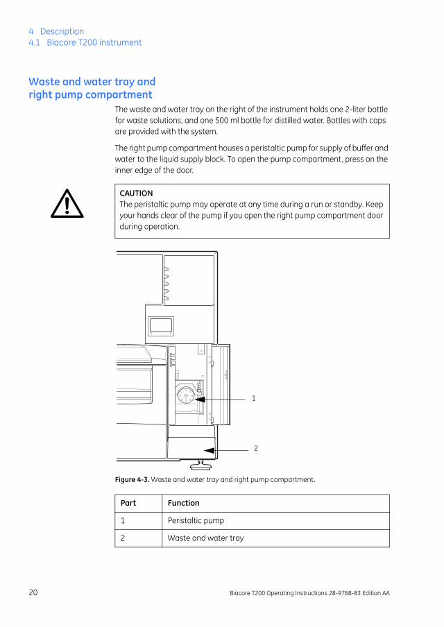
Waste and water tray and right pump compartment
The waste and water tray on the right of the instrument holds one 2-liter bottle for waste solutions, and one 500 ml bottle for distilled water. Bottles with caps are provided with the system.
The right pump compartment houses a peristaltic pump for supply of buffer and water to the liquid supply block. To open the pump compartment, press on the inner edge of the door.
Figure 4-3. Waste and water tray and right pump compartment.
CAUTIONThe peristaltic pump may operate at any time during a run or standby. Keep your hands clear of the pump if you open the right pump compartment door during operation.
Part Function
1 Peristaltic pump
2 Waste and water tray
1
2
20 Biacore T200 Operating Instructions 28-9768-83 Edition AA

Description 4
The waste tubes are fitted on the waste bottle cap. Before starting a run, make sure that the tube fittings are tightened and that the waste bottle is empty.
Sensor chip portThe cover to the sensor chip port is controlled through software commands and cannot be opened by hand. See Section 5.3 for further details.
4.2 Flow system and sample handlingThe liquid handling system comprises two syringe pumps, one peristaltic pump, the Integrated µ-Fluidic Cartridge (IFC), the autosampler with injection needle, and the liquid supply block.
The syringe pumps are used for precision delivery of samples, reagents and running buffer to the sensor chip surface via the IFC. The peristaltic pump supplies buffer and water to the liquid supply block. It also pumps waste solution from the liquid supply block to the waste bottle.
A simplified diagram of the liquid system showing delivery of samples and running buffer to the IFC is shown in Figure 4-4.
Figure 4-4. Schematic diagram of the liquid handling system, showing delivery of samples and running buffer to the IFC.
NOTICEThe waste bottle and the cap must be of the same type and size as the ones delivered with the system to avoid pressure disturbances in the liquid handling system.
Biacore T200 Operating Instructions 28-9768-83 Edition AA 21

4 Description4.2 Flow system and sample handling
Integrated µ-Fluidic Cartridge (IFC) The IFC consists of a series of micro channels and membrane valves encased in a plastic housing, and serves to control delivery of liquid to the sensor chip surface.
Sample compartment and autosampler
Sample compartment
The temperature-controlled sample compartment holds the autosampler and the sample injection unit. The rack tray port on the front of the instrument is controlled from the software.
Illumination of the sample compartment can be switched on and off through the software command Tools:Rack Illumination.
Note: Condensation may appear on the window of the sample compartment door during a temperature change. This is normal, and the condensation should evaporate when the temperature has stabilized.
Autosampler
Samples and reagents are held in a microplate and/or rack in the autosampler and are dispensed from there through the injection needle. The sample compartment is temperature-controlled.
Figure 4-5. The autosampler.
1
2 2
3
4
5
6
22 Biacore T200 Operating Instructions 28-9768-83 Edition AA

Description 4
Liquid supply block
The liquid supply block is part of the autosampler assembly. It is used for washing the needle and emptying waste solutions. The peristaltic pump maintains a continuous flow of running buffer and water to the liquid supply block throughout a run, ensuring fresh liquids at all times.
Figure 4-6. The liquid supply block. (The design may differ in older instruments but the function is the same.)
Part Function
1 Sample microplate
2 Injection needle
3 Liquid supply block
4 Reagent rack
5 Rack tray
6 Rack tray carriage
Part Function
1 Waste outlet
2 Distilled water
3 Running buffer
2
3
1
Biacore T200 Operating Instructions 28-9768-83 Edition AA 23

4 Description4.2 Flow system and sample handling
Microplates and racks
Sample microplateBiacore T200 uses standard 96-well and 384-well microplates that are mounted on the rack tray. The microplate is held in position by a spring-loaded catch.
Figure 4-7. Rack tray with 96-well microplate.
Biacore T200 is designed to accommodate both shallow and deep-well microplates conforming to the Society of Biomolecular Screening (SBS) standard. However, compatibility can only be guaranteed for microplates supplied or approved by GE Healthcare. For information about compatibility with other microplates, contact your local GE Healthcare representative.
Adhesive foilThe microplate should be covered with adhesive foil to prevent sample evaporation.
Reagent rack
The reagent rack holds reagents and other solutions. The rack slides into the holder on the rack tray and clicks into position. When changing racks, make sure that the rack is correctly mounted and that it is pushed firmly into position. (If you attempt to mount the rack in the wrong orientation, it will not click into position and you will not be able to insert the rack tray into the instrument.)
NOTICEUse only foil supplied by GE Healthcare. The adhesive substance on the foil is only present between wells. Align the foil with the microplate when attaching it to avoid clogging the needle with adhesive.
24 Biacore T200 Operating Instructions 28-9768-83 Edition AA

Description 4
Figure 4-8. Reagent rack mounted on the rack tray.
Sample and reagent rackA combined sample and reagent rack is available. The sample and reagent rack is inserted into the sample compartment instead of the rack tray.
Figure 4-9. Sample and reagent rack.
Sensor chipThe sensor chip is a gold-coated glass slide mounted on a supporting frame. The sensor chip is normally enclosed in a protective cassette. Do not remove the sensor chip from the cassette. Figure 4-10 shows the sensor chip separate from the cassette for illustration purposes.
NOTICEAlways use vials with caps as supplied by GE Healthcare. It is important that the injection needle can penetrate the vial caps properly.
Biacore T200 Operating Instructions 28-9768-83 Edition AA 25

4 Description4.3 Indicators and switches
Figure 4-10. The sensor chip and the protective cassette.
4.3 Indicators and switches
Status indicatorsThe status indicators on the front panel are described below
Part Description
1 Frame
2 Gold-coated glass slide
3 Cassette
32
1
Indicator Function
ready (green) Lit when power is on
system (red) This indicator is lit for a few seconds after the power is switched on. If the indicator lights in other circumstances, turn off the instrument and call your GE Healthcare service representative.
temperature (yellow) Lights when the temperature at the flow cells is stable at the preset temperature. Flashes when the temperature is not stable.
sensor chip (green) Lit when a sensor chip is docked and ready. Flashing when a chip is inserted but not docked.
run (green) Lit when a run is in progress.
ready
run
sensor chip
temperature
system
26 Biacore T200 Operating Instructions 28-9768-83 Edition AA

Description 4
Mains power switchThe mains power connector and switch is located on the mains input panel, at the rear right of the instrument
Figure 4-11. Mains input panel at the rear of the instrument.
4.4 Temperature controlSPR measurements are sensitive to changes in temperature. It is important that a constant temperature is maintained at the sensor chip surface throughout the run.
Analysis temperatureThe detection area housing the sensor chip is maintained at a precisely controlled temperature (range 4-45°C, max. 20°C below ambient temperature). Runs will not start if the temperature at the sensor surface is not stable. You can choose to ignore or wait for the temperature to stabilize. The Temperature lamp on the instrument front panel flashes if the analysis temperature is not stable.
Sample compartment temperatureThe sample compartment is maintained at a temperature that may be set from 4-45°C, max. 15°C below ambient temperature.
The sample compartment temperature is set independently of the analysis temperature: injected samples have sufficient time in the needle and IFC to equilibrate to the analysis temperature regardless of sample compartment temperature.
Biacore T200 Operating Instructions 28-9768-83 Edition AA 27

4 Description4.5 Control system
Condensation may occasionally drip from the instrument during long runs at low temperatures, particularly if ambient humidity is high. This is normal and does not affect instrument operation.
4.5 Control systemBiacore T200 Control Software is a complete software for control and supervision of Biacore T200.
Biacore T200 Evaluation Software is a stand-alone software for evaluation of results obtained from Biacore T200. The software is normally installed on the same computer as the Biacore T200 Control Software, although connection to the instrument is not required for using Biacore T200 Evaluation Software.
NOTICEThe system does not wait for the sample compartment temperature to stabilize. The Temperature lamp and screen display show the analysis temperature, not the sample compartment temperature.
28 Biacore T200 Operating Instructions 28-9768-83 Edition AA

Operation 5
5 Operation
This chapter guides you through the basic operation of Biacore T200.
5.1 Starting the system1 Switch on the instrument. The status lamps on the front panel light in the
following sequence:
a) All the lamps light for a few seconds and then go out.
b) The green Ready lamp lights.
c) The yellow Temperature lamp flashes to indicate non-stabilized temperature, and then is steadily lit when the temperature at the detection unit is stable. The time required for temperature stabilization depends on the set temperature and ambient temperature. The instrument uses the last analysis and sample compartment temperatures set before shutdown as default. Temperature stabilization should not take more than an hour.
2 Switch on the printer and the PC.
3 Start Biacore T200 Control Software from the Windows start menu. The shortcut is installed in the Biacore group.
4 The software establishes connection with the instrument, which takes about 30 seconds.
5.2 Preparing the system for a run
Preparing buffers
Using standard buffers
Always keep a high standard of hygiene in the solutions used. Prepare fresh buffer before each run. Standard buffers are available from GE Healthcare as stock solutions1. To prepare running buffer, dilute the stock solution with distilled and filtered water.
1 Buffers in 200 ml ready-to-use packs are not recommended for use with Biacore T200.
Biacore T200 Operating Instructions 28-9768-83 Edition AA 29

5 Operation5.2 Preparing the system for a run
Preparing your own buffers
All buffers used in Biacore T200, both as running buffer and for sample and reagent preparation, should be filtered through a 0.22 µm filter.
Including a surfactant in the buffer can reduce non-specific adsorption of proteins to the autosampler tube and the IFC channels. Surfactant P20 is available from GE Healthcare. You may omit surfactant if your sample is detergent-sensitive. However, you may then want to clean the flow system more frequently (see Chapter 6 for more information).
Setting up the liquid system1 Open the right pump compartment door and check that the clamp of the
peristaltic pump is properly fastened: the lever should be in a vertical position.
2 Fill a suitable bottle with running buffer. Make sure that the bottle is clean before use. Fit a cap with gasket on to the bottle and place it on the buffer tray. Insert the tube marked A through the cap, into the running buffer bottle.
3 If you plan to use different buffers, fill up to three additional bottles with the required buffers. Fit caps with gaskets on to the bottles and place them on the buffer tray. Insert the tubes marked B, C and D into the bottles.
NOTICEAlways use freshly prepared buffer solution. Replace the buffer after every run or at least every 48 hours.
30 Biacore T200 Operating Instructions 28-9768-83 Edition AA

Operation 5
Figure 5-1. Bottles on the buffer tray.
4 Place unused buffer tubing in the holder inside the pump compartment door.
5 Place a 2-liter bottle for waste solution on the waste and water tray. Fit the cap carrying the waste tubes on to the bottle. Tighten the tube fittings by hand. Do not use a smaller bottle for waste.
6 Fill a 500 ml bottle with distilled and filtered water. Fit a cap with gasket and place it on the waste and water tray. Insert the water tube into the water bottle.
NOTICEAlways use fresh water. Replace before each run, or at least every 48 hours. Do not run the system without water.
Biacore T200 Operating Instructions 28-9768-83 Edition AA 31

5 Operation5.3 Basic operating procedures
Figure 5-2. Bottles on the waste and water tray.
5.3 Basic operating procedures
Inserting the sensor chipBefore Biacore T200 can be used, a sensor chip must be docked in the instrument.
1 Click on the toolbar icon or choose Insert Chip from the Tools menu.
2 If a sensor chip is already docked, click on the Eject icon that is shown instead, or choose the Eject Chip from the Tools menu.
Click Eject Chip in the dialog box that appears. This will empty the flow cells and eject the sensor chip.
3 The sensor chip port opens automatically when the chip is undocked.
4 If you are using a new chip, choose New Chip. Select the chip type from the list, a Chip id and an optional lot number. The Chip id must be unique among the chips that have been used on the instrument. Including the date in the Chip id helps to ensure a unique value.
32 Biacore T200 Operating Instructions 28-9768-83 Edition AA

Operation 5
If you are re-using a chip that has previously been docked in the instrument, choose Reuse chip and select the Chip id from the list. A chip that has been previously used in a different instrument will not be included in the list and must be inserted as a new chip.
5 Insert the sensor chip and close the port cover:
Figure 5-3. Inserting the sensor chip:A. Insert the sensor chip into the sensor chip port, with the arrows pointing into the instrument.B. Make sure that the sensor chip is fully inserted.C. Close the sensor chip port cover. Press gently until it clicks into position.
A B
C
Biacore T200 Operating Instructions 28-9768-83 Edition AA 33

5 Operation5.3 Basic operating procedures
6 If you need to open the sensor chip port cover at this stage (for example if you have inserted the wrong chip), click Cancel. This will close the Insert Chip dialog without docking the chip—you can then choose Insert Chip again to open the port cover.
7 Click Dock chip. A standby flow of running buffer is started automatically when the docking procedure is completed.
Initiating the liquid handling systemIf buffer solutions are changed, check the Prime before run option in the System Preparations dialog, which appears during setup of each run. If you want to prime the system at any other time, choose Tools:Prime to ensure that all parts of the liquid handling system are flushed with fresh buffer. This procedure takes 6-7 minutes.
Setting the temperatureThe temperature at the flow cell is shown in the status window of the Biacore T200 screen. To change the analysis and/or sample compartment temperature:
Choose Tools:Set Temperature and enter the required temperature values.
You can start a run before the temperature has stabilized. However, the run will be paused before a step where analysis temperature is critical. A message is displayed and the instrument enters standby, until temperature has stabilized. You can choose to ignore this message, but this is not recommended as the signal is not stable.
34 Biacore T200 Operating Instructions 28-9768-83 Edition AA

Operation 5
5.4 Preparing samples and reagents
Ejecting the rack trayThe removable rack tray carries one microplate and one reagent rack, and is mounted on the rack tray carriage in the sample compartment. The combined sample and reagent rack is mounted directly on the rack tray carriage.
The rack tray (or the sample and reagent rack) can be ejected in three situations:
• before a run, when preparing samples and reagents,
• during the setup of a run,
• during a manual run.
Ejecting the rack tray before a run
Click on the toolbar button or choose Tools:Eject Rack to eject the rack tray carriage, in order to access the rack tray. The rack tray is ejected and the following dialog box displayed:
Figure 5-4. Eject Rack Tray dialog.
When you click on OK in the Eject Rack Tray dialog, the rack tray is moved into the instrument immediately.
CAUTIONThe rack tray automatically moves into the instrument a preset time after it has been ejected. The time is set in Tools:Preferences. A timer in the dialog indicates when the rack tray will be automatically moved into the instrument.
Biacore T200 Operating Instructions 28-9768-83 Edition AA 35

5 Operation5.4 Preparing samples and reagents
Removing the rack tray or sample and reagent rack
Press the catch under the front edge of the rack tray to release the tray. Lift the rack tray slightly and take it out of the instrument.
Preparing samples1 When you dispense the samples into the sample microplate or sample and
reagent rack, check that all samples are at the bottom of the wells. It is easy to trap air bubbles at the bottom of the wells in 384-well microplates: make sure all such air bubbles are removed.
2 Cover the used sample wells with recommended adhesive foil, available from GE Healthcare. This prevents evaporation from the samples during analysis.
3 Open the catch on the rack tray and slide the microplate onto the rack tray. Place the microplate with well A1 facing towards the front of the rack tray.
0
Figure 5-5. Removing the rack tray from the instrument.A. Release the rack tray (press the catch under the tray).B. Lift out the rack tray.
A B
NOTICEMake sure that you install the microplate with well A1 facing the front of the microplate. Otherwise the sample order will be incorrect.
36 Biacore T200 Operating Instructions 28-9768-83 Edition AA

Operation 5
Figure 5-6. Placing the sample microplate on the rack tray.
4 Close the catch and make sure that the microplate is properly seated on the rack tray.
Figure 5-7. Fastening the sample microplate on the rack tray.
Adjusting the rack tray
To accommodate some brands of microplates, it may be necessary to adjust the retainers on the rack tray. Contact your GE Healthcare representative for more information. Adjust the retainers as follows:
1 Loosen the screws underneath the rack tray and turn the retainers through 90º to accommodate the microplate.
2 Tighten the screws again after the adjustment.
A1
Biacore T200 Operating Instructions 28-9768-83 Edition AA 37

5 Operation5.4 Preparing samples and reagents
Figure 5-8. Adjusting the rack tray.
Changing reagent racks1 Remove the rack from the rack tray by pushing firmly on the rack
Figure 5-9. Removing the rack from the rack tray.
2 Slide the new rack into the holder on the rack tray. Make sure that it is correctly oriented. The rack can only be fully inserted in one orientation.
Figure 5-10. Fitting the rack on the rack tray.
3 Push the rack until it snaps into position on the rack tray. Make sure that the rack is properly in place.
38 Biacore T200 Operating Instructions 28-9768-83 Edition AA

Operation 5
Preparing reagents1 Open the cover of the reagent rack, or the sample and reagent rack.
2 Cap the vials and place in the reagent rack. Use only caps supplied for use in Biacore T200 by GE Healthcare.
Figure 5-11. Reagent rack with cover open.
3 Close the reagent rack cover and press until it snaps shut. Make sure that the cover is completely closed
Figure 5-12. Reagent rack with cover closed.
Installing the rack tray or sample and reagent rack
1 If the rack tray port is not open when you are ready to install the rack tray, eject the rack tray carriage.
2 Insert the rack tray. Press gently until the rack tray snaps into place.
3 The rack tray automatically moves into the instrument a preset time after it has been ejected. The time is set in Tools:Preferences. Click on OK in the Eject Rack Tray dialog to move the rack tray into the instrument immediately.
Biacore T200 Operating Instructions 28-9768-83 Edition AA 39

5 Operation5.5 Starting the run
Figure 5-13. Loading the rack tray into the sample compartment.
5.5 Starting the runWhen docking of the sensor chip is ready, a standby flow of running buffer is started.
• To start a wizard run, choose Run:Wizard. Choose the type of run and select a template. Follow the step-by-step instructions of the wizard.
• To start a method run, choose Run:Method. Open a method or build a new method.
• Before you start a manual run, run Tools:Prime and Tools:Normalize. To start a manual run, choose Run:Manual run. Define the flow path and click Start .
For details of the different types of run, refer to Biacore T200 Software Handbook.
5.6 Finishing the run
Standby modeWhen a run is completed, the instrument is automatically placed in standby mode: a continuous low flow of buffer (using buffer tube A) is maintained through the flow system to prevent accumulation of buffer residues.
The default standby period is 7 days. Liquid consumption during standby is approximately 65 ml/24 hours.
40 Biacore T200 Operating Instructions 28-9768-83 Edition AA

Operation 5
Wash buffer tubingUse the maintenance tool Wash Buffer Tubing when you change from buffers containing substances that tend to adsorb to the tubing, e.g. detergent or serum albumin.
If you have used buffer tubes B, C or D and do not plan to use them in coming runs, run the maintenance tool Empty Buffer Tubing to wash and empty the buffer tubing, then place unused tubes in the holder in the left pump compartment.
For details of buffer tubing maintenance, see Chapter 6.
ShutdownIf you want to shut down the instrument completely, see Section 6.5 for instructions.
NOTICEAs a general recommendation use distilled and filtered water for standby to minimize salt deposits. However, if an immobilized sensor chip is docked and should be used later, buffer may be used to protect the ligand on the sensor surface.
Biacore T200 Operating Instructions 28-9768-83 Edition AA 41

5 Operation5.6 Finishing the run
42 Biacore T200 Operating Instructions 28-9768-83 Edition AA

Maintenance 6
6 Maintenance
This chapter summarizes user maintenance procedures. If more extensive service is required, please contact your GE Healthcare service representative.
Several maintenance operations are performed using software tools with on-screen instructions in English. See Appendix A for these instructions in your local language.
6.1 GeneralMake sure that the BIAmaintenance Kit is available before starting maintenance procedures.
Regular maintenance of Biacore T200 is essential for reliable results. It is important to keep the instrument free from contamination such as microbial growth and adsorbed proteins in the liquid handling system.
Regular checks and maintenance should be done according to the schedules below. You will be reminded of the need for Desorb and Desorb and Sanitize procedures via a maintenance scheduler in the Control Software. Do not ignore maintenance reminders.
WARNINGIf the instrument is contaminated with biohazards, contact your local Service representative for further information about decontamination procedures.
WARNING BIAdisinfectant solution is corrosive. The solution should be diluted shortly before use as described in the Instructions for Use provided with the kit.
NOTICESome maintenance procedures will destroy the ligand on a prepared sensor chip. Always use the separate Sensor Chip Maintenance that is included in the maintenance kit unless otherwise stated.
NOTICEDo not use BIAdesorb solution 1 at analysis temperatures below 20 ºC. BIAdesorb solution 1 precipitates at low temperatures.
Biacore T200 Operating Instructions 28-9768-83 Edition AA 43

6 Maintenance6.2 Maintenance summary
6.2 Maintenance summaryRegular checks and maintenance should be done according to the schedule below.
User maintenance operationsTable 6-1. Schedule for user maintenance operations.
User service operations Table 6-2. Tools for user service operations.
Interval Action
Daily/after each run Empty the waste bottle
Weekly Inspect tube fittings and pumps, check for leaks
Clean the flow system (Desorb)
Monthly Clean the instrument cover
Clean and disinfect the flow system (Desorb and Sanitize)
Inspect the needle and the liquid supply block
Inspect the sample compartment, look for signs of flooding
Run System Check
Tool Description
System Check Always run System Check before calling GE Healthcare Service. The results of the System Check may help in diagnosing and solving your problems.
Software Problem Report
Run this tool if you experience problems with Biacore T200 Software which do not have a readily apparent solution.
Flow System Wash This tool will flush the flow system with buffer at a high flow rate to clear obstructions such as aggregated particles.
Superclean This tool can be used for extensive cleaning if the Desorb and Sanitize procedure is not sufficient to clean the flow system.
44 Biacore T200 Operating Instructions 28-9768-83 Edition AA

Maintenance 6
6.3 User maintenance operations
Materials required
Kit contentsTable 0-1. Contents of Biacore Maintenance Kit , type 2.
StorageAll solutions except BIAdesorb solution 1 should be stored at +4-8°C. BIAdesorb solution 1 should be stored at room temperature.
In addition to the maintenance kit you will need the following materials:
• Distilled and filtered water
• 70% (v/v) ethanol
• Clean, lint-free cloths
• Series S Sensor Chip CM5
Cleaning the instrumentIf necessary, clean the cover of the processing unit with a moist cloth. Use water or a mild detergent.
The buffer tray and the waste and water tray can be removed for cleaning.
If necessary, clean the waste bottle cap as follows:
1 Unscrew the cap from the waste bottle.
Solution/Item Specification
BIAdesorb solution 1 0.5% (w/v) sodium dodecyl sulfate (SDS), two bottles of 95 ml
BIAdesorb solution 2 50 mM glycine pH 9.5, two bottles of 95 ml
Notes: BIAtest solution 14.9% sucrose in HBS-N buffer with 3 mM EDTA, one bottle of 65 ml
BIAdisinfectant solution (conc.) Sodium hypochlorite with 8-12% active chlorine, three bottles of 10 ml
BIAnormalizing solution 70% (w/w) glycerol, one bottle of 90 ml
HBS-N buffer 10X One bottle of 50 ml
Sensor Chip Maintenance One sensor chip
Biacore T200 Operating Instructions 28-9768-83 Edition AA 45

6 Maintenance6.3 User maintenance operations
2 Loosen the tube fittings and remove the tubes from the cap.
3 Rinse the cap in deionized water.
4 Attach the tubes to the cap and tighten the fittings firmly.
Checking for leaksOnce a week, check that there are no liquid or salt deposits at the following positions:
• Syringe pump: tube fittings, inside the pump barrel, at the plunger drive (for details, see Figure 6-1)
• Buffer selector valve: tube fittings
• Degasser: tube fittings
• Peristaltic pump: tube fittings below the pump
If you find leaks at tube fittings, clean with water and tighten the connections.
If you find leaks in either of the syringe pumps, call your GE Healthcare Service representative.
1
2
3
4
46 Biacore T200 Operating Instructions 28-9768-83 Edition AA

Maintenance 6
Figure 6-1. Leakage check points.
Cooling unitCondensate water may collect on the drip tray underneath the instrument during long runs with cooling below ambient temperature. This is normal and does not indicate leakage.
Part Function
1 Degasser
2 Syringe pumps (see items 5–8)
3 Buffer selector valve
4 Peristaltic pump connections
5 Tubing connections
6 Plunger tip
7 Pump barrel
8 Plunger drive
5
6
7
8
Biacore T200 Operating Instructions 28-9768-83 Edition AA 47

6 Maintenance6.3 User maintenance operations
Cleaning and disinfecting the flow systemTools for cleaning and disinfecting the flow system are available under Maintenance Tools in the More Tools menu:
DesorbRun the maintenance tool Desorb to clean the sample tubing and IFC channels at least once a week, or more often if proteins and other substances used show a tendency to adsorb to the walls of the flow system (often revealed by carry-over problems in assays).
Desorb and SanitizeTo prevent microbial growth in the instrument, keep a high standard of hygiene in the solutions used.
Run the maintenance tool Desorb and Sanitize at least once a month, to remove adsorbed material and disinfect the system. All buffer tubing is washed, and buffer tubes B, C and D are emptied during the procedure.
Empty Buffer Tubing
The maintenance tool Empty Buffer Tubing washes and empties all buffer tubing. Run this tool when you have used buffer tubes B, C or D, and do not intend to use them any more.
Wash Buffer Tubing Run this tool when you change from buffers containing substances that tend to adsorb to the tubing, e.g. detergent or serum albumin.
You may choose whether to wash one or all of the buffer tubes are washed during the procedure. The selection is made at the start of the procedure.
48 Biacore T200 Operating Instructions 28-9768-83 Edition AA

Maintenance 6
Normalizing the detectorThis procedure adjusts the detector response to compensate for slight differences in individual sensor chips. For best performance, run this procedure once for each new chip. The procedure can either be run before immobilization or before the first run using the immobilized chip. Normalization injects BIAnormalizing solution (70% glycerol in water) over the chip surface.
At the start of a runCheck the Normalize detector option in the System Preparations dialog, which appears before the start of each run.
At any other timeRun Maintenance Tools:Normalize to normalize the detector response for all flow cells, when changing sensor chip.
NOTICERun Normalize with the sensor chip that will be used for the run. Do not use Sensor Chip Maintenance for this purpose.
Biacore T200 Operating Instructions 28-9768-83 Edition AA 49

6 Maintenance6.4 User service operations
6.4 User service operationsTools for user service operations are available under Test Tools and Service Tools in the More Tools menu:
System checkThis procedure performs a comprehensive check of system performance, using a standard sucrose solution (BIAtest solution), which is provided in the Biacore Maintenance Kit .
Use a new Sensor Chip CM5 for this procedure.
System check resultsTable 6-3. System check diagnostics.
Test Likely cause of failure Explanation/Action
Reagent pumpWater
Buffer
Air in injections 1 and 2 The clamp on the upper peristaltic pump was not fastened.
Air in single injection Tubing squeezed or not fully inserted into buffer or water.
Blank injection deviates from baseline
Deposits in the liquid supply block.
Merged Injections Fc1
Fc2
Fc3
Fc4
Leaks in syringe pump or other parts of flow system
Call GE Healthcare Service.
Flow cell leakage too large
Bad IFC. Call GE Healthcare Service.
50 Biacore T200 Operating Instructions 28-9768-83 Edition AA

Maintenance 6
SupercleanRun the maintenance tool Desorb and Sanitize followed by Superclean if you suspect that the Desorb and Sanitize procedure is not sufficient to clean the flow system. Total run time is about 1.5 hours.
Test Likely cause of failure Explanation/Action
MixingMix1
Mix2
Difference
Leaks in syringe pump or other parts of flow system
Call GE Healthcare Service.
Salt deposits on the needle
Clean the needle .
Check that vials are clean and unused.
RefractometerFc1
Fc2
Fc3
Fc4
Too low values A new chip was not used. May also result in too large spread in baseline level.
Too high or too low values
Wrong buffer.
Injections Fc1
Fc2
Fc3
Fc4
Leaks in syringe pump or other parts of flow system
Call GE Healthcare Service.
Flow cell leakage too large
Bad IFC. Call GE Healthcare Service.
Noise Drifting baseline A new chip was not used.
Temperature not stable. Call GE Healthcare Service.
Buffer selectorBuffer A
Buffer B
Buffer C
Buffer D
Tubing in wrong bottles Check that the buffer tubes are inserted in the correct bottles.
Buffer selector not working
Call GE Healthcare Service.
Leaking syringe pump Call GE Healthcare Service.
Biacore T200 Operating Instructions 28-9768-83 Edition AA 51

6 Maintenance6.4 User service operations
Opening the sample compartmentIf you need to access the needle and the liquid supply block for cleaning:
1 Choose Tools:Stop Standby if the instrument is in Standby mode.
2 Remove any microplate and reagent rack from the sample compartment. Make sure that the rack tray is fully retracted and the sample compartment is closed.
3 Turn off the MAINS POWER switch at the rear right of the instrument.
4 Open the sample compartment door: use a flat head screwdriver to turn the lock screw 1/8 turn counter-clockwise.
Figure 6-2. Opening the sample compartment door.
CAUTIONThe sample compartment door swings upwards when released. Do not lean over the instrument when you open the sample compartment door.
52 Biacore T200 Operating Instructions 28-9768-83 Edition AA

Maintenance 6
Cleaning the sample compartment
1 Lift off the insulation plate at the back of the sample compartment.
Figure 6-3. The sample compartment door opened.
2 Remove spillage from the sample compartment with water or ethanol as required.
3 Dry with a lint-free cloth.
4 If salt residues have accumulated on the needle or liquid supply block, remove them with a damp cloth.
5 Replace the insulation plate at the back of the sample compartment.
6 Pull down the sample compartment door, and close the door by pressing it down until it snaps into position.
7 Start the instrument and the software.
8 Run Tools:Prime to wash the needle and the liquid supply block.
Removing the sample compartment box If required, the sample compartment box can be removed for better access to the sample compartment.
To remove the sample compartment box:
1 Open the sample compartment.
2 Pull out the tubing from the water bottle and remove the bottle.
WARNING! The injection needle is sharp and may penetrate protective gloves. Take particular care if hazardous agents have been used.
Insulation plate
Biacore T200 Operating Instructions 28-9768-83 Edition AA 53

6 Maintenance6.5 Shutting down the system
3 Remove the cap from the waste bottle and remove the bottle.
4 Pull out the tubing from the buffer bottles and remove the bottles. Place the tubing ends in the holder inside the left pump compartment.
5 Remove the buffer tray and the waste and water tray.
6 Use two 2.5 mm screwdrivers to press the two catches inside the sample compartment box (see Figure 6-4). Pull the box out of the instrument.
Figure 6-4. Opening the sample compartment box.
Replacing the sample compartment box1 Push the sample compartment box along two guide rails into the
instrument. Press until it locks into position.
2 Replace the buffer tray and the waste and water tray.
3 Pull down the sample compartment door, and close the door by pressing it down until it snaps into position.
4 Make sure that no tubing is in the way, then close the door by pressing it onto the sample compartment box.
6.5 Shutting down the systemBiacore T200 should normally be left in standby mode when not in use. The instrument maintains a low flow of liquid through the flow system. The maximum unattended standby period is 7 days.
If the instrument is not to be used for a period of about two weeks or more, run the Shutdown procedure to shut the instrument down completely.
54 Biacore T200 Operating Instructions 28-9768-83 Edition AA

Maintenance 6
StandbyThe instrument enters standby mode automatically at the end of a run. To put the instrument in standby mode manualy, choose Tools:Standby.
Before leaving the instrument unattended in standby mode, check
• That there is sufficient water or buffer for the standby period, and that the buffer tube marked A is fully inserted into the water bottle.. Liquid consumption during standby is approximately 65 ml/24 h.
• That the waste bottle is emptied.
ShutdownTo shut down the instrument completely:
1 Run Desorb and Sanitize to clean the flow system.
2 Eject the rack tray carriage and remove the rack tray.
3 Prepare a bottle of distilled and filtered water, and a bottle of 70% ethanol. Choose Shutdown from the Tools menu. Follow the instructions on the screen.
The procedure flushes the flow system and then empties the IFC of liquid. Total run time is about 20 minutes.
4 When instructed, open the right door and open the tube clamp of the peristaltic pump to relieve the pressure on the pump tubing (see Figure 6-5).
5 Exit from Biacore T200 Control Software by selecting File:Exit . Select Exit the software.
6 Open the sample compartment door and clean the needle and liquid supply block if necessary.
7 Remove bottles, the waste cap assembly and the bottle trays. Seal the loose tubing ends, for instance by wrapping them in plastic bags.
NOTICEDistilled and filtered water is generally recommended instead of buffer for standby, to minimize salt deposits. However, if an immobilized sensor chip is docked and should be used later, buffer may be necessary to preserve the sensor surface during standby.
Biacore T200 Operating Instructions 28-9768-83 Edition AA 55

6 Maintenance6.5 Shutting down the system
Figure 6-5. Opening the tube clamp. To completely open the clamp, flip the lever to the right, until it touches the compartment wall.
Storage conditionsFor storage, first perform the Shutdown procedure to empty and dry the flow system, then clean the outside surfaces of the instrument using a soft cloth and water or a mild detergent. Release the peristaltic pump clamp (see above) before storage.
Maintain normal conditions of temperature and humidity while the system is in storage:
• Temperature: preferably room temperature, not below freezing
• Relative humidity: non-condensing, preferably low humidity
Contact GE Healthcare if you are uncertain of storage conditions.
NOTICEBefore re-starting the system, make sure that the tube clamp is properly fastened.
56 Biacore T200 Operating Instructions 28-9768-83 Edition AA

Troubleshooting 7
7 Troubleshooting
This chapter gives a brief guide to troubleshooting procedures for problems with Biacore T200.
7.1 System-related problems
Instrument hygieneA fundamental requirement for trouble-free operation of Biacore T200 is that the system is kept clean and is maintained regularly according to the following guidelines:
• Always use fresh buffer and distilled water. If you prepare your own buffers, filter buffer and water through a 0.22 µm filter to remove particles. Ready-to-use buffers from GE Healthcare are filtered.
• Follow the recommended maintenance procedures as described in Chapter 6. Do not ignore maintenance schedule reminders.
• If the system is used with particularly “sticky” molecules or complex mixtures such as serum, clean the flow system thoroughly after each run.
• Leave the system in standby mode with freshly filtered distilled water or buffer when not in use, or run the Shutdown procedure to empty the flow system. Do not leave the instrument with liquid standing still in the flow system.
• Do not take the sensor chip out of its protective cassette. Dust or other particles on the sensor chip surface can seriously interfere with detection.
Instrument considerations• If the PC does not seem to communicate with the instrument, check that
the communication cable is properly connected.
• Make sure there is adequate ventilation around at the instrument site.
• Check the accessible tube fittings on the pumps, buffer selector valve and degasser regularly for leaks.
• Make sure the clamp on the peristaltic pump is properly closed at the start of a run. If the clamp is not closed, buffer and water will not be supplied properly to the liquid supply block.
Biacore T200 Operating Instructions 28-9768-83 Edition AA 57

7 Troubleshooting7.1 System-related problems
Buffer considerations• Make sure that the correct buffer tubing is inserted into the buffer bottle(s).
If you are only using one buffer, you should use buffer tubing A. The syringe pumps will be empty and the response will be out of range if no buffer is supplied to the flow cell.
• Check that there is sufficient buffer in the buffer bottle(s) and water in the water bottle at the start of a run.
Sample considerations• Make sure that you have sufficient sample and reagent in the vials and
microplate. The volumes specified in the software (See the Biacore T200 Software Handbook) are minimum volumes with due consideration for dead volumes in different vials and microplates. Larger volumes may be needed if you have problems with injection of air in sample or reagent injections.
• Use only recommended vials and microplates. Always cap vials and cover microplates with foil, using the products supplied for this purpose by GE Healthcare.
• Use only recommended caps for vials and adhesive foil for microplates. Sample evaporation from uncovered samples will both affect the sample concentration and reduce the volume, possibly resulting in injection of air. Use of unsuitable adhesive foil may block the autosampler needle with adhesive.
For further helpIf you are experiencing instrument-related problems and are unable to identify and/or correct them, run System Check, then contact your GE Healthcare Service representative.
58 Biacore T200 Operating Instructions 28-9768-83 Edition AA

Troubleshooting 7
7.2 Assay-related problems
Ligand considerationsLoss of ligand activity on the surface of the sensor chip is a common source of application problems.
• If you cannot immobilize sufficient ligand with retained analyte-binding capacity, try alternative immobilization methods or use a capturing approach. In some cases it may be sufficient to perform immobilization at a milder pH, or to avoid exposure of the ligand to immobilization buffer as far as possible. The immobilization wizard supports dilution of ligand into immobilization buffer immediately before injection, for ligands that do not withstand extended exposure to immobilization conditions.
• Make sure that the ligand withstands regeneration conditions without loss of activity. If you cannot find suitable regeneration conditions, consider using a capturing approach so that you use fresh ligand on the surface for each analysis cycle.
• If you plan to store sensor chips with immobilized ligand for later use, perform control experiments to establish that the ligand retains activity in the storage conditions.
• Make sure you choose the correct flow path for a run. If you inject samples over a flow cell where no ligand is immobilized, you will not see significant binding.
Sample considerations• Make sure the samples do not precipitate at the concentrations and buffer
conditions used. Even micro-precipitation on the surface can seriously disturb the detection (or in the worst case block the flow system), and is generally seen as excessive noise and irregularities in the sensorgrams.
• Where possible, samples should be prepared in running buffer or similar conditions. Drastic changes in buffer composition between running buffer and sample can introduce artefacts that may be difficult to interpret.
For further helpSeveral Biacore publications provide guidance on design and execution of experiments. Contact GE Healthcare for more information.
Biacore T200 Operating Instructions 28-9768-83 Edition AA 59

7 Troubleshooting7.2 Assay-related problems
60 Biacore T200 Operating Instructions 28-9768-83 Edition AA

Reference information 8
8 Reference information
8.1 Specifications
General
Processing unit
Automation 48 h unattended operation
Limit of detection Typically below 1 RU (approximately 1 pg/mm2 for proteins on Sensor Chip CM5)
Sample volume 10-425 µl (application dependent)
Sample/reagent capacity One 384 well or one 96 well microplate + 33 reagent vials, or 78 vials for samples and reagents
Analysis time per sample Typically 2-15 min
Dimensions (see also Figure 3-1)W×D×H 600×615×690 mm
Net weight 60 kg
Weight incl. packing 80 kg
Mains requirements Autorange 100–240 V~, 50/60 Hz, protective earthing
Fuses 2×T4.0AH
Power consumption Max. 4.0 A
Ambient temperature range 18-33°C
Ambient humidity ≤85 %RH
Analysis temperature 4-45°C, max. 20°C below ambient temperature
Biacore T200 Operating Instructions 28-9768-83 Edition AA 61

8 Reference information8.1 Specifications
Flow cells
System controller and software
Reagent racksTable 8-1. Reagent rack specifications
Number of flow cells 4
Flow cell height Approximately 0.04 mm
Flow cell volume approximately 0.06 µl
PC operating system MicrosoftTM WindowsTM XP (Professional), Vista or Windows 7
Interfacing Possibilities for import of sample data and export of results, e.g. to LIMS
Reagent rack, type 120 vials, diam. 11 mm (1.5 ml Eppendorf)
Reagent rack, type 29 vials, diam. 16 mm (4.0 ml)
24 vials, diam. 7.5 mm (0.8 ml)
Sample and reagent rack9 vials, diam. 16 mm (4.0 ml)
24 vials, diam. 11 mm (1.5 ml Eppendorf)
45 vials, diam. 7.5 mm (0.8 ml)
62 Biacore T200 Operating Instructions 28-9768-83 Edition AA

Reference information 8
Microplates
Liquid containers
Buffer tray
Waste and water tray
8.2 Chemical resistanceThis section gives some general guidelines concerning chemical resistance for Biacore T200 components. Regarding exposure to solutions not covered by these guidelines, contact your GE Healthcare representative for recommendations.
The flow system and sensor chip are the only parts of Biacore T200 that come into contact with solutions. The guidelines in this section relate to tubing and connectors, selector valves, connector block, IFC and sensor chip. In most analysis situations, the ligand attached to the sensor surface limits the chemical resistance of the system as a whole.
In general, the flow system components withstand long-term exposure to common aqueous buffer solutions used in biochemical laboratories. Table 8-2 below lists compatibility with other common substances.
Concentrated organic solvents as well as long-term exposure to extremes of pH (<3 and >11) should be avoided. For solutions with short-term compatibility, do not use as running buffer or for injections longer than 10 minutes. Solutions classed as long-term compatible may be used as running buffer.
Microplate formats 96 or 384 shallow or deep-well plates, conforming to SBS standard
Running buffer 1 × 1 l , 3 × 250 ml, screw caps with gasket
Waste 2 l (must be of the same type as the one delivered with the system). Special screw cap with two tube fittings.
Water 500 ml, screw cap with gasket
Biacore T200 Operating Instructions 28-9768-83 Edition AA 63

8 Reference information8.3 Literature
Table 8-2. Chemical resistance.
8.3 LiteratureFor further information, see the Biacore T200 Handbook and the integrated software support.
8.4 Ordering informationFor ordering information visit www.gelifesciences.com/biacore.
Solution Concentration Compatibility
Acetonitrile 50% Short term
Dimethyl formamide (DMF)
50% Short-term
Dimethyl sulfoxide(DMSO)
50%10%
Short-termLong-term
Ethanol 70%10%
Short-termLong-term
Ethylene glycol 100% Short-term
Formic acid 70% Short-term
Formamide 40% Long-term
64 Biacore T200 Operating Instructions 28-9768-83 Edition AA

Maintenance and service tools Appendix A
Appendix A Maintenance and service tools
The on-screen instructions in the maintenance and service software tools are given in English. Translations to other local languages are provided in the local language versions of these Operating Instructions.
Biacore T200 Operating Instructions 28-9768-83 Edition AA 65

Appendix A Maintenance and service tools
66 Biacore T200 Operating Instructions 28-9768-83 Edition AA


28-9768-83 AA 04/2010
For contact information for your local office,please visitwww.gelifesciences.com/contact
GE Healthcare Bio-Sciences ABBjörkgatan 30751 84 UppsalaSweden
www.gelifesciences.com/biacore
GE, imagination at work and GE monogram are trademarks of General Electric Company.
Biacore is a trademark of GE Healthcare companies.
All third party trademarks are the property of their respective owners.
© 2010 General Electric Company—All rights reserved.First published April 2010
All goods and services are sold subject to the terms and conditions of sale of the company within GE Healthcare which supplies them. A copy of these terms and conditions is available on request. Contact your local GE Healthcare representative for the most current information.
GE Healthcare UK LtdAmersham Place, Little Chalfont, Buckinghamshire, HP7 9NA, UK
GE Healthcare Bio-Sciences Corp800 Centennial Avenue, P.O. Box 1327, Piscataway, NJ 08855-1327, USA
GE Healthcare Europe GmbHMunzinger Strasse 5, D-79111 Freiburg, Germany
GE Healthcare Bio-Sciences KKSanken Bldg. 3-25-1, Hyakunincho, Shinjuku-ku, Tokyo 169-0073, Japan