t5 pci-epp conversion field upgrade procedures … · 3 t5 pci-epp conversion procedures...
TRANSCRIPT

T5 PCI-EPP ConvErsIonFIEld UPgradE ProCEdUrEs(ModEls rl/FT5000/rl/rT2000)
TDN 07103-00178 Rev B Sept 15, 2009
CorPoraTE HEadqUarTErs:21405 B Street
Long Beach, MS 39560Phone: (228) 575-3188Fax: (228) 575-3200
COPYRIGHT NOTICE© 2008 Triton. All Rights Reserved. TRITON logo is a registered trademark of Triton Systems of Delaware.
2
T5 PCI-EPP ConvErsIon ProCEdUrEs
ConTEnTs
InTrodUCTIon .......................................................................................................................3ovErvIEw .............................................................................................................................4rl/FT5000 ConvErsIon ProCEdUrEs ................................................................................5rl2000 ConvErsIon ProCEdUrEs ....................................................................................10 8” Display ..................................................................................................................................................11 5.7” Display ........................................................................................................................................13
rT2000 ConvErsIon ProCEdUrEs ....................................................................................16BaTTEry rEPlaCEMEnT ProCEdUrEs .................................................................................20 Replacing the BatteRy ........................................................................................................................21
aPPEndIx a ...................................................................................................................... a-1 UpDating teRminal softwaRe pRoceDURes ....................................................................................... a-2 loaDing the mUltitech moDem configURation file (X2 Units) .................................................... a-3 save JoURnal RecoRDs ...................................................................................................................... a-4 save / RestoRe teRminal paRameteRs Using eXteRnal stoRage Device .......................................... a-6 cleaR seRial # eRRoR ....................................................................................................................... a-8 impoRtant DiffeRences with the t5 pci-epp KeypaD ..................................................................... a-9 t5 pci-epp Key management pRoceDURes ......................................................................a-10 to a-12 checK opeRation of pRinteR/pResenteR ......................................................................................... a-13 optional scReens / scReen BUttons ............................................................................................... a-14

3
T5 PCI-EPP ConvErsIon ProCEdUrEs
InTrodUCTIonThis guide covers the steps for converting X-Scale/X2 terminals shipped with VISA® Encrypting PIN Pads (VEPP) to a T5 PCI-certified EPP. These procedures include a list of tools, hardware, and software required for the conversion.
sCoPE
These procedures apply to all Triton certified service personnel involved in the process of maintaining or converting Triton ATMs.
** IMPORTANT **BEFORE ProCEEdIng wITH THE kIT HardwarE InsTallaTIon, THE TERMINAL SOFT-WARE InClUdEd In kIT (Cd), MUST BE LOADED FIRST To THE TErMInal. THE Pro-CEdUrE For loadIng soFTwarE Is loCaTEd In aPPEndIx a.THE CUrrEnT TErMInal ParaMETErs and joUrnal rECords will BE aFFECTEd or losT. BEForE ProCEEdIng wITH THE soFTwarE UPload, IT Is HIgHly rECoMMEndEd THaT yoU FIrsT - savE TErMInal ParaMETErs and joUrnal rECords To an ExTErnal sToragE dEvICE (UsB THUMBdrIvE). THE ProCEdUrEs For savIng and rEsTorIng TErMInal ParaMETErs and savIng joUrnal rECords arE loCaTEd In aPPEndIx a.noTE: joUrnal rECords May also BE savEd UsIng TrITon ConnECT.
nExT, PRINT THE ConFIgUraTIon sUMMary. yoU May also wanT To PrInT THE joUrnal rECords as wEll.
oPEn THE “soFTwarE load FIlEs” FoldEr on THE Cd. loCaTE THE aPPlICaBlE CoUnTry FoldEr and dIsPlay sIzE. CoPy all soFTwarE FIlEs FroM THIs FoldEr To yoUr UsB sToragE dEvICE. x-sCalE soFTwarE Is IdEnTIFIEd wITH a .TlF ExTEnsIon. x2 TErMInal soFTwarE Is IdEnTIFIEd wITH a .TFV ExTEnsIon.
NOTE: The software version required for the T5 PCI-EPP upgrade must be “2.2.1” or greater. If the current version software loaded on your terminal is equal to or greater than the version listed (2.2.1), you do not need to load software.
MOST IMPORTANT NOTE: This version of software changes the requirement to enter 6 (six) zeros before changing the keypad passwords. The keypads are shipped with NO PREASSIGNED PASSWORDS. IF YOU ENTER 6 (SIX) ZEROS AS WITH PREVIOUS VERSIONS OF SOFTWARE, THAT WILL BE THE PASSWORD AND CANNOT BE CHANGED IN THE FIELD.
NoTE: The .PDF FIlEs (“rElEasE noTEs”) rEFEr To THE soFTwarE load FIlEs. rECoM-MEnd rEadIng THEsE doCUMEnTs PrIor To UPgradIng TErMInal soFTwarE.

4
T5 PCI-EPP ConvErsIon ProCEdUrEs
ovErvIEw
wHaT Is PCI (PayMEnT Card IndUsTry)?The PCI Security Standards Council is an open global forum for the ongoing development, enhancement, storage, dissemination, and implementation of security standards for account data protection. To acquire any PCI member cards (VISA, AE, MasterCard, Discover, etc), you must follow PCI rules. PCI regulations cover:- Communications of transaction information- Storage of transaction information data (PINs/PANs)- Security of encryption components, such as Master keys- Design and construction of the EPPs used in POS and ATM devicesFor the list of PCI regulations, visit website www.visa.com/pin. The FAQ section is very informative for answers to regulations concerning PCI-compliancy.
wHaT arE THE rUlEs For PCI?
VISA certifications expired on 12/31/2007.
wHaT dId TrITon do?
Triton already started shipping a PCI-compliant EPP in the FT7000. PCI-certified EPPs shipped with new Triton units starting 1 January, 2008. PCI certificates are on the Triton website www.triton.com.
More Rugged Design
Laser Etching
Field Upgradeable Firmware
Fully DDA/ADA Compliant
Fully PCI 1.0 Compliant
Field Replaceable Battery
Polymer and *Metal W/Heater Versions
* FT5000 and RT2000 Only
T5 PCI-EPP Metal T5 PCI-EPP W/Heater (FT/RT Only)
Depending on the model type of the ATM, there are two (2) available versions of the T5 PCI-EPP. The standard T5 PCI-EPP (polymer upper and lower casing) and the Metal T5 PCI-EPP , which has a metal upper casing and an internal 12vdc heater (ther-mostat controlled). The Metal T5 PCI-EPP is available for the FT5000 and RT2000.
The standard T5 PCI-EPP utilizes a Y-cable that combines the individual Function Keys cables (Left and Right) into a single con-nection at the module. The Metal T5 PCI-EPP W/Heater combines n additional cable with the two (2) Function Key cables into a single connection at the module. It connects 12vdc from the power supply to run the internal heater. Both versions have a field replaceable battery.
ovErall FEaTUrEs:

5
T5 PCI-EPP ConvErsIon ProCEdUrEs
rl(2000/5000) / FT5000 PCI ConvErsIon
** IMPORTANT **The Function Key Cable has connectors designated “LEFT” and “RIGHT”. This refers to the function keys and designations shown in the figures below. When installing this cable included in kit, REMEMBER the designations are referenced when viewed from FRONT of unit!.
*** CAUTION *** You must not remove battery from EPP without FIRST connecting a new battery! This EPP will be permanently damaged if unpowered and battery is removed before connecting a new battery!
Field Replaceable Battery(see Caution below)
One Connector for Function Keys
Model RL (2000/5000)
Left side
Function keys
Right side
Model FT5000
Left side
Right side
Functionkeys

6
T5 PCI-EPP ConvErsIon ProCEdUrEs
TOOLS REQUIRED
Phillips Screwdriver (Magnetic)
RL/FT T5 PCI-EPP UPGRADE KITS (Models RL5XXX / FT5XXX / RL2XXX)
06200-08134 (UK) 06200-08136 (US)06200-08138 (CAN) 06200-08142 (NETH)
PARTS SUPPLIED
PART NUMBER DESCRIPTION QUANTITY
1 03016-20XXX Keypad, PCI-EPP (Encrypting PIN Pad) 1
09120-07070 Dewhurst SPED Cable (Function Keys) 1
02054-00176 Screw, K40x20, PT Fastener 6
05200-10033 RL/FT/RT Software CD(includes kit #’s, install guides, software) 1
1 Country specified
FT Metal T5 PCI-EPP W/HEATER UPGRADE KITS (Model FT5XXX)
06200-08162 (UK) 06200-08165 (US) 06200-08164 (CAN) 06200-08167 (NETH)
PARTS SUPPLIED
PART NUMBER DESCRIPTION QUANTITY
1 03016-25XXX Metal Keypad, PCI-EPP (Encrypting PIN Pad) W/Heater 1
09120-07080 Keypad Heater Cable (w/Function Keys) 1
03072-00015 Ty Wraps - 6 inches 10
02054-00176 Screw, K40x20, PT Fastener 6
05200-10033 RL/FT/RT Software CD(includes kit #’s, install guides, software) 1
1 Country specified

7
T5 PCI-EPP ConvErsIon ProCEdUrEs
NOTE: Before proceeding with the hardware upgrade procedures, terminal power MUST be removed. Enter ManageMenT FuncTions > sysTeM ParaMeTers > shuT Down The TerMinal. When prompted “It is now safe to turn off your computer”on the screen, open the control panel/rear cabinet door and turn the power switch on the power supply to the <OFF> (0) position.
rl5000 / FT5000 uniTs:
1. dIsConnECT THE THrEE (3) CaBlEs FroM THE vEPP sPEd assEMBly (2 FUnCTIon kEy, 1 daTa CaBlE sHown BElow).
Model RL5000
Model FT5000
2. rEMovE THE sIx (6) sCrEws sHown THaT sECUrE THE sPEd assEMBly (THEsE sCrEws wIll BE rEPlaCEd).

8
T5 PCI-EPP ConvErsIon ProCEdUrEs
3. rEMovE THE vEPP sPEd assEMBly and InsTall THE T5 PCI-EPP. sECUrE wITH THE sIx (6) sCrEws InClUdEd In kIT (k40x20, PT FasTEnEr sCrEw). noTE: IF THErE was a groUnd wIrE aTTaCHEd To THE FT sPEd, rEaTTaCH and sECUrE.
4. TraCE THE Two FUnCTIon kEy CaBlEs and dIsConnECT/rEMovE FroM THE UnIT. THEsE wIll BE rEPlaCEd By THE nEw CoMBInEd FUnCTIon kEy CaBlE InClUdEd In kIT.
5. ConnECT THE nEw FUnCTIon kEy CaBlE Ends To THE rEsPECTIvE kEyPad PCBs. THE CaBlE Ends arE MarkEd “leFT” and “righT”. ProPErly drEss and roUTE THE IndIvIdUal lEFT and rIgHT FUnCTIon kEy CaBlEs To THE T5 PCI-EPP.
Gnd wire connection
Left Right
Right Left
rEMEMBEr: CaBlE dEsIgnaTIons For THE FUnCTIon kEys arE rEFErEnCEd wHEn vIEwIng UnIT FroM THE FronT. rEFErEnCE PlaCEMEnT oF ConnECTors wHEn vIEwIng UnITs wITH ConTrol PanEl down (rl5000) and rEar CaBInET oPEnEd (FT5000). vIEw FIgUrEs aBovE.
** IMPORTANT **The K40x20 PT Fastener (included in the kit) should always be used to secure PCI-EPP’s with ground wire connections!
Model RL5000 Model FT5000
Model RL5000 Model FT5000
9
T5 PCI-EPP ConvErsIon ProCEdUrEs
Metal T5 PCI-EPP W/Heater installed in the FT5000
12vdc heater cable to power supply
To Left Functional Keypad
To Right Functional Keypad
Cable Routing
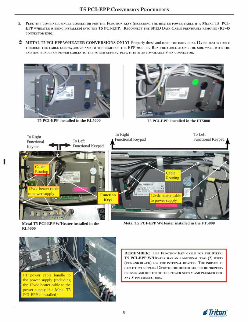
5. PlUg THE CoMBInEd, sInglE ConnECTor For THE FUnCTIon kEys (InClUdIng THE HEaTEr PowEr CaBlE IF a METal T5 PCI-EPP w/HEaTEr Is BEIng InsTallEd) InTo THE T5 PCI-EPP. rEConnECT THE sPEd daTa CaBlE PrEvIoUsly rEMovEd (rj-45 ConnECTor End).
T5 PCI-EPP installed in the RL5000 T5 PCI-EPP installed in the FT5000
rEMEMBEr: THE FUnCTIon kEy CaBlE For THE METal T5 PCI-EPP w/HEaTEr Has an addITIonal Two (2) wIrEs (rEd and BlaCk) For THE InTErnal HEaTEr. THE IndIvIdUal CaBlE THaT sUPPlIEs 12vdC To THE HEaTEr sHoUld BE ProPErly drEssEs and roUTEd To THE PowEr sUPPly and PlUggEd InTo any 8-PIn ConnECTors.
METAL T5 PCI-EPP W/HEATER CONVERSIONS ONLY! Properly dress and route THE IndIvIdUal 12vdC HEaTEr CaBlE THroUgH THE CaBlE gUIdEs, aBovE and To THE rIgHT oF THE EPP ModUlE. rUn THE CaBlE along THE sIdE wall wITH THE ExIsTIng BUndlE oF PowEr CaBlEs To THE PowEr sUPPly. PlUg IT InTo any avaIlaBlE 8 PIn ConnECTor.
FT power cable bundle to the power supply (including the 12vdc heater cable to the power supply if a Metal T5 PCI-EPP is installed}
Metal T5 PCI-EPP W/Heater installed in the RL5000
To Right Functional Keypad
To Left Functional Keypad
Cable Routing
12vdc heater cable to power supply Function
Keys

10
T5 PCI-EPP ConvErsIon ProCEdUrEs
4. dIsConnECT/rEMovE THE ExIsTIng FUnCTIon kEy CaBlEs:
noTETHE rl2000 Is EqUIPPEd wITH EITHEr a 5.7” or 8” dIsPlay. aCCEss To THE FUnCTIon kEy CaBlEs May/wIll rEqUIrE rEMoval oF oTHEr CoMPonEnTs.
Gnd wire connection
NOTE: Before proceeding with the hardware upgrade procedures, terminal power MUST be removed. Enter ManageMenT FuncTions > sysTeM ParaMeTers > shuT Down The TerMinal. When prompted “It is now safe to turn off your computer”on the screen, open the control panel and turn the power switch on the power supply to the <OFF> (0) position.
1. dIsConnECT THE THrEE (3) CaBlEs FroM THE vEPP sPEd assEMBly (2 FUnCTIon kEy, 1 daTa CaBlE sHown BElow). PUll THE (2) FUnCTIon kEy CaBlEs oUT oF THE FlEx TUBIng. yoU wIll HavE To CUT THE Ty wraP THaT sECUrEs THE BUndlEd CaBlEs.
rl2000 uniTs
2. rEMovE THE sIx (6) MoUnTIng sCrEws and groUnd wIrE (as sHown ) THaT sECUrE THE sPEd assEMBly.
3. rEMovE THE vEPP sPEd assEMBly and InsTall THE T5 PCI-EPP. sECUrE wITH THE sIx (6) sCrEws InClUdEd In kIT (k40x20, PT FasTEnEr sCrEw). noTE: rEMEMBEr To rEsECUrE THE groUnd wIrE. vIEw FIgUrE BElow.
** IMPORTANT **The K40x20 PT Fastener (included in the kit) should always be used to secure PCI-EPP’s with ground wire connections!

11
T5 PCI-EPP ConvErsIon ProCEdUrEs
8” Display Assembly.
lIFT grEEn HandlE TaB on x2 MaIn Board and slIdE assEMBly BaCk. rEMovE x2 MaIn Board FroM THE doCkIng Board BraCkET. THE ‘rIgHT’ sIdE FUnCTIon kEy CaBlE Can BE aCCEssEd In THE arEa sHown In FIgUrE BElow rIgHT.
8” dIsPlay FUnCTIon kEy CaBlEs (rEMovE/rEPlaCE):
THE FIgUrEs BElow ProvIdE a BasIC vIEw oF wHErE THE FUnCTIon kEys arE In rElaTIon To THE dIsPlay CasE.
dIsConnECT THE “rIgHT” sIdE FUnCTIon kEy CaBlE sHown . nExT, dIsConnECT THE ‘lEFT’ sIdE FUnCTIon kEy CaBlE sHown. rEMovE THEsE CaBlEs FroM THE ConTrol PanEl. noTe: you May haVe To cuT soMe Ty wraPs To reMoVe.
Right side cable location. Left side cable location.
12
T5 PCI-EPP ConvErsIon ProCEdUrEs
rEInsTall THE x2 MaIn Board assEMBly.
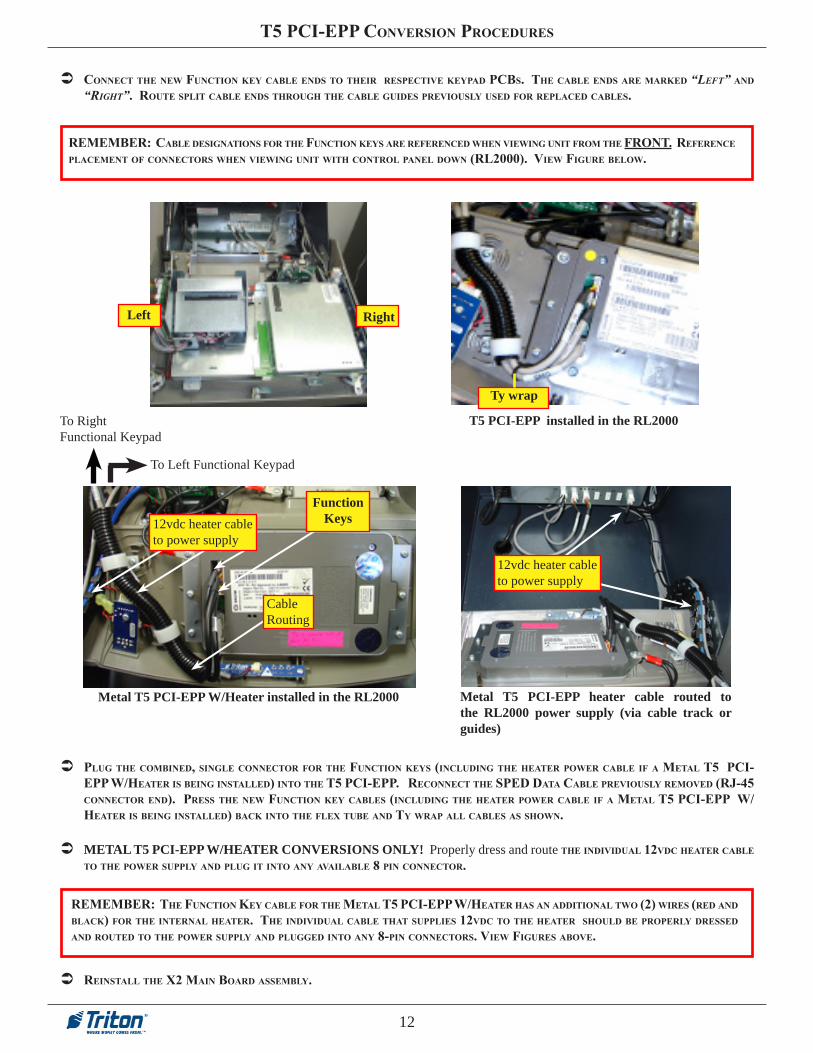
PlUg THE CoMBInEd, sInglE ConnECTor For THE FUnCTIon kEys (InClUdIng THE HEaTEr PowEr CaBlE IF a METal T5 PCI-EPP w/HEaTEr Is BEIng InsTallEd) InTo THE T5 PCI-EPP. rEConnECT THE sPEd daTa CaBlE PrEvIoUsly rEMovEd (rj-45 ConnECTor End). PrEss THE nEw FUnCTIon kEy CaBlEs (InClUdIng THE HEaTEr PowEr CaBlE IF a METal T5 PCI-EPP w/HEaTEr Is BEIng InsTallEd) BaCk InTo THE FlEx TUBE and Ty wraP all CaBlEs as sHown.
ConnECT THE nEw FUnCTIon kEy CaBlE Ends To THEIr rEsPECTIvE kEyPad PCBs. THE CaBlE Ends arE MarkEd “leFT” and “righT”. roUTE sPlIT CaBlE Ends THroUgH THE CaBlE gUIdEs PrEvIoUsly UsEd For rEPlaCEd CaBlEs.
rEMEMBEr: CaBlE dEsIgnaTIons For THE FUnCTIon kEys arE rEFErEnCEd wHEn vIEwIng UnIT FroM THE FronT. rEFErEnCE PlaCEMEnT oF ConnECTors wHEn vIEwIng UnIT wITH ConTrol PanEl down (rl2000). vIEw FIgUrE BElow.
Left Right
Ty wrap
T5 PCI-EPP installed in the RL2000
METAL T5 PCI-EPP W/HEATER CONVERSIONS ONLY! Properly dress and route THE IndIvIdUal 12vdC HEaTEr CaBlE To THE PowEr sUPPly and PlUg IT InTo any avaIlaBlE 8 PIn ConnECTor.
rEMEMBEr: THE FUnCTIon kEy CaBlE For THE METal T5 PCI-EPP w/HEaTEr Has an addITIonal Two (2) wIrEs (rEd and BlaCk) For THE InTErnal HEaTEr. THE IndIvIdUal CaBlE THaT sUPPlIEs 12vdC To THE HEaTEr sHoUld BE ProPErly drEssEd and roUTEd To THE PowEr sUPPly and PlUggEd InTo any 8-PIn ConnECTors. vIEw FIgUrEs aBovE.
Metal T5 PCI-EPP heater cable routed to the RL2000 power supply (via cable track or guides)
12vdc heater cable to power supply
Function Keys
Metal T5 PCI-EPP W/Heater installed in the RL2000
12vdc heater cable to power supply
Cable Routing
To Right Functional Keypad
To Left Functional Keypad

13
T5 PCI-EPP ConvErsIon ProCEdUrEs
lIFT grEEn HandlE TaB on x2 MaIn Board and slIdE assEMBly BaCk. rEMovE x2 MaIn Board FroM THE doCkIng Board BraCkET.
5.7” Display Assembly.
5.7” dIsPlay FUnCTIon kEy CaBlEs (rEMovE/rEPlaCE):
THE FIgUrEs BElow ProvIdE a BasIC vIEw oF wHErE THE FUnCTIon kEys arE In rElaTIon To THE dIsPlay CasE.
Left Right

14
T5 PCI-EPP ConvErsIon ProCEdUrEs
rEMovE sCrEws FroM THE dIsPlay assEMBly - UsIng THE FIgUrE aT lowEr rIgHT as a gUIdE, rEMovE THE FoUr (4) PHIllIPs-HEad sCrEws FroM THE dIsPlay assEMBly. THE FIgUrE BElow lEFT sHows THE aCCEss HolE loCaTIons on THE dIsPlay BraCkET.
“genTly” lIFT THE dIsPlay assEMBly UP To gET aCCEss To THE FUnCTIon kEy CaBlEs. dIsConnECT and rEMovE THEsE CaBlEs FroM THE ConTrol PanEl. noTe: you May haVe To cuT soMe Ty wraPs To reMoVe.
Left Right
*** CAUTION *** When lifting the Display assembly, secure the display glass with one hand to prevent glass from possibly separating from display and breaking.

15
T5 PCI-EPP ConvErsIon ProCEdUrEs
lIFTIng THE dIsPlay assEMBly agaIn, ConnECT THE nEw FUnCTIon kEy CaBlE Ends To THEIr rEsPECTIvE kEyPad PCBs. THE CaBlE Ends arE MarkEd “leFT” and “righT”. roUTE sPlIT CaBlE Ends THroUgH THE CaBlE gUIdEs PrEvIoUsly UsEd For rEPlaCEd CaBlEs.
rEMEMBEr: CaBlE dEsIgnaTIons For THE FUnCTIon kEys arE rEFErEnCEd wHEn vIEwIng UnIT FroM THE FronT. rEFErEnCE PlaCEMEnT oF ConnECTors wHEn vIEwIng UnIT wITH ConTrol PanEl down (rl2000). vIEw FIgUrE BElow.
sECUrE THE dIsPlay assEMBly To THE ConTrol PanEl wITH THE FoUr (4) sCrEws PrEvIoUsly rEMovEd.
rEInsTall THE x2 MaIn Board assEMBly.
Ty wrap
T5 PCI-EPP installed in the RL 2000
PlUg THE CoMBInEd, sInglE ConnECTor For THE FUnCTIon kEys (InClUdIng THE HEaTEr PowEr CaBlE IF a METal T5 PCI-EPP w/HEaTEr Is BEIng InsTallEd) InTo THE T5 PCI-EPP. rEConnECT THE sPEd daTa CaBlE PrEvIoUsly rEMovEd (rj-45 ConnECTor End). PrEss THE nEw FUnCTIon kEy CaBlEs (InClUdIng THE HEaTEr PowEr CaBlE IF a METal T5 PCI-EPP w/HEaTEr Is BEIng InsTallEd) BaCk InTo THE FlEx TUBE and Ty wraP all CaBlEs as sHown.
METAL T5 PCI-EPP W/HEATER CONVERSIONS ONLY! Properly dress and route THE IndIvIdUal 12vdC HEaTEr CaBlE To THE PowEr sUPPly and PlUg IT InTo any avaIlaBlE 8 PIn ConnECTor.
12vdc heater cable to power supply
Metal T5 PCI-EPP heater cable routed to the RL2000 power supply (via cable track or guides)
rEMEMBEr: THE FUnCTIon kEy CaBlE For THE METal T5 PCI-EPP w/HEaTEr Has an addITIonal Two (2) wIrEs (rEd and BlaCk) For THE InTErnal HEaTEr. THE IndIvIdUal CaBlE THaT sUPPlIEs 12vdC To THE HEaTEr sHoUld BE ProPErly drEssEs and roUTEd To THE PowEr sUPPly and PlUggEd InTo any 8-PIn ConnECTors. vIEw FIgUrEs aBovE.
Metal T5 PCI-EPP W/Heater installed in the RL2000
Function Keys12vdc heater cable
to power supply
Cable Routing
To Right Functional Keypad
To Left Functional Keypad
16
T5 PCI-EPP ConvErsIon ProCEdUrEs
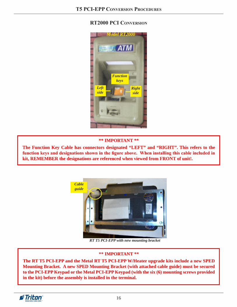
rT2000 PCI ConvErsIon
Model RT2000
Left side
Function keys
Right side
** IMPORTANT **The Function Key Cable has connectors designated “LEFT” and “RIGHT”. This refers to the function keys and designations shown in the figure above. When installing this cable included in kit, REMEMBER the designations are referenced when viewed from FRONT of unit!.
RT T5 PCI-EPP with new mounting bracket
Cable guide
** IMPORTANT **The RT T5 PCI-EPP and the Metal RT T5 PCI-EPP W/Heater upgrade kits include a new SPED Mounting Bracket. A new SPED Mounting Bracket (with attached cable guide) must be secured to the PCI-EPP Keypad or the Metal PCI-EPP Keypad (with the six (6) mounting screws provided in the kit) before the assembly is installed in the terminal.

17
T5 PCI-EPP ConvErsIon ProCEdUrEs
TOOLS REQUIRED
Phillips Screwdriver (Magnetic)
RT T5 PCI-EPP UPGRADE KIT (Model RT2XXX)
06200-08135 (UK) 06200-08137 (US) 06200-08139 (CAN) 06200-08143 (NETH)
PARTS SUPPLIED
PART NUMBER DESCRIPTION QUANTITY
1 03016-20XXX Keypad, PCI-EPP (Encrypting PIN Pad) 1
09120-07070 Dewhurst SPED Cable (Function Keys) 1
3011-05219 SPED Mounting Bracket 1
05200-10033 RL/FT/RT Software CD(includes kit #’s, install guides, software) 1
1 Country specified
RT Metal T5 PCI-EPP W/HEATER UPGRADE KITS (Model RT2XXX)
06200-08163 (UK) 06200-08169 (US) 06200-08170 (CAN) 06200-08172 (NETH)
PARTS SUPPLIED
PART NUMBER DESCRIPTION QUANTITY
1 03016-25XXX Metal Keypad, PCI-EPP (Encrypting PIN Pad) W/Heater 1
09120-07080 Keypad Heater Cable (w/Function Keys) 1
03072-00015 Ty Wraps - 6 inches 10
3011-05219 SPED Mounting Bracket 1
05200-10033 RL/FT/RT Software CD(includes kit #’s, install guides, software) 1
1 Country specified

18
T5 PCI-EPP ConvErsIon ProCEdUrEs
NOTE: Before proceeding with the hardware upgrade procedures, terminal power MUST be removed. Enter ManageMenT FuncTions > sysTeM ParaMeTers > shuT Down The TerMinal. When prompted “It is now safe to turn off your computer”on the screen, open the rear cabinet door and turn the power switch on the power supply to the <OFF> (0) position.
rT2000 UnIT:1. oPEn THE vaUlT door and slIdE THE dIsPEnsEr oUT. on THE ConTrol PanEl, dIsConnECT THE Two (2) FUnCTIon kEy CaBlEs.
THEsE CaBlEs wIll BE rEPlaCEd. THE FIgUrE BElow ProvIdEs a rEFErEnCE For THE loCaTIon oF THE CaBlE ConnECTIons.
2. FInd THE grEEn HandlE THaT oPEraTEs THE dEvICE THaT sECUrEs THE vIsa EPP (sPEd) ModUlE InTo THE ConTrol PanEl. IT Is loCaTEd BEHInd and To THE rIgHT oF THE lowEr rIgHT CornEr oF THE dIsPlay assEMBly. PUll down on THE grEEn HandlE To rElEasE THE EPP ModUlE.
3. CarEFUlly rEMovE THE EPP and ITs MoUnTIng BraCkET. wHEn THE assEMBly Is ClEar oF THE ConTrol PanEl, TUrn IT ovEr and dIsConnECT THE THrEE (3) CaBlEs FroM THE EPP (2 FUnCTIon kEy, 1 daTa CaBlE). rEMovE THE EPP ModUlE and MoUnTIng BraCkET FroM THE aTM. sInCE THEy wIll noT BE rEUsEd, Ty wraP THE Two (2) orIgInal FUnCTIon kEy CaBlEs To THE sPlIT FlEx TUBIng so THEy wIll BE oUT oF THE way.

19
T5 PCI-EPP ConvErsIon ProCEdUrEs
4. PlaCE THE EPP assEMBly on a FlaT sUrFaCE. rEMovE and rETaIn THE sIx (6) sCrEws and nUTs THaT sECUrE THE EPP To THE MoUnTIng BraCkET. rEMovE and rETaIn THE CaBlE gUIdE. THE T5 PCI-EPP rEqUIrEs a nEw sPEd MoUnTIng BraCkET (InClUdEd In THE kIT).
5. MoUnT THE nEw sPEd BraCkET To THE T5 PCI-EPP as sHown BElow. sECUrE wITH THE orIgInal sIx (6) sCrEws and nUTs PrEvIoUsly rEMovEd. rEMEMBEr To rEInsTall THE CaBlE gUIdE on THE nEw sPEd MoUnTIng BraCkET
7. Make sure THE Two (2) orIgInal FUnCTIon kEy CaBlEs HavE BEEn Ty wraPPEd so THEy arE oUT oF THE way. MovE THE T5 PCI-EPP assEMBly (sTEP 5) BaCk To THE UnIT. PlUg THE CoMBInEd, sInglE ConnECTor For THE FUnCTIon kEys (InClUdIng THE HEaTEr PowEr CaBlE IF a METal T5 PCI-EPP w/HEaTEr Is BEIng InsTallEd) InTo THE T5 PCI-EPP. rEConnECT THE sPEd daTa CaBlE PrEvIoUsly rEMovEd (rj-45 ConnECTor End).
VEPP with mounting bracket T5 PCI-EPP with new mounting bracket
Cable guide
6. ConnECT THE nEw FUnCTIon kEy CaBlE Ends To THEIr rEsPECTIvE kEyPad PCBs. THE CaBlE Ends arE MarkEd “leFT” and “righT”. drEss, BUndlE, and roUTE THE FUnCTIon kEy CaBlEs (InClUdIng THE HEaTEr PowEr CaBlE IF a METal T5 PCI-EPP w/HEaTEr Is BEIng InsTallEd) so THEy Follow THE sPlIT FlEx TUBIng down To THE sPEd ConnECTor.
rEMEMBEr: CaBlE dEsIgnaTIons For THE FUnCTIon kEys arE rEFErEnCEd wHEn vIEwIng UnIT FroM THE FronT. rEFErEnCE PlaCEMEnT oF ConnECTors wHEn vIEwIng FroM rEar oF THE ConTrol PanEl (rT2000). vIEw FIgUrE BElow.
8. TUrn THE assEMBly ovEr so THE kEyPad Is FaCIng UP . slIdE THE assEMBly BaCk InTo THE ConTrol PanEl and sECUrE By PUllIng THE grEEn HandlE UP. rEFErEnCE sTEPs 3 and 2 For rEInsTallIng sPEd assEMBly.
9. slIdE THE dIsPEnsEr BaCk InTo THE CaBInET.
rEMEMBEr: THE FUnCTIon kEy CaBlE For THE METal T5 PCI-EPP w/HEaTEr Has an addITIonal Two (2) wIrEs (rEd and BlaCk) For THE InTErnal HEaTEr. THE IndIvIdUal CaBlE THaT sUPPlIEs 12vdC To THE HEaTEr sHoUld BE ProPErly drEssEs and roUTEd To THE PowEr sUPPly and PlUggEd InTo any 8-PIn ConnECTors. vIEw FIgUrEs aBovE.
METAL T5 PCI-EPP W/HEATER CONVERSIONS ONLY! Properly dress, and route THE IndIvIdUal 12vdC HEaTEr CaBlE so IT Follows THE PowEr CaBlE BUndlE In THE sPlIT FlEx TUBIng To THE PowEr sUPPly. PlUg IT InTo any avaIlaBlE 8 PIn ConnECTor.
Right
Left
RT Power cable bundle to the power supply (including the 12vdc heater cable to the power supply if a Metal T5 PCI-EPP is installed

20
T5 PCI-EPP ConvErsIon ProCEdUrEs
BaTTEry rEPlaCEMEnT ProCEdUrEs

21
T5 PCI-EPP ConvErsIon ProCEdUrEs
EXISTING BATTERY - DO NOT REMOVE BEFORE CONNECTING A SPARE BATTERY FIRST!
Spare battery connection
Battery Case
** WARNING ** You must not remove battery from EPP without FIRST connecting a new battery! This EPP will be permanently damaged if unpowered and battery is removed before connecting a new battery!

APPENDIX A
A-2
T5 PCI-EPP CONVERSION PROCEDURES
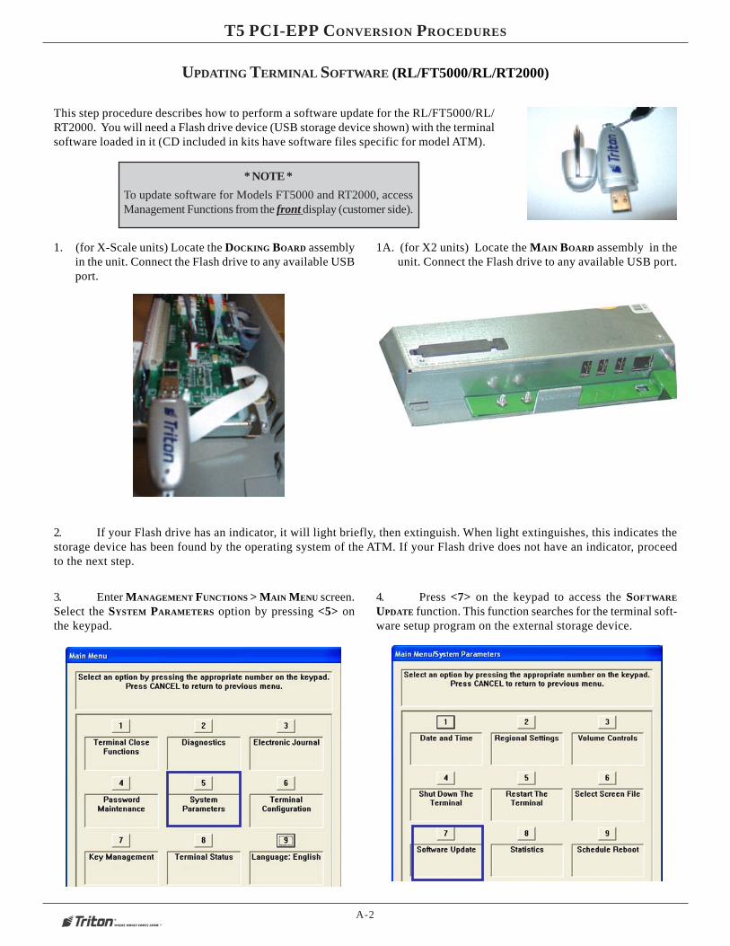
UPDATING TERMINAL SOFTWARE (RL/FT5000/RL/RT2000)
This step procedure describes how to perform a software update for the RL/FT5000/RL/RT2000. You will need a Flash drive device (USB storage device shown) with the terminalsoftware loaded in it (CD included in kits have software files specific for model ATM).
1. (for X-Scale units) Locate the DOCKING BOARD assemblyin the unit. Connect the Flash drive to any available USBport.
1A. (for X2 units) Locate the MAIN BOARD assembly in theunit. Connect the Flash drive to any available USB port.
2. If your Flash drive has an indicator, it will light briefly, then extinguish. When light extinguishes, this indicates thestorage device has been found by the operating system of the ATM. If your Flash drive does not have an indicator, proceedto the next step.
3. Enter MANAGEMENT FUNCTIONS > MAIN MENU screen.Select the SYSTEM PARAMETERS option by pressing <5> onthe keypad.
4. Press <7> on the keypad to access the SOFTWARE
UPDATE function. This function searches for the terminal soft-ware setup program on the external storage device.
* NOTE *
To update software for Models FT5000 and RT2000, accessManagement Functions from the front display (customer side).

A-3
APPENDIX A - LOADING SOFTWARE / KEY MANAGEMENT PROCEDURES
7. Use the left and right <ARROW> keys on the keypad tohighlight the selected file. Press <ENTER> when selected.
8. A screen will appear verifying the selected file and prompt to restart the terminal.Press <ENTER> to continue.
9. The terminal will restart at this time and the installation of the software will beperformed automatically. After the terminal completes it’s reboot sequence, remove theFlash drive device. NOTE: An additional restart is recommended after the file is loaded.
5. In the “LOOK IN” option should be the “USB” location. If it’s not present, <CANCEL> out of the Software Updatescreen and then re-enter the same screen.
6. When the “LOOK IN” option has “USB” present, the “FILENAME” screen should have the terminal software, size, anddate/time attributes for each file loaded in the Flash drive. See NOTE, below.
* NOTE *(FULL LOAD FILES)
When loading a Full Load software file, you will losepreviously configured parameters and will have toreconfigure. It is HIGHLY recommended saving parametersMAIN MENU > TERMINAL STATUS > SAVE PARAMETERS TO
EXTERNAL STORAGE (USB DEVICE) before loading the Full Loadfile. This allows you to quickly reconfigure terminal with thesaved parameters.
Legend:
Full load files are identified with a ‘D’ designation (XD).
X-Scale units software is identified with a .TLF extension.
X2 unit s software is identified with a .TFV extension.
LOADING THE X2 MULTITECH MODEM CONFIGURATION FILE
(REQUIRED FOR X2 UNITS THAT EMPLOY THE MULTITECH USB MODEM)
If you converted your X-Scale units to X2 but you did not require the optional Triton modem upgrade and are using a Multitech USBmodem instead, you will need to load a configuration file for the Multitech USB modem. This software load (patch) should beaccomplished after loading the terminal software.
1. Follow the same procedures in the “Updating Terminal Soft-ware” instructions. Highlight/select the following file:
X2MultitechModemCfg.tfv
2. A screen will appear at right verifying the selected file.Press <ENTER> to continue.
3. The terminal will restart at this time and the installation of the software will be performed automatically. After the terminalcompletes it’s reboot sequence, remove the Flash drive device.
A-4
T5 PCI-EPP CONVERSION PROCEDURES
SAVE JOURNAL RECORDS
DESCRIPTION:
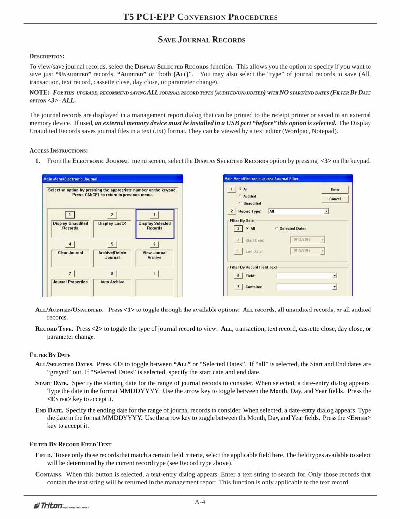
To view/save journal records, select the DISPLAY SELECTED RECORDS function. This allows you the option to specify if you want tosave just “UNAUDITED” records, “AUDITED” or “both (ALL)”. You may also select the “type” of journal records to save (All,transaction, text record, cassette close, day close, or parameter change).
NOTE: FOR THIS UPGRADE, RECOMMEND SAVING ALL JOURNAL RECORD TYPES (AUDITED/UNAUDITED) WITH NO START/END DATES (FILTER BY DATE
OPTION <3> - ALL.
The journal records are displayed in a management report dialog that can be printed to the receipt printer or saved to an externalmemory device. If used, an external memory device must be installed in a USB port “before” this option is selected. The DisplayUnaudited Records saves journal files in a text (.txt) format. They can be viewed by a text editor (Wordpad, Notepad).
ACCESS INSTRUCTIONS:
1. From the ELECTRONIC JOURNAL menu screen, select the DISPLAY SELECTED RECORDS option by pressing <3> on the keypad.
ALL/AUDITED/UNAUDITED. Press <1> to toggle through the available options: ALL records, all unaudited records, or all auditedrecords.
RECORD TYPE. Press <2> to toggle the type of journal record to view: ALL, transaction, text record, cassette close, day close, orparameter change.
FILTER BY DATE
ALL/SELECTED DATES. Press <3> to toggle between “ALL” or “Selected Dates”. If “all” is selected, the Start and End dates are“grayed” out. If “Selected Dates” is selected, specify the start date and end date.
START DATE. Specify the starting date for the range of journal records to consider. When selected, a date-entry dialog appears.Type the date in the format MMDDYYYY. Use the arrow key to toggle between the Month, Day, and Year fields. Press the<ENTER> key to accept it.
END DATE. Specify the ending date for the range of journal records to consider. When selected, a date-entry dialog appears. Typethe date in the format MMDDYYYY. Use the arrow key to toggle between the Month, Day, and Year fields. Press the <ENTER>key to accept it.
FILTER BY RECORD FIELD TEXT
FIELD. To see only those records that match a certain field criteria, select the applicable field here. The field types available to selectwill be determined by the current record type (see Record type above).
CONTAINS. When this button is selected, a text-entry dialog appears. Enter a text string to search for. Only those records thatcontain the text string will be returned in the management report. This function is only applicable to the text record.

A-5
APPENDIX A - LOADING SOFTWARE / KEY MANAGEMENT PROCEDURES
The report is displayed in a management report dialog that can be printed to the receipt printer or saved to an external memory device.The DISPLAY SELECTED RECORDS options save Journal files in a text (.txt) format. They can be viewed by a text editor.
� Press <6> to “SAVE TO FILE”. The following prompt will appear:
Note: With an external storage device installed, the prompt will bedisplay like the example below:
“\Hard Disk\071983179_20070912103959.txt”
� Press <ENTER> to continue and save the journal records.
A-6
T5 PCI-EPP CONVERSION PROCEDURES
SAVE / RESTORE PARAMETERS USING AN EXTERNAL STORAGE
DESCRIPTION:
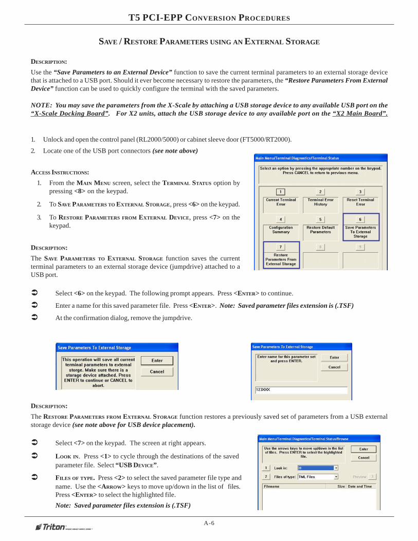
Use the “Save Parameters to an External Device” function to save the current terminal parameters to an external storage devicethat is attached to a USB port. Should it ever become necessary to restore the parameters, the “Restore Parameters From ExternalDevice” function can be used to quickly configure the terminal with the saved parameters.
NOTE: You may save the parameters from the X-Scale by attaching a USB storage device to any available USB port on the“X-Scale Docking Board”. For X2 units, attach the USB storage device to any available port on the “X2 Main Board”.
ACCESS INSTRUCTIONS:
1. From the MAIN MENU screen, select the TERMINAL STATUS option bypressing <8> on the keypad.
2. To SAVE PARAMETERS TO EXTERNAL STORAGE, press <6> on the keypad.
3. To RESTORE PARAMETERS FROM EXTERNAL DEVICE, press <7> on thekeypad.
� Select <6> on the keypad. The following prompt appears. Press <ENTER> to continue.
� Enter a name for this saved parameter file. Press <ENTER>. Note: Saved parameter files extension is (.TSF)
� At the confirmation dialog, remove the jumpdrive.
DESCRIPTION:
The RESTORE PARAMETERS FROM EXTERNAL STORAGE function restores a previously saved set of parameters from a USB externalstorage device (see note above for USB device placement).
� Select <7> on the keypad. The screen at right appears.
� LOOK IN. Press <1> to cycle through the destinations of the savedparameter file. Select “USB DEVICE”.
� FILES OF TYPE. Press <2> to select the saved parameter file type andname. Use the <ARROW> keys to move up/down in the list of files.Press <ENTER> to select the highlighted file.
Note: Saved parameter files extension is (.TSF)
DESCRIPTION:
The SAVE PARAMETERS TO EXTERNAL STORAGE function saves the currentterminal parameters to an external storage device (jumpdrive) attached to aUSB port.
1. Unlock and open the control panel (RL2000/5000) or cabinet sleeve door (FT5000/RT2000).
2. Locate one of the USB port connectors (see note above)
A-7
APPENDIX A - LOADING SOFTWARE / KEY MANAGEMENT PROCEDURES
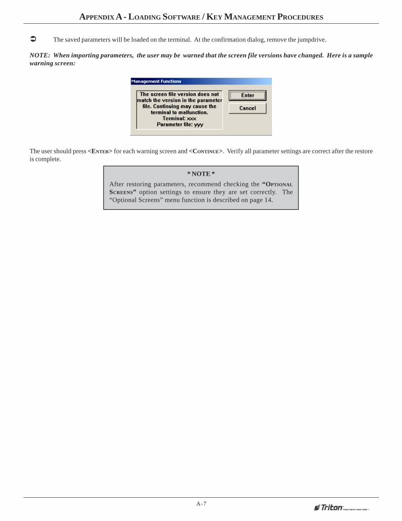
NOTE: When importing parameters, the user may be warned that the screen file versions have changed. Here is a samplewarning screen:
The user should press <ENTER> for each warning screen and <CONTINUE>. Verify all parameter settings are correct after the restoreis complete.
� The saved parameters will be loaded on the terminal. At the confirmation dialog, remove the jumpdrive.
* NOTE *
After restoring parameters, recommend checking the “OPTIONAL
SCREENS” option settings to ensure they are set correctly. The“Optional Screens” menu function is described on page 14.

A-8
T5 PCI-EPP CONVERSION PROCEDURES
Clear Serial #Error
4
CLEAR SERIAL # ERROR
After installing the T5 PCI-EPP, you will get a “Serial # Error”. In this event (and you must clear this error before enteringkeys in Key Management), option <4> will be an available option (active). Select this option to clear the error. The option willrevert to “Grayed” out if the error hass been cleared.
ACCESS INSTRUCTIONS:
1. From the MAIN MENU screen, select DIAGNOSTICS by pressing <2> on the keypad.
2. Select KEYPAD by pressing <8> on the keypad.
3. Select option <4> if active to clear Serial # error.

A-9
APPENDIX A - LOADING SOFTWARE / KEY MANAGEMENT PROCEDURES
DIFFERENCES WITH THE T5 PCI-EPP KEYPAD
�
PCI-EPP (T5) / KEY MANAGEMENT PROCEDURES
� USER PASSWORDS MUST BE AT LEAST 8 CHARACTERS, RATHER THAN 6.
� EPP WILL PROMPT WITH ERROR IF FEWER CHARACTERS ENTERED AND THEN TAKE YOU BACK TO PASSWORD
ENTRY AT POINT YOU LEFT OFF.
� THERE IS NO WAY TO CLEAR THE PASSWORD. HIT <CANCEL> AND START OVER.
�
� NO <CLEAR> OR <BACKSPACE> ON KEY ENTRY.
� IF ERROR IS MADE IN KEY ENTRY, HIT <CANCEL> AND START KEY ENTRY OVER FROM BEGINNING OF FIRST KEY
HALF.
�
� YOU MAY ONLY ENTER IN NEW KEYS - NO CHANGE KEY FUNCTIONALITY.
�
� YOU HAVE 10 MINUTES TO ENTER IN BOTH USER PASSWORDS BEFORE TIMEOUT.
– IF TIMEOUT OCCURS, YOU MUST START KEY ENTRY OVER FROM SCRATCH.
– THIS WILL AFFECT STAGING OF UNITS!
– CANNOT ENTER ONE KEY HALF AT WAREHOUSE AND OTHER HALF IN FIELD.
�
� PASSWORD ENTRY – CLEAR WILL TAKE YOU BACK TO KEY MANAGEMENT PAGE.
– RE-ENTER PASSWORD.
�
YOU MUST NOT REMOVE BATTERY FROM EPP WITHOUT FIRST CONNECTING A NEW BATTERY! THIS
T5 EPP WILL BE PERMANENTLY DAMAGED IF UNPOWERED AND BATTERY IS REMOVED BEFORE CONNECTING A NEW
BATTERY!
MOST IMPORTANT NOTE:
This version of software changes the requirement to enter 6 (six) zeros before changing the keypadpasswords. The keypads are shipped with NO PREASSIGNED PASSWORDS. IF YOU EN-TER 6 (SIX) ZEROS AS WITH PREVIOUS VERSIONS OF SOFTWARE, THAT WILL BETHE PASSWORD AND CANNOT BE CHANGED IN THE FIELD. ONCE ANY PASSWORDIS ENTERED, IT CAN NOT BE CHANGED IN THE FIELD!!!!

A-10
T5 PCI-EPP CONVERSION PROCEDURES
� ENTER MANAGEMENT FUNCTIONS > MAIN MENU
> KEY MANAGEMENT.
� THE “SET PASSWORD INITIALIZATION” PROMPT
APPEARS. PRESS <ENTER>.
� SELECT “SET PASSWORD” OPTION.
� NOTE: PREVIOUSLY, USERS HAD TO ENTER THE
INITIAL PASSWORD OF SIX (6) “ZEROS” BEFORE BEING
ALLOWED TO SET THE PASSWORDS. THIS IS NO LONGER
REQUIRED.
� SELECT “SET USER 1 PASSWORD” OPTION.ENTER NEW PASSWORD FOR USER 1. PASSWORDS CAN
BE ANYWHERE FROM ‘8’ TO ‘16’ DECIMAL DIGITS. PRESS
<ENTER>.
� YOU WILL BE PROMPTED AGAIN TO CONFIRM
THE NEW PASSWORD. RE-ENTER NEW PASSWORD.PRESS <ENTER>.
� NEXT, SELECT “SET USER 2 PASSWORD” OP-TION. FOLLOW THE SAME PROCEDURE FOR ENTERING ANEW PASSWORD FOR USER 2.
WHEN COMPLETED, THE “SET USER 2 PASSWORD” OP-TION WILL CHANGE TO “CHANGE USER 2 PASSWORD”.
AFTER COMPLETION, HIT <CANCEL> TO ENTER MAS-TER KEYS SCREEN (STEP 5).
AFTER THE PASSWORD IS INITIALIZED, THE “SET USER
1 PASSWORD” OPTION CHANGES TO “CHANGE USER 1PASSWORD”.
READ MOST IMPORTANT NOTE ONPREVIOUS PAGE BEFORE PROCEED-ING

A-11
APPENDIX A - LOADING SOFTWARE / KEY MANAGEMENT PROCEDURES
� SELECT “ENTER MASTER KEYS” OPTION.
IMPORTANT: THE REST OF THE PROCEDURES
MUST BE COMPLETED WITHIN A 10MINUTE PERIOD. IF THE PROCESS TAKES
LONGER THAN THAT, THE KEY PARTS WILL NOT BE ABLE
TO BE COMBINED!
� ENTER USER 1 PASSWORD. PRESS <ENTER>.ENTER USER 2 PASSWORD. PRESS <ENTER>.
� SELECT “ENTER PIN MASTER KEY” OPTION.
USER 1 ENTERS THE FIRST KEY PART (32 CHAR-ACTERS). REFERENCE THE KEY LAYOUT DISPLAY BELOW.THE MAIN KEYPAD WILL MIRROR THE NUMBER/ALPHA-NUMERIC KEYS.
AFTER ENTERING THE KEYS, PRESS THE <ENTER> OP-TION ON THE RIGHT-SIDE FUNCTION KEY <F7>.
F5
F7

A-12
T5 PCI-EPP CONVERSION PROCEDURES
THE “CHECK DIGITS” PROMPT APPEARS.PRESS <ENTER>.
A PROMPT APPEARS TO ENTER THE SECOND KEY PART.PRESS <ENTER>.
� USER 2 ENTERS THE SECOND KEY PART (32 CHAR-ACTERS). REFER TO STEP 8 FOR ENTERING KEYS.
THE “CHECK DIGITS” PROMPT APPEARS.
YOU WILL BE PROMPTED THAT THE KEY WAS SUCCESS-FULLY CHANGED.
REPEAT SEQUENCE FOR ENTERING MAC MASTER KEY ,IF REQUIRED.
11

A-13
APPENDIX A - LOADING SOFTWARE / KEY MANAGEMENT PROCEDURES
CHECK OPERATION OF PRINTER/PRESENTER
1. Enter MANAGEMENT FUNCTIONS > MAIN MENU screen. Select DIAGNOSTICS option <2> , then PRINTER option <6>.
2. Press <1>, DEVICE STATUS. A Management report is displayed.
3. Scroll down to the “PRESENTER INSTALLED” and “PRESENTER STORED” line items. If there is a difference in the status reportbetween either (ex: “Presenter Installed”: YES , “Presenter Stored”: NO), proceed to the next step.
4. Press <3>, CONFIGURE PRINTER. Press the <CLEAR> to scroll down/highlight the “Reset All” option. Press the<ENTER> key.
5. Perform another DEVICE STATUS to verify “Presenter Installed” and “Presenter Stored” status are the same. Also verify if the“Device Status” line item reflects: 0 (Device Ready).
Note: Recommend perform a RESET\TEST PRINTER function <Option 2>. This function re-initializes and performs an operationaltest (printout) of the printer.
A-14
T5 PCI-EPP CONVERSION PROCEDURES
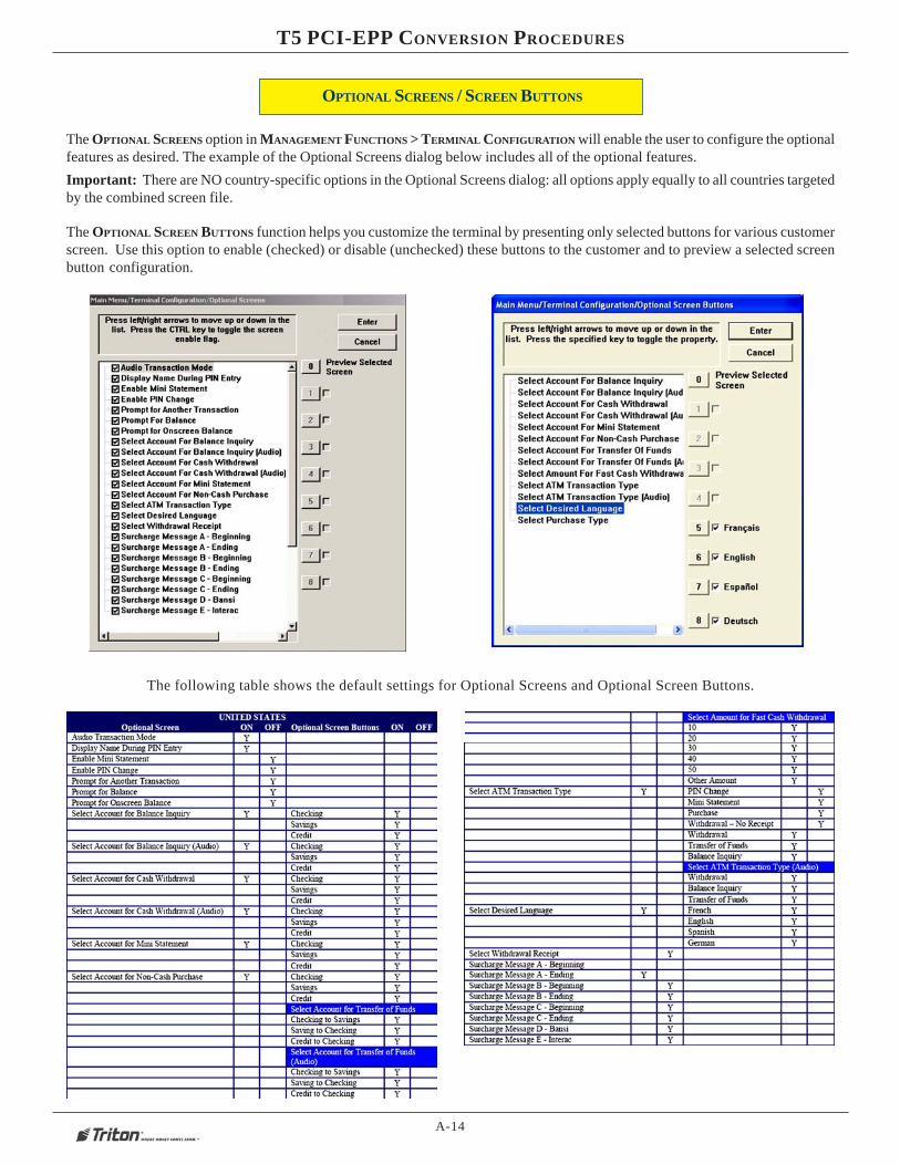
The OPTIONAL SCREENS option in MANAGEMENT FUNCTIONS > TERMINAL CONFIGURATION will enable the user to configure the optionalfeatures as desired. The example of the Optional Screens dialog below includes all of the optional features.
Important: There are NO country-specific options in the Optional Screens dialog: all options apply equally to all countries targetedby the combined screen file.
The OPTIONAL SCREEN BUTTONS function helps you customize the terminal by presenting only selected buttons for various customerscreen. Use this option to enable (checked) or disable (unchecked) these buttons to the customer and to preview a selected screenbutton configuration.
The following table shows the default settings for Optional Screens and Optional Screen Buttons.
OPTIONAL SCREENS / SCREEN BUTTONS