t52-software engineering lecture notes year/software... · 1 t52-software engineering unit ii...
TRANSCRIPT
1
T52-Software Engineering
UNIT II
System Engineering: Requirements elicitation - Need for SRS - Requirement Process- Problem
Analysis – Informal Approach - Cardinality and modality – Entity / Relationship diagram –
Data Flow Modeling - Object-Oriented Modeling - Prototyping - Requirements Specification -
Characteristics of an SRS - Components of an SRS - Specification - Structure of a
Requirements Document - Functional Specification with Use Cases - Extensions - Developing
Use Cases - Requirements analysis and negotiation - Requirements validation - Requirements
management - Joint Application Development.
Objectives:
1.1 System Engineering:
Software engineering occurs as a consequence of a process called system engineering.
Instead of concentrating solely on software, system engineering focuses on variety of
elements, analyzing, designing and organizing those elements into a system that can be a
product, a service, or a technology for the transformation of information or control.
The system engineering process takes on different forms depending on the application
domain in which it is applied.
Business process engineering is conducted when the context of the work focuses on a
business enterprise.
When a product is to be built, the process is called product engineering. Both business process
engineering and product engineering attempts:
To bring order to the development of computer based systems.
Strives to put software.
Allocate role for computer software
To establish the links that the software to the other elements of a computer
based systems.
engineering.
To acquire knowledge about Object Oriented concepts relating to software
To learn about creating SRS document to build the software in an effective way.
2
Software Requirements:
IEEE defines a requirement as ―(1) A condition of capability needed by a user to solve a
problem or achieve an objective; (2) A condition or a capability that must be met or possessed by a
system to satisfy a contract, standard, specification, or other formally imposed document‖.
1.2 Requirements Elicitation:
It involves asking the customer, user, others about fixing the objectives of the system, what is
to be accomplished, how the system (or) product fits into the needs of the business and how the
system (or) product is to be used on a day-day basis.
Christel and Kang identify a number of problems that help us understand why requirements
elicitation is difficult:
Problems of scope:
The boundary of the system is ill-defined or the customers/ users specify unnecessary
technical detail that may confuse, rather than clarify, overall system objectives.
Problems of understanding:
The customers/users have a poor understanding of the capabilities and limitations of
computing environment and don‘t have a full understanding of problem domain. They have trouble in
communicating needs to the system engineer or specify requirements that are ambiguous or
untestable.
Problems of volatility:
The requirements change over time. To help overcome these problems, system engineers
must approach the requirements gathering activity in an organized manner.
1.3 Need for SRS
The origin of most software systems is in the needs of some clients. The software system
itself is created by some developers. Finally, the completed system will be used by the end users.
Thus, there are three major parties interested in a new system: the client, the developer, and the
users. Somehow the requirements for the system that will satisfy the needs of the clients and the
concerns of the users have to be communicated to the developer. The problem is that the client
usually does not understand software or the software development process, and the developer often
does not understand the client's problem and application area. This causes a communication gap
between the parties involved in the development project. A basic purpose of software requirements
specification is to bridge this communication gap.
3
SRS is the medium through which the client and user needs are accurately specified to the developer.
Hence one of the main advantages is:
An SRS establishes the basis for agreement between the client and the supplier on what the
software product will do.
This basis for agreement is frequently formalized into a legal contract between the client (or the
customer) and the developer (the supplier). So, through SRS, the client clearly describes what it
expects, and the developer clearly understands what capabilities to build in the software.
An SRS provides a reference for validation of the final product.
The SRS helps the client determine if the software meets the requirements. Without a proper
SRS, there is no way a client can determine if the software being delivered is what was ordered, and
there is no way the developer can convince the client that the requirements have been fulfilled.
Providing the basis of agreement and validation should be strong enough reasons for both the client
and the developer to do a thorough and rigorous job of requirement understanding and
specification, but there are other very practical and pressing reasons for having a good SRS.
It is clear that many errors are made during the requirements phase. And an error in the SRS with
most likely manifest itself as an error in the final system implementing the SRS; after ah, if the SRS
document specifies a wrong system (i.e., one that will not satisfy the client's objectives), then even a
correct implementation of the SRS will lead to a system that will not satisfy the client. Clearly, if we
want a high-quality end product that has few errors, we must begin with a high-quality SRS.
A high-quality SRS is a prerequisite to high-quality software.
The quality of SRS has an impact on cost (and schedule) of the project. We have already
seen that errors can exist in the SRS. We saw earlier that the cost of fixing an error increases almost
exponentially as time progresses. That is, a requirement error, if detected and removed after the
system has been developed, can cost up to 100 times more than removing it during the requirements
phase itself. The approximate average cost of fixing requirement errors (in person-hours) depending on
the phase is shown in Table.
4
A high quality SRS reduces the development cost.
The quality of the SRS impacts customer and developer satisfaction, system validation,
quality of the final software and the software development cost. The critical role the SRS plays in a
software development project should be evident from these.
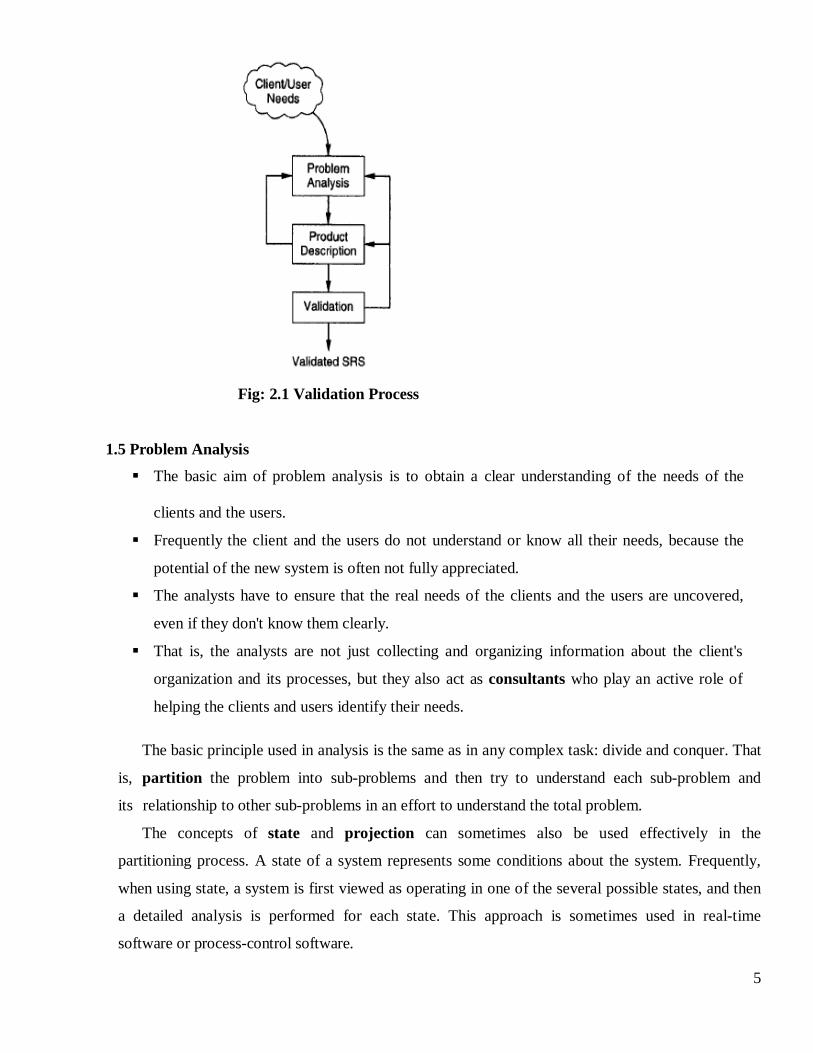
1.4 Requirement Process
The requirement process is the sequence of activities that need to be performed in the
requirements phase and that culminate in producing a high quality document containing the software
requirements specification (SRS). The requirements process typically consists of three basic tasks:
problem or requirement analysis, requirement specification, and requirements validation.
Problem analysis often starts with a high-level "problem statement." During analysis the
problem domain and the environment are modeled in an effort to understand the system behavior,
constraints on the system, its inputs and outputs, etc. The basic purpose of this activity is to obtain a
thorough understanding of what the software needs to provide. The understanding obtained by
problem analysis forms the basis of requirements specification, in which the focus is on clearly
specifying the requirements in a document.
Issues such as representation, specification languages, and tools, are addressed during this activity. As
analysis produces large amounts of information and knowledge with possible redundancies;
properly organizing and describing the requirements is an important goal of this activity.
1.4.1 Requirements validation:
Focuses on ensuring that what has been specified in the SRS are indeed all the requirements of
the software and making sure that the SRS is of good quality. The requirements process terminates with
the production of the validated SRS.
Though it seems that the requirements process is a linear sequence of these three activities, in
reality it is not so for anything other than trivial systems. In most real systems, there is considerable
overlap and feedback between these activities. So, some parts of the system are analyzed and then
specified while the analysis of the other parts is going on. Furthermore, if the validation activities
reveal problems in the SRS, it is likely to lead to further analysis and specification. However, in
general, for a part of the system, analysis precedes specification and specification precedes validation.
5
Fig: 2.1 Validation Process
1.5 Problem Analysis
The basic aim of problem analysis is to obtain a clear understanding of the needs of the
clients and the users.
Frequently the client and the users do not understand or know all their needs, because the
potential of the new system is often not fully appreciated.
The analysts have to ensure that the real needs of the clients and the users are uncovered,
even if they don't know them clearly.
That is, the analysts are not just collecting and organizing information about the client's
organization and its processes, but they also act as consultants who play an active role of
helping the clients and users identify their needs.
The basic principle used in analysis is the same as in any complex task: divide and conquer. That
is, partition the problem into sub-problems and then try to understand each sub-problem and
its relationship to other sub-problems in an effort to understand the total problem.
The concepts of state and projection can sometimes also be used effectively in the
partitioning process. A state of a system represents some conditions about the system. Frequently,
when using state, a system is first viewed as operating in one of the several possible states, and then
a detailed analysis is performed for each state. This approach is sometimes used in real-time
software or process-control software.
6
1.6 Informal Approach
The informal approach to analysis is one where no defined methodology is used. Like in any
approach, the information about the system is obtained by interaction with the client, end users,
questionnaires, study of existing documents, brainstorming, etc. However, with this approach no
formal model is built of the system. The problem and the system model are essentially built in the
minds of the analysts (or the analysts may use some informal notation for this purpose) and are
directly translated from the minds of the analysts to the SRS.
The informal approach to analysis is used widely and can be quite useful. The reason for
its usefulness is that conceptual modeling-based approaches frequently do not model all aspects of
the problem and are not always well suited for all the problems. Besides, as the SRS is to be
validated and the feedback from the validation activity may require further analysis or specification,
choosing an informal approach to analysis is not very risky - the errors that may be introduced
are not necessarily going to slip by the requirements phase. Hence such approaches may be the
most practical approach to analysis in some situations.
1.7 Cardinality and Modality
The elements of data modeling—data objects, attributes, and relationships— provide the basis
for understanding the information domain of a problem. However, additional information related
to these basic elements must also be understood. We have defined a set of objects and
represented the object/relationship pairs that bind them. But a simple pair that states: object X
relates to object Y does not provide enough information for software engineering purposes. We
must understand how many occurrences of object X are related to how many occurrences of object
Y. This leads to a data modeling concept called cardinality.
Cardinality - The data model must be capable of representing the number of occurrences objects in a
given relationship. Tillman defines the cardinality of an object/relationship pair in the following
manner:
Cardinality is the specification of the number of occurrences of one [object] that can be related to
the number of occurrences of another [object]. Cardinality is usually expressed as simply 'one' or
'many.'
7
One-to-one (l:l)—An occurrence of [object] 'A' can relate to one and only one occurrence of
[object] 'B,' and an occurrence of 'B' can relate to only one occurrence of 'A.'
One-to-many (l:N)—One occurrence of [object] 'A' can relate to one or many occurrences of
[object] 'B,' but an occurrence of 'B' can relate to only one occurrence of 'A.' For example, a
mother can have many children, but a child can have only one mother.
Many-to-many (M:N)—An occurrence of [object] 'A' can relate to one or more occurrences of
'B,' while an occurrence of 'B' can relate to one or more occurrences of 'A.' For example, an uncle
can have many nephews, while a nephew can have many uncles.
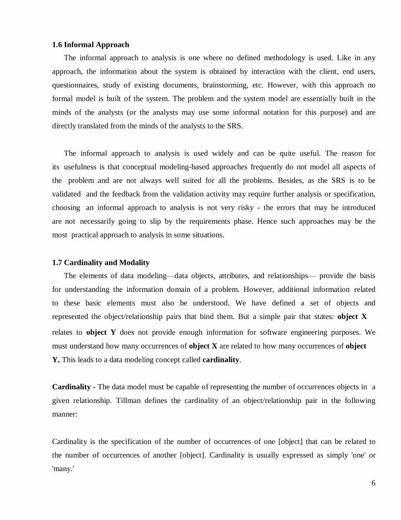
Modality- The modality of a relationship is 0 if there is no explicit need for the relationship
to occur or the relationship is optional. The modality is 1 if an occurrence of the
relationship is mandatory. To illustrate, consider software that is used by a local telephone
company to process requests for field service. A customer indicates that there is a problem. If the
problem is diagnosed as relatively simple, a single repair action occurs. However, if the
problem is complex, multiple repair actions may be required. Figure 12.5 illustrates the
relationship, cardinality, and modality between the data objects customer and repair action.
Fig: 2.2 Cardinality and Modality
8
1.8 Entity/Relationship Diagrams
The object/relationship pair is the cornerstone of the data model. These pairs can be represented
graphically using the entity/relationship diagram. The ERD was originally proposed by Peter Chen
for the design of relational database systems and has been extended by others. A set of primary
components are identified for the ERD: data objects, attributes, relationships, and various type
indicators. The primary purpose of the ERD is to represent data objects and their relationships.
Data objects are represented by a labeled rectangle. Relationships are indicated with a
labeled line connecting objects. In some variations of the ERD, the connecting line contains a
diamond that is labeled with the relationship. Connections between data objects and
relationships are established using a variety of special symbols that indicate cardinality and
modality.
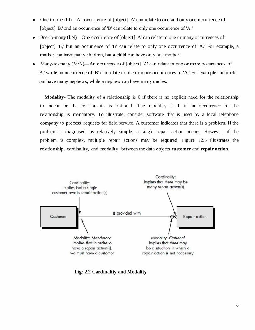
The relationship between the data objects car and manufacturer would be represented as
shown below. One manufacturer builds one or many cars.
By examining the symbols at the end of the connection line between objects, it can be seen
that the modality of both occurrences is mandatory (the vertical lines).
Expanding the model, we represent a grossly oversimplified ERD of the distribution element of
the automobile business. New data objects, shipper and dealership, are introduced. In addition,
new relationships—transports, contracts, licenses, and stocks—indicate how the data objects shown
in the figure associate with one another. Tables for each of the data objects contained in the
ERD would have to be developed according to the rules introduced earlier in this chapter.
ERD notation also provides a mechanism that represents the associatively between objects.
An associative data object is represented. In the figure, each of the data objects that model the
individual subsystems is associated with the data object car.
Fig: 2.3 ER diagram for car and manufacturer
9
1.9 Data Flow Modeling
Data-flow based modeling, often referred to as the structured analysis technique, uses function-
based decomposition while modeling the problem. It focuses on the functions performed in the
problem domain and the data consumed and produced by these functions. It is a top-down
refinement approach, which was originally called structured analysis and specification, and was
proposed for producing the specifications.
Data Flow Diagrams and Data Dictionary
Data flow diagrams (also called data flow graphs) are commonly used during problem
analysis. Data flow diagrams (DFDs) are quite general and are not limited to problem analysis for
software requirements specification. They were in use long before the software engineering discipline
began. DFDs are very useful in understanding a system and can be effectively used during
analysis.
A DFD shows the flow of data through a system. It views a system as a function that transforms
the inputs into desired outputs. Any complex system will not perform this transformation in a "single
step," and a data will typically undergo a series of transformations before it becomes the output.
The DFD aims to capture the transformations that take place within a system to the input data
so that eventually the output data is produced. The agent that performs the transformation of data from
one state to another is called a process (or a bubble). So, a DFD shows the movement of data
through the different transformations or processes in the system.
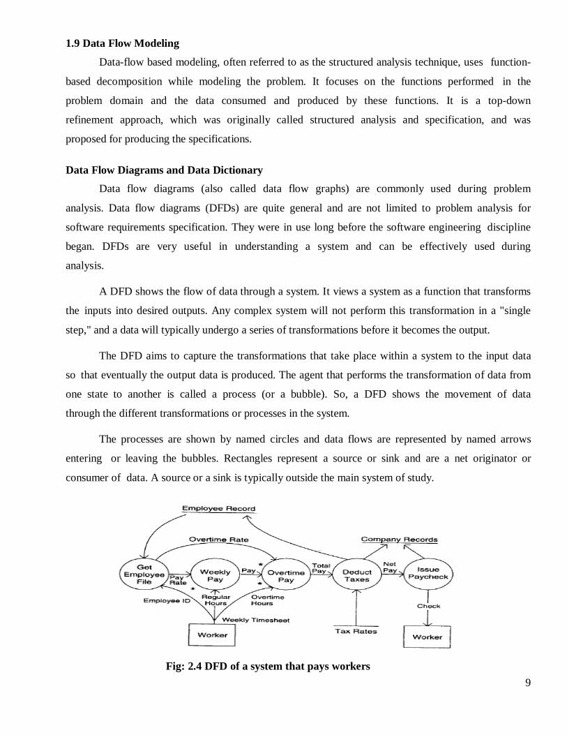
The processes are shown by named circles and data flows are represented by named arrows
entering or leaving the bubbles. Rectangles represent a source or sink and are a net originator or
consumer of data. A source or a sink is typically outside the main system of study.
Fig: 2.4 DFD of a system that pays workers
10
In this DFD there is one basic input data flow, the weekly timesheet, which originates from
the source worker. The basic output is the paycheck, the sink for which is also the worker. In this
system, first the employee's record is retrieved, using the employee ID, which is contained in the
timesheet. From the employee record, the rate of payment and overtime are obtained. These rates
and the regular and overtime hours (from the timesheet) are used to compute the pay. After the total
pay is determined, taxes are deducted. To compute the tax deduction, information from the tax-rate
file is used. The amount of tax deducted is recorded in the employee and company records. Finally, the
paycheck is issued for the net pay. The amount paid is also recorded in company records.
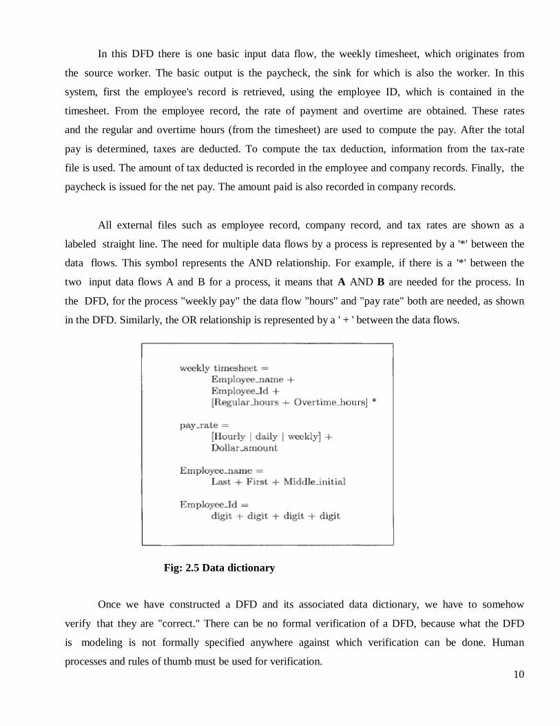
All external files such as employee record, company record, and tax rates are shown as a
labeled straight line. The need for multiple data flows by a process is represented by a '*' between the
data flows. This symbol represents the AND relationship. For example, if there is a '*' between the
two input data flows A and B for a process, it means that A AND B are needed for the process. In
the DFD, for the process "weekly pay" the data flow "hours" and "pay rate" both are needed, as shown
in the DFD. Similarly, the OR relationship is represented by a ' + ' between the data flows.
Fig: 2.5 Data dictionary
Once we have constructed a DFD and its associated data dictionary, we have to somehow
verify that they are "correct." There can be no formal verification of a DFD, because what the DFD
is modeling is not formally specified anywhere against which verification can be done. Human
processes and rules of thumb must be used for verification.
11
In addition to the walkthrough with the client, the analyst should look for common errors. Some
common errors:
Unlabeled data flows.
Missing data flows; information required by a process is not available.
Extraneous data flows; some information is not being used in the process.
Consistency not maintained during refinement.
Missing processes.
Contains some control information.
1.8 Object-Oriented Modeling
In object-oriented modeling, a system is viewed as a set of objects. The objects interact with
each other through the services they provide. Some objects also interact with the users through their
services such that the users get the desired services. Hence, the goal of modeling is to identify the
objects (actually the object classes) that exist in the problem domain, define the classes by specifying
what state information they encapsulate and what services they provide, and identify relationships
that exist between objects of different classes, such that the overall model is such that it supports the
desired user services.
Basic Concepts and Notation
In understanding or modeling a system using an object-oriented modeling technique, the
system is viewed as consisting of objects. Each object has certain attributes, which together define the
object. Separation of an object from its attributes is a natural method that we use for understanding
systems (a man is separate from his attributes of height, weight, etc.).
In object oriented systems, attributes hold the state (or define the state) of an object. An
attribute is a pure data value (like integer, string, etc.), not an object. Objects of similar type are
grouped together to form an object class (or just class). A class is essentially a type definition, which
defines the state space of objects of its type and the operations (and their semantics) that can be
applied to objects of that type. Formation of classes is also a general technique used by humans for
understanding systems and differentiating between classes (e.g., an apple tree is an instance of the
class of trees, and the class of trees is different from the class of birds).
Class diagrams represent a structure of the problem graphically using a precise notation. In a class
diagram, a class is represented as a portrait-style rectangle divided into three parts. The top part
contains the name of the class. The middle part lists the attributes that objects of this class possess.
12
And the third part lists the services provided by objects of this class.
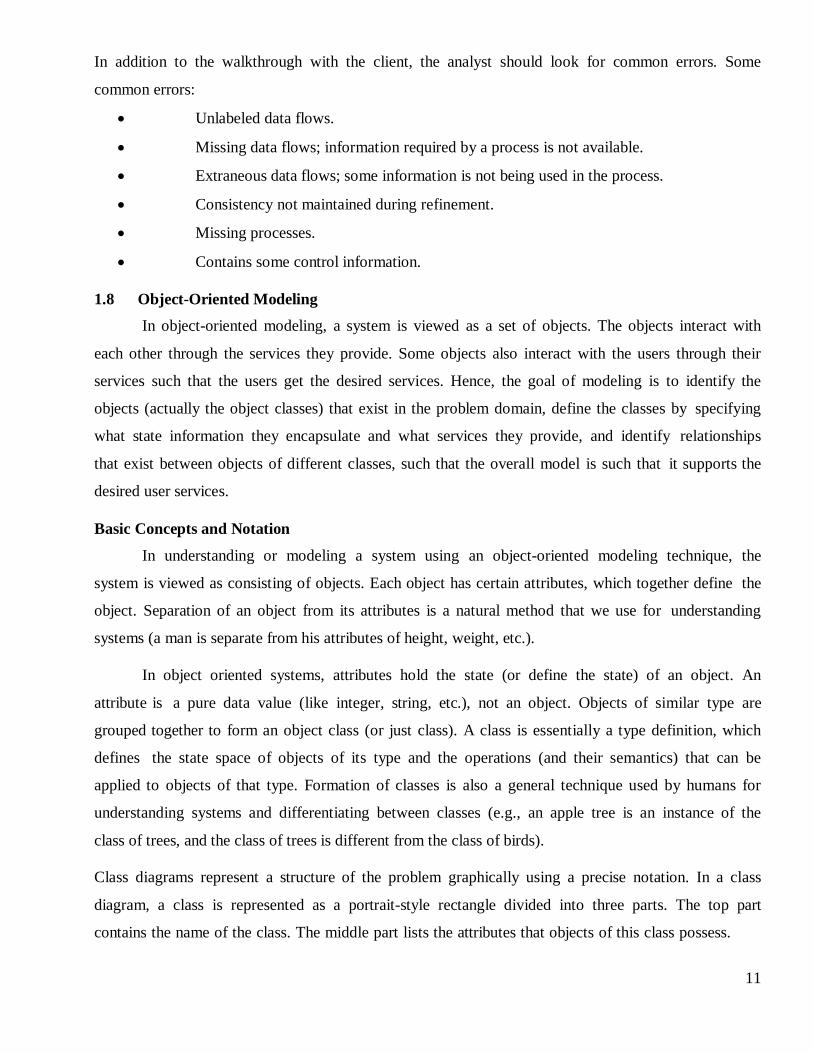
To model relationship between classes, a few structures are used. The generalization-
specialization structure can be used by a class to inherit all or some attributes and services of a
general class and add more attributes and services. This structure is modeled in object-oriented
modeling through inheritance. By using a general class and inheriting some of its attributes and
services and adding more, one can create a class that is a specialized version of the general class. And
many specialized classes can be created from a general class, giving us class hierarchies. The
aggregation structure models the whole-part relationship. An object may be composed of many
objects; this is modeled through the aggregation structure.
Generalization -specialization structure aggregation structure
Fig: 2.6 Class structures
Performing Analysis:
Identifying objects and classes.
Identifying structures.
Identifying attributes.
Identifying associations.
Defining services.
Identifying Objects and Classes
An object during analysis is an encapsulation of attributes on which it provides some
exclusive services. It represents something in the problem space. It has been argued that though
things like interfaces between components, functions, etc. are generally volatile and change with
changing needs, objects are quite stable in a problem domain.
13
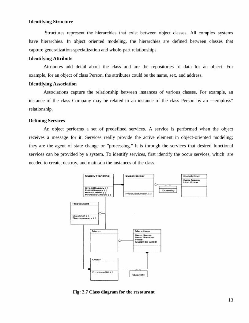
Identifying Structure
Structures represent the hierarchies that exist between object classes. All complex systems
have hierarchies. In object oriented modeling, the hierarchies are defined between classes that
capture generalization-specialization and whole-part relationships.
Identifying Attribute
Attributes add detail about the class and are the repositories of data for an object. For
example, for an object of class Person, the attributes could be the name, sex, and address.
Identifying Association
Associations capture the relationship between instances of various classes. For example, an
instance of the class Company may be related to an instance of the class Person by an ―employs"
relationship.
Defining Services
An object performs a set of predefined services. A service is performed when the object
receives a message for it. Services really provide the active element in object-oriented modeling;
they are the agent of state change or "processing." It is through the services that desired functional
services can be provided by a system. To identify services, first identify the occur services, which are
needed to create, destroy, and maintain the instances of the class.
Fig: 2.7 Class diagram for the restaurant
14
1.9 Prototyping
Prototyping takes a different approach to problem analysis as compared to modeling-based
approaches. In prototyping, a partial system is constructed, which is then used by the client, users,
and developers to gain a better understanding of the problem and the needs. Hence, actual experience
with a prototype that implements part of the eventual software system is used to analyze the problem
and understand the requirements for the eventual software system. A software prototype can be
defined as a partial implementation of a system whose purpose is to learn something about the
problem being solved or the solution approach. As stated in this definition, prototyping can also be
used to evaluate or check a design alternative (such a prototype is called a design prototype).
There are two approaches to prototyping:
Throwaway
Evolutionary.
In the throwaway approach the prototype is constructed with the idea that it will be discarded
after the analysis is complete and the final system will be built from scratch. In the evolutionary
approach, the prototype is built with the idea that it will eventually be converted into the final
system. From the point of view of problem analysis and understanding, the throwaway prototypes are
more suited.
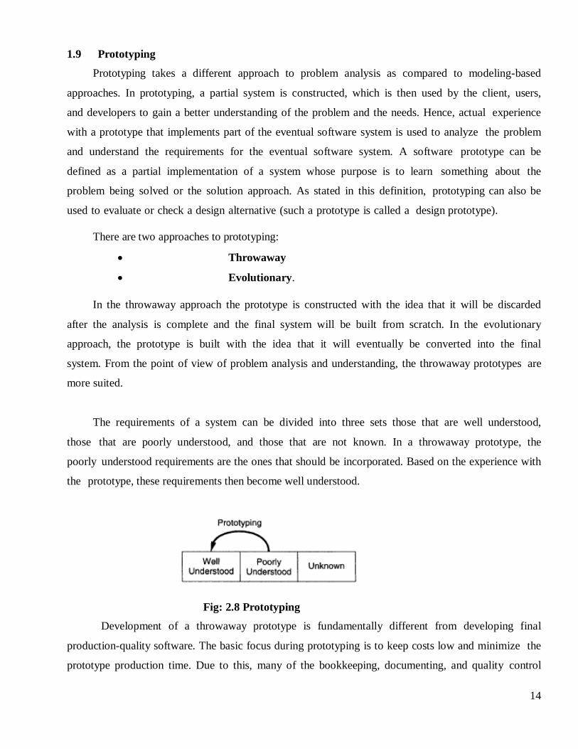
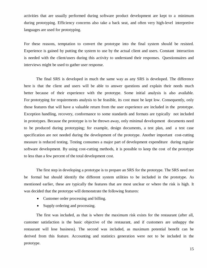
The requirements of a system can be divided into three sets those that are well understood,
those that are poorly understood, and those that are not known. In a throwaway prototype, the
poorly understood requirements are the ones that should be incorporated. Based on the experience with
the prototype, these requirements then become well understood.
Fig: 2.8 Prototyping
Development of a throwaway prototype is fundamentally different from developing final
production-quality software. The basic focus during prototyping is to keep costs low and minimize the
prototype production time. Due to this, many of the bookkeeping, documenting, and quality control
15
activities that are usually performed during software product development are kept to a minimum
during prototyping. Efficiency concerns also take a back seat, and often very high-level interpretive
languages are used for prototyping.
For these reasons, temptation to convert the prototype into the final system should be resisted.
Experience is gained by putting the system to use by the actual client and users. Constant interaction
is needed with the client/users during this activity to understand their responses. Questionnaires and
interviews might be used to gather user response.
The final SRS is developed in much the same way as any SRS is developed. The difference
here is that the client and users will be able to answer questions and explain their needs much
better because of their experience with the prototype. Some initial analysis is also available.
For prototyping for requirements analysis to be feasible, its cost must be kept low. Consequently, only
those features that will have a valuable return from the user experience are included in the prototype.
Exception handling, recovery, conformance to some standards and formats are typically not included
in prototypes. Because the prototype is to be thrown away, only minimal development documents need
to be produced during prototyping; for example, design documents, a test plan, and a test case
specification are not needed during the development of the prototype. Another important cost-cutting
measure is reduced testing. Testing consumes a major part of development expenditure during regular
software development. By using cost-cutting methods, it is possible to keep the cost of the prototype
to less than a few percent of the total development cost.
The first step in developing a prototype is to prepare an SRS for the prototype. The SRS need not
be formal but should identify the different system utilities to be included in the prototype. As
mentioned earlier, these are typically the features that are most unclear or where the risk is high. It
was decided that the prototype will demonstrate the following features:
Customer order processing and billing.
Supply ordering and processing.
The first was included, as that is where the maximum risk exists for the restaurant (after all,
customer satisfaction is the basic objective of the restaurant, and if customers are unhappy the
restaurant will lose business). The second was included, as maximum potential benefit can be
derived from this feature. Accounting and statistics generation were not to be included in the
prototype.
16
The prototype was developed using a database system, in which good facilities for data entry
and form (bill) generation exist. The user interface for the waiters and the restaurant manager
was included in the prototype. The system was used, in parallel with the existing system, for a
few weeks, and informal surveys with the customers were conducted. Customers were generally
pleased with the accuracy of the bills and the details they provided. Some gave suggestions about
the bill layout. Based on the experience of the waiters, the codes for the different menu items were
modified to an alphanumeric code. They found that the numeric codes used in the prototype were
hard to remember. The experience of the restaurant manager and feedback from the supply were
used to determine the final details about supply processing and handling.
1.10 Requirements Specification
The final output is the software requirements specification document (SRS. An analyst
typically will analyze some parts of the problem and then write the requirements for that part.
Problem analysis and requirements specification activities overlap, with movement from both activities
to the other. Some suggest that a ―standard template‖ should be developed and used for a system
specification, arguing that this leads to requirements that are presented in a consistent and therefore
more understandable manner. For large systems, a written document, combining natural language
descriptions and graphical models may be the best approach, However, usage scenarios may be all
that are required for smaller products or systems that reside within well-understood technical
environments.
The system specification is the final work product produced by the system and requirements
engineer. It serves as the foundation for hardware engineering, software engineering, database
engineering and human engineering. It describes the function performance of a computer based
system and the constraints that will govern its development. The specification bounds each allocated
system element. The system specification also describes the information that is input to and output
from the system.
1.11 Characteristics of an SRS
To properly satisfy the basic goals, an SRS should have certain properties and should contain
different types of requirements:
Correct.
Complete.
Unambiguous.
17
Verifiable.
Consistent.
Ranked for importance and/or stability.
Modifiable.
Traceable.
An SRS is correct if every requirement included in the SRS represents something required in
the final system. An SRS is complete if everything the software is supposed to do and the responses of
the software to all classes of input data are specified in the SRS.
Correctness and completeness go hand-in-hand; whereas correctness ensures that which is
specified is done correctly, completeness ensures that everything is indeed specified. Correctness is an
easier property to establish than completeness as it basically involves examining each requirement
to make sure it represents the user requirement. Completeness, on the other hand, is the most difficult
property to establish.
An SRS is unambiguous if and only if every requirement stated has one and only one
interpretation. Requirements are often written in natural language, which are inherently ambiguous. If
the requirements are specified in a natural language, the SRS writer has to be especially careful to
ensure that there are no ambiguities.
An SRS is verifiable if and only if every stated requirement is verifiable. A requirement is
verifiable if there exists some cost-effective process that can check whether the final software meets
that requirement. This implies that the requirements should have as little subjectivity as possible
because subjective requirements are difficult to verify. Unambiguity is essential for verifiability.
An SRS is consistent if there is no requirement that conflicts with another. Terminology can
cause inconsistencies; for example, different requirements may use different terms to refer to the
same object.
For example, suppose a requirement states that an event e is to occur before another event. But
then another set of requirements states (directly or indirectly by transitivity) that event / should
occur before event e. Inconsistencies in an SRS can reflect of some major problems.
An SRS is ranked for importance and/or stability if for each requirement the importance and
the stability of the requirement are indicated. Stability of a requirement reflects the chances of it
changing in future. It can be reflected in terms of the expected change volume. Writing an SRS is
an iterative process. Even when the requirements of a system are specified, they are later modified as
18
the needs of the client change. Hence an SRS should be easy to modify.
An SRS is modifiable if its structure and style are such that any necessary change can be
made easily while preserving completeness and consistency. Presence of redundancy is a major
hindrance to modifiability, as it can easily lead to errors. For example, assume that a requirement is
stated in two places and that the requirement later needs to be changed. If only one occurrence
of the requirement is modified, the resulting SRS will be inconsistent.
An SRS is traceable if the origin of each of its requirements is clear and if it facilitates
the referencing of each requirement in future development. Forward traceability means that each
requirement should be traceable to some design and code elements. Backward traceability requires
that it be possible to trace design and code elements to the requirements they support. Traceability
aids verification and validation.
1.12 Components of an SRS.
Functionality.
Performance.
Design constraints imposed on an implementation.
External interfaces.
Functional Requirements:
Functional requirements specify which outputs should be produced from the given inputs.
They describe the relationship between the input and output of the system. For each functional
requirement, a detailed description of all the data inputs and their source, the units of measure, and the
range of valid inputs must be specified.
All the operations to be performed on the input data to obtain the output should be specified.
This includes specifying the validity checks on the input and output data, parameters affected by
the operation, and equations or other logical operations that must be used to transform the inputs into
corresponding outputs. For example, if there is a formula for computing the output, it should be
specified. Care must be taken not to specify any algorithms that are not part of the system but that
may be needed to implement the system. These decisions should be left for the designer.
An example of this situation is an airline reservation system, where a reservation cannot be made
even for valid passengers if the airplane is fully booked. In short, the system behavior for all foreseen
inputs and all foreseen system states should be specified. These special conditions are often likely to be
overlooked, resulting in a system that is not robust.
19
Performance Requirements:
This part of an SRS specifies the performance constraints on the software system. All the
requirements relating to the performance characteristics of the system must be clearly specified.
There are two types of performance requirements: static and dynamic.
Static requirements are those that do not impose constraint on the execution characteristics of the
system. These include requirements like the number of terminals to be supported, the number of
simultaneous users to be supported, and the number of files that the system has to process and their
sizes. These are also called capacity requirements of the system.
Dynamic requirements specify constraints on the execution behavior of the system. These typically
include response time and throughput constraints on the system. Response time is the expected time for
the completion of an operation under specified circumstances. Throughput is the expected
number of operations that can be performed in a unit time.
For example, the SRS may specify the number of transactions that must be processed per unit time, or
what the response time for a particular command should be. Acceptable ranges of the different
performance parameters should be specified, as well as acceptable performance for both normal and
peak workload conditions.
Design Constraints:
There are a number of factors in the client's environment that may restrict the choices of a
designer.
Standards Compliance:
This specifies the requirements for the standards the system must follow. The standards may
include the report format and accounting procedures. There may be audit tracing requirements,
which require certain kinds of changes, or operations that must be recorded in an audit file.
Hardware Limitations:
The software may have to operate on some existing or predetermined hardware, thus imposing
restrictions on the design. Hardware limitations can include the type of machines to be used,
operating system available on the system, languages supported, and limits on primary and
secondary storage.
Reliability and Fault Tolerance:
Fault tolerance requirements can place a major constraint on how the system is to be
20
designed. Fault tolerance requirements often make the system more complex and expensive.
Requirements about system behavior in the face of certain kinds of faults are specified. Recovery
requirements are often an integral part here, detailing what the system should do if some failure
occurs to ensure certain properties. Reliability requirements are very important for critical
applications.
Security:
Security requirements are particularly significant in defense systems and many database
systems. Security requirements place restrictions on the use of certain commands, control access to
data, provide different kinds of access requirements for different people, require the use of passwords
and cryptography techniques, and maintain a log of activities in the system.
External Interface Requirements:
All the interactions of the software with people, hardware, and other software should be
clearly specified. For the user interface, the characteristics of each user interface of the software
product should be specified. User interface is becoming increasingly important and must be given
proper attention. For hardware interface requirements, the SRS should specify the logical
characteristics of each interface between the software product and the hardware components.
1.13 Specification.
Requirements specification necessitates the use of some specification language. The
language should support the desired qualities of the SRS modifiability, understandability,
unambiguous, and so forth. In addition, the language should be easy to learn and use. For example, to
avoid ambiguity, it is best to use some formal language. But for ease of understanding a natural
language might be preferable.
The major advantage of using a natural language is that both client and supplier understand the
language. However, by the very nature of a natural language, it is imprecise and ambiguous. To
reduce the drawbacks of natural languages, most often natural language is used in a structured
fashion. In structured English (for example), requirements are broken into sections and paragraphs.
Each paragraph is then broken into subparagraphs. Many organizations also specify strict uses of
some words like "shall," "perhaps," and "should" and try to restrict the use of common phrases in
order to improve the precision and reduce the verbosity and ambiguity.
In an SRS, some parts can be specified better using some formal notation. For example, to specify
formats of inputs or outputs, regular expressions can be very useful. Similarly, when discussing
21
systems like communication protocols, finite state automata can be used. Decision tables are useful to
formally specify the behavior of a system on different combinations of inputs or settings.
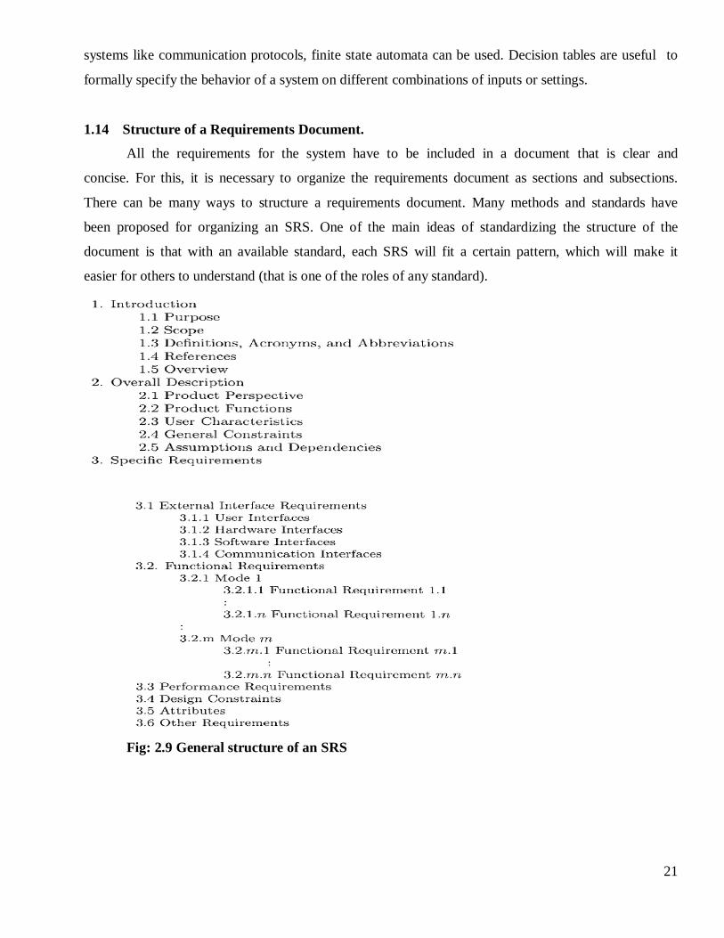
1.14 Structure of a Requirements Document.
All the requirements for the system have to be included in a document that is clear and
concise. For this, it is necessary to organize the requirements document as sections and subsections.
There can be many ways to structure a requirements document. Many methods and standards have
been proposed for organizing an SRS. One of the main ideas of standardizing the structure of the
document is that with an available standard, each SRS will fit a certain pattern, which will make it
easier for others to understand (that is one of the roles of any standard).
Fig: 2.9 General structure of an SRS
22
1.15 Functional Specification with Use Cases.
Functional requirements often form the core of a requirements document. The traditional
approach for specifying functionality is to specify each function that the system should
provide. Use cases specify the functionality of a system by specifying the behavior of the
system, captured as interactions of the users with the system. Use cases can be used to
describe the business processes of the larger business or organization that deploys the
software or it could just describe the behavior of the software system.
Basics:
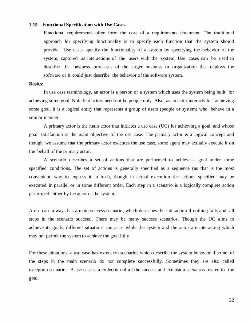
In use case terminology, an actor is a person or a system which uses the system being built for
achieving some goal. Note that actors need not be people only. Also, as an actor interacts for achieving
some goal, it is a logical entity that represents a group of users (people or system) who behave in a
similar manner.
A primary actor is the main actor that initiates a use case (UC) for achieving a goal, and whose
goal satisfaction is the main objective of the use case. The primary actor is a logical concept and
though we assume that the primary actor executes the use case, some agent may actually execute it on
the behalf of the primary actor.
A scenario describes a set of actions that are performed to achieve a goal under some
specified conditions. The set of actions is generally specified as a sequence (as that is the most
convenient way to express it in text), though in actual execution the actions specified may be
executed in parallel or in some different order. Each step in a scenario is a logically complete action
performed either by the actor or the system.
A use case always has a main success scenario, which describes the interaction if nothing fails and all
steps in the scenario succeed. There may be many success scenarios. Though the UC aims to
achieve its goals, different situations can arise while the system and the actor are interacting which
may not permit the system to achieve the goal fully.
For these situations, a use case has extension scenarios which describe the system behavior if some of
the steps in the main scenario do not complete successfully. Sometimes they are also called
exception scenarios. A use case is a collection of all the success and extension scenarios related to the
goal.
23
Use Case terms:
Fig: 2.10 Use Case terms
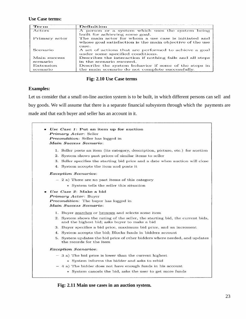
Examples:
Let us consider that a small on-line auction system is to be built, in which different persons can sell and
buy goods. We will assume that there is a separate financial subsystem through which the payments are
made and that each buyer and seller has an account in it.
Fig: 2.11 Main use cases in an auction system.
24
1.16 Extensions.
Besides specifying the primary actor, its goal and the success and exceptional scenarios, a use
case can also specify a scope. If the system being built has many subsystems, as is often the case,
sometimes system use cases may actually be capturing the behavior of some system. In such a situation
it is better to specify the scope of that use case as the subsystem.
Use case 0 : Auction an item.
Primary Actor : Auction System.
Scope : Auction conducting organization.
Precondition : None.
Main success scenario:
Seller performs Put an item for auction.
Various bidders perform make a bid.
On final date perform complete the auction of the item.
Get feedback from seller; get feedback from buyer; update records.
1.17 Developing Use Cases.
UCs not only document requirements, as their form is like storytelling and uses text, both of
which are easy and natural with different stakeholders, they also are a good medium for discussion
and brainstorming. Hence, UCs can also be used for requirements elicitation and problem analysis.
While developing use cases, informal or formal models may also be built, though they are not
required.
Actors and goals:
The actor-goal list enumerates the use cases and specifies the actors for each goal. (The
name of the use case is generally the goal.) This table may be extended by giving a brief description of
each of the use cases. At this level, the use cases specify the scope of the system and give an
overall view of what it does. Completeness of functionality can be assessed fairly well by reviewing
these.
Main success scenarios:
For each of the use cases, the main success scenarios are provided at this level. With the
main scenarios, the system behavior for each use case is specified. This description can be reviewed to
ensure that interests of all the stakeholders are met and that the use case is delivering the desired
behavior.
25
Failure conditions:
Once the success scenario is listed, all the possible failure conditions can be identified. At
this level, for each step in the main success scenario, the different ways in which a step can fail
form the failure conditions. Before deciding what should be done in these failure conditions (which is
done at the next level), it is better to enumerate the failure conditions and reviewed for completeness.
Failure handling:
This is perhaps the most tricky and difficult part of writing a use case. Often the focus is so
much on the main functionality that people do not pay attention to how failures should be handled.
Determining what should be the behavior under different failure conditions will often identify new
business rules or new actors.
1.18 Requirements analysis and negotiation.
Once requirements have been gathered, the work products noted earlier form the basis for
requirements analysis.
As the requirements analysis activity commences, the following questions are asked and answered:
Is each requirement consistent with the overall objective for the system/product?
Have all requirements been specified at the proper level of abstraction?
Is the requirement really necessary or does it represent an add-on feature that may not be
essential to the objective of the system?
Is each requirement bounded and unambiguous?
Does each requirement have attribution? That is, is a source (generally, a specific
individual) noted for each requirement?
Do any requirements conflict with other requirements?
Is each requirement achievable in the technical environment that will house the system or
product?
Is each requirement testable, once implemented?
1.19 Requirements Validation.
The work products produced as a consequence of requirements engineering (a system
specification and related information) are assessed for quality during a validation step. Requirements
validation examines the specification to ensure that all system requirements have been stated
unambiguously; that inconsistencies, omissions, and errors have been detected and corrected; and
that the work products conform to the standards established for the process, the project, and the
product.
26
The following questions represent a small subset of those that might be asked:
Are requirements stated clearly? Can they be misinterpreted?
Is the source (e.g., a person, a regulation, a document) of the requirement identified?
Is the requirement bounded in quantitative terms?
What other requirements relate to this requirement?
Does the requirement violate any domain constraints?
Is the requirement testable?
Is the requirement traceable to any system model that has been created?
Is the requirement traceable to overall system/product objectives?
1.20 Requirements Management.
Requirements management is a set of activities that help the project team to identify, control,
and track requirements and changes to requirements at any time as the project proceeds.
Each requirement is assigned a unique identifier that might take the form
<requirement type><requirement #>
where requirement type takes on values such as F = functional requirement, D = data requirement, B
= behavioral requirement, I = interface requirement, and P = output requirement. Hence, a
requirement identified as F09 indicates a functional requirement assigned requirement number 9.
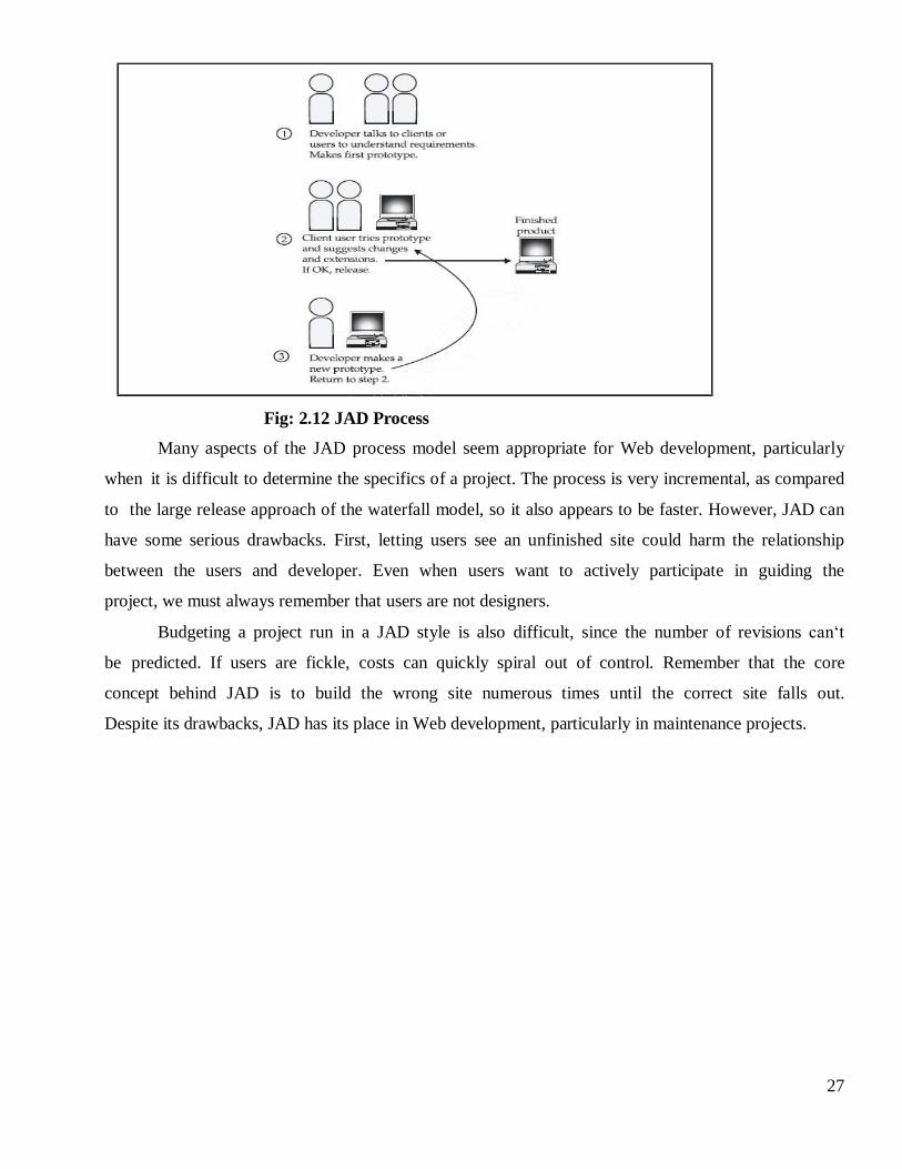
1.21 Joint Application Development (JAD or Evolutionary Prototyping).
It involves evolving a prototype site to its final form in a series of steps. A prototype is built
and shown to the client or potentially the end user. The concerned party then provides direct
feedback that is used to guide the next version of the prototype, and so on until the final form is
developed.
27
Fig: 2.12 JAD Process
Many aspects of the JAD process model seem appropriate for Web development, particularly
when it is difficult to determine the specifics of a project. The process is very incremental, as compared
to the large release approach of the waterfall model, so it also appears to be faster. However, JAD can
have some serious drawbacks. First, letting users see an unfinished site could harm the relationship
between the users and developer. Even when users want to actively participate in guiding the
project, we must always remember that users are not designers.
Budgeting a project run in a JAD style is also difficult, since the number of revisions can‘t
be predicted. If users are fickle, costs can quickly spiral out of control. Remember that the core
concept behind JAD is to build the wrong site numerous times until the correct site falls out.
Despite its drawbacks, JAD has its place in Web development, particularly in maintenance projects.