t600mep-2 programmable economizer …cgproducts.johnsoncontrols.com/met_pdf/249889150.pdft600mep-2...
TRANSCRIPT
Installation Instructions Issue Date January 19, 2005
© 2005 Johnson Controls, Inc. 1
T600MEP-2 Programmable Economizer Thermostat
Application The T600MEP-2 is a programmable thermostat for control of single- or two-stage unitary rooftop units with economizers. The T600MEP-2 thermostat provides exceptional accuracy through the use of a unique Proportional-Integral (PI) time proportioning algorithm. The algorithm virtually eliminates temperature offset associated with traditional, differential-based on/off thermostats. The T600MEP-2 also uses an adaptive control logic algorithm to control the space temperature during recovery to minimize overshoot while providing maximum comfort. Economizer functions include a 0 to 10 VDC control signal, dry bulb changeover strategy, adjustable minimum position, and mixed air setpoint control. Additionally, the menu driven backlit display, plain text menus, and five keys on the T600MEP-2 make programming the thermostat easy and intuitive.
Installation Location Considerations Locate the T600MEP-2 thermostat:
• on a partitioning interior wall, and approximately 5 ft. (1.5 m) above the floor in a location of average temperature
• away from direct sunlight, radiant heat, outside walls, behind doors, air discharge grills, stairwells, or outside doors
• away from steam or water pipes, warm air stacks, unheated/uncooled areas, or sources of electrical interference
To install the thermostat:
1. Remove the security screw on the bottom of the thermostat cover using a Phillips-head screwdriver. Open the thermostat by pulling on the bottom side of the thermostat cover (Figure 1).
2. Unlock the Printed Circuit Board (PCB) by carefully pressing the locking tabs to the right (Figure 2). Open the thermostat’s PCB to the left.
3. Pull out approximately 6 in. (152 mm) of wires from the wall and insert the cable through the hole in the base.
4. Align the base on the wall, and using the base as a template, mark the location of the two mounting holes on the wall. Confirm the thermostat base is installed with the proper side up.
5. Use the supplied anchors and screws for mounting on drywall or plaster. Drill two 3/16 in. (4.7 mm) holes at the marked locations and tap nylon anchors flush to wall surface (Figure 3).
6. Position base on the wall, insert screws through mounting base, and fasten into wall anchors. Do not overtighten screws.
7. Swing the thermostat PCB back to the right to close. Gently press on the PCB to secure each of the locking tabs.
8. Pull out the screw terminal blocks using the pull-tabs on each connector (Figure 4).
Note: The number of terminals on the terminal blocks varies depending on the T600 model.
IMPORTANT: Use this T600MEP-2 programmable economizer thermostat only as an operating control. Where failure or malfunction of the thermostat could lead to personal injury or property damage to the controlled equipment or other property, additional precautions must be designed into the system. Incorporate and maintain other devices such as supervisory or alarm systems or safety or limit controls intended to warn of, or protect against, failure or malfunction of the thermostat.
Part No. 24-9889-150, Rev. A www.johnsoncontrols.com

T600
_TEC
_Rem
ove_
Cov
er
Figure 1: Removing the Thermostat Cover
PCBLocking Tabs
T600
_TEC
_Ope
nm_S
tat
Figure 2: Opening the Thermostat PCB
T600
_TEC
_Mou
ntin
g_Ba
se
Figure 3: Mounting the Thermostat Base
T600
_TEC
_Ter
min
al_B
lock
s
Figure 4: Removing the Terminal Blocks
Wiring
! CAUTION: Risk of Electric Shock. Disconnect power supply before making electrical connections to avoid electric shock.
Note: When replacing an existing thermostat, remove and label wires to identify terminal designations. When replacing a T600MEP thermostat, simply remove the terminal blocks and reinsert on to the new thermostat.
To wire the thermostat:
1. Strip each wire 1/4 in. (6.35 mm) and connect to the appropriate terminal according to the wiring diagram (see Figure 5).
2. Gently push excess wire back into wall, plug the wall hole with fireproof material to prevent drafts from affecting ambient temperature readings, and install screw terminal blocks back onto the PCB.
3. Reattach the thermostat cover to the installed base (top side first) and install the security screw on the bottom.
! CAUTION: Risk of Property Damage. Do not apply power to the system before checking all wiring connections. Short circuited or improperly connected wires may result in permanent damage to the equipment.
2 T600MEP-2 Programmable Economizer Thermostat Installation Instructions

Y2 Y1 G RC C RH W1 W2
D1 D2 RS Scom
5 pole left top connector 3 pole right topconnector
8 pole bottom connector
Cool 2
24 VACThermostat Power
Y2 Y1 G RC C
If using the same power sourcefor the thermostat and heating loads, install a jumperacross RC and RH.
Heat 1 Heat 2
RH W1 W2
FanCool 1
Energizes on a call for first stage coolingEnergizes on a call for second stage coolingEnergizes fan in accordance with the selected fan mode24 VAC from equipment transformer24 VAC (common) from equipment transformer24 VAC for heating stagesEnergizes on a call for first stage heatingEnergizes on a call for second stage heatingConfigurable auxiliary outputConfigurable digital inputConfigurable digital inputRemote room sensorSensor commonOutdoor air sensorMixed air sensor0 - 10 VDC Economizer actuator output
FunctionY1Y2G
RCC
RHW1W2
AUXD1D2RS
ScomOSMSEC
Terminal
OS
D2 ScomRSD1
RemoteRoomSensor
OS
RemoteOutdoorSensor
EC
0 to
10
VDC
24 V
ACC
omm
onAux
AUX
MSEC AUX
RemoteMixed AirSensor
Cool 2
T600
MEP
_Wiri
ng
Figure 5: T600MEP-2 Thermostat Wiring Schematic
T600MEP-2 Programmable Economizer Thermostat Installation Instructions 3

Setup and Adjustments Thermostat Operation Overview
75.0ºFBacklit, plain text, LiquidCrystal Display (LCD)is easy to read in anycondition.
Five keys on the T600make operation easyand intuitive.
Light Emitting Diodes (LEDs)indicate system activity.
Room Temp
T600
_TEC
_Fro
nt_C
over
Figure 6: T600MEP-2 Thermostat Front Cover
Thermostat Interface Keys The T600MEP-2 interface consists of five keys on the front cover and one configuration key (Figure 7) that are accessed by removing the front cover. Use the: • YES/SCROLL key to:
− confirm menu selections, and to advance to the next menu item
− stop the Status Display Menu from scrolling and to manually scroll to the next parameter on the menu. When left unattended for 45 seconds, the display resumes scrolling.
• NO key when you do not desire a parameter change, and to advance to the next menu item
• MENU key to access the Main User Menu or exit the menu
• UP/DOWN arrow keys to:
− adjust values
− activate a Temporary Setpoint
Backlit Liquid Crystal Display (LCD) The T600MEP-2 uses a two-line, eight-character display. Low-level backlighting is present during normal operation, and it brightens when any user interface key is pressed. The backlight returns to the lower level when the thermostat is left unattended for 45 seconds.
ConfigurationKey T6
00_T
EC_C
onfig
_Key
Figure 7: Configuration Key Location
Light-Emitting Diodes (LEDs) Three LEDs are used to indicate the status of the fan, call for heat, or call for cooling. When: • the fan is on, the FAN LED lights up
• heating is on, the HEAT LED lights up
• cooling is on, the COOL LED lights up
Programming Overview There are three menus used to view, program, and configure the T600MEP-2 thermostat: Status Display, Main User, and Installer Configuration Menus.
The Status Display Menu is displayed during normal thermostat operation. The menu continually scrolls through the following parameters:
• Room Temperature
• Day and Time
• System Mode
• Schedule Status (Occupied/Unoccupied)
4 T600MEP-2 Programmable Economizer Thermostat Installation Instructions
• Outdoor Temperature (providing sensor is connected and functional)
• Applicable Alarms (The backlight lights up and an alarm condition is displayed.)
To temporarily stop the scrolling, press the YES/SCROLL key.
The Main User Menu is used to access and change the thermostat’s basic operating parameters. Access the menu by pressing the MENU key during normal thermostat operation.
The Installer Configuration Menu is used to set up the thermostat for application specific operation. Access the menu by removing the front cover and pressing the configuration key, labeled CONFIG (Figure 7).
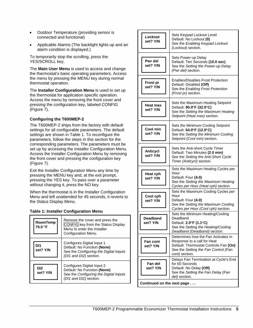
Configuring the T600MEP-2 The T600MEP-2 ships from the factory with default settings for all configurable parameters. The default settings are shown in Table 1. To reconfigure the parameters, follow the steps in this section for the corresponding parameters. The parameters must be set up by accessing the Installer Configuration Menu. Access the Installer Configuration Menu by removing the front cover and pressing the configuration key (Figure 7).
Exit the Installer Configuration Menu any time by pressing the MENU key and, at the exit prompt, pressing the YES key. To pass over a parameter without changing it, press the NO key.
When the thermostat is in the Installer Configuration Menu and left unattended for 45 seconds, it reverts to the Status Display Menu.
Table 1: Installer Configuration Menu Remove the cover and press the
CONFIG key from the Status Display Menu to enter the Installer Configuration Menu.
Configures Digital Input 1 Default: No Function (None) See the Configuring the Digital Inputs (DI1 and DI2) section.
Configures Digital Input 2 Default: No Function (None) See the Configuring the Digital Inputs (DI1 and DI2) section.
Sets Keypad Lockout Level Default: No Lockout (0) See the Enabling Keypad Lockout (Lockout) section.
Sets Power-up Delay Default: Ten Seconds (10.0 sec) See the Setting the Power-up Delay (Pwr del) section.
Enables/Disables Frost Protection Default: Disabled (Off) See the Enabling Frost Protection (Frost pr) section.
Sets the Maximum Heating Setpoint Default: 90.0°F (32.0°C) See the Setting the Maximum Heating Setpoint (Heat max) section.
Sets the Minimum Cooling Setpoint Default: 54.0°F (12.0°C) See the Setting the Minimum Cooling Setpoint (Cool min) section.
Sets the Anti-short Cycle Timer Default: Two Minutes (2.0 min) See the Setting the Anti-Short Cycle Timer (Anticycl) section.
Sets the Maximum Heating Cycles per Hour Default: Four (4.0) See the Setting the Maximum Heating Cycles per Hour (Heat cph) section.
Sets the Maximum Cooling Cycles per Hour Default: Four (4.0) See the Setting the Maximum Cooling Cycles per Hour (Cool cph) section.
Sets the Minimum Heating/Cooling Deadband Default: 2.0°F (1.1°C) See the Setting the Heating/Cooling Deadband (Deadband) section.
Determines how the Fan Activates in Response to a call for Heat Default: Thermostat Controls Fan (On)See the Setting the Fan Control (Fan cont) section.
Delays Fan Termination at Cycle’s End for 60 Seconds Default: No Delay (Off) See the Setting the Fan Delay (Fan del) section.
Continued on the next page . . .
Lockoutset? Y/N
Pwr delset? Y/N
Frost prset? Y/N
Heat maxset? Y/N
Cool minset? Y/N
Anticyclset? Y/N
Heat cphset? Y/N
Cool cphset? Y/N
Deadbandset? Y/N RoomTemp
75.0 °F
Fan contset? Y/N DI1
set? Y/N
Fan delset? Y/NDI2
set? Y/N
T600MEP-2 Programmable Economizer Thermostat Installation Instructions 5
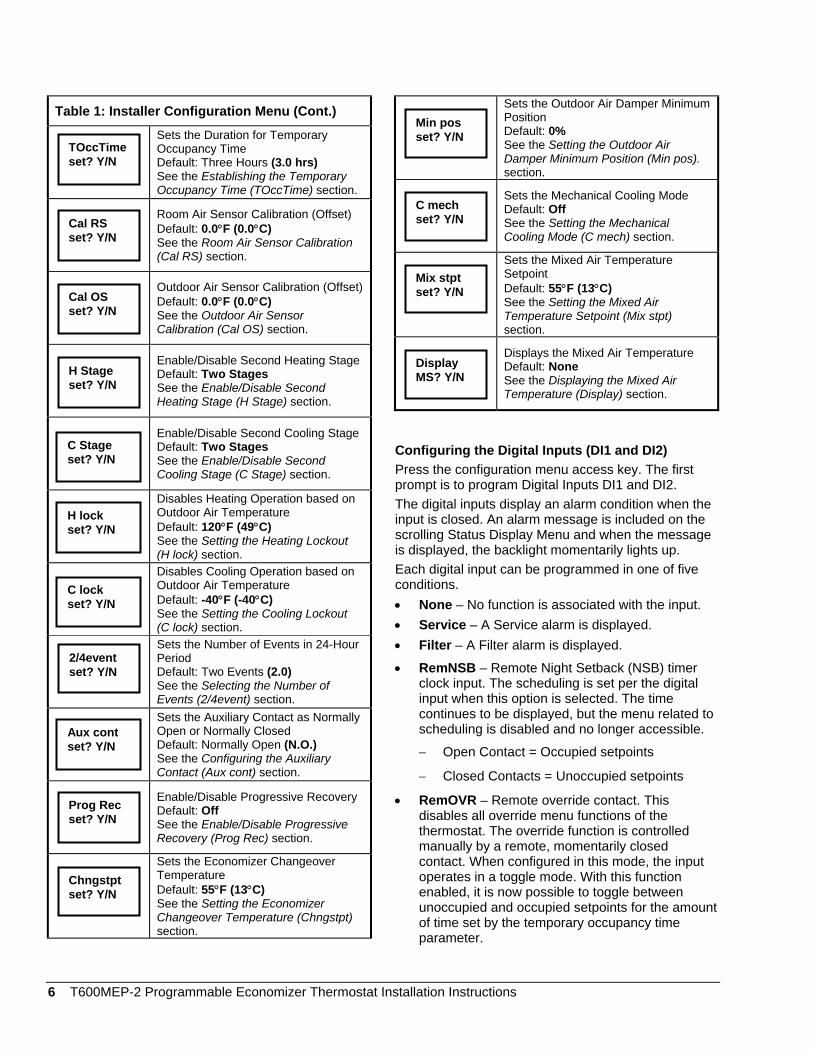
Table 1: Installer Configuration Menu (Cont.) Sets the Duration for Temporary
Occupancy Time Default: Three Hours (3.0 hrs) See the Establishing the Temporary Occupancy Time (TOccTime) section.
Room Air Sensor Calibration (Offset) Default: 0.0°F (0.0°C) See the Room Air Sensor Calibration (Cal RS) section.
Outdoor Air Sensor Calibration (Offset)Default: 0.0°F (0.0°C) See the Outdoor Air Sensor Calibration (Cal OS) section.
Enable/Disable Second Heating StageDefault: Two Stages See the Enable/Disable Second Heating Stage (H Stage) section.
Enable/Disable Second Cooling StageDefault: Two Stages See the Enable/Disable Second Cooling Stage (C Stage) section.
Disables Heating Operation based on Outdoor Air Temperature Default: 120°F (49°C) See the Setting the Heating Lockout (H lock) section.
Disables Cooling Operation based on Outdoor Air Temperature Default: -40°F (-40°C) See the Setting the Cooling Lockout (C lock) section.
Sets the Number of Events in 24-Hour Period Default: Two Events (2.0) See the Selecting the Number of Events (2/4event) section.
Sets the Auxiliary Contact as Normally Open or Normally Closed Default: Normally Open (N.O.) See the Configuring the Auxiliary Contact (Aux cont) section.
Enable/Disable Progressive Recovery Default: Off See the Enable/Disable Progressive Recovery (Prog Rec) section.
Sets the Economizer Changeover Temperature Default: 55°F (13°C) See the Setting the Economizer Changeover Temperature (Chngstpt) section.
Sets the Outdoor Air Damper Minimum Position Default: 0% See the Setting the Outdoor Air Damper Minimum Position (Min pos). section.
Sets the Mechanical Cooling Mode Default: Off See the Setting the Mechanical Cooling Mode (C mech) section.
Sets the Mixed Air Temperature Setpoint Default: 55°F (13°C) See the Setting the Mixed Air Temperature Setpoint (Mix stpt) section.
Displays the Mixed Air Temperature Default: None See the Displaying the Mixed Air Temperature (Display) section.
Min posset? Y/N
TOccTime set? Y/N
C mechset? Y/N Cal RS
set? Y/N
Mix stptset? Y/N Cal OS
set? Y/N
DisplayMS? Y/N H Stage
set? Y/N
C Stage set? Y/N
Configuring the Digital Inputs (DI1 and DI2) Press the configuration menu access key. The first prompt is to program Digital Inputs DI1 and DI2. The digital inputs display an alarm condition when the input is closed. An alarm message is included on the scrolling Status Display Menu and when the message is displayed, the backlight momentarily lights up.
H lock set? Y/N
Each digital input can be programmed in one of five conditions. C lock
set? Y/N • None – No function is associated with the input. • Service – A Service alarm is displayed. • Filter – A Filter alarm is displayed.
2/4event set? Y/N • RemNSB – Remote Night Setback (NSB) timer
clock input. The scheduling is set per the digital input when this option is selected. The time continues to be displayed, but the menu related to scheduling is disabled and no longer accessible. Aux cont
set? Y/N − Open Contact = Occupied setpoints
− Closed Contacts = Unoccupied setpoints
• RemOVR – Remote override contact. This disables all override menu functions of the thermostat. The override function is controlled manually by a remote, momentarily closed contact. When configured in this mode, the input operates in a toggle mode. With this function enabled, it is now possible to toggle between unoccupied and occupied setpoints for the amount of time set by the temporary occupancy time parameter.
Prog Rec set? Y/N
Chngstpt set? Y/N
6 T600MEP-2 Programmable Economizer Thermostat Installation Instructions

When override is enabled through the digital inputs, an Override message appears in the Status Display Menu.
To configure the digital inputs while in the Installer Configuration Menu: 1. Press YES to configure Digital Input 1 or NO to
advance to Digital Input 2. 2. Use the UP/DOWN arrow keys to locate the
desired function for the Digital Input 1. Press YES to select the desired function.
3. Press YES to configure Digital Input 2 or NO to advance to the keypad lockout setup prompt.
4. Use the UP/DOWN arrow keys to locate the desired function for the Digital Input 2. Press YES to select the desired function.
The display now shows the keypad lockout setup prompt. See Enabling Keypad Lockout (Lockout) section for instructions.
Enabling Keypad Lockout (Lockout) The T600MEP-2 has three levels of keypad lockout. The levels and degree of lockout are shown in Table 2.
To set the keypad lockout level while in the Installer Configuration Menu: 1. Answer NO to all prompts until the keypad lockout
setup prompt appears in the display. Press YES to enter the keypad lockout menu.
2. Use the UP/DOWN arrow keys to locate the desired lockout level. Press YES to select the level.
The display now shows the power delay setup prompt. See the Setting the Power-up Delay (Pwr del) section for instructions.
Table 2: Keypad Lockout Levels
Level 0 Level 1 Level 2 Resume to Scheduling Yes access Yes access No access
Temperature Setpoints Yes access No access No access
System Mode Setting Yes access Yes access No access
Fan Mode Setting Yes access Yes access No access
Schedules Setting Yes access No access No access
Clock Setting Yes access Yes access Yes access
Schedule Hold Yes access Yes access No access
Setting the Power-up Delay (Pwr del) On initial power-up of the T600MEP-2 (or each time power is removed and reapplied), there is a delay before any operation is authorized (fan, cooling, and heating). The delay time is adjustable between 10 and 120 seconds. This parameter can also be used to sequence the start-up of multiple units in one location.
Note: When adjusting the time with the UP/DOWN arrow keys, holding the keys down changes the time by 10-second intervals.
To set the delay time while in the Installer Configuration Menu:
1. Answer NO to all prompts until the power delay setup prompt appears in the display. Press YES to enter the power delay setup menu.
2. Use the UP/DOWN arrow keys to adjust the power-up delay setting. Press YES to store the setting.
The display now shows the frost protection setup prompt. See Enabling Frost Protection (Frost pr) section for setup instructions.
Enabling Frost Protection (Frost pr) Frost protection establishes a minimum heating setpoint of 42°F (5.5°C) to prevent freezing in the zone controlled by the thermostat. If enabled, frost protection is activated even if the thermostat is set to the Off System Mode. If frost protection is active, it is displayed as an alarm (Frost on with the backlight lit) on the Status Display Menu.
To enable frost protection while in the Installer Configuration Menu:
1. Answer NO to all prompts until the frost protection setup prompt appears in the display. Press YES to enter the frost protection menu.
2. Use the UP/DOWN arrow keys to select off or on. Press YES to store the selection.
The display now shows the maximum heating setpoint prompt. See the Setting the Maximum Heating Setpoint (Heat max) section for instructions.
Setting the Maximum Heating Setpoint (Heat max) The maximum heating setpoint establishes the maximum temperature in the heating setpoint range that can be adjusted from the Main User Menu for both occupied and unoccupied periods. The parameter is adjustable from 40 to 90°F (4.5 to 32°C). Note: When adjusting the temperature, holding the keys down changes the temperature by 5 F/C° increments.
T600MEP-2 Programmable Economizer Thermostat Installation Instructions 7
To set the maximum heating setpoint while in the Installer Configuration Menu: 1. Answer NO to all prompts until the maximum
heating setpoint prompt appears in the display. Press YES to enter the maximum heating setpoint menu.
2. Use the UP/DOWN arrow keys to adjust the maximum heating setpoint temperature. Press YES to store the value.
The display now shows the minimum cooling setpoint prompt. See Setting the Minimum Cooling Setpoint (Cool min) section for instructions.
Setting the Minimum Cooling Setpoint (Cool min) The minimum cooling setpoint establishes the minimum temperature in the cooling setpoint range that can be adjusted from the Main User Menu for both occupied and unoccupied periods. The parameter is adjustable from 54 to 100°F (12 to 37.5°C). Note: When adjusting the temperature, holding the keys down changes the temperature by 5 F/C° increments. To set the minimum cooling setpoint while in the Installer Configuration Menu: 1. Answer NO to all prompts until the minimum
cooling setpoint prompt appears in the display. Press YES to enter the minimum cooling setpoint menu.
2. Use the UP/DOWN arrow keys to adjust the minimum cooling setpoint temperature. Press YES to store the value.
The display now shows the anti-short cycle timer prompt. See Setting the Anti-short Cycle Timer (Anticycl) section for instructions.
Setting the Anti-short Cycle Timer (Anticycl) The anti-short cycle timer establishes the minimum on/off times for the cooling and heating stages. The timer is adjustable from 0 to 5 minutes in 1-minute increments. Set the anti-short cycle to 0 for equipment that possesses its own anti-short cycle timer.
! CAUTION: Risk of Property Damage. Do not set the T600MEP-2 anti-short cycling timer to 0 minutes if the controlled equipment is not protected by its own internal anti-short cycling timer. Doing so may result in damage to the controlled equipment.
To set the anti-short cycle time while in the Installer Configuration Menu:
1. Answer NO to all prompts until the anti-short cycle timer prompt appears in the display. Press YES to enter the anti-short cycle timer menu.
2. Use the UP/DOWN arrow keys to adjust the minimum on/off times for the heating and cooling stages. Press YES to store the value.
The display now shows the heating cycles per hour setup prompt. See Setting the Heating Cycles per Hour (Heat cph) section for instructions.
Setting the Maximum Heating Cycles per Hour (Heat cph) The heating cycles per hour establishes the number of times the equipment or stages are turned on and off in one hour. The selection ranges from three to eight cycles per hour.
Note: A higher number of heating cycles per hour results in more accurate temperature control, but could accelerate the wear of mechanical components in the equipment.
To set the maximum number of heating cycles per hour while in the Installer Configuration Menu:
1. Answer NO to all prompts until the heating cycles per hour prompt appears in the display. Press YES to enter the heating cycles per hour menu.
2. Use the UP/DOWN arrow keys to adjust the maximum number of heating cycles per hour. Press YES to store the value.
The display now shows the cooling cycles per hour setup prompt. See Setting the Cooling Cycles per Hour (Cool cph) section for instructions.
Setting the Maximum Cooling Cycles per Hour (Cool cph) The cooling cycles per hour establishes the number of times the equipment or stages are turned on and off in one hour. The selection ranges from three to four cycles per hour.
Note: A higher number of cooling cycles per hour results in more accurate temperature control, but could accelerate the wear of mechanical components in the equipment.
To set the maximum number of cooling cycles per hour while in the Installer Configuration Menu:
1. Answer NO to all prompts until the cooling cycles per hour prompt appears in the display. Press YES to enter the cooling cycles per hour menu.
2. Use the UP/DOWN arrow keys to adjust the maximum number of cooling cycles per hour. Press YES to store the value.
8 T600MEP-2 Programmable Economizer Thermostat Installation Instructions

The display now shows the minimum heating/cooling deadband prompt. See Setting the Heating/Cooling Deadband (Deadband) section for instructions.
Setting the Heating/Cooling Deadband (Deadband) The heating/cooling deadband setting establishes the minimum difference between the heating and cooling setpoints. The range is adjustable from 2 to 4 F° (1 to 2 C°).
To change the minimum deadband between the heating and cooling setpoints while in the Installer Configuration Menu: 1. Answer NO to all prompts until the deadband
setpoint prompt appears in the display. Press YES to enter the deadband setpoint menu.
2. Use the UP/DOWN arrow keys to adjust the minimum deadband between the heating and cooling setpoints. Press YES to store the value.
The display now shows the fan control prompt. See Setting the Fan Control (Fan cont) section for instructions.
Setting the Fan Control (Fan cont) This parameter controls how the fan activates in response to a call for heating. When the fan is in Auto Mode (as selected on the Main User Menu): • Selecting on enables the thermostat to control the
fan on a call for heating or cooling. • Selecting off enables the thermostat to energize
the fan on a call for cooling only. On a call for auxiliary heating, the fan is controlled by the equipment fan limit control.
To set the fan control while in the Installer Configuration Menu: 1. Answer NO to all prompts until the fan control
prompt appears in the display. Press YES to enter the fan control menu.
2. Using the UP/DOWN arrow keys, select on or off. Press YES to store the selection.
The display now shows the fan delay prompt. See Setting the Fan Delay (Fan del) section for instructions.
Setting the Fan Delay (Fan del) The fan delay extends the fan operation by 60 seconds after the call for heating or cooling has ended. This feature is only active when the fan is in the Auto mode.
To enable the fan delay while in the Installer Configuration Menu:
1. Answer NO to all prompts until the fan delay prompt appears in the display. Press YES to enter the fan delay menu.
2. Using the UP/DOWN arrow keys, select on or off. Press YES to store the selection.
The display now shows the occupancy override prompt. See Establishing the Temporary Occupancy Time (TOccTime) section for instructions.
Establishing the Temporary Occupancy Time (TOccTime) The temporary occupancy time is the length of time the occupied mode setpoints are used when the override function is enabled (the override function can be enabled from the Main User Menu or from one of the digital inputs) or a temporary setpoint is entered. The range is adjustable from 0 to 12 hours.
To change the temporary occupancy time while in the Installer Configuration Menu:
1. Answer NO to all prompts until the temporary occupancy time prompt appears in the display. Press YES to enter the temporary occupancy time menu.
2. Use the UP/DOWN arrow keys to adjust the length of time the temporary occupancy setpoint should be in effect. Press YES to store the time.
The display now shows the room sensor calibration prompt. See Room Air Sensor Calibration (Cal RS) section for instructions.
Room Air Sensor Calibration (Cal RS) An offset can be added or subtracted to the actual displayed room temperature as needed. The range is ±5.0 F° (±2.5 C°), adjustable in increments of 1 F° (0.5 C°). To change the room sensor calibration/offset while in the Installer Configuration Menu: 1. Answer NO to all prompts until the room sensor
calibration prompt appears in the display. Press YES to enter the room sensor calibration menu.
2. Use the UP/DOWN arrow keys to adjust the correction that should be applied to the sensor reading. Press YES to store the offset.
The display now shows the outdoor air sensor calibration prompt. See Outdoor Air Sensor Calibration (Cal OS) section for instructions.
Outdoor Air Sensor Calibration (Cal OS) An offset can be added or subtracted to the actual displayed outdoor air temperature as needed. The range is ± 5.0F° (± 2.5C°), adjustable in increments of 1 F° (0.5 C°).
T600MEP-2 Programmable Economizer Thermostat Installation Instructions 9
To change the outdoor air sensor calibration/offset while in the Installer Configuration Menu: 1. Answer NO to all prompts until the outdoor sensor
calibration prompt appears in the display. Press YES to enter the outdoor sensor calibration menu.
2. Use the UP/DOWN arrow keys to adjust the correction that should be applied to the sensor reading. Press YES to store the offset.
The display now shows the heating stage setting prompt. See Enable/Disable Second Heating Stage (H Stage) section for instructions.
Enable/Disable Second Heating Stage (H Stage) This parameter reverts the operation of two-stage thermostats to a single stage when the second heating stage is not needed.
To enable or disable the second heating stage while in the Installer Configuration Menu:
1. Answer NO to all prompts until the setting heating stages prompt appears in the display. Press YES to enter the setting heating stages menu.
2. Using the UP/DOWN arrow keys; select 1.0 or 2.0 stages. Press YES to store the selection.
The display now shows the cooling stage setting prompt. See Enable/Disable Second Cooling Stage (C Stage) section for instructions.
Enable/Disable Second Cooling Stage (C Stage) This parameter reverts the operation of two-stage thermostats to a single stage when the second cooling stage is not needed.
To enable or disable the second cooling stage while in the Installer Configuration Menu:
1. Answer NO to all prompts until the setting cooling stages prompt appears in the display. Press YES to enter the setting cooling stages menu.
2. Using the UP/DOWN arrow keys, select 1.0 or 2.0 stages. Press YES to store the selection.
The display now shows the heating lockout prompt. See Setting the Heating Lockout (H lock) section for instructions.
Setting the Heating Lockout (H lock) This feature disables heating operation based on outdoor air temperature (requires outdoor air temperature sensor to be connected for the function to be enabled). If the outdoor air temperature is above the heating lockout temperature, heating operation is disabled.
The heating lockout temperature parameter is adjustable from -15 to 120°F (-26 to 49°C) in increments of 5 F/C°. To change the outdoor air temperature heating lockout while in the Installer Configuration Menu: 1. Answer NO to all prompts until the heating lockout
prompt appears in the display. Press YES to enter the heating lockout menu.
2. Use the UP/DOWN arrow keys to adjust the lockout temperature. Press YES to store the value.
The display now shows the cooling lockout prompt. See Setting the Cooling Lockout (C lock) section for instructions.
Setting the Cooling Lockout (C lock) This feature disables cooling operation based on outdoor air temperature (requires outdoor air temperature sensor to be connected for the function to be enabled). If the outdoor air temperature is below the cooling lockout temperature, cooling operation is disabled.
The cooling lockout temperature parameter is adjustable from -40 to 95°F (-40 to 35°C) in increments of 5 F/C°.
To change the outdoor air temperature cooling lockout while in the Installer Configuration Menu:
1. Answer NO to all prompts until the cooling lockout prompt appears in the display. Press YES to enter the cooling lockout menu.
2. Use the UP/DOWN arrow keys to adjust the lockout temperature. Press YES to store the value.
The display now shows the number of events prompt. See Selecting the Number of Events (2/4event) section for instructions.
Selecting the Number of Events (2/4event) This feature sets the number of events per 24-hour period that can be programmed into the daily schedule.
Two events select one occupied and one unoccupied period per 24 hours and four events selects two occupied and two unoccupied periods per 24 hours.
To change the number of events in a 24-hour period while in the Installer Configuration Menu:
1. Answer NO to all prompts until the number of events prompt appears in the display. Press YES to enter the number of events menu.
2. Use the UP/DOWN arrow keys to select 2 or 4 events. Press YES to store the value.
10 T600MEP-2 Programmable Economizer Thermostat Installation Instructions

The display now shows the auxiliary contact configuration prompt. See Configuring the Auxiliary Contact (Aux cont) section for instructions.
Configuring the Auxiliary Contact (Aux cont) The auxiliary contact is an output that can be used to energize peripheral devices (for example, lighting equipment, exhaust fans, and economizers). The contact can be configured as normally open or normally closed and toggles with the internal occupied/unoccupied schedule (or the NSB contact on one of the digital inputs, if used).
Table 3: Operation of Auxiliary Contact
Configuration Setup
Contact Occupied
Status
Contact Unoccupied
Status
Normally Opened Closed Opened
Normally Closed Opened Closed
To configure the auxiliary contact while in the Installer Configuration Menu:
1. Answer NO to all prompts until the auxiliary contact prompt appears in the display. Press YES to enter the auxiliary contact menu.
2. Use the UP/DOWN arrow keys to select Normally Open (N.O.) or Normally Closed (N.C.). Press YES to store the selection.
The display now shows the progressive recovery prompt. See Enable/Disable the Progressive Recovery (Prog Rec) section for instructions.
Enable/Disable Progressive Recovery (Prog Rec) When progressive recovery is enabled, the desired occupied temperature is attained by the time the occupied schedule starts.
When progressive recovery is disabled, the system restarts at the programmed occupied time.
Note: Programming one of the digital inputs to remote NSB disables the progressive recovery function.
To enable or disable the progressive recovery feature while in the Installer Configuration Menu:
1. Answer NO to all prompts until the progressive recovery prompt appears in the display. Press YES to enter the progressive recovery menu.
2. Use the UP/DOWN arrow keys to select on or off. Press YES to store the selection.
The display now shows the economizer changeover setpoint menu. See Setting the Economizer Changeover Temperature (Chngstpt) section for instructions.
Setting the Economizer Changeover Temperature (Chngstpt) The T600MEP-2 economizer changeover strategy is based on outdoor air temperature (requires outdoor air temperature sensor). When the outdoor air temperature is below the changeover setpoint, free cooling is used (economizer). When the outdoor air temperature is above the setpoint, mechanical cooling is used (compressor).
To adjust the changeover setpoint while in the Installer Configuration Menu: 1. Answer NO to all prompts until the economizer
changeover setpoint prompt appears in the display. Press YES to enter the changeover setpoint menu.
2. Use the UP/DOWN arrow keys to adjust the economizer changeover temperature. Press YES to store the value.
The display now shows the outdoor air damper minimum position menu. See Setting the Outdoor Air Damper Minimum Position (Min pos) section for instructions.
Setting the Outdoor Air Damper Minimum Position (Min pos) The minimum position for the outdoor air dampers on the economizer can be adjusted as necessary. The dampers are energized to minimum position when the fan (G terminal) is energized and the thermostat is in the occupied mode. When the schedule is in the unoccupied mode, the minimum position is 0%. To set the minimum position for the outdoor air dampers while in the Installer Configuration Menu: 1. Answer NO to all prompts until the minimum
position setpoint prompt appears in the display. Press YES to enter the minimum position menu.
2. Use the UP/DOWN arrow keys to adjust the minimum position for the outdoor air damper. Press YES to store the value.
The display now shows the mechanical cooling mode menu. See Setting the Mechanical Cooling Mode (C mech) section for instructions.
T600MEP-2 Programmable Economizer Thermostat Installation Instructions 11

Setting the Mechanical Cooling Mode (C mech) This setting determines whether to allow the operation of mechanical cooling if the free cooling (economizer) cannot maintain the cooling setpoint. • Selecting off means the mechanical cooling never
operates at the same time as the free cooling. This option typically applies when the mixed air temperature sensor is installed after the mechanical cooling coils.
• Selecting on enables mechanical cooling to operate when the free cooling (economizer) cannot maintain the cooling setpoint. This option typically applies when the mixed air temperature sensor is installed before the mechanical cooling coils.
To set the mechanical cooling mode while in the Installer Configuration Menu:
1. Answer NO to all prompts until the mechanical cooling mode prompt appears in the display. Press YES to enter the mechanical cooling mode menu.
2. Use the UP/DOWN arrow keys to choose on or off. Press YES to store the selection.
The display now shows the mixed air setpoint menu. See Setting the Mixed Air Temperature Setpoint (Mix stpt) section for instructions.
Setting the Mixed Air Temperature Setpoint (Mix stpt) The mixed air temperature setpoint establishes the mixed air temperature when operating in the economizer mode. The economizer is adjusted accordingly to maintain the mixed air temperature setpoint.
The mixed air temperature setpoint is adjustable from 50 to 90°F (10 to 32°C).
To adjust the mixed air temperature setpoint while in the Installer Configuration Menu:
1. Answer NO to all prompts until the mixed air setpoint prompt appears in the display. Press YES to enter the mixed air setpoint menu.
2. Use the UP/DOWN arrow keys to adjust the mixed air setpoint. Press YES to store the temperature.
The display mixed air temperature prompt is now displayed. See Displaying the Mixed Air Temperature (Display) section for instructions.
Displaying the Mixed Air Temperature (Display) (Only Available if Mixed Air Temperature Sensor is Installed) The mixed air temperature can be displayed if a mixed air temperature sensor is installed. The temperature can be used to help service and troubleshoot the equipment and economizer operation. The mixed air temperature is only accessible through the installer configuration menu.
To access the mixed air temperature while in the Installer Configuration Menu:
1. Answer NO to all prompts until the display mixed air temperature prompt appears in the display. Press YES to display mixed air temperature.
2. The mixed air temperature is displayed. After about 45 seconds, the T600MEP-2 returns to the Status Display Menu or press YES to advance to the exit menu display. The exit menu appears.
3. Press YES to exit the Installer Configuration Menu or press NO to return to the beginning of the menu (digital input configuration).
Operation Programming/Operating the T600MEP-2 Once the T600MEP-2 is configured through the Installer Configuration Menu, the thermostat’s operating parameters can be programmed through the Main User Menu (access the Main User Menu by pressing the MENU key during normal thermostat operation). The Main User Menu contains the basic operating features of the T600MEP-2. The Main User Menu uses Auto Help. Auto Help is displayed automatically in the Main User Menu when there is a pause in programming activity. To exit Auto Help, continue with the programming selection. When the thermostat is in the Main User Menu and is left unattended for 45 seconds, it reverts to the Status Display Menu. Follow the steps in Table 4 to program the T600MEP-2.
12 T600MEP-2 Programmable Economizer Thermostat Installation Instructions
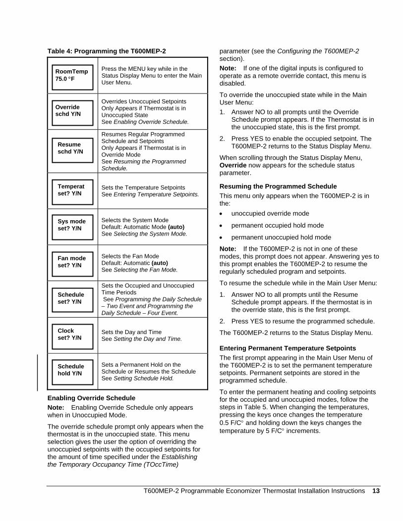
Table 4: Programming the T600MEP-2
Press the MENU key while in the Status Display Menu to enter the Main User Menu.
Overrides Unoccupied Setpoints Only Appears if Thermostat is in Unoccupied State
EnNowh
Ththseunthth
parameter (see the Configuring the T600MEP-2 section). Note: If one of the digital inputs is configured to operate as a remote override contact, this menu is disabled.
RoomTemp 75.0 °F
To override the unoccupied state while in the Main User Menu:
1. Answer NO to all prompts until the Override
Override schd Y/NSee Enabling Override Schedule.
Resumes Regular Programmed Schedule and Setpoints Only Appears if Thermostat is in Override Mode See Resuming the Programmed Schedule.
Sets the Temperature Setpoints See Entering Temperature Setpoints.
Selects the System Mode Default: Automatic Mode (auto) See Selecting the System Mode.
Selects the Fan Mode Default: Automatic (auto) See Selecting the Fan Mode.
Sets the Occupied and Unoccupied Time Periods See Programming the Daily Schedule – Two Event and Programming the Daily Schedule – Four Event.
Sets the Day and Time See Setting the Day and Time.
Sets a Permanent Hold on the Schedule or Resumes the Schedule See Setting Schedule Hold.
abling Override Schedule te: Enabling Override Schedule only appears en in Unoccupied Mode.
e override schedule prompt only appears when the ermostat is in the unoccupied state. This menu lection gives the user the option of overriding the occupied setpoints with the occupied setpoints for
e amount of time specified under the Establishing e Temporary Occupancy Time (TOccTime)
Schedule prompt appears. If the Thermostat is in the unoccupied state, this is the first prompt.
2. Press YES to enable the occupied setpoint. The T600MEP-2 returns to the Status Display Menu. Resume
schd Y/N When scrolling through the Status Display Menu, Override now appears for the schedule status parameter.
Resuming the Programmed Schedule Temperat set? Y/N This menu only appears when the T600MEP-2 is in
the: • unoccupied override mode
Sys mode set? Y/N • permanent occupied hold mode
• permanent unoccupied hold mode
Note: If the T600MEP-2 is not in one of these modes, this prompt does not appear. Answering yes to this prompt enables the T600MEP-2 to resume the regularly scheduled program and setpoints.
Fan mode set? Y/N
To resume the schedule while in the Main User Menu:
1. Answer NO to all prompts until the Resume Schedule prompt appears. If the thermostat is in the override state, this is the first prompt.
Schedule set? Y/N
2. Press YES to resume the programmed schedule. Clock set? Y/N
The T600MEP-2 returns to the Status Display Menu.
Entering Permanent Temperature Setpoints The first prompt appearing in the Main User Menu of the T600MEP-2 is to set the permanent temperature setpoints. Permanent setpoints are stored in the programmed schedule.
Schedule hold Y/N
To enter the permanent heating and cooling setpoints for the occupied and unoccupied modes, follow the steps in Table 5. When changing the temperatures, pressing the keys once changes the temperature 0.5 F/C° and holding down the keys changes the temperature by 5 F/C° increments.
T600MEP-2 Programmable Economizer Thermostat Installation Instructions 13

Table 5: Entering Permanent Temperature Setpoints
Press MENU from the Status Display Menu to enter the Main User Menu.
Answer NO to all prompts until the temperature set prompt appears in the display (it may be the first prompt). Press YES to enter temperature setting menu.
Press YES to change occupied cooling setpoint. Press NO to advance to occupied heating setpoint menu.
Use the UP/DOWN arrow keys to set temperature. Press YES to store value and advance to next menu.
Press YES to change the occupied heating setpoint. Press NO to advance to unoccupied cooling setpoint menu.
Use the UP/DOWN arrow keys to set temperature. Press YES to store value and advance to next menu.
Press YES to change the unoccupied cooling setpoint. Press NO to advance to the unoccupied heating setpoint.
Use the UP/DOWN arrow keys to set temperature. Press YES to store value and advance to next menu.
Press YES to change the unoccupied heating setpoint. Press NO to advance to temperature display units.
Use the UP/DOWN arrow keys to set temperature. Press YES to store value and advance to next menu.
Press YES to set the display units to °F or °C. Press NO to advance to temperature setpoint type menu.
Press YES to return to the Status Display Menu or NO to re-enter the temperature setting menu.
Exit? Y/N
RoomTemp 75.0°F
Entering Temporary Temperature Setpoints To temporarily change the setpoint:
Press the UP/DOWN arrow keys to change the temporary setpoint for the current mode of operation.
Temperat set? Y/N
Note: Whether the thermostat is heating or cooling, the respective setpoint is temporarily adjusted.
Cooling set? Y/N
Note: To toggle between the temporary heating and cooling setpoints, press the NO key while changing the temporary setpoints.
Ending Temporary Temperature Setpoints Cooling 75.0°F The temporary setpoints remain in effect for the
duration set in the Temporary Occupancy Time parameter (TOccTime) or until manually released.
To release the temporary setpoint sooner, while in the main User Menu: Heating
set? Y/N 1. Answer YES to the first prompt to appear.
2. If the thermostat does not immediately return to the Status Display Menu, press MENU again and YES to exit the Main User Menu.
Heating 68.0°F
The setpoint reverts to the Permanent Temperature Setpoint.
Unocc CL set? Y/N Selecting the System Mode
The T600MEP-2 has four system modes.
• Automatic Mode (auto) Automatic changeover between heating and cooling. This is the default setting. Unocc CL
80.0°F • Cooling Mode (cool)
Cooling operation only. • Heating Mode (heat)
Heating operation only. Unocc HT set? Y/N
• Off Mode (off) The T600MEP-2 is off; however, when frost protection is on (see Enabling Frost Protection [Frost pr] section) the thermostat still calls for heat, if required.
Unocc HT 62.0°F
To set the system mode while in the Main User Menu:
1. Answer NO to all prompts until the system mode prompt appears in the display. Press YES to set the system mode.
°F/°C set? Y/N
2. Use the UP/DOWN arrow keys to locate the desired system mode. Press YES to select the desired system mode.
14 T600MEP-2 Programmable Economizer Thermostat Installation Instructions

3. Press YES to return to the Status Display Menu or NO to return to the system mode selection menu.
Selecting the Fan Mode The T600MEP-2 has three fan mode settings. • On Fan Mode (on)
Energizes the fan all the time for both occupied and unoccupied periods (even if the system mode is set to off).
• Automatic Fan Mode (auto) Operates the fan only on a call for heating or cooling for both occupied and unoccupied periods. This is the default setting.
• Smart Fan Mode (smart) Energizes the fan all the time for occupied periods and only on a call for heating and cooling in unoccupied periods.
To select the fan mode while in the Main User Menu: 1. Answer NO to all prompts until the fan mode
prompt appears in the display. Press YES to set the fan mode.
2. Use the UP/DOWN arrow keys to locate the desired fan mode. Press YES to select the desired fan mode.
3. Press YES to return to the Status Display Menu or NO to return to the fan mode selection menu.
Programming the Daily Schedule – Two-Event The schedule setting menu is used to enter the occupied and unoccupied time periods for each day of the week. The schedule-setting menu reflects either a two-or four-event schedule per day based on what was selected in the Selecting the Number of Events (2/4event) parameter during the configuring process. If the schedule-setting menu does not reflect a two-event schedule, return to the Selecting the Number of Events (2/4event) menu in the configuration process and select two events. When changing the time, press the UP/DOWN arrow keys to change the time in 1-minute increments. Hold the keys down to change the time in 30-minute increments. Note: Programming one of the digital inputs to remote NSB disables menu. To set the time schedule for two-event schedule, follow the steps in Table 6. See Events 1 and 2 in Table 6 for an example of a two-event office schedule.
Table 6: Programming the Daily Schedule – Two-Event
Press MENU from the Status Display Menu to enter the Main User Menu.
Answer NO to all prompts until the schedule set prompt appears in the display. Press YES to enter the scheduling menu.
Press YES to set the schedule for Monday or NO to advance to Tuesday.
Press YES to set the occupied start time for Monday or NO to advance to Tuesday (selecting NO will leave the thermostat in the unoccupied mode for the entire day).
Use the UP/DOWN arrow keys to set the occupied start time. Press YES to enter the time.
Use the UP/DOWN arrow keys to set the unoccupied start time. Press YES to enter the time.
Press YES to set the schedule for Tuesday or NO to advance to Wednesday.
Press YES to copy the schedule from the previous day. Press NO to set a different schedule.
If YES was pressed, the next prompt will be for Wednesday. Repeat procedure for all days of the week.
After setting the schedule for all days of the week, following the last entry for Sunday, press YES to return to the Status Display Menu or NO to start again at Monday.
RoomTemp75.0°F
Scheduleset? Y/N
Mondayset? Y/N
Occupiedday? Y/N
Occupied12:00 AM
Unoccup12:00 AM
Tuesdayset? Y/N
Copy Y/Nprevious
Wednesdaset? Y/N
Exit? Y/N
T600MEP-2 Programmable Economizer Thermostat Installation Instructions 15

Programming the Daily Schedule – Four-Event The schedule setting menu is used to enter the occupied and unoccupied time periods for each day of the week. The schedule-setting menu reflects either a two- or four-event schedule per day based on what was selected in the Selecting the Number of Events (2/4event) menu during the configuring process. If the schedule-setting menu does not reflect a four-event schedule, return to the Selecting the Number of Events (2/4event) menu in the configuration process and select four events.
When changing the time, pressing the UP/DOWN arrow keys changes the time in 1-minute increments. Holding the keys down changes the time in 30-minute increments.
Note: Programming one of the digital inputs to remote NSB disables menu. To set the time schedule for a four-event schedule, follow the steps in Table 7. Table 8 shows an example of a four-event office schedule.
Table 7: Programming the Daily Schedule – Four-Event
Press MENU from the Status Display Menu to enter the Main User
Press YES to set the occupied start time for Monday or NO to advance to Tuesday (selecting NO leaves the thermostat in the unoccupied mode for the entire day).
Use the UP/DOWN arrow keys to set the first occupied start time. Press YES to enter the time.
Use the UP/DOWN arrow keys to set the first unoccupied start time. Press YES to enter the time.
Use the UP/DOWN arrow keys to set the second occupied start time. Press YES to enter the time.
Use the UP/DOWN arrow keys to set the second unoccupied start time. Press YES to enter the time.
Press YES to set the schedule for Tuesday or NO to advance to Wednesday.
Occupiedday? Y/N
Occupied12:00 AM
Unoccup12:00 AM
Occupie212:00 AM
Unoccup212:00 AM
Tuesdayset? Y/N
16
RoomTemp75.0°F
Menu.
Answer NO to all prompts until the schedule set prompt appears in the display. Press YES to enter the scheduling menu.
Press YES to set the schedule for Monday or NO to advance to Tuesday.
Press YES to copy the schedule from the previous day. Press NO to set a different schedule.
If YES was pressed, the next prompt will be for Wednesday. Repeat procedure for all days of the week.
After setting the schedule for all days of the week, following the last entry for Sunday, press YES to return to the Status Display Menu or NO to start again at Monday.
Copy Y/Nprevious Schedule
set? Y/N
Wednesdaset? N/A Monday
set? Y/N
Exit? Y/N
T600MEP-2 Programmable Economizer Thermostat Installation Instructions

Table 8: Example of a Four-Event Office Schedule Event #1 Event #2 Event #3 Event #4
Occupied Unoccupied Occupied 2 Unoccupied 2 Event
Cool Heat Cool Heat Cool Heat Cool Heat 72°F
(22°C) 70°F
(21°C) 80°F
(27°C) 62°F
(17°C) 72°F
(22°C) 70°F
(21°C) 80°F
(27°C) 62°F
(17°C) Monday 7:00 A.M. 5:00 P.M. 12:00 P.M.* 12:00 P.M.* Tuesday 7:00 A.M. 5:00 P.M. 12:00 P.M.* 12:00 P.M.*
Wednesday 7:00 A.M. 5:00 P.M. 12:00 P.M.* 12:00 P.M.* Thursday 7:00 A.M. 5:00 P.M. 7:00 P.M. 10:30 P.M.
Friday 7:00 A.M. 5:00 P.M. 7:00 P.M. 10:30 P.M. Saturday 12:00 P.M.* 12:00 P.M.* 12:00 P.M.* 12:00 P.M.* Sunday 12:00 P.M.* 12:00 P.M.* 12:00 P.M.* 12:00 P.M.*
* Programming events to the same time cancels the last period and leaves the thermostat in unoccupied mode.
Setting the Day and Time Upon initial power-up (or after a power loss of greater than 6 hours), the T600MEP-2 shows a SetClock alarm. As the thermostat scrolls through the Status Display Menu, the SetClock message causes the backlight to light up until the clock is set. When adjusting the time with the UP/DOWN arrow keys, holding the keys down changes the time in 30-minute increments. To set the clock while in the Main User Menu:
1. Answer NO to all prompts until the clock set prompt appears in the display. Press YES to enter the clock set menu.
2. Press YES to set the time or NO to advance to the day set menu.
3. Use the UP/DOWN arrow keys to adjust the time. When the correct time is displayed, press YES to store the time.
4. Press YES to enter the day set menu or NO to enter the clock format menu.
5. Use the UP/DOWN arrow keys to adjust the day. When the correct day is displayed, press YES to store the day.
6. Press YES to choose the time format or NO to access the Main User Menu exit prompt.
7. Use the UP/DOWN arrow keys to select the desired time format. Press YES to enter format.
8. Press YES to return to the Status Display Menu or NO to return to the time set menu.
When the thermostat scrolls through the day and time, the new day and time should be displayed (and no alarm/backlight should be present). If the day or time is incorrect, repeat the Setting the Day and Time procedure.
Setting Schedule Hold This menu is used to set a permanent hold on the internal scheduling or resume the schedule. The permanent hold is typically used for unscheduled events that extend for long periods of time.
Note: Displayed only if Digital Input DI1 or DI2 is configured for remote NSB.
Following are the three selections for this menu:
• Permanent Occupied Hold (occ hold) This selection puts the thermostat into a permanent occupied mode using the occupied setpoints. Occupied hold appears in the Status Display Menu when this selection is active.
• Permanent Unoccupied Hold This selection puts the T600MEP-2 into a permanent unoccupied mode using the unoccupied setpoints. Unoccup hold appears in the Status Display Menu when this selection is active.
• Resume This selection cancels the permanent hold and enables the regular program schedule.
To enable the permanent hold feature while in the Main User Menu:
1. Answer NO to all prompts until the schedule hold prompt appears in the display. Press YES to enter the schedule hold type menu.
T600MEP-2 Programmable Economizer Thermostat Installation Instructions 17

Table 9: Optional Accessories (Includes Mounting Hardware)
2. Use the UP/DOWN arrow keys to locate the desired permanent hold type (or resume schedule). Press YES to enter the choice. Item Product Code
Number Remote Indoor Temperature Sensor SEN-600-1 Outdoor Air Temperature Sensor SEN-600-2 Duct Mount Temperature Sensor SEN-600-3 Remote Indoor Temperature Sensor with Occupancy Override and LED SEN-600-4
3. Press YES to return to the Status Display Menu or NO to change the schedule hold selection again.
Accessories Using the information in Table 9, contact the nearest Johnson Controls® branch office or wholesale distributor to order these accessories.
Technical Specifications Product T600MEP-2 Programmable Economizer Thermostat
Power Requirements 20-30 VAC, 50/60 Hz, 24 VAC nominal, Class 2 or Safety Extra Low Voltage (SELV) Relay Contact Rating
Maximum Inductive 1 ampere with in-rush surges up to 3 amperes, 30 VAC maximum, Class 2
Digital Inputs Relay dry contact only across the C terminal to DI1 or DI2 Economizer Output 0 to 10 VDC into 2 K ohm resistance minimum
Recommended Wire Size 18 gauge maximum, 22 gauge recommended Thermostat Measurement
Range -40 to 122°F (-40 to 50°C)
Sensor Type: Resolution:
Control Accuracy
Local 10 K ohm NTC thermistor ±0.2F° (±0.1C°) ±0.9F° (±0.5C°) @ 70°F (21°C) typical calibrated
Outdoor Air Temperature Indication Range
-40 to 50°C (-40 to 122°F)
Setpoint Control Range Cooling: 54 to 100°F (12 to 37.5°C) in 1/2 degree increments Heating: 40 to 90°F (4.5 to 32°C) in 1/2 degree increments
Minimum Deadband (Between heating and cooling) 2F° or 1C° Ambient Operating
Conditions 32 to 122°F (0 to 50°C); 0 to 95% RH noncondensing
Ambient Storage Conditions
-22 to 122°F (-30 to 50°C); 0% to 95% RH noncondensing
Dimensions (H x W x D) 4.94 x 3.38 x 1.13 in. (125 x 86 x 29 mm) Shipping Weight 0.75 lb (0.34 kg)
UL and cUL Listing File E27734 with CCN’s XAPX (US, UL 873) and XAPX7 (Canada, CSA C22.2 No. 24) FCC Compliance This equipment has been tested and found to comply with the limits for a Class A digital
device and verified to Class B pursuant tos Part 15 of FCC Rules. These limits are designed to provide reasonable protection against harmful interference when this equipment is operated in a commercial environment. This equipment generates, uses, and can radiate radio frequency energy and, if not installed and used in accordance with the instruction manual, may cause harmful interference to radio communications. Operation of this equipment in a residential area is likely to cause harmful interference, in which case the user will be required to correct the interference at his/her own expense.
Industry Canada This Class A digital apparatus meets all of the requirements of the Canadian Interference-Causing Equipment Regulations. Cet appareil numérique de la Classe A respecte toutes les exigences du Règlement sur le materiél brouilleur du Canada.
The performance specifications are nominal and conform to acceptable industry standards. For application at conditions beyond these specifications, consult the local Johnson Controls office. Johnson Controls, Inc. shall not be liable for damages resulting from misapplication or misuse of its products.
Controls Group 507 E. Michigan Street P.O. Box 423 Printed in U.S.A.Milwaukee, WI 53201 www.johnsoncontrols.com
18 T600MEP-2 Programmable Economizer Thermostat Installation Instructions