t8a - irot.in
TRANSCRIPT
T8A
INDIAN RAILWAYS INSTITUTE OF SIGNAL ENGINEERING & TELECOMMUNICATIONS
SECUNDERABAD - 500 017
Issued in October 2009
VISION:
MISSION:
TO MAKE IRISET AN INSTITUTE OF INTERNATIONAL REPUTE, SETTING ITS OWN STANDARDS AND BENCHMARKS
TO ENHANCE QUALITY AND INCREASE PRODUCTIVITY OF SIGNALLING & TELECOMMUNICATION PERSONNEL THROUGH TRAINING
T8A
LINE PLANT PRACTICE OVERHEAD LINES
CONTENTS
S.No Chapter Page No
1 Overhead Telecom Lines 1
2 Posts 3
3 Channel Iron Brackets or Cross arms and other Components 6
4 Line Wires 12
5 Stays 35
6 Periodical Maintenance and Inspection of Lines 45
7 Protection from Power Lines and Inductive Co-ordination 69
© IRISET
http://www.iriset.ac.in
Prepared by Y. V. Prasad, IMW - 3
Approved by S. K. Biswas, Sr. Professor - Tele
DTP and Drawings K.Srinivas, JE II(D)
Date of Issue September 2005
Edition No 01
First re-print October 2008
No. of Pages 88
No.of Sheets 45
“This is the Intellectual property for exclusive use of Indian Railways. No part of this publication may be stored in a retrieval system, transmitted or reproduced in any way, including but not limited to photo copy, photograph, magnetic, optical or other record without the prior agreement and written permission of IRISET, Secunderabad, India”

IRISET 1 T8A - Line Pant Practice – Overhead Lines
CHAPTER 1
OVERHEAD TELECOM LINES
1.0. Introduction
On Indian Railways the Overhead telecom lines can be classified as
• Main line alignment
• Local line alignment
1.1. Main line alignment
Main lines, suitable for taking long distance communications circuits for control working,
Administrative trunk circuits etc. which extends several hundreds of Kms. and Block
circuits, LC gate lines on the same alignment.
Requirement of main lines over head plant
• To carry Railway control circuits i.e. section control, Dy. Control etc.
• To carry Administrative trunk (ADM) circuits
• To carry block circuit
• To carry Train wire circuits
• To carry any other circuits like LC gate telephones.
♦ Control Circuits: For efficient movement of trains and optimum use of line capacity
ensuring the safety. A controller is connected to wayside stations for controlling the
movement of trains.
♦ Block Circuits: For safety of train movement. Intercommunication between two
adjacent stations is established for safe running of trains.
♦ Magneto Telephone Circuits: Point to point communication between cabins, station
master and various points in yard.
♦ Gate circuits: Point to point connection between LC gates and cabins or station
masters
♦ Carrier Telephones Circuits: For administrative trunk circuits for connecting
headquarters to divisional offices and divisional offices to important points like Loco
Shed, Workshop etc.

Overhead Telecom Lines
IRISET 2 T8A - Line Pant Practice – Overhead Lines
1.2. Local Line Systems
Local lines suitable for local telephone exchange circuits over short distance, eg. From
cable termination point (DP) to subscriber’s wall brackets.
1.3. Other types
♦ Town Lines: These lines are erected on tall and stout rail posts, so that town traffic
are not interfered. Carry circuits to the main exchange.
♦ Hill Lines: Are erected taking advantage of the natural formation of the hill. Fanning
the wires is done for achieving greater span length.
♦ Temporary Lines: Are erected in cases of urgency using saplings, bamboos or
trees on temporary basis. Only GI wires are used. Telecommunication facilities are
provided with semi permanent lines also. Greater wire spacing is provided by
erecting two wires on the extremities of a cross arm.

Overhead Telecom Lines
IRISET 2(i) T8A - Line Pant Practi ce – Overhead Lines
Objective: Fill up the blanks with suitable words: 1) Magneto circuits are used for _________ to ___________ . communication.
2) Block circuit is between two __________ _________ only. 3) Local lines suitable for over ________ distances only. 4) L.C. gate circuits are carried on ________ alignment. 5) Temporary lines are erected in cases of ____________. 6) The main line alignment carries _________ _________ _________ circuits.
Subjective: 1) What is the purpose of “Main Line Alignment”? Explain the different circuits coming under
it?
2) What is the purpose of “Local Line Systems”? Explain about the other types of lines?
Posts
IRISET 3 T8A - Line Pant Practice – Overhead Lines
CHAPTER 2
POSTS
2.0. The main types of Posts:
♦ Released rail posts flat footed or bull headed
♦ Tubular posts of Telescopic construction
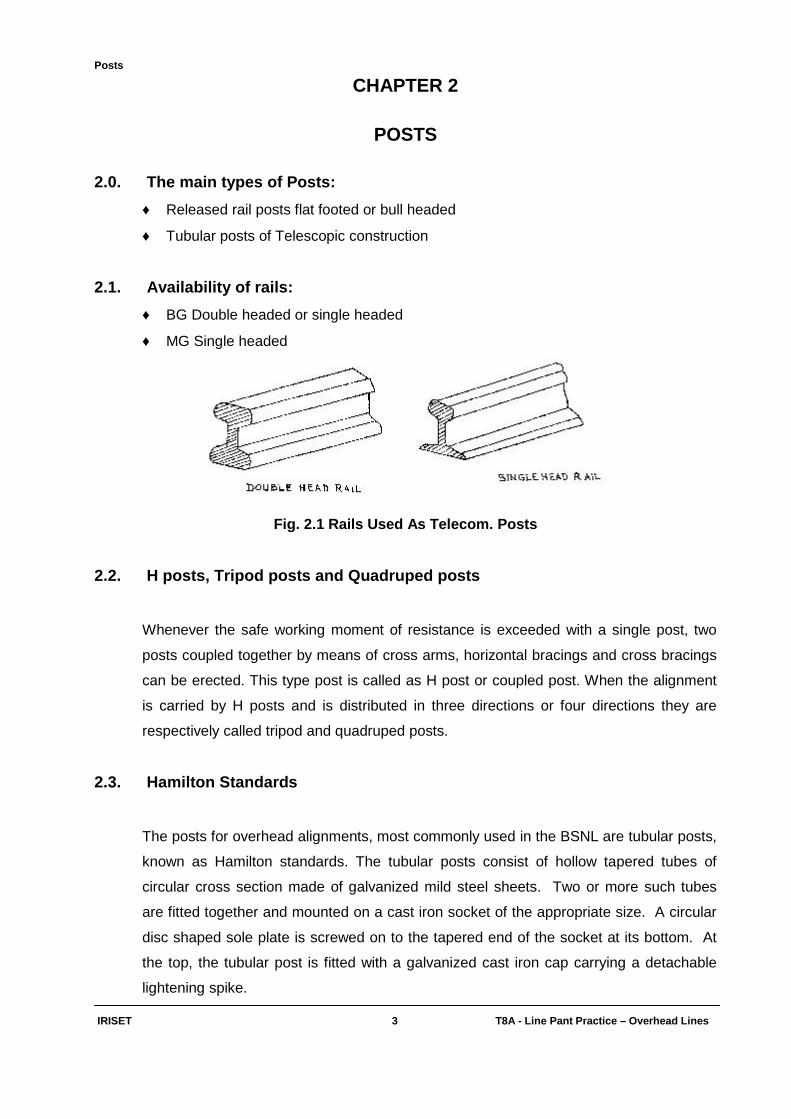
2.1. Availability of rails:
♦ BG Double headed or single headed
♦ MG Single headed
Fig. 2.1 Rails Used As Telecom. Posts
2.2. H posts, Tripod posts and Quadruped posts
Whenever the safe working moment of resistance is exceeded with a single post, two
posts coupled together by means of cross arms, horizontal bracings and cross bracings
can be erected. This type post is called as H post or coupled post. When the alignment
is carried by H posts and is distributed in three directions or four directions they are
respectively called tripod and quadruped posts.
2.3. Hamilton Standards
The posts for overhead alignments, most commonly used in the BSNL are tubular posts,
known as Hamilton standards. The tubular posts consist of hollow tapered tubes of
circular cross section made of galvanized mild steel sheets. Two or more such tubes
are fitted together and mounted on a cast iron socket of the appropriate size. A circular
disc shaped sole plate is screwed on to the tapered end of the socket at its bottom. At
the top, the tubular post is fitted with a galvanized cast iron cap carrying a detachable
lightening spike.
Posts
IRISET 4 T8A - Line Pant Practice – Overhead Lines
2.4. Sockets
Sockets form the base of tubular posts. They are made of cast iron and are tarred.
Hence, they are corrosion resistant. The vent near the broader end hole provides an
outlet for rain water that may collect inside the post.
2.5. Sole Plates
Sole plates are circular discs provided with a circular hole in the centre. Sole plates are
made of cast iron and are tarred, corrosion resistant. Sole plate gives a greater bearing
surface to the base of the post, viz., the socket, and hence, increases the stability of the
post. It also prevents the post from sinking in swampy ground or in black cotton soil.
2.6. Caps
All posts are provided with a cap, fitted on the top-most component tube to prevent
rainwater filling up the post. All caps are provided with a hole at the top, which is
intended to take either an insulator stalk or a lightning spike. Caps are made of cast iron
and are galvanized.
2.7. Tubular Posts
A tubular post is designated by the sizes of the component tubes, given from the top to
the bottom, used for assembling that post. The advantages of tubular post over the other
types of supports are its lightness combined with strength, ease of transportation and
handling of the component parts, ease of fitting, erection and dismantling.
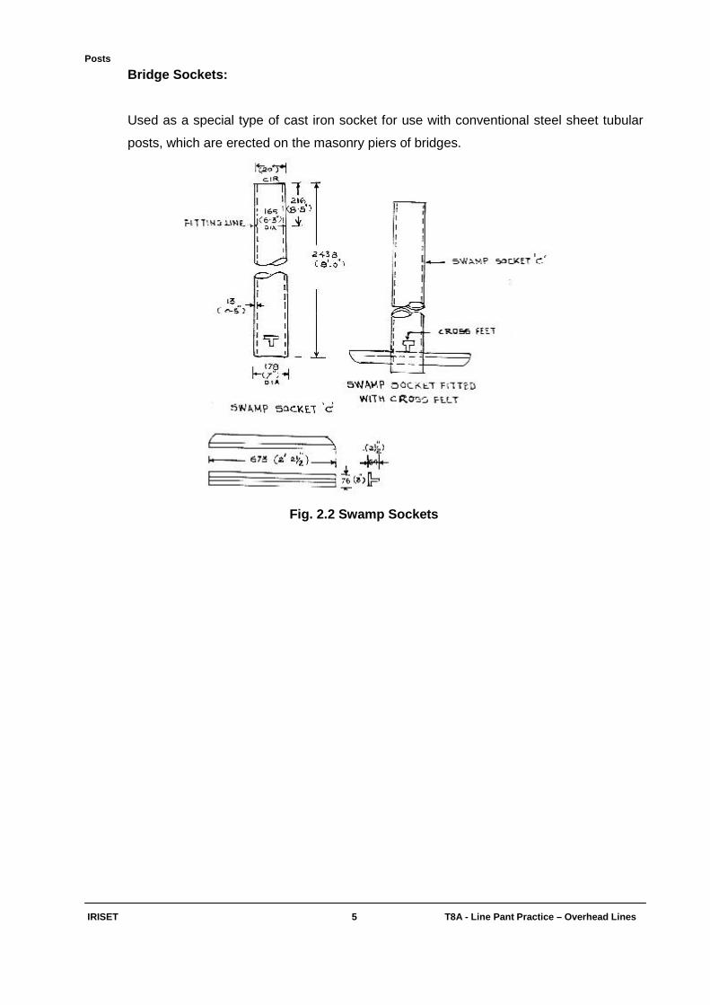
2.8. Special Types Of Sockets
Swamp sockets:
Used as the bottom component of tubular posts erected in water logged areas. These
sockets will be longer than the normal sockets.
Posts
IRISET 5 T8A - Line Pant Practice – Overhead Lines
Bridge Sockets:
Used as a special type of cast iron socket for use with conventional steel sheet tubular
posts, which are erected on the masonry piers of bridges.
Fig. 2.2 Swamp Sockets

Posts
IRISET 5(i) T8A - Line Pant Practi ce – Overhead Lines
Objective: Fill up the blanks with suitable words: 1) Coupled post is used when ___________ is exceeded with a single post.
2) Tripod is to divert the control lines for ____________directions. 3) Quadruped post is to divert the control lines for __________directions. 4) _______________gives greater bearing surface to the base of the post. 5) Caps are used for _________ posts. 6) Tubular post is the combination of __________________.
Subjective: 1) What is meant by “Post”? What are the main types of posts used for Telecom alignment?
2) Explain about the main parts of a “Hamilton tubular post”? Where it is mostly used?
3) Explain about the types of sockets used for posts?
4) Write short notes on any THREE of the following:
a) Sockets b) Sole plates c) Caps d) Tubes
Channel Iron Brackets or Cross arms &other Components
IRISET 6 T8A - Line Pant Practice – Overhead Lines
CHAPTER 3
CHANNEL IRON BRACKETS OR CROSS ARMS
AND OTHER COMPONENTS
3.0. Cross Arm
Cross arms are 40mm X 32 mm MS channel conforming to IS 3954 and have horizontal
slots on the web to allow 'U' bolts to fit them on the posts and vertical holes on flanges
for insertion of stalks.
3.1. Cross Arms for Local Lines
These cross arms provide 200 mm horizontal separation between wires and 250 mm
between pairs for single post. For local line system cross arms are available for taking 2
wires to 8 wires. Only 8 wire cross arms with 300mm spacing between wires and pairs
should be used with coupled posts. Cross arms with single channel and double channel
are available. Double channel types are used for Tripods and Quadrupeds.
3.2. Cross Arms for Main Lines
Cross arms 2 Way, 4 Way, 6 Way & 8 Way are available. The spacing between wires,
pairs and cross arms is the same equivalent to 300 mm. These are used for VF circuits.
As these brackets are not symmetrically fixed with respect to the post, it will be difficult to
keep them perfectly horizontal by themselves. To overcome this difficulty, every post
fitted with one or more offset telegraph brackets. Off set brackets is also provided with a
strut and a tie where called for.

Channel Iron Brackets or Cross arms &other Components
IRISET 7 T8A - Line Pant Practice – Overhead Lines
Fig. 3.1 Different Types Of Cross Arms
Channel Iron Brackets or Cross arms &other Components
IRISET 8 T8A - Line Pant Practice – Overhead Lines
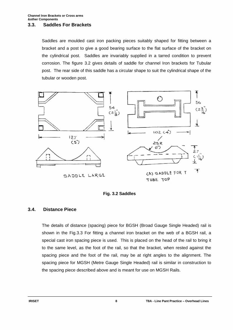
3.3. Saddles For Brackets
Saddles are moulded cast iron packing pieces suitably shaped for fitting between a
bracket and a post to give a good bearing surface to the flat surface of the bracket on
the cylindrical post. Saddles are invariably supplied in a tarred condition to prevent
corrosion. The figure 3.2 gives details of saddle for channel Iron brackets for Tubular
post. The rear side of this saddle has a circular shape to suit the cylindrical shape of the
tubular or wooden post.
Fig. 3.2 Saddles
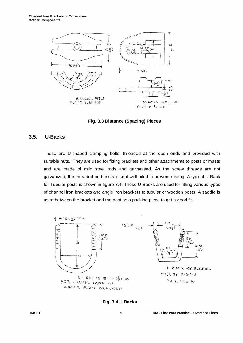
3.4. Distance Piece
The details of distance (spacing) piece for BGSH (Broad Gauge Single Headed) rail is
shown in the Fig.3.3 For fitting a channel iron bracket on the web of a BGSH rail, a
special cast iron spacing piece is used. This is placed on the head of the rail to bring it
to the same level, as the foot of the rail, so that the bracket, when rested against the
spacing piece and the foot of the rail, may be at right angles to the alignment. The
spacing piece for MGSH (Metre Gauge Single Headed) rail is similar in construction to
the spacing piece described above and is meant for use on MGSH Rails.
Channel Iron Brackets or Cross arms &other Components
IRISET 9 T8A - Line Pant Practice – Overhead Lines
Fig. 3.3 Distance (Spacing) Pieces
3.5. U-Backs
These are U-shaped clamping bolts, threaded at the open ends and provided with
suitable nuts. They are used for fitting brackets and other attachments to posts or masts
and are made of mild steel rods and galvanised. As the screw threads are not
galvanized, the threaded portions are kept well oiled to prevent rusting. A typical U-Back
for Tubular posts is shown in figure 3.4. These U-Backs are used for fitting various types
of channel iron brackets and angle iron brackets to tubular or wooden posts. A saddle is
used between the bracket and the post as a packing piece to get a good fit.
Fig. 3.4 U Backs
Channel Iron Brackets or Cross arms &other Components
IRISET 10 T8A - Line Pant Practic e – Overhead Lines
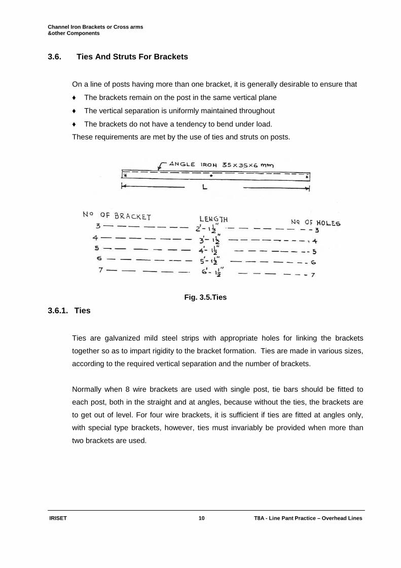
3.6. Ties And Struts For Brackets
On a line of posts having more than one bracket, it is generally desirable to ensure that
♦ The brackets remain on the post in the same vertical plane
♦ The vertical separation is uniformly maintained throughout
♦ The brackets do not have a tendency to bend under load.
These requirements are met by the use of ties and struts on posts.
Fig. 3.5.Ties
3.6.1. Ties
Ties are galvanized mild steel strips with appropriate holes for linking the brackets
together so as to impart rigidity to the bracket formation. Ties are made in various sizes,
according to the required vertical separation and the number of brackets.
Normally when 8 wire brackets are used with single post, tie bars should be fitted to
each post, both in the straight and at angles, because without the ties, the brackets are
to get out of level. For four wire brackets, it is sufficient if ties are fitted at angles only,
with special type brackets, however, ties must invariably be provided when more than
two brackets are used.
Channel Iron Brackets or Cross arms &other Components
IRISET 11 T8A - Line Pant Practic e – Overhead Lines
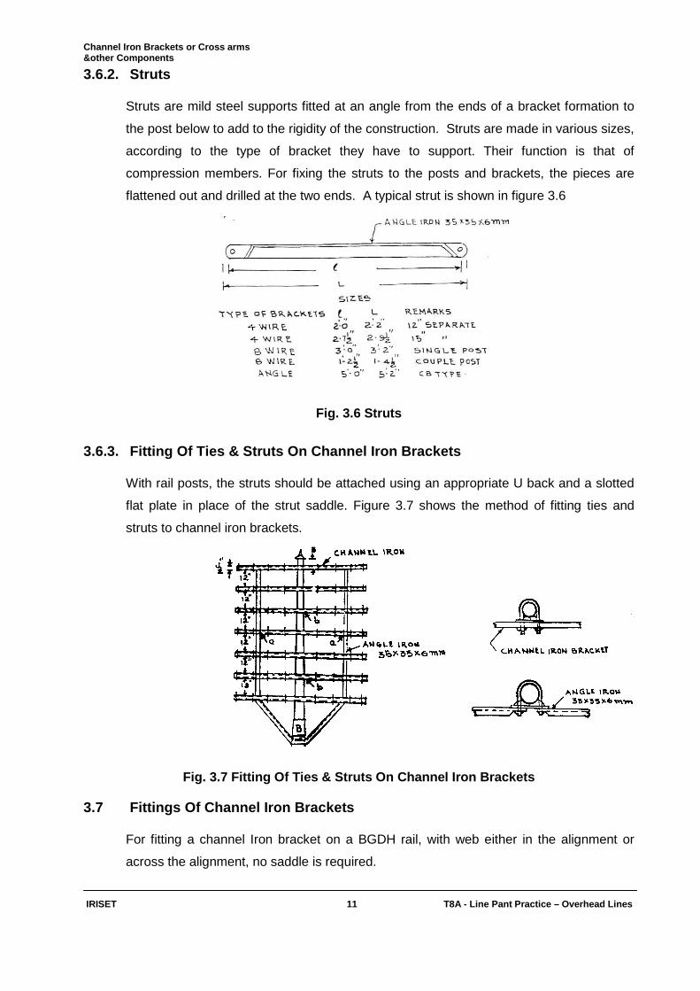
3.6.2. Struts
Struts are mild steel supports fitted at an angle from the ends of a bracket formation to
the post below to add to the rigidity of the construction. Struts are made in various sizes,
according to the type of bracket they have to support. Their function is that of
compression members. For fixing the struts to the posts and brackets, the pieces are
flattened out and drilled at the two ends. A typical strut is shown in figure 3.6
Fig. 3.6 Struts
3.6.3. Fitting Of Ties & Struts On Channel Iron Br ackets
With rail posts, the struts should be attached using an appropriate U back and a slotted
flat plate in place of the strut saddle. Figure 3.7 shows the method of fitting ties and
struts to channel iron brackets.
Fig. 3.7 Fitting Of Ties & Struts On Channel Iron B rackets 3.7 Fittings Of Channel Iron Brackets
For fitting a channel Iron bracket on a BGDH rail, with web either in the alignment or
across the alignment, no saddle is required.

Channel Iron Brackets or Cross arms &other Components
IRISET 11(i) T8A - Line Pant Practic e – Overhead Lines
Objective: Fill up the blanks with suitable words: 1) ___________ is used for fitting the brackets and other attachments to posts on
Telecommunication lines.
2) Saddles are used for fitting between ____________ a post. 3) The distant piece is placed on the _________of the rail post to bring it to the same level. 4) Struts are fitted between ____________ and _____________. 5) Ties links the _____________ together.
Subjective: 1) What is U-Back? Where it is used? Explain about the different types of U-Backs with neat
figures?
2) What is meant by Strut and Tie? Show how they are fixed on the post?
3) Write short notes on the following
a) Saddle b) Ties and struts c) Distance piece
4) What is meant by “Cross arm”? Explain about the cross arms used for Maine line and Local
lines? Draw the figure of 4-way cross arm?

Line Wires
IRISET 12 T8A - Line Pant Practic e – Overhead Lines
CHAPTER 4
LINE WIRES
4.0. Introduction
The type and size of wire is to be chosen depending upon the type of circuit, its length,
resistance of the conductors and also the attenuation in case of voice frequency and
carrier circuits. For train controlling signaling circuits like block circuits on physical wires
the value of resistance is important. The attenuation of signals in the VF and Carrier
circuits depends on the resistance, inductance, leakance and capacitance of the wires
and is expressed in db. The limits of attenuation on overhead lines are given below for
various circuits.
4.1. Max. permissible Limits Of Attenuation:
Description of Line Loop Resistance Attenuation
Auto Exchange line 600 ---
Junction Line 350 ---
Trunk Units between two exchanges --- 12db
Control Line --- 20 db
Table. 4.1 Max. permissible Limits Of Attenuation
Basing on these factors, the type and size of the line wire to be used is decided.
4.2. Bare Line Wires
Despite greater fault liability, bare overhead line wires are most commonly used, mainly
for reasons of economy and superior transmission characteristics. The chief
considerations for a line wire are adequate mechanical strength for working, freedom
from corrosion and low resistance and self-inductance.
Line Wires
IRISET 13 T8A - Line Pant Practic e – Overhead Lines
4.3. The various types of Line Wires used in Telec om are
♦ Galvanized Iron Wire
♦ Copper weld wire
♦ Aluminum conductor steel reinforced wire (ACSR)
4.3.1. Galvanized Iron Wires
They are manufactured from low carbon steel and protected by a coating of thin film of
zinc. Due to their higher resistance, inductance and relatively shorter life, the use of iron
wires is not generally favoured. They are, however, still used for local telephone lines
and for short distance trunk lines. The higher gauges are normally used for long distance
telephone lines.
The GI wires used by Indian Railway Telecommunicati ons are
♦ 1.50mm gauge Binding Wire
♦ 1.80mm gauge Local Telephone Lines
♦ 2.12mm gauge Main Line Short Distance Magneto Lines
♦ 2.50mm gauge Gate Telephone Lines
♦ 3.55mm gauge Block, Train Wire,
4.3.2. Copper weld Wire
This type of wire combines the conductivity of copper with the tensile strength of steel.
Solid copper conductors have better characteristics, but in the field of high frequency
transmission (above 60 KHz, copper weld has a lower attenuation. In a solid copper
wire, although the "skin effect" tends to force the higher frequency currents to the outer
surface, there remains an out of phase component in the inner portion.
The copper weld wires used by Indian Railway Teleco mmunications are
♦ 3.25mm gauge Short distance train control & Admin. Trunks
♦ 4.81mm gauge Long distance train control & Admin. Trunks
Line Wires
IRISET 14 T8A - Line Pant Practic e – Overhead Lines
4.3.3. Aluminium conductor steel reinforced (ACSR) wires
Due to the following advantages ACSR wires were preferred:
♦ Free availability in India
♦ Thefts comparatively less than copper since ACSR is cheaper
♦ No foreign exchange is involved
♦ ACSR wires are 20% lighter and 50% stronger than copper wires of equal size
♦ Because of lightness, the posts and supports used can be of less strength.
♦ Cost of transport is less.
♦ Minimum breaking load of 200 lbs / mile copper wire is 280 Kg while that of ACSR
(6/1/1.5) is 425 kg. Hence longer spans can be used and the number of posts per Km
could be less.
♦ Conductivity: The DC resistance of ACSR 6/1/1.5 is 2.7 ohms / Km and is almost the
same as that of 200 lbs/mile copper wire.
♦ Working range of control circuits available with ACSR is considerably better than that
with copper conductors.
4.3.4.1. Use Of ACSR In Indian Railway telecom. Cir cuits:
♦ ACSR 6 / 1/ 1.50 . . . . . . . . . . . . . Short distance section & deputy control circuits,
admin. trunks.
♦ ACSR 6 / 1/ 1.96 . . . . . . . . . . . . . Long distance section & deputy control circuits,
admin. trunks.
♦ ACSR 6 / 1/ 2.11 . . . . . . . . . . . . . Carrier circuits.
4.3.4.2 ACSR wire for use near seacoasts
For areas within 30 KM from the sea atmosphere is saline and severe electrolytic action
may take place between iron core and aluminum wires causing corrosion of metals.
Specially greased ACSR shall be used in such cases. Such greases are applied to
ACSR wires around the steel core during manufacture. Before, installation in coastal
area, it is important that the ACSR wires are checked for greasing.
Line Wires
IRISET 15 T8A - Line Pant Practic e – Overhead Lines
4.4. Insulators For Bare Line Wires
The primary function of an insulator for a bare overhead telephone line is to support the
wires while restricting the leakage current flowing from the line conductor to the stalk
which supports the insulator on the bracket.
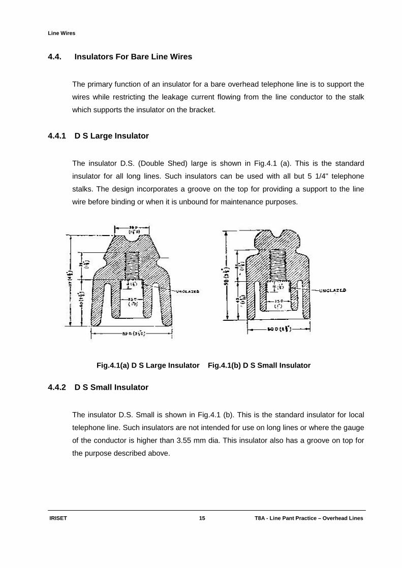
4.4.1 D S Large Insulator
The insulator D.S. (Double Shed) large is shown in Fig.4.1 (a). This is the standard
insulator for all long lines. Such insulators can be used with all but 5 1/4" telephone
stalks. The design incorporates a groove on the top for providing a support to the line
wire before binding or when it is unbound for maintenance purposes.
Fig.4.1(a) D S Large Insulator Fig.4.1(b) D S Sm all Insulator
4.4.2 D S Small Insulator
The insulator D.S. Small is shown in Fig.4.1 (b). This is the standard insulator for local
telephone line. Such insulators are not intended for use on long lines or where the gauge
of the conductor is higher than 3.55 mm dia. This insulator also has a groove on top for
the purpose described above.
Line Wires
IRISET 16 T8A - Line Pant Practic e – Overhead Lines
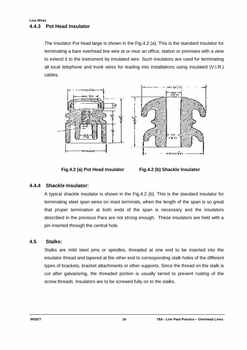
4.4.3 Pot Head Insulator
The Insulator Pot head large is shown in the Fig.4.2 (a). This is the standard insulator for
terminating a bare overhead line wire at or near an office, station or premises with a view
to extend it to the instrument by insulated wire. Such insulators are used for terminating
all local telephone and trunk wires for leading into installations using insulated (V.I.R.)
cables.
Fig.4.2 (a) Pot Head Insul ator Fig.4.2 (b) Shackle Insulator
4.4.4 Shackle Insulator:
A typical shackle insulator is shown in the Fig.4.2 (b). This is the standard insulator for
terminating steel span wires on mast terminals, when the length of the span is so great
that proper termination at both ends of the span is necessary and the insulators
described in the previous Para are not strong enough. These insulators are held with a
pin inserted through the central hole.
4.5 Stalks:
Stalks are mild steel pins or spindles, threaded at one end to be inserted into the
insulator thread and tapered at the other end to corresponding stalk holes of the different
types of brackets, bracket attachments or other supports. Since the thread on the stalk is
cut after galvanizing, the threaded portion is usually tarred to prevent rusting of the
screw threads. Insulators are to be screwed fully on to the stalks.
Line Wires
IRISET 17 T8A - Line Pant Practic e – Overhead Lines
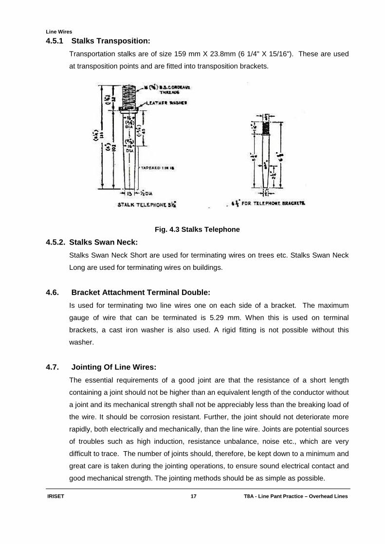
4.5.1 Stalks Transposition:
Transportation stalks are of size 159 mm X 23.8mm (6 1/4" X 15/16"). These are used
at transposition points and are fitted into transposition brackets.
Fig. 4.3 Stalks Telephone
4.5.2. Stalks Swan Neck:
Stalks Swan Neck Short are used for terminating wires on trees etc. Stalks Swan Neck
Long are used for terminating wires on buildings.
4.6. Bracket Attachment Terminal Double:
Is used for terminating two line wires one on each side of a bracket. The maximum
gauge of wire that can be terminated is 5.29 mm. When this is used on terminal
brackets, a cast iron washer is also used. A rigid fitting is not possible without this
washer.
4.7. Jointing Of Line Wires:
The essential requirements of a good joint are that the resistance of a short length
containing a joint should not be higher than an equivalent length of the conductor without
a joint and its mechanical strength shall not be appreciably less than the breaking load of
the wire. It should be corrosion resistant. Further, the joint should not deteriorate more
rapidly, both electrically and mechanically, than the line wire. Joints are potential sources
of troubles such as high induction, resistance unbalance, noise etc., which are very
difficult to trace. The number of joints should, therefore, be kept down to a minimum and
great care is taken during the jointing operations, to ensure sound electrical contact and
good mechanical strength. The jointing methods should be as simple as possible.

Line Wires
IRISET 18 T8A - Line Pant Practic e – Overhead Lines
Jointing Of GI Wires:
Tools required:
♦ Eye bolt
♦ Britannia Joint vice
♦ Binding tool
♦ Soldering bolt T shaped large
♦ Soldering bolt copper large and medium.
Fig.4.4 Tools Used For GI Wire Jointing
(a) Twist Joint:
This joint is performed on wires up to gauge 1.8 mm. Both wires should be cleaned for
about 30 cms (12 inches), straightened and made to overlap by about 40 cms (16
inches). At 20 cms (8 inches) from either end, they should be gripped firmly by Britannia
Joint hand vice. One of the free ends of the two wires should then be taken into the eye
bolt tool and twisted, four times around the adjacent line wire, with appropriate tension.
The hand vice should be taken off and put back on the twisted portion. The other free
end should now be twisted four times as before. There after the projecting ends should
be cut off with a pair of pliers. The finished joint should be soldered.
Fig. 4.5 Twist Joint
Line Wires
IRISET 19 T8A - Line Pant Practic e – Overhead Lines
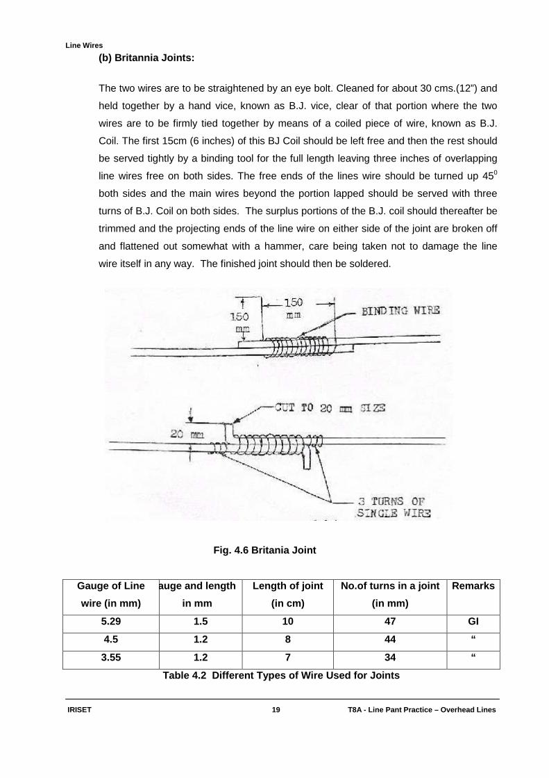
(b) Britannia Joints:
The two wires are to be straightened by an eye bolt. Cleaned for about 30 cms.(12”) and
held together by a hand vice, known as B.J. vice, clear of that portion where the two
wires are to be firmly tied together by means of a coiled piece of wire, known as B.J.
Coil. The first 15cm (6 inches) of this BJ Coil should be left free and then the rest should
be served tightly by a binding tool for the full length leaving three inches of overlapping
line wires free on both sides. The free ends of the lines wire should be turned up 450
both sides and the main wires beyond the portion lapped should be served with three
turns of B.J. Coil on both sides. The surplus portions of the B.J. coil should thereafter be
trimmed and the projecting ends of the line wire on either side of the joint are broken off
and flattened out somewhat with a hammer, care being taken not to damage the line
wire itself in any way. The finished joint should then be soldered.
Fig. 4.6 Britania Joint
Gauge of Line
wire (in mm)
Gauge and length
in mm
Length of joint
(in cm)
No.of turns in a joint
(in mm)
Remarks
5.29 1.5 10 47 GI
4.5 1.2 8 44 “
3.55 1.2 7 34 “
Table 4.2 Different Types of Wire Used for Joints
Line Wires
IRISET 20 T8A - Line Pant Practic e – Overhead Lines
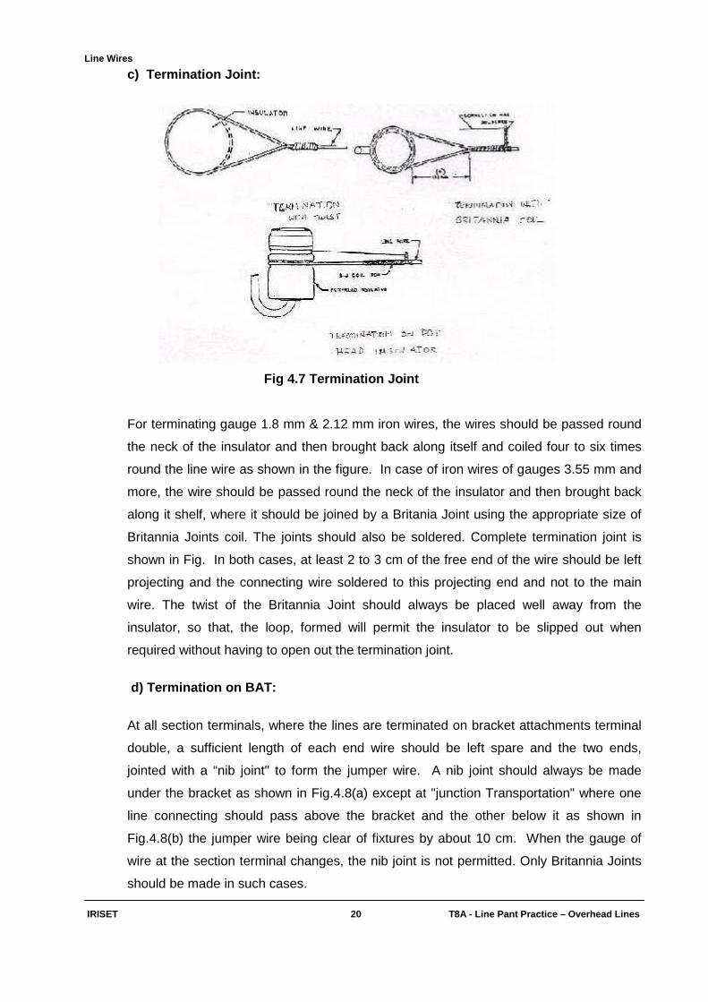
c) Termination Joint:
Fig 4.7 Termination Joint
For terminating gauge 1.8 mm & 2.12 mm iron wires, the wires should be passed round
the neck of the insulator and then brought back along itself and coiled four to six times
round the line wire as shown in the figure. In case of iron wires of gauges 3.55 mm and
more, the wire should be passed round the neck of the insulator and then brought back
along it shelf, where it should be joined by a Britania Joint using the appropriate size of
Britannia Joints coil. The joints should also be soldered. Complete termination joint is
shown in Fig. In both cases, at least 2 to 3 cm of the free end of the wire should be left
projecting and the connecting wire soldered to this projecting end and not to the main
wire. The twist of the Britannia Joint should always be placed well away from the
insulator, so that, the loop, formed will permit the insulator to be slipped out when
required without having to open out the termination joint.
d) Termination on BAT:
At all section terminals, where the lines are terminated on bracket attachments terminal
double, a sufficient length of each end wire should be left spare and the two ends,
jointed with a “nib joint" to form the jumper wire. A nib joint should always be made
under the bracket as shown in Fig.4.8(a) except at "junction Transportation" where one
line connecting should pass above the bracket and the other below it as shown in
Fig.4.8(b) the jumper wire being clear of fixtures by about 10 cm. When the gauge of
wire at the section terminal changes, the nib joint is not permitted. Only Britannia Joints
should be made in such cases.

Line Wires
IRISET 21 T8A - Line Pant Practic e – Overhead Lines
Fig.4.8(a) Joint At Section Fig.4.8 (b) Junction Transposition Terminals
e) Binding:
For keeping down cross talk within limits in the range of frequencies up to 150 KHz, one
of the requirements is to ensure that line wires maintain the uniformity of their horizontal
separation throughout the route. On any post of a main trunk route, all the line wires
should, therefore, be bound to the same side of the insulators. On straight sections of
the alignment, the line wire should therefore, be bound away from the post on both
sides. At transposition points also the line wires should be bound on the outside of the
four cross arms. The line wire should normally be fixed to neck groove of the porcelain
insulator as shown in the figure.
For this purpose, an iron binding wire of the appropriate size and a binding tool for iron
wires (illustrated in Fig.4.9) should be used, without this binding tool it is not possible to
secure the line wire effectively to the insulator. The binding operation is carried out as
follows: -
The person doing this work should place the line wire at the neck of the insulator on his
own side. The binding wire should then be held on the opposite side of the insulator in
such a manner that its length on the right side is about double that on the left. This
shorter portion of the binding wire should be taken below the line wire, then diagonally
across and over the line wire towards the right hand side of the insulator, where it should
be lapped spirally round the line wire for one or two turns. The other portion of the binder
should now be taken likewise to the left hand side of the insulator. Passed over the line
wire, served tightly round the insulator neck, brought under the line wire at the right hand
side, taken again across and over the line wire to the left hand side and finally lapped
round the line wire as before. The ends of the binder should, there after be coiled tightly

Line Wires
IRISET 22 T8A - Line Pant Practic e – Overhead Lines
round the line wire. To do this, one end of the binder should be inserted into the hole 'a'
of the binding tool and then turned up at its back so as to tighten the wire.
Fig. 4.9 Types of Binding & Tools Used for Binding
By revolving the binding tool around the line wire as shown in Fig.4.9 it should be
possible to put the binder firmly around the neck of the insulator and at the same time
serve the coils on both sides fairly tightly. To ensure correct dip, the tension on both
sides of the insulator should be the same. Tight binding is necessary to secure the line
wire to the insulator. But the binder should not be applied so tightly as would cause the
line wire to be bent.

Line Wires
IRISET 23 T8A - Line Pant Practic e – Overhead Lines
4.8. Soldering Of Wire Joints:
For quick and uniformly good soldering, it is necessary that both the line wires and the
B.J. coil in case of Britania joint are thoroughly cleaned. Oil, dirt, grease, etc., should be
completely removed by wiping, in case the wires are new. In case of old and somewhat
rusty wires, in service wires, they should be carefully cleaned with a file without
damaging any galvanization on the surface of the wires. After cleaning and wiping, the
wires should be rubbed with Voltoid (ammonium chloride) tablets or powder. For
soldering, Solder sticks made of 50:50 lead and tin alloy are used as solder material and
Voltoid as flux. As free hydro chloric acid is liberated from Voltoid, during the soldering
operations, it is essential that the finished joint be treated with an alkaline solution like
lime water (calcium chloride) to neutralize the acid, which would otherwise cause
premature corrosion at the joint.
Fig.4.10.(a)Soldering Bolt Fig.4.10.(b)Solderin g Bolt
T-Shaped Copper Large
Heavy soldering bolts of iron should be used for jointing the bare line wires. T shaped
heavy iron soldering bolt and two sizes of copper soldering bolts are available. To
ensure free flow of solder the soldering bolt should first be tinned as follows:-
It should be heated, cleaned by rubbing with a piece of brick or stone, and treated with
Voltoid tablet, which should be rubbed over the hot surface. The actual tinning should
next be done, by rubbing a solder stick all over the surface. When the solder adheres, it
presents a bright appearance. This condition should be maintained by periodical heating
and wiping with a clean rag. As over heating the iron will burn off the tinning of the bolt
and also reduce the tensile strength of the line wire near the joint, the bit should be just
blue hot. This should enable soldering to be done by a single application of the iron.
The joint smeared with Voltoid powder should be as level as possible and laid on the hot
soldering iron (to which solder was applied) so that only the solder on its surface touches
the binding wire. The solder will normally creep right over and into the joint, filling up all
crevices. Finally fumes will come out of the heated joint. Then the soldering iron should
be withdrawn immediately. The joint should be wiped to remove surplus solder and flux.

Line Wires
IRISET 24 T8A - Line Pant Practic e – Overhead Lines
The joint should never be quenched with water or cooled by artificial means. This will
make the wire brittle.
4.8.1. Precautions to be observed while making a jo int:
♦ A joint, to be electrically sound, mechanically strong, and corrosion resistant should
be made, keeping the following points prominently in view.
♦ The bond between the two conductors must have adequate mechanical strength. This
can be ensured by serving the Britannia joint coil tightly by means of a binding tool, by
twisting the line wires under proper tension by means of the eye bolt.
♦ At the joint the two conductors should have firm and unvarying electrical contact. This
can be ensured by cleaning the two surfaces, which are to come into contact, and by
soldering the joint with proper solder.
♦ Both binding and soldering should be done in such a manner that none of these
operations impairs the tensile strength of the conductors at the joint. It is particularly
important that during the soldering of the joint, the line wires should not get annealed
at the joint and thus loose strength. The solder should enter all crevices of the joint
so that it becomes one solid mass. The joint should be held by solder and not by the
coil.
♦ The corrosion liability of the joint can be reduced to a great extent by ensuring that no
corroding substance is left on the finished joint, which should be treated appropriately
when necessary.
4.8.2. Jointing Of ACSR wires: (Special Instructio ns)
Jointing accessories are specially designed for aluminium wires so that electrical
continuity is maintained with low contact resistance under all conditions. ACSR wires,
when exposed to atmosphere, develop a thin film of highly resistive aluminium oxide. To
prevent the formation of this layer, the surface of all ACSR wires should, therefore, be
thoroughly cleaned with abrasive paper and then protected with loaded grease, before
jointing.
4.8.2.1 ACSR wire Joints:
Tension Joints:
♦ Twist sleeve joint
♦ Compression sleeve joint - single sleeve
♦ Compression sleeve joint - double sleeve
♦ Termination joint
Line Wires
IRISET 25 T8A - Line Pant Practic e – Overhead Lines
Non Tension Joints:
♦ P.G. Clamp Joint
♦ Repair sleeve joint
♦ Tap off connection
♦ Binding joint
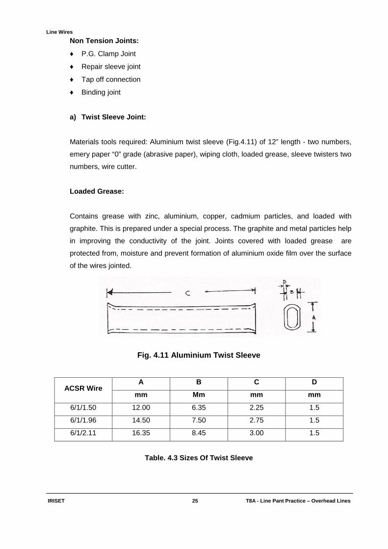
a) Twist Sleeve Joint:
Materials tools required: Aluminium twist sleeve (Fig.4.11) of 12” length - two numbers,
emery paper “0” grade (abrasive paper), wiping cloth, loaded grease, sleeve twisters two
numbers, wire cutter.
Loaded Grease:
Contains grease with zinc, aluminium, copper, cadmium particles, and loaded with
graphite. This is prepared under a special process. The graphite and metal particles help
in improving the conductivity of the joint. Joints covered with loaded grease are
protected from, moisture and prevent formation of aluminium oxide film over the surface
of the wires jointed.
Fig. 4.11 Aluminium Twist Sleeve
ACSR Wire A B C D
mm Mm mm mm
6/1/1.50 12.00 6.35 2.25 1.5
6/1/1.96 14.50 7.50 2.75 1.5
6/1/2.11 16.35 8.45 3.00 1.5
Table. 4.3 Sizes Of Twist Sleeve
Line Wires
IRISET 26 T8A - Line Pant Practic e – Overhead Lines
Twist Sleeves: These are oval shaped, thin, walled, large enough to slide over the
overlapped ends of ACSR conductors to be jointed.
Preparation Of ACSR Wire:
Both ACSR conductors and the accessories employed in jointing should be thoroughly
cleaned before use. The 6 aluminium wires are fanned out. The steel and aluminium
wires are gently cleaned by zero grade emery paper, to remove the impurities and oxide
film from the surfaces of wires to be jointed, Wiped with wiping cloth. Loaded grease is
applied over the surface of all the wires including the steel wire, wiped thoroughly again
with wiping cloth. Loaded grease applied again liberally. The aluminium wires are
reformed over the steel wire. The same process is repeated for the second wire to be
jointed.
Precautions:
While fanning of aluminium wires,
♦ The wires should not be bent more than 400, to avoid breaking of wires
♦ The original Helix should not be disturbed to facilitate proper reformation
♦ The impurities should be thoroughly removed by abrasing and wiping
♦ Zero grade emery paper is to be used to prevent loss of material
♦ Loaded grease should be liberally applied.
Preparation Of Sleeves: Both external and internal surfaces of the aluminium sleeves
are also cleaned with a zero grade emery paper, wiped as described in case of wires.
Loaded grease in sufficient quantity is applied.
Twist Sleeve Joint: The two ends of cleaned and greased ACSR are inserted into a
pair of cleaned and grease filled aluminium sleeve. The wires should lie side by side on
the flat side of the sleeve. The ends of wires should protrude 50 mm at both sides of
sleeves with a gap of 5 mm in between the two sleeves. The ends are held in position
with aluminium binding wire as shown in figure. One end of the sleeve is held in sleeve
twister B in such a way that 6 mm of the sleeve remains out. The other end of the
sleeve is similarly held in a sleeve twister A.

Line Wires
IRISET 27 T8A - Line Pant Practic e – Overhead Lines
Fig. 4.12 ACSR Wires Inserted Into Sleeves
Sleeve Twister: Consists of two rods joined together by means of a screw. There is a
slot in between to take the twisting sleeve as shown in the figure.
Fig. 4.13. ACSR Sleeve Twister
The sleeve twister A is held firmly on a suitable support. 6 half turns are given by turning
sleeve twister B, with following precautions and sequences:
♦ Direction of the twist shall be opposite to the stranding lay.
♦ Twisting should be steady, slow, with uniform speed.
♦ Jerks are to be avoided.
♦ Twisting shall proceed in stages of half turns extending over 10 seconds.
♦ The next half twist should be at least after 5 seconds
♦ Precautions should be taken to avoid bending of the sleeve joint.

Line Wires
IRISET 28 T8A - Line Pant Practic e – Overhead Lines
The second sleeve is also to be twisted similarly. The binding wires on the two conductors
are to be removed and the fine ends are to be trimmed leaving 5 mm protruding out of the
sleeves. The strands of the protruding portion are to be fanned out. Loaded grease applied
on the ends and in between sleeves. Finished joint is as shown in figure
Fig. 4.14 Finished Joint
b) Compression Sleeve joints:
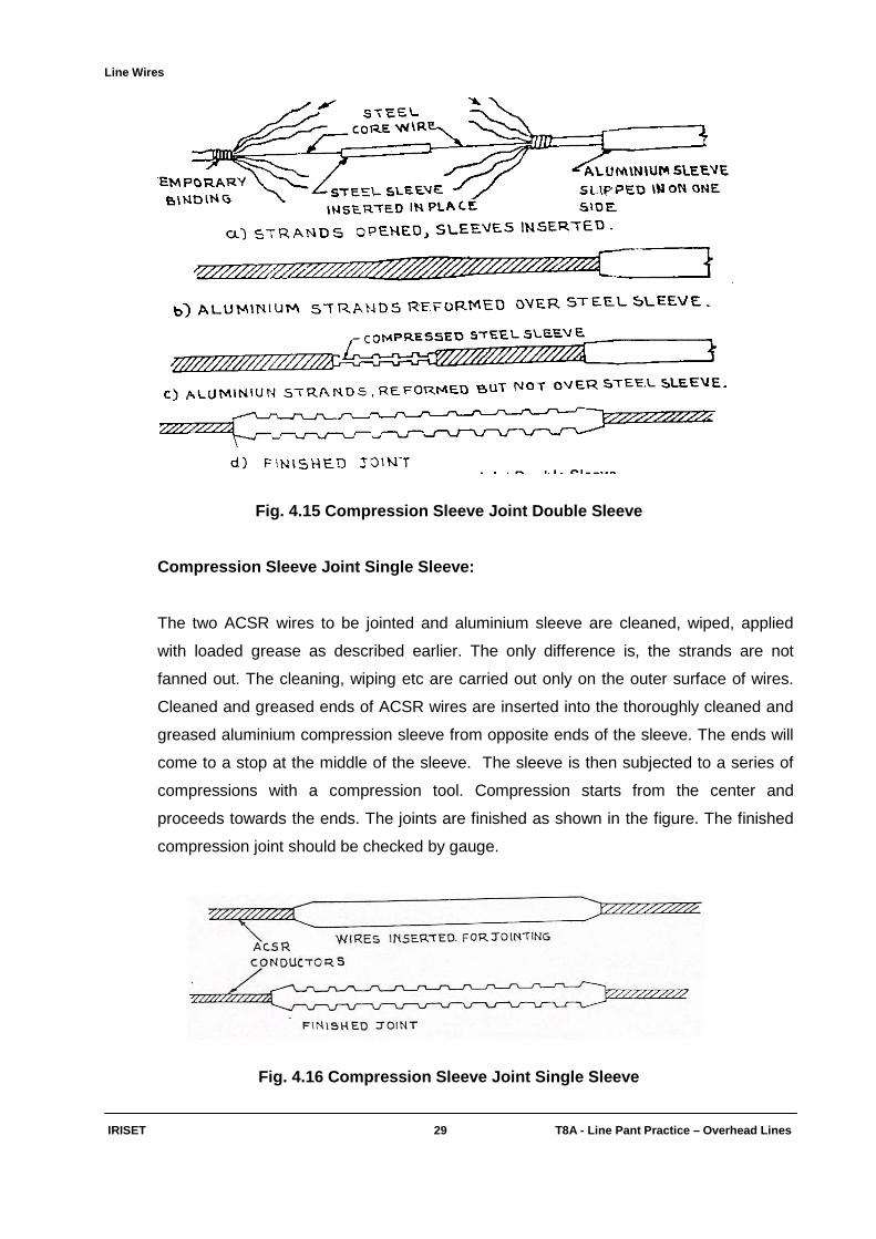
Compression Sleeve Joint Double Sleeve:
Materials tools required: One aluminium compression outer sleeve, One inner steel sleeve,
emery paper “0” grade (abrasive paper), wiping cloth, loaded grease, Hydraulic compression
tool or hand compression tool, wire cutter. The aluminium strands are fanned out, all strands
including sleeve strand are cleaned, wiped, applied with loaded grease as described in twist
sleeve joint. The compression sleeve both aluminium and steel are also cleaned, wiped,
applied with loaded grease as done for twist sleeve. The aluminium sleeve is slipped on one
of the conductors. The steel strands of the wires to be jointed are inserted into the steel
sleeve from opposite ends to meet approximately at the center. The steel sleeve is
compressed with the compression tool. Now aluminium strands are to be reformed over the
steel sleeve. But this creates a budging over the steel sleeve and prevents sliding of the
aluminium sleeve over steel sleeve as shown in figure. To avoid this, the aluminium strands
are cut on both side wires to the extent of the length covered by the steel sleeve before
reforming over the steel sleeve and then reformed. The aluminium sleeve is slided over the
steel sleeve and centered over the steel sleeve. Aluminium is thereafter compressed with a
compression tool. While using compression tool, the compressions should be carried out at
an interval of 3mm. To prevent opening out of the strands other than actually required,
aluminium binding wires may be used to hold the strands in position at a suitable distance
from the ends. ACSR in general and aluminium strands in particular need careful and gentle
handling.
Line Wires
IRISET 29 T8A - Line Pant Practic e – Overhead Lines
Fig. 4.15 Compression Sleeve Joint Double Sleeve
Compression Sleeve Joint Single Sleeve:
The two ACSR wires to be jointed and aluminium sleeve are cleaned, wiped, applied
with loaded grease as described earlier. The only difference is, the strands are not
fanned out. The cleaning, wiping etc are carried out only on the outer surface of wires.
Cleaned and greased ends of ACSR wires are inserted into the thoroughly cleaned and
greased aluminium compression sleeve from opposite ends of the sleeve. The ends will
come to a stop at the middle of the sleeve. The sleeve is then subjected to a series of
compressions with a compression tool. Compression starts from the center and
proceeds towards the ends. The joints are finished as shown in the figure. The finished
compression joint should be checked by gauge.
Fig. 4.16 Compression Sleeve Joint Single Sleeve
Line Wires
IRISET 30 T8A - Line Pant Practic e – Overhead Lines
Hand Compression Tool:
This consists of two handles and a jaw with a steel head. At the end of the jaw is an
opening for accommodating the die suitable for the respective sizes of wires. After
inserting the sleeve joint inside the die, the compression tool is pressed by hand. The
pressure on the compression sleeve is sufficient to produce the compression on the
sleeve to tightly hold the wire under tension. With a series of compressions at a gap of 3
mm each the complete sleeve is compressed to complete the joint.
The checks should be made once in every 20 joi nts:
♦ If the gauge fits correctly over the hexagon compression the sleeve tool pressure is
correct.
♦ If the gauge is loose, the tool pressure is high.
♦ If the gauge is tight or does not go over the compression, the pressure is low.
♦ The tool pressure can be corrected, by a screw, provided on the compression tool.
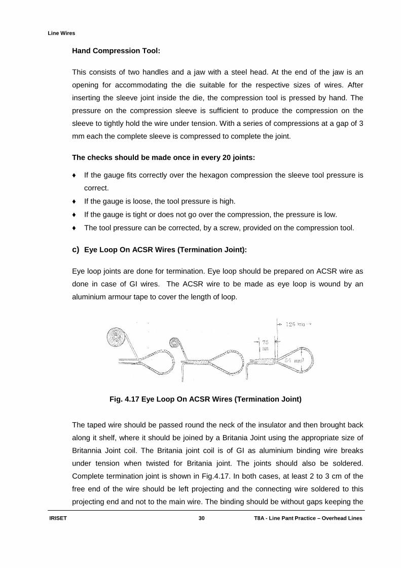
c) Eye Loop On ACSR Wires (Termination Joint):
Eye loop joints are done for termination. Eye loop should be prepared on ACSR wire as
done in case of GI wires. The ACSR wire to be made as eye loop is wound by an
aluminium armour tape to cover the length of loop.
Fig. 4.17 Eye Loop On ACSR Wires (Termination Joint)
The taped wire should be passed round the neck of the insulator and then brought back
along it shelf, where it should be joined by a Britania Joint using the appropriate size of
Britannia Joint coil. The Britania joint coil is of GI as aluminium binding wire breaks
under tension when twisted for Britania joint. The joints should also be soldered.
Complete termination joint is shown in Fig.4.17. In both cases, at least 2 to 3 cm of the
free end of the wire should be left projecting and the connecting wire soldered to this
projecting end and not to the main wire. The binding should be without gaps keeping the

Line Wires
IRISET 31 T8A - Line Pant Practic e – Overhead Lines
binding directions the same as that of the armour tape. The outer end of the GI binding
wire is finally given three turns over the armour tape on the span wire. On account of
using dissimilar metals i.e., iron over aluminium chances of corrosion exist. A coat of
loaded grease of minimum thickness 3 mm should, therefore, be applied over the
binding wire. Both ends of the joints should also be packed with grease.
(d) Pot Head Joint With ACSR: The over head bare wires of aluminium are jointed with insulated copper wires, which is
a bimetallic joint and prone for faster corrosion. To protect the joint from corrosion, the
pot on the head of the insulator is filled up with wax such that the joint does not come
into contact with moisture or moistured air.
e) P.G. (Parallel Groove) Clamp Joint (Fig. 4.18): P.G. Clamps:
Fig. 4.18 PG Clamp Joint
These clamps are used for jointing the two ends of ACSR wires. This is a non tension
joint, as the wires to be jointed are terminated on the insulators and the extended ends
of the terminated wires are only jointed through PG clamp.
The clamp consists of two aluminium alloy halves with grooves on both sides to take the
conductors and have two galvanized steel bolts to tighten them together. Spring washers
should be used with the bolts.
Line Wires
IRISET 32 T8A - Line Pant Practic e – Overhead Lines
PG clamp joint provides convenience for isolation of faulty section in case failures, but
by itself can become a source of failure if not maintained properly. The ACSR wires are
cleaned on the outer surface with zero grade emery paper, wiped, applied with loaded
grease as described earlier. Each half of the clamp contains two grooves. These clamp
halves are thoroughly cleaned, wiped, and applied with loaded grease. The cleaned and
greased ends of ACSR are placed in the two grooves of one clamp from the opposite
sides.
The second half is placed on the first half up side down to cover the first half, in a way
that the ACSR wire ends are positioned in the grooves of the second half also. The bolts
and spring washer assembly is fitted and tightened to hold the wire ends. The excess
grease is removed. The ends of the wire should protrude about 5 mm and the strands
should be fanned out. The joint may be sealed with additional application of loaded
grease. It should be ensured that no water can collect in the gaps and that the grease
sealing is perfect.
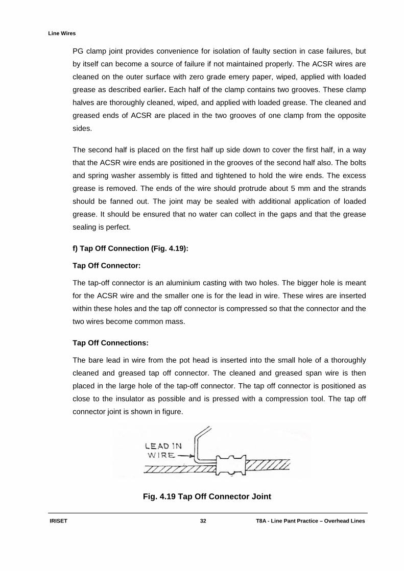
f) Tap Off Connection (Fig. 4.19): Tap Off Connector: The tap-off connector is an aluminium casting with two holes. The bigger hole is meant
for the ACSR wire and the smaller one is for the lead in wire. These wires are inserted
within these holes and the tap off connector is compressed so that the connector and the
two wires become common mass.
Tap Off Connections: The bare lead in wire from the pot head is inserted into the small hole of a thoroughly
cleaned and greased tap off connector. The cleaned and greased span wire is then
placed in the large hole of the tap-off connector. The tap off connector is positioned as
close to the insulator as possible and is pressed with a compression tool. The tap off
connector joint is shown in figure.
Fig. 4.19 Tap Off Connector Joint

Line Wires
IRISET 33 T8A - Line Pant Practic e – Overhead Lines
g) Repair Sleeve Joint (Fig. 4.20):
A non tension joint as the joint is performed on a through wire but not used for jointing to
end of wire. Repair Sleeves are for the reinforcement of ACSR wires, which have
sustained a damage causing a few of the aluminium strands to be damaged or broken
but not to the extent where the conductor has to be cut and spliced with a tension joint
Fig. 4.20 Repair Sleeve
The sleeves are of swedge type and consist of two parts, 'body' and 'keeper' both made
of aluminium. Swedge and the die made of steel are used for jointing such sleeves by
compression.The thoroughly cleaned, greased repair sleeve is placed in position on
thoroughly cleaned, greased damaged portion of the ACSR wire. Thereafter the repair
sleeve is riveted or pressed in position with a suitable swedge and die set.
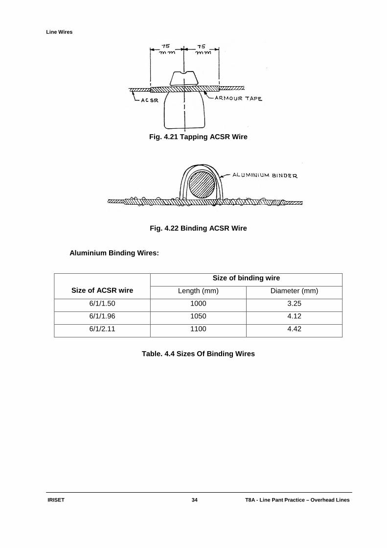
h) Binding:
The binding is done as explained in case of GI wire, but before binding the wire to the
insulator, an aluminium armour tape is wound around the ACSR wire to the length to be
covered under binding. Aluminium binding wire is used. The joint is as shown in Fig.
4.21 & 4.22
Line Wires
IRISET 34 T8A - Line Pant Practic e – Overhead Lines
Fig. 4.21 Tapping ACSR Wire
Fig. 4.22 Binding ACSR Wire
Aluminium Binding Wires:
Size of ACSR wire
Size of binding wire
Length (mm) Diameter (mm)
6/1/1.50 1000 3.25
6/1/1.96 1050 4.12
6/1/2.11 1100 4.42
Table. 4.4 Sizes Of Binding Wires
Line Wires
IRISET 34(i) T8A - Line Pant Practic e – Overhead Lines
Objective: Fill up the blanks with suitable words: 1) dB loss of 6/1/1.5 mm ACSR line wire /Km is __________ dB.
2) Loop resistance of 6/1/1.5 mm ACSR line wire/Km is __________Ω.
3) 3.55 mm Dia G.I wire is used for ______________ circuit.
4) Twist sleeve joint is done for ________________ wire.
5) Short swan neck stalks are used for terminating line wires on __________.
6) BAT is used for terminating line wires at _________________.
7) Compression sleeve joint comes under _________________joint.
8) Tap Off connector is used for jointing two _____________wires. Subjective: 1) What are the types of line wires used in Railway Telecommunications? Explain them briefly
and mention their uses?
2) List out the advantages of ACSR wire?
3) Write short notes on the following?
a) Twist joint b) Brittaniya joint c) Termination joint d) Tap-off connector e) Bind on ACSR wires f) P.G. Clamp g) Repair sleeve
4) List out the tension joints on ACSR wires? Write the procedure of making Twist sleeve
joint?
5) What is the purpose of “Eye Loop” on ACSR wire? Explain the procedure of making it with figure?
Stays
IRISET 35 T8A - Line Pant Practic e – Overhead Lines
CHAPTER 5
STAYS
5.0. Introduction:
Staying is generally the cheapest and simplest means of strengthening an existing single
post. If a post is subjected to unbalanced forces (say wind, or Line wires) the post will
bend down to one side. Stays are provided to counteract these unequal forces.. The
different types of stays are shown in the figure and how and where they are provided is
given below in table 5.1
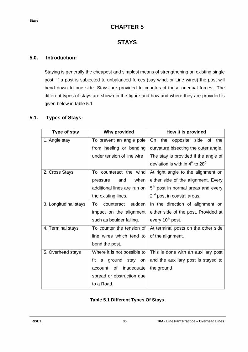
5.1. Types of Stays:
Type of stay Why provided How it is provided
1. Angle stay To prevent an angle pole
from heeling or bending
under tension of line wire
On the opposite side of the
curvature bisecting the outer angle.
The stay is provided if the angle of
deviation is with in 40 to 280
2. Cross Stays To counteract the wind
pressure and when
additional lines are run on
the existing lines.
At right angle to the alignment on
either side of the alignment. Every
5th post in normal areas and every
2nd post in coastal areas.
3. Longitudinal stays To counteract sudden
impact on the alignment
such as boulder falling.
In the direction of alignment on
either side of the post. Provided at
every 10th post.
4. Terminal stays To counter the tension of
line wires which tend to
bend the post.
At terminal posts on the other side
of the alignment.
5. Overhead stays Where it is not possible to
fit a ground stay on
account of inadequate
spread or obstruction due
to a Road.
This is done with an auxiliary post
and the auxiliary post is stayed to
the ground
Table 5.1 Different Types Of Stays
Stays
IRISET 36 T8A - Line Pant Practic e – Overhead Lines
When one stay is not sufficient to take the load two stays are fixed at different points on
the pole to distribute the forces, they can be fixed on one stay rod of sufficient strength
such as on a mast anchor or screw pile. Such an arrangement is known as V stay and
used for heavy line terminals.
5.2. Components of a stay:
Anchor: The common type of anchor in the use is called Mushroom anchor. It looks like a cast
iron pan. It should withstand a load of at least 2250 Kg. without any sign of cracking. A
protective coating of Tar is given.
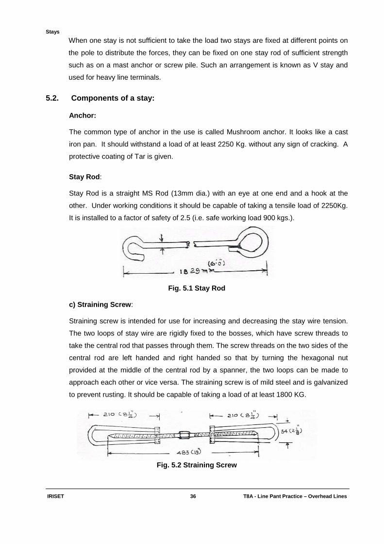
Stay Rod : Stay Rod is a straight MS Rod (13mm dia.) with an eye at one end and a hook at the
other. Under working conditions it should be capable of taking a tensile load of 2250Kg.
It is installed to a factor of safety of 2.5 (i.e. safe working load 900 kgs.).
Fig. 5.1 Stay Rod
c) Straining Screw : Straining screw is intended for use for increasing and decreasing the stay wire tension.
The two loops of stay wire are rigidly fixed to the bosses, which have screw threads to
take the central rod that passes through them. The screw threads on the two sides of the
central rod are left handed and right handed so that by turning the hexagonal nut
provided at the middle of the central rod by a spanner, the two loops can be made to
approach each other or vice versa. The straining screw is of mild steel and is galvanized
to prevent rusting. It should be capable of taking a load of at least 1800 KG.
Fig. 5.2 Straining Screw

Stays
IRISET 37 T8A - Line Pant Practic e – Overhead Lines
Stay Wire:
Stay wire should normally consist of seven strands of commercial quality iron wire (5
SWG). The grade and breaking load of various wires are shown:
Grade No.of strands. Diameter of Strands Breaking load strands.
III 7 2.00 2750
III 7 2.50 4500
III 7 3.15 7000
Table 5.2 Grade & Breaking Load Of Different stay W ires
Thimbles:
Fig. 5.3 Thimbles
At heavy line terminals and masts it is necessary to protect the stay wire from chafing.
Galvanization of eye loops of stay wire wears away due to stay wire movements and this
causes rusting and consequently weakens the stay wire. Thimbles are provided to bear
against the attachment and it will form the inner lining for the eye of the stay wire.
Stay Shackles (Fig. 5.4):
Stay Shackles are galvanized U-shaped mild steel links, having eyes at the open ends
through which a galvanized MS Hex head bolt should pass. They are normally available
in four sizes, viz., 12mm, 16mm, 19mm and 22mm, which represent the diameter of the
mild steel rods from which they are made.
Fig.5.4.Stay Shackels

Stays
IRISET 38 T8A - Line Pant Practic e – Overhead Lines
Stay Attachment :
Fig. 5.5 Stay Attachment
Stay attachment is a piece of galvanized mild steel angle of 50mmX50mm section one
end of which is shaped in the form of a hook, the other end has an elliptic slot. The
horizontal side has a clear hole for the insulator stalk to pass through. Wherever the
spread of an angle stay is restricted, this attachment is fitted to the channel iron bracket
of which it forms an extension piece. By its use, the possibility of a line wire coming into
intermittent contact with the angle stay is eliminated.
5.3. Strutting And Trussing Of Posts:
5.3.1 Strutting:
In congested area, where posts have to be erected at severe angles and it may not be
possible always to provide either the ordinary angle stay or stay to an auxiliary post due
to obstructions. Similarly, fitting stays to a terminal post may not be possible at times. In
such cases, strutting the post is the only way to strengthen it against the lateral loads.
Fig. 5.6 Direction In Which Stay & Strut Are Fitted
Stays
IRISET 39 T8A - Line Pant Practic e – Overhead Lines
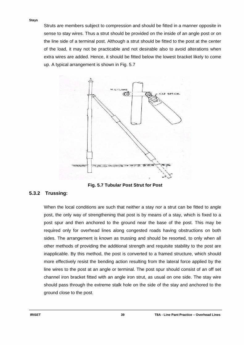
Struts are members subject to compression and should be fitted in a manner opposite in
sense to stay wires. Thus a strut should be provided on the inside of an angle post or on
the line side of a terminal post. Although a strut should be fitted to the post at the center
of the load, it may not be practicable and not desirable also to avoid alterations when
extra wires are added. Hence, it should be fitted below the lowest bracket likely to come
up. A typical arrangement is shown in Fig. 5.7
Fig. 5.7 Tubular Post Strut for Post
5.3.2 Trussing:
When the local conditions are such that neither a stay nor a strut can be fitted to angle
post, the only way of strengthening that post is by means of a stay, which is fixed to a
post spur and then anchored to the ground near the base of the post. This may be
required only for overhead lines along congested roads having obstructions on both
sides. The arrangement is known as trussing and should be resorted, to only when all
other methods of providing the additional strength and requisite stability to the post are
inapplicable. By this method, the post is converted to a framed structure, which should
more effectively resist the bending action resulting from the lateral force applied by the
line wires to the post at an angle or terminal. The post spur should consist of an off set
channel iron bracket fitted with an angle iron strut, as usual on one side. The stay wire
should pass through the extreme stalk hole on the side of the stay and anchored to the
ground close to the post.

Stays
IRISET 40 T8A - Line Pant Practic e – Overhead Lines
Fig. 5.8 Trussing
5.4 The basic requirements of staying:
A single stay should be attached to that point on the pole at which the resultant force,
due to the pull of the line wires acts. Attached at any other points, the stay would tend to
bend the pole.The wider the spread of a stay, the greater is its stability. On the other
hand, longer stays gives rise to difficulties of obstruction etc. The shorter the spread, the
greater is the vertical loading on the pole and hence, the greater the buckling stress to
which the pole is subjected.No stay need be fitted at an angle post, if the angle of
deviation is 40 or less, because the stress on insulators is so little that the stay is likely to
work loss and foul with line wires. For carrier lines, however, a pair of cross stays should
be fitted in such cases.On important routes, cross stays should be fitted at every fifth
post, unless the loading demands cross staying every or every alternate post.A stay
should be installed in such a manner that its tension would act directly against, and
along the same line as that of the resultant pull of the line wires. Assembly and
installation the components of a stay should be such that it would not result in any
appreciable yielding of the stay as whole, while on load.
Stays
IRISET 41 T8A - Line Pant Practic e – Overhead Lines
5.5 Preparations And Fitting Of Stays:
Proper attention should be paid to the marking and setting of stays in order to ensure the
safety of a line. Terminal stays should be installed on the side of the post opposite to the
line wires and must be directly in alignment with the route. Such alignment should be
obtained by sighting between the terminal and the next pole in the alignment, allowance
being made for the diameter of the pole.
5.6 Provision Of Stay At Angle Posts Or Terminal P osts:
At angles and terminals, the straining screws should be fitted at the top of the stay. This
will avoid the possibility of the poles heeling over, due to the tampering by unauthorized
persons. In case of frequent tampering by unauthorized persons, all straining screws
may be fitted at the tops of stays. For a single post, the point of application of a stay
should be somewhat higher or at the centre of the load on it, the latter should be the
case for all terminal stays. As, however, cross and angle (at small angles) stays are
liable to cause faults, staying of very small angles i.e. less than 40, should not be
allowed. The manner of attaching the terminal and angle stays to posts is detailed
below.
5.6.1 Angle Stays:
Rail posts (without ties and struts)- The stay is to be attached below the lowest bracket
likely to be fitted. A hole should be bored in the web and the end of the stay wire passed
through it and finished off.
Single rail post with ties and struts - A stay shackle and a stay attachment should be
used in the manner shown in Fig. 5.9. For a severe angle, a third stay should be fitted
direct to the pole below the lowest bracket.
Coupled Post - Stay Shackle and stay attachment should be used for this purpose in the
manner shown in Fig. 5.10

Stays
IRISET 42 T8A - Line Pant Practic e – Overhead Lines
Fig. 5.9 Angle Stays
5.6.2 Cross Stays:
The Cross stays should be fitted by wire collars direct to the post, immediately below the
lowest bracket as shown in Fig. 5.12 (a) & (b).
5.6.3 Terminal Stays:
The stay should be fixed direct to the post with wire collar, the gauge and number of
turns being the same as those in stay wire itself. The wire collars should be fitted
immediately above the bracket as shown in Fig. 5.11. For coupled post terminals, the
number of stays should be divided equally between the two posts. At rail terminal posts,
the stay should be fitted to holes drilled through the web.
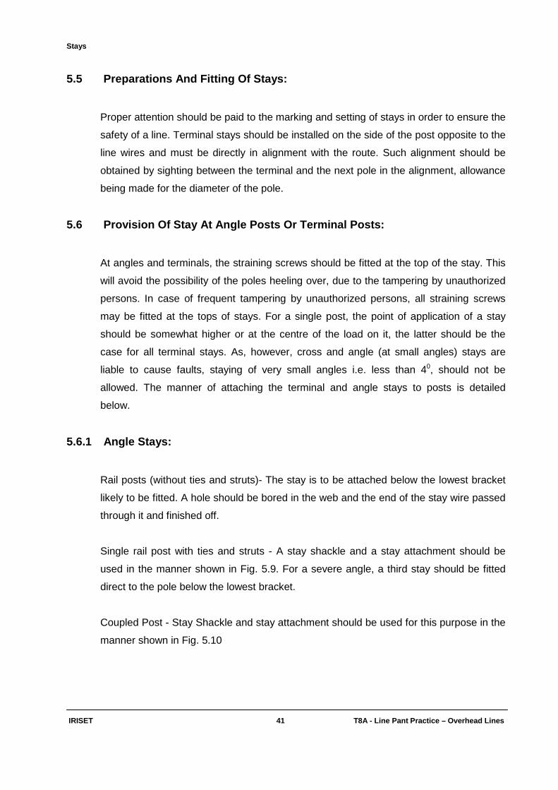
5.6.4 Auxiliary Post:
The stay should be fastened to a stay shackle at the centre of the bracket formation and
a straining screw fitted up as illustrated in Fig. 5.12(c). The auxiliary post itself should be
erected with a slight lean against the pull of the horizontal stay and should be fitted with
a lightening spike.

Stays
IRISET 43 T8A - Line Pant Practic e – Overhead Lines
Fig. 5.12 (a) Cross Stays Using Wire Collar & (b) U sing Stay Clamp
Stays
IRISET 44 T8A - Line Pant Practic e – Overhead Lines
Fig. 5.12 (c) Stays To Auxiliary Post
Stays
IRISET 44(i) T8A - Line Pant Practic e – Overhead Lines
Objective: Fill up the blanks with suitable words: 1) Stays are provided to counteract ________________ forces.
2) Auxiliary post is required for ________________stay.
3) Straining screw is for adjusting the _____________ of stay.
4) Trussing is one type of ________.
5) The Overhead stay is fitted to __________________________.
6) The Cross stay is provided at _________________________.
7) Cross stays are provided on ______________ post. Subjective: 1) What is the main purpose of ‘Stay’? What are the different types of stays provided on
overhead alignment? Why and how they are provided?
2) List out the components of stay? Write their purpose? 3) Write short notes on the following?
a) Strutting b) Trussing c) Stay rod d) Stay wire
Periodical Maintenance & Inspection of Lines
IRISET 45 T8A - Line Pant Practic e – Overhead Lines
CHAPTER 6
PERIODICAL MAINTENANCE AND INSPECTION OF LINES
6.1 Maintenance:
A high standard of efficiency in the telecommunication service demands amongst other
things, that all minor defects and faults are detected and removed expeditiously. Even
slight defects, which may appear to be negligible, if allowed to persist, may seriously
affect working in the long run and it may become very difficult to trace and clear a large
number of these minor defects at a later stage. Periodical maintenance is intended to
prevent accumulating of these individually insignificant, but collectively significant
defects over too long a period. The defects may have been left at the time of the original
construction, or have arisen subsequently due to exposure to the elements, stress of
weather etc. and may be attributable to either the supports or the line wires. The lines
should, therefore, be inspected periodically and the requirements estimated well in
advance of the actual time of the year, considered as suitable for maintenance work.
6.2 Periodical maintenance:
The following points should be taken into consideration:
• Ensuring adequate strength, stability and safety for the poles and fittings.
• Preventing deterioration of the line insulation.
• Maintaining the line resistance of each wire within limits.
• Reducing the possibility of line wire coming into contact with neighboring wire or
fittings.
• Restricting corrosion in humid and coastal areas and replacing badly corroded wire
or fittings.
Periodical Maintenance & Inspection of Lines
IRISET 46 T8A - Line Pant Practic e – Overhead Lines
6.3 Defects to which particular attention should be paid:
A. Post:
1. On dangerous ground
2. Inadequate headway at railway crossings
3. Terminating arrangements unsatisfactory
4. Posts corroded
5. Posts bent or heeling over.
6. Posts sinking
7. Bands of posts corroded
8. Sockets broken
9. Power line crossings not properly guarded.
B. Brackets and Stay Material:
1. Ties and struts missing.
2. Stays not tightened
3. Stays wrongly attached
4. Brackets crooked
5. No lightning spikes or caps.
6. Stays loose, broken or missing.
7. Ungalvanized fittings.
8. Stays require protection from cart tracks/roads.
C. Insulators:
1. Insulator dirty, broken or cracked
2. Ant's nests on insulators
3. Insulator off bracket
4. Pothead insulators not filled
5. Binders broken, rusty, or loose
6. Insulator not properly screwed down.
7. Crow nests
Periodical Maintenance & Inspection of Lines
IRISET 47 T8A - Line Pant Practic e – Overhead Lines
D. Wires:
1. Wires out of level
2. Wires sagging
3. Inadequate separation between wires.
4. Excessive length of spans
5. Wires broken.
6. Wires corroded
7. In correct transposition of wires.
8. Inadequate spacing between wires at transposition points.
9. Wire joints corroded.
10. Cloth, kites strings etc. on wires.
11. Wires tied down to insulators.
E. General:
1. Creeper on stay, post or wire.
2. Vegetation touching wires.
3. Vegetation growing under wires.
4. Trees dangerously near which require to be cut
5. Headway at road crossings inadequate
6. Branches or twigs on wires.
While removing these defects, the following standard methods should be strictly
followed. The minor defects, if any, on original construction should also be rectified as
far as possible in the course of the periodical maintenance.
1. The safety of a pole may be endangered with the passage of time, the soil may be
eroded, the ground may sink or massive earth drift may take place. All posts which are
not firmly embedded, perpendicular and in alignment should be dealt with in the manner
detailed below. The soil all round the post should be loosened to the extent necessary
and, if required, the post may be dug up completely, refilled and re-rammed. No attempt
should be made either to straighten a post or to set it back into the alignment with out
putting the line wires in the top grooves of the insulators as a temporary measure,
otherwise the post may get bent.

Periodical Maintenance & Inspection of Lines
IRISET 48 T8A - Line Pant Practic e – Overhead Lines
2. Old posts should be examined carefully for loss of strength, blisters, and cracks do not
always indicate that a post in service should be condemned as weak. Even posts having
openings along the riveted seem 3 to 15 cm (1" - 6") long and 6mm wide, with relatively
good portions in between need not necessarily be replaced immediately. If strengthening
of such poles is considered necessary, cross stays should be fitted.
3. The bases of all posts should be cleared, the lower tube portion and the mounds are
dressed with the object of preventing corrosion of the lower tube. The exposed portion of
the socket and half of the lower band should be tarred for this purpose.
4. Even galvanized line materials corrode rapidly in the salt laden humid atmosphere of
the seacoast. If, in addition, there is general abrasion due to sandstorms, the whole of
the posts and fittings should be painted with coal tar. The tarring operations should be
conducted in dry whether in the open. The mixture should be applied hot, preferably
when the line is also fairly hot in the sun.
5. All stays should be tightened up, by screwing the straining screws unless they have
reached the limit of their threads. In such cases, the stay wire should be shortened and
the straining screw opened out to the maximum. At angle or terminal posts, before the
straining screw is removed, a temporary rope stay should be used to take the load. The
threaded portion of the straining screw should be oiled liberally and the soil around the
stay rod dug for a few inches in order to check up that the rod has not lost its strength
due to corrosion.
6. All brackets should be put at right angles to the alignment, properly spaced, and
straightened wherever called for. If ties and struts are in use, any incorrect sizes should
be replaced by the proper sizes, specially at angles and terminals. All bolts and nuts
should be oiled and tightened.
7. A good insulator may cause low insulation when dirt accumulates on it. The line
insulators should, therefore, be cleaned thoroughly at least once a year and, if
necessary more frequently. After proper cleaning of insulators, the line insulation is
restored to a higher figure. All cracked and broken insulators, should be replaced by new
ones.

Periodical Maintenance & Inspection of Lines
IRISET 49 T8A - Line Pant Practic e – Overhead Lines
8. All joints at terminals should be closely inspected and those which are corroded
should be remade. Joints in spans do not normally require attention, but in case "high
resistance" is reported by the testing officer, they should be checked by an Ohm-meter.
At terminals, the jumper wires should be checked for being tight and continuous. All
corroded binders should be removed and the insulators rebound after cleaning, this will
prevent corrosion and consequent breakage of the line wires in the immediate
neighborhood.
9. Old binders, Brittania Joint Coils, loops etc. are potential causes of line interruptions,
they should therefore, be collected and buried. Wherever interruptions are caused by
fencing wire, birds nest etc. special arrangements should be made for frequent clean-up
of the affected areas, in addition to the routine patrol by the line staff.
10. Slack line wires being out of level, cause contact faults. They should be re-leveled,
ensuring that, at the normal level, they have the proper tension. Wires get out of level
mostly during interruption repairs due to change in their lengths.
11. Slack jumpers should be examined carefully for fault liability and trimmed and
soldered wherever necessary.
12. A thorough clearance of the jungle and vegetation on both sides of the line is
necessary, the extent of such clearance would, however, depend upon the importance of
the alignment, how fast the jungle grows and how frequently it is necessary to undertake
this job. Normally, it should be sufficient if every thing growing within 4 meters of each
side is completely removed periodically.
13. The maintenance work done should preferably be recorded every month on a map of
the section, which may be drawn on ordinary foolscap paper. Every year, a fresh map
should be prepared. The charts should give a clear picture of the work done in each
year, and it, therefore, can form the basis on which the maintenance programme for the
ensuing year can be drawn up.
6.4. Special maintenance :
At the time of natural calamities like cyclones, breeches etc. there will be drastic
destructions may take place for the overhead alignment. It requires complete
construction practice as new alignment.
Periodical Maintenance & Inspection of Lines
IRISET 50 T8A - Line Pant Practic e – Overhead Lines
6.5 Digging Holes :
Digging of holes may be undertaken after the marking of the hole positions for posts
and stays are completed. Where the soil is soft and is comparatively free from rocks and
stones, earth augers may be used for digging holes for erection of posts not fitted with
base plates. Where use of earth augers is not suitable, the hole should be dug by means
of pickaxes, powrahs and crow bars.
Soil: In soft or loose soil special protection arrangements should be provided to retain
the post in position. Posts shall be erected on raised concrete foundations if the area
gets periodically inundated or remains water logged. In black cotton soil, the foundation
should be taken down below till better soil is reached.
Holes for posts : The holes for the posts should be vertical. But for facility of erection, a
slope may be made out on one side longitudinal to the alignment. Depth of hole may be
from 1/6th of the post height or 1.5 meters which ever is higher depending upon length of
post and soil condition.
Holes for Stays : The holes for the stays should be big enough so as to allow anchor to
be placed properly in position. Narrow groove shall be made for the stay rod. The stay
rod when placed in position should be clear of all obstructions. In ordinary soils the depth
of stay hole should be 1 meter but in black cotton and loose soils the depth should be
increased.
6.6 Fittings :
The fitting party may fit cross arms, braces, etc., on the posts before their erection.
Fitting may be made ahead and independent of digging. Stalks, insulators, stays, etc.,
are to be fitted after the erection of posts.
Fitting up coupled posts : Where coupled posts are to be erected, the posts should be
coupled rigidly by fitting horizontal bracings first and later on cross bracings.
Fitting Cross Arms : The cross arms are fitted with 300 mm spacing between them
generally for main line system, however, the spacing between the first and second cross
arms is 600mm in case the alignment is to carry carrier circuits. The first cross arm is
kept 50mm below the top of the post. Wherever a top insulator is proposed to be used,
this distance should be increased to 100mm. After fitting the cross arms on the posts,
they should be checked that they lie in the same plane.

Periodical Maintenance & Inspection of Lines
IRISET 51 T8A - Line Pant Practic e – Overhead Lines
Fitting Ties: Main line system should have ties whenever the alignment carries two or
more cross arms. Local line system should have ties with 6 and 8 wire cross arms. Local
line system with 4 wire cross arm does not need ties.
Fitting struts : Struts are to be provided only where the ties have been fitted. Struts may
be provided at every third post for three cross arms, every alternate post for four cross
arms and on each post for more than four cross arms. For single rail posts, the struts are
supported on small angle irons fitted to the post by means of 'U' bolts for coupled posts,
horizontal bracings are first fitted by means of 'U' bolts before the struts can be
supported on them.
Post Top Fitting: In case of tubular posts the top of the posts must be fitted with caps
for providing insulator stalks or lightning conductors. For rail posts, top insulator
brackets or lightning conductors may be provided, as necessary. The top fitting shall be
rigid in order to provide good electrical conductivity with the post.
Base plates: Base plate should be fitted at the bottom end of the post tightly, as they
will be in accessible after they are buried.
Tarring : In highly corrosive areas a coat of tar may be applied to rail posts in such a way
that when the post is buried, 300mm of the tarred portion remains above ground level as
well as below ground level.
6.7 Tools for post erection :
Powrah : 1 No.
Crowbars : 2 Nos.
Rope 300mm cir. 25 metres to 30 metres long : 2 pieces.
Rope 60 mm cir. 4 metre long : 1 piece
Tent mallet : 1 No.
Tent pegs. : 4 Nos.
Pair of bamboo scissors (For single post) : 1 No.

Periodical Maintenance & Inspection of Lines
IRISET 52 T8A - Line Pant Practic e – Overhead Lines
6.8 Preparation for post erection:
Men should be distributed for different functions. Some men should keep the supporting
ropes around tent pegs in tension. Some other men should lift the post slightly and
position it with sole plate touching the crowbars.
Fig. 6.1 Hole For The post And For The Stay
A bamboo scissors may be placed in position to support the post. Post may be erected
slowly, stage by stage the position of the scissors shall be moved and the scissors
should continue to support the post. A bamboo scissors may be placed in position to
support the post. Post may be erected slowly, stage by stage the position of the scissors
shall be moved and the scissors should continue to support the post. The scissors
support is not necessary once the post is lifted more than half and the post may be
supported with the pulling rope. With the final pull, the base plate slides down the
crowbars and the post takes the vertical position.
The post complete with base plate and top fittings is placed on the ground. Two tent
pegs are driven in ground at right angle to the alignment at a distance of 5 to 6 metres.
The centre of one 30mm rope is fastened to the post at the junction of cross arm and
post, the ends of the rope are lopped around the tent pegs. Another 30mm rope is
fastened at the junction of cross arm and post. The free ends are taken to the opposite
side of the post. Crowbars are placed in the hole to aid sliding of the post.
Alignment of Post: The supervisor may make use of plumb to check if the post is
vertical and should verify visually if the post is properly aligned with the marking pegs
and other posts already erected.
Periodical Maintenance & Inspection of Lines
IRISET 53 T8A - Line Pant Practic e – Overhead Lines
Ramming : The post is to be secured in correct position, and the hole is to be filled with
earth 300mm thick at a time along with gravel and ballast if available. The loose earth
must be rammed properly with a rammer round the base till the entire hole is filled up.
Mounding: Except in railway colonies and station areas the base of a post should be
mounted to a height of 200mm from the ground. The diameter of the mound should be
about 1m and if practicable, stones, broken bricks and kunker should be added to the
top layers of the earth for preventing logging of water around the base of the post.
6.9 Erection of post in hole bored with the auger :
When a post without a base plate is required to be erected in a hole bored with an earth
auger, the post can be lifted up vertically and dropped into the hole. In erecting a heavier
post a crowbar is to be put into the hole, the end of the post laid up against this and the
post raised so that the end slides down the crowbar into position.
Erection of Coupled posts: While erecting the post care must be taken to erect both
the legs simultaneously. Two bamboo scissors will be required for supporting both the
legs and great care should be exercised so that the braces are not damaged. When
coupled posts without braces and coupling are being erected a horizontal brace should
be temporarily fitted near the bottom to keep the legs separated at correct spacing
during erection.
Erection of Stays: The stray consists of a stay wire connected to a straining screw, a
stay rod and an anchor. It is fixed at the post end through wire collars or suitable clamps
immediately below the place where the lowest cross arm has been fitted or will be fitted
considering future requirements.
Point of Application : On the post, the point of application of a single cross stay should
be below the last cross arm. Where a second cross stay is required, the point of
application should be below the last but one cross arm, and so on. Where cross arms
are framed with ties and struts the stays may be taken off from the end of cross arms
also. At terminals, the terminal stays should be applied immediately above the top cross
arm. If more than one stay is required the subsequent stays may be at lower levels.
Where a coupled post is used stays should be provided uniformly on both the legs.

Periodical Maintenance & Inspection of Lines
IRISET 54 T8A - Line Pant Practic e – Overhead Lines
Positioning of Straining Screw: The straining screw should be used along with
shackles and should be positioned near the lowest cross arm.
Fitting the straining Screw: Before connecting the straining screw in the stay
arrangement, the screw should be opened fully so as to allow for maximum tightening
after erection.
Fitting stay Rod with Anchor: The stay rod is provided with a hook at one end, which
should be attached to the centre bar of the anchor. The eye at the other end should be
joined to the wire of the stay.
Stay Protection: Stays planted near a road or path should be protected by slipping a
1.5m long iron galvanized tube over the stay wire, which will rest on the ground. The
base of the stay should also be protected by a mound of earth or stones.
6.10 Erection Of Line Wires And Final Adjustments:
6.10.1 Erection Of Line Wires:
Precautions:
When wires are being erected at a crossing with power wires and fittings they should be
considered as "live" and dangerous, whatever be the voltage. The usual precautions to
avoid contact, either directly or indirectly should be taken.
Rope Loop Guides: ACSR wires are to be paid out through rope loop guides to prevent
the wires scrapping against the drum flange. A short rope with a loop made at one end
may be tied to the four wire cross arm, driven in the ground, in front of each drum, for
this purpose. The rope will guide the wire and prevent the wire scrapping against the
drum flange.
Rope Heading: While removing the wire heads from the drums, it may be ensured that
there are no nails or projections inside the drum plates. Each wire may now be spliced
into a 50mm circumference up to 2 meters long. Another 50mm rope 5 meters long may
also be bound to both the ropes. The longer rope is used for pulling and ensuring that
both the wires move together. If necessary, the long rope may be tied on a piece of thick
wooden stick, which can be pulled conveniently.
Periodical Maintenance & Inspection of Lines
IRISET 55 T8A - Line Pant Practic e – Overhead Lines
6.10.2 Requirement Of Tensioning:
The erection of line wire includes the adjustment of the tension of line wire to a pre-
determined value, which takes the relevant factors (like temperature, elasticity, etc.) into
account. Lower tension causes contact faults and higher tension, undue strain. Variation
of temperature leads to variation of tension. After erecting wires on the post, wires are to
be tensioned in stages:
Initial tension generally known as Killing tension.
Final tension.
Tensioning: Pulley blocks or Winch type regulating equipment shall be used for
tensioning. The tension may be applied manually or by suspending appropriate weights.
Rope stop should be made of rope about 8 cm circumference and 1.5 meters long. A
ring may be provided at one end for convenience of connecting pulley block or a
dynamometer. The other end may be secured from opening out. The twists of the rope
stop are undone gradually and then are re-twisted around the wire, so that the wire
forms the core. The rope stop may be twisted on the wire for a length of about 50 cm.
The grip is to be sufficient and the rope stop does not slip while tension is applied to the
rope.
Tensioning over Transposition Point: While tensioning the wire, it is necessary to
avoid straining the wire through the transposition. The wires may, therefore, be pulled up
to the transposition point in the first instance and hold with rope stops at the
transposition post until the correct tension is given on spans beyond the post and then
finally bound at the transposition post.
Tensioning Lengths: The length of wire that can be pulled up in one stage may be as
much as 500m if no transposition point is involved. When wires are transposed,
tensioning is to be done between two consecutive transposition points.
6.10.3 Killing Tension:
When a new wire is tensioned just below its elastic limit, it does not regain fully its
original length on removal of the tension, it becomes permanently elongated to a small
extent. This wire generally behaves as an elastic material unless it is stressed still
further, when more permanent set occurs. In fact, the amount of permanent set varies
for different wires basing on the material. The line wires should, therefore, be made to
behave as an elastic material within the range of maximum possible tension to which it is
likely to be subjected under working conditions.
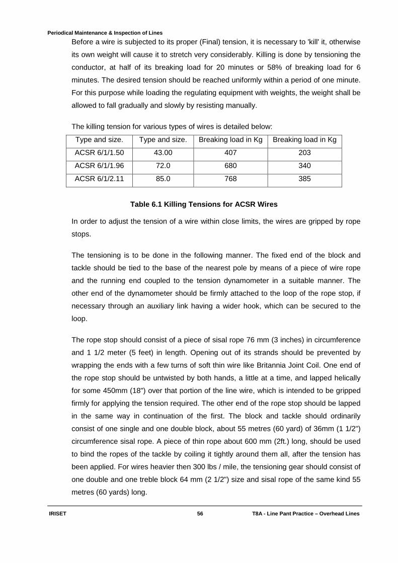
Periodical Maintenance & Inspection of Lines
IRISET 56 T8A - Line Pant Practic e – Overhead Lines
Before a wire is subjected to its proper (Final) tension, it is necessary to 'kill' it, otherwise
its own weight will cause it to stretch very considerably. Killing is done by tensioning the
conductor, at half of its breaking load for 20 minutes or 58% of breaking load for 6
minutes. The desired tension should be reached uniformly within a period of one minute.
For this purpose while loading the regulating equipment with weights, the weight shall be
allowed to fall gradually and slowly by resisting manually.
The killing tension for various types of wires is detailed below:
Type and size. Type and size. Breaking load in Kg Breaking load in Kg
ACSR 6/1/1.50 43.00 407 203
ACSR 6/1/1.96 72.0 680 340
ACSR 6/1/2.11 85.0 768 385
Table 6.1 Killing Tensions for ACSR Wires
In order to adjust the tension of a wire within close limits, the wires are gripped by rope
stops.
The tensioning is to be done in the following manner. The fixed end of the block and
tackle should be tied to the base of the nearest pole by means of a piece of wire rope
and the running end coupled to the tension dynamometer in a suitable manner. The
other end of the dynamometer should be firmly attached to the loop of the rope stop, if
necessary through an auxiliary link having a wider hook, which can be secured to the
loop.
The rope stop should consist of a piece of sisal rope 76 mm (3 inches) in circumference
and 1 1/2 meter (5 feet) in length. Opening out of its strands should be prevented by
wrapping the ends with a few turns of soft thin wire like Britannia Joint Coil. One end of
the rope stop should be untwisted by both hands, a little at a time, and lapped helically
for some 450mm (18") over that portion of the line wire, which is intended to be gripped
firmly for applying the tension required. The other end of the rope stop should be lapped
in the same way in continuation of the first. The block and tackle should ordinarily
consist of one single and one double block, about 55 metres (60 yard) of 36mm (1 1/2")
circumference sisal rope. A piece of thin rope about 600 mm (2ft.) long, should be used
to bind the ropes of the tackle by coiling it tightly around them all, after the tension has
been applied. For wires heavier then 300 lbs / mile, the tensioning gear should consist of
one double and one treble block 64 mm (2 1/2") size and sisal rope of the same kind 55
metres (60 yards) long.
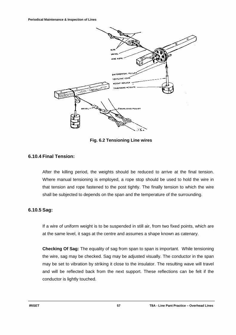
Periodical Maintenance & Inspection of Lines
IRISET 57 T8A - Line Pant Practic e – Overhead Lines
Fig. 6.2 Tensioning Line wires
6.10.4 Final Tension:
After the killing period, the weights should be reduced to arrive at the final tension.
Where manual tensioning is employed, a rope stop should be used to hold the wire in
that tension and rope fastened to the post tightly. The finally tension to which the wire
shall be subjected to depends on the span and the temperature of the surrounding.
6.10.5 Sag:
If a wire of uniform weight is to be suspended in still air, from two fixed points, which are
at the same level, it sags at the centre and assumes a shape known as catenary.
Checking Of Sag: The equality of sag from span to span is important. While tensioning
the wire, sag may be checked. Sag may be adjusted visually. The conductor in the span
may be set to vibration by striking it close to the insulator. The resulting wave will travel
and will be reflected back from the next support. These reflections can be felt if the
conductor is lightly touched.
Periodical Maintenance & Inspection of Lines
IRISET 58 T8A - Line Pant Practic e – Overhead Lines
6.10.6 Alignment with ACSR and G.I:
Recommended sizes of GI wires are mechanically weaker than recommended sizes of
ACSR wires. GI of less than 3.55mm shall not be used on main lines. Sag of ACSR is to
be so adjusted that at 300 C, the sag of ACSR is equal to sag of GI on the alignment.
6.11 Transposition:
If each telecom circuit is completely isolated from all other sources of electricity, no
potentials other than those deliberately introduced for the purpose of telecom
transmission, are present in any telecom circuit. In practice, however telecom circuits are
rarely entirely isolated, as they are in close proximity to other telecom circuits and to
other electrical circuits such as power lines. In addition they are exposed to interference
from atmospheric disturbances and radio transmission also.
All electrical circuits set up electromagnetic fields, which cause interference in the form
of cross talk and noise in neighbouring circuits.
Cross talk is the intelligible or unintelligible speech overheard on a telecom line as
induced by an adjacent telecom line. The term noise is usually applied to all other forms
of interference, which may arise from:
• An adjacent telecom line (eg. signalling pulses)
• External sources (eg: Power Lines, atmospheric disturbances, radio transmission
and electric traction system.)
6.11.1 Electromagnetic Field:
When voltage and current exist on a telecom line, "Fields" or lines of force are set up
about the wire of the line. There are two types of fields, one of which is associated with
the voltage and the other with the current. The field associated with the voltage is called
an electrostatic or electric field because it is caused by the voltage existing between -
• The two line wires
• The line wires and earth
• The line wires and nearly lines.
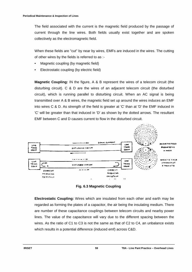
Periodical Maintenance & Inspection of Lines
IRISET 59 T8A - Line Pant Practic e – Overhead Lines
The field associated with the current is the magnetic field produced by the passage of
current through the line wires. Both fields usually exist together and are spoken
collectively as the electromagnetic field.
When these fields are "cut" by near by wires, EMFs are induced in the wires. The cutting
of other wires by the fields is referred to as :-
• Magnetic coupling (by magnetic field)
• Electrostatic coupling (by electric field)
Magnetic Coupling: IN the figure, A & B represent the wires of a telecom circuit (the
disturbing circuit). C & D are the wires of an adjacent telecom circuit (the disturbed
circuit), which is running parallel to disturbing circuit. When an AC signal is being
transmitted over A & B wires, the magnetic field set up around the wires induces an EMF
into wires C & D. As strength of the field is greater at 'C' than at 'D' the EMF induced in
'C' will be greater than that induced in 'D' as shown by the dotted arrows. The resultant
EMF between C and D causes current to flow in the disturbed circuit.
Fig. 6.3 Magnetic Coupling
Electrostatic Coupling: Wires which are insulated from each other and earth may be
regarded as forming the plates of a capacitor, the air being the insulating medium. There
are number of these capacitance couplings between telecom circuits and nearby power
lines. The value of the capacitance will vary due to the different spacing between the
wires. As the ratio of C1 to C3 is not the same as that of C2 to C4, an unbalance exists
which results in a potential difference (induced emf) across C&D.

Periodical Maintenance & Inspection of Lines
IRISET 60 T8A - Line Pant Practic e – Overhead Lines
Fig. 6.4 Electrostatic Coupling
This potential difference causes current to flow and results in cross talk in the disturbed
circuit C&D.
Combined Effects Of Magnetic And Electrostatic Coup lings:
The figures show the induced currents in the disturbed circuit due to magnetic and
electrostatic couplings respectively. The effect of these currents is to combine and
produce.
• A high level of cross talk at one end of the disturbed circuit (Near End Cross Talk)
because the currents at that end are in the same direction and are additive.
• A low level of cross talk at the other end of the disturbed circuit (Far End Cross Talk)
because the currents are in opposition and only the difference between them
produce cross talk.
Circuit Balance: Even both wires are equally spaced from a disturbing circuit, cross talk
and noise will occur in the circuit if the pair is electrically unbalanced. One wire might
have a greater resistance than the other perhaps due to a poorly made joint, or the use
of a piece of wire of slightly different gauge to repair a fault. This unbalance often
referred to as resistance unbalance. In case of overhead alignments the cross talk
reduction depends upon three main factors namely
• Wire configuration on poles
• The distance between wires of a pair
• The distance between pairs
• The frequency of current in the disturbing circuit.
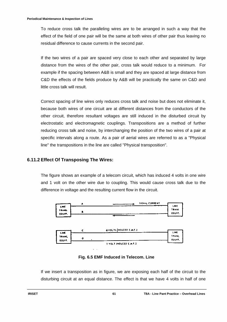
Periodical Maintenance & Inspection of Lines
IRISET 61 T8A - Line Pant Practic e – Overhead Lines
To reduce cross talk the paralleling wires are to be arranged in such a way that the
effect of the field of one pair will be the same at both wires of other pair thus leaving no
residual difference to cause currents in the second pair.
If the two wires of a pair are spaced very close to each other and separated by large
distance from the wires of the other pair, cross talk would reduce to a minimum. For
example if the spacing between A&B is small and they are spaced at large distance from
C&D the effects of the fields produce by A&B will be practically the same on C&D and
little cross talk will result.
Correct spacing of line wires only reduces cross talk and noise but does not eliminate it,
because both wires of one circuit are at different distances from the conductors of the
other circuit, therefore resultant voltages are still induced in the disturbed circuit by
electrostatic and electromagnetic couplings. Transpositions are a method of further
reducing cross talk and noise, by interchanging the position of the two wires of a pair at
specific intervals along a route. As a pair of aerial wires are referred to as a "Physical
line" the transpositions in the line are called "Physical transposition".
6.11.2 Effect Of Transposing The Wires:
The figure shows an example of a telecom circuit, which has induced 4 volts in one wire
and 1 volt on the other wire due to coupling. This would cause cross talk due to the
difference in voltage and the resulting current flow in the circuit.
Fig. 6.5 EMF Induced in Telecom. Line
If we insert a transposition as in figure, we are exposing each half of the circuit to the
disturbing circuit at an equal distance. The effect is that we have 4 volts in half of one
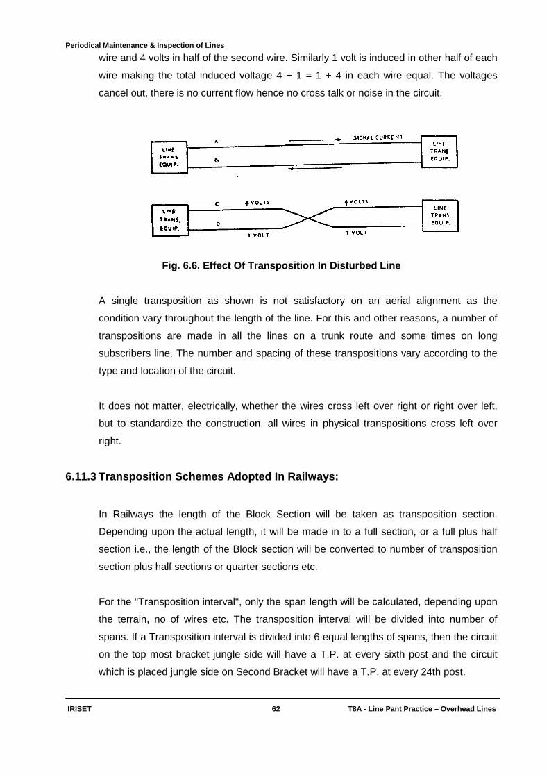
Periodical Maintenance & Inspection of Lines
IRISET 62 T8A - Line Pant Practic e – Overhead Lines
wire and 4 volts in half of the second wire. Similarly 1 volt is induced in other half of each
wire making the total induced voltage 4 + 1 = 1 + 4 in each wire equal. The voltages
cancel out, there is no current flow hence no cross talk or noise in the circuit.
Fig. 6.6. Effect Of Transposition In Disturbed Line
A single transposition as shown is not satisfactory on an aerial alignment as the
condition vary throughout the length of the line. For this and other reasons, a number of
transpositions are made in all the lines on a trunk route and some times on long
subscribers line. The number and spacing of these transpositions vary according to the
type and location of the circuit.
It does not matter, electrically, whether the wires cross left over right or right over left,
but to standardize the construction, all wires in physical transpositions cross left over
right.
6.11.3 Transposition Schemes Adopted In Railways:
In Railways the length of the Block Section will be taken as transposition section.
Depending upon the actual length, it will be made in to a full section, or a full plus half
section i.e., the length of the Block section will be converted to number of transposition
section plus half sections or quarter sections etc.
For the "Transposition interval", only the span length will be calculated, depending upon
the terrain, no of wires etc. The transposition interval will be divided into number of
spans. If a Transposition interval is divided into 6 equal lengths of spans, then the circuit
on the top most bracket jungle side will have a T.P. at every sixth post and the circuit
which is placed jungle side on Second Bracket will have a T.P. at every 24th post.

Periodical Maintenance & Inspection of Lines
IRISET 63 T8A - Line Pant Practic e – Overhead Lines
Transposition arrangement for 15 pole per km. alignment.
• Administrative Trunk Every 4th pole
• Section Control Every 7th pole
• Deputy Control Every 13th pole
• Carrier Circuits Alternative Poles
6.11.4 Definition:
• Zero Post: The beginning of the alignment is known as zero post.
• Span: The distance between two consecutive posts.
• Transposition Interval: Length of line between two consecutive transposition points.
6.12. L-14 Diagrams:
L-14 diagrams give the line details of the particular circuits on over headline alignment
showing the positions of the individual circuits in the form of drawing (charts). The
diagrams are also shows the KM No. and alignment direction with respect to the track
i.e. left or right side of the track while facing Up/Dn direction as the case may be.
The construction department prepares the diagrams after completion of construction of
the alignment, and supplied to the maintenance organization in sufficient copies.
These diagrams are provided to Guards of all trains to locate the control circuits for
connecting the PCP in the mid section during emergency for control communication with
the section controller.
The line alignment will have the following plans according the priority of the circuit.
1. On the top most bracket of the alignment, ADM circuits and Block circuits will run
along the track.
2. Middle brackets carry other lines like LC Gate etc.
3. Bottom most brackets carries section control circuits and Dy.control circuits.

Periodical Maintenance & Inspection of Lines
IRISET 64 T8A - Line Pant Practic e – Overhead Lines
STN.CODE KM.NO.130.2
ADM BLOCK
DN
LC LC
ADM BLOCK
Dy.CNL. Sec.CNL
LC LC
KM NO.127.5
Dy.CNL Sec.CNL.
UP
KM NO.121.5 STN.Code
6.7.Typical L-14 diagram
6.13 Inspection:
The inspections may be of two types -
• Preventive Patrols
• Periodical inspections.
The first type is meant for eliminating those sources of fault over which there is normally
no control and which cannot be foreseen. Such patrols should be carried out regularly by
the members of the line staff and occasionally by the supervisory staff as a measure of
check on the work of the former. The second type is restricted to the controlling and
supervisory officials and is intended to bring out the defects, which are preventable, with
full details, so as to take suitable steps to eliminate them at the earliest.

Periodical Maintenance & Inspection of Lines
IRISET 65 T8A - Line Pant Practic e – Overhead Lines
Every lineman, who has a definite section of line allotted, should regularly patrol the
same, according to the orders of the concerned officer. In course of routine patrols, the
following items of work should be carried out –
• Replacement of broken insulators and removal of cobwebs, kite strings etc.
• Removal of creepers from posts, stays etc.
• Isolated clearing and chopping of tree branches.
• Tightening or repairing of stays.
• Straightening brackets.
• Tightening guard wires.
• Examining and re-soldering suspected joints at line and office terminals.
• Other minor items of work, which may prevent a fault from developing either
intermittently or permanently.
Where the faulty condition cannot be repaired on the spot, the matter should be reported
with full details to the sectional supervisor, who will arrange to get the work done as
soon as possible.
A suitable programme should be drawn up to ensure that linemen patrol their sections as
frequently as required under the conditions prevailing locally, no two adjacent lineman,
should, however be out on patrol on the same way. While deciding the frequency of
these inspections, the officer should be guided mainly by the importance of the routes
depending upon the traffic carried and also by the climatic and physical features of the
country. The carrier routes should be patrolled by linemen once a week. Maintainer, if
any, should accompany the linemen, so that they may inspect the whole of their section
once a month.
6.14 Primary object of all inspections:
To eliminate to the utmost all interruptions, which can be classified as "preventable".
Hence, there should be effective and close control on line maintenance. All items of such
work concerning maintenance of line, for a particular period should be determined only
after careful inspection of the sections concerned and not left to the discretion of the
maintenance party, on the basis of general instructions. For this purpose, a correct
estimate of the actual amount of jungle cutting, post and wire maintenance should be
prepared only after the routes have been personally inspected by a responsible officer
about one month before the maintenance season.
Periodical Maintenance & Inspection of Lines
IRISET 66 T8A - Line Pant Practic e – Overhead Lines
It is the duty of the supervisory, executive and administrative officers to take active
interest in the condition of lines within their jurisdictions. The officers should decide the
mode of carrying out inspections by officials directly under them. However, while
traveling in connection with other duties, all officers up to the rank of supervisors should
note defects on pole routes requiring attention. It should be appreciated by all concerned
that the value of such reports is largely lost, if they are filed without proper action being
taken to remove the faults quickly. Accordingly, the higher officers should make it a
point to verify, by reference to recent reports, that all specific faults, pointed out there in
have actually been eliminated. Thereafter they should take steps to have all defects (still
continuing) promptly removed and take suitable notice of anything that points to neglect
on the part of the staff. The supervising officers should also inspect any line on which the
duration or number of interruptions is on the increase or there are reasons to believe that
the line is faulty in any other way.
The officers should inspect their lines by day train, in case of railway alignments and
submit their reports promptly, paying particular attention to the common cause of faults.
One copy of the report should be forwarded to the next higher officer for scrutiny and
record. The action taken on each defect should be noted and the reports kept pending
until all defects have been removed. The higher officer after perusal of the Inspection
Report should satisfy himself, if necessary, by personal inspection, that extensive
renewals or replacements wherever reported as urgent or essential, are actually
necessary.
In order to trace difficult types of frequent faults, officer may have to inspect a line on
foot. In such cases, he should preferably, be accompanied by the sectional lineman, who
should repair any defect that requires immediate attention.
Officers and Supervisors should inspect the main lines as frequently as circumstances
may render necessary. The higher officers should inspect such routes at least once a
year. Because of their importance, carrier routes require special attention. The Junior
Officers should inspect such routes at least once in six months and, if possible, more
frequently by the supervisors, the frequency of these inspections should be at least once
per month. The official in direct charge of line should usually inspect all lines along
railway track by train once a month, and on foot once in every three months, in case of
side lines along road, the inspection on foot should be once every three months.
Periodical Maintenance & Inspection of Lines
IRISET 67 T8A - Line Pant Practic e – Overhead Lines
6.15 Common Defects:
All inspecting officers should inspect the lines carefully for the following common defects
and make a detailed report.
A - Posts:
(1) On dangerous ground, (2) Inadequate headway,
3) Unsatisfactory terminal, (4) Corrosion,
5) Bending or healing, (6) Sinking,
(7) Corroded bands, (8) Broken sockets,
(9) Electric power line crossings - guarding arrangements,
(10) Missing of lightning spike or cap.
B - Brackets And Stay Materials:
(i) Ties and struts are not properly fitted or missing
(ii) Stays broken, loose or not properly fitted
(iii) Brackets - bent or crooked
(iv) Corroded Fittings
(v) Stay - protection required.
C - Insulators:
(i) Broken, cracked or abode of ants, insects etc.
(ii) Out off the bracket or not properly screwed down
(iii) Pot head not filled or cap broken/missing.
D - Wire:
(i) Out of level (ii) Sagging or too tight
(ii) Excessive span length (iv) Corroded wire
(v) Transpositions not proper (vi) Corroded joints
(vii) Foreign matter on wires.
Periodical Maintenance & Inspection of Lines
IRISET 68 T8A - Line Pant Practic e – Overhead Lines
E – Jungle:
(i) Creepers on stay, post or wire
(ii) Vegetation touching wires
(iii) Vegetation under wires
(iv) Trees dangerously near the line.
F - Miscellaneous:
(i) Houses, hay stacks etc. being built too close to the line
(ii) Infringement of standard dimensions laid down for lines along railway
(iii) Lines crossed by electric wire without guarding
(iv) H.T. power wires running close to departmental lines.
Periodical Maintenance & Inspection of Lines
IRISET 68(i) T8A - Line Pant Practic e – Overhead Lines
Objective: Fill up the blanks with suitable words: 1) Killing tension of ACSR 6/1/1.5 is _________ Kg.
2) Transposition arrangement for section control is at every ______pole.
3) Transposition arrangement for Deputy control is at every ________ pole.
4) The post at the beginning of the alignment is known as ______post.
5) By transposition __________ can be kept minimum. Subjective: 1) What are the points to be considered during periodical maintenance of overhead lines?
2) What is the periodical maintenance to be carried out for the following?
a) Bracket and stay material b) Line wires c) Insulators
3) Explain the following terms briefly
a) Killing tension b) Final tension c) Sag
4) What information is given by L-14 diagram? Explain with atypical L-14 diagram?
5) What inspection is to be carried out on overhead alignment? What is the work to be done in
course of routine patrols?
Protection from Power Lines & Inductive Co-ordination
IRISET 69 T8A - Line Pant Practic e – Overhead Lines
CHAPTER 7
PROTECTION FROM POWER LINES
AND INDUCTIVE CO-ORDINATION
7.1 Power Line Interference :
The telecommunication circuits are likely to be interfered from power lines due to:
• Direct contact between the power line and the telecom line
• Induction from power line due to parallelism.
7.1.1 Contact from Power Lines:
The chances of contact from power lines must be eliminated. As such contacts are likely
to be dangerous to the lives of telecommunication operators and maintenance staff.
Guarding wires may be provided on -
i) Power circuits and ii) Telecommunication circuits.
The guards should be of substantial construction and must be efficiently maintained. The
guard has to withstand conditions, which may be sufficient to break line conductors and
in addition it has to bear the weight of the conductors, which falls on it.
7.1.2 Guard wires on Power Circuits:
Usually power circuits are above the telecommunication circuits. The guard wire is
provided on power circuits in such a way, that in case a wire in the power alignment
snaps, the wire will be earthed immediately by falling on the guard wire. Guarding
arrangements may be divided into two main clauses:
• Guards for High tension power crossings
• Guards for Low tension Power crossings.
High tension power line may be considered as one on which the voltage between any
two conductors insulated from earth or between any conductor and earth is 650V or
above: low tension line is below that figure.
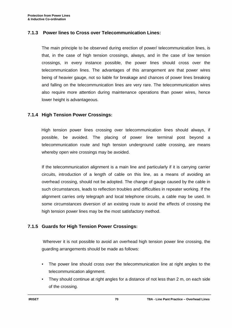
Protection from Power Lines & Inductive Co-ordination
IRISET 70 T8A - Line Pant Practic e – Overhead Lines
7.1.3 Power lines to Cross over Telecommunication Lines:
The main principle to be observed during erection of power/ telecommunication lines, is
that, in the case of high tension crossings, always, and in the case of low tension
crossings, in every instance possible, the power lines should cross over the
telecommunication lines. The advantages of this arrangement are that power wires
being of heavier gauge, not so liable for breakage and chances of power lines breaking
and falling on the telecommunication lines are very rare. The telecommunication wires
also require more attention during maintenance operations than power wires, hence
lower height is advantageous.
7.1.4 High Tension Power Crossings :
High tension power lines crossing over telecommunication lines should always, if
possible, be avoided. The placing of power line terminal post beyond a
telecommunication route and high tension underground cable crossing, are means
whereby open wire crossings may be avoided.
If the telecommunication alignment is a main line and particularly if it is carrying carrier
circuits, introduction of a length of cable on this line, as a means of avoiding an
overhead crossing, should not be adopted. The change of gauge caused by the cable in
such circumstances, leads to reflection troubles and difficulties in repeater working. If the
alignment carries only telegraph and local telephone circuits, a cable may be used. In
some circumstances diversion of an existing route to avoid the effects of crossing the
high tension power lines may be the most satisfactory method.
7.1.5 Guards for High Tension Power Crossings :
Wherever it is not possible to avoid an overhead high tension power line crossing, the
guarding arrangements should be made as follows:
• The power line should cross over the telecommunication line at right angles to the
telecommunication alignment.
• They should continue at right angles for a distance of not less than 2 m, on each side
of the crossing.
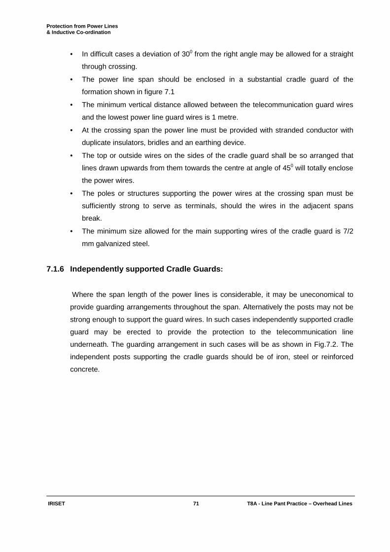
Protection from Power Lines & Inductive Co-ordination
IRISET 71 T8A - Line Pant Practic e – Overhead Lines
• In difficult cases a deviation of 300 from the right angle may be allowed for a straight
through crossing.
• The power line span should be enclosed in a substantial cradle guard of the
formation shown in figure 7.1
• The minimum vertical distance allowed between the telecommunication guard wires
and the lowest power line guard wires is 1 metre.
• At the crossing span the power line must be provided with stranded conductor with
duplicate insulators, bridles and an earthing device.
• The top or outside wires on the sides of the cradle guard shall be so arranged that
lines drawn upwards from them towards the centre at angle of 450 will totally enclose
the power wires.
• The poles or structures supporting the power wires at the crossing span must be
sufficiently strong to serve as terminals, should the wires in the adjacent spans
break.
• The minimum size allowed for the main supporting wires of the cradle guard is 7/2
mm galvanized steel.
7.1.6 Independently supported Cradle Guards :
Where the span length of the power lines is considerable, it may be uneconomical to
provide guarding arrangements throughout the span. Alternatively the posts may not be
strong enough to support the guard wires. In such cases independently supported cradle
guard may be erected to provide the protection to the telecommunication line
underneath. The guarding arrangement in such cases will be as shown in Fig.7.2. The
independent posts supporting the cradle guards should be of iron, steel or reinforced
concrete.
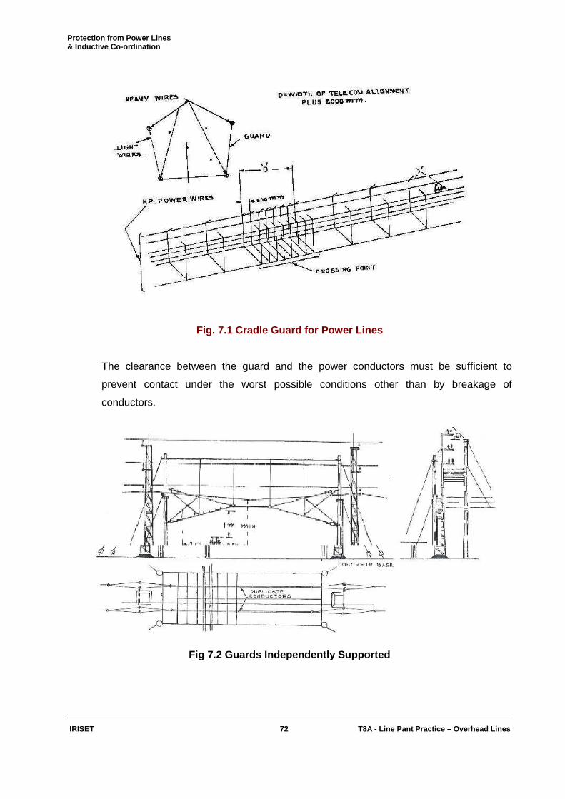
Protection from Power Lines & Inductive Co-ordination
IRISET 72 T8A - Line Pant Practic e – Overhead Lines
Fig. 7.1 Cradle Guard for Power Lines
The clearance between the guard and the power conductors must be sufficient to
prevent contact under the worst possible conditions other than by breakage of
conductors.
Fig 7.2 Guards Independently Supported
Protection from Power Lines & Inductive Co-ordination
IRISET 73 T8A - Line Pant Practic e – Overhead Lines
7.1.7 Approval of Electrical Inspector:
Since the Electrical Inspectors of the Govt., are the statutory authorities for determining
whether a guarding arrangement is satisfactory, the method of guarding the high tension
crossing may be modified with the approval of the Electrical Inspector to the Govt., if
local circumstances are such that the modification of the standard arrangement is
necessary. The Electrical Inspector's approval in writing should be obtained and
recorded in all such cases where modifications in the guarding arrangements for high
tension power crossings are introduced.
7.1.8 Guards for Low Tension Power Crossings:
Where power lines have already been erected and it subsequently becomes necessary
to put up railway telecommunication lines in close proximity to, or across, an unguarded
portion of the same, one month's notice in writing of the proposed erection should be
given to the power undertaking, so that they can arrange for the necessary guards within
a reasonable time. The Electrical Inspector to the Government should also be informed.
The best way of guarding low tension power wires, where, they cross telecommunication
wires, is to enclose the former in a cradle composed of guard wires as shown in fig. 7.3
angle iron brackets are fixed on the posts on each side of any span which crosses a
telecommunication wire. Guard wires are run from four end points A, B, C and D of the
angle iron fixture to the corresponding points of a similar fixture on the next post. At
intervals of 1 metre along the span of guard wires other cross guards are fastened
commencing at one of the top wire running round the bottom wires and finally ending up
to the other top wire, thus forming a cage round the low tension wire. With such a guard
on a low tension power line, there is no need for any other guards on the
telecommunication alignment. In cases where a cage cannot be fixed, a net guard as
shown in figure 7.4 should be fixed on the power posts underneath the low tension
wires.
Fig. 7.3 Cage Guards on LT power Lines
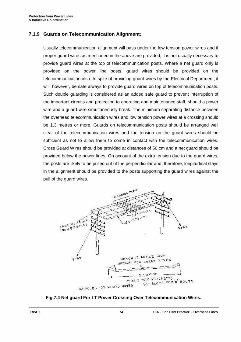
Protection from Power Lines & Inductive Co-ordination
IRISET 74 T8A - Line Pant Practic e – Overhead Lines
7.1.9 Guards on Telecommunication Alignment :
Usually telecommunication alignment will pass under the low tension power wires and if
proper guard wires as mentioned in the above are provided, it is not usually necessary to
provide guard wires at the top of telecommunication posts. Where a net guard only is
provided on the power line posts, guard wires should be provided on the
telecommunication also. In spite of providing guard wires by the Electrical Department, it
will, however, be safe always to provide guard wires on top of telecommunication posts.
Such double guarding is considered as an added safe guard to prevent interruption of
the important circuits and protection to operating and maintenance staff, should a power
wire and a guard wire simultaneously break. The minimum separating distance between
the overhead telecommunication wires and low tension power wires at a crossing should
be 1.3 metres or more. Guards on telecommunication posts should be arranged well
clear of the telecommunication wires and the tension on the guard wires should be
sufficient as not to allow them to come in contact with the telecommunication wires.
Cross Guard Wires should be provided at distances of 50 cm and a net guard should be
provided below the power lines. On account of the extra tension due to the guard wires,
the posts are likely to be pulled out of the perpendicular and, therefore, longitudinal stays
in the alignment should be provided to the posts supporting the guard wires against the
pull of the guard wires.
Fig.7.4 Net guard For LT Power Crossing Over Teleco mmunication Wires.
Protection from Power Lines & Inductive Co-ordination
IRISET 75 T8A - Line Pant Practic e – Overhead Lines
7.1.10 With these arrangements the principal points to be remembered:
i) A sufficient number of guard wires should be erected to ensure that the space between
them does not exceed 800 mm.
ii) The outside guard wires should be 200 mm beyond the outside telecommunication
wires.
iii) The guard wires should preferably be at a height of not less than 600 mm above the
telecommunication wires.
7.1.11 Earthing Guards:
It is extremely important that wherever guard wires are erected, they shall be properly
earthed. For this purpose the frame on which the guard wires are supported and the
guard wires themselves should be provided with efficient earth connections at several
points, as an unearthed guard wire may lead to dangerous conditions.
7.1.12 Guard over Electric Traction Wires :
Where telecommunication lines have crossed over direct current electric traction wires,
guard wires shall be provided to prevent the telecommunication wires from falling on the
traction wire in case of break faults. The minimum clearance between the guard wire and
the electric traction wire should be 600 mm. The arrangement of guard wires in this case
will be the same as described except that the guard wires should be erected below the
telecommunication wires preferably at a distance of 300 mm below the lowest
telecommunication wires.
7.1.13 Insulated Line Wires :
The use of insulated line wires at power crossings increases the measure of protection
from contacts with power lines. But even then the usual guarding arrangements should
be provided, as if the telecommunication wires were bare.
7.1.14 Stays:
The Stays should not be run over or under low tension power conductors, when there is
any reasonable alternative. Where such crossings are unavoidable, guarding is
necessary. Where there is danger of stay making simultaneous contact with telegraph
and low power tension conductors, a shackle insulator should be fitted in the stay wire to
isolate the portion likely to make contact with the telecommunication wires from the
portion which may make contact with the power wires. Stays should never be erected
over or near high tension wires.
Protection from Power Lines & Inductive Co-ordination
IRISET 76 T8A - Line Pant Practic e – Overhead Lines
7.2 Induction from power lines due to Parallelism:
Power lines running at close distances parallel to the telecommunication lines produce
noise and disturbance in the telecommunication circuits during normal working
conditions and the induced voltage rises dangerously in faulty conditions of the power
lines. To eliminate these effects a considerable separation between the power lines and
the telecommunication lines has to be ensured in addition to reduction of the length of
parallelism, as far as practicable.
7.2.1 Separation to avoid inductive interference :
The most effective remedy for securing freedom from inductive interference is avoidance
of close proximity between power lines and communication circuits. The minimum
separation between the circuits consistent with the requirements of construction and
maintenance for both sides of lines avoiding the effects of inductive interference in
normal conditions is given by the expression –
S = 4.4 E.L Where
S = separating distance in metres.
E = voltage between the phases of the power lines.
L = length of parallelism in Km.
7.2.2 Effects of Fault Current :
The voltage limits adopted in this country are the same as recommended by ITU Viz.,
60V for high security lines and 430V for non-high security lines. All power lines of
voltage class 33 KV and below, fall under the category of non-high security lines and
hence the prescribed limit for induced voltage is 430V. The separation between the
power and telecommunication lines should, therefore, be such that the induced voltage
does not exceed the limit prescribed. The minimum safe separation required between
the power and telecommunication lines is determined by the product of the fault current
and the length of parallelism.
Protection from Power Lines & Inductive Co-ordination
IRISET 77 T8A - Line Pant Practic e – Overhead Lines
7.2.3 Fault Current:
The fault current I is dependent on -
• Voltage class of the power line (33, 22 or 11 KV).
• Size of conductor used for the power line.
• The total capacity of the substation transformer in Mega volt amp. = K.
• The distance of the point of fault on the power line from the substation in Km = L
Assuming that a single line to ground fault occurs, the formula for calculation of the earth
current based on the principle of symmetrical components using 8% reactance for the
step down transformer, is as follows:
I = A / (B.L + 24 / K) 2 - C.L / K Where
A = 5250 for 33 KV 7875 for 22 KV and 15750 for 11 KV
Values of B and C may be obtained from the table 7.1 value of fault current I is
calculated.
Conductor Size
B C
33 KV 22 KV 11 KV 33 KV 22 KV 11 KV
0.16 cm2 - - 3.5 - - 72.0
0.19 cm2 0.348 0.784 3.14 6.06 13.5 54.5
0.26 cm2 0.300 0.676 2.72 3.81 8.54 34.4
0.39 cm2 0.260 0.586 2.34 1.96 4.5 18.0
0.48 cm2 0.246 - - 1.40 - -
0.65 cm2 0.229 - - 0.87 - -
Table 7.1 Calculation Of Fault Current – Values Of B & C
7.2.4 Minimum Permissible Separation:
The minimum permissible separation in meters can be read off directly from the graph
given at figure 7.4, against the product of fault current and length of parallelism in
Amp./Km. Separate curves have been given for soil resistivities of 5000, 10000, 20000
and 50000 Ohm / Cm3.

Protection from Power Lines & Inductive Co-ordination
IRISET 78 T8A - Line Pant Practic e – Overhead Lines
7.2.5 Transposition of Power Wires :
If in actual installation it is not possible to maintain the minimum permissible separation,
transposition of the power lines need be considered by the Elecl. Dept.
Fig. 7.5 Minimum Permissible Separation
7.2.6 Extract of Telecom. Manual - Article 528:
Annexure - Para 528 (a) of Telecom. Manual.
• The minimum clearance between low and high tension power wires and
telecommunication wires shall be as given in Annexure Para (528).
• The minimum separation between the power line and the parallel telecomm line shall
be such that in the event of either of the lines falling down, the wires of the two lines
will not come in contact.
• In localities where heavy storms are prevalent, poles (over 15 M in height and
important terminal pole) which are not shielded from closely adjacent trees or
buildings shall be equipped with lightning rods.

Protection from Power Lines & Inductive Co-ordination
IRISET 79 T8A - Line Pant Practic e – Overhead Lines
Para 77:
1. Clearances between LT Power and Communication Lines:
Table 7.2 Telecommunication & Power Line On Common Pole
I – Low & Medium Voltage Lines – Clearance in mm
II – High Voltage Lines upto including 7.2 KV –Clearance in mm
III – High Voltage Lines above 7.2 KV and upto and including 12 KV – Clearance in mm
7.2.7 Low And Medium Voltage Power Line:
1. Minimum clearance between insulated power line and telecom wires : 915mm
2. Minimum clearance between guard wire on power line support and telecom
wires: 915mm
3. Minimum clearance between guard wire on telecommunication line supports and
power line: 1220mm
7.2.8 The minimum Clearance Between High Tension Up to 132 KV Power Wires
And Communication Wires:
• For voltages above 36 KV-upto and including 72.5 KV: 2440 mm
• For line of voltages above 72.5 KV - upto & including 145 KV: 2740 mm
• For lines of voltages above 145 KV - upto and including 245 KV: 3050 mm.
• For lines of voltages above 245 KV: 3050 mm + 305 mm for every addl. 33 KV or
part thereof.
Minimum Vert ical Clearance I II III
Minimum vertical clearance between the bottom-most
power cross-arm and fittings and the topmost
communication cross-arm and fittings.
1220
1380
1980
Minimum vertical clearance between power &
communication wires at the pole.
1380
1525
2130
Minimum vertical clearance between communication
wires and ground wire on the power line
1070
1070
1070
Protection from Power Lines & Inductive Co-ordination
IRISET 79(i) T8A - Line Pant Practic e – Overhead Lines
Objective: Fill up the blanks with suitable words: 1) The telecommunication line shall cross ____________ the power lines.
2) The power lines should cross telecommunication lines at _________angle.
3) The guard wires are shall be properly ___________.
4) During normal functioning of power line, or electric traction system, the longitudinally
induced voltage in telecom circuits should not exceed ________V.
Subjective: 1) What is the effect of power lines on Telecommunication lines? How the Telecom lines are
guarded from them?
2) What precautions to be taken while providing guarding for high tension power lines?
3) Explain how low telecommunication lines are guarded from low tension power lines?
4) Explain how guards are provided oh Telecommunication lines?