ta01z036i gas serviceraspinovka).… · difference between second rail pressure and manifold...
TRANSCRIPT

WWOORRKKSSHHOOPP HHAANNDDBBOOOOKK
TTAA0011ZZ003366II N. 2 del 13/05/2008
M.T.M. s.r.l.Società UnipersonaleVia La Morra, 112062 - Cherasco (Cn) - ItalyTel. +39 0172 48681Fax +39 0172 488237

2/41
INDEX
1. DIAGNOSTIC GUIDE
2. RANGE OF VALUES DISPLAYED WITH THE COMPUTER
3. LIST OF THE PINS OF SEQUENT ECUs
4. COMPONENTS DIAGNOSTIC
5. PROBLEMS - SOLUTIONS
6. ERRORS CODES - SEQUENT DIAGNOSTIC
7. NOMENCLATURE

3/41
PPAARRAAMMEETTEERR EEXXTTEENNDDEEDD DDEEFFIINNIITTIIOONNPPAARRAAMMEETTEERR OOFF SSEEQQUUEENNTT
HHAANNDDHHEELLDD PPCCPPHHYYSSIICCAALL MMEEAANNIINNGG MMEEAASSUURREE UUNNIITT
Supply stateSupplySt It shows if vehicle is in petrol or gas modeor if it’s in changeover
P1 PressureP1 Absolute pressure at injectors rail mbar
Manifold PressureP.Man - Map Absolute pressure in the intake manifold mbar
GAS TemperatureGAS Temperature Temperature read by the sensor situatedon the injectors rail °C
GAS LevelGAS Level Signal coming from the level sensorsituated on the multivalve mV
Throttle Position SensorT.P.S. Throttle potentiometer signal %
Pre-catalyst 1Lambda oxigen sensorLambda Pre Cat 1 Pre-catalyst 1 Lambda oxigen sensor signal mV
Pre-catalyst 2Lambda oxigen sensorLambda Pre Cat 2 Pre-catalyst 2 Lambda oxigen sensor signal mV
RPMRPM
D.C. Inj. Petrol
Engine rotation speed RPM
Duty Cycle petrol injectors Proportion between injection time calculated fromthe petrol ECU and engine cycle time %
Duty Cycle Gas injectorsD.C. Inj. Gas Proportion between injection time calculated fromthe Gas ECU and engine cycle time %
Injection time of petrol injectorsT.on Petrol Injection time calculated from the Petrol ECU ms
Injection time of gas injectorsT.on Gas Injection time calculated from the Gas ECU ms
Reference flowFlow Gas flow to supply at the engine, calculated fromthe Gas ECU
Engine water temperatureWater temperature Temperature read by the sensor situatedat water inlet of Genius reducer °C
P1 PressureP1 Bis Absolute pressure at inlet to second injectors rail(in case of two rails and two Genius) mbar
Post-catalyst lambda oxigen sensorLambda Post Cat Post-catalyst lambda oxigen sensor signal mV
Reference Duty CycleD.C. Ref Reference Duty Cycle %
Instant CorrectionError % Instant Correction %
Delta pressure (P1-MAP)Delta P Difference between rail pressureand manifold pressure mbar
Delta pressure bis (P1bis – MAP)Delta P bis Difference between second rail pressureand manifold pressure mbar
1. DIAGNOSTIC GUIDE
SSEEQQUUEENNTT PPAARRAAMMEETTEERRSS KKEEYY
Here’s the summary table of the parameters displayed by Sequent program.

2. RANGE OF VALUES DISPLAYED WITH HANDHELD COMPUTER
In this table are reported minimum, maximum and typical value of some signals you can display with Sequent program,useful to diagnose possible working problems.
ATTENTION:All pressures are noticed as absolute pressures, that’s to say:• 0 mbar meansabsolute vacuum;• atmospheric pressure is roughly 1000 mbar (at sea level) so, for instance:P1 = 1800 mbar means a pressure of roughly 800 mbar over the atmospheric pressure;P1 = 700 mbar means a depressure of roughly 300 mbar compared to the atmospheric pressure
4/41
MMIINNIIMMUUMM VVAALLUUEE MMAAXXIIMMUUMM VVAALLUUEESSIIGGNNAALL TTYYPPIICCAALL VVAALLUUEEMMEEAASSUURREE
UUNNIITT
600 3000P1 Pressure At idle: 1800-2000In O.L.: 2500 mbar
200 1000MAP manifoldpressure
At idle: 300 - 450In O.L.: 1000 mbar
Ambient temperature 80 - 90GAS Temperature from10 to 90 °C
20 1200GAS Level It changes according to the tank gas level mV
0 100T.P.S. Percentage values that increaseaccording to the throttle opening rise %
0 7000RPM It changes in accordance with vehicle RPM
0 100Duty Cycle petrolinjectors In O.L. ≤ 100 %
0 100Duty Cycle gasinjctors In O.L. ≤ 100 %
0 200Petrol injection time It changes in accordance with vehicle ms
0 200Gas injection time At idle > 3 ms ms
Ambient temperature 90 - 100Engine watertemperature From Ambient T - 100 °C
1000 2500Delta pressure(P1-MAP)
At idle: 1450 – 1550In O.L.: 1450 – 1550 mbar

5/41
3. LIST OF THE PINS OF SEQUENT ECU
In the following tables there is the Sequent ECU list of pins, showing if signal are at inlet or outlet.
1° Connector from Pin 1 to Pin 28DDEESSCCRRIIPPTTIIOONN SSIIGGNNAALLPPIINN TTYYPPIICCAALL VVAALLUUEESS CCOOLLOOUURR
Engine Water Temperature1 In accordance withEngine Water Sensor White/Red
Sensors Supply2 + 5 V Red
P1 Pressure Sensor Signal3 From 0,5 V A 3,5 V Green
Gas Temperature4 From 0,5 V A 2,5 V Yellow
Bank1 Lambda Oxygen Sensor5 In accordance with Sensor Type Yellow
Bank2 Lambda Oxygen Sensor6 In accordance with Sensor Type Yellow
Gas Level7 20 mV - 1200 mV White/Black
Bank1 Lambda Oxygen Sensor Emulation8 In accordance with Sensor Type Light Blue
Diagnostic9 ---------- White
N.C. ----------10 ---------- ----------
Crankshaft Low Signal Inlet11 Signal In Crankshaft L Blue
N.C. ----------12 ---------- ----------
Changeover switch13 Ground Purple
Led 1/4 changeover switch14 + 5 V Red
Led Gas Changeover switch15 + 12 V Pink
Back Sv Control16 Ground Green/Black
Front Sv Control17 Ground Green/Black
Gas Injector 1 Control18 G Injector Control Green/White
Battery19 Ground Black
Gas Injector 2 Control20 G Injector Control Green/White
Gas Injector 3 Control21 G Injector Control Green/White
Gas Injector 4 Control22 G Injector Control Green/White
Petrol Injector 1 Inj Side23 P Injector to Inj Control Orange
Petrol Injector 2 Inj Side24 P Injector to Inj Control Orange
Petrol Injector 3 Inj Side25 P Injector to Inj Control Orange
Petrol Injector 4 Inj Side26 P Injector to Inj Control Orange
Fuse 5a Communication27 + 12 V RedPositive Relay/Positive Back Sv/Positive Front Sv/
Positive Gas Injectors/Modular Supply Ld28 + 12 V Green

6/41
2° Connector from Pin 29 to Pin 56DDEESSCCRRIIPPTTIIOONN SSIIGGNNAALLPPIINN TTYYPPIICCAALL VVAALLUUEESS CCOOLLOOUURR
Crankshaft low signal Outlet29 Crankshaft L Out Signal Blue/Black
Crankshaft high signal Outlet30 Crankshaft H Out Signal Pink/Black
Ground Sens Pts On Rail Ground Level31 Ground Black
Manifold Pressure Sensor32 In accordance with MAP sensor White
N.C. ----------33 ---------- ----------
Temperature 234 ---------- Black
Bank2 Lambda Oxigen Sensor Emulation35 In accordance with Sensor Type Light Blue
Throttle Position Sensor36 According to TPS sensor0 - 5 V or 0 -12 V White/Purple
Shielding collection Shield37 Ground ----------
N.C. ----------38 ---------- ----------
Crankshaft high signal Inlet - Revolution counter39 Signal In Crankshaft L Pink/GreySoldered
N.C. ----------40 ---------- ----------
Changeover switch G41 Ground with Gas Changeover switch Grey
Led 2/4 changeover switch42 + 5 V Blue
Led 3/4 changeover switch43 + 5 V White
Led 4/4 changeover switch44 + 5 V Brown
N.C. ----------45 ---------- ----------
Actuators Relay Control46 Ground White/Green
Buzzer Changeover Switch47 + 5 V Green
Led Petrol Changeover Switch48 + 5 V Yellow
N.C. ----------49 ---------- ----------
+12v Under Key50 + 12 V Brown
Petrol Injector 1 Ecu Side51 P Injector Control From Ecu Purple
Petrol Injector 2 Ecu Side52 P Injector Control From Ecu Purple
Petrol Injector 3 Ecu Side53 P Injector Control From Ecu Purple
Petrol Injector 4 Ecu Side54 P Injector Control From Ecu Purple
Inner Modular Supply55 + 12 V White/GreenBattery Ground, Changeover Switch Ground,
Communication Ground56 Ground Black
7/41
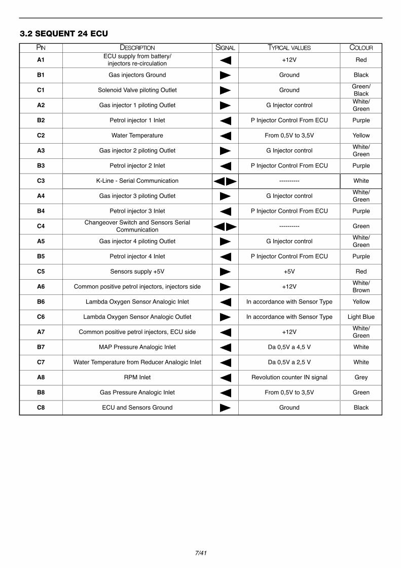
3.2 SEQUENT 24 ECU
DDEESSCCRRIIPPTTIIOONN SSIIGGNNAALLPPIINN TTYYPPIICCAALL VVAALLUUEESS CCOOLLOOUURR
ECU supply from battery/injectors re-circulationA1 +12V Red
Gas injectors GroundB1 Ground Black
Solenoid Valve piloting OutletC1 Ground Green/Black
Gas injector 1 piloting OutletA2 G Injector control White/Green
Petrol injector 1 InletB2 P Injector Control From ECU Purple
Water TemperatureC2 From 0,5V to 3,5V Yellow
Gas injector 2 piloting OutletA3 G Injector control White/Green
Petrol injector 2 InletB3 P Injector Control From ECU Purple
K-Line - Serial CommunicationC3 ---------- White
Gas injector 3 piloting OutletA4 G Injector control White/Green
Petrol injector 3 InletB4 P Injector Control From ECU PurpleChangeover Switch and Sensors Serial
CommunicationC4 ---------- Green
Gas injector 4 piloting OutletA5 G Injector control White/Green
Petrol injector 4 InletB5 P Injector Control From ECU Purple
Sensors supply +5VC5 +5V Red
Common positive petrol injectors, injectors sideA6 +12V White/Brown
Lambda Oxygen Sensor Analogic InletB6 In accordance with Sensor Type Yellow
Lambda Oxygen Sensor Analogic OutletC6 In accordance with Sensor Type Light Blue
Common positive petrol injectors, ECU sideA7 +12V White/Green
MAP Pressure Analogic InletB7 Da 0,5V a 4,5 V White
Water Temperature from Reducer Analogic InletC7 Da 0,5V a 2,5 V White
RPM InletA8 Revolution counter IN signal Grey
Gas Pressure Analogic InletB8 From 0,5V to 3,5V Green
ECU and Sensors GroundC8 Ground Black

8/41
3.3 SEQUENT 56 ECU
1° Connector from Pin 1 to Pin 28DDEESSCCRRIIPPTTIIOONN SSIIGGNNAALLPPIINN TTYYPPIICCAALL VVAALLUUEESS CCOOLLOOUURR
Engine water temperature1 From 0,5V to 3,5V Yellow
Pressure sensor supply+5V2 +5V Red
Pressure sensor Analogical input 3 From 0,5V to 3,5 V Green
Pressure sensor 2 Analogical input - Optional4 ---------- ----------Lambda Oxygen Sensor PRECAT 1 Signal Analogical
input 5 In accordance with Sensor Type YellowLambda Oxygen Sensor PRECAT 2 Signal Analogical
input 6 In accordance with Sensor Type Yellow
---------- ----------7 ---------- ----------
Actuators external relay control8 +12V White/Green
K-line – Serial communication9 ---------- White
---------- ----------10 ---------- ----------
Input from Crankshaft or Revolution counter11 Crankshaft or Revolution counter INsignal Grey
ECU SUPPLY +12V Vehicle battery 12 +12V Red
Signal TTL input from Changeover switch (COM)13 ---------- Green
Gas solenoid valve n°1 control14 Ground Green/Black
Gas Injector 1 Control15 G Injector control White/Green
Gas Injector 2 Control16 G Injector control White/Green
Gas Injector 3 Control17 G Injector control White/Green
Gas Injector 4 Control18 G Injector control White/Green
Gas injectors ground19 Ground Black
Actuators re-circulation20 +12V Green
Gas Injector 5 Control21 G Injector control White/Green
Gas Injector 6 Control22 G Injector control White/Green
Gas Injector 7 Control23 G Injector control White/Green
Gas Injector 8 Control24 G Injector control White/Green
Petrol injector 5 (injectors side)25 P Injector Control to Inj Orange
Petrol injector 6 (injectors side)26 P Injector Control to Inj Orange
Petrol injector 7 (injectors side)27 P Injector Control to Inj Orange
Petrol injector 8 (injectors side)28 P Injector Control to Inj Orange

9/41
2° Connector from Pin 29 to Pin 56DDEESSCCRRIIPPTTIIOONN SSIIGGNNAALLPPIINN TTYYPPIICCAALL VVAALLUUEESS CCOOLLOOUURR
MAP analogical input29 From 0,5V to 4,5 V White
Temperature sensor analogical input30 From 0,5V to 2,5 V White
Inertial switch inlet31 ---------- ----------
Temperature sensor 2 analogical input – PTS Optional32 ---------- ----------
Lambda Oxygen Sensor PRECAT1 Emulation Output 33 In accordance with Sensor Type Light Blue
Lambda Oxygen Sensor PRECAT2 Emulation Output 34 In accordance with Sensor Type Light Blue
---------- ----------35 ---------- ----------
TPS analogical input36 According to TPS sensor0 - 5 V o 0 -12 V
White/Purple
Screening for analogical signals shield / body37 Ground ----------
---------- ----------38 ---------- ----------
Ground from battery39 Ground Black
---------- ----------40 ---------- ----------
Voltage +12V under key41 +12V Brown
Gas solenoid valve 2 control42 Ground Green/Black
Petrol injector n°1 (ECU side)43 P Injector Control From ECU Purple
Petrol injector n°1 (injectors side)44 P Injector Control to Inj Orange
Petrol injector n°2 (ECU side)45 P Injector Control From ECU Purple
Petrol injector n°2 (injectors side)46 P Injector Control to Inj Orange
Gas injectors ground 247 Ground Black
Actuators re-circulation 248 +12V Green
Petrol injector n°3 (ECU side)49 P Injector Control From ECU Purple
Petrol injector n°3 (injectors side)50 P Injector Control to Inj Orange
Petrol injector n°4 (ECU side)51 P Injector Control From ECU Purple
Petrol injector n°4 (injectors side)52 P Injector Control to Inj Orange
Petrol injector n°5 (ECU side)53 P Injector Control From ECU Purple
Petrol injector n°6 (ECU side)54 P Injector Control From ECU Purple
Petrol injector n°7 (ECU side)55 P Injector Control From ECU Purple
Petrol injector n°8 (ECU side)56 P Injector Control From ECU Purple

10/41
3.4 SEQUENT 24 MY07 ECU
DDEESSCCRRIIPPTTIIOONN SSIIGGNNAALLPPIINN TTYYPPIICCAALL VVAALLUUEESS CCOOLLOOUURR
Actuators PositiveA1 +12V Green
Gas Injectors GroundB1 Ground Black
Supply +12V from Battery PositiveC1 +12V Red
Gas Injector 1 Piloting OutletA2 G Injector control White/Green
Petrol Injector 1 InletB2 P Injector Control From ECU Purple
Petrol Injector 1 OutletC2 P Injector Control to Inj Orange
Gas Injector 2 Piloting OutletA3 G Injector control White/Green
Petrol Injector 2 InletB3 P Injector Control From ECU Purple
Petrol Injector 2 OutletC3 P Injector Control to Inj Orange
Gas Injector 3 Piloting OutletA4 G Injector control White/Green
Petrol Injector 3 InletB4 P Injector Control From ECU Purple
Petrol Injector 3 OutletC4 P Injector Control to Inj Orange
Gas Injector 4 Piloting OutletA5 G Injector control White/Green
Petrol Injector 4 OutletB5 P Injector Control From ECU Purple
Petrol Injector 4 OutletC5 P Injector Control to Inj Orange
K-Line – Serial CommunicationA6 ---------- White
Lambda Oxygen Sensor Analogical InletB6 In accordance with Sensor Type Yellow
Sensors Supply +5VC6 +5V Red
Gas Pressure Analogical InletA7 From 0,5 to 4,5 V Green
Map Pressure Analogical InletB7 From 0,5V to 4,5 V White
Water Temperature from Reducer Analogical InletC7 From 0,5V to 2,5 V White
RPM InletA8 Revolution counter IN signal Grey
Voltage +12V Under KeyB8 +12V Brown
Battery GroundC8 Ground Black

11/41
3.5 SEQUENT SDI ECU
1° Connector from Pin 1 to Pin 28DDEESSCCRRIIPPTTIIOONN SSIIGGNNAALLPPIINN TTYYPPIICCAALL VVAALLUUEESS CCOOLLOOUURR
Engine water temperature1 From 0,5V to 3,5V Yellow
Pressure sensor supply +5V2 +5V Red
Pressure sensor analogical input3 From 0,5V to 3,5 V Green
Pressure sensor 2 analogical input -Optional4 ---------- ----------Lambda Oxygen Sensor PRECAT 1 Signal Analogical
input 5 In accordance with Sensor Type YellowLambda Oxygen Sensor PRECAT 2 signal Analogical
input 6 In accordance with Sensor Type YellowLambda Oxygen Sensor POSTCAT
signal Analogical input7 ---------- ----------
Actuators external relay control8 +12V White/Green
K-line – Serial communication9 ---------- White
Can Bus Line10 ----------
Input from Crankshaft or Revolution counter11 Crankshaft or Revolution counter INsignal Grey
ECU Supply +12V Vehicle battery12 +12V Red
Signal TTL input from Changeover switch (COM)13 ---------- Green
Gas solenoid valve n°1 control14 +12V Green
Gas Injector 1 Control15 G Injector control White/Green
Gas Injector 2 Control16 G Injector control White/Green
Gas Injector 3 Control17 G Injector control White/Green
Gas Injector 4 Control18 G Injector control White/Green
Gas injectors ground19 Ground Black
Actuators re-circulation20 +12V Green
Gas Injector 5 control21 G Injector control White/Green
Gas Injector 6 control22 G Injector control White/Green
Petrol injectors 5 positive23 P Injector positive White
Petrol injectors 6 positive24 P Injector positive White
Petrol injector n°2(injectors side)25 P Injector Control to Inj Orange
Petrol injector n°5(injectors side)26 P Injector Control to Inj Orange
Petrol injector n°6(injectors side)27 P Injector Control to Inj Orange
Petrol injector n°3 (injectors side)28 P Injector Control to Inj Orange
12/41
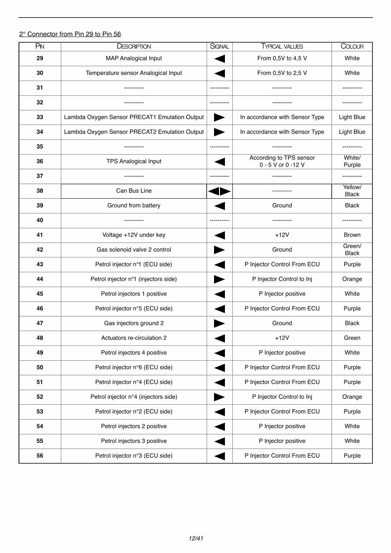
2° Connector from Pin 29 to Pin 56DDEESSCCRRIIPPTTIIOONN SSIIGGNNAALLPPIINN TTYYPPIICCAALL VVAALLUUEESS CCOOLLOOUURR
MAP Analogical Input29 From 0,5V to 4,5 V White
Temperature sensor Analogical Input30 From 0,5V to 2,5 V White
---------- ----------31 ---------- ----------
---------- ----------32 ---------- ----------
Lambda Oxygen Sensor PRECAT1 Emulation Output33 In accordance with Sensor Type Light Blue
Lambda Oxygen Sensor PRECAT2 Emulation Output34 In accordance with Sensor Type Light Blue
---------- ----------35 ---------- ----------
TPS Analogical Input36 According to TPS sensor0 - 5 V or 0 -12 V
White/Purple
---------- ----------37 ---------- ----------
Can Bus Line38 ---------- Yellow/Black
Ground from battery39 Ground Black
---------- ----------40 ---------- ----------
Voltage +12V under key41 +12V Brown
Gas solenoid valve 2 control42 Ground Green/Black
Petrol injector n°1 (ECU side)43 P Injector Control From ECU Purple
Petrol injector n°1 (injectors side)44 P Injector Control to Inj Orange
Petrol injectors 1 positive45 P Injector positive White
Petrol injector n°5 (ECU side)46 P Injector Control From ECU Purple
Gas injectors ground 247 Ground Black
Actuators re-circulation 248 +12V Green
Petrol injectors 4 positive49 P Injector positive White
Petrol injector n°6 (ECU side)50 P Injector Control From ECU Purple
Petrol injector n°4 (ECU side)51 P Injector Control From ECU Purple
Petrol injector n°4 (injectors side)52 P Injector Control to Inj Orange
Petrol injector n°2 (ECU side)53 P Injector Control From ECU Purple
Petrol injectors 2 positive54 P Injector positive White
Petrol injectors 3 positive55 P Injector positive White
Petrol injector n°3 (ECU side)56 P Injector Control From ECU Purple

13/41
3.6 SEQUENT PLUG & DRIVE ECU
1° Connector from Pin 1 to Pin 28DDEESSCCRRIIPPTTIIOONN SSIIGGNNAALLPPIINN TTYYPPIICCAALL VVAALLUUEESS CCOOLLOOUURR
Engine water temperature1 From 0,5V to 3,5V Yellow
Pressure sensor supply +5V2 +5V Red
PTS Pressure sensor analogical input 3 From 0,5V to 3,5 V Green
---------- ----------4 ---------- ----------Lambda Oxygen Sensor PRECAT 1 Signal Analogical
input5 In accordance with Sensor Type YellowLambda Oxygen Sensor PRECAT 2 signal Analogical
input6 In accordance with Sensor Type Yellow
---------- ----------7 ---------- ----------
Actuators external relay control8 +12V White/Green
K-line – Serial communication9 ---------- White
Can BUS – Socket OBD connection10 ---------- Yellow
Input from Crankshaft or Revolution counter11 Crankshaft or Revolution counter INsignal Grey
ECU Supply +12V Vehicle battery12 +12V Red
Socket OBD connection – K-line13 ---------- White
Gas solenoid valve n°1 control14 Ground Green/Black
Gas Injector 1 Control15 G Injector control White/Green
Gas Injector 2 Control16 G Injector control White/Green
Gas Injector 3 Control17 G Injector control White/Green
Gas Injector 4 Control18 G Injector control White/Green
Gas injectors ground19 Ground Black
Actuators re-circulation20 +12V Green
Gas Injector 5 control21 G Injector control White/Green
Gas Injector 6 control22 G Injector control White/Green
Gas Injector 7 control23 G Injector control White/Green
Gas Injector 8 control24 G Injector control White/Green
Petrol injector n°5 (injectors side)25 P Injector Control to Inj Orange
Petrol injector n°6 (injectors side)26 P Injector Control to Inj Orange
Petrol injector n°7 (injectors side)27 P Injector Control to Inj Orange
Petrol injector n°8 (injectors side)28 P Injector Control to Inj Orange
14/41
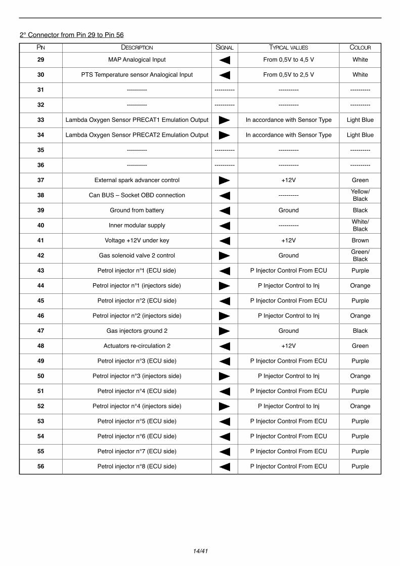
2° Connector from Pin 29 to Pin 56DDEESSCCRRIIPPTTIIOONN SSIIGGNNAALLPPIINN TTYYPPIICCAALL VVAALLUUEESS CCOOLLOOUURR
MAP Analogical Input29 From 0,5V to 4,5 V White
PTS Temperature sensor Analogical Input30 From 0,5V to 2,5 V White
---------- ----------31 ---------- ----------
---------- ----------32 ---------- ----------
Lambda Oxygen Sensor PRECAT1 Emulation Output33 In accordance with Sensor Type Light Blue
Lambda Oxygen Sensor PRECAT2 Emulation Output34 In accordance with Sensor Type Light Blue
---------- ----------35 ---------- ----------
---------- ----------36 ---------- ----------
External spark advancer control37 +12V Green
Can BUS – Socket OBD connection38 ---------- Yellow/Black
Ground from battery39 Ground Black
Inner modular supply40 ---------- White/Black
Voltage +12V under key41 +12V Brown
Gas solenoid valve 2 control42 Ground Green/Black
Petrol injector n°1 (ECU side)43 P Injector Control From ECU Purple
Petrol injector n°1 (injectors side)44 P Injector Control to Inj Orange
Petrol injector n°2 (ECU side)45 P Injector Control From ECU Purple
Petrol injector n°2 (injectors side)46 P Injector Control to Inj Orange
Gas injectors ground 247 Ground Black
Actuators re-circulation 248 +12V Green
Petrol injector n°3 (ECU side)49 P Injector Control From ECU Purple
Petrol injector n°3 (injectors side)50 P Injector Control to Inj Orange
Petrol injector n°4 (ECU side)51 P Injector Control From ECU Purple
Petrol injector n°4 (injectors side)52 P Injector Control to Inj Orange
Petrol injector n°5 (ECU side)53 P Injector Control From ECU Purple
Petrol injector n°6 (ECU side)54 P Injector Control From ECU Purple
Petrol injector n°7 (ECU side)55 P Injector Control From ECU Purple
Petrol injector n°8 (ECU side)56 P Injector Control From ECU Purple

15/41
4. COMPONENTS DIAGNOSTIC
4.1 GAS INJECTOR
Coil resistance check
Signals check
Working check
Entering the Actuators Test section of Sequent program you can check the gas injectors good working.If you run this test on gas injector 1 for instance, you can pilot it, checking in this way its good working. If nothing happens after you send the control, then there is a problem on the injector controlled (gas injector 1, in theexample) and it is necessary to check and eventually to replace the gas injector, the wiring or the gas ECU.
4.2 GAS/PETROL INJECTORS TIMING
For the good working of the system, it’s necessary to have a perfect parallelism between injectors, so that the petrolinjector 1 signal is the one that guides the gas injector1 and so on. A timing not correct involves problems during thechangeover and in all tip-in situations.Correction procedure for injectors wiring errors:
Entering the Diagnostic > Actuators Test section of Sequent program, proceed as following:1. Deselect all the injectors cells. Now, the engine will run completely in petrol mode.2. Select the injector 1 cell. 3. If gas injector 1 inject in the right cylinder (the one corresponding to the petrol injector named 1), engine will run in theright way. In this case, repeat the procedure from step 1 for the next injector. If instead there is a problem, proceed withstep 4.4. Selectioned gas injector must be moved: you have just to move its connector on another gas injector, until the rightworking of the engine.5. Repeat procedure from step 1 with all the others injectors, until find the right position for all the gas injectors connec-tors.You can apply this procedure with the following systems: Sequent standard, Sequent Fast, Sequent FastNess, Sequent56, Sequent Direct Injection, Sequent Plug&Drive.For Sequent 24 MY07 system, it is more difficult to recognize the injectors sequence because of its semi-sequential injec-tors changeover, so that injectors break will take two injectors a time (1 and 4, 2 and 3). For Sequent 24 system you cannot use this diagnostic because the petrol injectors cut has made by the common positivewire of injectors control.
MMEETTHHOODDOOLLOOGGYY IINNSSTTRRUUMMEENNTTVVEERRIIFFIICCAATTIIOONN TTYYPPIICCAALL VVAALLUUEESS WWAAVVEE SSHHAAPPEESS
Check resistancebetween the two injector
clampsTester, Multimeter.Disconnected
Injector Connector 2 Ω ------------
MMEETTHHOODDOOLLOOGGYY IINNSSTTRRUUMMEENNTTVVEERRIIFFIICCAATTIIOONN TTYYPPIICCAALL VVAALLUUEESS WWAAVVEE SSHHAAPPEESS
Check signals fromtheinjector clamps Tester, Oscilloscope.Engine switched on
in LPG mode
Green: 11-14V
White\Green: injector signalas sideways

16/41
4.3 BACK AND FRONT GAS SOLENOID VALVE
Coil resistance check
Signals check
Working check
In order to verify the good working of front and back solenoid valve you can use two strategies.
1° PROCEDURE:
Back SV: after disconnecting the front solenoid valve inlet pipe, by using the Actuators Test section of Sequent programyou can excite the back solenoid valve coil. Now you should hear the back Sv clickand you should also have a gas leaka-ge from the exhaust pipe previously deconnected. If this doesn’t happen, it is necessary to check and eventually to repla-ce the electric coil, the wiring or the Gas ECU.
Warning: After the test connect again the exhaust pipe and check if there are leakages by means ofthe “Effe 91” spray
Front Sv: after disconnecting the front solenoid valve outlet pipe, by using the Actuators Test section of Sequent program,you can excite the front solenoid valve coil and, in this way, open it. Now you should hear the front Sv click and youshould also have a gas leakage from the Sv outlet. If this doesn’t happen, it is necessary to check and eventually toreplace the front solenoid valve, the wiring or the Gas ECU.
Warning: After the test connect again the exhaust pipe and check if there are leakages by means ofthe “Effe 91” spray
MMEETTHHOODDOOLLOOGGYY IINNSSTTRRUUMMEENNTTVVEERRIIFFIICCAATTIIOONN TTYYPPIICCAALL VVAALLUUEESS WWAAVVEE SSHHAAPPEESS
Check resistancebetween the two sole-
noid valve clampsTester, Multimeter.Disconnected coil
connectorFront (red): 9,5-10 ΩBack: 11,8 – 12,2 Ω ------------
MMEETTHHOODDOOLLOOGGYY IINNSSTTRRUUMMEENNTTVVEERRIIFFIICCAATTIIOONN TTYYPPIICCAALL VVAALLUUEESS WWAAVVEE SSHHAAPPEESS
Check signals fromthesolenoid valve injector
clampsTester, Oscilloscope.Engine switched on
in LPG mode
Tester, Green: 11-14V
Green/Black: Groundsupplied by the ECU
------------

17/41
2° PROCEDURE: Close the tap situated on the multivalve gas outlet and after switching the vehicle on and changing over toLPG, consume all the unburnt gas present in the tank. Switch the vehicle off and let the control board turned on. On thehandheld PC, in Diagnostic/Data Visualization section, P1 pressure value will be decreased at about 1000 mbar, that’s tosay at the atmospheric pressure value. This should mean gas absence in the pipes.Now you can open again the multivalve tap.
Through the Actuators Test, by acting first on back solenoid valve control and then on the front one, you should see theP1 pressure increase (that you can display in Diagnostic-Data Display). If this doesn’t happen, it is necessary to checkand eventually to replace the front or back solenoid valve, the wiring or the Gas ECU.
4.4 PRESSURE SENSOR
Signals check
Working check
PTS measures pressure and LPG temperature inside the rail. You can check the right working by means of Sequent pro-gram.
P1 Pressure: in Diagnostic\Data Visualization section you can display P1 Pressure value of the LPG in the rail. Pressurevalue at idle in LPG mode should amount at about 1800-2000 mbar, that’s to say the MAP value (300-450 mbar) +Genius reducer Delta-P (1450-1550 mbar). You can obtain a further control on PTS sensor by reading the pressure valuewith empty Gas loop.Close the tap situated on the multivalve gas outlet and after switching the vehicle on and changing to LPG, consume allthe unburnt gas present in the tank.Switch the vehicle off and let the control board turned on.In Diagnostic/Data Visualization section, P1 pressure value will be decreased at about 1000 mbar, that’s to say at theatmospheric pressure value. If this doesn’t happen, it is necessary to check and eventually to replace the PTS sensor,the wiring or the Gas ECU.
MMEETTHHOODDOOLLOOGGYY IINNSSTTRRUUMMEENNTTVVEERRIIFFIICCAATTIIOONN TTYYPPIICCAALL VVAALLUUEESS WWAAVVEE SSHHAAPPEESS
Check signals fromSensor clamps Tester, Oscilloscope.
Connected sensorconnector+Car swit-
ched on in gasmode
Red: 5 VBlack: Ground
Green: 2 V – 2,5VWhite: 0,6 V – 2,5 V
------------

18/41
4.5 LEVEL SENSOR (LITTLE WINDOW SITUATED ON THE MULTIVALVE)
Little Window Resistance Check
Signals check
Working check
Entering the Setting up\Level Calibration section of Sequent program you can set up at your discretion level indication onthe 4 LEDs.
4.6 ACTUATORS RELAY
Actuators Relay provides supply (Green) at all the system actuators when vehicle change to LPG. White\Green control isa ground and comes directly from the Sequent ECU when you change to LPG.
MMEETTHHOODDOOLLOOGGYY IINNSSTTRRUUMMEENNTTVVEERRIIFFIICCAATTIIOONN TTYYPPIICCAALL VVAALLUUEESS WWAAVVEE SSHHAAPPEESS
Check resistancebetween the two clamps
of wiring coming fromthe tank
Tester, Multimeter.Disconnected LittleWindow Connector
Full tank: 0 Ω
Tank 80%: 90 Ω------------
MMEETTHHOODDOOLLOOGGYY IINNSSTTRRUUMMEENNTTVVEERRIIFFIICCAATTIIOONN TTYYPPIICCAALL VVAALLUUEESS WWAAVVEE SSHHAAPPEESS
Check signals on wiringcoming from the tank Tester, Oscilloscope.
Connected LittleWindow
Connect.+Car tur-ned on in gas mode
Tester, Full tank: 45 mV
Tank 80%: 990 mV------------
GreenRELAY
N.C.Green
Red
Red
30 30
86
86
87
87
858587a 87a
N.C.
Red Red
White/Green
White/Green

19/41
Check signals at rest (Petrol mode)
Check signals in LPG mode
Working check
Entering the Actuators Test section of Sequent program you can checkthe actuators relay good working. Running thistest you can pilot the actuators relay in an intermittent way and check its good working.If nothing happens after you send the control, then there is a problem on the actuators relay control and it is necessary tocheck and eventually to replace the actuators relay, the wiring or the gas ECU.
MMEETTHHOODDOOLLOOGGYY IINNSSTTRRUUMMEENNTTVVEERRIIFFIICCAATTIIOONN TTYYPPIICCAALL VVAALLUUEESS WWAAVVEE SSHHAAPPEESS
Check signals on Relayterminals Tester, Oscilloscope.Vehicle in petrol
modeRed (86-30): 11-14V
green: no signalWhite\Green: 12 V
------------
MMEETTHHOODDOOLLOOGGYY IINNSSTTRRUUMMEENNTTVVEERRIIFFIICCAATTIIOONN TTYYPPIICCAALL VVAALLUUEESS WWAAVVEE SSHHAAPPEESS
Check signals on Relayterminals Tester, Oscilloscope.Vehicle in LPG
mode
Red (86-30): 11-14VGreen: 11-14V
White\Green: Groundsupplied from the ECU
------------

20/41
5. PROBLEMS AND SOLUTIONS
PROBLEMS SOLUTIONS
1 Vehicle doesn’t change over
2 Vehicle stalls while changing over to gas
3 Vehicle doesn’t start up or works wrongly in petrol
4 Changeover switch doesn’t switch on
5 A/More level LED/LEDs doesn’t/don’t work
6 Vehicle works wrongly at idle
• Changeover switch is in Petrol forced mode (Red LED tur-ned on)
• This changeover conditions are not valid:- Engine water temperature- Time since the starting
• Verify pressures• Verify Gas Solenoid valve working
• Verify the 15A fuse• Verify connections on the actuators relay• Replace the relay• Verify gas injectors working• Verify Gas ECU
• Verify injectors cut wiring• Verify Gas ECU
• Verify changeover switch wiring continuity• Replace the 5A fuse• Replace the changeover switch• Verify the ECU working
• Verify changeover switch wiring or replace indicator LEDs• In these cases, the cause could also be the ECU, therefo-
re verify that it communicates with PC interface and even-tually try to replace it
• One or more injectors don’t work correctly; check itsworking with Actuators Test
• Verify wirings of Gas injectors controls• Verify pressures and signals by means of Sequent pro-
gram

21/41
7 Computer doesn’t communicate
8 Changeover swtich doesn’t display GAS level
9 There’s smell of gas
10 Vehicle starts up wrongly in petrol mode
11 Vehicle changes over in petrol mode during tip-in(Enabled Buzzer)
12 Fuse 5A burns out
13 Vehicle changes over in petrol mode (Disabled Buzzer)
• Turn the vehicle control board on• Check the 5A - 15A fuse• Replace the communication wire• Replace Gas ECU• Check Communication section on PC
• LEDs don’t work• Verify ECU• Verify level wiring
• Check leakages with spray “Effe 91”
• Verify possible gas leakages inside the manifold: with theComputer verify P1 pressure value before starting up thevehicle. If it was 1000 mbar (Atmosferic Pressure) youcould have a gas leakage inside the manifold.
• Verify gas injectors good working• Verify Gas reducer: check possible gas leakage thanks to
the feedback inside the manifold
• Verify with the Computer Delta-P and P1 Pressure trend• Verify gas quantity and pressure inside the tank• Verify possibles narrowings in gas pipes• Verify System filter choking
• Verify fuses position5A on red wires sect. 1.515A on red wires sect. 2.5
• Verify short-circuits
• Verify RPM signal• Verify Gas Temperature signal• Verify continuity of RPM taking signal grey wire.• Verify temperature sensor working• Replace Temperature sensor• Replace gas ECU• Verify system supplies

22/41
6. ERRORS CODESSEQUENT DIAGNOSTIC

Dia
gnost
ic g
uid
e
1. DT
C P1
105 M
AP(M
anifo
ld A
bsol
ute P
ress
ure)
Sen
sor
It is
poss
ible
to d
iagno
se th
e fol
lowi
ng fa
ilure
s:Si
gnal
valu
e und
er m
inim
um th
resh
old
Not r
easo
nabl
e sig
nal
Sign
al va
lue o
ver m
axim
um th
resh
old
Poss
ible
caus
es:
1-M
APsig
nal w
ire is
in s
hort-
circu
it wi
th n
egat
ivesu
pply;
2-M
APsig
nal w
ire is
not
conn
ecte
d;3-
MAP
sens
or is
fault
y;4-
Sequ
ent E
CU is
fault
y.
Repa
iring
pro
cedu
re:
1-Ch
eck M
APse
nsor
conn
ecto
r; 2-
Verif
y th
e ab
senc
e of
sho
rt-cir
cuit
betw
een
MAP
signa
l wire
and
neg
ative
supp
ly;3-
Chec
k M
APsig
nal w
ire c
ontin
uity
from
sen
sor
conn
ecto
r (or
takin
g po
int s
ignal)
up
to g
as E
CUco
nnec
tor;
4-Re
place
MAp
sens
or;
5-Re
place
Seq
uent
ECU
.
Oper
atio
n ch
eck:
1-Er
ase
the
erro
r;2-
Star
t the
eng
ine, c
hang
e ov
er to
gas
mod
e an
dve
rify c
redib
ility o
f rea
d va
lues;
3-Ch
eck e
rrors
mem
ory.
Poss
ible
caus
es:
1-M
APsig
nal w
ire is
in sh
ort-c
ircuit
with
pos
itive
sup-
ply;
2-M
APse
nsor
is fa
ulty;
3-Se
quen
t ECU
is fa
ulty.
Repa
iring
pro
cedu
re:
1-Ch
eck M
APse
nsor
conn
ecto
r; 2-
Verif
y th
e ab
senc
e of
sho
rt-cir
cuit
betw
een
MAP
signa
l wire
and
pos
itive
supp
ly;3-
Repla
ce M
Ap se
nsor
;4-
Repla
ce S
eque
nt E
CU.
Oper
atio
n ch
eck:
1-Er
ase
the
erro
r;2-
Star
t the
eng
ine, c
hang
e ov
er to
gas
mod
e an
dve
rify c
redib
ility o
f rea
d va
lues;
3-Ch
eck e
rrors
mem
ory.
Poss
ible
caus
es:
1-Se
nsor
settin
g is
not c
orre
ct;2-
The
sens
or in
stalle
d is
diffe
rent
from
the
one
set
up b
y the
softw
are;
3-M
APse
nsor
is fa
ulty;
4-Se
quen
t ECU
is fa
ulty;
5-Er
ror d
ue to
ano
ther
dev
ice fa
ilure
(see
Rep
airing
proc
edur
e).
Repa
iring
pro
cedu
re:
1-Ve
rify M
APse
nsor
settin
g;2-
If yo
u ha
ve a
not
-reas
onab
le er
ror o
n P1
pre
ssur
ese
nsor
too,
follo
w sa
me
indi
catio
ns s
uita
ble
for
erro
r P11
90;
3-If
you
have
an
erro
r on
TPS
too,
follo
w sa
me
indi-
catio
ns su
itable
for e
rror P
1120
;4-
If yo
u ha
ve a
n er
ror o
n se
nsor
s sup
ply te
nsion
, fol-
low th
e sa
me
indica
tions
suita
ble fo
r erro
r P16
08;
5-Re
place
MAp
sens
or;
6-Re
place
Seq
uent
ECU
.
Oper
atio
n ch
eck:
1-Er
ase
the
erro
r;2-
Star
t the
eng
ine, c
hang
e ov
er to
gas
mod
e an
dve
rify c
redib
ility o
f rea
d va
lues;
3-Ch
eck e
rrors
mem
ory.
23/41
24/41
Dia
gnost
ic g
uid
e
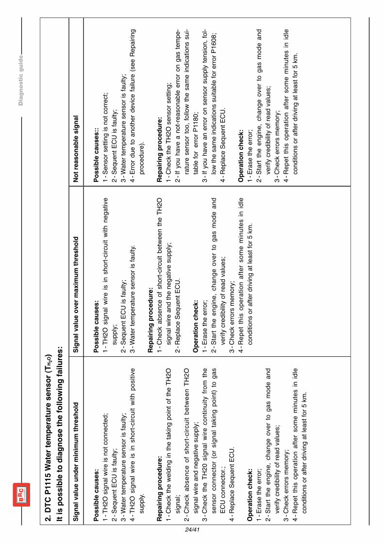
2. DT
C P1
115 W
ater
tem
pera
ture
sens
or (T
H 2O)
It is
poss
ible
to d
iagno
se th
e fol
lowi
ng fa
ilure
s:Si
gnal
valu
e und
er m
inim
um th
resh
old
Not r
easo
nabl
e sig
nal
Sign
al va
lue o
ver m
axim
um th
resh
old
Poss
ible
caus
es:
1-TH
2O si
gnal
wire
is n
ot co
nnec
ted;
2-Se
quen
t ECU
is fa
ulty;
3-W
ater
tem
pera
ture
sens
or is
fault
y;4-
TH2O
sign
al wi
re is
in s
hort-
circu
it wi
th p
ositiv
esu
pply.
Repa
iring
pro
cedu
re:
1-Ch
eck
the
weldi
ng in
the
takin
g po
int o
f the
TH2
Osig
nal;
2-Ch
eck
abse
nce
of s
hort-
circu
it be
twee
n TH
2Osig
nal w
ire a
nd n
egat
ive su
pply;
3-Ch
eck
the
TH20
sign
al wi
re c
ontin
uity
from
the
sens
or c
onne
ctor (
or s
ignal
takin
g po
int) t
o ga
sEC
U co
nnec
tor.;
4-Re
place
Seq
uent
ECU
.
Oper
atio
n ch
eck:
1-Er
ase
the
erro
r;2-
Star
t the
eng
ine, c
hang
e ov
er to
gas
mod
e an
dve
rify c
redib
ility o
f rea
d va
lues;
3-Ch
eck e
rrors
mem
ory;
4-Re
pet t
his o
pera
tion
afte
r som
e m
inute
s in
idle
cond
itions
or a
fter d
riving
at le
ast f
or 5
km.
Poss
ible
caus
es:
1-TH
2O s
ignal
wire
is in
sho
rt-cir
cuit
with
neg
ative
supp
ly;2-
Sequ
ent E
CU is
fault
y;3-
Wat
er te
mpe
ratu
re se
nsor
is fa
ulty.
Repa
iring
pro
cedu
re:
1-Ch
eck
abse
nce
of s
hort-
circu
it be
twee
n th
e TH
2Osig
nal w
ire a
nd th
e ne
gativ
e su
pply;
2-Re
place
Seq
uent
ECU
.
Oper
atio
n ch
eck:
1-Er
ase
the
erro
r;2-
Star
t the
eng
ine, c
hang
e ov
er to
gas
mod
e an
dve
rify c
redib
ility o
f rea
d va
lues;
3-Ch
eck e
rrors
mem
ory;
4-Re
pet t
his
oper
atio
n af
ter s
ome
min
utes
in id
leco
nditio
ns o
r afte
r driv
ing a
t leas
t for
5 km
.
Poss
ible
caus
es::
1-Se
nsor
settin
g is
not c
orre
ct;2-
Sequ
ent E
CU is
fault
y;3-
Wat
er te
mpe
ratu
re se
nsor
is fa
ulty;
4-Er
ror d
ue to
ano
ther
dev
ice fa
ilure
(see
Rep
airing
proc
edur
e).
Repa
iring
pro
cedu
re:
1-Ch
eck t
he T
H2O
sens
or se
tting;
2-If
you
have
a n
ot-re
ason
able
erro
r on
gas
tem
pe-
ratu
re s
enso
r too
, foll
ow th
e sa
me
indica
tions
sui-
table
for
erro
r P11
80;
3-If
you
have
an
erro
r on
sens
or s
upply
tens
ion, f
ol-low
the
sam
e ind
icatio
ns su
itable
for e
rror P
1608
;4-
Repla
ce S
eque
nt E
CU.
Oper
atio
n ch
eck:
1-Er
ase
the
erro
r;2-
Star
t the
eng
ine, c
hang
e ov
er to
gas
mod
e an
dve
rify c
redib
ility o
f rea
d va
lues;
3-Ch
eck e
rrors
mem
ory;
4-Re
pet t
his o
pera
tion
afte
r som
e m
inute
s in
idle
cond
itions
or a
fter d
riving
at le
ast f
or 5
km.

25/41
Dia
gnost
ic g
uid
e
3. DT
C P1
120 T
PS T
hrot
tle P
oten
tiom
eter
(Thr
ottle
Pos
ition
Sen
sor)
It is
poss
ible
to d
iagno
se th
e fol
lowi
ng fa
ilure
s:Si
gnal
valu
e und
er m
inim
um th
resh
old
Not r
easo
nabl
e sig
nal
Sign
al va
lue o
ver m
axim
um th
resh
old
Poss
ible
caus
es:
1-TP
S sig
nal w
ire is
in s
hort-
circu
it wi
th n
egat
ivesu
pply;
2-PS
sign
al wi
re is
not
conn
ecte
d;3-
Sequ
ent E
CU is
fault
y;4-
TPS
pote
ntiom
eter
is fa
ulty.
Repa
iring
pro
cedu
re:
1-Ch
eck t
he ri
ght c
onne
ction
of t
he T
PS si
gnal
wire
;2-
Chec
k th
e ab
senc
e of
sho
rt-cir
cuit
betw
een
TPS
signa
l wire
and
neg
ative
supp
ly;3-
Chec
k the
TPS
sign
al wi
re co
ntinu
ity fr
om th
e se
n-so
r con
necto
r (or
sign
al ta
king
point
) to
the
gas
ECU
conn
ecto
r;4-
Repla
ce S
eque
nt E
CU.
Oper
atio
n ch
eck:
1-Er
ase
the
erro
r;2-
Star
t the
eng
ine, c
hang
e ov
er to
gas
mod
e an
dve
rify c
redib
ility o
f rea
d va
lues;
3-Ch
eck e
rrors
mem
ory.
Poss
ible
caus
es:
1-TP
S sig
nal w
ire is
in s
hort-
circu
it wi
th p
ositiv
e su
p-ply
;2-
Sequ
ent E
CU is
fault
y;3-
TPS
pote
ntiom
eter
is fa
ulty.
Repa
iring
pro
cedu
re:
1-Ch
eck
the
abse
nce
of s
hort-
circu
it be
twee
n TP
Ssig
nal w
ire a
nd p
ositiv
e su
pply;
2-Re
place
Seq
uent
ECU
.
Oper
atio
n ch
eck:
1-Er
ase
the
erro
r;2-
Star
t the
eng
ine, c
hang
e ov
er to
gas
mod
e an
dve
rify c
redib
ility o
f rea
d va
lues;
3-Ch
eck e
rrors
mem
ory.
Poss
ible
caus
es:
1-Se
nsor
settin
g is
not c
orre
ct;2-
Erro
r due
to a
noth
er d
evice
failu
re (s
ee R
epair
ingpr
oced
ure)
;3-
Sequ
ent E
CU is
fault
y.
Repa
iring
pro
cedu
re:
1-Ch
eck t
he T
PS se
nsor
settin
g;2-
If yo
u ha
ve a
n er
ror o
n se
nsor
sup
ply te
nsion
, fol-
low th
e sa
me
indica
tions
suita
ble fo
r erro
r P16
08;
3-Re
place
Seq
uent
ECU
.
Oper
atio
n ch
eck:
1-Er
ase
the
erro
r;2-
Star
t the
eng
ine, c
hang
e ov
er to
gas
mod
e an
dve
rify c
redib
ility o
f rea
d va
lues;
3-Ch
eck e
rrors
mem
ory.

26/41
Dia
gnost
ic g
uid
e
4. DT
C P1
130 e
P11
50 P
RECA
T 1 L
ambd
a Oxig
en S
enso
r (sig
nal)
and
PREC
AT2 L
ambd
a Oxig
en S
enso
r (sig
nal)
It is
poss
ible
to d
iagno
se th
e fol
lowi
ng fa
ilure
s:No
t rea
sona
ble s
igna
lSi
gnal
valu
e ove
r max
imum
thre
shol
d
Poss
ible
caus
es:
1-PR
ECAT
1 (o
r PRE
CAT
2) si
gnal
wire
is in
shor
t-circ
uit w
ith p
ositiv
e su
pply;
2-Se
quen
t ECU
is fa
ulty;
3-PR
ECAT
1 (o
r PRE
CAT
2) la
mbd
a ox
igen
sens
or is
fault
y.
Repa
iring
pro
cedu
re:
1-Ch
eck t
hat L
ambd
a ox
igen
sens
or si
gnal
had
been
corre
ctly t
aken
;2-
Chec
k th
e ab
senc
e of
sho
rt-cir
cuit
betw
een
PREC
AT1
(or P
RECA
T2)
sign
alwi
re a
nd p
ositiv
e su
pply;
3-
Repla
ce S
eque
nt E
CU;
4-Re
place
PRE
CAT
1 (o
r PRE
CAT
2) la
mbd
a ox
igen
sens
or.
Oper
atio
n ch
eck:
1-Er
ase
the
erro
r;2-
Star
t the
eng
ine a
nd ch
ange
ove
r fro
m p
etro
l to g
as m
ode;
3-Ve
rify t
he cr
edibi
lity o
f rea
d va
lues;
4-Dr
iving
in g
as m
ode
at le
ast f
or 1
0 km
with
med
ium lo
ad;
5-Ch
eck e
rrors
mem
ory.
Poss
ible
caus
es:
1-PR
ECAT
1 (o
r PRE
CAT
2) si
gnal
wire
is n
ot co
nnec
ted;
2-Se
nsor
settin
g is
not c
orre
ct;3-
Sequ
ent E
CU is
fault
y;4-
PREC
AT1
(or P
RECA
T2)
lam
bda
oxige
n se
nsor
is fa
ulty.
Repa
iring
pro
cedu
re:
1-Ch
eck t
hat L
ambd
a ox
igen
sens
or si
gnal
had
been
corre
ctly t
aken
;2-
Chec
k th
e PR
ECAT
1 (o
r PRE
CAT
2) s
ignal
wire
con
tinuit
y fro
m th
e se
nsor
(or
signa
l takin
g po
int) t
o th
e ga
s ECU
conn
ecto
r;3-
Chec
k th
e ab
senc
e of
sho
rt-cir
cuit
betw
een
PREC
AT1
(or P
RECA
T2)
sign
alwi
re a
nd n
egat
ive su
pply;
4-Ch
eck t
he s
enso
r set
ting;
5-Re
place
Seq
uent
ECU
;6-
Repla
ce P
RECA
T1
(or P
RECA
T2)
lam
bda
oxige
n se
nsor
.
Oper
atio
n ch
eck:
1-Er
ase
the
erro
r;2-
Star
t the
eng
ine a
nd ch
ange
ove
r fro
m p
etro
l to g
as m
ode;
3-Ve
rify t
he cr
edibi
lity o
f rea
d va
lues;
4-Dr
iving
in g
as m
ode
at le
ast f
or 1
0 km
with
med
ium lo
ad;
5-Ch
eck e
rrors
mem
ory.
27/41
Dia
gnost
ic g
uid
e
5. DT
C P1
131 e
P11
51 P
RECA
T 1 L
ambd
a Oxig
en S
enso
r (gr
ound
) and
PRE
CAT
2 Lam
bda O
xigen
Sen
sor (
grou
nd)
It is
poss
ible
to d
iagno
se th
e fol
lowi
ng fa
ilure
s:No
t rea
sona
ble s
igna
l
Poss
ible
caus
es:
1-PR
ECAT
1 (o
r PRE
CAT
2) si
gnal
wire
is in
shor
t-circ
uit w
ith su
pply
wire
s;2-
PREC
AT1
(or P
RECA
T2)
sign
al wi
re is
not
conn
ecte
d;3-
Sens
or se
tting
is no
t cor
rect;
4-PR
ECAT
1 (o
r PRE
CAT
2) la
mbd
a ox
igen
sens
or is
fault
y.
Repa
iring
pro
cedu
re:
1-Ch
eck t
hat P
RECA
T1 (o
r PRE
CAT
2) g
roun
d ha
d be
en co
rrectl
y tak
en;
2-Ch
eck t
he a
bsen
ce o
f sho
rt-cir
cuit b
etwe
en th
e PR
ECAT
1 (o
r PRE
CAT
2) g
roun
d wi
re a
nd th
e su
pply
wire
s.3-
Chec
k the
PRE
CAT
1 (o
r PRE
CAT
2) g
roun
d wi
re co
ntinu
ity fr
om th
e se
nsor
(or s
ignal
takin
g po
int) t
o th
e ga
s ECU
conn
ecto
r;4-
Chec
k the
sen
sor s
ettin
g;5-
Repla
ce P
RECA
T1
(or P
RECA
T2)
lam
bda
oxige
n se
nsor
.
Oper
atio
n ch
eck:
1-Er
ase
the
erro
r;2-
Star
t the
eng
ine a
nd ch
ange
ove
r fro
m p
etro
l to g
as m
ode;
3-Ve
rify t
he cr
edibi
lity o
f rea
d va
lues;
4-Dr
iving
in g
as m
ode
at le
ast f
or 1
0 km
with
med
ium lo
ad;
5-Ch
eck e
rrors
mem
ory.

28/41
Dia
gnost
ic g
uid
e
6. DT
C P1
180 G
as te
mpe
ratu
re se
nsor
(TGA
S)It
is po
ssib
le to
diag
nose
the f
ollo
wing
failu
res:
Sign
al va
lue u
nder
min
imum
thre
shol
dNo
t rea
sona
ble s
igna
lSi
gnal
valu
e ove
r max
imum
thre
shol
d
Poss
ible
caus
es:
1-TG
AS si
gnal
wire
is n
ot co
nnec
ted;
2-TG
AS se
nsor
is fa
ulty;
3-Se
quen
t ECU
is fa
ulty;
4-TG
AS s
ignal
wire
is in
sho
rt-cir
cuit
with
pos
itive
supp
ly.
Repa
iring
pro
cedu
re:
1-Ch
eck t
he T
GAS
conn
ecto
r;2-
Chec
k th
e ab
senc
e of
sho
rt-cir
cuit
betw
een
TGAS
signa
l wire
and
pos
itive
supp
ly;3-
Chec
k TG
AS s
ignal
wire
con
tinuit
y fro
m th
e se
n-so
r (or
sign
al ta
king
point
) to
the
gas E
CU co
nnec
-to
r;4-
Repla
ce T
GAS
sens
or;
5-Re
place
Seq
uent
ECU
.
Oper
atio
n ch
eck:
1-Er
ase
the
erro
r;2-
Star
t the
eng
ine, c
hang
e ov
er to
gas
mod
e an
dve
rify c
redib
ility o
f rea
d va
lues;
3-Ch
eck e
rrors
mem
ory;
4-Re
pet t
his o
pera
tion
afte
r som
e m
inute
s in
idle
cond
itions
(abo
ut 1
0/15
min
) or a
fter d
rivin
g at
least
for 5
km.
Poss
ible
caus
es:
1-TG
AS s
ignal
wire
is in
sho
rt-cir
cuit
with
neg
ative
supp
ly;2-
TGAS
sens
oris
fault
y;3-
Sequ
ent E
CU is
fault
y.
Repa
iring
pro
cedu
re:
1-Ch
eck t
he T
GAS
conn
ecto
r;2-
Chec
k th
e ab
senc
e of
sho
rt-cir
cuit
betw
een
TGAS
signa
l wire
and
neg
ative
supp
ly;3-
Repla
ce T
GAS
sens
or;
4-Re
place
Seq
uent
ECU
.
Oper
atio
n ch
eck:
1-Er
ase
the
erro
r;2-
Star
t the
eng
ine, c
hang
e ov
er to
gas
mod
e an
dve
rify c
redib
ility o
f rea
d va
lues;
3-Ch
eck e
rrors
mem
ory;
4-Re
pet t
his
oper
atio
n af
ter s
ome
min
utes
in id
leco
nditi
ons
(abo
ut 1
0/15
min
) or a
fter d
rivin
g at
least
for 5
km.
Poss
ible
caus
es:
1-Se
nsor
settin
g is
not c
orre
ct;2-
Erro
r due
to a
noth
er d
evice
failu
re (s
ee R
epair
ingpr
oced
ure)
;3-
TGAS
sens
oris
fault
y;4-
Sequ
ent E
CU is
fault
y.
Repa
iring
pro
cedu
re:
1-Ch
eck T
GAS
sens
or se
tting;
2-Ch
eck t
he in
stalle
d se
nsor
be
the
suita
ble o
ne;
3-If
you
have
a n
ot-re
ason
able
erro
r on
TGAS
sen
-so
r too
, foll
ow th
e sa
me
indica
tions
suit
able
for
erro
r P11
15;
4-If
you
have
an
erro
r on
the
sens
ors s
upply
tens
ion,
follo
w th
e sa
me
indi
catio
ns s
uita
ble
for e
rror
P160
8;5-
Repla
ce T
GAS
sens
or;
6 - R
eplac
e Se
quen
t ECU
.
Oper
atio
n ch
eck:
1-Er
ase
the
erro
r;2-
Star
t the
eng
ine, c
hang
e ov
er to
gas
mod
e an
dve
rify c
redib
ility o
f rea
d va
lues;
3-Ch
eck e
rrors
mem
ory;
4-Re
pet t
his o
pera
tion
afte
r som
e m
inute
s in
idle
cond
itions
(abo
ut 1
0/15
min
) or a
fter d
rivin
g at
least
for 5
km.

29/41
Dia
gnost
ic g
uid
e
7. DT
C P1
190 (
1191
) P1 P
ress
ure S
enso
rIt
is po
ssib
le to
diag
nose
the f
ollo
wing
failu
res:
Sign
al va
lue u
nder
min
imum
thre
shol
dNo
t rea
sona
ble s
igna
lSi
gnal
valu
e ove
r max
imum
thre
shol
d
Poss
ible
caus
es:
1-P1
sign
al wi
re is
in s
hort-
circu
it wi
th n
egat
ive s
up-
ply;
2-P1
sign
al wi
re is
not
conn
eced
;3-
P1 p
ress
ure
sens
or is
fault
y;4-
Sequ
ent E
CU is
fault
y.
Repa
iring
pro
cedu
re:
1-Ch
eck P
1 se
nsor
conn
ecto
r;2-
Chec
k th
e ab
senc
e of
sho
rt-cir
cuit
betw
een
P1sig
nal w
ire a
nd n
egat
ive su
pply;
3-Ch
eck P
1 sig
nal w
ire co
ntinu
ity fr
om th
e se
nsor
toth
e ga
s ECU
conn
ecto
r;4-
Repla
ce P
1 se
nsor
;5-
Repla
ce S
eque
nt E
CU.
Oper
atio
n ch
eck:
1-Er
ase
the
erro
r;2-
Star
t the
eng
ine, c
hang
e ov
er to
gas
mod
e an
dve
rify c
redib
ility o
f rea
d va
lues;
3-Ch
eck e
rrors
mem
ory.
Poss
ible
caus
es:
1-P1
sign
al wi
re is
in s
hort-
circu
it wi
th p
ositiv
e su
p-ply
;2-
P1 p
ress
ure
sens
or is
fault
y;3-
Sequ
ent E
CU is
fault
y.
Repa
iring
pro
cedu
re:
1-Ch
eck P
1 se
nsor
conn
ecto
r;2-
Chec
k th
e ab
senc
e of
sho
rt-cir
cuit
betw
een
P1sig
nal w
ire a
nd p
ositiv
e su
pply;
3-Re
place
P1
sens
or;
4-Re
place
Seq
uent
ECU
.
Oper
atio
n ch
eck:
1-Er
ase
the
erro
r;2-
Star
t the
eng
ine, c
hang
e ov
er to
gas
mod
e an
dve
rify c
redib
ility o
f rea
d va
lues;
3-Ch
eck e
rrors
mem
ory.
Poss
ible
caus
es:
1-Se
nsor
settin
g is
not c
orre
ct;2-
Erro
r due
to a
noth
er d
evice
failu
re (s
ee R
epair
ingpr
oced
ure)
;3-
P1 p
ress
ure
sens
or is
fault
y;4-
Sequ
ent E
CU is
fault
y.
Repa
iring
pro
cedu
re:
1-Ch
eck P
1 se
nsor
settin
g;2-
Chec
k the
insta
lled
sens
or b
e th
e su
itable
one
;3-
If yo
u ha
ve a
not
-reas
onab
le er
ror o
n M
APpr
essu
-re
sen
sor t
oo, f
ollow
the
sam
e ind
icatio
ns s
uitab
lefo
r P11
05 e
rror;
4-If
you
have
an
erro
r on
the
TPS
sens
or to
o, fo
llow
the
sam
e ind
icatio
ns su
itable
for P
1120
erro
r;5-
If yo
u ha
ve a
n er
ror o
n th
e se
nsor
s sup
ply te
nsion
too,
follo
w th
e sa
me
indica
tions
suita
ble fo
r P16
08er
ror;
6-Re
place
P1
sens
or (a
nd/o
r P1b
is);
7-Re
place
Seq
uent
ECU
.
Oper
atio
n ch
eck:
1-Er
ase
the
erro
r;2-
Star
t the
eng
ine, c
hang
e ov
er to
gas
mod
e an
dve
rify c
redib
ility o
f rea
d va
lues;
3-Ch
eck e
rrors
mem
ory.

30/41
Dia
gnost
ic g
uid
e
8. DT
C P1
201 P
1202
P12
03 P
1204
P12
05 P
1206
P12
07 P
1208
GAS
cylin
der i
njec
tor c
ontro
ls fro
m 1
to 8
It is
poss
ible
to d
iagno
se th
e fol
lowi
ng fa
ilure
s:Si
gnal
valu
e ove
r max
imum
thre
shol
dSi
gnal
valu
e und
er m
inim
um th
resh
old
Poss
ible
caus
es:
1-In
jecto
rs w
iring
is in
shor
t-circ
uit w
ith n
egat
ive su
pply;
2-In
jecto
rs w
iring
is no
t con
necte
d;3-
Sequ
ent E
CU is
fault
y;4-
Injec
tors
are
fault
y.
Repa
iring
pro
cedu
re:
1-Ch
eck i
njecto
rs co
nnec
tors
;2-
Chec
k the
abs
ence
of s
hort-
circu
it bet
ween
injec
tors
wirin
g an
d ne
gativ
e su
pply;
3-Ch
eck i
njecto
rs w
iring
cont
inuity
from
the
injec
tor c
onne
ctor t
o th
e ga
s ECU
con-
necto
r;4-
Chec
k inje
ctors
impe
danc
e (b
etwe
en 1
and
2 O
hm);
5-Re
place
Seq
uent
ECU
;6-
Repla
ce in
jecto
rs.
Oper
atio
n ch
eck:
1-Er
ase
the
erro
rs;
2-Ta
ke e
ngine
at s
tead
y con
dition
unt
il the
pet
rol/g
as ch
ange
over
tem
pera
ture
;3-
Drive
in g
as m
ode
with
diffe
rent
s loa
d co
nditio
ns a
nd w
ith R
PM <
400
0 rp
m;
4-Ch
eck e
rrors
mem
ory.
Poss
ible
caus
es:
1-In
jecto
rs w
iring
is in
shor
t-circ
uit w
ith p
ositiv
e su
pply;
2-Se
quen
t ECU
is fa
ulty;
3-In
jecto
rs a
re fa
ulty.
Repa
iring
pro
cedu
re:
1-Ch
eck i
njecto
rs co
nnec
tors
;2-
Chec
k the
abs
ence
of s
hort-
circu
it bet
ween
injec
tors
wirin
g an
d po
sitive
supp
ly;3-
Chec
k inje
ctors
impe
danc
e (b
etwe
en 1
and
2 O
hm).;
4-Re
place
Seq
uent
ECU
;5-
Repla
ce in
jecto
rs.
Oper
atio
n ch
eck:
1-Er
ase
the
erro
rs;
2-Ta
ke e
ngine
at s
tead
y con
dition
unt
il the
pet
rol/g
as ch
ange
over
tem
pera
ture
;3-
Drive
in g
as m
ode
with
diffe
rent
s loa
d co
nditio
ns a
nd w
ith R
PM <
400
0 rp
m;
4-Ch
eck e
rrors
mem
ory.

31/41
Dia
gnost
ic g
uid
e
9. DT
C P1
230 A
ctua
tors
relay
cont
rol
It is
poss
ible
to d
iagno
se th
e fol
lowi
ng fa
ilure
s:Si
gnal
valu
e und
er m
inim
um th
resh
old
Not r
easo
nabl
e sig
nal
Sign
al va
lue o
ver m
axim
um th
resh
old
Poss
ible
caus
es:
1-Ac
tuat
ors r
elay w
iring
is in
shor
t-circ
uit w
ith n
egat
i-ve
supp
ly;2-
Actu
ator
s rela
y wirin
g is
not c
onne
cted;
3-Re
lay is
fault
y;4-
Sequ
ent E
CU is
fault
y.
Repa
iring
pro
cedu
re:
1-Ch
eck a
ctuat
ors r
elay w
iring;
2-Ch
eck t
he a
bsen
ce o
f sho
rt-cir
cuit b
etwe
en a
ctua-
tors
relay
wirin
g an
d ne
gativ
e su
pply;
3-Ch
eck
actu
ator
s re
lay
wirin
g co
ntin
uity
from
its
conn
ecto
r to
the
gas E
CU o
ne;
4-Re
place
actu
ator
s rela
y;5-
Repla
ce S
eque
nt E
CU.
Oper
atio
n ch
eck:
1-Er
ase
the
erro
rs;
2-St
art t
he e
ngine
and
chan
ge o
ver t
o ga
s mod
e;3-
Chec
k erro
rs m
emor
y.
Poss
ible
caus
es:
1-Ac
tuat
ors
relay
wirin
g is
in sh
ort-c
ircuit
with
pos
iti-ve
supp
ly;2-
Relay
is fa
ulty;
3-Se
quen
t ECU
is fa
ulty.
Repa
iring
pro
cedu
re:
1-Ch
eck a
ctuat
ors r
elay w
iring;
2-Ch
eck
the
abse
nce
of s
hort-
circu
it be
twee
n ac
tua-
tors
relay
wirin
g an
d po
sitive
supp
ly;3-
Repla
ce a
ctuat
ors r
elay;
4-Re
place
Seq
uent
ECU
.
Oper
atio
n ch
eck:
1-Er
ase
the
erro
rs;
2-St
art t
he e
ngine
and
chan
ge o
ver t
o ga
s mod
e;3-
Chec
k erro
rs m
emor
y.
Poss
ible
caus
es:
1-Ac
tuat
ors r
elay w
iring
is in
shor
t-circ
uit w
ith n
egat
i-ve
supp
ly;2-
Actu
ator
s rela
y wirin
g is
not c
onne
cted;
3-Re
lay is
fault
y;4-
Sequ
ent E
CU is
fault
y.
Repa
iring
pro
cedu
re:
1-Ch
eck a
ctuat
ors r
elay w
iring;
2-Ch
eck t
he a
bsen
ce o
f sho
rt-cir
cuit b
etwe
en a
ctua-
tors
rela
y wi
ring
and
posi
tive
supp
ly o
r GND
(gro
und)
;3-
Chec
k inje
ctors
and
solen
oid va
lves c
onne
ctors
;4-
Repla
ce a
ctuat
ors r
elay;
5-Re
place
Seq
uent
ECU
.
Oper
atio
n ch
eck:
1-Er
ase
the
erro
rs;
2-St
art t
he e
ngine
and
chan
ge o
ver t
o ga
s mod
e;3-
Chec
k erro
rs m
emor
y.

32/41
Dia
gnost
ic g
uid
e
10. D
TC P
1231
P12
32 P
1233
P12
34 G
AS S
olen
oid
valve
s [1..
4]It
is po
ssib
le to
diag
nose
the f
ollo
wing
failu
res:
Sign
al va
lue u
nder
min
imum
thre
shol
dSi
gnal
valu
e ove
r max
imum
thre
shol
d
Poss
ible
caus
es:
1-GA
S so
lenoid
valve
s wirin
g is
in sh
ort-c
ircuit
with
neg
ative
supp
ly;2-
GAS
solen
oid va
lves w
iring
is no
t con
necte
d;3-
Solen
oid va
lves a
re fa
ulty;
4-Se
quen
t ECU
is fa
ulty.
Repa
iring
pro
cedu
re:
1-Ch
eck G
AS so
lenoid
valve
s wirin
g;2-
Chec
k th
e ab
senc
e of
sho
rt-cir
cuit
betw
een
GAS
solen
oid v
alves
wirin
g an
dne
gativ
e su
pply;
3-Ch
eck
GAS
solen
oid v
alves
wirin
g co
ntinu
ity fr
om th
eir c
onne
ctor t
o th
e ga
sEC
U on
e;4-
Repla
ce G
AS so
lenoid
valve
s wirin
g;5-
Repla
ce G
AS so
lenoid
valve
;6-
Repla
ce S
eque
nt E
CU.
Oper
atio
n ch
eck:
1-Er
ase
the
erro
rs;
2-St
art t
he e
ngine
and
chan
ge o
ver t
o ga
s mod
e;3-
Chec
k erro
rs m
emor
y.
Poss
ible
caus
es:
1-GA
S so
lenoid
valve
s wirin
g is
in sh
ort-c
ircuit
with
pos
itive
supp
ly;2-
Solen
oid va
lves a
re fa
ulty;
3-Se
quen
t ECU
is fa
ulty.
Repa
iring
pro
cedu
re:
1-Ch
eck G
AS so
lenoid
valve
s wirin
g;2-
Chec
k th
e ab
senc
e of
sho
rt-cir
cuit
betw
een
GAS
solen
oid v
alves
wirin
g an
dpo
sitive
supp
ly;3-
Chec
k GA
S so
lenoid
valv
es w
iring
cont
inuity
from
their
con
necto
r to
the
gas
ECU
one;
4-Re
place
GAS
solen
oid va
lves w
iring;
5-Re
place
Seq
uent
ECU
.
Oper
atio
n ch
eck:
1-Er
ase
the
erro
rs;
2-St
art t
he e
ngine
and
chan
ge o
ver t
o ga
s mod
e;3-
Chec
k erro
rs m
emor
y.

33/41
Dia
gnost
ic g
uid
e
11. D
TC P
1335
RPM
or c
ranc
ksha
ft sig
nal
It is
poss
ible
to d
iagno
se th
e fol
lowi
ng fa
ilure
s:Si
gnal
not p
rese
ntNo
t rea
sona
ble s
igna
lSi
gnal
valu
e ove
r max
imum
thre
shol
d
Poss
ible
caus
es:
1-RP
M o
r cra
nksh
aft s
ignal
wire
is in
terru
pted
;2-
Sequ
ent E
CU is
fault
y;3-
Shor
t circ
uit to
ward
s pos
itive
or n
egat
ive;
4-RP
M o
r cra
nksh
aft s
ignal
wirin
g is
in sh
ort-c
ircuit
with
the
supp
lies.
Repa
iring
pro
cedu
re:
1-Ch
eck t
hat s
ignal
takin
g po
int is
corre
ct;2-
Chec
k RP
M o
r cra
nksh
aft s
ignal
wirin
g co
ntinu
ityfro
m th
e co
nnec
tor (
or ta
king
poin
t) to
the
gas
ECU
conn
ecto
r;3-
Repla
ce S
eque
nt E
CU.
Oper
atio
n ch
eck:
1-Er
ase
the
erro
rs;
2-St
art t
he e
ngine
, cha
nge
over
to g
as m
ode
and
verif
y cre
dibilit
y of r
ead
value
s;3-
Chec
k erro
rs m
emor
y.
Poss
ible
caus
es:
1-Se
nsor
settin
g is
not c
orre
ct;2-
Sequ
ent E
CU is
fault
y.
Repa
iring
pro
cedu
re:
1-Ch
eck
settin
g pa
ram
eter
s an
d co
rrect
conn
ectio
nfo
r the
RPM
sign
al;2-
Chec
k RPM
wire
/wire
s con
tinuit
y fro
m th
e sig
nal o
rta
king
point
to th
e ga
s ECU
conn
ecto
r;3-
Repla
ce S
eque
nt E
CU.
Oper
atio
n ch
eck:
1-Er
ase
the
erro
rs;
2-St
art t
he e
ngine
, cha
nge
over
to g
as m
ode
and
verif
y cre
dibilit
y of r
ead
value
s;3-
Chec
k erro
rs m
emor
y.
Poss
ible
caus
es:
1-Se
nsor
settin
g is
not c
orre
ct;2-
RPM
or c
rank
shaf
t sign
al wi
ring
is in
shor
t-circ
uitwi
th t
he su
pplie
s;3-
Sequ
ent E
CU is
fault
y.
Repa
iring
pro
cedu
re:
1-Ch
eck t
hat s
ignal
takin
g po
int is
corre
ct;2-
Chec
k the
RPM
or c
rank
shaf
t sign
al se
tting;
3-Ch
eck
the
abse
nce
of s
hort-
circu
it be
twee
n RP
Mor
cran
cksh
aft s
ignal
wirin
g an
d th
e su
pplie
s;4-
Repla
ce S
eque
nt E
CU.
Oper
atio
n ch
eck:
1-Er
ase
the
erro
rs;
2-St
art t
he e
ngine
, cha
nge
over
to g
as m
ode
and
verif
y cre
dibilit
y of r
ead
value
s;3-
Chec
k erro
rs m
emor
y.
34/41
Dia
gnost
ic g
uid
e
12. D
TC P
1420
POS
TCAT
lam
bda o
xigen
sens
or (s
igna
l)It
is po
ssib
le to
diag
nose
the f
ollo
wing
failu
res:
Sign
al va
lue o
ver m
axim
um th
resh
old
Not r
easo
nabl
e sig
nal
Poss
ible
caus
es:
1-PO
STCA
Tsig
nal w
ire is
in sh
ort w
ith p
ositiv
e su
pply;
2-Se
quen
t ECU
is fa
ulty;
3-PO
STCA
Tse
nsor
is fa
ulty.
Repa
iring
pro
cedu
re:
1-Ch
eck l
ambd
a ox
ygen
sens
or si
gnal
had
been
corre
ctly t
aken
;2-
Chec
k th
e ab
senc
e of
sho
rt-cir
cuit
betw
een
POST
CAT
signa
l wire
and
pos
itive
supp
ly;3-
Repla
ce S
eque
nt E
CU;
4-Re
place
POS
TCAT
sens
or.
Oper
atio
n ch
eck:
1-Er
ase
the
erro
r;2-
Star
t the
eng
ine a
nd ch
ange
ove
r fro
m p
etro
l to g
as m
ode;
3-Ve
rify t
he cr
edibi
lity o
f rea
d va
lues;
4-Dr
iving
in g
as m
ode
at le
ast f
or 1
0 km
with
med
ium lo
ad;
5-Ch
eck e
rrors
mem
ory.
Poss
ible
caus
es:
1-PO
STCA
Tsig
nal w
ire is
not
conn
ecte
d;2-
Sens
or se
tting
is no
t cor
rect;
3-Se
quen
t ECU
is fa
ulty;
4-PO
STCA
Tse
nsor
is fa
ulty.
Repa
iring
pro
cedu
re:
1-Ch
eck l
ambd
a ox
ygen
sens
or si
gnal
had
been
corre
ctly t
aken
;2-
Chec
k POS
TCAT
signa
l wire
cont
inuity
from
its co
nnec
tor (
or si
gnal
takin
g po
int)
to g
as E
CU co
llecto
r;3-
Chec
k sen
sor s
ettin
g;4-
Repla
ce S
eque
nt E
CU;
5-Re
place
POS
TCAT
sens
or.
Oper
atio
n ch
eck:
1-Er
ase
the
erro
r;2-
Star
t the
eng
ine a
nd ch
ange
ove
r fro
m p
etro
l to g
as m
ode;
3-Ve
rify t
he cr
edibi
lity o
f rea
d va
lues;
4-Dr
iving
in g
as m
ode
at le
ast f
or 1
0 km
with
med
ium lo
ad;
5-Ch
eck e
rrors
mem
ory.
35/41
Dia
gnost
ic g
uid
e
13. D
TC P
1460
Gas
leve
l sen
sor
It is
poss
ible
to d
iagno
se th
e fol
lowi
ng fa
ilure
s:Si
gnal
valu
e ove
r max
imum
thre
shol
dSi
gnal
valu
e und
er m
inim
um th
resh
old
Poss
ible
caus
es:
1-Le
vel s
enso
r wirin
g is
inter
rupt
ed;
2-Le
vel s
enso
r wirin
g is
in sh
ort-c
ircuit
with
pos
itive
supp
ly;3-
Sens
or se
tting
is no
t cor
rect;
4-Le
vel s
enso
r is f
aulty
;5-
Erro
r due
to a
noth
er d
evice
failu
re (s
ee R
epair
ing p
roce
dure
);6-
Sequ
ent E
CU is
fault
y.
Repa
iring
pro
cedu
re:
1-Ch
eck l
evel
sens
or co
nnec
tor;
2-Ch
eck t
he a
bsen
ce o
f sho
rt-cir
cuit b
etwe
en le
vel s
enso
r wirin
g an
d po
sitive
bat
-te
ry;
3-Ch
eck l
evel
sens
or w
iring
cont
inuity
up
to th
e ga
s ECU
conn
ecto
r;4-
Chec
k lev
el se
nsor
settin
g;5-
Chec
k BRC
sens
or in
stalle
d be
the
suita
ble o
ne;
6-If
you
have
an
erro
r on
the
sens
or s
upply
tens
ion, f
ollow
the
sam
e ind
icatio
nssu
itable
for e
rror P
1608
;7-
Repla
ce le
vel s
enso
r.8-
Repla
ce S
eque
nt E
CU.
Oper
atio
n ch
eck:
1-Er
ase
the
erro
rs;
2-St
art t
he e
ngine
, cha
nge
over
to g
as m
ode
and
verif
y cre
dibilit
y of r
ead
value
s;3-
Chec
k erro
rs m
emor
y.
Poss
ible
caus
es:
1-Le
vel s
enso
r wirin
g is
in sh
ort-c
ircuit
with
the
grou
nd;
2-Se
nsor
settin
g is
not c
orre
ct;3-
Leve
l sen
sor i
s fau
lty;
4-Er
ror d
ue to
ano
ther
dev
ice fa
ilure
(see
Rep
airing
pro
cedu
re);
5-Se
quen
t ECU
is fa
ulty.
Repa
iring
pro
cedu
re:
1-Ch
eck l
evel
sens
or co
nnec
tor;
2-Ch
eck t
he a
bsen
ce o
f sho
rt-cir
cuit b
etwe
en le
vel s
enso
r wirin
g an
d gr
ound
;3-
Chec
k lev
el se
nsor
wirin
g co
ntinu
ity u
p to
the
gas E
CU co
nnec
tor;
4-Ch
eck l
evel
sens
or se
tting;
5-Ch
eck B
RC se
nsor
insta
lled
be th
e su
itable
one
;6-
If yo
u ha
ve a
n er
ror o
n th
e se
nsor
sup
ply te
nsion
, foll
ow th
e sa
me
indica
tions
suita
ble fo
r erro
r P16
08;
7-Re
place
leve
l sen
sor.
8-Re
place
Seq
uent
ECU
.
Oper
atio
n ch
eck:
1-Er
ase
the
erro
rs;
2-St
art t
he e
ngine
, cha
nge
over
to g
as m
ode
and
verif
y cre
dibilit
y of r
ead
value
s;3-
Chec
k erro
rs m
emor
y.

36/41
Dia
gnost
ic g
uid
e
14. D
TC P
1560
Bat
tery
volta
geIt
is po
ssib
le to
diag
nose
the f
ollo
wing
failu
res:
Sign
al va
lue o
ver m
axim
um th
resh
old
Sign
al va
lue u
nder
min
imum
thre
shol
d
Poss
ible
caus
es:
1-Ba
ttery
volta
ge is
too
high
(> 1
6V);
2-Ba
ttery
volta
ge h
as b
een
take
n in
a wr
ong
point
;3-
Grou
nd re
fere
nce
has b
een
take
n in
a wr
ong
point
;4-
Sequ
ent E
CU is
fault
y.
Repa
iring
pro
cedu
re:
1-Ch
eck b
atte
ry su
pply
wirin
g;2-
Chec
k su
pply
wirin
g co
ntinu
ity (p
ositiv
e ba
ttery
and
gro
und)
from
the
takin
gpo
int to
the
gas E
CU co
nnec
tor;
3-Ch
eck b
atte
ry vo
ltage
with
a vo
ltmet
er;
4-Re
place
Seq
uent
ECU
.
Oper
atio
n ch
eck:
1-Er
ase
the
erro
rs;
2-St
art t
he e
ngine
, cha
nge
over
to g
as m
ode
and
verif
y cre
dibilit
y of r
ead
value
s;3-
Chec
k erro
rs m
emor
y.
Poss
ible
caus
es:
1-Ba
ttery
volta
ge is
too
low (<
6V)
;2-
Batte
ry vo
ltage
has
bee
n ta
ken
in a
wron
g po
int;
3-Gr
ound
refe
renc
e ha
s bee
n ta
ken
in a
wron
g po
int;
4-Se
quen
t ECU
is fa
ulty.
Repa
iring
pro
cedu
re:
1-Ch
eck b
atte
ry su
pply
wirin
g;2-
Chec
k su
pply
wirin
g co
ntinu
ity (p
ositiv
e ba
ttery
and
gro
und)
from
the
takin
gpo
int to
the
gas E
CU co
nnec
tor;
3-Ch
eck b
atte
ry vo
ltage
with
a vo
ltmet
er;;
4-Re
place
Seq
uent
ECU
.
Oper
atio
n ch
eck:
1-Er
ase
the
erro
rs;
2-St
art t
he e
ngine
, cha
nge
over
to g
as m
ode
and
verif
y cre
dibilit
y of r
ead
value
s;3-
Chec
k erro
rs m
emor
y.

37/41
Dia
gnost
ic g
uid
e
15. D
TC P
1608
Sen
sors
supp
ly te
nsio
nIt
is po
ssib
le to
diag
nose
the f
ollo
wing
failu
res:
Sign
al va
lue o
ver m
axim
um th
resh
old
Sign
al va
lue u
nder
min
imum
thre
shol
d
Poss
ible
caus
es:
1-Se
nsor
s sup
ply te
nsion
is to
o hig
h (>
6V)
;2-
Sens
ors
supp
ly wi
ring
is in
shor
t-circ
uit w
ith p
ositiv
e ba
ttery
(it i
nvolv
es a
n er
ror
reco
rding
on
ever
y sen
sor);
3-Se
quen
t ECU
is fa
ulty (
it inv
olves
an
erro
r rec
ordin
g on
eve
ry se
nsor
).
Repa
iring
pro
cedu
re:
1-Ch
eck s
enso
rs su
pply
tens
ion w
iring;
2-Ch
eck s
enso
rs su
pply
tens
ion w
iring
from
gas
ECU
to th
e dif
fere
nt se
nsor
s con
-ne
ctors
;3-
Chec
k gas
ECU
fuse
s con
tinuit
y;4-
Chec
k sen
sors
supp
ly te
nsion
com
ing o
ut fr
om th
e ga
s ECU
with
a vo
ltmet
er;
5-Re
place
Seq
uent
ECU
.
Oper
atio
n ch
eck:
1-Er
ase
the
erro
rs;
2-St
art t
he e
ngine
, cha
nge
over
to g
as m
ode
and
verif
y cre
dibilit
y of r
ead
value
s;3-
Chec
k erro
rs m
emor
y.
Poss
ible
caus
es:
1-Se
nsor
s sup
ply te
nsion
is to
o low
(< 4
V);
2-Se
nsor
s su
pply
wirin
g is
in sh
ort-c
ircuit
with
gro
und
(it in
volve
s an
erro
r rec
or-
ding
on e
very
sens
or);
3-Se
quen
t ECU
is fa
ulty (
it inv
olves
an
erro
r rec
ordin
g on
eve
ry se
nsor
).
Repa
iring
pro
cedu
re:
1-Ch
eck s
enso
rs su
pply
tens
ion w
iring;
2-Ch
eck s
enso
rs su
pply
tens
ion w
iring
from
gas
ECU
to th
e dif
fere
nt se
nsor
s con
-ne
ctors
;3-
Chec
k gas
ECU
fuse
s con
tinuit
y;4-
Chec
k sen
sors
supp
ly te
nsion
com
ing o
ut fr
om th
e ga
s ECU
with
a vo
ltmet
er;
5-Re
place
Seq
uent
ECU
.
Oper
atio
n ch
eck:
1-Er
ase
the
erro
rs;
2-St
art t
he e
ngine
, cha
nge
over
to g
as m
ode
and
verif
y cre
dibilit
y of r
ead
value
s;3-
Chec
k erro
rs m
emor
y.

38/41
Dia
gnost
ic g
uid
e
16. D
TC P
1650
Gas
/pet
rol c
hang
eove
r swi
tch
signa
lIt
is po
ssib
le to
diag
nose
the f
ollo
wing
failu
res:
Sign
al va
lue o
ver m
axim
um th
resh
old
Not r
easo
nabl
e sig
nal
Poss
ible
caus
es:
1-Ch
ange
over
switc
h sig
nal w
ire is
in sh
ort-c
ircuit
with
neg
ative
supp
ly;2-
Chan
geov
er sw
itch
signa
l wire
is n
ot co
nnec
ted;
3-Ga
s/Pet
rol c
hang
eove
r swi
tch is
fault
y;4-
Sequ
ent E
CU is
fault
y;5-
Erro
r due
to a
noth
er d
evice
failu
re (s
ee R
epair
ing p
roce
dure
).
Repa
iring
pro
cedu
re:
1-Ch
eck g
as/p
etro
l cha
ngeo
ver s
witch
conn
ecto
r.2-
Chec
k the
abs
ence
of s
hort-
circu
its b
etwe
en ch
ange
over
switc
h wi
re a
nd su
pply
wire
s;3-
Chec
k ch
ange
over
swi
tch w
ire c
ontin
uity
from
its
conn
ecto
r up
to th
e ga
s EC
Uco
nnec
tor;
4-If
you
have
an
erro
r on
the
sens
or s
upply
tens
ion, f
ollow
the
sam
e ind
icatio
nssu
itable
for e
rror P
1608
;5-
Repla
ce g
as/p
etro
l cha
ngeo
ver s
witch
.6-
Repla
ce S
eque
nt E
CU.
Oper
atio
n ch
eck:
1-Er
ase
the
erro
r;2-
Star
t the
eng
ine a
nd ch
ange
ove
r to
gas m
ode;
3-Ch
eck e
rrors
mem
ory.
Poss
ible
caus
es:
1-Ch
ange
over
switc
h sig
nal w
ire is
in sh
ort-c
ircuit
with
supp
ly;2-
Chan
geov
er sw
itch
signa
l wire
is n
ot co
nnec
ted;
3-Ga
s/Pet
rol c
hang
eove
r swi
tch is
fault
y;4-
Sequ
ent E
CU is
fault
y;5-
Erro
r due
to a
noth
er d
evice
failu
re (s
ee R
epair
ing p
roce
dure
).
Repa
iring
pro
cedu
re:
1-Ch
eck
the
abse
nce
of s
hort-
circu
it be
twee
n ch
ange
over
swi
tch w
iring
and
sup-
ply;
2-Ch
eck c
hang
eove
r swi
tch w
iring
cont
inuity
;3-
Chec
k cha
ngeo
ver s
witch
wirin
g co
nnec
tor;
4-Re
place
chan
geov
er sw
itch.
Oper
atio
n ch
eck:
1-Er
ase
the
erro
r;2-
Star
t the
eng
ine a
nd ch
ange
ove
r to
gas m
ode;
3-Ch
eck e
rrors
mem
ory.

DIAGNOSTIC GUIDE
39/41
7. NOMENCLATURE
Absolute pressure: Pressure measured with reference (value=0) to the perfect vacuum.Battery positive: The pole with higher electric potential of the vehicle battery. Normally it has a voltagebetween 8 and 16V compared to the ground (see “Ground”).Bottom Feed: See “Top Feed”. Particular type of injector, in which path fuel only involves the injector bottompart.CAN Bus: Communication system between ECUs and devices installed on a vehicle.Cartography: See “Mapping”Catalyst: Device installed on the exhaust duct in order to reduce the polluting emissions.Changeover switch: It is the device situated in the passenger compartment which allows to choose the fueltype (gas or petrol).Changeover to Petrol at idle: Strategy which allows the vehicle re-changeover from Gas to Petrol under apredefined RPM threshold. Petrol stay is not definitive but it has two outlet threshold, one on the time and oneon the RPM, that you can both set up from interface.Changeover to Petrol in Cut-Off: Strategy that allows to make petrol injections every time it go out from theCut-Off condition, both for return to idle and for a tip-in. From the program you can set up the RPM thresholduseful to have a valid changeover condition, and the numbers of petrol injections made by the system beforethe automatic re-changeover to gas.Close-Loop: Engine working condition where petrol ECU modifies the carburation according to the signalread by the Lambda oxigen sensor. In this condition ECU searches for the stoichiometry and, because of a notcorrect gas mapping, it should modify the self-mapping parameters and therefore turns the CHECK indicatoron.Cold strategy: Strategy which allows the gas calibration correction when the vehicle is still cold. You canmodify from interface both the Flow correction and the temperature spread in which you can correct the cali-bration.Connector: Device which connects wirings parts with other wiring parts or with electric devices.Crankshaft (sensor): Sensor installed near a gearwheel supportive with the drive shaft; it produces an elec-tric signal that represents the drive shaft position.Cut-Off: Particular engine working condition where injectors don’t supply fuel to the cylinder, so that theyintake pure air. Normally, you are in cut-off during a tip-out, with possible vehicle deceleration (engine brake),starting from rpm not too low.Delta-P: Value calculated from the difference between the P1 (pressure inside gas rail) and the MAP (pressu-re inside the manifold). This parameter allows to recognize the failed supply condition. If Delta-P value decrea-ses under the Delta-P Minimum set up in Changeover, vehicle re-changes over to petrol for end of gas.Diagnostic: Identification process of cause or nature of a problem, a failure, or of a particular condition /situa-tion to find and indicate as wrong working.Duty Cycle: In a rectangular wave-shape is the proportion between the high level duration and the wave-shape period. In formulas, if Ton is the high level duration and Toff is the low level duration, then Tp = Ton +Toff is the period and DC = Ton / Tp = Ton / (Ton+Toff) is the Duty Cycle.ECU: It is the Electronic Control Unit of the engine or of the gas carburation.EOBD: See “OBD”. European On Board Diagnostics. European implementation of OBD systems, regulatedfrom institutions as ISO.Flow: Physical measure that defines the fluid quantity passing through a specific section in a time unit. Massflow defines, for instance, how many grams of a fluid pass through a specific section in a second.Fuel Injectors: See “Rail” It is the element on which injectors are installed; thanks to this element, the gas atthe required pressure can be opportunely supplied at every injector inlet.

DIAGNOSTIC GUIDE
40/41
Gas Injection Strategy in Cut-Off: Only for Sequent24. Strategy which allows the gas injectors advance ope-ning while vehicle is still in Cut-Off condition. You can set up RPM threshold and Gas Injection Time from inter-face. Ex. 3 ms under the 2000 rpm.Ground: Reference electric potential (relative tension amounting to zero Volt). It is also the mass of wires andelectric conductor connected to this potential. Ground potential is on the negative pole (that’s to say at thelower electric potential) of the vehicle battery, so that it’s called battery ground too.Injector: Device which supplies accurate measured quantities of fuel in pressure, injecting them in the intakemanifold.K line: Communication line of engine ECU towards the external diagnostic instrument, according to ISO 9141e ISO 14230 regulations.Lambda Oxigen Sensor: Sensor measuring the oxigen concentration in the exhaust gas. Thanks to this sen-sor the ECU determines if air/fuel mix is too rich or too poor in fuel, permitting the system closed loopworking.LED: Light Emitting Diode. Semiconductor electronic device that can glow if crossed by electric current.LPG: Liquefied Petroleum Gas. It is a fuel coming from petroleum distillation, essentially made up of Butaneand Propane in variable proportions. You can find it in gaseous state at ambient temperature and pressure,whereas it is liquid inside the tank.Magnetic loop: Magnetic flow path, usually made of iron or other iron-magnetic material. It is part of an elec-tromagnetic device (solenoid valve, injector, electric engine, and so on).Mapping/Map: It is the mass of data that defines fuel quantity to dose in accordance with the engine workingconditions.MAP: (Manifold Absolute Pressure) Absolute pressure of the engine intake manifold (see Absolute pressure).It indicates the relative sensor too.Multivalve: Device situated on the tank that performs different functions, controlling the tank filling, the fuellevel, the security protection,and so on.OBD (On Board Diagnostics): See also “Diagnostic”. Monitoring system of all or some inlet and ECU signalcontrol. If it finds one or more signals over the predefined threshold, it informs and records thesystem/systems bad working.Open-Loop: Engine working condition where petrol ECU doesn’t consider anymore the signal read byLambda oxigen sensor. You normally have this condition when you ask to the engine a complete power. ECUenriches carburation in full load searching for the better performance and in order to decrease temperatureinside the catalyst.OR: (O-Ring) Gasket made up of a rubber ring.PC: Personal ComputerPeak & Hold (piloting): See also “Piloting”. Particular injectors piloting that supplies to the coil early a biggercurrent in the opening phase, so that it can reduces the injector opening time (peak); then current goes downto a value enough to maintain the injector open (hold).Piloting: It shows action and way with which electric actuators are controlled by the ECU or other electricdevice, through power electric signals.Positive under key: Tension or electric knot situated before the switch activated by the vehicle ignition key.Normally it has a low potential; it reaches the battery positive potential when you turn the key off.POSTCAT Lambda Oxigen Sensor: Lambda Oxigen Sensor situated after the catalyst.PRECAT Lambda Oxigen Sensor: Lambda Oxigen Sensor situated before the catalyst.Pressure differential: Pressure difference between two zones, for instance between the intake manifold andthe atmospheric pressure.Relative pressure: Pressure measured with reference (value=0) to the atmospheric pressure.Relay: Electromechanic device that can open or close one or more electric contact after appropriate electricpiloting.RPM: Acronym for revolutions per minute. It usually indicates drive shaft rotation speed.RPM Decrease Strategy: Strategy which allows to modify the mapping in condition of return to idle. You canset up Flow correction and strategy work time from interface.

DIAGNOSTIC GUIDE
41/41
Sensor: Device measuring a physical quantity value as temperature, pressure, speed, and it converts it inelectric signal useful to the ECU or to another electric device.Sequential injection: Injection management system of a modern vehicle with fuel electronic injection; herethe injection phase of every cylinder starts and ends according to indipendent times for everyone of them. Theengine ECU verifies these times and correlates them with the cylinder phase and position.Solenoid valve: Electromechanic device that stops a fluid flow. In our case, this device stops gas flow whenit’s not supplied, otherwise it lets the gas flow.Three-way catalyst: Catalyst that reduces the HC, CO and NOx values.Throttle Valve: Valve that regulates the air flow intook from the engine. Normally is controlled from the accele-rator pedal but nowadays it is controlled directly from the petrol ECU more and more.TonG: Gas Injection Time. It shows how long the gas injector stays open in order to supply the required gasflow..TonMinGas: Parameter situated in Map Refinement/Other. It shows the TonP at idle in gas mode. The systemconsiders this value in order to recognize its work mode during the map control: at idle (TonP = TonMinGas) orrunning (TonP > TonMinGas). Value is calculated automatically during the self-mapping, but you can correct itafter checking the mapping at idle.TonP: Petrol Injection Time. It shows how long the petrol injector stays open in order to supply the right cali-bration.Top Feed: See “Bottom Feed”. Particular type of injector, in which path fuel passes through the whole lenghtof the injector in an axial way, arriving from the top and being injected in the low part of the device.TPS: Throttle Valve Position Sensor. It supplies an electric signal that shows the throttle valve opening (see“Throttle Valve”).Wiring: It is the mass of wires going from the ECU connector to all the other system wiring points.