ta133 and ta150 oscilloscope probe user’s guide · ta133 500 mhz oscilloscope probe user's...
TRANSCRIPT
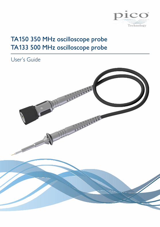
TA150 350 MHz Oscilloscope Probe
DO217-1
USER’S GUIDE
TA150 350 MHz oscilloscope probeTA133 500 MHz oscilloscope probe
User's Guide
2 DO251-1
TA133 and TA150 User's Guide
ManufacturerPMK Mess- und Kommunikationstechnik GmbHKönigsteiner Str. 98D-65812 Bad Soden am TaunusGermany
Sales and supportPico TechnologyJames HouseColmworth Business ParkSt. Neots PE19 8YPUnited Kingdom
EC declaration of conformityPico Technology declares that the following products comply with the requirements of the specified Directives and Standards as listed below. Technical documentation required to demonstrate compliance to the standards is available for inspection by the relevant enforcement authorities. Products carry the CE mark.
Products covered by this declaration:TA133 500 MHz oscilloscope probeTA150 350 MHz oscilloscope probe
EU Directives covered by this declaration:2006/95/EC Low Voltage Equipment Directive2012/19/EU Waste Electrical and Electronic Equipment2011/65/EU Restriction of use of certain Hazardous Substances
The basis on which conformity is being declared:EN61010-1:2010 Safety requirements for electrical equipment for measurement,
control and laboratory use, general equipment requirements.EN61010-031:2002 Safety requirements for hand-held probe assemblies for electrical+ A1:2008 measurement and test.RoHS and WEEE Manufacturer’s analysis of the raw materials used in the
manufacture of the above products.
Your help and efforts are required to protect and keep our environment clean. Therefore either return this product at the end of life to the manufacturer or ensure WEEE compliant collection and treatment yourself. Do not dispose of as unsorted municipal waste.
WarrantyPico Technology warrants this oscilloscope accessory for normal use and operation within specifications for a period of two years from date of shipment and will repair or replace any defective product which was not damaged by negligence, misuse, improper installation, accident or unauthorized repair or modification by the buyer. This warranty is applicable only to defects due to material or workmanship. Pico Technology disclaims any other implied warranties of merchantability or fitness for a particular purpose. Pico Technology will not be liable for any indirect, special, incidental, or consequential damages (including damages for loss of profits, loss of business, loss of use or data, interruption of business and the like), even if Pico Technology has been advised of the possibility of such damages arising from any defect or error in this manual or product.
Information in this publication supersedes that in all previously published material.
Pico Technology is a registered trade mark of Pico Technology Ltd.
Copyright © 2012–2015 Pico Technology Ltd. All rights reserved.
3DO251-1
TA133 and TA150 User's Guide
1. SafetyTo prevent possible electrical shock, fire, personal injury, or damage to the product, carefully read this safety information before attempting to install or use the product. In addition, follow all generally accepted safety practices and procedures for working with and near electricity.The product has been designed and tested in accordance with the European standard publication EN 61010-1:2010, and left the factory in a safe condition.The following safety descriptions are found throughout this guide:A WARNING identifies conditions or practices that could result in injury or death.A CAUTION identifies conditions or practices that could result in damage to the product or equipment to which it is connected.
SymbolsThese safety and electrical symbols may appear on the product or in this guide:
Symbol DescriptionDirect current
Earth (ground) terminalTerminal can be used to make a measurement ground connection. The terminal is NOT a Safety or protective Earth.
Possibility of electric shock
CautionAppearance on the product indicates a need to read these safety and operation instructions.
Do not dispose of this product as unsorted municipal waste.
WARNINGTo prevent injury or death only qualified personnel should use this product, only as instructed and with only accessories supplied or recommended. Protection provided by the product may be impaired if used in a manner not specified by the manufacturer.
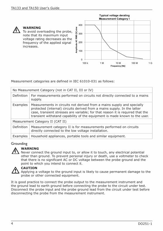
Maximum input rangesThe table and frequency derating plot below indicate the full-scale measurement range and overvoltage protection range for these probes. The full-scale measurement ranges are the maximum voltages that can be accurately measured by the probe. The overvoltage protection ranges are the maximum voltages that will not damage the probe.
WARNINGTo prevent electric shock, do not connect the probe to voltages exceeding the levels below and do take all necessary safety precautions when working on equipment where hazardous live voltages may be present.
Model Full-scale measurement range Overvoltage protection(voltage that will not damage)
TA133 & TA150400 V RMS (not in CAT II) 1250 V transient (not in CAT II)
300 V RMS (CAT II)
4 DO251-1
TA133 and TA150 User's Guide
Typical voltage deratingMeasurement Category I
0
100
200
300
400
100 k 1 M 10 M 100 M 1 GFrequency [Hz]
Am
plitu
de A
C R
MS
[V] s
ineWARNING
To avoid overloading the probe, note that its maximum input voltage rating decreases as the frequency of the applied signal increases.
Measurement categories are defined in IEC 61010-031 as follows:
No Measurement Category (not in CAT II, III or IV)
Definition For measurements performed on circuits not directly connected to a mains supply.
Examples Measurements in circuits not derived from a mains supply and specially protected (internal) circuits derived from a mains supply. In the latter case, transient stresses are variable; for that reason it is required that the transient withstand capability of the equipment is made known to the user.
Measurement Category II (CAT II)
Definition Measurement category II is for measurements performed on circuits directly connected to the low voltage installation.
Examples Household appliances, portable tools and similar equipment.
GroundingWARNINGNever connect the ground input to, or allow it to touch, any electrical potential other than ground. To prevent personal injury or death, use a voltmeter to check that there is no significant AC or DC voltage between the probe ground and the point to which you intend to connect it.CAUTIONApplying a voltage to the ground input is likely to cause permanent damage to the probe or other connected equipment.
It is good practice to connect the probe output to the measurement instrument and the ground lead to earth ground before connecting the probe to the circuit under test. Disconnect the probe input and the probe ground lead from the circuit under test before disconnecting the probe from the measurement instrument.
5DO251-1
TA133 and TA150 User's Guide
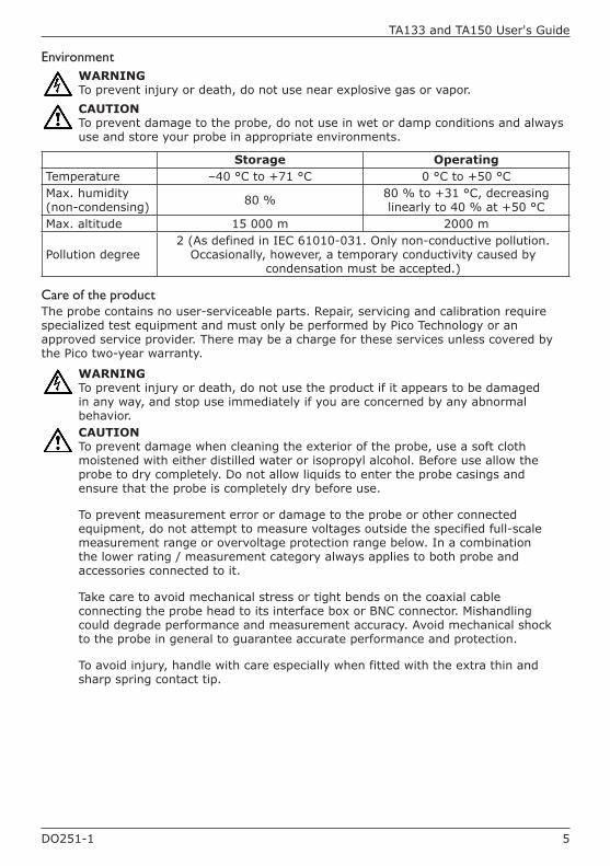
EnvironmentWARNINGTo prevent injury or death, do not use near explosive gas or vapor. CAUTIONTo prevent damage to the probe, do not use in wet or damp conditions and always use and store your probe in appropriate environments.
Storage OperatingTemperature –40 °C to +71 °C 0 °C to +50 °CMax. humidity (non-condensing) 80 % 80 % to +31 °C, decreasing
linearly to 40 % at +50 °CMax. altitude 15 000 m 2000 m
Pollution degree2 (As defined in IEC 61010-031. Only non-conductive pollution.
Occasionally, however, a temporary conductivity caused by condensation must be accepted.)
Care of the productThe probe contains no user-serviceable parts. Repair, servicing and calibration require specialized test equipment and must only be performed by Pico Technology or an approved service provider. There may be a charge for these services unless covered by the Pico two-year warranty.
WARNINGTo prevent injury or death, do not use the product if it appears to be damaged in any way, and stop use immediately if you are concerned by any abnormal behavior.CAUTIONTo prevent damage when cleaning the exterior of the probe, use a soft cloth moistened with either distilled water or isopropyl alcohol. Before use allow the probe to dry completely. Do not allow liquids to enter the probe casings and ensure that the probe is completely dry before use.
To prevent measurement error or damage to the probe or other connected equipment, do not attempt to measure voltages outside the specified full-scale measurement range or overvoltage protection range below. In a combination the lower rating / measurement category always applies to both probe and accessories connected to it.
Take care to avoid mechanical stress or tight bends on the coaxial cable connecting the probe head to its interface box or BNC connector. Mishandling could degrade performance and measurement accuracy. Avoid mechanical shock to the probe in general to guarantee accurate performance and protection.
To avoid injury, handle with care especially when fitted with the extra thin and sharp spring contact tip.
6 DO251-1
TA133 and TA150 User's Guide
About the probe The TA133 and TA150 passive probes set new standards in high-performance probing.
The compact design with only 2.5 mm housing diameter at the probe tip is ideal for measurements of SMT components. It provides a much better visibility of the device under test than conventional 5 mm probe housing designs.
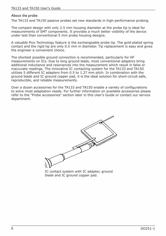
A valuable Pico Technology feature is the exchangeable probe tip. The gold-plated spring contact and the rigid tip are only 0.5 mm in diameter. Tip replacement is easy and gives the engineer a convenient choice.
The shortest possible ground connection is recommended, particularly for HF measurements on ICs. Due to long ground leads, most conventional adaptors bring additional inductance and resonances into the measurement which result in false or inaccurate readings. The innovative IC contacting system for the TA133 and TA150 utilizes 5 different IC adapters from 0.5 to 1.27 mm pitch. In combination with the ground blade and IC ground copper pad, it is the ideal solution for short-circuit-safe, reproducible, and reliable measurements.
Over a dozen accessories for the TA133 and TA150 enable a variety of configurations to solve most adaptation needs. For further information on available accessories please refer to the "Probe accessories" section later in this User's Guide or contact our service department.
IC contact system with IC adapter, ground blade and IC ground copper pad.
7DO251-1
TA133 and TA150 User's Guide
SpecificationsSpecifications marked "typical" are published as general information for the user. The environmental conditions should not exceed the probe's specified limits.
Specifications are subject to change without notice.
Electrical specifications
TA133 TA150Attenuation ratio(1) 10:1 (±2% at DC)Voltage coefficient 0.0025 %/V (typical)Probe bandwidth 500 MHz 350 MHz (–3 dB)Probe risetime 700 ps 1 ns (10%–90%, typical)
(1) Connected to oscilloscope with an input impedance of 1 MΩ ± 1 %.
Electrical characteristics
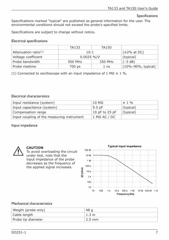
Input resistance (system) 10 MΩ ± 1 %Input capacitance (system) 9.5 pF (typical)Compensation range 10 pF to 25 pF (typical)Input coupling of the measuring instrument 1 MΩ AC / DC
Input impedance
Typical input impedance
10
100
1 k
10 k
100 k
1 M
10 M
100 M
10 100 1 k 10 k 100 k 1 M 10 M 100 M 1 GFrequency [Hz]
|Z| [
ohm
]
Mechanical characteristics
Weight (probe only) 48 gCable length 1.3 mProbe tip diameter 2.5 mm
CAUTIONTo avoid overloading the circuit under test, note that the input impedance of the probe decreases as the frequency of the applied signal increases.
8 DO251-1
TA133 and TA150 User's Guide
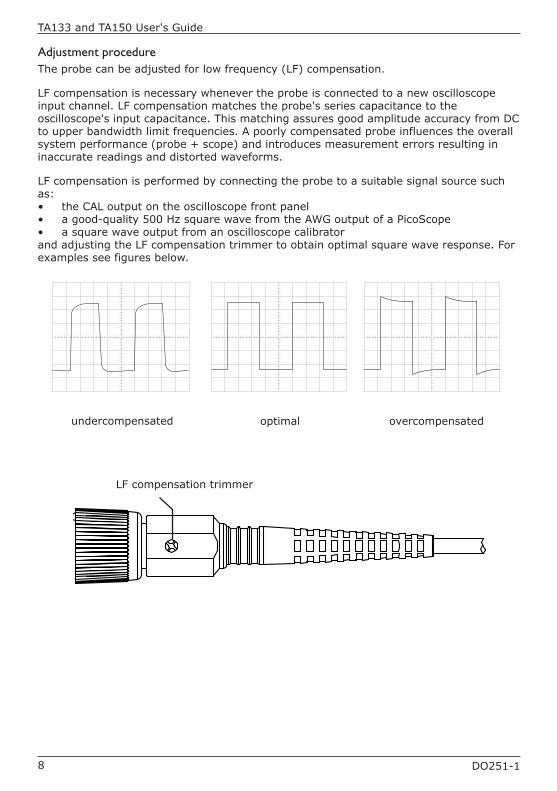
Adjustment procedureThe probe can be adjusted for low frequency (LF) compensation.
LF compensation is necessary whenever the probe is connected to a new oscilloscope input channel. LF compensation matches the probe's series capacitance to the oscilloscope's input capacitance. This matching assures good amplitude accuracy from DC to upper bandwidth limit frequencies. A poorly compensated probe influences the overall system performance (probe + scope) and introduces measurement errors resulting in inaccurate readings and distorted waveforms.
LF compensation is performed by connecting the probe to a suitable signal source such as:• the CAL output on the oscilloscope front panel • a good-quality 500 Hz square wave from the AWG output of a PicoScope• a square wave output from an oscilloscope calibratorand adjusting the LF compensation trimmer to obtain optimal square wave response. For examples see figures below.
LF compensation trimmer
undercompensated optimal overcompensated
9DO251-1
TA133 and TA150 User's Guide
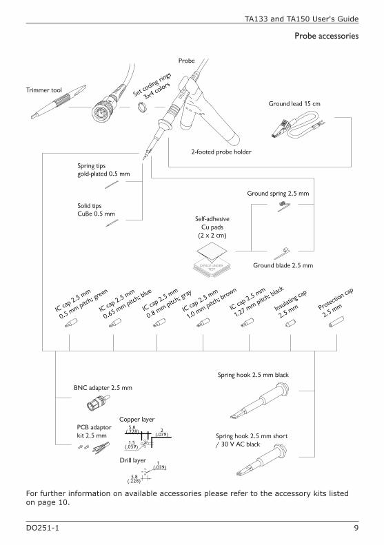
IC cap 2.5 mm
0.65 mm pitch; blue
IC cap 2.5 mm
0.5 mm pitch; green
PCB adaptor kit 2.5 mm
BNC adapter 2.5 mm
Self-adhesiveCu pads
(2 x 2 cm)
Spring hook 2.5 mm black
Protection cap
2.5 mmIC cap 2.5 mm
0.8 mm pitch; gray
IC cap 2.5 mm
1.0 mm pitch; brown
IC cap 2.5 mm
1.27 mm pitch; black
Insulating cap
2.5 mm
Solid tipsCuBe 0.5 mm
Spring tipsgold-plated 0.5 mm
2-footed probe holder
Probe
DEVICE UNDERTEST
Set coding rin
gs
3x4 colors
Ground blade 2.5 mm
Ground spring 2.5 mm
Ground lead 15 cm
Trimmer tool
Spring hook 2.5 mm short / 30 V AC black
Copper layer
Drill layer
5.8(.228)
1(.039)
5.8(.228) 2
(.079)
1.5(.059)
Probe accessories
For further information on available accessories please refer to the accessory kits listed on page 10.
10 DO251-1
TA133 and TA150 User's Guide
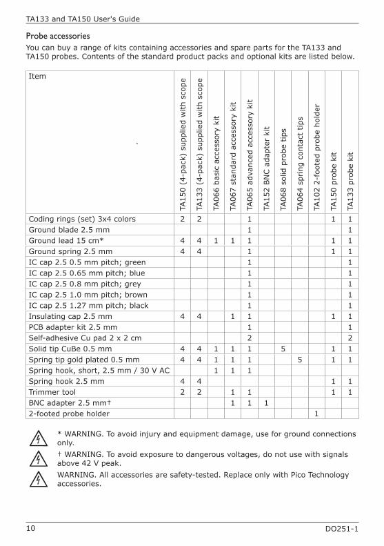
Probe accessoriesYou can buy a range of kits containing accessories and spare parts for the TA133 and TA150 probes. Contents of the standard product packs and optional kits are listed below.
Item
TA15
0 (4
-pac
k) s
uppl
ied
with
sco
pe
TA13
3 (4
-pac
k) s
uppl
ied
with
sco
pe
TA06
6 ba
sic
acce
ssor
y ki
t
TA06
7 st
anda
rd a
cces
sory
kit
TA06
5 ad
vanc
ed a
cces
sory
kit
TA15
2 BN
C a
dapt
er k
it
TA06
8 so
lid p
robe
tip
s
TA06
4 sp
ring
con
tact
tip
s
TA10
2 2-
foot
ed p
robe
hol
der
TA15
0 pr
obe
kit
TA13
3 pr
obe
kit
Coding rings (set) 3x4 colors 2 2 1 1 1Ground blade 2.5 mm 1 1Ground lead 15 cm* 4 4 1 1 1 1 1Ground spring 2.5 mm 4 4 1 1 1IC cap 2.5 0.5 mm pitch; green 1 1IC cap 2.5 0.65 mm pitch; blue 1 1IC cap 2.5 0.8 mm pitch; grey 1 1IC cap 2.5 1.0 mm pitch; brown 1 1IC cap 2.5 1.27 mm pitch; black 1 1Insulating cap 2.5 mm 4 4 1 1 1 1PCB adapter kit 2.5 mm 1 1Self-adhesive Cu pad 2 x 2 cm 2 2Solid tip CuBe 0.5 mm 4 4 1 1 1 5 1 1Spring tip gold plated 0.5 mm 4 4 1 1 1 5 1 1Spring hook, short, 2.5 mm / 30 V AC 1 1 1Spring hook 2.5 mm 4 4 1 1Trimmer tool 2 2 1 1 1 1BNC adapter 2.5 mm† 1 1 12-footed probe holder 1
* WARNING. To avoid injury and equipment damage, use for ground connections only.† WARNING. To avoid exposure to dangerous voltages, do not use with signals above 42 V peak.WARNING. All accessories are safety-tested. Replace only with Pico Technology accessories.
11DO251-1
TA133 and TA150 User's Guide
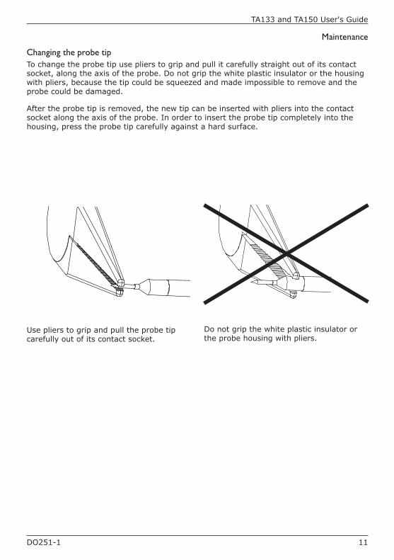
Maintenance
Changing the probe tipTo change the probe tip use pliers to grip and pull it carefully straight out of its contact socket, along the axis of the probe. Do not grip the white plastic insulator or the housing with pliers, because the tip could be squeezed and made impossible to remove and the probe could be damaged.
After the probe tip is removed, the new tip can be inserted with pliers into the contact socket along the axis of the probe. In order to insert the probe tip completely into the housing, press the probe tip carefully against a hard surface.
Use pliers to grip and pull the probe tip carefully out of its contact socket.
Do not grip the white plastic insulator or the probe housing with pliers.
DO251-1
UK headquarters:
Pico TechnologyJames HouseMarlborough RoadColmworth Business ParkEaton SoconSt. NeotsPE19 8YPUnited Kingdom
Tel: +44 (0)1480 396395Fax: +44 (0)1480 396296
[email protected]@picotech.com
www.picotech.com
US headquarters:
Pico Technology North America, Inc.320 N Glenwood Blvd.TylerTX 75702United States
Tel: +1 800 591 2796 (toll free)Fax: +1 620 272 0981
11 Jun 2015