tab 34 - iec contactors & starters (tb03400001e)
TRANSCRIPT
June 2005
CA08102001E For more information visit:
www.EatonElectrical.com
Contents
IEC Contactors & Starters 34-1
34
Vol. 2, Ref. No. [0265]
IEC
Co
nta
cto
rs &
Sta
rte
rs
Description Page
IT.
Electro-Mechanical . . . . . . . . . . . . . . . . . . . . . . . . . . . . . . . . . . . . . . . . . . . 34-2
Contactors — Full Voltage, Non-reversing and Reversing . . . . . . . . . . . .
34-4
Starters — Full Voltage, Non-reversing and Reversing. . . . . . . . . . . . . . .
34-7
IT.
Electro-Mechanical
— Enclosed . . . . . . . . . . . . . . . . . . . . . . . . . . . . . . . . . 34-30
Contactors. . . . . . . . . . . . . . . . . . . . . . . . . . . . . . . . . . . . . . . . . . . . . . . . . . .
34-32
Starters — Non-combination . . . . . . . . . . . . . . . . . . . . . . . . . . . . . . . . . . .
34-34
Starters — Fusible and Non-fusible Combination . . . . . . . . . . . . . . . . . .
34-36
Starters — Combination, HMCP/HMCPE . . . . . . . . . . . . . . . . . . . . . . . . . .
34-44
Modification Codes . . . . . . . . . . . . . . . . . . . . . . . . . . . . . . . . . . . . . . . . . . .
34-49
Miniature Controls . . . . . . . . . . . . . . . . . . . . . . . . . . . . . . . . . . . . . . . . . . . . . . 34-59
Contactors — Non-reversing and Reversing . . . . . . . . . . . . . . . . . . . . . . .
34-61
Freedom
. . . . . . . . . . . . . . . . . . . . . . . . . . . . . . . . . . . . . . . . . . . . . . . . . . . . . .
34-73
Contactors — Non-reversing and Reversing . . . . . . . . . . . . . . . . . . . . . . .
34-75
Starters — Fixed Heater
. . . . . . . . . . . . . . . . . . . . . . . . . . . . . . . . . . . . . . . 34-79
Relays — Fixed Heater Overload . . . . . . . . . . . . . . . . . . . . . . . . . . . . . . . .
34-83
Starters — Interchangeable Heater . . . . . . . . . . . . . . . . . . . . . . . . . . . . . .
34-86
Relays — Interchangeable Heater Overload . . . . . . . . . . . . . . . . . . . . . . .
34-89
Freedom, Full Voltage— Enclosed
. . . . . . . . . . . . . . . . . . . . . . . . . . . . . . . . . .
34-122
Contactors. . . . . . . . . . . . . . . . . . . . . . . . . . . . . . . . . . . . . . . . . . . . . . . . . . .
34-126
Starters — Non-combination . . . . . . . . . . . . . . . . . . . . . . . . . . . . . . . . . . .
34-130
Starters — Fusible Combination . . . . . . . . . . . . . . . . . . . . . . . . . . . . . . . . .
34-138
Starters — Combination, GMCP . . . . . . . . . . . . . . . . . . . . . . . . . . . . . . . .
34-146
IEC Contactors and Starters
�������
June 2005
34-2
For more information visit:
www.EatonElectrical.com
CA08102001E
IEC Contactors & Starters
34
IT.
Electro-Mechanical
Product Family Overview
Vol. 2, Ref. No. [0266]
Product Description
Eaton’s Cutler-Hammer
®
Intelligent Technologies (
IT
.
) Electro-Mechanical line of Contactors and Starters is the result of a substantial engineering, manufacturing and marketing effort involving extensive customer input, combined with new advances in solid-state technology.
IT
.
Electro-Mechanical products have greatly increased functionality, significantly reduced size and utilize the benefits of 24V DC control. The exclusive Pulse Width Modulation (PWM) control and digital microprocessor generate a minimized DC value which reduces energy to the contact block and provides the most compact system available.
Standards and Certifications
■
Designed to meet or exceed UL, IEC and CSA
■
UL Listed: UL File #E1491, Guide #NLDX — Open, UL 508
■
CSA Certified: CSA File #156828, Class #3211 04 Open, C22.2 No. 14-95
■
IEC: A – F Frames, IEC 60947-4-1,EN 60947-4-1
■
45 mm – 76 mm CSA Certified for Elevator Duty
■
CE
■
EMC IEC 61000-4
■
KEMA
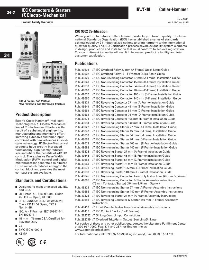
IEC, A Frame, Full Voltage Non-reversing and Reversing Starters
ISO 9002 Certification
When you turn to Eaton’s Cutler-Hammer Products, you turn to quality. The Inter-national Standards Organization (ISO) has established a series of standards acknowledged by 91 industrialized nations to bring harmony to the international quest for quality. The ISO Certification process covers 20 quality system elements in design, production and installation that must conform to achieve registration. This commitment to quality will result in increased product reliability and total customer satisfaction.
Publications
Pub. 49601
IT
.
IEC Overload Relay 27 mm (A-Frame) Quick Setup GuidePub. 49602
IT
.
IEC Overload Relay (B – F Frames) Quick Setup GuidePub. 49320
IT
.
IEC Non-reversing Contactor 27 mm (A-Frame) Installation GuidePub. 49640
IT
.
IEC Non-reversing Contactor 45 mm (B-Frame) Installation GuidePub. 49650
IT
.
IEC Non-reversing Contactor 54 mm (C-Frame) Installation GuidePub. 49660
IT
.
IEC Non-reversing Contactor 76 mm (D-Frame) Installation GuidePub. 49670
IT
.
IEC Non-reversing Contactor 105 mm (E-Frame) Installation GuidePub. 49680
IT
.
IEC Non-reversing Contactor 140 mm (F-Frame) Installation GuidePub. 49321
IT
.
IEC Reversing Contactor 27 mm (A-Frame) Installation GuidePub. 49641
IT
.
IEC Reversing Contactor 45 mm (B-Frame) Installation GuidePub. 49651
IT
.
IEC Reversing Contactor 54 mm (C-Frame) Installation GuidePub. 49661
IT
.
IEC Reversing Contactor 76 mm (D-Frame) Installation GuidePub. 49671
IT
.
IEC Reversing Contactor 105 mm (E-Frame) Installation GuidePub. 49681
IT
.
IEC Reversing Contactor 140 mm (F-Frame) Installation GuidePub. 49322
IT
.
IEC Non-reversing Starter 27 mm (A-Frame) Installation GuidePub. 49642
IT
.
IEC Non-reversing Starter 45 mm (B-Frame) Installation GuidePub. 49652
IT
.
IEC Non-reversing Starter 54 mm (C-Frame) Installation GuidePub. 49662
IT
.
IEC Non-reversing Starter 76 mm (D-Frame) Installation GuidePub. 49672
IT
.
IEC Non-reversing Starter 105 mm (E-Frame) Installation GuidePub. 49682
IT
.
IEC Non-reversing Starter 140 mm (F-Frame) Installation GuidePub. 49323
IT
.
IEC Reversing Starter 27 mm (A-Frame) Installation GuidePub. 49643
IT
.
IEC Reversing Starter 45 mm (B-Frame) Installation GuidePub. 49653
IT
.
IEC Reversing Starter 54 mm (C-Frame) Installation GuidePub. 49663
IT
.
IEC Reversing Starter 76 mm (D-Frame) Installation GuidePub. 49673
IT
.
IEC Reversing Starter 105 mm (E-Frame) Installation GuidePub. 49683
IT
.
IEC Reversing Starter 140 mm (F-Frame) Installation GuidePub. 49645
IT
.
IEC Non-reversing Contactor Assembly Instructions (45 mm & 54 mm)Pub. 49665
IT
.
IEC Non-reversing Contactor & Starter Assembly Instructions (76 mm Contactor/Starter) (45 mm & 54 mm Starter)
Pub. 49325
IT
.
IEC Non-reversing Starter 27 mm (A-Frame) Assembly InstructionsPub. 49685
IT
.
IEC Non-reversing Starter 140 mm (F-Frame) Assembly InstructionsPub. 49326
IT
.
IEC Reversing Starter 27 mm (A-Frame) Assembly InstructionsPub. 49686
IT
.
IEC Reversing Contactor & Starter 140 mm (F-Frame) Assembly Instructions
Pub. 49410
IT
.
Front Mountable Auxiliary Contact Assembly InstructionsPub. 49415
IT
.
IEC Contact Blocks (B – E Frames)Pub. 282782
IT
.
Sinking Control Input ConnectionsPub. 282719
IT
.
Overload Trip/Alarm Output (Sourcing/Sinking)
For copies of these and other publications, contact the Literature Fulfillment Center at 800-957-7050, Fax: 877-840-2371 or find on-line at:www.eatonelectrical.com.
For International, call: (630) 377-9738 (English only), Fax: (630) 377-1753.
June 2005
CA08102001E For more information visit:
www.EatonElectrical.com
34-3IEC Contactors & Starters
34
IT.
Electro-Mechanical
Catalog Number Selection
Vol. 2, Ref. No. [0267]
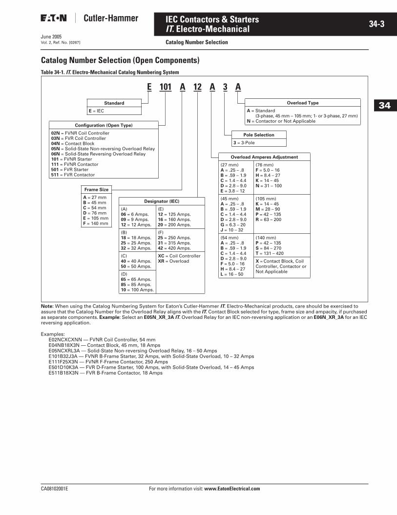
Catalog Number Selection (Open Components)
Table 34-1.
IT.
Electro-Mechanical Catalog Numbering System
Note:
When using the Catalog Numbering System for Eaton’s Cutler-Hammer
IT
.
Electro-Mechanical products, care should be exercised to assure that the Catalog Number for the Overload Relay aligns with the
IT
.
Contact Block selected for type, frame size and ampacity, if purchased as separate components.
Example
: Select an
E05N_XR_3A
IT
.
Overload Relay for an IEC non-reversing application or an
E06N_XR_3A
for an IEC reversing application.
Examples:E02NCXCXNN — FVNR Coil Controller, 54 mmE04NB18X3N — Contact Block, 45 mm, 18 AmpsE05NCXRL3A — Solid-State Non-reversing Overload Relay, 16 – 50 AmpsE101B32J3A — FVNR B-Frame Starter, 32 Amps, with Solid-State Overload, 10 – 32 AmpsE111F25X3N — FVNR F-Frame Contactor, 250 AmpsE501D10K3A — FVR D-Frame Starter, 100 Amps, with Solid-State Overload, 14 – 45 AmpsE511B18X3N — FVR B-Frame Contactor, 18 Amps
Designator (IEC)
(A)06 = 6 Amps.09 = 9 Amps.12 = 12 Amps.
(E)12 = 125 Amps.16 = 160 Amps.20 = 200 Amps.
(B)18 = 18 Amps.25 = 25 Amps.32 = 32 Amps.
(F)25 = 250 Amps.31 = 315 Amps.42 = 420 Amps.
(C)40 = 40 Amps.50 = 50 Amps.
XC = Coil ControllerXR = Overload
(D)65 = 65 Amps.85 = 85 Amps.10 = 100 Amps.
Overload Type
A = Standard(3-phase, 45 mm – 105 mm; 1- or 3-phase, 27 mm)
N = Contactor or Not Applicable
Standard
E = IEC
Configuration (Open Type)
02N = FVNR Coil Controller03N = FVR Coil Controller04N = Contact Block05N = Solid-State Non-reversing Overload Relay06N = Solid-State Reversing Overload Relay101 = FVNR Starter111 = FVNR Contactor501 = FVR Starter511 = FVR Contactor
Frame Size
A = 27 mm B = 45 mm C = 54 mm D = 76 mm E = 105 mmF = 140 mm
Overload Amperes Adjustment
(27 mm)A = .25 – .8B = .59 – 1.9C = 1.4 – 4.4D = 2.8 – 9.0E = 3.8 – 12
(76 mm)F = 5.0 – 16H = 8.4 – 27K = 14 – 45N = 31 – 100
(45 mm)A = .25 – .8B = .59 – 1.9C = 1.4 – 4.4D = 2.8 – 9.0G = 6.3 – 20J = 10 – 32
(105 mm)K = 14 – 45M = 28 – 90P = 42 – 135R = 63 – 200
(54 mm)A = .25 – .8B = .59 – 1.9C = 1.4 – 4.4D = 2.8 – 9.0F = 5.0 – 16H = 8.4 – 27L = 16 – 50
(140 mm)P = 42 – 135S = 84 – 270T = 131 – 420
X = Contact Block, Coil Controller, Contactor or Not Applicable
Pole Selection
3 = 3-Pole
E 101 A 12 A 3 A
June 2005
34-4
For more information visit: www.EatonElectrical.com CA08102001E
IEC Contactors & Starters
34
IT. Electro-MechanicalContactors — Full Voltage, Non-reversing and Reversing Vol. 2, Ref. No. [0268]
ContentsDescription Page
Product Family Overview
Product Description. . . . . . . 34-2
Standards andCertifications . . . . . . . . . . . 34-2
Publications . . . . . . . . . . . . . 34-2
Catalog NumberSelection . . . . . . . . . . . . . . 34-3
Contactors — Non-reversingand Reversing
Product Description. . . . . . . 34-4
Application Description. . . . 34-4
Features . . . . . . . . . . . . . . . . 34-4
Product Selection . . . . . . . . 34-5
Technical Data andSpecifications . . . . . . . . . . . . . 34-14
Accessories . . . . . . . . . . . . . . . . 34-18
Auxiliary Contacts . . . . . . . . 34-20
Renewal Parts. . . . . . . . . . . . . . 34-22
Wiring Diagrams. . . . . . . . . . . . 34-23
Dimensions . . . . . . . . . . . . . . . . 34-24
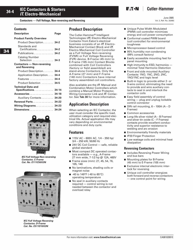
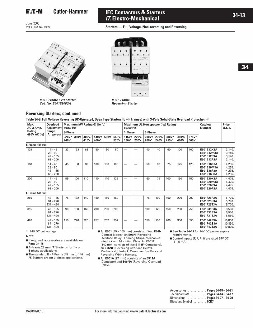
IEC Full Voltage Reversing Contactor, D-FrameCat. No. E511D10X3N
IEC Full Voltage Non-reversing Contactor, C-FrameCat. No. E111C50X3N
Product DescriptionThe Cutler-Hammer® Intelligent Technologies (IT.) Electro-Mechanical Contactor from Eaton’s electrical business consists of an IT. Electro-Mechanical Contact Block and IT. Electro-Mechanical Coil Controller as a Full Voltage Non-reversing (FVNR) or Full Voltage Reversing (FVR) device. B-Frame (45 mm) to E-Frame (105 mm) Contact Blocks combined with Coil Controllers (factory or field assembled) are stand-alone Contactors. Only the A-Frame (27 mm) and F-Frame (140 mm) Contactors have internal factory assembled coil controllers.
Also available are the IT. Manual and Combination Motor Controllers which combine a Manual Motor Protector, Wiring Connector Link and IT. Contac-tor. See Tab 38 for more information.
Application DescriptionWhen selecting an IEC Contactor, the user must consider the specific load, utilization category and required elec-trical life. Actual application life may vary depending on environmental conditions and duty cycle.
Features■ 115V AC – 600V AC, 1/4 – 350 hp/
3/4 – 250 kW, 50/60 Hz■ 24V DC Coil Control — safe, reliable
global standard■ Most compact DC operated contac-
tors available — e.g., A-Frame 27 mm wide, 7-1/2 hp @ 12A, 460V
■ Frame sizes (mm): 27, 45, 54, 76, 105, 140
■ No laminations, shading coils or magnet noise
■ -40 to 149°F (-40 to 65°C) operating temperature
■ No seal in auxiliary contacts required — control wiring is not needed between the contactor and overload relay
■ Unique Pulse Width Modulated (PWM) coil controller minimizes energy and coil power consumption
■ Conformal coated PWM board (coil controller) for environmental toughness
■ Microprocessor-based control■ 95% humidity non-condensing
(99% consult factory)■ Easily accessible mounting feet for
panel mounting■ High immunity to ESD, harmonics —
minimal Total Harmonic Distortion■ Front and side mounted Auxiliary
Contacts: 1NO, 1NC, 2NO, 2NC, 1NO/1NC and logic level
■ Built-in logic to provide either 2- or 3-wire control, eliminating the need to provide and wire auxiliary con-tacts to seal in and interlock the contactor coils
■ Easy field assembly of control wiring — plug and unplug lockable control connector
■ DIN rail mounting, 6 – 100A (A – D Frames)
■ Common accessories■ Long-life silver nickel (A – B Frames)
and silver tin oxide (C – F Frames) contacts provide excellent conduc-tivity and superior resistance to welding and arc erosion
■ Environmentally friendly materials■ IP20 Finger Protection■ Low wattage coils and minimal heat
dissipation
Reversing Contactors■ Includes Reversing Power Wiring
and bus bars■ Mounting plates for B-Frame
(45 mm) to E-Frame (105 mm)■ Exclusive internal electronic inter-
lock for reversing■ Unique coil controller energizes
both forward and reverse contactors — one control point for wiring
June 2005
CA08102001E For more information visit: www.EatonElectrical.com
34-5IEC Contactors & Starters
34
IT. Electro-MechanicalContactors — Full Voltage, Non-reversing and ReversingVol. 2, Ref. No. [0269]
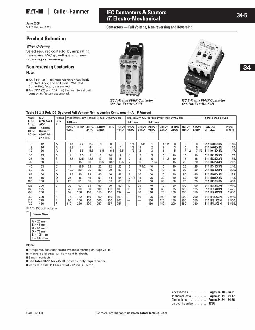
Product SelectionWhen Ordering Select required contactor by amp rating, frame size, kW/hp, voltage and non-reversing or reversing.
Non-reversing ContactorsNote:
■ An E111 (45 – 105 mm) consists of an E04N (Contact Block) and an E02N (FVNR Coil Controller), factory assembled.
■ An E111 (27 and 140 mm) has an internal coil controller, factory assembled.
Table 34-2. 3-Pole DC-Operated Full Voltage Non-reversing Contactors � (A – F Frames)
� 24V DC coil voltage. �
Note:
■ If required, accessories are available starting on Page 34-18.■ Integral solid-state auxiliary hold-in circuit.■ 3 main contacts.■ See Table 34-11 for 24V DC power supply requirements.■ Control inputs (P, F) are rated 24V DC (3 – 5 mA).
IEC A-Frame FVNR ContactorCat. No. E111A12X3N
IEC B-Frame FVNR Contactor Cat. No. E111B32X3N
Max. AC-3Amp.Rating480V AC (le)
IEC 60947-4-1AC-1 ThermalCurrent 480V ACand (Ith)
FrameSize�
Maximum kW Rating @ Ue (V) 50/60 Hz Maximum UL Horsepower (hp) 50/60 Hz 3-Pole Open Type
3-Phase 1-Phase 3-Phase
220V/240V
380V 400V/415V
440V/460V
500V 550V/575V
115V/120V
220V/230V
200V/208V
230V/240V
380V/415V
460V/480V
575V/600V
CatalogNumber
Price U.S. $
69
12
121620
AAA
1.12.23
2.245.5
2.245.5
346.5
346.5
346.5
1/41/31/2
1/212
123
1-1/223
335
357-1/2
357-1/2
E111A06X3NE111A09X3NE111A12X3N
113.115.147.
182532
254050
BBB
45.59
7.512.515
912.515
91318.5
101518.5
111518.5
122
335
557-1/2
57-1/2
10
101015
101520
101520
E111B18X3NE111B25X3NE111B32X3N
167.185.212.
4050
6385
CC
1112.5
18.522
2225
2230
2230
2533
33
7-1/210
1015
1015
2025
2530
2530
E111C40X3NE111C50X3N
246.268.
6585
100
100115130
DDD
18.52525
304551
334555
405159
405159
455563
57-1/2
10
101520
202530
203030
405050
506075
506075
E111D65X3NE111D85X3NE111D10X3N
393.443.650.
125160200
200225250
EEE
334559
6380
100
6380
110
80100110
80100110
80100132
1015—
253040
405060
406075
6075
100
100125150
100125150
E111E12X3NE111E16X3NE111E20X3N
1,010.1,425.1,600.
250315420
300375450
F F F
7590
110
132160220
140160220
160200257
160200257
160200257
———
50——
75100150
100125150
150150200
200250350
200250350
E111F25X3NE111F31X3NE111F42X3N
2,080.2,550.3,555.
Frame Size
A = 27 mm B = 45 mm C = 54 mm D = 76 mm E = 105 mmF = 140 mm
Accessories . . . . . . . . . . . . . Pages 34-18 – 34-21Technical Data . . . . . . . . . . . Pages 34-14 – 34-17Dimensions . . . . . . . . . . . . . . Pages 34-24 – 34-26Discount Symbol . . . . . . . . . 1CD7
June 2005
34-6
For more information visit: www.EatonElectrical.com CA08102001E
IEC Contactors & Starters
34
IT. Electro-MechanicalContactors — Full Voltage, Non-reversing and Reversing Vol. 2, Ref. No. [0270]
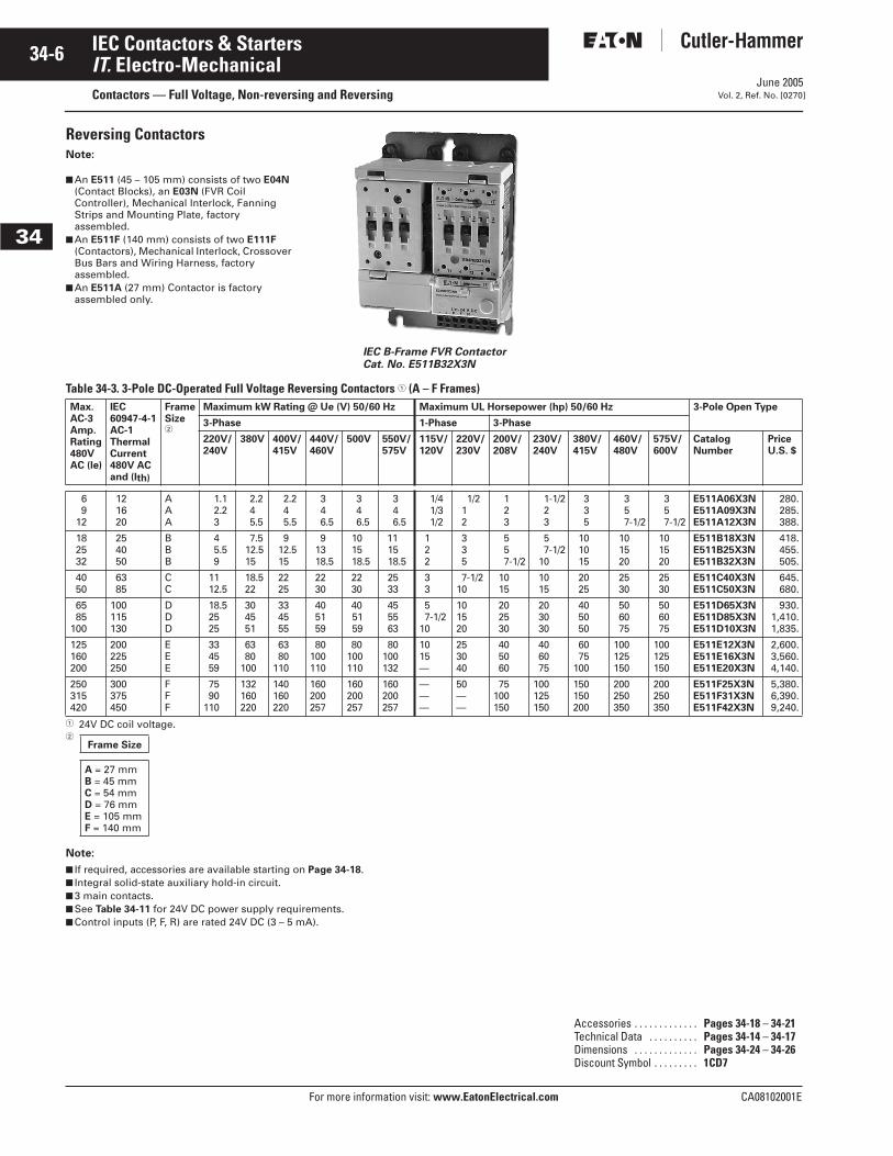
Reversing ContactorsNote:
■ An E511 (45 – 105 mm) consists of two E04N (Contact Blocks), an E03N (FVR Coil Controller), Mechanical Interlock, Fanning Strips and Mounting Plate, factory assembled.
■ An E511F (140 mm) consists of two E111F (Contactors), Mechanical Interlock, Crossover Bus Bars and Wiring Harness, factory assembled.
■ An E511A (27 mm) Contactor is factory assembled only.
Table 34-3. 3-Pole DC-Operated Full Voltage Reversing Contactors � (A – F Frames)
� 24V DC coil voltage. �
Note:
■ If required, accessories are available starting on Page 34-18.■ Integral solid-state auxiliary hold-in circuit.■ 3 main contacts.■ See Table 34-11 for 24V DC power supply requirements.■ Control inputs (P, F, R) are rated 24V DC (3 – 5 mA).
IEC B-Frame FVR ContactorCat. No. E511B32X3N
Max. AC-3Amp.Rating480V AC (le)
IEC 60947-4-1AC-1 ThermalCurrent 480V ACand (Ith)
FrameSize�
Maximum kW Rating @ Ue (V) 50/60 Hz Maximum UL Horsepower (hp) 50/60 Hz 3-Pole Open Type
3-Phase 1-Phase 3-Phase
220V/240V
380V 400V/415V
440V/460V
500V 550V/575V
115V/120V
220V/230V
200V/208V
230V/240V
380V/415V
460V/480V
575V/600V
Catalog Number
Price U.S. $
69
12
121620
AAA
1.12.23
2.245.5
2.245.5
346.5
346.5
346.5
1/41/31/2
1/212
123
1-1/223
335
357-1/2
357-1/2
E511A06X3NE511A09X3NE511A12X3N
280.285.388.
182532
254050
BBB
45.59
7.512.515
912.515
91318.5
101518.5
111518.5
122
335
557-1/2
57-1/2
10
101015
101520
101520
E511B18X3NE511B25X3NE511B32X3N
418.455.505.
4050
6385
CC
1112.5
18.522
2225
2230
2230
2533
33
7-1/210
1015
1015
2025
2530
2530
E511C40X3NE511C50X3N
645.680.
6585
100
100115130
DDD
18.52525
304551
334555
405159
405159
455563
57-1/2
10
101520
202530
203030
405050
506075
506075
E511D65X3NE511D85X3NE511D10X3N
930.1,410.1,835.
125160200
200225250
EEE
334559
6380
100
6380
110
80100110
80100110
80100132
1015—
253040
405060
406075
6075
100
100125150
100125150
E511E12X3NE511E16X3NE511E20X3N
2,600.3,560.4,140.
250315420
300375450
F F F
7590
110
132160220
140160220
160200257
160200257
160200257
———
50——
75100150
100125150
150150200
200250350
200250350
E511F25X3NE511F31X3NE511F42X3N
5,380.6,390.9,240.
Frame Size
A = 27 mm B = 45 mm C = 54 mm D = 76 mm E = 105 mmF = 140 mm
Accessories . . . . . . . . . . . . . Pages 34-18 – 34-21Technical Data . . . . . . . . . . Pages 34-14 – 34-17Dimensions . . . . . . . . . . . . . Pages 34-24 – 34-26Discount Symbol . . . . . . . . . 1CD7
June 2005
CA08102001E For more information visit: www.EatonElectrical.com
34-7IEC Contactors & Starters
34
IT. Electro-MechanicalStarters — Full Voltage, Non-reversing and ReversingVol. 2, Ref. No. [0271]
ContentsDescription Page
Product Family Overview
Product Description . . . . . . 34-2
Standards andCertifications . . . . . . . . . . 34-2
Publications . . . . . . . . . . . . 34-2
Catalog NumberSelection . . . . . . . . . . . . . 34-3
Starters — Non-reversingand Reversing
Product Description . . . . . . 34-7
Features . . . . . . . . . . . . . . . 34-7
Product Selection. . . . . . . . 34-8
Technical Data andSpecifications . . . . . . . . . . . . 34-14
Accessories . . . . . . . . . . . . . . . 34-18
Auxiliary Contacts . . . . . . . 34-20
Renewal Parts . . . . . . . . . . . . . 34-22
Wiring Diagrams . . . . . . . . . . . 34-23
Dimensions . . . . . . . . . . . . . . . 34-24
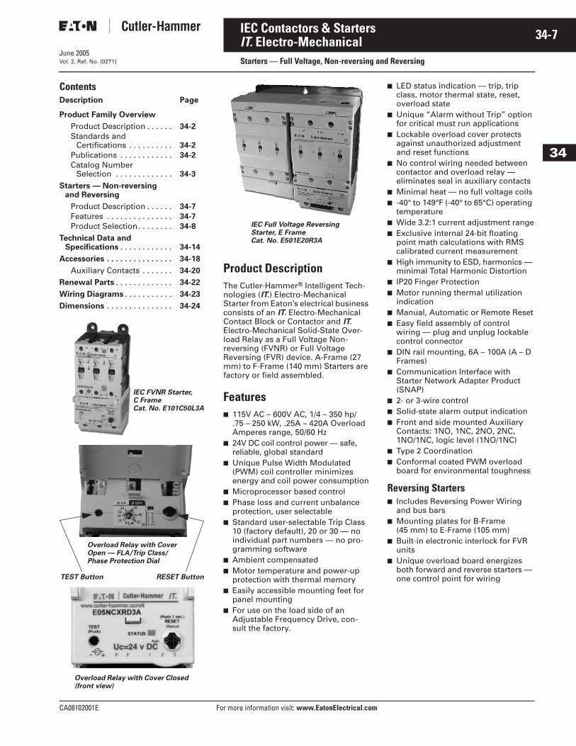
Product DescriptionThe Cutler-Hammer® Intelligent Tech-nologies (IT.) Electro-Mechanical Starter from Eaton’s electrical business consists of an IT. Electro-Mechanical Contact Block or Contactor and IT. Electro-Mechanical Solid-State Over-load Relay as a Full Voltage Non-reversing (FVNR) or Full Voltage Reversing (FVR) device. A-Frame (27 mm) to F-Frame (140 mm) Starters are factory or field assembled.
Features■ 115V AC – 600V AC, 1/4 – 350 hp/
.75 – 250 kW, .25A – 420A Overload Amperes range, 50/60 Hz
■ 24V DC coil control power — safe, reliable, global standard
■ Unique Pulse Width Modulated (PWM) coil controller minimizes energy and coil power consumption
■ Microprocessor based control■ Phase loss and current unbalance
protection, user selectable■ Standard user-selectable Trip Class
10 (factory default), 20 or 30 — no individual part numbers — no pro-gramming software
■ Ambient compensated■ Motor temperature and power-up
protection with thermal memory■ Easily accessible mounting feet for
panel mounting■ For use on the load side of an
Adjustable Frequency Drive, con-sult the factory.
■ LED status indication — trip, trip class, motor thermal state, reset, overload state
■ Unique “Alarm without Trip” option for critical must run applications
■ Lockable overload cover protects against unauthorized adjustment and reset functions
■ No control wiring needed between contactor and overload relay — eliminates seal in auxiliary contacts
■ Minimal heat — no full voltage coils■ -40° to 149°F (-40° to 65°C) operating
temperature■ Wide 3.2:1 current adjustment range■ Exclusive internal 24-bit floating
point math calculations with RMS calibrated current measurement
■ High immunity to ESD, harmonics — minimal Total Harmonic Distortion
■ IP20 Finger Protection■ Motor running thermal utilization
indication■ Manual, Automatic or Remote Reset■ Easy field assembly of control
wiring — plug and unplug lockable control connector
■ DIN rail mounting, 6A – 100A (A – D Frames)
■ Communication Interface with Starter Network Adapter Product (SNAP)
■ 2- or 3-wire control■ Solid-state alarm output indication■ Front and side mounted Auxiliary
Contacts: 1NO, 1NC, 2NO, 2NC, 1NO/1NC, logic level (1NO/1NC)
■ Type 2 Coordination■ Conformal coated PWM overload
board for environmental toughness
Reversing Starters■ Includes Reversing Power Wiring
and bus bars■ Mounting plates for B-Frame
(45 mm) to E-Frame (105 mm)■ Built-in electronic interlock for FVR
units■ Unique overload board energizes
both forward and reverse starters — one control point for wiring
IEC FVNR Starter, C FrameCat. No. E101C50L3A
Overload Relay with Cover Open — FLA/Trip Class/Phase Protection Dial
TEST Button RESET Button
Overload Relay with Cover Closed (front view)
IEC Full Voltage ReversingStarter, E FrameCat. No. E501E20R3A
June 2005
34-8
For more information visit: www.EatonElectrical.com CA08102001E
IEC Contactors & Starters
34
IT. Electro-MechanicalStarters — Full Voltage, Non-reversing and Reversing Vol. 2, Ref. No. [0272]
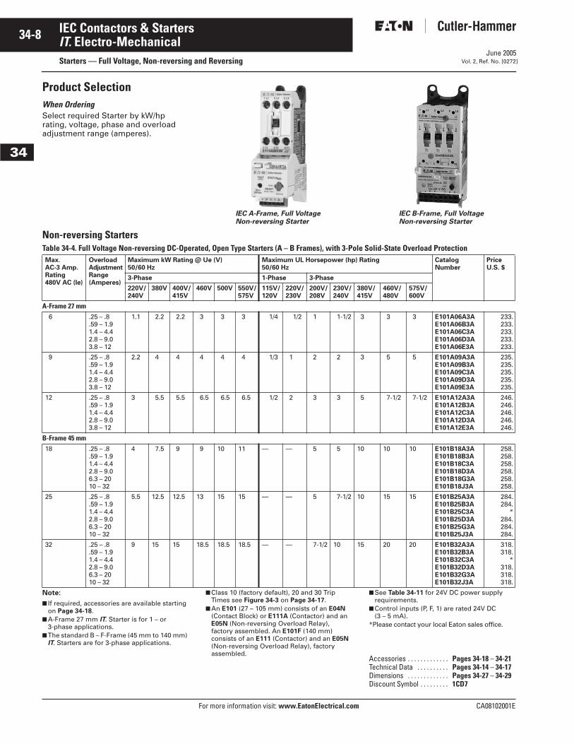
Product SelectionWhen Ordering Select required Starter by kW/hp rating, voltage, phase and overload adjustment range (amperes).
Non-reversing StartersTable 34-4. Full Voltage Non-reversing DC-Operated, Open Type Starters (A – B Frames), with 3-Pole Solid-State Overload Protection
Note:
■ If required, accessories are available starting on Page 34-18.
■ A-Frame 27 mm IT. Starter is for 1 – or 3-phase applications.
■ The standard B – F-Frame (45 mm to 140 mm) IT. Starters are for 3-phase applications.
■ Class 10 (factory default), 20 and 30 Trip Times see Figure 34-3 on Page 34-17.
■ An E101 (27 – 105 mm) consists of an E04N (Contact Block) or E111A (Contactor) and an E05N (Non-reversing Overload Relay), factory assembled. An E101F (140 mm) consists of an E111 (Contactor) and an E05N (Non-reversing Overload Relay), factory assembled.
■ See Table 34-11 for 24V DC power supply requirements.
■ Control inputs (P, F, 1) are rated 24V DC (3 – 5 mA).
*Please contact your local Eaton sales office.
IEC A-Frame, Full Voltage Non-reversing Starter
IEC B-Frame, Full Voltage Non-reversing Starter
Max. AC-3 Amp.Rating480V AC (le)
OverloadAdjustmentRange(Amperes)
Maximum kW Rating @ Ue (V)50/60 Hz
Maximum UL Horsepower (hp) Rating 50/60 Hz
CatalogNumber
PriceU.S. $
3-Phase 1-Phase 3-Phase
220V/240V
380V 400V/415V
460V 500V 550V/575V
115V/120V
220V/230V
200V/208V
230V/240V
380V/415V
460V/480V
575V/600V
A-Frame 27 mm6 .25 – .8
.59 – 1.91.4 – 4.42.8 – 9.03.8 – 12
1.1 2.2 2.2 3 3 3 1/4 1/2 1 1-1/2 3 3 3 E101A06A3AE101A06B3AE101A06C3AE101A06D3AE101A06E3A
233.233.233.233.233.
9 .25 – .8.59 – 1.91.4 – 4.42.8 – 9.03.8 – 12
2.2 4 4 4 4 4 1/3 1 2 2 3 5 5 E101A09A3AE101A09B3AE101A09C3AE101A09D3AE101A09E3A
235.235.235.235.235.
12 .25 – .8.59 – 1.91.4 – 4.42.8 – 9.03.8 – 12
3 5.5 5.5 6.5 6.5 6.5 1/2 2 3 3 5 7-1/2 7-1/2 E101A12A3AE101A12B3AE101A12C3AE101A12D3AE101A12E3A
246.246.246.246.246.
B-Frame 45 mm18 .25 – .8
.59 – 1.91.4 – 4.42.8 – 9.06.3 – 2010 – 32
4 7.5 9 9 10 11 — — 5 5 10 10 10 E101B18A3AE101B18B3AE101B18C3AE101B18D3AE101B18G3AE101B18J3A
258.258.258.258.258.258.
25 .25 – .8.59 – 1.91.4 – 4.42.8 – 9.06.3 – 2010 – 32
5.5 12.5 12.5 13 15 15 — — 5 7-1/2 10 15 15 E101B25A3AE101B25B3AE101B25C3AE101B25D3AE101B25G3AE101B25J3A
284.284.
*284.284.284.
32 .25 – .8.59 – 1.91.4 – 4.42.8 – 9.06.3 – 2010 – 32
9 15 15 18.5 18.5 18.5 — — 7-1/2 10 15 20 20 E101B32A3AE101B32B3AE101B32C3AE101B32D3AE101B32G3AE101B32J3A
318.318.
*318.318.318.
Accessories . . . . . . . . . . . . . Pages 34-18 – 34-21Technical Data . . . . . . . . . . Pages 34-14 – 34-17Dimensions . . . . . . . . . . . . . Pages 34-27 – 34-29Discount Symbol . . . . . . . . . 1CD7
June 2005
CA08102001E For more information visit: www.EatonElectrical.com
34-9IEC Contactors & Starters
34
IT. Electro-MechanicalStarters — Full Voltage, Non-reversing and ReversingVol. 2, Ref. No. [0273]
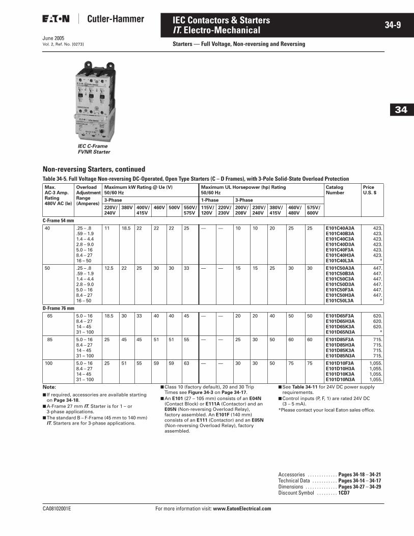
Non-reversing Starters, continuedTable 34-5. Full Voltage Non-reversing DC-Operated, Open Type Starters (C – D Frames), with 3-Pole Solid-State Overload Protection
Note:
■ If required, accessories are available starting on Page 34-18.
■ A-Frame 27 mm IT. Starter is for 1 – or 3-phase applications.
■ The standard B – F-Frame (45 mm to 140 mm) IT. Starters are for 3-phase applications.
■ Class 10 (factory default), 20 and 30 Trip Times see Figure 34-3 on Page 34-17.
■ An E101 (27 – 105 mm) consists of an E04N (Contact Block) or E111A (Contactor) and an E05N (Non-reversing Overload Relay), factory assembled. An E101F (140 mm) consists of an E111 (Contactor) and an E05N (Non-reversing Overload Relay), factory assembled.
■ See Table 34-11 for 24V DC power supply requirements.
■ Control inputs (P, F, 1) are rated 24V DC (3 – 5 mA).
*Please contact your local Eaton sales office.
IEC C-FrameFVNR Starter
Max. AC-3 Amp.Rating480V AC (le)
OverloadAdjustmentRange(Amperes)
Maximum kW Rating @ Ue (V)50/60 Hz
Maximum UL Horsepower (hp) Rating 50/60 Hz
CatalogNumber
PriceU.S. $
3-Phase 1-Phase 3-Phase
220V/240V
380V 400V/415V
460V 500V 550V/575V
115V/120V
220V/230V
200V/208V
230V/240V
380V/415V
460V/480V
575V/600V
C-Frame 54 mm40 .25 – .8
.59 – 1.91.4 – 4.42.8 – 9.05.0 – 168.4 – 2716 – 50
11 18.5 22 22 22 25 — — 10 10 20 25 25 E101C40A3AE101C40B3AE101C40C3AE101C40D3AE101C40F3AE101C40H3AE101C40L3A
423.423.423.423.423.423.
*
50 .25 – .8.59 – 1.91.4 – 4.42.8 – 9.05.0 – 168.4 – 2716 – 50
12.5 22 25 30 30 33 — — 15 15 25 30 30 E101C50A3AE101C50B3AE101C50C3AE101C50D3AE101C50F3AE101C50H3AE101C50L3A
447.447.447.447.447.447.
*
D-Frame 76 mm65 5.0 – 16
8.4 – 2714 – 4531 – 100
18.5 30 33 40 40 45 — — 20 20 40 50 50 E101D65F3AE101D65H3AE101D65K3AE101D65N3A
620.620.620.
*
85 5.0 – 168.4 – 2714 – 4531 – 100
25 45 45 51 51 55 — — 25 30 50 60 60 E101D85F3AE101D85H3AE101D85K3AE101D85N3A
715.715.715.715.
100 5.0 – 168.4 – 2714 – 4531 – 100
25 51 55 59 59 63 — — 30 30 50 75 75 E101D10F3AE101D10H3AE101D10K3AE101D10N3A
1,055.1,055.1,055.1,055.
Accessories . . . . . . . . . . . . . Pages 34-18 – 34-21Technical Data . . . . . . . . . . . Pages 34-14 – 34-17Dimensions . . . . . . . . . . . . . . Pages 34-27 – 34-29Discount Symbol . . . . . . . . . 1CD7
June 2005
34-10
For more information visit: www.EatonElectrical.com CA08102001E
IEC Contactors & Starters
34
IT. Electro-MechanicalStarters — Full Voltage, Non-reversing and Reversing Vol. 2, Ref. No. [0274]
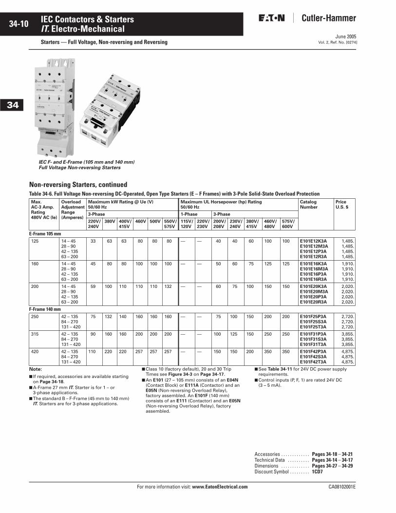
Non-reversing Starters, continuedTable 34-6. Full Voltage Non-reversing DC-Operated, Open Type Starters (E – F Frames) with 3-Pole Solid-State Overload Protection
Note:
■ If required, accessories are available starting on Page 34-18.
■ A-Frame 27 mm IT. Starter is for 1 – or 3-phase applications.
■ The standard B – F-Frame (45 mm to 140 mm) IT. Starters are for 3-phase applications.
■ Class 10 (factory default), 20 and 30 Trip Times see Figure 34-3 on Page 34-17.
■ An E101 (27 – 105 mm) consists of an E04N (Contact Block) or E111A (Contactor) and an E05N (Non-reversing Overload Relay), factory assembled. An E101F (140 mm) consists of an E111 (Contactor) and an E05N (Non-reversing Overload Relay), factory assembled.
■ See Table 34-11 for 24V DC power supply requirements.
■ Control inputs (P, F, 1) are rated 24V DC (3 – 5 mA).
IEC F- and E-Frame (105 mm and 140 mm) Full Voltage Non-reversing Starters
Max. AC-3 Amp.Rating480V AC (le)
OverloadAdjustmentRange(Amperes)
Maximum kW Rating @ Ue (V)50/60 Hz
Maximum UL Horsepower (hp) Rating 50/60 Hz
CatalogNumber
PriceU.S. $
3-Phase 1-Phase 3-Phase
220V/240V
380V 400V/415V
460V 500V 550V/575V
115V/120V
220V/230V
200V/208V
230V/240V
380V/415V
460V/480V
575V/600V
E-Frame 105 mm125 14 – 45
28 – 9042 – 13563 – 200
33 63 63 80 80 80 — — 40 40 60 100 100 E101E12K3AE101E12M3AE101E12P3AE101E12R3A
1,485.1,485.1,485.1,485.
160 14 – 4528 – 9042 – 13563 – 200
45 80 80 100 100 100 — — 50 60 75 125 125 E101E16K3AE101E16M3AE101E16P3AE101E16R3A
1,910.1,910.1,910.1,910.
200 14 – 4528 – 9042 – 13563 – 200
59 100 110 110 110 132 — — 60 75 100 150 150 E101E20K3AE101E20M3AE101E20P3AE101E20R3A
2,020.2,020.2,020.2,020.
F-Frame 140 mm 250 42 – 135
84 – 270131 – 420
75 132 140 160 160 160 — — 75 100 150 200 200 E101F25P3AE101F25S3AE101F25T3A
2,720.2,720.2,720.
315 42 – 13584 – 270131 – 420
90 160 160 200 200 200 — — 100 125 150 250 250 E101F31P3AE101F31S3AE101F31T3A
3,855.3,855.3,855.
420 42 – 13584 – 270131 – 420
110 220 220 257 257 257 — — 150 150 200 350 350 E101F42P3AE101F42S3AE101F42T3A
4,875.4,875.4,875.
Accessories . . . . . . . . . . . . . Pages 34-18 – 34-21Technical Data . . . . . . . . . . Pages 34-14 – 34-17Dimensions . . . . . . . . . . . . . Pages 34-27 – 34-29Discount Symbol . . . . . . . . . 1CD7
June 2005
CA08102001E For more information visit: www.EatonElectrical.com
34-11IEC Contactors & Starters
34
IT. Electro-MechanicalStarters — Full Voltage, Non-reversing and ReversingVol. 2, Ref. No. [0275]
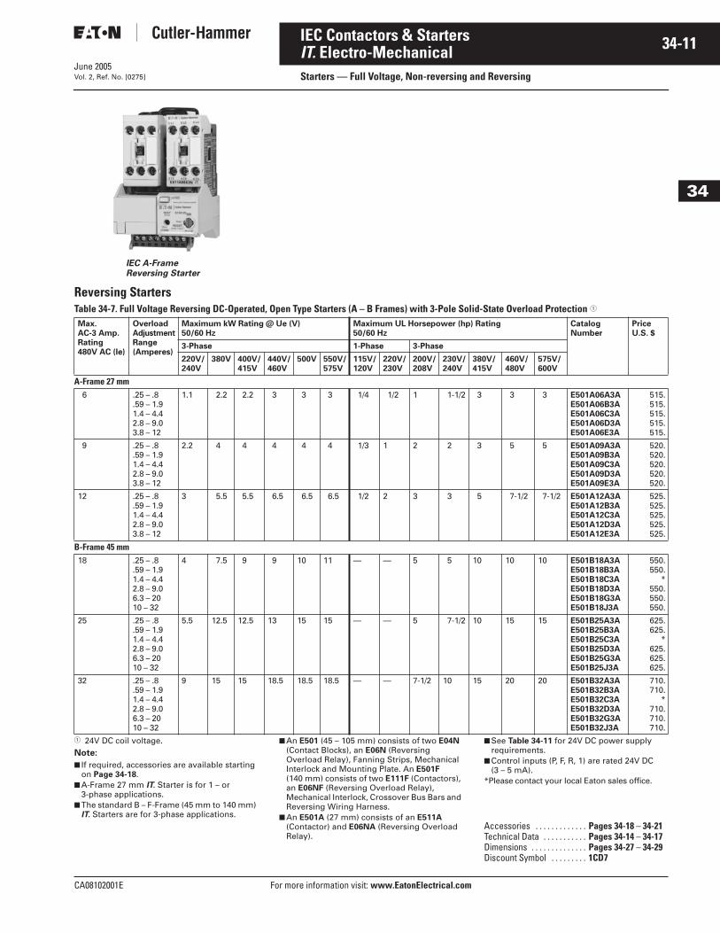
Reversing StartersTable 34-7. Full Voltage Reversing DC-Operated, Open Type Starters (A – B Frames) with 3-Pole Solid-State Overload Protection �
� 24V DC coil voltage. Note:
■ If required, accessories are available starting on Page 34-18.
■ A-Frame 27 mm IT. Starter is for 1 – or 3-phase applications.
■ The standard B – F-Frame (45 mm to 140 mm) IT. Starters are for 3-phase applications.
■ An E501 (45 – 105 mm) consists of two E04N (Contact Blocks), an E06N (Reversing Overload Relay), Fanning Strips, Mechanical Interlock and Mounting Plate. An E501F (140 mm) consists of two E111F (Contactors), an E06NF (Reversing Overload Relay), Mechanical Interlock, Crossover Bus Bars and Reversing Wiring Harness.
■ An E501A (27 mm) consists of an E511A (Contactor) and E06NA (Reversing Overload Relay).
■ See Table 34-11 for 24V DC power supply requirements.
■ Control inputs (P, F, R, 1) are rated 24V DC (3 – 5 mA).
*Please contact your local Eaton sales office.
IEC A-Frame Reversing Starter
Max. AC-3 Amp.Rating480V AC (le)
OverloadAdjustmentRange(Amperes)
Maximum kW Rating @ Ue (V)50/60 Hz
Maximum UL Horsepower (hp) Rating 50/60 Hz
CatalogNumber
PriceU.S. $
3-Phase 1-Phase 3-Phase
220V/240V
380V 400V/415V
440V/460V
500V 550V/575V
115V/120V
220V/230V
200V/208V
230V/240V
380V/415V
460V/480V
575V/600V
A-Frame 27 mm6 .25 – .8
.59 – 1.91.4 – 4.42.8 – 9.03.8 – 12
1.1 2.2 2.2 3 3 3 1/4 1/2 1 1-1/2 3 3 3 E501A06A3AE501A06B3AE501A06C3AE501A06D3AE501A06E3A
515.515.515.515.515.
9 .25 – .8.59 – 1.91.4 – 4.42.8 – 9.03.8 – 12
2.2 4 4 4 4 4 1/3 1 2 2 3 5 5 E501A09A3AE501A09B3AE501A09C3AE501A09D3AE501A09E3A
520.520.520.520.520.
12 .25 – .8.59 – 1.91.4 – 4.42.8 – 9.03.8 – 12
3 5.5 5.5 6.5 6.5 6.5 1/2 2 3 3 5 7-1/2 7-1/2 E501A12A3AE501A12B3AE501A12C3AE501A12D3AE501A12E3A
525.525.525.525.525.
B-Frame 45 mm18 .25 – .8
.59 – 1.91.4 – 4.42.8 – 9.06.3 – 2010 – 32
4 7.5 9 9 10 11 — — 5 5 10 10 10 E501B18A3AE501B18B3AE501B18C3AE501B18D3AE501B18G3AE501B18J3A
550.550.
*550.550.550.
25 .25 – .8.59 – 1.91.4 – 4.42.8 – 9.06.3 – 2010 – 32
5.5 12.5 12.5 13 15 15 — — 5 7-1/2 10 15 15 E501B25A3AE501B25B3AE501B25C3AE501B25D3AE501B25G3AE501B25J3A
625.625.
*625.625.625.
32 .25 – .8.59 – 1.91.4 – 4.42.8 – 9.06.3 – 2010 – 32
9 15 15 18.5 18.5 18.5 — — 7-1/2 10 15 20 20 E501B32A3AE501B32B3AE501B32C3AE501B32D3AE501B32G3AE501B32J3A
710.710.
*710.710.710.
Accessories . . . . . . . . . . . . . Pages 34-18 – 34-21Technical Data . . . . . . . . . . . Pages 34-14 – 34-17Dimensions . . . . . . . . . . . . . . Pages 34-27 – 34-29Discount Symbol . . . . . . . . . 1CD7
June 2005
34-12
For more information visit: www.EatonElectrical.com CA08102001E
IEC Contactors & Starters
34
IT. Electro-MechanicalStarters — Full Voltage, Non-reversing and Reversing Vol. 2, Ref. No. [0276]
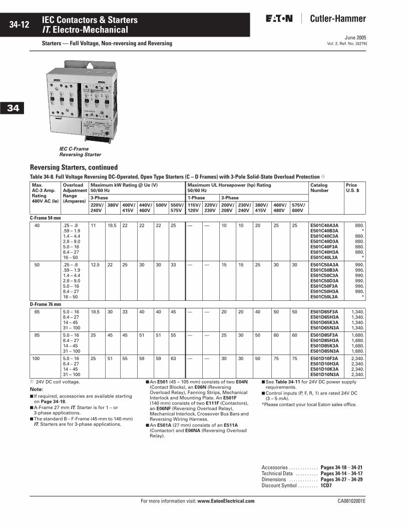
Reversing Starters, continuedTable 34-8. Full Voltage Reversing DC-Operated, Open Type Starters (C – D Frames) with 3-Pole Solid-State Overload Protection �
� 24V DC coil voltage.
Note:
■ If required, accessories are available starting on Page 34-18.
■ A-Frame 27 mm IT. Starter is for 1 – or 3-phase applications.
■ The standard B – F-Frame (45 mm to 140 mm) IT. Starters are for 3-phase applications.
■ An E501 (45 – 105 mm) consists of two E04N (Contact Blocks), an E06N (Reversing Overload Relay), Fanning Strips, Mechanical Interlock and Mounting Plate. An E501F (140 mm) consists of two E111F (Contactors), an E06NF (Reversing Overload Relay), Mechanical Interlock, Crossover Bus Bars and Reversing Wiring Harness.
■ An E501A (27 mm) consists of an E511A (Contactor) and E06NA (Reversing Overload Relay).
■ See Table 34-11 for 24V DC power supply requirements.
■ Control inputs (P, F, R, 1) are rated 24V DC (3 – 5 mA).
*Please contact your local Eaton sales office.
IEC C-Frame Reversing Starter
Max. AC-3 Amp.Rating480V AC (le)
OverloadAdjustmentRange(Amperes)
Maximum kW Rating @ Ue (V)50/60 Hz
Maximum UL Horsepower (hp) Rating 50/60 Hz
CatalogNumber
PriceU.S. $
3-Phase 1-Phase 3-Phase
220V/240V
380V 400V/415V
440V/460V
500V 550V/575V
115V/120V
220V/230V
200V/208V
230V/240V
380V/415V
460V/480V
575V/600V
C-Frame 54 mm40 .25 – .8
.59 – 1.91.4 – 4.42.8 – 9.05.0 – 168.4 – 2716 – 50
11 18.5 22 22 22 25 — — 10 10 20 25 25 E501C40A3AE501C40B3AE501C40C3AE501C40D3AE501C40F3AE501C40H3AE501C40L3A
880.*
880.880.880.880.
*
50 .25 – .8.59 – 1.91.4 – 4.42.8 – 9.05.0 – 168.4 – 2716 – 50
12.5 22 25 30 30 33 — — 15 15 25 30 30 E501C50A3AE501C50B3AE501C50C3AE501C50D3AE501C50F3AE501C50H3AE501C50L3A
990.990.990.990.990.990.
*
D-Frame 76 mm65 5.0 – 16
8.4 – 2714 – 4531 – 100
18.5 30 33 40 40 45 — — 20 20 40 50 50 E501D65F3AE501D65H3AE501D65K3AE501D65N3A
1,340.1,340.1,340.1,340.
85 5.0 – 168.4 – 2714 – 4531 – 100
25 45 45 51 51 55 — — 25 30 50 60 60 E501D85F3AE501D85H3AE501D85K3AE501D85N3A
1,680.1,680.1,680.1,680.
100 5.0 – 168.4 – 2714 – 4531 – 100
25 51 55 59 59 63 — — 30 30 50 75 75 E501D10F3AE501D10H3AE501D10K3AE501D10N3A
2,340.2,340.2,340.2,340.
Accessories . . . . . . . . . . . . . Pages 34-18 – 34-21Technical Data . . . . . . . . . . Pages 34-14 – 34-17Dimensions . . . . . . . . . . . . . Pages 34-27 – 34-29Discount Symbol . . . . . . . . . 1CD7
June 2005
CA08102001E For more information visit: www.EatonElectrical.com
34-13IEC Contactors & Starters
34
IT. Electro-Mechanical Starters — Full Voltage, Non-reversing and ReversingVol. 2, Ref. No. [0277]
Reversing Starters, continuedTable 34-9. Full Voltage Reversing DC-Operated, Open Type Starters (E – F Frames) with 3-Pole Solid-State Overload Protection �
� 24V DC coil voltage.
Note:
■ If required, accessories are available onPage 34-18.
■ A-Frame 27 mm IT. Starter is for 1 – or 3-phase applications.
■ The standard B – F-Frame (45 mm to 140 mm) IT. Starters are for 3-phase applications.
■ An E501 (45 – 105 mm) consists of two E04N (Contact Blocks), an E06N (Reversing Overload Relay), Fanning Strips, Mechanical Interlock and Mounting Plate. An E501F (140 mm) consists of two E111F (Contactors), an E06NF (Reversing Overload Relay), Mechanical Interlock, Crossover Bus Bars and Reversing Wiring Harness.
■ An E501A (27 mm) consists of an E511A (Contactor) and E06NA (Reversing Overload Relay).
■ See Table 34-11 for 24V DC power supply requirements.
■ Control inputs (P, F, R 1) are rated 24V DC (3 – 5 mA).
IEC E-Frame FVR Starter Cat. No. E501E20P3A
IEC F-Frame Reversing Starter
Max. AC-3 Amp.Rating480V AC (le)
OverloadAdjustmentRange(Amperes)
Maximum kW Rating @ Ue (V)50/60 Hz
Maximum UL Horsepower (hp) Rating 50/60 Hz
CatalogNumber
PriceU.S. $
3-Phase 1-Phase 3-Phase
220V/240V
380V 400V/415V
440V/460V
500V 550V/575V
115V/120V
220V/230V
200V/208V
230V/240V
380V/415V
460V/480V
575V/600V
E-Frame 105 mm125 14 – 45
28 – 9042 – 13563 – 200
33 63 63 80 80 80 — — 40 40 60 100 100 E501E12K3AE501E12M3AE501E12P3AE501E12R3A
3,140.3,140.3,140.3,140.
160 14 – 4528 – 9042 – 13563 – 200
45 80 80 100 100 100 — — 50 60 75 125 125 E501E16K3AE501E16M3AE501E16P3AE501E16R3A
4,235.4,235.4,235.4,235.
200 14 – 4528 – 9042 – 13563 – 200
59 100 110 110 110 132 — — 60 75 100 150 150 E501E20K3AE501E20M3AE501E20P3AE501E20R3A
4,475.4,475.4,475.4,475.
F-Frame 140 mm 250 42 – 135
84 – 270131 – 420
75 132 140 160 160 160 — — 75 100 150 200 200 E501F25P3AE501F25S3AE501F25T3A
5,770.5,770.5,770.
315 42 – 13584 – 270
131 – 420
90 160 160 200 200 200 — — 100 125 150 250 250 E501F31P3AE501F31S3AE501F31T3A
8,550.8,550.8,550.
420 42 – 13584 – 270
131 – 420
110 220 220 257 257 257 — — 150 150 200 350 350 E501F42P3AE501F42S3AE501F42T3A
10,830.10,830.10,830.
Accessories . . . . . . . . . . . . . Pages 34-18 – 34-21Technical Data . . . . . . . . . . . Pages 34-14 – 34-17Dimensions . . . . . . . . . . . . . . Pages 34-27 – 34-29Discount Symbol . . . . . . . . . 1CD7
June 2005
34-14
For more information visit: www.EatonElectrical.com CA08102001E
IEC Contactors & Starters
34
IT. Electro-MechanicalTechnical Data and Specifications Vol. 2, Ref. No. [0278]
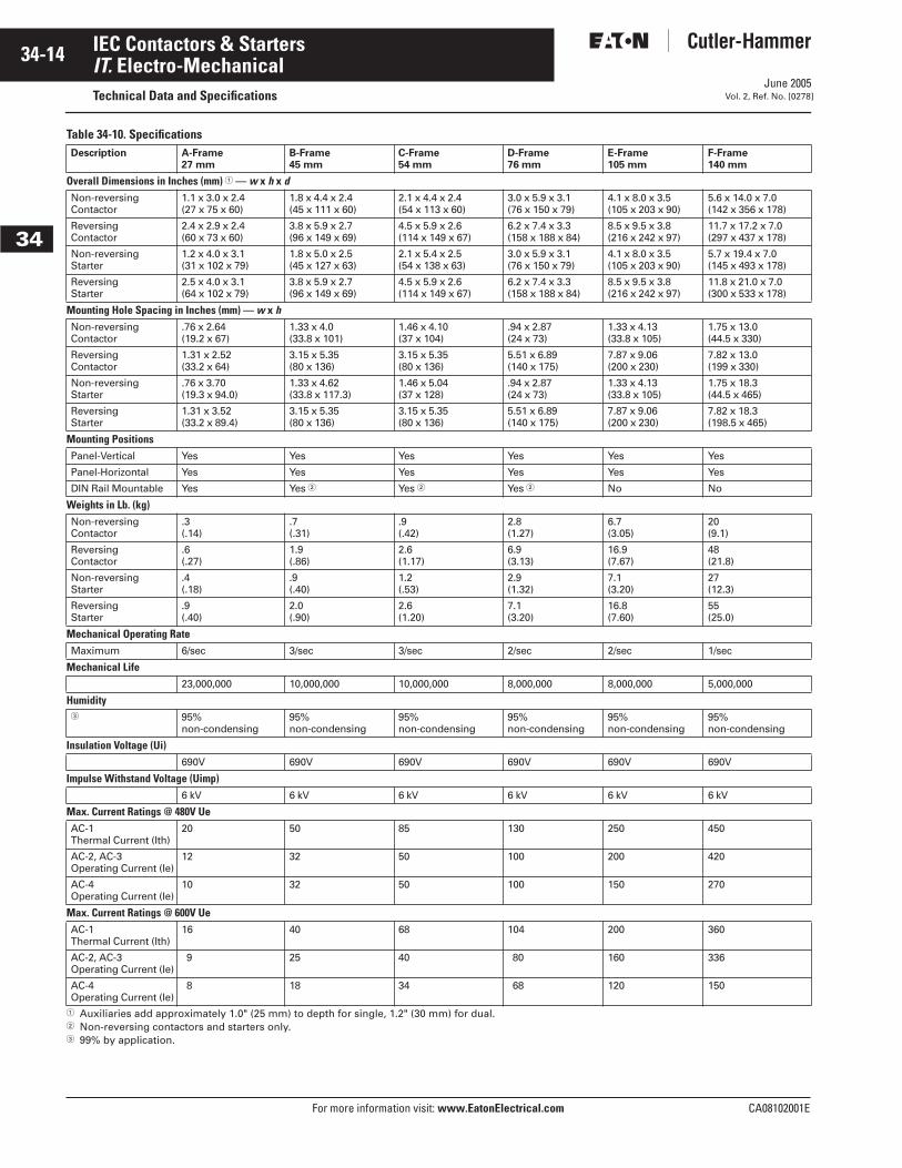
Table 34-10. Specifications
� Auxiliaries add approximately 1.0" (25 mm) to depth for single, 1.2" (30 mm) for dual. � Non-reversing contactors and starters only.� 99% by application.
Description A-Frame27 mm
B-Frame45 mm
C-Frame54 mm
D-Frame76 mm
E-Frame105 mm
F-Frame140 mm
Overall Dimensions in Inches (mm) � — w x h x dNon-reversing Contactor
1.1 x 3.0 x 2.4(27 x 75 x 60)
1.8 x 4.4 x 2.4(45 x 111 x 60)
2.1 x 4.4 x 2.4(54 x 113 x 60)
3.0 x 5.9 x 3.1(76 x 150 x 79)
4.1 x 8.0 x 3.5(105 x 203 x 90)
5.6 x 14.0 x 7.0(142 x 356 x 178)
Reversing Contactor
2.4 x 2.9 x 2.4(60 x 73 x 60)
3.8 x 5.9 x 2.7(96 x 149 x 69)
4.5 x 5.9 x 2.6(114 x 149 x 67)
6.2 x 7.4 x 3.3(158 x 188 x 84)
8.5 x 9.5 x 3.8(216 x 242 x 97)
11.7 x 17.2 x 7.0(297 x 437 x 178)
Non-reversing Starter
1.2 x 4.0 x 3.1(31 x 102 x 79)
1.8 x 5.0 x 2.5(45 x 127 x 63)
2.1 x 5.4 x 2.5(54 x 138 x 63)
3.0 x 5.9 x 3.1(76 x 150 x 79)
4.1 x 8.0 x 3.5(105 x 203 x 90)
5.7 x 19.4 x 7.0(145 x 493 x 178)
Reversing Starter
2.5 x 4.0 x 3.1(64 x 102 x 79)
3.8 x 5.9 x 2.7(96 x 149 x 69)
4.5 x 5.9 x 2.6(114 x 149 x 67)
6.2 x 7.4 x 3.3(158 x 188 x 84)
8.5 x 9.5 x 3.8(216 x 242 x 97)
11.8 x 21.0 x 7.0(300 x 533 x 178)
Mounting Hole Spacing in Inches (mm) — w x h Non-reversing Contactor
.76 x 2.64(19.2 x 67)
1.33 x 4.0 (33.8 x 101)
1.46 x 4.10(37 x 104)
.94 x 2.87 (24 x 73)
1.33 x 4.13 (33.8 x 10⁵)
1.75 x 13.0(44.5 x 330)
Reversing Contactor
1.31 x 2.52 (33.2 x 64)
3.15 x 5.35(80 x 136)
3.15 x 5.35 (80 x 136)
5.51 x 6.89 (140 x 175)
7.87 x 9.06 (200 x 230)
7.82 x 13.0(199 x 330)
Non-reversing Starter
.76 x 3.70(19.3 x 94.0)
1.33 x 4.62 (33.8 x 117.3)
1.46 x 5.04 (37 x 128)
.94 x 2.87 (24 x 73)
1.33 x 4.13 (33.8 x 10⁵)
1.75 x 18.3(44.5 x 465)
Reversing Starter
1.31 x 3.52(33.2 x 89.4)
3.15 x 5.35 (80 x 136)
3.15 x 5.35 (80 x 136)
5.51 x 6.89 (140 x 175)
7.87 x 9.06 (200 x 230)
7.82 x 18.3(198.5 x 465)
Mounting PositionsPanel-Vertical Yes Yes Yes Yes Yes Yes
Panel-Horizontal Yes Yes Yes Yes Yes Yes
DIN Rail Mountable Yes Yes � Yes � Yes � No No
Weights in Lb. (kg)Non-reversing Contactor
.3(.14)
.7(.31)
.9(.42)
2.8(1.27)
6.7(3.05)
20(9.1)
Reversing Contactor
.6(.27)
1.9(.86)
2.6(1.17)
6.9(3.13)
16.9(7.67)
48(21.8)
Non-reversing Starter
.4(.18)
.9(.40)
1.2(.53)
2.9(1.32)
7.1(3.20)
27(12.3)
Reversing Starter
.9(.40)
2.0(.90)
2.6(1.20)
7.1(3.20)
16.8(7.60)
55(25.0)
Mechanical Operating RateMaximum 6/sec 3/sec 3/sec 2/sec 2/sec 1/sec
Mechanical Life23,000,000 10,000,000 10,000,000 8,000,000 8,000,000 5,000,000
Humidity � 95%
non-condensing95%non-condensing
95%non-condensing
95%non-condensing
95%non-condensing
95%non-condensing
Insulation Voltage (Ui)690V 690V 690V 690V 690V 690V
Impulse Withstand Voltage (Uimp)6 kV 6 kV 6 kV 6 kV 6 kV 6 kV
Max. Current Ratings @ 480V Ue AC-1 Thermal Current (Ith)
20 50 85 130 250 450
AC-2, AC-3 Operating Current (Ie)
12 32 50 100 200 420
AC-4 Operating Current (Ie)
10 32 50 100 150 270
Max. Current Ratings @ 600V Ue AC-1 Thermal Current (Ith)
16 40 68 104 200 360
AC-2, AC-3 Operating Current (Ie)
9 25 40 80 160 336
AC-4 Operating Current (Ie)
8 18 34 68 120 150
June 2005
CA08102001E For more information visit: www.EatonElectrical.com
34-15IEC Contactors & Starters
34
IT. Electro-MechanicalTechnical Data and SpecificationsVol. 2, Ref. No. [0279]
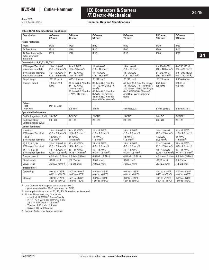
Table 34-10. Specifications (Continued)
� Use Class B 75°C copper wire only (or 90°C copper wire sized for 75°C operation per NEC).
� Not applicable to starter T1, T2, T3. One wire per terminal.� 27 mm Non-reversing Starter —
• (- and +) 14 AWG (1.5 mm2) only• P, F, 1, A: 1 wire per terminal only,
22 – 14 AWG (0.5 – 1.5 mm2) • Torque: 2.25 lb-in (.25 Nm)• Driver: .09 in (2.5 mm)
� Consult factory for higher ratings.
Description A-Frame27 mm
B-Frame45 mm
C-Frame54 mm
D-Frame76 mm
E-Frame105 mm
F-Frame140 mm
Finger ProtectionFront IP20 IP20 IP20 IP20 IP20 IP20
At Terminals IP20 IP10 IP10 IP00 IP00 IP00
At Terminals with max. size wire installed
IP20 IP20 IP10 IP10 IP00 IP00
Terminals L1, L2, L3/T1, T2, T3 �
1 Wire per Terminal(stranded or solid)
16 – 12 AWG(1.5 – 2.5 mm2)
14 – 8 AWG(1.5 – 10 mm2)
14 – 4 AWG(1.5 – 16 mm2)
14 – 1 AWG(1.5 – 35 mm2)
6 – 250 MCM(16 – 120 mm2)
4 – 750 MCM(25 – 420 mm2)
2 Wires per Terminal(stranded or solid)
16 – 12 AWG �(1.5 – 2.5 mm2)
14 – 10 AWG(1.5 – 4 mm2)
14 – 6 AWG(1.5 – 16 mm2)
14 – 2 AWG(1.5 – 25 mm2)
6 – 3/0 AWG(16 – 70 mm2)
1/0 – 300 MCM(50 – 150 mm2)
Strip Length .32" (8 mm) .45" (11 mm) .5" (12 mm) .7" (18 mm) .8" (21 mm) 1.5" (40 mm)
Torque (max.) 18 lb-in (2.0 Nm)
20 lb-in (2.2 Nm) for 14 – 10 AWG (1.5 – 6 mm2);25 lb-in (2.8 Nm) for 8 AWG (10 mm2)
35 lb-in (4.0 Nm) for 14 – 10 AWG (1.5 – 6 mm2);40 lb-in (4.5 Nm) for 8 AWG (10 mm2);45 lb-in (5.0 Nm) for 6 – 4 AWG (16 mm2)
45 lb-in (5.0 Nm) for Single 14 – 8 AWG (1.5 – 10 mm2); 100 lb-in (11 Nm) for Single 6 – 1 AWG (16 – 35 mm2) and Dual Wire Combina-tions
250 lb-in (28 Nm)
550 lb-in(62 Nm)
DriverFlatHex Key
PZ1 or 3/16"—
—2.5 mm
—3 mm
—4 mm [5/32"]
—8 mm [5/16"]
—8 mm [5/16"]
Operation PerformanceCoil Voltage (nominal) 24V DC 24V DC 24V DC 24V DC 24V DC 24V DC
Coil Operating Voltage Range (VDC)
20 – 28 20 – 28 20 – 28 20 – 28 20 – 28 20 – 28
Control Terminals(- and +)1 Wire per Terminal
14 – 12 AWG �(1.5 – 2.5 mm2)
14 – 12 AWG(1.5 – 2.5 mm2)
14 – 12 AWG(1.5 – 2.5 mm2)
14 – 12 AWG(1.5 – 2.5 mm2)
14 – 12 AWG(1.5 – 2.5 mm2)
14 – 12 AWG(1.5 – 2.5 mm2)
(- and +)2 Wires per Terminal
14 AWG �(1.5 mm2)
14 AWG(1.5 mm2)
14 AWG(1.5 mm2)
14 AWG(1.5 mm2)
14 AWG(1.5 mm2)
14 AWG(1.5 mm2)
(P, F, R, 1, 2, 3)1 Wire per Terminal
22 – 12 AWG �(0.5 – 2.5 mm2)
22 – 12 AWG(0.5 – 2.5 mm2)
22 – 12 AWG(0.5 – 2.5 mm2)
22 – 12 AWG(0.5 – 2.5 mm2)
22 – 12 AWG(0.5 – 2.5 mm2)
22 – 12 AWG(0.5 – 2.5 mm2)
(P, F, R, 1, 2, 3)2 Wires per Terminal
18 – 14 AWG �(0.75 – 1.5 mm2)
18 – 14 AWG(0.75 – 1.5 mm2)
18 – 14 AWG(0.75 – 1.5 mm2)
18 – 14 AWG(0.75 – 1.5 mm2)
18 – 14 AWG(0.75 – 1.5 mm2)
18 – 14 AWG(0.75 – 1.5 mm2)
Torque (max.) 4.5 lb-in (.5 Nm) 4.5 lb-in (.5 Nm) 4.5 lb-in (.5 Nm) 4.5 lb-in (.5 Nm) 4.5 lb-in (.5 Nm) 4.5 lb-in (.5 Nm)
Strip Length .25 (7 mm) .25 (7 mm) .25 (7 mm) .25 (7 mm) .25 (7 mm) .25 (7 mm)
Driver (Flat) .13 (3.5 mm) � .13 (3.5 mm) .13 (3.5 mm) .13 (3.5 mm) .13 (3.5 mm) .13 (3.5 mm)
Temperature �
Operating -40° to +149°F(-40° to +65°C)
-40° to +149°F(-40° to +65°C)
-40° to +149°F(-40° to +65°C)
-40° to +149°F(-40° to +65°C)
-40° to +149°F(-40° to +65°C)
-40° to +149°F(-40° to +65°C)
Storage -58° to +176°F(-50° to +80°C)
-58° to +176°F(-50° to +80°C)
-58° to +176°F(-50° to +80°C)
-58° to +176°F(-50° to +80°C)
-58° to +176°F(-50° to +80°C)
-58° to +176°F(-50° to +80°C)
June 2005
34-16
For more information visit: www.EatonElectrical.com CA08102001E
IEC Contactors & Starters
34
IT. Electro-MechanicalTechnical Data and Specifications Vol. 2, Ref. No. [0280]
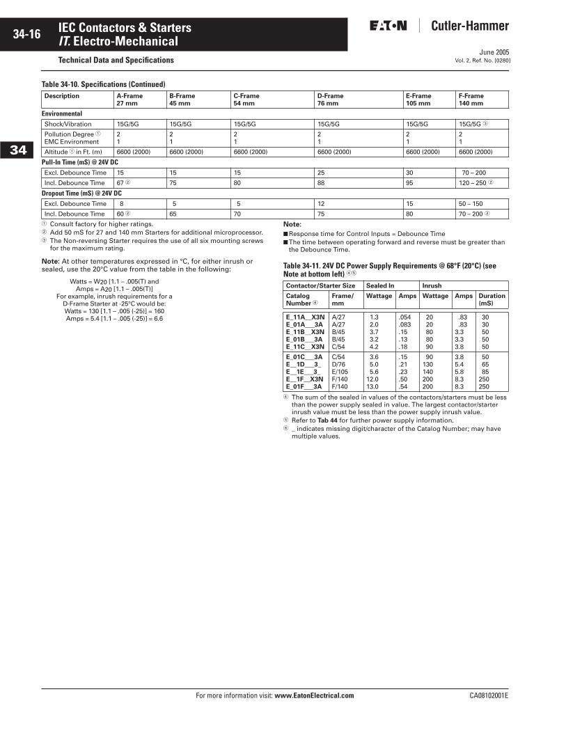
Table 34-10. Specifications (Continued)
� Consult factory for higher ratings.� Add 50 mS for 27 and 140 mm Starters for additional microprocessor.� The Non-reversing Starter requires the use of all six mounting screws
for the maximum rating.
Note: At other temperatures expressed in °C, for either inrush or sealed, use the 20°C value from the table in the following:
Note:
■ Response time for Control Inputs = Debounce Time■ The time between operating forward and reverse must be greater than
the Debounce Time.
Table 34-11. 24V DC Power Supply Requirements @ 68°F (20°C) (see Note at bottom left) ��
� The sum of the sealed in values of the contactors/starters must be less than the power supply sealed in value. The largest contactor/starter inrush value must be less than the power supply inrush value.
� Refer to Tab 44 for further power supply information.� _ indicates missing digit/character of the Catalog Number; may have
multiple values.
Description A-Frame27 mm
B-Frame45 mm
C-Frame54 mm
D-Frame76 mm
E-Frame105 mm
F-Frame140 mm
EnvironmentalShock/Vibration 15G/5G 15G/5G 15G/5G 15G/5G 15G/5G 15G/5G �
Pollution Degree �EMC Environment
21
21
21
21
21
21
Altitude � in Ft. (m) 6600 (2000) 6600 (2000) 6600 (2000) 6600 (2000) 6600 (2000) 6600 (2000)
Pull-In Time (mS) @ 24V DCExcl. Debounce Time 15 15 15 25 30 70 – 200
Incl. Debounce Time 67 � 75 80 88 95 120 – 250 �
Dropout Time (mS) @ 24V DCExcl. Debounce Time 8 5 5 12 15 50 – 150
Incl. Debounce Time 60 � 65 70 75 80 70 – 200 �
Watts = W20 [1.1 – .005(T) andAmps = A20 [1.1 – .005(T)]
For example, inrush requirements for a D-Frame Starter at -25°C would be:Watts = 130 [1.1 – .005 (-25)] = 160Amps = 5.4 [1.1 – .005 (-25)] = 6.6
Contactor/Starter Size Sealed In Inrush
CatalogNumber �
Frame/mm
Wattage Amps Wattage Amps Duration(mS)
E_11A__X3NE_01A___3AE_11B__X3NE_01B___3AE_11C__X3N
A/27A/27B/45B/45C/54
1.32.03.73.24.2
.054
.083
.15
.13
.18
2020808090
.83
.833.33.33.8
3030505050
E_01C___3AE__1D___3_E__1E___3_E__1F__X3NE_01F___3A
C/54D/76E/105F/140F/140
3.65.05.6
12.013.0
.15
.21
.23
.50
.54
90130140200200
3.85.45.88.38.3
506585
250250

CA08102001E For more information visit: www.EatonElectrical.com
34-17IEC Contactors & Starters
June 2005
34
IT. Electro-MechanicalTechnical Data and SpecificationsVol. 2, Ref. No. [0281]
Electrical Life — AC-1, AC-2, AC-3 and AC-4 Utilization CategoriesTable 34-12. Utilization Categories
Life Load Curves — Eaton’s Cutler-Hammer IT. Electro-Mechanical Series IEC contactors have been designed and manufactured for superior life performance. All testing has been based on requirements as found in IEC 60947-4-1 and conducted by us. When selecting a contactor designed to IEC requirements, the specifier must give attention to the specific load, utiliza-tion category and the required electri-cal life. For a definition of Utilization Categories, see Table 34-12 above.
Note: AC-3 tests are conducted at rated device currents and AC-4 tests are con-ducted at six-times rated device currents. All tests have been run at 460V, 60 Hz.
Actual application life may vary, depending on environmental condi-tions and application duty cycle.
Figure 34-1. Electrical Life — AC-3 Utilization Category
Figure 34-2. Electrical Life — AC-4 Utilization Category
The International Electrotechnical Commission (IEC) has developed utilization categories for contactors and auxiliary contacts. The categories describe the type of electrical load and the conditions for making and breaking the current.
Category Typical Application
AC-1 Non-inductive or slightly inductive loads: Resistance furnaces, heating.
AC-2 Slip-ring motors: Starting and stopping of running motors
AC-3 Squirrel cage motors: Starting, switching off motors during running (motors in most industrial applications typically fall into this cate-gory).
AC-4 Squirrel cage motors: Starting, plugging �, inching � (very few applications in industry are totally AC-4).� Plugging is stopping or reversing the motor rapidly by reversing the connections while the motor is running.� Inching or jogging is energizing the motor once or repeatedly for short durations to obtain small movements of the motor driven load.
1 6 910 25 40 65 100 160 250
1812 32 50 85 125 200 315420
Operational Current
A B C D E FFrame Size
10,000,000
1,000,000
100,000
10,000
Ope
ratio
ns
Note: Preliminary data.
0.1 1 6 910 25 40 65 100 148
18 32 50 85 125 250320
Operational Current
A B C D E FFrame Size
10,000,000
1,000,000
100,000
10,000
Ope
ratio
ns
Note: Preliminary data.
Trip Times
Figure 34-3. Class 10, 20 and 30 Trip Curves
Contactor Choice —■ Decide what utilization category the
application is and choose the appropriate curve from Figure 34-1 or Figure 34-2.
■ Locate the intersection of the life-load curve with the operational cur-rent (le) of the application, as found on the horizontal axis.
■ Read the estimated contact life along the vertical axis in number of operations.
1000.0
100.0
10.0
1.0
0.11 2 3 4 5 6 7 8 9
2
416
35
10
Trip
Tim
e (S
eco
nd
s)
Trip Class 10 ColdTrip Class 10 HotTrip Class 20 ColdTrip Class 20 HotTrip Class 30 ColdTrip Class 30 Hot
123456
Multiples of FLA
June 2005
34-18
For more information visit: www.EatonElectrical.com CA08102001E
IEC Contactors & Starters
34
IT. Electro-MechanicalAccessories Vol. 2, Ref. No. [0282]
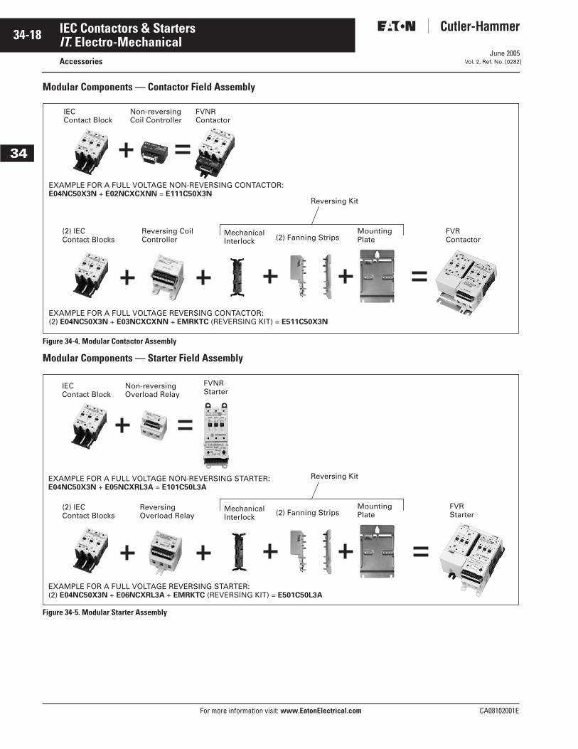
Modular Components — Contactor Field Assembly
Figure 34-4. Modular Contactor Assembly
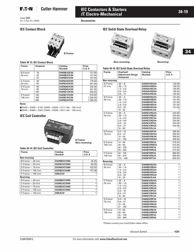
Modular Components — Starter Field Assembly
Figure 34-5. Modular Starter Assembly
IEC Contact Block
Non-reversingCoil Controller
FVNRContactor
EXAMPLE FOR A FULL VOLTAGE REVERSING CONTACTOR:(2) E04NC50X3N + E03NCXCXNN + EMRKTC (REVERSING KIT) = E511C50X3N
FVRContactor
Reversing Coil Controller
Mechanical Interlock (2) Fanning Strips
(2) IECContact Blocks
Mounting Plate
EXAMPLE FOR A FULL VOLTAGE NON-REVERSING CONTACTOR:E04NC50X3N + E02NCXCXNN = E111C50X3N
Reversing Kit
Non-reversing Overload Relay
FVNRStarter
FVRStarter
Reversing Overload Relay
EXAMPLE FOR A FULL VOLTAGE NON-REVERSING STARTER:E04NC50X3N + E05NCXRL3A = E101C50L3A
EXAMPLE FOR A FULL VOLTAGE REVERSING STARTER:(2) E04NC50X3N + E06NCXRL3A + EMRKTC (REVERSING KIT) = E501C50L3A
IEC Contact Block
Mechanical Interlock (2) Fanning Strips
(2) IECContact Blocks
Mounting Plate
Reversing Kit
June 2005
CA08102001E For more information visit: www.EatonElectrical.com
34-19IEC Contactors & Starters
34
IT. Electro-MechanicalAccessoriesVol. 2, Ref. No. [0283]
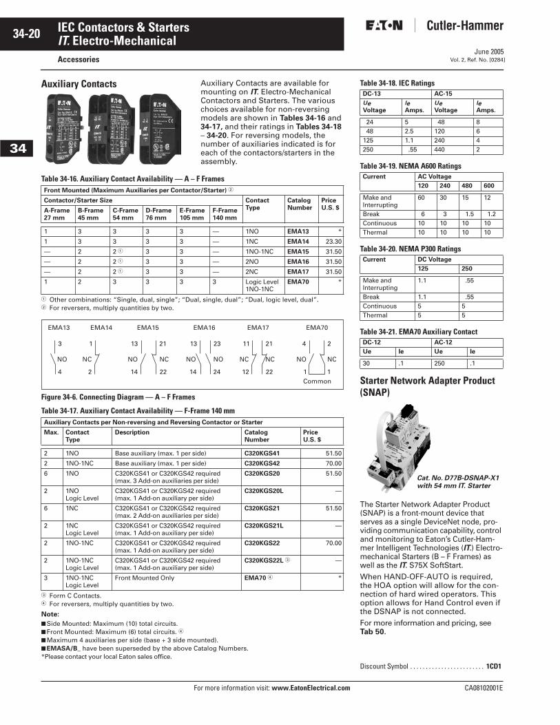
IEC Contact Block
Table 34-13. IEC Contact Block
Note:
■ E04N + E05N = E101; E04N + E02N = E111 (45 – 105 mm)■ E04N + E06N = E501; E04N + E03N = E511 (45 – 105 mm)
IEC Coil Controller
Table 34-14. IEC Coil Controller
IEC Solid-State Overload Relay
Table 34-15. IEC Solid-State Overload Relay
*Please contact your local Eaton sales office.
Frame Amperes CatalogNumber
PriceU.S. $
B-Frame45 mm
182532
E04NB18X3NE04NB25X3NE04NB32X3N
121.00141.00167.00
C-Frame54 mm
4050
E04NC40X3NE04NC50X3N
179.00201.00
D-Frame76 mm
6585
100
E04ND65X3NE04ND85X3NE04ND10X3N
292.00341.00545.00
E-Frame105 mm
125160200
E04NE12X3NE04NE16X3NE04NE20X3N
875.001,290.001,460.00
Frame CatalogNumber
Price U.S. $
Non-reversingB-Frame — 45 mm E02NBXCXNN 45.25C-Frame — 54 mm E02NCXCXNN 68.50D-Frame — 76 mm E02NDXCXNN 102.00E-Frame — 105 mm E02NEXCXNN 137.00F-Frame — 140 mm EMUCCF *
ReversingB-Frame — 45 mm E03NBXCXNN *C-Frame — 54 mm E03NCXCXNN *D-Frame — 76 mm E03NDXCXNN *E-Frame — 105 mm E03NEXCXNN *F-Frame — 140 mm EMUCCF *
B Frame
B FrameNon-reversing
Frame Overload Adjustment Range (Amperes)
CatalogNumber
PriceU.S. $
Non-reversingA-Frame27 mm
.25 – .8
.59 – 1.91.4 – 4.42.8 – 9.03.8 – 12
E05NAXRA3AE05NAXRB3AE05NAXRC3AE05NAXRD3AE05NAXRE3A
130.00130.00130.00130.00130.00
B-Frame45 mm
.25 – .8
.59 – 1.91.4 – 4.42.8 – 9.06.3 – 2010 – 32
E05NBXRA3AE05NBXRB3AE05NBXRC3AE05NBXRD3AE05NBXRG3AE05NBXRJ3A
131.00131.00131.00131.00131.00
*C-Frame54 mm
.25 – .8
.59 – 1.91.4 – 4.42.8 – 9.05.0 – 168.4 – 2716 – 50
E05NCXRA3AE05NCXRB3AE05NCXRC3AE05NCXRD3AE05NCXRF3AE05NCXRH3AE05NCXRL3A
234.00234.00234.00234.00234.00234.00
*D-Frame76 mm
5.0 – 168.4 – 2714 – 4531 – 100
E05NDXRF3AE05NDXRH3AE05NDXRK3AE05NDXRN3A
309.00309.00309.00309.00
E-Frame105 mm
14 – 4528 – 9042 – 13563 – 200
E05NEXRK3AE05NEXRM3AE05NEXRP3AE05NEXRR3A
515.00515.00515.00515.00
F-Frame140 mm
42 – 13584 – 270131 – 420
E05NFXRP3AE05NFXRS3AE05NFXRT3A
890.00890.00890.00
ReversingB-Frame45 mm
.25 – .8
.59 – 1.91.4 – 4.42.8 – 9.06.3 – 2010 – 32
E06NBXRA3AE06NBXRB3AE06NBXRC3AE06NBXRD3AE06NBXRG3AE06NBXRJ3A
******
C-Frame54 mm
.25 – .8
.59 – 1.91.4 – 4.42.8 – 9.05.0 – 168.4 – 2716 – 50
E06NCXRA3AE06NCXRB3AE06NCXRC3AE06NCXRD3AE06NCXRF3AE06NCXRH3AE06NCXRL3A
*******
D-Frame76 mm
5.0 – 168.4 – 2714 – 4531 – 100
E06NDXRF3AE06NDXRH3AE06NDXRK3AE06NDXRN3A
****
E-Frame105 mm
14 – 4528 – 9042 – 13563 – 200
E06NEXRK3AE06NEXRM3AE06NEXRP3AE06NEXRR3A
****
Discount Symbol . . . . . . . . . . . . . . . . . . . . . . . . 1CD1
Non-reversing Reversing
June 2005
34-20
For more information visit: www.EatonElectrical.com CA08102001E
IEC Contactors & Starters
34
IT. Electro-MechanicalAccessories Vol. 2, Ref. No. [0284]
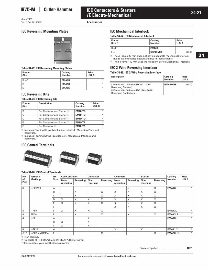
Auxiliary Contacts Auxiliary Contacts are available for mounting on IT. Electro-Mechanical Contactors and Starters. The various choices available for non-reversing models are shown in Tables 34-16 and 34-17, and their ratings in Tables 34-18 – 34-20. For reversing models, the number of auxiliaries indicated is for each of the contactors/starters in the assembly.
Table 34-16. Auxiliary Contact Availability — A – F Frames
� Other combinations: “Single, dual, single”; “Dual, single, dual”; “Dual, logic level, dual”.� For reversers, multiply quantities by two.
Figure 34-6. Connecting Diagram — A – F Frames
Table 34-17. Auxiliary Contact Availability — F-Frame 140 mm
� Form C Contacts.� For reversers, multiply quantities by two.
Note:
■ Side Mounted: Maximum (10) total circuits.■ Front Mounted: Maximum (6) total circuits. �
■ Maximum 4 auxiliaries per side (base + 3 side mounted).■ EMASA/B_ have been superseded by the above Catalog Numbers.*Please contact your local Eaton sales office.
Front Mounted (Maximum Auxiliaries per Contactor/Starter) �
Contactor/Starter Size ContactType
Catalog Number
PriceU.S. $A-Frame
27 mmB-Frame45 mm
C-Frame54 mm
D-Frame76 mm
E-Frame105 mm
F-Frame140 mm
1 3 3 3 3 — 1NO EMA13 *
1 3 3 3 3 — 1NC EMA14 23.30
— 2 2 � 3 3 — 1NO-1NC EMA15 31.50
— 2 2 � 3 3 — 2NO EMA16 31.50
— 2 2 � 3 3 — 2NC EMA17 31.50
1 2 3 3 3 3 Logic Level1NO-1NC
EMA70 *
Auxiliary Contacts per Non-reversing and Reversing Contactor or Starter
Max. ContactType
Description Catalog Number
PriceU.S. $
2 1NO Base auxiliary (max. 1 per side) C320KGS41 51.50
2 1NO-1NC Base auxiliary (max. 1 per side) C320KGS42 70.00
6 1NO C320KGS41 or C320KGS42 required(max. 3 Add-on auxiliaries per side)
C320KGS20 51.50
2 1NOLogic Level
C320KGS41 or C320KGS42 required(max. 1 Add-on auxiliary per side)
C320KGS20L —
6 1NC C320KGS41 or C320KGS42 required (max. 2 Add-on auxiliaries per side)
C320KGS21 51.50
2 1NCLogic Level
C320KGS41 or C320KGS42 required(max. 1 Add-on auxiliary per side)
C320KGS21L —
2 1NO-1NC C320KGS41 or C320KGS42 required (max. 1 Add-on auxiliary per side)
C320KGS22 70.00
2 1NO-1NC Logic Level
C320KGS41 or C320KGS42 required(max. 1 Add-on auxiliary per side)
C320KGS22L � —
3 1NO-1NC Logic Level
Front Mounted Only EMA70 � *
1
NC
2
EMA14
4
NO
1
23 21
NC
22
EMA70
13
NO
14
11
NC
12
13
NO
14
EMA15 EMA16 EMA17
3
EMA13
NO
4
2
NC
1
21
NC
22
NO
24Common
Table 34-18. IEC Ratings
Table 34-19. NEMA A600 Ratings
Table 34-20. NEMA P300 Ratings
Table 34-21. EMA70 Auxiliary Contact
Starter Network Adapter Product (SNAP)
The Starter Network Adapter Product (SNAP) is a front-mount device that serves as a single DeviceNet node, pro-viding communication capability, control and monitoring to Eaton’s Cutler-Ham-mer Intelligent Technologies (IT.) Electro-mechanical Starters (B – F Frames) as well as the IT. S75X SoftStart.When HAND-OFF-AUTO is required, the HOA option will allow for the con-nection of hard wired operators. This option allows for Hand Control even if the DSNAP is not connected. For more information and pricing, see Tab 50.
DC-13 AC-15
Ue Voltage
le Amps.
Ue Voltage
le Amps.
24 5 48 848 2.5 120 6
125 1.1 240 4250 .55 440 2
Current AC Voltage
120 240 480 600
Make and Interrupting
60 30 15 12
Break 6 3 1.5 1.2Continuous 10 10 10 10Thermal 10 10 10 10
Current DC Voltage
125 250
Make and Interrupting
1.1 .55
Break 1.1 .55Continuous 5 5Thermal 5 5
DC-12 AC-12
Ue Ie Ue Ie
30 .1 250 .1
Discount Symbol . . . . . . . . . . . . . . . . . . . . . . . . 1CD1
Cat. No. D77B-DSNAP-X1 with 54 mm IT. Starter
June 2005
CA08102001E For more information visit: www.EatonElectrical.com
34-21IEC Contactors & Starters
34
IT. Electro-MechanicalAccessoriesVol. 2, Ref. No. [0285]
IEC Reversing Mounting Plates
Table 34-22. IEC Reversing Mounting Plates
IEC Reversing KitsTable 34-23. IEC Reversing Kits
� Includes Fanning Strips, Mechanical Interlock, Mounting Plate and hardware.
� Includes Fanning Strips (Bus Bar Set), Mechanical Interlock and hardware.
IEC Mechanical InterlockTable 34-24. IEC Mechanical Interlock
� The A-Frame 27 mm does not have a separate mechanical interlock due to its embedded design and board requirements.
� The F-Frame 140 mm uses the Freedom Series Mechanical Interlock.
IEC 2-Wire Reversing InterfaceTable 34-25. IEC 2-Wire Reversing Interface
IEC Control Terminals
Table 34-26. IEC Control Terminals
� Non-locking.� Consists of (1) EMA77L and (1) EMA77LR inter-wired.*Please contact your local Eaton sales office.
FrameSize
CatalogNumber
PriceU.S. $
B – C EMA9B *
D EMA9D *
E EMA9E *
FrameSize
Description CatalogNumber
PriceU.S. $
B For Contactor and Starter � EMRKTB *
C For Contactor and Starter � EMRKTC *
D For Contactor and Starter � EMRKTD *
E For Contactor and Starter � EMRKTE *
F For Contactor � EMRKTF *
FrameSize �
CatalogNumber
PriceU.S. $
B – E EMMB *
F � C321KM50 65.00
Description CatalogNumber
PriceU.S. $
8-Pin for 45 – 140 mm (IEC 6A – 420AReversing Starters)8-Pin for 45 – 105 mm (IEC 18A – 200AReversing Contactors)
EMA2WR8 104.00
No. of Pins
Terminal Markings
IEC Size
Coil Controller Contactor Overload Starter CatalogNumber
PriceU.S. $Non-
reversing Reversing Non-
reversing Reversing Non-
reversing Reversing Non-
reversing Reversing
8 -+PFR123 A X X EMA76L *
B X X X X X X
C X X X X X X
D X X X X X X X X
E X X X X X X X X
F X X X X
5 -+PFR F X X X X EMA77L *
5 RFP+- F X X X X EMA77LR *
4 -+PF A X EMA78L *
B X X
C X X
6 -+PF1A A X X EMA81 � *
(2) 5 -+PFR and RFP+- F X X EMA80L � *
Discount Symbol . . . . . . . . . . . . . . . . . . . . . . . . 1CD1
June 2005
34-22
For more information visit: www.EatonElectrical.com CA08102001E
IEC Contactors & Starters
34
IT. Electro-MechanicalRenewal Parts Vol. 2, Ref. No. [0286]
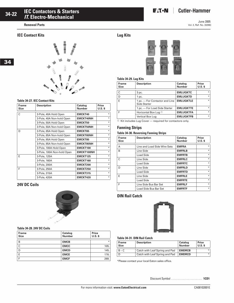
IEC Contact Kits
Table 34-27. IEC Contact Kits
24V DC Coils
Table 34-28. 24V DC Coils
Lug Kits
Table 34-29. Lug Kits
� Kit includes Lug Cover — required for contactors only.
Fanning StripsTable 34-30. Reversing Fanning Strips
DIN Rail Catch
Table 34-31. DIN Rail Catch
*Please contact your local Eaton sales office.
FrameSize
Description CatalogNumber
PriceU.S. $
C 3-Pole, 40A Hold Open EMCKT40 *
3-Pole, 40A Non-hold Open EMCKT40NH *
3-Pole, 50A Hold Open EMCKT50 *
3-Pole, 50A Non-hold Open EMCKT50NH *
D 3-Pole, 65A Hold Open EMCKT65 *
3-Pole, 65A Non-hold Open EMCKT65NH *
3-Pole, 85A Hold Open EMCKT85 *
3-Pole, 85A Non-hold Open EMCKT85NH *
3-Pole, 100A Hold Open EMCKT100 *
3-Pole, 100A Non-hold Open EMCKT100NH *
E 3-Pole, 125A EMCKT125 *
3-Pole, 160A EMCKT160 *
3-Pole, 200A EMCKT200 *
F 3-Pole, 250A EMCKT250 *
3-Pole, 315A EMCKT315 *
3-Pole, 420A EMCKT420 *
FrameSize
CatalogNumber
PriceU.S. $
B EMCB *
C EMCC 105.
D EMCD 145.
E EMCE 178.
F EMCF 289.
FrameSize
Description CatalogNumber
PriceU.S. $
C 3 pc. EMLUGKTC *
D 1 pc. EMLUGKTD *
E 1 pc. — For Contactor and Line Side Starter
EMLUGKTLE *
1 pc. — For Load Side Starter EMLUGKTTE *
F Horizontal Box Lug � EMLUGKTFA *
Vertical Box Lug EMLUGKTFB *
FrameSize
Description CatalogNumber
PriceU.S. $
A Line and Load Side Wire Sets EMFRA *
B Line Side EMFRLB *
Load Side EMFRTB *
C Line Side EMFRLC *
Load Side EMFRTC *
D Line Side EMFRLD *
Load Side EMFRTD *
E Line Side EMFRLE *
Load Side EMFRTE *
F Line Side Bus Bar Set EMFRLF *
Load Side Bus Bar Set EMFRTF *
FrameSize
Description CatalogNumber
PriceU.S. $
B – C Catch with Leaf Spring and Pad EMDRCB *D Catch with Leaf Spring and Pad EMDRCD *
Discount Symbol . . . . . . . . . . . . . . . . . . . . . . . . 1CD1
June 2005
CA08102001E For more information visit: www.EatonElectrical.com
34-23IEC Contactors & Starters
34
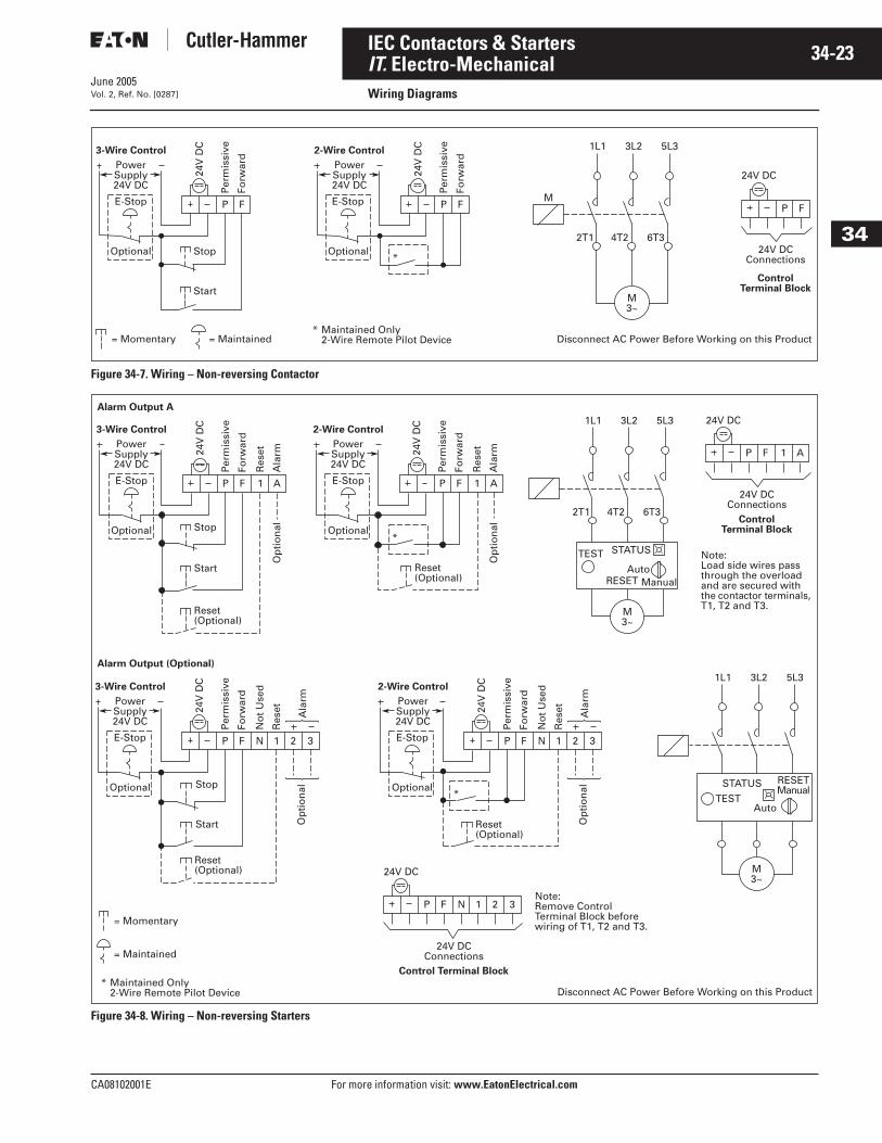
IT. Electro-MechanicalWiring DiagramsVol. 2, Ref. No. [0287]
Figure 34-7. Wiring – Non-reversing Contactor
Figure 34-8. Wiring – Non-reversing Starters
ControlTerminal Block
PowerSupply24V DC
24V
DC
Per
mis
sive
Forw
ard
E-Stop P F
Optional
= Momentary = Maintained
E-Stop
OptionalStop
Start
PowerSupply24V DC
24V
DC
Per
mis
sive
Forw
ard
P
*
* Maintained Only 2-Wire Remote Pilot Device Disconnect AC Power Before Working on this Product
1L1 3L2 5L3
2T1 4T2
M
6T3
F
24V DC
24V DCConnections
3-Wire Control 2-Wire Control
P F
M3~
24V
DC
Per
mis
sive
Forw
ard
Stop
Start
Reset(Optional)
Stop
Start
Reset(Optional)
Reset(Optional)
E-Stop
Optional
E-Stop
Optional
E-Stop
Optional
P F
Res
et
Ala
rmO
pti
on
al
Op
tio
nal
Op
tio
nal
1 A
24V
DC
Per
mis
sive
Forw
ard
P F
No
t U
sed
N
Res
et Ala
rm
1 2 3
24V
DC
Per
mis
sive
Forw
ard
Alarm Output A
E-Stop
Optional
P FR
eset
Ala
rm1 A
P F 1 A
*
* Maintained Only 2-Wire Remote Pilot Device
= Momentary
= Maintained
Disconnect AC Power Before Working on this Product
*
1L1
Alarm Output (Optional)
3L2 5L3
1L1 3L2 5L3
2T1 4T2 6T3
24V DC
24V DC
ControlTerminal Block
PowerSupply24V DC
3-Wire Control
PowerSupply24V DC
2-Wire Control
PowerSupply24V DC
3-Wire Control
PowerSupply24V DC
2-Wire Control
24V DCConnections
Control Terminal Block
24V DCConnections
TEST STATUS
RESET ManualAuto
TEST
STATUS RESETManual
Auto
24V
DC
Per
mis
sive
Forw
ard
P F
No
t U
sed
N
Res
et Ala
rm
1 2 3
P F N 1 2 3
Op
tio
nal
M3~
M3~
Reset(Optional)
Note:Load side wires pass through the overload and are secured with the contactor terminals, T1, T2 and T3.
Note:Remove Control Terminal Block before wiring of T1, T2 and T3.

June 2005
34-24
For more information visit: www.EatonElectrical.com CA08102001E
IEC Contactors & Starters
34
IT. Electro-MechanicalDimensions Vol. 2, Ref. No. [0288]
Non-reversing and Reversing Contactors (Frame A)Table 34-32. Approximate Dimensions in Inches (mm)
Figure 34-9. Approximate Dimensions — Inches (mm)
Non-reversing Contactors (Frames B & C)Table 34-33. Approximate Dimensions in Inches (mm)
Figure 34-10. Approximate Dimensions — Inches (mm)
FrameSize
Overall Mounting Holes Req. Mtg.Screws
Terminals
Width Height Depth Depth w/Auxiliary
Depth addedw/DIN Rail
Width Height Mtg. Holeto Top
DIN Railto Top
Control Line Load
A B C D E F G H J K P Q R
Non-reversingA 1.1
(27)3.0(75)
2.4(60)
3.5(88)
.2(5)
.76(19.2)
2.64(67)
.1(3.5)
.6(15)
(3) #8M4
.6(16)
1.7(43)
1.7(43)
ReversingA 2.4
(60)2.9(73)
2.4(60)
3.5(88)
.2(5)
1.31(33.2)
2.52(64)
.2(5)
.5(13)
(3) #8M4
.6(16)
1.7(43)
1.7(43)
FrameSize
Overall Mounting Holes Req. Mtg.Screws
Terminals
Width Height Depth Depth w/Auxiliary
Depth addedw/DIN Rail
Width Height Mtg. Holeto Top
DIN Railto Top
Control Line Load
A B C D E F G H J K P Q R
B 1.8(45)
4.4(111)
2.4(60)
3.6(91)
.1(3)
1.33(33.8)
4.0(101)
.2(5)
.9(23)
(3) #8M4
.7(19)
1.2(30)
1.2(30)
C 2.1(54)
4.45(113)
2.4(60)
3.6(91)
.1(3)
1.46(37)
4.1(104)
.2(5)
.8(20)
(3) #8M4
.7(19)
1.2(30)
1.2(30)
ControlTerminal
Block
K
H
G
JLogic Level Auxiliary –
Reduce Dim “D”.28 (7) for the
Single Auxiliaries B
FA
GB
F
A
RP
E
QC
D
Line Terminals(1 L1, 3 L2, 5 L3)
Load Terminals(2 T1, 4 T2, 6 T3)
Non-reversingContactors
ReversingContactors
StandardDIN Rail1.38 x .3(35 x 7.5)(OptionalMounting)
K
J
RP Control
Terminal BlockE
Load Terminals(2 T1, 4 T2, 6 T3)
Dual Auxiliary –Reduce Dim “D”
.31 (8) for theSingle Auxiliaries
K
QC FH
G
J
B
AD
Line Terminals(1 L1, 3 L2, 5 L3)
StandardDIN Rail1.38 x .3(35 x 7.5)
(Optional Mounting)
C-Frame Pictured(B-Frame Has Two Lower Mtg. Feet,
Reference F – Width)
June 2005
CA08102001E For more information visit: www.EatonElectrical.com
34-25IEC Contactors & Starters
34
IT. Electro-MechanicalDimensionsVol. 2, Ref. No. [0289]
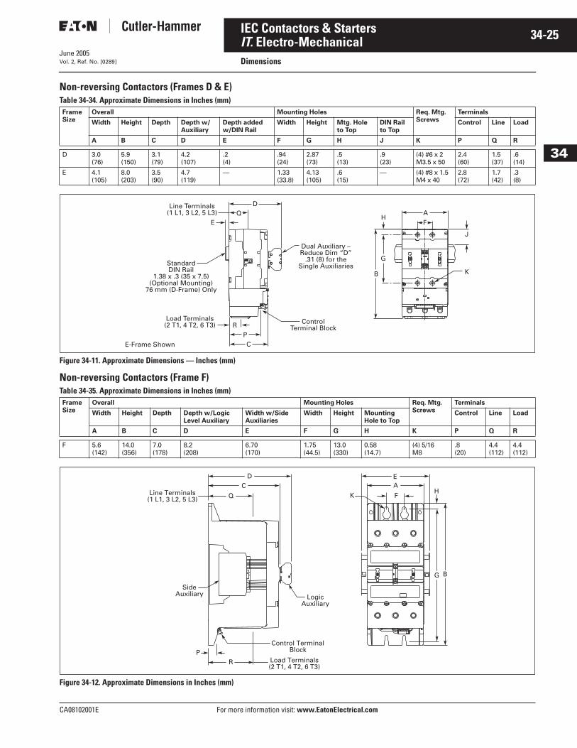
Non-reversing Contactors (Frames D & E) Table 34-34. Approximate Dimensions in Inches (mm)
Figure 34-11. Approximate Dimensions — Inches (mm)
Non-reversing Contactors (Frame F)Table 34-35. Approximate Dimensions in Inches (mm)
Figure 34-12. Approximate Dimensions in Inches (mm)
FrameSize
Overall Mounting Holes Req. Mtg.Screws
Terminals
Width Height Depth Depth w/Auxiliary
Depth addedw/DIN Rail
Width Height Mtg. Holeto Top
DIN Railto Top
Control Line Load
A B C D E F G H J K P Q R
D 3.0(76)
5.9(150)
3.1(79)
4.2(107)
.2(4)
.94(24)
2.87(73)
.5(13)
.9(23)
(4) #6 x 2M3.5 x 50
2.4(60)
1.5(37)
.6(14)
E 4.1(105)
8.0(203)
3.5(90)
4.7(119)
— 1.33(33.8)
4.13(105)
.6(15)
— (4) #8 x 1.5M4 x 40
2.8(72)
1.7(42)
.3(8)
FrameSize
Overall Mounting Holes Req. Mtg.Screws
Terminals
Width Height Depth Depth w/LogicLevel Auxiliary
Width w/SideAuxiliaries
Width Height MountingHole to Top
Control Line Load
A B C D E F G H K P Q R
F 5.6(142)
14.0(356)
7.0(178)
8.2(208)
6.70(170)
1.75(44.5)
13.0(330)
0.58(14.7)
(4) 5/16M8
.8(20)
4.4(112)
4.4(112)
2 T1 T24 T36
K
J
H
G
B
Dual Auxiliary –Reduce Dim “D”
.31 (8) for theSingle Auxiliaries
AF
QE
DLine Terminals(1 L1, 3 L2, 5 L3)
StandardDIN Rail
1.38 x .3 (35 x 7.5)(Optional Mounting)
76 mm (D-Frame) Only
ControlTerminal BlockR
P
Load Terminals(2 T1, 4 T2, 6 T3)
E-Frame Shown C
Load Terminals (2 T1, 4 T2, 6 T3)
PR
Line Terminals (1 L1, 3 L2, 5 L3)
DC
Q
EA
FK
Logic Auxiliary
Side Auxiliary
Control Terminal Block
G B
H
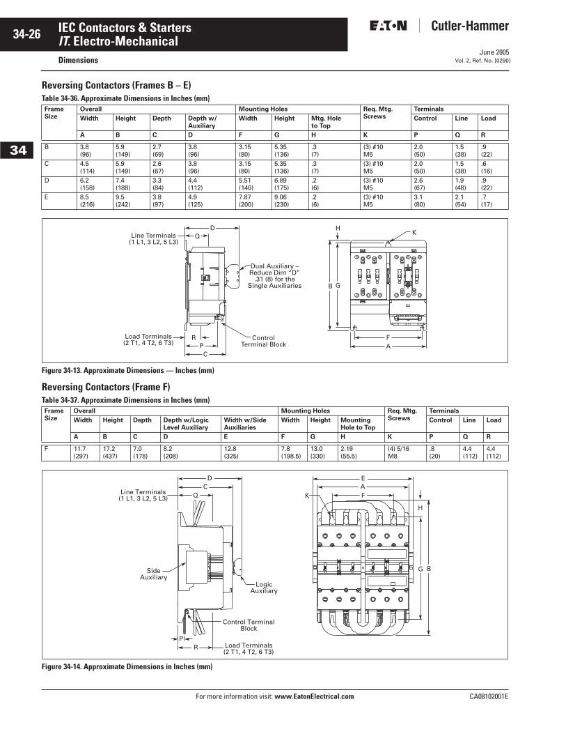
June 2005
34-26
For more information visit: www.EatonElectrical.com CA08102001E
IEC Contactors & Starters
34
IT. Electro-MechanicalDimensions Vol. 2, Ref. No. [0290]
Reversing Contactors (Frames B – E) Table 34-36. Approximate Dimensions in Inches (mm)
Figure 34-13. Approximate Dimensions — Inches (mm)
Reversing Contactors (Frame F)Table 34-37. Approximate Dimensions in Inches (mm)
Figure 34-14. Approximate Dimensions in Inches (mm)
FrameSize
Overall Mounting Holes Req. Mtg.Screws
Terminals
Width Height Depth Depth w/Auxiliary
Width Height Mtg. Holeto Top
Control Line Load
A B C D F G H K P Q R
B 3.8(96)
5.9(149)
2.7(69)
3.8(96)
3.15(80)
5.35(136)
.3(7)
(3) #10M5
2.0(50)
1.5(38)
.9(22)
C 4.5(114)
5.9(149)
2.6(67)
3.8(96)
3.15(80)
5.35(136)
.3(7)
(3) #10M5
2.0(50)
1.5(38)
.6(16)
D 6.2(158)
7.4(188)
3.3(84)
4.4(112)
5.51(140)
6.89(175)
.2(6)
(3) #10M5
2.6(67)
1.9(48)
.9(22)
E 8.5(216)
9.5(242)
3.8(97)
4.9(125)
7.87(200)
9.06(230)
.2(6)
(3) #10M5
3.1(80)
2.1(54)
.7(17)
FrameSize
Overall Mounting Holes Req. Mtg.Screws
Terminals
Width Height Depth Depth w/LogicLevel Auxiliary
Width w/SideAuxiliaries
Width Height MountingHole to Top
Control Line Load
A B C D E F G H K P Q R
F 11.7(297)
17.2(437)
7.0(178)
8.2(208)
12.8(325)
7.8(198.5)
13.0(330)
2.19(55.5)
(4) 5/16M8
.8(20)
4.4(112)
4.4(112)
ControlTerminal Block
Dual Auxiliary –Reduce Dim “D”
.31 (8) for theSingle Auxiliaries
K
PFRA
C
H
GB
QD
Line Terminals(1 L1, 3 L2, 5 L3)
Load Terminals(2 T1, 4 T2, 6 T3)
Logic Auxiliary
Side Auxiliary
Control Terminal Block
Load Terminals (2 T1, 4 T2, 6 T3)
PR
Q
DC
F
EA
Line Terminals (1 L1, 3 L2, 5 L3) K
G B
H
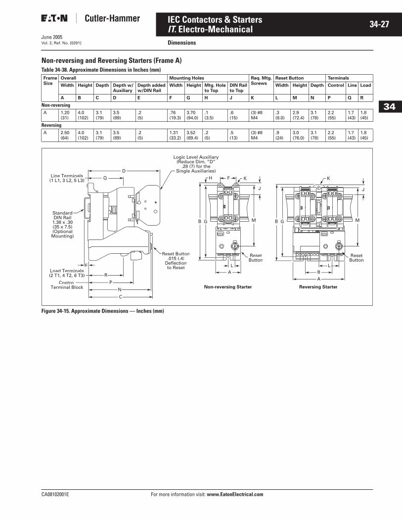
June 2005
CA08102001E For more information visit: www.EatonElectrical.com
34-27IEC Contactors & Starters
34
IT. Electro-MechanicalDimensionsVol. 2, Ref. No. [0291]
Non-reversing and Reversing Starters (Frame A)Table 34-38. Approximate Dimensions in Inches (mm)
Figure 34-15. Approximate Dimensions — Inches (mm)
FrameSize
Overall Mounting Holes Req. Mtg.Screws
Reset Button Terminals
Width Height Depth Depth w/Auxiliary
Depth addedw/DIN Rail
Width Height Mtg. Holeto Top
DIN Railto Top
Width Height Depth Control Line Load
A B C D E F G H J K L M N P Q R
Non-reversingA 1.20
(31)4.0(102)
3.1(79)
3.5(89)
.2(5)
.76(19.3)
3.70(94.0)
.1(3.5)
.6(15)
(3) #8M4
.3(8.0)
2.9(72.4)
3.1(78)
2.2(55)
1.7(43)
1.8(45)
ReversingA 2.50
(64)4.0(102)
3.1(79)
3.5(89)
.2(5)
1.31(33.2)
3.52(89.4)
.2(5)
.5(13)
(3) #8M4
.9(24)
3.0(76.0)
3.1(78)
2.2(55)
1.7(43)
1.8(45)
Load Terminals(2 T1, 4 T2, 6 T3)
ControlTerminal Block Non-reversing Starter Reversing Starter
LA
Line Terminals(1 L1, 3 L2, 5 L3)
D
Logic Level Auxiliary(Reduce Dim. ”D”
.28 (7) for theSingle Auxiliaries)
Q FH
E
R
P
N
C
K K
LBA
M
J
B G B G
Reset Button.015 (.4)
Deflectionto Reset
StandardDIN Rail
1.38 x .30(35 x 7.5)(OptionalMounting)
ResetButton
M
J
ResetButton
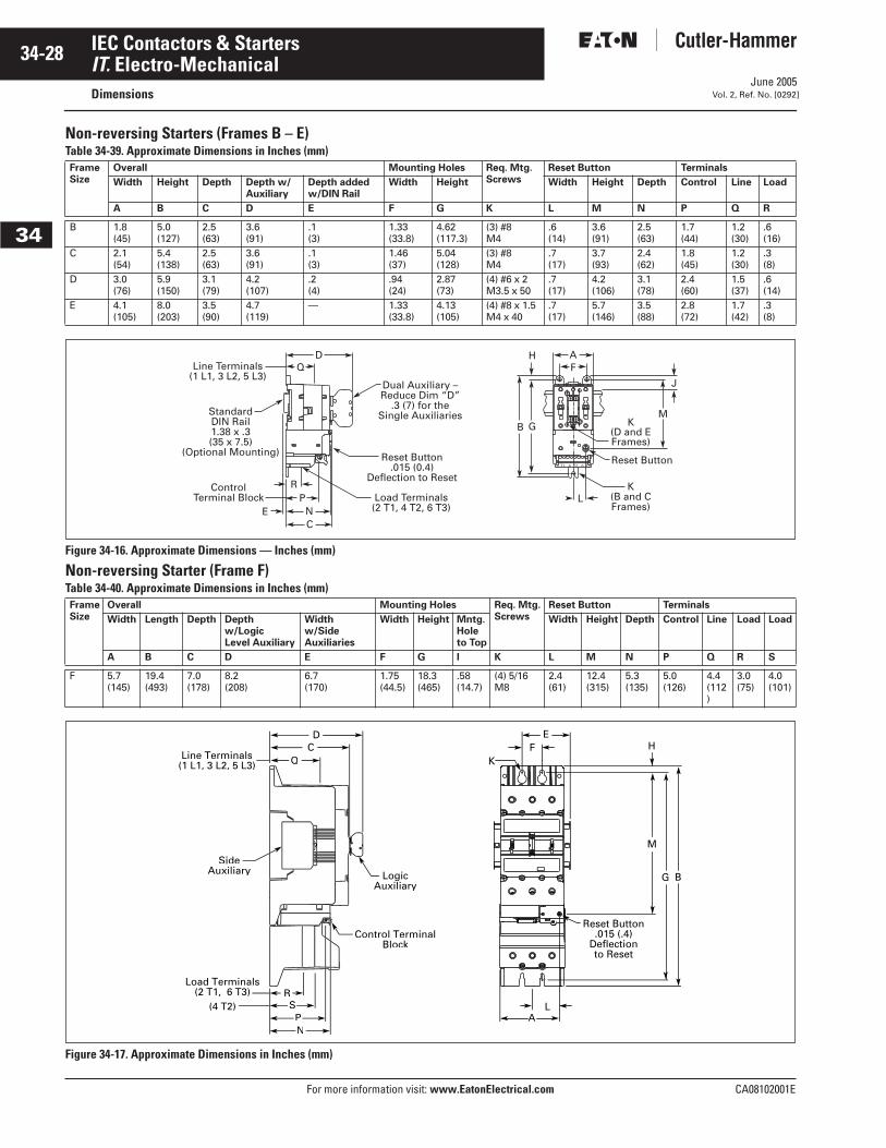
June 2005
34-28
For more information visit: www.EatonElectrical.com CA08102001E
IEC Contactors & Starters
34
IT. Electro-MechanicalDimensions Vol. 2, Ref. No. [0292]
Non-reversing Starters (Frames B – E) Table 34-39. Approximate Dimensions in Inches (mm)
Figure 34-16. Approximate Dimensions — Inches (mm)
Non-reversing Starter (Frame F)Table 34-40. Approximate Dimensions in Inches (mm)
Figure 34-17. Approximate Dimensions in Inches (mm)
FrameSize
Overall Mounting Holes Req. Mtg.Screws
Reset Button Terminals
Width Height Depth Depth w/Auxiliary
Depth addedw/DIN Rail
Width Height Width Height Depth Control Line Load
A B C D E F G K L M N P Q R
B 1.8(45)
5.0(127)
2.5(63)
3.6(91)
.1(3)
1.33(33.8)
4.62(117.3)
(3) #8M4
.6(14)
3.6(91)
2.5(63)
1.7(44)
1.2(30)
.6(16)
C 2.1(54)
5.4(138)
2.5(63)
3.6(91)
.1(3)
1.46(37)
5.04(128)
(3) #8M4
.7(17)
3.7(93)
2.4(62)
1.8(45)
1.2(30)
.3(8)
D 3.0(76)
5.9(150)
3.1(79)
4.2(107)
.2(4)
.94(24)
2.87(73)
(4) #6 x 2M3.5 x 50
.7(17)
4.2(106)
3.1(78)
2.4(60)
1.5(37)
.6(14)
E 4.1(105)
8.0(203)
3.5(90)
4.7(119)
— 1.33(33.8)
4.13(105)
(4) #8 x 1.5M4 x 40
.7(17)
5.7(146)
3.5(88)
2.8(72)
1.7(42)
.3(8)
FrameSize
Overall Mounting Holes Req. Mtg.Screws
Reset Button Terminals
Width Length Depth Depth w/LogicLevel Auxiliary
Width w/SideAuxiliaries
Width Height Mntg.Holeto Top
Width Height Depth Control Line Load Load
A B C D E F G I K L M N P Q R S
F 5.7(145)
19.4(493)
7.0(178)
8.2(208)
6.7(170)
1.75(44.5)
18.3(465)
.58(14.7)
(4) 5/16 M8
2.4(61)
12.4(315)
5.3(135)
5.0(126)
4.4(112)
3.0(75)
4.0(101)
L
Reset Button.015 (0.4)
Deflection to Reset
Load Terminals(2 T1, 4 T2, 6 T3)
Reset Button
K(B and CFrames)
K(D and EFrames)
Q
ControlTerminal Block P
R
E NC
Dual Auxiliary –Reduce Dim “D”
.3 (7) for theSingle Auxiliaries
J
M
H
GB
FAD
Line Terminals(1 L1, 3 L2, 5 L3)
StandardDIN Rail1.38 x .3(35 x 7.5)
(Optional Mounting)
SideAuxiliary Logic
Auxiliary
Control TerminalBlock
SPN
Load Terminals(2 T1, 6 T3)
(4 T2)R
AL
Q
DC
Line Terminals(1 L1, 3 L2, 5 L3)
FE
K
G B
M
H
Reset Button.015 (.4)
Deflectionto Reset
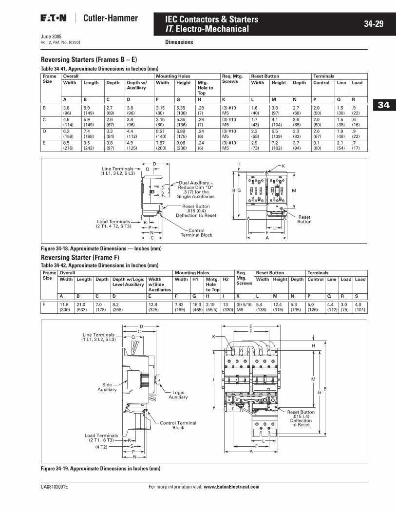
June 2005
CA08102001E For more information visit: www.EatonElectrical.com
34-29IEC Contactors & Starters
34
IT. Electro-MechanicalDimensionsVol. 2, Ref. No. [0293]
Reversing Starters (Frames B – E) Table 34-41. Approximate Dimensions in Inches (mm)
Figure 34-18. Approximate Dimensions — Inches (mm)
Reversing Starter (Frame F)Table 34-42. Approximate Dimensions in Inches (mm)
Figure 34-19. Approximate Dimensions in Inches (mm)
FrameSize
Overall Mounting Holes Req. Mtg.Screws
Reset Button Terminals
Width Length Depth Depth w/Auxiliary
Width Height Mtg. Hole to Top
Width Height Depth Control Line Load
A B C D F G H K L M N P Q R
B 3.8(96)
5.9(149)
2.7(69)
3.8(96)
3.15(80)
5.35(136)
.28(7)
(3) #10M5
1.6(40)
3.8(97)
2.7(68)
2.0(50)
1.5(38)
.9(22)
C 4.5(114)
5.9(149)
2.6(67)
3.8(96)
3.15(80)
5.35(136)
.28(7)
(3) #10M5
1.7(43)
4.1(104)
2.6(65)
2.0(50)
1.5(38)
.6(16)
D 6.2(158)
7.4(188)
3.3(84)
4.4(112)
5.51(140)
6.89(175)
.24(6)
(3) #10M5
2.3(58)
5.5(139)
3.3(83)
2.6(67)
1.9(48)
.9(22)
E 8.5(216)
9.5(242)
3.8(97)
4.9(125)
7.87(200)
9.06(230)
.24(6)
(3) #10M5
2.9(73)
7.2(182)
3.7(94)
3.1(80)
2.1(54)
.7(17)
FrameSize
Overall Mounting Holes Req.Mtg.Screws
Reset Button Terminals
Width Length Depth Depth w/LogicLevel Auxiliary
Width w/SideAuxiliaries
Width H1 Mntg.Holeto Top
H2 Width Height Depth Control Line Load Load
A B C D E F G H I K L M N P Q R S
F 11.8(300)
21.0(533)
7.0(178)
8.2(208)
12.8(325)
7.82(199)
18.3(465)
2.19(55.5)
13(330)
(5) 5/16M8
5.4(138)
12.4(315)
5.3(135)
5.0(126)
4.4(112)
3.0(75)
4.0(101)
ResetButton
K
PF
RL
NAC
G M
ControlTerminal Block
Reset Button.015 (0.4)
Deflection to Reset
Dual Auxiliary –Reduce Dim “D”
.3 (7) for theSingle Auxiliaries
B
QD H
Line Terminals(1 L1, 3 L2, 5 L3)
Load Terminals(2 T1, 4 T2, 6 T3)
Side Auxiliary
Logic Auxiliary
Control Terminal Block
SPN
Load Terminals (2 T1, 6 T3)
(4 T2)R
FA
L
Q
DC
EF
Line Terminals (1 L1, 3 L2, 5 L3) K
GB
I M
H
Reset Button.015 (.4)
Deflectionto Reset
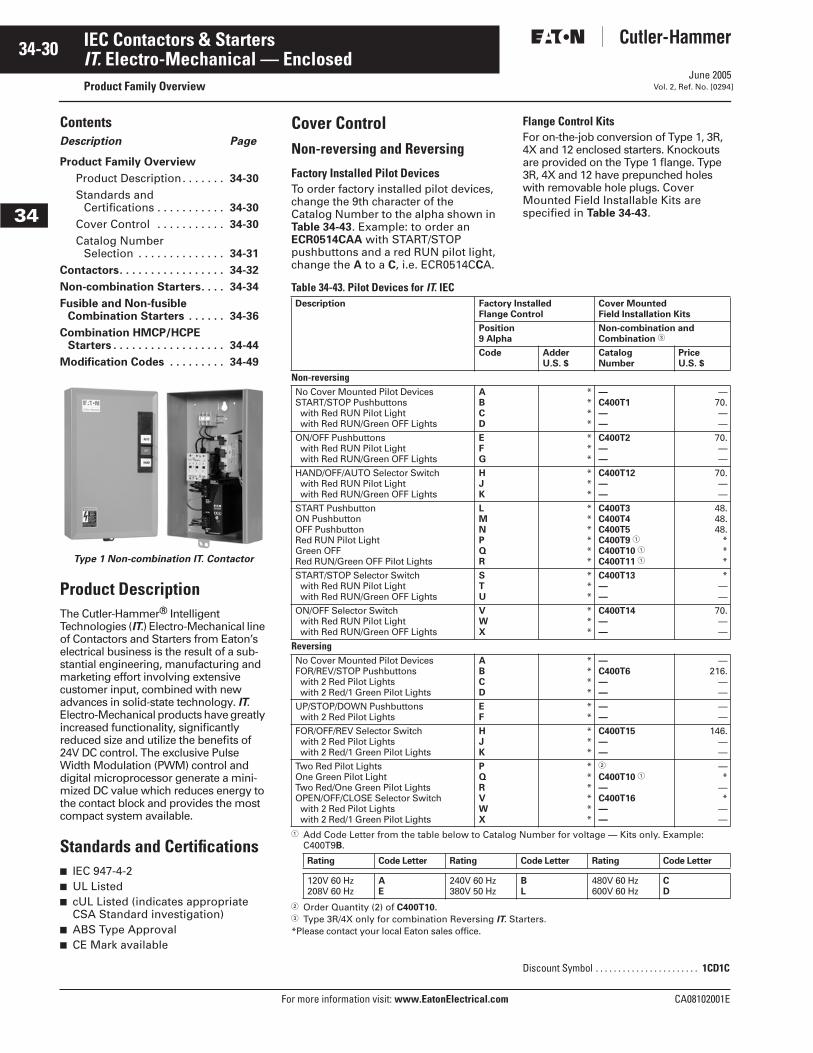
June 2005
34-30
For more information visit: www.EatonElectrical.com CA08102001E
IEC Contactors & Starters
34
IT. Electro-Mechanical — EnclosedProduct Family Overview Vol. 2, Ref. No. [0294]
ContentsDescription Page
Product Family Overview
Product Description. . . . . . . 34-30
Standards and Certifications . . . . . . . . . . . 34-30
Cover Control . . . . . . . . . . . 34-30
Catalog Number Selection . . . . . . . . . . . . . . 34-31
Contactors. . . . . . . . . . . . . . . . . 34-32
Non-combination Starters. . . . 34-34
Fusible and Non-fusibleCombination Starters . . . . . . 34-36
Combination HMCP/HCPEStarters . . . . . . . . . . . . . . . . . . 34-44
Modification Codes . . . . . . . . . 34-49
Product DescriptionThe Cutler-Hammer® Intelligent Technologies (IT.) Electro-Mechanical line of Contactors and Starters from Eaton’s electrical business is the result of a sub-stantial engineering, manufacturing and marketing effort involving extensive customer input, combined with new advances in solid-state technology. IT. Electro-Mechanical products have greatly increased functionality, significantly reduced size and utilize the benefits of 24V DC control. The exclusive Pulse Width Modulation (PWM) control and digital microprocessor generate a mini-mized DC value which reduces energy to the contact block and provides the most compact system available.
Standards and Certifications■ IEC 947-4-2■ UL Listed■ cUL Listed (indicates appropriate
CSA Standard investigation)■ ABS Type Approval■ CE Mark available
Type 1 Non-combination IT. Contactor
Cover ControlNon-reversing and Reversing
Factory Installed Pilot DevicesTo order factory installed pilot devices, change the 9th character of the Catalog Number to the alpha shown in Table 34-43. Example: to order an ECR0514CAA with START/STOP pushbuttons and a red RUN pilot light, change the A to a C, i.e. ECR0514CCA.
Flange Control KitsFor on-the-job conversion of Type 1, 3R, 4X and 12 enclosed starters. Knockouts are provided on the Type 1 flange. Type 3R, 4X and 12 have prepunched holes with removable hole plugs. Cover Mounted Field Installable Kits are specified in Table 34-43.
Table 34-43. Pilot Devices for IT. IEC
� Add Code Letter from the table below to Catalog Number for voltage — Kits only. Example: C400T9B.
� Order Quantity (2) of C400T10.� Type 3R/4X only for combination Reversing IT. Starters.*Please contact your local Eaton sales office.
Description Factory InstalledFlange Control
Cover Mounted Field Installation Kits
Position9 Alpha
Non-combination and Combination �
Code AdderU.S. $
CatalogNumber
PriceU.S. $
Non-reversingNo Cover Mounted Pilot DevicesSTART/STOP Pushbuttonswith Red RUN Pilot Lightwith Red RUN/Green OFF Lights
ABCD
****
—C400T1——
—70.——
ON/OFF Pushbuttonswith Red RUN Pilot Lightwith Red RUN/Green OFF Lights
EFG
***
C400T2——
70.——
HAND/OFF/AUTO Selector Switchwith Red RUN Pilot Lightwith Red RUN/Green OFF Lights
HJK
***
C400T12——
70.——
START PushbuttonON PushbuttonOFF PushbuttonRed RUN Pilot LightGreen OFFRed RUN/Green OFF Pilot Lights
LMNPQR
******
C400T3C400T4C400T5C400T9 �
C400T10 �
C400T11 �
48.48.48.
***
START/STOP Selector Switchwith Red RUN Pilot Lightwith Red RUN/Green OFF Lights
STU
***
C400T13——
*——
ON/OFF Selector Switchwith Red RUN Pilot Lightwith Red RUN/Green OFF Lights
VWX
***
C400T14——
70.——
ReversingNo Cover Mounted Pilot DevicesFOR/REV/STOP Pushbuttonswith 2 Red Pilot Lightswith 2 Red/1 Green Pilot Lights
ABCD
****
—C400T6——
—216.
——
UP/STOP/DOWN Pushbuttonswith 2 Red Pilot Lights
EF
**
——
——
FOR/OFF/REV Selector Switchwith 2 Red Pilot Lightswith 2 Red/1 Green Pilot Lights
HJK
***
C400T15——
146.——
Two Red Pilot LightsOne Green Pilot LightTwo Red/One Green Pilot LightsOPEN/OFF/CLOSE Selector Switchwith 2 Red Pilot Lightswith 2 Red/1 Green Pilot Lights
PQRVWX
******
�
C400T10 �
—C400T16——
—*
—*
——
Rating Code Letter Rating Code Letter Rating Code Letter
120V 60 Hz208V 60 Hz
AE
240V 60 Hz380V 50 Hz
BL
480V 60 Hz600V 60 Hz
CD
Discount Symbol . . . . . . . . . . . . . . . . . . . . . . . 1CD1C
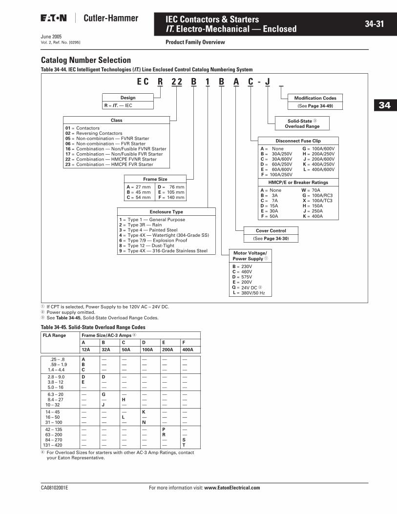
June 2005
CA08102001E For more information visit: www.EatonElectrical.com
34-31IEC Contactors & Starters
34
IT. Electro-Mechanical — EnclosedProduct Family OverviewVol. 2, Ref. No. [0295]
Catalog Number SelectionTable 34-44. IEC Intelligent Technologies (IT.) Line Enclosed Control Catalog Numbering System
� If CPT is selected, Power Supply to be 120V AC – 24V DC.� Power supply omitted.� See Table 34-45, Solid-State Overload Range Codes.
Table 34-45. Solid-State Overload Range Codes
� For Overload Sizes for starters with other AC-3 Amp Ratings, contact your Eaton Representative.
FLA Range Frame Size/AC-3 Amps �
A B C D E F
12A 32A 50A 100A 200A 400A
.25 – .8
.59 – 1.91.4 – 4.4
ABC
———
———
———
———
———
2.8 – 9.03.8 – 125.0 – 16
DE—
D——
———
———
———
———
6.3 – 208.4 – 27
10 – 32
———
G—J
—H—
———
———
———
14 – 4516 – 5031 – 100
———
———
—L—
K—N
———
———
42 – 13563 – 20084 – 270
131 – 420
————
————
————
————
PR——
——ST
E C R 2 2 B 1 B A C - J
Design
R = IT. — IEC
Disconnect Fuse Clip
A =B =C =D =E =F =
None30A/250V30A/600V60A/250V60A/600V
100A/250V
G =H =J =K =L =
100A/600V200A/250V200A/600V400A/250V400A/600V
HMCP/E or Breaker Ratings
A =B =C =D =E =F =
None3A7A
15A30A50A
W =G =X =H =J =K =
70A100A/RC3100A/TC3150A250A400A
Cover Control
(See Page 34-30)
Modification Codes
(See Page 34-49)
Solid-State �
Overload Range
Class
01 =02 =05 =06 =16 =17 =22 =23 =
ContactorsReversing ContactorsNon-combination — FVNR StarterNon-combination — FVR StarterCombination — Non/Fusible FVNR StarterCombination — Non/Fusible FVR StarterCombination — HMCPE FVNR StarterCombination — HMCPE FVR Starter
Frame Size
A =B =C =
27 mm45 mm54 mm
D =E =F =
76 mm105 mm140 mm
Enclosure Type
1 =2 =3 =4 =6 =8 =9 =
Type 1 — General PurposeType 3R — RainType 4 — Painted SteelType 4X — Watertight (304-Grade SS)Type 7/9 — Explosion ProofType 12 — Dust-TightType 4X — 316-Grade Stainless Steel
Motor Voltage/
Power Supply �
B =C =D =E =Q =L =
230V460V575V200V24V DC �380V/50 Hz
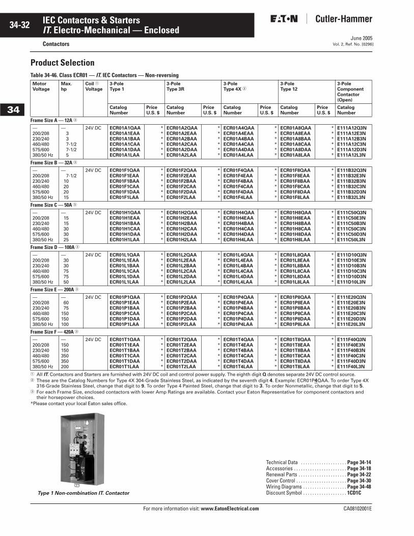
June 2005
34-32
For more information visit: www.EatonElectrical.com CA08102001E
IEC Contactors & Starters
34
IT. Electro-Mechanical — EnclosedContactors Vol. 2, Ref. No. [0296]
Product SelectionTable 34-46. Class ECR01 — IT. IEC Contactors — Non-reversing
� All IT. Contactors and Starters are furnished with 24V DC coil and control power supply. The eighth digit Q denotes separate 24V DC control source.� These are the Catalog Numbers for Type 4X 304-Grade Stainless Steel, as indicated by the seventh digit 4. Example: ECR01P4QAA. To order Type 4X
316-Grade Stainless Steel, change that digit to 9. To order Type 4 Painted Steel, change that digit to 3. To order Nonmetallic, change that digit to 5.� For each Frame Size, enclosed contactors with lower Amp Ratings are available. Contact your Eaton Representative for component contactors and
their horsepower choices.*Please contact your local Eaton sales office.
Type 1 Non-combination IT. Contactor
MotorVoltage
Max.hp
Coil �
Voltage3-PoleType 1
3-PoleType 3R
3-PoleType 4X �
3-PoleType 12
3-Pole ComponentContactor (Open)
CatalogNumber
PriceU.S. $
CatalogNumber
PriceU.S. $
CatalogNumber
PriceU.S. $
CatalogNumber
PriceU.S. $
CatalogNumber
Frame Size A — 12A �
—200/208230/240460/480575/600380/50 Hz
—337-1/27-1/25
24V DC ECR01A1QAAECR01A1EAAECR01A1BAAECR01A1CAAECR01A1DAAECR01A1LAA
******
ECR01A2QAAECR01A2EAAECR01A2BAAECR01A2CAAECR01A2DAAECR01A2LAA
******
ECR01A4QAAECR01A4EAAECR01A4BAAECR01A4CAAECR01A4DAAECR01A4LAA
******
ECR01A8QAAECR01A8EAAECR01A8BAAECR01A8CAAECR01A8DAAECR01A8LAA
******
E111A12Q3NE111A12E3NE111A12B3NE111A12C3NE111A12D3NE111A12L3N
Frame Size B — 32A �
—200/208230/240460/480575/600380/50 Hz
—7-1/2
10202015
24V DC ECR01F1QAAECR01F1EAAECR01F1BAAECR01F1CAAECR01F1DAAECR01F1LAA
******
ECR01F2QAAECR01F2EAAECR01F2BAAECR01F2CAAECR01F2DAAECR01F2LAA
******
ECR01F4QAAECR01F4EAAECR01F4BAAECR01F4CAAECR01F4DAAECR01F4LAA
******
ECR01F8QAAECR01F8EAAECR01F8BAAECR01F8CAAECR01F8DAAECR01F8LAA
******
E111B32Q3NE111B32E3NE111B32B3NE111B32C3NE111B32D3NE111B32L3N
Frame Size C — 50A �
—200/208230/240460/480575/600380/50 Hz
—1515303025
24V DC ECR01H1QAAECR01H1EAAECR01H1BAAECR01H1CAAECR01H1DAAECR01H1LAA
******
ECR01H2QAAECR01H2EAAECR01H2BAAECR01H2CAAECR01H2DAAECR01H2LAA
******
ECR01H4QAAECR01H4EAAECR01H4BAAECR01H4CAAECR01H4DAAECR01H4LAA
******
ECR01H8QAAECR01H8EAAECR01H8BAAECR01H8CAAECR01H8DAAECR01H8LAA
******
E111C50Q3NE111C50E3NE111C50B3NE111C50C3NE111C50D3NE111C50L3N
Frame Size D — 100A �
—200/208230/240460/480575/600380/50 Hz
—3030757550
24V DC ECR01L1QAAECR01L1EAAECR01L1BAAECR01L1CAAECR01L1DAAECR01L1LAA
******
ECR01L2QAAECR01L2EAAECR01L2BAAECR01L2CAAECR01L2DAAECR01L2LAA
******
ECR01L4QAAECR01L4EAAECR01L4BAAECR01L4CAAECR01L4DAAECR01L4LAA
******
ECR01L8QAAECR01L8EAAECR01L8BAAECR01L8CAAECR01L8DAAECR01L8LAA
******
E111D10Q3NE111D10E3NE111D10B3NE111D10C3NE111D10D3NE111D10L3N
Frame Size E — 200A �
—200/208230/240460/480575/600380/50 Hz
—6075
150150100
24V DC ECR01P1QAAECR01P1EAAECR01P1BAAECR01P1CAAECR01P1DAAECR01P1LAA
******
ECR01P2QAAECR01P2EAAECR01P2BAAECR01P2CAAECR01P2DAAECR01P2LAA
******
ECR01P4QAAECR01P4EAAECR01P4BAAECR01P4CAAECR01P4DAAECR01P4LAA
******
ECR01P8QAAECR01P8EAAECR01P8BAAECR01P8CAAECR01P8DAAECR01P8LAA
******
E111E20Q3NE111E20E3NE111E20B3NE111E20C3NE111E20D3NE111E20L3N
Frame Size F — 420A �
—200/208230/240460/480575/600380/50 Hz
—150150350350200
24V DC ECR01T1QAAECR01T1EAAECR01T1BAAECR01T1CAAECR01T1DAAECR01T1LAA
******
ECR01T2QAAECR01T2EAAECR01T2BAAECR01T2CAAECR01T2DAAECR01T2LAA
******
ECR01T4QAAECR01T4EAAECR01T4BAAECR01T4CAAECR01T4DAAECR01T4LAA
******
ECR01T8QAAECR01T8EAAECR01T8BAAECR01T8CAAECR01T8DAAECR01T8LAA
******
E111F40Q3NE111F40E3NE111F40B3NE111F40C3NE111F40D3NE111F40L3N
Technical Data . . . . . . . . . . . . . . . . . . . . Page 34-14Accessories . . . . . . . . . . . . . . . . . . . . . . . Page 34-18Renewal Parts . . . . . . . . . . . . . . . . . . . . . Page 34-22Cover Control . . . . . . . . . . . . . . . . . . . . . . Page 34-30Wiring Diagrams . . . . . . . . . . . . . . . . . . . Page 34-48Discount Symbol . . . . . . . . . . . . . . . . . . . 1CD1C
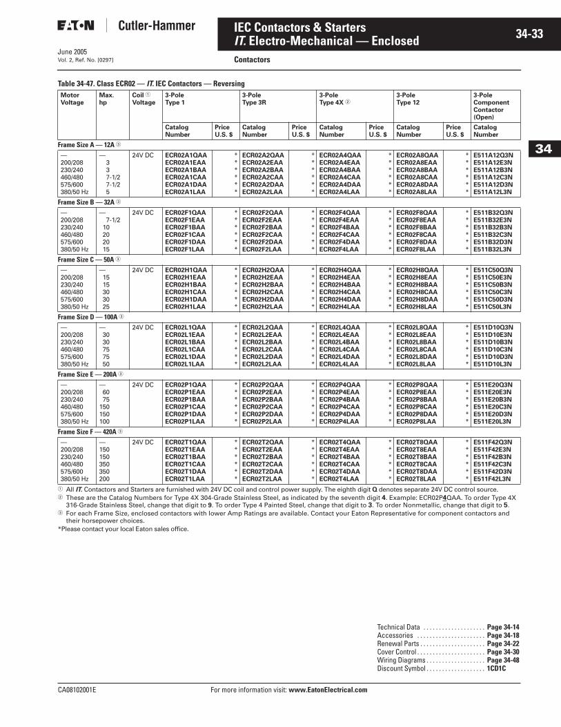
June 2005
CA08102001E For more information visit: www.EatonElectrical.com
34-33IEC Contactors & Starters
34
IT. Electro-Mechanical — EnclosedContactorsVol. 2, Ref. No. [0297]
Table 34-47. Class ECR02 — IT. IEC Contactors — Reversing
� All IT. Contactors and Starters are furnished with 24V DC coil and control power supply. The eighth digit Q denotes separate 24V DC control source. � These are the Catalog Numbers for Type 4X 304-Grade Stainless Steel, as indicated by the seventh digit 4. Example: ECR02P4QAA. To order Type 4X
316-Grade Stainless Steel, change that digit to 9. To order Type 4 Painted Steel, change that digit to 3. To order Nonmetallic, change that digit to 5.� For each Frame Size, enclosed contactors with lower Amp Ratings are available. Contact your Eaton Representative for component contactors and
their horsepower choices.*Please contact your local Eaton sales office.
MotorVoltage
Max.hp
Coil �
Voltage3-Pole Type 1
3-PoleType 3R
3-Pole Type 4X �
3-Pole Type 12
3-Pole ComponentContactor (Open)
CatalogNumber
PriceU.S. $
CatalogNumber
PriceU.S. $
CatalogNumber
PriceU.S. $
CatalogNumber
PriceU.S. $
CatalogNumber
Frame Size A — 12A �
—200/208230/240460/480575/600380/50 Hz
—337-1/27-1/25
24V DC ECR02A1QAAECR02A1EAAECR02A1BAAECR02A1CAAECR02A1DAAECR02A1LAA
******
ECR02A2QAAECR02A2EAAECR02A2BAAECR02A2CAAECR02A2DAAECR02A2LAA
******
ECR02A4QAAECR02A4EAAECR02A4BAAECR02A4CAAECR02A4DAAECR02A4LAA
******
ECR02A8QAAECR02A8EAAECR02A8BAAECR02A8CAAECR02A8DAAECR02A8LAA
******
E511A12Q3NE511A12E3NE511A12B3NE511A12C3NE511A12D3NE511A12L3N
Frame Size B — 32A �
—200/208230/240460/480575/600380/50 Hz
—7-1/2
10202015
24V DC ECR02F1QAAECR02F1EAAECR02F1BAAECR02F1CAAECR02F1DAAECR02F1LAA
******
ECR02F2QAAECR02F2EAAECR02F2BAAECR02F2CAAECR02F2DAAECR02F2LAA
******
ECR02F4QAAECR02F4EAAECR02F4BAAECR02F4CAAECR02F4DAAECR02F4LAA
******
ECR02F8QAAECR02F8EAAECR02F8BAAECR02F8CAAECR02F8DAAECR02F8LAA
******
E511B32Q3NE511B32E3NE511B32B3NE511B32C3NE511B32D3NE511B32L3N
Frame Size C — 50A �
—200/208230/240460/480575/600380/50 Hz
—1515303025
24V DC ECR02H1QAAECR02H1EAAECR02H1BAAECR02H1CAAECR02H1DAAECR02H1LAA
******
ECR02H2QAAECR02H2EAAECR02H2BAAECR02H2CAAECR02H2DAAECR02H2LAA
******
ECR02H4QAAECR02H4EAAECR02H4BAAECR02H4CAAECR02H4DAAECR02H4LAA
******
ECR02H8QAAECR02H8EAAECR02H8BAAECR02H8CAAECR02H8DAAECR02H8LAA
******
E511C50Q3NE511C50E3NE511C50B3NE511C50C3NE511C50D3NE511C50L3N
Frame Size D — 100A �
—200/208230/240460/480575/600380/50 Hz
—3030757550
24V DC ECR02L1QAAECR02L1EAAECR02L1BAAECR02L1CAAECR02L1DAAECR02L1LAA
******
ECR02L2QAAECR02L2EAAECR02L2BAAECR02L2CAAECR02L2DAAECR02L2LAA
******
ECR02L4QAAECR02L4EAAECR02L4BAAECR02L4CAAECR02L4DAAECR02L4LAA
******
ECR02L8QAAECR02L8EAAECR02L8BAAECR02L8CAAECR02L8DAAECR02L8LAA
******
E511D10Q3NE511D10E3NE511D10B3NE511D10C3NE511D10D3NE511D10L3N
Frame Size E — 200A �
—200/208230/240460/480575/600380/50 Hz
—6075
150150100
24V DC ECR02P1QAAECR02P1EAAECR02P1BAAECR02P1CAAECR02P1DAAECR02P1LAA
******
ECR02P2QAAECR02P2EAAECR02P2BAAECR02P2CAAECR02P2DAAECR02P2LAA
******
ECR02P4QAAECR02P4EAAECR02P4BAAECR02P4CAAECR02P4DAAECR02P4LAA
******
ECR02P8QAAECR02P8EAAECR02P8BAAECR02P8CAAECR02P8DAAECR02P8LAA
******
E511E20Q3NE511E20E3NE511E20B3NE511E20C3NE511E20D3NE511E20L3N
Frame Size F — 420A �
—200/208230/240460/480575/600380/50 Hz
—150150350350200
24V DC ECR02T1QAAECR02T1EAAECR02T1BAAECR02T1CAAECR02T1DAAECR02T1LAA
******
ECR02T2QAAECR02T2EAAECR02T2BAAECR02T2CAAECR02T2DAAECR02T2LAA
******
ECR02T4QAAECR02T4EAAECR02T4BAAECR02T4CAAECR02T4DAAECR02T4LAA
******
ECR02T8QAAECR02T8EAAECR02T8BAAECR02T8CAAECR02T8DAAECR02T8LAA
******
E511F42Q3NE511F42E3NE511F42B3NE511F42C3NE511F42D3NE511F42L3N
Technical Data . . . . . . . . . . . . . . . . . . . . Page 34-14Accessories . . . . . . . . . . . . . . . . . . . . . . Page 34-18Renewal Parts . . . . . . . . . . . . . . . . . . . . . Page 34-22Cover Control . . . . . . . . . . . . . . . . . . . . . . Page 34-30Wiring Diagrams . . . . . . . . . . . . . . . . . . . Page 34-48Discount Symbol . . . . . . . . . . . . . . . . . . . 1CD1C
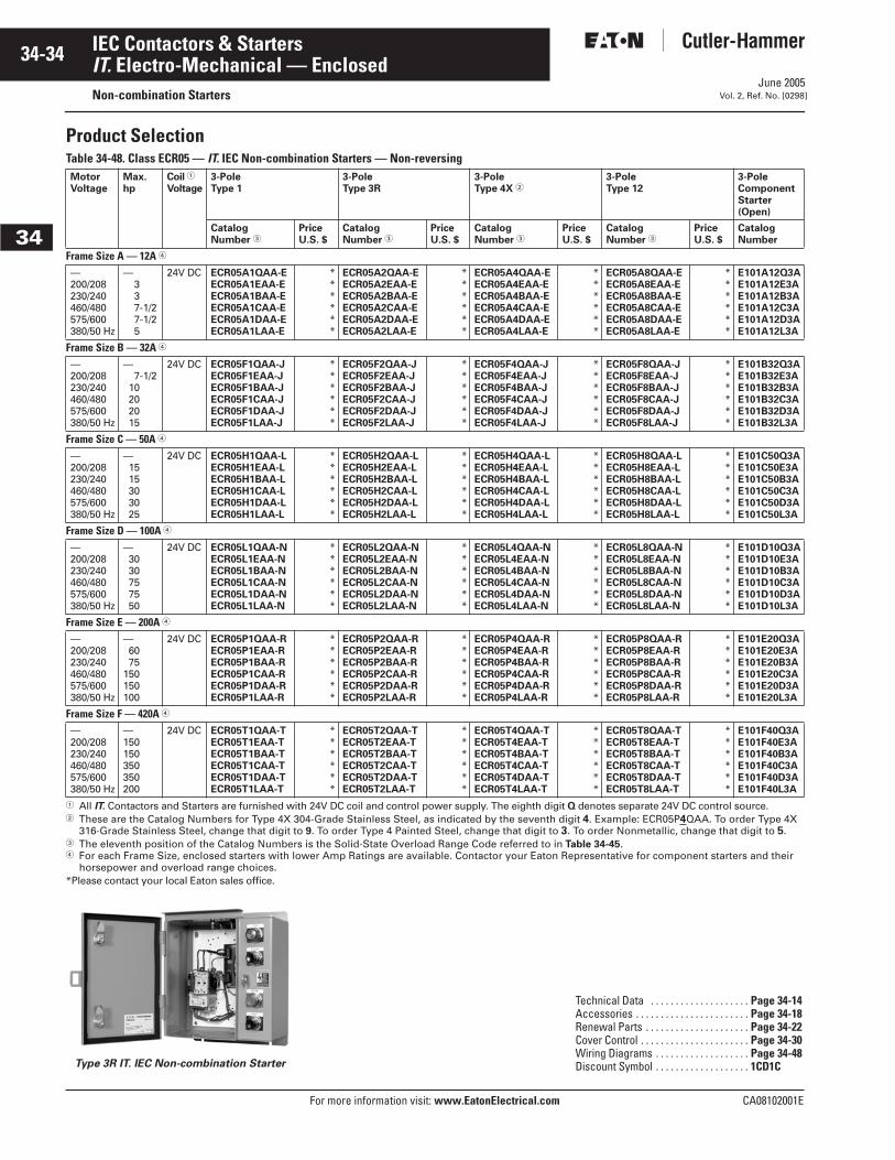
June 2005
34-34
For more information visit: www.EatonElectrical.com CA08102001E
IEC Contactors & Starters
34
IT. Electro-Mechanical — EnclosedNon-combination Starters Vol. 2, Ref. No. [0298]
Product SelectionTable 34-48. Class ECR05 — IT. IEC Non-combination Starters — Non-reversing
� All IT. Contactors and Starters are furnished with 24V DC coil and control power supply. The eighth digit Q denotes separate 24V DC control source.� These are the Catalog Numbers for Type 4X 304-Grade Stainless Steel, as indicated by the seventh digit 4. Example: ECR05P4QAA. To order Type 4X
316-Grade Stainless Steel, change that digit to 9. To order Type 4 Painted Steel, change that digit to 3. To order Nonmetallic, change that digit to 5.� The eleventh position of the Catalog Numbers is the Solid-State Overload Range Code referred to in Table 34-45.� For each Frame Size, enclosed starters with lower Amp Ratings are available. Contactor your Eaton Representative for component starters and their
horsepower and overload range choices.*Please contact your local Eaton sales office.
Type 3R IT. IEC Non-combination Starter
MotorVoltage
Max.hp
Coil �
Voltage3-PoleType 1
3-PoleType 3R
3-PoleType 4X �
3-PoleType 12
3-Pole ComponentStarter (Open)
Catalog Number �
PriceU.S. $
Catalog Number �
PriceU.S. $
Catalog Number �
PriceU.S. $
Catalog Number �
PriceU.S. $
CatalogNumber
Frame Size A — 12A �
—200/208230/240460/480575/600380/50 Hz
—337-1/27-1/25
24V DC ECR05A1QAA-EECR05A1EAA-EECR05A1BAA-EECR05A1CAA-EECR05A1DAA-EECR05A1LAA-E
******
ECR05A2QAA-EECR05A2EAA-EECR05A2BAA-EECR05A2CAA-EECR05A2DAA-EECR05A2LAA-E
******
ECR05A4QAA-EECR05A4EAA-EECR05A4BAA-EECR05A4CAA-EECR05A4DAA-EECR05A4LAA-E
******
ECR05A8QAA-EECR05A8EAA-EECR05A8BAA-EECR05A8CAA-EECR05A8DAA-EECR05A8LAA-E
******
E101A12Q3AE101A12E3AE101A12B3AE101A12C3AE101A12D3AE101A12L3A
Frame Size B — 32A �
—200/208230/240460/480575/600380/50 Hz
—7-1/2
10202015
24V DC ECR05F1QAA-JECR05F1EAA-JECR05F1BAA-JECR05F1CAA-JECR05F1DAA-JECR05F1LAA-J
******
ECR05F2QAA-JECR05F2EAA-JECR05F2BAA-JECR05F2CAA-JECR05F2DAA-JECR05F2LAA-J
******
ECR05F4QAA-JECR05F4EAA-JECR05F4BAA-JECR05F4CAA-JECR05F4DAA-JECR05F4LAA-J
******
ECR05F8QAA-JECR05F8EAA-JECR05F8BAA-JECR05F8CAA-JECR05F8DAA-JECR05F8LAA-J
******
E101B32Q3AE101B32E3AE101B32B3AE101B32C3AE101B32D3AE101B32L3A
Frame Size C — 50A �
—200/208230/240460/480575/600380/50 Hz
—1515303025
24V DC ECR05H1QAA-LECR05H1EAA-LECR05H1BAA-LECR05H1CAA-LECR05H1DAA-LECR05H1LAA-L
******
ECR05H2QAA-LECR05H2EAA-LECR05H2BAA-LECR05H2CAA-LECR05H2DAA-LECR05H2LAA-L
******
ECR05H4QAA-LECR05H4EAA-LECR05H4BAA-LECR05H4CAA-LECR05H4DAA-LECR05H4LAA-L
******
ECR05H8QAA-LECR05H8EAA-LECR05H8BAA-LECR05H8CAA-LECR05H8DAA-LECR05H8LAA-L
******
E101C50Q3AE101C50E3AE101C50B3AE101C50C3AE101C50D3AE101C50L3A
Frame Size D — 100A �
—200/208230/240460/480575/600380/50 Hz
—3030757550
24V DC ECR05L1QAA-NECR05L1EAA-NECR05L1BAA-NECR05L1CAA-NECR05L1DAA-NECR05L1LAA-N
******
ECR05L2QAA-NECR05L2EAA-NECR05L2BAA-NECR05L2CAA-NECR05L2DAA-NECR05L2LAA-N
******
ECR05L4QAA-NECR05L4EAA-NECR05L4BAA-NECR05L4CAA-NECR05L4DAA-NECR05L4LAA-N
******
ECR05L8QAA-NECR05L8EAA-NECR05L8BAA-NECR05L8CAA-NECR05L8DAA-NECR05L8LAA-N
******
E101D10Q3AE101D10E3AE101D10B3AE101D10C3AE101D10D3AE101D10L3A
Frame Size E — 200A �
—200/208230/240460/480575/600380/50 Hz
—6075
150150100
24V DC ECR05P1QAA-RECR05P1EAA-RECR05P1BAA-RECR05P1CAA-RECR05P1DAA-RECR05P1LAA-R
******
ECR05P2QAA-RECR05P2EAA-RECR05P2BAA-RECR05P2CAA-RECR05P2DAA-RECR05P2LAA-R
******
ECR05P4QAA-RECR05P4EAA-RECR05P4BAA-RECR05P4CAA-RECR05P4DAA-RECR05P4LAA-R
******
ECR05P8QAA-RECR05P8EAA-RECR05P8BAA-RECR05P8CAA-RECR05P8DAA-RECR05P8LAA-R
******
E101E20Q3AE101E20E3AE101E20B3AE101E20C3AE101E20D3AE101E20L3A
Frame Size F — 420A �
—200/208230/240460/480575/600380/50 Hz
—150150350350200
24V DC ECR05T1QAA-TECR05T1EAA-TECR05T1BAA-TECR05T1CAA-TECR05T1DAA-TECR05T1LAA-T
******
ECR05T2QAA-TECR05T2EAA-TECR05T2BAA-TECR05T2CAA-TECR05T2DAA-TECR05T2LAA-T
******
ECR05T4QAA-TECR05T4EAA-TECR05T4BAA-TECR05T4CAA-TECR05T4DAA-TECR05T4LAA-T
******
ECR05T8QAA-TECR05T8EAA-TECR05T8BAA-TECR05T8CAA-TECR05T8DAA-TECR05T8LAA-T
******
E101F40Q3AE101F40E3AE101F40B3AE101F40C3AE101F40D3AE101F40L3A
Technical Data . . . . . . . . . . . . . . . . . . . . Page 34-14Accessories . . . . . . . . . . . . . . . . . . . . . . . Page 34-18Renewal Parts . . . . . . . . . . . . . . . . . . . . . Page 34-22Cover Control . . . . . . . . . . . . . . . . . . . . . . Page 34-30Wiring Diagrams . . . . . . . . . . . . . . . . . . . Page 34-48Discount Symbol . . . . . . . . . . . . . . . . . . . 1CD1C
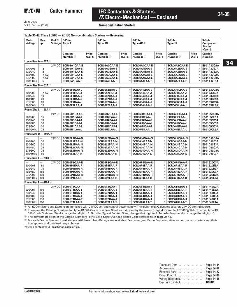
June 2005
CA08102001E For more information visit: www.EatonElectrical.com
34-35IEC Contactors & Starters
34
IT. Electro-Mechanical — EnclosedNon-combination StartersVol. 2, Ref. No. [0299]
Table 34-49. Class ECR06 — IT. IEC Non-combination Starters — Reversing
� All IT. Contactors and Starters are furnished with 24V DC coil and control power supply. The eighth digit Q denotes separate 24V DC control source.� These are the Catalog Numbers for Type 4X 304-Grade Stainless Steel, as indicated by the seventh digit 4. Example: ECR06P4QAA. To order Type 4X
316-Grade Stainless Steel, change that digit to 9. To order Type 4 Painted Steel, change that digit to 3. To order Nonmetallic, change that digit to 5.� The eleventh position of the Catalog Numbers is the Solid-State Overload Range Code referred to in Table 34-45.� For each Frame Size, enclosed starters with lower Amp Ratings are available. Contactor your Eaton Representative for component starters and their
horsepower and overload range choices.*Please contact your local Eaton sales office.
MotorVoltage
Max.hp
Coil �
Voltage3-Pole Type 1
3-Pole Type 3R
3-Pole Type 4X �
3-Pole Type 12
3-Pole ComponentStarter (Open)
Catalog Number �
PriceU.S. $
Catalog Number �
PriceU.S. $
Catalog Number �
PriceU.S. $
Catalog Number �
PriceU.S. $
CatalogNumber
Frame Size A — 12A �
—200/208230/240460/480575/600380/50 Hz
—337-1/27-1/25
24V DC ECR06A1QAA-EECR06A1EAA-EECR06A1BAA-EECR06A1CAA-EECR06A1DAA-EECR06A1LAA-E
******
ECR06A2QAA-EECR06A2EAA-EECR06A2BAA-EECR06A2CAA-EECR06A2DAA-EECR06A2LAA-E
******
ECR06A4QAA-EECR06A4EAA-EECR06A4BAA-EECR06A4CAA-EECR06A4DAA-EECR06A4LAA-E
******
ECR06A8QAA-EECR06A8EAA-EECR06A8BAA-EECR06A8CAA-EECR06A8DAA-EECR06A8LAA-E
******
E501A12Q3AE501A12E3AE501A12B3AE501A12C3AE501A12D3AE501A12L3A
Frame Size B — 32A �
—200/208230/240460/480575/600380/50 Hz
—7-1/2
10202015
24V DC ECR06F1QAA-JECR06F1EAA-JECR06F1BAA-JECR06F1CAA-JECR06F1DAA-JECR06F1LAA-J
******
ECR06F2QAA-JECR06F2EAA-JECR06F2BAA-JECR06F2CAA-JECR06F2DAA-JECR06F2LAA-J
******
ECR06F4QAA-JECR06F4EAA-JECR06F4BAA-JECR06F4CAA-JECR06F4DAA-JECR06F4LAA-J
******
ECR06F8QAA-JECR06F8EAA-JECR06F8BAA-JECR06F8CAA-JECR06F8DAA-JECR06F8LAA-J
******
E501B32Q3AE501B32E3AE501B32B3AE501B32C3AE501B32D3AE501B32L3A
Frame Size C — 50A �
—200/208230/240460/480575/600380/50 Hz
—1515303025
24V DC ECR06H1QAA-LECR06H1EAA-LECR06H1BAA-LECR06H1CAA-LECR06H1DAA-LECR06H1LAA-L
******
ECR06H2QAA-LECR06H2EAA-LECR06H2BAA-LECR06H2CAA-LECR06H2DAA-LECR06H2LAA-L
******
ECR06H4QAA-LECR06H4EAA-LECR06H4BAA-LECR06H4CAA-LECR06H4DAA-LECR06H4LAA-L
******
ECR06H8QAA-LECR06H8EAA-LECR06H8BAA-LECR06H8CAA-LECR06H8DAA-LECR06H8LAA-L
******
E501C50Q3AE501C50E3AE501C50B3AE501C50C3AE501C50D3AE501C50L3A
Frame Size D — 100A �
—200/208230/240460/480575/600380/50 Hz
—3030757550
24V DC ECR06L1QAA-NECR06L1EAA-NECR06L1BAA-NECR06L1CAA-NECR06L1DAA-NECR06L1LAA-N
******
ECR06L2QAA-NECR06L2EAA-NECR06L2BAA-NECR06L2CAA-NECR06L2DAA-NECR06L2LAA-N
******
ECR06L4QAA-NECR06L4EAA-NECR06L4BAA-NECR06L4CAA-NECR06L4DAA-NECR06L4LAA-N
******
ECR06L8QAA-NECR06L8EAA-NECR06L8BAA-NECR06L8CAA-NECR06L8DAA-NECR06L8LAA-N
******
E501D10Q3AE501D10E3AE501D10B3AE501D10C3AE501D10D3AE501D10L3A
Frame Size E — 200A �
—200/208230/240460/480575/600380/50 Hz
—6075
150150100
24V DC ECR06P1QAA-RECR06P1EAA-RECR06P1BAA-RECR06P1CAA-RECR06P1DAA-RECR06P1LAA-R
******
ECR06P2QAA-RECR06P2EAA-RECR06P2BAA-RECR06P2CAA-RECR06P2DAA-RECR06P2LAA-R
******
ECR06P4QAA-RECR06P4EAA-RECR06P4BAA-RECR06P4CAA-RECR06P4DAA-RECR06P4LAA-R
******
ECR06P8QAA-RECR06P8EAA-RECR06P8BAA-RECR06P8CAA-RECR06P8DAA-RECR06P8LAA-R
******
E501E20Q3AE501E20E3AE501E20B3AE501E20C3AE501E20D3AE501E20L3A
Frame Size F — 420A �
—200/208230/240460/480575/600380/50 Hz
—150150350350200
24V DC ECR06T1QAA-TECR06T1EAA-TECR06T1BAA-TECR06T1CAA-TECR06T1DAA-TECR06T1LAA-T
******
ECR06T2QAA-TECR06T2EAA-TECR06T2BAA-TECR06T2CAA-TECR06T2DAA-TECR06T2LAA-T
******
ECR06T4QAA-TECR06T4EAA-TECR06T4BAA-TECR06T4CAA-TECR06T4DAA-TECR06T4LAA-T
******
ECR06T8QAA-TECR06T8EAA-TECR06T8BAA-TECR06T8CAA-TECR06T8DAA-TECR06T8LAA-T
******
E501F40Q3AE501F40E3AE501F40B3AE501F40C3AE501F40D3AE501F40L3A
Technical Data . . . . . . . . . . . . . . . . . . . . Page 34-14Accessories . . . . . . . . . . . . . . . . . . . . . . Page 34-18Renewal Parts . . . . . . . . . . . . . . . . . . . . . Page 34-22Cover Control . . . . . . . . . . . . . . . . . . . . . . Page 34-30Wiring Diagrams . . . . . . . . . . . . . . . . . . . Page 34-48Discount Symbol . . . . . . . . . . . . . . . . . . . 1CD1C
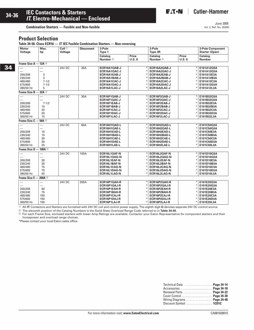
June 2005
34-36
For more information visit: www.EatonElectrical.com CA08102001E
IEC Contactors & Starters
34
IT. Electro-Mechanical — EnclosedCombination Starters — Fusible and Non-fusible Vol. 2, Ref. No. [0300]
Product SelectionTable 34-50. Class ECR16 — IT. IEC Fusible Combination Starters — Non-reversing
� All IT. Contactors and Starters are furnished with 24V DC coil and control power supply. The eighth digit Q denotes separate 24V DC control source.� The eleventh position of the Catalog Numbers is the Solid-State Overload Range Code referred to in Table 34-45.� For each Frame Size, enclosed starters with lower Amp Ratings are available. Contactor your Eaton Representative for component starters and their
horsepower and overload range choices.*Please contact your local Eaton sales office.
MotorVoltage
Max.hp
Coil �
VoltageDisconnect 3-Pole
Type 13-Pole Type 3R
3-Pole ComponentStarter (Open)
CatalogNumber �
PriceU.S. $
Catalog Number �
PriceU.S. $
CatalogNumber
Frame Size A — 12A �
——200/208230/240460/480575/600380/50 Hz
——
337-1/27-1/25
24V DC 30A ECR16A1QAB-JECR16A1QAC-JECR16A1EAB-JECR16A1BAB-JECR16A1CAC-JECR16A1DAC-JECR16A1LAC-J
*******
ECR16A2QAB-JECR16A2QAC-JECR16A2EAB-JECR16A2BAB-JECR16A2CAC-JECR16A2DAC-JECR16A2LAC-J
*******
E101A12Q3AE101A12Q3AE101A12E3AE101A12B3AE101A12C3AE101A12D3AE101A12L3A
Frame Size B — 32A �
——200/208230/240460/480575/600380/50 Hz
——
7-1/210202015
24V DC 30A ECR16F1QAB-JECR16F1QAC-JECR16F1EAB-JECR16F1BAB-JECR16F1CAC-JECR16F1DAC-JECR16F1LAC-J
*******
ECR16F2QAB-JECR16F2QAC-JECR16F2EAB-JECR16F2BAB-JECR16F2CAC-JECR16F2DAC-JECR16F2LAC-J
*******
E101B32Q3AE101B32Q3AE101B32E3AE101B32B3AE101B32C3AE101B32D3AE101B32L3A
Frame Size C — 50A �
——200/208230/240460/480575/600380/50 Hz
——1515303025
24V DC 60A ECR16H1QAD-LECR16H1QAE-LECR16H1EAD-LECR16H1BAD-LECR16H1CAE-LECR16H1DAE-LECR16H1LAE-L
*******
ECR16H2QAD-LECR16H2QAE-LECR16H2EAD-LECR16H2BAD-LECR16H2CAE-LECR16H2DAE-LECR16H2LAE-L
*******
E101C50Q3AE101C50Q3AE101C50E3AE101C50B3AE101C50C3AE101C50D3AE101C50L3A
Frame Size D — 100A �
——200/208230/240460/480575/600380/50 Hz
——3030757550
24V DC 100A ECR16L1QAF-NECR16L1QAG-NECR16L1EAF-NECR16L1BAF-NECR16L1CAG-NECR16L1DAG-NECR16L1LAG-N
*******
ECR16L2QAF-NECR16L2QAG-NECR16L2EAF-NECR16L2BAF-NECR16L2CAG-NECR16L2DAG-NECR16L2LAG-N
*******
E101D10Q3AE101D10Q3AE101D10E3AE101D10B3AE101D10C3AE101D10D3AE101D10L3A
Frame Size E — 200A �
——200/208230/240460/480575/600380/50 Hz
——6075
150150100
24V DC 200A ECR16P1QAH-RECR16P1QAJ-RECR16P1EAH-RECR16P1BAH-RECR16P1CAJ-RECR16P1DAJ-RECR16P1LAJ-R
*******
ECR16P2QAH-RECR16P2QAJ-RECR16P2EAH-RECR16P2BAH-RECR16P2CAJ-RECR16P2DAJ-RECR16P2LAJ-R
*******
E101E20Q3AE101E20Q3AE101E20E3AE101E20B3AE101E20C3AE101E20D3AE101E20L3A
Technical Data . . . . . . . . . . . . . . . . . . . . Page 34-14Accessories . . . . . . . . . . . . . . . . . . . . . . . Page 34-18Renewal Parts . . . . . . . . . . . . . . . . . . . . . Page 34-22Cover Control . . . . . . . . . . . . . . . . . . . . . . Page 34-30Wiring Diagrams . . . . . . . . . . . . . . . . . . . Page 34-48Discount Symbol . . . . . . . . . . . . . . . . . . . 1CD1C

June 2005
CA08102001E For more information visit: www.EatonElectrical.com
34-37IEC Contactors & Starters
34
IT. Electro-Mechanical — EnclosedCombination Starters — Fusible and Non-fusibleVol. 2, Ref. No. [0301]
Table 34-50. Class ECR16 — IT. IEC Fusible Combination Starters — Non-reversing (Continued)
� All IT. Contactors and Starters are furnished with 24V DC coil and control power supply. The eighth digit Q denotes separate 24V DC control source.� These are the Catalog Numbers for Type 4X 304-Grade Stainless Steel, as indicated by the seventh digit 4. Example: ECR16P4QAB. To order Type 4X
316-Grade Stainless Steel, change that digit to 9. To order Type 4 Painted Steel, change that digit to 3. To order Nonmetallic, change that digit to 5.� The eleventh position of the Catalog Numbers is the Solid-State Overload Range Code referred to in Table 34-45.� For each Frame Size, enclosed starters with lower Amp Ratings are available. Contactor your Eaton Representative for component starters and their
horsepower and overload range choices.*Please contact your local Eaton sales office.
Type 12 IT. IEC Fusible Combination Starter
MotorVoltage
Max.hp
Coil �
VoltageDisconnect 3-Pole
Type 4X �3-Pole Type 12
3-Pole ComponentStarter (Open)
Catalog Number �
PriceU.S. $
Catalog Number �
PriceU.S. $
CatalogNumber
Frame Size A — 12A �
——200/208230/240460/480575/600380/50 Hz
——
337-1/27-1/25
24V DC 30A ECR16A4QAB-JECR16A4QAC-JECR16A4EAB-JECR16A4BAB-JECR16A4CAC-JECR16A4DAC-JECR16A4LAC-J
*******
ECR16A8QAB-JECR16A8QAC-JECR16A8EAB-JECR16A8BAB-JECR16A8CAC-JECR16A8DAC-JECR16A8LAC-J
*******
E101A12Q3AE101A12Q3AE101A12E3AE101A12B3AE101A12C3AE101A12D3AE101A12L3A
Frame Size B — 32A �
——200/208230/240460/480575/600380/50 Hz
——
7-1/210202015
24V DC 30A ECR16F4QAB-JECR16F4QAC-JECR16F4EAB-JECR16F4BAB-JECR16F4CAC-JECR16F4DAC-JECR16F4LAC-J
*******
ECR16F8QAB-JECR16F8QAC-JECR16F8EAB-JECR16F8BAB-JECR16F8CAC-JECR16F8DAC-JECR16F8LAC-J
*******
E101B32Q3AE101B32Q3AE101B32E3AE101B32B3AE101B32C3AE101B32D3AE101B32L3A
Frame Size C — 50A �
——200/208230/240460/480575/600380/50 Hz
——1515303025
24V DC 60A ECR16H4QAD-LECR16H4QAE-LECR16H4EAD-LECR16H4BAD-LECR16H4CAE-LECR16H4DAE-LECR16H4LAE-L
*******
ECR16H8QAD-LECR16H8QAE-LECR16H8EAD-LECR16H8BAD-LECR16H8CAE-LECR16H8DAE-LECR16H8LAE-L
*******
E101C50Q3AE101C50Q3AE101C50E3AE101C50B3AE101C50C3AE101C50D3AE101C50L3A
Frame Size D — 100A �
——200/208230/240460/480575/600380/50 Hz
——3030757550
24V DC 100A ECR16L4QAF-NECR16L4QAG-NECR16L4EAF-NECR16L4BAF-NECR16L4CAG-NECR16L4DAG-NECR16L4LAG-N
*******
ECR16L8QAF-NECR16L8QAG-NECR16L8EAF-NECR16L8BAF-NECR16L8CAG-NECR16L8DAG-NECR16L8LAG-N
*******
E101D10Q3AE101D10Q3AE101D10E3AE101D10B3AE101D10C3AE101D10D3AE101D10L3A
Frame Size E — 200A �
——200/208230/240460/480575/600380/50 Hz
——6075
150150100
24V DC 200A ECR16P4QAH-RECR16P4QAJ-RECR16P4EAH-RECR16P4BAH-RECR16P4CAJ-RECR16P4DAJ-RECR16P4LAJ-R
*******
ECR16P8QAH-RECR16P8QAJ-RECR16P8EAH-RECR16P8BAH-RECR16P8CAJ-RECR16P8DAJ-RECR16P8LAJ-R
*******
E101E20Q3AE101E20Q3AE101E20E3AE101E20B3AE101E20C3AE101E20D3AE101E20L3A
Technical Data . . . . . . . . . . . . . . . . . . . . Page 34-14Accessories . . . . . . . . . . . . . . . . . . . . . . Page 34-18Renewal Parts . . . . . . . . . . . . . . . . . . . . . Page 34-22Cover Control . . . . . . . . . . . . . . . . . . . . . . Page 34-30Wiring Diagrams . . . . . . . . . . . . . . . . . . . Page 34-48Discount Symbol . . . . . . . . . . . . . . . . . . . 1CD1C
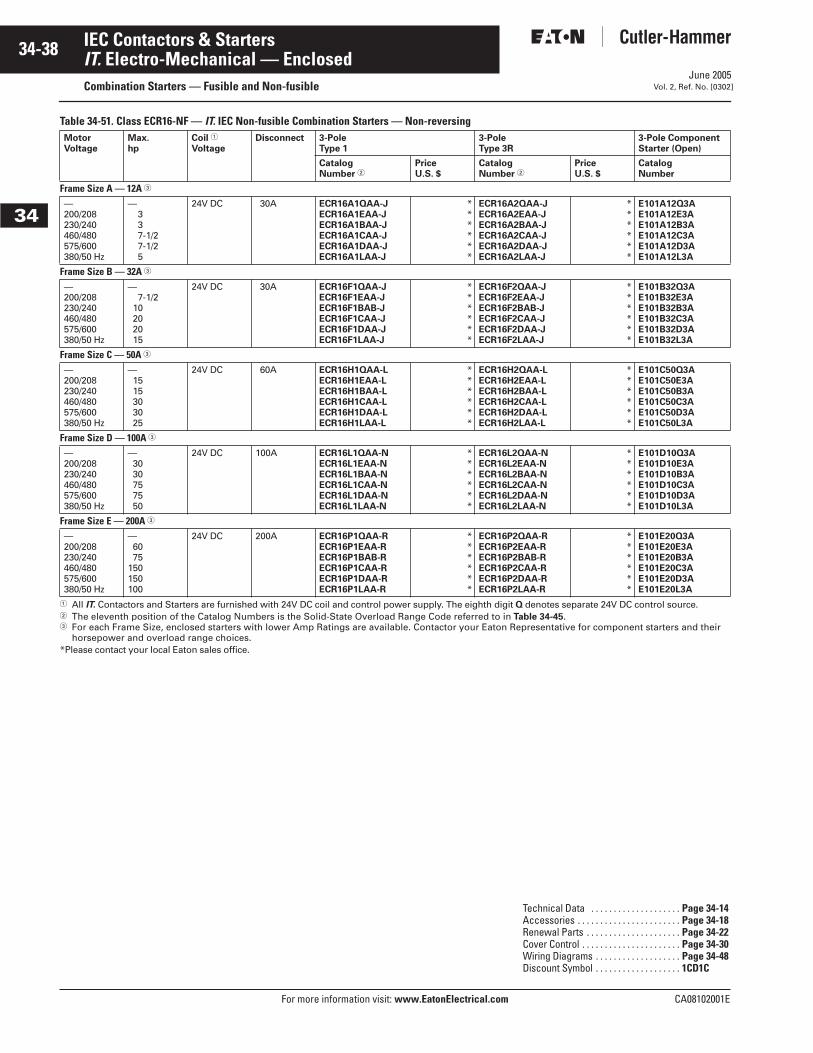
June 2005
34-38
For more information visit: www.EatonElectrical.com CA08102001E
IEC Contactors & Starters
34
IT. Electro-Mechanical — EnclosedCombination Starters — Fusible and Non-fusible Vol. 2, Ref. No. [0302]
Table 34-51. Class ECR16-NF — IT. IEC Non-fusible Combination Starters — Non-reversing
� All IT. Contactors and Starters are furnished with 24V DC coil and control power supply. The eighth digit Q denotes separate 24V DC control source.� The eleventh position of the Catalog Numbers is the Solid-State Overload Range Code referred to in Table 34-45.� For each Frame Size, enclosed starters with lower Amp Ratings are available. Contactor your Eaton Representative for component starters and their
horsepower and overload range choices.*Please contact your local Eaton sales office.
MotorVoltage
Max.hp
Coil �
VoltageDisconnect 3-Pole
Type 13-PoleType 3R
3-Pole ComponentStarter (Open)
Catalog Number �
PriceU.S. $
Catalog Number �
PriceU.S. $
CatalogNumber
Frame Size A — 12A �
—200/208230/240460/480575/600380/50 Hz
—337-1/27-1/25
24V DC 30A ECR16A1QAA-JECR16A1EAA-JECR16A1BAA-JECR16A1CAA-JECR16A1DAA-JECR16A1LAA-J
******
ECR16A2QAA-JECR16A2EAA-JECR16A2BAA-JECR16A2CAA-JECR16A2DAA-JECR16A2LAA-J
******
E101A12Q3AE101A12E3AE101A12B3AE101A12C3AE101A12D3AE101A12L3A
Frame Size B — 32A �
—200/208230/240460/480575/600380/50 Hz
—7-1/2
10202015
24V DC 30A ECR16F1QAA-JECR16F1EAA-JECR16F1BAB-JECR16F1CAA-JECR16F1DAA-JECR16F1LAA-J
******
ECR16F2QAA-JECR16F2EAA-JECR16F2BAB-JECR16F2CAA-JECR16F2DAA-JECR16F2LAA-J
******
E101B32Q3AE101B32E3AE101B32B3AE101B32C3AE101B32D3AE101B32L3A
Frame Size C — 50A �
—200/208230/240460/480575/600380/50 Hz
—1515303025
24V DC 60A ECR16H1QAA-LECR16H1EAA-LECR16H1BAA-LECR16H1CAA-LECR16H1DAA-LECR16H1LAA-L
******
ECR16H2QAA-LECR16H2EAA-LECR16H2BAA-LECR16H2CAA-LECR16H2DAA-LECR16H2LAA-L
******
E101C50Q3AE101C50E3AE101C50B3AE101C50C3AE101C50D3AE101C50L3A
Frame Size D — 100A �
—200/208230/240460/480575/600380/50 Hz
—3030757550
24V DC 100A ECR16L1QAA-NECR16L1EAA-NECR16L1BAA-NECR16L1CAA-NECR16L1DAA-NECR16L1LAA-N
******
ECR16L2QAA-NECR16L2EAA-NECR16L2BAA-NECR16L2CAA-NECR16L2DAA-NECR16L2LAA-N
******
E101D10Q3AE101D10E3AE101D10B3AE101D10C3AE101D10D3AE101D10L3A
Frame Size E — 200A �
—200/208230/240460/480575/600380/50 Hz
—6075
150150100
24V DC 200A ECR16P1QAA-RECR16P1EAA-RECR16P1BAB-RECR16P1CAA-RECR16P1DAA-RECR16P1LAA-R
******
ECR16P2QAA-RECR16P2EAA-RECR16P2BAB-RECR16P2CAA-RECR16P2DAA-RECR16P2LAA-R
******
E101E20Q3AE101E20E3AE101E20B3AE101E20C3AE101E20D3AE101E20L3A
Technical Data . . . . . . . . . . . . . . . . . . . . Page 34-14Accessories . . . . . . . . . . . . . . . . . . . . . . . Page 34-18Renewal Parts . . . . . . . . . . . . . . . . . . . . . Page 34-22Cover Control . . . . . . . . . . . . . . . . . . . . . . Page 34-30Wiring Diagrams . . . . . . . . . . . . . . . . . . . Page 34-48Discount Symbol . . . . . . . . . . . . . . . . . . . 1CD1C
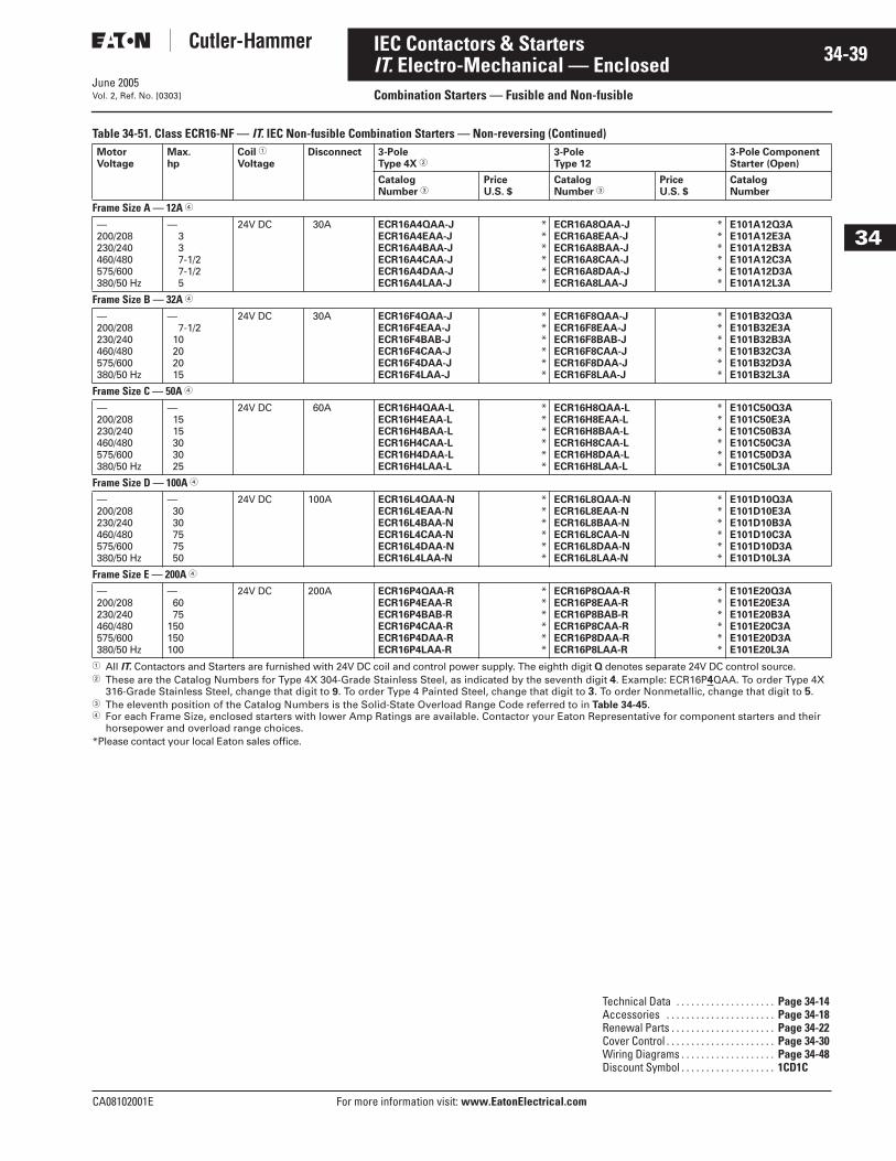
June 2005
CA08102001E For more information visit: www.EatonElectrical.com
34-39IEC Contactors & Starters
34
IT. Electro-Mechanical — EnclosedCombination Starters — Fusible and Non-fusibleVol. 2, Ref. No. [0303]
Table 34-51. Class ECR16-NF — IT. IEC Non-fusible Combination Starters — Non-reversing (Continued)
� All IT. Contactors and Starters are furnished with 24V DC coil and control power supply. The eighth digit Q denotes separate 24V DC control source.� These are the Catalog Numbers for Type 4X 304-Grade Stainless Steel, as indicated by the seventh digit 4. Example: ECR16P4QAA. To order Type 4X
316-Grade Stainless Steel, change that digit to 9. To order Type 4 Painted Steel, change that digit to 3. To order Nonmetallic, change that digit to 5.� The eleventh position of the Catalog Numbers is the Solid-State Overload Range Code referred to in Table 34-45.� For each Frame Size, enclosed starters with lower Amp Ratings are available. Contactor your Eaton Representative for component starters and their
horsepower and overload range choices.*Please contact your local Eaton sales office.
MotorVoltage
Max.hp
Coil �
VoltageDisconnect 3-Pole
Type 4X �3-PoleType 12
3-Pole ComponentStarter (Open)
Catalog Number �
PriceU.S. $
Catalog Number �
PriceU.S. $
CatalogNumber
Frame Size A — 12A �
—200/208230/240460/480575/600380/50 Hz
—337-1/27-1/25
24V DC 30A ECR16A4QAA-JECR16A4EAA-JECR16A4BAA-JECR16A4CAA-JECR16A4DAA-JECR16A4LAA-J
******
ECR16A8QAA-JECR16A8EAA-JECR16A8BAA-JECR16A8CAA-JECR16A8DAA-JECR16A8LAA-J
******
E101A12Q3AE101A12E3AE101A12B3AE101A12C3AE101A12D3AE101A12L3A
Frame Size B — 32A �
—200/208230/240460/480575/600380/50 Hz
—7-1/2
10202015
24V DC 30A ECR16F4QAA-JECR16F4EAA-JECR16F4BAB-JECR16F4CAA-JECR16F4DAA-JECR16F4LAA-J
******
ECR16F8QAA-JECR16F8EAA-JECR16F8BAB-JECR16F8CAA-JECR16F8DAA-JECR16F8LAA-J
******
E101B32Q3AE101B32E3AE101B32B3AE101B32C3AE101B32D3AE101B32L3A
Frame Size C — 50A �
—200/208230/240460/480575/600380/50 Hz
—1515303025
24V DC 60A ECR16H4QAA-LECR16H4EAA-LECR16H4BAA-LECR16H4CAA-LECR16H4DAA-LECR16H4LAA-L
******
ECR16H8QAA-LECR16H8EAA-LECR16H8BAA-LECR16H8CAA-LECR16H8DAA-LECR16H8LAA-L
******
E101C50Q3AE101C50E3AE101C50B3AE101C50C3AE101C50D3AE101C50L3A
Frame Size D — 100A �
—200/208230/240460/480575/600380/50 Hz
—3030757550
24V DC 100A ECR16L4QAA-NECR16L4EAA-NECR16L4BAA-NECR16L4CAA-NECR16L4DAA-NECR16L4LAA-N
******
ECR16L8QAA-NECR16L8EAA-NECR16L8BAA-NECR16L8CAA-NECR16L8DAA-NECR16L8LAA-N
******
E101D10Q3AE101D10E3AE101D10B3AE101D10C3AE101D10D3AE101D10L3A
Frame Size E — 200A �
—200/208230/240460/480575/600380/50 Hz
—6075
150150100
24V DC 200A ECR16P4QAA-RECR16P4EAA-RECR16P4BAB-RECR16P4CAA-RECR16P4DAA-RECR16P4LAA-R
******
ECR16P8QAA-RECR16P8EAA-RECR16P8BAB-RECR16P8CAA-RECR16P8DAA-RECR16P8LAA-R
******
E101E20Q3AE101E20E3AE101E20B3AE101E20C3AE101E20D3AE101E20L3A
Technical Data . . . . . . . . . . . . . . . . . . . . Page 34-14Accessories . . . . . . . . . . . . . . . . . . . . . . Page 34-18Renewal Parts . . . . . . . . . . . . . . . . . . . . . Page 34-22Cover Control . . . . . . . . . . . . . . . . . . . . . . Page 34-30Wiring Diagrams . . . . . . . . . . . . . . . . . . . Page 34-48Discount Symbol . . . . . . . . . . . . . . . . . . . 1CD1C
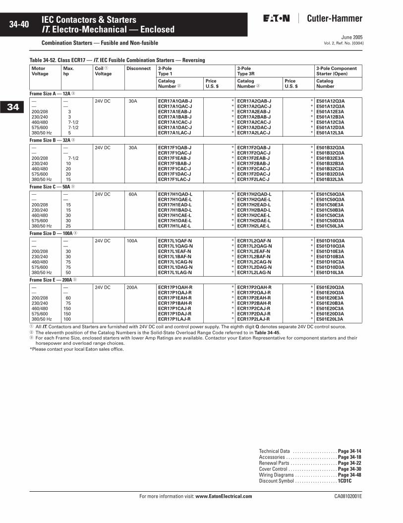
June 2005
34-40
For more information visit: www.EatonElectrical.com CA08102001E
IEC Contactors & Starters
34
IT. Electro-Mechanical — EnclosedCombination Starters — Fusible and Non-fusible Vol. 2, Ref. No. [0304]
Table 34-52. Class ECR17 — IT. IEC Fusible Combination Starters — Reversing
� All IT. Contactors and Starters are furnished with 24V DC coil and control power supply. The eighth digit Q denotes separate 24V DC control source.� The eleventh position of the Catalog Numbers is the Solid-State Overload Range Code referred to in Table 34-45.� For each Frame Size, enclosed starters with lower Amp Ratings are available. Contactor your Eaton Representative for component starters and their
horsepower and overload range choices.*Please contact your local Eaton sales office.
MotorVoltage
Max.hp
Coil �
VoltageDisconnect 3-Pole
Type 13-PoleType 3R
3-Pole ComponentStarter (Open)
Catalog Number �
PriceU.S. $
Catalog Number �
PriceU.S. $
CatalogNumber
Frame Size A — 12A �
——200/208230/240460/480575/600380/50 Hz
——
337-1/27-1/25
24V DC 30A ECR17A1QAB-JECR17A1QAC-JECR17A1EAB-JECR17A1BAB-JECR17A1CAC-JECR17A1DAC-JECR17A1LAC-J
*******
ECR17A2QAB-JECR17A2QAC-JECR17A2EAB-JECR17A2BAB-JECR17A2CAC-JECR17A2DAC-JECR17A2LAC-J
*******
E501A12Q3AE501A12Q3AE501A12E3AE501A12B3AE501A12C3AE501A12D3AE501A12L3A
Frame Size B — 32A �
——200/208230/240460/480575/600380/50 Hz
——
7-1/210202015
24V DC 30A ECR17F1QAB-JECR17F1QAC-JECR17F1EAB-JECR17F1BAB-JECR17F1CAC-JECR17F1DAC-JECR17F1LAC-J
*******
ECR17F2QAB-JECR17F2QAC-JECR17F2EAB-JECR17F2BAB-JECR17F2CAC-JECR17F2DAC-JECR17F2LAC-J
*******
E501B32Q3AE501B32Q3AE501B32E3AE501B32B3AE501B32C3AE501B32D3AE501B32L3A
Frame Size C — 50A �
——200/208230/240460/480575/600380/50 Hz
——1515303025
24V DC 60A ECR17H1QAD-LECR17H1QAE-LECR17H1EAD-LECR17H1BAD-LECR17H1CAE-LECR17H1DAE-LECR17H1LAE-L
*******
ECR17H2QAD-LECR17H2QAE-LECR17H2EAD-LECR17H2BAD-LECR17H2CAE-LECR17H2DAE-LECR17H2LAE-L
*******
E501C50Q3AE501C50Q3AE501C50E3AE501C50B3AE501C50C3AE501C50D3AE501C50L3A
Frame Size D — 100A �
——200/208230/240460/480575/600380/50 Hz
——3030757550
24V DC 100A ECR17L1QAF-NECR17L1QAG-NECR17L1EAF-NECR17L1BAF-NECR17L1CAG-NECR17L1DAG-NECR17L1LAG-N
*******
ECR17L2QAF-NECR17L2QAG-NECR17L2EAF-NECR17L2BAF-NECR17L2CAG-NECR17L2DAG-NECR17L2LAG-N
*******
E501D10Q3AE501D10Q3AE501D10E3AE501D10B3AE501D10C3AE501D10D3AE501D10L3A
Frame Size E — 200A �
——200/208230/240460/480575/600380/50 Hz
——6075
150150100
24V DC 200A ECR17P1QAH-RECR17P1QAJ-RECR17P1EAH-RECR17P1BAH-RECR17P1CAJ-RECR17P1DAJ-RECR17P1LAJ-R
*******
ECR17P2QAH-RECR17P2QAJ-RECR17P2EAH-RECR17P2BAH-RECR17P2CAJ-RECR17P2DAJ-RECR17P2LAJ-R
*******
E501E20Q3AE501E20Q3AE501E20E3AE501E20B3AE501E20C3AE501E20D3AE501E20L3A
Technical Data . . . . . . . . . . . . . . . . . . . . Page 34-14Accessories . . . . . . . . . . . . . . . . . . . . . . . Page 34-18Renewal Parts . . . . . . . . . . . . . . . . . . . . . Page 34-22Cover Control . . . . . . . . . . . . . . . . . . . . . . Page 34-30Wiring Diagrams . . . . . . . . . . . . . . . . . . . Page 34-48Discount Symbol . . . . . . . . . . . . . . . . . . . 1CD1C

June 2005
CA08102001E For more information visit: www.EatonElectrical.com
34-41IEC Contactors & Starters
34
IT. Electro-Mechanical — EnclosedCombination Starters — Fusible and Non-fusibleVol. 2, Ref. No. [0305]
Table 34-52. Class ECR17 — IT. IEC Fusible Combination Starters — Reversing (Continued)
� All IT. Contactors and Starters are furnished with 24V DC coil and control power supply. The eighth digit Q denotes separate 24V DC control source.� These are the Catalog Numbers for Type 4X 304-Grade Stainless Steel, as indicated by the seventh digit 4. Example: ECR17P4QAB. To order Type 4X
316-Grade Stainless Steel, change that digit to 9. To order Type 4 Painted Steel, change that digit to 3. To order Nonmetallic, change that digit to 5.� The eleventh position of the Catalog Numbers is the Solid-State Overload Range Code referred to in Table 34-45.� For each Frame Size, enclosed starters with lower Amp Ratings are available. Contactor your Eaton Representative for component starters and their
horsepower and overload range choices.*Please contact your local Eaton sales office.
MotorVoltage
Max.hp
Coil �
VoltageDisconnect 3-Pole
Type 4X �3-PoleType 12
3-Pole ComponentStarter (Open)
Catalog Number �
PriceU.S. $
Catalog Number �
PriceU.S. $
CatalogNumber
Frame Size A — 12A �
——200/208230/240460/480575/600380/50 Hz
——
337-1/27-1/25
24V DC 30A ECR17A4QAB-JECR17A4QAC-JECR17A4EAB-JECR17A4BAB-JECR17A4CAC-JECR17A4DAC-JECR17A4LAC-J
*******
ECR17A8QAB-JECR17A8QAC-JECR17A8EAB-JECR17A8BAB-JECR17A8CAC-JECR17A8DAC-JECR17A8LAC-J
*******
E501A12Q3AE501A12Q3AE501A12E3AE501A12B3AE501A12C3AE501A12D3AE501A12L3A
Frame Size B — 32A �
——200/208230/240460/480575/600380/50 Hz
——
7-1/210202015
24V DC 30A ECR17F4QAB-JECR17F4QAC-JECR17F4EAB-JECR17F4BAB-JECR17F4CAC-JECR17F4DAC-JECR17F4LAC-J
*******
ECR17F8QAB-JECR17F8QAC-JECR17F8EAB-JECR17F8BAB-JECR17F8CAC-JECR17F8DAC-JECR17F8LAC-J
*******
E501B32Q3AE501B32Q3AE501B32E3AE501B32B3AE501B32C3AE501B32D3AE501B32L3A
Frame Size C — 50A �
——200/208230/240460/480575/600380/50 Hz
——1515303025
24V DC 60A ECR17H4QAD-LECR17H4QAE-LECR17H4EAD-LECR17H4BAD-LECR17H4CAE-LECR17H4DAE-LECR17H4LAE-L
*******
ECR17H8QAD-LECR17H8QAE-LECR17H8EAD-LECR17H8BAD-LECR17H8CAE-LECR17H8DAE-LECR17H8LAE-L
*******
E501C50Q3AE501C50Q3AE501C50E3AE501C50B3AE501C50C3AE501C50D3AE501C50L3A
Frame Size D — 100A �
——200/208230/240460/480575/600380/50 Hz
——3030757550
24V DC 100A ECR17L4QAF-NECR17L4QAG-NECR17L4EAF-NECR17L4BAF-NECR17L4CAG-NECR17L4DAG-NECR17L4LAG-N
*******
ECR17L8QAF-NECR17L8QAG-NECR17L8EAF-NECR17L8BAF-NECR17L8CAG-NECR17L8DAG-NECR17L8LAG-N
*******
E501D10Q3AE501D10Q3AE501D10E3AE501D10B3AE501D10C3AE501D10D3AE501D10L3A
Frame Size E — 200A �
——200/208230/240460/480575/600380/50 Hz
——6075
150150100
24V DC 200A ECR17P4QAH-RECR17P4QAJ-RECR17P4EAH-RECR17P4BAH-RECR17P4CAJ-RECR17P4DAJ-RECR17P4LAJ-R
*******
ECR17P8QAH-RECR17P8QAJ-RECR17P8EAH-RECR17P8BAH-RECR17P8CAJ-RECR17P8DAJ-RECR17P8LAJ-R
*******
E501E20Q3AE501E20Q3AE501E20E3AE501E20B3AE501E20C3AE501E20D3AE501E20L3A
Technical Data . . . . . . . . . . . . . . . . . . . . Page 34-14Accessories . . . . . . . . . . . . . . . . . . . . . . Page 34-18Renewal Parts . . . . . . . . . . . . . . . . . . . . . Page 34-22Cover Control . . . . . . . . . . . . . . . . . . . . . . Page 34-30Wiring Diagrams . . . . . . . . . . . . . . . . . . . Page 34-48Discount Symbol . . . . . . . . . . . . . . . . . . . 1CD1C

June 2005
34-42
For more information visit: www.EatonElectrical.com CA08102001E
IEC Contactors & Starters
34
IT. Electro-Mechanical — EnclosedCombination Starters — Fusible and Non-fusible Vol. 2, Ref. No. [0306]
Table 34-53. Class ECR17-NF — IT. IEC Non-fusible Combination Starters — Reversing
� All IT. Contactors and Starters are furnished with 24V DC coil and control power supply. The eighth digit Q denotes separate 24V DC control source.� The eleventh position of the Catalog Numbers is the Solid-State Overload Range Code referred to in Table 34-45.� For each Frame Size, enclosed starters with lower Amp Ratings are available. Contactor your Eaton Representative for component starters and their
horsepower and overload range choices.*Please contact your local Eaton sales office.
MotorVoltage
Max.hp
Coil �
VoltageDisconnect 3-Pole
Type 13-PoleType 3R
3-Pole ComponentStarter (Open)
Catalog Number �
PriceU.S. $
Catalog Number �
PriceU.S. $
CatalogNumber
Frame Size A — 12A �
—200/208230/240460/480575/600380/50 Hz
—337-1/27-1/25
24V DC 30A ECR17A1QAA-JECR17A1EAA-JECR17A1BAA-JECR17A1CAA-JECR17A1DAA-JECR17A1LAA-J
******
ECR17A2QAA-JECR17A2EAA-JECR17A2BAA-JECR17A2CAA-JECR17A2DAA-JECR17A2LAA-J
******
E501A12Q3AE501A12E3AE501A12B3AE501A12C3AE501A12D3AE501A12L3A
Frame Size B — 32A �
—200/208230/240460/480575/600380/50 Hz
—7-1/2
10202015
24V DC 30A ECR17F1QAA-JECR17F1EAA-JECR17F1BAB-JECR17F1CAA-JECR17F1DAA-JECR17F1LAA-J
******
ECR17F2QAA-JECR17F2EAA-JECR17F2BAB-JECR17F2CAA-JECR17F2DAA-JECR17F2LAA-J
******
E501B32Q3AE501B32E3AE501B32B3AE501B32C3AE501B32D3AE501B32L3A
Frame Size C — 50A �
—200/208230/240460/480575/600380/50 Hz
—1515303025
24V DC 60A ECR17H1QAA-LECR17H1EAA-LECR17H1BAA-LECR17H1CAA-LECR17H1DAA-LECR17H1LAA-L
******
ECR17H2QAA-LECR17H2EAA-LECR17H2BAA-LECR17H2CAA-LECR17H2DAA-LECR17H2LAA-L
******
E501C50Q3AE501C50E3AE501C50B3AE501C50C3AE501C50D3AE501C50L3A
Frame Size D — 100A �
—200/208230/240460/480575/600380/50 Hz
—3030757550
24V DC 100A ECR17L1QAA-NECR17L1EAA-NECR17L1BAA-NECR17L1CAA-NECR17L1DAA-NECR17L1LAA-N
******
ECR17L2QAA-NECR17L2EAA-NECR17L2BAA-NECR17L2CAA-NECR17L2DAA-NECR17L2LAA-N
******
E501D10Q3AE501D10E3AE501D10B3AE501D10C3AE501D10D3AE501D10L3A
Frame Size E — 200A �
—200/208230/240460/480575/600380/50 Hz
—6075
150150100
24V DC 200A ECR17P1QAA-RECR17P1EAA-RECR17P1BAB-RECR17P1CAA-RECR17P1DAA-RECR17P1LAA-R
******
ECR17P2QAA-RECR17P2EAA-RECR17P2BAB-RECR17P2CAA-RECR17P2DAA-RECR17P2LAA-R
******
E501E20Q3AE501E20E3AE501E20B3AE501E20C3AE501E20D3AE501E20L3A
Technical Data . . . . . . . . . . . . . . . . . . . . Page 34-14Accessories . . . . . . . . . . . . . . . . . . . . . . . Page 34-18Renewal Parts . . . . . . . . . . . . . . . . . . . . . Page 34-22Cover Control . . . . . . . . . . . . . . . . . . . . . . Page 34-30Wiring Diagrams . . . . . . . . . . . . . . . . . . . Page 34-48Discount Symbol . . . . . . . . . . . . . . . . . . . 1CD1C
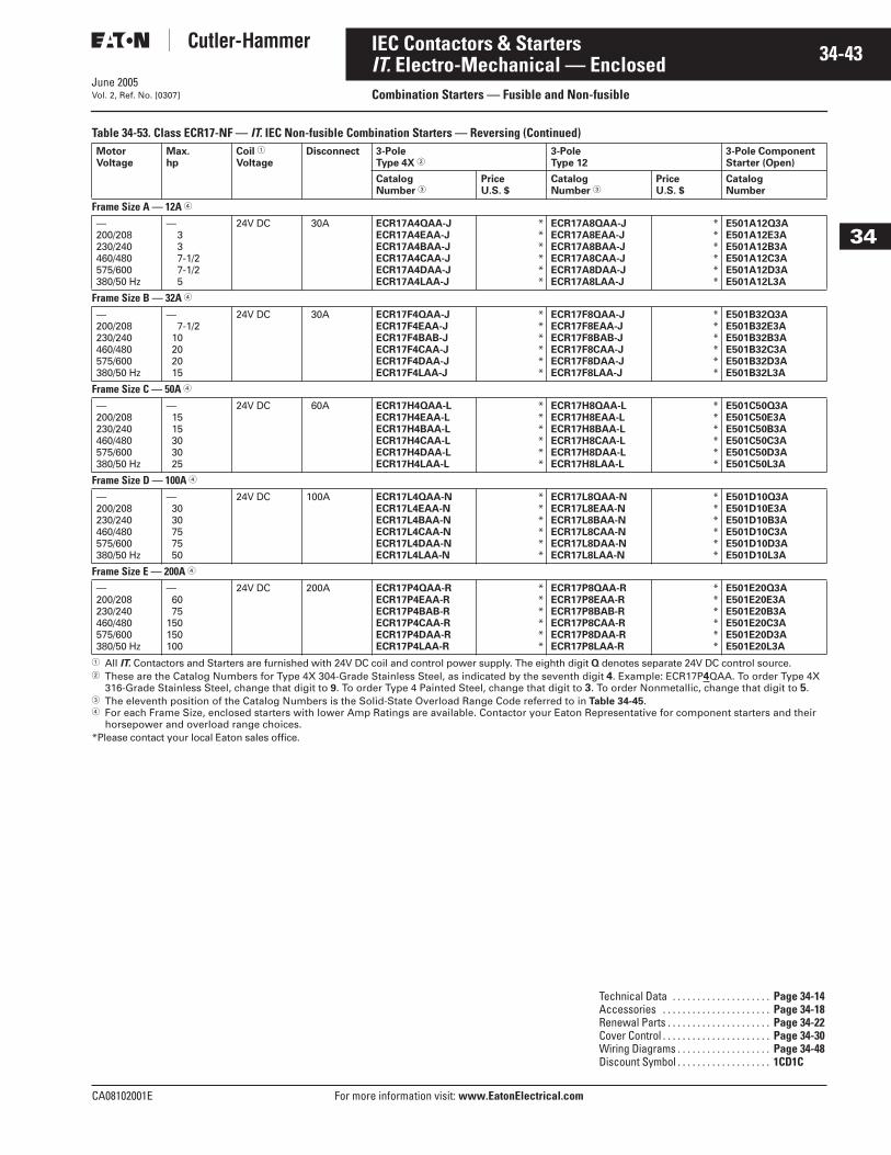
June 2005
CA08102001E For more information visit: www.EatonElectrical.com
34-43IEC Contactors & Starters
34
IT. Electro-Mechanical — EnclosedCombination Starters — Fusible and Non-fusibleVol. 2, Ref. No. [0307]
Table 34-53. Class ECR17-NF — IT. IEC Non-fusible Combination Starters — Reversing (Continued)
� All IT. Contactors and Starters are furnished with 24V DC coil and control power supply. The eighth digit Q denotes separate 24V DC control source.� These are the Catalog Numbers for Type 4X 304-Grade Stainless Steel, as indicated by the seventh digit 4. Example: ECR17P4QAA. To order Type 4X
316-Grade Stainless Steel, change that digit to 9. To order Type 4 Painted Steel, change that digit to 3. To order Nonmetallic, change that digit to 5.� The eleventh position of the Catalog Numbers is the Solid-State Overload Range Code referred to in Table 34-45.� For each Frame Size, enclosed starters with lower Amp Ratings are available. Contactor your Eaton Representative for component starters and their
horsepower and overload range choices.*Please contact your local Eaton sales office.
MotorVoltage
Max.hp
Coil �
VoltageDisconnect 3-Pole
Type 4X �3-PoleType 12
3-Pole ComponentStarter (Open)
Catalog Number �
PriceU.S. $
Catalog Number �
PriceU.S. $
CatalogNumber
Frame Size A — 12A �
—200/208230/240460/480575/600380/50 Hz
—337-1/27-1/25
24V DC 30A ECR17A4QAA-JECR17A4EAA-JECR17A4BAA-JECR17A4CAA-JECR17A4DAA-JECR17A4LAA-J
******
ECR17A8QAA-JECR17A8EAA-JECR17A8BAA-JECR17A8CAA-JECR17A8DAA-JECR17A8LAA-J
******
E501A12Q3AE501A12E3AE501A12B3AE501A12C3AE501A12D3AE501A12L3A
Frame Size B — 32A �
—200/208230/240460/480575/600380/50 Hz
—7-1/2
10202015
24V DC 30A ECR17F4QAA-JECR17F4EAA-JECR17F4BAB-JECR17F4CAA-JECR17F4DAA-JECR17F4LAA-J
******
ECR17F8QAA-JECR17F8EAA-JECR17F8BAB-JECR17F8CAA-JECR17F8DAA-JECR17F8LAA-J
******
E501B32Q3AE501B32E3AE501B32B3AE501B32C3AE501B32D3AE501B32L3A
Frame Size C — 50A �
—200/208230/240460/480575/600380/50 Hz
—1515303025
24V DC 60A ECR17H4QAA-LECR17H4EAA-LECR17H4BAA-LECR17H4CAA-LECR17H4DAA-LECR17H4LAA-L
******
ECR17H8QAA-LECR17H8EAA-LECR17H8BAA-LECR17H8CAA-LECR17H8DAA-LECR17H8LAA-L
******
E501C50Q3AE501C50E3AE501C50B3AE501C50C3AE501C50D3AE501C50L3A
Frame Size D — 100A �
—200/208230/240460/480575/600380/50 Hz
—3030757550
24V DC 100A ECR17L4QAA-NECR17L4EAA-NECR17L4BAA-NECR17L4CAA-NECR17L4DAA-NECR17L4LAA-N
******
ECR17L8QAA-NECR17L8EAA-NECR17L8BAA-NECR17L8CAA-NECR17L8DAA-NECR17L8LAA-N
******
E501D10Q3AE501D10E3AE501D10B3AE501D10C3AE501D10D3AE501D10L3A
Frame Size E — 200A �
—200/208230/240460/480575/600380/50 Hz
—6075
150150100
24V DC 200A ECR17P4QAA-RECR17P4EAA-RECR17P4BAB-RECR17P4CAA-RECR17P4DAA-RECR17P4LAA-R
******
ECR17P8QAA-RECR17P8EAA-RECR17P8BAB-RECR17P8CAA-RECR17P8DAA-RECR17P8LAA-R
******
E501E20Q3AE501E20E3AE501E20B3AE501E20C3AE501E20D3AE501E20L3A
Technical Data . . . . . . . . . . . . . . . . . . . . Page 34-14Accessories . . . . . . . . . . . . . . . . . . . . . . Page 34-18Renewal Parts . . . . . . . . . . . . . . . . . . . . . Page 34-22Cover Control . . . . . . . . . . . . . . . . . . . . . . Page 34-30Wiring Diagrams . . . . . . . . . . . . . . . . . . . Page 34-48Discount Symbol . . . . . . . . . . . . . . . . . . . 1CD1C
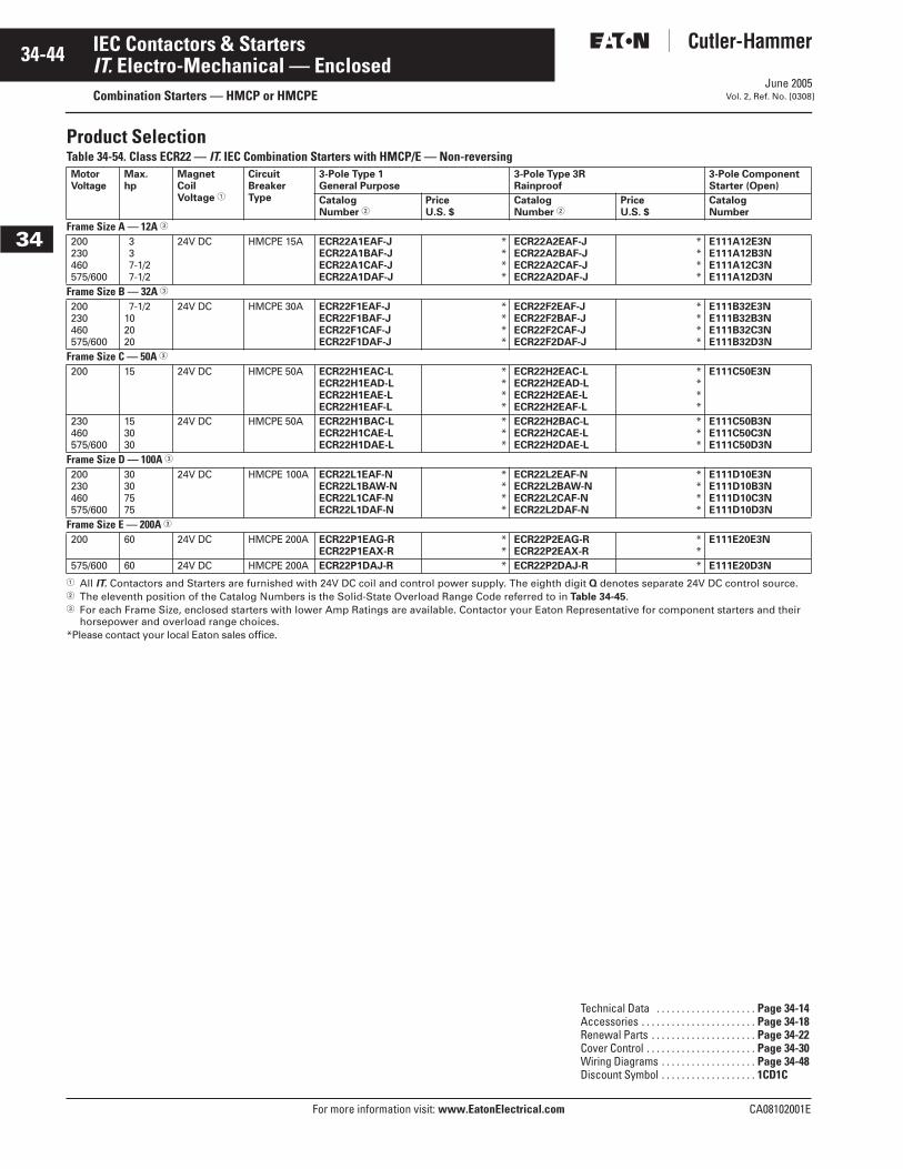
June 2005
34-44
For more information visit: www.EatonElectrical.com CA08102001E
IEC Contactors & Starters
34
IT. Electro-Mechanical — EnclosedCombination Starters — HMCP or HMCPE Vol. 2, Ref. No. [0308]
Product SelectionTable 34-54. Class ECR22 — IT. IEC Combination Starters with HMCP/E — Non-reversing
� All IT. Contactors and Starters are furnished with 24V DC coil and control power supply. The eighth digit Q denotes separate 24V DC control source.� The eleventh position of the Catalog Numbers is the Solid-State Overload Range Code referred to in Table 34-45.� For each Frame Size, enclosed starters with lower Amp Ratings are available. Contactor your Eaton Representative for component starters and their
horsepower and overload range choices. *Please contact your local Eaton sales office.
MotorVoltage
Max. hp
MagnetCoilVoltage �
CircuitBreakerType
3-Pole Type 1General Purpose
3-Pole Type 3RRainproof
3-Pole ComponentStarter (Open)
CatalogNumber �
PriceU.S. $
CatalogNumber �
PriceU.S. $
CatalogNumber
Frame Size A — 12A �
200230460575/600
337-1/27-1/2
24V DC HMCPE 15A ECR22A1EAF-JECR22A1BAF-JECR22A1CAF-JECR22A1DAF-J
****
ECR22A2EAF-JECR22A2BAF-JECR22A2CAF-JECR22A2DAF-J
****
E111A12E3NE111A12B3NE111A12C3NE111A12D3N
Frame Size B — 32A �
200230460575/600
7-1/2102020
24V DC HMCPE 30A ECR22F1EAF-JECR22F1BAF-JECR22F1CAF-JECR22F1DAF-J
****
ECR22F2EAF-JECR22F2BAF-JECR22F2CAF-JECR22F2DAF-J
****
E111B32E3NE111B32B3NE111B32C3NE111B32D3N
Frame Size C — 50A �
200 15 24V DC HMCPE 50A ECR22H1EAC-LECR22H1EAD-LECR22H1EAE-LECR22H1EAF-L
****
ECR22H2EAC-LECR22H2EAD-LECR22H2EAE-LECR22H2EAF-L
****
E111C50E3N
230460575/600
153030
24V DC HMCPE 50A ECR22H1BAC-LECR22H1CAE-LECR22H1DAE-L
***
ECR22H2BAC-LECR22H2CAE-LECR22H2DAE-L
***
E111C50B3NE111C50C3NE111C50D3N
Frame Size D — 100A �
200230460575/600
30307575
24V DC HMCPE 100A ECR22L1EAF-NECR22L1BAW-NECR22L1CAF-NECR22L1DAF-N
****
ECR22L2EAF-NECR22L2BAW-NECR22L2CAF-NECR22L2DAF-N
****
E111D10E3NE111D10B3NE111D10C3NE111D10D3N
Frame Size E — 200A �
200 60 24V DC HMCPE 200A ECR22P1EAG-RECR22P1EAX-R
**
ECR22P2EAG-RECR22P2EAX-R
**
E111E20E3N
575/600 60 24V DC HMCPE 200A ECR22P1DAJ-R * ECR22P2DAJ-R * E111E20D3N
Technical Data . . . . . . . . . . . . . . . . . . . . Page 34-14Accessories . . . . . . . . . . . . . . . . . . . . . . . Page 34-18Renewal Parts . . . . . . . . . . . . . . . . . . . . . Page 34-22Cover Control . . . . . . . . . . . . . . . . . . . . . . Page 34-30Wiring Diagrams . . . . . . . . . . . . . . . . . . . Page 34-48Discount Symbol . . . . . . . . . . . . . . . . . . . 1CD1C
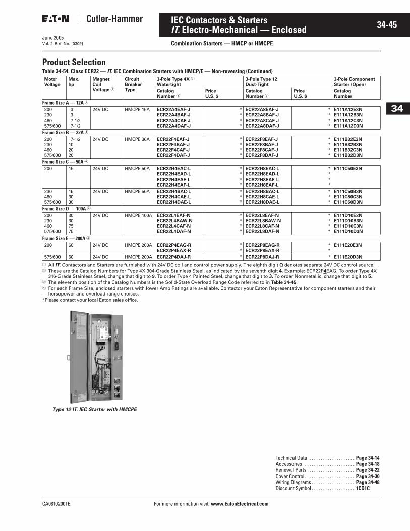
June 2005
CA08102001E For more information visit: www.EatonElectrical.com
34-45IEC Contactors & Starters
34
IT. Electro-Mechanical — EnclosedCombination Starters — HMCP or HMCPEVol. 2, Ref. No. [0309]
Product SelectionTable 34-54. Class ECR22 — IT. IEC Combination Starters with HMCP/E — Non-reversing (Continued)
� All IT. Contactors and Starters are furnished with 24V DC coil and control power supply. The eighth digit Q denotes separate 24V DC control source.� These are the Catalog Numbers for Type 4X 304-Grade Stainless Steel, as indicated by the seventh digit 4. Example: ECR22P4EAG. To order Type 4X
316-Grade Stainless Steel, change that digit to 9. To order Type 4 Painted Steel, change that digit to 3. To order Nonmetallic, change that digit to 5.� The eleventh position of the Catalog Numbers is the Solid-State Overload Range Code referred to in Table 34-45.� For each Frame Size, enclosed starters with lower Amp Ratings are available. Contactor your Eaton Representative for component starters and their
horsepower and overload range choices. *Please contact your local Eaton sales office.
Type 12 IT. IEC Starter with HMCPE
MotorVoltage
Max. hp
MagnetCoilVoltage �
CircuitBreakerType
3-Pole Type 4X �
Watertight3-Pole Type 12Dust-Tight
3-Pole ComponentStarter (Open)
CatalogNumber �
PriceU.S. $
CatalogNumber �
PriceU.S. $
CatalogNumber
Frame Size A — 12A �
200230460575/600
337-1/27-1/2
24V DC HMCPE 15A ECR22A4EAF-JECR22A4BAF-JECR22A4CAF-JECR22A4DAF-J
****
ECR22A8EAF-JECR22A8BAF-JECR22A8CAF-JECR22A8DAF-J
****
E111A12E3NE111A12B3NE111A12C3NE111A12D3N
Frame Size B — 32A �
200230460575/600
7-1/2102020
24V DC HMCPE 30A ECR22F4EAF-JECR22F4BAF-JECR22F4CAF-JECR22F4DAF-J
****
ECR22F8EAF-JECR22F8BAF-JECR22F8CAF-JECR22F8DAF-J
****
E111B32E3NE111B32B3NE111B32C3NE111B32D3N
Frame Size C — 50A �
200 15 24V DC HMCPE 50A ECR22H4EAC-LECR22H4EAD-LECR22H4EAE-LECR22H4EAF-L
****
ECR22H8EAC-LECR22H8EAD-LECR22H8EAE-LECR22H8EAF-L
****
E111C50E3N
230460575/600
153030
24V DC HMCPE 50A ECR22H4BAC-LECR22H4CAE-LECR22H4DAE-L
***
ECR22H8BAC-LECR22H8CAE-LECR22H8DAE-L
***
E111C50B3NE111C50C3NE111C50D3N
Frame Size D — 100A �
200230460575/600
30307575
24V DC HMCPE 100A ECR22L4EAF-NECR22L4BAW-NECR22L4CAF-NECR22L4DAF-N
****
ECR22L8EAF-NECR22L8BAW-NECR22L8CAF-NECR22L8DAF-N
****
E111D10E3NE111D10B3NE111D10C3NE111D10D3N
Frame Size E — 200A �
200 60 24V DC HMCPE 200A ECR22P4EAG-RECR22P4EAX-R
**
ECR22P8EAG-RECR22P8EAX-R
**
E111E20E3N
575/600 60 24V DC HMCPE 200A ECR22P4DAJ-R * ECR22P8DAJ-R * E111E20D3N
Technical Data . . . . . . . . . . . . . . . . . . . . Page 34-14Accessories . . . . . . . . . . . . . . . . . . . . . . Page 34-18Renewal Parts . . . . . . . . . . . . . . . . . . . . . Page 34-22Cover Control . . . . . . . . . . . . . . . . . . . . . . Page 34-30Wiring Diagrams . . . . . . . . . . . . . . . . . . . Page 34-48Discount Symbol . . . . . . . . . . . . . . . . . . . 1CD1C
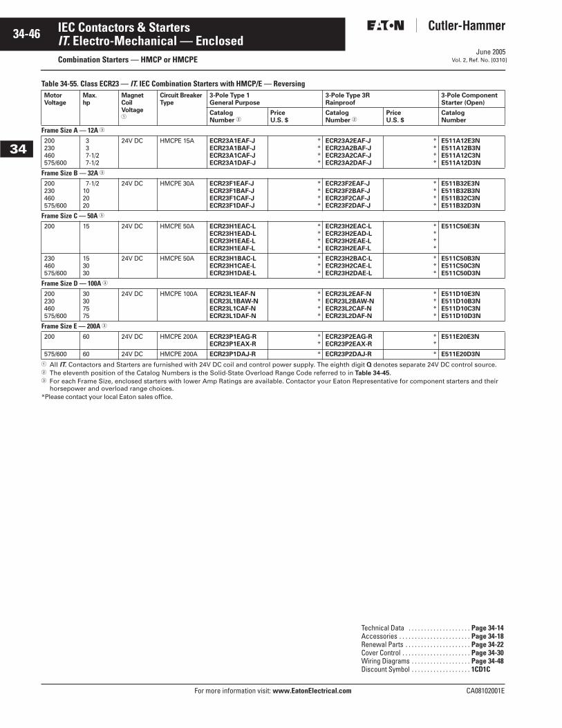
June 2005
34-46
For more information visit: www.EatonElectrical.com CA08102001E
IEC Contactors & Starters
34
IT. Electro-Mechanical — EnclosedCombination Starters — HMCP or HMCPE Vol. 2, Ref. No. [0310]
Table 34-55. Class ECR23 — IT. IEC Combination Starters with HMCP/E — Reversing
� All IT. Contactors and Starters are furnished with 24V DC coil and control power supply. The eighth digit Q denotes separate 24V DC control source. � The eleventh position of the Catalog Numbers is the Solid-State Overload Range Code referred to in Table 34-45.� For each Frame Size, enclosed starters with lower Amp Ratings are available. Contactor your Eaton Representative for component starters and their
horsepower and overload range choices.*Please contact your local Eaton sales office.
MotorVoltage
Max. hp
MagnetCoilVoltage�
Circuit BreakerType
3-Pole Type 1 General Purpose
3-Pole Type 3R Rainproof
3-Pole ComponentStarter (Open)
CatalogNumber �
PriceU.S. $
CatalogNumber �
PriceU.S. $
CatalogNumber
Frame Size A — 12A �
200230460575/600
337-1/27-1/2
24V DC HMCPE 15A ECR23A1EAF-JECR23A1BAF-JECR23A1CAF-JECR23A1DAF-J
****
ECR23A2EAF-JECR23A2BAF-JECR23A2CAF-JECR23A2DAF-J
****
E511A12E3NE511A12B3NE511A12C3NE511A12D3N
Frame Size B — 32A �
200230460575/600
7-1/2102020
24V DC HMCPE 30A ECR23F1EAF-JECR23F1BAF-JECR23F1CAF-JECR23F1DAF-J
****
ECR23F2EAF-JECR23F2BAF-JECR23F2CAF-JECR23F2DAF-J
****
E511B32E3NE511B32B3NE511B32C3NE511B32D3N
Frame Size C — 50A �
200 15 24V DC HMCPE 50A ECR23H1EAC-LECR23H1EAD-LECR23H1EAE-LECR23H1EAF-L
****
ECR23H2EAC-LECR23H2EAD-LECR23H2EAE-LECR23H2EAF-L
****
E511C50E3N
230460575/600
153030
24V DC HMCPE 50A ECR23H1BAC-LECR23H1CAE-LECR23H1DAE-L
***
ECR23H2BAC-LECR23H2CAE-LECR23H2DAE-L
***
E511C50B3NE511C50C3NE511C50D3N
Frame Size D — 100A �
200230460575/600
30307575
24V DC HMCPE 100A ECR23L1EAF-NECR23L1BAW-NECR23L1CAF-NECR23L1DAF-N
****
ECR23L2EAF-NECR23L2BAW-NECR23L2CAF-NECR23L2DAF-N
****
E511D10E3NE511D10B3NE511D10C3NE511D10D3N
Frame Size E — 200A �
200 60 24V DC HMCPE 200A ECR23P1EAG-RECR23P1EAX-R
**
ECR23P2EAG-RECR23P2EAX-R
**
E511E20E3N
575/600 60 24V DC HMCPE 200A ECR23P1DAJ-R * ECR23P2DAJ-R * E511E20D3N
Technical Data . . . . . . . . . . . . . . . . . . . . Page 34-14Accessories . . . . . . . . . . . . . . . . . . . . . . . Page 34-18Renewal Parts . . . . . . . . . . . . . . . . . . . . . Page 34-22Cover Control . . . . . . . . . . . . . . . . . . . . . . Page 34-30Wiring Diagrams . . . . . . . . . . . . . . . . . . . Page 34-48Discount Symbol . . . . . . . . . . . . . . . . . . . 1CD1C
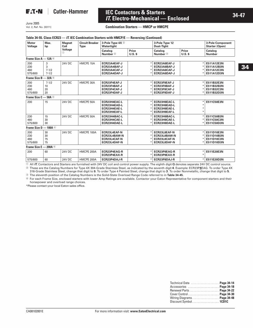
June 2005
CA08102001E For more information visit: www.EatonElectrical.com
34-47IEC Contactors & Starters
34
IT. Electro-Mechanical — EnclosedCombination Starters — HMCP or HMCPEVol. 2, Ref. No. [0311]
Table 34-55. Class ECR23 — IT. IEC Combination Starters with HMCP/E — Reversing (Continued)
� All IT. Contactors and Starters are furnished with 24V DC coil and control power supply. The eighth digit Q denotes separate 24V DC control source. � These are the Catalog Numbers for Type 4X 304-Grade Stainless Steel, as indicated by the seventh digit 4. Example: ECR23P4EAG. To order Type 4X
316-Grade Stainless Steel, change that digit to 9. To order Type 4 Painted Steel, change that digit to 3. To order Nonmetallic, change that digit to 5.� The eleventh position of the Catalog Numbers is the Solid-State Overload Range Code referred to in Table 34-45.� For each Frame Size, enclosed starters with lower Amp Ratings are available. Contactor your Eaton Representative for component starters and their
horsepower and overload range choices.*Please contact your local Eaton sales office.
MotorVoltage
Max. hp
MagnetCoilVoltage�
Circuit BreakerType
3-Pole Type 4X �
Watertight3-Pole Type 12 Dust-Tight
3-Pole ComponentStarter (Open)
CatalogNumber �
PriceU.S. $
CatalogNumber �
PriceU.S. $
CatalogNumber
Frame Size A — 12A �
200230460575/600
337-1/27-1/2
24V DC HMCPE 15A ECR23A4EAF-JECR23A4BAF-JECR23A4CAF-JECR23A4DAF-J
****
ECR23A8EAF-JECR23A8BAF-JECR23A8CAF-JECR23A8DAF-J
****
E511A12E3NE511A12B3NE511A12C3NE511A12D3N
Frame Size B — 32A �
200230460575/600
7-1/2102020
24V DC HMCPE 30A ECR23F4EAF-JECR23F4BAF-JECR23F4CAF-JECR23F4DAF-J
****
ECR23F8EAF-JECR23F8BAF-JECR23F8CAF-JECR23F8DAF-J
****
E511B32E3NE511B32B3NE511B32C3NE511B32D3N
Frame Size C — 50A �
200 15 24V DC HMCPE 50A ECR23H4EAC-LECR23H4EAD-LECR23H4EAE-LECR23H4EAF-L
****
ECR23H8EAC-LECR23H8EAD-LECR23H8EAE-LECR23H8EAF-L
****
E511C50E3N
230460575/600
153030
24V DC HMCPE 50A ECR23H4BAC-LECR23H4CAE-LECR23H4DAE-L
***
ECR23H8BAC-LECR23H8CAE-LECR23H8DAE-L
***
E511C50B3NE511C50C3NE511C50D3N
Frame Size D — 100A �
200230460575/600
30307575
24V DC HMCPE 100A ECR23L4EAF-NECR23L4BAW-NECR23L4CAF-NECR23L4DAF-N
****
ECR23L8EAF-NECR23L8BAW-NECR23L8CAF-NECR23L8DAF-N
****
E511D10E3NE511D10B3NE511D10C3NE511D10D3N
Frame Size E — 200A �
200 60 24V DC HMCPE 200A ECR23P4EAG-RECR23P4EAX-R
**
ECR23P8EAG-RECR23P8EAX-R
**
E511E20E3N
575/600 60 24V DC HMCPE 200A ECR23P4DAJ-R * ECR23P8DAJ-R * E511E20D3N
Technical Data . . . . . . . . . . . . . . . . . . . . Page 34-14Accessories . . . . . . . . . . . . . . . . . . . . . . Page 34-18Renewal Parts . . . . . . . . . . . . . . . . . . . . . Page 34-22Cover Control . . . . . . . . . . . . . . . . . . . . . . Page 34-30Wiring Diagrams . . . . . . . . . . . . . . . . . . . Page 34-48Discount Symbol . . . . . . . . . . . . . . . . . . . 1CD1C
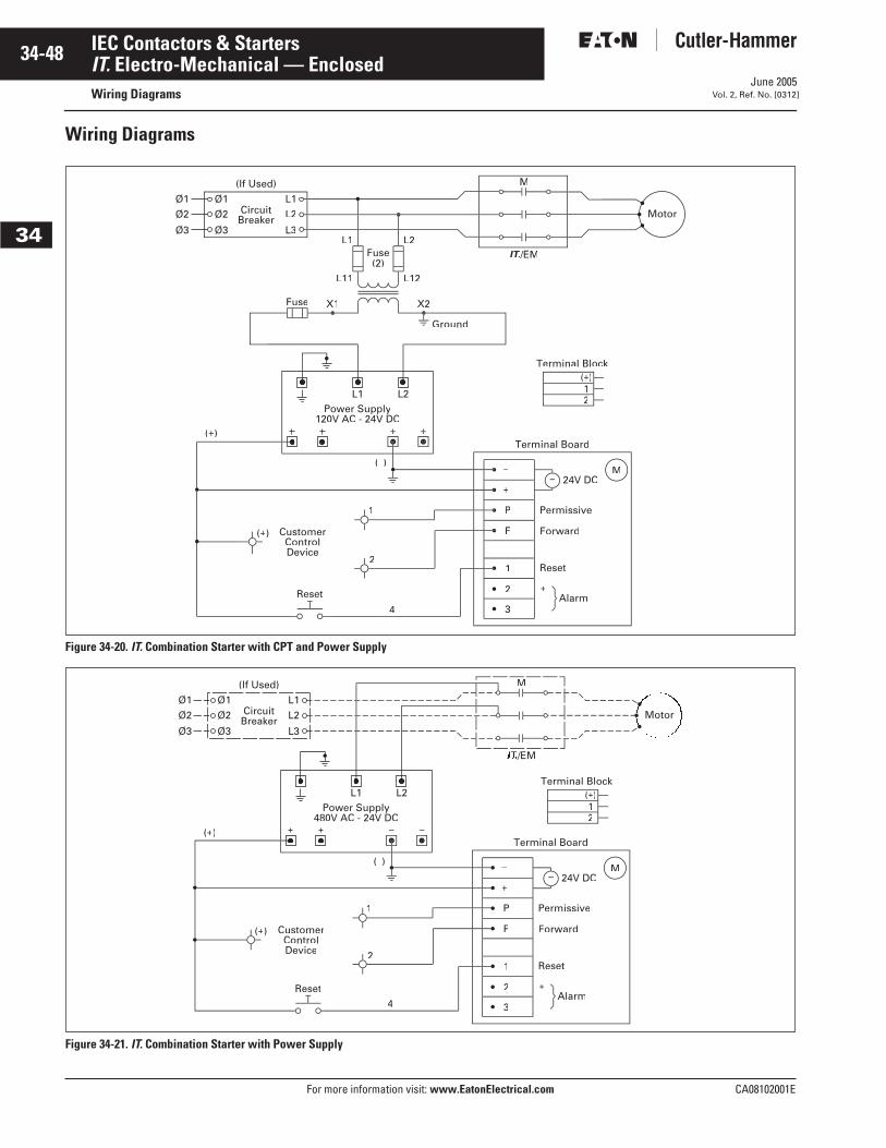
June 2005
34-48
For more information visit: www.EatonElectrical.com CA08102001E
IEC Contactors & Starters
34
IT. Electro-Mechanical — EnclosedWiring Diagrams Vol. 2, Ref. No. [0312]
Wiring Diagrams
Figure 34-20. IT. Combination Starter with CPT and Power Supply
Figure 34-21. IT. Combination Starter with Power Supply
CustomerControlDevice
(+)
2
1
(+
–
P
+
–
+Alarm
Reset
Forward
Permissive
24V DC
Terminal Board
F
1
=M
2
3
(+)
2
Reset
4
Fuse
Ground
Fuse(2)
X2
L1
L11
L2
L12
X1
Terminal Block
Motor
M
L1
L2
L3
Ø1
Ø2
Ø3
Ø1
Ø2
Ø3
(If Used)
CircuitBreaker
IT./EM
(–)
L1Power Supply
120V AC - 24V DC
L2
Reset4
(–) –
CustomerControlDevice 2
1 P
(+)
(+
(+)
+
–
+Alarm
Reset
Forward
Permissive
24V DC
Terminal Board
F
1
=M
2
3
12
Terminal Block
Motor
M
L1
L1Power Supply
480V AC - 24V DC
L2
L2
L3
Ø1
Ø2
Ø3
Ø1
Ø2
Ø3
(If Used)
CircuitBreaker
/EM
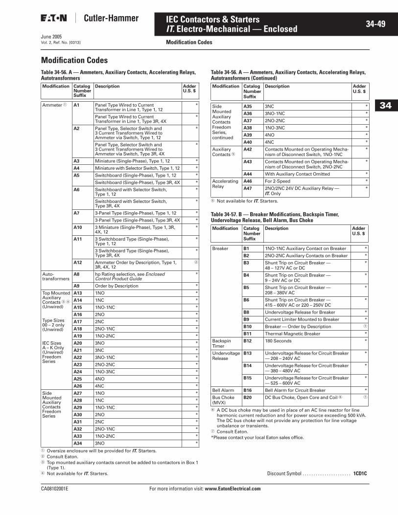
June 2005
CA08102001E For more information visit: www.EatonElectrical.com
34-49IEC Contactors & Starters
34
IT. Electro-Mechanical — EnclosedModification CodesVol. 2, Ref. No. [0313]
Modification Codes Table 34-56. A — Ammeters, Auxiliary Contacts, Accelerating Relays, Autotransformers
� Oversize enclosure will be provided for IT. Starters.� Consult Eaton.� Top mounted auxiliary contacts cannot be added to contactors in Box 1
(Type 1).� Not available for IT. Starters.
Table 34-56. A — Ammeters, Auxiliary Contacts, Accelerating Relays, Autotransformers (Continued)
� Not available for IT. Starters.
Table 34-57. B — Breaker Modifications, Backspin Timer,Undervoltage Release, Bell Alarm, Bus Choke
� A DC bus choke may be used in place of an AC line reactor for line harmonic current reduction and for power source exceeding 500 kVA. The DC bus choke will not provide any protection for line voltage unbalance or transients.
� Consult Eaton.*Please contact your local Eaton sales office.
Modification CatalogNumberSuffix
Description AdderU.S. $
Ammeter � A1 Panel Type Wired to Current Transformer in Line 1, Type 1, 12
*
Panel Type Wired to Current Transformer in Line 1, Type 3R, 4X
*
A2 Panel Type, Selector Switch and 3 Current Transformers Wired to Ammeter via Switch, Type 1, 12
*
Panel Type, Selector Switch and 3 Current Transformers Wired to Ammeter via Switch, Type 3R, 4X
*
A3 Miniature (Single-Phase), Type 1, 12 *
A4 Miniature with Selector Switch, Type 1, 12 *
A5 Switchboard (Single-Phase), Type 1, 12 *
Switchboard (Single-Phase), Type 3R, 4X *
A6 Switchboard with Selector Switch, Type 1, 12
*
Switchboard with Selector Switch, Type 3R, 4X
*
A7 3-Panel Type (Single-Phase), Type 1, 12 *
3-Panel Type (Single-Phase), Type 3R, 4X *
A10 3 Miniature (Single-Phase), Type 1, 3R, 4X, 12
*
A11 3 Switchboard Type (Single-Phase), Type 1, 12
*
3 Switchboard Type (Single-Phase),Type 3R, 4X
*
A12 Ammeter Order by Description, Type 1, 3R, 4X, 12
�
Auto-transformers
A8 hp Rating selection, see Enclosed Control Product Guide
*
A9 Order by Description *
Top Mounted AuxiliaryContacts � �(Unwired)
Type Sizes 00 – 2 only(Unwired)
IEC SizesA – K Only(Unwired)Freedom Series
A13 1NO *
A14 1NC *
A15 1NO-1NC *
A16 2NO *
A17 2NC *
A18 2NO-1NC *
A19 1NO-2NC *
A20 3NO *
A21 3NC *
A22 3NO-1NC *
A23 2NO-2NC *
A24 1NO-3NC *
A25 4NO *
A26 4NC *
Side Mounted Auxiliary Contacts Freedom Series
A27 1NO *
A28 1NC *
A29 1NO-1NC *
A30 2NO *
A31 2NC *
A32 2NO-1NC *
A33 1NO-2NC *
A34 3NO *
Modification CatalogNumberSuffix
Description AdderU.S. $
Side Mounted Auxiliary Contacts Freedom Series, continued
A35 3NC *
A36 3NO-1NC *
A37 2NO-2NC *
A38 1NO-3NC *
A39 4NO *
A40 4NC *
Auxiliary Contacts �
A42 Contacts Mounted on Operating Mecha-nism of Disconnect Switch, 1NO-1NC
*
A43 Contacts Mounted on Operating Mecha-nism of Disconnect Switch, 2NO-2NC
*
A44 With Auxiliary Contact Omitted *
Accelerating Relay
A46 For 2-Speed *
A47 2NO/2NC 24V DC Auxiliary Relay — IT. Only
*
Modification CatalogNumberSuffix
Description AdderU.S. $
Breaker B1 1NO-1NC Auxiliary Contact on Breaker *
B2 2NO-2NC Auxiliary Contacts on Breaker *
B3 Shunt Trip on Circuit Breaker — 48 – 127V AC or DC
*
B4 Shunt Trip on Circuit Breaker —9 – 24V AC or DC
*
B5 Shunt Trip on Circuit Breaker —208 – 380V AC
*
B6 Shunt Trip on Circuit Breaker —415 – 600V AC or 220 – 250V DC
*
B8 Undervoltage Release for Breaker *
B9 Current Limiter Mounted to Breaker *
B10 Breaker — Order by Description �
B11 Thermal Magnetic Breaker *
Backspin Timer
B12 180 Seconds *
Undervoltage Release
B13 Undervoltage Release for Circuit Breaker — 208 – 240V AC
*
B14 Undervoltage Release for Circuit Breaker — 380 – 480V AC
*
B15 Undervoltage Release for Circuit Breaker — 525 – 600V AC
*
Bell Alarm B16 Bell Alarm for Circuit Breaker *
Bus Choke(MVX)
B20 DC Bus Choke, Open Core and Coil � �
Discount Symbol . . . . . . . . . . . . . . . . . . . . . . 1CD1C
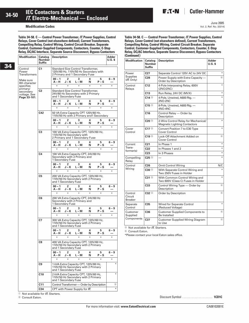
June 2005
34-50
For more information visit: www.EatonElectrical.com CA08102001E
IEC Contactors & Starters
34
IT. Electro-Mechanical — EnclosedModification Codes Vol. 2, Ref. No. [0314]
Table 34-58. C — Control Power Transformer, IT. Power Supplies, Control Relays, Cover Control (not elsewhere defined), Current Transformers, Compelling Relay, Control Wiring, Control Circuit Breaker, Separate Control, Customer-Supplied Components, Contactors, Counter, E-Stop Relay, DC/AC Interface, Separate Source Disconnect, Bypass Contactors
� Not available for IT. Starters.� Consult Eaton.
Table 34-58. C — Control Power Transformer, IT. Power Supplies, Control Relays, Cover Control (not elsewhere defined), Current Transformers, Compelling Relay, Control Wiring, Control Circuit Breaker, Separate Control, Customer-Supplied Components, Contactors, Counter, E-Stop Relay, DC/AC Interface, Separate Source Disconnect, Bypass Contactors (Continued)
� Not available for IT. Starters.� Consult Eaton.*Please contact your local Eaton sales office.
Modification CatalogNumberSuffix
Description AdderU.S. $
Control PowerTransformers
Make sure 8th character specifies primary/secondaryvoltage. SeePage 33-101.
C1 Standard Size Control Transformer, 120V/60 Hz, 110V/50 Hz Secondary with 2 Primary and 1 Secondary Fuse
00 – 1A – H
2J – K
3L – M
4N
5P – S
6 – 9—
* * * * * *
C2 Standard Size Control Transformer,24V/60 Hz Secondary with 2 Primary and 1 Secondary Fuse
00 – 1A – H
2J – K
3L – M
4N
5P – S
6 – 9—
* * * * * *
C42 50 VA Extra Capacity CPT 120V/60 Hz, 110V/50 Hz with 2 Primary and1 Secondary
00 – 1A – H
2J – K
3L – M
4N
5P – S
6 – 9—
* * * * * *
C3 100 VA Extra Capacity CPT, 120V/60 Hz, 110V/50 Hz Secondary with 2 Primary and 1 Secondary Fuse
00 – 1A – H
2J – K
3L – M
4N
5P – S
6 – 9—
* * * * * *
C4 100 VA Extra Capacity CPT, 24V/60 Hz Secondary with 2 Primary and 1 Secondary Fuse
00 – 1A – H
2J – K
3L – M
4N
5P – S
6 – 9—
* * * * * *
C5 200 VA Extra Capacity CPT, 120V/60 Hz, 110V/50 Hz Secondary with 2 Primary and 1 Secondary Fuse
00 – 1A – H
2J – K
3L – M
4N
5P – S
6 – 9—
* * * * * *
C6 200 VA Extra Capacity CPT, 24V/60 Hz Secondary with 2 Primary and 1 Secondary Fuse
00 – 1A – H
2J – K
3L – M
4N
5P – S
6 – 9—
* * * * * *
C7 300 VA Extra Capacity CPT, 120V/60 Hz, 110V/50 Hz Secondary with 2 Primary and 1 Secondary Fuse
00 – 1A – H
2J – K
3L – M
4N
5P – S
6 – 9—
* * * * * *
C8 400 VA Extra Capacity CPT, 120V/60 Hz, 110V/50 Hz Secondary with 2 Primary and 1 Secondary Fuse
00 – 1A – H
2J – K
3L – M
4N
5P – S
6 – 9—
* * * * * *
C9 1 kVA Extra Capacity CPT, 120V/60 Hz, 110V/50 Hz Secondary with 2 Primary and 1 Secondary Fuse
*
C10 2 kVA Extra Capacity CPT, 120V/60 Hz, 110V/50 Hz Secondary with 2 Primary and 1 Secondary Fuse
*
C11 Control Transformer — Order by Description �
C34 CPT with Power Supply for IT. *
Modification CatalogNumberSuffix
Description AdderU.S. $
Power Supplies (IT. Only)
C27 Separate Control 120V AC to 24V DC *
C28 Power Supply with Extra Capacity — Order by Description
�
Control Relays
C12 4-Pole Interposing Relay, 600V (2NO/2NC)
*
C13 Run Relay, 24V DC (MVX) *
C14 � 4-Pole, Unwired, A600 Rtg. — 2NO-2NC
*
C15 � 8-Pole, Unwired, A600 Rtg. — 4NO-4NC
*
C16 Control Relay — Order by Description
�
C20 � 2-Wire Control Relay for Mechanical/Magnetic Lighting Contactors
*
Cover Control
C17 � Convert Position 7 to E30 Type Cover Control
*
C19 � Lock-Off Attachment Added on Cover Control
�
Current Trans-former(s)
C21 In Phase 1 *
C22 In Phases 1 and 2 *
C23 In 3 Phases *
CompellingRelay
C25 � — *
ControlWiring
C26 Omit Control Wiring N/C
C30 � With Separate Control Wiring and Two 250V Fuses in Holder
*
C31 � With Common Control Wiring and Two 600V (Class C) Fuses in Holder
*
C33 Control Wiring Type — Order by Description
�
Control CircuitBreaker
C32 � Order by Description �
SeparateControl
C35 Wired for Separate Control (Reduced Voltage)
*
CustomerSuppliedComponents
C36 Customer Supplied Components to Be Installed
�
C37 Customer Supplied Wiring Diagram to Use
�
Discount Symbol . . . . . . . . . . . . . . . . . . . . . . 1CD1C
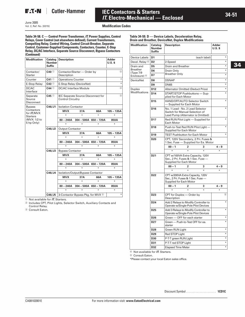
June 2005
CA08102001E For more information visit: www.EatonElectrical.com
34-51IEC Contactors & Starters
34
IT. Electro-Mechanical — EnclosedModification CodesVol. 2, Ref. No. [0315]
Table 34-58. C — Control Power Transformer, IT. Power Supplies, Control Relays, Cover Control (not elsewhere defined), Current Transformers, Compelling Relay, Control Wiring, Control Circuit Breaker, Separate Control, Customer-Supplied Components, Contactors, Counter, E-Stop Relay, DC/AC Interface, Separate Source Disconnect, Bypass Contactors (Continued)
� Not available for IT. Starters.� Includes CPT, Pilot Lights, Selector Switch, Auxiliary Contacts and
Control Relay.� Consult Eaton.
Table 34-59. D — Device Labels, Deceleration Relay, Drain and Breather, DeviceNet, Duplex Modifications
� Not available for IT. Starters.� Consult Eaton.*Please contact your local Eaton sales office.
Modification CatalogNumberSuffix
Description AdderU.S. $
Contactor/Starter
C40 � Contactor/Starter — Order by Description
�
Counter C41 � Operations Counter *
E-Stop Relay C43 � E-Stop Relay (DeviceNet) *
DC/AC Interface
C44 � DC/AC Interface Module �
SeparateSource Disconnect
C45 � IEC Separate Source Disconnect for Control Circuitry
�
Bypass Contactorsfor IT./MVXStarters (MVX: 1/2 to 5 hp Only)
C46/J1 Isolation Contactor
MVX 37A 66A 105 – 135A
* * * *
80 – 240A 304 – 500A 650 – 720A 850A
* * * *
C46/J2 Output Contactor
MVX 37A 66A 105 – 135A
* * * *
80 – 240A 304 – 500A 650 – 720A 850A
* * * *
C46/J3 Bypass Contactor
MVX 37A 66A 105 – 135A
* * * *
80 – 240A 304 – 500A 650 – 720A 850A
* * * *
C46/J4 Isolation/Output/Bypass Contactor
MVX 37A 66A 105 – 135A
* * * *
80 – 240A 304 – 500A 650 – 720A 850A
* * * *
C46/J5 3-Contactor Bypass Pkg. for MVX � *
Modification CatalogNumberSuffix
Description AdderU.S. $
Device Labels D1 (each label) *
Decel. Relay � D2 2-Speed *
Drain andBreather(Type 7/9 Enclosure) �
D5 Drain and Breather *
D6 Drain OnlyBreather Only
*
D7 *
DeviceNet D8 DSNAP *
D9 DN65 *
DuplexModifications
D12 Alternator Omitted (Deduct Price) *
D14 START/STOP Pushbuttons — Sup-plied for Each Motor
*
D15 HAND/OFF/AUTO Selector Switch — Supplied for Each Motor
*
D16 No. 1 Lead - No. 2 Lead Selector Switch for Manual Selection of Lead Pump (Alternator is Omitted)
*
D17 Red RUN Pilot Light — Supplied for Each Motor
*
D18 Push-to-Test Red RUN Pilot Light — Supplied for Each Motor
*
D19 TEST Pushbutton for Each Motor *
D20 CPT, 120V Secondary, 2 Pri. Fuses & 1 Sec. Fuse — Supplied for Ea. Motor
00 – 1 2 3 4 – 9
* * * *
D21 CPT w/100VA Extra Capacity, 120V Sec., 2 Pri. Fuses & 1 Sec. Fuse — Supplied for Each Motor
00 – 1 2 3 4 – 9
* * * *
D22 CPT w/200VA Extra Capacity, 120V Sec., 2 Pri. Fuses & 1 Sec. Fuse — Supplied for Each Motor
00 – 1 2 3 4 – 9
* * * *
D23 CPT for Duplex — Order by Description
�
D24 Add 2 Relays to Modify Controller to Operate w/Single-Pole Pilot Devices
*
D25 Add 3 Relays to Modify Controller to Operate w/Single-Pole Pilot Devices
*
D26 Green — OFF for each starter *
D27 Green — Push-to-Test OFF for ea. starter
*
D28 Green RUN Light *
D29 Red STOP Light *
D30 P-T-T green RUN Light *
D31 P-T-T red STOP Light *
D32 Elapsed Time Meter *
Discount Symbol . . . . . . . . . . . . . . . . . . . . . . 1CD1C
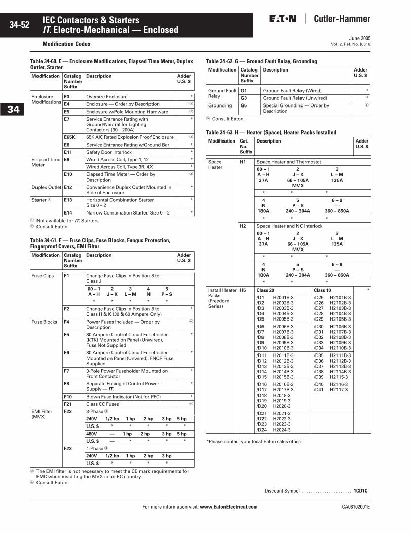
June 2005
34-52
For more information visit: www.EatonElectrical.com CA08102001E
IEC Contactors & Starters
34
IT. Electro-Mechanical — EnclosedModification Codes Vol. 2, Ref. No. [0316]
Table 34-60. E — Enclosure Modifications, Elapsed Time Meter, Duplex Outlet, Starter
� Not available for IT. Starters.� Consult Eaton.
Table 34-61. F — Fuse Clips, Fuse Blocks, Fungus Protection, Fingerproof Covers, EMI Filter
� The EMI filter is not necessary to meet the CE mark requirements for EMC when installing the MVX in an EC country.
� Consult Eaton.
Table 34-62. G — Ground Fault Relay, Grounding
� Consult Eaton.
Table 34-63. H — Heater (Space), Heater Packs Installed
*Please contact your local Eaton sales office.
Modification CatalogNumberSuffix
Description AdderU.S. $
EnclosureModifications
E3 Oversize Enclosure *
E4 Enclosure — Order by Description �
E5 Enclosure w/Pole Mounting Hardware �
E7 Service Entrance Rating with Ground/Neutral for Lighting Contactors (30 – 200A)
*
E65K 65K AIC Rated Explosion Proof Enclosure �
E8 Service Entrance Rating w/Ground Bar *
E11 Safety Door Interlock *
Elapsed Time Meter
E9 Wired Across Coil, Type 1, 12 *
Wired Across Coil, Type 3R, 4X *
E10 Elapsed Time Meter — Order by Description
�
Duplex Outlet E12 Convenience Duplex Outlet Mounted in Side of Enclosure
*
Starter � E13 Horizontal Combination Starter, Size 0 – 2
*
E14 Narrow Combination Starter, Size 0 – 2 *
Modification CatalogNumberSuffix
Description AdderU.S. $
Fuse Clips F1 Change Fuse Clips in Position 8 to Class J
00 – 1A – H
2J – K
3L – M
4N
5P – S
* * * * *
F2 Change Fuse Clips in Position 8 to Class H & K (30 & 60 Ampere Only)
*
Fuse Blocks F4 Power Fuses Included — Order byDescription
�
F5 30 Ampere Control Circuit Fuseholder (KTK) Mounted on Panel (Unwired), Fuse Not Supplied
*
F6 30 Ampere Control Circuit Fuseholder Mounted on Panel (Unwired), FNQR Fuse Supplied
*
F7 3-Pole Power Fuseholder Mounted on Front Contactor
*
F8 Separate Fusing of Control Power Supply — IT.
*
F10 Blown Fuse Indicator (Not for PFC) *
F21 Class CC Fuses �
EMI Filter(MVX)
F22 3-Phase �
240V 1/2 hp 1 hp 2 hp 3 hp 5 hp
U.S. $ * * * * *
480V — 1 hp 2 hp 3 hp 5 hp
U.S. $ — * * * *
F23 1-Phase �
240V 1/2 hp 1 hp 2 hp 3 hp
U.S. $ * * * *
Modification CatalogNumberSuffix
Description AdderU.S. $
Ground Fault Relay
G1 Ground Fault Relay (Wired) *
G3 Ground Fault Relay (Unwired) *
Grounding G5 Special Grounding — Order by Description
�
Modification Cat.No.Suffix
Description AdderU.S. $
SpaceHeater
H1 Space Heater and Thermostat
00 – 1A – H37A
2J – K
66 – 105AMVX
3L – M135A
* * *
4N
180A
5P – S
240 – 304A
6 – 9—
360 – 850A
* * *
H2 Space Heater and NC Interlock
00 – 1A – H37A
2J – K
66 – 105AMVX
3L – M135A
* * *
4N
180A
5P – S
240 – 304A
6 – 9—
360 – 850A
* * *
Install HeaterPacks (FreedomSeries)
H5 Class 20 Class 10 *
/D1 H2001B-3/D2 H2002B-3/D3 H2003B-3/D4 H2004B-3/D5 H2005B-3
/D25 H2101B-3/D26 H2102B-3/D27 H2103B-3/D28 H2104B-3/D29 H2105B-3
/D6 H2006B-3/D7 H2007B-3/D8 H2008B-3/D9 H2009B-3/D10 H2010B-3
/D30 H2106B-3/D31 H2107B-3/D32 H2108B-3/D33 H2109B-3/D34 H2110B-3
/D11 H2011B-3/D12 H2012B-3/D13 H2013B-3/D14 H2014B-3/D15 H2015B-3
/D35 H2111B-3/D36 H2112B-3/D37 H2113B-3/D38 H2114B-3/D39 H2115-3
/D16 H2016B-3/D17 H2017B-3/D18 H2018-3/D19 H2019-3/D20 H2020-3
/D40 H2116-3/D41 H2117-3
/D21 H2021-3/D22 H2022-3/D23 H2023-3/D24 H2024-3
Discount Symbol . . . . . . . . . . . . . . . . . . . . . . 1CD1C
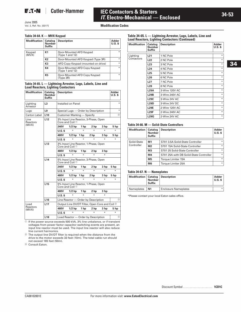
June 2005
CA08102001E For more information visit: www.EatonElectrical.com
34-53IEC Contactors & Starters
34
IT. Electro-Mechanical — EnclosedModification CodesVol. 2, Ref. No. [0317]
Table 34-64. K — MVX Keypad
Table 34-65. L — Lightning Arrestor, Lugs, Labels, Line and Load Reactors, Lighting Contactors
� If the power source exceeds 500 kVA, 3% line unbalance, or if transient voltages from power factor capacitor switching events are present, an input line reactor must be used. The input line reactor will also reduce line current harmonics.
� The output line DV/DT filter is required when the distance from the drive to the motor exceeds 33 feet (10m). The total cable run should not exceed 165 feet (50m).
� Consult Eaton.
Table 34-65. L — Lightning Arrestor, Lugs, Labels, Line and Load Reactors, Lighting Contactors (Continued)
Table 34-66. M — Solid-State Controllers
Table 34-67. N — Nameplates
*Please contact your local Eaton sales office.
Modification CatalogNumberSuffix
Description AdderU.S. $
Keypad(MVX)
K1 Door-Mounted AFD Keypad (Type 1 and 12)
*
K2 Door-Mounted AFD Keypad (Type 3R) *
K3 AFD Copy Keypad (mounted on drive) *
K4 Door-Mounted AFD Copy Keypad (Type 1 and 12)
*
K5 Door-Mounted AFD Copy Keypad (Type 3R)
*
Modification CatalogNumberSuffix
Description AdderU.S. $
Lighting Arrestor
L3 Installed on Panel *
Lugs L9 Special Lugs — Order by Description *
Carton Label L10 Customer Marking — Specify �
LineReactors(MVX)
L12 3% Input Line Reactor, 3-Phase, Open Core and Coil �
240V 1/2 hp 1 hp 2 hp 3 hp 5 hp
U.S. $ * * * * *
480V 1/2 hp 1 hp 2 hp 3 hp 5 hp
U.S. $ * * * * *
L13 3% Input Line Reactor, 1-Phase, Open Core and Coil �
480V 1/2 hp 1 hp 2 hp 3 hp
U.S. $ * * * *
L14 5% Input Line Reactor, 3-Phase, Open Core and Coil �
240V 1/2 hp 1 hp 2 hp 3 hp 5 hp
U.S. $ * * * * *
480V 1/2 hp 1 hp 2 hp 3 hp 5 hp
U.S. $ * * * * *
L15 5% Input Line Reactor, 1-Phase, Open Core and Coil �
480V 1/2 hp 1 hp 2 hp 3 hp
U.S. $ * * * *
L16 Line Reactor — Order by Description �
LoadReactors(MVX)
L17 Output Line DV/DT Filter, Open Core and Coil �
480V 1/2 hp 1 hp 2 hp 3 hp 5 hp
U.S. $ * * * * *
L18 Load Reactor — Order by Description �
Modification CatalogNumberSuffix
Description AdderU.S. $
Lighting Contactors
L21 1 NC Pole *
L22 2 NC Pole *
L23 3 NC Pole *
L24 4 NC Pole *
L25 5 NC Pole *
L26 6 NC Pole *
L27 7 NC Pole *
L28 8 NC Pole *
L29A 3-Wire 120V AC *
L29B 3-Wire 240V AC *
L29C 3-Wire 24V AC *
L29D 3-Wire 24V DC *
L29E 2-Wire 120V AC *
L29F 2-Wire 240V AC *
L29G 2-Wire 24V AC *
Modification CatalogNumberSuffix
Description AdderU.S. $
Solid-State Controller
M1 S701 3.5A Solid-State Controller *
M2 S701 15A Solid-State Controller *
M3 S701 25 Solid-State Controller *
M4 S701 25A with DB Solid-State Controller *
M5 Torque Limiter 15A *
M6 Torque Limiter 25A *
Modification CatalogNumberSuffix
Description AdderU.S. $
Nameplates N1 Enclosure Nameplates *
Discount Symbol . . . . . . . . . . . . . . . . . . . . . . 1CD1C
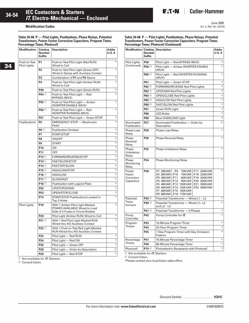
June 2005
34-54
For more information visit: www.EatonElectrical.com CA08102001E
IEC Contactors & Starters
34
IT. Electro-Mechanical — EnclosedModification Codes Vol. 2, Ref. No. [0318]
Table 34-68. P — Pilot Lights, Pushbuttons, Phase Relays, Potential Transformers, Power Factor Correction Capacitors, Program Timer, Percentage Timer, Photocell
� Not available for IT. Starters.� Consult Eaton.
Table 34-68. P — Pilot Lights, Pushbuttons, Phase Relays, Potential Transformers, Power Factor Correction Capacitors, Program Timer, Percentage Timer, Photocell (Continued)
� Not available for IT. Starters.� Consult Eaton.*Please contact your local Eaton sales office.
Modification CatalogNumberSuffix
Description AdderU.S. $
Push-to-TestPilot Lights
P1 Push-to-Test Pilot Light (Red RUN)Wired to Coil
*
P2 Push-to-Test Pilot Light (Green OFF)Wired in Series with Auxiliary Contact
*
P3 Combination of P1 and P2 Above *
P4 Push-to-Test Pilot Light (Amber RUN)Wired to Coil
*
P49 Push-to-Test Pilot Light (Green RUN) *
P54 � Push-to-Test Pilot Light — RedBYPASS (MVX)
*
P55 � Push-to-Test Pilot Light — AmberINVERTER ENABLE (MVX)
*
P56 � Push-to-Test Pilot Light — RedINVERTER RUNNING (MVX)
*
P57 Push-to-Test Pilot Light — Green STOP *
Pushbuttons P5 EMERGENCY STOP — MushroomHead
*
P6 � Pushbutton Omitted *
P7 START/STOP *
P8 ON/OFF *
P9 START *
P10 ON *
P11 OFF *
P12 � FORWARD/REVERSE/STOP *
P13 � FAST/SLOW/STOP *
P14 � FAST/OFF/SLOW *
P15 � HIGH/LOW/STOP *
P16 � HIGH/LOW *
P17 � SLOW/FAST *
P18 � Pushbutton with Legend Plate *
P52 UP/STOP/DOWN *
P53 OPEN/STOP/CLOSE *
P73 START/STOP Pushbuttons Located in Top 2 Holes
*
Pilot Lights P19 With 1 Amber Pilot Light MarkedPOWER AVAILABLE Wired to LoadSide of 2 Fuses or Circuit Breaker
*
P20 Pilot Light (Amber RUN) Wired to Coil *
P21 � With 1 Red Pilot Light Marked RUNWired thru NO Auxiliary Contact
*
P22 � With 1 Push-to-Test Red Light MarkedRUN Wired thru NO Auxiliary Contact
*
P23 Pilot Light — Red RUN *
P24 Pilot Light — Red ON *
P25 Pilot Light — Green OFF *
P26 Pilot Light — Order by Description �
P29 Pilot Light — Red STOP *
Modification CatalogNumberSuffix
Description AdderU.S. $
Pilot Lights(Continued)
P58 Pilot Light — Red BYPASS (MVX) *
P59 � Pilot Light — Amber INVERTER ENABLE (MVX)
*
P60 � Pilot Light — Red INVERTER RUNNING (MVX)
*
P61 Pilot Light — Green STOP *
P62 � FORWARD/REVERSE Red Pilot Lights *
P63 � UP/DOWN Red Pilot Lights *
P64 � OPEN/CLOSE Red Pilot Lights *
P65 � HIGH/LOW Red Pilot Lights *
P66 � FAST/SLOW Red Pilot Lights *
P67 Green RUN Light *
P68 LED Bulbs *
P69 Blue OVERLOAD Light *
Illuminated Pushbutton
P27 Illuminated Pushbutton — Order by Description
�
Phase Loss Relay
P28 Phase Loss Relay *
Phase Reversal Relay
P30 Phase Reversal Relay *
Phase UnbalanceRelay
P32 Phase Unbalance Relay *
Phase MonitoringRelay
P34 Phase Monitoring Relay *
Power Factor Correction Capacitors
P38 /F1 20KVAR/F2 25KVAR/F3 30KVAR/F4 35KVAR/F5 40KVAR/F6 45KVAR/F7 50KVAR/F8 60KVAR
/F9 70KVAR/F10 75KVAR/F11 80KVAR/F12 90KVAR/F13 100KVAR/F14 125KVAR/F15 150KVAR/F16 175KVAR
/F17 200KVAR/F18 225KVAR/F19 250KVAR/F20 300KVAR/F21 350KVAR/F22 400KVAR
*
PotentialTrans-formers
P39 � Potential Transformer — Wired L1 – L2 *
P40 � Potential Transformer — Wired L1– L2 and L2 – L3
*
P41 � Potential Transformer — 3 Phases *
PumpController
P42 Pump Controller for IT. *
ProgramTimers
P43 15-Minute Program Timer *
P44 24-Hour Program Timer *
P45 7-Day Program Timer with Day Omission Feature
*
PercentageTimers
P47 15-Minute Percentage Timer *
P48 60-Minute Percentage Timer *
Photocell P70 � Photoelectric Receptacle with Photocell *
Discount Symbol . . . . . . . . . . . . . . . . . . . . . . 1CD1C
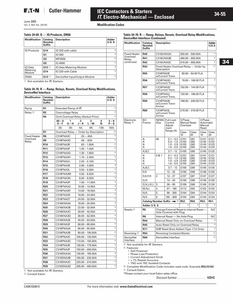
June 2005
CA08102001E For more information visit: www.EatonElectrical.com
34-55IEC Contactors & Starters
34
IT. Electro-Mechanical — EnclosedModification CodesVol. 2, Ref. No. [0319]
Table 34-69. Q — IQ Products, DN50
� Not available for IT. Starters.
Table 34-70. R — Ramp, Relays, Resets, Overload Relay Modifications, DeviceNet Interface
� Not available for IT. Starters.� Consult Eaton.
Table 34-70. R — Ramp, Relays, Resets, Overload Relay Modifications, DeviceNet Interface (Continued)
� Not available for IT. Starters.� Features:
• Self-Powered• Phase Loss Protection• Current Adjustment Knob• ± 1% Repeat Accuracy• 1NO and 1NC Isolated Contacts
� Complete Modification Code includes reset code. Example R52/G102.� Consult Eaton. *Please contact your local Eaton sales office.
Modification CatalogNumberSuffix
Description AdderU.S. $
IQ Products Q14 IQ 220 with cable *
Q1 IQ 500 *
Q3 MP3000 *
Q5 IQ 4000 *
IQ Data MeteringModule
Q12 � IQ Data Metering Module *
Q14 IQ 220 with Cable *
DN50 Q13 � DeviceNet Input/Output Module *
Modification CatalogNumberSuffix
Description AdderU.S. $
Ramp R1 Extended Ramp of IT. *
Relay � R2 Overvoltage Relay *
R4 Omit Overload Relay (Deduct Price) *
00 – 0A – F
1G – H
2J – K
3L – M
4N
5 – 9P – S
-30. -30. -54. -90. -138. -504.
R7 Overload Relay — Order by Description �
Fixed Heater Overload Relay
R8 C316FNA3C .25 – .40A *
R9 C316FNA3D .40 – .63A *
R10 C316FNA3E .63 – 1.00A *
R11 C316FNA3F 1.00 – 1.40A *
R12 C316FNA3G 1.30 – 1.80A *
R13 C316FNA3H 1.70 – 2.40A *
R14 C316FNA3J 2.20 – 3.10A *
R15 C316FNA3K 2.80 – 4.00A *
R16 C316FNA3L 3.50 – 5.00A *
R17 C316FNA3M 4.50 – 6.50A *
R18 C316FNA3N 6.00 – 8.50A *
R19 C316FNA3P 7.50 – 11.00A *
R20 C316FNA3Q 10.00 – 14.00A *
R21 C316FNA3R 13.00 – 19.00A *
R22 C316FNA3S 18.00 – 24.00A *
R23 C316FNA3T 24.00 – 32.00A *
R24 C316KNA3A 18.00 – 25.00A *
R25 C316KNA3B 22.00 – 32.00A *
R26 C316KNA3C 29.00 – 42.00A *
R27 C316KNA3D 36.00 – 52.00A *
R28 C316KNA3E 45.00 – 63.00A *
R29 C316KNA3F 60.00 – 80.00A *
R30 C316PNA3A 65.00 – 90.00A *
R31 C316PNA3B 80.00 – 100.00A *
R32 C316PNA3C 100.00 – 135.00A *
R33 C316PNA3D 110.00 – 150.00A *
R34 C316PNA3E 130.00 – 175.00A *
R35 C316PNA3F 150.00 – 200.00A *
R36 C316SNA3A 130.00 – 185.00A *
R37 C316SNA3B 165.00 – 235.00A *
R38 C316SNA3C 220.00 – 310.00A *
R39 C316SNA3D 285.00 – 400.00A *
Modification CatalogNumberSuffix
Description AdderU.S. $
Fixed Heater Overload Relay, continued
R40 C316UNA3A 355.00 – 500.00A *
R41 C316UNA3B 465.00 – 650.00A *
R42 C316UNA3C 610.00 – 850.00A *
R43 Fixed Heater Overload Relay — Order byDescription
�
R55 C316FNA3F w/Current Trans.
60.00 – 84.00 FLA *
R56 C316FNA3G w/Current Trans.
78.00 – 108.00 FLA *
R57 C316FNA3H w/Current Trans.
102.00 – 144.00 FLA *
R58 C316FNA3J w/Current Trans.
132.00 – 186.00 FLA *
R59 C316FNA3K w/Current Trans-former
168.00 – 240.00 FLA *
R60 C316FNA3L w/Current Trans-former
210.00 – 310.00 FLA *
Electronic Relay �
IEC Frame
NEMASize
Full Load Current Adjust-ment Range (A)
3-Phase Manual Reset Overload
3-Phase Automatic/Manual Reset
Class10
Class20
Class10
Class20
AAAA
00 0.1 – 0.30.3 – 1.01.0 – 2.91.6 – 5.0
G101G102G103G104
G81G82G83G84
G141G142G143G144
G121G122G123G124
A,B,C 3.7 – 12 G105 G85 G145 G125
AAAA
0 & 1 0.1 – 0.30.3 – 1.01.0 – 2.91.6 – 5.0
G101G102G103G104
G81G82G83G84
G141G142G143G144
G121G122G123G124
A,B,C 3.7 – 12 G105 G85 G145 G125
D,E 12 – 32 G106 G86 G146 G126
D,E,F,H 2 12 – 37 G107 G87 G147 G127
G,H 14 – 45 G108 G88 G148 G128
G,H,J,K,L 3 26 – 85 G109 G89 G149 G129
M,N,L 4 57 – 180 G112 G92 G152 G132
N/A 5 96 – 300 G104 G84 G144 G124
N/A 6 192 – 600 G104 G84 G144 G124
Catalog Number Suffix ➟ � R52_ R50_ R53_ R51_
Adder U.S. $ * * * *
Resets � R5 Change External Reset to Internal Reset — Hole Covered with Plug
N/C
R6 Internal Reset — No Hole Plug N/C
R44 Manual Reset Only on Overload Relay *
R45 Auto Reset Only on Overload Relay *
R71 N3R Reset Boot Added (Type 1/12 Only) *
Reversing � R54 Reversing Contactor/Starter �
DeviceNet Interface
R69 DeviceNet Interface �
Discount Symbol . . . . . . . . . . . . . . . . . . . . . . 1CD1C
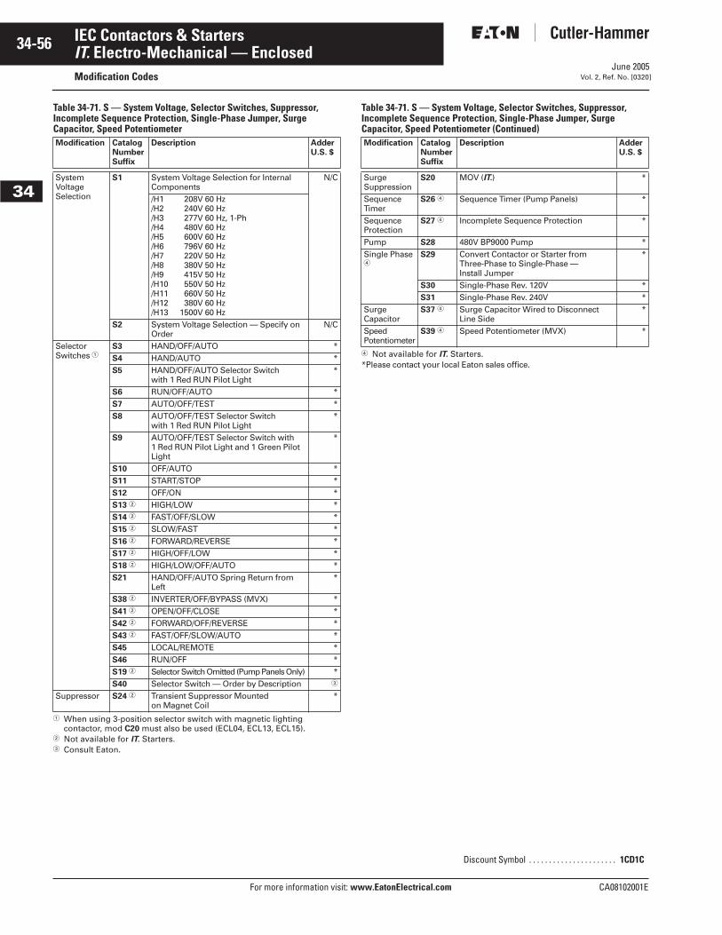
June 2005
34-56
For more information visit: www.EatonElectrical.com CA08102001E
IEC Contactors & Starters
34
IT. Electro-Mechanical — EnclosedModification Codes Vol. 2, Ref. No. [0320]
Table 34-71. S — System Voltage, Selector Switches, Suppressor, Incomplete Sequence Protection, Single-Phase Jumper, Surge Capacitor, Speed Potentiometer
� When using 3-position selector switch with magnetic lighting contactor, mod C20 must also be used (ECL04, ECL13, ECL15).
� Not available for IT. Starters.� Consult Eaton.
Table 34-71. S — System Voltage, Selector Switches, Suppressor, Incomplete Sequence Protection, Single-Phase Jumper, Surge Capacitor, Speed Potentiometer (Continued)
� Not available for IT. Starters.*Please contact your local Eaton sales office.
Modification CatalogNumberSuffix
Description AdderU.S. $
System Voltage Selection
S1 System Voltage Selection for Internal Components
N/C
/H1 208V 60 Hz/H2 240V 60 Hz/H3 277V 60 Hz, 1-Ph/H4 480V 60 Hz/H5 600V 60 Hz/H6 796V 60 Hz/H7 220V 50 Hz/H8 380V 50 Hz/H9 415V 50 Hz/H10 550V 50 Hz/H11 660V 50 Hz/H12 380V 60 Hz/H13 1500V 60 Hz
S2 System Voltage Selection — Specify on Order
N/C
Selector Switches �
S3 HAND/OFF/AUTO *S4 HAND/AUTO *S5 HAND/OFF/AUTO Selector Switch
with 1 Red RUN Pilot Light*
S6 RUN/OFF/AUTO *S7 AUTO/OFF/TEST *S8 AUTO/OFF/TEST Selector Switch
with 1 Red RUN Pilot Light*
S9 AUTO/OFF/TEST Selector Switch with 1 Red RUN Pilot Light and 1 Green Pilot Light
*
S10 OFF/AUTO *S11 START/STOP *S12 OFF/ON *S13 � HIGH/LOW *S14 � FAST/OFF/SLOW *S15 � SLOW/FAST *S16 � FORWARD/REVERSE *S17 � HIGH/OFF/LOW *S18 � HIGH/LOW/OFF/AUTO *S21 HAND/OFF/AUTO Spring Return from
Left*
S38 � INVERTER/OFF/BYPASS (MVX) *S41 � OPEN/OFF/CLOSE *S42 � FORWARD/OFF/REVERSE *S43 � FAST/OFF/SLOW/AUTO *S45 LOCAL/REMOTE *S46 RUN/OFF *S19 � Selector Switch Omitted (Pump Panels Only) *S40 Selector Switch — Order by Description �
Suppressor S24 � Transient Suppressor Mountedon Magnet Coil
*
Modification CatalogNumberSuffix
Description AdderU.S. $
SurgeSuppression
S20 MOV (IT.) *
Sequence Timer
S26 � Sequence Timer (Pump Panels) *
Sequence Protection
S27 � Incomplete Sequence Protection *
Pump S28 480V BP9000 Pump *Single Phase �
S29 Convert Contactor or Starter from Three-Phase to Single-Phase — Install Jumper
*
S30 Single-Phase Rev. 120V *S31 Single-Phase Rev. 240V *
SurgeCapacitor
S37 � Surge Capacitor Wired to Disconnect Line Side
*
Speed Potentiometer
S39 � Speed Potentiometer (MVX) *
Discount Symbol . . . . . . . . . . . . . . . . . . . . . . 1CD1C
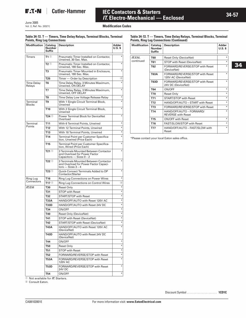
June 2005
CA08102001E For more information visit: www.EatonElectrical.com
34-57IEC Contactors & Starters
34
IT. Electro-Mechanical — EnclosedModification CodesVol. 2, Ref. No. [0321]
Table 34-72. T — Timers, Time Delay Relays, Terminal Blocks, Terminal Points, Ring Lug Connections
� Not available for IT. Starters.� Consult Eaton.
Table 34-72. T — Timers, Time Delay Relays, Terminal Blocks, Terminal Points, Ring Lug Connections (Continued)
*Please contact your local Eaton sales office.
Modification CatalogNumberSuffix
Description AdderU.S. $
Timers T1 � Pneumatic Timer Installed on Contactor, Unwired, 30 Sec. Max.
*
T2 � Pneumatic Timer Installed on Contactor, Unwired, 180 Sec. Max.
*
T3 Pneumatic Timer Mounted in Enclosure, Unwired, 180 Sec. Max.
*
T25 Timer — Order by Description �
Time DelayRelays
T6 Time Delay Relay, 3 Minutes Maximum, Unwired, ON DELAY
*
T7 Time Delay Relay, 3 Minutes Maximum, Unwired, OFF DELAY
*
T8 Time Delay Low Voltage Release Relay *
TerminalBlocks
T9 With 1 Single Circuit Terminal Block, Unwired
*
T10 With 2 Single Circuit Terminal Block, Unwired
*
T24 � Power Terminal Block for DeviceNet Overload
*
TerminalPoints
T11 With 6 Terminal Points, Unwired *
T12 With 12 Terminal Points, Unwired *
T13 With 18 Terminal Points, Unwired *
T14 Terminal Point per Customer Specifica-tion, Unwired (Price Each)
*
T15 Terminal Point per Customer Specifica-tion, Wired (Price Each)
*
T21 � 3 Terminals Mounted Between Contactor and Overload for Power Factor Capacitors — Sizes 0 – 2
*
T22 � 3 Terminals Mounted Between Contactor and Overload for Power Factor Capaci-tors — Sizes 3 – 4
*
T23 � Quick-Connect Terminals Added to DP Contactor/Starter
*
Ring LugConnectors
T16 Ring Lug Connections on Power Wires *
T17 � Ring Lug Connections on Control Wires �
IT./EM T30 Reset Only *
T31 STOP with Reset *
T32 START/STOP with Reset *
T33A HAND/OFF/AUTO with Reset 120V AC *
T33D HAND/OFF/AUTO with Reset 24V DC *
T34 ON/OFF *
T40 Reset Only (DeviceNet) *
T41 STOP with Reset (DeviceNet) *
T42 START/STOP with Reset (DeviceNet) *
T43A HAND/OFF/AUTO with Reset 120V AC (DeviceNet)
*
T43D HAND/OFF/AUTO with Reset 24V DC (DeviceNet)
*
T44 ON/OFF *
T50 Reset Only *
T51 STOP with Reset *
T52 FORWARD/REVERSE/STOP with Reset *
T53A FORWARD/REVERSE/STOP with Reset 120V AC
*
T53D FORWARD/REVERSE/STOP with Reset 24V DC
*
T54 ON/OFF *
Modification CatalogNumberSuffix
Description AdderU.S. $
IT./EM, continued
T60 Reset Only (DeviceNet) *
T61 STOP with Reset (DeviceNet) *
T62 FORWARD/REVERSE/STOP with Reset (DeviceNet)
*
T63A FORWARD/REVERSE/STOP with Reset 120V AC (DeviceNet)
*
T63D FORWARD/REVERSE/STOP with Reset 24V DC (DeviceNet)
*
T64 ON/OFF *
T70 Reset Only *
T71 START/STOP with Reset *
T72 HAND/OFF/AUTO – START with Reset *
T73 FORWARD/REVERSE/STOP with Reset *
T74 HAND/OFF/AUTO – FORWARD/REVERSE with Reset
*
T75 ON/OFF with Reset *
T76 FAST/SLOW/STOP with Reset *
T77 HAND/OFF/AUTO – FAST/SLOW with Reset
*
Discount Symbol . . . . . . . . . . . . . . . . . . . . . . 1CD1C
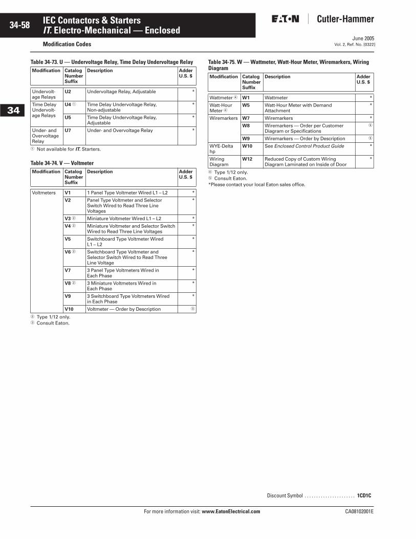
June 2005
34-58
For more information visit: www.EatonElectrical.com CA08102001E
IEC Contactors & Starters
34
IT. Electro-Mechanical — EnclosedModification Codes Vol. 2, Ref. No. [0322]
Table 34-73. U — Undervoltage Relay, Time Delay Undervoltage Relay
� Not available for IT. Starters.
Table 34-74. V — Voltmeter
� Type 1/12 only.� Consult Eaton.
Table 34-75. W — Wattmeter, Watt-Hour Meter, Wiremarkers, Wiring Diagram
� Type 1/12 only.� Consult Eaton.*Please contact your local Eaton sales office.
Modification CatalogNumberSuffix
Description AdderU.S. $
Undervolt-age Relays
U2 Undervoltage Relay, Adjustable *
Time Delay Undervolt-age Relays
U4 � Time Delay Undervoltage Relay,Non-adjustable
*
U5 Time Delay Undervoltage Relay, Adjustable
*
Under- and Overvoltage Relay
U7 Under- and Overvoltage Relay *
Modification CatalogNumberSuffix
Description AdderU.S. $
Voltmeters V1 1 Panel Type Voltmeter Wired L1 – L2 *
V2 Panel Type Voltmeter and Selector Switch Wired to Read Three Line Voltages
*
V3 � Miniature Voltmeter Wired L1 – L2 *
V4 � Miniature Voltmeter and Selector Switch Wired to Read Three Line Voltages
*
V5 Switchboard Type Voltmeter Wired L1 – L2
*
V6 � Switchboard Type Voltmeter and Selector Switch Wired to Read Three Line Voltage
*
V7 3 Panel Type Voltmeters Wired in Each Phase
*
V8 � 3 Miniature Voltmeters Wired in Each Phase
*
V9 3 Switchboard Type Voltmeters Wired in Each Phase
*
V10 Voltmeter — Order by Description �
Modification CatalogNumberSuffix
Description AdderU.S. $
Wattmeter � W1 Wattmeter *
Watt-Hour Meter �
W5 Watt-Hour Meter with Demand Attachment
*
Wiremarkers W7 Wiremarkers *
W8 Wiremarkers — Order per Customer Diagram or Specifications
�
W9 Wiremarkers — Order by Description �
WYE-Delta hp
W10 See Enclosed Control Product Guide *
Wiring Diagram
W12 Reduced Copy of Custom Wiring Diagram Laminated on Inside of Door
*
Discount Symbol . . . . . . . . . . . . . . . . . . . . . . 1CD1C
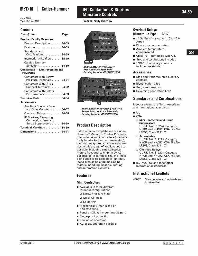
June 2005
CA08102001E For more information visit: www.EatonElectrical.com
34-59IEC Contactors & Starters
34
Miniature ControlsProduct Family OverviewVol. 2, Ref. No. [0323]
ContentsDescription Page
Product Family Overview
Product Description . . . . . . 34-59
Features . . . . . . . . . . . . . . . 34-59
Standards and Certifications . . . . . . . . . . 34-59
Instructional Leaflets . . . . . 34-59
Catalog Number Selection . . . . . . . . . . . . . 34-60
Contactors — Non-reversing andReversing
Contactors with Screw Pressure Terminals . . . . . 34-61
Contactors with Quick Connect Terminals. . . . . . 34-62
Contactors with Solder Pin Terminals . . . . . . . . . . 34-63
Technical Data . . . . . . . . . . . . . 34-64
Accessories
Auxiliary Contacts Front and Side Mounted. . . . . . 34-67
Overload Relays . . . . . . . . . 34-68
ID Markers, Reversing Connection Links and Surge Suppressors . . . . . 34-69
Terminal Markings . . . . . . . . . 34-69
Dimensions . . . . . . . . . . . . . . . 34-71
Product DescriptionEaton offers a complete line of Cutler-Hammer® Miniature Control Products that includes mini contactors (mechan-ically interlocked and non-reversing), overload relays and snap-on accesso-ries. A wide range of applications are possible, including small electrical motors fractional to 5 hp (480V AC). Because of its compact size, the line is best suited to be applied in light duty loads such as hoisting, packaging, material handling, heating, lighting and automation systems.
Features
Mini Contactors■ Available in three different
terminal configurations:❑ Screw Pressure Plate❑ Quick Connect❑ Solder Pin
■ Mechanically interlocked or non-reversing
■ Panel or DIN rail mounting (35 mm)■ Fingerproof protection■ Low noise operation■ AC or DC operation possible
Overload Relays (Bimetallic Type — C312)■ 11 Settings — to cover .10 to 12.0
Amps■ Phase loss compensated■ Ambient temperature
compensated■ Class 10 — Bimetallic type O.L.■ Stop and test buttons included■ 1NO-1NC auxiliary contacts
included as standard
Accessories■ Side and front mounted auxiliary
contacts■ Identification clips■ Surge suppressors■ Reversing connection links
Standards and CertificationsMeet or exceed the North American and International standards:
■ UL■ CSA
❑ Mini Contactors and Surge SuppressorsUL File No. E19224, Category NLDX and NLDX2; CSA File No. LR353, Class 3211-07
❑ AccessoriesUL File No. E19223, Category NKCR and NKCR2; CSA File No. LR353, Class 3211-07
❑ Overload RelaysUL File No. E19223, Category NKCR and NKCR2; CSA File No. LR353, Class 3211-03
■ IEC, VDE, CE and most other International standards
Instructional Leaflets49097 Minicontactors, Overloads and
Accessories
Mini Contactor with Screw Pressure Plate TerminalsCatalog Number CE12BNC310B
Mini Contactor Reversing Pair withScrew Pressure Plate TerminalsCatalog Number CE52CNC310H
�������
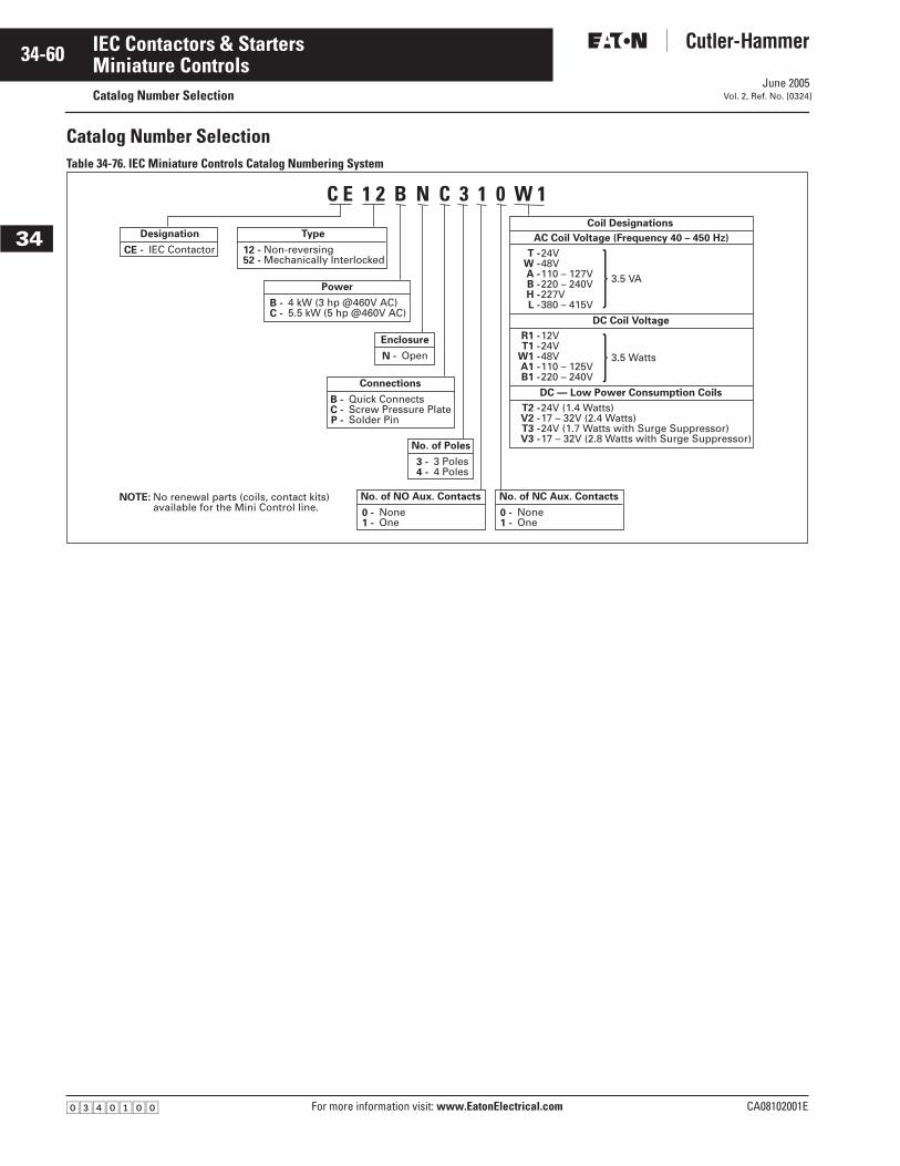
June 2005
34-60
For more information visit: www.EatonElectrical.com CA08102001E
IEC Contactors & Starters
34
Miniature ControlsCatalog Number Selection Vol. 2, Ref. No. [0324]
Catalog Number SelectionTable 34-76. IEC Miniature Controls Catalog Numbering System
Coil Designations
AC Coil Voltage (Frequency 40 – 450 Hz)
DC Coil Voltage
No. of NC Aux. Contacts
24V48V110 – 127V220 – 240V227V380 – 415V
12V24V48V110 – 125V220 – 240V
24V (1.4 Watts)17 – 32V (2.4 Watts)24V (1.7 Watts with Surge Suppressor)17 – 32V (2.8 Watts with Surge Suppressor)
3.5 VA
3.5 Watts
T -W -A -B -H -L -
R1 -T1 -
W1 -A1 -B1 -
T2 -V2 -T3 -V3 -
NoneOne
0 -1 -
DC — Low Power Consumption Coils
No. of NO Aux. Contacts
NoneOne
0 -1 -
Type
Non-reversingMechanically Interlocked
12 -52 -
Designation
IEC ContactorCE -
Connections
Quick ConnectsScrew Pressure PlateSolder Pin
B -C -P -
No. of Poles
3 Poles4 Poles
3 -4 -
Power
4 kW (3 hp @460V AC)5.5 kW (5 hp @460V AC)
B -C -
Enclosure
OpenN -
NOTE: No renewal parts (coils, contact kits) available for the Mini Control line.
C E 1 2 B N C 3 1 0 W 1
�������

June 2005
CA08102001E For more information visit: www.EatonElectrical.com
34-61IEC Contactors & Starters
34
Miniature Controls Contactors — Non-reversing and ReversingVol. 2, Ref. No. [0325]
Product SelectionNon-reversing/Reversing Contactors with Screw Pressure Terminals
Table 34-77. Non-reversing Contactor — Screw Pressure Plate Terminals
Table 34-78. Reversing Contactor — Screw Pressure Plate Terminals �
� Screw pressure plate terminal contactors are supplied standard with reversing connection links included.
Table 34-79. AC Coil Selection Table
� AC coils have an integrated protective circuit-rectifier bridge and varistor included.
Table 34-80. DC Coil Selection Table
� Auxiliary contacts can not be used with Low Power Consumption DC Coils Suffix designations: T2, V2, T3 and V3.
� For DC coils with Suffix designations T2, V2, T3 and V3, a Price Adder must be applied to the DC Coil List Price in Tables 34-77 and 34-78. See Table 34-81 below.
Table 34-81. Price Adder for Low Wattage DC Coils
Max. AC-3AmpRating(400V)
IEC 947AC-1ThermalCurrent(400V)
kW RatingAC-3400/440V
Maximum UL Horsepower No. ofPowerPoles
Aux.Contacts
CatalogNumber
Price U.S. $
1-Phase Horsepower Ratings 3-Phase Horsepower Ratings ACCoil
DCCoil110/
120V220/240V
480/600V
110/120V
200/208V
220/240V
440/480V
550/600V
999
161616
444
1/21/21/2
111
NoneNoneNone
111
111
222
333
333
334
1NO1NCNone
CE12BNC310_CE12BNC301_CE12BNC400_
75.0075.0075.00
83.0083.0083.00
121212
202020
5.55.55.5
3/43/43/4
1-1/21-1/21-1/2
222
111
222
333
555
555
334
1NO1NCNone
CE12CNC310_CE12CNC301_CE12CNC400_
97.0097.0097.00
102.00102.00102.00
Max. AC-3AmpRating(400V)
IEC 947AC-1ThermalCurrent(400V)
kW RatingAC-3400/440V
Maximum UL Horsepower No. ofPowerPoles
Aux.Contacts
CatalogNumber
Price U.S. $
1-Phase Horsepower Ratings 3-Phase Horsepower Ratings ACCoil
DCCoil110/
120V220/240V
480/600V
110/120V
200/208V
220/240V
440/480V
550/600V
99
1616
44
1/21/2
11
NoneNone
11
11
22
33
33
33
1NO1NC
CE52BNC310_CE52BNC301_
168.00168.00
184.00184.00
1212
2020
5.55.5
3/43/4
1-1/21-1/2
22
11
22
33
55
55
33
1NO1NC
CE52CNC310_CE52CNC301_
215.00215.00
224.00224.00
Screw Pressure Plate Terminals — Non-reversing Contactor
Screw Pressure Plate Terminals — Reversing Contactor
Coil Voltage Frequency40 – 450 Hz
SuffixCode �
2448
110 – 127220 – 240277380 – 415
3.5 VA3.5 VA3.5 VA3.5 VA3.5 VA3.5 VA
TWABHL
Coil Voltage SuffixCode
122448
110 – 125220 – 240
3.5 Watts3.5 Watts3.5 Watts3.5 Watts3.5 Watts
R1T1W1A1B1
DC Low Power Consumption Coils: Non-reversing Mini Contactors ��
24 (1.4 Watts)17 – 32 (2.4 Watts)24 (1.7 Watts with Surge Suppressor)17 – 32 (2.8 Watts with Surge Suppressor)
T2 �
V2 �
T3 �
V3 �
Discount Symbol . . . . . . . . . . . . . . . . . . . . . . . . . 1CD7
Devices Suffix Designations AdderU.S. $
4 kW T2 & V2T3 & V3
37.5042.50
5 kW T2 & V2T3 & V3
38.5043.50
�������
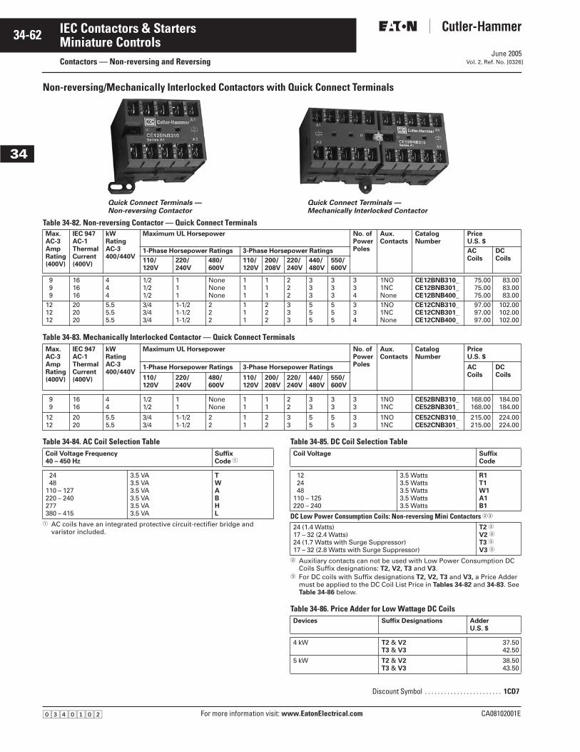
June 2005
34-62
For more information visit: www.EatonElectrical.com CA08102001E
IEC Contactors & Starters
34
Miniature ControlsContactors — Non-reversing and Reversing Vol. 2, Ref. No. [0326]
Non-reversing/Mechanically Interlocked Contactors with Quick Connect Terminals
Table 34-82. Non-reversing Contactor — Quick Connect Terminals
Table 34-83. Mechanically Interlocked Contactor — Quick Connect Terminals
Table 34-84. AC Coil Selection Table
� AC coils have an integrated protective circuit-rectifier bridge and varistor included.
Table 34-85. DC Coil Selection Table
� Auxiliary contacts can not be used with Low Power Consumption DC Coils Suffix designations: T2, V2, T3 and V3.
� For DC coils with Suffix designations T2, V2, T3 and V3, a Price Adder must be applied to the DC Coil List Price in Tables 34-82 and 34-83. See Table 34-86 below.
Table 34-86. Price Adder for Low Wattage DC Coils
Max. AC-3AmpRating(400V)
IEC 947AC-1ThermalCurrent(400V)
kW RatingAC-3400/440V
Maximum UL Horsepower No. ofPowerPoles
Aux.Contacts
CatalogNumber
PriceU.S. $
1-Phase Horsepower Ratings 3-Phase Horsepower Ratings ACCoils
DCCoils110/
120V220/240V
480/600V
110/120V
200/208V
220/240V
440/480V
550/600V
999
161616
444
1/21/21/2
111
NoneNoneNone
111
111
222
333
333
334
1NO1NCNone
CE12BNB310_CE12BNB301_CE12BNB400_
75.0075.0075.00
83.0083.0083.00
121212
202020
5.55.55.5
3/43/43/4
1-1/21-1/21-1/2
222
111
222
333
555
555
334
1NO1NCNone
CE12CNB310_CE12CNB301_CE12CNB400_
97.0097.0097.00
102.00102.00102.00
Max. AC-3AmpRating(400V)
IEC 947AC-1ThermalCurrent(400V)
kW RatingAC-3400/440V
Maximum UL Horsepower No. ofPowerPoles
Aux.Contacts
CatalogNumber
PriceU.S. $
1-Phase Horsepower Ratings 3-Phase Horsepower Ratings ACCoils
DC Coils110/
120V220/240V
480/600V
110/120V
200/208V
220/240V
440/480V
550/600V
99
1616
44
1/21/2
11
NoneNone
11
11
22
33
33
33
1NO1NC
CE52BNB310_CE52BNB301_
168.00168.00
184.00184.00
1212
2020
5.55.5
3/43/4
1-1/21-1/2
22
11
22
33
55
55
33
1NO1NC
CE52CNB310_CE52CNB301_
215.00215.00
224.00224.00
Quick Connect Terminals —Non-reversing Contactor
Quick Connect Terminals — Mechanically Interlocked Contactor
Coil Voltage Frequency40 – 450 Hz
SuffixCode �
2448
110 – 127220 – 240277380 – 415
3.5 VA3.5 VA3.5 VA3.5 VA3.5 VA3.5 VA
TWABHL
Coil Voltage SuffixCode
122448
110 – 125220 – 240
3.5 Watts3.5 Watts3.5 Watts3.5 Watts3.5 Watts
R1T1W1A1B1
DC Low Power Consumption Coils: Non-reversing Mini Contactors ��
24 (1.4 Watts)17 – 32 (2.4 Watts)24 (1.7 Watts with Surge Suppressor)17 – 32 (2.8 Watts with Surge Suppressor)
T2 �
V2 �
T3 �
V3 �
Discount Symbol . . . . . . . . . . . . . . . . . . . . . . . . 1CD7
Devices Suffix Designations AdderU.S. $
4 kW T2 & V2T3 & V3
37.5042.50
5 kW T2 & V2T3 & V3
38.5043.50
�������
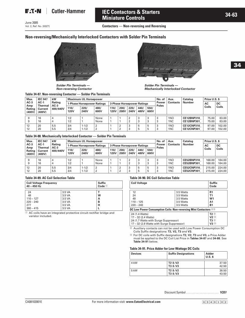
June 2005
CA08102001E For more information visit: www.EatonElectrical.com
34-63IEC Contactors & Starters
34
Miniature ControlsContactors — Non-reversing and Reversing Vol. 2, Ref. No. [0327]
Non-reversing/Mechanically Interlocked Contactors with Solder Pin Terminals
Table 34-87. Non-reversing Contactor — Solder Pin Terminals
Table 34-88. Mechanically Interlocked Contactor — Solder Pin Terminals
Table 34-89. AC Coil Selection Table
� AC coils have an integrated protective circuit-rectifier bridge and varistor included.
Table 34-90. DC Coil Selection Table
� Auxiliary contacts can not be used with Low Power Consumption DC Coils Suffix designations: T2, V2, T3 and V3.
� For DC coils with Suffix designations T2, V2, T3 and V3, a Price Adder must be applied to the DC Coil List Price in Tables 34-87 and 34-88. See Table 34-91 below.
Table 34-91. Price Adder for Low Wattage DC Coils
Max. AC-3AmpRating(400V)
IEC 947AC-1ThermalCurrent(400V)
kW RatingAC-3400/440V
Maximum UL Horsepower No. ofPowerPoles
Aux.Contacts
CatalogNumber
Price U.S. $
1-Phase Horsepower Ratings 3-Phase Horsepower Ratings ACCoils
DCCoils110/
120V220/240V
480/600V
110/120V
200/208V
220/240V
440/480V
550/600V
99
1616
44
1/21/2
11
NoneNone
11
11
22
33
33
33
1NO1NC
CE12BNP310_CE12BNP301_
75.0075.00
83.0083.00
1212
2020
5.55.5
3/43/4
1-1/21-1/2
22
11
22
33
55
55
33
1NO1NC
CE12CNP310_CE12CNP301_
97.0097.00
102.00102.00
Max. AC-3AmpRating(400V)
IEC 947AC-1ThermalCurrent(400V)
kW RatingAC-3400/440V
Maximum UL Horsepower No. ofPowerPoles
Aux.Contacts
CatalogNumber
Price U.S. $
1-Phase Horsepower Ratings 3-Phase Horsepower Ratings ACCoils
DCCoils110/
120V220/240V
480/600V
110/120V
200/208V
220/240V
440/480V
550/600V
99
1616
44
1/21/2
11
NoneNone
11
11
22
33
33
33
1NO1NC
CE52BNP310_CE52BNP301_
168.00168.00
184.00184.00
1212
2020
5.55.5
3/43/4
1-1/21-1/2
22
11
22
33
55
55
33
1NO1NC
CE52CNP310_CE52CNP301_
215.00215.00
224.00224.00
Solder Pin Terminals — Non-reversing Contactor
Solder Pin Terminals — Mechanically Interlocked Contactor
Coil Voltage Frequency40 – 450 Hz
SuffixCode �
2448
110 – 127220 – 240277380 – 415
3.5 VA3.5 VA3.5 VA3.5 VA3.5 VA3.5 VA
TWABHL
Coil Voltage SuffixCode
122448
110 – 125220 – 240
3.5 Watts3.5 Watts3.5 Watts3.5 Watts3.5 Watts
R1T1W1A1B1
DC Low Power Consumption Coils: Non-reversing Mini Contactors ��
24 (1.4 Watts)17 – 32 (2.4 Watts)24 (1.7 Watts with Surge Suppressor)17 – 32 (2.8 Watts with Surge Suppressor)
T2 �
V2 �
T3 �
V3 �
Discount Symbol . . . . . . . . . . . . . . . . . . . . . . . . 1CD7
Devices Suffix Designations AdderU.S. $
4 kW T2 & V2T3 & V3
37.5042.50
5 kW T2 & V2T3 & V3
38.5043.50
�������

June 2005
34-64
For more information visit: www.EatonElectrical.com CA08102001E
IEC Contactors & Starters
34
Miniature ControlsTechnical Data and Specifications Vol. 2, Ref. No. [0328]
Mini Contactors Technical Data
Conformity to Standards■ IEC 947-4-1, 947-5-1, CE■ UL 508, CSA, 22.2
Specifications■ Insulation Voltage VI: 690V■ Ambient Temperature:
❑ Contactor: -13° to 131°F (-25° to +55°C)❑ Contactor and Overload Relay: -13° to 122°F
(-25° to +50°C)❑ Storage: -40° to 176°F (-40° to +80°C)
■ Finger Protection: IP20■ Impulse Withstand Voltage (Uimp): 6 kV■ Climatic Resistance:
❑ Acc. to DIN 50 017❑ Acc. to UTE C 63 – 100: Alternating climate proof
30 cycles, version I■ Mounting Position: Vertical/horizontal (any position)■ Max. Switching Frequency:
❑ AC-1 cyc./h: 300❑ DC-1, DC-3, DC-5, AC-2, AC-3 cyc./h: 600
Table 34-92. Switching Times
Table 34-93. Current Ratings (I) IEC 947-4-1
■ Electrical Life — Details: See endurance curves on Page 34-65
■ Mechanical Life: 10,000,000 operations■ Power Loss per Pole: 2W at 20A■ Backup Fuse, Type gG, Type 1: 20A (CE12B); 25A (CE12C)■ Backup Fuse, Type gG, Type 2: 20A■ Terminal Capacity — Stranded Copper 167°F (75°C) or Equiv-
alent, Single Wire: 12 – 22 AWG; Two Wires: 12 – 18 AWG■ Terminal Capacity for Reversible Pair — Stranded Copper
167°F (75°C) or Equivalent: 12 – 16 AWG
Table 34-94. Shock Resistance CE12 (B or C)
� 1/2 Sinusoidal Shock, 10 ms: No Change in Contact Position
Table 34-95. Utilization Categories, DC Loadings for Both CE12 (B or C)
Coil Technical DataTable 34-96. Coil for AC and DC Operations
� AC coils have an integrated protective circuit-rectifier bridge and varistor included.
� Low Power Consumption DC Coils can not be used with Reversing Mini Contactors.
Table 34-97. Mini Contactors to Connect to PLCs
� Low Power Consumption DC Coils can not be used with Reversing Mini Contactors.
� Us = coil voltage rating.
CE12B (4 kW) CE12C (5.5 kW)
AC Contactor
DC Contactor
ACContractor
DC Contactor
Closing Delay — NO ms 14 to 26 14 to 26
Opening Delay — NO ms 16 to 40 4 to 10 16 to 40 4 to 10
Closing Delay — NC ms 16 to 40 4 to 10 16 to 40 4 to 10
Opening Delay — NC ms 14 to 26 14 to 26
AC-1 Thermal Current Ith CE12B (4 kW) CE12C (5.5 kW)
Ie Ie
131°F (55°C)
104°F (40°C)
131°F(55°C)
104°F(40°C)
220/240V 16A 20A 16A 20A
380/440V 16A 20A 16A 20A
500V 12A 12A 12A 12A
AC-2, AC-3 (Ie) kW Ie kW Ie
220/240V 2.2 9A 3 12/11A
380/440V 4.0 9/8A 5.5 12/11A
500V 3.0 5.5A 4.0 7.0A
AC-4 Refer to Specific Load Life Curves
ShockDirections
A � B1 � B2 � C1 � C2 � Standard Mounting Position
Contactor ON 20g 20g 20g 20g 20g
Contactor OFF 10g 20g 20g 20g 20g
Utilization Category DC-1L/R ≤ 1 ms
DC-3L/R ≤ 2 ms
DC-5L/R ≤ 7.5 ms
Ie Amps
24V48V60V
110V220V
16.016.016.07.0.8
16.08.04.01.5.25
16.02.01.25.40.20
24V48V60V
110V220V
16.016.016.016.05.0
16.016.015.07.01.5
16.016.012.02.0.5
24V48V60V
110V220V
16.016.016.016.014.0
16.016.016.015.04.0
16.016.016.08.02.0
Rated Power Inrush Seal
Contactors: CE12, CE52 (4 and 5.5 kW) for AC Operation �
3.5 VA 3.5 VA
Contactors: CE12B, CE52 (4 and 5.5 kW) for DC Operation
3.5W 3.5W
Contactors with Low Power Consumption Power Coils: �
CE12B (1.4W, 24V DC — Coil Suffix T2)CE12B (2.4W, 17 – 32V DC — Coil Suffix V2)
1.4W2.4W
1.4W2.4W
Cold Hot
I mA P W I mA P W
CE12B (1.7W, 24V DC — Coil Suffix T3) �
77 1.75 60 1.35
CE12B (2.8W, 17 – 32V DC — Coil Suffix V3) �
125 2.8 94 2.10
Coil Voltage Range .85 – 1.1 x Us �
A
B2
B1
C2
C1
A
+ -
+ -+
++ -
�������
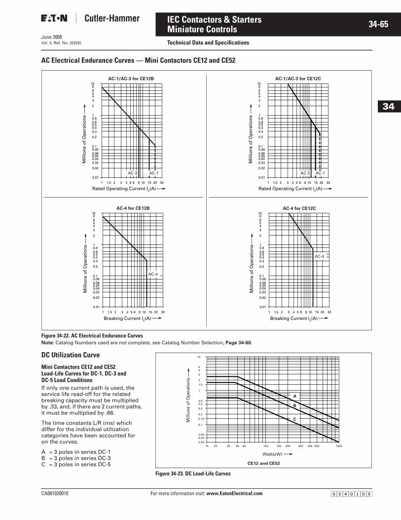
June 2005
CA08102001E For more information visit: www.EatonElectrical.com
34-65IEC Contactors & Starters
34
Miniature ControlsTechnical Data and SpecificationsVol. 2, Ref. No. [0329]
AC Electrical Endurance Curves — Mini Contactors CE12 and CE52
Figure 34-22. AC Electrical Endurance CurvesNote: Catalog Numbers used are not complete, see Catalog Number Selection, Page 34-60.
DC Utilization Curve
Mini Contactors CE12 and CE52 Load-Life Curves for DC-1, DC-3 and DC-5 Load ConditionsIf only one current path is used, the service life read-off for the related breaking capacity must be multiplied by .33, and, if there are 2 current paths, it must be multiplied by .66.
The time constants L/R (ms) which differ for the individual utilization categories have been accounted for on the curves.
A = 3 poles in series DC-1B = 3 poles in series DC-3C = 3 poles in series DC-5
Figure 34-23. DC Load-Life Curves
10 30201.51 2 3 4 5 6 8
Rated Operating Current Ic(A)15
Mill
ion
s o
f O
per
atio
ns
0.01
0.1
1
2
0.02
0.030.040.050.060.08
0.2
0.30.40.50.60.8
3
AC-3 AC-1
4568
10AC-1/AC-3 for CE12B
10 30201.51 2 3 4 5 6 8
Breaking Current Ic(A)15
Mill
ion
s o
f O
per
atio
ns
0.01
0.1
1
2
0.02
0.030.040.050.060.08
0.2
0.30.40.50.60.8
3
AC-4
4568
10AC-4 for CE12B
10 30201.51 2 3 4 5 6 8
Rated Operating Current Ic(A)15
Mill
ion
s o
f O
per
atio
ns
0.01
0.1
1
2
0.02
0.030.040.050.060.08
0.2
0.30.40.50.60.8
34568
10AC-1/AC-3 for CE12C
AC-3 AC-1
10 30201.51 2 3 4 5 6 8
Breaking Current Ic(A)15
Mill
ion
s o
f O
per
atio
ns
0.01
0.1
1
2
0.02
0.030.040.050.060.08
0.2
0.30.40.50.60.8
34
AC-4
568
10AC-4 for CE12C
150.03
0.040.05
0.1
0.15
0.2
0.3
0.40.5
1
1.5
2
3
45
10
20 30 40 50 100 150 200 300 400 500 1000
Watts(W)
Mill
ions
of O
pera
tions
CE12 and CE52
A
B
C
�������
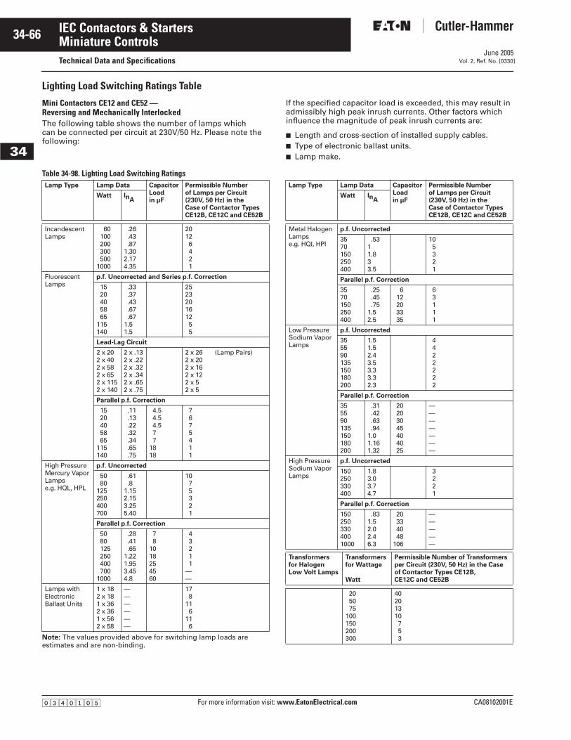
June 2005
34-66
For more information visit: www.EatonElectrical.com CA08102001E
IEC Contactors & Starters
34
Miniature ControlsTechnical Data and Specifications Vol. 2, Ref. No. [0330]
Lighting Load Switching Ratings Table
Mini Contactors CE12 and CE52 — Reversing and Mechanically InterlockedThe following table shows the number of lamps which can be connected per circuit at 230V/50 Hz. Please note the following:
If the specified capacitor load is exceeded, this may result in admissibly high peak inrush currents. Other factors which influence the magnitude of peak inrush currents are:
■ Length and cross-section of installed supply cables.■ Type of electronic ballast units.■ Lamp make.
Table 34-98. Lighting Load Switching Ratings
Note: The values provided above for switching lamp loads are estimates and are non-binding.
Lamp Type Lamp Data Capacitor
Loadin µF
Permissible Numberof Lamps per Circuit(230V, 50 Hz) in theCase of Contactor TypesCE12B, CE12C and CE52B
Watt InA
IncandescentLamps
60100200300500
1000
.26
.43
.871.302.174.35
20126421
FluorescentLamps
p.f. Uncorrected and Series p.f. Correction
1520405865
115140
.33
.37
.43
.67
.671.51.5
252320161255
Lead-Lag Circuit
2 x 202 x 402 x 582 x 652 x 1152 x 140
2 x .132 x .222 x .322 x .342 x .652 x .75
2 x 262 x 202 x 162 x 122 x 52 x 5
(Lamp Pairs)
Parallel p.f. Correction
1520405865
115140
.11
.13
.22
.32
.34
.65
.75
4.54.54.577
1818
7675411
High PressureMercury VaporLampse.g. HQL, HPL
p.f. Uncorrected
5080
125250400700
.61
.81.152.153.255.40
1075321
Parallel p.f. Correction
5080125250400700
1000
.28
.41
.651.221.953.454.8
78
1018254560
43211
——
Lamps withElectronicBallast Units
1 x 182 x 181 x 362 x 361 x 562 x 58
——————
178
116
116
Lamp Type Lamp Data CapacitorLoadin µF
Permissible Numberof Lamps per Circuit(230V, 50 Hz) in theCase of Contactor TypesCE12B, CE12C and CE52B
Watt InA
Metal HalogenLampse.g. HQI, HPI
p.f. Uncorrected
3570150250400
.5311.833.5
105321
Parallel p.f. Correction
3570150250400
.25
.45
.751.52.5
612203335
63111
Low PressureSodium VaporLamps
p.f. Uncorrected
355590135150180200
1.51.52.43.53.33.32.3
4422222
Parallel p.f. Correction
355590135150180200
.31
.42
.63
.941.01.161.32
20203045404025
———————
High PressureSodium VaporLamps
p.f. Uncorrected
150250330400
1.83.03.74.7
3221
Parallel p.f. Correction
1502503304001000
.831.52.02.46.3
20334048
106
—————
Transformersfor HalogenLow Volt Lamps
Transformers for Wattage
Watt
Permissible Number of Transformersper Circuit (230V, 50 Hz) in the Caseof Contactor Types CE12B,CE12C and CE52B
205075
100150200300
40201310753
�������
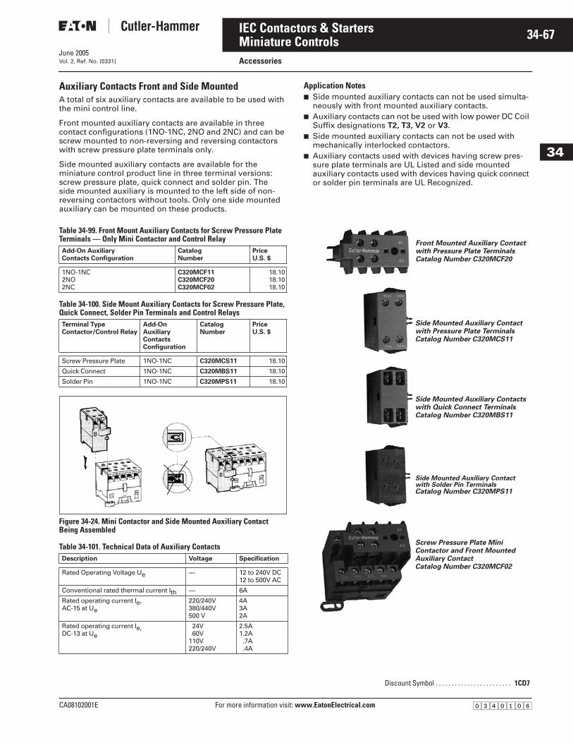
June 2005
CA08102001E For more information visit: www.EatonElectrical.com
34-67IEC Contactors & Starters
34
Miniature ControlsAccessoriesVol. 2, Ref. No. [0331]
Auxiliary Contacts Front and Side MountedA total of six auxiliary contacts are available to be used with the mini control line.
Front mounted auxiliary contacts are available in three contact configurations (1NO-1NC, 2NO and 2NC) and can be screw mounted to non-reversing and reversing contactors with screw pressure plate terminals only.
Side mounted auxiliary contacts are available for the miniature control product line in three terminal versions: screw pressure plate, quick connect and solder pin. The side mounted auxiliary is mounted to the left side of non-reversing contactors without tools. Only one side mounted auxiliary can be mounted on these products.
Application Notes■ Side mounted auxiliary contacts can not be used simulta-
neously with front mounted auxiliary contacts.■ Auxiliary contacts can not be used with low power DC Coil
Suffix designations T2, T3, V2 or V3.
■ Side mounted auxiliary contacts can not be used with mechanically interlocked contactors.
■ Auxiliary contacts used with devices having screw pres-sure plate terminals are UL Listed and side mounted auxiliary contacts used with devices having quick connect or solder pin terminals are UL Recognized.
Table 34-99. Front Mount Auxiliary Contacts for Screw Pressure Plate Terminals — Only Mini Contactor and Control Relay
Table 34-100. Side Mount Auxiliary Contacts for Screw Pressure Plate, Quick Connect, Solder Pin Terminals and Control Relays
Figure 34-24. Mini Contactor and Side Mounted Auxiliary Contact Being Assembled
Table 34-101. Technical Data of Auxiliary Contacts
Add-On AuxiliaryContacts Configuration
CatalogNumber
PriceU.S. $
1NO-1NC2NO2NC
C320MCF11C320MCF20C320MCF02
18.1018.1018.10
Terminal Type Contactor/Control Relay
Add-On Auxiliary Contacts Configuration
CatalogNumber
PriceU.S. $
Screw Pressure Plate 1NO-1NC C320MCS11 18.10
Quick Connect 1NO-1NC C320MBS11 18.10
Solder Pin 1NO-1NC C320MPS11 18.10
Description Voltage Specification
Rated Operating Voltage Ue — 12 to 240V DC12 to 500V AC
Conventional rated thermal current Ith — 6A
Rated operating current Ie, AC-15 at Ue
220/240V380/440V500 V
4A3A2A
Rated operating current Ie,DC-13 at Ue
24V60V
110V220/240V
2.5A1.2A.7A.4A
Discount Symbol . . . . . . . . . . . . . . . . . . . . . . . . 1CD7
Front Mounted Auxiliary Contact with Pressure Plate TerminalsCatalog Number C320MCF20
Side Mounted Auxiliary Contactwith Pressure Plate TerminalsCatalog Number C320MCS11
Side Mounted Auxiliary Contactswith Quick Connect TerminalsCatalog Number C320MBS11
Side Mounted Auxiliary Contactwith Solder Pin TerminalsCatalog Number C320MPS11
Screw Pressure Plate Mini Contactor and Front Mounted Auxiliary Contact Catalog Number C320MCF02
�������
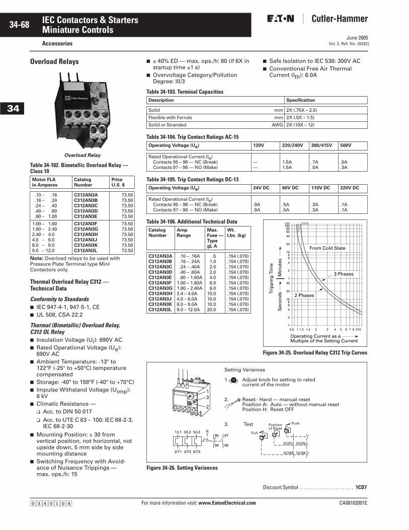
June 2005
34-68
For more information visit: www.EatonElectrical.com CA08102001E
IEC Contactors & Starters
34
Miniature ControlsAccessories Vol. 2, Ref. No. [0332]
Overload Relays
Overload Relay
Table 34-102. Bimetallic Overload Relay — Class 10
Note: Overload relays to be used with Pressure Plate Terminal type Mini Contactors only.
Thermal Overload Relay C312 — Technical Data
Conformity to Standards■ IEC 947-4-1, 947-5-1, CE■ UL 508, CSA 22.2
Thermal (Bimetallic) Overload Relay,C312 OL Relay■ Insulation Voltage (Ui): 690V AC■ Rated Operational Voltage (Ue):
690V AC■ Ambient Temperature: -13° to
122°F (-25° to +50°C) temperature compensated
■ Storage: -40° to 158°F (-40° to +70°C)■ Impulse Withstand Voltage (Uimp):
6 kV■ Climatic Resistance —
❑ Acc. to DIN 50 017❑ Acc. to UTE C 63 – 100: IEC 68-2-3,
IEC 68-2-30■ Mounting Position: ± 30 from
vertical position, not horizontal, not upside down, 5 mm side by side mounting distance
■ Switching Frequency with Avoid-ance of Nuisance Trippings — max. ops./h: 15
Motor FLAin Amperes
CatalogNumber
PriceU.S. $
.10 – .16
.16 – .24
.24 – .40
.40 – .60
.60 – 1.00
C312AN3AC312AN3BC312AN3CC312AN3DC312AN3E
73.5073.5073.5073.5073.50
1.00 – 1.601.60 – 2.402.40 – 4.04.0 – 6.06.0 – 9.09.0 – 12.0
C312AN3FC312AN3GC312AN3HC312AN3JC312AN3KC312AN3L
73.5073.5073.5073.5073.5073.50
■ ≤ 40% ED — max. ops./h: 60 (if 6X in startup time ≤1 s)
■ Overvoltage Category/Pollution Degree: III/3
■ Safe Isolation to IEC 536: 300V AC■ Conventional Free Air Thermal
Current (Ith): 6.0A
Table 34-103. Terminal Capacities
Table 34-104. Trip Contact Ratings AC-15
Table 34-105. Trip Contact Ratings DC-13
Table 34-106. Additional Technical Data
Figure 34-25. Overload Relay C312 Trip Curves
Figure 34-26. Setting Variances
Description Specification
Solid mm 2X (.75X – 2.5)
Flexible with Ferrule mm 2X (.5X – 1.5)
Solid or Stranded AWG 2X (18X – 12)
Operating Voltage (Ue) 120V 220/240V 380/415V 500V
Rated Operational Current (Ie)Contacts 95 – 96 — NC (Break)Contacts 97 – 98 — NO (Make)
——
1.5A1.5A
.7A
.5A.5A.3A
Operating Voltage (Ue) 24V DC 60V DC 110V DC 220V DC
Rated Operational Current (Ie)Contacts 95 – 96 — NC (Break)Contacts 97 – 98 — NO (Make)
.9A
.9A.5A.5A
.3A
.3A.1A.1A
CatalogNumber
AmpRange
Max. Fuse —Type gL A
Wt.Lbs. (kg)
C312AN3AC312AN3BC312AN3CC312AN3DC312AN3EC312AN3FC312AN3GC312AN3HC312AN3JC312AN3KC312AN3L
.10 – .16A
.16 – .24A
.24 – .40A
.40 – .60A
.60 – 1.00A1.00 – 1.60A1.60 – 2.40A2.4 – 4.0A4.0 – 6.0A6.0 – 9.0A9.0 – 12.0A
.51.02.02.04.06.06.0
10.010.010.020.0
.154 (.070)
.154 (.070)
.154 (.070)
.154 (.070)
.154 (.070)
.154 (.070)
.154 (.070)
.154 (.070)
.154 (.070)
.154 (.070)
.154 (.070)
0.8 11
2
4
68
10
20
40
1
2
4
68
10
20
406080
100120
1.2 1.5 2 3 4 5 6 7 8 910
Trip
pin
g T
ime
Sec
on
ds
Min
ute
s
Operating Current as aMultiple of the Setting Current
2 Phases
3 Phases
From Cold State
Setting Variances
1. Adjust knob for setting to rated current of the motor
2. Reset: Hand — manual reset Position A: Auto — without manual reset Position H: Reset OFF
3. Test
Pull
NO97 NO95
NO98 NO96
Position of Reset
Push
RT 95 97
96 98
5/L33/L21/L1
6/T34/T22/T1
13
2
Discount Symbol . . . . . . . . . . . . . . . . . . . . . . . . 1CD7
�������
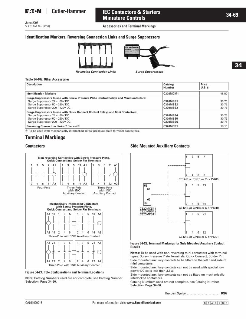
June 2005
CA08102001E For more information visit: www.EatonElectrical.com
34-69IEC Contactors & Starters
34
Miniature ControlsAccessories and Terminal MarkingsVol. 2, Ref. No. [0333]
Identification Markers, Reversing Connection Links and Surge Suppressors
Table 34-107. Other Accessories
� To be used with mechanically interlocked screw pressure plate terminal contactors.
Terminal Markings
Contactors
Figure 34-27. Pole Configurations and Terminal Locations
Note: Catalog Numbers used are not complete, see Catalog Number Selection, Page 34-60.
Side Mounted Auxiliary Contacts
Figure 34-28. Terminal Markings for Side Mounted Auxiliary Contact Blocks
Notes: To be used with non-reversing mini contactors with terminal types: Screw Pressure Plate Terminals, Quick Connect, Solder Pin.Side mounted auxiliary contacts to be fitted on the left hand side of mini contactors.Side mounted auxiliary contacts can not be used with special low power DC coils less than 3.5W.Side mounted auxiliary contacts can not be fitted on mechanically interlocked contactors.Catalog Numbers used are not complete, see Catalog Number Selection, Page 34-60.
Description CatalogNumber
PriceU.S. $
Identification Markers C320MCM1 48.50
Surge Suppressors to use with Screw Pressure Plate Control Relays and Mini Contactors:Surge Suppressor 24 – 60V DCSurge Suppressor 50 – 250V DCSurge Suppressor 200 – 420V DC
C320MSS1C320MSS2C320MSS3
30.7530.7530.75
Surge Suppressors to use with Quick Connect Control Relays and Mini Contactors:Surge Suppressor 24 – 60V DCSurge Suppressor 50 – 250V DCSurge Suppressor 200 – 420V DC
C320MSS4C320MSS5C320MSS6
30.7530.7530.75
Reversing Connection Links (2 Pieces) � C320MCR1 18.10
Surge SuppressorsReversing Connection Links
Non-reversing Contactors with Screw Pressure Plate,Quick Connect and Solder Pin Terminals
2 4 6 8 A2
1 3 5 7 A1
Four-Pole2 4 6 14 A2
1 3 5 13 A1
Three-Polewith 1NO
Auxiliary Contact
2 4 6 22 A2
1 3 5 21 A1
Three-Polewith 1NC
Auxiliary Contact
Mechanically Interlocked Contactorswith Screw Pressure Plate,
Quick Connect and Solder Pin Terminals
A2 14 2 4 6
A1 13 1 3 5
2 4 6 14 A2
1 3 5 13 A1
A2 22 2 4 6
A1 21 1 3 5
2 4 6 22 A2
1 3 5 21 A1
Three-Pole with 1NC Auxiliary Contact
Three-Pole with 1NO Auxiliary Contact
Discount Symbol . . . . . . . . . . . . . . . . . . . . . . . . 1CD7
54
5361
62
2 4 6 14
1 3 5 13
C320MCS11C320MBS11C320MPS11
CE12(B or C)N(B or C or P)400
CE12(B or C)N(B or C or P)310
CE12(B or C)N(B or C or P)301
2 4 6 22
1 3 5 21
2 4 6 8
1 3 5 7
�������
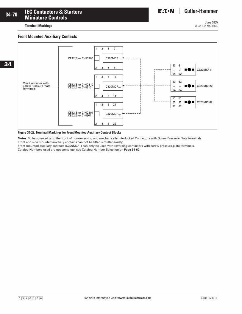
June 2005
34-70
For more information visit: www.EatonElectrical.com CA08102001E
IEC Contactors & Starters
34
Miniature ControlsTerminal Markings Vol. 2, Ref. No. [0334]
Front Mounted Auxiliary Contacts
Figure 34-29. Terminal Markings for Front Mounted Auxiliary Contact Blocks
Notes: To be screwed onto the front of non-reversing and mechanically interlocked Contactors with Screw Pressure Plate terminals.Front and side mounted auxiliary contacts can not be fitted simultaneously.Front mounted auxiliary contacts (C320MCF_) can only be used with reversing contactors with screw pressure plate terminals.Catalog Numbers used are not complete, see Catalog Number Selection on Page 34-60.
C320MCF20
C320MCF02
2
1
4
3
6
5
14
13
2
1
4
3
6
5
22
21
CE12(B or C)NC400 C320MCF…
CE12(B or C)NC310CE52(B or C)N310 C320MCF…
CE12(B or C)NC301CE52(B or C)N301 C320MCF…
Mini Contactor withScrew Pressure PlateTerminals
2
1
4
3
54
53
64
63
6
5
8
7
52
51
62
61
C320MCF1154
53
62
61
�������
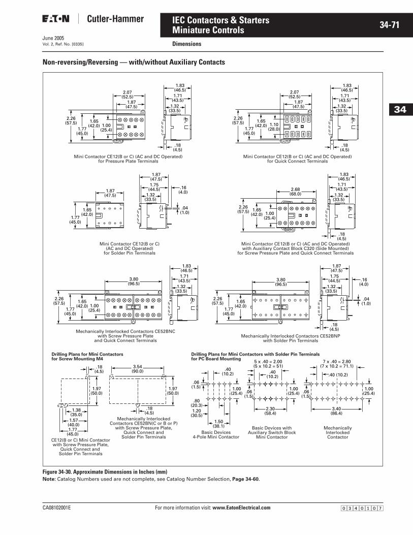
June 2005
CA08102001E For more information visit: www.EatonElectrical.com
34-71IEC Contactors & Starters
34
Miniature ControlsDimensionsVol. 2, Ref. No. [0335]
Non-reversing/Reversing — with/without Auxiliary Contacts
Figure 34-30. Approximate Dimensions in Inches (mm)Note: Catalog Numbers used are not complete, see Catalog Number Selection, Page 34-60.
1.87(47.5)
1.83(46.5)1.71
(43.5)1.32
(33.5)
.18(4.5)
2.07(52.5)
2.26(57.5)
1.77(45.0)
1.65(42.0) 1.00
(25.4)
Mini Contactor CE12(B or C) (AC and DC Operated)for Pressure Plate Terminals
1.87(47.5)
1.83(46.5)1.71
(43.5)1.32
(33.5)
.18(4.5)
2.07(52.5)
2.26(57.5)
1.77(45.0)
1.65(42.0) 1.10
(28.0)
Mini Contactor CE12(B or C) (AC and DC Operated)for Quick Connect Terminals
1.83(46.5)1.71
(43.5)1.32
(33.5)
2.26(57.5)
1.77(45.0)
1.65(42.0) 1.00
(25.4)
3.80(96.5)
Mechanically Interlocked Contactors CE52BNCwith Screw Pressure Plate
and Quick Connect Terminals
2.26(57.5)
1.77(45.0)
1.65(42.0)
3.80(96.5)
1.87(47.5)
.16(4.0)
1.75(44.5)
1.32(33.5)
.18(4.5)
.04(1.0)
Mechanically Interlocked Contactors CE52BNPwith Solder Pin Terminals
1.87(47.5)
1.87(47.5)
.16(4.0)
1.75(44.5)
1.32(33.5)
.04(1.0)
1.77(45.0)
1.65(42.0)
Mini Contactor CE12(B or C)(AC and DC Operated)
for Solder Pin Terminals
1.83(46.5)1.71
(43.5)1.32
(33.5)
.18(4.5)
2.68(68.0)
2.26(57.5) 1.65
(42.0) 1.00(25.4)
Mini Contactor CE12(B or C) (AC and DC Operated)with Auxiliary Contact Block C320 (Side Mounted)
for Screw Pressure Plate and Quick Connect Terminals
1.97(50.0)
1.38(35.0)
1.57(40.0)1.77
(45.0)
.18(4.5)
.18(4.5)
1.97(50.0)
3.54(90.0)
CE12(B or C) Mini Contactorwith Screw Pressure Plate,
Quick Connect and Solder Pin Terminals
Mechanically InterlockedContactors CE52BN(C or B or P)
with Screw Pressure Plate,Quick Connect and
Solder Pin Terminals
5 x .40 = 2.00(5 x 10.2 = 51)
.06(1.5)
2.30(58.4)
1.00(25.4)
.40(10.2)
.06(1.5)
.80(20.3)1.20
(30.5)1.50
(38.1)
1.00(25.4)
.40(10.2)
7 x .40 = 2.80(7 x 10.2 = 71.1)
.40 (10.2)
.06(1.5)
3.40(86.4)
1.00(25.4)
Basic Devices4-Pole Mini Contactor
Basic Devices withAuxiliary Switch Block
Mini Contactor
MechanicallyInterlockedContactor
Drilling Plans for Mini Contactors for Screw Mounting M4
Drilling Plans for Mini Contactors with Solder Pin Terminals for PC Board Mounting
�������

June 2005
34-72
For more information visit: www.EatonElectrical.com CA08102001E
IEC Contactors & Starters
34
Miniature ControlsDimensions Vol. 2, Ref. No. [0336]
Mini Contactor with Overload Relay
Figure 34-31. Approximate Dimensions in Inches (mm)
Auxiliary Contacts
Figure 34-32. Approximate Dimensions in Inches (mm)Note: Catalog Numbers used are not complete, see Catalog Number Selection, Page 34-60.
ø.18 (4.5) .18
(4.5)
.16 (4.0)
1.26 (32.0)
1.77 (45.0)
1.83 (46.5)
2.2 (56.0)
.26 (6.5)
1.00(25.4)
.36(9.1)
1.87(47.5)
1.38…1.77 (35…45)
1.65(42.0)
1.97(50.0)
1.85 (47.0)
4.13 (105.0)
Mini Contactor with Screw Pressure Plate Terminals and Overload Relay
CE12(B or C)NC + C312AN3
Mini Contactor with Screw Pressure Plate Terminals CE12(B or C)NCwith Screwed-On Auxiliary Contact C320MCF (Front Mounted Auxiliary Contact)
1.38 (35.0)
.39 (10.0)
1.57 (40.0)
1.77 (45.0)
.36 (9.1)
.18 (4.5)
2.32(59.0)1.71
(43.5)1.32
(33.5)
.18(4.5)
2.26(57.5)
1.77(45.0)
2.87 (73.0)
1.65(42.0) 1.97
(50.0).39
(10.1)1.14
(29.0).38
(9.6)
.22(5.5) .36
(9.1)
1.87 (47.5)
1.73 (44.0)
1.43 (36.4)
.39 (10.0)
.61 (15.5)
1.04 (26.5)
.39 (10.1)
1.14 (29.0)
C320MCF Front Mounted Auxiliary Contact to Be Used withContactor or Control Relay with Pressure Plate Terminals
.80(20.3)
1.65(42.0)
1.91 (48.5)
1.32(33.5)
1.71(43.5)
1.83 (46.5)
1.00 (25.4)
.80(20.3)
1.65(42.0)
1.91 (48.5)
1.32(33.5)
1.75(44.5)
1.87 (47.5)
.04 (1.0)
.16 (4.0) Min. .80
(20.3)
1.65(42.0)
1.91 (48.5)
1.32(33.5)
1.71(43.5)
1.83 (46.5)
1.10 (28.0)
Side Mounted to Use with Screw Pressure Plate Terminal Contactor
C320MCS11
Side Mounted to Use with Solder Pin Contactor
C320MPS11
Side Mounted to Use with Quick Connect Contactor
C320MBS11
�������
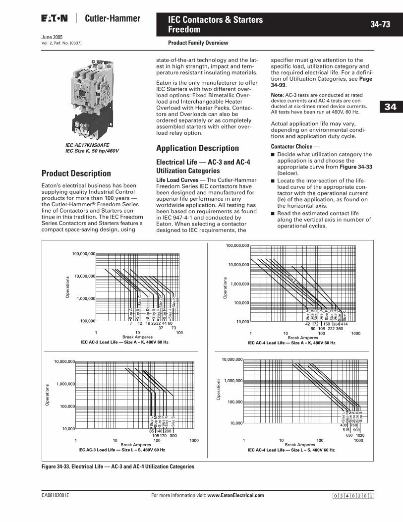
June 2005
CA08102001E For more information visit: www.EatonElectrical.com
34-73IEC Contactors & Starters
34
FreedomProduct Family OverviewVol. 2, Ref. No. [0337]
Product DescriptionEaton’s electrical business has been supplying quality Industrial Control products for more than 100 years — the Cutler-Hammer® Freedom Series line of Contactors and Starters con-tinue in this tradition. The IEC Freedom Series Contactors and Starters feature a compact space-saving design, using
state-of-the-art technology and the lat-est in high strength, impact and tem-perature resistant insulating materials.
Eaton is the only manufacturer to offer IEC Starters with two different over-load options: Fixed Bimetallic Over-load and Interchangeable Heater Overload with Heater Packs. Contac-tors and Overloads can also be ordered separately or as completely assembled starters with either over-load relay option.
Application Description
Electrical Life — AC-3 and AC-4 Utilization CategoriesLife Load Curves — The Cutler-Hammer Freedom Series IEC contactors have been designed and manufactured for superior life performance in any worldwide application. All testing has been based on requirements as found in IEC 947-4-1 and conducted by Eaton. When selecting a contactor designed to IEC requirements, the
specifier must give attention to the specific load, utilization category and the required electrical life. For a defini-tion of Utilization Categories, see Page 34-99.
Note: AC-3 tests are conducted at rated device currents and AC-4 tests are con-ducted at six-times rated device currents. All tests have been run at 460V, 60 Hz.
Actual application life may vary, depending on environmental condi-tions and application duty cycle.
Contactor Choice —■ Decide what utilization category the
application is and choose the appropriate curve from Figure 34-33 (below).
■ Locate the intersection of the life-load curve of the appropriate con-tactor with the operational current (le) of the application, as found on the horizontal axis.
■ Read the estimated contact life along the vertical axis in number of operational cycles.
Figure 34-33. Electrical Life — AC-3 and AC-4 Utilization Categories
IEC AE17KNS0AFEIEC Size K, 50 hp/460V
1
Op
erat
ion
s
100,000
1,000,000
10,000,000
100,000,000
7 12
IEC AC-3 Load Life — Size A – K, 480V 60 Hz
1837
10073
4432 6025
10Break Amperes
Siz
e A
Siz
e B
Siz
e D
Siz
e E
Siz
e F
Siz
e H
Siz
e J
Siz
e C
Siz
e G
Siz
e K
Op
erat
ion
s
10,000
100,000
1,000,000
10,000,000
IEC AC-3 Load Life — Size L – S, 480V 60 Hz
85300
200170105
140
10010 10001Break Amperes
Siz
e L
Siz
e M
Siz
e N
Siz
e P
Siz
e R
Siz
e S
Op
erat
ion
s
10,000
100,000
1,000,000
10,000,000
100,000,000
1 1000
4236010860 222
IEC AC-4 Load Life — Size A – K, 480V 60 Hz
100
26415072 414
10Break Amperes
Siz
e A
Siz
e B
Siz
e C
Siz
e D
Siz
e F
Size E
Siz
e H
Siz
e J
Siz
e K
Siz
e G
Op
erat
ion
s
10,000
100,000
1,000,000
10,000,000
IEC AC-4 Load Life — Size L – S, 480V 60 Hz
515630
900438 768
1 10001020
10010Break Amperes
Siz
e L
Siz
e M
Siz
e N
Siz
e P
Siz
e R
Siz
e S
�������
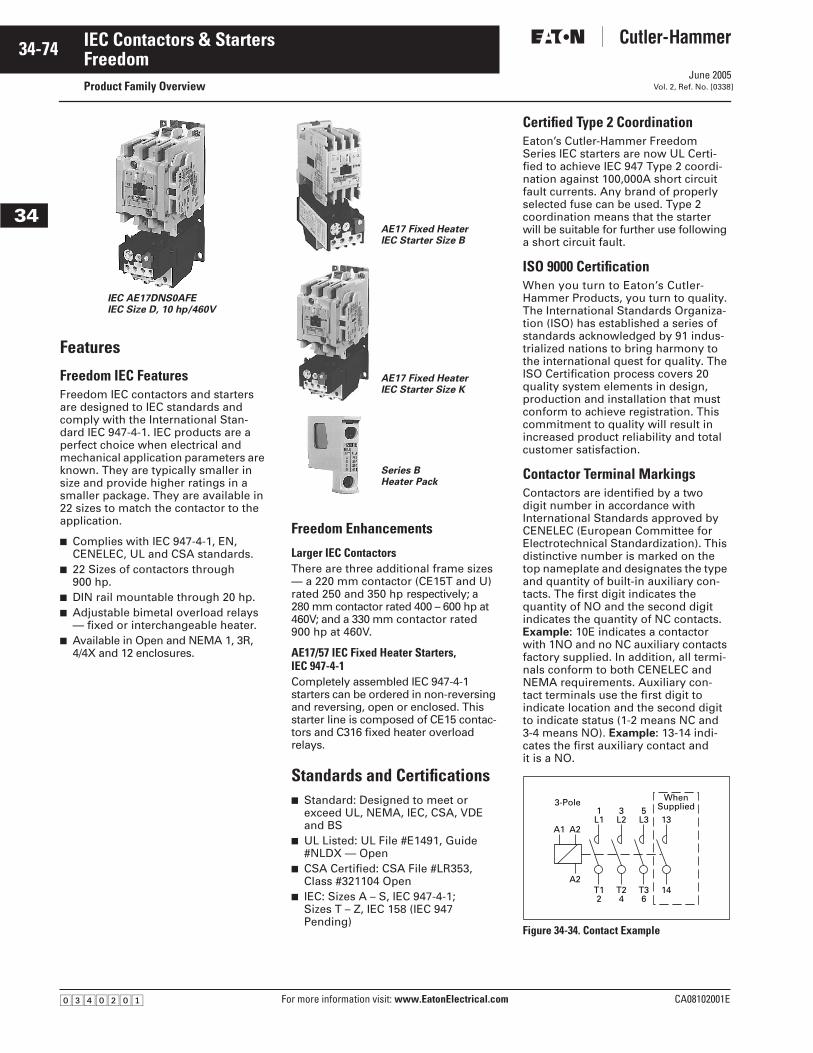
June 2005
34-74
For more information visit: www.EatonElectrical.com CA08102001E
IEC Contactors & Starters
34
FreedomProduct Family Overview Vol. 2, Ref. No. [0338]
Features
Freedom IEC FeaturesFreedom IEC contactors and starters are designed to IEC standards and comply with the International Stan-dard IEC 947-4-1. IEC products are a perfect choice when electrical and mechanical application parameters are known. They are typically smaller in size and provide higher ratings in a smaller package. They are available in 22 sizes to match the contactor to the application.
■ Complies with IEC 947-4-1, EN, CENELEC, UL and CSA standards.
■ 22 Sizes of contactors through 900 hp.
■ DIN rail mountable through 20 hp.■ Adjustable bimetal overload relays
— fixed or interchangeable heater.■ Available in Open and NEMA 1, 3R,
4/4X and 12 enclosures.
Freedom Enhancements
Larger IEC ContactorsThere are three additional frame sizes — a 220 mm contactor (CE15T and U) rated 250 and 350 hp respectively; a 280 mm contactor rated 400 – 600 hp at 460V; and a 330 mm contactor rated 900 hp at 460V.
AE17/57 IEC Fixed Heater Starters, IEC 947-4-1Completely assembled IEC 947-4-1 starters can be ordered in non-reversing and reversing, open or enclosed. This starter line is composed of CE15 contac-tors and C316 fixed heater overload relays.
Standards and Certifications■ Standard: Designed to meet or
exceed UL, NEMA, IEC, CSA, VDE and BS
■ UL Listed: UL File #E1491, Guide #NLDX — Open
■ CSA Certified: CSA File #LR353, Class #321104 Open
■ IEC: Sizes A – S, IEC 947-4-1; Sizes T – Z, IEC 158 (IEC 947 Pending)
Certified Type 2 CoordinationEaton’s Cutler-Hammer Freedom Series IEC starters are now UL Certi-fied to achieve IEC 947 Type 2 coordi-nation against 100,000A short circuit fault currents. Any brand of properly selected fuse can be used. Type 2 coordination means that the starter will be suitable for further use following a short circuit fault.
ISO 9000 CertificationWhen you turn to Eaton’s Cutler-Hammer Products, you turn to quality. The International Standards Organiza-tion (ISO) has established a series of standards acknowledged by 91 indus-trialized nations to bring harmony to the international quest for quality. The ISO Certification process covers 20 quality system elements in design, production and installation that must conform to achieve registration. This commitment to quality will result in increased product reliability and total customer satisfaction.
Contactor Terminal Markings Contactors are identified by a two digit number in accordance with International Standards approved by CENELEC (European Committee for Electrotechnical Standardization). This distinctive number is marked on the top nameplate and designates the type and quantity of built-in auxiliary con-tacts. The first digit indicates the quantity of NO and the second digit indicates the quantity of NC contacts. Example: 10E indicates a contactor with 1NO and no NC auxiliary contacts factory supplied. In addition, all termi-nals conform to both CENELEC and NEMA requirements. Auxiliary con-tact terminals use the first digit to indicate location and the second digit to indicate status (1-2 means NC and 3-4 means NO). Example: 13-14 indi-cates the first auxiliary contact and it is a NO.
Figure 34-34. Contact Example
IEC AE17DNS0AFEIEC Size D, 10 hp/460V
AE17 Fixed HeaterIEC Starter Size B
AE17 Fixed Heater IEC Starter Size K
Series BHeater Pack
A1 A2
A2
3-Pole1
L13
L25
L3 13
WhenSupplied
T12
T24
T36
14
�������
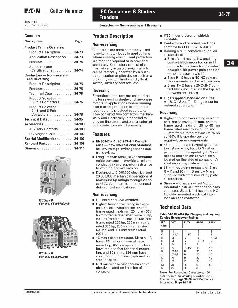
June 2005
CA08102001E For more information visit: www.EatonElectrical.com
34-75IEC Contactors & Starters
34
FreedomContactors — Non-reversing and ReversingVol. 2, Ref. No. [0339]
ContentsDescription Page
Product Family Overview
Product Description . . . . . . 34-73
Application Description . . . 34-73
Features . . . . . . . . . . . . . . . 34-74
Standards andCertifications . . . . . . . . . . 34-74
Contactors — Non-reversingand Reversing
Product Description . . . . . . 34-75
Features . . . . . . . . . . . . . . . 34-75
Technical Data . . . . . . . . . . 34-75
Product Selection —3-Pole Contactors . . . . . . 34-76
Product Selection —2-, 4- and 5-Pole Contactors . . . . . . . . . . . . 34-78
Technical Data . . . . . . . . . . . . . 34-95
Accessories . . . . . . . . . . . . . . . 34-100
Auxiliary Contacts . . . . . . . 34-100
DC Magnet Coils . . . . . . . . 34-102
Special Modifications . . . . . . . 34-107
Renewal Parts . . . . . . . . . . . . . 34-108
Dimensions . . . . . . . . . . . . . . . 34-114
Product Description
Non-reversing Contactors are most commonly used to switch motor loads in applications where running over current protection is either not required or is provided separately. Contactors consist of a magnetically actuated switch which can be remotely operated by a push-button station or pilot device such as a proximity switch, limit switch, float switch, auxiliary contacts, etc.
Reversing Reversing contactors are used prima-rily for reversing single- or three-phase motors in applications where running over current protection is either not required or is provided separately. They consist of two contactors mechan-ically and electrically interlocked to prevent line shorts and energization of both contactors simultaneously.
Features■ EN60947-4-1 IEC 947-4-1 Compli-
ance — new International Standard for low voltage switchgear and con-trol devices.
■ Long life twin break, silver cadmium oxide contacts — provide excellent conductivity and superior resistance to welding and arc erosion.
■ Designed to 2,000,000 electrical and 20,000,000 mechanical operations at maximum hp ratings through 20 hp at 460V. Adequate for most general duty control applications.
Non-reversing ■ UL listed and CSA certified.■ Highest horsepower rating in a com-
pact, space-saving design, 45 mm frame rated maximum 20 hp at 460V, 65 mm frame rated maximum 50 hp, 90 mm frame rated 100 hp, 180 mm frame rated 200 hp, 220 mm frame rated 350 hp, 280 mm frame rated 600 hp, and 334 mm frame rated 900 hp.
■ 45 mm open contactors, Sizes A – F, have DIN rail or universal base mounting, 65 mm open contactors have molded feet for panel mount-ing, and 90 mm to 334 mm have steel mounting plates (optional on smaller sizes).
■ DIN rail release mechanism conve-niently located on line side of contactor.
■ IP20 finger protection shields available.
■ Contactor and terminal markings conform to CENELEC EN50011.
■ Holding circuit contact(s) supplied as standard:❑ Sizes A – N have a NO auxiliary
contact block mounted on right hand side (on Sizes A – C, contact occupies 4th power pole position — no increase in width).
❑ Sizes P – S have a NO-NC contact block mounted on the left hand side.
❑ Sizes T – Z have a 2NO-2NC con-tact block mounted on the top left between arc chutes.
■ Lugs supplied standard on Sizes A – S. On Sizes T – Z, lugs must be ordered separately.
Reversing ■ Highest horsepower rating in a com-
pact, space-saving design, 45 mm frame rated maximum 20 hp, 65 mm frame rated maximum 50 hp and 90 mm frame rated maximum 75 hp at 460V. If larger devices are required, order components.
■ 45 mm open type reversing contac-tors, Sizes A – F, have DIN rail or panel mounting capability. DIN rail release mechanism conveniently located on line side of contactor. A steel mounting plate is optional.
■ 65 mm reversing contactors, Sizes G – K and 90 mm Sizes L – N are supplied with steel mounting plate as standard.
■ Sizes A – K have a wired NC top mounted electrical interlock on each contactor. Sizes L – N have one NO-NC side mounted electrical inter-lock on each contactor.
Technical DataTable 34-108. AC-4 (Ie) Plugging and Jogging Service Horsepower Ratings
Note: For Reversing Contactors, 100 – 400 hp, refer to Catalog Number CE15 Contactors, Page 34-76 and Mechanical Interlocks, Page 34-105.
IEC Size DCat. No. CE55DN3AB
IEC Size BCat. No. CE15BNS3AB
IECSize
200V 230V 460V 575V
BCDEF
11-1/2235
11-1/2235
2357-1/2
10
357-1/2
1015
GHJKL
57-1/27-1/2
1015
7-1/210101520
1520253040
2025304040
MN
2025
2530
5060
5075
�������
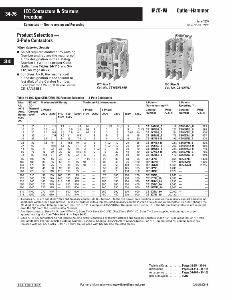
June 2005
34-76
For more information visit: www.EatonElectrical.com CA08102001E
IEC Contactors & Starters
34
FreedomContactors — Non-reversing and Reversing Vol. 2, Ref. No. [0340]
Product Selection — 3-Pole ContactorsWhen Ordering Specify■ Select required contactor by Catalog
Number and replace the magnet coil alpha designation in the Catalog Number (_) with the proper Code Suffix from Tables 34-110 and 34-112, on Page 34-77.
■ For Sizes A – K, the magnet coil alpha designation is the second-to-last digit of the Catalog Number. Example: for a 240V/60 Hz coil, order CE15ANS3BB.
Table 34-109. Type CE15/CE55 IEC Product Selection — 3-Pole Contactors
� IEC Sizes A – N are supplied with a NO auxiliary contact. On IEC Sizes A – C, the 4th power pole position is used as the auxiliary contact and adds no additional width. Open type Sizes A – K can be ordered with a top mounted auxiliary contact instead of a side mounted contact. To order, change the 7th digit of the listed Catalog Number from “S” to “T”. Example: CE15ANT3AB. On open type Sizes A – K, if the NO auxiliary contact is not required, drop the “S” from the listed Catalog Number.
� Auxiliary contacts: Sizes P – S have 1NO-1NC, Sizes T – X have 2NO-2NC, Size Z has 2NO-1NC. Sizes T – Z are supplied without lugs — order appropriate lug kits from Table 34-111 on Page 34-77.
� Sizes A – K IEC contactors do not include holding circuit contacts. For factory installed NO auxiliary contacts, insert “S” (side mounted) or “T” (top mounted) after 6th digit of listed Catalog Number. Example: Change CE55AN3AB to CE55ANS3AB. For “T”, top mounted NC contact blocks are replaced with NO-NC blocks — for “S”, they are replaced with NO-NC side mounted blocks.
IEC Size ECat. No. CE15ENS3AB
IEC Size NCat. No. CE15NN3A
Max.ULAC-3Amp.Rating600VAC
IEC 947AC-1ThermalCurrent600V
Maximum kW Rating Maximum UL Horsepower 3-Pole — Non-reversing ��
3-Pole —Reversing �
3-Phase 1-Phase 3-Phase CatalogNumber
PriceU.S. $
CatalogNumber
PriceU.S. $220V 380V 415/
440V500/550V
660V 115V 230V 200V 230V 460V 575V
710121825
2020203232
1.11.52.245.5
2.245.57.5
11
2.245.57.5
11
45.57.5
1115
1.52.245.57.5
1/41/21/2
12
1/21233
1-1/22355
1-1/22357-1/2
357-1/2
1015
57-1/2
101520
CE15ANS3_BCE15BNS3_BCE15CNS3_BCE15DNS3_BCE15ENS3_B
119.121.154.175.195.
CE55AN3_BCE55BN3_BCE55CN3_BCE55DN3_BCE55EN3_B
293.298.405.437.475.
3237446073
3250607580
7.5—111518.5
1518.5223037
1518.5223037
18.522303037
10111518.522
23355
557-1/2
1010
7-1/27-1/2
101520
1010152025
2025304050
2530404050
CE15FNS3_BCE15GNS3_BCE15HNS3_BCE15JNS3_BCE15KNS3_B
221.259.281.298.410.
CE55FN3_BCE55GN3_BCE55HN3_BCE55JN3_BCE55KN3_B
535.665.715.755.980.
85105140170200
100135175185220
2230374555
45557590
110
45557590
110
55759090
110
3745454555
7-1/21010——
101010——
2530405060
3040506075
6075
100125150
75100125125150
CE15LN3_CE15MN3_CE15NN3_CE15PN3_CE15RN3_
461.675.
1,065.1,490.1,670.
CE55LN3_CE55MN3_CE55NN3_——
1,470.1,925.2,715.
——
300420520550700
315600760
10001000
90129160220220
160220280375375
160240315——
160300375500500
75300375500500
—————
—————
75125150150200
100125150200250
200250350400500
200250350400500
CE15SN3_CE15TN3_80CE15UN3_80CE15VN3_80CE15WN3_80
2,260.2,760.4,930.7,260.8,500.
—————
—————
8101215
11001350
270380
475650
——
600840
600840
——
——
250450
300450
600900
600900
CE15XN3_80CE15ZN3_80
10,700.22,130.
——
——
Technical Data . . . . . . . . . . . Pages 34-95 – 34-99Dimensions . . . . . . . . . . . . . . Pages 34-114 – 34-121Accessories . . . . . . . . . . . . . Pages 34-100 – 34-107Discount Symbol . . . . . . . . . 1CD7
�������
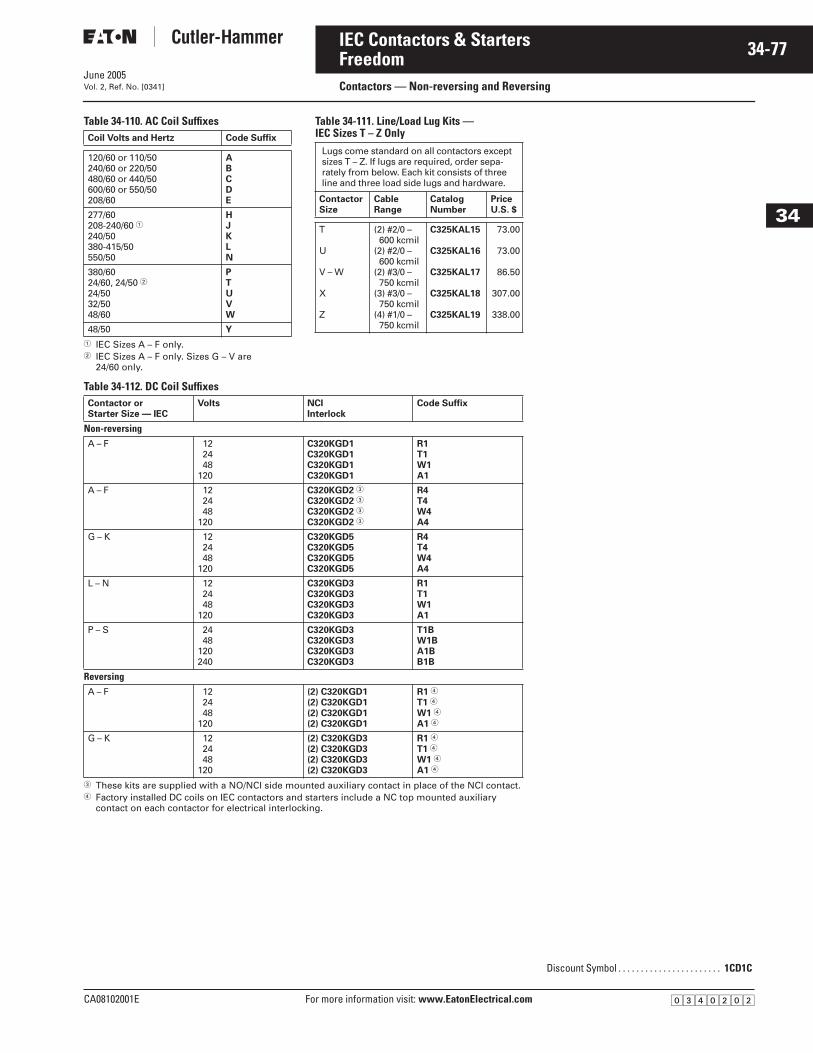
June 2005
CA08102001E For more information visit: www.EatonElectrical.com
34-77IEC Contactors & Starters
34
FreedomContactors — Non-reversing and ReversingVol. 2, Ref. No. [0341]
Table 34-110. AC Coil Suffixes
� IEC Sizes A – F only.� IEC Sizes A – F only. Sizes G – V are
24/60 only.
Table 34-111. Line/Load Lug Kits — IEC Sizes T – Z Only
Table 34-112. DC Coil Suffixes
� These kits are supplied with a NO/NCI side mounted auxiliary contact in place of the NCI contact.� Factory installed DC coils on IEC contactors and starters include a NC top mounted auxiliary
contact on each contactor for electrical interlocking.
Coil Volts and Hertz Code Suffix
120/60 or 110/50240/60 or 220/50480/60 or 440/50600/60 or 550/50208/60
ABCDE
277/60208-240/60 �240/50380-415/50550/50
HJKLN
380/6024/60, 24/50 �24/5032/5048/60
PTUVW
48/50 Y
Lugs come standard on all contactors except sizes T – Z. If lugs are required, order sepa-rately from below. Each kit consists of three line and three load side lugs and hardware.
ContactorSize
CableRange
CatalogNumber
PriceU.S. $
T
U
V – W
X
Z
(2) #2/0 – 600 kcmil
(2) #2/0 – 600 kcmil
(2) #3/0 – 750 kcmil
(3) #3/0 – 750 kcmil
(4) #1/0 – 750 kcmil
C325KAL15
C325KAL16
C325KAL17
C325KAL18
C325KAL19
73.00
73.00
86.50
307.00
338.00
Contactor orStarter Size — IEC
Volts NCIInterlock
Code Suffix
Non-reversingA – F 12
2448
120
C320KGD1C320KGD1C320KGD1C320KGD1
R1T1W1A1
A – F 122448
120
C320KGD2 �
C320KGD2 �
C320KGD2 �
C320KGD2 �
R4T4W4A4
G – K 122448
120
C320KGD5C320KGD5C320KGD5C320KGD5
R4T4W4A4
L – N 122448
120
C320KGD3C320KGD3C320KGD3C320KGD3
R1T1W1A1
P – S 2448
120240
C320KGD3C320KGD3C320KGD3C320KGD3
T1BW1BA1BB1B
ReversingA – F 12
2448
120
(2) C320KGD1(2) C320KGD1(2) C320KGD1(2) C320KGD1
R1 �
T1 �
W1 �
A1 �
G – K 122448
120
(2) C320KGD3(2) C320KGD3(2) C320KGD3(2) C320KGD3
R1 �
T1 �
W1 �
A1 �
Discount Symbol . . . . . . . . . . . . . . . . . . . . . . . 1CD1C
�������
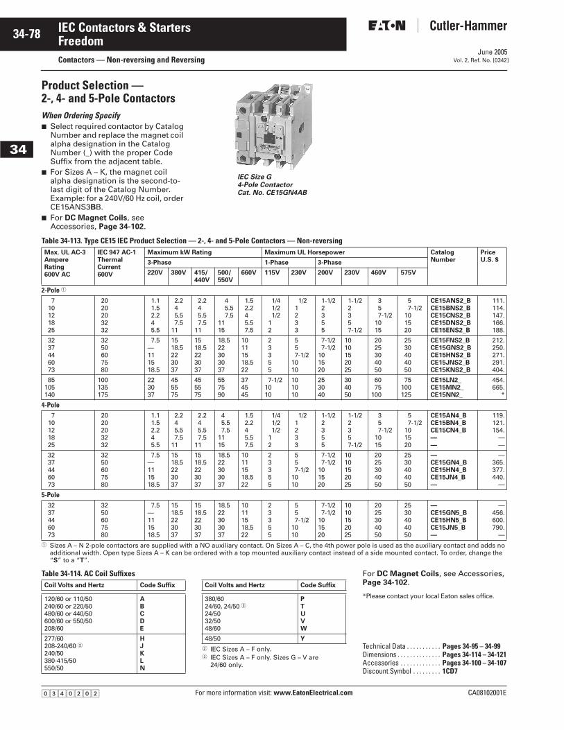
June 2005
34-78
For more information visit: www.EatonElectrical.com CA08102001E
IEC Contactors & Starters
34
FreedomContactors — Non-reversing and Reversing Vol. 2, Ref. No. [0342]
Product Selection — 2-, 4- and 5-Pole ContactorsWhen Ordering Specify ■ Select required contactor by Catalog
Number and replace the magnet coil alpha designation in the Catalog Number (_) with the proper Code Suffix from the adjacent table.
■ For Sizes A – K, the magnet coil alpha designation is the second-to-last digit of the Catalog Number. Example: for a 240V/60 Hz coil, order CE15ANS3BB.
■ For DC Magnet Coils, see Accessories, Page 34-102.
Table 34-113. Type CE15 IEC Product Selection — 2-, 4- and 5-Pole Contactors — Non-reversing
� Sizes A – N 2-pole contactors are supplied with a NO auxiliary contact. On Sizes A – C, the 4th power pole is used as the auxiliary contact and adds no additional width. Open type Sizes A – K can be ordered with a top mounted auxiliary contact instead of a side mounted contact. To order, change the “S” to a “T”.
Table 34-114. AC Coil Suffixes
� IEC Sizes A – F only.� IEC Sizes A – F only. Sizes G – V are
24/60 only.
For DC Magnet Coils, see Accessories, Page 34-102.
*Please contact your local Eaton sales office.
IEC Size G4-Pole ContactorCat. No. CE15GN4AB
Max. UL AC-3AmpereRating600V AC
IEC 947 AC-1ThermalCurrent600V
Maximum kW Rating Maximum UL Horsepower CatalogNumber
PriceU.S. $3-Phase 1-Phase 3-Phase
220V 380V 415/440V
500/550V
660V 115V 230V 200V 230V 460V 575V
2-Pole �
710121825
2020203232
1.11.52.245.5
2.245.57.5
11
2.245.57.5
11
45.57.5
1115
1.52.245.57.5
1/41/21/2
12
1/21233
1-1/22355
1-1/22357-1/2
357-1/2
1015
57-1/2
101520
CE15ANS2_BCE15BNS2_BCE15CNS2_BCE15DNS2_BCE15ENS2_B
111.114.147.166.188.
3237446073
3250607580
7.5—111518.5
1518.5223037
1518.5223037
18.522303037
10111518.522
23355
557-1/2
1010
7-1/27-1/2
101520
1010152025
2025304050
2530404050
CE15FNS2_BCE15GNS2_BCE15HNS2_BCE15JNS2_BCE15KNS2_B
212.250.271.291.404.
85105140
100135175
223037
455575
455575
557590
374545
7-1/21010
101010
253040
304050
6075
100
75100125
CE15LN2_CE15MN2_CE15NN2_
454.665.
*
4-Pole7
10121825
2020203232
1.11.52.245.5
2.245.57.5
11
2.245.57.5
11
45.57.5
1115
1.52.245.57.5
1/41/21/2
12
1/21233
1-1/22355
1-1/22357-1/2
357-1/2
1015
57-1/2
101520
CE15AN4_BCE15BN4_BCE15CN4_B——
119.121.154.
——
3237446073
3250607580
7.5—111518.5
1518.5223037
1518.5223037
18.522303037
10111518.522
23355
557-1/2
1010
7-1/27-1/2
101520
1010152025
2025304050
2530404050
—CE15GN4_BCE15HN4_BCE15JN4_B—
—365.377.440.
—
5-Pole3237446073
3250607580
7.5—111518.5
1518.5223037
1518.5223037
18.522303037
10111518.522
23355
557-1/2
1010
7-1/27-1/2
101520
1010152025
2025304050
2530404050
—CE15GN5_BCE15HN5_BCE15JN5_B—
—456.600.790.
—
Coil Volts and Hertz Code Suffix
120/60 or 110/50240/60 or 220/50480/60 or 440/50600/60 or 550/50208/60
ABCDE
277/60208-240/60 �240/50380-415/50550/50
HJKLN
Coil Volts and Hertz Code Suffix
380/6024/60, 24/50 �24/5032/5048/60
PTUVW
48/50 Y
Technical Data . . . . . . . . . . . Pages 34-95 – 34-99Dimensions . . . . . . . . . . . . . . Pages 34-114 – 34-121Accessories . . . . . . . . . . . . . Pages 34-100 – 34-107Discount Symbol . . . . . . . . . 1CD7
�������
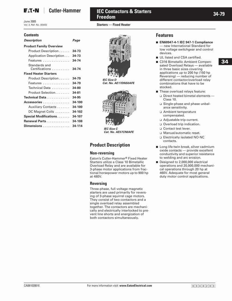
June 2005
CA08102001E For more information visit: www.EatonElectrical.com
34-79IEC Contactors & Starters
34
FreedomStarters — Fixed HeaterVol. 2, Ref. No. [0343]
ContentsDescription Page
Product Family Overview
Product Description . . . . . . 34-73
Application Description . . . 34-73
Features . . . . . . . . . . . . . . . 34-74
Standards andCertifications . . . . . . . . . . 34-74
Fixed Heater Starters
Product Description . . . . . . 34-79
Features . . . . . . . . . . . . . . . 34-79
Technical Data . . . . . . . . . . 34-80
Product Selection. . . . . . . . 34-81
Technical Data . . . . . . . . . . . . . 34-95
Accessories . . . . . . . . . . . . . . . 34-100
Auxiliary Contacts . . . . . . . 34-100
DC Magnet Coils . . . . . . . . 34-102
Special Modifications . . . . . . . 34-107
Renewal Parts . . . . . . . . . . . . . 34-108
Dimensions . . . . . . . . . . . . . . . 34-114
Product Description
Non-reversing Eaton’s Cutler-Hammer® Fixed Heater Starters utilize a Class 10 Bimetallic Overload Relay and are available for 3-phase motor applications from frac-tional horsepower motors up to 900 hp at 480V.
Reversing Three-phase, full voltage magnetic starters are used primarily for revers-ing of 3-phase squirrel cage motors. They consist of two contactors and a single overload relay assembled together. The contactors are mechani-cally and electrically interlocked to pre-vent line shorts and energization of both contactors simultaneously.
Features■ EN60947-4-1 IEC 947-1 Compliance
— new International Standard for low voltage switchgear and control devices.
■ UL listed and CSA certified.■ C316 Bimetallic Ambient Compen-
sated Overload Relays — available in three basic sizes covering applications up to 200 hp (150 hp Reversing) — reducing number of different contactor/overload relay combinations that have to be stocked.
■ These overload relays feature:❑ Direct heated bimetal elements —
Class 10.❑ Single-phase and phase unbal-
ance sensitivity.❑ Ambient temperature
compensated.❑ Adjustable trip current.❑ Overload trip indication.❑ Contact test lever.❑ Manual/automatic reset.❑ Electrically isolated NO-NC
contacts.
■ Long life twin break, silver cadmium oxide contacts — provide excellent conductivity and superior resistance to welding and arc erosion.
■ Designed to 2,000,000 electrical operations and 20,000,000 mechani-cal operations through 20 hp at 460V. Adequate for most general duty motor control applications.
IEC Size DCat. No. AE17DNS0AFE
IEC Size CCat. No. AE57CN0AFE
�������
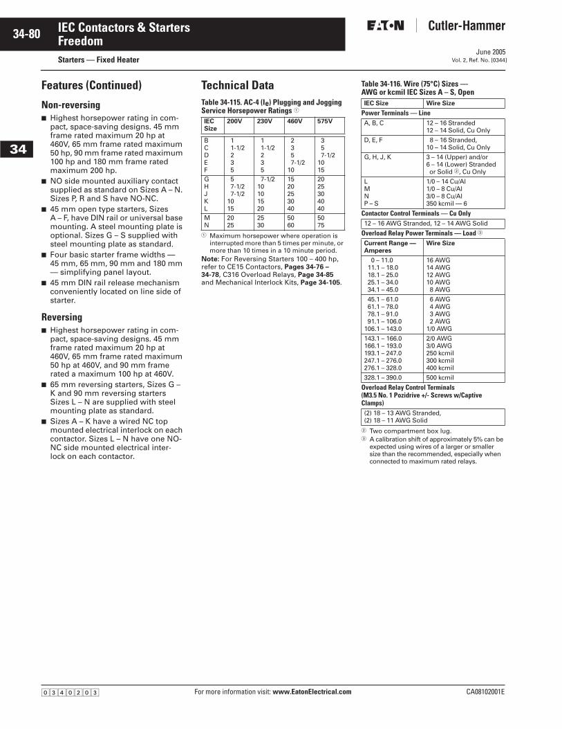
June 2005
34-80
For more information visit: www.EatonElectrical.com CA08102001E
IEC Contactors & Starters
34
FreedomStarters — Fixed Heater Vol. 2, Ref. No. [0344]
Features (Continued)
Non-reversing■ Highest horsepower rating in com-
pact, space-saving designs. 45 mm frame rated maximum 20 hp at 460V, 65 mm frame rated maximum 50 hp, 90 mm frame rated maximum 100 hp and 180 mm frame rated maximum 200 hp.
■ NO side mounted auxiliary contact supplied as standard on Sizes A – N. Sizes P, R and S have NO-NC.
■ 45 mm open type starters, Sizes A – F, have DIN rail or universal base mounting. A steel mounting plate is optional. Sizes G – S supplied with steel mounting plate as standard.
■ Four basic starter frame widths — 45 mm, 65 mm, 90 mm and 180 mm — simplifying panel layout.
■ 45 mm DIN rail release mechanism conveniently located on line side of starter.
Reversing■ Highest horsepower rating in com-
pact, space-saving designs. 45 mm frame rated maximum 20 hp at 460V, 65 mm frame rated maximum 50 hp at 460V, and 90 mm frame rated a maximum 100 hp at 460V.
■ 65 mm reversing starters, Sizes G – K and 90 mm reversing starters Sizes L – N are supplied with steel mounting plate as standard.
■ Sizes A – K have a wired NC top mounted electrical interlock on each contactor. Sizes L – N have one NO-NC side mounted electrical inter-lock on each contactor.
Technical DataTable 34-115. AC-4 (Ie) Plugging and Jogging Service Horsepower Ratings �
� Maximum horsepower where operation is interrupted more than 5 times per minute, or more than 10 times in a 10 minute period.
Note: For Reversing Starters 100 – 400 hp, refer to CE15 Contactors, Pages 34-76 – 34-78, C316 Overload Relays, Page 34-85 and Mechanical Interlock Kits, Page 34-105.
Table 34-116. Wire (75°C) Sizes —AWG or kcmil IEC Sizes A – S, Open
� Two compartment box lug.� A calibration shift of approximately 5% can be
expected using wires of a larger or smaller size than the recommended, especially when connected to maximum rated relays.
IECSize
200V 230V 460V 575V
BCDEF
11-1/2235
11-1/2235
2357-1/2
10
357-1/2
1015
GHJKL
57-1/27-1/2
1015
7-1/210101520
1520253040
2025304040
MN
2025
2530
5060
5075
IEC Size Wire Size
Power Terminals — LineA, B, C 12 – 16 Stranded
12 – 14 Solid, Cu Only
D, E, F 8 – 16 Stranded,10 – 14 Solid, Cu Only
G, H, J, K 3 – 14 (Upper) and/or6 – 14 (Lower) Strandedor Solid �, Cu Only
LMNP – S
1/0 – 14 Cu/Al1/0 – 8 Cu/Al3/0 – 8 Cu/Al350 kcmil — 6
Contactor Control Terminals — Cu Only12 – 16 AWG Stranded, 12 – 14 AWG Solid
Overload Relay Power Terminals — Load �
Current Range —Amperes
Wire Size
0 – 11.011.1 – 18.018.1 – 25.025.1 – 34.034.1 – 45.0
16 AWG14 AWG12 AWG10 AWG8 AWG
45.1 – 61.061.1 – 78.078.1 – 91.091.1 – 106.0
106.1 – 143.0
6 AWG4 AWG3 AWG2 AWG
1/0 AWG
143.1 – 166.0166.1 – 193.0193.1 – 247.0247.1 – 276.0276.1 – 328.0
2/0 AWG3/0 AWG250 kcmil300 kcmil400 kcmil
328.1 – 390.0 500 kcmil
Overload Relay Control Terminals(M3.5 No. 1 Pozidrive +/- Screws w/Captive Clamps)(2) 18 – 13 AWG Stranded, (2) 18 – 11 AWG Solid
�������
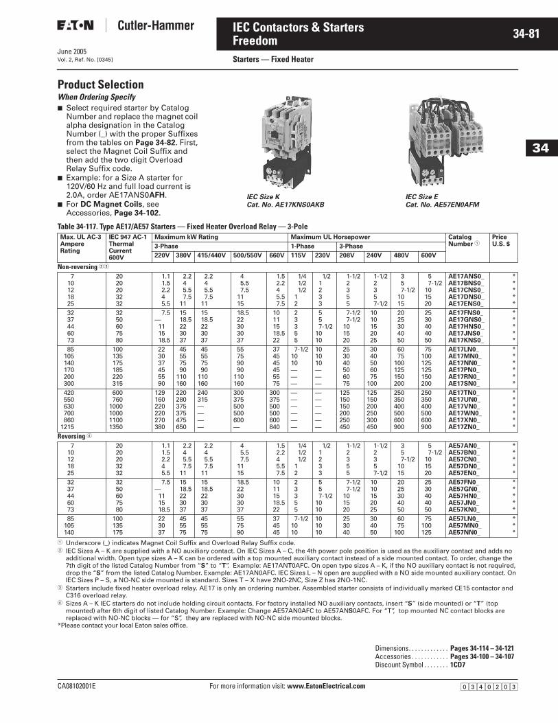
June 2005
CA08102001E For more information visit: www.EatonElectrical.com
34-81IEC Contactors & Starters
34
FreedomStarters — Fixed HeaterVol. 2, Ref. No. [0345]
Product SelectionWhen Ordering Specify ■ Select required starter by Catalog
Number and replace the magnet coil alpha designation in the Catalog Number (_) with the proper Suffixes from the tables on Page 34-82. First, select the Magnet Coil Suffix and then add the two digit Overload Relay Suffix code.
■ Example: for a Size A starter for 120V/60 Hz and full load current is 2.0A, order AE17ANS0AFH.
■ For DC Magnet Coils, see Accessories, Page 34-102.
Table 34-117. Type AE17/AE57 Starters — Fixed Heater Overload Relay — 3-Pole
� Underscore (_) indicates Magnet Coil Suffix and Overload Relay Suffix code.� IEC Sizes A – K are supplied with a NO auxiliary contact. On IEC Sizes A – C, the 4th power pole position is used as the auxiliary contact and adds no
additional width. Open type sizes A – K can be ordered with a top mounted auxiliary contact instead of a side mounted contact. To order, change the 7th digit of the listed Catalog Number from “S” to “T”. Example: AE17ANT0AFC. On open type sizes A – K, if the NO auxiliary contact is not required, drop the “S” from the listed Catalog Number. Example: AE17AN0AFC. IEC Sizes L – N open are supplied with a NO side mounted auxiliary contact. On IEC Sizes P – S, a NO-NC side mounted is standard. Sizes T – X have 2NO-2NC, Size Z has 2NO-1NC.
� Starters include fixed heater overload relay. AE17 is only an ordering number. Assembled starter consists of individually marked CE15 contactor and C316 overload relay.
� Sizes A – K IEC starters do not include holding circuit contacts. For factory installed NO auxiliary contacts, insert “S” (side mounted) or “T” (top mounted) after 6th digit of listed Catalog Number. Example: Change AE57AN0AFC to AE57ANS0AFC. For “T”, top mounted NC contact blocks are replaced with NO-NC blocks — for “S”, they are replaced with NO-NC side mounted blocks.
*Please contact your local Eaton sales office.
IEC Size KCat. No. AE17KNS0AKB
IEC Size ECat. No. AE57EN0AFM
Max. UL AC-3AmpereRating
IEC 947 AC-1ThermalCurrent600V
Maximum kW Rating Maximum UL Horsepower CatalogNumber �
PriceU.S. $3-Phase 1-Phase 3-Phase
220V 380V 415/440V 500/550V 660V 115V 230V 208V 240V 480V 600V
Non-reversing ��
710121825
2020203232
1.11.52.245.5
2.245.57.5
11
2.245.57.5
11
45.57.5
1115
1.52.245.57.5
1/41/21/2
12
1/21233
1-1/22355
1-1/22357-1/2
357-1/2
1015
57-1/2
101520
AE17ANS0_AE17BNS0_AE17CNS0_AE17DNS0_AE17ENS0_
*****
3237446073
3250607580
7.5—111518.5
1518.5223037
1518.5223037
18.522303037
10111518.522
23355
557-1/2
1010
7-1/27-1/2
101520
1010152025
2025304050
2530404050
AE17FNS0_AE17GNS0_AE17HNS0_AE17JNS0_AE17KNS0_
*****
85105140170200300
100135175185220315
223037455590
45557590
110160
45557590
110160
55759090
110160
374545455575
7-1/21010———
101010———
253040506075
3040506075
100
6075
100125150200
75100125125150200
AE17LN0_AE17MN0_AE17NN0_AE17PN0_AE17RN0_AE17SN0_
******
420550630700860
1215
600760
1000100011001350
129160220220270380
220280375375475650
240315————
300375500500600—
300375500500600840
——————
——————
125150150200250450
125150200250300450
250350400500600900
250350400500600900
AE17TN0_AE17UN0_AE17VN0_AE17WN0_AE17XN0_AE17ZN0_
******
Reversing �
710121825
2020203232
1.11.52.245.5
2.245.57.5
11
2.245.57.5
11
45.57.5
1115
1.52.245.57.5
1/41/21/2
12
1/21233
1-1/22355
1-1/22357-1/2
357-1/2
1015
57-1/2
101520
AE57AN0_AE57BN0_AE57CN0_AE57DN0_AE57EN0_
*****
3237446073
3250607580
7.5—111518.5
1518.5223037
1518.5223037
18.522303037
10111518.522
23355
557-1/2
1010
7-1/27-1/2
101520
1010152025
2025304050
2530404050
AE57FN0_AE57GN0_AE57HN0_AE57JN0_AE57KN0_
*****
85105140
100135175
223037
455575
455575
557590
374545
7-1/21010
101010
253040
304050
6075
100
75100125
AE57LN0_AE57MN0_AE57NN0_
***
Dimensions. . . . . . . . . . . . . Pages 34-114 – 34-121Accessories . . . . . . . . . . . . Pages 34-100 – 34-107Discount Symbol . . . . . . . . 1CD7
�������
June 2005
34-82
For more information visit: www.EatonElectrical.com CA08102001E
IEC Contactors & Starters
34
FreedomStarters — Fixed Heater Vol. 2, Ref. No. [0346]
Table 34-118. Maximum Horsepower Rating of Starters for 380V 50 Hz Application
Table 34-119. AC Coil Suffixes
� IEC Sizes A – F only.� IEC Sizes A – F only. Sizes G – V are
24/60 only.
For DC Magnet Coils, see Accessories, Page 34-102.
Table 34-120. Fixed Heater Overload Relay Suffix Codes �
� Overload relay range can not exceed contac-tor ampere rating.
IEC Size A B C D E F G H J K L M N P R S
hp 3 5 5 10 10 15 20 25 30 40 50 60 75 100 125 150
Coil Volts and Hertz Code Suffix
120/60 or 110/50240/60 or 220/50480/60 or 440/50600/60 or 550/50208/60
ABCDE
277/60208-240/60 �240/50380-415/50550/50
HJKLN
24/60, 24/50 �24/5032/5048/6048/50
TUVWY
Motor FullLoad Amperes
SuffixLetter
Motor FullLoad Amperes
SuffixLetter
Sizes AE17A – AE17F.25 – .40.40 – .63.63 – 1.0
1.0 – 1.41.3 – 1.8
FCFDFEFFFG
3.5 – 5.04.5 – 6.56.0 – 8.57.5 – 11
10 – 14
FLFMFNFPFQ
1.7 – 2.42.2 – 3.12.8 – 4.0
FHFJFK
13 – 1918 – 2424 – 32
FRFSFT
Sizes AE17G – AE17K18 – 2522 – 3229 – 42
KAKBKC
36 – 5245 – 6360 – 80
KDKEKF
Sizes AE17L – AE17N65 – 9080 – 100
100 – 135
PAPBPC
110 – 150130 – 175
—
PDPE—
Sizes AE17P – AE17S with 300/5 CT60 – 8478 – 108
102 – 144
FFFGFH
132 – 186168 – 240210 – 300
FJFKFL
Sizes AE17T – AE17V with 600/5 CT120 – 168156 – 216204 – 288
FFFGFH
264 – 372336 – 480420 – 600
FJFKFL
Sizes AE17W – AE17X with 1000/5 CT200 – 280260 – 360340 – 480
FFFGFH
440 – 620560 – 800700 – 1000
FJFKFL
Size AE17Z with 1500/5 CT300 – 420390 – 540510 – 720
FHFGFH
660 – 930840 – 1200
1050 – 1500
FJFKFL
�������
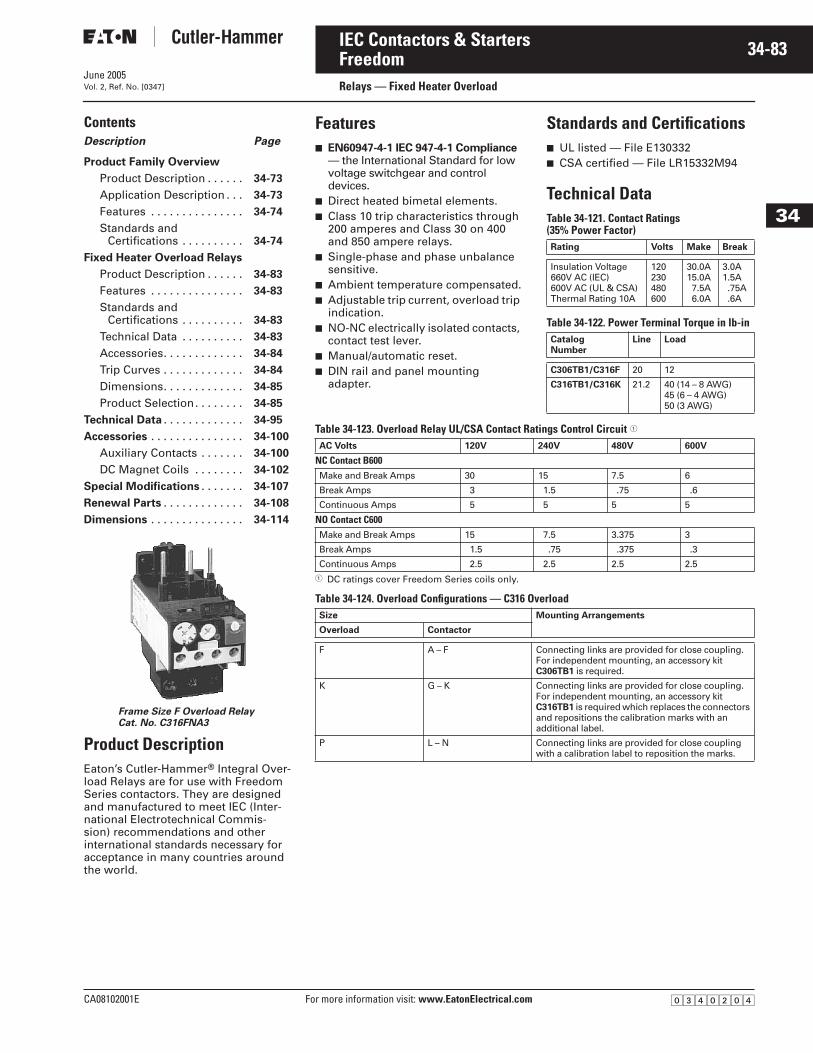
June 2005
CA08102001E For more information visit: www.EatonElectrical.com
34-83IEC Contactors & Starters
34
Freedom Relays — Fixed Heater OverloadVol. 2, Ref. No. [0347]
Contents Description Page
Product Family Overview
Product Description . . . . . . 34-73
Application Description . . . 34-73
Features . . . . . . . . . . . . . . . 34-74
Standards andCertifications . . . . . . . . . . 34-74
Fixed Heater Overload Relays
Product Description . . . . . . 34-83
Features . . . . . . . . . . . . . . . 34-83
Standards and Certifications . . . . . . . . . . 34-83
Technical Data . . . . . . . . . . 34-83
Accessories. . . . . . . . . . . . . 34-84
Trip Curves . . . . . . . . . . . . . 34-84
Dimensions. . . . . . . . . . . . . 34-85
Product Selection. . . . . . . . 34-85
Technical Data . . . . . . . . . . . . . 34-95
Accessories . . . . . . . . . . . . . . . 34-100
Auxiliary Contacts . . . . . . . 34-100
DC Magnet Coils . . . . . . . . 34-102
Special Modifications . . . . . . . 34-107
Renewal Parts . . . . . . . . . . . . . 34-108
Dimensions . . . . . . . . . . . . . . . 34-114
Product DescriptionEaton’s Cutler-Hammer® Integral Over-load Relays are for use with Freedom Series contactors. They are designed and manufactured to meet IEC (Inter-national Electrotechnical Commis-sion) recommendations and other international standards necessary for acceptance in many countries around the world.
Frame Size F Overload RelayCat. No. C316FNA3
Features■ EN60947-4-1 IEC 947-4-1 Compliance
— the International Standard for low voltage switchgear and control devices.
■ Direct heated bimetal elements.■ Class 10 trip characteristics through
200 amperes and Class 30 on 400 and 850 ampere relays.
■ Single-phase and phase unbalance sensitive.
■ Ambient temperature compensated.■ Adjustable trip current, overload trip
indication.■ NO-NC electrically isolated contacts,
contact test lever.■ Manual/automatic reset.■ DIN rail and panel mounting
adapter.
Standards and Certifications■ UL listed — File E130332■ CSA certified — File LR15332M94
Technical DataTable 34-121. Contact Ratings(35% Power Factor)
Table 34-122. Power Terminal Torque in lb-in
Table 34-123. Overload Relay UL/CSA Contact Ratings Control Circuit �
� DC ratings cover Freedom Series coils only.
Table 34-124. Overload Configurations — C316 Overload
Rating Volts Make Break
Insulation Voltage660V AC (IEC)600V AC (UL & CSA)Thermal Rating 10A
120230480600
30.0A15.0A7.5A6.0A
3.0A1.5A.75A.6A
CatalogNumber
Line Load
C306TB1/C316F 20 12
C316TB1/C316K 21.2 40 (14 – 8 AWG)45 (6 – 4 AWG)50 (3 AWG)
AC Volts 120V 240V 480V 600V
NC Contact B600Make and Break Amps 30 15 7.5 6
Break Amps 3 1.5 .75 .6
Continuous Amps 5 5 5 5
NO Contact C600Make and Break Amps 15 7.5 3.375 3
Break Amps 1.5 .75 .375 .3
Continuous Amps 2.5 2.5 2.5 2.5
Size Mounting Arrangements
Overload Contactor
F A – F Connecting links are provided for close coupling. For independent mounting, an accessory kit C306TB1 is required.
K G – K Connecting links are provided for close coupling. For independent mounting, an accessory kit C316TB1 is required which replaces the connectors and repositions the calibration marks with an additional label.
P L – N Connecting links are provided for close coupling with a calibration label to reposition the marks.
�������
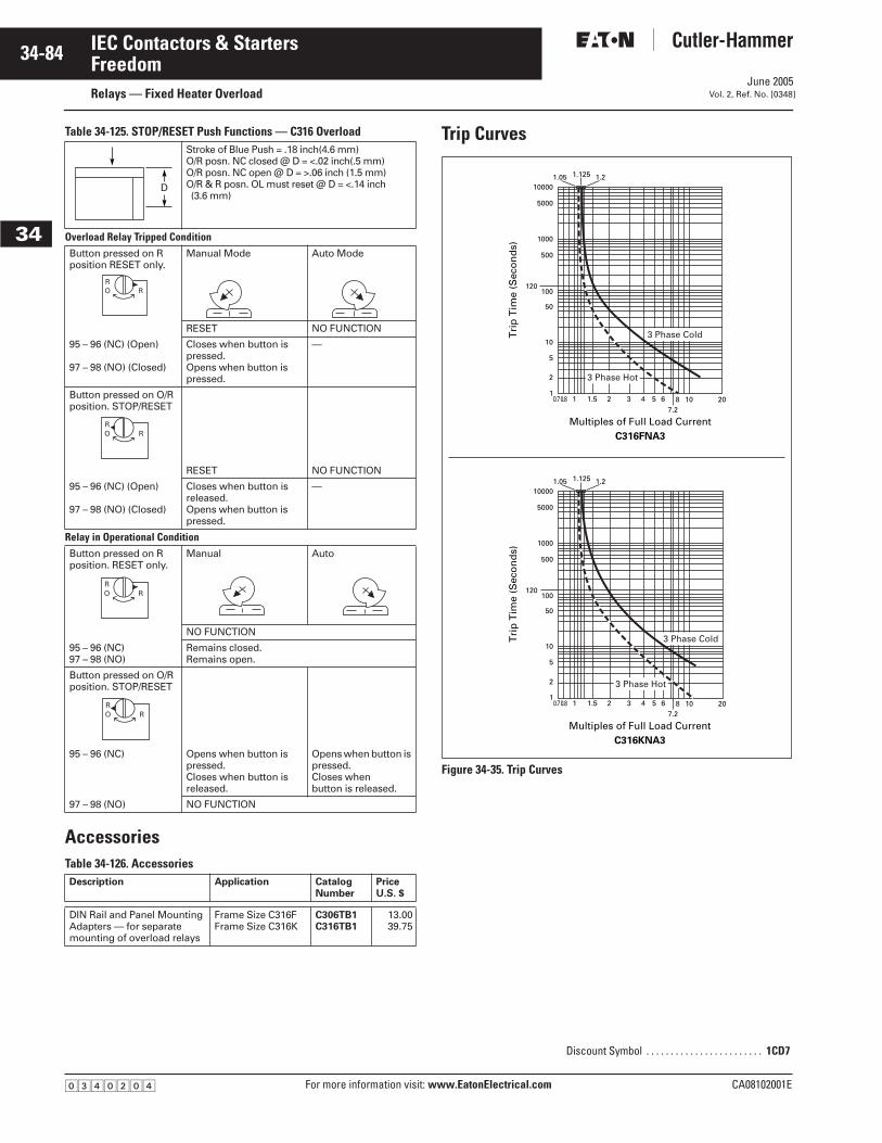
June 2005
34-84
For more information visit: www.EatonElectrical.com CA08102001E
IEC Contactors & Starters
34
FreedomRelays — Fixed Heater Overload Vol. 2, Ref. No. [0348]
Table 34-125. STOP/RESET Push Functions — C316 Overload
AccessoriesTable 34-126. Accessories
Trip Curves
Figure 34-35. Trip Curves
Stroke of Blue Push = .18 inch(4.6 mm)O/R posn. NC closed @ D = <.02 inch(.5 mm)O/R posn. NC open @ D = >.06 inch (1.5 mm)O/R & R posn. OL must reset @ D = <.14 inch (3.6 mm)
Overload Relay Tripped ConditionButton pressed on R position RESET only.
Manual Mode Auto Mode
RESET NO FUNCTION
95 – 96 (NC) (Open)
97 – 98 (NO) (Closed)
Closes when button is pressed.Opens when button is pressed.
—
Button pressed on O/R position. STOP/RESET
RESET NO FUNCTION
95 – 96 (NC) (Open)
97 – 98 (NO) (Closed)
Closes when button is released. Opens when button is pressed.
—
Relay in Operational ConditionButton pressed on R position. RESET only.
Manual Auto
NO FUNCTION
95 – 96 (NC)97 – 98 (NO)
Remains closed.Remains open.
Button pressed on O/R position. STOP/RESET
95 – 96 (NC) Opens when button is pressed. Closes when button is released.
Opens when button is pressed.Closes when button is released.
97 – 98 (NO) NO FUNCTION
Description Application CatalogNumber
PriceU.S. $
DIN Rail and Panel Mounting Adapters — for separate mounting of overload relays
Frame Size C316FFrame Size C316K
C306TB1C316TB1
13.0039.75
D
ROR
ROR
ROR
ROR
Discount Symbol . . . . . . . . . . . . . . . . . . . . . . . . 1CD7
0.70.8 1 1.5
1.05 1.125 1.2
2 3 4 5 67.2
8 10 20
Multiples of Full Load CurrentC316FNA3
Tri
p T
ime
(Sec
on
ds)
3 Phase Cold
3 Phase Hot
10000
5000
1000
500
100120
50
10
5
1
2
Multiples of Full Load CurrentC316KNA3
0.70.8 1 1.5
1.05 1.125 1.2
2 3 4 5 67.2
8 10 20
Tri
p T
ime
(Sec
on
ds)
3 Phase Cold
3 Phase Hot
10000
5000
1000
500
100120
50
10
5
1
2
�������
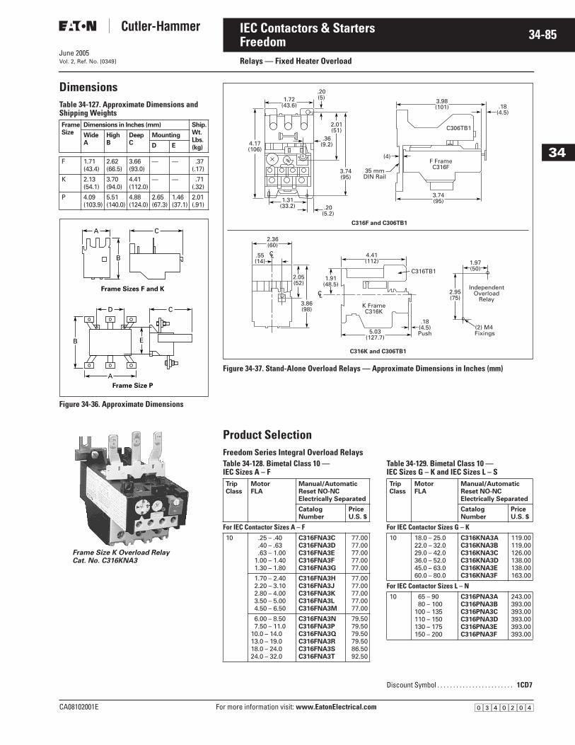
June 2005
CA08102001E For more information visit: www.EatonElectrical.com
34-85IEC Contactors & Starters
34
Freedom Relays — Fixed Heater Overload Vol. 2, Ref. No. [0349]
DimensionsTable 34-127. Approximate Dimensions andShipping Weights
Figure 34-36. Approximate Dimensions
FrameSize
Dimensions in Inches (mm) Ship.Wt.Lbs.(kg)
WideA
HighB
DeepC
Mounting
D E
F 1.71(43.4)
2.62(66.5)
3.66(93.0)
— — .37(.17)
K 2.13(54.1)
3.70(94.0)
4.41(112.0)
— — .71(.32)
P 4.09(103.9)
5.51(140.0)
4.88(124.0)
2.65(67.3)
1.46(37.1)
2.01(.91)
B
A C
D C
E
Frame Size P
Frame Sizes F and K
B
A
Frame Size K Overload RelayCat. No. C316KNA3
Figure 34-37. Stand-Alone Overload Relays — Approximate Dimensions in Inches (mm)
Product Selection Freedom Series Integral Overload RelaysTable 34-128. Bimetal Class 10 — IEC Sizes A – F
Table 34-129. Bimetal Class 10 — IEC Sizes G – K and IEC Sizes L – S
.36(9.2)4.17
(106)
1.72(43.6)
1.31(33.2) .20
(5.2)
(4)
.20(5)
2.01(51)
3.98(101)
3.74(95)
.18(4.5)
3.74(95)
C316F and C306TB1
C306TB1
F FrameC316F
35 mmDIN Rail
3.86(98)
2.05(52)
1.91(48.5)
2.36(60)
4.41(112) 1.97
(50)
5.03(127.7)
.18(4.5)Push
.55(14)
2.95(75)
IndependentOverload
Relay
C316TB1
K FrameC316K
(2) M4 Fixings
C L
C L
C316K and C306TB1
TripClass
MotorFLA
Manual/Automatic Reset NO-NC Electrically Separated
CatalogNumber
PriceU.S. $
For IEC Contactor Sizes A – F10 .25 – .40
.40 – .63
.63 – 1.001.00 – 1.401.30 – 1.80
C316FNA3CC316FNA3DC316FNA3EC316FNA3FC316FNA3G
77.0077.0077.0077.0077.00
1.70 – 2.402.20 – 3.102.80 – 4.003.50 – 5.004.50 – 6.50
C316FNA3HC316FNA3JC316FNA3KC316FNA3LC316FNA3M
77.0077.0077.0077.0077.00
6.00 – 8.507.50 – 11.0
10.0 – 14.013.0 – 19.018.0 – 24.024.0 – 32.0
C316FNA3NC316FNA3PC316FNA3QC316FNA3RC316FNA3SC316FNA3T
79.5079.5079.5079.5086.5092.50
TripClass
MotorFLA
Manual/Automatic Reset NO-NC Electrically Separated
CatalogNumber
PriceU.S. $
For IEC Contactor Sizes G – K10 18.0 – 25.0
22.0 – 32.029.0 – 42.036.0 – 52.045.0 – 63.060.0 – 80.0
C316KNA3AC316KNA3BC316KNA3CC316KNA3DC316KNA3EC316KNA3F
119.00119.00126.00138.00138.00163.00
For IEC Contactor Sizes L – N10 65 – 90
80 – 100100 – 135110 – 150130 – 175150 – 200
C316PNA3AC316PNA3BC316PNA3CC316PNA3DC316PNA3EC316PNA3F
243.00393.00393.00393.00393.00393.00
Discount Symbol . . . . . . . . . . . . . . . . . . . . . . . . 1CD7
�������
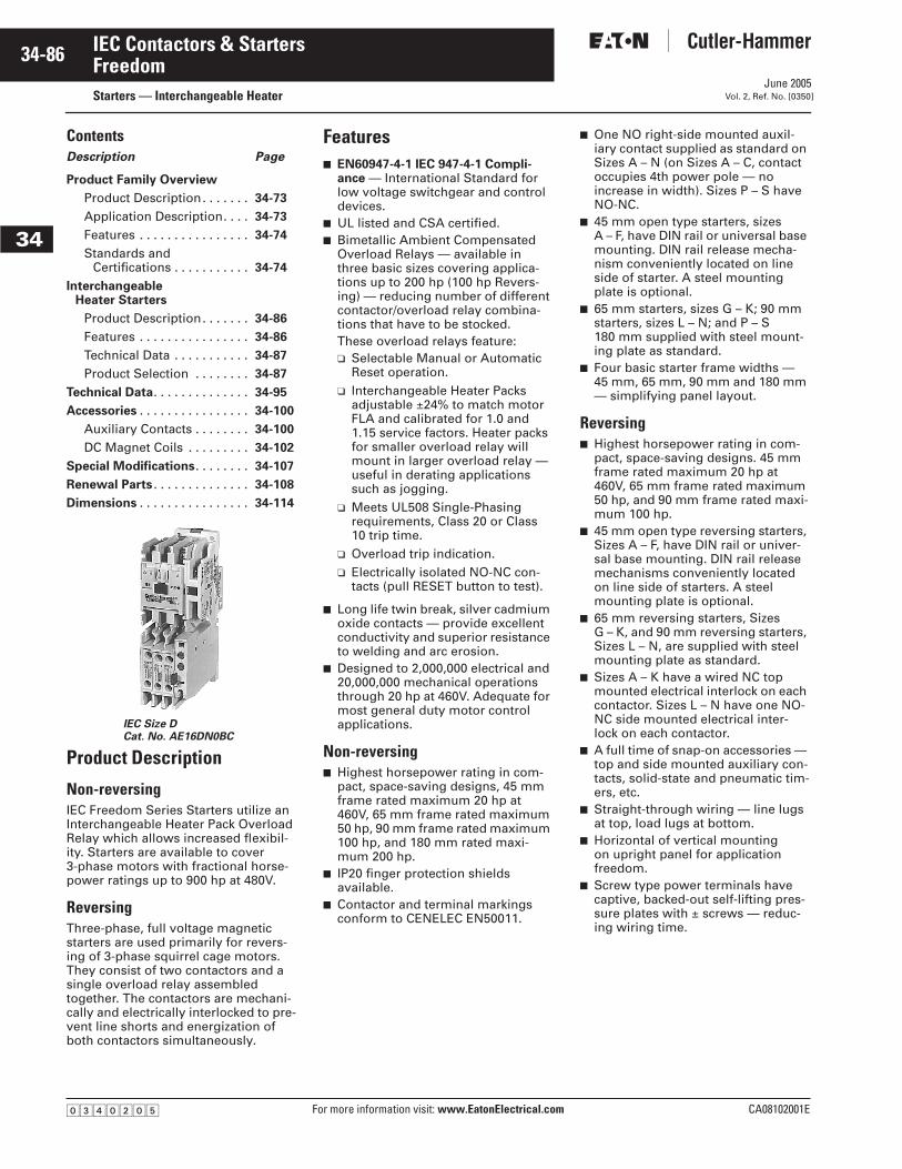
June 2005
34-86
For more information visit: www.EatonElectrical.com CA08102001E
IEC Contactors & Starters
34
FreedomStarters — Interchangeable Heater Vol. 2, Ref. No. [0350]
ContentsDescription Page
Product Family Overview
Product Description. . . . . . . 34-73
Application Description. . . . 34-73
Features . . . . . . . . . . . . . . . . 34-74
Standards andCertifications . . . . . . . . . . . 34-74
Interchangeable Heater Starters
Product Description. . . . . . . 34-86
Features . . . . . . . . . . . . . . . . 34-86
Technical Data . . . . . . . . . . . 34-87
Product Selection . . . . . . . . 34-87
Technical Data. . . . . . . . . . . . . . 34-95
Accessories . . . . . . . . . . . . . . . . 34-100
Auxiliary Contacts . . . . . . . . 34-100
DC Magnet Coils . . . . . . . . . 34-102
Special Modifications. . . . . . . . 34-107
Renewal Parts . . . . . . . . . . . . . . 34-108
Dimensions . . . . . . . . . . . . . . . . 34-114
Product Description
Non-reversing IEC Freedom Series Starters utilize an Interchangeable Heater Pack Overload Relay which allows increased flexibil-ity. Starters are available to cover 3-phase motors with fractional horse-power ratings up to 900 hp at 480V.
Reversing Three-phase, full voltage magnetic starters are used primarily for revers-ing of 3-phase squirrel cage motors. They consist of two contactors and a single overload relay assembled together. The contactors are mechani-cally and electrically interlocked to pre-vent line shorts and energization of both contactors simultaneously.
Features■ EN60947-4-1 IEC 947-4-1 Compli-
ance — International Standard for low voltage switchgear and control devices.
■ UL listed and CSA certified.■ Bimetallic Ambient Compensated
Overload Relays — available in three basic sizes covering applica-tions up to 200 hp (100 hp Revers-ing) — reducing number of different contactor/overload relay combina-tions that have to be stocked.These overload relays feature:❑ Selectable Manual or Automatic
Reset operation.❑ Interchangeable Heater Packs
adjustable ±24% to match motor FLA and calibrated for 1.0 and 1.15 service factors. Heater packs for smaller overload relay will mount in larger overload relay — useful in derating applications such as jogging.
❑ Meets UL508 Single-Phasing requirements, Class 20 or Class 10 trip time.
❑ Overload trip indication.❑ Electrically isolated NO-NC con-
tacts (pull RESET button to test).
■ Long life twin break, silver cadmium oxide contacts — provide excellent conductivity and superior resistance to welding and arc erosion.
■ Designed to 2,000,000 electrical and 20,000,000 mechanical operations through 20 hp at 460V. Adequate for most general duty motor control applications.
Non-reversing■ Highest horsepower rating in com-
pact, space-saving designs, 45 mm frame rated maximum 20 hp at 460V, 65 mm frame rated maximum 50 hp, 90 mm frame rated maximum 100 hp, and 180 mm rated maxi-mum 200 hp.
■ IP20 finger protection shields available.
■ Contactor and terminal markings conform to CENELEC EN50011.
■ One NO right-side mounted auxil-iary contact supplied as standard on Sizes A – N (on Sizes A – C, contact occupies 4th power pole — no increase in width). Sizes P – S have NO-NC.
■ 45 mm open type starters, sizes A – F, have DIN rail or universal base mounting. DIN rail release mecha-nism conveniently located on line side of starter. A steel mounting plate is optional.
■ 65 mm starters, sizes G – K; 90 mm starters, sizes L – N; and P – S 180 mm supplied with steel mount-ing plate as standard.
■ Four basic starter frame widths — 45 mm, 65 mm, 90 mm and 180 mm — simplifying panel layout.
Reversing■ Highest horsepower rating in com-
pact, space-saving designs. 45 mm frame rated maximum 20 hp at 460V, 65 mm frame rated maximum 50 hp, and 90 mm frame rated maxi-mum 100 hp.
■ 45 mm open type reversing starters, Sizes A – F, have DIN rail or univer-sal base mounting. DIN rail release mechanisms conveniently located on line side of starters. A steel mounting plate is optional.
■ 65 mm reversing starters, Sizes G – K, and 90 mm reversing starters, Sizes L – N, are supplied with steel mounting plate as standard.
■ Sizes A – K have a wired NC top mounted electrical interlock on each contactor. Sizes L – N have one NO-NC side mounted electrical inter-lock on each contactor.
■ A full time of snap-on accessories — top and side mounted auxiliary con-tacts, solid-state and pneumatic tim-ers, etc.
■ Straight-through wiring — line lugs at top, load lugs at bottom.
■ Horizontal of vertical mounting on upright panel for application freedom.
■ Screw type power terminals have captive, backed-out self-lifting pres-sure plates with ± screws — reduc-ing wiring time.
IEC Size DCat. No. AE16DN0BC
�������
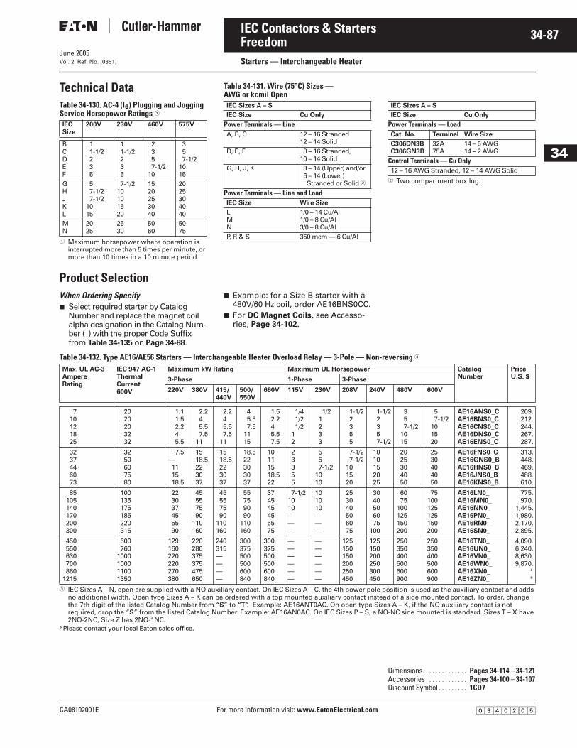
June 2005
CA08102001E For more information visit: www.EatonElectrical.com
34-87IEC Contactors & Starters
34
FreedomStarters — Interchangeable Heater Vol. 2, Ref. No. [0351]
Technical DataTable 34-130. AC-4 (Ie) Plugging and Jogging Service Horsepower Ratings �
� Maximum horsepower where operation is interrupted more than 5 times per minute, or more than 10 times in a 10 minute period.
Table 34-131. Wire (75°C) Sizes — AWG or kcmil Open
� Two compartment box lug.
Product SelectionWhen Ordering Specify ■ Select required starter by Catalog
Number and replace the magnet coil alpha designation in the Catalog Num-ber (_) with the proper Code Suffix from Table 34-135 on Page 34-88.
■ Example: for a Size B starter with a 480V/60 Hz coil, order AE16BNS0CC.
■ For DC Magnet Coils, see Accesso-ries, Page 34-102.
Table 34-132. Type AE16/AE56 Starters — Interchangeable Heater Overload Relay — 3-Pole — Non-reversing �
� IEC Sizes A – N, open are supplied with a NO auxiliary contact. On IEC Sizes A – C, the 4th power pole position is used as the auxiliary contact and adds no additional width. Open type Sizes A – K can be ordered with a top mounted auxiliary contact instead of a side mounted contact. To order, change the 7th digit of the listed Catalog Number from “S” to “T”. Example: AE16ANT0AC. On open type Sizes A – K, if the NO auxiliary contact is not required, drop the “S” from the listed Catalog Number. Example: AE16AN0AC. On IEC Sizes P – S, a NO-NC side mounted is standard. Sizes T – X have 2NO-2NC, Size Z has 2NO-1NC.
*Please contact your local Eaton sales office.
IECSize
200V 230V 460V 575V
BCDEF
11-1/2235
11-1/2235
2357-1/2
10
357-1/2
1015
GHJKL
57-1/27-1/2
1015
7-1/210101520
1520253040
2025304040
MN
2025
2530
5060
5075
IEC Sizes A – S
IEC Size Cu Only
Power Terminals — LineA, B, C 12 – 16 Stranded
12 – 14 SolidD, E, F 8 – 16 Stranded,
10 – 14 SolidG, H, J, K 3 – 14 (Upper) and/or
6 – 14 (Lower)Stranded or Solid �
Power Terminals — Line and LoadIEC Size Wire Size
LMN
1/0 – 14 Cu/Al1/0 – 8 Cu/Al3/0 – 8 Cu/Al
P, R & S 350 mcm — 6 Cu/Al
IEC Sizes A – S
IEC Size Cu Only
Power Terminals — LoadCat. No. Terminal Wire Size
C306DN3BC306GN3B
32A75A
14 – 6 AWG14 – 2 AWG
Control Terminals — Cu Only12 – 16 AWG Stranded, 12 – 14 AWG Solid
Max. UL AC-3AmpereRating
IEC 947 AC-1ThermalCurrent600V
Maximum kW Rating Maximum UL Horsepower CatalogNumber
PriceU.S. $3-Phase 1-Phase 3-Phase
220V 380V 415/440V
500/550V
660V 115V 230V 208V 240V 480V 600V
710121825
2020203232
1.11.52.245.5
2.245.57.5
11
2.245.57.5
11
45.57.5
1115
1.52.245.57.5
1/41/21/2
12
1/21233
1-1/22355
1-1/22357-1/2
357-1/2
1015
57-1/2
101520
AE16ANS0_CAE16BNS0_CAE16CNS0_CAE16DNS0_CAE16ENS0_C
209.212.244.267.287.
3237446073
3250607580
7.5—111518.5
1518.5223037
1518.5223037
18.522303037
10111518.522
23355
557-1/2
1010
7-1/27-1/2
101520
1010152025
2025304050
2530404050
AE16FNS0_CAE16GNS0_BAE16HNS0_BAE16JNS0_BAE16KNS0_B
313.448.469.488.610.
85105140170200300
100135175185220315
223037455590
45557590
110160
45557590
110160
55759090
110160
374545455575
7-1/21010———
101010———
253040506075
3040506075
100
6075
100125150200
75100125125150200
AE16LN0_AE16MN0_AE16NN0_AE16PN0_AE16RN0_AE16SN0_
775.970.
1,445.1,980.2,170.2,895.
450550630700860
1215
600760
1000100011001350
129160220220270380
220280375375475650
240315————
300375500500600840
300375500500600840
——————
——————
125150150200250450
125150200250300450
250350400500600900
250350400500600900
AE16TN0_AE16UN0_AE16VN0_AE16WN0_AE16XN0_AE16ZN0_
4,090.6,240.8,630.9,870.
**
Dimensions. . . . . . . . . . . . . . Pages 34-114 – 34-121Accessories . . . . . . . . . . . . . Pages 34-100 – 34-107Discount Symbol . . . . . . . . . 1CD7
�������
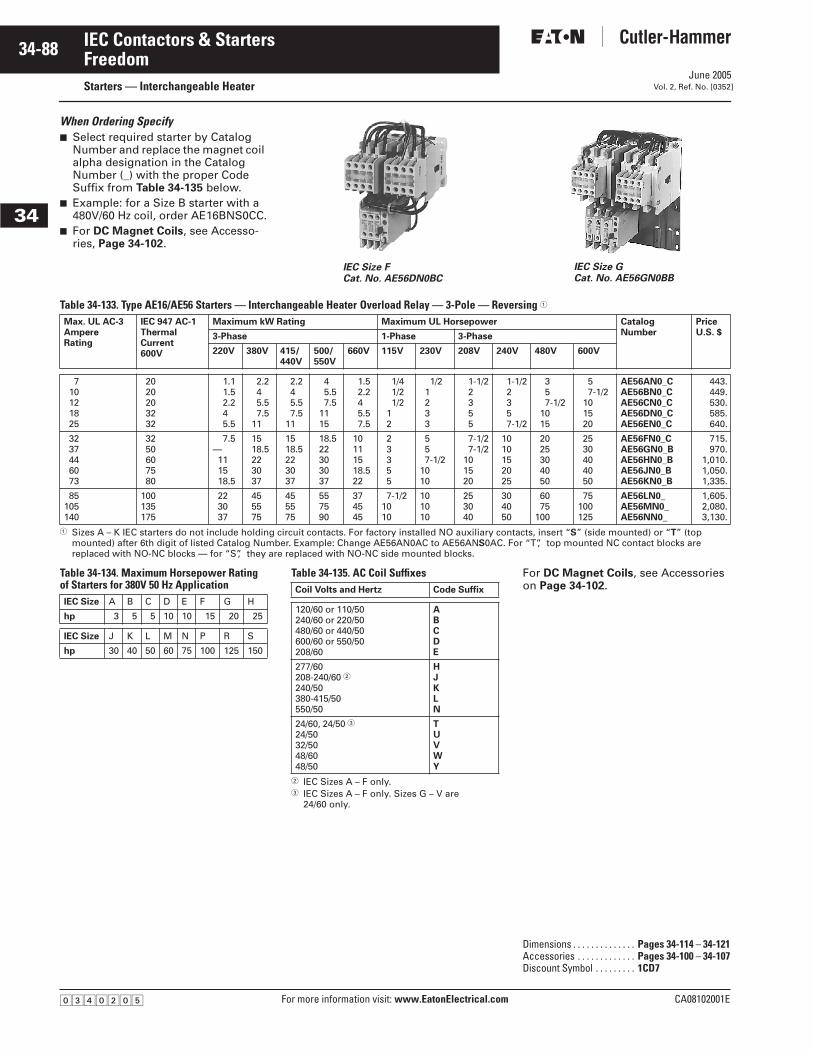
June 2005
34-88
For more information visit: www.EatonElectrical.com CA08102001E
IEC Contactors & Starters
34
FreedomStarters — Interchangeable Heater Vol. 2, Ref. No. [0352]
When Ordering Specify ■ Select required starter by Catalog
Number and replace the magnet coil alpha designation in the Catalog Number (_) with the proper Code Suffix from Table 34-135 below.
■ Example: for a Size B starter with a 480V/60 Hz coil, order AE16BNS0CC.
■ For DC Magnet Coils, see Accesso-ries, Page 34-102.
Table 34-133. Type AE16/AE56 Starters — Interchangeable Heater Overload Relay — 3-Pole — Reversing �
� Sizes A – K IEC starters do not include holding circuit contacts. For factory installed NO auxiliary contacts, insert “S” (side mounted) or “T” (top mounted) after 6th digit of listed Catalog Number. Example: Change AE56AN0AC to AE56ANS0AC. For “T”, top mounted NC contact blocks are replaced with NO-NC blocks — for “S”, they are replaced with NO-NC side mounted blocks.
Table 34-134. Maximum Horsepower Ratingof Starters for 380V 50 Hz Application
Table 34-135. AC Coil Suffixes
� IEC Sizes A – F only.� IEC Sizes A – F only. Sizes G – V are
24/60 only.
For DC Magnet Coils, see Accessories on Page 34-102.
IEC Size FCat. No. AE56DN0BC
IEC Size GCat. No. AE56GN0BB
Max. UL AC-3AmpereRating
IEC 947 AC-1ThermalCurrent600V
Maximum kW Rating Maximum UL Horsepower CatalogNumber
PriceU.S. $3-Phase 1-Phase 3-Phase
220V 380V 415/440V
500/550V
660V 115V 230V 208V 240V 480V 600V
710121825
2020203232
1.11.52.245.5
2.245.57.5
11
2.245.57.5
11
45.57.5
1115
1.52.245.57.5
1/41/21/2
12
1/21233
1-1/22355
1-1/22357-1/2
357-1/2
1015
57-1/2
101520
AE56AN0_CAE56BN0_CAE56CN0_CAE56DN0_CAE56EN0_C
443.449.530.585.640.
3237446073
3250607580
7.5—111518.5
1518.5223037
1518.5223037
18.522303037
10111518.522
23355
557-1/2
1010
7-1/27-1/2
101520
1010152025
2025304050
2530404050
AE56FN0_CAE56GN0_BAE56HN0_BAE56JN0_BAE56KN0_B
715.970.
1,010.1,050.1,335.
85105140
100135175
223037
455575
455575
557590
374545
7-1/21010
101010
253040
304050
6075
100
75100125
AE56LN0_AE56MN0_AE56NN0_
1,605.2,080.3,130.
IEC Size A B C D E F G H
hp 3 5 5 10 10 15 20 25
IEC Size J K L M N P R S
hp 30 40 50 60 75 100 125 150
Coil Volts and Hertz Code Suffix
120/60 or 110/50240/60 or 220/50480/60 or 440/50600/60 or 550/50208/60
ABCDE
277/60208-240/60 �240/50380-415/50550/50
HJKLN
24/60, 24/50 �24/5032/5048/6048/50
TUVWY
Dimensions . . . . . . . . . . . . . . Pages 34-114 – 34-121Accessories . . . . . . . . . . . . . Pages 34-100 – 34-107Discount Symbol . . . . . . . . . 1CD7
�������
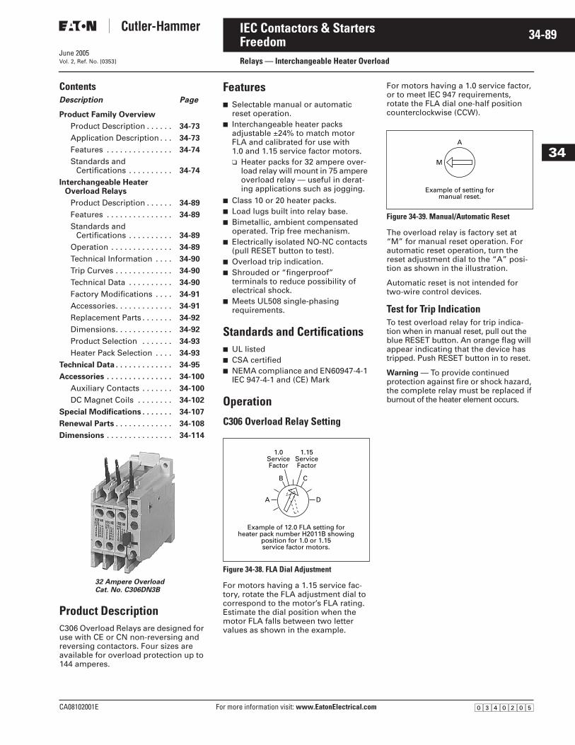
June 2005
CA08102001E For more information visit: www.EatonElectrical.com
34-89IEC Contactors & Starters
34
Freedom Relays — Interchangeable Heater OverloadVol. 2, Ref. No. [0353]
Contents Description Page
Product Family Overview
Product Description . . . . . . 34-73
Application Description . . . 34-73
Features . . . . . . . . . . . . . . . 34-74
Standards andCertifications . . . . . . . . . . 34-74
Interchangeable Heater Overload Relays
Product Description . . . . . . 34-89
Features . . . . . . . . . . . . . . . 34-89
Standards and Certifications . . . . . . . . . . 34-89
Operation . . . . . . . . . . . . . . 34-89
Technical Information . . . . 34-90
Trip Curves . . . . . . . . . . . . . 34-90
Technical Data . . . . . . . . . . 34-90
Factory Modifications . . . . 34-91
Accessories. . . . . . . . . . . . . 34-91
Replacement Parts . . . . . . . 34-92
Dimensions. . . . . . . . . . . . . 34-92
Product Selection . . . . . . . 34-93
Heater Pack Selection . . . . 34-93
Technical Data . . . . . . . . . . . . . 34-95
Accessories . . . . . . . . . . . . . . . 34-100
Auxiliary Contacts . . . . . . . 34-100
DC Magnet Coils . . . . . . . . 34-102
Special Modifications . . . . . . . 34-107
Renewal Parts . . . . . . . . . . . . . 34-108
Dimensions . . . . . . . . . . . . . . . 34-114
Product DescriptionC306 Overload Relays are designed for use with CE or CN non-reversing and reversing contactors. Four sizes are available for overload protection up to 144 amperes.
Features■ Selectable manual or automatic
reset operation.■ Interchangeable heater packs
adjustable ±24% to match motor FLA and calibrated for use with 1.0 and 1.15 service factor motors.❑ Heater packs for 32 ampere over-
load relay will mount in 75 ampere overload relay — useful in derat-ing applications such as jogging.
■ Class 10 or 20 heater packs.■ Load lugs built into relay base.■ Bimetallic, ambient compensated
operated. Trip free mechanism.■ Electrically isolated NO-NC contacts
(pull RESET button to test).■ Overload trip indication.■ Shrouded or “fingerproof”
terminals to reduce possibility of electrical shock.
■ Meets UL508 single-phasing requirements.
Standards and Certifications■ UL listed■ CSA certified■ NEMA compliance and EN60947-4-1
IEC 947-4-1 and (CE) Mark
Operation
C306 Overload Relay Setting
Figure 34-38. FLA Dial Adjustment
For motors having a 1.15 service fac-tory, rotate the FLA adjustment dial to correspond to the motor’s FLA rating. Estimate the dial position when the motor FLA falls between two letter values as shown in the example.
For motors having a 1.0 service factor, or to meet IEC 947 requirements, rotate the FLA dial one-half position counterclockwise (CCW).
Figure 34-39. Manual/Automatic Reset
The overload relay is factory set at “M” for manual reset operation. For automatic reset operation, turn the reset adjustment dial to the “A” posi-tion as shown in the illustration.
Automatic reset is not intended for two-wire control devices.
Test for Trip IndicationTo test overload relay for trip indica-tion when in manual reset, pull out the blue RESET button. An orange flag will appear indicating that the device has tripped. Push RESET button in to reset.
Warning — To provide continued protection against fire or shock hazard, the complete relay must be replaced if burnout of the heater element occurs.
32 Ampere OverloadCat. No. C306DN3B
1.0ServiceFactor
1.15ServiceFactor
A
B C
D
Example of 12.0 FLA setting forheater pack number H2011B showing
position for 1.0 or 1.15service factor motors.
A
M
Example of setting formanual reset.
�������
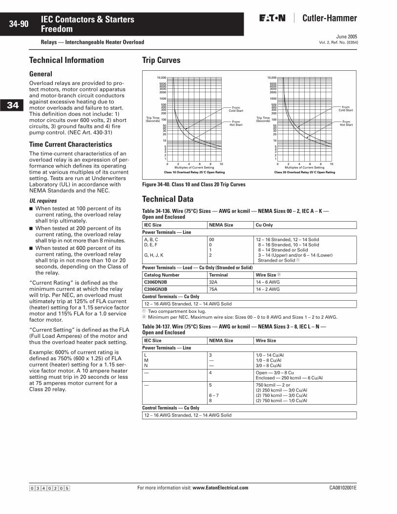
June 2005
34-90
For more information visit: www.EatonElectrical.com CA08102001E
IEC Contactors & Starters
34
FreedomRelays — Interchangeable Heater Overload Vol. 2, Ref. No. [0354]
Technical Information
GeneralOverload relays are provided to pro-tect motors, motor control apparatus and motor-branch circuit conductors against excessive heating due to motor overloads and failure to start. This definition does not include: 1) motor circuits over 600 volts, 2) short circuits, 3) ground faults and 4) fire pump control. (NEC Art. 430-31)
Time Current CharacteristicsThe time-current characteristics of an overload relay is an expression of per-formance which defines its operating time at various multiples of its current setting. Tests are run at Underwriters Laboratory (UL) in accordance with NEMA Standards and the NEC.
UL requires■ When tested at 100 percent of its
current rating, the overload relay shall trip ultimately.
■ When tested at 200 percent of its current rating, the overload relay shall trip in not more than 8 minutes.
■ When tested at 600 percent of its current rating, the overload relay shall trip in not more than 10 or 20 seconds, depending on the Class of the relay.
“Current Rating” is defined as the minimum current at which the relay will trip. Per NEC, an overload must ultimately trip at 125% of FLA current (heater) setting for a 1.15 service factor motor and 115% FLA for a 1.0 service factor motor.
“Current Setting” is defined as the FLA (Full Load Amperes) of the motor and thus the overload heater pack setting.
Example: 600% of current rating is defined as 750% (600 x 1.25) of FLA current (heater) setting for a 1.15 ser-vice factor motor. A 10 ampere heater setting must trip in 20 seconds or less at 75 amperes motor current for a Class 20 relay.
Trip Curves
Figure 34-40. Class 10 and Class 20 Trip Curves
Technical DataTable 34-136. Wire (75°C) Sizes — AWG or kcmil — NEMA Sizes 00 – 2, IEC A – K — Open and Enclosed
� Two compartment box lug.� Minimum per NEC. Maximum wire size: Sizes 00 – 0 to 8 AWG and Sizes 1 – 2 to 2 AWG.
Table 34-137. Wire (75°C) Sizes — AWG or kcmil — NEMA Sizes 3 – 8, IEC L – N — Open and Enclosed
IEC Size NEMA Size Cu Only
Power Terminals — LineA, B, CD, E, F
G, H, J, K
00012
12 – 16 Stranded, 12 – 14 Solid8 – 16 Stranded, 10 – 14 Solid8 – 14 Stranded or Solid3 – 14 (Upper) and/or 6 – 14 (Lower) Stranded or Solid �
Power Terminals — Load — Cu Only (Stranded or Solid)Catalog Number Terminal Wire Size �
C306DN3B 32A 14 – 6 AWG
C306GN3B 75A 14 – 2 AWG
Control Terminals — Cu Only12 – 16 AWG Stranded, 12 – 14 AWG Solid
IEC Size NEMA Size Wire Size
Power Terminals — LineLMN
3——
1/0 – 14 Cu/Al1/0 – 8 Cu/Al3/0 – 8 Cu/Al
— 4 Open — 3/0 – 8 CuEnclosed — 250 kcmil — 6 Cu/Al
— 5
6 – 78
750 kcmil — 2 or(2) 250 kcmil — 3/0 Cu/Al(2) 750 kcmil — 3/0 Cu/Al(2) 750 kcmil — 1/0 Cu/Al
Control Terminals — Cu Only12 – 16 AWG Stranded, 12 – 14 AWG Solid
0
12345
10
20304050
100
200300400500
1000
2000300040005000
10,000
2 4 6 8 10
FromHot Start
FromCold Start
Multiples of Current Setting
Trip Time(Seconds)
Class 10 Overload Relay 25°C Open Rating
0
12345
10
20304050
100
200300400500
1000
2000300040005000
10,000
2 4 6 8 10
FromHot Start
FromCold Start
Multiples of Current Setting
Trip Time(Seconds)
Class 20 Overload Relay 25°C Open Rating
�������
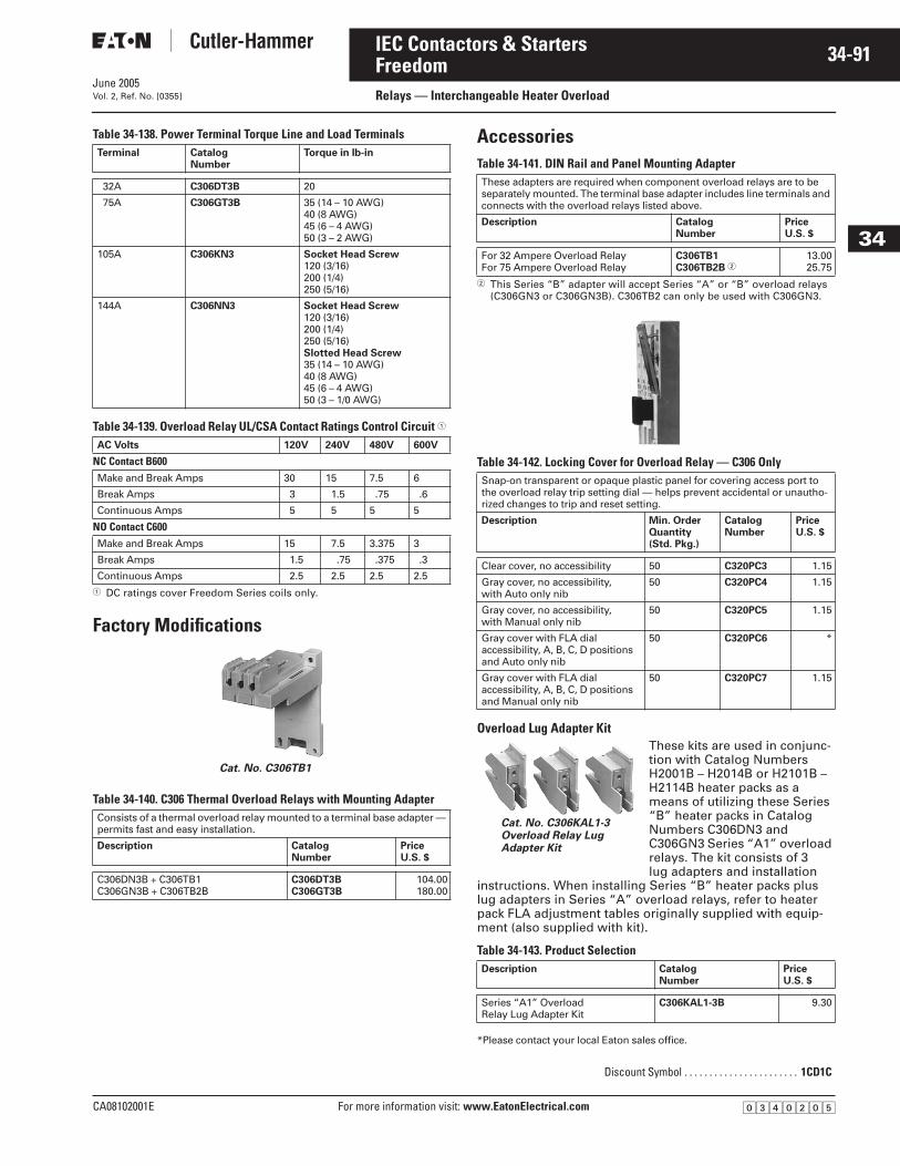
June 2005
CA08102001E For more information visit: www.EatonElectrical.com
34-91IEC Contactors & Starters
34
FreedomRelays — Interchangeable Heater OverloadVol. 2, Ref. No. [0355]
Table 34-138. Power Terminal Torque Line and Load Terminals
Table 34-139. Overload Relay UL/CSA Contact Ratings Control Circuit �
� DC ratings cover Freedom Series coils only.
Factory Modifications
Table 34-140. C306 Thermal Overload Relays with Mounting Adapter
AccessoriesTable 34-141. DIN Rail and Panel Mounting Adapter
� This Series “B” adapter will accept Series “A” or “B” overload relays (C306GN3 or C306GN3B). C306TB2 can only be used with C306GN3.
Table 34-142. Locking Cover for Overload Relay — C306 Only
Overload Lug Adapter KitThese kits are used in conjunc-tion with Catalog Numbers H2001B – H2014B or H2101B – H2114B heater packs as a means of utilizing these Series “B” heater packs in Catalog Numbers C306DN3 and C306GN3 Series “A1” overload relays. The kit consists of 3 lug adapters and installation
instructions. When installing Series “B” heater packs plus lug adapters in Series “A” overload relays, refer to heater pack FLA adjustment tables originally supplied with equip-ment (also supplied with kit).
Table 34-143. Product Selection
*Please contact your local Eaton sales office.
Terminal Catalog Number
Torque in lb-in
32A C306DT3B 20
75A C306GT3B 35 (14 – 10 AWG)40 (8 AWG)45 (6 – 4 AWG)50 (3 – 2 AWG)
105A C306KN3 Socket Head Screw120 (3/16)200 (1/4)250 (5/16)
144A C306NN3 Socket Head Screw120 (3/16)200 (1/4)250 (5/16)Slotted Head Screw35 (14 – 10 AWG)40 (8 AWG)45 (6 – 4 AWG)50 (3 – 1/0 AWG)
AC Volts 120V 240V 480V 600V
NC Contact B600Make and Break Amps 30 15 7.5 6
Break Amps 3 1.5 .75 .6
Continuous Amps 5 5 5 5
NO Contact C600Make and Break Amps 15 7.5 3.375 3
Break Amps 1.5 .75 .375 .3
Continuous Amps 2.5 2.5 2.5 2.5
Consists of a thermal overload relay mounted to a terminal base adapter — permits fast and easy installation.
Description CatalogNumber
PriceU.S. $
C306DN3B + C306TB1C306GN3B + C306TB2B
C306DT3BC306GT3B
104.00180.00
Cat. No. C306TB1
These adapters are required when component overload relays are to be separately mounted. The terminal base adapter includes line terminals and connects with the overload relays listed above.
Description CatalogNumber
PriceU.S. $
For 32 Ampere Overload RelayFor 75 Ampere Overload Relay
C306TB1C306TB2B �
13.0025.75
Snap-on transparent or opaque plastic panel for covering access port to the overload relay trip setting dial — helps prevent accidental or unautho-rized changes to trip and reset setting.
Description Min. OrderQuantity(Std. Pkg.)
CatalogNumber
PriceU.S. $
Clear cover, no accessibility 50 C320PC3 1.15
Gray cover, no accessibility, with Auto only nib
50 C320PC4 1.15
Gray cover, no accessibility, with Manual only nib
50 C320PC5 1.15
Gray cover with FLA dial accessibility, A, B, C, D positions and Auto only nib
50 C320PC6 *
Gray cover with FLA dial accessibility, A, B, C, D positions and Manual only nib
50 C320PC7 1.15
Description Catalog Number
PriceU.S. $
Series “A1” OverloadRelay Lug Adapter Kit
C306KAL1-3B 9.30
Discount Symbol . . . . . . . . . . . . . . . . . . . . . . . 1CD1C
Cat. No. C306KAL1-3Overload Relay Lug Adapter Kit
�������
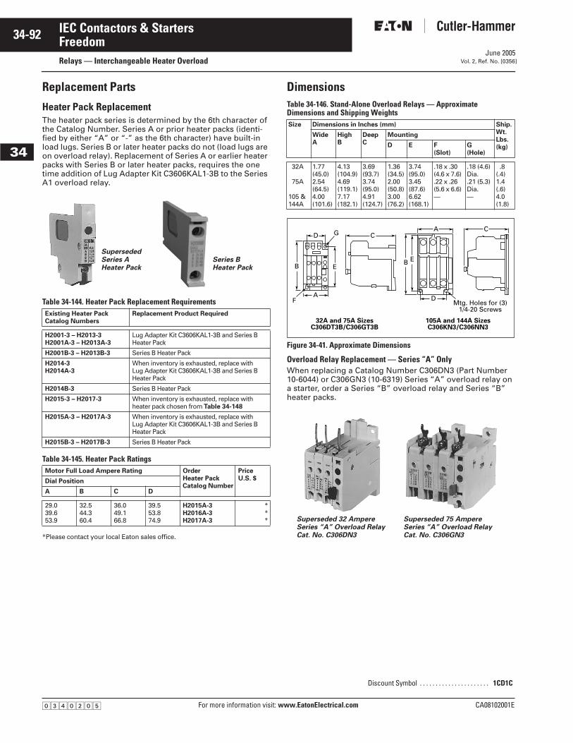
June 2005
34-92
For more information visit: www.EatonElectrical.com CA08102001E
IEC Contactors & Starters
34
FreedomRelays — Interchangeable Heater Overload Vol. 2, Ref. No. [0356]
Replacement Parts
Heater Pack Replacement The heater pack series is determined by the 6th character of the Catalog Number. Series A or prior heater packs (identi-fied by either “A” or “-” as the 6th character) have built-in load lugs. Series B or later heater packs do not (load lugs are on overload relay). Replacement of Series A or earlier heater packs with Series B or later heater packs, requires the one time addition of Lug Adapter Kit C3606KAL1-3B to the Series A1 overload relay.
Table 34-144. Heater Pack Replacement Requirements
Table 34-145. Heater Pack Ratings
*Please contact your local Eaton sales office.
DimensionsTable 34-146. Stand-Alone Overload Relays — Approximate Dimensions and Shipping Weights
Figure 34-41. Approximate Dimensions
Overload Relay Replacement — Series “A” OnlyWhen replacing a Catalog Number C306DN3 (Part Number 10-6044) or C306GN3 (10-6319) Series “A” overload relay on a starter, order a Series “B” overload relay and Series “B” heater packs.
Existing Heater PackCatalog Numbers
Replacement Product Required
H2001-3 – H2013-3H2001A-3 – H2013A-3
Lug Adapter Kit C3606KAL1-3B and Series B Heater Pack
H2001B-3 – H2013B-3 Series B Heater Pack
H2014-3H2014A-3
When inventory is exhausted, replace with Lug Adapter Kit C3606KAL1-3B and Series B Heater Pack
H2014B-3 Series B Heater Pack
H2015-3 – H2017-3 When inventory is exhausted, replace with heater pack chosen from Table 34-148
H2015A-3 – H2017A-3 When inventory is exhausted, replace with Lug Adapter Kit C3606KAL1-3B and Series B Heater Pack
H2015B-3 – H2017B-3 Series B Heater Pack
Motor Full Load Ampere Rating Order Heater PackCatalog Number
PriceU.S. $Dial Position
A B C D
29.039.653.9
32.544.360.4
36.049.166.8
39.553.874.9
H2015A-3H2016A-3H2017A-3
***
SupersededSeries AHeater Pack
Series BHeater Pack
Size Dimensions in Inches (mm) Ship.Wt.Lbs. (kg)
WideA
HighB
DeepC
Mounting
D E F (Slot)
G (Hole)
32A
75A
105 & 144A
1.77(45.0)2.54(64.5)4.00(101.6)
4.13(104.9)4.69(119.1)7.17(182.1)
3.69(93.7)3.74(95.0)4.91(124.7)
1.36(34.5)2.00(50.8)3.00(76.2)
3.74(95.0)3.45(87.6)6.62(168.1)
.18 x .30(4.6 x 7.6).22 x .26(5.6 x 6.6)—
.18 (4.6)Dia..21 (5.3)Dia.—
.8 (.4)1.4 (.6)4.0 (1.8)
Discount Symbol . . . . . . . . . . . . . . . . . . . . . . 1CD1C
DA C
C
EBEB
A DF
32A and 75A SizesC306DT3B/C306GT3B
105A and 144A SizesC306KN3/C306NN3
G
Mtg. Holes for (3)1/4-20 Screws
Superseded 32 AmpereSeries “A” Overload RelayCat. No. C306DN3
Superseded 75 AmpereSeries “A” Overload RelayCat. No. C306GN3
�������
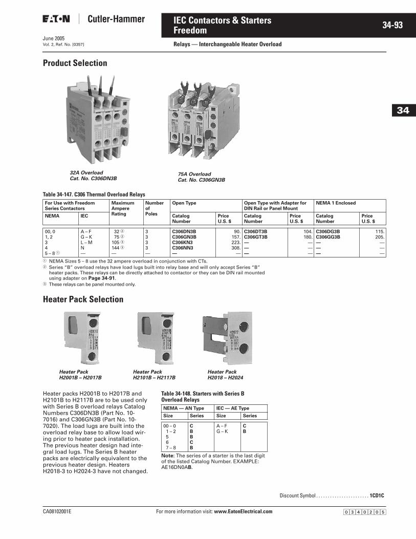
June 2005
CA08102001E For more information visit: www.EatonElectrical.com
34-93IEC Contactors & Starters
34
FreedomRelays — Interchangeable Heater OverloadVol. 2, Ref. No. [0357]
Product Selection
Table 34-147. C306 Thermal Overload Relays
� NEMA Sizes 5 – 8 use the 32 ampere overload in conjunction with CTs.� Series “B” overload relays have load lugs built into relay base and will only accept Series “B”
heater packs. These relays can be directly attached to contactor or they can be DIN rail mounted using adapter on Page 34-91.
� These relays can be panel mounted only.
Heater Pack Selection
Heater packs H2001B to H2017B and H2101B to H2117B are to be used only with Series B overload relays Catalog Numbers C306DN3B (Part No. 10-7016) and C306GN3B (Part No. 10-7020). The load lugs are built into the overload relay base to allow load wir-ing prior to heater pack installation. The previous heater design had inte-gral load lugs. The Series B heater packs are electrically equivalent to the previous heater design. Heaters H2018-3 to H2024-3 have not changed.
Table 34-148. Starters with Series B Overload Relays
Note: The series of a starter is the last digit of the listed Catalog Number. EXAMPLE: AE16DN0AB.
For Use with FreedomSeries Contactors
MaximumAmpereRating
NumberofPoles
Open Type Open Type with Adapter for DIN Rail or Panel Mount
NEMA 1 Enclosed
NEMA IEC CatalogNumber
PriceU.S. $
CatalogNumber
PriceU.S. $
CatalogNumber
PriceU.S. $
00, 01, 2345 – 8 �
A – FG – KL – MN—
32 �75 �
105 �144 �—
3333—
C306DN3BC306GN3BC306KN3C306NN3—
90.157.223.308.
—
C306DT3BC306GT3B———
104.180.
———
C306DG3BC306GG3B———
115.205.
———
32A OverloadCat. No. C306DN3B
75A OverloadCat. No. C306GN3B
Heater PackH2001B – H2017B
Heater PackH2101B – H2117B
Heater PackH2018 – H2024
NEMA — AN Type IEC — AE Type
Size Series Size Series
00 – 01 – 2567 – 8
CBBCB
A – FG – K
CB
Discount Symbol . . . . . . . . . . . . . . . . . . . . . . . 1CD1C
�������
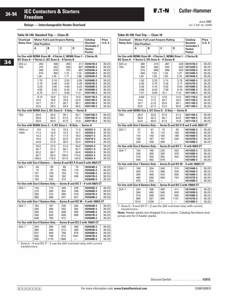
June 2005
34-94
For more information visit: www.EatonElectrical.com CA08102001E
IEC Contactors & Starters
34
Freedom Relays — Interchangeable Heater Overload Vol. 2, Ref. No. [0358]
Table 34-149. Standard Trip — Class 20
� Sizes 5 – 8 and IEC P – Z use the 32A overload relay with current transformers.
Table 34-150. Fast Trip — Class 10
� Sizes 5 – 8 and IEC P – Z use the 32A overload relay with current transformers.
Note: Heater packs are shipped 3 to a carton. Catalog Numbers and prices are for 3 heater packs.
OverloadRelay Size
Motor Full Load Ampere Rating CatalogNumber(Includes 3HeaterPacks)
PriceU.S. $Dial Position
A B C D
For Use with NEMA Sizes 00 – 0 Series C, NEMA Sizes 1 – 2 Series B;IEC Sizes A – F Series C, IEC Sizes G – K Series B32A or75A
.254
.375
.560
.8141.20
.306
.452
.676
.9831.45
.359
.530
.7911.151.71
.411
.607
.9071.321.96
H2001B-3H2002B-3H2003B-3H2004B-3H2005B-3
39.2539.2539.2539.2539.25
1.792.153.234.556.75
2.162.603.905.508.17
2.533.044.566.459.58
2.903.495.237.40
11.0
H2006B-3H2007B-3H2008B-3H2009B-3H2010B-3
39.2539.2539.2539.2539.25
9.1414.018.723.5
10.816.922.728.5
12.419.926.733.5
14.022.830.738.5
H2011B-3H2012B-3H2013B-3H2014B-3
39.2539.2539.2539.25
For Use with NEMA Size 2, IEC Sizes G – K Only — Series B75A 29.0
39.653.9
34.045.560.9
39.151.567.9
44.157.474.9
H2015B-3H2016B-3H2017B-3
39.2539.2539.25
For Use with NEMA Sizes 3 – 4, IEC Sizes L – N Only — Series A105A or144A
8.011.414.318.024.6
9.212.815.720.227.6
10.314.317.422.330.5
11.515.719.024.533.4
H2025-3H2026-3H2027-3H2018-3H2019-3
39.2539.2539.2539.2539.25
33.545.762.284.7
106.0
37.551.269.795.0
118.0
41.556.777.1
105.0131.0
45.662.184.6
115.0144.0
H2020-3H2021-3H2022-3H2023-3H2024-3
39.2539.2539.2539.2539.25
For Use with Size 5 Starters — Series B and IEC P, R and S with 300/5 CT32A � 49
72107129194
5987
130156234
69103152182274
79118174209—
H2004B-3H2005B-3H2006B-3H2007B-3H2008B-3
39.2539.2539.2539.2539.25
For Use with Size 6 Starters Only — Series B and IEC T – V with 600/5 CT32A � 144
215258388
174259312468
205304365547
235348419627
H2005B-3H2006B-3H2007B-3H2008B-3
39.2539.2539.2539.25
For Use with Size 7 Starters Only — Series B and IEC W – X with 1000/5 CT32A � 163
240358430646
197290432520780
230342506608912
264392580698—
H2004B-3H2005B-3H2006B-3H2007B-3H2008B-3
39.2539.2539.2539.2539.25
For Use with Size 8 Starters Only — Series B and IEC Z with 1500/5 CT32A � 244
360537645969
295435648780
1170
345513759912
1368
396588870
1047—
H2004B-3H2005B-3H2006B-3H2007B-3H2008B-3
39.2539.2539.2539.2539.25
OverloadRelay Size
Motor Full Load Ampere Rating CatalogNumber(Includes 3HeaterPacks)
PriceU.S. $Dial Position
A B C D
For Use with NEMA Sizes 00 – 0 Series C, NEMA Sizes 1 – 2 Series B;IEC Sizes A – F Series C, IEC Sizes G – K Series B32A or75A
.260
.384
.570
.8461.28
.313
.464
.6881.021.55
.367
.543
.8061.201.83
.420
.623
.9241.372.10
H2101B-3H2102B-3H2103B-3H2104B-3H2105B-3
39.2539.2539.2539.2539.25
1.922.303.384.967.07
2.332.794.106.038.58
2.743.284.827.09
10.1
3.153.775.548.16
11.6
H2106B-3H2107B-3H2108B-3H2109B-3H2110B-3
39.2539.2539.2539.2539.25
9.6014.418.723.5
11.217.521.827.3
12.820.725.031.0
14.423.828.134.8
H2111B-3H2112B-3H2113B-3H2114B-3
39.2539.2539.2539.25
For Use with NEMA Size 2, IEC Sizes G – K Only — Series B75A 28.3
36.653.8
32.642.360.8
37.048.167.9
41.353.874.9
H2115B-3H2116B-3H2117B-3
39.2539.2539.25
For Use with Size 5 Starters Only — Series B and IEC P, R and S with 300/5 CT32A � 51
77115138203
6193
140167246
72110164197289
82126189226—
H2104B-3H2105B-3H2106B-3H2107B-3H2108B-3
39.2539.2539.2539.2539.25
For Use with Size 6 Starters Only — Series B and IEC T – V with 600/5 CT32A � 154
230276406
186280335492
220329394578
252378452—
H2105B-3H2106B-3H2107B-3H2108B-3
39.2539.2539.2539.25
For Use with Size 7 Starters Only — Series B and IEC W – X with 1000/5 CT32A � 169
256384460676
204310466558820
240366543656—
274420630754—
H2104B-3H2105B-3H2106B-3H2107B-3H2108B-3
39.2539.2539.2539.2539.25
For Use with Size 8 Starters Only — Series B and IEC Z with 1500/5 CT32A � 254
384576690
1014
306465699837
1230
360549822984—
411630945
1131—
H2104B-3H2105B-3H2106B-3H2107B-3H2108B-3
39.2539.2539.2539.2539.25
Discount Symbol . . . . . . . . . . . . . . . . . . . . . . . 1CD1C
�������
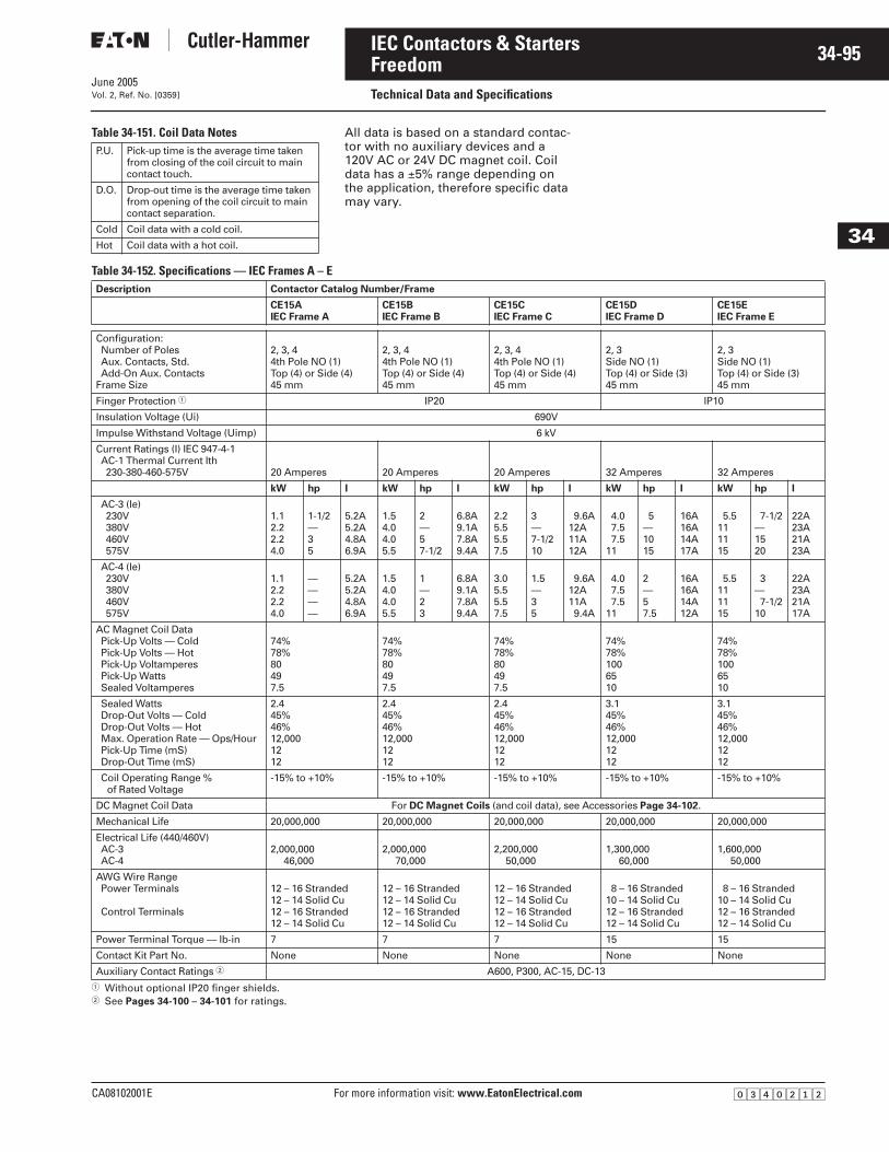
June 2005
CA08102001E For more information visit: www.EatonElectrical.com
34-95IEC Contactors & Starters
34
FreedomTechnical Data and SpecificationsVol. 2, Ref. No. [0359]
Table 34-151. Coil Data Notes All data is based on a standard contac-tor with no auxiliary devices and a 120V AC or 24V DC magnet coil. Coil data has a ±5% range depending on the application, therefore specific data may vary.
Table 34-152. Specifications — IEC Frames A – E
� Without optional IP20 finger shields.� See Pages 34-100 – 34-101 for ratings.
P.U. Pick-up time is the average time taken from closing of the coil circuit to main contact touch.
D.O. Drop-out time is the average time taken from opening of the coil circuit to main contact separation.
Cold Coil data with a cold coil.
Hot Coil data with a hot coil.
Description Contactor Catalog Number/Frame
CE15AIEC Frame A
CE15BIEC Frame B
CE15CIEC Frame C
CE15DIEC Frame D
CE15EIEC Frame E
Configuration:Number of PolesAux. Contacts, Std.Add-On Aux. Contacts
Frame Size
2, 3, 44th Pole NO (1)Top (4) or Side (4)45 mm
2, 3, 44th Pole NO (1)Top (4) or Side (4)45 mm
2, 3, 44th Pole NO (1)Top (4) or Side (4)45 mm
2, 3Side NO (1)Top (4) or Side (3)45 mm
2, 3Side NO (1)Top (4) or Side (3)45 mm
Finger Protection � IP20 IP10
Insulation Voltage (Ui) 690V
Impulse Withstand Voltage (Uimp) 6 kV
Current Ratings (I) IEC 947-4-1AC-1 Thermal Current Ith230-380-460-575V 20 Amperes 20 Amperes 20 Amperes 32 Amperes 32 Amperes
kW hp I kW hp I kW hp I kW hp I kW hp I
AC-3 (le)230V380V460V575V
1.12.22.24.0
1-1/2—35
5.2A5.2A4.8A6.9A
1.54.04.05.5
2—57-1/2
6.8A9.1A7.8A9.4A
2.25.55.57.5
3—7-1/210
9.6A12A11A12A
4.07.57.5
11
5—1015
16A16A14A17A
5.5111115
7-1/2—1520
22A23A21A23A
AC-4 (le)230V380V460V575V
1.12.22.24.0
————
5.2A5.2A4.8A6.9A
1.54.04.05.5
1—23
6.8A9.1A7.8A9.4A
3.05.55.57.5
1.5—35
9.6A12A11A9.4A
4.07.57.5
11
2—57.5
16A16A14A12A
5.5111115
3—7-1/2
10
22A23A21A17A
AC Magnet Coil DataPick-Up Volts — ColdPick-Up Volts — HotPick-Up VoltamperesPick-Up WattsSealed Voltamperes
74%78%80497.5
74%78%80497.5
74%78%80497.5
74%78%1006510
74%78%1006510
Sealed WattsDrop-Out Volts — ColdDrop-Out Volts — HotMax. Operation Rate — Ops/HourPick-Up Time (mS)Drop-Out Time (mS)
2.445%46%12,0001212
2.445%46%12,0001212
2.445%46%12,0001212
3.145%46%12,0001212
3.145%46%12,0001212
Coil Operating Range % of Rated Voltage
-15% to +10% -15% to +10% -15% to +10% -15% to +10% -15% to +10%
DC Magnet Coil Data For DC Magnet Coils (and coil data), see Accessories Page 34-102.
Mechanical Life 20,000,000 20,000,000 20,000,000 20,000,000 20,000,000
Electrical Life (440/460V)AC-3AC-4
2,000,00046,000
2,000,00070,000
2,200,00050,000
1,300,00060,000
1,600,00050,000
AWG Wire RangePower Terminals
Control Terminals
12 – 16 Stranded12 – 14 Solid Cu12 – 16 Stranded12 – 14 Solid Cu
12 – 16 Stranded12 – 14 Solid Cu12 – 16 Stranded12 – 14 Solid Cu
12 – 16 Stranded12 – 14 Solid Cu12 – 16 Stranded12 – 14 Solid Cu
8 – 16 Stranded10 – 14 Solid Cu12 – 16 Stranded12 – 14 Solid Cu
8 – 16 Stranded10 – 14 Solid Cu12 – 16 Stranded12 – 14 Solid Cu
Power Terminal Torque — lb-in 7 7 7 15 15
Contact Kit Part No. None None None None None
Auxiliary Contact Ratings � A600, P300, AC-15, DC-13
�������
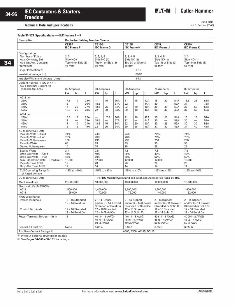
June 2005
34-96
For more information visit: www.EatonElectrical.com CA08102001E
IEC Contactors & Starters
34
FreedomTechnical Data and Specifications Vol. 2, Ref. No. [0360]
Table 34-153. Specifications — IEC Frames F – K
� Without optional IP20 finger shields.� See Pages 34-100 – 34-101 for ratings.
Description Contactor Catalog Number/Frame
CE15FIEC Frame F
CE15GIEC Frame G
CE15HIEC Frame H
CE15JIEC Frame J
CE15KIEC Frame K
Configuration:Number of PolesAux. Contacts, Std.Add-On Aux. Contacts
Frame Size
2, 3Side NO (1)Top (4) or Side (3)45 mm
2, 3, 4, 5Side NO (1)Top (4) or Side (3)65 mm
2, 3, 4, 5Side NO (1)Top (4) or Side (3)65 mm
2, 3, 4, 5Side NO (1)Top (4) or Side (3)65 mm
2, 3Side NO (1)Top (4) or Side (3)65 mm
Finger Protection � IP10
Insulation Voltage (Ui) 690V
Impulse Withstand Voltage (Uimp) 6 kV
Current Ratings (I) IEC 947-4-1AC-1 Thermal Current Ith230-380-460-575V 32 Amperes 50 Amperes 60 Amperes 75 Amperes 80 Amperes
kW hp I kW hp I kW hp I kW hp I kW hp I
AC-3 (le)230V380V460V575V
7.5151518.5
10—2025
28A30A27A28A
—18.518.522
10—2530
36A37A34A34A
11222230
15—3040
42A44A40A45A
15303030
20—4040
54A59A52A45A
18.5373737
25—5050
68A73A65A55A
AC-4 (le)230V380V460V575V
5.5111115
5—1015
22A23A21A19A
—18.518.522
7.5—1520
36A37A34A34A
11222230
10—2025
42A44A40A45A
15303037
10—2530
54A59A52A45A
15303037
15—3040
54A59A52A45A
AC Magnet Coil DataPick-Up Volts — ColdPick-Up Volts — HotPick-Up VoltamperesPick-Up WattsSealed Voltamperes
74%78%1006510
74%78%2309528
74%78%2309528
74%78%2309528
74%78%2309528
Sealed WattsDrop-Out Volts — ColdDrop-Out Volts — HotMax. Operation Rate — Ops/HourPick-Up Time (mS)Drop-Out Time (mS)
3.145%46%12,0001212
7.849%50%12,0002014
7.849%50%12,0002014
7.849%50%12,0002014
7.849%50%12,0002014
Coil Operating Range % of Rated Voltage
-15% to +10% -15% to +10% -15% to +10% -15% to +10% -15% to +10%
DC Magnet Coil Data For DC Magnet Coils (and coil data), see Accessories Page 34-102.
Mechanical Life 20,000,000 10,000,000 10,000,000 10,000,000 10,000,000
Electrical Life (440/460V)AC-3AC-4
1,500,00055,000
1,400,00070,000
1,500,00075,000
1,600,00040,000
1,600,00032,000
AWG Wire RangePower Terminals
Control Terminals
8 – 16 Stranded10 – 14 Solid Cu
12 – 16 Stranded12 – 14 Solid Cu
2 – 14 (Upper) and/or 6 – 14 (Lower)Stranded or Solid Cu12 – 16 Stranded12 – 14 Solid Cu
2 – 14 (Upper) and/or 6 – 14 (Lower)Stranded or Solid Cu12 – 16 Stranded12 – 14 Solid Cu
2 – 14 (Upper) and/or 6 – 14 (Lower)Stranded or Solid Cu12 – 16 Stranded12 – 14 Solid Cu
2 – 14 (Upper) and/or 6 – 14 (Lower)Stranded or Solid Cu12 – 16 Stranded12 – 14 Solid Cu
Power Terminal Torque — lb-in 15 40 (14 – 8 AWG)45 (6 – 4 AWG)50 (3 AWG)
40 (14 – 8 AWG)45 (6 – 4 AWG)50 (3 AWG)
40 (14 – 8 AWG)45 (6 – 4 AWG)50 (3 AWG)
40 (14 – 8 AWG)45 (6 – 4 AWG)50 (3 AWG)
Contact Kit Part No. None 6-65-4 6-65-6 6-65-8 6-65-17
Auxiliary Contact Ratings � A600, P300, AC-15, DC-13
�������
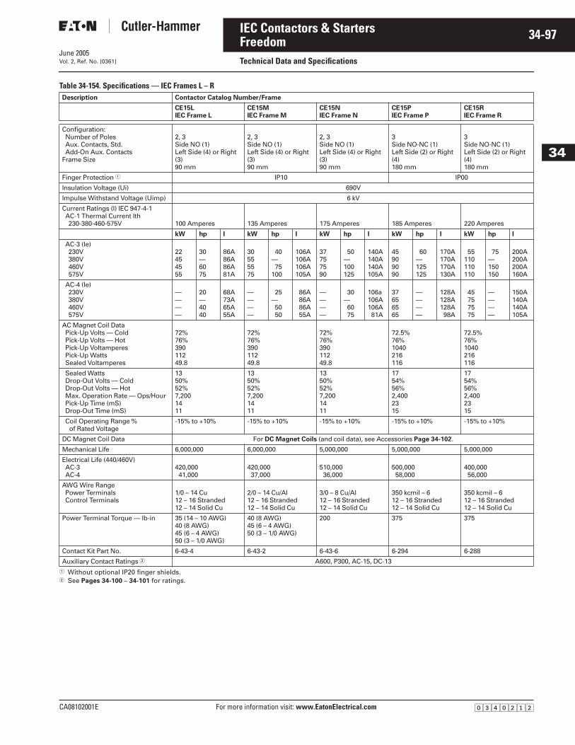
June 2005
CA08102001E For more information visit: www.EatonElectrical.com
34-97IEC Contactors & Starters
34
FreedomTechnical Data and SpecificationsVol. 2, Ref. No. [0361]
Table 34-154. Specifications — IEC Frames L – R
� Without optional IP20 finger shields.� See Pages 34-100 – 34-101 for ratings.
Description Contactor Catalog Number/Frame
CE15LIEC Frame L
CE15MIEC Frame M
CE15NIEC Frame N
CE15PIEC Frame P
CE15RIEC Frame R
Configuration:Number of PolesAux. Contacts, Std.Add-On Aux. Contacts
Frame Size
2, 3Side NO (1)Left Side (4) or Right (3)90 mm
2, 3Side NO (1)Left Side (4) or Right (3)90 mm
2, 3Side NO (1)Left Side (4) or Right (3)90 mm
3Side NO-NC (1)Left Side (2) or Right (4)180 mm
3Side NO-NC (1)Left Side (2) or Right (4)180 mm
Finger Protection � IP10 IP00
Insulation Voltage (Ui) 690V
Impulse Withstand Voltage (Uimp) 6 kV
Current Ratings (I) IEC 947-4-1AC-1 Thermal Current Ith230-380-460-575V 100 Amperes 135 Amperes 175 Amperes 185 Amperes 220 Amperes
kW hp I kW hp I kW hp I kW hp I kW hp I
AC-3 (le)230V380V460V575V
22454555
30—6075
86A86A86A81A
30555575
40—75
100
106A106A106A105A
37757590
50—100125
140A140A140A105A
45909090
60—125125
170A170A170A130A
55110110110
75—150150
200A200A200A160A
AC-4 (le)230V380V460V575V
————
20—4040
68A73A65A55A
————
25—5050
86A86A86A55A
————
30—6075
106a106A106A81A
37656565
————
128A128A128A98A
45757575
————
150A140A140A105A
AC Magnet Coil DataPick-Up Volts — ColdPick-Up Volts — HotPick-Up VoltamperesPick-Up WattsSealed Voltamperes
72%76%39011249.8
72%76%39011249.8
72%76%39011249.8
72.5%76%1040216116
72.5%76%1040216116
Sealed WattsDrop-Out Volts — ColdDrop-Out Volts — HotMax. Operation Rate — Ops/HourPick-Up Time (mS)Drop-Out Time (mS)
1350%52%7,2001411
1350%52%7,2001411
1350%52%7,2001411
1754%56%2,4002315
1754%56%2,4002315
Coil Operating Range % of Rated Voltage
-15% to +10% -15% to +10% -15% to +10% -15% to +10% -15% to +10%
DC Magnet Coil Data For DC Magnet Coils (and coil data), see Accessories Page 34-102.
Mechanical Life 6,000,000 6,000,000 5,000,000 5,000,000 5,000,000
Electrical Life (440/460V)AC-3AC-4
420,00041,000
420,00037,000
510,00036,000
500,00058,000
400,00056,000
AWG Wire RangePower TerminalsControl Terminals
1/0 – 14 Cu12 – 16 Stranded12 – 14 Solid Cu
2/0 – 14 Cu/Al12 – 16 Stranded12 – 14 Solid Cu
3/0 – 8 Cu/Al12 – 16 Stranded12 – 14 Solid Cu
350 kcmil – 612 – 16 Stranded12 – 14 Solid Cu
350 kcmil – 612 – 16 Stranded12 – 14 Solid Cu
Power Terminal Torque — lb-in 35 (14 – 10 AWG)40 (8 AWG)45 (6 – 4 AWG)50 (3 – 1/0 AWG)
40 (8 AWG)45 (6 – 4 AWG)50 (3 – 1/0 AWG)
200 375 375
Contact Kit Part No. 6-43-4 6-43-2 6-43-6 6-294 6-288
Auxiliary Contact Ratings � A600, P300, AC-15, DC-13
�������
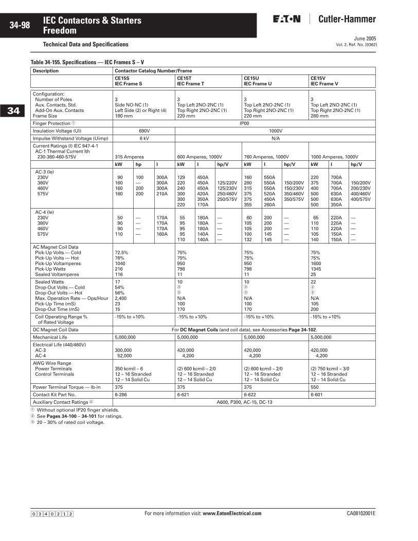
June 2005
34-98
For more information visit: www.EatonElectrical.com CA08102001E
IEC Contactors & Starters
34
FreedomTechnical Data and Specifications Vol. 2, Ref. No. [0362]
Table 34-155. Specifications — IEC Frames S – V
� Without optional IP20 finger shields.� See Pages 34-100 – 34-101 for ratings. � 20 – 30% of rated coil voltage.
Description Contactor Catalog Number/Frame
CE15SIEC Frame S
CE15TIEC Frame T
CE15UIEC Frame U
CE15VIEC Frame V
Configuration:Number of PolesAux. Contacts, Std.Add-On Aux. Contacts
Frame Size
3Side NO-NC (1)Left Side (2) or Right (4)180 mm
3Top Left 2NO-2NC (1)Top Right 2NO-2NC (1)220 mm
3Top Left 2NO-2NC (1)Top Right 2NO-2NC (1)220 mm
3Top Left 2NO-2NC (1)Top Right 2NO-2NC (1)280 mm
Finger Protection � IP00
Insulation Voltage (Ui) 690V 1000V
Impulse Withstand Voltage (Uimp) 6 kV N/A
Current Ratings (I) IEC 947-4-1AC-1 Thermal Current Ith230-380-460-575V 315 Amperes 600 Amperes, 1000V 760 Amperes, 1000V 1000 Amperes, 1000V
kW hp I kW I hp/V kW I hp/V kW I hp/V
AC-3 (le)230V380V460V575V
90160160160
100—200200
300A300A300A210A
129220240300300220
450A450A450A420A350A170A
125/220V125/230V250/460V250/575V
160280315375375355
550A550A550A520A450A260A
150/200V150/230V350/460V350/575V
220375400500500500
700A700A700A630A630A350A
150/200V200/230V400/460V400/575V
AC-4 (le)230V380V460V575V
509090
110
————
170A170A170A160A
55959595
110
180A180A180A140A140A
—————
60105105100132
200200200145145
—————
65110110105140
220A220A220A150A150A
—————
AC Magnet Coil DataPick-Up Volts — ColdPick-Up Volts — HotPick-Up VoltamperesPick-Up WattsSealed Voltamperes
72.5%76%1040216116
75%75%95079811
75%75%95079811
75%75%1600134525
Sealed WattsDrop-Out Volts — ColdDrop-Out Volts — HotMax. Operation Rate — Ops/HourPick-Up Time (mS)Drop-Out Time (mS)
1754%56%2,4002315
10�
�
N/A100170
10�
�
N/A100170
22�
�
N/A105200
Coil Operating Range % of Rated Voltage
-15% to +10% -15% to +10% -15% to +10% -15% to +10%
DC Magnet Coil Data For DC Magnet Coils (and coil data), see Accessories Page 34-102.
Mechanical Life 5,000,000 5,000,000 5,000,000 5,000,000
Electrical Life (440/460V)AC-3AC-4
300,00052,000
420,0004,200
420,0004,200
420,0004,200
AWG Wire RangePower TerminalsControl Terminals
350 kcmil – 612 – 16 Stranded12 – 14 Solid Cu
(2) 600 kcmil – 2/012 – 16 Stranded12 – 14 Solid Cu
(2) 600 kcmil – 2/012 – 16 Stranded12 – 14 Solid Cu
(2) 750 kcmil – 3/012 – 16 Stranded12 – 14 Solid Cu
Power Terminal Torque — lb-in 375 375 375 550
Contact Kit Part No. 6-286 6-621 6-622 6-601
Auxiliary Contact Ratings � A600, P300, AC-15, DC-13
�������
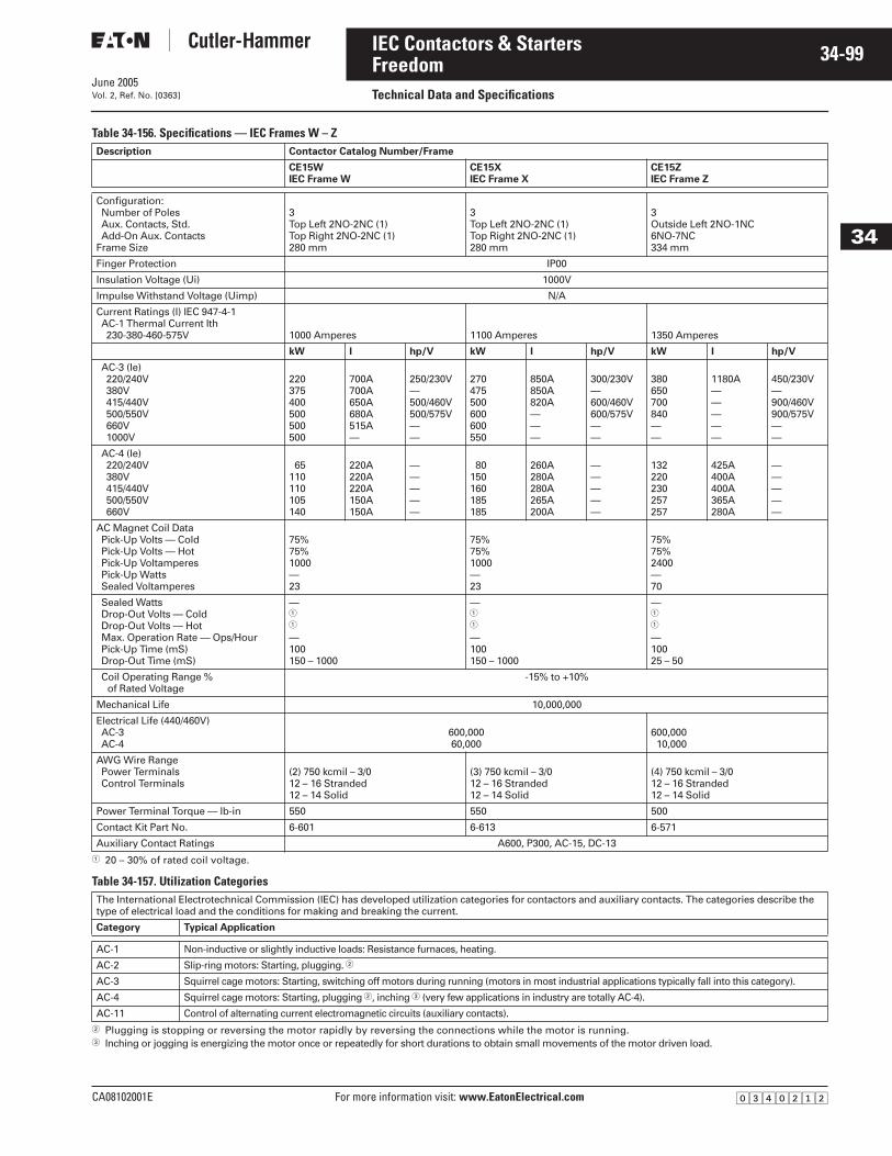
June 2005
CA08102001E For more information visit: www.EatonElectrical.com
34-99IEC Contactors & Starters
34
FreedomTechnical Data and SpecificationsVol. 2, Ref. No. [0363]
Table 34-156. Specifications — IEC Frames W – Z
� 20 – 30% of rated coil voltage.
Table 34-157. Utilization Categories
� Plugging is stopping or reversing the motor rapidly by reversing the connections while the motor is running.� Inching or jogging is energizing the motor once or repeatedly for short durations to obtain small movements of the motor driven load.
Description Contactor Catalog Number/Frame
CE15WIEC Frame W
CE15XIEC Frame X
CE15ZIEC Frame Z
Configuration:Number of PolesAux. Contacts, Std.Add-On Aux. Contacts
Frame Size
3Top Left 2NO-2NC (1)Top Right 2NO-2NC (1)280 mm
3Top Left 2NO-2NC (1)Top Right 2NO-2NC (1)280 mm
3Outside Left 2NO-1NC6NO-7NC334 mm
Finger Protection IP00
Insulation Voltage (Ui) 1000V
Impulse Withstand Voltage (Uimp) N/A
Current Ratings (I) IEC 947-4-1AC-1 Thermal Current Ith230-380-460-575V 1000 Amperes 1100 Amperes 1350 Amperes
kW I hp/V kW I hp/V kW I hp/V
AC-3 (le)220/240V380V415/440V500/550V660V1000V
220375400500500500
700A700A650A680A515A—
250/230V—500/460V500/575V——
270475500600600550
850A850A820A———
300/230V—600/460V600/575V——
380650700840——
1180A—————
450/230V—900/460V900/575V——
AC-4 (le)220/240V380V415/440V500/550V660V
65110110105140
220A220A220A150A150A
—————
80150160185185
260A280A280A265A200A
—————
132220230257257
425A400A400A365A280A
—————
AC Magnet Coil DataPick-Up Volts — ColdPick-Up Volts — HotPick-Up VoltamperesPick-Up WattsSealed Voltamperes
75%75%1000—23
75%75%1000—23
75%75%2400—70
Sealed WattsDrop-Out Volts — ColdDrop-Out Volts — HotMax. Operation Rate — Ops/HourPick-Up Time (mS)Drop-Out Time (mS)
—�
�
—100150 – 1000
—�
�
—100150 – 1000
—�
�
—10025 – 50
Coil Operating Range % of Rated Voltage
-15% to +10%
Mechanical Life 10,000,000
Electrical Life (440/460V)AC-3AC-4
600,00060,000
600,00010,000
AWG Wire RangePower TerminalsControl Terminals
(2) 750 kcmil – 3/012 – 16 Stranded12 – 14 Solid
(3) 750 kcmil – 3/012 – 16 Stranded12 – 14 Solid
(4) 750 kcmil – 3/012 – 16 Stranded12 – 14 Solid
Power Terminal Torque — lb-in 550 550 500
Contact Kit Part No. 6-601 6-613 6-571
Auxiliary Contact Ratings A600, P300, AC-15, DC-13
The International Electrotechnical Commission (IEC) has developed utilization categories for contactors and auxiliary contacts. The categories describe the type of electrical load and the conditions for making and breaking the current.
Category Typical Application
AC-1 Non-inductive or slightly inductive loads: Resistance furnaces, heating.
AC-2 Slip-ring motors: Starting, plugging. �
AC-3 Squirrel cage motors: Starting, switching off motors during running (motors in most industrial applications typically fall into this category).
AC-4 Squirrel cage motors: Starting, plugging �, inching � (very few applications in industry are totally AC-4).
AC-11 Control of alternating current electromagnetic circuits (auxiliary contacts).
�������
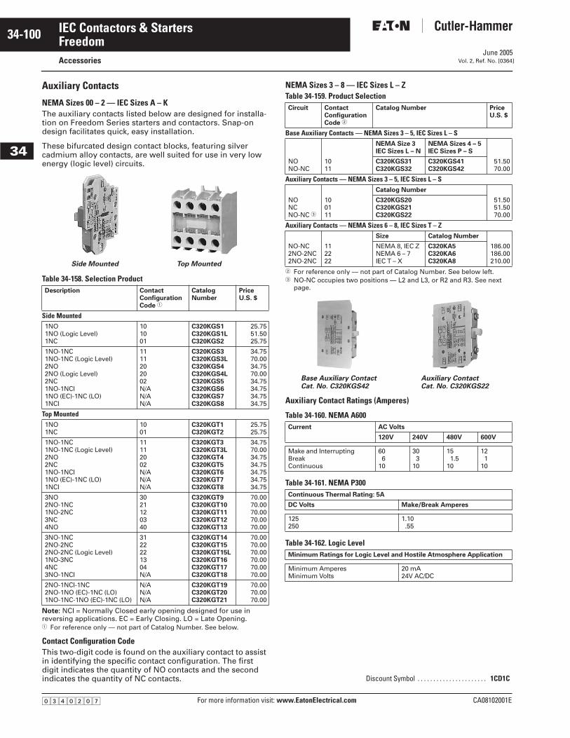
June 2005
34-100
For more information visit: www.EatonElectrical.com CA08102001E
IEC Contactors & Starters
34
FreedomAccessories Vol. 2, Ref. No. [0364]
Auxiliary Contacts
NEMA Sizes 00 – 2 — IEC Sizes A – KThe auxiliary contacts listed below are designed for installa-tion on Freedom Series starters and contactors. Snap-on design facilitates quick, easy installation.
These bifurcated design contact blocks, featuring silver cadmium alloy contacts, are well suited for use in very low energy (logic level) circuits.
Table 34-158. Selection Product
Note: NCI = Normally Closed early opening designed for use in reversing applications. EC = Early Closing. LO = Late Opening.� For reference only — not part of Catalog Number. See below.
Contact Configuration CodeThis two-digit code is found on the auxiliary contact to assist in identifying the specific contact configuration. The first digit indicates the quantity of NO contacts and the second indicates the quantity of NC contacts.
NEMA Sizes 3 – 8 — IEC Sizes L – ZTable 34-159. Product Selection
� For reference only — not part of Catalog Number. See below left.� NO-NC occupies two positions — L2 and L3, or R2 and R3. See next
page.
Auxiliary Contact Ratings (Amperes)
Table 34-160. NEMA A600
Table 34-161. NEMA P300
Table 34-162. Logic Level
Description ContactConfiguration Code �
CatalogNumber
PriceU.S. $
Side Mounted1NO1NO (Logic Level)1NC
101001
C320KGS1C320KGS1LC320KGS2
25.7551.5025.75
1NO-1NC1NO-1NC (Logic Level)2NO2NO (Logic Level)2NC1NO-1NCI1NO (EC)-1NC (LO)1NCI
1111202002N/AN/AN/A
C320KGS3C320KGS3LC320KGS4C320KGS4LC320KGS5C320KGS6C320KGS7C320KGS8
34.7570.0034.7570.0034.7534.7534.7534.75
Top Mounted1NO1NC
1001
C320KGT1C320KGT2
25.7525.75
1NO-1NC1NO-1NC (Logic Level)2NO2NC1NO-1NCI1NO (EC)-1NC (LO)1NCI
11112002N/AN/AN/A
C320KGT3C320KGT3LC320KGT4C320KGT5C320KGT6C320KGT7C320KGT8
34.7570.0034.7534.7534.7534.7534.75
3NO2NO-1NC1NO-2NC3NC4NO
3021120340
C320KGT9C320KGT10C320KGT11C320KGT12C320KGT13
70.0070.0070.0070.0070.00
3NO-1NC2NO-2NC2NO-2NC (Logic Level)1NO-3NC4NC3NO-1NCI
3122221304N/A
C320KGT14C320KGT15C320KGT15LC320KGT16C320KGT17C320KGT18
70.0070.0070.0070.0070.0070.00
2NO-1NCI-1NC2NO-1NO (EC)-1NC (LO)1NO-1NC-1NO (EC)-1NC (LO)
N/AN/AN/A
C320KGT19C320KGT20C320KGT21
70.0070.0070.00
Side Mounted Top Mounted
Circuit ContactConfigurationCode �
Catalog Number PriceU.S. $
Base Auxiliary Contacts — NEMA Sizes 3 – 5, IEC Sizes L – SNEMA Size 3IEC Sizes L – N
NEMA Sizes 4 – 5IEC Sizes P – S
NONO-NC
1011
C320KGS31C320KGS32
C320KGS41C320KGS42
51.5070.00
Auxiliary Contacts — NEMA Sizes 3 – 5, IEC Sizes L – SCatalog Number
NONCNO-NC �
100111
C320KGS20C320KGS21C320KGS22
51.5051.5070.00
Auxiliary Contacts — NEMA Sizes 6 – 8, IEC Sizes T – ZSize Catalog Number
NO-NC2NO-2NC2NO-2NC
112222
NEMA 8, IEC ZNEMA 6 – 7IEC T – X
C320KA5C320KA6C320KA8
186.00186.00210.00
Current AC Volts
120V 240V 480V 600V
Make and InterruptingBreakContinuous
606
10
303
10
151.5
10
121
10
Continuous Thermal Rating: 5A
DC Volts Make/Break Amperes
125250
1.10.55
Minimum Ratings for Logic Level and Hostile Atmosphere Application
Minimum AmperesMinimum Volts
20 mA24V AC/DC
Discount Symbol . . . . . . . . . . . . . . . . . . . . . . 1CD1C
Base Auxiliary Contact Cat. No. C320KGS42
Auxiliary ContactCat. No. C320KGS22
�������
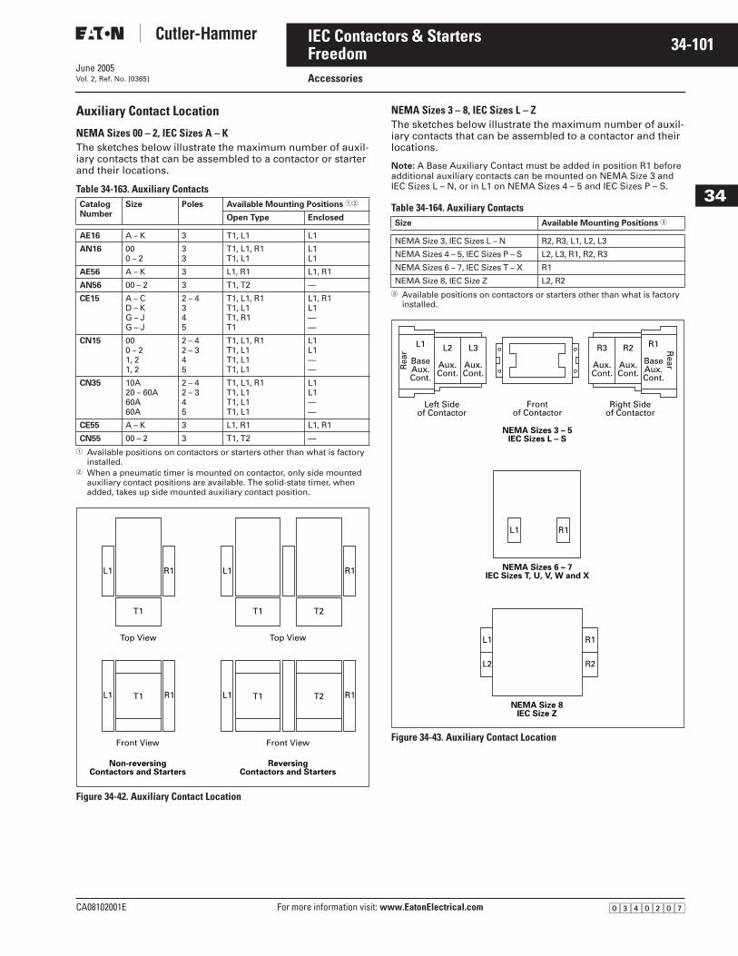
June 2005
CA08102001E For more information visit: www.EatonElectrical.com
34-101IEC Contactors & Starters
34
FreedomAccessoriesVol. 2, Ref. No. [0365]
Auxiliary Contact Location
NEMA Sizes 00 – 2, IEC Sizes A – KThe sketches below illustrate the maximum number of auxil-iary contacts that can be assembled to a contactor or starter and their locations.
Table 34-163. Auxiliary Contacts
� Available positions on contactors or starters other than what is factory installed.
� When a pneumatic timer is mounted on contactor, only side mounted auxiliary contact positions are available. The solid-state timer, when added, takes up side mounted auxiliary contact position.
Figure 34-42. Auxiliary Contact Location
NEMA Sizes 3 – 8, IEC Sizes L – ZThe sketches below illustrate the maximum number of auxil-iary contacts that can be assembled to a contactor and their locations.
Note: A Base Auxiliary Contact must be added in position R1 before additional auxiliary contacts can be mounted on NEMA Size 3 and IEC Sizes L – N, or in L1 on NEMA Sizes 4 – 5 and IEC Sizes P – S.
Table 34-164. Auxiliary Contacts
� Available positions on contactors or starters other than what is factory installed.
Figure 34-43. Auxiliary Contact Location
CatalogNumber
Size Poles Available Mounting Positions ��
Open Type Enclosed
AE16 A – K 3 T1, L1 L1
AN16 000 – 2
33
T1, L1, R1T1, L1
L1L1
AE56 A – K 3 L1, R1 L1, R1
AN56 00 – 2 3 T1, T2 —
CE15 A – CD – KG – JG – J
2 – 4345
T1, L1, R1T1, L1T1, R1T1
L1, R1L1——
CN15 000 – 21, 21, 2
2 – 42 – 345
T1, L1, R1T1, L1T1, L1T1, L1
L1L1——
CN35 10A20 – 60A60A60A
2 – 42 – 345
T1, L1, R1T1, L1T1, L1T1, L1
L1L1——
CE55 A – K 3 L1, R1 L1, R1
CN55 00 – 2 3 T1, T2 —
L1
T1 T2
R1
L1 T1 T2 R1
L1
T1
Top View
Front View
L1 T1 R1
Front View
ReversingContactors and Starters
Non-reversingContactors and Starters
Top View
R1
Size Available Mounting Positions �
NEMA Size 3, IEC Sizes L – N R2, R3, L1, L2, L3
NEMA Sizes 4 – 5, IEC Sizes P – S L2, L3, R1, R2, R3
NEMA Sizes 6 – 7, IEC Sizes T – X R1
NEMA Size 8, IEC Size Z L2, R2
NEMA Sizes 6 – 7IEC Sizes T, U, V, W and X
NEMA Sizes 3 – 5IEC Sizes L – S
NEMA Size 8IEC Size Z
L1 R1
L1
Frontof Contactor
Left Sideof Contactor
L2
Aux.Cont.
L3
Aux.Cont.
R2
Aux.Cont.
R3
Aux.Cont.
L1
BaseAux.Cont.
R1
BaseAux.Cont.
Rea
r Rear
Right Sideof Contactor
R1
L2 R2
�������
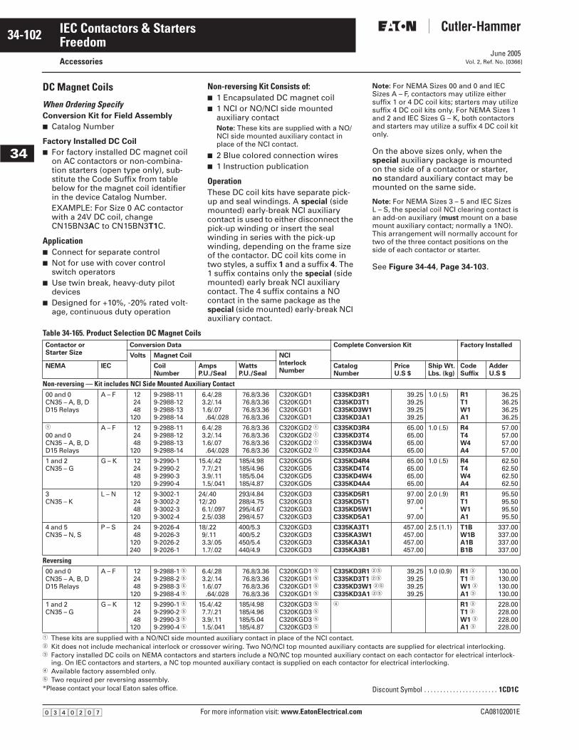
June 2005
34-102
For more information visit: www.EatonElectrical.com CA08102001E
IEC Contactors & Starters
34
FreedomAccessories Vol. 2, Ref. No. [0366]
DC Magnet Coils
When Ordering Specify Conversion Kit for Field Assembly
■ Catalog Number
Factory Installed DC Coil
■ For factory installed DC magnet coil on AC contactors or non-combina-tion starters (open type only), sub-stitute the Code Suffix from table below for the magnet coil identifier in the device Catalog Number.EXAMPLE: For Size 0 AC contactor with a 24V DC coil, change CN15BN3AC to CN15BN3T1C.
Application■ Connect for separate control■ Not for use with cover control
switch operators■ Use twin break, heavy-duty pilot
devices ■ Designed for +10%, -20% rated volt-
age, continuous duty operation
Non-reversing Kit Consists of:■ 1 Encapsulated DC magnet coil■ 1 NCI or NO/NCI side mounted
auxiliary contactNote: These kits are supplied with a NO/NCI side mounted auxiliary contact in place of the NCI contact.
■ 2 Blue colored connection wires■ 1 Instruction publication
OperationThese DC coil kits have separate pick-up and seal windings. A special (side mounted) early-break NCI auxiliary contact is used to either disconnect the pick-up winding or insert the seal winding in series with the pick-up winding, depending on the frame size of the contactor. DC coil kits come in two styles, a suffix 1 and a suffix 4. The 1 suffix contains only the special (side mounted) early break NCI auxiliary contact. The 4 suffix contains a NO contact in the same package as the special (side mounted) early-break NCI auxiliary contact.
Note: For NEMA Sizes 00 and 0 and IEC Sizes A – F, contactors may utilize either suffix 1 or 4 DC coil kits; starters may utilize suffix 4 DC coil kits only. For NEMA Sizes 1 and 2 and IEC Sizes G – K, both contactors and starters may utilize a suffix 4 DC coil kit only.
On the above sizes only, when the special auxiliary package is mounted on the side of a contactor or starter, no standard auxiliary contact may be mounted on the same side.
Note: For NEMA Sizes 3 – 5 and IEC Sizes L – S, the special coil NCI clearing contact is an add-on auxiliary (must mount on a base mount auxiliary contact; normally a 1NO). This arrangement will normally account for two of the three contact positions on the side of each contactor or starter.
See Figure 34-44, Page 34-103.
Table 34-165. Product Selection DC Magnet Coils
� These kits are supplied with a NO/NCI side mounted auxiliary contact in place of the NCI contact.� Kit does not include mechanical interlock or crossover wiring. Two NO/NCI top mounted auxiliary contacts are supplied for electrical interlocking.� Factory installed DC coils on NEMA contactors and starters include a NO/NC top mounted auxiliary contact on each contactor for electrical interlock-
ing. On IEC contactors and starters, a NC top mounted auxiliary contact is supplied on each contactor for electrical interlocking.� Available factory assembled only.� Two required per reversing assembly.*Please contact your local Eaton sales office.
Contactor or Starter Size
Conversion Data Complete Conversion Kit Factory Installed
Volts Magnet Coil NCIInterlockNumber
NEMA IEC CoilNumber
AmpsP.U./Seal
WattsP.U./Seal
CatalogNumber
PriceU.S $
Ship Wt.Lbs. (kg)
CodeSuffix
AdderU.S $
Non-reversing — Kit includes NCI Side Mounted Auxiliary Contact00 and 0CN35 – A, B, DD15 Relays
A – F 122448
120
9-2988-119-2988-129-2988-139-2988-14
6.4/.283.2/.141.6/.07.64/.028
76.8/3.3676.8/3.3676.8/3.3676.8/3.36
C320KGD1C320KGD1C320KGD1C320KGD1
C335KD3R1C335KD3T1C335KD3W1C335KD3A1
39.2539.2539.2539.25
1.0 (.5) R1T1W1A1
36.2536.2536.2536.25
�
00 and 0CN35 – A, B, DD15 Relays
A – F 122448
120
9-2988-119-2988-129-2988-139-2988-14
6.4/.283.2/.141.6/.07.64/.028
76.8/3.3676.8/3.3676.8/3.3676.8/3.36
C320KGD2 �C320KGD2 �C320KGD2 �C320KGD2 �
C335KD3R4C335KD3T4C335KD3W4C335KD3A4
65.0065.0065.0065.00
1.0 (.5) R4T4W4A4
57.0057.0057.0057.00
1 and 2CN35 – G
G – K 122448
120
9-2990-19-2990-29-2990-39-2990-4
15.4/.427.7/.213.9/.111.5/.041
185/4.98185/4.96185/5.04185/4.87
C320KGD5C320KGD5C320KGD5C320KGD5
C335KD4R4C335KD4T4C335KD4W4C335KD4A4
65.0065.0065.0065.00
1.0 (.5) R4T4W4A4
62.5062.5062.5062.50
3CN35 – K
L – N 122448
120
9-3002-19-3002-29-3002-39-3002-4
24/.4012/.206.1/.0972.5/.038
293/4.84288/4.75295/4.67298/4.57
C320KGD3C320KGD3C320KGD3C320KGD3
C335KD5R1C335KD5T1C335KD5W1C335KD5A1
97.0097.00
*97.00
2.0 (.9) R1T1W1A1
95.5095.5095.5095.50
4 and 5CN35 – N, S
P – S 2448
120240
9-2026-49-2026-39-2026-29-2026-1
18/.229/.113.3/.051.7/.02
400/5.3400/5.2450/5.4440/4.9
C320KGD3C320KGD3C320KGD3C320KGD3
C335KA3T1C335KA3W1C335KA3A1C335KA3B1
457.00457.00457.00457.00
2.5 (1.1) T1BW1BA1BB1B
337.00337.00337.00337.00
Reversing00 and 0CN35 – A, B, DD15 Relays
A – F 122448
120
9-2988-1 �9-2988-2 �9-2988-3 �9-2988-4 �
6.4/.283.2/.141.6/.07.64/.028
76.8/3.3676.8/3.3676.8/3.3676.8/3.36
C320KGD1 �C320KGD1 �C320KGD1 �C320KGD1 �
C335KD3R1 ��
C335KD3T1 ��
C335KD3W1 ��
C335KD3A1 ��
39.2539.2539.2539.25
1.0 (0.9) R1 �
T1 �
W1 �
A1 �
130.00130.00130.00130.00
1 and 2CN35 – G
G – K 122448
120
9-2990-1 �9-2990-2 �9-2990-3 �9-2990-4 �
15.4/.427.7/.213.9/.111.5/.041
185/4.98185/4.96185/5.04185/4.87
C320KGD3 �C320KGD3 �C320KGD3 �C320KGD3 �
� R1 �
T1 �
W1 �
A1 �
228.00228.00228.00228.00
Discount Symbol . . . . . . . . . . . . . . . . . . . . . . . 1CD1C
�������
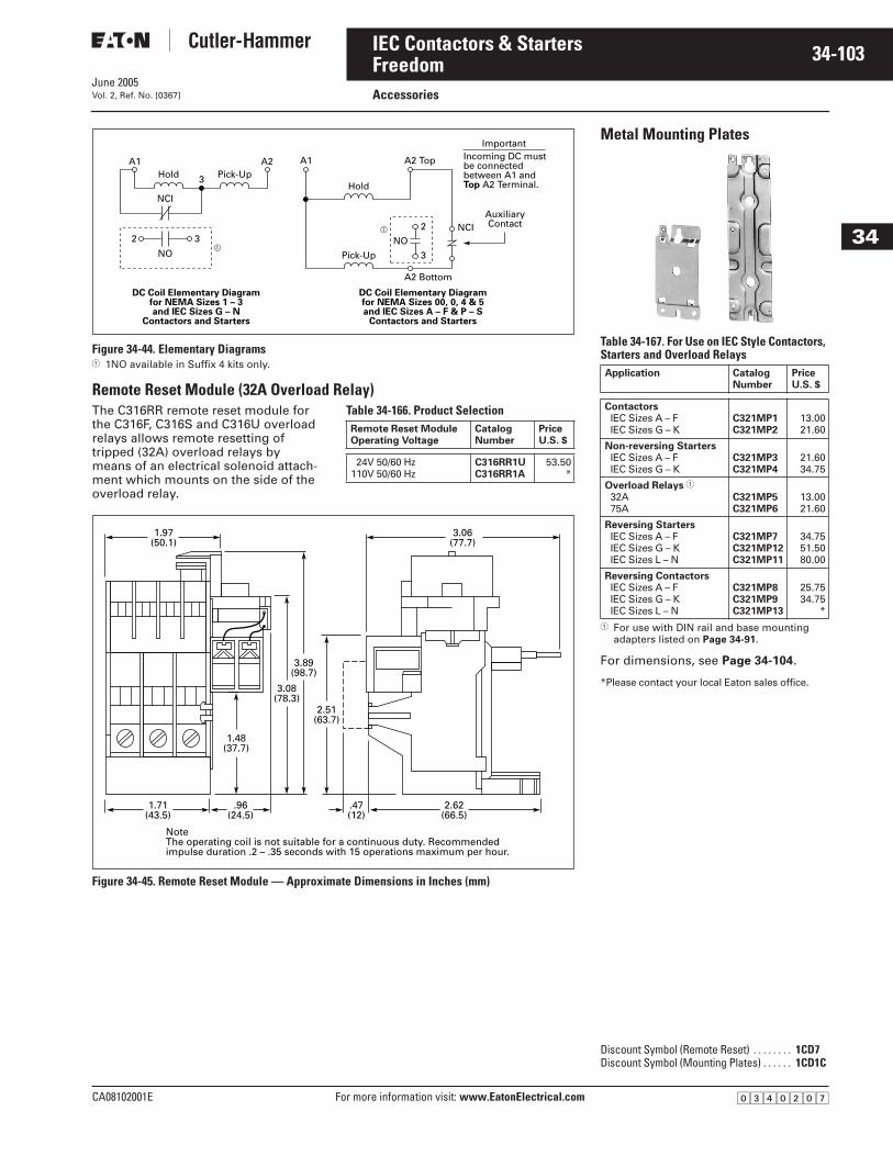
CA08102001E For more information visit: www.EatonElectrical.com
34-103IEC Contactors & Starters
June 2005
34
FreedomAccessories Vol. 2, Ref. No. [0367]
Figure 34-44. Elementary Diagrams � 1NO available in Suffix 4 kits only.
Remote Reset Module (32A Overload Relay)The C316RR remote reset module for the C316F, C316S and C316U overload relays allows remote resetting of tripped (32A) overload relays by means of an electrical solenoid attach-ment which mounts on the side of the overload relay.
Table 34-166. Product Selection
Figure 34-45. Remote Reset Module — Approximate Dimensions in Inches (mm)
AuxiliaryContact
ImportantIncoming DC mustbe connectedbetween A1 andTop A2 Terminal.
A1 A2 A1 A2 Top
A2 Bottom
3
NCI
NO�
�
32
3
NCINO2
Hold Pick-UpHold
Pick-Up
DC Coil Elementary Diagramfor NEMA Sizes 1 – 3and IEC Sizes G – N
Contactors and Starters
DC Coil Elementary Diagramfor NEMA Sizes 00, 0, 4 & 5and IEC Sizes A – F & P – S
Contactors and Starters
Remote Reset ModuleOperating Voltage
CatalogNumber
PriceU.S. $
24V 50/60 Hz110V 50/60 Hz
C316RR1UC316RR1A
53.50*
3.06(77.7)
2.62(66.5)
1.71(43.5)
.96(24.5)
.47(12)
1.97(50.1)
2.51(63.7)
3.08(78.3)
3.89(98.7)
1.48(37.7)
NoteThe operating coil is not suitable for a continuous duty. Recommendedimpulse duration .2 – .35 seconds with 15 operations maximum per hour.
Metal Mounting Plates
Table 34-167. For Use on IEC Style Contactors, Starters and Overload Relays
� For use with DIN rail and base mounting adapters listed on Page 34-91.
For dimensions, see Page 34-104.
*Please contact your local Eaton sales office.
Application CatalogNumber
PriceU.S. $
ContactorsIEC Sizes A – FIEC Sizes G – K
C321MP1C321MP2
13.0021.60
Non-reversing StartersIEC Sizes A – FIEC Sizes G – K
C321MP3C321MP4
21.6034.75
Overload Relays �32A75A
C321MP5C321MP6
13.0021.60
Reversing StartersIEC Sizes A – FIEC Sizes G – KIEC Sizes L – N
C321MP7C321MP12C321MP11
34.7551.5080.00
Reversing ContactorsIEC Sizes A – FIEC Sizes G – KIEC Sizes L – N
C321MP8C321MP9C321MP13
25.7534.75
*
Discount Symbol (Remote Reset) . . . . . . . . 1CD7Discount Symbol (Mounting Plates) . . . . . . 1CD1C
�������
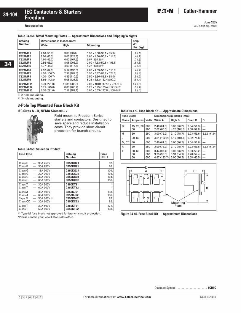
June 2005
34-104
For more information visit: www.EatonElectrical.com CA08102001E
IEC Contactors & Starters
34
FreedomAccessories Vol. 2, Ref. No. [0368]
Table 34-168. Metal Mounting Plates — Approximate Dimensions and Shipping Weights
� 2-hole mounting.� 3-hole mounting.
3-Pole Top Mounted Fuse Block KitIEC Sizes A – K, NEMA Sizes 00 – 2
Field mount to Freedom Series starters and contactors. Designed to save space and reduce installation costs. They provide short circuit protection for branch circuits.
Table 34-169. Selection Product
� Type M fuse block not approved for branch circuit protection.*Please contact your local Eaton sales office.
Table 34-170. Fuse Block Kit — Approximate Dimensions
Figure 34-46. Fuse Block Kit — Approximate Dimensions
CatalogNumber
Dimensions in Inches (mm) ShipWt.Lbs. (kg)
Wide High Mounting
C321MP1C321MP2C321MP3C321MP4C321MP5
2.00 (50.8)2.56 (65.0)1.80 (45.7)2.56 (65.0)1.77 (45.0)
3.88 (98.6)5.05 (128.3)6.60 (167.6)8.08 (205.2)4.63 (117.6)
1.50 x 3.38 (38.1 x 85.9)2.00 x 4.50 (50.8 x 114.3)6.07 (154.2) �2.00 x 7.63 (50.8 x 193.8)4.27 (108.5) �
.2 (.1)
.4 (.2)
.7 (.3)
.6 (.3)
.3 (.1)
C321MP6C321MP7C321MP8C321MP9
2.52 (64.0)4.20 (106.7)4.20 (106.7)5.66 (143.8)
5.14 (130.6)7.38 (187.5)4.35 (110.5)5.05 (128.3)
2.00 x 4.59 (50.8 x 116.6)3.50 x 6.87 (88.9 x 174.5)3.50 x 3.86 (88.9 x 98.0)5.25 x 3.63 (133.4 x 92.2)
.4 (.2)
.8 (.4)
.5 (.2)
.8 (.4)
C321MP11C321MP12C321MP13
8.70 (221.0)5.71 (145.0)8.70 (221.0)
11.35 (288.3)8.08 (205.2)7.17 (182.1)
7.00 x 10.81 (177.8 x 274.6) �5.25 x 6.75 (133.4 x 171.5) �7.00 x 6.63 (177.8 x 168.4) �
1.2 (.5).9 (.4).9 (.4)
Fuse Type CatalogNumber
PriceU.S. $
Class HClass R
——
30A 250V30A 250V
C350KH21C350KR21
82.96.
Class GClass GClass GClass G
————
15A 300V20A 300V30A 300V60A 300V
C350KG37C350KG38C350KG31C350KG32
104.104.104.156.
Class TClass T
——
30A 300V60A 300V
C350KT31C350KT32
**
Class JClass JType MClass CC
————
30A 600V60A 600V30A 600V �30A 600V
C350KJ61C350KJ62C350KM61C350KC63
133.156.82.82.
Class TClass T
——
30A 600V60A 600V
C350KT61C350KT62
121.133.
Fuse Block Dimensions in Inches (mm)
Class Amperes Volts Wide A High B Deep C D
G 15, 20, 3060
300300
2.40 (61.0)2.62 (66.5)
3.00 (76.2)4.25 (108.0)
2.04 (51.8)2.08 (52.8)
——
H 30 250 3.00 (76.2) 3.10 (78.7) 2.23 (56.6) 3.62 (91.9)
J 30, 60 600 4.81 (122.2) 4.12 (104.6) 2.82 (71.6) —
M, CC 30 600 2.40 (61.0) 3.00 (76.2) 2.04 (51.8) —
R 30 250 3.00 (76.2) 3.10 (78.7) 2.23 (56.6) 3.62 (91.9)
T 30, 603060
300600600
3.44 (87.4)3.75 (95.3)4.87 (123.7)
3.00 (76.2)3.31 (84.1)3.00 (76.2)
2.33 (59.2)2.26 (57.4)2.58 (65.5)
———
Discount Symbol . . . . . . . . . . . . . . . . . . . . . . . 1CD1C
A C
MountingPlate
D
B
�������
June 2005
CA08102001E For more information visit: www.EatonElectrical.com
34-105IEC Contactors & Starters
34
FreedomAccessories Vol. 2, Ref. No. [0369]
Mechanical Interlock and Reversing KitsMechanical interlocks and reversing kits are designed for field assembly of reversing contactors or starters from Free-dom Series components. The Reversing Kits include a Mechanical Interlock, stabilizer bar and a pre-cut, trimmed and formed wire set. Auxiliary contacts, if required, must be ordered separately. See Page 34-100.
Table 34-171. Reversing Kits (Horizontal Contactor Mounting Only)
� Kit includes (2) NC auxiliary contacts.
Table 34-172. Mechanical Interlock Only ��
� Without cross-wiring.� For use with latest series product.
Solid-State Timers
Solid-State ON DELAY Timer — Side Mounted on Freedom Series NEMA 00 – 2, IEC A – K and C25D, C25E and C25F Frame
This timer is designed to be wired in SERIES with the load (typically a coil). When the START button is pushed (power applied to timer), the ON DELAY timing function starts. At the completion of the set timing period, timer and series wired load will both be energized.
Table 34-173. Product Selection — Mounted Timer
� Add operating voltage Suffix to Catalog Number. A = 120V, B = 240V, E = 208V
� Rated .5 ampere pilot duty – not to be used on larger contactors.� Terminal connections are quick connects only. Two per side.
Shorting Bar KitsThese kits provide phase-to-phase power connections of contactors for field assembly. The kits include bus connec-tions and mounting hardware. The shorting bars connect all three phases of a single contactor.
Table 34-174. Product Selection
Pneumatic Timers — Top MountedAttachment mounts on top of any NEMA Size 00 – 2 or IEC Size A – K Freedom Series starter or contactor (top mounted auxiliary contacts can not be installed on device when timer is used). Timer unit has 1NO-1NC isolated timed
contacts — circuits in each pole must be the same polarity. Units are convertible from OFF to ON DELAY or vice-versa.
Table 34-175. Maximum Ampere Ratings
Table 34-176. Product Selection
*Please contact your local Eaton sales office.
Application CatalogNumber
PriceU.S. $NEMA Size IEC Size
000123
A – CD – F—G – K—
C321KM60K14BC321KM60K13BC321KM60K15BC321KM60K16BC321KM60K17 �
43.0043.0065.0065.0086.50
——45—
L and MN——P – S
C321KM60K21 �
C321KM60K18 �
C321KM60K19 �
C321KM60K20 �
C321KM60K44 �
86.5086.5086.5086.5086.50
Application CatalogNumber
PriceU.S. $NEMA Size IEC Size Contactor
Mounting
00 – 2 A – K Horizontal C321KM60B 19.30
3 L – N Horizontal C321KM30 65.00
3 to 4 N to P Horizontal C321KM43 70.50
4 P – S Horizontal C321KM40 65.00
4 to 5 — Horizontal C321KM45 65.00
4 to 6 S to T/U Horizontal C321KM80 86.50
5 — Horizontal C321KM50 65.00
5 to 6 — Horizontal C321KM56 *
6 T and U Horizontal C321KM70 86.50
6 to 7 T/U to V – X Horizontal C321KM90 86.50
7 V, W and X Horizontal C321KM34 331.00
4 or 5 to 5 P – S to 5 Vertical C321KM55 63.00
5 to 6 — Vertical C321KM65 70.50
6 T and U Vertical C321KM66 83.00
6 to 7 T/U to V – X Vertical C321KM67 *
Cat. No.C321KM60B
Part No.23-7165
Wire Set
Timing Range CatalogNumber ���
PriceU.S. $
.1 – 1.0 Seconds1 – 30 Seconds
30 – 300 Seconds5 – 30 Minutes
C320TDN1_C320TDN30_C320TDN300_C320TDN2000_
109.00109.00109.00
*
Description CatalogNumber
PriceU.S. $
NEMA Size 3, IEC Sizes L – NNEMA Size 4, IEC Sizes P – SNEMA Size 5NEMA Size 6, IEC Sizes T and U
C321SB18C321SB19C321SB21C321SB22
21.6025.75
**
Description Volts AC
120 240 480 600
MakeBreak
303
151.5
7.5.75
6.6
Timing Range CatalogNumber
PriceU.S. $
.1 to 30 Seconds10 to 180 Seconds
C320TP1C320TP2
207.00207.00
Discount Symbol . . . . . . . . . . . . . . . . . . . . . . . 1CD1C
�������
June 2005
34-106
For more information visit: www.EatonElectrical.com CA08102001E
IEC Contactors & Starters
34
FreedomAccessories Vol. 2, Ref. No. [0370]
Locking Cover for Overload Relay — C306 OnlySnap-on transparent or opaque plastic panel for covering access port to the over-load relay trip setting dial — helps prevent accidental or unauthorized changes to trip and reset setting.
Table 34-177. Product Selection
Control Circuit Fuse BlockThese panel mounted fuse holders, designed for control circuit protec-tion or other similar low current requirements, have extractor type fuse
caps. The Class CC rejection type fuses (KTK-R) used in these holders are intended for use with equipment designated as being suitable for use on systems having high available fault currents. If branch circuit protective device is 45A or greater, C320FBR fuse kit may be required for control circuit protection per NEC 430-72.
Table 34-178. Product Selection
� A fuse is not supplied, but holder will accept a Bussman Type KTK or KTK-R (13/32" x 1-1/2") fuse, 600V maximum.
� Includes a 5A, 600V KTK-R fuse.
Figure 34-47. Approximate Dimensions in Inches (mm)
DIN Rail Mounting Channel — 35 mm Designed for DIN rail mounting of IEC style contactors and starters.
DIN Rail
Table 34-179. Product Selection
Finger Protection ShieldsSnap-on shields for both contactors and starters provide IEC Type IP20 Finger Protection. Prevents accidental contact with line/load terminals.
Table 34-180. Product Selection
*Please contact your local Eaton sales office.
Description Min. OrderingQty. (Std. Pkg.)
CatalogNumber
PriceU.S. $
Clear cover, no accessibility 50 C320PC3 1.15
Gray cover, no accessibility, with Auto only nib
50 C320PC4 1.15
Gray cover, no accessibility, with Manual only nib
50 C320PC5 1.15
Gray cover with FLA dial accessibility, A, B, C, D positions an Auto only nib
50 C320PC6 *
Gray cover with FLA dial accessibility, A, B, C, D positions and Manual only nib
50 C320PC7 1.15
Type Max.Amperes
CatalogNumber
PriceU.S. $
Fuse HolderOnly
1530
C320FB �
C320FBR �21.6043.00
.97(24.6)
1.25 (31.8)1.88 (47.8)
1.19(30.2)
.88(22.4)
2.06(52.3)
Fuse
Description CatalogNumber
PriceU.S. $
1 Meter Length MC382MA1 8.65
Application CatalogNumber
PriceU.S. $
NEMA Size 00,IEC Sizes A – C
NEMA Size 0,IEC Sizes D – F
C320LS1
C320LS2
4.45
4.45
NEMA Sizes 1 – 2, IEC Sizes G – K
ContactorsReversing Contactors
C320LS3C320LS4
5.908.65
NEMA Size 1StartersReversing Starters
C320LS5C320LS6
5.90*
NEMA Size 2, IEC Sizes G – K
StartersReversing Starters
C320LS7C320LS8
5.90*
Adapter to DIN Rail Mount NEMA 1 – 2 and IEC G – K ContactorsDesigned to allow DIN rail mounting of NEMA 1 – 2 and IEC G – K contactors. Includes all hardware required to con-vert contactors from panel mounting to 35 mm DIN rail mounting.
Table 34-181. Product Selection
Transient Suppressor KitsNEMA Sizes 00 – 2, IEC Sizes A – K
These kits limit high voltage transients pro-duced in the control circuit when power is removed from the con-tactor or starter coil. There are three sepa-rate suppressors for use on 24 – 120V, 208 – 240V or 277 – 480V coils respectively.
These devices mount directly to the coil terminals of Freedom Series con-tactors or starters NEMA Sizes 00 – 2, IEC Sizes A – K and lighting contactors 10 – 60A. Reversing devices will require two.
Table 34-182. Product Selection
� Suppressor is compatible with coil voltages/ranges as shown, 50 and 60 Hz.
NEMA Sizes 3 – 5, IEC Sizes L – SThis device mounts on top of any side mounted auxiliary contact on Freedom Series NEMA Sizes 3 – 5, IEC Sizes L – S and lighting con-
tactors 100 – 300A. It connects across coil terminals on any 120V contactor or starter magnet coil (reversing start-ers or contactors require 2).
Limits high voltage transients pro-duced in the circuit when power is removed from the coil.
Table 34-183. Product Selection
CatalogNumber
PriceU.S. $
C320DN65 24.00
Description Coil Voltage50/60 Hz �
CatalogNumber
PriceU.S. $
TransientSuppressor
24 – 120V208 – 240V277 – 480V
C320TS1C320TS2C320TS3
51.5051.5051.50
Description CoilVoltage
CatalogNumber
PriceU.S. $
TransientSuppressor
120V C320AS1 74.50
Discount Symbol . . . . . . . . . . . . . . . . . . . . . . . 1CD1C
Cat. No.C320TS2
�������
June 2005
CA08102001E For more information visit: www.EatonElectrical.com
34-107IEC Contactors & Starters
34
FreedomAccessories Vol. 2, Ref. No. [0371]
DC/AC Interface ModuleThe Catalog Number C320DC Interface Module is an optically isolated solid-state switch which provides a means of operating AC coils with a 5 – 48V DC control signal. It acts as a space saving interposing relay which
can switch a specified 50/60 Hz AC source to the contactor or starter coil.
The module may be directly attached to the coil terminals of any Freedom Series contactor or starter — NEMA Sizes 00 – 3, IEC Sizes A – N and light-ing contactors 10 – 100A. It also has provisions for DIN rail mounting.
The module will operate coils within the voltage ranges shown below.
Design Characteristics■ DC Input: 5 – 48V DC ±10% at
mA nominal■ AC Operating Voltage: 240V AC
max. (360 VA) ±10% 50/60 Hz■ DC Operating Voltage: 30V DC max.
(5A)■ AC Current Rating:
❑ 10A make (inrush) ❑ 1A break (sealed)
Table 34-184. Controller Coil Voltage Ranges
Figure 34-48. Typical Application
Table 34-185. Product Selection
Controller CatalogNumber Prefix
ControllerSize or Rating
Coil RangeVolts AC
AE16, AE17, AE56, AE57, CE15, CE55
A – FG – KL – N
24 – 24048 – 240
110 – 240
AN16, AN56, CN15, CN55
00 – 01 – 23
24 _ 24048 – 240
110 – 240
CN35 10 – 30A60A
100A
24 – 24048 – 240
110 – 240
CoilVoltage
CatalogNumber
PriceU.S. $
6V DC9V DC
C320DC2V6C320DC2V9
**
12V DC24V DC48V DC
C320DC2V12C320DC2V24C320DC2V48
***
Cat. No.C320DC
5 – 48V DC InputObservePolarity
on Module
24 – 240V AC50/60 Hz
Contactor Coil
Solid-State Switch
Adhesive Dust Cover
NEMA Sizes 00 – 2, IEC Sizes A – KThese adhesive stickers come 25 to a package and provide extra protection from contaminants when applied to the sides of Freedom NEMA Sizes 00 – 2 and IEC Sizes A – K. Adhesive covers are easily applied to side open-ing where auxiliaries are not installed
and provide extra protection from metal filings and other debris.
Table 34-186. Product Selection
Add-On Power Pole Kit
NEMA Sizes 00 – 2, IEC A – KThis device mounts on the side of Freedom NEMA Size 00 – 2 and IEC Size A – K contactors. One unit can be mounted on each side and carries UL, cUL and IEC rat-ings. The device is rated for resistive, inductive and lighting applications.
Table 34-187. Product Selection — Add-On Power Pole Kit
Special ModificationsTable 34-188. For Catalog Numbers AE16, AE17, AN16, AE56, AE57, AN56, CE15, CN15, CN35, CE55, CN55
� These modifications are generally available in Kit form at lower cost. See specific product sections for Kit listings.
� Consult factory for price. *Please contact your local Eaton sales office.
CatalogNumber
PriceU.S. $
C320DSTCVR (25 to a package) *
UL Ampere Rating IEC 947 Ampere Rating 1NOPowerPoleCatalogNumber
PriceU.S. $Inductive
600VResistive600V
hp1-Phase
LockedRotor 240V
LightingBallastTungsten480V
AC-1 600V
AC-3 600V
AC-5aAC-5b480V115V 230V
15 20 1/2 2 96 20 20 12 18 C320PPD10 36.25
Addition or Special Feature Starter Size and Price Adder (U.S. $) — NEMA/IEC
00/A – C
0/D – F
1—
2/G – K
3/L – N
4/P – S
5/T – U
6/V
7/W, X
8/Z
Control CircuitExtra Auxiliary Circuit, Factory Installed NO or NC — each contact �
�
Transient Suppressor � �
Power CircuitContactor/Starter for Ring Lug Capability — Add Mod Code T16 to Catalog Number (Power Terminals Only, Control Termi-nals as Standard) Stand-Alone Overload Relays Cannot Accept Ring Lugs on Line Side.
�
Factory Installed Dust CoversFactory Installed C320DSTCVR – Add Mod Code -53 to Catalog Number �
� NA NA NA NA NA NA
Discount Symbol . . . . . . . . . . . . . . . . . . . . . . . 1CD1C
�������
June 2005
34-108
For more information visit: www.EatonElectrical.com CA08102001E
IEC Contactors & Starters
34
Freedom Renewal Parts Vol. 2, Ref. No. [0372]
Table 34-189. For Catalog Numbers AE16, AE17, AE56, AE57, CE15 and CE55 — IEC Frames A – F
� Non-encapsulated coils. � Replace with complete contactor. *Please contact your local Eaton sales office.
Description IEC FramesA – F
PriceU.S. $
IEC FramesA – C �
PriceU.S. $
IEC FramesD – F �
PriceU.S. $
Series A1 Series B1 Series C1 Series B1 Series C1
Part No. Part No. Part No. Part No. Part No.
Renewal Parts Publication Number None None None None None
Contact Kits2-Pole . . . . . . . . . . . . . . . . . . . . . . . . . . . . .3-Pole . . . . . . . . . . . . . . . . . . . . . . . . . . . . .4-Pole . . . . . . . . . . . . . . . . . . . . . . . . . . . . .5-Pole . . . . . . . . . . . . . . . . . . . . . . . . . . . . .
�
�
�
�
————
�
�
�
�
�
�
�
�
————
�
�
�
�
�
�
�
�
————
Magnet Coils Coil Suffix120V 60 Hz or 110V 50 Hz240V 60 Hz or 220V 50 Hz480V 60 Hz or 440V 50 Hz600V 60 Hz or 550V 50 Hz
ABCD
9-2650-19-2650-29-2650-39-2650-4
86.86.86.
*
9-2875-19-2875-29-2875-39-2875-4
9-2875-19-2875-29-2875-39-2875-4
86.86.86.86.
9-2876-19-2876-29-2876-39-2876-4
9-2876-19-2876-29-2876-39-2876-4
86.86.86.86.
208V 60 Hz . . . . . . . . . . . . .277V 60 Hz . . . . . . . . . . . . .208/240V 60 Hz . . . . . . . . . .240V 50 Hz . . . . . . . . . . . . .380 – 415V 50 Hz . . . . . . . . .
EHJKL
9-2650-59-2650-13—9-2650-129-2650-6
86.86.—*
86.
9-2875-59-2875-129-2875-379-2875-119-2875-6
9-2875-59-2875-129-2875-379-2875-119-2875-6
86.86.86.86.86.
9-2876-59-2876-129-2876-379-2876-119-2876-6
9-2876-19-2876-29-2876-379-2876-39-2876-4
86.86.86.86.86.
24V 60 Hz – 24V 50 Hz24V 60 Hz . . . . . . . . . . . . . . .24V 50 Hz . . . . . . . . . . . . . . .32V 50 Hz . . . . . . . . . . . . . . .48V 60 Hz . . . . . . . . . . . . . . .48V 50 Hz . . . . . . . . . . . . . . .
TTUVWY
—9-2650-79-2650-149-2650-99-2650-89-2650-10
—86.86.
***
9-2875-36—9-2875-139-2875-169-2875-89-2875-9
9-2875-36—9-2875-139-2875-169-2875-89-2875-9
86.—
86.86.86.86.
9-2876-36—9-2876-139-2876-169-2876-89-2876-9
9-2876-36—9-2876-139-2876-169-2876-89-2876-9
86.—
86.86.86.86.
Overload RelaysFor replacement on existing starters: 3-Pole — AmbientCompensated Bimetallic . . . . . . . . . . . . C306DN3B 90. C306DN3B C306DN3B 90. C306DN3B C306DN3B 90.
Current TransformerTransformer. . . . . . . . . . . . . . . . . . . . . . . . — — — — — — — —
Magnet Frame Armature Lower Magnet Frame. . . . . . . . . . . . . . . .Upper Magnet Frame. . . . . . . . . . . . . . . .
�
�——
�
�
�
�——
�
�
�
�——
Discount Symbol . . . . . . . . . . . . . . . . . . . . . . . 1CD1C
�������
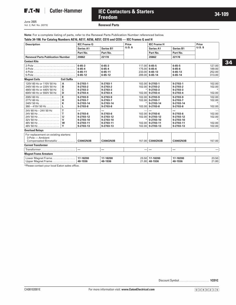
June 2005
CA08102001E For more information visit: www.EatonElectrical.com
34-109IEC Contactors & Starters
34
FreedomRenewal PartsVol. 2, Ref. No. [0373]
Note: For a complete listing of parts, refer to the Renewal Parts Publication Number referenced below.
Table 34-190. For Catalog Numbers AE16, AE17, AE56, AE57, CE15 and CE55 — IEC Frames G and H
*Please contact your local Eaton sales office.
Description IEC Frame G PriceU.S. $
IEC Frame H PriceU.S. $Series A1 Series B1 Series A1 Series B1
Part No. Part No. Part No. Part No.
Renewal Parts Publication Number 20862 22178 20862 22178
Contact Kits2-Pole . . . . . . . . . . . . . . . . . . . . . . . . . . . . .3-Pole . . . . . . . . . . . . . . . . . . . . . . . . . . . . .4-Pole . . . . . . . . . . . . . . . . . . . . . . . . . . . . .5-Pole . . . . . . . . . . . . . . . . . . . . . . . . . . . . .
6-65-36-65-46-65-116-65-12
6-65-36-65-46-65-116-65-12
117.00175.00233.00289.00
6-65-56-65-66-65-136-65-14
6-65-56-65-66-65-136-65-14
127.00189.00252.00313.00
Magnet Coils Coil Suffix120V 60 Hz or 110V 50 Hz240V 60 Hz or 220V 50 Hz480V 60 Hz or 440V 50 Hz600V 60 Hz or 550V 50 Hz
ABCD
9-2703-19-2703-29-2703-39-2703-4
9-2703-19-2703-29-2703-39-2703-4
102.00102.00
*102.00
9-2703-19-2703-29-2703-39-2703-4
9-2703-19-2703-29-2703-39-2703-4
102.00102.00
*102.00
208V 60 Hz . . . . . . . . . . . . . .277V 60 Hz . . . . . . . . . . . . . .240V 50 Hz . . . . . . . . . . . . . .380 – 415V 50 Hz . . . . . . . . .
EHKL
9-2703-99-2703-79-2703-149-2703-8
9-2703-99-2703-79-2703-149-2703-8
102.00102.00
*102.00
9-2703-99-2703-79-2703-149-2703-8
9-2703-99-2703-79-2703-149-2703-8
102.00102.00
*102.00
24V 60 Hz – 24V 50 Hz24V 60 Hz . . . . . . . . . . . . . . .24V 50 Hz . . . . . . . . . . . . . . .32V 50 Hz . . . . . . . . . . . . . . .48V 60 Hz . . . . . . . . . . . . . . .48V 50 Hz . . . . . . . . . . . . . . .
TTUVWY
—9-2703-69-2703-129-2703-109-2703-119-2703-13
—9-2703-69-2703-129-2703-109-2703-119-2703-13
—102.00102.00
*102.00102.00
—9-2703-69-2703-129-2703-109-2703-119-2703-13
—9-2703-69-2703-129-2703-109-2703-119-2703-13
—102.00102.00
*102.00102.00
Overload RelaysFor replacement on existing starters: 3-Pole — AmbientCompensated Bimetallic . . . . . . . . . . . . C306GN3B C306GN3B 157.00 C306GN3B C306GN3B 157.00
Current TransformerTransformer . . . . . . . . . . . . . . . . . . . . . . . . — — — — — —
Magnet Frame ArmatureLower Magnet Frame . . . . . . . . . . . . . . . .Upper Magnet Frame . . . . . . . . . . . . . . . .
17-1820048-1936
17-1820048-1936
23.5021.80
17-1820048-1936
17-1820048-1936
23.5021.80
Discount Symbol . . . . . . . . . . . . . . . . . . . . . . . 1CD1C
�������
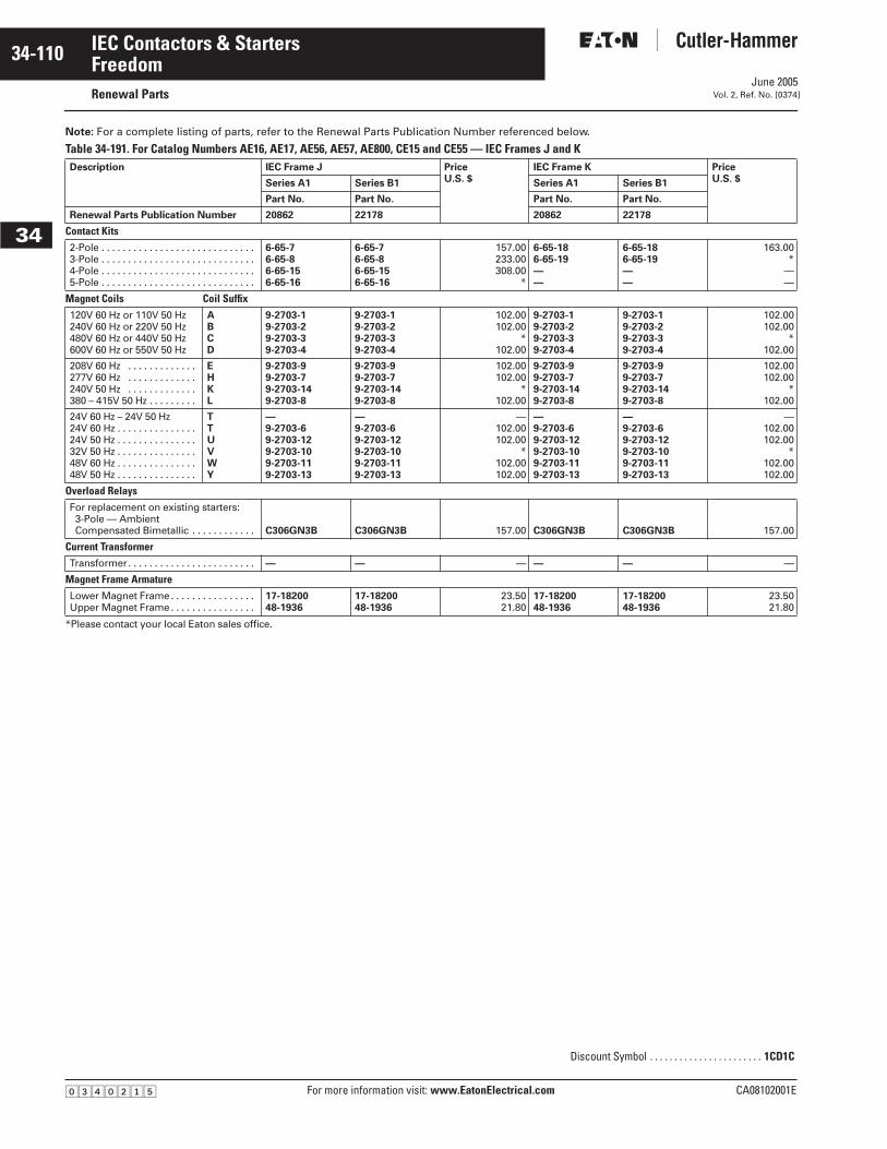
June 2005
34-110
For more information visit: www.EatonElectrical.com CA08102001E
IEC Contactors & Starters
34
FreedomRenewal Parts Vol. 2, Ref. No. [0374]
Note: For a complete listing of parts, refer to the Renewal Parts Publication Number referenced below.
Table 34-191. For Catalog Numbers AE16, AE17, AE56, AE57, AE800, CE15 and CE55 — IEC Frames J and K
*Please contact your local Eaton sales office.
Description IEC Frame J PriceU.S. $
IEC Frame K PriceU.S. $Series A1 Series B1 Series A1 Series B1
Part No. Part No. Part No. Part No.
Renewal Parts Publication Number 20862 22178 20862 22178
Contact Kits2-Pole . . . . . . . . . . . . . . . . . . . . . . . . . . . . .3-Pole . . . . . . . . . . . . . . . . . . . . . . . . . . . . .4-Pole . . . . . . . . . . . . . . . . . . . . . . . . . . . . .5-Pole . . . . . . . . . . . . . . . . . . . . . . . . . . . . .
6-65-76-65-86-65-156-65-16
6-65-76-65-86-65-156-65-16
157.00233.00308.00
*
6-65-186-65-19——
6-65-186-65-19——
163.00*
——
Magnet Coils Coil Suffix120V 60 Hz or 110V 50 Hz240V 60 Hz or 220V 50 Hz480V 60 Hz or 440V 50 Hz600V 60 Hz or 550V 50 Hz
ABCD
9-2703-19-2703-29-2703-39-2703-4
9-2703-19-2703-29-2703-39-2703-4
102.00102.00
*102.00
9-2703-19-2703-29-2703-39-2703-4
9-2703-19-2703-29-2703-39-2703-4
102.00102.00
*102.00
208V 60 Hz . . . . . . . . . . . . .277V 60 Hz . . . . . . . . . . . . .240V 50 Hz . . . . . . . . . . . . .380 – 415V 50 Hz . . . . . . . . .
EHKL
9-2703-99-2703-79-2703-149-2703-8
9-2703-99-2703-79-2703-149-2703-8
102.00102.00
*102.00
9-2703-99-2703-79-2703-149-2703-8
9-2703-99-2703-79-2703-149-2703-8
102.00102.00
*102.00
24V 60 Hz – 24V 50 Hz24V 60 Hz . . . . . . . . . . . . . . .24V 50 Hz . . . . . . . . . . . . . . .32V 50 Hz . . . . . . . . . . . . . . .48V 60 Hz . . . . . . . . . . . . . . .48V 50 Hz . . . . . . . . . . . . . . .
TTUVWY
—9-2703-69-2703-129-2703-109-2703-119-2703-13
—9-2703-69-2703-129-2703-109-2703-119-2703-13
—102.00102.00
*102.00102.00
—9-2703-69-2703-129-2703-109-2703-119-2703-13
—9-2703-69-2703-129-2703-109-2703-119-2703-13
—102.00102.00
*102.00102.00
Overload RelaysFor replacement on existing starters: 3-Pole — AmbientCompensated Bimetallic . . . . . . . . . . . . C306GN3B C306GN3B 157.00 C306GN3B C306GN3B 157.00
Current TransformerTransformer. . . . . . . . . . . . . . . . . . . . . . . . — — — — — —
Magnet Frame ArmatureLower Magnet Frame. . . . . . . . . . . . . . . .Upper Magnet Frame. . . . . . . . . . . . . . . .
17-1820048-1936
17-1820048-1936
23.5021.80
17-1820048-1936
17-1820048-1936
23.5021.80
Discount Symbol . . . . . . . . . . . . . . . . . . . . . . . 1CD1C
�������
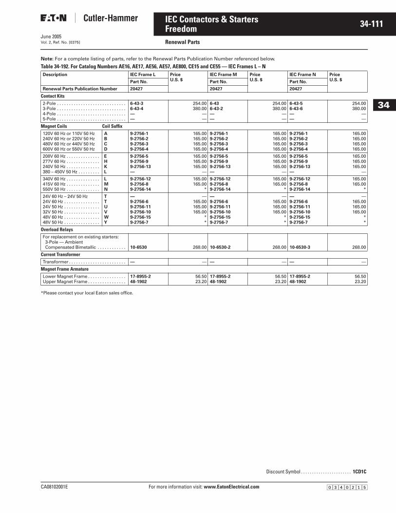
June 2005
CA08102001E For more information visit: www.EatonElectrical.com
34-111IEC Contactors & Starters
34
FreedomRenewal PartsVol. 2, Ref. No. [0375]
Note: For a complete listing of parts, refer to the Renewal Parts Publication Number referenced below.
Table 34-192. For Catalog Numbers AE16, AE17, AE56, AE57, AE800, CE15 and CE55 — IEC Frames L – N
*Please contact your local Eaton sales office.
Description IEC Frame L PriceU.S. $
IEC Frame M PriceU.S. $
IEC Frame N PriceU.S. $Part No. Part No. Part No.
Renewal Parts Publication Number 20427 20427 20427
Contact Kits2-Pole . . . . . . . . . . . . . . . . . . . . . . . . . . . . .3-Pole . . . . . . . . . . . . . . . . . . . . . . . . . . . . .4-Pole . . . . . . . . . . . . . . . . . . . . . . . . . . . . .5-Pole . . . . . . . . . . . . . . . . . . . . . . . . . . . . .
6-43-36-43-4——
254.00380.00
——
6-43 6-43-2——
254.00380.00
——
6-43-56-43-6——
254.00380.00
——
Magnet Coils Coil Suffix120V 60 Hz or 110V 50 Hz240V 60 Hz or 220V 50 Hz480V 60 Hz or 440V 50 Hz600V 60 Hz or 550V 50 Hz
ABCD
9-2756-19-2756-29-2756-39-2756-4
165.00165.00165.00165.00
9-2756-19-2756-29-2756-39-2756-4
165.00165.00165.00165.00
9-2756-19-2756-29-2756-39-2756-4
165.00165.00165.00165.00
208V 60 Hz . . . . . . . . . . . . . .277V 60 Hz . . . . . . . . . . . . . .240V 50 Hz . . . . . . . . . . . . . .380 – 450V 50 Hz . . . . . . . . .
EHKL
9-2756-59-2756-99-2756-13—
165.00165.00165.00
—
9-2756-59-2756-99-2756-13—
165.00165.00165.00
—
9-2756-59-2756-99-2756-13—
165.00165.00165.00
—
340V 60 Hz . . . . . . . . . . . . . .415V 60 Hz . . . . . . . . . . . . . .550V 50 Hz . . . . . . . . . . . . . .
LMN
9-2756-129-2756-89-2756-14
165.00165.00
*
9-2756-129-2756-89-2756-14
165.00165.00
*
9-2756-129-2756-89-2756-14
165.00165.00
*
24V 60 Hz – 24V 50 Hz24V 60 Hz . . . . . . . . . . . . . . .24V 50 Hz . . . . . . . . . . . . . . .32V 50 Hz . . . . . . . . . . . . . . .48V 60 Hz . . . . . . . . . . . . . . .48V 50 Hz . . . . . . . . . . . . . . .
TTUVWY
—9-2756-69-2756-119-2756-109-2756-159-2756-7
—165.00165.00165.00
**
—9-2756-69-2756-119-2756-109-2756-159-2756-7
—165.00165.00165.00
**
—9-2756-69-2756-119-2756-109-2756-159-2756-7
—165.00165.00165.00
**
Overload RelaysFor replacement on existing starters: 3-Pole — AmbientCompensated Bimetallic . . . . . . . . . . . . 10-6530 268.00 10-6530-2 268.00 10-6530-3 268.00
Current TransformerTransformer . . . . . . . . . . . . . . . . . . . . . . . . — — — — — —
Magnet Frame ArmatureLower Magnet Frame . . . . . . . . . . . . . . . .Upper Magnet Frame . . . . . . . . . . . . . . . .
17-8955-248-1902
56.5023.20
17-8955-248-1902
56.5023.20
17-8955-248-1902
56.5023.20
Discount Symbol . . . . . . . . . . . . . . . . . . . . . . . 1CD1C
�������
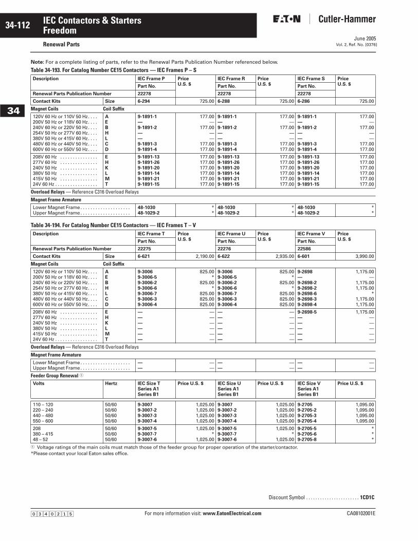
June 2005
34-112
For more information visit: www.EatonElectrical.com CA08102001E
IEC Contactors & Starters
34
FreedomRenewal Parts Vol. 2, Ref. No. [0376]
Note: For a complete listing of parts, refer to the Renewal Parts Publication Number referenced below.
Table 34-193. For Catalog Number CE15 Contactors — IEC Frames P – S
Table 34-194. For Catalog Number CE15 Contactors — IEC Frames T – V
� Voltage ratings of the main coils must match those of the feeder group for proper operation of the starter/contactor.*Please contact your local Eaton sales office.
Description IEC Frame P PriceU.S. $
IEC Frame R PriceU.S. $
IEC Frame S PriceU.S. $Part No. Part No. Part No.
Renewal Parts Publication Number 22278 22278 22278
Contact Kits Size 6-294 725.00 6-288 725.00 6-286 725.00
Magnet Coils Coil Suffix120V 60 Hz or 110V 50 Hz. . . . 200V 50 Hz or 118V 60 Hz. . . . 240V 60 Hz or 220V 50 Hz. . . . 254V 50 Hz or 277V 60 Hz. . . . 380V 50 Hz or 415V 60 Hz. . . . 480V 60 Hz or 440V 50 Hz. . . . 600V 60 Hz or 550V 50 Hz. . . .
AEBHLCD
9-1891-1—9-1891-2——9-1891-39-1891-4
177.00—
177.00——
177.00177.00
9-1891-1—9-1891-2——9-1891-39-1891-4
177.00—
177.00——
177.00177.00
9-1891-1—9-1891-2——9-1891-39-1891-4
177.00—
177.00——
177.00177.00
208V 60 Hz . . . . . . . . . . . . . . . 277V 60 Hz . . . . . . . . . . . . . . . 240V 50 Hz . . . . . . . . . . . . . . . 380V 50 Hz . . . . . . . . . . . . . . . 415V 50 Hz . . . . . . . . . . . . . . . 24V 60 Hz . . . . . . . . . . . . . . . . .
EHKLMT
9-1891-139-1891-269-1891-209-1891-149-1891-219-1891-15
177.00177.00177.00177.00177.00177.00
9-1891-139-1891-269-1891-209-1891-149-1891-219-1891-15
177.00177.00177.00177.00177.00177.00
9-1891-139-1891-269-1891-209-1891-149-1891-219-1891-15
177.00177.00177.00177.00177.00177.00
Overload Relays — Reference C316 Overload Relays Magnet Frame ArmatureLower Magnet Frame. . . . . . . . . . . . . . . . . . . . Upper Magnet Frame. . . . . . . . . . . . . . . . . . . .
48-103048-1029-2
**
48-103048-1029-2
**
48-103048-1029-2
**
Description IEC Frame T PriceU.S. $
IEC Frame U PriceU.S. $
IEC Frame V PriceU.S. $Part No. Part No. Part No.
Renewal Parts Publication Number 22275 22276 22586
Contact Kits Size 6-621 2,190.00 6-622 2,935.00 6-601 3,990.00
Magnet Coils Coil Suffix120V 60 Hz or 110V 50 Hz. . . . 200V 50 Hz or 118V 60 Hz. . . . 240V 60 Hz or 220V 50 Hz. . . . 254V 50 Hz or 277V 60 Hz. . . . 380V 50 Hz or 415V 60 Hz. . . . 480V 60 Hz or 440V 50 Hz. . . . 600V 60 Hz or 550V 50 Hz. . . .
AEBHLCD
9-30069-3006-59-3006-29-3006-69-3006-79-3006-39-3006-4
825.00*
825.00*
825.00825.00825.00
9-30069-3006-59-3006-29-3006-69-3006-79-3006-39-3006-4
825.00*
825.00*
825.00825.00825.00
9-2698—9-2698-29-2698-29-2698-69-2698-39-2698-4
1,175.00—
1,175.001,175.00
*1,175.001,175.00
208V 60 Hz . . . . . . . . . . . . . . . 277V 60 Hz . . . . . . . . . . . . . . . 240V 50 Hz . . . . . . . . . . . . . . . 380V 50 Hz . . . . . . . . . . . . . . . 415V 50 Hz . . . . . . . . . . . . . . . 24V 60 Hz . . . . . . . . . . . . . . . . .
EHKLMT
——————
——————
——————
——————
9-2698-5—————
1,175.00—————
Overload Relays — Reference C316 Overload Relays Magnet Frame ArmatureLower Magnet Frame. . . . . . . . . . . . . . . . . . . . Upper Magnet Frame. . . . . . . . . . . . . . . . . . . .
——
——
——
——
——
——
Feeder Group Renewal �
Volts Hertz IEC Size TSeries A1Series B1
Price U.S. $ IEC Size USeries A1Series B1
Price U.S. $ IEC Size VSeries A1Series B1
Price U.S. $
110 – 120220 – 240440 – 480550 – 600
50/6050/6050/6050/60
9-30079-3007-29-3007-39-3007-4
1,025.001,025.001,025.001,025.00
9-30079-3007-29-3007-39-3007-4
1,025.001,025.001,025.001,025.00
9-27059-2705-29-2705-39-2705-4
1,095.001,095.001,095.001,095.00
208380 – 41548 – 52
50/6050/6050/60
9-3007-59-3007-79-3007-6
1,025.00*
1,025.00
9-3007-59-3007-79-3007-6
1,025.00*
1,025.00
9-2705-59-2705-69-2705-8
***
Discount Symbol . . . . . . . . . . . . . . . . . . . . . . . 1CD1C
�������
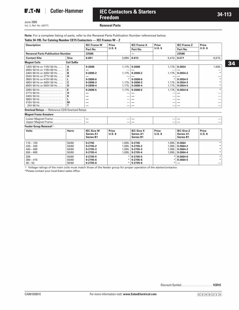
June 2005
CA08102001E For more information visit: www.EatonElectrical.com
34-113IEC Contactors & Starters
34
FreedomRenewal PartsVol. 2, Ref. No. [0377]
Note: For a complete listing of parts, refer to the Renewal Parts Publication Number referenced below.
Table 34-195. For Catalog Number CE15 Contactors — IEC Frames W – Z
� Voltage ratings of the main coils must match those of the feeder group for proper operation of the starter/contactor.*Please contact your local Eaton sales office.
Description IEC Frame W PriceU.S. $
IEC Frame X PriceU.S. $
IEC Frame Z PriceU.S. $Part No. Part No. Part No.
Renewal Parts Publication Number 22586 — 22586
Contact Kits Size 6-601 3,990. 6-613 5,410. 6-571 6,570.
Magnet Coils Coil Suffix120V 60 Hz or 110V 50 Hz . . . . 200V 50 Hz or 118V 60 Hz . . . . 240V 60 Hz or 220V 50 Hz . . . . 254V 50 Hz or 277V 60 Hz . . . . 380V 50 Hz or 415V 60 Hz . . . . 480V 60 Hz or 440V 50 Hz . . . . 600V 60 Hz or 550V 50 Hz . . . .
AEBHLCD
9-2698—9-2698-2—9-2698-69-2698-39-2698-4
1,175.—
1,175.—*
1,175.1,175.
9-2698—9-2698-2—9-2698-69-2698-39-2698-4
1,175.—
1,175.—*
1,175.1,175.
9-2654—9-2654-2—9-2654-59-2654-39-2654-4
1,935.—*
—***
208V 60 Hz . . . . . . . . . . . . . . . . 277V 60 Hz . . . . . . . . . . . . . . . . 240V 50 Hz . . . . . . . . . . . . . . . . 380V 50 Hz . . . . . . . . . . . . . . . . 415V 50 Hz . . . . . . . . . . . . . . . . 24V 60 Hz . . . . . . . . . . . . . . . .
EHKLMT
9-2698-5—————
1,175.—————
9-2698-5—————
1,175.—————
9-2654-6—————
*—————
Overload Relays — Reference C316 Overload RelaysMagnet Frame ArmatureLower Magnet Frame . . . . . . . . . . . . . . . . . . . . Upper Magnet Frame . . . . . . . . . . . . . . . . . . . .
——
——
——
——
——
——
Feeder Group Renewal�
Volts Hertz IEC Size WSeries A1Series B1
PriceU.S. $
IEC Size XSeries A1Series B1
Price U.S. $
IEC Size ZSeries A1Series B1
PriceU.S. $
110 – 120220 – 240440 – 480550 – 600
50/6050/6050/6050/60
9-27059-2705-29-2705-39-2705-4
1,095.1,095.1,095.1,095.
9-27059-2705-29-2705-39-2705-4
1,095.1,095.1,095.1,095.
9-26649-2664-29-2664-39-2664-4
****
208380 – 41548 – 52
50/6050/6050/60
9-2705-59-2705-69-2705-8
***
9-2705-59-2705-69-2705-8
***
9-2664-69-2664-5—
**
—
Discount Symbol . . . . . . . . . . . . . . . . . . . . . . . 1CD1C
�������
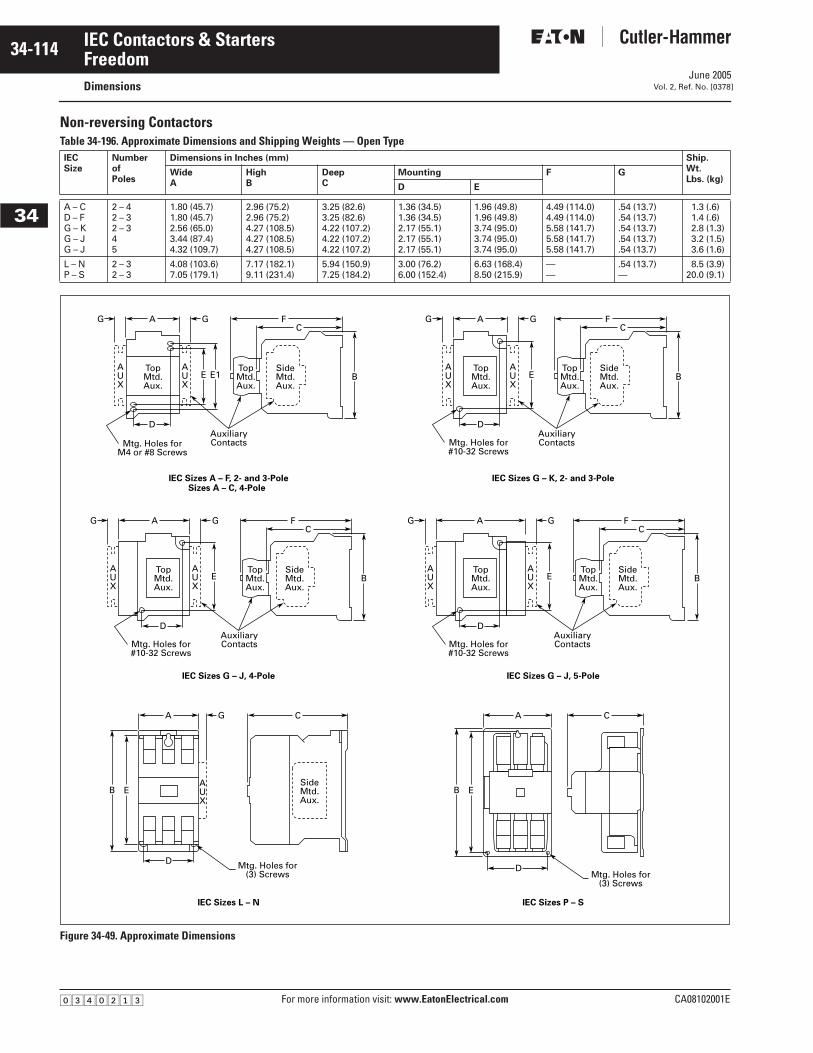
June 2005
34-114
For more information visit: www.EatonElectrical.com CA08102001E
IEC Contactors & Starters
34
FreedomDimensions Vol. 2, Ref. No. [0378]
Non-reversing ContactorsTable 34-196. Approximate Dimensions and Shipping Weights — Open Type
Figure 34-49. Approximate Dimensions
IECSize
NumberofPoles
Dimensions in Inches (mm) Ship.Wt.Lbs. (kg)
WideA
HighB
DeepC
Mounting F G
D E
A – CD – FG – KG – JG – J
2 – 42 – 32 – 345
1.80 (45.7)1.80 (45.7)2.56 (65.0)3.44 (87.4)4.32 (109.7)
2.96 (75.2)2.96 (75.2)4.27 (108.5)4.27 (108.5)4.27 (108.5)
3.25 (82.6)3.25 (82.6)4.22 (107.2)4.22 (107.2)4.22 (107.2)
1.36 (34.5)1.36 (34.5)2.17 (55.1)2.17 (55.1)2.17 (55.1)
1.96 (49.8)1.96 (49.8)3.74 (95.0)3.74 (95.0)3.74 (95.0)
4.49 (114.0)4.49 (114.0)5.58 (141.7)5.58 (141.7)5.58 (141.7)
.54 (13.7)
.54 (13.7)
.54 (13.7)
.54 (13.7)
.54 (13.7)
1.3 (.6)1.4 (.6)2.8 (1.3)3.2 (1.5)3.6 (1.6)
L – NP – S
2 – 32 – 3
4.08 (103.6)7.05 (179.1)
7.17 (182.1)9.11 (231.4)
5.94 (150.9)7.25 (184.2)
3.00 (76.2)6.00 (152.4)
6.63 (168.4)8.50 (215.9)
——
.54 (13.7)—
8.5 (3.9)20.0 (9.1)
A FC
BEAUX
AUX
E1
D
GG
TopMtd.Aux.
SideMtd.Aux.
TopMtd.Aux.
AuxiliaryContactsMtg. Holes for
M4 or #8 Screws
A FC
BEAUX
AUX
D
GG
TopMtd.Aux.
SideMtd.Aux.
TopMtd.Aux.
AuxiliaryContactsMtg. Holes for
#10-32 Screws
A FC
BE
EB
AUX
AUX
D
GG
A C
AUX
D
G
TopMtd.Aux.
SideMtd.Aux.
SideMtd.Aux.
TopMtd.Aux.
AuxiliaryContactsMtg. Holes for
#10-32 Screws
Mtg. Holes for(3) Screws
EB
A C
DMtg. Holes for
(3) Screws
IEC Sizes P – SIEC Sizes L – N
IEC Sizes G – J, 5-PoleIEC Sizes G – J, 4-Pole
IEC Sizes G – K, 2- and 3-PoleIEC Sizes A – F, 2- and 3-PoleSizes A – C, 4-Pole
A FC
BEAUX
AUX
D
GG
TopMtd.Aux.
SideMtd.Aux.
TopMtd.Aux.
AuxiliaryContactsMtg. Holes for
#10-32 Screws
�������
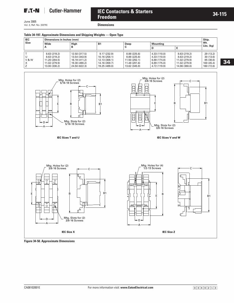
June 2005
CA08102001E For more information visit: www.EatonElectrical.com
34-115IEC Contactors & Starters
34
FreedomDimensions Vol. 2, Ref. No. [0379]
Table 34-197. Approximate Dimensions and Shipping Weights — Open Type
Figure 34-50. Approximate Dimensions
IECSize
Dimensions in Inches (mm) Ship.Wt.Lbs. (kg)
WideA
HighB
B1 DeepC
Mounting
D E
TUV & WXZ
8.63 (219.2)8.63 (219.2)
11.20 (284.5)11.02 (279.9)13.00 (330.2)
12.50 (317.5)13.54 (343.9)16.19 (411.2)19.30 (490.2)24.50 (622.3)
9.17 (232.9)10.16 (258.1)12.13 (308.1)14.16 (359.7)19.25 (489.0)
8.88 (225.6)8.88 (225.6)
11.50 (292.1)11.48 (291.6)13.62 (345.9)
4.33 (110.0)4.33 (110.0)6.88 (174.8)6.89 (175.0)4.72 (119.9)
8.63 (219.2)8.63 (219.2)
11.02 (279.9)11.02 (279.9)14.96 (380.0)
29 (13.2)30 (13.6)85 (38.6)
100 (45.4)160 (72.6)
B
C
D
A
Mtg. Slots for (2)5/16-18 Screws
Mtg. Holes for (2)5/16-18 Screws
E B1 B
C
D
A
Mtg. Slots for (2)3/8-16 Screws
Mtg. Holes for (2)3/8-16 Screws
E B1
BE
C C
D
AD
A
IEC Size ZIEC Size X
IEC Sizes V and WIEC Sizes T and U
Mtg. Slots for (2)3/8-16 Screws
Mtg. Holes for (2)3/8-16 Screws
Mtg. Holes for (4)1/2-13 Screws
B1E B1
B
�������
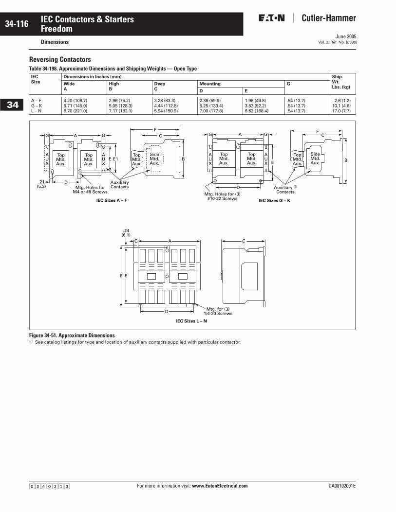
June 2005
34-116
For more information visit: www.EatonElectrical.com CA08102001E
IEC Contactors & Starters
34
FreedomDimensions Vol. 2, Ref. No. [0380]
Reversing ContactorsTable 34-198. Approximate Dimensions and Shipping Weights — Open Type
Figure 34-51. Approximate Dimensions� See catalog listings for type and location of auxiliary contacts supplied with particular contactor.
IECSize
Dimensions in Inches (mm) Ship.Wt.Lbs. (kg)
WideA
HighB
DeepC
Mounting G
D E
A – FG – KL – N
4.20 (106.7)5.71 (145.0)8.70 (221.0)
2.96 (75.2)5.05 (128.3)7.17 (182.1)
3.28 (83.3)4.44 (112.8)5.94 (150.9)
2.36 (59.9)5.25 (133.4)7.00 (177.8)
1.96 (49.8)3.63 (92.2)6.63 (168.4)
.54 (13.7)
.54 (13.7)
.54 (13.7)
2.6 (1.2)10.1 (4.6)17.0 (7.7)
GG A
D
E E1 B
.24(6.1)
AF
C
C
BE
IEC Sizes L – N
IEC Sizes G – K
FC
AUX
AUX
TopMtd.Aux.
TopMtd.Aux.
SideMtd.Aux.
TopMtd.Aux.
AuxiliaryContacts
.21(5.3) Mtg. Holes for
M4 or #8 Screws
IEC Sizes A – F
AUX
AUX
D
GG
AG
B E
D
TopMtd.Aux.
TopMtd.Aux.
TopMtd.Aux.
SideMtd.Aux.
Auxiliary �ContactsMtg. Holes for (3)
#10-32 Screws
Mtg. for (3)1/4-20 Screws
�������

June 2005
CA08102001E For more information visit: www.EatonElectrical.com
34-117IEC Contactors & Starters
34
FreedomDimensions Vol. 2, Ref. No. [0381]
Non-reversing Fixed Heater Starters Table 34-199. Approximate Dimensions and Shipping Weights — Open Type
Figure 34-52. Approximate Dimensions
IECSize
Dimensions in Inches (mm) Ship.Wt.Lbs. (kg)
WideA
High DeepC
Mounting F G
B B1 D D1 E E1
A – FG – KL – NP – S
1.80 (45.7)2.56 (65.0)4.36 (110.7)7.37 (187.2)
5.32 (135.1)7.12 (180.8)
12.12 (307.8)16.01 (406.7)
1.50 (38.1)———
3.66 (93.0)4.65 (118.1)5.89 (149.6)7.31 (185.7)
1.36 (34.5)2.00 (50.8)1.77 (45.0)3.00 (76.2)
——3.00 (76.2)6.00 (152.4)
1.96 (49.8)6.63 (168.4)
10.81 (274.6)8.50 (215.9)
2.36 (59.9)3.54 (89.9)——
4.66 (118.4)5.83 (148.1).55 (14)
—
.54 (13.7)
.54 (13.7)——
1.8 (.8)4.0 (1.8)
12.0 (5.4)36.0 (16.3)
D
Non-reversing Starter AE17IEC Series P – S
B
E
A CD1
Mtg. Holes for (3)1/4-20 ScrewsD C
AD1
F
Non-reversing Starter AE17IEC Series L – N
B E
Mtg. Holes for (3)1/4-20 Screws
SideMtd.Aux.
A F
B
B1
AUX
C
IEC StartersSizes A – F
DG
TopMtd.Aux.
SideMtd.Aux.
TopMtd.Aux.
OptionalAuxiliaryContacts
For#8 or M4
Mtg.Screws
Size FTerminal
Block
E E1
F
CD
IEC StartersSizes G – K
A G
AUX
TopMtd.Aux.
SideMtd.Aux.
TopMtd.Aux.
OptionalAuxiliaryContacts
.13(3.3)
EB
3 Mtg. Holesfor M5 or
#10-32 Screws
�������
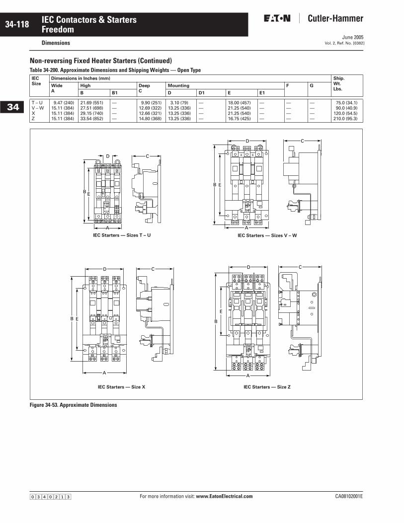
June 2005
34-118
For more information visit: www.EatonElectrical.com CA08102001E
IEC Contactors & Starters
34
FreedomDimensions Vol. 2, Ref. No. [0382]
Non-reversing Fixed Heater Starters (Continued)Table 34-200. Approximate Dimensions and Shipping Weights — Open Type
Figure 34-53. Approximate Dimensions
IECSize
Dimensions in Inches (mm) Ship.Wt.Lbs.
WideA
High DeepC
Mounting F G
B B1 D D1 E E1
T – UV – WXZ
9.47 (240)15.11 (384)15.11 (384)15.11 (384)
21.69 (551)27.51 (698)29.15 (740)33.54 (852)
————
9.90 (251)12.69 (322)12.66 (321)14.80 (368)
3.10 (79)13.25 (336)13.25 (336)13.25 (336)
————
18.00 (457)21.25 (540)21.25 (540)16.75 (425)
————
————
————
75.0 (34.1)90.0 (40.9)
120.0 (54.5)210.0 (95.3)
CD
EB
A
IEC Starters — Sizes T – U
CD
EB
A
IEC Starters — Sizes V – W
C
EB
E
B
A
CD
A
D
IEC Starters — Size X IEC Starters — Size Z
�������
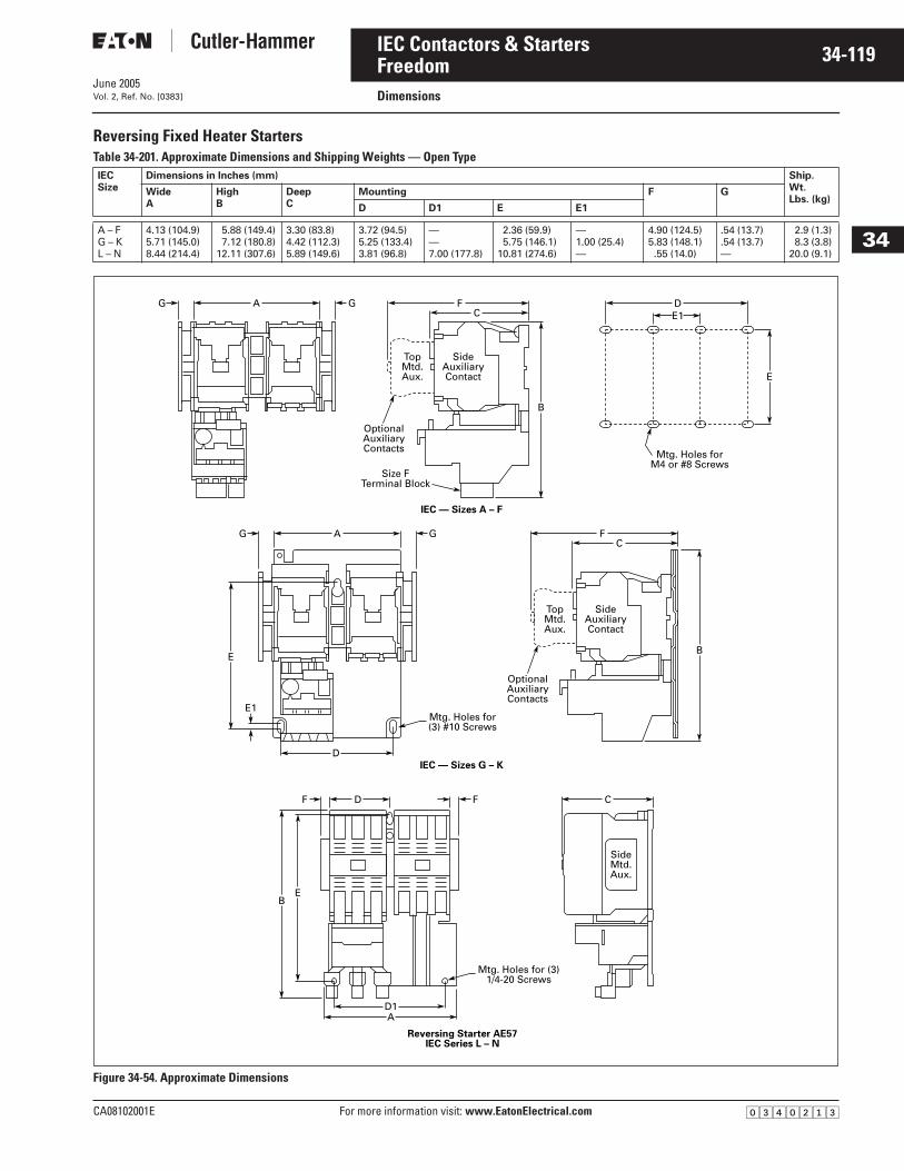
June 2005
CA08102001E For more information visit: www.EatonElectrical.com
34-119IEC Contactors & Starters
34
FreedomDimensions Vol. 2, Ref. No. [0383]
Reversing Fixed Heater Starters Table 34-201. Approximate Dimensions and Shipping Weights — Open Type
Figure 34-54. Approximate Dimensions
IECSize
Dimensions in Inches (mm) Ship.Wt.Lbs. (kg)
WideA
HighB
DeepC
Mounting F G
D D1 E E1
A – FG – KL – N
4.13 (104.9)5.71 (145.0)8.44 (214.4)
5.88 (149.4)7.12 (180.8)
12.11 (307.6)
3.30 (83.8)4.42 (112.3)5.89 (149.6)
3.72 (94.5)5.25 (133.4)3.81 (96.8)
——7.00 (177.8)
2.36 (59.9)5.75 (146.1)
10.81 (274.6)
—1.00 (25.4)—
4.90 (124.5)5.83 (148.1).55 (14.0)
.54 (13.7)
.54 (13.7)—
2.9 (1.3)8.3 (3.8)
20.0 (9.1)
D CFF
BE
SideMtd.Aux.
Reversing Starter AE57IEC Series L – N
Mtg. Holes for (3)1/4-20 Screws
AD1
A F DC
FC
E1
B
GG
A GG
E
E
E1
B
SideAuxiliaryContact
TopMtd.Aux.
SideAuxiliaryContact
TopMtd.Aux.
OptionalAuxiliaryContacts
OptionalAuxiliaryContacts
Mtg. Holes forM4 or #8 Screws
Mtg. Holes for(3) #10 Screws
IEC — Sizes A – F
IEC — Sizes G – K
Size FTerminal Block
D
�������
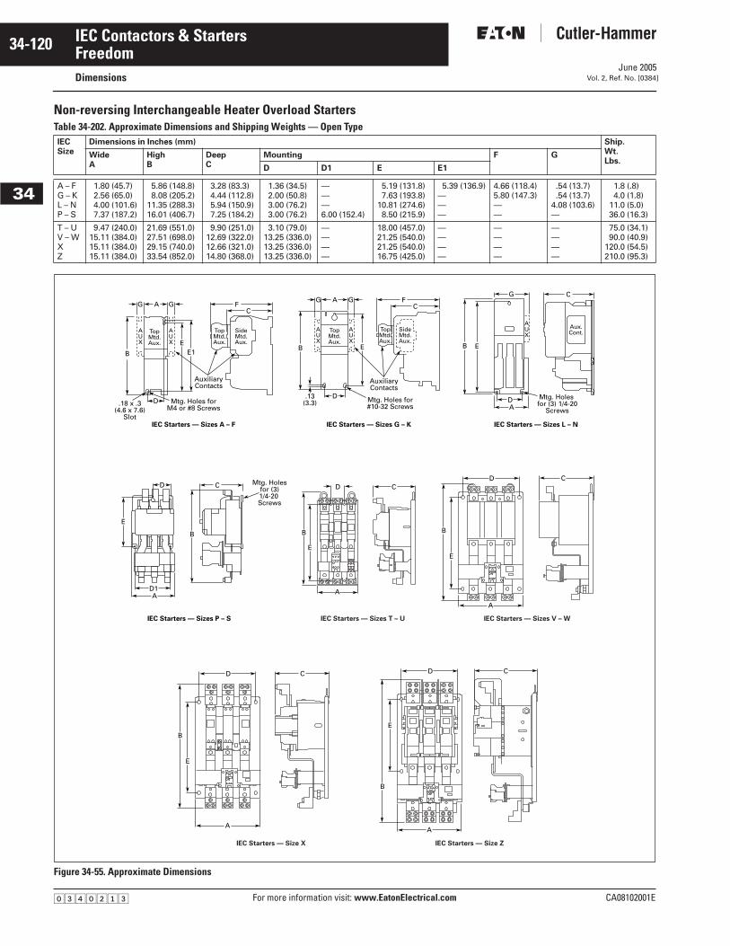
June 2005
34-120
For more information visit: www.EatonElectrical.com CA08102001E
IEC Contactors & Starters
34
FreedomDimensions Vol. 2, Ref. No. [0384]
Non-reversing Interchangeable Heater Overload Starters Table 34-202. Approximate Dimensions and Shipping Weights — Open Type
Figure 34-55. Approximate Dimensions
IECSize
Dimensions in Inches (mm) Ship.Wt.Lbs.
WideA
HighB
DeepC
Mounting F G
D D1 E E1
A – FG – KL – NP – S
1.80 (45.7)2.56 (65.0)4.00 (101.6)7.37 (187.2)
5.86 (148.8)8.08 (205.2)
11.35 (288.3)16.01 (406.7)
3.28 (83.3)4.44 (112.8)5.94 (150.9)7.25 (184.2)
1.36 (34.5)2.00 (50.8)3.00 (76.2)3.00 (76.2)
———6.00 (152.4)
5.19 (131.8)7.63 (193.8)
10.81 (274.6)8.50 (215.9)
5.39 (136.9)———
4.66 (118.4)5.80 (147.3)——
.54 (13.7)
.54 (13.7)4.08 (103.6)—
1.8 (.8)4.0 (1.8)
11.0 (5.0)36.0 (16.3)
T – UV – WXZ
9.47 (240.0)15.11 (384.0)15.11 (384.0)15.11 (384.0)
21.69 (551.0)27.51 (698.0)29.15 (740.0)33.54 (852.0)
9.90 (251.0)12.69 (322.0)12.66 (321.0)14.80 (368.0)
3.10 (79.0)13.25 (336.0)13.25 (336.0)13.25 (336.0)
————
18.00 (457.0)21.25 (540.0)21.25 (540.0)16.75 (425.0)
————
————
————
75.0 (34.1)90.0 (40.9)
120.0 (54.5)210.0 (95.3)
IEC Starters — Sizes L – NIEC Starters — Sizes A – F IEC Starters — Sizes G – K
B
.13(3.3)
D
A FC
GG
E
AUX
AUX
TopMtd.Aux.
SideMtd.Aux.
TopMtd.Aux.
AuxiliaryContacts
Mtg. Holes for#10-32 Screws A
D
B E
G C
AUX
Aux.Cont.
Mtg. Holes for (3) 1/4-20
Screws
B
A FC
E
AUX
AUX
E1
D
GG
TopMtd.Aux.
SideMtd.Aux.
TopMtd.Aux.
AuxiliaryContacts
.18 x .3(4.6 x 7.6)
Slot
Mtg. Holes forM4 or #8 Screws
IEC Starters — Sizes P – S
AD1
E
B
D C Mtg. Holesfor (3)1/4-20 Screws
CD
E
B
A
IEC Starters — Sizes T – U
CD
E
B
A
IEC Starters — Sizes V – W
C
E
B
A
D
IEC Starters — Size X
E
B
A
CD
IEC Starters — Size Z
�������
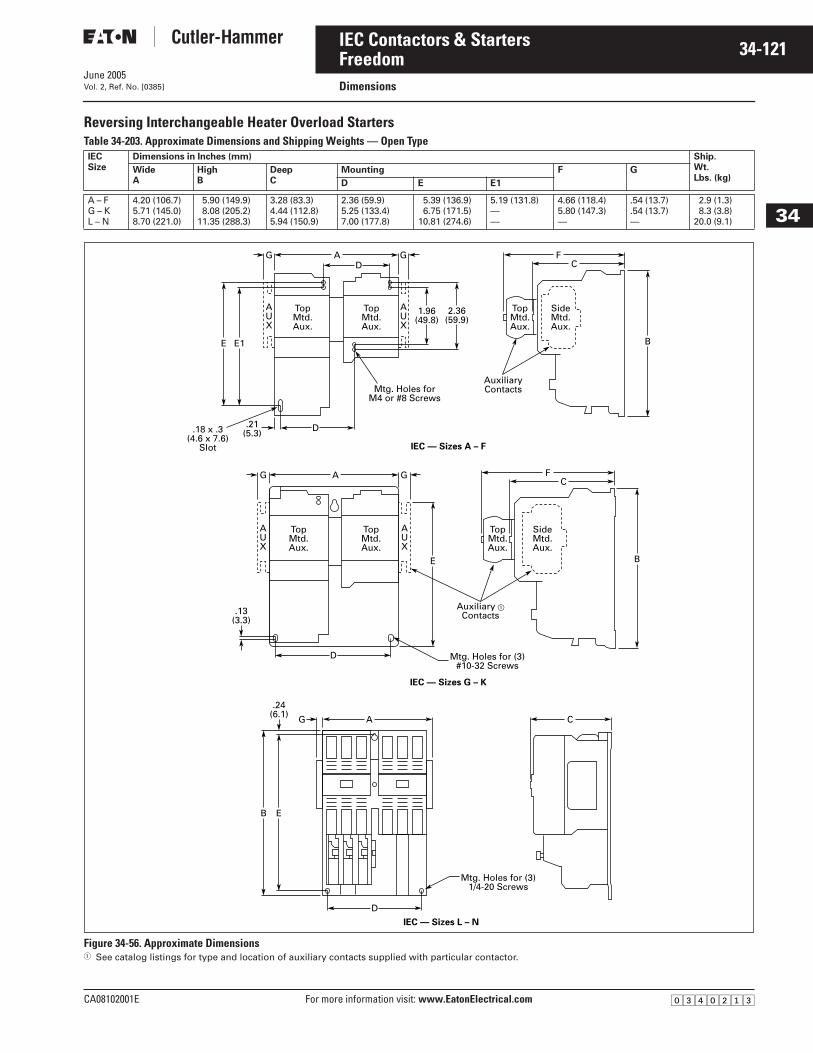
June 2005
CA08102001E For more information visit: www.EatonElectrical.com
34-121IEC Contactors & Starters
34
FreedomDimensions Vol. 2, Ref. No. [0385]
Reversing Interchangeable Heater Overload Starters Table 34-203. Approximate Dimensions and Shipping Weights — Open Type
Figure 34-56. Approximate Dimensions� See catalog listings for type and location of auxiliary contacts supplied with particular contactor.
IECSize
Dimensions in Inches (mm) Ship.Wt.Lbs. (kg)
WideA
HighB
DeepC
Mounting F G
D E E1
A – FG – KL – N
4.20 (106.7)5.71 (145.0)8.70 (221.0)
5.90 (149.9)8.08 (205.2)
11.35 (288.3)
3.28 (83.3)4.44 (112.8)5.94 (150.9)
2.36 (59.9)5.25 (133.4)7.00 (177.8)
5.39 (136.9)6.75 (171.5)
10.81 (274.6)
5.19 (131.8)——
4.66 (118.4)5.80 (147.3)—
.54 (13.7)
.54 (13.7)—
2.9 (1.3)8.3 (3.8)
20.0 (9.1)
A FC
B
1.96(49.8)
2.36(59.9)
.21(5.3)
.13(3.3)
AUX
AUX
D
D
IEC — Sizes A – F
IEC — Sizes G – K
IEC — Sizes L – N
D
DGG
.24(6.1)
A GG F
AG C
C
BE
E
B E
E1
TopMtd.Aux.
TopMtd.Aux.
AUX
AUX
TopMtd.Aux.
TopMtd.Aux.
SideMtd.Aux.
TopMtd.Aux.
SideMtd.Aux.
TopMtd.Aux.
AuxiliaryContacts
Auxiliary �Contacts
Mtg. Holes forM4 or #8 Screws
Mtg. Holes for (3)#10-32 Screws
Mtg. Holes for (3)1/4-20 Screws
.18 x .3(4.6 x 7.6)
Slot
�������
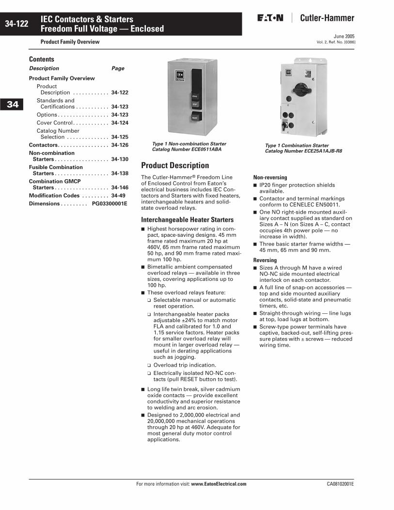
June 2005
34-122
For more information visit: www.EatonElectrical.com CA08102001E
IEC Contactors & Starters
34
Freedom Full Voltage — EnclosedProduct Family Overview Vol. 2, Ref. No. [0386]
Contents Description Page
Product Family Overview
Product Description . . . . . . . . . . . . 34-122
Standards and Certifications . . . . . . . . . . . 34-123
Options . . . . . . . . . . . . . . . . . 34-123
Cover Control. . . . . . . . . . . . 34-124
Catalog Number Selection . . . . . . . . . . . . . . 34-125
Contactors. . . . . . . . . . . . . . . . . 34-126
Non-combination Starters . . . . . . . . . . . . . . . . . . 34-130
Fusible CombinationStarters . . . . . . . . . . . . . . . . . . 34-138
Combination GMCPStarters . . . . . . . . . . . . . . . . . . 34-146
Modification Codes . . . . . . . . . 34-49
Dimensions . . . . . . . . . PG03300001E
Type 1 Non-combination StarterCatalog Number ECE0511ABA
Type 1 Combination StarterCatalog Number ECE25A1AJB-R8
Product DescriptionThe Cutler-Hammer® Freedom Line of Enclosed Control from Eaton’s electrical business includes IEC Con-tactors and Starters with fixed heaters, interchangeable heaters and solid-state overload relays.
Interchangeable Heater Starters■ Highest horsepower rating in com-
pact, space-saving designs. 45 mm frame rated maximum 20 hp at 460V, 65 mm frame rated maximum 50 hp, and 90 mm frame rated maxi-mum 100 hp.
■ Bimetallic ambient compensated overload relays — available in three sizes, covering applications up to 100 hp.
■ These overload relays feature:❑ Selectable manual or automatic
reset operation.❑ Interchangeable heater packs
adjustable ±24% to match motor FLA and calibrated for 1.0 and 1.15 service factors. Heater packs for smaller overload relay will mount in larger overload relay — useful in derating applications such as jogging.
❑ Overload trip indication.❑ Electrically isolated NO-NC con-
tacts (pull RESET button to test).
■ Long life twin break, silver cadmium oxide contacts — provide excellent conductivity and superior resistance to welding and arc erosion.
■ Designed to 2,000,000 electrical and 20,000,000 mechanical operations through 20 hp at 460V. Adequate for most general duty motor control applications.
Non-reversing■ IP20 finger protection shields
available.■ Contactor and terminal markings
conform to CENELEC EN50011.■ One NO right-side mounted auxil-
iary contact supplied as standard on Sizes A – N (on Sizes A – C, contact occupies 4th power pole — no increase in width).
■ Three basic starter frame widths — 45 mm, 65 mm and 90 mm.
Reversing■ Sizes A through M have a wired
NO-NC side mounted electrical interlock on each contactor.
■ A full line of snap-on accessories — top and side mounted auxiliary contacts, solid-state and pneumatic timers, etc.
■ Straight-through wiring — line lugs at top, load lugs at bottom.
■ Screw-type power terminals have captive, backed-out, self-lifting pres-sure plates with ± screws — reduced wiring time.
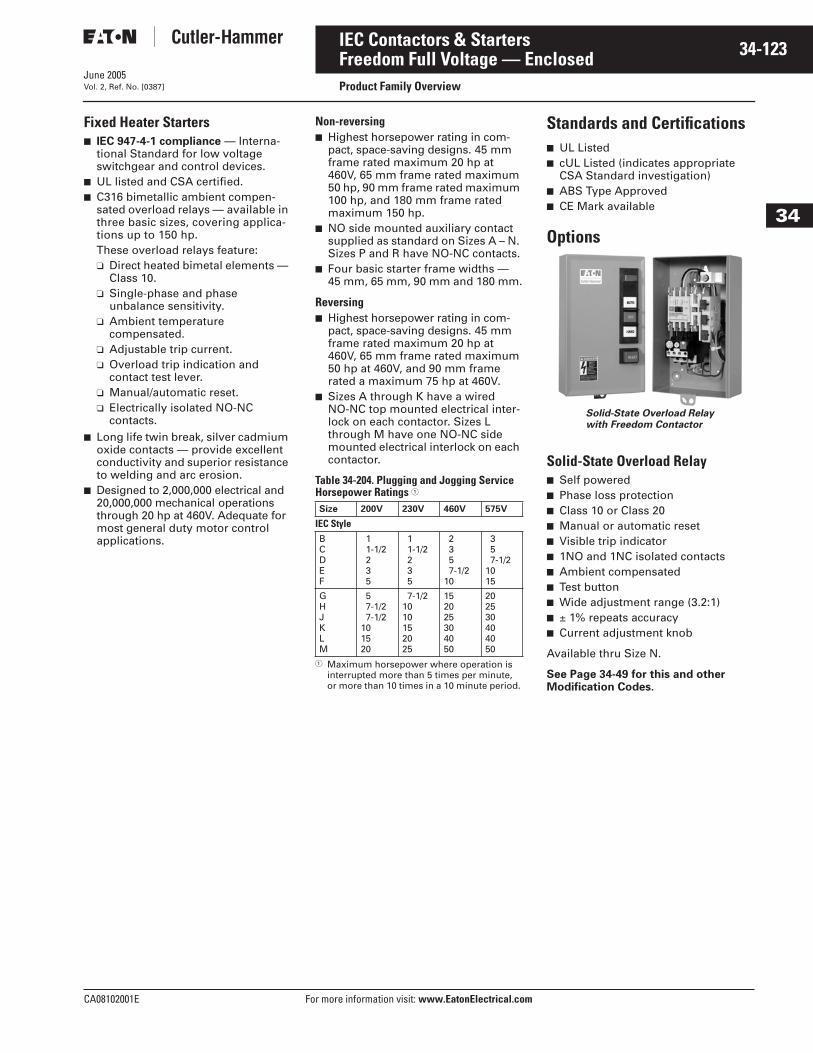
June 2005
CA08102001E For more information visit: www.EatonElectrical.com
34-123IEC Contactors & Starters
34
Freedom Full Voltage — EnclosedProduct Family OverviewVol. 2, Ref. No. [0387]
Fixed Heater Starters■ IEC 947-4-1 compliance — Interna-
tional Standard for low voltage switchgear and control devices.
■ UL listed and CSA certified.■ C316 bimetallic ambient compen-
sated overload relays — available in three basic sizes, covering applica-tions up to 150 hp.These overload relays feature:❑ Direct heated bimetal elements —
Class 10.❑ Single-phase and phase
unbalance sensitivity.❑ Ambient temperature
compensated.❑ Adjustable trip current.❑ Overload trip indication and
contact test lever.❑ Manual/automatic reset.❑ Electrically isolated NO-NC
contacts.■ Long life twin break, silver cadmium
oxide contacts — provide excellent conductivity and superior resistance to welding and arc erosion.
■ Designed to 2,000,000 electrical and 20,000,000 mechanical operations through 20 hp at 460V. Adequate for most general duty motor control applications.
Non-reversing■ Highest horsepower rating in com-
pact, space-saving designs. 45 mm frame rated maximum 20 hp at 460V, 65 mm frame rated maximum 50 hp, 90 mm frame rated maximum 100 hp, and 180 mm frame rated maximum 150 hp.
■ NO side mounted auxiliary contact supplied as standard on Sizes A – N. Sizes P and R have NO-NC contacts.
■ Four basic starter frame widths — 45 mm, 65 mm, 90 mm and 180 mm.
Reversing■ Highest horsepower rating in com-
pact, space-saving designs. 45 mm frame rated maximum 20 hp at 460V, 65 mm frame rated maximum 50 hp at 460V, and 90 mm frame rated a maximum 75 hp at 460V.
■ Sizes A through K have a wired NO-NC top mounted electrical inter-lock on each contactor. Sizes L through M have one NO-NC side mounted electrical interlock on each contactor.
Table 34-204. Plugging and Jogging Service Horsepower Ratings �
� Maximum horsepower where operation is interrupted more than 5 times per minute, or more than 10 times in a 10 minute period.
Standards and Certifications■ UL Listed■ cUL Listed (indicates appropriate
CSA Standard investigation)■ ABS Type Approved■ CE Mark available
Options
Solid-State Overload Relay■ Self powered■ Phase loss protection■ Class 10 or Class 20■ Manual or automatic reset■ Visible trip indicator■ 1NO and 1NC isolated contacts■ Ambient compensated■ Test button■ Wide adjustment range (3.2:1)■ ± 1% repeats accuracy■ Current adjustment knob
Available thru Size N.
See Page 34-49 for this and other Modification Codes.
Size 200V 230V 460V 575V
IEC StyleBCDEF
11-1/2235
11-1/2235
2357-1/2
10
357-1/2
1015
GHJKLM
57-1/27-1/2
101520
7-1/21010152025
152025304050
202530404050
Solid-State Overload Relay with Freedom Contactor
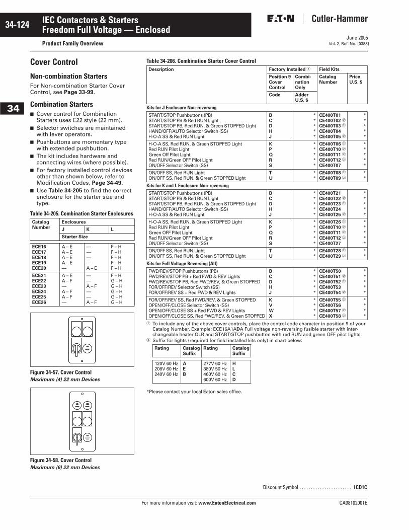
June 2005
34-124
For more information visit: www.EatonElectrical.com CA08102001E
IEC Contactors & Starters
34
Freedom Full Voltage — EnclosedProduct Family Overview Vol. 2, Ref. No. [0388]
Cover Control
Non-combination StartersFor Non-combination Starter Cover Control, see Page 33-99.
Combination Starters■ Cover control for Combination
Starters uses E22 style (22 mm).■ Selector switches are maintained
with lever operators.■ Pushbuttons are momentary type
with extended pushbutton.■ The kit includes hardware and
connecting wires (where possible).■ For factory installed control devices
other than shown below, refer to Modification Codes, Page 34-49.
■ Use Table 34-205 to find the correct enclosure for the starter size and type.
Table 34-205. Combination Starter Enclosures
Figure 34-57. Cover Control Maximum (4) 22 mm Devices
Figure 34-58. Cover ControlMaximum (6) 22 mm Devices
CatalogNumber
Enclosures
J K L
Starter Size
ECE16ECE17ECE18ECE19ECE20
A – EA – EA – EA – E—
————A – E
F – HF – HF – HF – HF – H
ECE21ECE22ECE23ECE24ECE25ECE26
A – EA – F—A – FA – F—
——A – F——A – F
F – HG – HG – HG – HG – HG – H
Table 34-206. Combination Starter Cover Control
� To include any of the above cover controls, place the control code character in position 9 of your Catalog Number. Example: ECE16A1ADA Full voltage non-reversing fusible starter with inter-changeable heater OLR and START/STOP pushbutton with red RUN and green OFF pilot lights.
� Suffix for lights (required for field installed kits only) in chart below:
*Please contact your local Eaton sales office.
Description Factory Installed � Field Kits
Position 9CoverControl
Combi-nationOnly
CatalogNumber
PriceU.S. $
Code Adder U.S. $
Kits for J Enclosure Non-reversingSTART/STOP Pushbuttons (PB)START/STOP PB & Red RUN LightSTART/STOP PB, Red RUN, & Green STOPPED LightHAND/OFF/AUTO Selector Switch (SS)H-O-A SS & Red RUN Light
BCDHJ
*****
CE400T01CE400T02 �
CE400T03 �
CE400T04CE400T05 �
*****
H-O-A SS, Red RUN, & Green STOPPED LightRed RUN Pilot LightGreen Off Pilot LightRed RUN/Green OFF Pilot LightON/OFF Selector Switch (SS)
KPQRS
*****
CE400T06 �
CE400T10 �
CE400T11 �
CE400T12 �
CE400T07
*****
ON/OFF SS, Red RUN LightON/OFF SS, Red RUN, & Green STOPPED Light
TU
**
CE400T08 �
CE400T09 �**
Kits for K and L Enclosure Non-reversingSTART/STOP Pushbuttons (PB)START/STOP PB & Red RUN LightSTART/STOP PB, Red RUN, & Green STOPPED LightHAND/OFF/AUTO Selector Switch (SS)H-O-A SS & Red RUN Light
BCDHJ
*****
CE400T21CE400T22 �
CE400T23 �
CE400T24CE400T25 �
*****
H-O-A SS, Red RUN, & Green STOPPED LightRed RUN Pilot LightGreen OFF Pilot LightRed RUN/Green OFF Pilot LightON/OFF Selector Switch (SS)
KPQRS
*****
CE400T26 �
CE400T10 �
CE400T11 �
CE400T12 �
CE400T27
*****
ON/OFF SS, Red RUN LightON/OFF SS, Red RUN, & Green STOPPED Light
TU
**
CE400T28 �
CE400T29 �**
Kits for Full Voltage Reversing (All)FWD/REV/STOP Pushbuttons (PB)FWD/REV/STOP PB + Red FWD & REV LightsFWD/REV/STOP PB, Red FWD/REV, & Green STOPPEDFOR/OFF/REV Selector Switch (SS)FOR/OFF/REV SS + Red FWD & REV Lights
BCDHJ
*****
CE400T50CE400T51 �
CE400T52 �
CE400T53CE400T54 �
*****
FOR/OFF/REV SS, Red FWD/REV, & Green STOPPEDOPEN/OFF/CLOSE Selector Switch (SS)OPEN/OFF/CLOSE SS + Red FWD & REV LightsOPEN/OFF/CLOSE SS, Red FWD/REV, & Green STOPPED
KVWX
****
CE400T55 �
CE400T56CE400T57 �
CE400T58 �
****
Rating CatalogSuffix
Rating CatalogSuffix
120V 60 Hz208V 60 Hz240V 60 Hz
AEB
277V 60 Hz380V 50 Hz460V 60 Hz600V 60 Hz
HLCD
Discount Symbol . . . . . . . . . . . . . . . . . . . . . . . 1CD1C
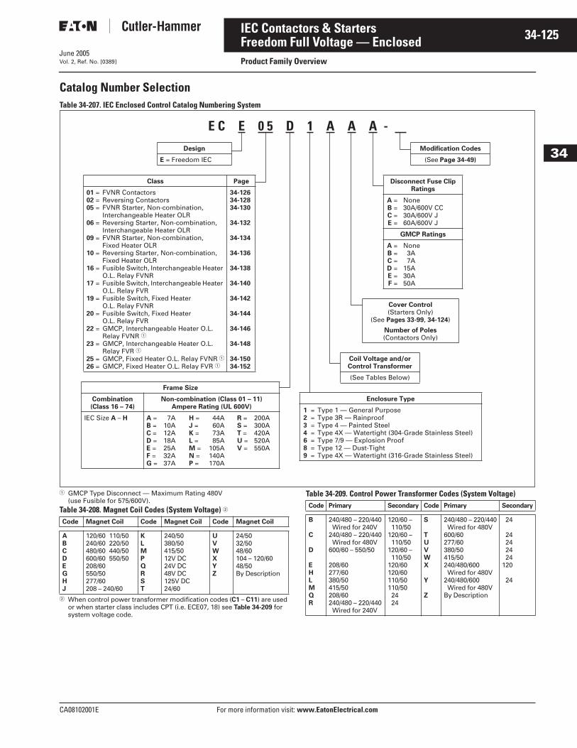
June 2005
CA08102001E For more information visit: www.EatonElectrical.com
34-125IEC Contactors & Starters
34
Freedom Full Voltage — EnclosedProduct Family OverviewVol. 2, Ref. No. [0389]
Catalog Number Selection Table 34-207. IEC Enclosed Control Catalog Numbering System
� GMCP Type Disconnect — Maximum Rating 480V (use Fusible for 575/600V).
Table 34-208. Magnet Coil Codes (System Voltage) �
� When control power transformer modification codes (C1 – C11) are used or when starter class includes CPT (i.e. ECE07, 18) see Table 34-209 for system voltage code.
Table 34-209. Control Power Transformer Codes (System Voltage)
E C E 0 5 D 1 A A A -
Modification Codes
(See Page 34-49)
Disconnect Fuse Clip Ratings
A =B =C =E =
None30A/600V CC30A/600V J60A/600V J
GMCP Ratings
A =B =C =D =E =F =
None3A7A
15A30A50A
Class Page
01 =02 =05 =
06 =
09 =
10 =
16 =
17 =
19 =
20 =
22 =
23 =
25 =26 =
FVNR ContactorsReversing ContactorsFVNR Starter, Non-combination, Interchangeable Heater OLRReversing Starter, Non-combination, Interchangeable Heater OLRFVNR Starter, Non-combination, Fixed Heater OLRReversing Starter, Non-combination, Fixed Heater OLRFusible Switch, Interchangeable Heater O.L. Relay FVNRFusible Switch, Interchangeable Heater O.L. Relay FVRFusible Switch, Fixed HeaterO.L. Relay FVNRFusible Switch, Fixed HeaterO.L. Relay FVRGMCP, Interchangeable Heater O.L.Relay FVNR �GMCP, Interchangeable Heater O.L.Relay FVR �GMCP, Fixed Heater O.L. Relay FVNR �GMCP, Fixed Heater O.L. Relay FVR �
34-12634-12834-130
34-132
34-134
34-136
34-138
34-140
34-142
34-144
34-146
34-148
34-15034-152
Cover Control(Starters Only)
(See Pages 33-99, 34-124)
Number of Poles(Contactors Only)
Design
E = Freedom IEC
Frame Size
Combination(Class 16 – 74)
Non-combination (Class 01 – 11)Ampere Rating (UL 600V)
IEC Size A – H A =B =C =D =E =F =G =
7A10A12A18A25A32A37A
H =J =K =L =M =N =P =
44A60A73A85A
105A140A170A
R =S =T =U =V =
200A300A420A520A550A
Coil Voltage and/or Control Transformer
(See Tables Below)
Enclosure Type
1 =2 =3 =4 =6 =8 =9 =
Type 1 — General PurposeType 3R — RainproofType 4 — Painted SteelType 4X — Watertight (304-Grade Stainless Steel)Type 7/9 — Explosion ProofType 12 — Dust-TightType 4X — Watertight (316-Grade Stainless Steel)
Code Magnet Coil Code Magnet Coil Code Magnet Coil
ABCDEGHJ
120/60 110/50240/60 220/50480/60 440/50600/60 550/50208/60550/50277/60208 – 240/60
KLMPQRST
240/50380/50415/5012V DC24V DC48V DC125V DC24/60
UVWXYZ
24/5032/5048/60104 – 120/6048/50By Description
Code Primary Secondary Code Primary Secondary
B
C
D
EHLMQR
240/480 – 220/440Wired for 240V
240/480 – 220/440Wired for 480V
600/60 – 550/50
208/60277/60380/50415/50208/60240/480 – 220/440Wired for 240V
120/60 – 110/50
120/60 – 110/50
120/60 – 110/50
120/60120/60110/50110/502424
S
TUVWX
Y
Z
240/480 – 220/440Wired for 480V
600/60277/60380/50415/50240/480/600Wired for 480V
240/480/600Wired for 480V
By Description
24
24242424
120
24
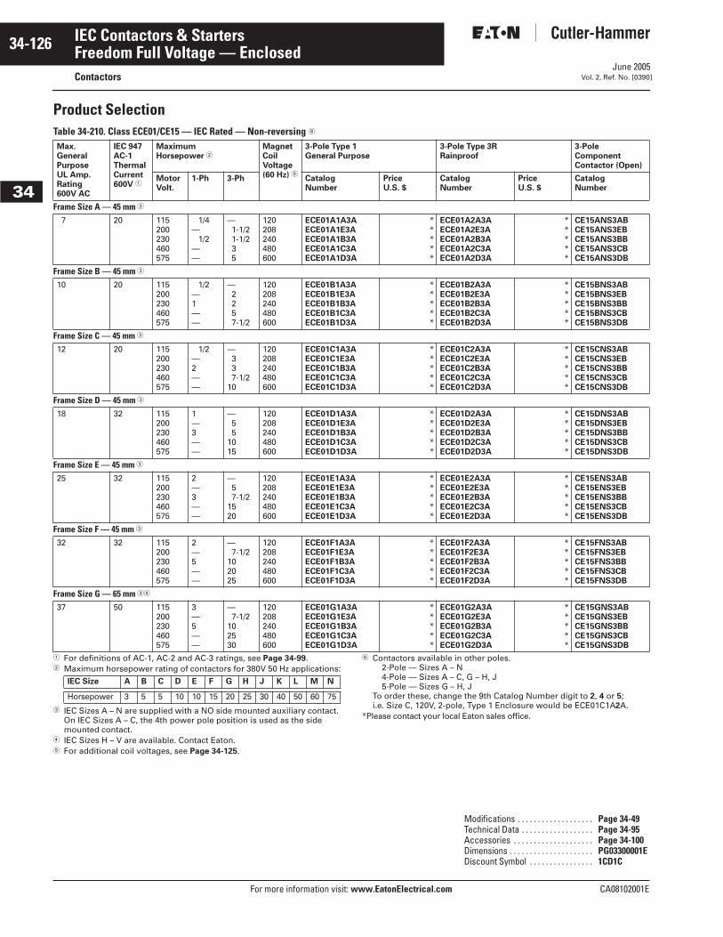
June 2005
34-126
For more information visit: www.EatonElectrical.com CA08102001E
IEC Contactors & Starters
34
Freedom Full Voltage — EnclosedContactors Vol. 2, Ref. No. [0390]
Product SelectionTable 34-210. Class ECE01/CE15 — IEC Rated — Non-reversing �
� For definitions of AC-1, AC-2 and AC-3 ratings, see Page 34-99.� Maximum horsepower rating of contactors for 380V 50 Hz applications:
� IEC Sizes A – N are supplied with a NO side mounted auxiliary contact. On IEC Sizes A – C, the 4th power pole position is used as the side mounted contact.
� IEC Sizes H – V are available. Contact Eaton.� For additional coil voltages, see Page 34-125.
� Contactors available in other poles.2-Pole — Sizes A – N4-Pole — Sizes A – C, G – H, J5-Pole — Sizes G – H, J
To order these, change the 9th Catalog Number digit to 2, 4 or 5; i.e. Size C, 120V, 2-pole, Type 1 Enclosure would be ECE01C1A2A.
*Please contact your local Eaton sales office.
Max.GeneralPurposeUL Amp.Rating600V AC
IEC 947AC-1ThermalCurrent600V �
MaximumHorsepower �
MagnetCoilVoltage(60 Hz) �
3-Pole Type 1General Purpose
3-Pole Type 3RRainproof
3-PoleComponentContactor (Open)
MotorVolt.
1-Ph 3-Ph CatalogNumber
PriceU.S. $
CatalogNumber
PriceU.S. $
CatalogNumber
Frame Size A — 45 mm �
7 20 115200230460575
1/4— 1/2
——
—1-1/21-1/235
120 208240480600
ECE01A1A3AECE01A1E3AECE01A1B3AECE01A1C3AECE01A1D3A
*****
ECE01A2A3AECE01A2E3AECE01A2B3AECE01A2C3AECE01A2D3A
*****
CE15ANS3ABCE15ANS3EBCE15ANS3BBCE15ANS3CBCE15ANS3DB
Frame Size B — 45 mm �
10 20 115200230460575
1/2—1——
—2257-1/2
120 208240480600
ECE01B1A3AECE01B1E3AECE01B1B3AECE01B1C3AECE01B1D3A
*****
ECE01B2A3AECE01B2E3AECE01B2B3AECE01B2C3AECE01B2D3A
*****
CE15BNS3ABCE15BNS3EBCE15BNS3BBCE15BNS3CBCE15BNS3DB
Frame Size C — 45 mm �
12 20 115200230460575
1/2—2——
—337-1/2
10
120 208240480600
ECE01C1A3AECE01C1E3AECE01C1B3AECE01C1C3AECE01C1D3A
*****
ECE01C2A3AECE01C2E3AECE01C2B3AECE01C2C3AECE01C2D3A
*****
CE15CNS3ABCE15CNS3EBCE15CNS3BBCE15CNS3CBCE15CNS3DB
Frame Size D — 45 mm �
18 32 115200230460575
1—3——
—55
1015
120 208240480600
ECE01D1A3AECE01D1E3AECE01D1B3AECE01D1C3AECE01D1D3A
*****
ECE01D2A3AECE01D2E3AECE01D2B3AECE01D2C3AECE01D2D3A
*****
CE15DNS3ABCE15DNS3EBCE15DNS3BBCE15DNS3CBCE15DNS3DB
Frame Size E — 45 mm �
25 32 115200230460575
2—3——
—57-1/2
1520
120 208240480600
ECE01E1A3AECE01E1E3AECE01E1B3AECE01E1C3AECE01E1D3A
*****
ECE01E2A3AECE01E2E3AECE01E2B3AECE01E2C3AECE01E2D3A
*****
CE15ENS3ABCE15ENS3EBCE15ENS3BBCE15ENS3CBCE15ENS3DB
Frame Size F — 45 mm �
32 32 115200230460575
2—5——
—7-1/2
102025
120 208240480600
ECE01F1A3AECE01F1E3AECE01F1B3AECE01F1C3AECE01F1D3A
*****
ECE01F2A3AECE01F2E3AECE01F2B3AECE01F2C3AECE01F2D3A
*****
CE15FNS3ABCE15FNS3EBCE15FNS3BBCE15FNS3CBCE15FNS3DB
Frame Size G — 65 mm ��
37 50 115200230460575
3—5——
—7-1/2
102530
120 208240480600
ECE01G1A3AECE01G1E3AECE01G1B3AECE01G1C3AECE01G1D3A
*****
ECE01G2A3AECE01G2E3AECE01G2B3AECE01G2C3AECE01G2D3A
*****
CE15GNS3ABCE15GNS3EBCE15GNS3BBCE15GNS3CBCE15GNS3DB
IEC Size A B C D E F G H J K L M N
Horsepower 3 5 5 10 10 15 20 25 30 40 50 60 75
Modifications . . . . . . . . . . . . . . . . . . . Page 34-49Technical Data . . . . . . . . . . . . . . . . . . Page 34-95Accessories . . . . . . . . . . . . . . . . . . . . Page 34-100Dimensions . . . . . . . . . . . . . . . . . . . . . PG03300001EDiscount Symbol . . . . . . . . . . . . . . . . 1CD1C
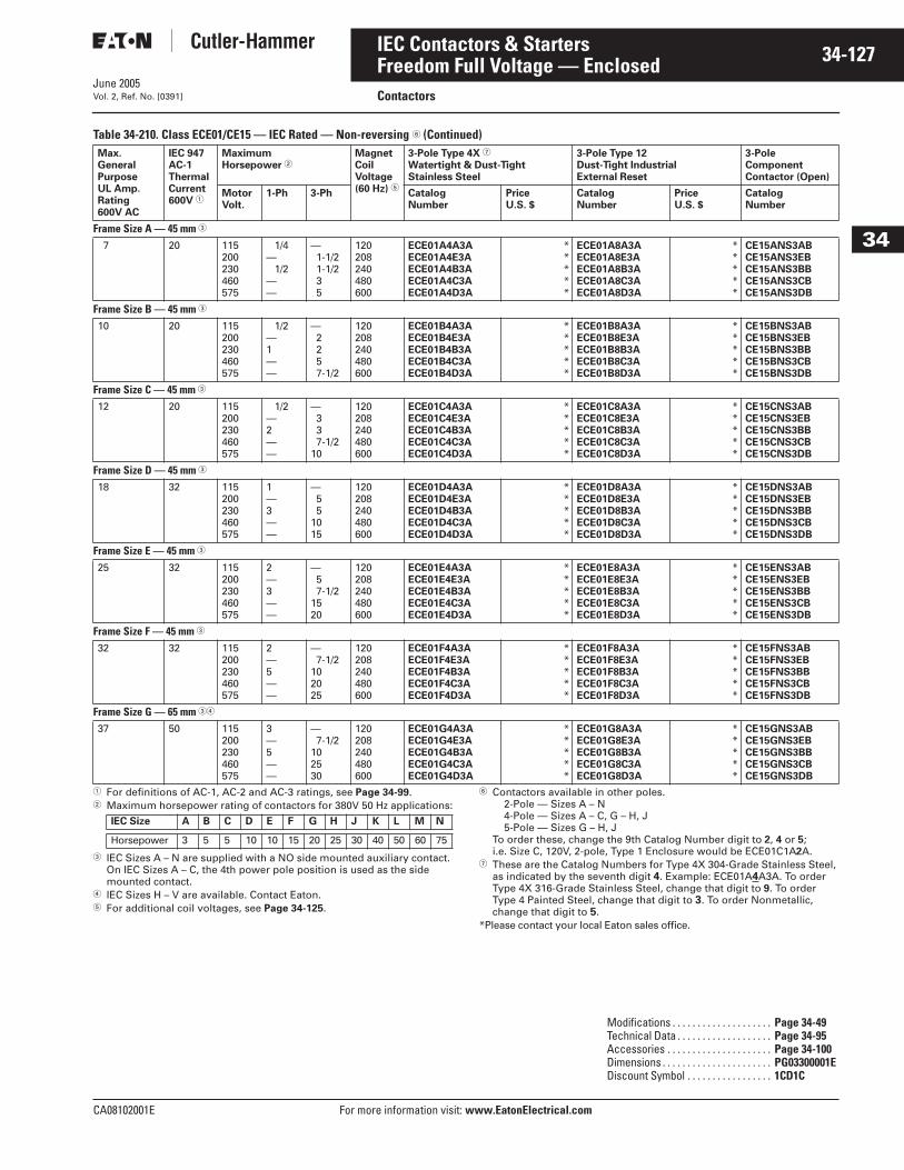
June 2005
CA08102001E For more information visit: www.EatonElectrical.com
34-127IEC Contactors & Starters
34
Freedom Full Voltage — EnclosedContactorsVol. 2, Ref. No. [0391]
Table 34-210. Class ECE01/CE15 — IEC Rated — Non-reversing � (Continued)
� For definitions of AC-1, AC-2 and AC-3 ratings, see Page 34-99.� Maximum horsepower rating of contactors for 380V 50 Hz applications:
� IEC Sizes A – N are supplied with a NO side mounted auxiliary contact. On IEC Sizes A – C, the 4th power pole position is used as the side mounted contact.
� IEC Sizes H – V are available. Contact Eaton.� For additional coil voltages, see Page 34-125.
� Contactors available in other poles.2-Pole — Sizes A – N4-Pole — Sizes A – C, G – H, J5-Pole — Sizes G – H, J
To order these, change the 9th Catalog Number digit to 2, 4 or 5; i.e. Size C, 120V, 2-pole, Type 1 Enclosure would be ECE01C1A2A.
� These are the Catalog Numbers for Type 4X 304-Grade Stainless Steel, as indicated by the seventh digit 4. Example: ECE01A4A3A. To order Type 4X 316-Grade Stainless Steel, change that digit to 9. To order Type 4 Painted Steel, change that digit to 3. To order Nonmetallic, change that digit to 5.
*Please contact your local Eaton sales office.
Max.GeneralPurposeUL Amp.Rating600V AC
IEC 947AC-1ThermalCurrent600V �
MaximumHorsepower �
MagnetCoilVoltage(60 Hz) �
3-Pole Type 4X �
Watertight & Dust-TightStainless Steel
3-Pole Type 12Dust-Tight IndustrialExternal Reset
3-PoleComponentContactor (Open)
MotorVolt.
1-Ph 3-Ph CatalogNumber
PriceU.S. $
CatalogNumber
PriceU.S. $
CatalogNumber
Frame Size A — 45 mm �
7 20 115200230460575
1/4— 1/2
——
—1-1/21-1/235
120 208240480600
ECE01A4A3AECE01A4E3AECE01A4B3AECE01A4C3AECE01A4D3A
*****
ECE01A8A3AECE01A8E3AECE01A8B3AECE01A8C3AECE01A8D3A
*****
CE15ANS3ABCE15ANS3EBCE15ANS3BBCE15ANS3CBCE15ANS3DB
Frame Size B — 45 mm �
10 20 115200230460575
1/2—1——
—2257-1/2
120 208240480600
ECE01B4A3AECE01B4E3AECE01B4B3AECE01B4C3AECE01B4D3A
*****
ECE01B8A3AECE01B8E3AECE01B8B3AECE01B8C3AECE01B8D3A
*****
CE15BNS3ABCE15BNS3EBCE15BNS3BBCE15BNS3CBCE15BNS3DB
Frame Size C — 45 mm �
12 20 115200230460575
1/2—2——
—337-1/2
10
120 208240480600
ECE01C4A3AECE01C4E3AECE01C4B3AECE01C4C3AECE01C4D3A
*****
ECE01C8A3AECE01C8E3AECE01C8B3AECE01C8C3AECE01C8D3A
*****
CE15CNS3ABCE15CNS3EBCE15CNS3BBCE15CNS3CBCE15CNS3DB
Frame Size D — 45 mm �
18 32 115200230460575
1—3——
—55
1015
120 208240480600
ECE01D4A3AECE01D4E3AECE01D4B3AECE01D4C3AECE01D4D3A
*****
ECE01D8A3AECE01D8E3AECE01D8B3AECE01D8C3AECE01D8D3A
*****
CE15DNS3ABCE15DNS3EBCE15DNS3BBCE15DNS3CBCE15DNS3DB
Frame Size E — 45 mm �
25 32 115200230460575
2—3——
—57-1/2
1520
120 208240480600
ECE01E4A3AECE01E4E3AECE01E4B3AECE01E4C3AECE01E4D3A
*****
ECE01E8A3AECE01E8E3AECE01E8B3AECE01E8C3AECE01E8D3A
*****
CE15ENS3ABCE15ENS3EBCE15ENS3BBCE15ENS3CBCE15ENS3DB
Frame Size F — 45 mm �
32 32 115200230460575
2—5——
—7-1/2
102025
120 208240480600
ECE01F4A3AECE01F4E3AECE01F4B3AECE01F4C3AECE01F4D3A
*****
ECE01F8A3AECE01F8E3AECE01F8B3AECE01F8C3AECE01F8D3A
*****
CE15FNS3ABCE15FNS3EBCE15FNS3BBCE15FNS3CBCE15FNS3DB
Frame Size G — 65 mm ��
37 50 115200230460575
3—5——
—7-1/2
102530
120 208240480600
ECE01G4A3AECE01G4E3AECE01G4B3AECE01G4C3AECE01G4D3A
*****
ECE01G8A3AECE01G8E3AECE01G8B3AECE01G8C3AECE01G8D3A
*****
CE15GNS3ABCE15GNS3EBCE15GNS3BBCE15GNS3CBCE15GNS3DB
IEC Size A B C D E F G H J K L M N
Horsepower 3 5 5 10 10 15 20 25 30 40 50 60 75
Modifications . . . . . . . . . . . . . . . . . . . . Page 34-49Technical Data . . . . . . . . . . . . . . . . . . . Page 34-95Accessories . . . . . . . . . . . . . . . . . . . . . Page 34-100Dimensions . . . . . . . . . . . . . . . . . . . . . . PG03300001EDiscount Symbol . . . . . . . . . . . . . . . . . 1CD1C
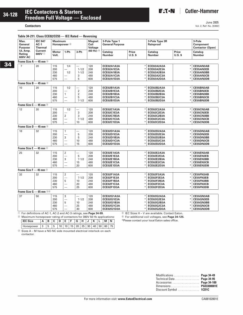
June 2005
34-128
For more information visit: www.EatonElectrical.com CA08102001E
IEC Contactors & Starters
34
Freedom Full Voltage — EnclosedContactors Vol. 2, Ref. No. [0392]
Table 34-211. Class ECE02/CE55 — IEC Rated — Reversing
� For definitions of AC-1, AC-2 and AC-3 ratings, see Page 34-99.� Maximum horsepower rating of contactors for 380V 50 Hz applications:
� Sizes A – M have a NO-NC side mounted electrical interlock on each contactor.
� IEC Sizes H – V are available. Contact Eaton.� For additional coil voltages, see Page 34-125.*Please contact your local Eaton sales office.
Max.GeneralPurposeUL Amp.Rating600V AC
IEC 947AC-1ThermalCurrent600V �
MaximumHorsepower �
MagnetCoilVoltage(60 Hz) �
3-Pole Type 1General Purpose
3-Pole Type 3RRainproof
3-PoleComponentContactor (Open)
MotorVolt.
1-Ph 3-Ph CatalogNumber
PriceU.S. $
CatalogNumber
PriceU.S. $
CatalogNumber
Frame Size A — 45 mm �
7 20 115200230460575
1/4— 1/2
——
—1-1/21-1/235
120 208240480600
ECE02A1A3AECE02A1E3AECE02A1B3AECE02A1C3AECE02A1D3A
*****
ECE02A2A3AECE02A2E3AECE02A2B3AECE02A2C3AECE02A2D3A
*****
CE55AN3ABCE55AN3EBCE55AN3BBCE55AN3CBCE55AN3DB
Frame Size B — 45 mm �
10 20 115200230460575
1/2—1——
—2257-1/2
120 208240480600
ECE02B1A3AECE02B1E3AECE02B1B3AECE02B1C3AECE02B1D3A
*****
ECE02B2A3AECE02B2E3AECE02B2B3AECE02B2C3AECE02B2D3A
*****
CE55BN3ABCE55BN3EBCE55BN3BBCE55BN3CBCE55BN3DB
Frame Size C — 45 mm �
12 20 115200230460575
1/2—2——
—337-1/2
10
120 208240480600
ECE02C1A3AECE02C1E3AECE02C1B3AECE02C1C3AECE02C1D3A
*****
ECE02C2A3AECE02C2E3AECE02C2B3AECE02C2C3AECE02C2D3A
*****
CE55CN3ABCE55CN3EBCE55CN3BBCE55CN3CBCE55CN3DB
Frame Size D — 45 mm �
18 32 115200230460575
1—3——
—55
1015
120 208240480600
ECE02D1A3AECE02D1E3AECE02D1B3AECE02D1C3AECE02D1D3A
*****
ECE02D2A3AECE02D2E3AECE02D2B3AECE02D2C3AECE02D2D3A
*****
CE55DN3ABCE55DN3EBCE55DN3BBCE55DN3CBCE55DN3DB
Frame Size E — 45 mm �
25 32 115200230460575
2—3——
—57-1/2
1520
120 208240480600
ECE02E1A3AECE02E1E3AECE02E1B3AECE02E1C3AECE02E1D3A
*****
ECE02E2A3AECE02E2E3AECE02E2B3AECE02E2C3AECE02E2D3A
*****
CE55EN3ABCE55EN3EBCE55EN3BBCE55EN3CBCE55EN3DB
Frame Size F — 45 mm �
32 32 115200230460575
2—5——
—7-1/2
102025
120 208240480600
ECE02F1A3AECE02F1E3AECE02F1B3AECE02F1C3AECE02F1D3A
*****
ECE02F2A3AECE02F2E3AECE02F2B3AECE02F2C3AECE02F2D3A
*****
CE55FN3ABCE55FN3EBCE55FN3BBCE55FN3CBCE55FN3DB
Frame Size G — 65 mm ��
37 50 115200230460575
3—5——
—7-1/2
102530
120 208240480600
ECE02G1A3AECE02G1E3AECE02G1B3AECE02G1C3AECE02G1D3A
*****
ECE02G2A3AECE02G2E3AECE02G2B3AECE02G2C3AECE02G2D3A
*****
CE55GN3ABCE55GN3EBCE55GN3BBCE55GN3CBCE55GN3DB
IEC Size A B C D E F G H J K L M N
Horsepower 3 5 5 10 10 15 20 25 30 40 50 60 75
Modifications . . . . . . . . . . . . . . . . . . . Page 34-49Technical Data . . . . . . . . . . . . . . . . . . Page 34-95Accessories . . . . . . . . . . . . . . . . . . . . Page 34-100Dimensions . . . . . . . . . . . . . . . . . . . . . PG03300001EDiscount Symbol . . . . . . . . . . . . . . . . 1CD1C
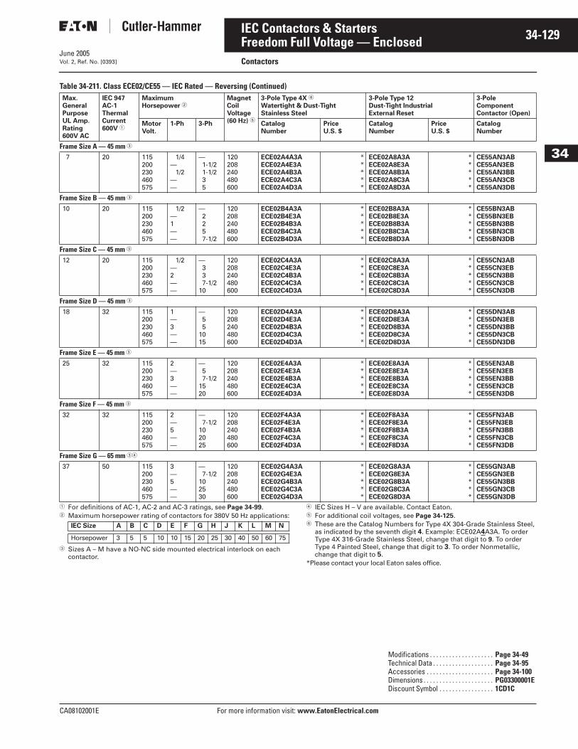
June 2005
CA08102001E For more information visit: www.EatonElectrical.com
34-129IEC Contactors & Starters
34
Freedom Full Voltage — EnclosedContactorsVol. 2, Ref. No. [0393]
Table 34-211. Class ECE02/CE55 — IEC Rated — Reversing (Continued)
� For definitions of AC-1, AC-2 and AC-3 ratings, see Page 34-99.� Maximum horsepower rating of contactors for 380V 50 Hz applications:
� Sizes A – M have a NO-NC side mounted electrical interlock on each contactor.
� IEC Sizes H – V are available. Contact Eaton.� For additional coil voltages, see Page 34-125.� These are the Catalog Numbers for Type 4X 304-Grade Stainless Steel,
as indicated by the seventh digit 4. Example: ECE02A4A3A. To order Type 4X 316-Grade Stainless Steel, change that digit to 9. To order Type 4 Painted Steel, change that digit to 3. To order Nonmetallic, change that digit to 5.
*Please contact your local Eaton sales office.
Max.GeneralPurposeUL Amp.Rating600V AC
IEC 947AC-1ThermalCurrent600V �
MaximumHorsepower �
MagnetCoilVoltage(60 Hz) �
3-Pole Type 4X �
Watertight & Dust-TightStainless Steel
3-Pole Type 12Dust-Tight IndustrialExternal Reset
3-PoleComponentContactor (Open)
MotorVolt.
1-Ph 3-Ph CatalogNumber
PriceU.S. $
CatalogNumber
PriceU.S. $
CatalogNumber
Frame Size A — 45 mm �
7 20 115200230460575
1/4— 1/2
——
—1-1/21-1/235
120 208240480600
ECE02A4A3AECE02A4E3AECE02A4B3AECE02A4C3AECE02A4D3A
*****
ECE02A8A3AECE02A8E3AECE02A8B3AECE02A8C3AECE02A8D3A
*****
CE55AN3ABCE55AN3EBCE55AN3BBCE55AN3CBCE55AN3DB
Frame Size B — 45 mm �
10 20 115200230460575
1/2—1——
—2257-1/2
120 208240480600
ECE02B4A3AECE02B4E3AECE02B4B3AECE02B4C3AECE02B4D3A
*****
ECE02B8A3AECE02B8E3AECE02B8B3AECE02B8C3AECE02B8D3A
*****
CE55BN3ABCE55BN3EBCE55BN3BBCE55BN3CBCE55BN3DB
Frame Size C — 45 mm �
12 20 115200230460575
1/2—2——
—337-1/2
10
120 208240480600
ECE02C4A3AECE02C4E3AECE02C4B3AECE02C4C3AECE02C4D3A
*****
ECE02C8A3AECE02C8E3AECE02C8B3AECE02C8C3AECE02C8D3A
*****
CE55CN3ABCE55CN3EBCE55CN3BBCE55CN3CBCE55CN3DB
Frame Size D — 45 mm �
18 32 115200230460575
1—3——
—55
1015
120 208240480600
ECE02D4A3AECE02D4E3AECE02D4B3AECE02D4C3AECE02D4D3A
*****
ECE02D8A3AECE02D8E3AECE02D8B3AECE02D8C3AECE02D8D3A
*****
CE55DN3ABCE55DN3EBCE55DN3BBCE55DN3CBCE55DN3DB
Frame Size E — 45 mm �
25 32 115200230460575
2—3——
—57-1/2
1520
120 208240480600
ECE02E4A3AECE02E4E3AECE02E4B3AECE02E4C3AECE02E4D3A
*****
ECE02E8A3AECE02E8E3AECE02E8B3AECE02E8C3AECE02E8D3A
*****
CE55EN3ABCE55EN3EBCE55EN3BBCE55EN3CBCE55EN3DB
Frame Size F — 45 mm �
32 32 115200230460575
2—5——
—7-1/2
102025
120 208240480600
ECE02F4A3AECE02F4E3AECE02F4B3AECE02F4C3AECE02F4D3A
*****
ECE02F8A3AECE02F8E3AECE02F8B3AECE02F8C3AECE02F8D3A
*****
CE55FN3ABCE55FN3EBCE55FN3BBCE55FN3CBCE55FN3DB
Frame Size G — 65 mm ��
37 50 115200230460575
3—5——
—7-1/2
102530
120 208240480600
ECE02G4A3AECE02G4E3AECE02G4B3AECE02G4C3AECE02G4D3A
*****
ECE02G8A3AECE02G8E3AECE02G8B3AECE02G8C3AECE02G8D3A
*****
CE55GN3ABCE55GN3EBCE55GN3BBCE55GN3CBCE55GN3DB
IEC Size A B C D E F G H J K L M N
Horsepower 3 5 5 10 10 15 20 25 30 40 50 60 75
Modifications . . . . . . . . . . . . . . . . . . . . Page 34-49Technical Data . . . . . . . . . . . . . . . . . . . Page 34-95Accessories . . . . . . . . . . . . . . . . . . . . . Page 34-100Dimensions . . . . . . . . . . . . . . . . . . . . . . PG03300001EDiscount Symbol . . . . . . . . . . . . . . . . . 1CD1C
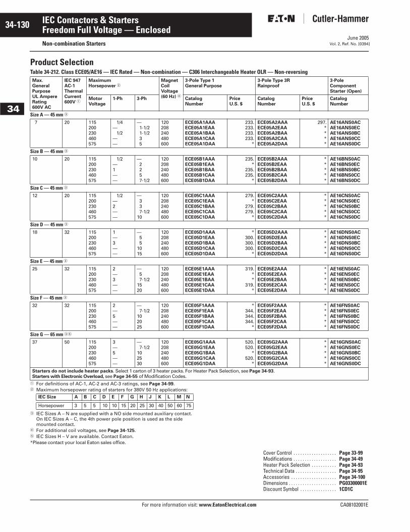
June 2005
34-130
For more information visit: www.EatonElectrical.com CA08102001E
IEC Contactors & Starters
34
Freedom Full Voltage — EnclosedNon-combination Starters Vol. 2, Ref. No. [0394]
Product SelectionTable 34-212. Class ECE05/AE16 — IEC Rated — Non-combination — C306 Interchangeable Heater OLR — Non-reversing
� For definitions of AC-1, AC-2 and AC-3 ratings, see Page 34-99.� Maximum horsepower rating of starters for 380V 50 Hz applications:
� IEC Sizes A – N are supplied with a NO side mounted auxiliary contact. On IEC Sizes A – C, the 4th power pole position is used as the side mounted contact.
� For additional coil voltages, see Page 34-125.� IEC Sizes H – V are available. Contact Eaton.*Please contact your local Eaton sales office.
Max.GeneralPurposeUL AmpereRating600V AC
IEC 947AC-1ThermalCurrent600V �
MaximumHorsepower �
MagnetCoilVoltage(60 Hz) �
3-Pole Type 1General Purpose
3-Pole Type 3RRainproof
3-Pole Component Starter (Open)
MotorVoltage
1-Ph 3-Ph CatalogNumber
PriceU.S. $
CatalogNumber
PriceU.S. $
CatalogNumber
Size A — 45 mm �
7 20 115200230460575
1/4— 1/2
——
—1-1/21-1/235
120 208240480600
ECE05A1AAAECE05A1EAAECE05A1BAAECE05A1CAAECE05A1DAA
233.233.233.233.
*
ECE05A2AAAECE05A2EAAECE05A2BAAECE05A2CAAECE05A2DAA
297.****
AE16ANS0ACAE16ANS0ECAE16ANS0BCAE16ANS0CCAE16ANS0DC
Size B — 45 mm �
10 20 115200230460575
1/2—1——
—2257-1/2
120 208240480600
ECE05B1AAAECE05B1EAAECE05B1BAAECE05B1CAAECE05B1DAA
235.*
235.235.
*
ECE05B2AAAECE05B2EAAECE05B2BAAECE05B2CAAECE05B2DAA
*****
AE16BNS0ACAE16BNS0ECAE16BNS0BCAE16BNS0CCAE16BNS0DC
Size C — 45 mm �
12 20 115200230460575
1/2—2——
—337-1/2
10
120 208240480600
ECE05C1AAAECE05C1EAAECE05C1BAAECE05C1CAAECE05C1DAA
279.*
279.279.
*
ECE05C2AAAECE05C2EAAECE05C2BAAECE05C2CAAECE05C2DAA
*****
AE16CNS0ACAE16CNS0ECAE16CNS0BCAE16CNS0CCAE16CNS0DC
Size D — 45 mm �
18 32 115200230460575
1—3——
—55
1015
120 208240480600
ECE05D1AAAECE05D1EAAECE05D1BAAECE05D1CAAECE05D1DAA
*300.300.300.
*
ECE05D2AAAECE05D2EAAECE05D2BAAECE05D2CAAECE05D2DAA
*****
AE16DNS0ACAE16DNS0ECAE16DNS0BCAE16DNS0CCAE16DNS0DC
Size E — 45 mm �
25 32 115200230460575
2—3——
—57-1/2
1520
120 208240480600
ECE05E1AAAECE05E1EAAECE05E1BAAECE05E1CAAECE05E1DAA
319.**
319.*
ECE05E2AAAECE05E2EAAECE05E2BAAECE05E2CAAECE05E2DAA
*****
AE16ENS0ACAE16ENS0ECAE16ENS0BCAE16ENS0CCAE16ENS0DC
Size F — 45 mm �
32 32 115200230460575
2—5——
—7-1/2
102025
120 208240480600
ECE05F1AAAECE05F1EAAECE05F1BAAECE05F1CAAECE05F1DAA
*344.344.344.
*
ECE05F2AAAECE05F2EAAECE05F2BAAECE05F2CAAECE05F2DAA
*****
AE16FNS0ACAE16FNS0ECAE16FNS0BCAE16FNS0CCAE16FNS0DC
Size G — 65 mm ��
37 50 115200230460575
3—5——
—7-1/2
102530
120 208240480600
ECE05G1AAAECE05G1EAAECE05G1BAAECE05G1CAAECE05G1DAA
520.520.
*520.
*
ECE05G2AAAECE05G2EAAECE05G2BAAECE05G2CAAECE05G2DAA
*****
AE16GNS0ACAE16GNS0ECAE16GNS0BCAE16GNS0CCAE16GNS0DC
Starters do not include heater packs. Select 1 carton of 3 heater packs. For Heater Pack Selection, see Page 34-93.Starters with Electronic Overload, see Page 34-55 of Modification Codes.
IEC Size A B C D E F G H J K L M N
Horsepower 3 5 5 10 10 15 20 25 30 40 50 60 75
Cover Control . . . . . . . . . . . . . . . . . . . Page 33-99Modifications . . . . . . . . . . . . . . . . . . . Page 34-49Heater Pack Selection . . . . . . . . . . . Page 34-93Technical Data . . . . . . . . . . . . . . . . . . Page 34-95Accessories . . . . . . . . . . . . . . . . . . . . Page 34-100Dimensions . . . . . . . . . . . . . . . . . . . . . PG03300001EDiscount Symbol . . . . . . . . . . . . . . . . 1CD1C

June 2005
CA08102001E For more information visit: www.EatonElectrical.com
34-131IEC Contactors & Starters
34
Freedom Full Voltage — EnclosedNon-combination StartersVol. 2, Ref. No. [0395]
Table 34-212. Class ECE05/AE16 — IEC Rated — Non-combination — C306 Interchangeable Heater OLR — Non-reversing (Continued)
� For definitions of AC-1, AC-2 and AC-3 ratings, see Page 34-99.� Maximum horsepower rating of starters for 380V 50 Hz applications:
� IEC Sizes A – N are supplied with a NO side mounted auxiliary contact. On IEC Sizes A – C, the 4th power pole position is used as the side mounted contact.
� For additional coil voltages, see Page 34-125.
� IEC Sizes H – V are available. Contact Eaton.� These are the Catalog Numbers for Type 4X 304-Grade Stainless Steel,
as indicated by the seventh digit 4. Example: ECE05A4AAA. To order Type 4X 316-Grade Stainless Steel, change that digit to 9. To order Type 4 Painted Steel, change that digit to 3. To order Nonmetallic, change that digit to 5.
*Please contact your local Eaton sales office.
Max.GeneralPurposeUL AmpereRating600V AC
IEC 947AC-1ThermalCurrent600V �
MaximumHorsepower �
MagnetCoilVoltage(60 Hz) �
3-Pole Type 4X �
Watertight & Dust-TightStainless Steel
3-Pole Type 12Dust-Tight Industrial External Reset
3-Pole Component Starter (Open)
MotorVoltage
1-Ph 3-Ph CatalogNumber
PriceU.S. $
CatalogNumber
PriceU.S. $
CatalogNumber
Size A — 45 mm �
7 20 115200230460575
1/4— 1/2
——
—1-1/21-1/235
120 208240480600
ECE05A4AAAECE05A4EAAECE05A4BAAECE05A4CAAECE05A4DAA
*****
ECE05A8AAAECE05A8EAAECE05A8BAAECE05A8CAAECE05A8DAA
297.****
AE16ANS0ACAE16ANS0ECAE16ANS0BCAE16ANS0CCAE16ANS0DC
Size B — 45 mm �
10 20 115200230460575
1/2—1——
—2257-1/2
120 208240480600
ECE05B4AAAECE05B4EAAECE05B4BAAECE05B4CAAECE05B4DAA
*****
ECE05B8AAAECE05B8EAAECE05B8BAAECE05B8CAAECE05B8DAA
301.****
AE16BNS0ACAE16BNS0ECAE16BNS0BCAE16BNS0CCAE16BNS0DC
Size C — 45 mm �
12 20 115200230460575
1/2—2——
—337-1/2
10
120 208240480600
ECE05C4AAAECE05C4EAAECE05C4BAAECE05C4CAAECE05C4DAA
*****
ECE05C8AAAECE05C8EAAECE05C8BAAECE05C8CAAECE05C8DAA
333.****
AE16CNS0ACAE16CNS0ECAE16CNS0BCAE16CNS0CCAE16CNS0DC
Size D — 45 mm �
18 32 115200230460575
1—3——
—55
1015
120 208240480600
ECE05D4AAAECE05D4EAAECE05D4BAAECE05D4CAAECE05D4DAA
*****
ECE05D8AAAECE05D8EAAECE05D8BAAECE05D8CAAECE05D8DAA
*****
AE16DNS0ACAE16DNS0ECAE16DNS0BCAE16DNS0CCAE16DNS0DC
Size E — 45 mm �
25 32 115200230460575
2—3——
—57-1/2
1520
120 208240480600
ECE05E4AAAECE05E4EAAECE05E4BAAECE05E4CAAECE05E4DAA
*****
ECE05E8AAAECE05E8EAAECE05E8BAAECE05E8CAAECE05E8DAA
**
371.**
AE16ENS0ACAE16ENS0ECAE16ENS0BCAE16ENS0CCAE16ENS0DC
Size F — 45 mm �
32 32 115200230460575
2—5——
—7-1/2
102025
120 208240480600
ECE05F4AAAECE05F4EAAECE05F4BAAECE05F4CAAECE05F4DAA
*****
ECE05F8AAAECE05F8EAAECE05F8BAAECE05F8CAAECE05F8DAA
***
424.*
AE16FNS0ACAE16FNS0ECAE16FNS0BCAE16FNS0CCAE16FNS0DC
Size G — 65 mm ��
37 50 115200230460575
3—5——
—7-1/2
102530
120 208240480600
ECE05G4AAAECE05G4EAAECE05G4BAAECE05G4CAAECE05G4DAA
*****
ECE05G8AAAECE05G8EAAECE05G8BAAECE05G8CAAECE05G8DAA
665.****
AE16GNS0ACAE16GNS0ECAE16GNS0BCAE16GNS0CCAE16GNS0DC
Starters do not include heater packs. Select 1 carton of 3 heater packs. For Heater Pack Selection, see Page 34-93.Starters with Electronic Overload, see Page 34-55 of Modification Codes.
IEC Size A B C D E F G H J K L M N
Horsepower 3 5 5 10 10 15 20 25 30 40 50 60 75
Cover Control . . . . . . . . . . . . . . . . . . . . Page 33-99Modifications . . . . . . . . . . . . . . . . . . . . Page 34-49Heater Pack Selection . . . . . . . . . . . . Page 34-93Technical Data . . . . . . . . . . . . . . . . . . . Page 34-95Accessories . . . . . . . . . . . . . . . . . . . . . Page 34-100Dimensions . . . . . . . . . . . . . . . . . . . . . . PG03300001EDiscount Symbol . . . . . . . . . . . . . . . . . 1CD1C
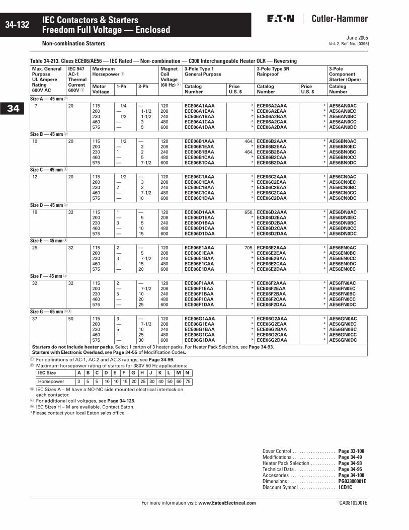
June 2005
34-132
For more information visit: www.EatonElectrical.com CA08102001E
IEC Contactors & Starters
34
Freedom Full Voltage — EnclosedNon-combination Starters Vol. 2, Ref. No. [0396]
Table 34-213. Class ECE06/AE56 — IEC Rated — Non-combination — C306 Interchangeable Heater OLR — Reversing
� For definitions of AC-1, AC-2 and AC-3 ratings, see Page 34-99.� Maximum horsepower rating of starters for 380V 50 Hz applications:
� IEC Sizes A – M have a NO-NC side mounted electrical interlock on each contactor.
� For additional coil voltages, see Page 34-125.� IEC Sizes H – M are available. Contact Eaton. *Please contact your local Eaton sales office.
Max. GeneralPurposeUL AmpereRating600V AC
IEC 947AC-1ThermalCurrent600V �
MaximumHorsepower �
MagnetCoilVoltage(60 Hz) �
3-Pole Type 1General Purpose
3-Pole Type 3RRainproof
3-Pole Component Starter (Open)
MotorVoltage
1-Ph 3-Ph CatalogNumber
PriceU.S. $
CatalogNumber
PriceU.S. $
CatalogNumber
Size A — 45 mm �
7 20 115200230460575
1/4— 1/2
——
—1-1/21-1/235
120 208240480600
ECE06A1AAAECE06A1EAAECE06A1BAAECE06A1CAAECE06A1DAA
*****
ECE06A2AAAECE06A2EAAECE06A2BAAECE06A2CAAECE06A2DAA
*****
AE56AN0ACAE56AN0ECAE56AN0BCAE56AN0CCAE56AN0DC
Size B — 45 mm �
10 20 115200230460575
1/2—1——
—2257-1/2
120 208240480600
ECE06B1AAAECE06B1EAAECE06B1BAAECE06B1CAAECE06B1DAA
464.*
464.**
ECE06B2AAAECE06B2EAAECE06B2BAAECE06B2CAAECE06B2DAA
*****
AE56BN0ACAE56BN0ECAE56BN0BCAE56BN0CCAE56BN0DC
Size C — 45 mm �
12 20 115200230460575
1/2—2——
—337-1/2
10
120 208240480600
ECE06C1AAAECE06C1EAAECE06C1BAAECE06C1CAAECE06C1DAA
*****
ECE06C2AAAECE06C2EAAECE06C2BAAECE06C2CAAECE06C2DAA
*****
AE56CN0ACAE56CN0ECAE56CN0BCAE56CN0CCAE56CN0DC
Size D — 45 mm �
18 32 115200230460575
1—3——
—55
1015
120 208240480600
ECE06D1AAAECE06D1EAAECE06D1BAAECE06D1CAAECE06D1DAA
650.****
ECE06D2AAAECE06D2EAAECE06D2BAAECE06D2CAAECE06D2DAA
*****
AE56DN0ACAE56DN0ECAE56DN0BCAE56DN0CCAE56DN0DC
Size E — 45 mm �
25 32 115200230460575
2—3——
—57-1/2
1520
120 208240480600
ECE06E1AAAECE06E1EAAECE06E1BAAECE06E1CAAECE06E1DAA
705.****
ECE06E2AAAECE06E2EAAECE06E2BAAECE06E2CAAECE06E2DAA
*****
AE56EN0ACAE56EN0BCAE56EN0CCAE56EN0DCAE56EN0EC
Size F — 45 mm �
32 32 115200230460575
2—5——
—7-1/2
102025
120 208240480600
ECE06F1AAAECE06F1EAAECE06F1BAAECE06F1CAAECE06F1DAA
*****
ECE06F2AAAECE06F2EAAECE06F2BAAECE06F2CAAECE06F2DAA
*****
AE56FN0ACAE56FN0ECAE56FN0BCAE56FN0CCAE56FN0DC
Size G — 65 mm ��
37 50 115200230460575
3—5——
—7-1/2
102530
120 208240480600
ECE06G1AAAECE06G1EAAECE06G1BAAECE06G1CAAECE06G1DAA
*****
ECE06G2AAAECE06G2EAAECE06G2BAAECE06G2CAAECE06G2DAA
*****
AE56GN0ACAE56GN0ECAE56GN0BCAE56GN0CCAE56GN0DC
Starters do not include heater packs. Select 1 carton of 3 heater packs. For Heater Pack Selection, see Page 34-93.Starters with Electronic Overload, see Page 34-55 of Modification Codes.
IEC Size A B C D E F G H J K L M N
Horsepower 3 5 5 10 10 15 20 25 30 40 50 60 75
Cover Control . . . . . . . . . . . . . . . . . . . Page 33-100Modifications . . . . . . . . . . . . . . . . . . . Page 34-49Heater Pack Selection . . . . . . . . . . . Page 34-93Technical Data . . . . . . . . . . . . . . . . . . Page 34-95Accessories . . . . . . . . . . . . . . . . . . . . Page 34-100Dimensions . . . . . . . . . . . . . . . . . . . . . PG03300001EDiscount Symbol . . . . . . . . . . . . . . . . 1CD1C
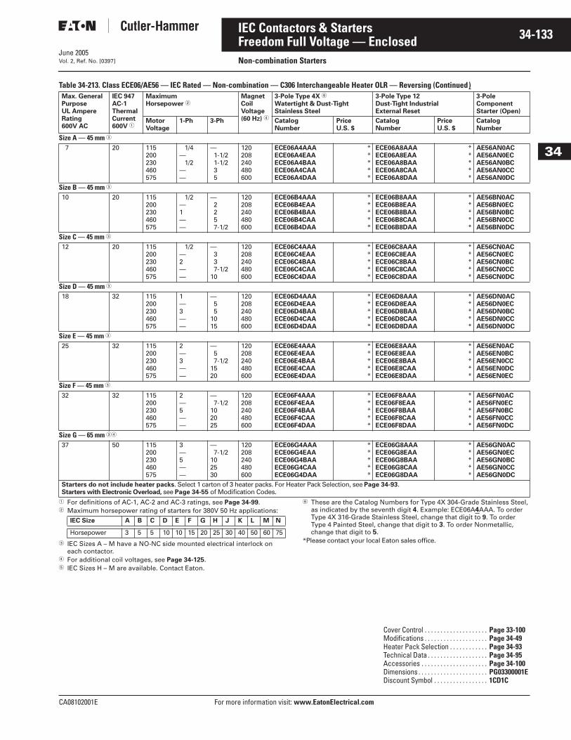
June 2005
CA08102001E For more information visit: www.EatonElectrical.com
34-133IEC Contactors & Starters
34
Freedom Full Voltage — EnclosedNon-combination StartersVol. 2, Ref. No. [0397]
Table 34-213. Class ECE06/AE56 — IEC Rated — Non-combination — C306 Interchangeable Heater OLR — Reversing (Continued)
� For definitions of AC-1, AC-2 and AC-3 ratings, see Page 34-99.� Maximum horsepower rating of starters for 380V 50 Hz applications:
� IEC Sizes A – M have a NO-NC side mounted electrical interlock on each contactor.
� For additional coil voltages, see Page 34-125.� IEC Sizes H – M are available. Contact Eaton.
� These are the Catalog Numbers for Type 4X 304-Grade Stainless Steel, as indicated by the seventh digit 4. Example: ECE06A4AAA. To order Type 4X 316-Grade Stainless Steel, change that digit to 9. To order Type 4 Painted Steel, change that digit to 3. To order Nonmetallic, change that digit to 5.
*Please contact your local Eaton sales office.
Max. GeneralPurposeUL AmpereRating600V AC
IEC 947AC-1ThermalCurrent600V �
MaximumHorsepower �
MagnetCoilVoltage(60 Hz) �
3-Pole Type 4X �
Watertight & Dust-TightStainless Steel
3-Pole Type 12Dust-Tight IndustrialExternal Reset
3-Pole Component Starter (Open)
MotorVoltage
1-Ph 3-Ph CatalogNumber
PriceU.S. $
CatalogNumber
PriceU.S. $
CatalogNumber
Size A — 45 mm �
7 20 115200230460575
1/4— 1/2
——
—1-1/21-1/235
120 208240480600
ECE06A4AAAECE06A4EAAECE06A4BAAECE06A4CAAECE06A4DAA
*****
ECE06A8AAAECE06A8EAAECE06A8BAAECE06A8CAAECE06A8DAA
*****
AE56AN0ACAE56AN0ECAE56AN0BCAE56AN0CCAE56AN0DC
Size B — 45 mm �
10 20 115200230460575
1/2—1——
—2257-1/2
120 208240480600
ECE06B4AAAECE06B4EAAECE06B4BAAECE06B4CAAECE06B4DAA
*****
ECE06B8AAAECE06B8EAAECE06B8BAAECE06B8CAAECE06B8DAA
*****
AE56BN0ACAE56BN0ECAE56BN0BCAE56BN0CCAE56BN0DC
Size C — 45 mm �
12 20 115200230460575
1/2—2——
—337-1/2
10
120 208240480600
ECE06C4AAAECE06C4EAAECE06C4BAAECE06C4CAAECE06C4DAA
*****
ECE06C8AAAECE06C8EAAECE06C8BAAECE06C8CAAECE06C8DAA
*****
AE56CN0ACAE56CN0ECAE56CN0BCAE56CN0CCAE56CN0DC
Size D — 45 mm �
18 32 115200230460575
1—3——
—55
1015
120 208240480600
ECE06D4AAAECE06D4EAAECE06D4BAAECE06D4CAAECE06D4DAA
*****
ECE06D8AAAECE06D8EAAECE06D8BAAECE06D8CAAECE06D8DAA
*****
AE56DN0ACAE56DN0ECAE56DN0BCAE56DN0CCAE56DN0DC
Size E — 45 mm �
25 32 115200230460575
2—3——
—57-1/2
1520
120 208240480600
ECE06E4AAAECE06E4EAAECE06E4BAAECE06E4CAAECE06E4DAA
*****
ECE06E8AAAECE06E8EAAECE06E8BAAECE06E8CAAECE06E8DAA
*****
AE56EN0ACAE56EN0BCAE56EN0CCAE56EN0DCAE56EN0EC
Size F — 45 mm �
32 32 115200230460575
2—5——
—7-1/2
102025
120 208240480600
ECE06F4AAAECE06F4EAAECE06F4BAAECE06F4CAAECE06F4DAA
*****
ECE06F8AAAECE06F8EAAECE06F8BAAECE06F8CAAECE06F8DAA
*****
AE56FN0ACAE56FN0ECAE56FN0BCAE56FN0CCAE56FN0DC
Size G — 65 mm ��
37 50 115200230460575
3—5——
—7-1/2
102530
120 208240480600
ECE06G4AAAECE06G4EAAECE06G4BAAECE06G4CAAECE06G4DAA
*****
ECE06G8AAAECE06G8EAAECE06G8BAAECE06G8CAAECE06G8DAA
*****
AE56GN0ACAE56GN0ECAE56GN0BCAE56GN0CCAE56GN0DC
Starters do not include heater packs. Select 1 carton of 3 heater packs. For Heater Pack Selection, see Page 34-93.Starters with Electronic Overload, see Page 34-55 of Modification Codes.
IEC Size A B C D E F G H J K L M N
Horsepower 3 5 5 10 10 15 20 25 30 40 50 60 75
Cover Control . . . . . . . . . . . . . . . . . . . . Page 33-100Modifications . . . . . . . . . . . . . . . . . . . . Page 34-49Heater Pack Selection . . . . . . . . . . . . Page 34-93Technical Data . . . . . . . . . . . . . . . . . . . Page 34-95Accessories . . . . . . . . . . . . . . . . . . . . . Page 34-100Dimensions . . . . . . . . . . . . . . . . . . . . . . PG03300001EDiscount Symbol . . . . . . . . . . . . . . . . . 1CD1C

June 2005
34-134
For more information visit: www.EatonElectrical.com CA08102001E
IEC Contactors & Starters
34
Freedom Full Voltage — EnclosedNon-combination Starters Vol. 2, Ref. No. [0398]
Table 34-214. Class ECE09/AE17 — IEC Rated — Non-combination — Fixed Heater OLR — Non-reversing
� For definitions of AC-1, AC-2 and AC-3 ratings, see Page 34-99.� Maximum horsepower rating of contactors for 380V 50 Hz applications:
� Starter includes fixed heater overload. For Enclosed IEC Starters, select suffix code -R_ from the table below. Overload relay range can not exceed contactor amperage rating. For Open IEC Starters, use suffix code -F_ or -K_ from the table below.
� IEC Sizes A – N are supplied with a NO side mounted auxiliary contact. On IEC Sizes A – C, the 4th power pole position is used as the side mounted contact.
� For separate 120V control circuit, select size per Maximum Horsepower columns above.
� For additional coil voltages, see Page 34-125.*Please contact your local Eaton sales office.
Max. General PurposeUL AmpereRating600V AC
IEC 947AC-1ThermalCurrent600V �
MaximumHorsepower �
MagnetCoilVoltage(60 Hz) �
3-Pole Type 1General Purpose
3-Pole Type 3RRainproof
3-Pole Component Starter (Open)
MotorVoltage
1-Ph 3-Ph CatalogNumber �
PriceU.S. $
CatalogNumber �
PriceU.S. $
CatalogNumber �
Size A — 45 mm �
7 20 115200230460575
1/4— 1/2
——
—1-1/21-1/235
120 �208240480600
ECE09A1AAA_ECE09A1EAA_ECE09A1BAA_ECE09A1CAA_ECE09A1DAA_
*****
ECE09A2AAA_ECE09A2EAA_ECE09A2BAA_ECE09A2CAA_ECE09A2DAA_
*****
AE17ANS0_
Size B — 45 mm �
10 20 115200230460575
1/2—1——
—2257-1/2
120 �208240480600
ECE09B1AAA_ECE09B1EAA_ECE09B1BAA_ECE09B1CAA_ECE09B1DAA_
*****
ECE09B2AAA_ECE09B2EAA_ECE09B2BAA_ECE09B2CAA_ECE09B2DAA_
*****
AE17BNS0_
Size C — 45 mm �
12 20 115200230460575
1/2—2——
—337-1/2
10
120 �208240480600
ECE09C1AAA_ECE09C1EAA_ECE09C1BAA_ECE09C1CAA_ECE09C1DAA_
*****
ECE09C2AAA_ECE09C2EAA_ECE09C2BAA_ECE09C2CAA_ECE09C2DAA_
*****
AE17CNS0_
Size D — 45 mm �
18 32 115200230460575
1—3——
—55
1015
120 �208240480600
ECE09D1AAA_ECE09D1EAA_ECE09D1BAA_ECE09D1CAA_ECE09D1DAA_
*****
ECE09D2AAA_ECE09D2EAA_ECE09D2BAA_ECE09D2CAA_ECE09D2DAA_
*****
AE17DNS0_
Size E — 45 mm �
25 32 115200230460575
2—3——
—57-1/2
1520
120 �208240480600
ECE09E1AAA_ECE09E1EAA_ECE09E1BAA_ECE09E1CAA_ECE09E1DAA_
*****
ECE09E2AAA_ECE09E2EAA_ECE09E2BAA_ECE09E2CAA_ECE09E2DAA_
*****
AE17ENS0_
Size F — 45 mm �
32 32 115200230460575
2—5——
—7-1/2
102025
120 �208240480600
ECE09F1AAA_ECE09F1EAA_ECE09F1BAA_ECE09F1CAA_ECE09F1DAA_
*****
ECE09F2AAA_ECE09F2EAA_ECE09F2BAA_ECE09F2CAA_ECE09F2DAA_
*****
AE17FNS0_
Size G — 65 mm �
37 50 115200230460575
3—5——
—7-1/2
102530
120 �208240480600
ECE09G1AAA_ECE09G1EAA_ECE09G1BAA_ECE09G1CAA_ECE09G1DAA_
*****
ECE09G2AAA_ECE09G2EAA_ECE09G2BAA_ECE09G2CAA_ECE09G2DAA_
*****
AE17GNS0_
IEC Size A B C D E F G H J K L M N
Horsepower 3 5 5 10 10 15 20 25 30 40 50 60 75
SuffixEnclosed/Open
OverloadRange
SuffixEnclosed/Open
OverloadRange
SuffixEnclosed/Open
OverloadRange
R8/FCR9/FDR10/FER11/FFR12/FGR13/FHR14/FJ
.25 – .40A
.40 – .63A
.63 – 1.0A1.0 – 1.4A1.8 – 1.8A1.7 – 2.4A2.2 – 3.1A
R15/FKR16/FLR17/FMR18/FNR19/FPR20/FQR21/FR
2.8 – 4.0A3.5 – 5A4.5 – 6.5A6.5 – 8.5A7.5 – 11A
10.5 – 14A13.5 – 19A
R22/FSR23/FTR24/KAR25/KBR26/KCR27/KD
18 – 24A24 – 32A18 – 25A22 – 32A29 – 42A36 – 52A
Cover Control . . . . . . . . . . . . . . . . . . . Page 33-99Modifications . . . . . . . . . . . . . . . . . . . Page 34-49Technical Data . . . . . . . . . . . . . . . . . . Page 34-95Accessories . . . . . . . . . . . . . . . . . . . . Page 34-100Dimensions . . . . . . . . . . . . . . . . . . . . . PG03300001EDiscount Symbol . . . . . . . . . . . . . . . . 1CD1C
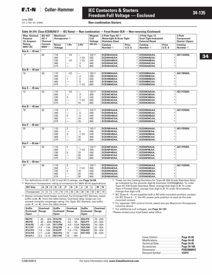
June 2005
CA08102001E For more information visit: www.EatonElectrical.com
34-135IEC Contactors & Starters
34
Freedom Full Voltage — EnclosedNon-combination StartersVol. 2, Ref. No. [0399]
Table 34-214. Class ECE09/AE17 — IEC Rated — Non-combination — Fixed Heater OLR — Non-reversing (Continued)
� For definitions of AC-1, AC-2 and AC-3 ratings, see Page 34-99.� Maximum horsepower rating of contactors for 380V 50 Hz applications:
� Starter includes fixed heater overload. For Enclosed IEC Starters, select suffix code -R_ from the table below. Overload relay range can not exceed contactor amperage rating. For Open IEC Starters, use suffix code -F_ or -K_ from the table below.
� These are the Catalog Numbers for Type 4X 304-Grade Stainless Steel, as indicated by the seventh digit 4. Example: ECE09A4AAA. To order Type 4X 316-Grade Stainless Steel, change that digit to 9. To order Type 4 Painted Steel, change that digit to 3. To order Nonmetallic, change that digit to 5.
� IEC Sizes A – N are supplied with a NO side mounted auxiliary contact. On IEC Sizes A – C, the 4th power pole position is used as the side mounted contact.
� For separate 120V control circuit, select size per Maximum Horsepower columns above.
� For additional coil voltages, see Page 34-125.*Please contact your local Eaton sales office.
Max. General PurposeUL AmpereRating600V AC
IEC 947AC-1ThermalCurrent600V �
MaximumHorsepower �
MagnetCoilVoltage(60 Hz) �
3-Pole Type 4X �
Watertight & Dust-TightStainless Steel
3-Pole Type 12Dust-Tight IndustrialExternal Reset
3-Pole Component Starter (Open)
MotorVoltage
1-Ph 3-Ph CatalogNumber �
PriceU.S. $
CatalogNumber �
PriceU.S. $
CatalogNumber �
Size A — 45 mm �
7 20 115200230460575
1/4— 1/2
——
—1-1/21-1/235
120 �208240480600
ECE09A4AAA_ECE09A4EAA_ECE09A4BAA_ECE09A4CAA_ECE09A4DAA_
*****
ECE09A8AAA_ECE09A8EAA_ECE09A8BAA_ECE09A8CAA_ECE09A8DAA_
*****
AE17ANS0_
Size B — 45 mm �
10 20 115200230460575
1/2—1——
—2257-1/2
120 �208240480600
ECE09B4AAA_ECE09B4EAA_ECE09B4BAA_ECE09B4CAA_ECE09B4DAA_
*****
ECE09B8AAA_ECE09B8EAA_ECE09B8BAA_ECE09B8CAA_ECE09B8DAA_
*****
AE17BNS0_
Size C — 45 mm �
12 20 115200230460575
1/2—2——
—337-1/2
10
120 �208240480600
ECE09C4AAA_ECE09C4EAA_ECE09C4BAA_ECE09C4CAA_ECE09C4DAA_
*****
ECE09C8AAA_ECE09C8EAA_ECE09C8BAA_ECE09C8CAA_ECE09C8DAA_
*****
AE17CNS0_
Size D — 45 mm �
18 32 115200230460575
1—3——
—55
1015
120 �208240480600
ECE09D4AAA_ECE09D4EAA_ECE09D4BAA_ECE09D4CAA_ECE09D4DAA_
*****
ECE09D8AAA_ECE09D8EAA_ECE09D8BAA_ECE09D8CAA_ECE09D8DAA_
*****
AE17DNS0_
Size E — 45 mm �
25 32 115200230460575
2—3——
—57-1/2
1520
120 �208240480600
ECE09E4AAA_ECE09E4EAA_ECE09E4BAA_ECE09E4CAA_ECE09E4DAA_
*****
ECE09E8AAA_ECE09E8EAA_ECE09E8BAA_ECE09E8CAA_ECE09E8DAA_
*****
AE17ENS0_
Size F — 45 mm �
32 32 115200230460575
2—5——
—7-1/2
102025
120 �208240480600
ECE09F4AAA_ECE09F4EAA_ECE09F4BAA_ECE09F4CAA_ECE09F4DAA_
*****
ECE09F8AAA_ECE09F8EAA_ECE09F8BAA_ECE09F8CAA_ECE09F8DAA_
*****
AE17FNS0_
Size G — 65 mm �
37 50 115200230460575
3—5——
—7-1/2
102530
120 �208240480600
ECE09G4AAA_ECE09G4EAA_ECE09G4BAA_ECE09G4CAA_ECE09G4DAA_
*****
ECE09G8AAA_ECE09G8EAA_ECE09G8BAA_ECE09G8CAA_ECE09G8DAA_
*****
AE17GNS0_
IEC Size A B C D E F G H J K L M N
Horsepower 3 5 5 10 10 15 20 25 30 40 50 60 75
SuffixEnclosed/Open
OverloadRange
SuffixEnclosed/Open
OverloadRange
SuffixEnclosed/Open
OverloadRange
R8/FCR9/FDR10/FER11/FFR12/FGR13/FHR14/FJ
.25 – .40A
.40 – .63A
.63 – 1.0A1.0 – 1.4A1.8 – 1.8A1.7 – 2.4A2.2 – 3.1A
R15/FKR16/FLR17/FMR18/FNR19/FPR20/FQR21/FR
2.8 – 4.0A3.5 – 5A4.5 – 6.5A6.5 – 8.5A7.5 – 11A
10.5 – 14A13.5 – 19A
R22/FSR23/FTR24/KAR25/KBR26/KCR27/KD
18 – 24A24 – 32A18 – 25A22 – 32A29 – 42A36 – 52A
Cover Control . . . . . . . . . . . . . . . . . . . . Page 33-99Modifications . . . . . . . . . . . . . . . . . . . . Page 34-49Technical Data . . . . . . . . . . . . . . . . . . . Page 34-95Accessories . . . . . . . . . . . . . . . . . . . . . Page 34-100Dimensions . . . . . . . . . . . . . . . . . . . . . . PG03300001EDiscount Symbol . . . . . . . . . . . . . . . . . 1CD1C
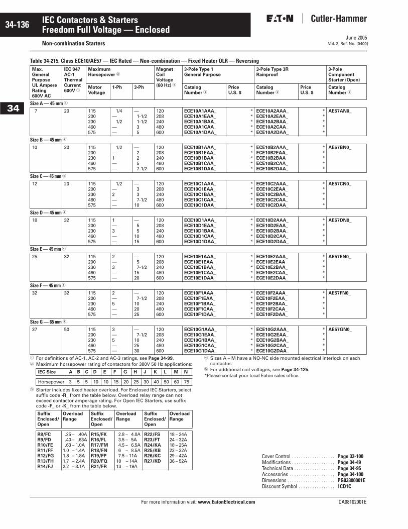
June 2005
34-136
For more information visit: www.EatonElectrical.com CA08102001E
IEC Contactors & Starters
34
Freedom Full Voltage — EnclosedNon-combination Starters Vol. 2, Ref. No. [0400]
Table 34-215. Class ECE10/AE57 — IEC Rated — Non-combination — Fixed Heater OLR — Reversing
� For definitions of AC-1, AC-2 and AC-3 ratings, see Page 34-99.� Maximum horsepower rating of contactors for 380V 50 Hz applications:
� Starter includes fixed heater overload. For Enclosed IEC Starters, select suffix code -R_ from the table below. Overload relay range can not exceed contactor amperage rating. For Open IEC Starters, use suffix code -F_ or -K_ from the table below.
� Sizes A – M have a NO-NC side mounted electrical interlock on each contactor.
� For additional coil voltages, see Page 34-125.*Please contact your local Eaton sales office.
Max. General PurposeUL AmpereRating600V AC
IEC 947AC-1ThermalCurrent600V �
MaximumHorsepower �
MagnetCoilVoltage(60 Hz) �
3-Pole Type 1General Purpose
3-Pole Type 3RRainproof
3-Pole Component Starter (Open)
MotorVoltage
1-Ph 3-Ph Catalog Number �
PriceU.S. $
Catalog Number �
PriceU.S. $
CatalogNumber �
Size A — 45 mm �
7 20 115200230460575
1/4— 1/2
——
—1-1/21-1/235
120 208240480600
ECE10A1AAA_ECE10A1EAA_ECE10A1BAA_ECE10A1CAA_ECE10A1DAA_
*****
ECE10A2AAA_ECE10A2EAA_ECE10A2BAA_ECE10A2CAA_ECE10A2DAA_
*****
AE57AN0_
Size B — 45 mm �
10 20 115200230460575
1/2—1——
—2257-1/2
120 208240480600
ECE10B1AAA_ECE10B1EAA_ECE10B1BAA_ECE10B1CAA_ECE10B1DAA_
*****
ECE10B2AAA_ECE10B2EAA_ECE10B2BAA_ECE10B2CAA_ECE10B2DAA_
*****
AE57BN0_
Size C — 45 mm � 12 20 115
200230460575
1/2—2——
—337-1/2
10
120 208240480600
ECE10C1AAA_ECE10C1EAA_ECE10C1BAA_ECE10C1CAA_ECE10C1DAA_
*****
ECE10C2AAA_ECE10C2EAA_ECE10C2BAA_ECE10C2CAA_ECE10C2DAA_
*****
AE57CN0_
Size D — 45 mm �
18 32 115200230460575
1—3——
—55
1015
120 208240480600
ECE10D1AAA_ECE10D1EAA_ECE10D1BAA_ECE10D1CAA_ECE10D1DAA_
*****
ECE10D2AAA_ECE10D2EAA_ECE10D2BAA_ECE10D2CAA_ECE10D2DAA_
*****
AE57DN0_
Size E — 45 mm �
25 32 115200230460575
2—3——
—57-1/2
1520
120 208240480600
ECE10E1AAA_ECE10E1EAA_ECE10E1BAA_ECE10E1CAA_ECE10E1DAA_
*****
ECE10E2AAA_ECE10E2EAA_ECE10E2BAA_ECE10E2CAA_ECE10E2DAA_
*****
AE57EN0_
Size F — 45 mm �
32 32 115200230460575
2—5——
—7-1/2
102025
120 208240480600
ECE10F1AAA_ECE10F1EAA_ECE10F1BAA_ECE10F1CAA_ECE10F1DAA_
*****
ECE10F2AAA_ECE10F2EAA_ECE10F2BAA_ECE10F2CAA_ECE10F2DAA_
*****
AE57FN0_
Size G — 65 mm �
37 50 115200230460575
3—5——
—7-1/2
102530
120 208240480600
ECE10G1AAA_ECE10G1EAA_ECE10G1BAA_ECE10G1CAA_ECE10G1DAA_
*****
ECE10G2AAA_ECE10G2EAA_ECE10G2BAA_ECE10G2CAA_ECE10G2DAA_
*****
AE57GN0_
IEC Size A B C D E F G H J K L M N
Horsepower 3 5 5 10 10 15 20 25 30 40 50 60 75
SuffixEnclosed/Open
OverloadRange
SuffixEnclosed/Open
OverloadRange
SuffixEnclosed/Open
OverloadRange
R8/FCR9/FDR10/FER11/FFR12/FGR13/FHR14/FJ
.25 – .40A
.40 – .63A
.63 – 1.0A1.0 – 1.4A1.8 – 1.8A1.7 – 2.4A2.2 – 3.1A
R15/FKR16/FLR17/FMR18/FNR19/FPR20/FQR21/FR
2.8 – 4.0A3.5 – 5A4.5 – 6.5A6.5 – 8.5A7.5 – 11A
10.5 – 14A13.5 – 19A
R22/FSR23/FTR24/KAR25/KBR26/KCR27/KD
18 – 24A24 – 32A18 – 25A22 – 32A29 – 42A36 – 52A
Cover Control . . . . . . . . . . . . . . . . . . . Page 33-100Modifications . . . . . . . . . . . . . . . . . . . Page 34-49Technical Data . . . . . . . . . . . . . . . . . . Page 34-95Accessories . . . . . . . . . . . . . . . . . . . . Page 34-100Dimensions . . . . . . . . . . . . . . . . . . . . . PG03300001EDiscount Symbol . . . . . . . . . . . . . . . . 1CD1C
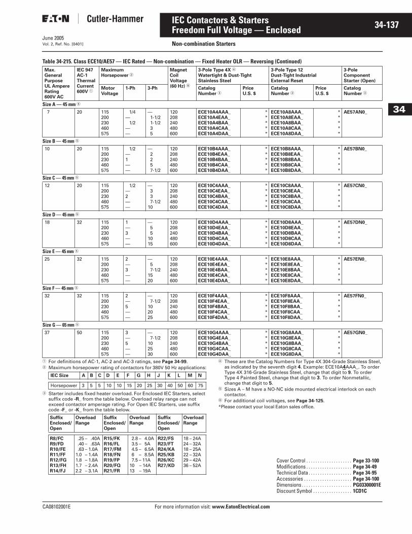
June 2005
CA08102001E For more information visit: www.EatonElectrical.com
34-137IEC Contactors & Starters
34
Freedom Full Voltage — EnclosedNon-combination StartersVol. 2, Ref. No. [0401]
Table 34-215. Class ECE10/AE57 — IEC Rated — Non-combination — Fixed Heater OLR — Reversing (Continued)
� For definitions of AC-1, AC-2 and AC-3 ratings, see Page 34-99.� Maximum horsepower rating of contactors for 380V 50 Hz applications:
� Starter includes fixed heater overload. For Enclosed IEC Starters, select suffix code -R_ from the table below. Overload relay range can not exceed contactor amperage rating. For Open IEC Starters, use suffix code -F_ or -K_ from the table below.
� These are the Catalog Numbers for Type 4X 304-Grade Stainless Steel, as indicated by the seventh digit 4. Example: ECE10A4AAA_. To order Type 4X 316-Grade Stainless Steel, change that digit to 9. To order Type 4 Painted Steel, change that digit to 3. To order Nonmetallic, change that digit to 5.
� Sizes A – M have a NO-NC side mounted electrical interlock on each contactor.
� For additional coil voltages, see Page 34-125.*Please contact your local Eaton sales office.
Max. General PurposeUL AmpereRating600V AC
IEC 947AC-1ThermalCurrent600V �
MaximumHorsepower �
MagnetCoilVoltage(60 Hz) �
3-Pole Type 4X �
Watertight & Dust-TightStainless Steel
3-Pole Type 12Dust-Tight IndustrialExternal Reset
3-Pole Component Starter (Open)
MotorVoltage
1-Ph 3-Ph Catalog Number �
PriceU.S. $
Catalog Number �
PriceU.S. $
CatalogNumber �
Size A — 45 mm �
7 20 115200230460575
1/4— 1/2
——
—1-1/21-1/235
120 208240480600
ECE10A4AAA_ECE10A4EAA_ECE10A4BAA_ECE10A4CAA_ECE10A4DAA_
*****
ECE10A8AAA_ECE10A8EAA_ECE10A8BAA_ECE10A8CAA_ECE10A8DAA_
*****
AE57AN0_
Size B — 45 mm �
10 20 115200230460575
1/2—1——
—2257-1/2
120 208240480600
ECE10B4AAA_ECE10B4EAA_ECE10B4BAA_ECE10B4CAA_ECE10B4DAA_
*****
ECE10B8AAA_ECE10B8EAA_ECE10B8BAA_ECE10B8CAA_ECE10B8DAA_
*****
AE57BN0_
Size C — 45 mm � 12 20 115
200230460575
1/2—2——
—337-1/2
10
120 208240480600
ECE10C4AAA_ECE10C4EAA_ECE10C4BAA_ECE10C4CAA_ECE10C4DAA_
*****
ECE10C8AAA_ECE10C8EAA_ECE10C8BAA_ECE10C8CAA_ECE10C8DAA_
*****
AE57CN0_
Size D — 45 mm �
18 32 115200230460575
1—3——
—55
1015
120 208240480600
ECE10D4AAA_ECE10D4EAA_ECE10D4BAA_ECE10D4CAA_ECE10D4DAA_
*****
ECE10D8AAA_ECE10D8EAA_ECE10D8BAA_ECE10D8CAA_ECE10D8DAA_
*****
AE57DN0_
Size E — 45 mm �
25 32 115200230460575
2—3——
—57-1/2
1520
120 208240480600
ECE10E4AAA_ECE10E4EAA_ECE10E4BAA_ECE10E4CAA_ECE10E4DAA_
*****
ECE10E8AAA_ECE10E8EAA_ECE10E8BAA_ECE10E8CAA_ECE10E8DAA_
*****
AE57EN0_
Size F — 45 mm �
32 32 115200230460575
2—5——
—7-1/2
102025
120 208240480600
ECE10F4AAA_ECE10F4EAA_ECE10F4BAA_ECE10F4CAA_ECE10F4DAA_
*****
ECE10F8AAA_ECE10F8EAA_ECE10F8BAA_ECE10F8CAA_ECE10F8DAA_
*****
AE57FN0_
Size G — 65 mm �
37 50 115200230460575
3—5——
—7-1/2
102530
120 208240480600
ECE10G4AAA_ECE10G4EAA_ECE10G4BAA_ECE10G4CAA_ECE10G4DAA_
*****
ECE10G8AAA_ECE10G8EAA_ECE10G8BAA_ECE10G8CAA_ECE10G8DAA_
*****
AE57GN0_
IEC Size A B C D E F G H J K L M N
Horsepower 3 5 5 10 10 15 20 25 30 40 50 60 75
SuffixEnclosed/Open
OverloadRange
SuffixEnclosed/Open
OverloadRange
SuffixEnclosed/Open
OverloadRange
R8/FCR9/FDR10/FER11/FFR12/FGR13/FHR14/FJ
.25 – .40A
.40 – .63A
.63 – 1.0A1.0 – 1.4A1.8 – 1.8A1.7 – 2.4A2.2 – 3.1A
R15/FKR16/FLR17/FMR18/FNR19/FPR20/FQR21/FR
2.8 – 4.0A3.5 – 5A4.5 – 6.5A6.5 – 8.5A7.5 – 11A
10.5 – 14A13.5 – 19A
R22/FSR23/FTR24/KAR25/KBR26/KCR27/KD
18 – 24A24 – 32A18 – 25A22 – 32A29 – 42A36 – 52A
Cover Control . . . . . . . . . . . . . . . . . . . . Page 33-100Modifications . . . . . . . . . . . . . . . . . . . . Page 34-49Technical Data . . . . . . . . . . . . . . . . . . . Page 34-95Accessories . . . . . . . . . . . . . . . . . . . . . Page 34-100Dimensions . . . . . . . . . . . . . . . . . . . . . . PG03300001EDiscount Symbol . . . . . . . . . . . . . . . . . 1CD1C
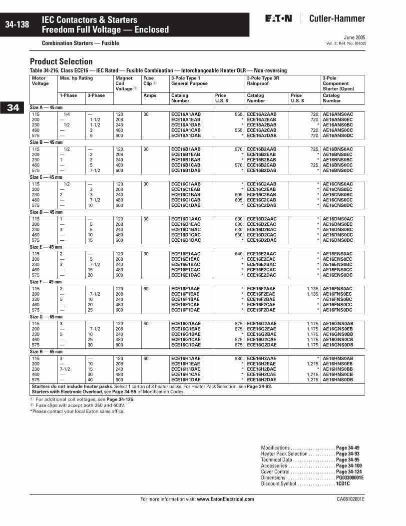
June 2005
34-138
For more information visit: www.EatonElectrical.com CA08102001E
IEC Contactors & Starters
34
Freedom Full Voltage — EnclosedCombination Starters — Fusible Vol. 2, Ref. No. [0402]
Product SelectionTable 34-216. Class ECE16 — IEC Rated — Fusible Combination — Interchangeable Heater OLR — Non-reversing
� For additional coil voltages, see Page 34-125.� Fuse clips will accept both 250 and 600V.*Please contact your local Eaton sales office.
MotorVoltage
Max. hp Rating Magnet Coil Voltage �
FuseClip �
3-Pole Type 1 General Purpose
3-Pole Type 3RRainproof
3-Pole Component Starter (Open)
1-Phase 3-Phase Amps CatalogNumber
PriceU.S. $
CatalogNumber
PriceU.S. $
CatalogNumber
Size A — 45 mm115200230460575
1/4— 1/2
——
—1-1/21-1/235
120208240480600
30 ECE16A1AABECE16A1EABECE16A1BABECE16A1CABECE16A1DAB
555.**
555.*
ECE16A2AABECE16A2EABECE16A2BABECE16A2CABECE16A2DAB
720.720.
*720.720.
AE16ANS0ACAE16ANS0ECAE16ANS0BCAE16ANS0CCAE16ANS0DC
Size B — 45 mm115200230460575
1/2—1——
—2257-1/2
120208240480600
30 ECE16B1AABECE16B1EABECE16B1BABECE16B1CABECE16B1DAB
570.**
570.*
ECE16B2AABECE16B2EABECE16B2BABECE16B2CABECE16B2DAB
725.**
725.*
AE16BNS0ACAE16BNS0ECAE16BNS0BCAE16BNS0CCAE16BNS0DC
Size C — 45 mm115200230460575
1/2—2——
—337-1/2
10
120208240480600
30 ECE16C1AABECE16C1EABECE16C1BABECE16C1CABECE16C1DAB
**
605.605.
*
ECE16C2AABECE16C2EABECE16C2BABECE16C2CABECE16C2DAB
*****
AE16CNS0ACAE16CNS0ECAE16CNS0BCAE16CNS0CCAE16CNS0DC
Size D — 45 mm115200230460575
1—3——
—55
1015
120208240480600
30 ECE16D1AACECE16D1EACECE16D1BACECE16D1CACECE16D1DAC
630.630.630.630.
*
ECE16D2AACECE16D2EACECE16D2BACECE16D2CACECE16D2DAC
*****
AE16DNS0ACAE16DNS0ECAE16DNS0BCAE16DNS0CCAE16DNS0DC
Size E — 45 mm115200230460575
2—3——
—57-1/2
1520
120208240480600
30 ECE16E1AACECE16E1EACECE16E1BACECE16E1CACECE16E1DAC
640.****
ECE16E2AACECE16E2EACECE16E2BACECE16E2CACECE16E2DAC
*****
AE16ENS0ACAE16ENS0ECAE16ENS0BCAE16ENS0CCAE16ENS0DC
Size F — 45 mm115200230460575
2—5——
—7-1/2
102025
120208240480600
60 ECE16F1AAEECE16F1EAEECE16F1BAEECE16F1CAEECE16F1DAE
*****
ECE16F2AAEECE16F2EAEECE16F2BAEECE16F2CAEECE16F2DAE
1,135.1,135.
***
AE16FNS0ACAE16FNS0ECAE16FNS0BCAE16FNS0CCAE16FNS0DC
Size G — 65 mm115200230460575
3—5——
—7-1/2
102530
120208240480600
60 ECE16G1AAEECE16G1EAEECE16G1BAEECE16G1CAEECE16G1DAE
875.875.
*875.875.
ECE16G2AAEECE16G2EAEECE16G2BAEECE16G2CAEECE16G2DAE
1,175.1,175.1,175.1,175.1,175.
AE16GNS0ABAE16GNS0EBAE16GNS0BBAE16GNS0CBAE16GNS0DB
Size H — 65 mm115200230460575
3—7-1/2——
—10153040
120208240480600
60 ECE16H1AAEECE16H1EAEECE16H1BAEECE16H1CAEECE16H1DAE
930.****
ECE16H2AAEECE16H2EAEECE16H2BAEECE16H2CAEECE16H2DAE
*1,215.
*1,215.1,215.
AE16HNS0ABAE16HNS0EBAE16HNS0BBAE16HNS0CBAE16HNS0DB
Starters do not include heater packs. Select 1 carton of 3 heater packs. For Heater Pack Selection, see Page 34-93.Starters with Electronic Overload, see Page 34-55 of Modification Codes.
Modifications . . . . . . . . . . . . . . . . . . . . Page 34-49Heater Pack Selection . . . . . . . . . . . . Page 34-93Technical Data . . . . . . . . . . . . . . . . . . . Page 34-95Accessories . . . . . . . . . . . . . . . . . . . . . Page 34-100Cover Control . . . . . . . . . . . . . . . . . . . . Page 34-124Dimensions . . . . . . . . . . . . . . . . . . . . . . PG03300001EDiscount Symbol . . . . . . . . . . . . . . . . . 1CD1C
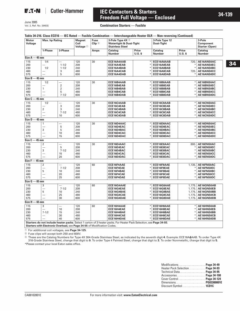
June 2005
CA08102001E For more information visit: www.EatonElectrical.com
34-139IEC Contactors & Starters
34
Freedom Full Voltage — EnclosedCombination Starters — Fusible Vol. 2, Ref. No. [0403]
Table 34-216. Class ECE16 — IEC Rated — Fusible Combination — Interchangeable Heater OLR — Non-reversing (Continued)
� For additional coil voltages, see Page 34-125.� Fuse clips will accept both 250 and 600V.� These are the Catalog Numbers for Type 4X 304-Grade Stainless Steel, as indicated by the seventh digit 4. Example: ECE16A4AAB. To order Type 4X
316-Grade Stainless Steel, change that digit to 9. To order Type 4 Painted Steel, change that digit to 3. To order Nonmetallic, change that digit to 5.*Please contact your local Eaton sales office.
MotorVoltage
Max. hp Rating Magnet Coil Voltage �
FuseClip �
3-Pole Type 4X �
Watertight & Dust-TightStainless Steel
3-Pole Type 12 Dust-Tight
3-Pole Component Starter (Open)
1-Phase 3-Phase Amps CatalogNumber
PriceU.S. $
CatalogNumber
PriceU.S. $
CatalogNumber
Size A — 45 mm115200230460575
1/4— 1/2
——
—1-1/21-1/235
120208240480600
30 ECE16A4AABECE16A4EABECE16A4BABECE16A4CABECE16A4DAB
*****
ECE16A8AABECE16A8EABECE16A8BABECE16A8CABECE16A8DAB
720.**
720.*
AE16ANS0ACAE16ANS0ECAE16ANS0BCAE16ANS0CCAE16ANS0DC
Size B — 45 mm115200230460575
1/2—1——
—2257-1/2
120208240480600
30 ECE16B4AABECE16B4EABECE16B4BABECE16B4CABECE16B4DAB
*****
ECE16B8AABECE16B8EABECE16B8BABECE16B8CABECE16B8DAB
*****
AE16BNS0ACAE16BNS0ECAE16BNS0BCAE16BNS0CCAE16BNS0DC
Size C — 45 mm115200230460575
1/2—2——
—337-1/2
10
120208240480600
30 ECE16C4AABECE16C4EABECE16C4BABECE16C4CABECE16C4DAB
*****
ECE16C8AABECE16C8EABECE16C8BABECE16C8CABECE16C8DAB
*****
AE16CNS0ACAE16CNS0ECAE16CNS0BCAE16CNS0CCAE16CNS0DC
Size D — 45 mm115200230460575
1—3——
—55
1015
120208240480600
30 ECE16D4AACECE16D4EACECE16D4BACECE16D4CACECE16D4DAC
*****
ECE16D8AACECE16D8EACECE16D8BACECE16D8CACECE16D8DAC
*****
AE16DNS0ACAE16DNS0ECAE16DNS0BCAE16DNS0CCAE16DNS0DC
Size E — 45 mm115200230460575
2—3——
—57-1/2
1520
120208240480600
30 ECE16E4AACECE16E4EACECE16E4BACECE16E4CACECE16E4DAC
*****
ECE16E8AACECE16E8EACECE16E8BACECE16E8CACECE16E8DAC
800.****
AE16ENS0ACAE16ENS0ECAE16ENS0BCAE16ENS0CCAE16ENS0DC
Size F — 45 mm115200230460575
2—5——
—7-1/2
102025
120208240480600
60 ECE16F4AAEECE16F4EAEECE16F4BAEECE16F4CAEECE16F4DAE
*****
ECE16F8AAEECE16F8EAEECE16F8BAEECE16F8CAEECE16F8DAE
1,135.****
AE16FNS0ACAE16FNS0ECAE16FNS0BCAE16FNS0CCAE16FNS0DC
Size G — 65 mm115200230460575
3—5——
—7-1/2
102530
120208240480600
60 ECE16G4AAEECE16G4EAEECE16G4BAEECE16G4CAEECE16G4DAE
*****
ECE16G8AAEECE16G8EAEECE16G8BAEECE16G8CAEECE16G8DAE
1,175.1,175.1,175.1,175.1,175.
AE16GNS0ABAE16GNS0EBAE16GNS0BBAE16GNS0CBAE16GNS0DB
Size H — 65 mm115200230460575
3—7-1/2——
—10153040
120208240480600
60 ECE16H4AAEECE16H4EAEECE16H4BAEECE16H4CAEECE16H4DAE
*****
ECE16H8AAEECE16H8EAEECE16H8BAEECE16H8CAEECE16H8DAE
*****
AE16HNS0ABAE16HNS0EBAE16HNS0BBAE16HNS0CBAE16HNS0DB
Starters do not include heater packs. Select 1 carton of 3 heater packs. For Heater Pack Selection, see Page 34-93.Starters with Electronic Overload, see Page 34-55 of Modification Codes.
Modifications. . . . . . . . . . . . . . . . . . . . Page 34-49Heater Pack Selection . . . . . . . . . . . . Page 34-93Technical Data. . . . . . . . . . . . . . . . . . . Page 34-95Accessories . . . . . . . . . . . . . . . . . . . . . Page 34-100Cover Control . . . . . . . . . . . . . . . . . . . . Page 34-124Dimensions. . . . . . . . . . . . . . . . . . . . . . PG03300001EDiscount Symbol . . . . . . . . . . . . . . . . . 1CD1C
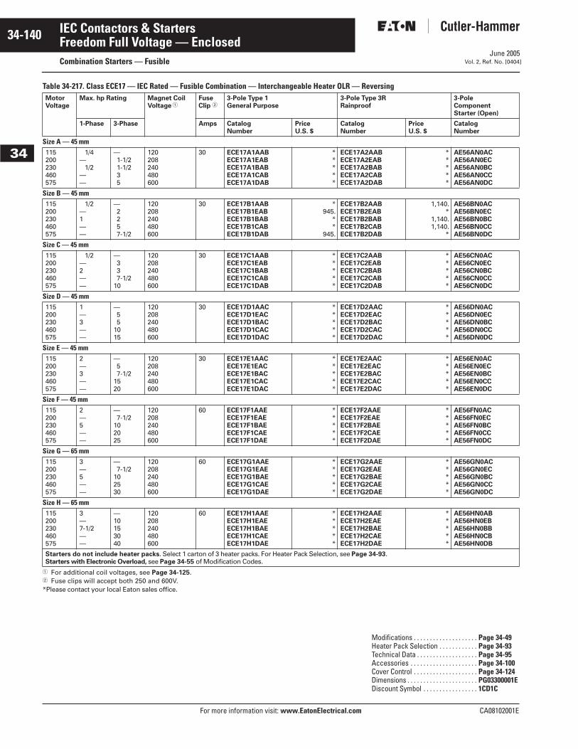
June 2005
34-140
For more information visit: www.EatonElectrical.com CA08102001E
IEC Contactors & Starters
34
Freedom Full Voltage — EnclosedCombination Starters — Fusible Vol. 2, Ref. No. [0404]
Table 34-217. Class ECE17 — IEC Rated — Fusible Combination — Interchangeable Heater OLR — Reversing
� For additional coil voltages, see Page 34-125.� Fuse clips will accept both 250 and 600V.*Please contact your local Eaton sales office.
MotorVoltage
Max. hp Rating Magnet Coil Voltage �
FuseClip �
3-Pole Type 1 General Purpose
3-Pole Type 3RRainproof
3-Pole Component Starter (Open)
1-Phase 3-Phase Amps CatalogNumber
PriceU.S. $
CatalogNumber
PriceU.S. $
CatalogNumber
Size A — 45 mm115200230460575
1/4— 1/2
——
—1-1/21-1/235
120208240480600
30 ECE17A1AABECE17A1EABECE17A1BABECE17A1CABECE17A1DAB
*****
ECE17A2AABECE17A2EABECE17A2BABECE17A2CABECE17A2DAB
*****
AE56AN0ACAE56AN0ECAE56AN0BCAE56AN0CCAE56AN0DC
Size B — 45 mm115200230460575
1/2—1——
—2257-1/2
120208240480600
30 ECE17B1AABECE17B1EABECE17B1BABECE17B1CABECE17B1DAB
*945.
**
945.
ECE17B2AABECE17B2EABECE17B2BABECE17B2CABECE17B2DAB
1,140.*
1,140.1,140.
*
AE56BN0ACAE56BN0ECAE56BN0BCAE56BN0CCAE56BN0DC
Size C — 45 mm115200230460575
1/2—2——
—337-1/2
10
120208240480600
30 ECE17C1AABECE17C1EABECE17C1BABECE17C1CABECE17C1DAB
*****
ECE17C2AABECE17C2EABECE17C2BABECE17C2CABECE17C2DAB
*****
AE56CN0ACAE56CN0ECAE56CN0BCAE56CN0CCAE56CN0DC
Size D — 45 mm115200230460575
1—3——
—55
1015
120208240480600
30 ECE17D1AACECE17D1EACECE17D1BACECE17D1CACECE17D1DAC
*****
ECE17D2AACECE17D2EACECE17D2BACECE17D2CACECE17D2DAC
*****
AE56DN0ACAE56DN0ECAE56DN0BCAE56DN0CCAE56DN0DC
Size E — 45 mm115200230460575
2—3——
—57-1/2
1520
120208240480600
30 ECE17E1AACECE17E1EACECE17E1BACECE17E1CACECE17E1DAC
*****
ECE17E2AACECE17E2EACECE17E2BACECE17E2CACECE17E2DAC
*****
AE56EN0ACAE56EN0ECAE56EN0BCAE56EN0CCAE56EN0DC
Size F — 45 mm115200230460575
2—5——
—7-1/2
102025
120208240480600
60 ECE17F1AAEECE17F1EAEECE17F1BAEECE17F1CAEECE17F1DAE
*****
ECE17F2AAEECE17F2EAEECE17F2BAEECE17F2CAEECE17F2DAE
*****
AE56FN0ACAE56FN0ECAE56FN0BCAE56FN0CCAE56FN0DC
Size G — 65 mm115200230460575
3—5——
—7-1/2
102530
120208240480600
60 ECE17G1AAEECE17G1EAEECE17G1BAEECE17G1CAEECE17G1DAE
*****
ECE17G2AAEECE17G2EAEECE17G2BAEECE17G2CAEECE17G2DAE
*****
AE56GN0ACAE56GN0ECAE56GN0BCAE56GN0CCAE56GN0DC
Size H — 65 mm115200230460575
3—7-1/2——
—10153040
120208240480600
60 ECE17H1AAEECE17H1EAEECE17H1BAEECE17H1CAEECE17H1DAE
*****
ECE17H2AAEECE17H2EAEECE17H2BAEECE17H2CAEECE17H2DAE
*****
AE56HN0ABAE56HN0EBAE56HN0BBAE56HN0CBAE56HN0DB
Starters do not include heater packs. Select 1 carton of 3 heater packs. For Heater Pack Selection, see Page 34-93.Starters with Electronic Overload, see Page 34-55 of Modification Codes.
Modifications . . . . . . . . . . . . . . . . . . . . Page 34-49Heater Pack Selection . . . . . . . . . . . . Page 34-93Technical Data . . . . . . . . . . . . . . . . . . . Page 34-95Accessories . . . . . . . . . . . . . . . . . . . . . Page 34-100Cover Control . . . . . . . . . . . . . . . . . . . . Page 34-124Dimensions . . . . . . . . . . . . . . . . . . . . . . PG03300001EDiscount Symbol . . . . . . . . . . . . . . . . . 1CD1C
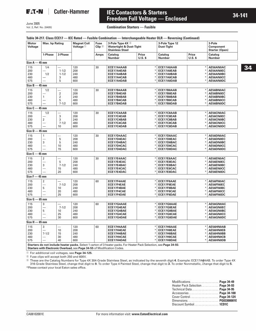
June 2005
CA08102001E For more information visit: www.EatonElectrical.com
34-141IEC Contactors & Starters
34
Freedom Full Voltage — EnclosedCombination Starters — FusibleVol. 2, Ref. No. [0405]
Table 34-217. Class ECE17 — IEC Rated — Fusible Combination — Interchangeable Heater OLR — Reversing (Continued)
� For additional coil voltages, see Page 34-125.� Fuse clips will accept both 250 and 600V.� These are the Catalog Numbers for Type 4X 304-Grade Stainless Steel, as indicated by the seventh digit 4. Example: ECE17A4AAB. To order Type 4X
316-Grade Stainless Steel, change that digit to 9. To order Type 4 Painted Steel, change that digit to 3. To order Nonmetallic, change that digit to 5.*Please contact your local Eaton sales office.
MotorVoltage
Max. hp Rating Magnet Coil Voltage �
FuseClip �
3-Pole Type 4X �
Watertight & Dust-TightStainless Steel
3-Pole Type 12 Dust-Tight
3-Pole Component Starter (Open)
1-Phase 3-Phase Amps CatalogNumber
PriceU.S. $
CatalogNumber
PriceU.S. $
CatalogNumber
Size A — 45 mm115200230460575
1/4— 1/2
——
—1-1/21-1/235
120208240480600
30 ECE17A4AABECE17A4EABECE17A4BABECE17A4CABECE17A4DAB
*****
ECE17A8AABECE17A8EABECE17A8BABECE17A8CABECE17A8DAB
*****
AE56AN0ACAE56AN0ECAE56AN0BCAE56AN0CCAE56AN0DC
Size B — 45 mm115200230460575
1/2—1——
—2257-1/2
120208240480600
30 ECE17B4AABECE17B4EABECE17B4BABECE17B4CABECE17B4DAB
*****
ECE17B8AABECE17B8EABECE17B8BABECE17B8CABECE17B8DAB
*****
AE56BN0ACAE56BN0ECAE56BN0BCAE56BN0CCAE56BN0DC
Size C — 45 mm115200230460575
1/2—2——
—337-1/2
10
120208240480600
30 ECE17C4AABECE17C4EABECE17C4BABECE17C4CABECE17C4DAB
*****
ECE17C8AABECE17C8EABECE17C8BABECE17C8CABECE17C8DAB
*****
AE56CN0ACAE56CN0ECAE56CN0BCAE56CN0CCAE56CN0DC
Size D — 45 mm115200230460575
1—3——
—55
1015
120208240480600
30 ECE17D4AACECE17D4EACECE17D4BACECE17D4CACECE17D4DAC
*****
ECE17D8AACECE17D8EACECE17D8BACECE17D8CACECE17D8DAC
*****
AE56DN0ACAE56DN0ECAE56DN0BCAE56DN0CCAE56DN0DC
Size E — 45 mm115200230460575
2—3——
—57-1/2
1520
120208240480600
30 ECE17E4AACECE17E4EACECE17E4BACECE17E4CACECE17E4DAC
*****
ECE17E8AACECE17E8EACECE17E8BACECE17E8CACECE17E8DAC
*****
AE56EN0ACAE56EN0ECAE56EN0BCAE56EN0CCAE56EN0DC
Size F — 45 mm115200230460575
2—5——
—7-1/2
102025
120208240480600
60 ECE17F4AAEECE17F4EAEECE17F4BAEECE17F4CAEECE17F4DAE
*****
ECE17F8AAEECE17F8EAEECE17F8BAEECE17F8CAEECE17F8DAE
*****
AE56FN0ACAE56FN0ECAE56FN0BCAE56FN0CCAE56FN0DC
Size G — 65 mm115200230460575
3—5——
—7-1/2
102530
120208240480600
60 ECE17G4AAEECE17G4EAEECE17G4BAEECE17G4CAEECE17G4DAE
*****
ECE17G8AAEECE17G8EAEECE17G8BAEECE17G8CAEECE17G8DAE
*****
AE56GN0ACAE56GN0ECAE56GN0BCAE56GN0CCAE56GN0DC
Size H — 65 mm115200230460575
3—7-1/2——
—10153040
120208240480600
60 ECE17H4AAEECE17H4EAEECE17H4BAEECE17H4CAEECE17H4DAE
*****
ECE17H8AAEECE17H8EAEECE17H8BAEECE17H8CAEECE17H8DAE
*****
AE56HN0ABAE56HN0EBAE56HN0BBAE56HN0CBAE56HN0DB
Starters do not include heater packs. Select 1 carton of 3 heater packs. For Heater Pack Selection, see Page 34-93.Starters with Electronic Overload, see Page 34-55 of Modification Codes.
Modifications. . . . . . . . . . . . . . . . . . . . Page 34-49Heater Pack Selection . . . . . . . . . . . . Page 34-93Technical Data. . . . . . . . . . . . . . . . . . . Page 34-95Accessories . . . . . . . . . . . . . . . . . . . . . Page 34-100Cover Control . . . . . . . . . . . . . . . . . . . . Page 34-124Dimensions. . . . . . . . . . . . . . . . . . . . . . PG03300001EDiscount Symbol . . . . . . . . . . . . . . . . . 1CD1C

June 2005
34-142
For more information visit: www.EatonElectrical.com CA08102001E
IEC Contactors & Starters
34
Freedom Full Voltage — EnclosedCombination Starters — Fusible Vol. 2, Ref. No. [0406]
Table 34-218. Class ECE19 — IEC Rated — Fusible Combination — Fixed Heater OLR — Non-reversing
� For additional coil voltages, refer to Page 34-125.� Starter includes fixed heater overload. For Enclosed IEC Starters, select
suffix code -R_ from the table below. Overload relay range can not exceed contactor amperage rating. For Open IEC Starters, use suffix code -F_ or -K_ from the table below.
Note: Overload relay range can not exceed contactor amperage rating.
*Please contact your local Eaton sales office.
MotorVoltage
Max. hp Rating Magnet Coil Voltage �
FuseClip
3-Pole Type 1 General Purpose
3-Pole Type 3RRainproof
3-Pole Component Starter (Open)
1-Phase 3-Phase Amps CatalogNumber �
PriceU.S. $
CatalogNumber �
PriceU.S. $
CatalogNumber �
Size A — 45 mm115200230460575
1/4— 1/2
——
—1-1/21-1/235
120208240480600
30 ECE19A1AAB_ECE19A1EAB_ECE19A1BAB_ECE19A1CAB_ECE19A1DAB_
*****
ECE19A2AAB_ECE19A2EAB_ECE19A2BAB_ECE19A2CAB_ECE19A2DAB_
*****
AE17ANS0_
Size B — 45 mm115200230460575
1/2—1——
—2257-1/2
120208240480600
30 ECE19B1AAB_ECE19B1EAB_ECE19B1BAB_ECE19B1CAB_ECE19B1DAB_
*****
ECE19B2AAB_ECE19B2EAB_ECE19B2BAB_ECE19B2CAB_ECE19B2DAB_
*****
AE17BNS0_
Size C — 45 mm115200230460575
1/2—2——
—337-1/2
10
120208240480600
30 ECE19C1AAB_ECE19C1EAB_ECE19C1BAB_ECE19C1CAB_ECE19C1DAB_
*****
ECE19C2AAB_ECE19C2EAB_ECE19C2BAB_ECE19C2CAB_ECE19C2DAB_
*****
AE17CNS0_
Size D — 45 mm115200230460575
1—3——
—55
1015
120208240480600
30 ECE19D1AAC_ECE19D1EAC_ECE19D1BAC_ECE19D1CAC_ECE19D1DAC_
*****
ECE19D2AAC_ECE19D2EAC_ECE19D2BAC_ECE19D2CAC_ECE19D2DAC_
*****
AE17DNS0_
Size E — 45 mm115200230460575
2—3——
—57-1/2
1520
120208240480600
30 ECE19E1AAC_ECE19E1EAC_ECE19E1BAC_ECE19E1CAC_ECE19E1DAC_
*****
ECE19E2AAC_ECE19E2EAC_ECE19E2BAC_ECE19E2CAC_ECE19E2DAC_
*****
AE17ENS0_
Size F — 45 mm115200230460575
2—5——
—7-1/2
102025
120208240480600
60 ECE19F1AAE_ECE19F1EAE_ECE19F1BAE_ECE19F1CAE_ECE19F1DAE_
*****
ECE19F2AAE_ECE19F2EAE_ECE19F2BAE_ECE19F2CAE_ECE19F2DAE_
*****
AE17FNS0_
Size G — 65 mm115200230460575
3—5——
—7-1/2
102530
120208240480600
60 ECE19G1AAE_ECE19G1EAE_ECE19G1BAE_ECE19G1CAE_ECE19G1DAE_
*****
ECE19G2AAE_ECE19G2EAE_ECE19G2BAE_ECE19G2CAE_ECE19G2DAE_
*****
AE17GNS0_
Size H — 65 mm115200230460575
3—7-1/2——
—10153040
120208240480600
60 ECE19H1AAE_ECE19H1EAE_ECE19H1BAE_ECE19H1CAE_ECE19H1DAE_
*****
ECE19H2AAE_ECE19H2EAE_ECE19H2BAE_ECE19H2CAE_ECE19H2DAE_
*****
AE17HNS0_
1 set of 3 fixed heater overload relays included.
SuffixEnclosed/Open
OverloadRange
SuffixEnclosed/Open
OverloadRange
SuffixEnclosed/Open
OverloadRange
R4R8/FCR9/FDR10/FER11/FFR12/FGR13/FH
Omit OLR.25 – .40A.40 – .63A.63 – 1.0A
1.0 – 1.4A1.8 – 1.8A1.7 – 2.4A
R14/FJR15/FKR16/FLR17/FMR18/FNR19/FPR20/FQ
2.2 – 3.1A2.8 – 4.0A3.5 – 5A4.5 – 6.5A6.5 – 8.5A7.5 – 11A
10.5 – 14A
R21/FRR22/FSR23/FTR24/KAR25/KBR26/KCR27/KD
13 – 19A18 – 24A24 – 32A18 – 25A22 – 32A29 – 42A36 – 52A
Modifications . . . . . . . . . . . . . . . . . . . . Page 34-49Technical Data . . . . . . . . . . . . . . . . . . . Page 34-95Accessories . . . . . . . . . . . . . . . . . . . . . Page 34-100Cover Control . . . . . . . . . . . . . . . . . . . . Page 34-124Dimensions . . . . . . . . . . . . . . . . . . . . . . PG03300001EDiscount Symbol . . . . . . . . . . . . . . . . . 1CD1C

June 2005
CA08102001E For more information visit: www.EatonElectrical.com
34-143IEC Contactors & Starters
34
Freedom Full Voltage — EnclosedCombination Starters — FusibleVol. 2, Ref. No. [0407]
Table 34-218. Class ECE19 — IEC Rated — Fusible Combination — Fixed Heater OLR — Non-reversing (Continued)
� For additional coil voltages, refer to Page 34-125.� Starter includes fixed heater overload. For Enclosed IEC Starters, select
suffix code -R_ from the table below. Overload relay range can not exceed contactor amperage rating. For Open IEC Starters, use suffix code -F_ or -K_ from the table below.
Note: Overload relay range can not exceed contactor amperage rating.� These are the Catalog Numbers for Type 4X 304-Grade Stainless Steel,
as indicated by the seventh digit 4. Example: ECE19A4AAB. To order Type 4X 316-Grade Stainless Steel, change that digit to 9. To order Type 4 Painted Steel, change that digit to 3. To order Nonmetallic, change that digit to 5.
*Please contact your local Eaton sales office.
MotorVoltage
Max. hp Rating Magnet Coil Voltage �
FuseClip
3-Pole Type 4X �
Watertight & Dust-TightStainless Steel
3-Pole Type 12 Dust-Tight
3-Pole Component Starter (Open)
1-Phase 3-Phase Amps CatalogNumber �
PriceU.S. $
CatalogNumber �
PriceU.S. $
CatalogNumber �
Size A — 45 mm115200230460575
1/4— 1/2
——
—1-1/21-1/235
120208240480600
30 ECE19A4AAB_ECE19A4EAB_ECE19A4BAB_ECE19A4CAB_ECE19A4DAB_
*****
ECE19A8AAB_ECE19A8EAB_ECE19A8BAB_ECE19A8CAB_ECE19A8DAB_
*****
AE17ANS0_
Size B — 45 mm115200230460575
1/2—1——
—2257-1/2
120208240480600
30 ECE19B4AAB_ECE19B4EAB_ECE19B4BAB_ECE19B4CAB_ECE19B4DAB_
*****
ECE19B8AAB_ECE19B8EAB_ECE19B8BAB_ECE19B8CAB_ECE19B8DAB_
*****
AE17BNS0_
Size C — 45 mm115200230460575
1/2—2——
—337-1/2
10
120208240480600
30 ECE19C4AAB_ECE19C4EAB_ECE19C4BAB_ECE19C4CAB_ECE19C4DAB_
*****
ECE19C8AAB_ECE19C8EAB_ECE19C8BAB_ECE19C8CAB_ECE19C8DAB_
*****
AE17CNS0_
Size D — 45 mm115200230460575
1—3——
—55
1015
120208240480600
30 ECE19D4AAC_ECE19D4EAC_ECE19D4BAC_ECE19D4CAC_ECE19D4DAC_
*****
ECE19D8AAC_ECE19D8EAC_ECE19D8BAC_ECE19D8CAC_ECE19D8DAC_
*****
AE17DNS0_
Size E — 45 mm115200230460575
2—3——
—57-1/2
1520
120208240480600
30 ECE19E4AAC_ECE19E4EAC_ECE19E4BAC_ECE19E4CAC_ECE19E4DAC_
*****
ECE19E8AAC_ECE19E8EAC_ECE19E8BAC_ECE19E8CAC_ECE19E8DAC_
*****
AE17ENS0_
Size F — 45 mm115200230460575
2—5——
—7-1/2
102025
120208240480600
60 ECE19F4AAE_ECE19F4EAE_ECE19F4BAE_ECE19F4CAE_ECE19F4DAE_
*****
ECE19F8AAE_ECE19F8EAE_ECE19F8BAE_ECE19F8CAE_ECE19F8DAE_
*****
AE17FNS0_
Size G — 65 mm115200230460575
3—5——
—7-1/2
102530
120208240480600
60 ECE19G4AAE_ECE19G4EAE_ECE19G4BAE_ECE19G4CAE_ECE19G4DAE_
*****
ECE19G8AAE_ECE19G8EAE_ECE19G8BAE_ECE19G8CAE_ECE19G8DAE_
*****
AE17GNS0_
Size H — 65 mm115200230460575
3—7-1/2——
—10153040
120208240480600
60 ECE19H4AAE_ECE19H4EAE_ECE19H4BAE_ECE19H4CAE_ECE19H4DAE_
*****
ECE19H8AAE_ECE19H8EAE_ECE19H8BAE_ECE19H8CAE_ECE19H8DAE_
*****
AE17HNS0_
1 set of 3 fixed heater overload relays included.
SuffixEnclosed/Open
OverloadRange
SuffixEnclosed/Open
OverloadRange
SuffixEnclosed/Open
OverloadRange
R4R8/FCR9/FDR10/FER11/FFR12/FGR13/FH
Omit OLR.25 – .40A.40 – .63A.63 – 1.0A
1.0 – 1.4A1.8 – 1.8A1.7 – 2.4A
R14/FJR15/FKR16/FLR17/FMR18/FNR19/FPR20/FQ
2.2 – 3.1A2.8 – 4.0A3.5 – 5A4.5 – 6.5A6.5 – 8.5A7.5 – 11A
10.5 – 14A
R21/FRR22/FSR23/FTR24/KAR25/KBR26/KCR27/KD
13 – 19A18 – 24A24 – 32A18 – 25A22 – 32A29 – 42A36 – 52A
Modifications . . . . . . . . . . . . . . . . . . . . Page 34-49Technical Data . . . . . . . . . . . . . . . . . . . Page 34-95Accessories . . . . . . . . . . . . . . . . . . . . . Page 34-100Cover Control . . . . . . . . . . . . . . . . . . . . Page 34-124Dimensions . . . . . . . . . . . . . . . . . . . . . . PG03300001EDiscount Symbol . . . . . . . . . . . . . . . . . 1CD1C
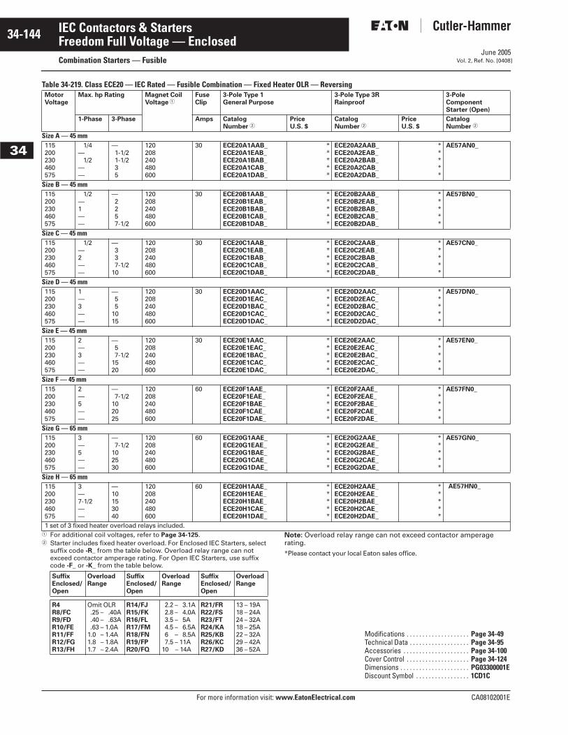
June 2005
34-144
For more information visit: www.EatonElectrical.com CA08102001E
IEC Contactors & Starters
34
Freedom Full Voltage — EnclosedCombination Starters — Fusible Vol. 2, Ref. No. [0408]
Table 34-219. Class ECE20 — IEC Rated — Fusible Combination — Fixed Heater OLR — Reversing
� For additional coil voltages, refer to Page 34-125.� Starter includes fixed heater overload. For Enclosed IEC Starters, select
suffix code -R_ from the table below. Overload relay range can not exceed contactor amperage rating. For Open IEC Starters, use suffix code -F_ or -K_ from the table below.
Note: Overload relay range can not exceed contactor amperage rating.*Please contact your local Eaton sales office.
MotorVoltage
Max. hp Rating Magnet Coil Voltage �
FuseClip
3-Pole Type 1 General Purpose
3-Pole Type 3RRainproof
3-Pole Component Starter (Open)
1-Phase 3-Phase Amps CatalogNumber �
PriceU.S. $
CatalogNumber �
PriceU.S. $
CatalogNumber �
Size A — 45 mm115200230460575
1/4— 1/2
——
—1-1/21-1/235
120208240480600
30 ECE20A1AAB_ECE20A1EAB_ECE20A1BAB_ECE20A1CAB_ECE20A1DAB_
*****
ECE20A2AAB_ECE20A2EAB_ECE20A2BAB_ECE20A2CAB_ECE20A2DAB_
*****
AE57AN0_
Size B — 45 mm115200230460575
1/2—1——
—2257-1/2
120208240480600
30 ECE20B1AAB_ECE20B1EAB_ECE20B1BAB_ECE20B1CAB_ECE20B1DAB_
*****
ECE20B2AAB_ECE20B2EAB_ECE20B2BAB_ECE20B2CAB_ECE20B2DAB_
*****
AE57BN0_
Size C — 45 mm115200230460575
1/2—2——
—337-1/2
10
120208240480600
30 ECE20C1AAB_ECE20C1EAB_ECE20C1BAB_ECE20C1CAB_ECE20C1DAB_
*****
ECE20C2AAB_ECE20C2EAB_ECE20C2BAB_ECE20C2CAB_ECE20C2DAB_
*****
AE57CN0_
Size D — 45 mm115200230460575
1—3——
—55
1015
120208240480600
30 ECE20D1AAC_ECE20D1EAC_ECE20D1BAC_ECE20D1CAC_ECE20D1DAC_
*****
ECE20D2AAC_ECE20D2EAC_ECE20D2BAC_ECE20D2CAC_ECE20D2DAC_
*****
AE57DN0_
Size E — 45 mm115200230460575
2—3——
—57-1/2
1520
120208240480600
30 ECE20E1AAC_ECE20E1EAC_ECE20E1BAC_ECE20E1CAC_ECE20E1DAC_
*****
ECE20E2AAC_ECE20E2EAC_ECE20E2BAC_ECE20E2CAC_ECE20E2DAC_
*****
AE57EN0_
Size F — 45 mm115200230460575
2—5——
—7-1/2
102025
120208240480600
60 ECE20F1AAE_ECE20F1EAE_ECE20F1BAE_ECE20F1CAE_ECE20F1DAE_
*****
ECE20F2AAE_ECE20F2EAE_ECE20F2BAE_ECE20F2CAE_ECE20F2DAE_
*****
AE57FN0_
Size G — 65 mm115200230460575
3—5——
—7-1/2
102530
120208240480600
60 ECE20G1AAE_ECE20G1EAE_ECE20G1BAE_ECE20G1CAE_ECE20G1DAE_
*****
ECE20G2AAE_ECE20G2EAE_ECE20G2BAE_ECE20G2CAE_ECE20G2DAE_
*****
AE57GN0_
Size H — 65 mm115200230460575
3—7-1/2——
—10153040
120208240480600
60 ECE20H1AAE_ECE20H1EAE_ECE20H1BAE_ECE20H1CAE_ECE20H1DAE_
*****
ECE20H2AAE_ECE20H2EAE_ECE20H2BAE_ECE20H2CAE_ECE20H2DAE_
*****
AE57HN0_
1 set of 3 fixed heater overload relays included.
SuffixEnclosed/Open
OverloadRange
SuffixEnclosed/Open
OverloadRange
SuffixEnclosed/Open
OverloadRange
R4R8/FCR9/FDR10/FER11/FFR12/FGR13/FH
Omit OLR.25 – .40A.40 – .63A.63 – 1.0A
1.0 – 1.4A1.8 – 1.8A1.7 – 2.4A
R14/FJR15/FKR16/FLR17/FMR18/FNR19/FPR20/FQ
2.2 – 3.1A2.8 – 4.0A3.5 – 5A4.5 – 6.5A6.5 – 8.5A7.5 – 11A
10.5 – 14A
R21/FRR22/FSR23/FTR24/KAR25/KBR26/KCR27/KD
13 – 19A18 – 24A24 – 32A18 – 25A22 – 32A29 – 42A36 – 52A
Modifications . . . . . . . . . . . . . . . . . . . . Page 34-49Technical Data . . . . . . . . . . . . . . . . . . . Page 34-95Accessories . . . . . . . . . . . . . . . . . . . . . Page 34-100Cover Control . . . . . . . . . . . . . . . . . . . . Page 34-124Dimensions . . . . . . . . . . . . . . . . . . . . . . PG03300001EDiscount Symbol . . . . . . . . . . . . . . . . . 1CD1C
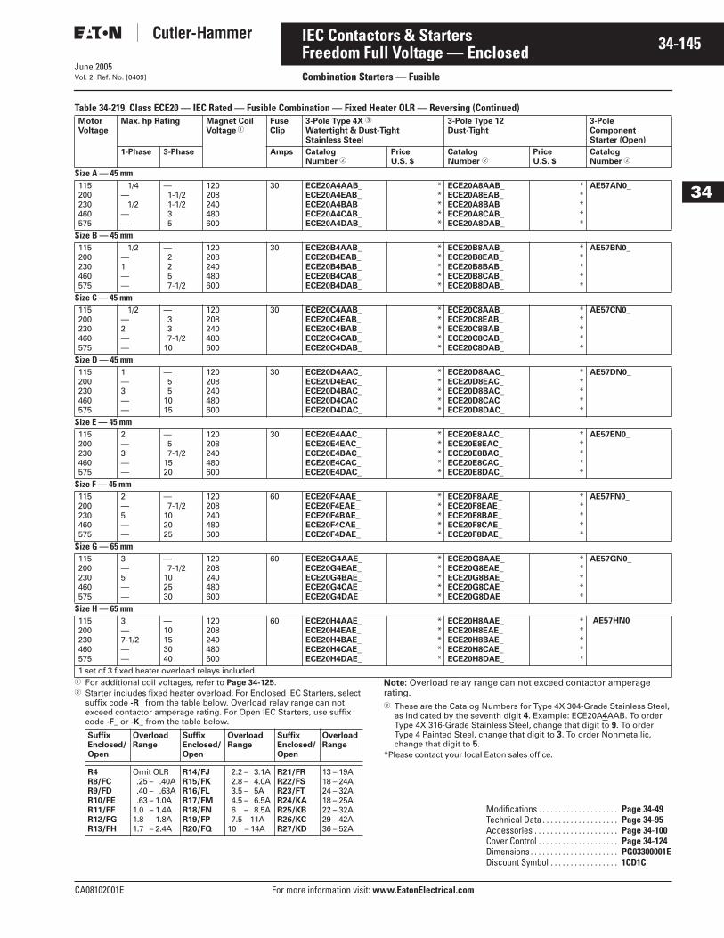
June 2005
CA08102001E For more information visit: www.EatonElectrical.com
34-145IEC Contactors & Starters
34
Freedom Full Voltage — EnclosedCombination Starters — FusibleVol. 2, Ref. No. [0409]
Table 34-219. Class ECE20 — IEC Rated — Fusible Combination — Fixed Heater OLR — Reversing (Continued)
� For additional coil voltages, refer to Page 34-125.� Starter includes fixed heater overload. For Enclosed IEC Starters, select
suffix code -R_ from the table below. Overload relay range can not exceed contactor amperage rating. For Open IEC Starters, use suffix code -F_ or -K_ from the table below.
Note: Overload relay range can not exceed contactor amperage rating.� These are the Catalog Numbers for Type 4X 304-Grade Stainless Steel,
as indicated by the seventh digit 4. Example: ECE20A4AAB. To order Type 4X 316-Grade Stainless Steel, change that digit to 9. To order Type 4 Painted Steel, change that digit to 3. To order Nonmetallic, change that digit to 5.
*Please contact your local Eaton sales office.
MotorVoltage
Max. hp Rating Magnet Coil Voltage �
FuseClip
3-Pole Type 4X �
Watertight & Dust-TightStainless Steel
3-Pole Type 12 Dust-Tight
3-Pole Component Starter (Open)
1-Phase 3-Phase Amps CatalogNumber �
PriceU.S. $
CatalogNumber �
PriceU.S. $
CatalogNumber �
Size A — 45 mm115200230460575
1/4— 1/2
——
—1-1/21-1/235
120208240480600
30 ECE20A4AAB_ECE20A4EAB_ECE20A4BAB_ECE20A4CAB_ECE20A4DAB_
*****
ECE20A8AAB_ECE20A8EAB_ECE20A8BAB_ECE20A8CAB_ECE20A8DAB_
*****
AE57AN0_
Size B — 45 mm115200230460575
1/2—1——
—2257-1/2
120208240480600
30 ECE20B4AAB_ECE20B4EAB_ECE20B4BAB_ECE20B4CAB_ECE20B4DAB_
*****
ECE20B8AAB_ECE20B8EAB_ECE20B8BAB_ECE20B8CAB_ECE20B8DAB_
*****
AE57BN0_
Size C — 45 mm115200230460575
1/2—2——
—337-1/2
10
120208240480600
30 ECE20C4AAB_ECE20C4EAB_ECE20C4BAB_ECE20C4CAB_ECE20C4DAB_
*****
ECE20C8AAB_ECE20C8EAB_ECE20C8BAB_ECE20C8CAB_ECE20C8DAB_
*****
AE57CN0_
Size D — 45 mm115200230460575
1—3——
—55
1015
120208240480600
30 ECE20D4AAC_ECE20D4EAC_ECE20D4BAC_ECE20D4CAC_ECE20D4DAC_
*****
ECE20D8AAC_ECE20D8EAC_ECE20D8BAC_ECE20D8CAC_ECE20D8DAC_
*****
AE57DN0_
Size E — 45 mm115200230460575
2—3——
—57-1/2
1520
120208240480600
30 ECE20E4AAC_ECE20E4EAC_ECE20E4BAC_ECE20E4CAC_ECE20E4DAC_
*****
ECE20E8AAC_ECE20E8EAC_ECE20E8BAC_ECE20E8CAC_ECE20E8DAC_
*****
AE57EN0_
Size F — 45 mm115200230460575
2—5——
—7-1/2
102025
120208240480600
60 ECE20F4AAE_ECE20F4EAE_ECE20F4BAE_ECE20F4CAE_ECE20F4DAE_
*****
ECE20F8AAE_ECE20F8EAE_ECE20F8BAE_ECE20F8CAE_ECE20F8DAE_
*****
AE57FN0_
Size G — 65 mm115200230460575
3—5——
—7-1/2
102530
120208240480600
60 ECE20G4AAE_ECE20G4EAE_ECE20G4BAE_ECE20G4CAE_ECE20G4DAE_
*****
ECE20G8AAE_ECE20G8EAE_ECE20G8BAE_ECE20G8CAE_ECE20G8DAE_
*****
AE57GN0_
Size H — 65 mm115200230460575
3—7-1/2——
—10153040
120208240480600
60 ECE20H4AAE_ECE20H4EAE_ECE20H4BAE_ECE20H4CAE_ECE20H4DAE_
*****
ECE20H8AAE_ECE20H8EAE_ECE20H8BAE_ECE20H8CAE_ECE20H8DAE_
*****
AE57HN0_
1 set of 3 fixed heater overload relays included.
SuffixEnclosed/Open
OverloadRange
SuffixEnclosed/Open
OverloadRange
SuffixEnclosed/Open
OverloadRange
R4R8/FCR9/FDR10/FER11/FFR12/FGR13/FH
Omit OLR.25 – .40A.40 – .63A.63 – 1.0A
1.0 – 1.4A1.8 – 1.8A1.7 – 2.4A
R14/FJR15/FKR16/FLR17/FMR18/FNR19/FPR20/FQ
2.2 – 3.1A2.8 – 4.0A3.5 – 5A4.5 – 6.5A6.5 – 8.5A7.5 – 11A
10.5 – 14A
R21/FRR22/FSR23/FTR24/KAR25/KBR26/KCR27/KD
13 – 19A18 – 24A24 – 32A18 – 25A22 – 32A29 – 42A36 – 52A
Modifications . . . . . . . . . . . . . . . . . . . . Page 34-49Technical Data . . . . . . . . . . . . . . . . . . . Page 34-95Accessories . . . . . . . . . . . . . . . . . . . . . Page 34-100Cover Control . . . . . . . . . . . . . . . . . . . . Page 34-124Dimensions . . . . . . . . . . . . . . . . . . . . . . PG03300001EDiscount Symbol . . . . . . . . . . . . . . . . . 1CD1C

June 2005
34-146
For more information visit: www.EatonElectrical.com CA08102001E
IEC Contactors & Starters
34
Freedom Full Voltage — EnclosedCombination Starters — GMCP Vol. 2, Ref. No. [0410]
Product SelectionTable 34-220. Class ECE22 — IEC Rated — Combination GMCP — Interchangeable Heater OLR — Non-reversing
� For additional coil voltages, see Page 34-125.� GMCP is rated for 480V maximum.*Please contact your local Eaton sales office.
Motor Voltage�
Max. hp Rating MagnetCoil Voltage�
GMCPRating(trip range)Amperes
3-Pole Type 1General Purpose
3-Pole Type 3RRainproof
3-Pole Component Starter (Open)
1-Phase 3-Phase CatalogNumber
PriceU.S. $
CatalogNumber
PriceU.S. $
CatalogNumber
Size A — 45 mm115200230460
— 1/6 1/6 1/2
— 1/2 1/2
1-1/2
120208240480
3 (15-30)
ECE22A1AABECE22A1EABECE22A1BABECE22A1CAB
****
ECE22A2AABECE22A2EABECE22A2BABECE22A2CAB
****
AE16ANS0ACAE16ANS0ECAE16ANS0BCAE16ANS0CC
Size B — 45 mm115200230460
1/4 1/2 1/2
1-1/2
—1-1/21-1/23
120208240480
7 (35-70)
ECE22B1AACECE22B1EACECE22B1BACECE22B1CAC
****
ECE22B2AACECE22B2EACECE22B2BACECE22B2CAC
****
AE16BNS0ACAE16BNS0ECAE16BNS0BCAE16BNS0CC
Size C — 45 mm115200230460
1/21-1/223
—337-1/2
120208240480
15 (75-150)
ECE22C1AADECE22C1EADECE22C1BADECE22C1CAD
***
825.
ECE22C2AADECE22C2EADECE22C2BADECE22C2CAD
****
AE16CNS0ACAE16CNS0ECAE16CNS0BCAE16CNS0CC
Size D — 45 mm115200230460
1—3—
—55
10
120208240480
30 (150-300)
ECE22D1AAEECE22D1EAEECE22D1BAEECE22D1CAE
****
ECE22D2AAEECE22D2EAEECE22D2BAEECE22D2CAE
****
AE16DNS0ACAE16DNS0ECAE16DNS0BCAE16DNS0CC
Size E — 45 mm115200230460
2—3—
—57-1/2
15
120208240480
30(150-300)
ECE22E1AAEECE22E1EAEECE22E1BAEECE22E1CAE
****
ECE22E2AAEECE22E2EAEECE22E2BAEECE22E2CAE
****
AE16ENS0ACAE16ENS0ECAE16ENS0BCAE16ENS0CC
Size F — 45 mm115200230460
2—5—
—7-1/2
1020
120208240480
50(250-500)
ECE22F1AAFECE22F1EAFECE22F1BAFECE22F1CAF
****
ECE22F2AAFECE22F2EAFECE22F2BAFECE22F2CAF
****
AE16FNS0ACAE16FNS0ECAE16FNS0BCAE16FNS0CC
Size G — 65 mm 115200230460
3—5—
—7-1/2
1025
120208240480
50(250-500)
ECE22G1AAFECE22G1EAFECE22G1BAFECE22G1CAF
****
ECE22G2AAFECE22G2EAFECE22G2BAFECE22G2CAF
****
AE16GNS0ABAE16GNS0EBAE16GNS0BBAE16GNS0CB
Size H — 65 mm115200230460
3—7-1/2—
—101530
120208240480
50(250-500)
ECE22H1AAFECE22H1EAFECE22H1BAFECE22H1CAF
****
ECE22H2AAFECE22H2EAFECE22H2BAFECE22H2CAF
****
AE16HNS0ABAE16HNS0EBAE16HNS0BBAE16HNS0CB
Starters do not include heater packs. Select 1 carton of 3 heater packs. For Heater Pack Selection, see Page 34-93.Starters with Electronic Overload, see Page 34-55 of Modification Codes.
Modifications . . . . . . . . . . . . . . . . . . . . Page 34-49Heater Pack Selection . . . . . . . . . . . . Page 34-93Technical Data . . . . . . . . . . . . . . . . . . . Page 34-95Accessories . . . . . . . . . . . . . . . . . . . . . Page 34-100Cover Control . . . . . . . . . . . . . . . . . . . . Page 34-124Dimensions . . . . . . . . . . . . . . . . . . . . . . PG03300001EDiscount Symbol . . . . . . . . . . . . . . . . . 1CD1C
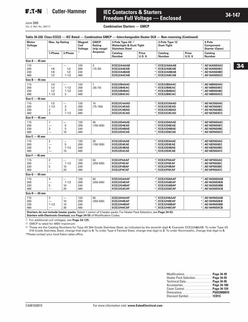
June 2005
CA08102001E For more information visit: www.EatonElectrical.com
34-147IEC Contactors & Starters
34
Freedom Full Voltage — EnclosedCombination Starters — GMCPVol. 2, Ref. No. [0411]
Table 34-220. Class ECE22 — IEC Rated — Combination GMCP — Interchangeable Heater OLR — Non-reversing (Continued)
� For additional coil voltages, see Page 34-125.� GMCP is rated for 480V maximum.� These are the Catalog Numbers for Type 4X 304-Grade Stainless Steel, as indicated by the seventh digit 4. Example: ECE22A4AAB. To order Type 4X
316-Grade Stainless Steel, change that digit to 9. To order Type 4 Painted Steel, change that digit to 3. To order Nonmetallic, change that digit to 5.*Please contact your local Eaton sales office.
Motor Voltage�
Max. hp Rating MagnetCoil Voltage�
GMCPRating(trip range)Amperes
3-Pole Type 4X �
Watertight & Dust-TightStainless Steel
3-Pole Type 12Dust-Tight
3-Pole Component Starter (Open)
1-Phase 3-Phase CatalogNumber
PriceU.S. $
CatalogNumber
PriceU.S. $
CatalogNumber
Size A — 45 mm115200230460
— 1/6 1/6 1/2
— 1/2 1/2
1-1/2
120208240480
3 (15-30)
ECE22A4AABECE22A4EABECE22A4BABECE22A4CAB
****
ECE22A8AABECE22A8EABECE22A8BABECE22A8CAB
****
AE16ANS0ACAE16ANS0ECAE16ANS0BCAE16ANS0CC
Size B — 45 mm115200230460
1/4 1/2 1/2
1-1/2
—1-1/21-1/23
120208240480
7 (35-70)
ECE22B4AACECE22B4EACECE22B4BACECE22B4CAC
****
ECE22B8AACECE22B8EACECE22B8BACECE22B8CAC
****
AE16BNS0ACAE16BNS0ECAE16BNS0BCAE16BNS0CC
Size C — 45 mm115200230460
1/21-1/223
—337-1/2
120208240480
15 (75-150)
ECE22C4AADECE22C4EADECE22C4BADECE22C4CAD
****
ECE22C8AADECE22C8EADECE22C8BADECE22C8CAD
****
AE16CNS0ACAE16CNS0ECAE16CNS0BCAE16CNS0CC
Size D — 45 mm115200230460
1—3—
—55
10
120208240480
30 (150-300)
ECE22D4AAEECE22D4EAEECE22D4BAEECE22D4CAE
****
ECE22D8AAEECE22D8EAEECE22D8BAEECE22D8CAE
****
AE16DNS0ACAE16DNS0ECAE16DNS0BCAE16DNS0CC
Size E — 45 mm115200230460
2—3—
—57-1/2
15
120208240480
30(150-300)
ECE22E4AAEECE22E4EAEECE22E4BAEECE22E4CAE
****
ECE22E8AAEECE22E8EAEECE22E8BAEECE22E8CAE
****
AE16ENS0ACAE16ENS0ECAE16ENS0BCAE16ENS0CC
Size F — 45 mm115200230460
2—5—
—7-1/2
1020
120208240480
50(250-500)
ECE22F4AAFECE22F4EAFECE22F4BAFECE22F4CAF
****
ECE22F8AAFECE22F8EAFECE22F8BAFECE22F8CAF
****
AE16FNS0ACAE16FNS0ECAE16FNS0BCAE16FNS0CC
Size G — 65 mm 115200230460
3—5—
—7-1/2
1025
120208240480
50(250-500)
ECE22G4AAFECE22G4EAFECE22G4BAFECE22G4CAF
****
ECE22G8AAFECE22G8EAFECE22G8BAFECE22G8CAF
****
AE16GNS0ABAE16GNS0EBAE16GNS0BBAE16GNS0CB
Size H — 65 mm115200230460
3—7-1/2—
—101530
120208240480
50(250-500)
ECE22H4AAFECE22H4EAFECE22H4BAFECE22H4CAF
****
ECE22H8AAFECE22H8EAFECE22H8BAFECE22H8CAF
****
AE16HNS0ABAE16HNS0EBAE16HNS0BBAE16HNS0CB
Starters do not include heater packs. Select 1 carton of 3 heater packs. For Heater Pack Selection, see Page 34-93.Starters with Electronic Overload, see Page 34-55 of Modification Codes.
Modifications. . . . . . . . . . . . . . . . . . . . Page 34-49Heater Pack Selection . . . . . . . . . . . . Page 34-93Technical Data. . . . . . . . . . . . . . . . . . . Page 34-95Accessories . . . . . . . . . . . . . . . . . . . . . Page 34-100Cover Control . . . . . . . . . . . . . . . . . . . . Page 34-124Dimensions. . . . . . . . . . . . . . . . . . . . . . PG03300001EDiscount Symbol . . . . . . . . . . . . . . . . . 1CD1C
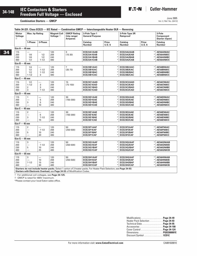
June 2005
34-148
For more information visit: www.EatonElectrical.com CA08102001E
IEC Contactors & Starters
34
Freedom Full Voltage — EnclosedCombination Starters — GMCP Vol. 2, Ref. No. [0412]
Table 34-221. Class ECE23 — IEC Rated — Combination GMCP — Interchangeable Heater OLR — Reversing
� For additional coil voltages, see Page 34-125.� GMCP is rated for 480V maximum.*Please contact your local Eaton sales office.
MotorVoltage�
Max. hp Rating Magnet Coil Voltage �
GMCP Rating(trip range)Amperes
3-Pole Type 1General Purpose
3-Pole Type 3RRainproof
3-Pole Component Starter (Open)
1-Phase 3-Phase CatalogNumber
PriceU.S. $
CatalogNumber
PriceU.S. $
CatalogNumber
Size A — 45 mm115200230460
— 1/6 1/6 1/2
— 1/2 1/2
1-1/2
120208240480
3(15-30)
ECE23A1AABECE23A1EABECE23A1BABECE23A1CAB
****
ECE23A2AABECE23A2EABECE23A2BABECE23A2CAB
****
AE56AN0ACAE56AN0ECAE56AN0BCAE56AN0CC
Size B — 45 mm115200230460
1/4 1/2 1/2
1-1/2
—1-1/21-1/23
120208240480
7(35-70)
ECE23B1AACECE23B1EACECE23B1BACECE23B1CAC
****
ECE23B2AACECE23B2EACECE23B2BACECE23B2CAC
****
AE56BN0ACAE56BN0ECAE56BN0BCAE56BN0CC
Size C — 45 mm115200230460
1/21-1/223
—337-1/2
120208240480
15(75-150)
ECE23C1AADECE23C1EADECE23C1BADECE23C1CAD
****
ECE23C2AADECE23C2EADECE23C2BADECE23C2CAD
****
AE56CN0ACAE56CN0ECAE56CN0BCAE56CN0CC
Size D — 45 mm115200230460
1—3—
—55
10
120208240480
30(150-300)
ECE23D1AAEECE23D1EAEECE23D1BAEECE23D1CAE
****
ECE23D2AAEECE23D2EAEECE23D2BAEECE23D2CAE
****
AE56DN0ACAE56DN0ECAE56DN0BCAE56DN0CC
Size E — 45 mm115200230460
2—3—
—57-1/2
15
120208240480
30(150-300)
ECE23E1AAEECE23E1EAEECE23E1BAEECE23E1CAE
****
ECE23E2AAEECE23E2EAEECE23E2BAEECE23E2CAE
****
AE56EN0ACAE56EN0ECAE56EN0BCAE56EN0CC
Size F — 45 mm115200230460
2—5—
—7-1/2
1020
120208240480
50(250-500)
ECE23F1AAFECE23F1EAFECE23F1BAFECE23F1CAF
****
ECE23F2AAFECE23F2EAFECE23F2BAFECE23F2CAF
****
AE56FN0ACAE56FN0ECAE56FN0BCAE56FN0CC
Size G — 65 mm115200230460
3—5—
—7-1/2
1025
120208240480
50(250-500)
ECE23G1AAFECE23G1EAFECE23G1BAFECE23G1CAF
****
ECE23G2AAFECE23G2EAFECE23G2BAFECE23G2CAF
****
AE56GN0ABAE56GN0EBAE56GN0BBAE56GN0CB
Size H — 65 mm115200230460
3—7-1/2—
—101530
120208240480
50(250-500)
ECE23H1AAFECE23H1EAFECE23H1BAFECE23H1CAF
****
ECE23H2AAFECE23H2EAFECE23H2BAFECE23H2CAF
****
AE56HN0ABAE56HN0EBAE56HN0BBAE56HN0CB
Starters do not include heater packs. Select 1 carton of 3 heater packs. For Heater Pack Selection, see Page 34-93.Starters with Electronic Overload, see Page 34-55 of Modification Codes.
Modifications . . . . . . . . . . . . . . . . . . . . Page 34-49Heater Pack Selection . . . . . . . . . . . . Page 34-93Technical Data . . . . . . . . . . . . . . . . . . . Page 34-95Accessories . . . . . . . . . . . . . . . . . . . . . Page 34-100Cover Control . . . . . . . . . . . . . . . . . . . . Page 34-124Dimensions . . . . . . . . . . . . . . . . . . . . . . PG03300001EDiscount Symbol . . . . . . . . . . . . . . . . . 1CD1C
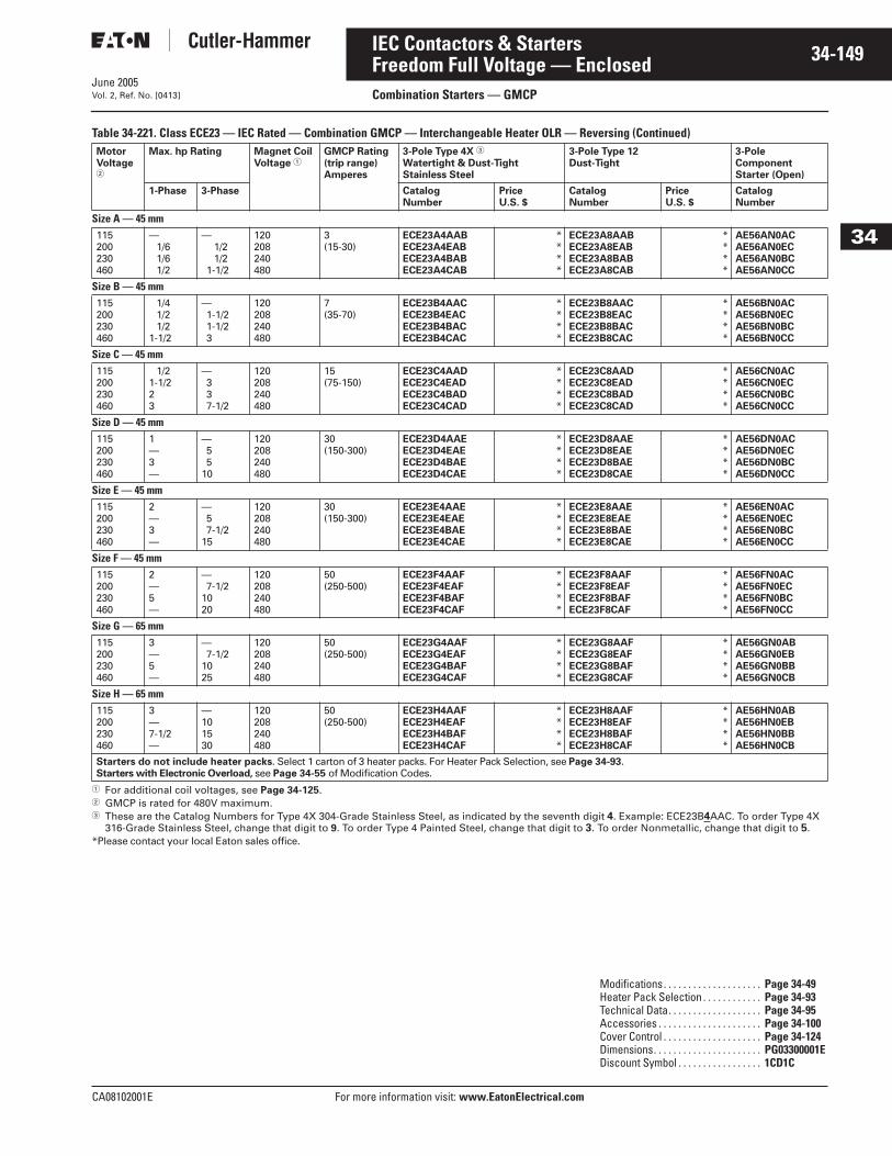
June 2005
CA08102001E For more information visit: www.EatonElectrical.com
34-149IEC Contactors & Starters
34
Freedom Full Voltage — EnclosedCombination Starters — GMCPVol. 2, Ref. No. [0413]
Table 34-221. Class ECE23 — IEC Rated — Combination GMCP — Interchangeable Heater OLR — Reversing (Continued)
� For additional coil voltages, see Page 34-125.� GMCP is rated for 480V maximum.� These are the Catalog Numbers for Type 4X 304-Grade Stainless Steel, as indicated by the seventh digit 4. Example: ECE23B4AAC. To order Type 4X
316-Grade Stainless Steel, change that digit to 9. To order Type 4 Painted Steel, change that digit to 3. To order Nonmetallic, change that digit to 5.*Please contact your local Eaton sales office.
MotorVoltage�
Max. hp Rating Magnet Coil Voltage �
GMCP Rating(trip range)Amperes
3-Pole Type 4X �
Watertight & Dust-TightStainless Steel
3-Pole Type 12Dust-Tight
3-Pole Component Starter (Open)
1-Phase 3-Phase CatalogNumber
PriceU.S. $
CatalogNumber
PriceU.S. $
CatalogNumber
Size A — 45 mm115200230460
— 1/6 1/6 1/2
— 1/2 1/2
1-1/2
120208240480
3(15-30)
ECE23A4AABECE23A4EABECE23A4BABECE23A4CAB
****
ECE23A8AABECE23A8EABECE23A8BABECE23A8CAB
****
AE56AN0ACAE56AN0ECAE56AN0BCAE56AN0CC
Size B — 45 mm115200230460
1/4 1/2 1/2
1-1/2
—1-1/21-1/23
120208240480
7(35-70)
ECE23B4AACECE23B4EACECE23B4BACECE23B4CAC
****
ECE23B8AACECE23B8EACECE23B8BACECE23B8CAC
****
AE56BN0ACAE56BN0ECAE56BN0BCAE56BN0CC
Size C — 45 mm115200230460
1/21-1/223
—337-1/2
120208240480
15(75-150)
ECE23C4AADECE23C4EADECE23C4BADECE23C4CAD
****
ECE23C8AADECE23C8EADECE23C8BADECE23C8CAD
****
AE56CN0ACAE56CN0ECAE56CN0BCAE56CN0CC
Size D — 45 mm115200230460
1—3—
—55
10
120208240480
30(150-300)
ECE23D4AAEECE23D4EAEECE23D4BAEECE23D4CAE
****
ECE23D8AAEECE23D8EAEECE23D8BAEECE23D8CAE
****
AE56DN0ACAE56DN0ECAE56DN0BCAE56DN0CC
Size E — 45 mm115200230460
2—3—
—57-1/2
15
120208240480
30(150-300)
ECE23E4AAEECE23E4EAEECE23E4BAEECE23E4CAE
****
ECE23E8AAEECE23E8EAEECE23E8BAEECE23E8CAE
****
AE56EN0ACAE56EN0ECAE56EN0BCAE56EN0CC
Size F — 45 mm115200230460
2—5—
—7-1/2
1020
120208240480
50(250-500)
ECE23F4AAFECE23F4EAFECE23F4BAFECE23F4CAF
****
ECE23F8AAFECE23F8EAFECE23F8BAFECE23F8CAF
****
AE56FN0ACAE56FN0ECAE56FN0BCAE56FN0CC
Size G — 65 mm115200230460
3—5—
—7-1/2
1025
120208240480
50(250-500)
ECE23G4AAFECE23G4EAFECE23G4BAFECE23G4CAF
****
ECE23G8AAFECE23G8EAFECE23G8BAFECE23G8CAF
****
AE56GN0ABAE56GN0EBAE56GN0BBAE56GN0CB
Size H — 65 mm115200230460
3—7-1/2—
—101530
120208240480
50(250-500)
ECE23H4AAFECE23H4EAFECE23H4BAFECE23H4CAF
****
ECE23H8AAFECE23H8EAFECE23H8BAFECE23H8CAF
****
AE56HN0ABAE56HN0EBAE56HN0BBAE56HN0CB
Starters do not include heater packs. Select 1 carton of 3 heater packs. For Heater Pack Selection, see Page 34-93.Starters with Electronic Overload, see Page 34-55 of Modification Codes.
Modifications. . . . . . . . . . . . . . . . . . . . Page 34-49Heater Pack Selection . . . . . . . . . . . . Page 34-93Technical Data. . . . . . . . . . . . . . . . . . . Page 34-95Accessories . . . . . . . . . . . . . . . . . . . . . Page 34-100Cover Control . . . . . . . . . . . . . . . . . . . . Page 34-124Dimensions. . . . . . . . . . . . . . . . . . . . . . PG03300001EDiscount Symbol . . . . . . . . . . . . . . . . . 1CD1C
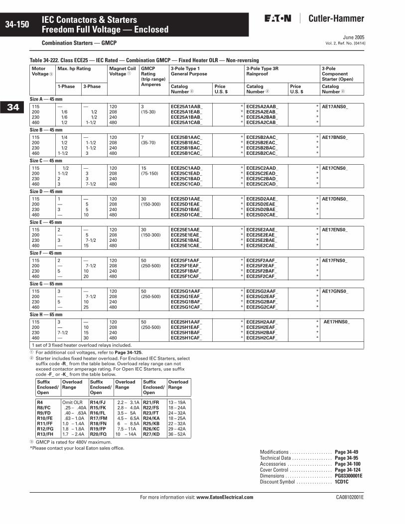
June 2005
34-150
For more information visit: www.EatonElectrical.com CA08102001E
IEC Contactors & Starters
34
Freedom Full Voltage — EnclosedCombination Starters — GMCP Vol. 2, Ref. No. [0414]
Table 34-222. Class ECE25 — IEC Rated — Combination GMCP — Fixed Heater OLR — Non-reversing
� For additional coil voltages, refer to Page 34-125.� Starter includes fixed heater overload. For Enclosed IEC Starters, select
suffix code -R_ from the table below. Overload relay range can not exceed contactor amperage rating. For Open IEC Starters, use suffix code -F_ or -K_ from the table below.
� GMCP is rated for 480V maximum.*Please contact your local Eaton sales office.
MotorVoltage �
Max. hp Rating Magnet Coil Voltage �
GMCPRating(trip range)Amperes
3-Pole Type 1General Purpose
3-Pole Type 3RRainproof
3-Pole Component Starter (Open)
1-Phase 3-Phase CatalogNumber �
PriceU.S. $
CatalogNumber �
PriceU.S. $
CatalogNumber �
Size A — 45 mm115200230460
— 1/6 1/6 1/2
— 1/2 1/2
1-1/2
120208240480
3 (15-30)
ECE25A1AAB_ECE25A1EAB_ECE25A1BAB_ECE25A1CAB_
****
ECE25A2AAB_ECE25A2EAB_ECE25A2BAB_ECE25A2CAB_
****
AE17ANS0_
Size B — 45 mm115200230460
1/4 1/2 1/2
1-1/2
—1-1/21-1/23
120208240480
7 (35-70)
ECE25B1AAC_ECE25B1EAC_ECE25B1BAC_ECE25B1CAC_
****
ECE25B2AAC_ECE25B2EAC_ECE25B2BAC_ECE25B2CAC_
****
AE17BNS0_
Size C — 45 mm115200230460
1/21-1/223
—337-1/2
120208240480
15 (75-150)
ECE25C1AAD_ECE25C1EAD_ECE25C1BAD_ECE25C1CAD_
****
ECE25C2AAD_ECE25C2EAD_ECE25C2BAD_ECE25C2CAD_
****
AE17CNS0_
Size D — 45 mm115200230460
1—3—
—55
10
120208240480
30 (150-300)
ECE25D1AAE_ECE25D1EAE_ECE25D1BAE_ECE25D1CAE_
****
ECE25D2AAE_ECE25D2EAE_ECE25D2BAE_ECE25D2CAE_
****
AE17DNS0_
Size E — 45 mm115200230460
2—3—
—57-1/2
15
120208240480
30(150-300)
ECE25E1AAE_ECE25E1EAE_ECE25E1BAE_ECE25E1CAE_
****
ECE25E2AAE_ECE25E2EAE_ECE25E2BAE_ECE25E2CAE_
****
AE17ENS0_
Size F — 45 mm115200230460
2—5—
—7-1/2
1020
120208240480
50(250-500)
ECE25F1AAF_ECE25F1EAF_ECE25F1BAF_ECE25F1CAF_
****
ECE25F2AAF_ECE25F2EAF_ECE25F2BAF_ECE25F2CAF_
****
AE17FNS0_
Size G — 65 mm115200230460
3—5—
—7-1/2
1025
120208240480
50(250-500)
ECE25G1AAF_ECE25G1EAF_ECE25G1BAF_ECE25G1CAF_
****
ECE25G2AAF_ECE25G2EAF_ECE25G2BAF_ECE25G2CAF_
****
AE17GNS0_
Size H — 65 mm115200230460
3—7-1/2—
—101530
120208240480
50(250-500)
ECE25H1AAF_ECE25H1EAF_ECE25H1BAF_ECE25H1CAF_
****
ECE25H2AAF_ECE25H2EAF_ECE25H2BAF_ECE25H2CAF_
****
AE17HNS0_
1 set of 3 fixed heater overload relays included.
SuffixEnclosed/Open
OverloadRange
SuffixEnclosed/Open
OverloadRange
SuffixEnclosed/Open
OverloadRange
R4R8/FCR9/FDR10/FER11/FFR12/FGR13/FH
Omit OLR.25 – .40A.40 – .63A.63 – 1.0A
1.0 – 1.4A1.8 – 1.8A1.7 – 2.4A
R14/FJR15/FKR16/FLR17/FMR18/FNR19/FPR20/FQ
2.2 – 3.1A2.8 – 4.0A3.5 – 5A4.5 – 6.5A6.5 – 8.5A7.5 – 11A
10.5 – 14A
R21/FRR22/FSR23/FTR24/KAR25/KBR26/KCR27/KD
13 – 19A18 – 24A24 – 32A18 – 25A22 – 32A29 – 42A36 – 52A
Modifications . . . . . . . . . . . . . . . . . . . Page 34-49Technical Data . . . . . . . . . . . . . . . . . . Page 34-95Accessories . . . . . . . . . . . . . . . . . . . . Page 34-100Cover Control . . . . . . . . . . . . . . . . . . . Page 34-124Dimensions . . . . . . . . . . . . . . . . . . . . . PG03300001EDiscount Symbol . . . . . . . . . . . . . . . . 1CD1C

June 2005
CA08102001E For more information visit: www.EatonElectrical.com
34-151IEC Contactors & Starters
34
Freedom Full Voltage — EnclosedCombination Starters — GMCPVol. 2, Ref. No. [0415]
Table 34-222. Class ECE25 — IEC Rated — Combination GMCP — Fixed Heater OLR — Non-reversing (Continued)
� For additional coil voltages, refer to Page 34-125.� Starter includes fixed heater overload. For Enclosed IEC Starters, select
suffix code -R_ from the table below. Overload relay range can not exceed contactor amperage rating. For Open IEC Starters, use suffix code -F_ or -K_ from the table below.
� GMCP is rated for 480V maximum.
� These are the Catalog Numbers for Type 4X 304-Grade Stainless Steel, as indicated by the seventh digit 4. Example: ECE25A4AAB. To order Type 4X 316-Grade Stainless Steel, change that digit to 9. To order Type 4 Painted Steel, change that digit to 3. To order Nonmetallic, change that digit to 5.
*Please contact your local Eaton sales office.
MotorVoltage �
Max. hp Rating Magnet Coil Voltage �
GMCPRating(trip range)Amperes
3-Pole Type 4X �
Watertight & Dust-TightStainless Steel
3-Pole Type 12Dust-Tight
3-Pole Component Starter (Open)
1-Phase 3-Phase CatalogNumber �
PriceU.S. $
CatalogNumber �
PriceU.S. $
CatalogNumber �
Size A — 45 mm115200230460
— 1/6 1/6 1/2
— 1/2 1/2
1-1/2
120208240480
3 (15-30)
ECE25A4AAB_ECE25A4EAB_ECE25A4BAB_ECE25A4CAB_
****
ECE25A8AAB_ECE25A8EAB_ECE25A8BAB_ECE25A8CAB_
****
AE17ANS0_
Size B — 45 mm115200230460
1/4 1/2 1/2
1-1/2
—1-1/21-1/23
120208240480
7 (35-70)
ECE25B4AAC_ECE25B4EAC_ECE25B4BAC_ECE25B4CAC_
****
ECE25B8AAC_ECE25B8EAC_ECE25B8BAC_ECE25B8CAC_
****
AE17BNS0_
Size C — 45 mm115200230460
1/21-1/223
—337-1/2
120208240480
15 (75-150)
ECE25C4AAD_ECE25C4EAD_ECE25C4BAD_ECE25C4CAD_
****
ECE25C8AAD_ECE25C8EAD_ECE25C8BAD_ECE25C8CAD_
****
AE17CNS0_
Size D — 45 mm115200230460
1—3—
—55
10
120208240480
30 (150-300)
ECE25D4AAE_ECE25D4EAE_ECE25D4BAE_ECE25D4CAE_
****
ECE25D8AAE_ECE25D8EAE_ECE25D8BAE_ECE25D8CAE_
****
AE17DNS0_
Size E — 45 mm115200230460
2—3—
—57-1/2
15
120208240480
30(150-300)
ECE25E4AAE_ECE25E4EAE_ECE25E4BAE_ECE25E4CAE_
****
ECE25E8AAE_ECE25E8EAE_ECE25E8BAE_ECE25E8CAE_
****
AE17ENS0_
Size F — 45 mm115200230460
2—5—
—7-1/2
1020
120208240480
50(250-500)
ECE25F4AAF_ECE25F4EAF_ECE25F4BAF_ECE25F4CAF_
****
ECE25F8AAF_ECE25F8EAF_ECE25F8BAF_ECE25F8CAF_
****
AE17FNS0_
Size G — 65 mm115200230460
3—5—
—7-1/2
1025
120208240480
50(250-500)
ECE25G4AAF_ECE25G4EAF_ECE25G4BAF_ECE25G4CAF_
****
ECE25G8AAF_ECE25G8EAF_ECE25G8BAF_ECE25G8CAF_
****
AE17GNS0_
Size H — 65 mm115200230460
3—7-1/2—
—101530
120208240480
50(250-500)
ECE25H4AAF_ECE25H4EAF_ECE25H4BAF_ECE25H4CAF_
****
ECE25H8AAF_ECE25H8EAF_ECE25H8BAF_ECE25H8CAF_
****
AE17HNS0_
1 set of 3 fixed heater overload relays included.
SuffixEnclosed/Open
OverloadRange
SuffixEnclosed/Open
OverloadRange
SuffixEnclosed/Open
OverloadRange
R4R8/FCR9/FDR10/FER11/FFR12/FGR13/FH
Omit OLR.25 – .40A.40 – .63A.63 – 1.0A
1.0 – 1.4A1.8 – 1.8A1.7 – 2.4A
R14/FJR15/FKR16/FLR17/FMR18/FNR19/FPR20/FQ
2.2 – 3.1A2.8 – 4.0A3.5 – 5A4.5 – 6.5A6.5 – 8.5A7.5 – 11A
10.5 – 14A
R21/FRR22/FSR23/FTR24/KAR25/KBR26/KCR27/KD
13 – 19A18 – 24A24 – 32A18 – 25A22 – 32A29 – 42A36 – 52A
Modifications . . . . . . . . . . . . . . . . . . . . Page 34-49Technical Data . . . . . . . . . . . . . . . . . . . Page 34-95Accessories . . . . . . . . . . . . . . . . . . . . . Page 34-100Cover Control . . . . . . . . . . . . . . . . . . . . Page 34-124Dimensions . . . . . . . . . . . . . . . . . . . . . . PG03300001EDiscount Symbol . . . . . . . . . . . . . . . . . 1CD1C

June 2005
34-152
For more information visit: www.EatonElectrical.com CA08102001E
IEC Contactors & Starters
34
Freedom Full Voltage — EnclosedCombination Starters — GMCP Vol. 2, Ref. No. [0416]
Table 34-223. Class ECE26 — IEC Rated — Combination GMCP — Fixed Heater OLR — Reversing
� For additional coil voltages, refer to Page 34-125.� Starter includes fixed heater overload. For Enclosed IEC Starters, select
suffix code -R_ from the table below. Overload relay range can not exceed contactor amperage rating. For Open IEC Starters, use suffix code -F_ or -K_ from the table below.
� GMCP is rated for 480V maximum.*Please contact your local Eaton sales office.
MotorVoltage �
Max. hp Rating Magnet Coil Voltage �
GMCPRating(trip range)Amperes
3-Pole Type 1General Purpose
3-Pole Type 3RRainproof
3-Pole Component Starter (Open)
1-Phase 3-Phase CatalogNumber �
PriceU.S. $
CatalogNumber �
PriceU.S. $
CatalogNumber �
Size A — 45 mm115200230460
— 1/6 1/6 1/2
— 1/2 1/2
1-1/2
120208240480
3(15-30)
ECE26A1AAB_ECE26A1EAB_ECE26A1BAB_ECE26A1CAB_
****
ECE26A2AAB_ECE26A2EAB_ECE26A2BAB_ECE26A2CAB_
****
AE57AN0_
Size B — 45 mm115200230460
1/4 1/2 1/2
1-1/2
—1-1/21-1/23
120208240480
7(35-70)
ECE26B1AAC_ECE26B1EAC_ECE26B1BAC_ECE26B1CAC_
****
ECE26B2AAC_ECE26B2EAC_ECE26B2BAC_ECE26B2CAC_
****
AE57BN0_
Size C — 45 mm115200230460
1/21-1/223
—337-1/2
120208240480
15(75-150)
ECE26C1AAD_ECE26C1EAD_ECE26C1BAD_ECE26C1CAD_
****
ECE26C2AAD_ECE26C2EAD_ECE26C2BAD_ECE26C2CAD_
****
AE57CN0_
Size D — 45 mm115200230460
1—3—
—55
10
120208240480
30(150-300)
ECE26D1AAE_ECE26D1EAE_ECE26D1BAE_ECE26D1CAE_
****
ECE26D2AAE_ECE26D2EAE_ECE26D2BAE_ECE26D2CAE_
****
AE57DN0_
Size E — 45 mm115200230460
2—3—
—57-1/2
15
120208240480
30(150-300)
ECE26E1AAE_ECE26E1EAE_ECE26E1BAE_ECE26E1CAE_
****
ECE26E2AAE_ECE26E2EAE_ECE26E2BAE_ECE26E2CAE_
****
AE57EN0_
Size F — 45 mm115200230460
2—5—
—7-1/2
1020
120208240480
50(250-500)
ECE26F1AAF_ECE26F1EAF_ECE26F1BAF_ECE26F1CAF_
****
ECE26F2AAF_ECE26F2EAF_ECE26F2BAF_ECE26F2CAF_
****
AE57FN0_
Size G — 65 mm115200230460
3—5—
—7-1/2
1025
120208240480
50(250-500)
ECE26G1AAF_ECE26G1EAF_ECE26G1BAF_ECE26G1CAF_
****
ECE26G2AAF_ECE26G2EAF_ECE26G2BAF_ECE26G2CAF_
****
AE57GN0_
Size H — 65 mm115200230460
3—7-1/2—
—101530
120208240480
50(250-500)
ECE26H1AAF_ECE26H1EAF_ECE26H1BAF_ECE26H1CAF_
****
ECE26H2AAF_ECE26H2EAF_ECE26H2BAF_ECE26H2CAF_
****
AE57HN0_
1 set of 3 fixed heater overload relays included.
SuffixEnclosed/Open
OverloadRange
SuffixEnclosed/Open
OverloadRange
SuffixEnclosed/Open
OverloadRange
R4R8/FCR9/FDR10/FER11/FFR12/FGR13/FH
Omit OLR.25 – .40A.40 – .63A.63 – 1.0A
1.0 – 1.4A1.8 – 1.8A1.7 – 2.4A
R14/FJR15/FKR16/FLR17/FMR18/FNR19/FPR20/FQ
2.2 – 3.1A2.8 – 4.0A3.5 – 5A4.5 – 6.5A6.5 – 8.5A7.5 – 11A
10.5 – 14A
R21/FRR22/FSR23/FTR24/KAR25/KBR26/KCR27/KD
13 – 19A18 – 24A24 – 32A18 – 25A22 – 32A29 – 42A36 – 52A
Modifications . . . . . . . . . . . . . . . . . . . Page 34-49Technical Data . . . . . . . . . . . . . . . . . . Page 34-95Accessories . . . . . . . . . . . . . . . . . . . . Page 34-100Cover Control . . . . . . . . . . . . . . . . . . . Page 34-124Dimensions . . . . . . . . . . . . . . . . . . . . . PG03300001EDiscount Symbol . . . . . . . . . . . . . . . . 1CD1C
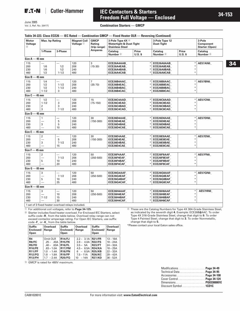
June 2005
CA08102001E For more information visit: www.EatonElectrical.com
34-153IEC Contactors & Starters
34
Freedom Full Voltage — EnclosedCombination Starters — GMCPVol. 2, Ref. No. [0417]
Table 34-223. Class ECE26 — IEC Rated — Combination GMCP — Fixed Heater OLR — Reversing (Continued)
� For additional coil voltages, refer to Page 34-125.� Starter includes fixed heater overload. For Enclosed IEC Starters, select
suffix code -R_ from the table below. Overload relay range can not exceed contactor amperage rating. For Open IEC Starters, use suffix code -F_ or -K_ from the table below.
� GMCP is rated for 480V maximum.
� These are the Catalog Numbers for Type 4X 304-Grade Stainless Steel, as indicated by the seventh digit 4. Example: ECE26B4AAC. To order Type 4X 316-Grade Stainless Steel, change that digit to 9. To order Type 4 Painted Steel, change that digit to 3. To order Nonmetallic, change that digit to 5.
*Please contact your local Eaton sales office.
MotorVoltage �
Max. hp Rating Magnet Coil Voltage �
GMCPRating(trip range)Amperes
3-Pole Type 4X �
Watertight & Dust-TightStainless Steel
3-Pole Type 12Dust-Tight
3-Pole Component Starter (Open)
1-Phase 3-Phase CatalogNumber �
PriceU.S. $
CatalogNumber �
PriceU.S. $
CatalogNumber �
Size A — 45 mm115200230460
— 1/6 1/6 1/2
— 1/2 1/2
1-1/2
120208240480
3(15-30)
ECE26A4AAB_ECE26A4EAB_ECE26A4BAB_ECE26A4CAB_
****
ECE26A8AAB_ECE26A8EAB_ECE26A8BAB_ECE26A8CAB_
****
AE57AN0_
Size B — 45 mm115200230460
1/4 1/2 1/2
1-1/2
—1-1/21-1/23
120208240480
7(35-70)
ECE26B4AAC_ECE26B4EAC_ECE26B4BAC_ECE26B4CAC_
****
ECE26B8AAC_ECE26B8EAC_ECE26B8BAC_ECE26B8CAC_
****
AE57BN0_
Size C — 45 mm115200230460
1/21-1/223
—337-1/2
120208240480
15(75-150)
ECE26C4AAD_ECE26C4EAD_ECE26C4BAD_ECE26C4CAD_
****
ECE26C8AAD_ECE26C8EAD_ECE26C8BAD_ECE26C8CAD_
****
AE57CN0_
Size D — 45 mm115200230460
1—3—
—55
10
120208240480
30(150-300)
ECE26D4AAE_ECE26D4EAE_ECE26D4BAE_ECE26D4CAE_
****
ECE26D8AAE_ECE26D8EAE_ECE26D8BAE_ECE26D8CAE_
****
AE57DN0_
Size E — 45 mm115200230460
2—3—
—57-1/2
15
120208240480
30(150-300)
ECE26E4AAE_ECE26E4EAE_ECE26E4BAE_ECE26E4CAE_
****
ECE26E8AAE_ECE26E8EAE_ECE26E8BAE_ECE26E8CAE_
****
AE57EN0_
Size F — 45 mm115200230460
2—5—
—7-1/2
1020
120208240480
50(250-500)
ECE26F4AAF_ECE26F4EAF_ECE26F4BAF_ECE26F4CAF_
****
ECE26F8AAF_ECE26F8EAF_ECE26F8BAF_ECE26F8CAF_
****
AE57FN0_
Size G — 65 mm115200230460
3—5—
—7-1/2
1025
120208240480
50(250-500)
ECE26G4AAF_ECE26G4EAF_ECE26G4BAF_ECE26G4CAF_
****
ECE26G8AAF_ECE26G8EAF_ECE26G8BAF_ECE26G8CAF_
****
AE57GN0_
Size H — 65 mm115200230460
3—7-1/2—
—101530
120208240480
50(250-500)
ECE26H4AAF_ECE26H4EAF_ECE26H4BAF_ECE26H4CAF_
****
ECE26H8AAF_ECE26H8EAF_ECE26H8BAF_ECE26H8CAF_
****
AE57HN0_
1 set of 3 fixed heater overload relays included.
SuffixEnclosed/Open
OverloadRange
SuffixEnclosed/Open
OverloadRange
SuffixEnclosed/Open
OverloadRange
R4R8/FCR9/FDR10/FER11/FFR12/FGR13/FH
Omit OLR.25 – .40A.40 – .63A.63 – 1.0A
1.0 – 1.4A1.8 – 1.8A1.7 – 2.4A
R14/FJR15/FKR16/FLR17/FMR18/FNR19/FPR20/FQ
2.2 – 3.1A2.8 – 4.0A3.5 – 5A4.5 – 6.5A6.5 – 8.5A7.5 – 11A
10.5 – 14A
R21/FRR22/FSR23/FTR24/KAR25/KBR26/KCR27/KD
13 – 19A18 – 24A24 – 32A18 – 25A22 – 32A29 – 42A36 – 52A
Modifications . . . . . . . . . . . . . . . . . . . . Page 34-49Technical Data . . . . . . . . . . . . . . . . . . . Page 34-95Accessories . . . . . . . . . . . . . . . . . . . . . Page 34-100Cover Control . . . . . . . . . . . . . . . . . . . . Page 34-124Dimensions . . . . . . . . . . . . . . . . . . . . . . PG03300001EDiscount Symbol . . . . . . . . . . . . . . . . . 1CD1C
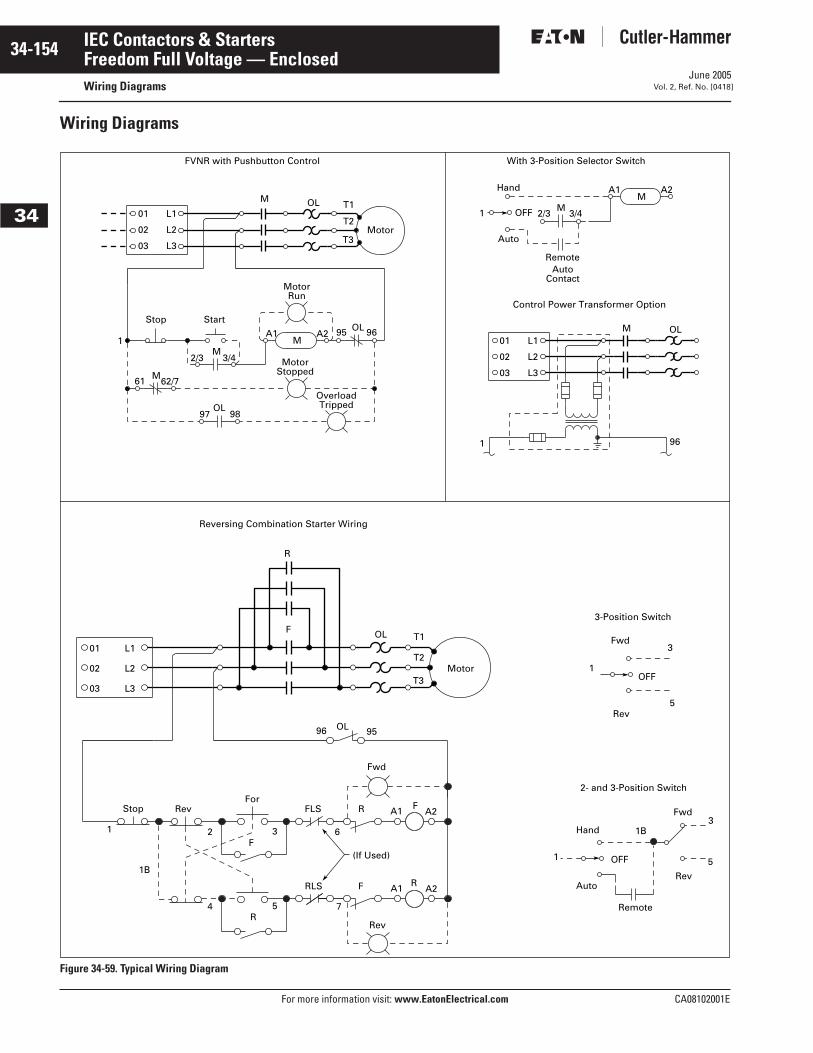
June 2005
34-154
For more information visit: www.EatonElectrical.com CA08102001E
IEC Contactors & Starters
34
Freedom Full Voltage — EnclosedWiring Diagrams Vol. 2, Ref. No. [0418]
Wiring Diagrams
Figure 34-59. Typical Wiring Diagram
01
03
02
1 96
L3
L1
L2
M OL
01
03
02
L3
L1
L2
M OL
MotorT3
T2
T1
Stop
61
1
9897
OverloadTripped
A2
3/42/3
62/7M
OL
M
Start
MotorStopped
A1M
MotorRun
96OL95
Auto
RemoteAuto
Contact
1 2/3OFF
Hand
M3/4
A1M
A2
With 3-Position Selector SwitchFVNR with Pushbutton Control
Control Power Transformer Option
02
03
01
L2
L3
L1OLF
R
Motor
T1
T3
T2
Stop
1
4
1B
2
R5
F3
Rev
A1
(If Used)
7
RLS F
6
RA2
RevFor
A1FLS R
Fwd
A2F
95OL96
1OFF
Rev5
3-Position Switch
Fwd3
1
Hand
Auto
Remote
Fwd
Rev
OFF
1B
5
3
2- and 3-Position Switch
Reversing Combination Starter Wiring
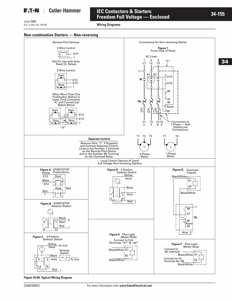
June 2005
CA08102001E For more information visit: www.EatonElectrical.com
34-155IEC Contactors & Starters
34
Freedom Full Voltage — EnclosedWiring DiagramsVol. 2, Ref. No. [0419]
Non-combination Starters — Non-reversing
Figure 34-60. Typical Wiring Diagram
Remote Pilot Devices Connections for Non-reversing Starter
2-Wire Control
3/141
2/133/14
1
2/13
3/14
1
Not for Use with Auto Reset OL Relays
3-Wire Control
Start
When More Than One Pushbutton Station is Used, Omit Connector“A” and Connect per
Sketch Below
Stop
Start
“A”
Stop Stop
Start
Separate Control
Remove Wire “C” if Suppliedand Connect Separate Control
Lines to the Number 1 Terminalon the Remote Pilot Device
and to the Number 96 Terminalon the Overload Relay.
AC Lines
1L1
A1 A2
3L2
5L3
“C”
1
M
OL
2/T1
4/T2
6/T3
2/13
3/14
98
Figure 1Front View of Panel
9796
Reset
95
T12
T1 T2 T3 T1 T2
T24
T36
T24
Conversion to1-Phase — Add
Dotted LineConnections.
3-PhaseMotor
1-PhaseMotor
Local Control Options (If Used)Full Voltage Non-reversing Starters
Figure A START/STOP PushbuttonsYellow
2/13 Start
Black3/14 3 4
RedStop Red
1 1 2
Figure B START/STOP Selector Switch
3 1
4 2
BlackStart
Red
3
1
Figure C 3-PositionSelector Switch
YellowHand To Coil
RemoteSwitch
BlackAuto3
4
3
4
1Red
To Coil
Figure D 2-PositonSelector Switch
YellowHand
Black
Auto
Red 1
1 3
2 4
Figure E Pilot Light(Motor RUN)
Connect to CoilTerminals “A1” & “A2”
Black/White X1
X2
Black/White
Figure F Pilot Light(Motor Stop)
Connect to NC Interlock
Black/White X1
X2Connect to OLTerminal No. 96
Black/White
Figure G OverloadTripped
Black/White
Black/White
X1
X2
198
97
96Reset95
OL
Wire “C”
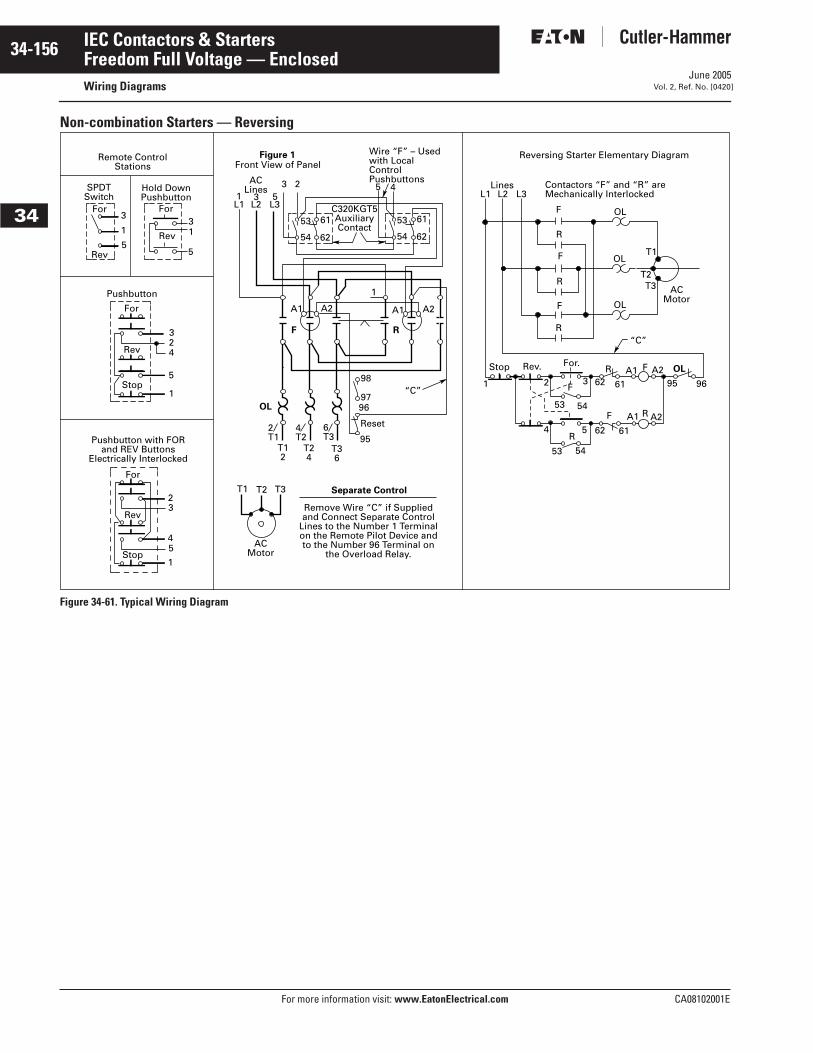
June 2005
34-156
For more information visit: www.EatonElectrical.com CA08102001E
IEC Contactors & Starters
34
Freedom Full Voltage — EnclosedWiring Diagrams Vol. 2, Ref. No. [0420]
Non-combination Starters — Reversing
Figure 34-61. Typical Wiring Diagram
Remote ControlStations
SPDTSwitch
For3
1
5Rev
Rev
For31
5
Hold DownPushbutton
324
5
1
Pushbutton
For
Rev
Stop
Pushbutton with FOR and REV Buttons
Electrically Interlocked
For
23
45
1
Rev
Stop
Figure 1Front View of Panel
ACLines 3 2
1 3 5L1 L2 L3
53
54
61
62
C320KGT5AuxiliaryContact
53
54
61
62
Wire “F” – Usedwith LocalControlPushbuttons
5 4
A1
F
A2
1
A1 A2
R
OL
98
9796
“C”
Reset
952T1
4T2
6T3
T12
T24
T36
T1 T2 T3
ACMotor
Separate Control
Remove Wire “C” if Suppliedand Connect Separate Control
Lines to the Number 1 Terminalon the Remote Pilot Device andto the Number 96 Terminal on
the Overload Relay.
“C”
Reversing Starter Elementary Diagram
L1 L2 L3Lines Contactors “F” and “R” are
Mechanically Interlocked
F
R
F
R
F
R
OL
OL
OL
ACMotor
Stop Rev. For.
1 2
4
53 54
F3 62 61 95 96
F
R
A1 R A25 62 61
R A1 F A2 OL
53 54
T1
T2T3