table c1 - kroftman.com€¦ · table c1: characteristic values for tension loads, steel zinc...
TRANSCRIPT
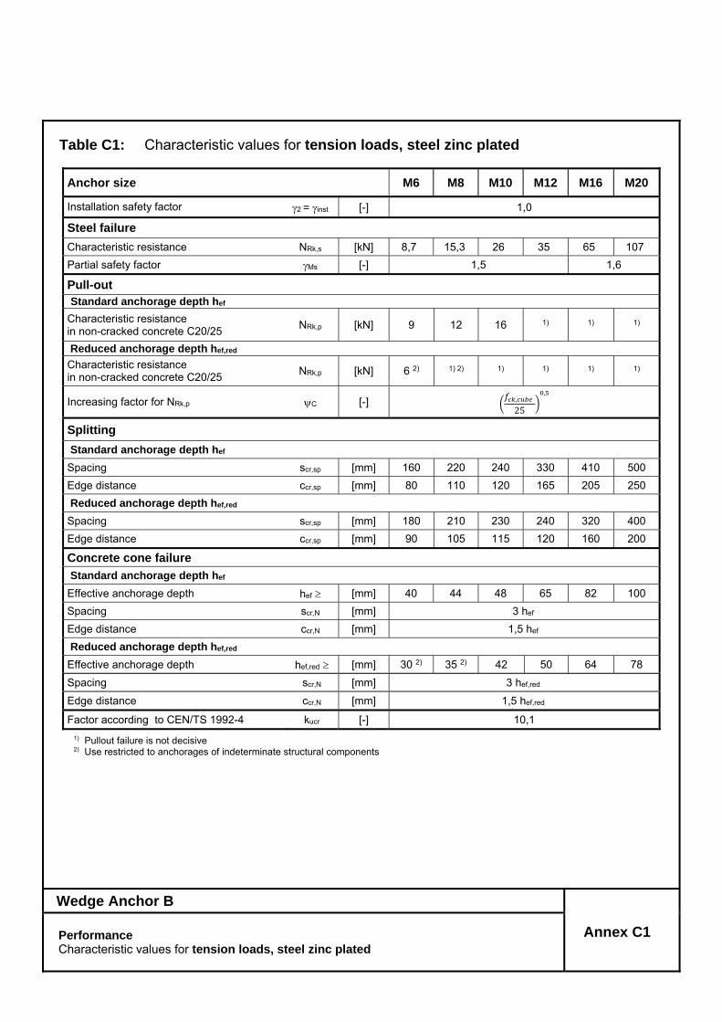
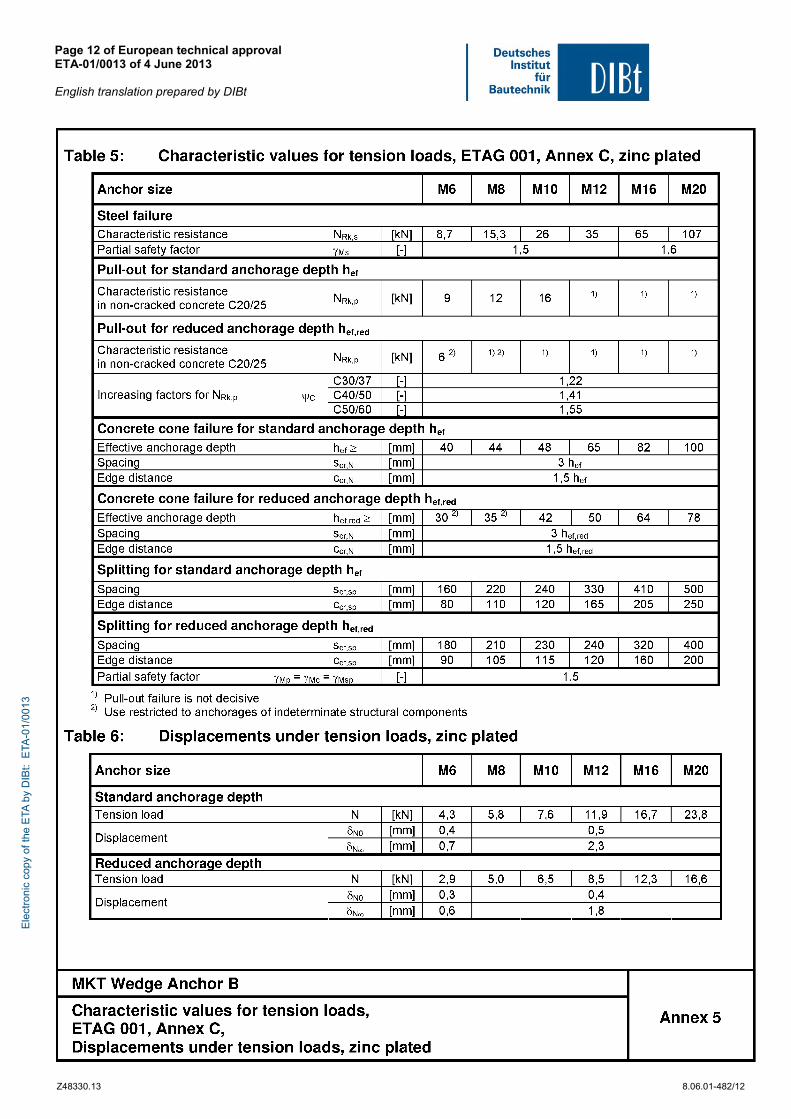
Table C1: Characteristic values for tension loads, steel zinc plated
Anchor size M6 M8 M10 M12 M16 M20
Installation safety factor 2 = inst [-] 1,0
Steel failure
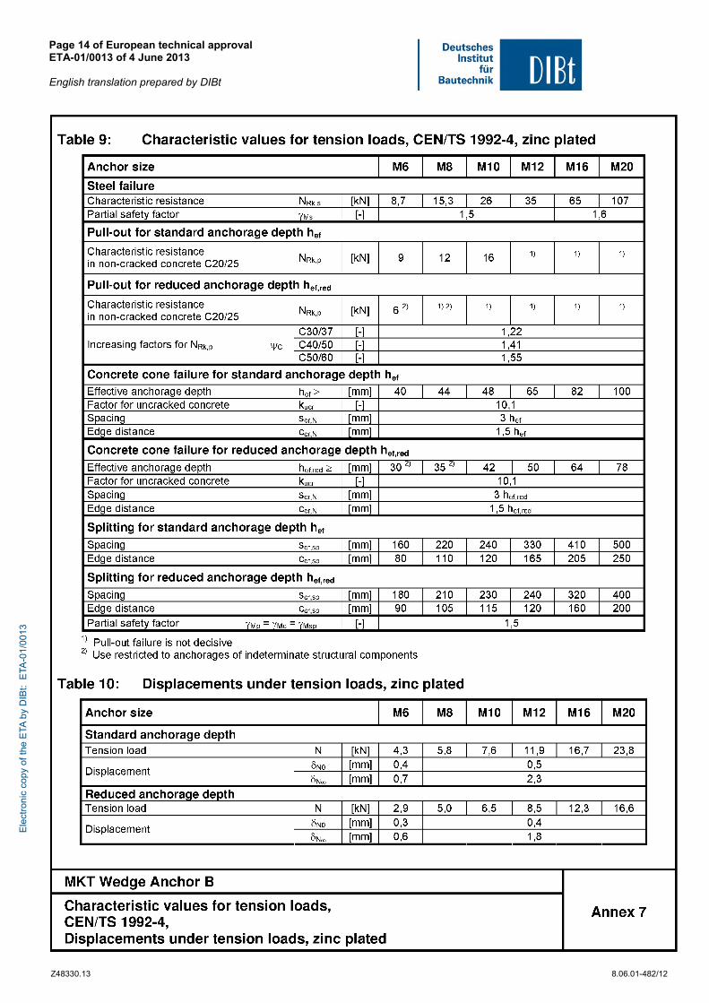
Characteristic resistance NRk,s [kN] 8,7 15,3 26 35 65 107
Partial safety factor Ms [-] 1,5 1,6
Pull-out Standard anchorage depth hef
Characteristic resistance in non-cracked concrete C20/25
NRk,p [kN] 9 12 16 1) 1) 1)
Reduced anchorage depth hef,red Characteristic resistance in non-cracked concrete C20/25
NRk,p [kN] 6 2) 1) 2) 1) 1) 1) 1)
Increasing factor for NRk,p C [-] , 25
,
Splitting
Standard anchorage depth hef
Spacing scr,sp [mm] 160 220 240 330 410 500
Edge distance ccr,sp [mm] 80 110 120 165 205 250
Reduced anchorage depth hef,red
Spacing scr,sp [mm] 180 210 230 240 320 400
Edge distance ccr,sp [mm] 90 105 115 120 160 200
Concrete cone failure
Standard anchorage depth hef
Effective anchorage depth hef [mm] 40 44 48 65 82 100
Spacing scr,N [mm] 3 hef
Edge distance ccr,N [mm] 1,5 hef
Reduced anchorage depth hef,red
Effective anchorage depth hef,red [mm] 30 2) 35 2) 42 50 64 78
Spacing scr,N [mm] 3 hef,red
Edge distance ccr,N [mm] 1,5 hef,red
Factor according to CEN/TS 1992-4 kucr [-] 10,1
1) Pullout failure is not decisive 2) Use restricted to anchorages of indeterminate structural components
Wedge Anchor B
Annex C1 Performance Characteristic values for tension loads, steel zinc plated
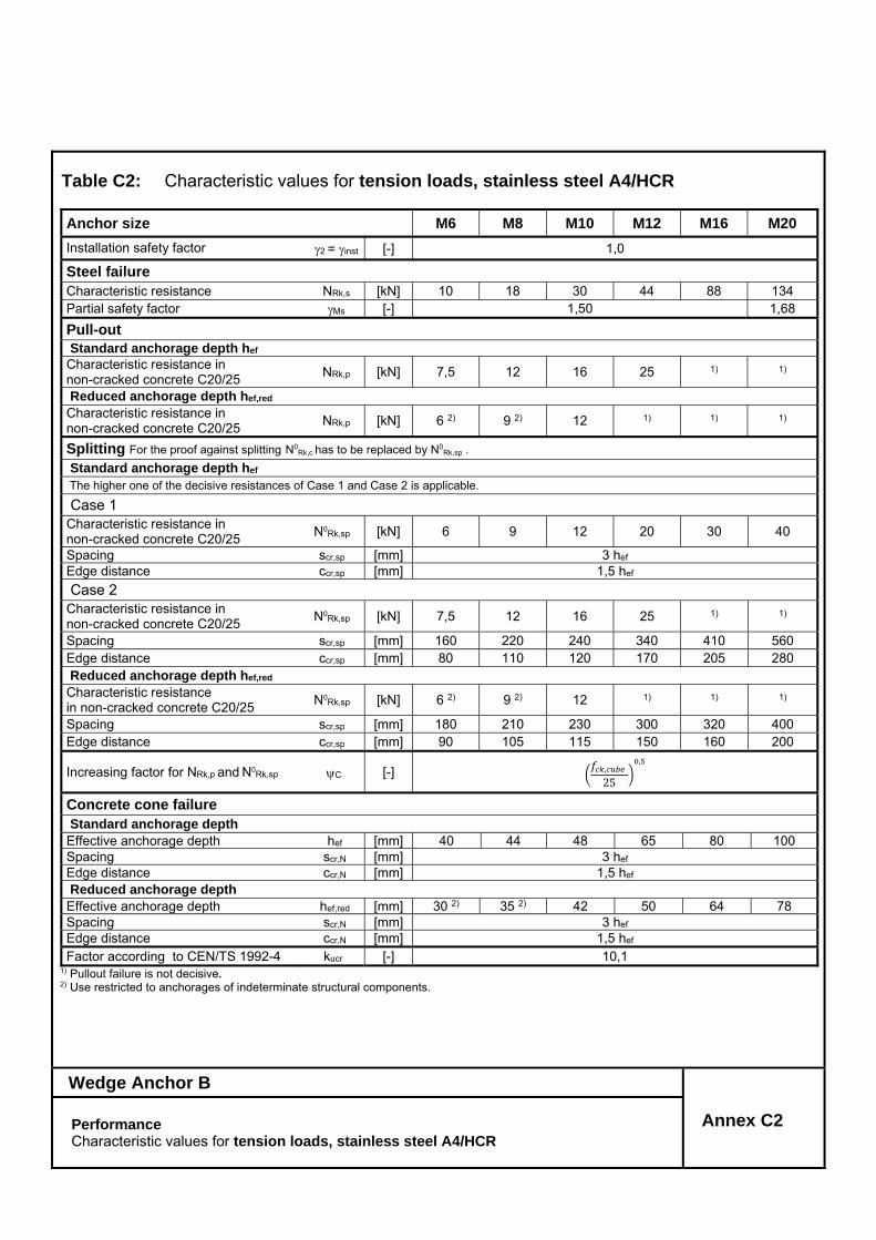
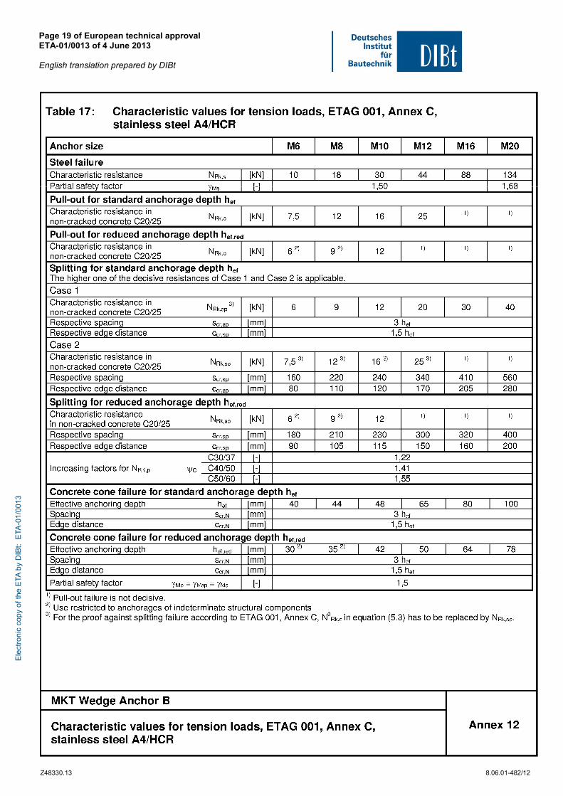
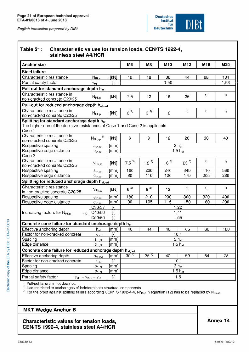
Table C2: Characteristic values for tension loads, stainless steel A4/HCR
Anchor size M6 M8 M10 M12 M16 M20
Installation safety factor 2 = inst [-] 1,0
Steel failure
Characteristic resistance NRk,s [kN] 10 18 30 44 88 134 Partial safety factor Ms
[-] 1,50 1,68
Pull-out
Standard anchorage depth hef
Characteristic resistance in non-cracked concrete C20/25
NRk,p [kN] 7,5 12 16 25 1) 1)
Reduced anchorage depth hef,red
Characteristic resistance in non-cracked concrete C20/25
NRk,p [kN] 6 2) 9 2) 12 1) 1) 1)
Splitting For the proof against splitting N0Rk,c has to be replaced by N0
Rk,sp . Standard anchorage depth hef
The higher one of the decisive resistances of Case 1 and Case 2 is applicable.
Case 1 Characteristic resistance in non-cracked concrete C20/25
N0Rk,sp
[kN] 6 9 12 20 30 40
Spacing scr,sp [mm] 3 hef Edge distance ccr,sp [mm] 1,5 hef
Case 2
Characteristic resistance in non-cracked concrete C20/25
N0Rk,sp [kN] 7,5 12 16 25 1) 1)
Spacing scr,sp [mm] 160 220 240 340 410 560 Edge distance ccr,sp [mm] 80 110 120 170 205 280 Reduced anchorage depth hef,red Characteristic resistance in non-cracked concrete C20/25
N0Rk,sp [kN] 6 2) 9 2) 12 1) 1) 1)
Spacing scr,sp [mm] 180 210 230 300 320 400 Edge distance ccr,sp [mm] 90 105 115 150 160 200
Increasing factor for NRk,p and N0Rk,sp C [-] ,
25
,
Concrete cone failure Standard anchorage depth Effective anchorage depth hef [mm] 40 44 48 65 80 100 Spacing scr,N [mm] 3 hef Edge distance ccr,N [mm] 1,5 hef Reduced anchorage depth Effective anchorage depth hef,red [mm] 30 2) 35 2) 42 50 64 78 Spacing scr,N [mm] 3 hef Edge distance ccr,N [mm] 1,5 hef Factor according to CEN/TS 1992-4 kucr
[-] 10,1
1) Pullout failure is not decisive. 2) Use restricted to anchorages of indeterminate structural components.
Wedge Anchor B
Annex C2 Performance Characteristic values for tension loads, stainless steel A4/HCR
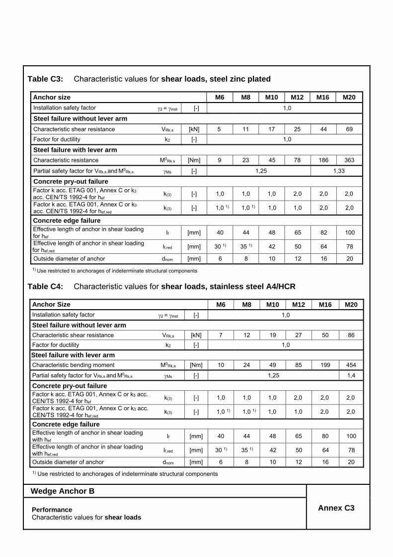
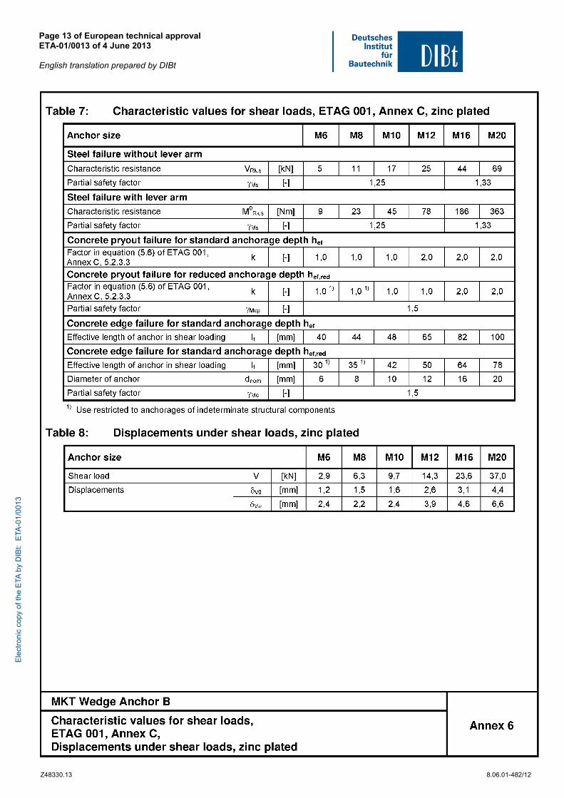
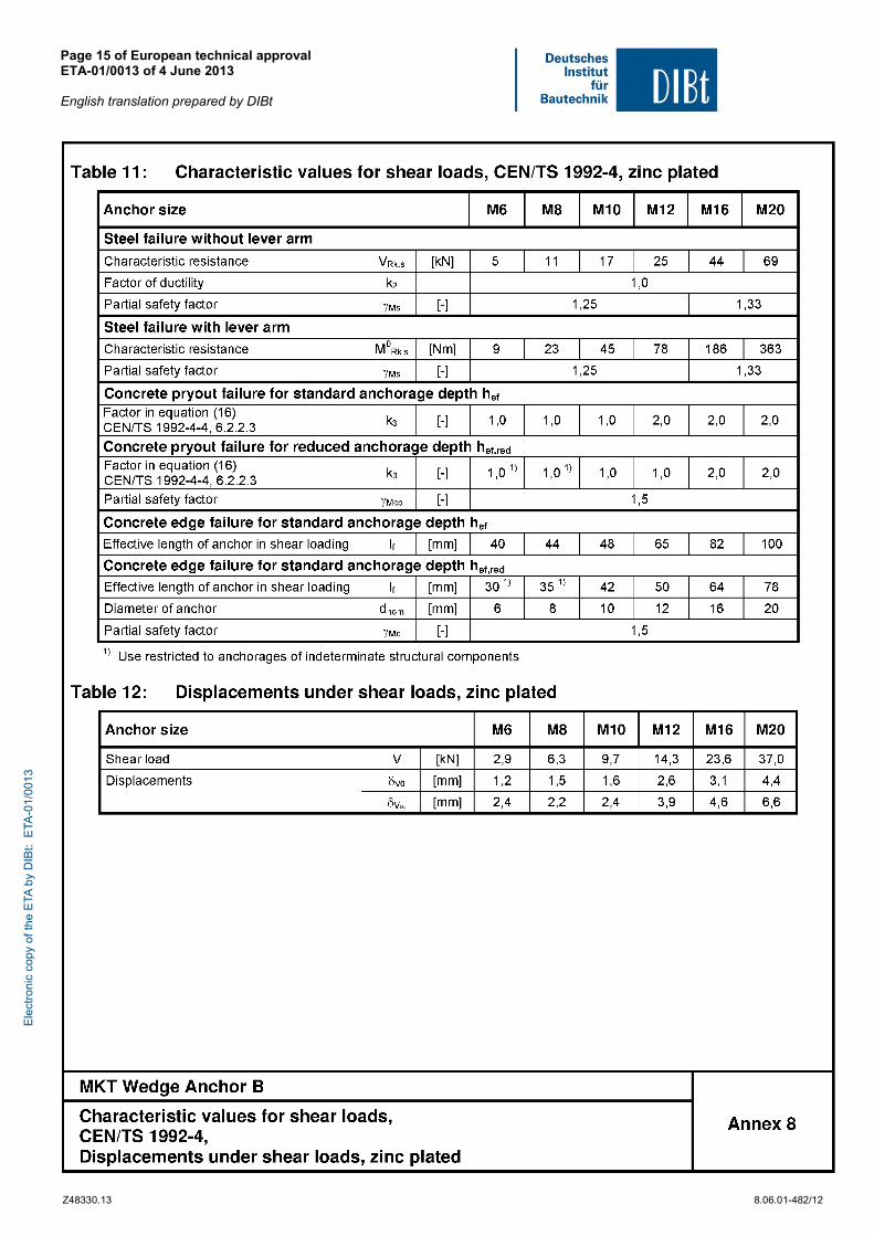
Table C3: Characteristic values for shear loads, steel zinc plated
Anchor size M6 M8 M10 M12 M16 M20
Installation safety factor 2 = inst [-] 1,0
Steel failure without lever arm
Characteristic shear resistance VRk.s [kN] 5 11 17 25 44 69
Factor for ductility k2 [-] 1,0
Steel failure with lever arm Characteristic resistance M0
Rk.s [Nm] 9 23 45 78 186 363
Partial safety factor for VRk,s and M0Rk,s Ms [-] 1,25 1,33
Concrete pry-out failure Factor k acc. ETAG 001, Annex C or k3 acc. CEN/TS 1992-4 for hef
k(3) [-] 1,0 1,0 1,0 2,0 2,0 2,0
Factor k acc. ETAG 001, Annex C or k3 acc. CEN/TS 1992-4 for hef,red
k(3) [-] 1,0 1) 1,0 1) 1,0 1,0 2,0 2,0
Concrete edge failure Effective length of anchor in shear loading for hef
lf [mm] 40 44 48 65 82 100
Effective length of anchor in shear loading for hef,red
lf,red [mm] 30 1) 35 1) 42 50 64 78
Outside diameter of anchor dnom [mm] 6 8 10 12 16 20
1) Use restricted to anchorages of indeterminate structural components
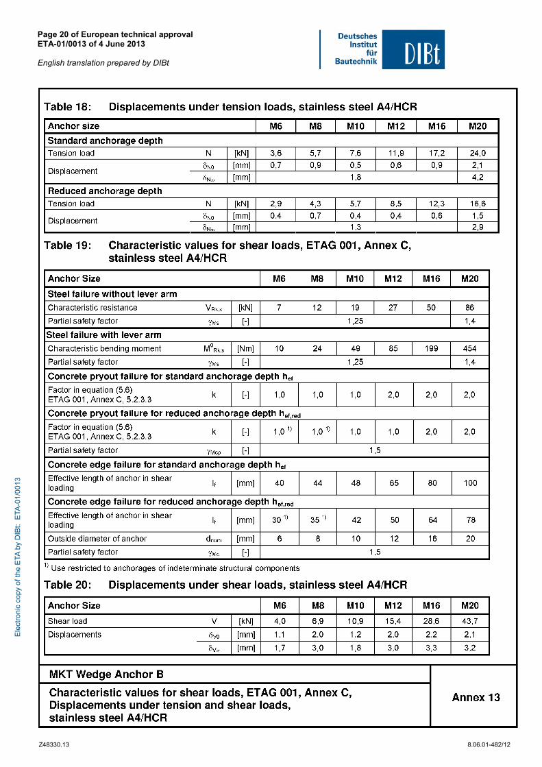
Table C4: Characteristic values for shear loads, stainless steel A4/HCR
Anchor Size M6 M8 M10 M12 M16 M20
Installation safety factor 2 = inst [-] 1,0
Steel failure without lever arm
Characteristic shear resistance VRk,s [kN] 7 12 19 27 50 86
Factor for ductility k2 [-] 1,0
Steel failure with lever arm
Characteristic bending moment M0Rk,s [Nm] 10 24 49 85 199 454
Partial safety factor for VRk,s and M0Rk,s Ms [-] 1,25 1,4
Concrete pry-out failure Factor k acc. ETAG 001, Annex C or k3 acc. CEN/TS 1992-4 for hef
k(3) [-] 1,0 1,0 1,0 2,0 2,0 2,0
Factor k acc. ETAG 001, Annex C or k3 acc. CEN/TS 1992-4 for hef,red
k(3) [-] 1,0 1) 1,0 1) 1,0 1,0 2,0 2,0
Concrete edge failure Effective length of anchor in shear loading with hef
lf [mm] 40 44 48 65 80 100
Effective length of anchor in shear loading with hef,red
lf,red [mm] 30 1) 35 1) 42 50 64 78
Outside diameter of anchor dnom [mm] 6 8 10 12 16 20
1) Use restricted to anchorages of indeterminate structural components
Wedge Anchor B
Annex C3 Performance Characteristic values for shear loads
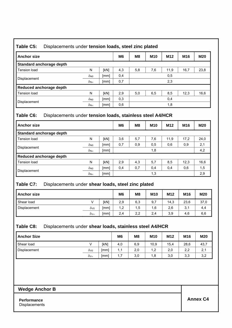
Table C5: Displacements under tension loads, steel zinc plated
Anchor size M6 M8 M10 M12 M16 M20
Standard anchorage depth
Tension load N [kN] 4,3 5,8 7,6 11,9 16,7 23,8
Displacement N0 [mm] 0,4 0,5
N [mm] 0,7 2,3
Reduced anchorage depth
Tension load N [kN] 2,9 5,0 6,5 8,5 12,3 16,6
Displacement N0 [mm] 0,3 0,4
N [mm] 0,6 1,8
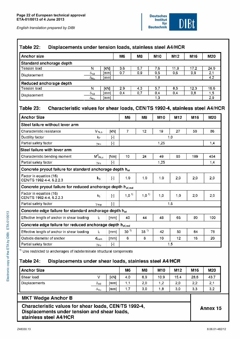
Table C6: Displacements under tension loads, stainless steel A4/HCR
Anchor size M6 M8 M10 M12 M16 M20
Standard anchorage depth
Tension load N [kN] 3,6 5,7 7,6 11,9 17,2 24,0
Displacement N0 [mm] 0,7 0,9 0,5 0,6 0,9 2,1
N [mm] 1,8 4,2
Reduced anchorage depth
Tension load N [kN] 2,9 4,3 5,7 8,5 12,3 16,6
Displacement N0 [mm] 0,4 0,7 0,4 0,4 0,6 1,5
N [mm] 1,3 2,9
Table C7: Displacements under shear loads, steel zinc plated
Anchor size M6 M8 M10 M12 M16 M20
Shear load V [kN] 2,9 6,3 9,7 14,3 23,6 37,0
Displacement V0 [mm] 1,2 1,5 1,6 2,6 3,1 4,4
V [mm] 2,4 2,2 2,4 3,9 4,6 6,6
Table C8: Displacements under shear loads, stainless steel A4/HCR
Anchor Size M6 M8 M10 M12 M16 M20
Shear load V [kN] 4,0 6,9 10,9 15,4 28,6 43,7
Displacement V0 [mm] 1,1 2,0 1,2 2,0 2,2 2,1
V [mm] 1,7 3,0 1,8 3,0 3,3 3,2
Wedge Anchor B
Annex C4 Performance Displacements
... a solid connection 26... a solid connection
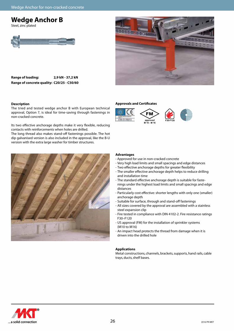
Wedge Anchor for non-cracked concrete
Wedge Anchor BSteel, zinc plated
Range of loading: 2,9 kN - 37,2 kNRange of concrete quality: C20/25 - C50/60
DescriptionThe tried and tested wedge anchor B with European technical approval, Option 7, is ideal for time-saving through fastenings in non-cracked concrete.
Its two e�ective anchorage depths make it very �exible, reducing contacts with reinforcements when holes are drilled.The long thread also makes stand-o� fastenings possible. The hot dip galvanised version is also included in the approval, like the B-U version with the extra large washer for timber structures.
Approvals and Certi�cates
approvedM 10 - M 16
F30-F120
Advantages- Approved for use in non-cracked concrete- Very high load limits and small spacings and edge distances - Two e�ective anchorage depths for greater �exibility- The smaller e�ective anchorage depth helps to reduce drilling
and installation time- The standard e�ective anchorage depth is suitable for faste-
nings under the highest load limits and small spacings and edge distances
- Particularly cost e�ective: shorter lengths with only one (smaller) anchorage depth
- Suitable for surface, through and stand-o� fastenings- All sizes covered by the approval are assembled with a stainless
steel expansion clip- Fire tested in compliance with DIN 4102-2. Fire resistance ratings
F30–F120- US approval (FM) for the installation of sprinkler systems
(M10 to M16)- An impact head protects the thread from damage when it is
driven into the drilled hole
ApplicationsMetal constructions, channels, brackets, supports, hand rails, cabletrays, ducts, shelf bases.
2016 PR MKT
... a solid connection27 ... a solid connection
Mechanical Heavy Duty Anchors
Mec
han
ical
Hea
vy D
uty
An
cho
rs
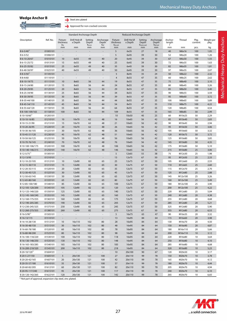
Wedge Anchor B Steel zinc plated
Approved for non-cracked concrete
1) Not part of approval, expansion clip steel, zinc plated.
Mec
han
ical
Hea
vy D
uty
An
cho
rs
Standard Anchorage Depth Reduced Anchorage Depth
Description Ref. No. Fixture-thickness
t�xmm
Drill Hole Ø x Depth
mm
Setting Depthhnommm
Anchorage Depth
hefmm
Fixture-thickness
t�x,redmm
Drill Hol Ø x Depth
mm
Setting Depthhnom,red
mm
Anchorage Depth hef,redmm
Anchor-length
lmm
Thread
mm
Pkg.content
pcs.
Weight per pkg.
kg
B 6-5/401) 01005101 - - - - 5 6x35 27 18 40 M6x16 100 1,05
B 6-5/52 01006101 - - - - 5 6x45 39 30 52 M6x20 100 1,26
B 6-10-20/67 01010101 10 6x55 49 40 20 6x45 39 30 67 M6x30 100 1,55
B 6-15-25/72 01013101 15 6x55 49 40 25 6x45 39 30 72 M6x35 100 1,63
B 6-25-35/82 01015101 25 6x55 49 40 35 6x45 39 30 82 M6x35 100 1,81
B 6-40-50/97 01025101 40 6x55 49 40 50 6x45 39 30 97 M6x35 100 2,07
B 8-5/501) 01105101 - - - - 5 8x45 35 24 50 M8x22 100 2,32
B 8-4/60 01110101 - - - - 4 8x55 47 35 60 M8x25 100 2,62
B 8-10-19/75 01115101 10 8x65 56 44 19 8x55 47 35 75 M8x40 100 3,10
B 8-15-24/80 01120101 15 8x65 56 44 24 8x55 47 35 80 M8x45 100 3,26
B 8-20-29/85 01125101 20 8x65 56 44 29 8x55 47 35 85 M8x50 100 3,40
B 8-25-34/90 01130101 25 8x65 56 44 34 8x55 47 35 90 M8x55 100 3,59
B 8-30-39/95 01135101 30 8x65 56 44 39 8x55 47 35 95 M8x60 100 3,72
B 8-35-44/100 01140101 35 8x65 56 44 44 8x55 47 35 100 M8x65 100 3,89
B 8-45-54/110 01145101 45 8x65 56 44 54 8x55 47 35 110 M8x75 100 4,22
B 8-55-64/120 01150101 55 8x65 56 44 64 8x55 47 35 120 M8x85 100 4,54
B 8-100-109/165 01158101 100 8x65 56 44 109 8x55 47 35 165 M8x85 50 2,99
B 10-10/601) 01205101 - - - - 10 10x50 40 25 60 M10x25 50 2,29
B 10-10-16/85 01210101 10 10x70 62 48 16 10x65 56 42 85 M10x40 50 2,83
B 10-15-21/90 01215101 15 10x70 62 48 21 10x65 56 42 90 M10x45 50 2,94
B 10-20-26/95 01220101 20 10x70 62 48 26 10x65 56 42 95 M10x50 50 3,06
B 10-30-36/105 01225101 30 10x70 62 48 36 10x65 56 42 105 M10x60 50 3,32
B 10-45-51/120 01230101 45 10x70 62 48 51 10x65 56 42 120 M10x75 50 3,72
B 10-50-56/125 01235101 50 10x70 62 48 56 10x65 56 42 125 M10x80 50 3,85
B 10-70-76/145 01240101 70 10x70 62 48 76 10x65 56 42 145 M10x80 50 4,35
B 10-100-106/175 01245101 100 10x70 62 48 106 10x65 56 42 175 M10x80 50 5,10
B 10-140-146/215 01250101 140 10x70 62 48 146 10x65 56 42 215 M10x80 25 3,06
B 12-5/751) 01305101 - - - - 5 12x65 55 38 75 M12x30 25 1,98
B 12-13/95 01310101 - - - - 13 12x75 67 50 95 M12x50 25 2,33
B 12-10-25/105 01312101 10 12x90 82 65 25 12x75 67 50 105 M12x60 25 2,55
B 12-15-30/110 01315101 15 12x90 82 65 30 12x75 67 50 110 M12x65 25 2,60
B 12-20-35/115 01320101 20 12x90 82 65 35 12x75 67 50 115 M12x70 25 2,70
B 12-30-45/125 01325101 30 12x90 82 65 45 12x75 67 50 125 M12x80 25 2,88
B 12-50-65/145 01330101 50 12x90 82 65 65 12x75 67 50 145 M12x100 25 3,26
B 12-65-80/160 01335101 65 12x90 82 65 80 12x75 67 50 160 M12x100 25 3,49
B 12-85-100/180 01340101 85 12x90 82 65 100 12x75 67 50 180 M12x100 25 3,90
B 12-105-120/200 01345101 105 12x90 82 65 120 12x75 67 50 200 M12x100 25 4,22
B 12-125-140/220 01350101 125 12x90 82 65 140 12x75 67 50 220 M12x80 25 5,04
B 12-145-160/240 01355101 145 12x90 82 65 160 12x75 67 50 240 M12x80 20 4,38
B 12-160-175/255 01365101 160 12x90 82 65 175 12x75 67 50 255 M12x80 20 4,68
B 12-190-205/285 01370101 190 12x90 82 65 205 12x75 67 50 285 M12x80 20 5,21
B 12-230-245/325 01375101 230 12x90 82 65 245 12x75 67 50 325 M12x80 20 5,90
B 12-260-275/355 01380101 260 12x90 82 65 275 12x75 67 50 355 M12x80 20 6,53
B 16-5/901) 01505101 - - - - 5 16x75 65 47 90 M16x35 20 3,32
B 16-13/115 01510101 - - - - 13 16x95 84 64 115 M16x60 20 3,98
B 16-10-28/130 01512101 10 16x110 102 80 28 16x95 84 64 130 M16x70 20 4,50
B 16-30-48/150 01515101 30 16x110 102 80 48 16x95 84 64 150 M16x90 20 4,87
B 16-60-78/180 01520101 60 16x110 102 80 78 16x95 84 64 180 M16x110 20 5,66
B 16-80-98/200 01525101 80 16x110 102 80 98 16x95 84 64 200 M16x110 10 3,12
B 16-100-118/220 01530101 100 16x110 102 80 118 16x95 84 64 220 M16x80 10 3,64
B 16-130-148/250 01535101 130 16x110 102 80 148 16x95 84 64 250 M16x80 10 4,10
B 16-165-183/285 01540101 165 16x110 102 80 183 16x95 84 64 285 M16x80 10 4,68
B 16-200-218/320 01545101 200 16x110 102 80 218 16x95 84 64 320 M16x80 10 5,23
B 20-10/1201) 01604101 - - - - 10 20x100 90 67 120 M20x50 10 3,17
B 20-5-27/150 01605101 5 20x130 121 100 27 20x110 99 78 150 M20x70 10 3,78
B 20-20-42/165 01607101 20 20x130 121 100 42 20x110 99 78 165 M20x70 10 4,12
B 20-35-57/180 01610101 35 20x130 121 100 57 20x110 99 78 180 M20x70 10 4,44
B 20-60-82/205 01612101 60 20x130 121 100 82 20x110 99 78 205 M20x70 10 4,94
B 20-95-117/240 01615101 95 20x130 121 100 117 20x110 99 78 240 M20x70 10 6,10
B 20-120-142/265 01622101 120 20x130 121 100 142 20x110 99 78 265 M20x70 10 6,65
2016 PR MKT
... a solid connection 28... a solid connection
Wedge Anchor for non-cracked concrete
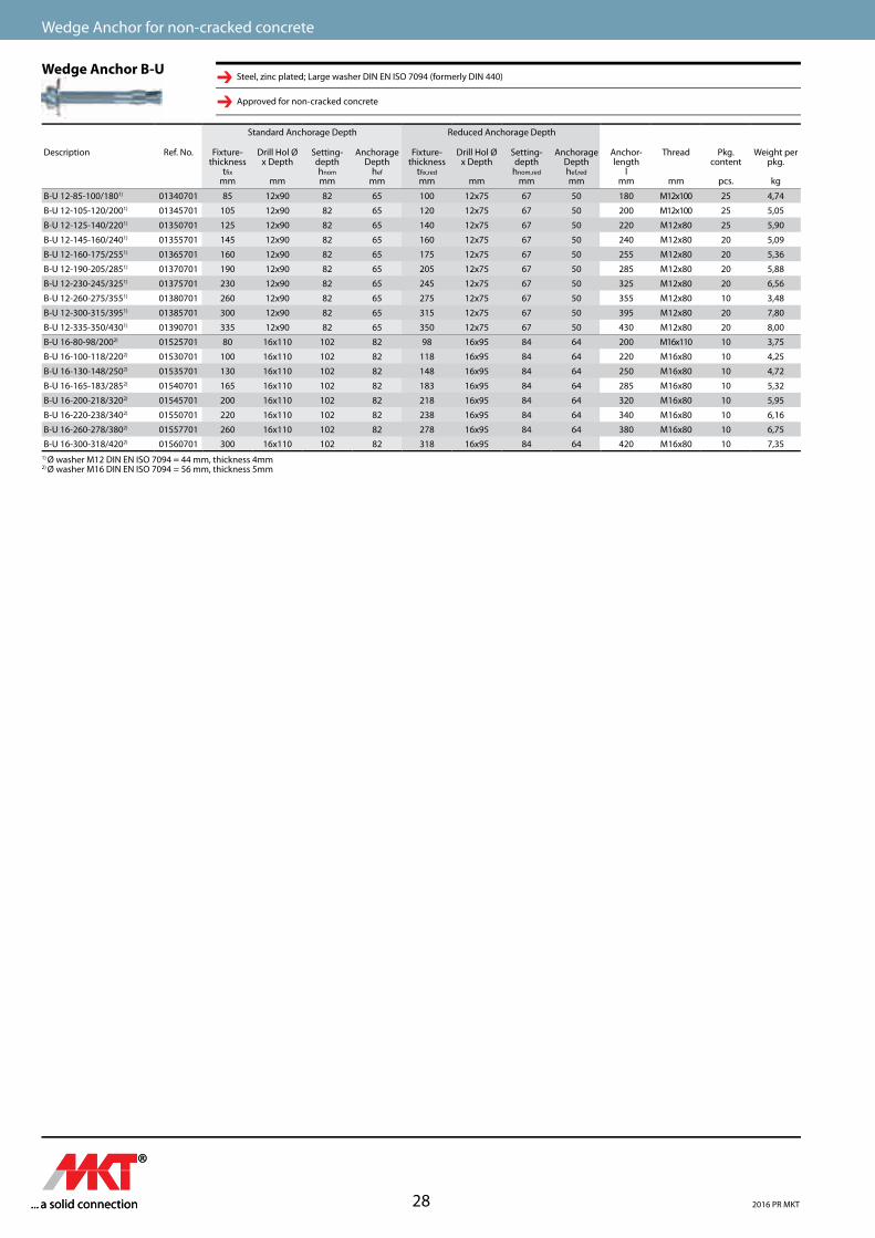
Wedge Anchor B-USteel, zinc plated; Large washer DIN EN ISO 7094 (formerly DIN 440)
Approved for non-cracked concrete
1) Ø washer M12 DIN EN ISO 7094 = 44 mm, thickness 4mm2) Ø washer M16 DIN EN ISO 7094 = 56 mm, thickness 5mm
Standard Anchorage Depth Reduced Anchorage Depth
Description Ref. No. Fixture-thickness
t�xmm
Drill Hol Ø x Depth
mm
Setting-depthhnommm
Anchorage Depth
hefmm
Fixture-thickness
t�x,redmm
Drill Hol Ø x Depth
mm
Setting-depth
hnom,redmm
Anchorage Depth hef,redmm
Anchor-length
lmm
Thread
mm
Pkg.content
pcs.
Weight per pkg.
kg
B-U 12-85-100/1801) 01340701 85 12x90 82 65 100 12x75 67 50 180 M12x100 25 4,74
B-U 12-105-120/2001) 01345701 105 12x90 82 65 120 12x75 67 50 200 M12x100 25 5,05
B-U 12-125-140/2201) 01350701 125 12x90 82 65 140 12x75 67 50 220 M12x80 25 5,90
B-U 12-145-160/2401) 01355701 145 12x90 82 65 160 12x75 67 50 240 M12x80 20 5,09
B-U 12-160-175/2551) 01365701 160 12x90 82 65 175 12x75 67 50 255 M12x80 20 5,36
B-U 12-190-205/2851) 01370701 190 12x90 82 65 205 12x75 67 50 285 M12x80 20 5,88
B-U 12-230-245/3251) 01375701 230 12x90 82 65 245 12x75 67 50 325 M12x80 20 6,56
B-U 12-260-275/3551) 01380701 260 12x90 82 65 275 12x75 67 50 355 M12x80 10 3,48
B-U 12-300-315/3951) 01385701 300 12x90 82 65 315 12x75 67 50 395 M12x80 20 7,80
B-U 12-335-350/4301) 01390701 335 12x90 82 65 350 12x75 67 50 430 M12x80 20 8,00
B-U 16-80-98/2002) 01525701 80 16x110 102 82 98 16x95 84 64 200 M16x110 10 3,75
B-U 16-100-118/2202) 01530701 100 16x110 102 82 118 16x95 84 64 220 M16x80 10 4,25
B-U 16-130-148/2502) 01535701 130 16x110 102 82 148 16x95 84 64 250 M16x80 10 4,72
B-U 16-165-183/2852) 01540701 165 16x110 102 82 183 16x95 84 64 285 M16x80 10 5,32
B-U 16-200-218/3202) 01545701 200 16x110 102 82 218 16x95 84 64 320 M16x80 10 5,95
B-U 16-220-238/3402) 01550701 220 16x110 102 82 238 16x95 84 64 340 M16x80 10 6,16
B-U 16-260-278/3802) 01557701 260 16x110 102 82 278 16x95 84 64 380 M16x80 10 6,75
B-U 16-300-318/4202) 01560701 300 16x110 102 82 318 16x95 84 64 420 M16x80 10 7,35
2016 PR MKT
... a solid connection29 ... a solid connection
Mechanical Heavy Duty Anchors
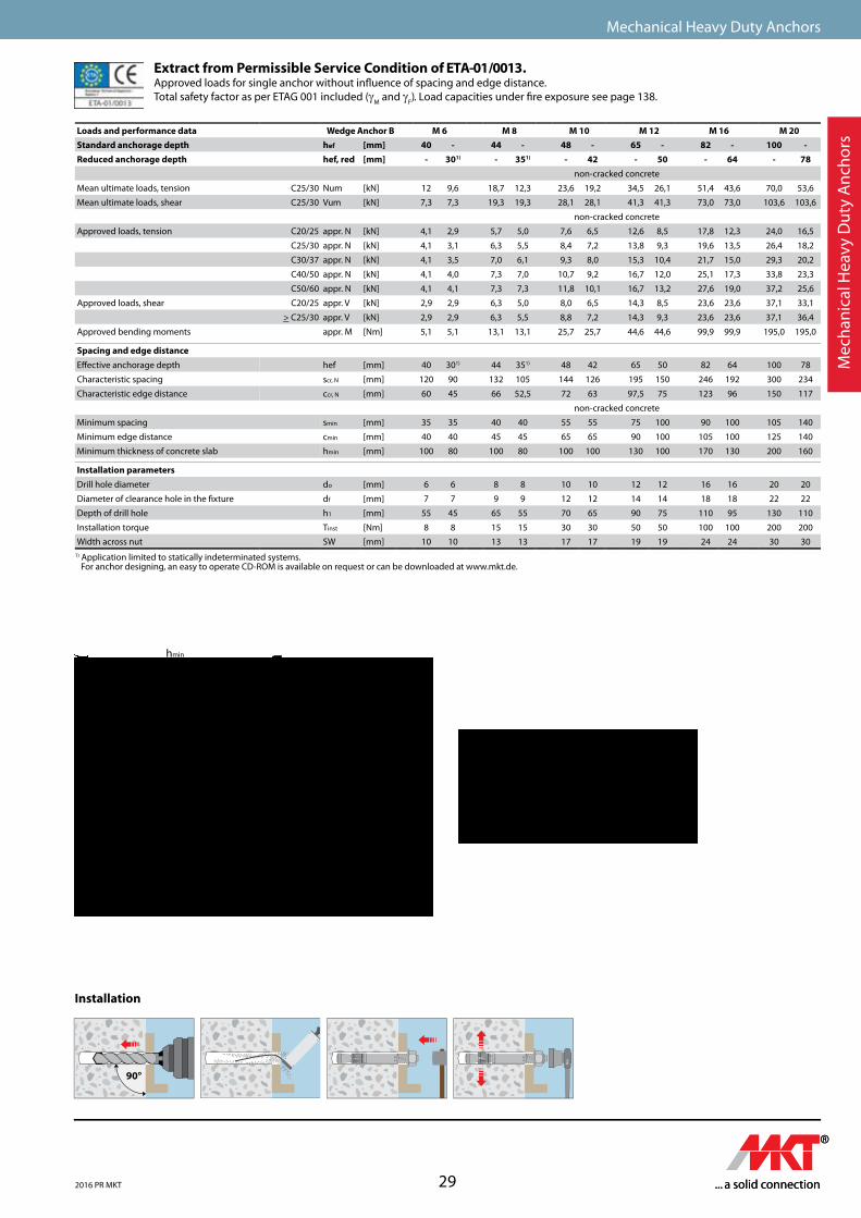
1) Application limited to statically indeterminated systems. For anchor designing, an easy to operate CD-ROM is available on request or can be downloaded at www.mkt.de.
Extract from Permissible Service Condition of ETA-01/0013.Approved loads for single anchor without influence of spacing and edge distance. Total safety factor as per ETAG 001 included (γ
M and γ
F). Load capacities under fire exposure see page 138.
Loads and performance data Wedge Anchor B M 6 M 8 M 10 M 12 M 16 M 20Standard anchorage depth hef [mm] 40 - 44 - 48 - 65 - 82 - 100 -Reduced anchorage depth hef, red [mm] - 301) - 351) - 42 - 50 - 64 - 78
non-cracked concrete
Mean ultimate loads, tension C25/30 Num [kN] 12 9,6 18,7 12,3 23,6 19,2 34,5 26,1 51,4 43,6 70,0 53,6
Mean ultimate loads, shear C25/30 Vum [kN] 7,3 7,3 19,3 19,3 28,1 28,1 41,3 41,3 73,0 73,0 103,6 103,6
non-cracked concrete
Approved loads, tension C20/25 appr. N [kN] 4,1 2,9 5,7 5,0 7,6 6,5 12,6 8,5 17,8 12,3 24,0 16,5
C25/30 appr. N [kN] 4,1 3,1 6,3 5,5 8,4 7,2 13,8 9,3 19,6 13,5 26,4 18,2
C30/37 appr. N [kN] 4,1 3,5 7,0 6,1 9,3 8,0 15,3 10,4 21,7 15,0 29,3 20,2
C40/50 appr. N [kN] 4,1 4,0 7,3 7,0 10,7 9,2 16,7 12,0 25,1 17,3 33,8 23,3
C50/60 appr. N [kN] 4,1 4,1 7,3 7,3 11,8 10,1 16,7 13,2 27,6 19,0 37,2 25,6
Approved loads, shear C20/25 appr. V [kN] 2,9 2,9 6,3 5,0 8,0 6,5 14,3 8,5 23,6 23,6 37,1 33,1
> C25/30 appr. V [kN] 2,9 2,9 6,3 5,5 8,8 7,2 14,3 9,3 23,6 23,6 37,1 36,4
Approved bending moments appr. M [Nm] 5,1 5,1 13,1 13,1 25,7 25,7 44,6 44,6 99,9 99,9 195,0 195,0
Spacing and edge distanceE�ective anchorage depth hef [mm] 40 301) 44 351) 48 42 65 50 82 64 100 78
Characteristic spacing scr, N [mm] 120 90 132 105 144 126 195 150 246 192 300 234
Characteristic edge distance ccr, N [mm] 60 45 66 52,5 72 63 97,5 75 123 96 150 117
non-cracked concrete
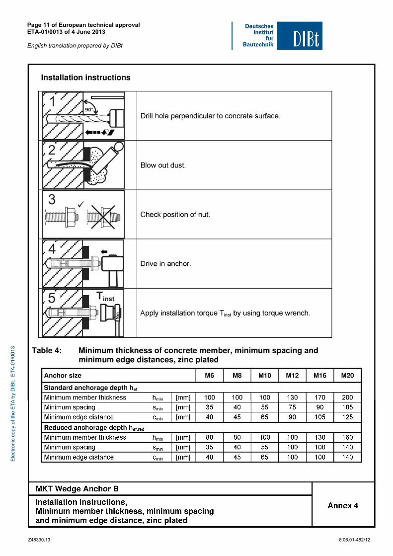
Minimum spacing smin [mm] 35 35 40 40 55 55 75 100 90 100 105 140
Minimum edge distance cmin [mm] 40 40 45 45 65 65 90 100 105 100 125 140
Minimum thickness of concrete slab hmin [mm] 100 80 100 80 100 100 130 100 170 130 200 160
Installation parametersDrill hole diameter do [mm] 6 6 8 8 10 10 12 12 16 16 20 20
Diameter of clearance hole in the �xture df [mm] 7 7 9 9 12 12 14 14 18 18 22 22
Depth of drill hole h1 [mm] 55 45 65 55 70 65 90 75 110 95 130 110
Installation torque Tinst [Nm] 8 8 15 15 30 30 50 50 100 100 200 200
Width across nut SW [mm] 10 10 13 13 17 17 19 19 24 24 30 30
Installation
hmin
h1
hef tfix
hef,red
h1,red
hmin
tfix
Tinst
Tinst
hnom,red
hnom
Mec
han
ical
Hea
vy D
uty
An
cho
rs
B M8-2
Nm
90°
M8-2
B
2016 PR MKT
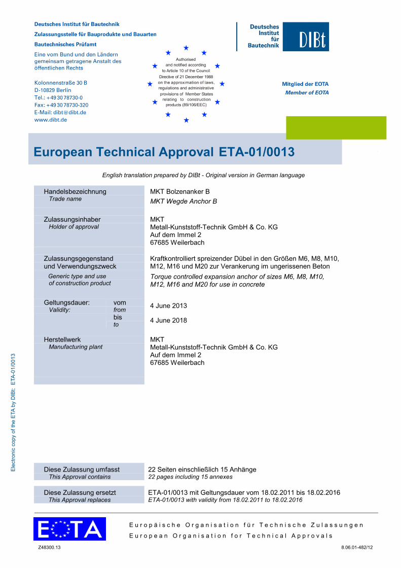
Diese Zulassung umfasst
This Approval contains
22 Seiten einschließlich 15 Anhänge 22 pages including 15 annexes
Diese Zulassung ersetzt This Approval replaces
ETA-01/0013 mit Geltungsdauer vom 18.02.2011 bis 18.02.2016 ETA-01/0013 with validity from 18.02.2011 to 18.02.2016
E u r o p ä i s c h e O r g a n i s a t i o n f ü r T e c h n i s c h e Z u l a s s u n g e n
E u r o p e a n O r g a n i s a t i o n f o r T e c h n i c a l A p p r o v a l s
Z48300.13 8.06.01-482/12
English translation prepared by DIBt - Original version in German language
Handelsbezeichnung Trade name
MKT Bolzenanker B
MKT Wegde Anchor B
Zulassungsinhaber
Holder of approval MKT Metall-Kunststoff-Technik GmbH & Co. KG Auf dem Immel 2 67685 Weilerbach
Zulassungsgegenstand und Verwendungszweck
Kraftkontrolliert spreizender Dübel in den Größen M6, M8, M10, M12, M16 und M20 zur Verankerung im ungerissenen Beton
Generic type and use of construction product
Torque controlled expansion anchor of sizes M6, M8, M10, M12, M16 and M20 for use in concrete
Geltungsdauer:
Validity: vom from
4 June 2013
bis to
4 June 2018
Herstellwerk
Manufacturing plant MKT Metall-Kunststoff-Technik GmbH & Co. KG Auf dem Immel 2 67685 Weilerbach
European Technical Approval ETA-01/0013
Ele
ctro
nic
copy
of t
he E
TA b
y D
IBt:
ETA
-01/
0013
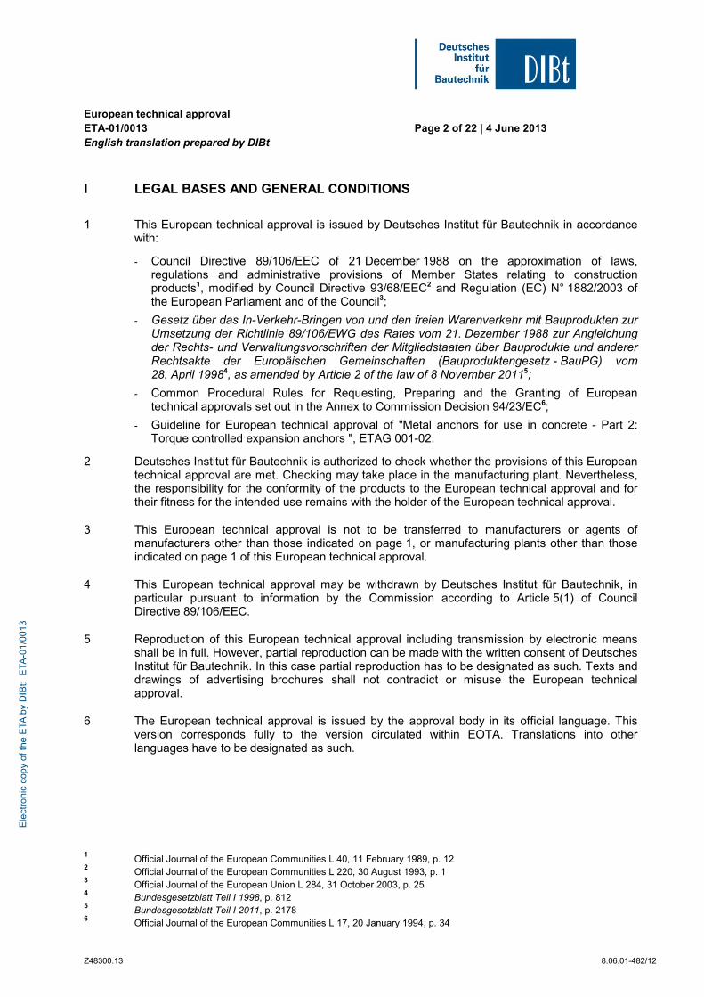
European technical approval ETA-01/0013 English translation prepared by DIBt
Page 2 of 22 | 4 June 2013
Z48300.13 8.06.01-482/12
I LEGAL BASES AND GENERAL CONDITIONS
1 This European technical approval is issued by Deutsches Institut für Bautechnik in accordance with:
- Council Directive 89/106/EEC of 21 December 1988 on the approximation of laws, regulations and administrative provisions of Member States relating to construction products1, modified by Council Directive 93/68/EEC2 and Regulation (EC) N° 1882/2003 of the European Parliament and of the Council3;
- Gesetz über das In-Verkehr-Bringen von und den freien Warenverkehr mit Bauprodukten zur Umsetzung der Richtlinie 89/106/EWG des Rates vom 21. Dezember 1988 zur Angleichung der Rechts- und Verwaltungsvorschriften der Mitgliedstaaten über Bauprodukte und anderer Rechtsakte der Europäischen Gemeinschaften (Bauproduktengesetz - BauPG) vom 28. April 19984, as amended by Article 2 of the law of 8 November 20115;
- Common Procedural Rules for Requesting, Preparing and the Granting of European technical approvals set out in the Annex to Commission Decision 94/23/EC6;
- Guideline for European technical approval of "Metal anchors for use in concrete - Part 2: Torque controlled expansion anchors ", ETAG 001-02.
2 Deutsches Institut für Bautechnik is authorized to check whether the provisions of this European technical approval are met. Checking may take place in the manufacturing plant. Nevertheless, the responsibility for the conformity of the products to the European technical approval and for their fitness for the intended use remains with the holder of the European technical approval.
3 This European technical approval is not to be transferred to manufacturers or agents of manufacturers other than those indicated on page 1, or manufacturing plants other than those indicated on page 1 of this European technical approval.
4 This European technical approval may be withdrawn by Deutsches Institut für Bautechnik, in particular pursuant to information by the Commission according to Article 5(1) of Council Directive 89/106/EEC.
5 Reproduction of this European technical approval including transmission by electronic means shall be in full. However, partial reproduction can be made with the written consent of Deutsches Institut für Bautechnik. In this case partial reproduction has to be designated as such. Texts and drawings of advertising brochures shall not contradict or misuse the European technical approval.
6 The European technical approval is issued by the approval body in its official language. This version corresponds fully to the version circulated within EOTA. Translations into other languages have to be designated as such.
1 Official Journal of the European Communities L 40, 11 February 1989, p. 12
2 Official Journal of the European Communities L 220, 30 August 1993, p. 1
3 Official Journal of the European Union L 284, 31 October 2003, p. 25
4 Bundesgesetzblatt Teil I 1998, p. 812
5 Bundesgesetzblatt Teil I 2011, p. 2178
6 Official Journal of the European Communities L 17, 20 January 1994, p. 34
Ele
ctro
nic
copy
of t
he E
TA b
y D
IBt:
ETA
-01/
0013
European technical approval ETA-01/0013 English translation prepared by DIBt
Page 3 of 22 | 4 June 2013
Z48300.13 8.06.01-482/12
II SPECIFIC CONDITIONS OF THE EUROPEAN TECHNICAL APPROVAL
1 Definition of product and intended use
1.1 Definition of the construction product
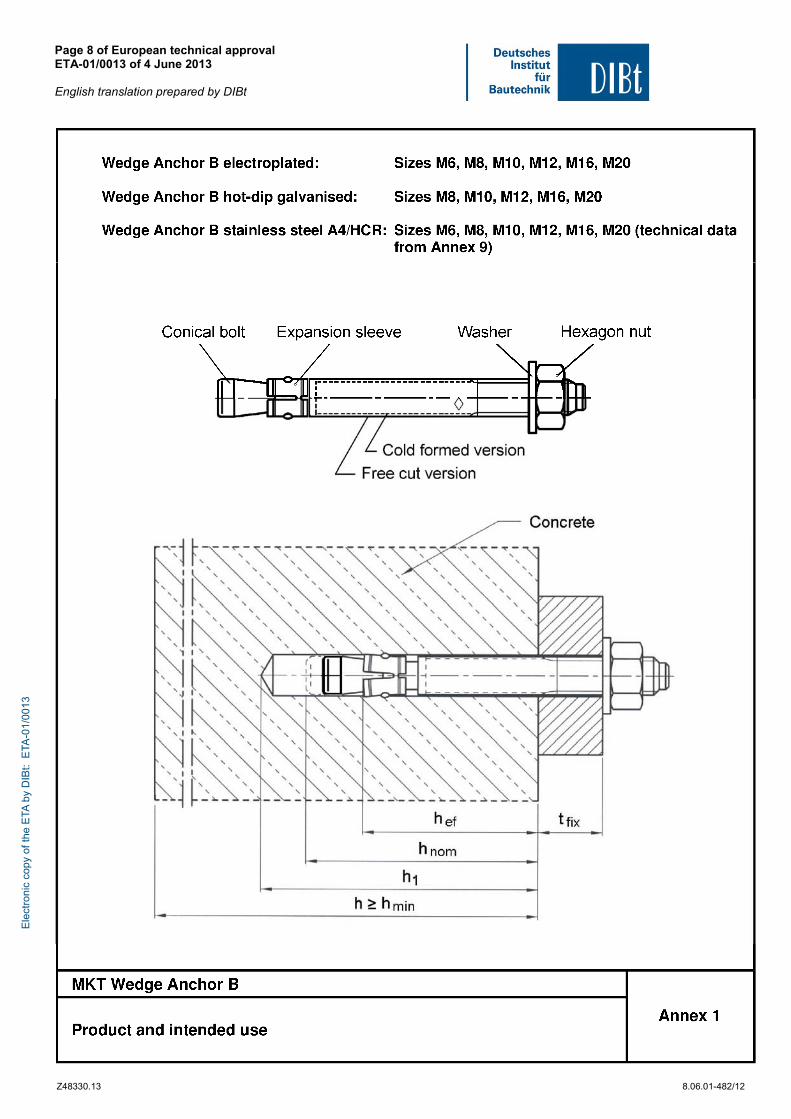
The MKT Wedge Anchor B in the range of M6, M8, M10, M12, M16 and M20 is an anchor made of electroplated, hot dipped galvanised steel, stainless steel or high corrosions resistant steel which is placed into a drilled hole and anchored by torque-controlled expansion.
An illustration of the product and intended use is given in Annex 1.
1.2 Intended use
The anchor is intended to be used for anchorages for which requirements for mechanical resistance and stability and safety in use in the sense of the Essential Requirements 1 and 4 of Council Directive 89/106 EEC shall be fulfilled and failure of anchorages made with these products would cause risk to human life and/or lead to considerable economic consequences. The anchor is to be used only for anchorages subject to static or quasi-static loading in reinforced or unreinforced normal weight concrete of strength classes C20/25 at minimum and C50/60 at most according to EN 206:2000-12.
It may be anchored in non-cracked concrete only.
Anchor made of galvanised or hot-dip galvanised steel:
The MKT Wedge Anchor B made of galvanised or hot-dip galvanised steel may only be used in structures subject to dry internal conditions.
Anchor made of stainless steel
The MKT Wedge anchor B A4 may be used in structures subject to dry internal conditions and also in structures subject to external atmospheric exposure (including industrial and marine environment), or exposure in permanently damp internal conditions, if no particular aggressive conditions exist. Such particular aggressive conditions are e.g. permanent, alternating immersion in seawater or the splash zone of seawater, chloride atmosphere of indoor swimming pools or atmosphere with extreme chemical pollution (e. g. in desulphurization plants or road tunnels where de-icing materials are used).
Anchor made of high corrosion resistant steel
The MKT Wedge anchor B HCR may be used in structures subject to dry internal conditions and also in structures subject to external atmospheric exposure, in permanently damp internal conditions or in other particular aggressive conditions. Such particular aggressive conditions are e.g. permanent, alternating immersion in seawater or the splash zone of seawater, chloride atmosphere of indoor swimming pools or atmosphere with chemical pollution (e.g. in desulphurization plants or road tunnels where de-icing materials are used).
The provisions made in this European technical approval are based on an assumed working life of the anchor of 50 years. The indications given on the working life cannot be interpreted as a guarantee given by the producer, but are to be regarded only as a means for choosing the right products in relation to the expected economically reasonable working life of the works.
Ele
ctro
nic
copy
of t
he E
TA b
y D
IBt:
ETA
-01/
0013
European technical approval ETA-01/0013 English translation prepared by DIBt
Page 4 of 22 | 4 June 2013
Z48300.13 8.06.01-482/12
2 Characteristics of the product and methods of verification
2.1 Characteristics of the product
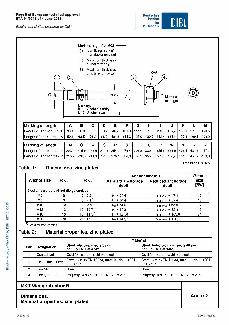
The anchor corresponds to the drawings and provisions given in the Annexes. The characteristic material values, dimensions and tolerances of the anchor not given in the Annexes shall correspond to the respective values laid down in the technical documentation7 of this European technical approval.
The characteristic values for the design of anchorages are given in the Annexes.
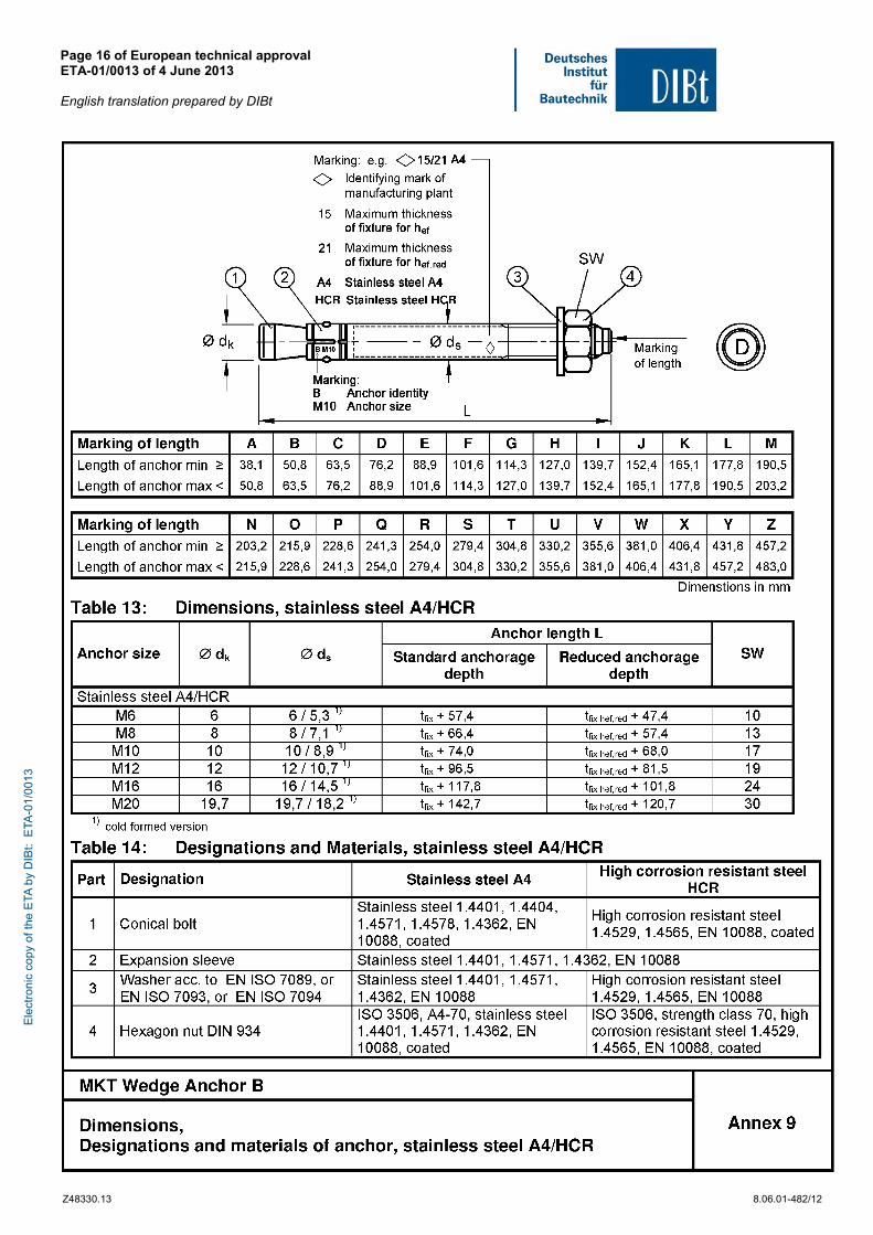
Each anchor is marked with the identifying mark of the manufacturing plant, the anchor identity, the anchor size and the maximum thickness of fixture for hef and hef,red according to Annex 2 and 9.
The anchor shall only be packaged and supplied as a complete unit.
2.2 Methods of verification
The assessment of fitness of the anchor for the intended use in relation to the requirements for mechanical resistance and stability and safety in use in the sense of the Essential Requirements 1 and 4 has been made in accordance with the "Guideline for European technical approval of Metal Anchors for Use in Concrete", Part 1 "Anchors in general" and Part 2 "Torque-controlled expansion anchors", on the basis of Option 7.
In addition to the specific clauses relating to dangerous substances contained in this European technical approval, there may be other requirements applicable to the products falling within its scope (e.g. transposed European legislation and national laws, regulations and administrative provisions). In order to meet the provisions of the Construction Products Directive, these requirements need also to be complied with, when and where they apply.
3 Evaluation and attestation of conformity and CE marking
3.1 System of attestation of conformity
According to the Decision 96/582/EG of the European Commission8 system 2(i) (referred to as system 1) of the attestation of conformity applies.
This system of attestation of conformity is defined as follows:
System 1: Certification of the conformity of the product by an approved certification body on the basis of:
(a) Tasks for the manufacturer:
(1) factory production control; (2) further testing of samples taken at the factory by the manufacturer in accordance
with a prescribed control plan; (b) Tasks for the approved body:
(3) initial type-testing of the product; (4) initial inspection of factory and of factory production control; (5) continuous surveillance, assessment and approval of factory production control.
Note: Approved bodies are also referred to as "notified bodies".
7 The technical documentation of this European technical approval is deposited at the Deutsches Institut für Bautechnik
and, as far as relevant for the tasks of the approved bodies involved in the attestation of conformity procedure, is handed over to the approved bodies.
8 Official Journal of the European Communities L 254 of 08.10.1996
Ele
ctro
nic
copy
of t
he E
TA b
y D
IBt:
ETA
-01/
0013
European technical approval ETA-01/0013 English translation prepared by DIBt
Page 5 of 22 | 4 June 2013
Z48300.13 8.06.01-482/12
3.2 Responsibilities
3.2.1 Tasks for the manufacturer
3.2.1.1 Factory production control
The manufacturer shall exercise permanent internal control of production. All the elements, requirements and provisions adopted by the manufacturer shall be documented in a systematic manner in the form of written policies and procedures, including records of results performed. This production control system shall insure that the product is in conformity with this European technical approval.
The manufacturer may only use initial / raw / constituent materials stated in the technical documentation of this European technical approval.
The factory production control shall be in accordance with the control plan which is part of the technical documentation of this European technical approval. The control plan is laid down in the context of the factory production control system operated by the manufacturer and deposited with Deutsches Institut für Bautechnik.9
The results of factory production control shall be recorded and evaluated in accordance with the provisions of the control plan.
3.2.1.2 Other tasks of manufacturer
The manufacturer shall, on the basis of a contract, involve a body which is approved for the tasks referred to in section 3.1 in the field of in order to undertake the actions laid down in section 3.2.2 For this purpose, the control plan referred to in sections 3.2.1.1 and 3.2.2 shall be handed over by the manufacturer to the approved body involved.
The manufacturer shall make a declaration of conformity, stating that the construction product is in conformity with the provisions of this European technical approval.
3.2.2 Tasks for the approved bodies
The approved body shall perform the
- initial type-testing of the product,
- initial inspection of factory and of factory production control,
- continuous surveillance, assessment and approval of factory production control,
in accordance with the provisions laid down in the control plan.
The approved body shall retain the essential points of its actions referred to above and state the results obtained and conclusions drawn in a written report.
The approved certification body involved by the manufacturer shall issue an EC certificate of conformity of the product stating the conformity with the provisions of this European technical approval.
In cases where the provisions of the European technical approval and its control plan are no longer fulfilled the certification body shall withdraw the certificate of conformity and inform Deutsches Institut für Bautechnik without delay.
3.3 CE marking
The CE marking shall be affixed on each packaging of the anchor. The letters "CE" shall be followed by the identification number of the approved certification body, where relevant, and be accompanied by the following additional information:
- the name and address of the Producer (legal entity responsible for the manufacturer),
- the last two digits of the year in which the CE marking was affixed,
9 The control plan is a confidential part of the European technical approval and only handed over to the approved body
involved in the procedure of attestation of conformity. See section 3.2.2.
Ele
ctro
nic
copy
of t
he E
TA b
y D
IBt:
ETA
-01/
0013
European technical approval ETA-01/0013 English translation prepared by DIBt
Page 6 of 22 | 4 June 2013
Z48300.13 8.06.01-482/12
- the number of the EC certificate of conformity for the product,
- the number of the European technical approval,
- the number of the guideline for European technical approval,
- use category (ETAG 001-1 Option 7),
- size.
4 Assumptions under which the fitness of the product for the intended use was favourably assessed
4.1 Manufacturing
The European technical approval is issued for the product on the basis of agreed data/information, deposited with the Deutsches Institut für Bautechnik, which identifies the product that has been assessed and judged. Changes to the product or production process, which could result in this deposited data/information being incorrect, should be notified to the Deutsches Institut für Bautechnik before the changes are introduced. Deutsches Institut für Bautechnik will decide whether or not such changes affect the approval and consequently the validity of the CE marking on the basis of the approval and if so whether further assessment or alterations to the approval shall be necessary.
4.2 Design of anchorages
The fitness of the anchor for the intended use is given under the following conditions:
The anchorages are designed either in accordance with
- ETAG 001 "Guideline for European technical approval of Metal Anchors for use in concrete", Annex C, method A
or in accordance with
- CEN/TS 1992-4:2009, design method A under the responsibility of an engineer experienced in anchorages and concrete work.
Verifiable calculation notes and drawings are taking account of the loads to be anchored.
The position of the anchor is indicated on the design drawings (e.g. position of the anchor relative to reinforcement or to supports).
4.3 Installation of anchors
The fitness for use of the anchor can only be assumed if the anchor is installed as follows:
- Anchor installation carried out by appropriately qualified personnel and under the supervision of the person responsible for technical matters of the site,
- Use of the anchor only as supplied by the manufacturer without exchanging the components of an anchor,
- Anchor installation in accordance with the manufacturer’s specifications and drawings and using the appropriate tools,
- Checks before placing the anchor to ensure that the strength class of the concrete in which the anchor is to be placed is in the range given and is not lower than that of the concrete to which the characteristic loads apply,
- Check of concrete being well compacted, e.g. without significant voids,
- Edge distances and spacing not less than the specified values without minus tolerances,
- Positioning of the drill holes without damaging the reinforcement,
Ele
ctro
nic
copy
of t
he E
TA b
y D
IBt:
ETA
-01/
0013
European technical approval ETA-01/0013 English translation prepared by DIBt
Page 7 of 22 | 4 June 2013
Z48300.13 8.06.01-482/12
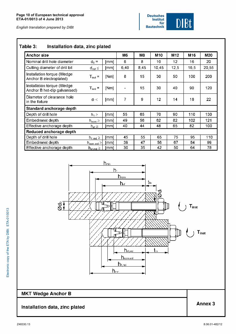
- In case of aborted hole: new drilling at a minimum distance away of twice the depth of the aborted hole or smaller distance if the aborted drill hole is filled with high strength mortar and if under shear or oblique tension load it is not in the direction of load application,
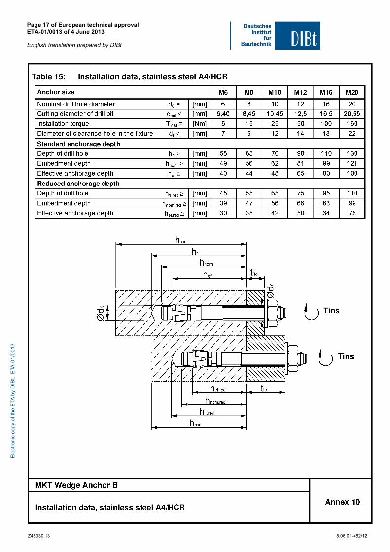
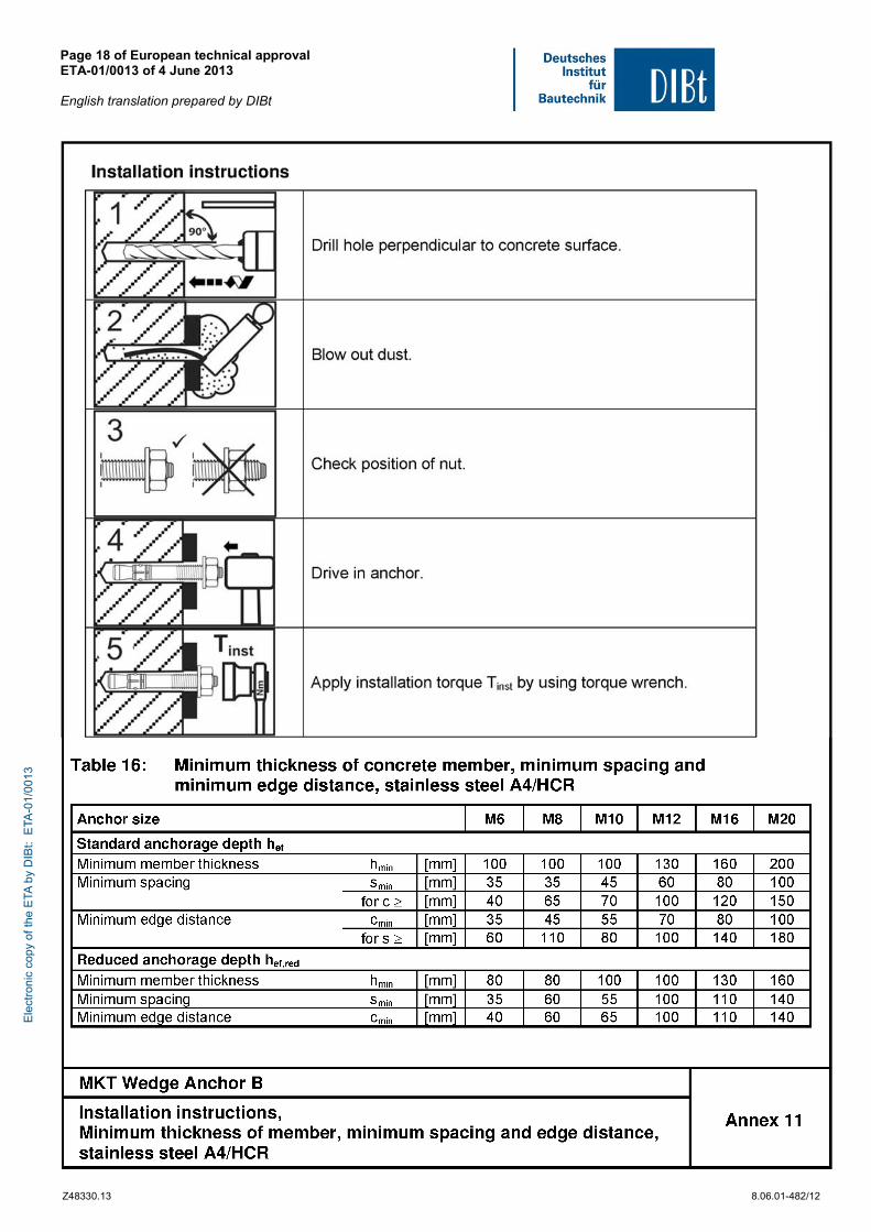
- Cleaning of the hole of drilling dust in accordance with Annex 4 and 11,
- Anchor installation such that the effective anchorage depth is complied with. This compliance is ensured, if the thickness of fixture is not greater than the maximum thickness of fixture marked on the anchor in accordance with Annex 2 and 9 and the hexagon nut is placed at the end of the conical bolt as delivered by the manufacturer,
- Application of the torque moment given in Annex 3 and 10 using a calibrated torque wrench.
5 Responsibility of the manufacturer
The manufacturer is responsible to ensure that the information on the specific conditions according to 1 and 2 including Annexes referred to as well as sections 4.2 and 4.3 is given to those who are concerned. This information may be made by reproduction of the respective parts of the European technical approval. In addition all installation data shall be shown clearly on the package and/or on an enclosed instruction sheet, preferably using illustration(s).
The minimum data required are:
- Diameter of drill bit,
- Thread diameter,
- Maximum thickness of the fixture,
- Minimum effective anchorage depth,
- Minimum hole depth,
- Torque moment,
- Information on the installation procedure, including cleaning of the hole, preferably by means of an illustration,
- Reference to any special installation equipment needed,
- Identification of the manufacturing batch.
All data shall be presented in a clear and explicit form.
Andreas Kummerow beglaubigt:
p.p. Head of Department Baderschneider
Ele
ctro
nic
copy
of t
he E
TA b
y D
IBt:
ETA
-01/
0013
Page 8 of European technical approval ETA-01/0013 of 4 June 2013 English translation prepared by DIBt
Z48330.13 8.06.01-482/12
Ele
ctro
nic
copy
of t
he E
TA b
y D
IBt:
ETA
-01/
0013
Page 9 of European technical approval ETA-01/0013 of 4 June 2013 English translation prepared by DIBt
Z48330.13 8.06.01-482/12
Ele
ctro
nic
copy
of t
he E
TA b
y D
IBt:
ETA
-01/
0013
Page 10 of European technical approval ETA-01/0013 of 4 June 2013 English translation prepared by DIBt
Z48330.13 8.06.01-482/12
Ele
ctro
nic
copy
of t
he E
TA b
y D
IBt:
ETA
-01/
0013
Page 11 of European technical approval ETA-01/0013 of 4 June 2013 English translation prepared by DIBt
Z48330.13 8.06.01-482/12
Ele
ctro
nic
copy
of t
he E
TA b
y D
IBt:
ETA
-01/
0013
Page 12 of European technical approval ETA-01/0013 of 4 June 2013 English translation prepared by DIBt
Z48330.13 8.06.01-482/12
Ele
ctro
nic
copy
of t
he E
TA b
y D
IBt:
ETA
-01/
0013
Page 13 of European technical approval ETA-01/0013 of 4 June 2013 English translation prepared by DIBt
Z48330.13 8.06.01-482/12
Ele
ctro
nic
copy
of t
he E
TA b
y D
IBt:
ETA
-01/
0013
Page 14 of European technical approval ETA-01/0013 of 4 June 2013 English translation prepared by DIBt
Z48330.13 8.06.01-482/12
Ele
ctro
nic
copy
of t
he E
TA b
y D
IBt:
ETA
-01/
0013
Page 15 of European technical approval ETA-01/0013 of 4 June 2013 English translation prepared by DIBt
Z48330.13 8.06.01-482/12
Ele
ctro
nic
copy
of t
he E
TA b
y D
IBt:
ETA
-01/
0013
Page 16 of European technical approval ETA-01/0013 of 4 June 2013 English translation prepared by DIBt
Z48330.13 8.06.01-482/12
Ele
ctro
nic
copy
of t
he E
TA b
y D
IBt:
ETA
-01/
0013
Page 17 of European technical approval ETA-01/0013 of 4 June 2013 English translation prepared by DIBt
Z48330.13 8.06.01-482/12
Ele
ctro
nic
copy
of t
he E
TA b
y D
IBt:
ETA
-01/
0013
Page 18 of European technical approval ETA-01/0013 of 4 June 2013 English translation prepared by DIBt
Z48330.13 8.06.01-482/12
Ele
ctro
nic
copy
of t
he E
TA b
y D
IBt:
ETA
-01/
0013
Page 19 of European technical approval ETA-01/0013 of 4 June 2013 English translation prepared by DIBt
Z48330.13 8.06.01-482/12
Ele
ctro
nic
copy
of t
he E
TA b
y D
IBt:
ETA
-01/
0013
Page 20 of European technical approval ETA-01/0013 of 4 June 2013 English translation prepared by DIBt
Z48330.13 8.06.01-482/12
Ele
ctro
nic
copy
of t
he E
TA b
y D
IBt:
ETA
-01/
0013
Page 21 of European technical approval ETA-01/0013 of 4 June 2013 English translation prepared by DIBt
Z48330.13 8.06.01-482/12
Ele
ctro
nic
copy
of t
he E
TA b
y D
IBt:
ETA
-01/
0013
Page 22 of European technical approval ETA-01/0013 of 4 June 2013 English translation prepared by DIBt
Z48330.13 8.06.01-482/12
Ele
ctro
nic
copy
of t
he E
TA b
y D
IBt:
ETA
-01/
0013