table of contents5 tool operation 4 tool operation safe work practices symbols warning: face &...
TRANSCRIPT


Table of Contents
1
ISO-9001 “Quality System Certified” . . . . . . . . . . . 2Model Number Index . . . . . . . . . . . . . . . . . . . . . . . 3Tool Operation . . . . . . . . . . . . . . . . . . . . . . . . . . . . 4Introduction . . . . . . . . . . . . . . . . . . . . . . . . . . . . . 6Grinders Introduction . . . . . . . . . . . . . . . . . . . . . . 8
Precision . . . . . . . . . . . . . . . . . . . . . . . . . . . . . 10Inline . . . . . . . . . . . . . . . . . . . . . . . . . . . . . . . . 12Inline Extended . . . . . . . . . . . . . . . . . . . . . . . . 14Right Angle . . . . . . . . . . . . . . . . . . . . . . . . . . . 16Cone or Plug Wheel . . . . . . . . . . . . . . . . . . . . 18Type 1 Wheel . . . . . . . . . . . . . . . . . . . . . . . . . 19Type 27 Depressed Center Wheel . . . . . . . . . 21Grinder Accessories . . . . . . . . . . . . . . . . . . . . 24
Sanders Introduction . . . . . . . . . . . . . . . . . . . . . . 28Random Orbital . . . . . . . . . . . . . . . . . . . . . . . . 30Orbital . . . . . . . . . . . . . . . . . . . . . . . . . . . . . . . 31Right Angle . . . . . . . . . . . . . . . . . . . . . . . . . . 32Belt . . . . . . . . . . . . . . . . . . . . . . . . . . . . . . . . . 34Buffers & Polishers . . . . . . . . . . . . . . . . . . . . . 36Sander, Buffer & Polisher Accessories . . . . . . 38
Drills Introduction . . . . . . . . . . . . . . . . . . . . . . . . . 40In-Line & Right Angle . . . . . . . . . . . . . . . . . . . 42Pistol Grip . . . . . . . . . . . . . . . . . . . . . . . . . . . . 43Right Angle . . . . . . . . . . . . . . . . . . . . . . . . . . . 46Drill Accessories . . . . . . . . . . . . . . . . . . . . . . 48
Routers . . . . . . . . . . . . . . . . . . . . . . . . . . . . . . . . . 50Router Accessories . . . . . . . . . . . . . . . . . . . . 52
Saws . . . . . . . . . . . . . . . . . . . . . . . . . . . . . . . . . . . 54Saw Accessories . . . . . . . . . . . . . . . . . . . . . . 56
Percussion Tools . . . . . . . . . . . . . . . . . . . . . . . . . 58Percussion Tool Accessories . . . . . . . . . . . . . 62
Specialty Tools . . . . . . . . . . . . . . . . . . . . . . . . . . . 60Rivet Shavers . . . . . . . . . . . . . . . . . . . . . . . . . 60Shears and Scissors . . . . . . . . . . . . . . . . . . . . 60Nibblers . . . . . . . . . . . . . . . . . . . . . . . . . . . . . 61Lint Pickers . . . . . . . . . . . . . . . . . . . . . . . . . . . 61Hole Grinder . . . . . . . . . . . . . . . . . . . . . . . . . . 61
General Accessories . . . . . . . . . . . . . . . . . . . . . . 63Training & Service . . . . . . . . . . . . . . . . . . . . . . . . 68Sales & Service Centers . . . . . . . . . . . . . . . . . . . 70Website . . . . . . . . . . . . . . . . . . . . . . . . . . . . . . . . . 71

Lexington, South Carolina
Dayton, Ohio Springfield, OhioHicksville, Ohio
Ozoir-la-Ferrière, FranceBraunschweig, Germany Westhausen, Germany2
ISO 9001Quality System Certified
CooperTools Division has attained ISO 9001 Quality SystemCertification for seven of our facilities. The driving force behind theimplementation of the Quality System is the commitment “to provideour customers with the best value delivered by offering onlyproducts and services that meet or exceed their expectations”.
3
Model Number SystemModel Page Model Page Model Page Model Page Model Page
• Rapid Select. See page 7 for explanation. ° Tool equipped with Oilless Blades
• 10B1200-32 . . . . . . . . .33• 10B2500-01 . . . . . . . . .13• 10K2752-84 . . . . . . . . .21• 10L1000-36 . . . . . . . . .13• 10L1001-36 . . . . . . . . .13• 10L1003-36° . . . . . . . . .13• 10L1080-36 . . . . . . . . .13• 10L1081-36 . . . . . . . . .13• 10L1082-36° . . . . . . . . .13• 10L1101-36 . . . . . . . . .15• 10L1112-36 . . . . . . . . .15• 10L1181-36 . . . . . . . . .15• 10L1200-32 . . . . . . . . .33• 10L1200-36 . . . . . . .17,33• 10L1201-36 . . . . . . .17,33• 10L1280-36 . . . . . . .17,33• 10L1281-36 . . . . . . .17,33• 10L2000-01 . . . . . . . . .13• 10L2080-01 . . . . . . . . .13• 10L2500-01 . . . . . . . . .13• 10L2502-01° . . . . . . . . .13• 10L2580-01 . . . . . . . . .13• 10L2750-80 . . . . . . . . .33• 10L2751-80 . . . . . . . . .33• 10L2760-80 . . . . . . . . .37
10L9500-36 . . . . . . . . .11• 10R0400-13 . . . . . . . . .11• 10R0400-18 . . . . . . . . .11• 10R0401-13 . . . . . . . . .11• 10R0401-18 . . . . . . . . .11• 10R0412-18 . . . . . . . . .11• 10R9000-03 . . . . . . . . .11• 10R9000-08 . . . . . . . . .11
10T4309-62° . . . . . . . .5110T4316-62° . . . . . . . .51
• 10T4318-62° . . . . . . . .51• 116GLF-115A-C4 . . . . .17• 116GLF-115A-D3T4 . . .25• 116GLF-115A-D3T45 . .25• 116GLF-115A-W3T4 . .20• 116GLFB-135A-W3T4 .20• 116GLFB-250-C4 . . . . .13• 116GLFC-165A-C4 . . .17• 116GLSB-135A-D3T4 .25• 116GLSB-250-C4 . . . .13
11Q2000 . . . . . . . . . . .6111T4318-62° . . . . . . . .51
• 1260DVL-07 . . . . . . . . .23• 12L1000-36 . . . . . . . . .13
12L1000-36RT . . . . . . .51• 12L1001-36 . . . . . . . . .13
12L1001-36RT . . . . . . .51• 12L1003-36° . . . . . . . . .13• 12L1010-36 . . . . . . . . .61
12L1031-36° . . . . . . . . .61• 12L1080-36 . . . . . . . . .13• 12L1081-36 . . . . . . . . .13• 12L1082-36° . . . . . . . . .13
12L1092-01 . . . . . . . . .37• 12L1093-01 . . . . . . . . .37• 12L1101-36 . . . . . . . . .15
12L1112-36° . . . . . . . . .15• 12L1181-36 . . . . . . . . .15• 12L1200-32 . . . . . . . . .33• 12L1200-36 . . . . . . .17,33
• 12L1201-32 . . . . . . . . .33• 12L1201-36 . . . . . . .17,33• 12L1280-32 . . . . . . . . .33• 12L1280-36 . . . . . . .17,33• 12L1280-36B2 . . . . . . .35
12L1281-32 . . . . . . . . .33• 12L1281-36 . . . . . . .17,33• 12L1281-36B2 . . . . . . .35• 12L1380-36 . . . . . . .17,33• 12L1381-36 . . . . . . .17,33• 12L1382-36B2° . . . . . .35
12L1382-36B4° . . . . . .35• 12L1382-36° . . . . . .17,33
12L1820-03 . . . . . . . . .30• 12L1820-05 . . . . . . . . .30• 12L1820-06 . . . . . . . . .30• 12L1820-13 . . . . . . . . .30• 12L1820-15 . . . . . . . . .30• 12L1820-16 . . . . . . . . .30
12L1820-25 . . . . . . . . .3012L1820-26 . . . . . . . . .30
• 12L1823-05 . . . . . . . . .3012L1823-06 . . . . . . . . .30
• 12L1823-15 . . . . . . . . .30• 12L1850-07 . . . . . . . . .31• 12L1850-07HL . . . . . . .31• 12L1850-09 . . . . . . . . .31• 12L1850-17 . . . . . . . . .31• 12L1850-19 . . . . . . . . .31
12L1850-27 . . . . . . . . .31• 12L2000-01 . . . . . . . . .13
12L2000-01RT . . . . . . .5112L2001-01RT° . . . . . .51
• 12L2001-01° . . . . . . . . .13• 12L2002-01° . . . . . . . . .13
12L2062-96 . . . . . . . . .61• 12L2065-90° . . . . . . . . .55• 12L2080-01 . . . . . . . . .13
12L2080-01RT . . . . . . .5112L2081-01RT . . . . . . .51
• 12L2081-01° . . . . . . . . .13• 12L2082-01° . . . . . . . . .13• 12L2218-36 . . . . . . .17,33
12L2240-90° . . . . . . . . .55• 12L2251-80° . . . . . . . . .33
12L2252-01° . . . . . . . . .17• 12L2384-01 . . . . . . . . .17• 12L2384-B1 . . . . . . . . .35• 12L2384-K1 . . . . . . . . .35• 12L2500-01 . . . . . . . . .13• 12L2500-01RT . . . . . . .51• 12L2502-01° . . . . . . . . .13
12L2542-01° . . . . . . . . .13• 12L2562-01° . . . . . . . . .13• 12L2580-01 . . . . . . . . .13
12L2580-0124RT . . . . .5112L2580-01RT . . . . . . .5112L2582-0124RT° . . . .5112L2582-01RT° . . . . . .51
• 12L2582-01° . . . . . . . . .1312L2592-01 . . . . . . . . .3712L2593-01 . . . . . . . . .3712L2594-01 . . . . . . . . .3712L2600-01 . . . . . . . . .1512L2682-01° . . . . . . . . .15
• 12L2718-28 . . . . . . . . .20• 12L2718-36 . . . . . . . . .17• 12L2750-80 . . . . . . . . .33• 12L2751-80 . . . . . . . . .33
12L2752-01 . . . . . . . . .17• 12L2752-80 . . . . . . . . .33• 12L2760-80° . . . . . .33,37• 12L2761-80° . . . . . . . . .33• 12L2762-80° . . . . . .33,37
12L4018-01° . . . . . . . . .5112L4203-80° . . . . . . . . .37
• 12R0380-13 . . . . . . . . .11• 12R0380-18 . . . . . . . . .11• 12R0400-13 . . . . . . . . .11• 12R0400-18 . . . . . . . . .11• 12R0410-13 . . . . . . . . .11• 12R0410-18 . . . . . . . . .11• 12R0500-36 . . . . . . . . .13• 12R9180-03 . . . . . . . . .11• 12R9180-08 . . . . . . . . .11• 12R9180-43 . . . . . . . . .11• 12R9180-48 . . . . . . . . .11• 12S1008-36 . . . . . . . . .13
12S1273-03 . . . . . . . . .5512S1274-03 . . . . . . . . .55
• 12S1282-02 . . . . . . . . .55• 12S1283-02 . . . . . . . . .55
12S1288-02 . . . . . . . . .5512S2674-2A° . . . . . . . .15
• 12S2749-01 . . . . . . . . .5512S2774-02 . . . . . . . . .5512S2792-01 . . . . . . . . .5512S2792-02 . . . . . . . . .5512S2794-01 . . . . . . . . .5512S2794-02 . . . . . . . . .5512S4216-01° . . . . . . . .5512S4218-01° . . . . . . . .5512S4225-02 . . . . . . . . .5512S4225-03° . . . . . . . .55
• 135DPV-14B-50 . . . . . .45• 135DPV-14B-51 . . . . . .45
135DPV-28B-51 . . . . . .45• 135DPV-7B-43 . . . . . . .45• 135DPV-7B-50 . . . . . . .45• 136BSV-4 . . . . . . . . . . .55• 136GEL-240-C4 . . . . . .15• 136GEL-240-P3T . . . . .18• 136GLF-115A-D3T4 . . .21• 136GLF-250-C4 . . . . . .13• 136GLFB-135A-W3T4 .20• 136GLR-115A-C4 . . . .17
136GLR-115A-D3T45 .21• 136GLR-115A-W3T4 . .20
136GLR-150-W3T4 . . .19• 136GLR-180-C4 . . . . . .13
136GLR-180-W3T4 . . .19• 136GLR-250-C4 . . . . . .13
136GLRB-135A-D3T4 .21• 136GLS-115A-D3T4 . . .21
136GLS-115A-W3T4 . .20• 136GLS-240-C4 . . . . . .13• 136GLSB-135A-D3T4 .21• 136GLSB-135A-W3T4 .20• 136VGL-115-D3T4 . . . .23• 136VGL-135-D3T4 . . . .23
• 136VGL-180-D3T3 . . . .2314CFS60-95 . . . . . . . . .6014CFS60-98 . . . . . . . . .6014CFS90-38 . . . . . . . . .43
• 14CFS91-38 . . . . . . . . .43• 14CFS92-38 . . . . . . . . .43• 14CFS93-38 . . . . . . . . .43
14CFS93-98 . . . . . . . . .6014CFS93-99 . . . . . . . . .6014CFS94-38 . . . . . . . . .4314CFS95-38 . . . . . . . . .4314CFS96-38 . . . . . . . . .43
• 14CFS97-38 . . . . . . . . .4314CNL60-95 . . . . . . . . .6014CNL90-38 . . . . . . . . .4314CNL90-40 . . . . . . . . .43
• 14CNL91-40 . . . . . . . . .43• 14CNL91-51 . . . . . . . . .43• 14CNL92-40 . . . . . . . . .43• 14CNL92-51 . . . . . . . . .43• 14CNL95-40 . . . . . . . . .43• 14CNL95-51 . . . . . . . . .43• 14CNL97-40 . . . . . . . . .43• 14CNL97-53 . . . . . . . . .43• 14CNL98-38 . . . . . . . . .43• 14CNL98-40 . . . . . . . . .43
14CSL90-38 . . . . . . . . .4314CSL90-40 . . . . . . . . .43
• 14CSL91-38 . . . . . . . . .43• 14CSL91-40 . . . . . . . . .43• 14CSL92-38 . . . . . . . . .43• 14CSL92-40 . . . . . . . . .43• 14CSL95-40 . . . . . . . . .43• 14CSL95-51 . . . . . . . . .43• 14CSL97-40 . . . . . . . . .43• 14CSL97-51 . . . . . . . . .43• 14CSL98-38 . . . . . . . . .43• 14CSL98-40 . . . . . . . . .43• 14G-810 . . . . . . . . . . . .11• 14G-830 . . . . . . . . . . . .10
15DP-1.6B-53 . . . . . . .44• 15DP-4B-53 . . . . . . . . .44• 15DP-8B-53 . . . . . . . . .44
15DP-14B-49 . . . . . . . .4415GELC-140-P3T . . . . .18
• 15GELC-180-C4 . . . . .1515GELC-180-P3T . . . . .18
• 15GELC-180-P5T . . . . .18• 15GL-60A-D5T7 . . . . . .21• 15GL-60A-W5T7 . . . . .20
15L1488-38 . . . . . . . . .4215L1489-38 . . . . . . . . .4215LF081-38 . . . . . . . . .42
• 15LF082-38 . . . . . . . . .4215LF083-38 . . . . . . . . .4215LF087-38 . . . . . . . . .4215LF281-52 . . . . . . . . .4715LF281-62 . . . . . . . . .4715LF282-52 . . . . . . . . .47
• 15LF282-62 . . . . . . . . .4715LF283-52 . . . . . . . . .47
• 15LF283-62 . . . . . . . . .47• 15LF284-62 . . . . . . . . .47
15LF285-52 . . . . . . . . .4715LF285-62 . . . . . . . . .47
15LF286-52 . . . . . . . . .4715LF286-62 . . . . . . . . .4715LF287-52 . . . . . . . . .4715LF287-62 . . . . . . . . .4715LN281-52 . . . . . . . . .4715LN281-62 . . . . . . . . .4715LN282-52 . . . . . . . . .4715LN282-62 . . . . . . . . .4715LN283-52 . . . . . . . . .4715LN284-52 . . . . . . . . .4715LN284-62 . . . . . . . . .4715LN285-52 . . . . . . . . .4715LN286-52 . . . . . . . . .4715LN287-52 . . . . . . . . .4715LN288-52 . . . . . . . . .4715LN288-62 . . . . . . . . .4715LS281-52 . . . . . . . . .4715LS281-62 . . . . . . . . .4715LS282-52 . . . . . . . . .4715LS282-62 . . . . . . . . .4715LS283-52 . . . . . . . . .4715LS283-62 . . . . . . . . .4715LS284-62 . . . . . . . . .4715LS285-62 . . . . . . . . .4715LS286-62 . . . . . . . . .4715LS287-52 . . . . . . . . .4715LS287-62 . . . . . . . . .47
• 15VSB-60 . . . . . . . . . . .23• 15Z-710 . . . . . . . . . . . .10• 15Z-720 . . . . . . . . . . . .10• 1760BVL-07 . . . . . . . . .23• 1760BVL-09 . . . . . . . . .23
1760HL-16 . . . . . . . . . .19• 18G-810D . . . . . . . . . . .11• 1960BVL-09 . . . . . . . . .23
1960HG-16 . . . . . . . . . .19• 220G-600-C2 . . . . . . . .11• 220G-600-C2-K . . . . . .10• 220GL-600-C2 . . . . . . .11
31AR-530 . . . . . . . . . . .2131G-510 . . . . . . . . . . . .13
• 31GR-510 . . . . . . . . . . .13• 5120BHL-P . . . . . . . . .18• 560BHL-16 . . . . . . . . . .19
560BHX-16 . . . . . . . . . .19• 590BHL-P . . . . . . . . . .18• B1-C-LT . . . . . . . . . . . .59• B1-C-PT . . . . . . . . . . . .59• B1-CNB-LT-RD . . . . . . .59• B1-CNB-LT-RD-K . . . . .59• BR-C-LT . . . . . . . . . . . .59• CH-30-HX . . . . . . . . . .58• CH-30-HX-QC . . . . . . .58• CH-30-RD . . . . . . . . . .58• CH-30-RD-QC . . . . . . .58• CH4-30-RD . . . . . . . . .58• CH4-30-RD-QC . . . . . .58
F2-PT-RT-B . . . . . . . . . .58• F4-PT-RT-B . . . . . . . . . .58
SC 3A . . . . . . . . . . . . . .58

5
Tool Operation
4
Tool Operation
Safe Work Practices Symbols
WARNING: Face & eye protection must be worn while operating power tools, per ANSIB186.1. Cutting tool maximum speed rating must be equal or exceed speed of air tool @90 psi (620 kPa). Follow cutting tool manufacturer’s mounting & operating instructions.Tools must be equipped with lock-off lever to be CE compliant.
It is the user’s responsibility to refer andcomply with ANSI B7.1
Cooper warrants products and parts sold by it, insofar as theyare of its own manufacture, against defects of material andworkmanship, under normal use and service in accordancewith its written instructions, recommendations, and ratings forinstallation, operation, maintenance, and service of products,for a period of ONE YEAR FROM THE DATE OF INITIALUSE, BUT IN NO EVENT SHALL THE WARRANTY EXCEED24 MONTHS FROM DATE OF DELIVERY TO DISTRIBUTOR.Proof of Purchase with shipment date must be furnished bythe user to validate the warranty. This warranty applies only toproducts manufactured by Cooper and specifically excludesproducts manufactured by others. Products not manufacturedby Cooper are warranted only to the extent and in the mannerwarranted to Cooper by the manufacturer and then only to
the extent Cooper is able to enforce such warranty. Cooper’swarranty with respect to products manufactured by it is limitedto the repair or replacement, as Cooper may elect, of anydefective part regarding which the Distributor has given 5 dayswritten notice from the discovery of such defect. Installationand transportation costs are not included. Cooper shall havethe option of requiring the return to it of the defective material,transportation prepaid, for inspection. No allowance will bemade for repairs without Cooper’s approval. COOPER MAKESNO OTHER WARRANTY OF ANY KIND WHATSOEVER,EXPRESSED OR IMPLIED, AND HEREBY DISCLAIMS ALLWARRANTIES OF MERCHANTABILITY AND FITNESS FORA PARTICULAR PURPOSE.
CooperTools’ products are classified as non-hazardous manufactured items, defined in the OSHA 1910.1200 HazardCommunication Standard as “Articles”. These products, underconditions of normal use, do not release or cause exposureto a hazardous chemical.
Under normal conditions of use, lubrication products soldseparately for or used within these tools should not cause anexposure hazard. Refer to the Material Safety Data Sheet(M.S.D.S.) for Safety and Disposal Information. M.S.D.S. sheetsare available upon request from CooperTools or on ourwebsite at www.coopertools.com.
Cooper is also aware of, and complies with, the provisions ofsection 611 amendments to the Clean Air Act of 1990. No
ozone depleting chemicals have been used in the manufactureof our products.
If you resell or distribute these products, you have theresponsibility for ensuring that the Material Safety Data Sheetsare provided to the purchaser.
Proper lubrication is essential to the economical operation ofpneumatic and electric tools. CooperTools products performbetter and their life is extended by using the recommendedlubricants. All lubricants that are listed in the accessorysection of this catalog have undergone extensive testing andare recommended for use with CooperTools products.
Warranty
Lubrication Products
The signal word “WARNING” indicates a potentially hazardoussituation which, if not avoided, may result in minor or moderate injury;and, identifies safe work practices in this operating instruction.Observe these notes and proceed with special care in these cases.Pass all safety instructions on to other users. In addition to theseinstructions, the general local safety and accident preventionrules must be observed.
The signal word “CAUTION” identifies all situations meritingspecial attention to ensure that guidelines, rules, hints and thecorrect work procedures are observed; and, to prevent damageto and destruction of the machine and/or parts.
W A R N I N G C A U T I O N
Operational Instructions■ These CooperTools portable and mountable tools
are air powered. ALWAYS USE CAUTION WHENUSING POWER TOOLS FOR PERSONAL SAFETY.
■ General Industry Safety & Health Regulations, part1910, OSHA 2206, available from Superintendent ofDocuments; Government Printing Office;Washington, DC 20402
■ Safety Code for Portable Air Tools – ANSI B1861available from American National StandardsInstitute, Inc.; 1430 Broadway; New York, NY 10018
■ State and local regulations.
■ Use only genuine CooperTools replacements parts.
WARNING: Face & eye protection must be worn while operating power tools, per ANSIB186.1. Cutting tool maximum speed rating must be equal or exceed speed of air tool @90 psi (620 kPa). Follow cutting tool manufacturer’s mounting & operating instructions.Tools must be equipped with lock-off lever to be CE compliant.
It is the user's responsibility to refer andcomply with ANSI B7.1
Regularly inspect all wheels, etc., and discard cracked, chippedor otherwise damaged units. Redress out-of-balance wheels.
SEE REGULATIONS.
When mounting any grinding wheel, the tool shall be runat operating speed with the safety guard in place, in aprotected area such as under a work bench, for at leastone minute. A damaged wheel should fail within that time.
Any suspect wheel of unknown origin shall not be usedand must be properly disposed.
Each type of wheel, wire brush, saw blade, flap wheel and otherproduct, has specific mounting procedures and regulations
concerning spindles, flanges, blotters, collets, etc., which shallbe used. Wheels must mount on tool’s spindle freely but notloosely. Spindle nuts must be tightened so as not to crack thewheel with too much force. Nuts must have all threadengagement.
Employ a safety program to provide inspection andmaintenance of all phases of tool operation and airsupply equipment in accordance with “Safety Codefor Portable Air Tools,” ANSI B186.1.
Make sure that all repairs are by trained personnelonly and that these safety instructions are understoodby the user.
Wear impact resistant goggles or face shield at alltimes the tool is in operation. Other protective clothingshall be worn, if necessary, for spark protectiondeflection.SEE REGULATIONS.
Test and operate tools at 90 PSIG (620 kPa/6.2 bar)maximum pressure (measured at the tool while the toolis running) unless tool is marked otherwise. Userecommended air line filters – regulators – lubricators.
Always remove the air supply hose before working onthe tool or changing accessories
Tools shall be used for purposes intended in their design.Refer to product catalog.
Modification of the tool, or use of non specified accessories,may result in serious injury.
Speed rating of abrasive wheel, buffing wheel, wire brush, saw blade,flap wheel, or other products used, must equal or exceed speed ratingof tool.
Exceeding the speed of accessories may cause failure ofthese products and serious operator injury.
Wheels must clearly show the rated speed for its use,or must be discarded and not used.
Select proper guards for the application and mountsecurely and properly. Always mount guards so thatabrasive debris, sparks, etc., are deflected away fromthe operator.
Safety guards shall be in good condition. Anyguard which has been subjected to a wheel failureshall be discarded and replaced.
Before mounting any abrasive wheel, buffing wheel, wire brush, sawblade, flap wheel or other product, after all tool repairsand whenever a tool is issued for use, the RPM shall be
checked with a tachometer to insure that its actual speed doesnot exceed rated speed. GOVERNED TOOLS IN USE ON THE
JOB SHALL BE CHECKED AT LEAST ONCE EVERYTWENTY HOURS OF USE, OR ONCE WEEKLY,
WHICHEVER IS MORE FREQUENT.Tachometers must be checked andcalibrated on a regular basis accordingto the manufacturer’s recommendations.
Immediately shut off the tool if unusual sound or vibration isdetected. Remove and inspect the wheel and check the tool speed
(RPM). Use of over-speeding grinder or unbalanced wheels mayresult in serious injury.
High sound levels can cause permanent hearing loss.use hearing protection as recommended by youremployer or OSHA. See 29CFR Part 1910.
W A R N I N G W A R N I N G
W A R N I N G
W A R N I N G
W A R N I N G W A R N I N G
W A R N I N G W A R N I N G
W A R N I N G W A R N I N G
W A R N I N G W A R N I N G

76
PerformanceKnown for their durability, dependability and versatility, theDotco & Cleco brands are viewed as the premier lines ofmaterial removal tools in the industrial marketplace. This ismade possible by sound design and manufacturingtechniques, producing tools that are small, comfortable andlightweight, yet can withstand tough treatment.
ErgonomicsWith any repetitive task, workers can be subjected todiscomfort and strain. Dotco & Cleco tools are designedso their form follows their function. Simply, tools that aremore comfortable for the operator to use...tools that workwith operators and not against them...including elastomerhousings, low vibration, and low noise.
VersatilityBy using only a fewmotor types, adiverse line of Dotco products havebeen developed tohandle a wide rangeof applications. Dotco tools alsohave a highinterchangeability of parts makingmaintenance easierand more affordable.
Dotco & Cleco QualityQuality Dotco & Cleco power tools have beenmanufactured for 50 years. Understandably, we are proud of our tools. Proud that they have become theindustry standard.
ISO 9001 CertifiedWhen we say our tools are built well, we really mean it.CooperTools manufacturing processes are ISO 9001certified...that means the Dotco brand is manufactured tothe highest standards.
Rapid Select means fast deliveryModels indicated with the Rapid Selecticon represent our most popular tools, and
are available for fast delivery on limited quantities.
Oilless BladesSome operations require clean operating tools.That is why many Dotco tools can be run withoilless blades. Just another way we help you tomake the best products possible.
Low noise, low vibrationNoise and vibration of power tools in manufacturing is animportant issue. Dotco & Cleco tools have been designedto operate as quietly as possible, while providingsubstantial power. Vibration has been kept to a minimumby using precision parts and high quality bearings.
Precision partsIt’s simple, precision parts let operatorsmanufacture precision products. Whether it isa spindle, a chuck, a motor or an angle head,our parts are manufactured from the finestmaterials available and are machined to thehighest tolerances. It is understandable why weare proud of the .0005" runout on our collet modeltools.
Parts interchangeabilityMaintenance of tools can be time consuming...andexpensive. That is why Dotco products have beendesigned with high parts interchangeability. Withfewer parts required to repair our tools, lessinventory of parts is required and tools areeasier to repair.
New Ergonomic Safety LeverBeginning July 2004, all Dotco “S”model tools will be shippedwith our new comfort gripsafety lever.
Dotco&Cleco...tools that work with operators...not against them.

WARNING: Face & eye protection must be worn while operating power tools, per ANSI B186.1. Cutting tool maximum speed rating must equal or exceed speed of air tool @ 90psi(620 kPa). Follow cutting tool manufacturer’s mounting & operating instructions. Tools must be equipped with lock-off lever to be CE compliant.
WARNING: Face & eye protection must be worn while operating power tools, per ANSI B186.1. Cutting tool maximum speed rating must equal or exceed speed of air tool @ 90psi(620 kPa). Follow cutting tool manufacturer’s mounting & operating instructions. Tools must be equipped with lock-off lever to be CE compliant.
Grinders Introduction
Performance, Versatility & QualityWhen it comes to fine finishing applicationssuch as die grinding or de-burring, no tools arebetter suited for the job than Dotco® grinders.Dotco’s reputation for durability, dependabilityand versatility is among the highest for finefinishing applications. This is the result of yearsof continuous improvements in engineeringdesign and manufacturing processes.
Dotco grinders are designed with the operatorin mind. They are small, lightweight andcomfortable to use, without sacrificing durability.Plus, they incorporate elastomer coatings, andperfectly balanced moving parts to keepvibration to a minimum. This optimalcombination of tool characteristics allows theoperator to focus doing the best job possible,in the least amount of time.
Tough tools for tough jobs Cleco® and Buckeye® grinders meet thedemanding requirements of industries includingshipbuilding, pipe fabricating, transportationequipment manufacturing, and weldingapplications. Since these types of applicationstypically require a high material removal rate,Cleco and Buckeye grinders incorporate highhorsepower/high RPM motors.
To achieve maximum durability, Cleco andBuckeye grinders use top quality precisioncomponents, and motor assemblies areprotected by either aluminum or steel housings.
Grinder Abrasives Guide
Precision Grinders, Carbide Bur and Mounted Wheel GrindersUsed in finishing applications that require a high degree of durability.
Cone and Plug WheelsUsed for general purpose grinding work on mild steel, stainless steel, metal alloys, and cast steel.Applications include:■ Grinding and smoothing ■ Beveling workpiece edges ■ Internal grinding
fillets, corners prior to welding ■ Mild bending contours ■ General grinding in confined areas
Type 1 WheelsUsed on portable horizontal shaft tools.Applications Include:■ Notch free grinding ■ Smoothing out weld seams ■ Removing seam lines ■ Pre-weld cleaning ■ Grinding concrete or from castings
masonry productsType 1 Cut-Off Wheels
Applications include cutting carbon and stainless steel, ferrous metals, and cast iron
Type 6 & 11 Cup WheelsUsed on right angle or vertical shaft tools.■ Type 6 – Straight Cup Wheels ■ Type 11 – Flared Cup Wheels
Type 27/28 Depressed Center WheelsType 27 wheels are used at an angle to the workpiece between 30º and 45º. These wheels do not "flat grind."Type 28 wheels are saucer shaped wheels, which are contoured to provide a correct "built-in" grinding angle. Consequently, Type 28 wheels may be used for flat contact on the workpiece.
8
Precision GrindersPage 10
Inline GrindersPage 12
Extended InlineGrinders Page 14
9
Right AngleGrinders Page 16
Type 1 Cut OffWheel Grinders
Page 20
Type 1 WheelGrinders Page 19
Type 27 Depressed CenterWheel Grinders Page 21
Type 27 Depressed CenterWheel & Cup Wheel
Grinders Page 22
Cone or Plug WheelGrinders Page 18
1110
Precision Grinders
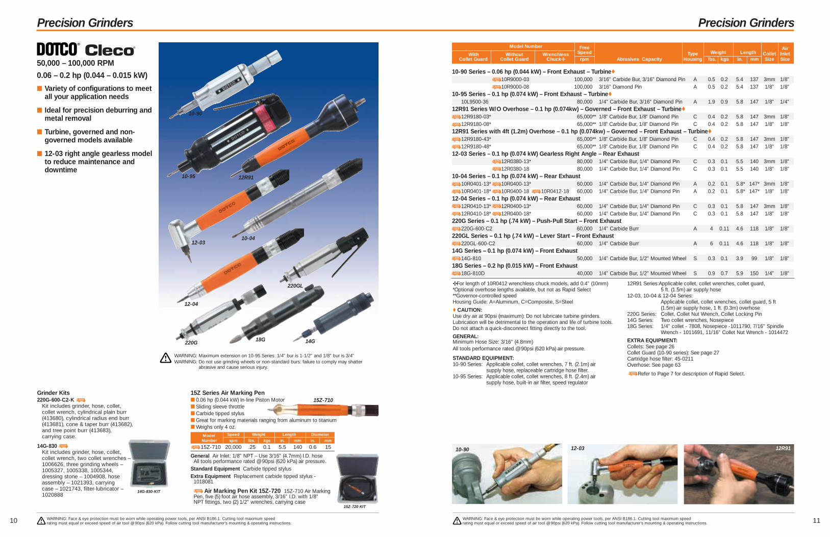
✢For length of 10R0412 wrenchless chuck models, add 0.4” (10mm)*Optional overhose lengths available, but not as Rapid Select**Governor-controlled speedHousing Guide: A=Aluminum, C=Composite, S=Steel
♦ CAUTION:Use dry air at 90psi (maximum): Do not lubricate turbine grinders.Lubrication will be detrimental to the operation and life of turbine tools.Do not attach a quick-disconnect fitting directly to the tool.
GENERAL:Minimum Hose Size: 3/16” (4.8mm)All tools performance rated @ 90psi (620 kPa) air pressure.
STANDARD EQUIPMENT:10-90 Series: Applicable collet, collet wrenches, 7 ft. (2.1m) air
supply hose, replaceable cartridge hose filter.10-95 Series: Applicable collet, collet wrenches, 8 ft. (2.4m) air
supply hose, built-in air filter, speed regulator
12R91 Series:Applicable collet, collet wrenches, collet guard, 5 ft. (1.5m) air supply hose
12-03, 10-04 & 12-04 Series: Applicable collet, collet wrenches, collet guard, 5 ft (1.5m) air supply hose, 1 ft. (0.3m) overhose
220G Series: Collet, Collet Nut Wrench, Collet Locking Pin14G Series: Two collet wrenches, Nosepiece18G Series: 1/4” collet - 7808, Nosepiece -1011790, 7/16” Spindle
Wrench - 1011691, 11/16” Collet Nut Wrench - 1014472
EXTRA EQUIPMENT:Collets: See page 26Collet Guard (10-90 series): See page 27Cartridge hose filter: 45-0211Overhose: See page 63
Refer to Page 7 for description of Rapid Select.
10-90
10-95 12R91
10-90 Series – 0.06 hp (0.044 kW) – Front Exhaust – Turbine♦
10R9000-03 100,000 3/16” Carbide Bur, 3/16” Diamond Pin A 0.5 0.2 5.4 137 3mm 1/8”10R9000-08 100,000 3/16” Diamond Pin A 0.5 0.2 5.4 137 1/8” 1/8”
10-95 Series – 0.1 hp (0.074 kW) – Front Exhaust – Turbine♦
10L9500-36 80,000 1/4” Carbide Bur, 3/16” Diamond Pin A 1.9 0.9 5.8 147 1/8” 1/4”12R91 Series W/O Overhose – 0.1 hp (0.074kw) – Governed – Front Exhaust – Turbine♦
12R9180-03* 65,000** 1/8” Carbide Bur, 1/8” Diamond Pin C 0.4 0.2 5.8 147 3mm 1/8”12R9180-08* 65,000** 1/8” Carbide Bur, 1/8” Diamond Pin C 0.4 0.2 5.8 147 1/8” 1/8”
12R91 Series with 4ft (1.2m) Overhose – 0.1 hp (0.074kw) – Governed – Front Exhaust – Turbine♦
12R9180-43* 65,000** 1/8” Carbide Bur, 1/8” Diamond Pin C 0.4 0.2 5.8 147 3mm 1/8”12R9180-48* 65,000** 1/8” Carbide Bur, 1/8” Diamond Pin C 0.4 0.2 5.8 147 1/8” 1/8”
12-03 Series – 0.1 hp (0.074 kW) Gearless Right Angle – Rear Exhaust12R0380-13* 80,000 1/4” Carbide Bur, 1/4” Diamond Pin C 0.3 0.1 5.5 140 3mm 1/8”12R0380-18 80,000 1/4” Carbide Bur, 1/4” Diamond Pin C 0.3 0.1 5.5 140 1/8” 1/8”
10-04 Series – 0.1 hp (0.074 kW) – Rear Exhaust10R0401-13* 10R0400-13* 60,000 1/4” Carbide Bur, 1/4” Diamond Pin A 0.2 0.1 5.8* 147* 3mm 1/8”10R0401-18* 10R0400-18 10R0412-18 60,000 1/4” Carbide Bur, 1/4” Diamond Pin A 0.2 0.1 5.8* 147* 1/8” 1/8”
12-04 Series – 0.1 hp (0.074 kW) – Rear Exhaust12R0410-13* 12R0400-13* 60,000 1/4” Carbide Bur, 1/4” Diamond Pin C 0.3 0.1 5.8 147 3mm 1/8”12R0410-18* 12R0400-18* 60,000 1/4” Carbide Bur, 1/4” Diamond Pin C 0.3 0.1 5.8 147 1/8” 1/8”
220G Series – 0.1 hp (.74 kW) – Push-Pull Start – Front Exhaust220G-600-C2 60,000 1/4” Carbide Burr A 4 0.11 4.6 118 1/8” 1/8”
220GL Series – 0.1 hp (.74 kW) – Lever Start – Front Exhaust220GL-600-C2 60,000 1/4” Carbide Burr A 6 0.11 4.6 118 1/8” 1/8”
14G Series – 0.1 hp (0.074 kW) – Front Exhaust14G-810 50,000 1/4” Carbide Bur, 1/2” Mounted Wheel S 0.3 0.1 3.9 99 1/8” 1/8”
18G Series – 0.2 hp (0.015 kW) – Front Exhaust18G-810D 40,000 1/4” Carbide Bur, 1/2” Mounted Wheel S 0.9 0.7 5.9 150 1/4” 1/8”
WARNING: Face & eye protection must be worn while operating power tools, per ANSI B186.1. Cutting tool maximum speed rating must equal or exceed speed of air tool @ 90psi (620 kPa). Follow cutting tool manufacturer’s mounting & operating instructions.
Precision Grinders
WARNING: Face & eye protection must be worn while operating power tools, per ANSI B186.1. Cutting tool maximum speed rating must equal or exceed speed of air tool @ 90psi (620 kPa). Follow cutting tool manufacturer’s mounting & operating instructions.
50,000 – 100,000 RPM
0.06 – 0.2 hp (0.044 – 0.015 kW)
■ Variety of configurations to meetall your application needs
■ Ideal for precision deburring andmetal removal
■ Turbine, governed and non-governed models available
■ 12-03 right angle gearless modelto reduce maintenance anddowntime
12-0310-04
12-04
Model Number Free AirWith Without Wrenchless Speed Type Weight Length Collet Inlet
Collet Guard Collet Guard Chuck✢ rpm Abrasives Capacity Housing lbs. kgs in. mm Size Size
220G
220GL
14G
14G-830-KIT
Grinder Kits220G-600-C2-K
Kit includes grinder, hose, collet, collet wrench, cylindrical plain burr (413680), cylindrical radius end burr (413681), cone & taper burr (413682), and tree point burr (413683), carrying case.
14G-830Kit includes grinder, hose, collet, collet wrench, two collet wrenches – 1006626, three grinding wheels – 1005327, 1005338, 1005344, dressing stone – 1004908, hose assembly – 1021393, carrying case – 1021743, filter-lubricator – 1020888
15Z Series Air Marking Pen■ 0.06 hp (0.044 kW) In-line Piston Motor■ Sliding sleeve throttle■ Carbide tipped stylus■ Great for marking materials ranging from aluminum to titanium■ Weighs only 4 oz.
Model Speed Weight Length Diameter
Number spm lbs. kgs in. mm in. mm
15Z-710 20,000 .25 0.1 5.5 140 0.6 15
15Z-710
15Z-720 KIT
General Air Inlet: 1/8” NPT – Use 3/16” (4.7mm) I.D. hoseAll tools performance rated @ 90psi (620 kPa) air pressure.
Standard Equipment Carbide tipped stylusExtra Equipment Replacement carbide tipped stylus -
1018081
Air Marking Pen Kit 15Z-720 15Z-710 Air Marking Pen, five (5) foot air hose assembly, 3/16” I.D. with 1/8” NPT fittings, two (2) 1/2” wrenches, carrying case
10-90 12-03 12R91
18G
WARNING: Maximum extension on 10-95 Series: 1/4” bur is 1-1/2” and 1/8” bur is 3/4”WARNING: Do not use grinding wheels or non-standard burs: failure to comply may shatter
abrasive and cause serious injury.

Inline GrindersFor Carbide Burrs, Mounted Points, Mounted Wheels
13
Inline GrindersFor Carbide Burrs, Mounted Points, Mounted Wheels
12
12,000 – 40,000 RPM
0.2 – 0.9 hp (0.15 – 0.67 kW)
■ Great for die and mold work,deburring
■ Aluminum, composite or ruggedsteel housings
■ Complete selection of rpmspeeds available
■ Front, side, and rear exhaustmodels available
Free AirModel Number Speed Type Weight Length Collet Inlet
Front Exhaust Side Exhaust Rear Exhaust rpm Abrasives Capacity Housing lbs. kgs in. mm Size Size
12-20
Housing Guide: A=Aluminum, C=Composite, S=Steel▲ Button throttle available but not Rapid Select• Oilless blades+ Overhose model available but not necessarily as Rapid Select*Governor controlled speed. If front exhaust, add 0.7” (18mm) to length**For 31G series rear exhaust model, add 0.6” (18mm)‡Mounted wheel capacity depends on wheel diameter, thickness and
overhang. Consult wheel manufacturer for speed recommendations.
GENERAL:All tools performance rated @ 90psi (620 kPa) air pressure.Minimum Hose I.D.–
12-05 Series: 3/16” (4.8mm)10-10, 12-10, 116 Series: 1/4” (6.4mm)
10-20, 10-25, 12-20, 12-25, 136, 31G Series: 5/16” (7.9mm)
STANDARD EQUIPMENT:12-05 Series:
Applicable collet, collet wrenches, collet guard, 7 ft (2.1m) air supply hose
12-10, 12-20, 12-25, 10-10, 10-20, 10-25, 116, 136, 31G Series: Applicable collet, collet wrenches
EXTRA EQUIPMENT:For lock-off safety lever, substitute “S” for “L” in model number.See pages 24–27Overhose (rear exhaust): See page 63
Refer to Page 7 for description of Rapid Select.
12-05
12-10
10-10
10-20
12-20
12-25
WARNING: Face & eye protection must be worn while operating power tools, per ANSI B186.1. Cutting tool maximum speed rating must equal or exceed speed of air tool @ 90psi(620 kPa). Follow cutting tool manufacturer’s mounting & operating instructions. Tools must be equipped with lock-off lever to be CE compliant.
WARNING: Face & eye protection must be worn while operating power tools, per ANSI B186.1. Cutting tool maximum speed rating must equal or exceed speed of air tool @ 90psi(620 kPa). Follow cutting tool manufacturer’s mounting & operating instructions. Tools must be equipped with lock-off lever to be CE compliant.
116GLS
136GLR
12-05
12-05 Series – 0.2 hp (0.15 kW) – with Collet Guard12R0500-36 40,000 1/4” Carbide Burr, 7/8” Mtd. Wheel C 0.7 0.3 5.9 150 1/4” 1/8”
12-10 Series – 0.3 hp (0.22 kW) – 300 Series Collet12L1001-36 12L1081-36+ 34,000 1/2” Carbide Burr, 1” Mtd. Wheel C 0.8 0.4 6.0 152 1/4” 1/4”12L1000-36 12L1080-36▲+ 30,000 1/2” Carbide Burr, 1” Mtd. Wheel C 0.8 0.4 6.0 152 1/4” 1/4”12L1003-36• 12L1082-36•+ 25,000 1/2” Carbide Burr, 1” Mtd. Wheel C 0.8 0.4 6.0 152 1/4” 1/4”12S1008-36• 20,000 1/2” Carbide Burr, 1” Mtd. Wheel C 0.8 0.4 6.0 152 1/4” 1/4”
10-10 Series – 0.3 hp (0.22 kW) – 300 Series Collet10L1001-36▲ 10L1081-36 34,000 1/2” Carbide Burr, 1” Mtd. Wheel A 0.7 0.3 4.6 117 1/4” 1/4”10L1000-36▲ 10L1080-36▲ 30,000 1/2” Carbide Burr, 1” Mtd. Wheel A 0.7 0.3 4.6 117 1/4” 1/4”10L1003-36• 10L1082-36▲• 25,000 1/2” Carbide Burr, 1” Mtd. Wheel A 0.7 0.3 4.6 117 1/4” 1/4”
12-20 Series – 0.6 hp (0.45 kW) – 200 Series Collet12L2000-01 12L2080-01▲+ 25,000 3/4” Carbide Burr, 11/2” Mtd. Wheel C 1.4 0.6 6.9 175 1/4” 1/4”12L2001-01• 12L2081-01• 20,000 3/4” Carbide Burr, 11/2” Mtd. Wheel C 1.4 0.6 6.9 175 1/4” 1/4”12L2002-01• 12L2082-01• 18,000 3/4” Carbide Burr, 11/2” Mtd. Wheel C 1.4 0.6 6.9 175 1/4” 1/4”
10-20 Series – 0.6 hp (0.45 kW) – 200 Series Collet10L2000-01▲ 10L2080-01 25,000 3/4” Carbide Burr, 11/2” Mtd. Wheel A 1.3 0.6 5.8 147 1/4” 1/4”
116 Series – 0.6 hp (0.45 kW) – 200 Series Collet116GLFB-250-C4 25,000 3/4” Carbide Burr S 1.8 0.8 6.3 160 1/4” 1/4”
116GLSB-250-C4 25,000 3/4” Carbide Burr S 1.8 0.8 6.3 160 1/4” 1/4”136 Series – 0.6 hp (0.45 kW) – 200 Series Collet
136GLR-250-C4 25,000 1” Carbide Burr S 1.9 0.9 7.4 188 1/4” 1/4”136GLF-250-C4 25,000 1” Carbide Burr S 2.0 0.9 6.8 173 1/4” 1/4”
136GLS-240-C4 24,000 1” Carbide Burr S 2.0 0.9 6.8 173 1/4” 1/4”136GLR-180-C4 18,000 1” Carbide Burr A 1.9 0.9 7.4 188 1/4” 1/4”
31G Series – 0.6 hp (0.45 kW) – Universal Collet31G-510 31GR-510 20,000* 3/4” Carbide Burr, 11/2” Mtd. Wheel S 1.6 0.7 6.8**173** 1/4” 1/4”
12-25 Series – 0.9 hp (0.67 kW) – 200 Series Collet12L2500-01 12L2580-01+ 23,000 1” Carbide Burr, 11/2” Mtd. Wheel C 1.8 0.8 7.3 185 1/4” 1/4”12L2502-01• 12L2582-01•+ 18,000 1” Carbide Burr, 11/2” Mtd. Wheel C 1.8 0.8 7.3 185 1/4” 1/4”12L2562-01• 12L2542-01• 12,000* 1” Carbide Burr, 11/2” Mtd. Wheel C 1.8 0.8 7.4 188 1/4” 1/4”
10-25 Series – 0.9 hp (0.67 kW) – 200 Series Collet10L2500-01 10L2580-01 23,000 1” Carbide Burr, 11/2” Mtd. Wheel A 1.4 0.6 6.3 159 1/4” 1/4”10B2500-01 23,000 1” Carbide Burr, 11/2” Mtd. Wheel A 1.4 0.6 6.3 159 1/4” 1/4”10L2502-01• 18,000 1” Carbide Burr, 11/2” Mtd. Wheel A 1.4 0.6 6.3 159 1/4” 1/4”
31G
10-25
New! Ergonomic Safety LeverBeginning July 2004, all Dotco“S” tools will be shipped with ournew comfort grip safety lever.

1514
Inline Extended GrindersFor Carbide Burrs, Mounted Points, Mounted Wheels
Inline Extended GrindersFor Carbide Burrs, Mounted Points, Mounted Wheels
12-11 Series - 0.3 hp (0.22 kW) - 5” (127mm) Extension - 300 Series Collet12L1101-36 12L1181-36 28,000 1/2” Carbide Burr, 1” Mtd. Wheel C 1.3 0.6 10.9 277 1/4” 1/4”12L1112-36• 25,000 1/2” Carbide Burr, 1” Mtd. Wheel C 1.3 0.6 10.9 277 1/4” 1/4”
10-11 Series - 0.3 hp (0.22 kW) - 5” (127mm) Extension - 300 Series Collet10L1101-36 10L1181-36 28,000 1/2” Carbide Burr, 1” Mtd. Wheel A 1.2 0.5 9.8 248 1/4” 1/4”10L1112-36▲ 25,000 1/2” Carbide Burr, 1” Mtd. Wheel A 1.2 0.5 9.8 248 1/4” 1/4”
136 Series – 0.8 hp (0.6 kW) – 200 Series Collet136GEL-240-C4 24,000 1” Carbide Burr, 2” Mtd. Wheel S 3.5 1.6 12.4 315 1/4” 1/4”
12-26 Series - 0.9 hp (0.67 kW) - 5” (127mm) Extension - 200 Series Collet12L2600-01 22,000 1” Carbide Burr, 11/2” Mtd. Wheel C 2.9 1.3 12.9 328 1/4” 1/4”
12L2682-01• 18,000 1” Carbide Burr, 11/2” Mtd. Wheel C 2.9 1.3 12.9 328 1/4” 1/4”12-26 Series – 0.9 hp (0.67 kW) – Multiple Extension - 300 Series Collet
12S2674-2A• 18,000 3/4” Carbide Burr, 11/2” Mtd. Wheel C 4.2 1.9 23.5 597 1/4” 1/4”15 Series – 1.2 hp (0.9 kW) – 200 Series Collet – Governed
15GELC-180-C4 18,000* 11/4” Carbide Burr, 2” Mtd. Wheel S 4.3 2.0 14.5 368 1/4” 3/8”
18,000 – 28,000 RPM
0.3 – 1.2 hp (0.22 – 0.9 kW)
■ Extended housings
■ Aluminum, composite or ruggedsteel housings
Free AirModel Number Speed Type Weight Length Collet Inlet
Front Exhaust Side Exhaust Rear Exhaust rpm Abrasives Capacity Housing lbs. kgs in. mm Size Size
12-11
Housing Guide: A=Aluminum, C=Composite, S=Steel▲ Button throttle available but not Rapid Select*Governor controlled speeds• Oilless blades‡Mounted wheel capacity depends on wheel diameter, thickness and
overhang. Consult wheel manufacturer for speed recommendations.
GENERAL:All tools performance rated @ 90psi (620 kPa) air pressure.Minimum Hose I.D.–
10-11, 12-11 Series: 1/4” (4.8mm)12-26, 136 Series: 5/16” (7.9mm)15 (governed) Series: 3/8” (9.5mm)
STANDARD EQUIPMENT:Applicable collet, collet wrenches
EXTRA EQUIPMENT:See pages 24–27Overhose (rear exhaust): See page 63
MULTIPLE EXTENSIONS FOR 12-26 SERIES:Each extension changes the tool length and weight by:12-26 series = 7.25” (184mm) and 1.2 lbs. (0.54 kg);The length and weight in the table are for 2A models
1A = One extension2A = Two extension3A = Three extensions, etc.
All multiple extensions are not available in all speeds
Refer to Page 7 for description of Rapid Select.
12-11
12-26
12-26
WARNING: Face & eye protection must be worn while operating power tools, per ANSI B186.1. Cutting tool maximum speed rating must equal or exceed speed of air tool @ 90psi(620 kPa). Follow cutting tool manufacturer’s mounting & operating instructions. Tools must be equipped with lock-off lever to be CE compliant.
WARNING: Face & eye protection must be worn while operating power tools, per ANSI B186.1. Cutting tool maximum speed rating must equal or exceed speed of air tool @ 90psi(620 kPa). Follow cutting tool manufacturer’s mounting & operating instructions. Tools must be equipped with lock-off lever to be CE compliant.
136G
15G
10-11
New! Ergonomic Safety LeverBeginning July 2004, all Dotco“S” tools will be shipped with ournew comfort grip safety lever.

1716
Right Angle GrindersFor Carbide Burrs, Mounted Points, Mounted Wheels
Right Angle GrindersFor Carbide Burrs, Mounted Points, Mounted Wheels
6,000 – 30,000 RPM
0.3 – 0.9 hp (0.22 – 0.67 kW)
■ Suitable for a wide range offinishing and deburringapplications
■ Geared or gearless
■ Front, side, or rear exhaust
■ Heavy duty heads available formore rugged applications
■ Extended head models available
12-12
12-13
12-23
12-27
12-22 12-27Heavy Duty
Head
12-12 12-22
WARNING: Face & eye protection must be worn while operating power tools, per ANSI B186.1. Cutting tool maximum speed rating must equal or exceed speed of air tool @ 90psi(620 kPa). Follow cutting tool manufacturer’s mounting & operating instructions. Tools must be equipped with lock-off lever to be CE compliant.
WARNING: Face & eye protection must be worn while operating power tools, per ANSI B186.1. Cutting tool maximum speed rating must equal or exceed speed of air tool @ 90psi(620 kPa). Follow cutting tool manufacturer’s mounting & operating instructions. Tools must be equipped with lock-off lever to be CE compliant.
12-12 & 10-12 Series – 0.3 hp (0.22 kW) – 300 Series Collet12L1201-36 12L1281-36 20,000 1/2” Carbide Burr, 1” Mtd. Whl. C 1.1 0.5 2.7 69 6.3 160 1/4” 1/4”12L1200-36 12L1280-36 12,000 1/2” Carbide Burr, 1” Mtd. Whl. C 1.1 0.5 2.7 69 6.3 160 1/4” 1/4”10L1201-36 10L1281-36 20,000 1/2” Carbide Burr, 1” Mtd. Whl. C 1.0 0.5 2.9 74 5.0 127 1/4” 1/4”10L1200-36 10L1280-36 12,000 1/2” Carbide Burr, 1” Mtd. Whl. C 1.0 0.5 2.9 74 5.0 127 1/4” 1/4”
12-13 Series – 0.3 hp (0.22 kW) – Gearless – 300 Series Collet12L1380-36 30,000 1/2” Carbide Burr, 1” Mtd. Whl. C 1.1 0.5 3.7 94 7.1 180 1/4” 1/4”12L1381-36 25,000 1/2” Carbide Burr, 1” Mtd. Whl. C 1.1 0.5 3.7 94 7.1 180 1/4” 1/4”12L1382-36• 20,000 1/2” Carbide Burr, 1” Mtd. Whl. C 1.1 0.5 3.7 94 7.1 180 1/4” 1/4”
12-23 Series – 0.5 hp (0.38 kW) – Gearless – 200 Series Collet12L2384-01 20,000 3/4” Carbide Burr, 11/4” Mtd. Whl. C 2.0 0.91 5.5 140 7.5 190 1/4” 1/4”
12-22 Series – 0.6 hp (0.45 kW) – 200 Series Collet – Heavy Duty Head12L2252-01• 11,000 3/4” Carbide Burr, 2” Mtd. Whl. C 3.2 1.5 3.9 99 9.3 236 1/4” 1/4”
12-22 Series – 0.6 hp (0.45 kW) – 300 Series Collet12L2218-36 18,000 1/2” Carbide Burr, 1” Mtd. Whl. C 1.7 0.8 2.7 69 7.5 191 1/4” 1/4”
116 Series – 0.6 hp (0.4 kW) – 200 Series Collet – Heavy Duty Head116GLF-115A-C4 11,500 1” Carbide Burr S 3.3 1.5 7.1 180 1/4” 1/4”
116 Series – 0.6 hp (0.4 kW) – 200 Series Collet – Extended Head116GLFC-165A-C4 16,500 3/4” Carbide Burr S 2.6 1.2 9.1 231 1/4” 1/4”
136 Series – 0.8 hp (0.6 kW) – 200 Series Collet – Heavy Duty Head136GLR-115A-C4 11,500 1” Carbide Burr S 3.4 1.5 8.3 211 1/4” 1/4”
12-27 Series – 0.9 hp (0.67 kW) – 200 Series Collet – Heavy Duty Head12L2752-01 11,000 1” Carbide Burr, 2” Mtd. Whl. C 3.4 1.5 3.9 99 9.8 249 1/4” 1/4”
12-27 Series – 0.9 hp (0.67 kW) – 300 Series Collet12L2718-36 18,000 3/4” Carbide Burr, 11/4” Mtd. Whl. C 1.9 0.9 2.9 74 8.0 203 1/4” 1/4”
Free Head AirModel Number Speed Type Weight Height* Length Collet Inlet
Front Exhaust Side Exhaust Rear Exhaust rpm Abrasives Capacity‡ Housing lbs. kgs in. mm in. mm Size Size
Housing Guide: A=Aluminum, C=Composite, S=Steel* Over spindle• Oilless blades‡Mounted wheel capacity depends on wheel diameter, thickness and
overhang. Consult wheel manufacturer for speed recommendations.GENERAL:All tools performance rated @ 90psi (620 kPa) air pressure.Minimum Hose I.D.– 12-12, 10-12, 12-13, 12-23, 116 Series: 1/4” (4.8mm)
12-22, 12-27, 136 Series: 5/16” (7.9mm)
STANDARD EQUIPMENT:Applicable collet, collet wrenchesEXTRA EQUIPMENT:For lock-off safety lever, substitute “S” for “L” in model number.See pages 24–27Overhose (rear exhaust): See page 63
Refer to Page 7 for description of Rapid Select.
12-22Heavy Duty
Head
New! Ergonomic Safety LeverBeginning July 2004, all Dotco“S” tools will be shipped with ournew comfort grip safety lever.
136GLRHeavy Duty
Head
116GLExtended
Head

136GLR
560BHL
1760HL
1960HG
1918
Inline GrindersFor Cone or Plug Wheels
Inline GrindersFor Type 1 Wheels
136 Series Extended – 0.8 hp (0.6 kW) – Non-Governed – Side Exhaust136GEL-240-P3T 24,000 1 1/4" Cone or Plug Wheel S 3.5 1.6 12.3 312 3/8"-24 1/4”
15 Extended Series – 1.2 hp (0.9 kW) – Governed – Rotatable Exhaust Deflector15GELC-180-P3T 18,000* 2” Cone or Plug Wheel S 4.3 2.0 14.5 368 3/8”-24 1/4”15GELC-180-P5T 18,000* 2” Cone or Plug Wheel S 4.5 2.0 14.9 378 5/8”-11 1/4”15GELC-140-P3T 14,000* 2” Cone or Plug Wheel S 4.3 2.0 14.5 368 3/8”-24 1/4”
500B Horizontal Series – 2.1 hp (1.6 kW) – Governed – Rotatable Exhaust Deflector590BHL-P 9,000* 3” Cone or Plug Wheel S 7.6 3.4 17.9 455 5/8”-11 1/4”5120BHL-P 12,000* 3” Cone or Plug Wheel S 7.6 3.4 17.9 455 5/8”-11 1/4”
9,000 – 24,000 RPM
0.8 – 2.1 hp (0.6 – 1.6 kW)
■ Governed and non-governedmodels
■ Side exhaust
■ Extended Series
■ Rugged steel housings
Housing Guide: A=Aluminum, C=Composite, S=Steel*Governor controlled speedsGENERAL:All tools performance rated @ 90psi (620 kPa) air pressure.Minimum Hose I.D.– 136, 15, 500B Series: 5/16” (7.9mm)
STANDARD EQUIPMENT:Applicable wrenches, operating instructions & service manualEXTRA EQUIPMENT:See pages 28–31Overhose (rear exhaust): See page 63
Refer to Page 7 for description of Rapid Select.
WARNING: Face & eye protection must be worn while operating power tools, per ANSI B186.1. Cutting tool maximum speed rating must equal or exceed speed of air tool @ 90psi(620 kPa). Follow cutting tool manufacturer’s mounting & operating instructions. Tools must be equipped with lock-off lever to be CE compliant.
WARNING: Face & eye protection must be worn while operating power tools, per ANSI B186.1. Cutting tool maximum speed rating must equal or exceed speed of air tool @ 90psi(620 kPa). Follow cutting tool manufacturer’s mounting & operating instructions. Tools must be equipped with lock-off lever to be CE compliant.
15GELC
590BHL
Free AirModel Number Speed Type Weight Length Spindle Inlet
Rear Exhaust Rotatable Side Exhaust rpm Abrasives Capacity Housing lbs. kgs in. mm Size Size
136GEL
136 Series – 0.5 hp (0.4 kW) – Rear Exhaust136GLR-180-W3T4 18,000 3” x 1/2” (4”wheel guard) S 2.4 1.1 7.3 185 3/8”-24 1/4”136GLR-150-W3T4 15,000 3” x 1/2” (4”wheel guard) S 2.4 1.1 7.3 185 3/8”-24 1/4”
500B Series – 1.9 hp (1.4kW) – Rotatable Exhaust 560BHL-16 6,000 6” x 1” (6”wheel guard) S 10.8 4.9 18.4 467 5/8” 1/2”
500B Series – 1.9 hp (1.4kW) – Rotatable Exhaust – Spade Handle560BHX-16 6,000 6” x 1” (6”wheel guard) S 11.6 5.3 18.8 478 5/8” 1/2”
1700 Series – 3.1 hp (2.3kW) – Lock-off Lever Throttle1760HL-16 6,000* 6” x 1” (6”wheel guard) S 14.5 6.6 19.6 498 5/8” 1/2”
1900 Series – 4.1 hp (3.1 kW) – Spade Handle1960HG-16 6,000* 6” x 1” (6”wheel guard) S 6.8 7.6 21.4 544 5/8” 1/2”
Housing Guide: A=Aluminum, C=Composite, S=Steel* Governor controlled speeds
GENERAL:All tools performance rated @ 90psi (620 kPa) air pressure.Minimum Hose I.D.– 560, 1700, 1900 Series: 1/2” (12.7mm)
STANDARD EQUIPMENT:136, 500B, 1700 & 1900 series: Wheel guard and flange wrench
EXTRA EQUIPMENT:See pages 24–27Wheel Guards: See page 27Overhose (rear exhaust): See page 63
Refer to Page 7 for description of Rapid Select.
Free Arbor/ AirModel Number Speed Type Weight Length Spindle Inlet
Rear Exhaust Rotatable Side Exhaust rpm Type 1 Capacity Housing lbs. kgs in. mm Size Size
6,000 – 18,000 RPM
0.5 – 4.1 hp (0.4 – 3.1 kW)
■ Short & extended
■ Side & rear exhaust
■ Safety lever or spade handle
560BHX
2120
Inline & Right Angle GrindersFor Type 1 Cut-Off Wheels
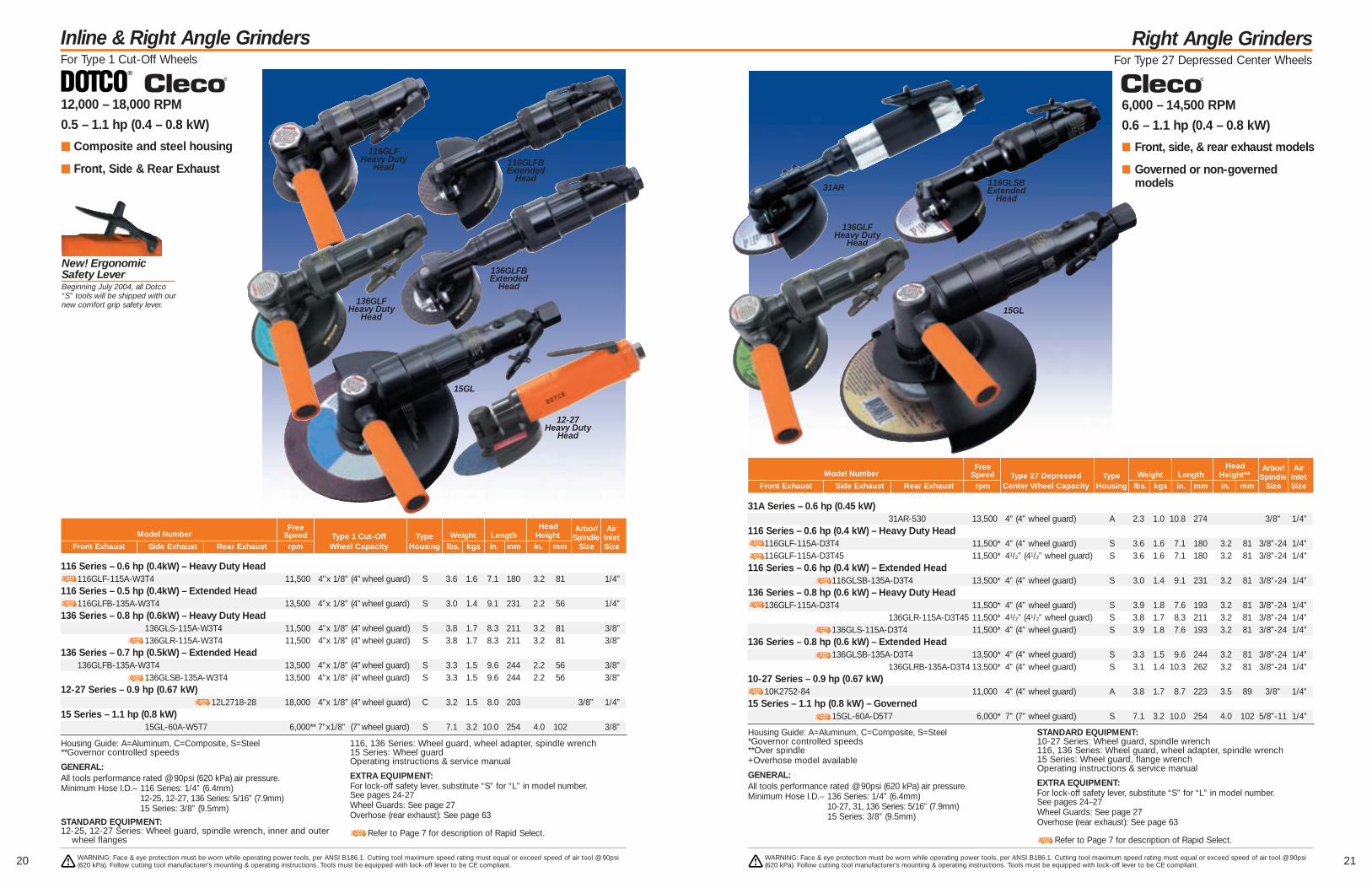
116 Series – 0.6 hp (0.4kW) – Heavy Duty Head116GLF-115A-W3T4 11,500 4”x 1/8” (4”wheel guard) S 3.6 1.6 7.1 180 3.2 81 1/4”
116 Series – 0.5 hp (0.4kW) – Extended Head116GLFB-135A-W3T4 13,500 4”x 1/8” (4”wheel guard) S 3.0 1.4 9.1 231 2.2 56 1/4”
136 Series – 0.8 hp (0.6kW) – Heavy Duty Head136GLS-115A-W3T4 11,500 4”x 1/8” (4”wheel guard) S 3.8 1.7 8.3 211 3.2 81 3/8”136GLR-115A-W3T4 11,500 4”x 1/8” (4”wheel guard) S 3.8 1.7 8.3 211 3.2 81 3/8”
136 Series – 0.7 hp (0.5kW) – Extended Head136GLFB-135A-W3T4 13,500 4”x 1/8” (4”wheel guard) S 3.3 1.5 9.6 244 2.2 56 3/8”
136GLSB-135A-W3T4 13,500 4”x 1/8” (4”wheel guard) S 3.3 1.5 9.6 244 2.2 56 3/8”12-27 Series – 0.9 hp (0.67 kW)
12L2718-28 18,000 4”x 1/8” (4”wheel guard) C 3.2 1.5 8.0 203 3/8” 1/4”15 Series – 1.1 hp (0.8 kW)
15GL-60A-W5T7 6,000** 7”x1/8” (7”wheel guard) S 7.1 3.2 10.0 254 4.0 102 3/8”
12,000 – 18,000 RPM
0.5 – 1.1 hp (0.4 – 0.8 kW)
m Composite and steel housing
m Front, Side & Rear Exhaust
WARNING: Face & eye protection must be worn while operating power tools, per ANSI B186.1. Cutting tool maximum speed rating must equal or exceed speed of air tool @ 90psi(620 kPa). Follow cutting tool manufacturer’s mounting & operating instructions. Tools must be equipped with lock-off lever to be CE compliant.
WARNING: Face & eye protection must be worn while operating power tools, per ANSI B186.1. Cutting tool maximum speed rating must equal or exceed speed of air tool @ 90psi(620 kPa). Follow cutting tool manufacturer’s mounting & operating instructions. Tools must be equipped with lock-off lever to be CE compliant.
15GL
Free Head Arbor/ AirModel Number Speed Type 1 Cut-Off Type Weight Length Height Spindle Inlet
Front Exhaust Side Exhaust Rear Exhaust rpm Wheel Capacity Housing lbs. kgs in. mm in. mm Size Size
Housing Guide: A=Aluminum, C=Composite, S=Steel**Governor controlled speeds
GENERAL:All tools performance rated @ 90psi (620 kPa) air pressure.Minimum Hose I.D.– 116 Series: 1/4” (6.4mm)
12-25, 12-27, 136 Series: 5/16” (7.9mm)15 Series: 3/8” (9.5mm)
STANDARD EQUIPMENT:12-25, 12-27 Series: Wheel guard, spindle wrench, inner and outer
wheel flanges
116, 136 Series: Wheel guard, wheel adapter, spindle wrench15 Series: Wheel guardOperating instructions & service manual
EXTRA EQUIPMENT:For lock-off safety lever, substitute “S” for “L” in model number.See pages 24-27Wheel Guards: See page 27Overhose (rear exhaust): See page 63
Refer to Page 7 for description of Rapid Select.
116GLFBExtended
Head
116GLFHeavy Duty
Head
136GLFBExtended
Head
New! Ergonomic Safety LeverBeginning July 2004, all Dotco“S” tools will be shipped with ournew comfort grip safety lever.
Right Angle GrindersFor Type 27 Depressed Center Wheels
6,000 – 14,500 RPM
0.6 – 1.1 hp (0.4 – 0.8 kW)
■ Front, side, & rear exhaust models
■ Governed or non-governedmodels
31A Series – 0.6 hp (0.45 kW)31AR-530 13,500 4” (4” wheel guard) A 2.3 1.0 10.8 274 3/8" 1/4”
116 Series – 0.6 hp (0.4 kW) – Heavy Duty Head116GLF-115A-D3T4 11,500* 4” (4” wheel guard) S 3.6 1.6 7.1 180 3.2 81 3/8”-24 1/4”116GLF-115A-D3T45 11,500* 41/2” (41/2” wheel guard) S 3.6 1.6 7.1 180 3.2 81 3/8”-24 1/4”
116 Series – 0.6 hp (0.4 kW) – Extended Head116GLSB-135A-D3T4 13,500* 4” (4” wheel guard) S 3.0 1.4 9.1 231 3.2 81 3/8”-24 1/4”
136 Series – 0.8 hp (0.6 kW) – Heavy Duty Head136GLF-115A-D3T4 11,500* 4” (4” wheel guard) S 3.9 1.8 7.6 193 3.2 81 3/8”-24 1/4”
136GLR-115A-D3T45 11,500* 41/2” (41/2” wheel guard) S 3.8 1.7 8.3 211 3.2 81 3/8”-24 1/4”136GLS-115A-D3T4 11,500* 4” (4” wheel guard) S 3.9 1.8 7.6 193 3.2 81 3/8”-24 1/4”
136 Series – 0.8 hp (0.6 kW) – Extended Head136GLSB-135A-D3T4 13,500* 4” (4” wheel guard) S 3.3 1.5 9.6 244 3.2 81 3/8”-24 1/4”
136GLRB-135A-D3T4 13,500* 4” (4” wheel guard) S 3.1 1.4 10.3 262 3.2 81 3/8”-24 1/4”10-27 Series – 0.9 hp (0.67 kW)
10K2752-84 11,000 4” (4” wheel guard) A 3.8 1.7 8.7 223 3.5 89 3/8” 1/4”15 Series – 1.1 hp (0.8 kW) – Governed
15GL-60A-D5T7 6,000* 7” (7” wheel guard) S 7.1 3.2 10.0 254 4.0 102 5/8”-11 1/4”
Free Head Arbor/ AirModel Number Speed Type 27 Depressed Type Weight Length Height** Spindle Inlet
Front Exhaust Side Exhaust Rear Exhaust rpm Center Wheel Capacity Housing lbs. kgs in. mm in. mm Size Size
Housing Guide: A=Aluminum, C=Composite, S=Steel*Governor controlled speeds**Over spindle+Overhose model available
GENERAL:All tools performance rated @ 90psi (620 kPa) air pressure.Minimum Hose I.D.– 136 Series: 1/4” (6.4mm)
10-27, 31, 136 Series: 5/16” (7.9mm)15 Series: 3/8” (9.5mm)
STANDARD EQUIPMENT:10-27 Series: Wheel guard, spindle wrench116, 136 Series: Wheel guard, wheel adapter, spindle wrench15 Series: Wheel guard, flange wrenchOperating instructions & service manual
EXTRA EQUIPMENT:For lock-off safety lever, substitute “S” for “L” in model number.See pages 24–27Wheel Guards: See page 27Overhose (rear exhaust): See page 63
Refer to Page 7 for description of Rapid Select.
31AR 116GLSBExtended
Head
136GLFHeavy Duty
Head
15GL136GLF
Heavy DutyHead
12-27Heavy Duty
Head
2322 WARNING: Face & eye protection must be worn while operating power tools, per ANSI B186.1. Cutting tool maximum speed rating must equal or exceed speed of air tool @ 90psi(620 kPa). Follow cutting tool manufacturer’s mounting & operating instructions. Tools must be equipped with lock-off lever to be CE compliant.
WARNING: Face & eye protection must be worn while operating power tools, per ANSI B186.1. Cutting tool maximum speed rating must equal or exceed speed of air tool @ 90psi(620 kPa). Follow cutting tool manufacturer’s mounting & operating instructions. Tools must be equipped with lock-off lever to be CE compliant.
Vertical GrindersFor Type 27 Depressed Center Wheel & Cup Wheel
Vertical GrindersFor Type 27 Depressed Center Wheel & Cup Wheel
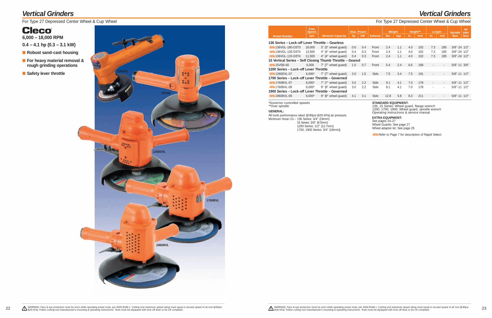
6,000 – 18,000 RPM
0.4 – 4.1 hp (0.3 – 3.1 kW)
■ Robust sand-cast housing
■ For heavy material removal &rough grinding operations
■ Safety lever throttle
136 Series – Lock-off Lever Throttle – Gearless136VGL-180-D3T3 18,000 3” (3” wheel guard) 0.6 0.4 Front 2.4 1.1 4.0 102 7.3 185 3/8”-24 1/2”136VGL-135-D3T4 13,500 4” (4” wheel guard) 0.4 0.3 Front 2.4 1.1 4.0 102 7.3 185 3/8”-24 1/2”136VGL-115-D3T4 11,500 4” (4” wheel guard) 0.4 0.3 Front 2.4 1.1 4.0 102 7.3 185 3/8”-24 1/2”
15 Vertical Series – Self Closing Thumb Throttle – Geared15VSB-60 6,000 7” (7” wheel guard) 1.0 0.7 Front 5.4 2.4 6.6 168 - - 5/8”-11 3/8”
1200 Series – Lock-off Lever Throttle1260DVL-07 6,000* 7” (7” wheel guard) 2.0 1.5 Side 7.5 3.4 7.5 191 - - 5/8”-11 1/2”
1700 Series – Lock-off Lever Throttle – Governed1760BVL-07 6,000* 7” (7” wheel guard) 3.0 2.2 Side 9.1 4.1 7.0 178 - - 5/8”-11 1/2”1760BVL-09 6,000* 9” (9” wheel guard) 3.0 2.2 Side 9.1 4.1 7.0 178 - - 5/8”-11 1/2”
1900 Series – Lock-off Lever Throttle – Governed1960BVL-09 6,000* 9” (9” wheel guard) 4.1 3.1 Side 12.8 5.8 8.3 211 - - 5/8”-11 1/2”
136VGL
15VSB
1260DVL
1760BVL
1960BVL
Free AirSpeed Max. Power Weight Height** Length Spindle Inlet
Model Number rpm Abrasive Capacity hp kW Exhaust lbs. kgs in. mm in. mm Size Size
*Governor controlled speeds**Over spindle
GENERAL:All tools performance rated @ 90psi (620 kPa) air pressure.Minimum Hose I.D.– 136 Series: 3/4” (19mm)
15 Series: 3/8” (9.5mm)1200 Series: 1/2” (12.7mm)1700, 1900 Series: 3/4” (19mm))
STANDARD EQUIPMENT:136, 15 Series: Wheel guard, flange wrench1200, 1700, 1900: Wheel guard, spindle wrenchOperating instructions & service manual
EXTRA EQUIPMENT:See pages 24–27Wheel Guards: See page 27Wheel adapter kit: See page 25
Refer to Page 7 for description of Rapid Select.

Grinder Accessories
25
Grinder Accessories
24
Precision Carbide Burs for Die Grinders
Size Code No. Max. Speed1/4” Shank
Cylindrical Radius End1/16” x 3/4” 889035 80,0003/8” x 3/4” 889036 66,0001/2” x 1” 889038 50,0005/8” x 1” 889039 40,000
Cylindrical Plain3/16” x 5/8” 889003 133,0005/16” x 3/4” 889005 80,0003/8” x 3/4” 889006 66,0005/8” x 1” 889009 40,000
Oval1/4” x 3/8” 889056 100,0003/8” x 5/8” 889057 66,000
Cone Round End 14°1/4” x 5/8” 889135 100,000
5/16” x 7/8” 889101 66,0003/8” x 1 1/16” 889102 50,0001/2” x 1 1/8” 889103 40,0003/4” x 1 1/2” 889106 33,000
Cone or Taper1/4” x 3/4” 889108 100,0003/8” x 5/8” 889132 66,000
Ball1/4” 889046 100,0003/8” 889048 66,0003/8” 889051 40,000
Tree Pointed1/4” x 3/4” 889128 100,000
Tree Radius End1/4” x 3/4” 889128 100,0001/2” x 1” 889067 50,0003/4” x 1” 889069 33,0003/4” x 1 1/2” 889071 33,000
Tool Series Size Part No. Speed (rpm)
Type 1 Wheel116RA, 136RA 3” 202226 13,500 & 16,500116RA, 136RA 4” 889208 11,500116RA, 136RA 4” 202227 13,500 & 16,500136, 15 3” 202278136, 15 4” 20224515RA 7” 20413115H 3” 86578615H 4” 865988500BH 4” 881608 9,000 & 12,000500BH 6” 865993 6,0001700V, 1900V 6” 2020221700V, 1900V 8” 202025
Type 27 Wheel15RA 7” 865986136V 3” 849905136V 4” 203382116RA, 136RA 4” 889208 11,500116RA, 136RA 4 1/2” 202063 11,500116RA, 136RA 3” 202226 13,500 & 16,500116RA, 136RA 4” 202227 13,500 & 16,500116RA, 136RA 5” 203142 11,50015V 7” 8497601200V 7” 2023741200V 9” 2026081700V, 1900V 9” 8677411700V, 1900V 7” 867740
Type 28 Wheel15V 7” 8497601200V 7” 2023741700V, 1900V 7” 86774015RA 7” 8659861700V, 1900V 9” 869067
Type 6 & 11 (Cup) Wheel1200V 4” 2024651700V, 1900V 5” 8618921700V, 1900V 6” 861893
Cleco Wheel Guards
Part No. Size Used On
861792 5” 116RA, 136RA861655 7” 15RA, 15V, 1200V, 1700V, 1900V861656* 9” 1700V, 1900V
* For use on 4,500 and 6,000 rpm models only
Spiral Cool Sanding Kits
Part No. Used On
849269 15V, 1200V, 1700V, 1900V* For 7/8” plain whole wheels
Type 27 & 28 Wheel Adapter Kit*
Part No. Description
869580 Exhaust Overhose869204 Overhose Adapter202343 Hose Clamp
* Rear exhaust models only
Overhose for 136* Grinders
Part No. Used On
861983 116RA, 136RA
4 1/2” Wheel Guard Kit
Part No. Used On
861804 116, 136
Router Attachment
869580
202343
861804
861654 861655
869204
849269
Type 1 (Cut-Off) Wheel31A 4” 1025947
Type 27 Depressed Center Wheel31A 4” 102231231A 4” Thin 102474531A 4 1/2” 1024788
Buckeye Wheel GuardsTool Series Series Guard Number
Part No. Description
1018422 Overhose (5’)
Use with any Buckeye 31 series straight housing toolSecures over the exhaust bushing at the rear of the tool to carry exhaust debris away from the work area.
Exhaust Hose
WARNING: Face & eye protection must be worn while operating power tools, per ANSI B186.1. Cutting tool maximum speed rating must equal or exceed speed of air tool @ 90psi(620 kPa). Follow cutting tool manufacturer’s mounting & operating instructions. Tools must be equipped with lock-off lever to be CE compliant.
WARNING: Face & eye protection must be worn while operating power tools, per ANSI B186.1. Cutting tool maximum speed rating must equal or exceed speed of air tool @ 90psi(620 kPa). Follow cutting tool manufacturer’s mounting & operating instructions. Tools must be equipped with lock-off lever to be CE compliant.
Grinder Accessories
27
Grinder Accessories
26
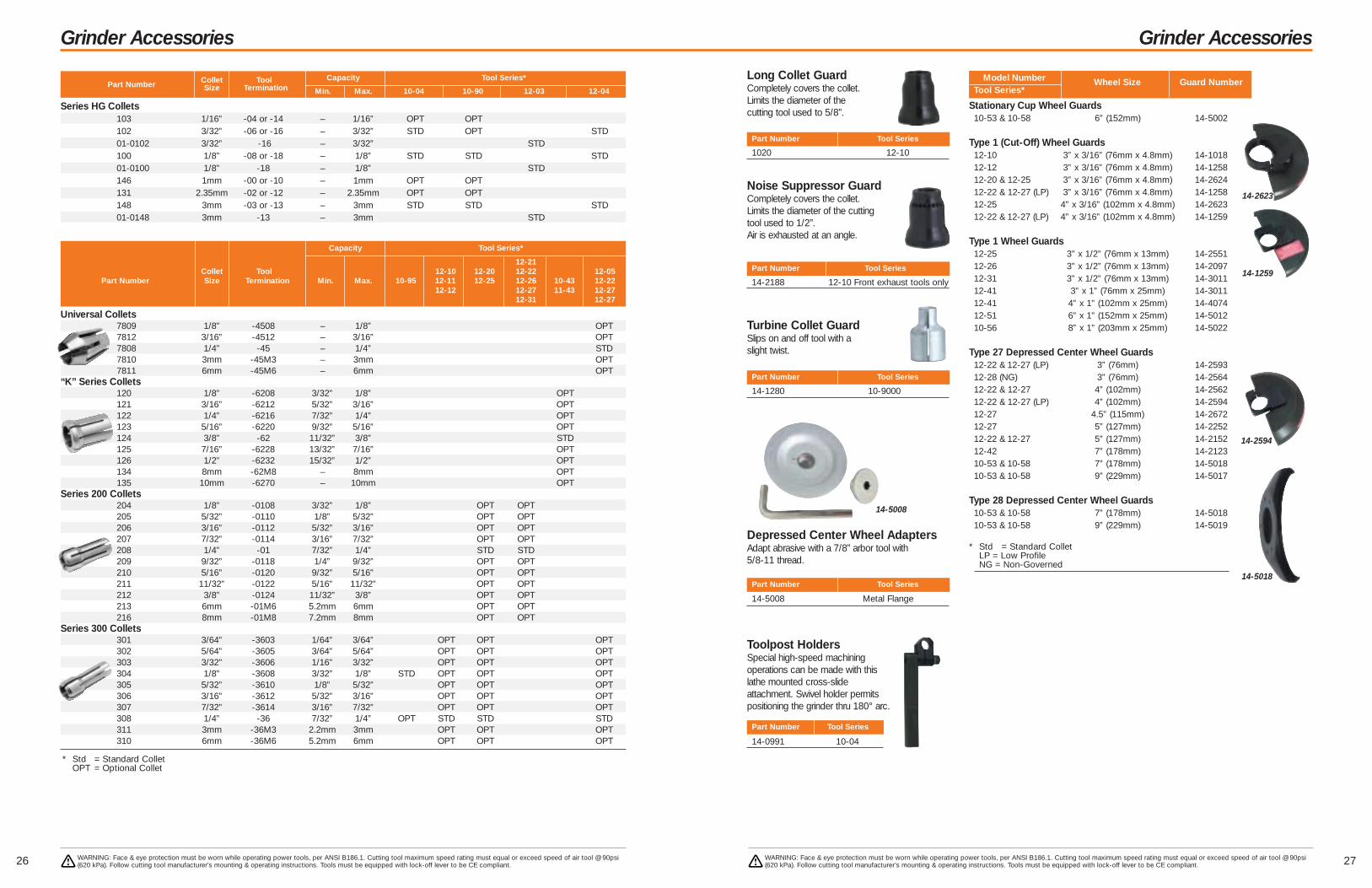
Series HG Collets103 1/16” -04 or -14 – 1/16” OPT OPT102 3/32” -06 or -16 – 3/32” STD OPT STD01-0102 3/32” -16 – 3/32” STD100 1/8” -08 or -18 – 1/8” STD STD STD01-0100 1/8” -18 – 1/8” STD146 1mm -00 or -10 – 1mm OPT OPT131 2.35mm -02 or -12 – 2.35mm OPT OPT148 3mm -03 or -13 – 3mm STD STD STD01-0148 3mm -13 – 3mm STD
Collet Tool Capacity Tool Series*Part Number Size Termination Min. Max. 10-04 10-90 12-03 12-04
Capacity Tool Series*
12-21Collet Tool 12-10 12-20 12-22 12-05
Part Number Size Termination Min. Max. 10-95 12-11 12-25 12-26 10-43 12-2212-12 12-27 11-43 12-27
12-31 12-27
* Std = Standard ColletOPT = Optional Collet
Universal Collets7809 1/8” -4508 – 1/8” OPT7812 3/16” -4512 – 3/16” OPT7808 1/4” -45 – 1/4” STD7810 3mm -45M3 – 3mm OPT7811 6mm -45M6 – 6mm OPT
“K” Series Collets120 1/8” -6208 3/32” 1/8” OPT121 3/16” -6212 5/32” 3/16” OPT122 1/4” -6216 7/32” 1/4” OPT123 5/16” -6220 9/32” 5/16” OPT124 3/8” -62 11/32” 3/8” STD125 7/16” -6228 13/32” 7/16” OPT126 1/2” -6232 15/32” 1/2” OPT134 8mm -62M8 – 8mm OPT135 10mm -6270 – 10mm OPT
Series 200 Collets204 1/8” -0108 3/32” 1/8” OPT OPT205 5/32” -0110 1/8” 5/32” OPT OPT206 3/16” -0112 5/32” 3/16” OPT OPT207 7/32” -0114 3/16” 7/32” OPT OPT208 1/4” -01 7/32” 1/4” STD STD209 9/32” -0118 1/4” 9/32” OPT OPT210 5/16” -0120 9/32” 5/16” OPT OPT211 11/32” -0122 5/16” 11/32” OPT OPT212 3/8” -0124 11/32” 3/8” OPT OPT213 6mm -01M6 5.2mm 6mm OPT OPT216 8mm -01M8 7.2mm 8mm OPT OPT
Series 300 Collets301 3/64” -3603 1/64” 3/64” OPT OPT OPT302 5/64” -3605 3/64” 5/64” OPT OPT OPT303 3/32” -3606 1/16” 3/32” OPT OPT OPT304 1/8” -3608 3/32” 1/8” STD OPT OPT OPT305 5/32” -3610 1/8” 5/32” OPT OPT OPT306 3/16” -3612 5/32” 3/16” OPT OPT OPT307 7/32” -3614 3/16” 7/32” OPT OPT OPT308 1/4” -36 7/32” 1/4” OPT STD STD STD311 3mm -36M3 2.2mm 3mm OPT OPT OPT310 6mm -36M6 5.2mm 6mm OPT OPT OPT
WARNING: Face & eye protection must be worn while operating power tools, per ANSI B186.1. Cutting tool maximum speed rating must equal or exceed speed of air tool @ 90psi(620 kPa). Follow cutting tool manufacturer’s mounting & operating instructions. Tools must be equipped with lock-off lever to be CE compliant.
WARNING: Face & eye protection must be worn while operating power tools, per ANSI B186.1. Cutting tool maximum speed rating must equal or exceed speed of air tool @ 90psi(620 kPa). Follow cutting tool manufacturer’s mounting & operating instructions. Tools must be equipped with lock-off lever to be CE compliant.
Model Number Wheel Size Guard NumberTool Series*
Part Number Tool Series
1020 12-10
Long Collet GuardCompletely covers the collet. Limits the diameter of the cutting tool used to 5/8”.
Depressed Center Wheel AdaptersAdapt abrasive with a 7/8” arbor tool with 5/8-11 thread.
Noise Suppressor GuardCompletely covers the collet.Limits the diameter of the cuttingtool used to 1/2”. Air is exhausted at an angle.
Toolpost HoldersSpecial high-speed machiningoperations can be made with thislathe mounted cross-slideattachment. Swivel holder permitspositioning the grinder thru 180° arc.
Part Number Tool Series
14-5008 Metal Flange
Turbine Collet GuardSlips on and off tool with aslight twist.
Part Number Tool Series
14-2188 12-10 Front exhaust tools only
Part Number Tool Series
14-1280 10-9000
Part Number Tool Series
14-0991 10-04
Stationary Cup Wheel Guards10-53 & 10-58 6” (152mm) 14-5002
Type 1 (Cut-Off) Wheel Guards12-10 3” x 3/16” (76mm x 4.8mm) 14-101812-12 3” x 3/16” (76mm x 4.8mm) 14-125812-20 & 12-25 3” x 3/16” (76mm x 4.8mm) 14-262412-22 & 12-27 (LP) 3” x 3/16” (76mm x 4.8mm) 14-125812-25 4” x 3/16” (102mm x 4.8mm) 14-262312-22 & 12-27 (LP) 4” x 3/16” (102mm x 4.8mm) 14-1259
Type 1 Wheel Guards12-25 3” x 1/2” (76mm x 13mm) 14-255112-26 3” x 1/2” (76mm x 13mm) 14-209712-31 3” x 1/2” (76mm x 13mm) 14-301112-41 3” x 1” (76mm x 25mm) 14-301112-41 4” x 1” (102mm x 25mm) 14-407412-51 6” x 1” (152mm x 25mm) 14-501210-56 8” x 1” (203mm x 25mm) 14-5022
Type 27 Depressed Center Wheel Guards12-22 & 12-27 (LP) 3” (76mm) 14-259312-28 (NG) 3” (76mm) 14-256412-22 & 12-27 4” (102mm) 14-256212-22 & 12-27 (LP) 4” (102mm) 14-259412-27 4.5” (115mm) 14-267212-27 5” (127mm) 14-225212-22 & 12-27 5” (127mm) 14-215212-42 7” (178mm) 14-212310-53 & 10-58 7” (178mm) 14-501810-53 & 10-58 9” (229mm) 14-5017
Type 28 Depressed Center Wheel Guards10-53 & 10-58 7” (178mm) 14-501810-53 & 10-58 9” (229mm) 14-5019
* Std = Standard ColletLP = Low ProfileNG = Non-Governed
14-2623
14-2594
14-5008
14-5018
14-1259
29
Sanders, Buffers & Polishers Introduction
28
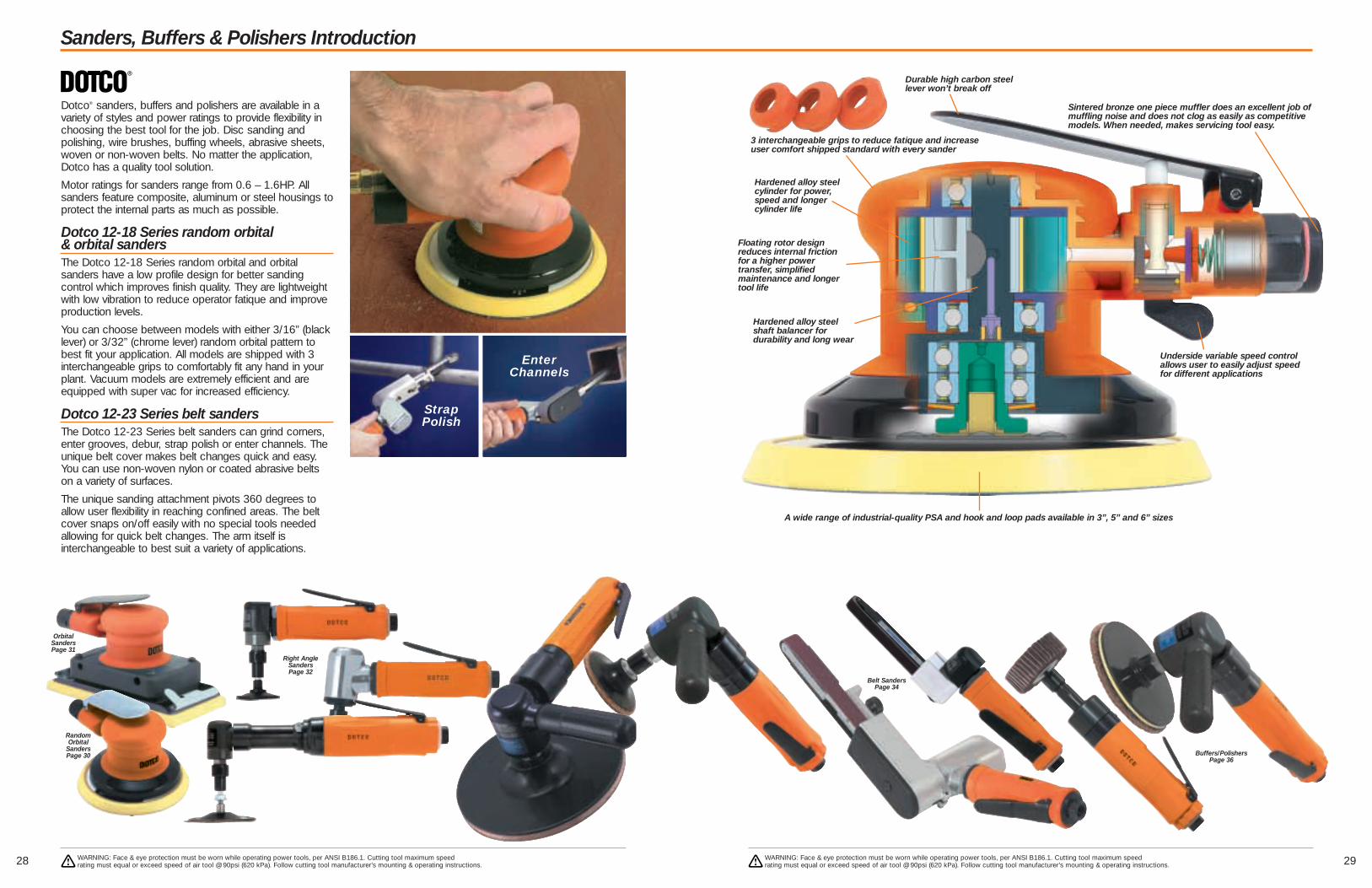
Dotco® sanders, buffers and polishers are available in avariety of styles and power ratings to provide flexibility inchoosing the best tool for the job. Disc sanding andpolishing, wire brushes, buffing wheels, abrasive sheets,woven or non-woven belts. No matter the application,Dotco has a quality tool solution.
Motor ratings for sanders range from 0.6 – 1.6HP. Allsanders feature composite, aluminum or steel housings toprotect the internal parts as much as possible.
Dotco 12-18 Series random orbital & orbital sandersThe Dotco 12-18 Series random orbital and orbitalsanders have a low profile design for better sandingcontrol which improves finish quality. They are lightweightwith low vibration to reduce operator fatique and improveproduction levels.
You can choose between models with either 3/16” (blacklever) or 3/32” (chrome lever) random orbital pattern tobest fit your application. All models are shipped with 3interchangeable grips to comfortably fit any hand in yourplant. Vacuum models are extremely efficient and areequipped with super vac for increased efficiency.
Dotco 12-23 Series belt sandersThe Dotco 12-23 Series belt sanders can grind corners,enter grooves, debur, strap polish or enter channels. Theunique belt cover makes belt changes quick and easy.You can use non-woven nylon or coated abrasive beltson a variety of surfaces.
The unique sanding attachment pivots 360 degrees toallow user flexibility in reaching confined areas. The beltcover snaps on/off easily with no special tools neededallowing for quick belt changes. The arm itself isinterchangeable to best suit a variety of applications.
Durable high carbon steellever won’t break off
3 interchangeable grips to reduce fatique and increaseuser comfort shipped standard with every sander
Hardened alloy steelcylinder for power,speed and longercylinder life
Floating rotor designreduces internal frictionfor a higher powertransfer, simplifiedmaintenance and longertool life
Sintered bronze one piece muffler does an excellent job ofmuffling noise and does not clog as easily as competitivemodels. When needed, makes servicing tool easy.
Hardened alloy steelshaft balancer fordurability and long wear
Underside variable speed controlallows user to easily adjust speedfor different applications
A wide range of industrial-quality PSA and hook and loop pads available in 3”, 5” and 6” sizes
WARNING: Face & eye protection must be worn while operating power tools, per ANSI B186.1. Cutting tool maximum speed rating must equal or exceed speed of air tool @ 90psi (620 kPa). Follow cutting tool manufacturer’s mounting & operating instructions.
WARNING: Face & eye protection must be worn while operating power tools, per ANSI B186.1. Cutting tool maximum speed rating must equal or exceed speed of air tool @ 90psi (620 kPa). Follow cutting tool manufacturer’s mounting & operating instructions.
Strap Polish
Enter Channels
OrbitalSandersPage 31
RandomOrbital
SandersPage 30
Right AngleSandersPage 32
Belt SandersPage 34
Buffers/PolishersPage 36

3130
SandersRandom Orbital
SandersOrbital
12-18 SeriesNominal Motor Power
0.24 hp0.18 kW
■ Low profile for more sanding control
■ Lightest weight to reduce operatorfatique
■ Extremely efficient built-in vacuumsystem with swivel hose fittings
■ 3/16” & 3/32” random orbital pattern
■ Levers allow users to visually see thedifference between 3/16” and 3/32”machines
■ 3 interchangeable grips to fit all hand sizes
12L1820-15
12L1820-05
12L1823-05
12L1820-03
12L1820-1612L1820-25
GENERAL:Air Inlet: 1/4” NPT - Use 1/4” (6.4mm) I.D. HoseAll tools performance rated @90 psi (620 kPa) air pressureAir Flow: 16 SCFM (453 LPM) Power: 0.24 hp (179 W)
STANDARD EQUIPMENT:Operating instructions & parts manual.Random Orbital Models – 3/8” low profile medium density premium urethane back-up pad; Interchangeable grips (3)
OPTIONAL EQUIPMENT:See page 38 for back-up pads.
ADDITIONAL MODELS:+ Add “HL” to end of model number to designate hook and loop pad.
Refer to Page 7 for description of Rapid Select.
3/16” 3/32”
Model Number Sanding Free Speed Weight Height Length3/16” Orbit 3/32” Orbit Pad Size rpm lb. kgs. in. mm in. mm
12-18 Series – Random Orbital Sander – Non Vacuum12L1820-03 3.5” 12,000 1.56 0.71 3.33 84.58 5.11 129.79
12L1820-05+ 12L1823-05+ 5.0” 12,000 1.62 0.73 3.33 84.58 5.48 139.1912L1820-06+ 12L1823-06 6.0” 12,000 1.68 0.76 3.33 84.58 5.48 139.19
12-18 Series – Random Orbital Sander – Central Vacuum, Vacuum Attachment & Shroud12L1820-13 3.5” 12,000 1.60 0.73 3.33 84.58 6.98 177.29
12L1820-15+ 12L1823-15 5.0” 12,000 1.73 0.78 3.33 84.58 7.75 196.8512L1820-16+ 6.0” 12,000 1.90 0.86 3.33 84.58 7.75 196.85
12-18 Series – Random Orbital Sander – Self-Generated Unit with Vacuum Hose & Floor Bag12L1820-25+ 5.0” 12,000 1.73 0.78 3.33 84.58 8.33 211.5812L1820-26+ 6.0” 12,000 1.80 0.82 3.33 84.58 8.84 224.54
12-18 Series
Nominal Motor Power0.24 hp / 0.18 kW
■ Lightest weight full size orbital inthe world
■ Full 10,000 OPM with more powerand faster cutting than anyequivalent machine
■ Patent pending pad suspensionsystem that produces unmatchedperformance
■ 3 interchangeable grips to fit all hand sizes
■ 3/16” orbital pattern
Model Number Abrasive Speed Weight Height Length Width
Clip PSA Hook & Loop Size orbits/minute lbs. kg in. mm in. mm in. mm
12-18 Series – 3/16” Orbital Sander – Non-Vacuum12L1850-09 3.66” x 9” 10,000 2.28 1.03 3.94 100.01 6.88 174.63 3.53 89.69
12L1850-07 12L1850-07HL 3.66” x 7” 10,000 2.20 1.00 3.94 100.01 6.88 174.63 3.53 89.6912-18 Series – 3/16” Orbital Sander – Central Vacuum
12L1850-19 12L1850-17 3.66” x 7” 10,000 2.20 1.00 3.94 100.01 8.78 223.04 3.53 89.6912-18 Series – 3/16” Orbital Sander – Self-Generated Unit with Vacuum Hose & Floor Bag
12L1850-27 3.66” x 7” 10,000 2.37 1.08 3.94 100.01 10.00 254.00 3.53 89.69
GENERAL:Air Inlet: 1/4” NPT - Use 1/4” (6.4mm) I.D. HoseAll tools performance rated @90 psi (620 kPa) air pressureAir Flow: 16 SCFM (453 LPM) Power: 0.24 hp (179 W)STANDARD EQUIPMENT:Operating instructions & parts manual.Orbital Models – back-up pad.Interchangeable grips (3)
OPTIONAL EQUIPMENT:See page 38 for back-up pads.
Refer to Page 7 for description of Rapid Select.
12L1850-09
12L1850-27
WARNING: Face & eye protection must be worn while operating power tools, per ANSI B186.1. Cutting tool maximum speed rating must equal or exceed speed of air tool @ 90psi(620 kPa). Follow cutting tool manufacturer’s mounting & operating instructions. Tools must be equipped with lock-off lever to be CE compliant.
WARNING: Face & eye protection must be worn while operating power tools, per ANSI B186.1. Cutting tool maximum speed rating must equal or exceed speed of air tool @ 90psi(620 kPa). Follow cutting tool manufacturer’s mounting & operating instructions. Tools must be equipped with lock-off lever to be CE compliant.
12L1850-17

12-22
3332
Right Angle SandersFor Disc Sanding & Polishing
Right Angle SandersFor Disc Sanding & Polishing
12-12 & 10-12 Series – 0.3 hp (0.22 kW) – 300 Series Collet12L1201-36 12L1281-36 20,000 2” Sanding/Polishing Disc C 1.1 0.5 6.3 160 2.9 74 1/4” 1/4”12L1200-36 12L1280-36 12,000 3” Sanding/Polishing Disc C 1.1 0.5 6.3 160 2.9 74 1/4” 1/4”10L1201-36 10L1281-36 20,000 2” Sanding/Polishing Disc C 1.0 0.5 5.0 127 2.9 74 1/4” 1/4”10L1200-36 10L1280-36 12,000 3” Sanding/Polishing Disc C 1.0 0.5 5.0 127 2.9 74 1/4” 1/4”
12-12 & 10-12 Series – 0.3 hp (0.22 kW) – 1/4”-28 Internal Thread12L1201-32 12L1281-32 20,000 2” Sanding/Polishing Disc C 1.1 0.5 6.3 160 1.9 48 1/4”-28 1/4”12L1200-32 12L1280-32 12,000 3” Sanding/Polishing Disc C 1.1 0.5 6.3 160 1.9 48 1/4”-28 1/4”10L1200-32 12,000 3” Sanding/Polishing Disc C 1.0 0.5 5.0 127 1.9 48 1/4”-28 1/4”10B1200-32 12,000 3” Sanding/Polishing Disc C 1.0 0.5 5.0 127 1.9 48 1/4”-28 1/4”
12-13 Series – 0.3 hp (0.22 kW) – Gearless – 300 Series Collet12L1380-36 30,000 1” Sanding/Polishing Disc C 1.1 0.5 7.1 180 3.9 99 1/4” 1/4”12L1381-36 25,000 2” Sanding/Polishing Disc C 1.1 0.5 7.1 180 3.9 99 1/4” 1/4”12L1382-36• 20,000 2” Sanding/Polishing Disc C 1.1 0.5 7.1 180 3.9 99 1/4” 1/4”
12-22 Series – 0.6 hp (0.45 kW) – 300 Series Collet – Heavy Duty Head12L2218-36 18,000 3” Sanding/Polishing Disc C 1.7 0.8 7.5 191 2.7 69 1/4” 1/4”
12-22 Series – 0.6 hp (0.45 kW) – 5/8”-11 Threaded Spindle – Heavy Duty Head12L2251-80• 9,000 5” Sanding/Polishing Disc C 3.2 1.5 9.3 236 3.9 99 5/8-11” 1/4”
12-27 Series – 0.9 hp (0.67 kW) - 5/8” – 11 Threaded Spindle – Heavy Duty Head12L2752-80 11,000 4” Sanding/Polishing Disc C 3.4 1.5 9.8 249 3.9 99 5/8”-11” 1/4”12L2751-80 9,000 5” Sanding/Polishing Disc C 3.4 1.5 9.8 249 3.9 99 5/8”-11” 1/4”12L2750-80 6,000 7” Sanding/Polishing Disc C 3.4 1.5 9.8 249 3.9 99 5/8”-11” 1/4”12L2762-80• 4,500** 7” Sanding/Polishing Disc C 3.3 1.5 10.5 267 3.9 99 5/8”-11” 1/4”12L2761-80• 6,000** 7” Sanding/Polishing Disc C 3.3 1.5 10.5 267 3.9 99 5/8”-11” 1/4”12L2760-80• 3,300** 7” Sanding/Polishing Disc C 3.3 1.5 10.5 267 3.9 99 5/8”-11” 1/4”
10-27 Series – 0.9 hp (0.67 kW) - 5/8” – 11 Threaded Spindle – Heavy Duty Head10L2751-80 9,000 5” Sanding/Polishing Disc A 3.1 1.4 8.5 216 3.9 99 5/8”-11” 1/4”10L2750-80 6,000 7” Sanding/Polishing Disc A 3.1 1.4 8.5 216 3.9 99 5/8”-11” 1/4”
1,250 – 30,000 RPM
0.3 – 1.7 hp (0.22 – 1.27 kW)
■ Suitable for a wide range offinishing and sandingapplications
■ Geared or gearless models
■ Front, side, and rear exhaustmodels
■ Composite or aluminum housing
■ Choice governed or non-governed models
WARNING: Face & eye protection must be worn while operating power tools, per ANSI B186.1. Cutting tool maximum speed rating must equal or exceed speed of air tool @ 90psi(620 kPa). Follow cutting tool manufacturer’s mounting & operating instructions. Tools must be equipped with lock-off lever to be CE compliant.
WARNING: Face & eye protection must be worn while operating power tools, per ANSI B186.1. Cutting tool maximum speed rating must equal or exceed speed of air tool @ 90psi(620 kPa). Follow cutting tool manufacturer’s mounting & operating instructions. Tools must be equipped with lock-off lever to be CE compliant.
12-12
1O-12
12-13Gearless
12-22
12-22Heavy Duty
Head
Free Head Collet/ AirModel Number Speed Type Weight Length Height* Spindle Inlet
Front Exhaust Side Exhaust Rear Exhaust rpm Disc Capacity Housing lbs. kgs in. mm in. mm Size Size
Housing Guide: A=Aluminum, C=Composite, S=Steel* Over spindle**Governor controlled speeds• Oilless bladesGENERAL:All tools performance rated @ 90psi (620 kPa) air pressure.Minimum Hose I.D.– 12-12, 10-12, 12-13 Series: 1/4” (4.8mm)
12-22, 12-27, 10-27, Series: 5/16” (7.9mm)12-42 Series: 1/2” (12.7mm)
STANDARD EQUIPMENT:Applicable collet, collet wrenches12-13 tools also include grease gun and gear lubeEXTRA EQUIPMENT:For lock-off safety lever, substitute “S” for “L” in model number.Collets: See page 26Overhose (rear exhaust): See page 63
Refer to Page 7 for description of Rapid Select.
10-27Heavy Duty
Head
New! Ergonomic Safety LeverBeginning July 2004, all Dotco“S” tools will be shipped with ournew comfort grip safety lever.

3534
Belt SandersFor Woven & Non-Woven Sanding Belts
Belt SandersFor Woven & Non-Woven Sanding Belts
12,000 – 20,000 RPM
0.3 – 0.5 hp (0.22 – 0.38 kW)
■ Grind, debur, strap polish, blend
■ Choice of geared or gearless
■ Ergonomic housing reduces coldair transmission to operator
■ 12-23 model acceptsinterchangeable arms
Free AirModel Number Speed Type Contact Weight Length Inlet
Front Exhaust Rear Exhaust rpm Belt Capacity Housing Arm lbs. kgs. in. mm Size
12-12* Series – 0.3 hp (0.22 kW) – Sanding Belt12L1281-36B2 20,000 1/2”W x 12”L Sanding Belt C Straight 1.4 0.6 11.3 287 1/4”12L1280-36B2 12,000 1/2”W x 12”L Sanding Belt C Straight 1.4 0.6 11.3 287 1/4”
12-13* Series – 0.3 hp (0.22 kW) – Gearless – Sanding Belt12L1382-36B2• 20,000 1/2”W x 12”L Sanding Belt C Straight 1.4 0.6 11.3 287 1/4”12L1382-36B4• 20,000 1”W x 12”L Sanding Belt C Straight 1.7 0.8 11.3 287 1/4”
12-23 Series - 0.5 hp (0.38 kW) – Gearless – Woven or Non-Woven Belt12L2384-B1 20,000 5/8”or 3/4”W x 18”L Belt C Straight 2.5 1.1 15.0 381 1/4”12L2384-K1 (Kit) 20,000 (See details below) C Straight/Offset 2.5 1.1 15.0 381 1/4”
12-12
Housing Guide: A=Aluminum, C=Composite, S=Steel• Oilless blades
GENERAL:All tools performance rated @ 90psi (620 kPa) air pressure.Minimum Hose I.D. 1/4” (6.4mm)
STANDARD EQUIPMENT:12-12, 12-13 series: No.80 and No.120 grit sanding belt or one mediumgrit non-woven belt, applicable wrenches, grease gun, gear lube 12-23 series: Tool and contact arm, adjustment wrench.
EXTRA EQUIPMENT:For lock-off safety lever, substitute “S” for “L” in model number.Overhose (rear exhaust): See pg. 63Attachments: See pg. 40OPTIONAL EQUIPMENT:See pg. 38 for additional belts.
*OPTIONAL TERMINATIONS FOR 12-12 & 12-13 SERIES(All models may not be available):-32Bx 1/4”-28 Internal Thread; -36Bx 1/4” collet
Refer to Page 7 for description of Rapid Select.
12-23
Kit includes the following:Tool with 3/4” wide straight arm (1) Additional Arms (2)
1 – 1/2” wide straight arm1 – offset arm
1/4” x 18” Aluminum Oxide Belts (3)1 – 60 grit1 – 80 grit1 – 120 grit
1/2” x 18” Aluminum Oxide Belts (3)1 – 60 grit1 – 80 grit1 – 120 grit
3/4” x 18” Aluminum Oxide Belts (2) 1 – 60 grit1 – 80 grit
3/4” x 18” Non-Woven Belt (1) Medium
Wrenches & Misc. Items1 – 3/4” open end wrench1 – 9/16” open end wrench1 – 9/64” hex wrench1 – 3/16” hex wrench1 – 1/4” collet1 – collet cap1 – chuck body
Carrying Case w/Foam Inserts (1)
Strap Polish
Enter Channels
WARNING: Face & eye protection must be worn while operating power tools, per ANSI B186.1. Cutting tool maximum speed rating must equal or exceed speed of air tool @ 90psi(620 kPa). Follow cutting tool manufacturer’s mounting & operating instructions. Tools must be equipped with lock-off lever to be CE compliant.
WARNING: Face & eye protection must be worn while operating power tools, per ANSI B186.1. Cutting tool maximum speed rating must equal or exceed speed of air tool @ 90psi(620 kPa). Follow cutting tool manufacturer’s mounting & operating instructions. Tools must be equipped with lock-off lever to be CE compliant.
12-13
Dotco 12L2384-K1 KitWhen you order the Dotco 12L2384-K1 kit you get the tooland all three interchangeable arms, belts and wrenches. You’llbe ready for just about any finishing project using the Dotco12L2384-K1 kit.
New! Ergonomic Safety LeverBeginning July 2004, all Dotco“S” tools will be shipped with ournew comfort grip safety lever.

3736
Buffers/PolishersFor Wire Brushes, Buffing Wheels and Abrasive Sheets
Buffers/PolishersFor Wire Brushes, Buffing Wheels and Abrasive Sheets
2,200 – 6,200 RPM
0.3 – 1.7 hp (0.22 – 1.27 kW)
■ Many models to choose from tomeet your application needs
■ Front, side, and rear exhaust
12-10 Series – 0.3 hp (.22 kW) – 200 Series Collet12L1093-01 5,000 3” 3” C 1.6 0.7 7.2 183 1/4” 1/4”12L1092-01 3,200 3” 3” C 1.6 0.7 7.2 183 1/4” 1/4”
12- 25 Series – 0.9 hp (.67 kW) – 200 Series Collet12L2594-01 6,200 4” 6” C 2.1 0.9 9.3 236 1/4” 1/4”12L2593-01 4,700 4” 6” C 2.1 0.9 9.3 236 1/4” 1/4”12L2592-01 3,200 4” 6” C 2.1 0.9 9.3 236 1/4” 1/4”
12-27 & 10-27 Series – 0.9 hp (.67 kW) – 5/8”-11 Threaded Spindle12L2762-80• 4,500* 4” 6” C 3.3 1.5 10.5 267 3.9 98 5/8”-11 1/4”12L2760-80• 3,300* 4” 6” C 3.3 1.5 10.5 267 3.9 98 5/8”-11 1/4”10L2760-80 3,300* 4” 6” A 3.9 1.8 9.3 236 3.9 98 5/8”-11 1/4”
12-42 Series – 1.7 hp (1.27 kW) - 5/8”-11 External Threaded Spindle12L4203-80• 3,400 4” 8” C 6.4 2.9 13.6 346 3.9 98 5/8”-11 1/2”
Housing Guide: A=Aluminum, C=Composite, S=Steel*Governor controlled speeds **Over spindle •Oilless bladesGENERAL:All tools performance rated @ 90psi (620 kPa) air pressure.Minimum Hose I.D.– 12-10 Series: 1/4” (6.4mm)
12-25, 12-27, 10-27, Series: 5/16” (7.9mm)12-42 Series: 1/2” (12.7mm)
STANDARD EQUIPMENT:12-10, 12-25: Applicable collet, collet wrenches 10-27, 12-27: Spindle wrench12-42: Nut, washer, spacer and wrenches.
EXTRA EQUIPMENT:For lock-off safety lever, substitute “S” for “L” in model number.Collets: See page 26Overhose (rear exhaust): See page 62Dead Handle: (12-10 models) 6188 Dead Handle: (12-25 Models) 8088
Refer to Page 7 for description of Rapid Select.
12-10
12-25
Free Capacity Head Collet/ AirModel Number Speed Wire Buffing Type Weight Length Height** Spindle Inlet
Front Exhaust Side Exhaust Rear Exhaust rpm Brush Wheel Housing lbs. kgs in. mm in. mm Size Size
12-27
10-27
WARNING: Face & eye protection must be worn while operating power tools, per ANSI B186.1. Cutting tool maximum speed rating must equal or exceed speed of air tool @ 90psi(620 kPa). Follow cutting tool manufacturer’s mounting & operating instructions. Tools must be equipped with lock-off lever to be CE compliant.
WARNING: Face & eye protection must be worn while operating power tools, per ANSI B186.1. Cutting tool maximum speed rating must equal or exceed speed of air tool @ 90psi(620 kPa). Follow cutting tool manufacturer’s mounting & operating instructions. Tools must be equipped with lock-off lever to be CE compliant.
New! Ergonomic Safety LeverBeginning July 2004, all Dotco“S” tools will be shipped with ournew comfort grip safety lever.

PSA Disc HoldersCollet Chuck:Chuck the PSA disc holder shank directly into the appropriate collet (1/8” or 1/4”).
Threaded Spindle:Remove the threaded shank from the PSA disc holder. Referring tothe spindle adapter chart, select the correct spindle and thread itinto the PSA holder.
Sander Accessories
39
Sander Accessories
38
Low Profile Backup Pads for Random Orbital SandersA thinner, harder pad generally recommended for aggressive sanding and leveling of flat surfaces.
PSA Pads Hook & Loop PadsDiameter Thickness Non-Vacuum Vacuum Non-Vacuum Vacuum
3 1/2” 3/8” 543025 543025 543026 5430265” 3/8” 543017 543018 543019 5430206” 3/8” 543021 543022 543023 543024
Tapered Edge Backup Pads for Random Orbital SandersA thicker, softer pad generally recommended for contour sanding and feather edging.
PSA PadsDiameter Thickness Non-Vacuum
5” 3/4” 5430416” 3/4” 543042
Backup Pads for Orbital SandersPSA adhesion to tool eliminates the need for any tools when changing pads. Pad remains flat throughout full orbit at any speed.
PSA Pads Hook & Loop PadsDiameter Thickness Non-Vacuum Vacuum Non-Vacuum Vacuum
3-2/3”x7” 3/8” 543011 – – 543014
543017 543024
543025
543042
543014
Belt Sander AttachmentsDotco 12-12 and 12-13 series.
Non-woven Attachments (used with 12,000 rpm 12-12 series)
14-1715 – 1/2” x 18” 13 x 457 1/2” x 6” 13 x 152
Coated Abrasive Attachments (used with 12,000 rpm 12-12 series; 20,000 rpm 12-12 & 12-13 series)
14-1639 14-1638 1/4” x 12” 6.4 x 305 1/4” x 4” 6.4 x 10214-1316 14-1301 1/2” x 12” 13 x 305 1/2” x 4” 13 x 10214-1473 14-1463 1” x 12” 25 x 305 1” x 4” 25 x 10214-1319 14-1318 1/2” x 24” 13 x 610 1/2” x 10” 13 x 25414-1613 14-1603 1” x 24” 25 x 610 1” x 10” 25 x 254
Sanding Belts – Aluminum Oxide, Resin BondFor use with Dotco belt sanders. Minimum order: 10 of any one belt.
40 14-134450 14-134560 14-1590 14-1346 14-1582 14-1366 14-1642 14-2320 14-2316 14-232680 14-1591 14-1348 14-1583 14-1368 14-2321 14-2317 14-2323100 14-1350120 14-1593 14-1352 14-1585 14-1372 14-2322 14-2318150 14-1355180 14-1596 14-1358 14-1588 14-1378 14-1648240 14-1360320 14-1362
Belt NumberGrit Size
1/4” x 12 1/2” x 12 1” x 12 1/2” x 24 1” x 24 1/4” x 18 1/2” x 18 3/4” x 18
Sanding Belts – Non-wovenMinimum order: 10 of any one belt.
Extra Fine 14-1728Fine 14-1729
Medium 14-1730 14-2327Coarse 14-1731
Part NumberGrit Size
1/4” x 18 3/4” x 18
Flexible 14-2197 14-2255 14-2115 14-2529 14-2202Medium 14-2198 14-2256 14-2116 14-2200 14-2203Rigid 14-2199 14-2257 14-2117 14-2201
Spiralcool™ Backing PadsFor Dotco sanders with 5/8”-11 threaded spindles. Pad contour develops draftaction to cool disc and avoid excessive pick-up.
Part Number – Pad Diameter (Max. rated RPM)Flexibility 4” 4 1/2” 5” 7” 9”
12,000 rpm 11,000 rpm 10,000 rpm 7,000 rpm 6,000 rpm 14-2118 5/8”-11 threaded spindle
Sanding Pad NutFor use with Dotco sanders with 5/8”-11threaded spindles.
14-2319 5/8”-11 threaded spindle
Spanner WrenchFor use with 14-2118Sanding Nut Pad.
5” 7,500 14-2515 14-2521 14-2522 14-25257” 7,500 14-2517 14-2521 14-2523 14-25259” 7,500 14-2519 14-2521 14-2525
Save-A-Disc PadsFor Dotco sanders with 5/8”-11 threaded spindles. Ribs on the backing plate cause a flexing action which throws off accumulation.
Part NumberDiameter
Maximum rpm Assembly Pad Only Plate Only Nut Only
* NOTE: For 1/4”-28 internal thread** NOTE: For 5/16”-24 internal thread – 1/8” collet
*** NOTE: For 3/8”-24 internal thread – 1/4” collet
Part Number Description
14-2535 Disc CutterReplacement Blades14-2590 Upper14-2591 Lower
Sanding Disc CutterAn adjustment scale allows a 9” maximum diametersanding disc to be cut down to 3” or 4” diameter.The double bevel cutting edge assures a round cutwithout a loose edge or raveling.
Part Number Tool Series
Part Number Tool Series
Part NumberShank Size
Assembly Collet
1/8” 14-1102* 14-0158**1/4” 14-1104* 14-0168***6 mm 14-1094 14-0170***
Mini ChucksFor use with Dotco 12-12 series. To adapt right angle threaded spindle sanders for drilling, disc sanding with PSA holders, and light grinding.
Disc Holder Shank PSA DiscPart Number Diameter Assembly Holder Thread
14-1146 1/2” 1/8” 5-40 Female14-1105 1/2” 1/4” 5-40 Female14-1147 3/4” 1/8” 5-40 Female14-1107 3/4” 1/4” 5-40 Female14-1170 1” 1/8” 5-40 Female14-1110 1” 1/4” 5-40 Female14-1111 1-1/2” 1/4” 1/4”-20 Female14-1112 2” 1/4” 1/4”-20 Female14-1113 3” 1/4” 1/4”-20 Female14-1114 4” 1/4” 1/4”-20 Female
Adapter DescriptionPart Number Thread (for Thread (for PSA Maximum
Tool Spindle) Disc Holder) Disc Diameter
14-1142 1/4”-28 Male 5 -40 Male 1”14-1144 1/4”-28 Male 1/4”-20 Male 4”14-2903 5/8”-11 Male 5/16”-24 Male 4”14-1212 5/8”-11 Male 1/4”-20 Male 4”14-1211 5/8”-11 Female 3/8”-24 Male 4”
Spindle AdaptersFor use with PSA Disc holders.
14-2517
14-1112
14-1144
14-1104
WARNING: Face & eye protection must be worn while operating power tools, per ANSI B186.1. Cutting tool maximum speed rating must equal or exceed speed of air tool @ 90psi(620 kPa). Follow cutting tool manufacturer’s mounting & operating instructions. Tools must be equipped with lock-off lever to be CE compliant.
WARNING: Face & eye protection must be worn while operating power tools, per ANSI B186.1. Cutting tool maximum speed rating must equal or exceed speed of air tool @ 90psi(620 kPa). Follow cutting tool manufacturer’s mounting & operating instructions. Tools must be equipped with lock-off lever to be CE compliant.
300 Series Collet 1/4”-28 Int. Thread Sanding Belt Size Sanding Area
-36 Termination -32 Termination in. mm in. mm
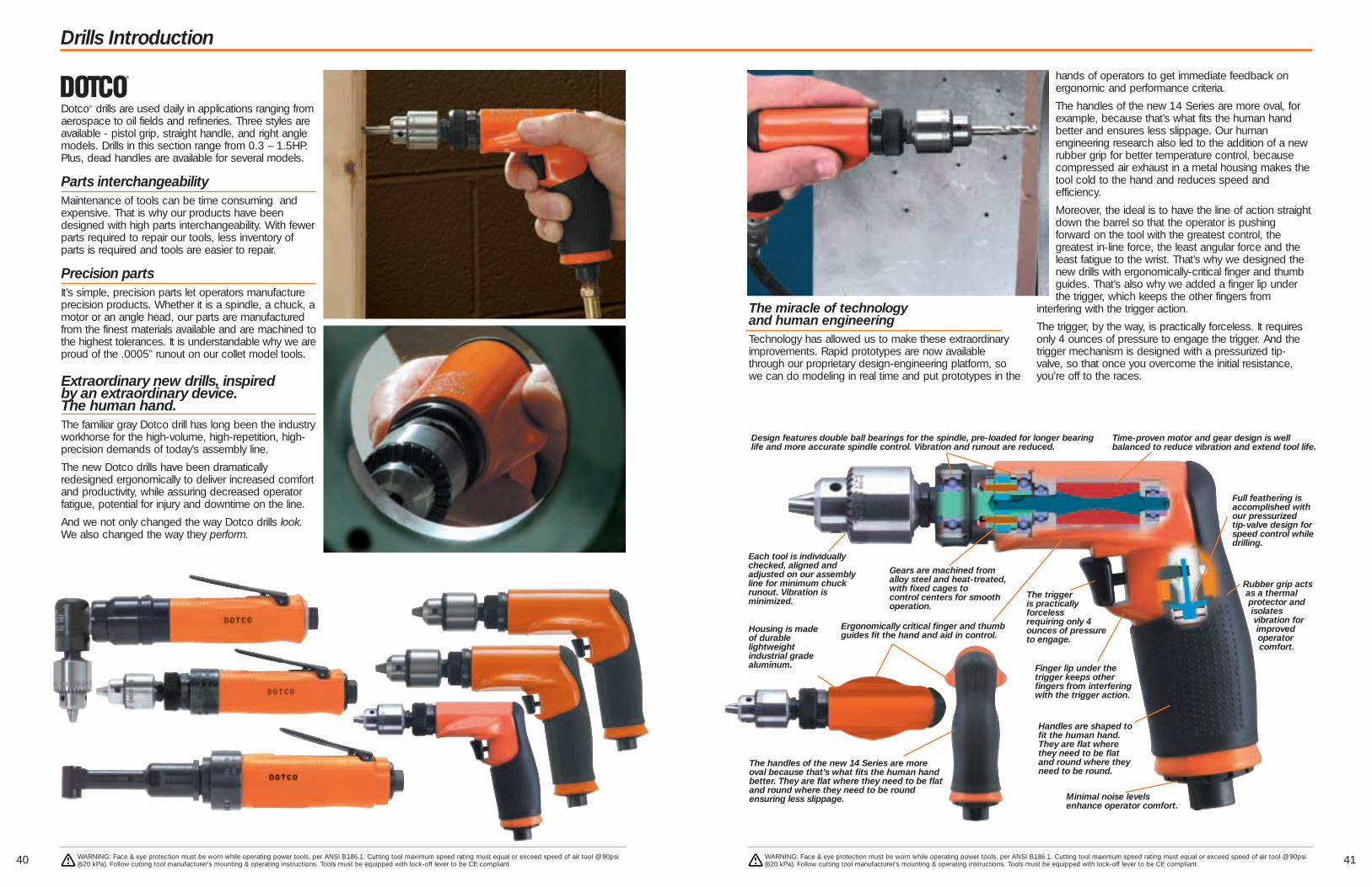
The miracle of technology and human engineeringTechnology has allowed us to make these extraordinaryimprovements. Rapid prototypes are now availablethrough our proprietary design-engineering platform, sowe can do modeling in real time and put prototypes in the
hands of operators to get immediate feedback onergonomic and performance criteria.
The handles of the new 14 Series are more oval, forexample, because that’s what fits the human handbetter and ensures less slippage. Our humanengineering research also led to the addition of a newrubber grip for better temperature control, becausecompressed air exhaust in a metal housing makes thetool cold to the hand and reduces speed andefficiency.
Moreover, the ideal is to have the line of action straightdown the barrel so that the operator is pushingforward on the tool with the greatest control, thegreatest in-line force, the least angular force and theleast fatigue to the wrist. That’s why we designed thenew drills with ergonomically-critical finger and thumbguides. That’s also why we added a finger lip underthe trigger, which keeps the other fingers from
interfering with the trigger action.
The trigger, by the way, is practically forceless. It requiresonly 4 ounces of pressure to engage the trigger. And thetrigger mechanism is designed with a pressurized tip-valve, so that once you overcome the initial resistance,you’re off to the races.
41
Drills Introduction
40
Dotco® drills are used daily in applications ranging fromaerospace to oil fields and refineries. Three styles areavailable - pistol grip, straight handle, and right anglemodels. Drills in this section range from 0.3 – 1.5HP.Plus, dead handles are available for several models.
Parts interchangeabilityMaintenance of tools can be time consuming andexpensive. That is why our products have beendesigned with high parts interchangeability. With fewerparts required to repair our tools, less inventory ofparts is required and tools are easier to repair.
Precision partsIt’s simple, precision parts let operators manufactureprecision products. Whether it is a spindle, a chuck, amotor or an angle head, our parts are manufacturedfrom the finest materials available and are machined tothe highest tolerances. It is understandable why we areproud of the .0005” runout on our collet model tools.
Extraordinary new drills, inspired by an extraordinary device. The human hand. The familiar gray Dotco drill has long been the industryworkhorse for the high-volume, high-repetition, high-precision demands of today’s assembly line.
The new Dotco drills have been dramaticallyredesigned ergonomically to deliver increased comfortand productivity, while assuring decreased operatorfatigue, potential for injury and downtime on the line.
And we not only changed the way Dotco drills look.We also changed the way they perform.
Full feathering is accomplished withour pressurized tip-valve design forspeed control whiledrilling.
Minimal noise levelsenhance operator comfort.
The trigger is practically forcelessrequiring only 4ounces of pressureto engage.
Finger lip under thetrigger keeps other fingers from interferingwith the trigger action.
Design features double ball bearings for the spindle, pre-loaded for longer bearinglife and more accurate spindle control. Vibration and runout are reduced.
Time-proven motor and gear design is well balanced to reduce vibration and extend tool life.
Rubber grip actsas a thermalprotector andisolates vibration forimprovedoperatorcomfort.
WARNING: Face & eye protection must be worn while operating power tools, per ANSI B186.1. Cutting tool maximum speed rating must equal or exceed speed of air tool @ 90psi(620 kPa). Follow cutting tool manufacturer’s mounting & operating instructions. Tools must be equipped with lock-off lever to be CE compliant.
WARNING: Face & eye protection must be worn while operating power tools, per ANSI B186.1. Cutting tool maximum speed rating must equal or exceed speed of air tool @ 90psi(620 kPa). Follow cutting tool manufacturer’s mounting & operating instructions. Tools must be equipped with lock-off lever to be CE compliant.
Each tool is individuallychecked, aligned and adjusted on our assemblyline for minimum chuckrunout. Vibration is minimized.
Gears are machined fromalloy steel and heat-treated,with fixed cages to control centers for smoothoperation.
Ergonomically critical finger and thumbguides fit the hand and aid in control.
Housing is madeof durable lightweight industrial gradealuminum.
Handles are shaped tofit the human hand.They are flat wherethey need to be flatand round where theyneed to be round.
The handles of the new 14 Series are moreoval because that’s what fits the human handbetter. They are flat where they need to be flatand round where they need to be round ensuring less slippage.

4342
Inline & Right Angle Drills Pistol Grip Drills
500 – 28,500 RPM
0.3 – 0.4 hp (0.22 – 0.30 kW)
■ Wide selection of tools to matchyour application
■ Rear exhaust
■ Select geared models available
Model Number Free Speed Drill Diameter Type Weight Length Head Ht. Chuck Air InletRear Exhaust rpm Capacity Housing lbs. kgs in. mm in. mm Size Size
Inline 15LF Series – 0.4 hp (0.30 kW)15LF081-38+ 5,300 1/4” C 1.4 0.6 8.0 203 - - 1/4” 1/4”15LF082-38+ 4,000 1/4” C 1.4 0.6 8.0 203 - - 1/4” 1/4”15LF083-38+ 3,300 1/4” C 1.4 0.6 8.0 203 - - 1/4” 1/4”15LF087-38+ 600 1/4” C 2.0 0.9 9.3 236 - - 1/4” 1/4”
Right Angle 15-14 Series – 0.3 hp (0.22 kW)15L1489-38 3,600* 1/4” C 1.5 0.7 8.0 203 3.0 76 1/4” 1/4”15L1488-38 2,400* 1/4” C 1.5 0.7 8.0 203 3.0 76 1/4” 1/4”
Housing Guide: A=Aluminum, C=Composite, S=Steel* Planetary geared+ Model available without chuck. Replace -38 with -40.
GENERAL:All Tools performance rated @ 90psi (620 kPa) air pressure.Minimum Hose I.D.– 15LF, 15-14 Series: 1/4” (6.4mm)
15-29 Series: 5/16” (7.9mm)
STANDARD EQUIPMENT:Jacobs geared chuck, chuck key, dead handle (all inline models withchuck size greater than 1/4”).EXTRA EQUIPMENT:For lock-off safety lever, substitute “S” for “L” in model number.Overhose (rear exhaust): See page 63Dead Handle: 539602
Refer to Page 7 for description of Rapid Select.
WARNING: Face & eye protection must be worn while operating power tools, per ANSI B186.1. Cutting tool maximum speed rating must equal or exceed speed of air tool @ 90psi(620 kPa). Follow cutting tool manufacturer’s mounting & operating instructions. Tools must be equipped with lock-off lever to be CE compliant.
WARNING: Face & eye protection must be worn while operating power tools, per ANSI B186.1. Cutting tool maximum speed rating must equal or exceed speed of air tool @ 90psi(620 kPa). Follow cutting tool manufacturer’s mounting & operating instructions. Tools must be equipped with lock-off lever to be CE compliant.
New! Ergonomic Safety LeverBeginning July 2004, all Dotco“S” tools will be shipped with ournew comfort grip safety lever.
GENERAL:See page 41 for additional features and benefits.Air Inlet: 1/4” NPT – Use 5/16” (7.9mm) I.D. hose.All Tools performance rated @ 90psi (620 kPa) air pressure.STANDARD EQUIPMENT:14CF: Jacobs geared chuck, chuck key
14CS, 14CN: Jacobs geared chuck, chuck key, dead handle (All models with a chuck opening greater than 1/2”)
EXTRA EQUIPMENT:Overhose: See pg. 63
Refer to Page 7 for description of Rapid Select.
330 – 29,000 RPM0.4 – 0.9 hp (0.30 – 0.67 kW)
■ Non-reversible■ Ergonomically critical finger and
thumb guides fit the hand to aid in control
■ Excellent for aerospace, metal fab and woodworking
Free Drill Geared AirModel Number Speed Diameter Weight** Length** Chuck InletWith Chuck Without Chuck rpm Capacity lbs. kgs in. mm Size Size
14CF Series – 0.4 hp (0.30 kW) – Non-reversible14CFS90-38 29,000 1/4” 1.5 0.68 5.7 145 3/8” 1/4”14CFS91-38 5,200 1/4” 1.5 0.68 5.7 145 3/8” 1/4”14CFS92-38 3,800 1/4” 1.5 0.68 5.7 145 3/8” 1/4”14CFS93-38 3,200 1/4” 1.5 0.68 5.7 145 3/8” 1/4”14CFS94-38 2,400 1/4” 1.6 0.72 5.7 145 3/8” 1/4”14CFS95-38 1,000 1/4” 1.8 0.82 6.9 175 3/8” 1/4”14CFS96-38 700 1/4” 1.8 0.82 6.9 175 3/8” 1/4”14CFS97-38 600 1/4” 1.8 0.82 6.9 175 3/8” 1/4”
14CS Series – 0.6 hp (0.45 kW) – Non-reversible14CSL90-38 14CSL90-40 20,000 1/4” 2.1 0.95 6.3 160 1/4” 1/4”14CSL98-38 14CSL98-40 6,000 1/4” 2.1 0.95 6.3 160 1/4” 1/4”14CSL91-38 14CSL91-40 5,200 1/4” 2.1 0.95 6.3 160 1/4” 1/4”14CSL92-38 14CSL92-40 3,200 1/4” 2.1 0.95 6.3 160 1/4” 1/4”14CSL95-51 14CSL95-40 1,300 3/8” 2.9 1.31 8.1 205 3/8” 1/4”14CSL97-51 14CSL97-40 500 3/8” 2.9 1.31 8.1 205 3/8” 1/4”
14CN Series – 0.9 hp (0.67 kW) – Non-reversible14CNL90-38 14CNL90-40 20,000 1/4” 2.2 1.00 6.8 173 1/4” 1/4”14CNL98-38 14CNL98-40 6,000 1/4” 2.2 1.00 6.8 173 1/4” 1/4”14CNL91-51 14CNL91-40 5,200 3/8” 2.4 1.08 7.2 183 3/8” 1/4”14CNL92-51 14CNL92-40 3,200 3/8” 2.4 1.08 7.2 183 3/8” 1/4”14CNL95-51 14CNL95-40 1,300 3/8” 2.8 1.27 8.6 218 3/8” 1/4”14CNL97-53 14CNL97-40 500 1/2” 3.5 1.59 9.1 231 1/2” 1/4”
14CF
14CS
14CN15LF
15-14

Variable Speed Drills
45
Drills
44
Speed Range:600 – 2600 rpm
Nominal Motor Power0.7 HP0.5 kW
m Sand Cast Handle
m Hardened Steel Back Cap
m Governed Speed Control
m Variable Speed
m Calibrated Speed Control
m Non-reversible
Model NumberSpeeds rpm Chuck Capacity* Length Weight
Free Governed in. mm in. mm lb. kg
0.7 hp (0.5 kW) – Variable Speed
135DPV-7B-43 600 150 - 550 3/8 10 9 5/8 244 3 5/8 1.6135DPV-7B-50 600 150 - 550 1/2 13 9 5/8 244 3 5/8 1.6135DPV-14B-50 1250 400 - 1200 1/2 13 9 1/4 235 3 3/8 1.5135DPV-14B-51 1250 400 - 1200 3/8 10 9 1/4 235 3 3/8 1.5135DPV-28B-51 2600 700 - 2400 3/8 10 8 1/2 216 3 1/8 1.4
GENERAL:Air Inlet: 1/4” NPTMinimum Hose Size: 1/4” (6mm)Spindle Offset: 25/32” (20mm)Tool performance rated at 90 psi (620kPa) air pressure.
STANDARD EQUIPMENT:Operating instructions and service manual3-Jaw Chuck and Key
* CAPACITY CAUTION NOTE: 135DPV Drills must be equipped with support handle (861006) if1/2” (13mm) capacity chuck is specified.
CAUTION:High reaction torque may be experienced with any drill atbreakthrough. Caution must be exercised when using any cutting toolbecause of the possibility of the cutting tool bending or breaking.Cutting tool maximum speed rating must equal or exceed speed oftool. Eye protection must be worn while operating power tools.
Refer to page 7 for description of Rapid Select.
135 DPV-7B-43
136 DPV-28B-51
Speed Range:160 – 1400 rpm
Nominal Motor Power1.0 HP0.75 kW
m Trigger Start
m Non-reversible
Model NumberFree Speed Stall Torque Chuck Capacity* Length Weight
rpm ft. lb. Nm in. mm in. mm lb. kg
1.0 hp (0.67 kW) – Non-reversible15DP-1.6B-53 160 160† 217† 1/2 13 9 3/4 248 6 2.715DP-4B-53 400 44† 60.0† 1/2 13 8 1/2 216 5 1/2 2.515DP-8B-53 800 22 30.0 1/2 13 8 1/2 216 5 1/2 2.515DP-14B-49 1400 14 19.0 3/8 10 8 1/4 210 4 1/2 2.0
GENERAL:Air Inlet: 3/8” NPTFMinimum Hose Size: 3/8”Spindle Thread: 1/2”-20Spindle Offset: Pistol Grip: 31/32”
STANDARD EQUIPMENT:Operating instructions and service manualDead handles on all models except 15DP-14B3-Jaw Chuck and Key
Refer to page 7 for description of Rapid Select.
*CAPACITY CAUTION NOTE: Pistol Grip 15 Series Drills must be equipped with support handle(881580) when used with chucks larger than 3/8” capacity.†Theoretical stall torque based on gear reduction. These tools are intended for slow speed applications and not high torqueapplications. High maintenance should be expected if tools areoperated in their upper torque range.
CAUTION:High reaction torque may be experienced with any drill at break-through. Caution must be exercised when using any cutting toolbecause of the possibility of the cutting tool bending or breaking.Cutting tool maximum speed rating must equal or exceed speed oftool. Eye protection must be worn while operating power tools.
15DP-8B-53
15DP-14B-49
WARNING: Face & eye protection must be worn while operating power tools, per ANSI B186.1. Cutting tool maximum speed rating must equal or exceed speed of air tool @ 90psi(620 kPa). Follow cutting tool manufacturer’s mounting & operating instructions. Tools must be equipped with lock-off lever to be CE compliant.
WARNING: Face & eye protection must be worn while operating power tools, per ANSI B186.1. Cutting tool maximum speed rating must equal or exceed speed of air tool @ 90psi(620 kPa). Follow cutting tool manufacturer’s mounting & operating instructions. Tools must be equipped with lock-off lever to be CE compliant.
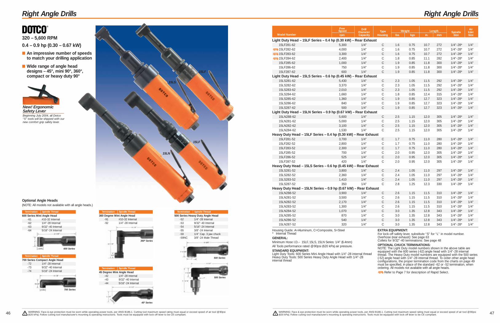
4746
Right Angle Drills Right Angle Drills
320 – 5,600 RPM
0.4 – 0.9 hp (0.30 – 0.67 kW)
■ An impressive number of speedsto match your drilling application
■ Wide range of angle headdesigns – 45°, mini 90°, 360°,compact or heavy duty 90°
Free Drill AirSpeed Diameter Type Weight Length Spindle InletModel Number rpm Capacity Housing lbs. kgs in. mm Size Size
Light Duty Head – 15LF Series – 0.4 hp (0.30 kW) – Rear Exhaust15LF281-62 5,300 1/4” C 1.6 0.75 10.7 272 1/4”-28* 1/4”15LF282-62 4,000 1/4” C 1.6 0.75 10.7 272 1/4”-28* 1/4”15LF283-62 3,300 1/4” C 1.6 0.75 10.7 272 1/4”-28* 1/4”15LF284-62 2,400 1/4” C 1.8 0.85 11.1 282 1/4”-28* 1/4”15LF285-62 1,000 1/4” C 1.9 0.85 11.8 300 1/4”-28* 1/4”15LF286-62 750 1/4” C 1.9 0.85 11.8 300 1/4”-28* 1/4”15LF287-62 600 1/4” C 1.9 0.85 11.8 300 1/4”-28* 1/4”
Light Duty Head – 15LS Series – 0.6 hp (0.45 kW) – Rear Exhaust15LS281-62 5,430 1/4” C 2.3 1.05 11.5 292 1/4”-28* 1/4”15LS282-62 3,370 1/4” C 2.3 1.05 11.5 292 1/4”-28* 1/4”15LS283-62 2,010 1/4” C 2.3 1.05 11.5 292 1/4”-28* 1/4”15LS284-62 1,660 1/4” C 1.8 0.85 12.4 315 1/4”-28* 1/4”15LS285-62 1,360 1/4” C 1.9 0.85 12.7 323 1/4”-28* 1/4”15LS286-62 840 1/4” C 1.9 0.85 12.7 323 1/4”-28* 1/4”15LS287-62 500 1/4” C 1.9 0.85 12.7 323 1/4”-28* 1/4”
Light Duty Head – 15LN Series – 0.9 hp (0.67 kW) – Rear Exhaust15LN288-62 5,600 1/4” C 2.5 1.15 12.0 305 1/4”-28* 1/4”15LN281-62 5,000 1/4” C 2.5 1.15 12.0 305 1/4”-28* 1/4”15LN282-62 3,100 1/4” C 2.5 1.15 12.0 305 1/4”-28* 1/4”15LN284-62 1,530 1/4” C 2.5 1.15 12.0 305 1/4”-28* 1/4”
Heavy Duty Head – 15LF Series – 0.4 hp (0.30 kW) – Rear Exhaust15LF281-52 3,700 1/4” C 1.7 0.75 11.0 280 1/4”-28* 1/4”15LF282-52 2,800 1/4” C 1.7 0.75 11.0 280 1/4”-28* 1/4”15LF283-52 2,300 1/4” C 1.7 0.75 11.0 280 1/4”-28* 1/4”15LF285-52 700 1/4” C 2.0 0.95 12.0 305 1/4”-28* 1/4”15LF286-52 525 1/4” C 2.0 0.95 12.0 305 1/4”-28* 1/4”15LF287-52 420 1/4” C 2.0 0.95 12.0 305 1/4”-28* 1/4”
Heavy Duty Head – 15LS Series – 0.6 hp (0.45 kW) – Rear Exhaust15LS281-52 3,800 1/4” C 2.4 1.05 11.0 297 1/4”-28* 1/4”15LS282-52 2,360 1/4” C 2.4 1.05 11.0 297 1/4”-28* 1/4”15LS283-52 1,410 1/4” C 2.4 1.05 11.0 297 1/4”-28* 1/4”15LS287-52 350 1/4” C 2.8 1.25 12.3 330 1/4”-28* 1/4”
Heavy Duty Head – 15LN Series – 0.9 hp (0.67 kW) – Rear Exhaust15LN288-52 3,900 1/4” C 2.6 1.15 11.5 310 1/4”-28* 1/4”15LN281-52 3,500 1/4” C 2.6 1.15 11.5 310 1/4”-28* 1/4”15LN282-52 2,170 1/4” C 2.6 1.15 11.5 310 1/4”-28* 1/4”15LN283-52 1,300 1/4” C 2.6 1.15 11.5 310 1/4”-28* 1/4”15LN284-52 1,070 1/4” C 3.0 1.35 12.8 343 1/4”-28* 1/4”15LN285-52 870 1/4” C 3.0 1.35 12.8 343 1/4”-28* 1/4”15LN286-52 540 1/4” C 3.0 1.35 12.8 343 1/4”-28* 1/4”15LN287-52 320 1/4” C 3.0 1.35 12.8 343 1/4”-28* 1/4”
Housing Guide: A=Aluminum, C=Composite, S=Steel* Internal ThreadGENERAL:Minimum Hose I.D.– 15LF, 15LS, 15LN Series: 1/4” (6.4mm)All Tools performance rated @ 90psi (620 kPa) air pressure.STANDARD EQUIPMENT:Light Duty Tools: 600 Series Mini Angle Head with 1/4”-28 internal threadHeavy Duty Tools: 500 Series Heavy Duty Angle Head with 1/4”-28internal thread
EXTRA EQUIPMENT:For lock-off safety lever, substitute “S” for “L” in model number.Overhose (rear exhaust): See page 63Collets for 9/32”-40 terminations: See page 48OPTIONAL CHUCK TERMINATIONS:NOTE: The Light Duty model numbers shown in the above table areequipped with the 600 series (-62) angle head with 1/4”-28 internalthread. The Heavy Duty model numbers are equipped with the 500 series(-52) angle head with 1/4”-28 internal thread. To order other angle headconfigurations, the proper termination code from the charts on page 49must be specified, in place of the standard -62 or -52 termination, whenordering. All models not available with all angle heads.
Refer to Page 7 for description of Rapid Select.
15LF
Termination Spindle Thread
Termination Spindle Thread
45 Degree Mini Angle Head-42 1/4”-28 Internal-43 9/32”-40 Internal-44 5/16”-24 Internal
360 Degree Mini Angle Head-91 #10-32 Internal-92 1/4”-28 Internal
360º Series
45º Series
Termination Spindle Thread
Termination Spindle Thread
600 Series Mini Angle Head-61 #10-32 Internal-62 1/4”-28 Internal-63 9/32”-40 Internal-64 5/16”-24 Internal
Optional Angle Heads(NOTE: All models not available with all angle heads.)
700 Series Compact Angle Head-72 1/4”-28 Internal-73 9/32”-40 Internal-74 5/16”-24 Internal
600 Series
700 Series
15LS
15LF
Termination Spindle Thread
500 Series Heavy Duty Angle Head-52 1/4”-28 Internal-53 9/32”-40 Internal-54 5/16”-24 Internal-55 3/8”-24 Internal-59 1/4” Cap. 3 jaw chuck-59NC 3/8”-24 Male Thread
500 Series
500 Series
15LN
WARNING: Face & eye protection must be worn while operating power tools, per ANSI B186.1. Cutting tool maximum speed rating must equal or exceed speed of air tool @ 90psi(620 kPa). Follow cutting tool manufacturer’s mounting & operating instructions. Tools must be equipped with lock-off lever to be CE compliant.
WARNING: Face & eye protection must be worn while operating power tools, per ANSI B186.1. Cutting tool maximum speed rating must equal or exceed speed of air tool @ 90psi(620 kPa). Follow cutting tool manufacturer’s mounting & operating instructions. Tools must be equipped with lock-off lever to be CE compliant.
New! Ergonomic Safety LeverBeginning July 2004, all Dotco“S” tools will be shipped with ournew comfort grip safety lever.

49
Drill Accessories Drill Accessories
48 WARNING: Face & eye protection must be worn while operating power tools, per ANSI B186.1. Cutting tool maximum speed rating must equal or exceed speed of air tool @ 90psi(620 kPa). Follow cutting tool manufacturer’s mounting & operating instructions. Tools must be equipped with lock-off lever to be CE compliant.
WARNING: Face & eye protection must be worn while operating power tools, per ANSI B186.1. Cutting tool maximum speed rating must equal or exceed speed of air tool @ 90psi(620 kPa). Follow cutting tool manufacturer’s mounting & operating instructions. Tools must be equipped with lock-off lever to be CE compliant.
Thread Size Capacity Part Number
3/8”-24 1/4” Hex 849414
Quick-Change Chuck
Drill Model Part Number
8 861006111 861006135 86100615 881580136 861006
Dead Handles
Drill Size Part Number
3/16” 8638101/4” 863806
Collet Chuck (1/4-28 Male Thread)
881580
1110164 1.375/1.3731110165 1.437/1.4351110166 1.501/1.4991110167 1.626/1.623
Quick ChangePressure Foot AdapterFor use on 1”-20 external thread toolsPart Number Diameter “A”
1005180 1/16 .0625 1.61005182 3/32 .0937 2.41005183 7/64 .1094 2.81005184 1/8 .125 3.21005185 9/64 .1406 3.61005186 5/32 .1562 4.01005187 11/64 .1719 4.41005188 3/16 .1875 4.81006408 53 .0595 1.51006412 51 .067 1.71005875 46 .081 2.11005684 40 .098 2.51006395 39 .0995 2.5
ColletsFor use on Dotco 15LF, 15LS & 15LN right angledrills with 9/32”-40 spindles. (Termination codes: - 43, -53, -63, -73, & -93)
Part Drill
Number Size Dec. mmPart Drill
Number Size Dec. mm
1005873 31 .120 3.01013904 30 .1285 3.31005872 27 .144 3.71006373 26 .147 3.71005926 22 .157 4.01005682 21 .159 4.01005876 20 .161 4.11006035 19 .166 4.21005977 17 .173 4.41005927 13 .185 4.71005871 12 .189 4.81006001 11 .191 4.91005681 10 .1935 4.9
* NOTE: For 1/4”-28 internal thread** NOTE: For 5/16”-24 internal thread – 1/8” collet***NOTE: For 3/8”-24 internal thread – 1/4” collet
Shank Size Assembly Collet
1/8” 14-1102* 14-0158**1/4” 14-1104* 14-0168***6 mm 14-1094 14-0170***
Mini ChucksFor use with DOTCO 12-12 series. To adapt right angle threaded spindle sanders for drilling, disc sanding with PSA holders, and light grinding.
14-11041110164
1005184
Part No. Description
1020699 1/4” capacity with a 1/4”-28 male thread
Cone Jaw Chuck
300 Series Collet ChuckUse with Standard Collet: 1/4” (#308).Termination Number: -36
14-1148 1/64”-1/4” capacity with a 5/16”-24 female thread
Jacobs ChucksThread
Part No. Size Capacity Description Term.
1005078 3/8”-24 1/4” 1 BA -381001505 3/8”-24 1/4” HD 7 BA -421110945 3/8”-24 3/8” Keyless (31073) -56863420 3/8”-24 3/8” 22 BA (lt. duty) -471004422 3/8”-24 3/8” 2 BA (med. duty) -431001252 3/8”-24 3/8” 41 BA (med. duty) -511009726 3/8”-24 1/2” 33 BA -531075 5/16”-24 5/32” *OB 37
Vacuum AttachmentFor use on Dotco pistol grip drills.
Small Handle Tools1025867 Shop Vac Shroud Only
Large Handle Tools1025867 Shop Vac Shroud Only1025891 Shroud, Venturi Vacuum Attachment & Bag
Optional Drill AttachmentsFor use on Dotco 15LF, 15LS, and 15LN series. Capacity: 1/4” Diameter DrillThese drill attachments can be ordered as a separate accessory item or as part of a complete model. To order as a complete model, use the basicmodel number from the appropriate 15LF, 15LS, or 15LN catalog page and replace the termination number (-32 for example) with the terminationnumber of the desired optional attachment (-71 for example) from this page.
Compact Angle Head – 700 Series1025477 -72 1/4”-28 Internal Thread1025476 -73 9/32”-40 Internal Thread1025668 -74 5/16”-24 Internal Thread
Mini Angle Head – 600 Series1025314 -61 #10-32 Internal Thread1025409 -62 1/4”-28 Internal Thread1025313 -63 9/32”-40 Internal Thread1025328 -64 5/16”-24 Internal Thread
Heavy Duty Angle Head – 500 Series1021289 -52 1/4”-28 Internal Thread1021292 -53 9/32”-40 Internal Thread1021291 -54 5/16”-24 Internal Thread1025780 -55 3/8”-24 Internal Thread
45º Angle Head1025730 -42 1/4”-28 Internal Thread1025731 -43 9/32”-40 Internal Thread1025733 -44 5/16”-24 Internal Thread
360º Angle Head1025696 -91 #10-32 Internal Thread1025694 -92 1/4”-28 Internal Thread
Part Number Termination Spindle Thread
Heavy Duty Angle Head1021620 -59 500 Series Angle Head with drill chuck, 1/4” capacity1021620 -59 NC 500 Series Angle Head, no chuck 3/8”-24 ext. thread
Part Number Description
Part Number Description
Part No. Termination Drill Chuck
1001252
1025447
1021289
1025730
1025694
1021620
1025409
01-1401 Dotco 15CFS series01-1402 Buckeye 21D series
Retrofit KitsRetrofit your existing Dotco 15CFS and Buckeye 21D drills to the new Dotco 14CFS series.
Part No. Retrofit kit for
863810

5150
Routers Routers
9,000 – 34,000 RPM
0.3 – 1.7 hp (0.22 – 1.27 kW)
■ All models oil free
■ Patent pending governed designallows the tool to idle for longlife but provides full power underload
■ Roll valve gives easy, convenientoperation
Housing Guide: A=Aluminum, C=Composite, S=Steel*NOTE: The 11-43 series is the power unit of the 10-43 series.• Oilless bladesGENERAL:Minimum Hose I.D.– 12-10 Series: 1/4” (6.4mm)
12-20, 12-25 Series: 5/16” (7.9mm)12-40,10-43, 11-43 Series: 1/2” (12.7mm)
All tools performance rated @ 90psi (620 kPa) air pressure.
STANDARD EQUIPMENT:Collet, applicable wrenches
EXTRA EQUIPMENT:For lock-off safety lever, substitute “S” for “L” in model number.Collets: See page 26Overhose (rear exhaust): See page 63ATTACHMENT GUIDES: See pg. 52
Refer to Page 7 for description of Rapid Select.
12-10 Series – 0.3 hp (.22 kW)12L1001-36RT 34,000 C 1/4” 1.4 0.6 6.7 170 1/4”12L1000-36RT 30,000 C 1/4” 1.4 0.6 6.7 170 1/4”
12-20 Series – 0.6 hp (.45 kW)12L2000-01RT 12L2080-01RT 25,000 C 1/4” 1.9 0.9 7.5 191 1/4”12L2001-01RT• 12L2081-01RT• 20,000 C 1/4” 1.9 0.9 7.5 191 1/4”
12-25 Series – 0.9 hp (.67 kW)12L2500-01RT 12L2580-01RT 23,000 C 1/4” 2.6 1.2 7.1 180 1/4”
12L2582-01RT• 18,000 C 1/4” 2.6 1.2 7.1 180 1/4”12L2580-0124RT 23,000 C 3/8” 2.6 1.2 7.1 180 1/4”12L2582-0124RT• 18,000 C 3/8” 2.6 1.2 7.1 180 1/4”
12-40 Series – 1.7 hp (1.27 kW)12L4018-01• 18,000 C 1/4” 4.2 1.9 11.3 287 1/2”
10-43 Series – 1.7 hp (1.27 kW) – Base Mount10T4318-62• 18,000 A 3/8” 7.4 3.4 7.1 180 1/2”10T4316-62• 16,000 A 3/8” 7.4 3.4 7.1 180 1/2”10T4309-62• 9,000 A 3/8” 7.4 3.4 7.1 180 1/2”
11-43 Series* – 1.7 hp (1.27 kW) – Mountable Motor Unit11T4318-62• 18,000 A 3/8” 5.5 2.5 7.1 180 1/2”
Free Shank AirModel Number Speed Type Diameter Weight Length Inlet
Front Exhaust Side Exhaust Rear Exhaust rpm Housing Capacity lbs. kgs in. mm Size
12-10
12-10
12-2012-25
*Router guides not included.
11-43
10-43
12-40
WARNING: Face & eye protection must be worn while operating power tools, per ANSI B186.1. Cutting tool maximum speed rating must equal or exceed speed of air tool @ 90psi(620 kPa). Follow cutting tool manufacturer’s mounting & operating instructions. Tools must be equipped with lock-off lever to be CE compliant.
WARNING: Face & eye protection must be worn while operating power tools, per ANSI B186.1. Cutting tool maximum speed rating must equal or exceed speed of air tool @ 90psi(620 kPa). Follow cutting tool manufacturer’s mounting & operating instructions. Tools must be equipped with lock-off lever to be CE compliant.
New! Ergonomic Safety LeverBeginning July 2004, all Dotco“S” tools will be shipped with ournew comfort grip safety lever.
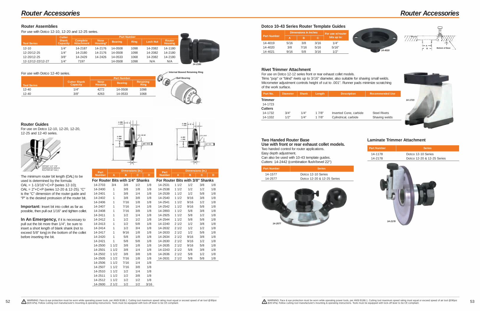
Internal Bowed Retaining Ring
Ball Bearing
Router Accessories
53
Router Accessories
52 WARNING: Face & eye protection must be worn while operating power tools, per ANSI B186.1. Cutting tool maximum speed rating must equal or exceed speed of air tool @ 90psi(620 kPa). Follow cutting tool manufacturer’s mounting & operating instructions. Tools must be equipped with lock-off lever to be CE compliant.
WARNING: Face & eye protection must be worn while operating power tools, per ANSI B186.1. Cutting tool maximum speed rating must equal or exceed speed of air tool @ 90psi(620 kPa). Follow cutting tool manufacturer’s mounting & operating instructions. Tools must be equipped with lock-off lever to be CE compliant.
Router AssembliesFor use with Dotco 12-10, 12-20 and 12-25 series.
Cutter Part NumberShank Complete Nose Bearing Ring Lock Nut Router
Tool Series Capacity Attachment Housing* Housing
12-10 1/4” 14-2187 14-2176 14-0508 1098 14-2082 14-118012-20/12-25 1/4” 14-2180 14-2176 14-0508 1098 14-2082 14-218012-20/12-25 3/8” 14-2429 14-2426 14-0533 1068 14-2082 14-218012-12/12-22/12-27 1/4” 7197 14-0508 1098 N/A N/A
For Router Bits with 1/4” Shanks14-2703 3/4 3/8 1/2 1/814-2400 1 3/8 1/8 1/814-2401 1 3/8 1/4 1/814-2402 1 3/8 3/8 1/814-2406 1 7/16 1/8 1/814-2407 1 7/16 1/4 1/814-2408 1 7/16 3/8 1/814-2411 1 1/2 1/4 1/814-2412 1 1/2 1/2 1/814-2413 1 1/2 5/8 1/814-2414 1 1/2 3/4 1/814-2417 1 9/16 1/8 1/814-2420 1 5/8 1/8 1/814-2421 1 5/8 5/8 1/814-2500 1 1/2 3/8 1/8 1/814-2501 1 1/2 3/8 1/4 1/814-2502 1 1/2 3/8 3/8 1/814-2505 1 1/2 7/16 1/8 1/814-2506 1 1/2 7/16 1/4 1/814-2507 1 1/2 7/16 3/8 1/814-2510 1 1/2 1/2 1/4 1/814-2511 1 1/2 1/2 3/8 1/814-2512 1 1/2 1/2 1/2 1/814-2600 2 1/2 1/2 1/2 3/16
Part Dimensions (in.)
Number A B C D
Router GuidesFor use on Dotco 12-10, 12-20, 12-20, 12-25 and 12-40 series.
The minimum router bit length (OAL) to beused is determined by the formula:OAL = 1-13/16”+C+P (series 12-10);OAL = 2”+C+P (series 12-20 & 12-25). “C”is the “C” dimension of the router guide and“P” is the desired protrusion of the router bit.
Important: Insert bit into collet as far aspossible, then pull out 1/16” and tighten collet.
In An Emergency, if it is necessary topull out the bit more than 1/4”, be sure toinsert a short length of blank shank (not toexceed 5/8” long) in the bottom of the colletbefore inserting the bit.
Part Dimensions (in.)
Number A B C D
For Router Bits with 3/8” Shanks14-2531 1 1/2 1/2 3/8 1/814-2538 1 1/2 1/2 1/2 1/814-2539 1 1/2 1/2 5/8 1/814-2540 1 1/2 9/16 3/8 1/814-2541 1 1/2 9/16 1/2 1/814-2542 1 1/2 9/16 5/8 1/814-2893 1 1/2 5/8 3/8 1/814-2925 1 1/2 5/8 1/2 1/814-2544 1 1/2 5/8 5/8 1/814-2240 2 1/2 1/2 3/8 1/814-2632 2 1/2 1/2 1/2 1/814-2633 2 1/2 1/2 5/8 1/814-2634 2 1/2 9/16 3/8 1/814-2630 2 1/2 9/16 1/2 1/814-2635 2 1/2 9/16 5/8 1/814-2243 2 1/2 5/8 3/8 1/814-2636 2 1/2 5/8 1/2 1/814-2631 2 1/2 5/8 5/8 1/8
14-2180
For use with Dotco 12-40 series.Part Number
Cutter Shank Nose Bearing RetainingTool Series Capacity Housing RIng
12-40 1/4” 4272 14-0508 109812-40 3/8” 4263 14-0533 1068
5/8-18NF
.390” DIA
OFFSET 1/2” (“B”DIMENSION MINUSROUTER BIT DIA.)
14-4019 5/16 3/8 3/16 1/4”14-4020 3/8 7/16 5/16 5/16”14-4021 9/16 5/8 3/16 1/2”
Dimensions in Inches For use w/routerPart Number
A B C bits up to:
14-4020
Part No. Diameter Shank Length Description Recommended Use
14-1577 Dotco 12-10 Series14-2577 Dotco 12-20 & 12-25 Series
Two Handed Router BaseUse with front or rear exhaust collet models.Two handed control for router applications.Easy depth adjustment.Can also be used with 10-43 template guides.Cutters: 14-2442 (combination flush/bevel 22°)
Part Number Series
Rivet Trimmer AttachmentFor use on Dotco 12-12 series front or rear exhaust collet models.Trims “pop” or “blind” rivets up to 3/16” diameter, also suitable for shaving small welds.Micrometer adjustment controls height of cut to .001”. Runner pads minimize scratchingof the work surface.
Dotco 10-43 Series Router Template Guides
Trimmer14-1723
Cutters14-1732 3/4” 1/4” 1 7/8” Inverted Cone, carbide Steel Rivets14-1332 1/2” 1/4” 1 7/8” Cylindrical, carbide Shaving welds
14-1178 Dotco 12-10 Series14-2178 Dotco 12-20 & 12-25 Series
Laminate Trimmer Attachment
Part Number Series
14-1723
14-257714-2178
Bottom of BaseB
C
A

5554 WARNING: Face & eye protection must be worn while operating power tools, per ANSI B186.1. Cutting tool maximum speed rating must equal or exceed speed of air tool @ 90psi(620 kPa). Follow cutting tool manufacturer’s mounting & operating instructions. Tools must be equipped with lock-off lever to be CE compliant.
WARNING: Face & eye protection must be worn while operating power tools, per ANSI B186.1. Cutting tool maximum speed rating must equal or exceed speed of air tool @ 90psi(620 kPa). Follow cutting tool manufacturer’s mounting & operating instructions. Tools must be equipped with lock-off lever to be CE compliant.
Saws Saws
9,000 – 34,000 RPM
0.3 – 1.7 hp (0.22 – 1.27 kW)
*NOTE: Maximum depth of cut is based on maximum saw blade capacity.
GENERAL:Minimum Hose I.D.– 12-12 Series: 1/4” (6.4mm)
12-20,12-22, 12-25, 12-27 Series: 5/16” (7.9mm)12-42 Series: 1/2” (12.7mm)
All tools performance rated @ 90psi (620 kPa) air pressure.
STANDARD EQUIPMENT:Applicable wrenches, oilless blades (•)12-27 & 12-42 Series: 3/4” Arbor adapter.
EXTRA EQUIPMENT:Overhose (rear exhaust): See page 63Blades: See pg. 56
Vacuum conversion kits for standard models see pg. 57Arbor Adapters (12-7 Models): Order 14-2596 and 14-2597 to adapt to3/4” arbor hole saw blades.
OPTIONAL EQUIPMENT:12-27 & 12-42 Arbor adapters: May be substituted on request:
1/2” arbor hole – 2 spacers (14-2575)5/8” arbor hole – bushing (14-2574)7/8” arbor hole – bushing (14-2576)1” arbor hole – bushing (14-2572)
Refer to Page 7 for description of Rapid Select.
12-20 Series – 0.6 hp (0.45 kW) – Oscillating – Inline12L2065-90• 14,000 9/16” 2 1/2” 2.1 1.0 8.9 226 1/4”
12-22 Series – 0.6 hp (0.45 kW) – Oscillating – Right Angle12L2240-90• 14,000 9/16” 2 1/2” 2.3 1.0 10.9 277 1/4”
12-12 Series - 0.3 hp (0.22 kW)12S1283-02 20,000 2” 7/16” 1.3 0.6 7.1 180 1/4”12S1282-02 12,000 2” 7/16” 1.3 0.6 7.1 180 1/4”12S1288-02 2,400 2” 7/16” 1.6 0.7 8.9 226 1/4”12S1274-03 (Vac Ready) 20,000 2” 7/16” 2.3 1.0 7.1 180 1/4”12S1273-03 (Vac Ready) 12,000 2” 7/16” 2.3 1.0 7.1 180 1/4”
12-27 Series - 0.9 hp (0.67 kW)12S2794-01 (Vac Ready) 4,700 2 1/2” 9/16” 4.6 2.1 13.2 335 1/4”12S2792-01 (Vac Ready) 940 2 1/2” 9/16” 5.6 2.5 15.0 381 1/4”12S2794-02 (Vac Ready) 4,700 4” 1” 5.2 2.4 14.5 368 1/4”12S2792-02 (Vac Ready) 940 4” 1” 6.2 2.8 16.2 411 1/4”
12S2749-01 11,000 4” 1” 4.8 2.2 11.4 290 1/4”12S2774-02 (Floor bag) 7,000 4” 1” 6.5 2.9 14.1 358 1/4”
12-42 Series - 1.7 hp (1.27 kW)12S4218-01• 8,600 4” 1” 7.9 3.6 15.5 394 1/2”12S4216-01• 5,800 4” 1” 7.9 3.6 15.5 394 1/2”
12S4225-03• (Vac Adapt) 8,500 4” 1” 9.2 4.2 17.0 432 1/2”12S4225-02 (Floor bag) 8,500 4” 1” 9.2 4.2 17.0 432 1/2”
Free Saw Maximum AirModel Number Speed Blade Depth Weight Length Inlet
Front Exhaust Side Exhaust Rear Exhaust Vacuum rpm Capacity of Cut* lbs. kgs in. mm Size
12-12
12-27
12-42
GENERAL:Air Inlet: 1/4" NPTFMinimum Hose Size: 1/4"Tool performance rated at 90 psi (620kPa) air pressure.STANDARD EQUIPMENT:Operating instructions and service manual18 teeth/in. blade: 204271
OPTIONAL EQUIPMENT:24 teeth/in. blade: 204272
Refer to Page 7 for description of Rapid Select.
Cutting Capacity Blade Capacity Length Height Width Weight
Model in. mm in. mm in. mm in. mm in. mm lbs. kg
136 Series Band Saw – .75 hp (.56 kW)136BSV-4 4.8 122 44 7/8 x 1/2 x .02 1140 x 12.7 x .5 22.25 565 7.0 178 8.3 211 12.5 5.7
136 Series Band Saw
m Variable Speed Control
m Adjustable Handle
m Lock-off Lever Start136BS
New! Ergonomic Safety LeverBeginning July 2004, all Dotco“S” tools will be shipped with ournew comfort grip safety lever.
12-22

5756 WARNING: Face & eye protection must be worn while operating power tools, per ANSI B186.1. Cutting tool maximum speed rating must equal or exceed speed of air tool @ 90psi(620 kPa). Follow cutting tool manufacturer’s mounting & operating instructions. Tools must be equipped with lock-off lever to be CE compliant.
WARNING: Face & eye protection must be worn while operating power tools, per ANSI B186.1. Cutting tool maximum speed rating must equal or exceed speed of air tool @ 90psi(620 kPa). Follow cutting tool manufacturer’s mounting & operating instructions. Tools must be equipped with lock-off lever to be CE compliant.
Saw Accessories
Saw Blades – 1/4” arbor hole14-1875 1 1/4” High Speed Steel 22 Teeth 3/32” x 1/16” 12,000 Aluminum, Laminated Plastics, Pressed Board, Wood14-0930 1 1/4” High Speed Steel 44 Teeth 3/32” x 1/16” 12,000 Aluminum, Laminated Plastics, Pressed Board, Wood14-1895 1 1/2” High Speed Steel 22 Teeth 7/32” x 1/16” 12,000 Aluminum, Laminated Plastics, Pressed Board, Wood14-1890 2” High Speed Steel 22 Teeth 7/16” x 1/16” 12,000 Aluminum, Laminated Plastics, Pressed Board, Wood14-1891 2” High Speed Steel 44 Teeth 7/16” x 1/16” 12,000 Aluminum, Laminated Plastics, Pressed Board, Wood14-1892 2” High Speed Steel 60 Teeth 7/16” x 1/16” 12,000 Aluminum, Laminated Plastics, Pressed Board, Wood14-1396* 1 1/2” Carbide Chip 36/80 Grit 7/32” x 3/32” 20,000 Fiberglass, Rubber14-1395* 2” Carbide Chip 36/80 Grit 7/16” x 3/32” 20,000 Fiberglass, Rubber14-1398* 1 1/2” Diamond Chip 40/60 Grit 7/32” x 5/64” 20,000 Fiberglass, Rubber14-1400* 2” Diamond Chip 40/60 Grit 7/16” x 5/64” 20,000 Fiberglass, Rubber
*CAUTION: Use only for sawing non-metallic materials.
Diameter Type Maximum Depth Maximum Recommended UsePart Number & Width of Cut rpm (Guidelines only)
Saw Blades – 7/16” arbor hole14-2147 2 1/2” High Speed Steel 44 Teeth 9/16” 12S2794-01 1/4” Aluminum, 1/2” Plywood, 1/2” Phenolic14-2146 2 1/2” High Speed Steel 80 Teeth 9/16” 12S2793-01 16 Gauge Steel14-2928 3 3/8” High Speed Steel 60 Teeth 15/16” 12S2794-02 1/4” Aluminum, 1/2” Plywood, 1/2” Phenolic14-2929 3 3/8” High Speed Steel 80 Teeth 15/16” 12S2792-02 20 Gauge Steel, Paneling, Plywood14-1887 2” High Speed Steel 22 Teeth 7/16” x 1/16” 12S1288-04 Aluminum, Laminated Plastics, Pressed Board, Wood14-1888 2” High Speed Steel 44 Teeth 7/16” x 1/16” 12S1288-04 Aluminum, Laminated Plastics, Pressed Board, Wood14-1889 2” High Speed Steel 60 Teeth 7/16” x 1/16” 12S1288-04 Aluminum, Laminated Plastics, Pressed Board, Wood
Diameter Type Maximum Use With Recommended Use Up ToPart Number Depth of Cut Model (Guidelines only)
Saw Blades – 3/4” arbor hole14-2701* 4” Carbide Chip 36/80 Grit** 1” x 1/8” Fiberglass, Hard Rubber14-2694* 4” Carbide Chip 36 Grit 1” x 11/64” Hard Rubber14-2697* 4” Carbide Chip 80 Grit 1” x 1/8” Fiberglass14-2699* 4” Carbide Tip 20 Teeth 1” x 7/64” Thin Fiberglass, Plastic Laminates to 1/8” thick14-2700* 4” Carbide Tip 20 Teeth 1” x 7/64” Thicker Fiberglass, Plastic Laminates to 1/2” thick14-2710 4” Carbide Tip 20 Teeth 1” x 7/64” Thin non-ferrous material (to approx. 1/8” thick)14-2711 4” Carbide Tip 12 Teeth 1” x 7/64” Thicker non-ferrous material (to approx. 1/2” thick)14-2690* 4” Diamond Chip 60/80 Grit 1” x 5/64” Fiberglass
*CAUTION: These carbide chip and tip and diamond blades are not to be used on metallic materials.**Slim blade for easy cutting of fiberglass, with minimum dust -36 grit on periphery and 80 grit on the sides.
Diameter Type Maximum Depth Recommended UsePart Number & Width of Cut (Guidelines only)
14-1891 14-2928 14-2700
Saw Accessories
Saw Blades – Dotco oscillating saws with 3/8” arbor hole14-1740* 2” Carbide Chip 36/80 Grit 7/16” x 3/32” Fiberglass14-1741* 2” Diamond Chip 40/60 Grit 7/16” x 5/64” Fiberglass, Carbon Composites14-1742 2 1/2” Stainless Steel 124 Teeth 9/16” x 3/64” Wood, Uncured or Cured Composites, Aluminum, Plastic14-1746 2 1/2” Flush Stainless 124 Teeth 9/16” x 3/64” Wood, Uncured or Cured Composites, Aluminum, Plastic14-1743 2 1/2” Carbide 120 Teeth 9/16” x 1/16” Cured Graphic Composites14-1744 2 1/2” Razor 9/16” x 3/64” Cardboard, Light Plastic14-1745 2 1/2” Stainless Steel 120 Teeth 9/16” x 3/64” Confined Space14-1747 3” Razor 9/16” x 3/64” Cardboard, Light Plastic
*Use only for sawing non-metallic materials.
Diameter Type Maximum Depth Recommended UsePart Number & Width of Cut (Guidelines only)
Vacuum Conversion KitsDotco 12-27 seriesTo convert an existing Dotco front exhaust series 12-27 saw toVacuum operation, order any of the conversion kits listed in thetable. Refer to the Vacuum Ready models listed on page 101 asa guideline to selection. NOTE: When converting to vacuum, freespeed of the tool will be reduced 20%.
Part Number Converts front exhaust to this configuration
2704 Option 1 – Porta Bag2705 Option 2 – Floor Bag2729 Option 3 – Vacuum System Adapter
Dotco 12-42 seriesTo convert an existing Dotco front exhaust series 12-42 saw toVacuum operation, order any of the conversion kits listed in thetable. Refer to the Vacuum Ready models listed on page 102 asa guideline to selection. NOTE: When converting to vacuum, freespeed of the tool will be reduced 20%.
4131 Option 1 – Porta Bag4132 Option 2 – Floor Bag4133 Option 3 – Vacuum System Adapter
Part Number Converts front exhaust to this configuration
14-1742

*Less chisel
GENERAL:Air Inlet: 3/8” NPT. Minimum Hose Size: 1/2” (12.7mm)Air Consumption CH-30: 31.5 cfm: CH4: 28.2 cfmTool performance rated at 90 psi (620kPa) air pressure.
STANDARD EQUIPMENT: Operating instructions & service manual
Refer to Page 7 for description of Rapid Select.
5958 WARNING: Face & eye protection must be worn while operating power tools, per ANSI B186.1. Cutting tool maximum speed rating must equal or exceed speed of air tool @ 90psi(620 kPa). Follow cutting tool manufacturer’s mounting & operating instructions. Tools must be equipped with lock-off lever to be CE compliant.
WARNING: Face & eye protection must be worn while operating power tools, per ANSI B186.1. Cutting tool maximum speed rating must equal or exceed speed of air tool @ 90psi(620 kPa). Follow cutting tool manufacturer’s mounting & operating instructions. Tools must be equipped with lock-off lever to be CE compliant.
Percussion Tools
SC Series Triple Scalerm Piston Type
SC3A Series Triple ScalerSC 3A 0.88 22 0.81 21 5200 13.3 338 7.9 3.6
GENERAL:Air Inlet: 3/8” NPTMinimum Hose Size: 3/8”Tool performance rated at 90 psi (620kPa) air pressure.
STANDARD:Operating instructions & service manual
Model NumberBore Stroke Blows Per Length Weight
in. mm in. mm Minute in. mm in. mm
SC-3A
F Series Riveters – Round Taper Nose – Pistol GripF2-PT-RT-B 0.56 14 2.0 52 3900 .401 10.2 6.7 170 2.7 1.2F4-PT-RT-B 0.56 14 4.0 102 1700 .401 10.2 8.7 222 3.3 1.5
F Series Rivetersm For driving 1/8”-1/4” (3-6mm) rivetsm Standard beehive retainerm Built-in air regulator controls power outputm Spool valve for precise speed control
GENERAL:Air Inlet: 1/4” NPTF; Minimum Hose Size: 1/4”Tool performance rated at 90 psi (620kPa) air pressure.
STANDARD EQUIPMENT:Operating instructions & service manual
Refer to Page 7 for description of Rapid Select.
For Use With RivetModel Number Bore Stroke Blows Per Set Shank Dia. Length Weight
Bee Hive Retainer in. mm in. mm Minute in. mm in. mm lbs. kg
Model Number Retainer Bore Stroke Blows Per Length* Weight*
Round Nose Hex Nose Type in. mm in. mm Minute in. mm lbs. kg
CH-30 Series Chipping Hammers – Pistol Grip HandleCH-30-RD CH-30-HX Standard 1 1/8 28.5 2 1/2 64 2200 17.7 450 15.0 6.8CH-30-RD-QC CH-30-HX-QC Quick Change 1 1/8 28.5 2 1/2 64 2200 17.7 450 15.0 6.8
CH4 Series Chipping Hammers – 4 Bolt Spade HandleCH4-30-RD Standard 1 1/8 28.5 2 1/2 64 2000 15.7 398 18.4 8.4CH4-30-RD-QC Quick Change 1 1/8 28.5 2 1/2 64 2000 15.7 398 18.4 8.4
CH-30-RD
CH4-30-RD
F2-PT-RT F4-PT-RT
CH-30, CH4 Series Chipping Hammersm Heavy duty for rugged usem Ring valve hard hitting hammerm Forged steel hammerm Heat treated cylinder & piston for reduced wearm Replaceable bushing
Percussion Tools
Model Number Bore Stroke Blows Per Length* Weight*
Round NoseType
in. mm in. mm Minute in. mm lbs. kg
B1 Series Needle Scalers – Lever StartB1-CNB-LT-RD Needle 1.0 25 1.1 28 4600 15.0 381 6.3 2.9
B1 Series Needle Scalers – Lever Start Kit**B1-CNB-LT-RD-K Needle 1.0 25 1.1 28 4600 15.0 381 6.3 2.9
* Length and weight include needles.**Specs are for tool only
GENERAL:Air Inlet: 1/4” NPTFMinimum Hose Size: 5/16”Tool performance rated at 90 psi (620kPa) air pressure.Note: Kit includes tool, whip hose, extra set of needles, two
chisels, extra chisel retainer, retainer parts and metal case.
STANDARD EQUIPMENT: Operating instructions & service manual
OPTIONAL EQUIPMENT: Additional Accessories: Page 62
Refer to page 7 for description of Rapid Select.
Bore Stroke Blows Per Length* Weight*
Model NumberType
in. mm in. mm Minute in. mm lbs. kg
B1 Series Chisel Scaler – Push-Pull StartB1-C-PT Chisel 1.0 25 1.1 28 4600 12.0 305 4.3 2.0
B1 & BR Series Chisel Scalers – Lever StartB1-C-LT Chisel 1.0 25 1.1 28 4600 10.3 262 4.3 2.0BR-C-LT Chisel 1.0 25 1.1 28 4200 10.4 264 4.3 2.0
*Length and weight does not include chisel
GENERAL:Air Inlet: 1/4” NPTFMinimum Hose Size: 5/16”Tool performance rated at 90 psi (620kPa) air pressure.
STANDARD EQUIPMENT: Operating instructions & service manual
OPTIONAL EQUIPMENT: Additional Accessories: Page 62
Refer to page 7 for description of Rapid Select.
B1-CNB-LT-RD-K
B1-CNB-LT-RD
B1, BR Series Needle Scalersm Built-in Chisel Retainer
m Front Exhaust
m Lever Start
m Needle Type
B1, BR Series Chisel Scalersm Built-in Chisel Retainer
m Lever & Push-Pull Start Models
m Chisel Type
BR-C-LT
B1-C-PT

6160 WARNING: Face & eye protection must be worn while operating power tools, per ANSI B186.1. Cutting tool maximum speed rating must equal or exceed speed of air tool @ 90psi(620 kPa). Follow cutting tool manufacturer’s mounting & operating instructions. Tools must be equipped with lock-off lever to be CE compliant.
WARNING: Face & eye protection must be worn while operating power tools, per ANSI B186.1. Cutting tool maximum speed rating must equal or exceed speed of air tool @ 90psi(620 kPa). Follow cutting tool manufacturer’s mounting & operating instructions. Tools must be equipped with lock-off lever to be CE compliant.
Specialty ToolsSpecialty Tools
Rivet Shavers
m Non-Reversible
FreeModel Number Cutter Speed Weight Length
Small Handle Large Handle Adjustment rpm lbs. kgs in. mm
*For weight and length of large handle models, add 0.20 lb.(0.1kg)GENERAL:Air Inlet: 1/4” NPT - Use 5/16” (7.9mm) I.D. HoseAll tools performance rated @ 90psi (620 kPa) air pressure
STANDARD EQUIPMENT: Stabilizer and choice of skirt
EXTRA EQUIPMENT: Carbide Cutters & Extended Skirts: See table
14CF Series – Pistol Grip – 0.4 hp (0.30 kW) – with Stabilizer14CFS60-95 0.0005 29,000 2.3 1.0 8.2 210
14CF Series – Pistol Grip – 0.4 hp (0.30 kW) – without Stabilizer14CFS60-98 0.00025 29,000 2.3 1.0 8.2 210
14CN Series – Pistol Grip – 0.9 hp (0.67 kW) – with Stabilizer14CNL60-95 0.0005 20,000 4.5* 2.0* 8.9* 226*
0.00025 20,000 4.5* 2.0* 8.9* 226*
Cutter Part Number
Diameter Carbide Skirts 1” Extended Skirt 4” Extended Skirt 6” Extended Skirtin. Cutter Std. Wide Adapter Skirt Assembly Adapter Skirt Assembly Adapter Skirt Assembly
5/16 – 14-4391 14-4401 – – – – – – – – –3/8 14-4382 14-4392 14-4402 – – 14-4532 14-4302 14-4312 14-4512 – 14-4372 14-45727/16 14-4383 14-4393 14-4403 14-4323 – 14-4533 14-4303 – 14-4513 14-4363 14-4373 14-45731/2 14-4384 14-4394 14-4404 14-4324 14-4334 14-4534 – – 14-4514 14-4364 14-4374 14-45749/16 14-4385 14-4395 14-4405 – – – – – – – – –5/8 14-4386 14-4396 14-4406 – – – 14-4306 14-4316 14-4516 – – –3/4 14-4387 14-4397 – – – – – – – – – –1 14-4422 14-4410 – – – – – – – – – –
1-1/4 – 14-4412 – – – – – – – – – –
14CN
14CF
Lint Pickers
m Front or Rear Exhaust
Free Model Number Speed Weight* Length Collet
Front Exhaust Rear Exhaust rpm ozs. gr in. mm Size
12-10 Series – 0.3 hp (0.22 kW) – 300 Series Collet12L1010-36 20,000 12 269 4.8 122 1/4”
12L1031-36• 20,000 13 340 5.5 140 1/4”
Nibblers
REPLACEMENT PARTS ANDACCESSORIESExtra Cost: 14-1752: Punch
14-1751: Die
EXTRA EQUIPMENT:For lock-off safety lever, substitute “S” for“L” in model number.Overhose: See page 63
Model Number Capacity – Gauge Speed Weight Length
Rear Exhaust Mild Steel SS spm lbs. kgs in. mm
12-20F Series – 0.6hp (0.45 kW)12L2062-96 18 – 6 1.1 0.5 8.3 211
12-20
Shears & Scissors
*Non-ferrous metals, plastics, fiberglass, etc.
GENERAL:Air Inlet: 1/4” NPT – Use 5/16” (7.9mm) I.D.HoseAll tools performance rated @ 90psi (620 kPa) air pressure
STANDARD EQUIPMENT:Shear attachment and cutter blades
EXTRA EQUIPMENT:Overhose: See page 63Replacement cutter blades for 14-1550Standard Sheer Right: 14-1554
Left: 14-1553Center: 14-1555
Replacement cutter blades for 14-1650Scissor Shear Blade: 14-1651
Side Knife: 14-1652
Attachment CapacityModel Number Standard Scissor Mild Steel Other Weight LengthRear Exhaust Shear Shear Gauge Materials* lbs. kgs in. mm
14CF Series – 0.4 hp (0.30 kW)14CFS93-99 14-1550 18 1/16* 2.2 1.0 8.0 20014CFS93-98 14-1650 18 1/16* 2.4 1.1 9.8 250
14CFS93-98
GENERAL:Air Inlet: Front Exhaust:1/4” NPT
Rear Exhaust: 1/8” NPT – Use 1/4” (6.4mm) I.D. Hose
All tools performance rated @ 90psi (620 kPa) air pressure
STANDARD EQUIPMENT:Applicable collet, collet wrenches, 6”(152mm) Picker Rod 14-2181,
oilless blades(•)
EXTRA EQUIPMENT:For lock-off safety lever, substitute “S” for“L” in model number.Collets: See page 26Overhose (rear exhaust): See page 639” (229mm) Picker Rod 14-2182
Refer to Page 7 for description ofRapid Select.
12L1010-36
Hole Grinders
m High-speed drilling/grinding hardened alloys
m Fine cutting of thin walls sections
m Materials too fragile for conventional methods
m Use on lathes, grinders, mills or drill pressesfor straightline machining
m Insert in a boring head for offset jig grinding
m Mount permanently for special applications
GENERAL:Air Inlet: 1/4” NPT – Use 5/16” (7.9mm) I.D. HoseAir Consumption: 11-10 Series – 12 cfm (0.34 m3/min)
11-20 Series – 20 cfm (0.57 m3/min)All tools performance rated @ 90psi (620 kPa) air pressure
STANDARD EQUIPMENT:11-10 series: 1/4” (308) collet, collet wrenches, push-pull valve, coupling, and nipple11-20 series: 1/4” (208) collet, collet wrenches, push-pull valve, coupling, and nipple
Shank Collet Speed Weight Approximate Dimensions (inches)Model Number Dia. Chuck rpm lbs. kgs ”A” ”B” ”C” ”D” ”E” ”F” ”G” ”H”
11-20 Series – 0.6 hp (0.45 kW)11Q2000 1/2” 200 25,000 3 1.4 1.3 6.3 1.3 0.8 0.8 1.0 0.8 –
11Q2000
A
B
C
DEF
G
H
©
©
© ©
©
©
©
©
©
©
©
©
©
©
©
©
ShankSizes
©

6362 WARNING: Face & eye protection must be worn while operating power tools, per ANSI B186.1. Cutting tool maximum speed rating must equal or exceed speed of air tool @ 90psi(620 kPa). Follow cutting tool manufacturer’s mounting & operating instructions. Tools must be equipped with lock-off lever to be CE compliant.
WARNING: Face & eye protection must be worn while operating power tools, per ANSI B186.1. Cutting tool maximum speed rating must equal or exceed speed of air tool @ 90psi(620 kPa). Follow cutting tool manufacturer’s mounting & operating instructions. Tools must be equipped with lock-off lever to be CE compliant.
Percussion Tool Accessories
Type Cutting Edge Round Stock Size Overall Length Codein. mm in. mm in. mm Number
Blank — – 5/8 16 7 1/2 190 829173Long Wide Blade 1 3/4 x 3/32 44.5 x 2.4 5/8 16 7 203 829165Cold 3/4 x 3/32 19.1 x 2.4 5/8 16 8 1/2 216 829150Scaling 1 1/4 x 3/32 31.8 x 2.4 5/8 16 9 229 829301Spoon 1 3/8 x 3/32 34.9 x 2.4 5/8 16 7 1/2 190 829310
BR Series Chisels (Safety Retainer Type)
Type Cutting Edge Square Stock Size Overall Length Codein. mm in. mm in. mm Number
Hardened Blank — — 1/2 12.7 7 1/2 190 839052Hardened Blank — — 1/2 12.7 12 305 839053Cold Chisel 3/4 19 1/2 12.7 7 1/2 190 839051Cold Chisel 3/4 19 1/2 12.7 12 305 839341Cold Chisel 3/4 19 1/2 12.7 18 457 839335Cold Chisel 1 1/2 38 1/2 12.7 8 203 839467Spoon Chisel 1 3/8 35 1/2 12.7 7 1/4 184 839050Spoon Chisel 1 3/8 35 1/2 12.7 12 305 839299Spoon Chisel 1 3/8 35 1/2 12.7 18 457 839334Spoon Chisel 1 25 1/2 12.7 7 1/4 184 839740
B1 Series Chisels (Safety Retainer Type)
839053839341
829173
829168
829310
Overhose AssembliesFor use with Dotco series rear exhaust tools:
Rear exhaust tool
Air intake hoseAir exhaust Exhaust
overhose
Overhose Non-Overhose Overhose Only Airhose OnlyTool Series and to Overhose
NumberLength
NumberLength
Airhose Conversion Kit ft. m ft. m
10-04 45-0946 45-0945 1.0 0.3 45-0948 5.0 1.545-0953 45-0955 2.0 0.6 45-0948 5.0 1.545-0954 45-0956 4.0 1.2 45-0948 5.0 1.5
12-03, 12-04 45-6013 45-6003 1.0 0.3 45-0948 5.0 1.545-6012 45-6002 2.0 0.6 45-0948 5.0 1.545-6000 45-6001 4.0 1.2 45-0948 5.0 1.5
10-10, 10-11, 10-12 45-1930 45-1904 2.0 0.6 45-1409 8.0 2.445-1931 45-1901 4.0 1.2 45-1409 8.0 2.445-1932 45-1902 8.0 2.4 45-1409 8.0 2.4
12-10, 12-11, 12-12 45-2783 45-2629 2.0 0.6 45-1408 8.0 2.412-13, 15LF, 15-14 45-2784 45-2687 4.0 1.2 45-1408 8.0 2.4
45-2785 45-2688 8.0 2.4 45-1408 8.0 2.4
10-20, 10-21, 10-22 45-2786 45-2629 2.0 0.6 45-1508 8.0 2.410-25, 10-26, 10-27 45-2787 45-2687 4.0 1.2 45-1508 8.0 2.412-20, 12-21, 12-22 45-2788 45-2688 8.0 2.4 45-1508 8.0 2.412-25, 12-26, 12-27, 12-28, 15LS, 15lN
12-91 45-0974 4.0 1.2 01-9167 5.0 1.5
14CF 45-2687 4.0 1.2 45-1508 8.0 2.4
14CS 45-2687 2.0 0.6 45-1408 8.0 2.445-2687 4.0 1.2 45-1408 8.0 2.445-2688 8.0 2.4 45-1408 8.0 2.445-2688 8.0 2.4 45-1408 8.0 2.4
14CN 45-2687 2.0 0.6 45-1508 8.0 2.445-2687 4.0 1.2 45-1508 8.0 2.4
1025687 45-2688 8.0 2.4 45-1508 8.0 2.445-2688 8.0 2.4 45-1508 8.0 2.4
General Accessories

General Accessories
65
General Accessories
64
10-04 75 - 7810-41 77 - 8210-43 8310-56 8410-58 8610-90 7510-95 7411-43 8312-03 7812-04 7812-05 8012-10 78-8312-11 8612-12 77-8412-13 78-8312-18 7812-20 77-8512-21 77-8512-22 8312-23 8412-25 75-8412-26 76-8212-27 76-85
12-28 75-8512-31 79-8412-40 8312-41 77-8212-42 7912-51 7812-53 7812-91 6814CF 7715-14 7715-20 7815-29 7815CN 8015CN (Euro) 7415CS 7815CS (Euro) 7215LF 7815LN 8215LS 8056CN 8456CS 8256CT 7815Z 66-67
Average dBA Reading of Tools at Free Speed
Dotco Series Tools dBA* Dotco Series Tools dBA*
Coupler (male NPT)1/8 45-0710 – –1/4 45-0711 45-0713 –3/8 45-0712 – –1/2 – – 45-0717
Coupler (female NPT)1/4 – – –3/8 45-0732 45-0734 45-0736
Nipple (male NPT)1/8 45-0720 – –1/4 – 45-0724 –3/8 45-0722 45-0725 45-07261/2 – – 45-0727
Nipple (female NPT)1/4 – 45-0744 –3/8 45-0742 45-0745 45-07461/2 – – 45-0747
Nipple (with hose barbs)1/4** 45-0748 – –1/2** – – 45-0753
Fitting Type* NPT Nominal Size
in. 1/4” 3/8” 1/2”
Air Pressure Gage Kit
Part Number Description
A13157 Gage, needle, cap & case
Quick Disconnect Fittings
Part No. NPT Air Flow Max. Pressure Weight
in. SCFM m3/min psig bar lbs. kg
SW-102 1/4 25 7.1 150 10.4 0.20 0.09SW-103 3/8 45 12.7 150 10.4 0.40 0.18SW-104 1/2 65 18.4 150 10.4 0.80 0.36SWR-102* 1/4 25 7.1 150 10.4 0.25 0.11
* NOTE: Equipped with built-in flow regulator..
Activeswivel
* NOTE: Nipples of one size will not fit couplers of another size.** NOTE: Indicates inside diameter of hose.NOTE: 1/4” nominal will pass 49 cfm free air @ 90 psi, but pressure drop
exceeds 10 psi with air flow over 30 cfm.3/8” nominal will pass 90 cfm free air @ 90 psi, but pressure drop exceeds 10 psi
with air flow over 53 cfm.1/2” nominal will pass 168 cfm free air @ 90 psi, but pressure drop exceeds 10
psi with air flow over 109 cfm.
Steel Handle Bushings
Part Number Size
881276 *1/4 in. MPT x 1/4 in. FPT841554 †1/4 in. MPT x 1/4 in. FPT841553 3/8 in. MPT x 1/4 in. FPT841552 3/8 in. MPT x 3/8 in. FPT
* Light duty for rotary tools† Heavy duty for percussion tools.
Swivel Hose Couplings
Part Number NPT in.
A20744 1/4A20741 3/8A20764 1/2
Part DescriptionNPT Air Flow Max. Pressure
Number in. SCFM m3/min psig bar
45-0211 Filter w/cartridge* 1/4 17 8.0 100 6.945-0212 Filter cartridge – – – – –45-0201 Lubricator** 1/4 22 10 100 6.945-0301 Lubricator** 3/8 22 10 100 6.9
GENERAL: Use where inconvenient for standard filter or lubricator.* NOTE: Filter will not remove water.** NOTE: One ounce reservoir good for an average eight hour shift.
Airline Filter and Lubricator
Part Hose I.D. Fittings (NPT) LengthNumber in. mm in. mm ft. m
A110026 3/16 4.7 1/8 3/8-24* 6.0 1.8A139856 3/16 4.7 1/8 1/8 6.0 1.845-1307 3/16 4.7 1/8 1/4 7.0 2.145-1408 1/4 6.4 1/4 1/4 8.0 2.445-1409 1/4 6.4 1/8 1/4 8.0 2.445-1508 5/16 7.9 1/4 1/4 8.0 2.445-1610 3/8 9,5 3/8 3/8 10 3.045-1810 1/2 12.7 3/8 1/2 10 3.045-1812 1/2 12.7 1/2 1/2 12 3.745-1825 1/2 12.7 1/2 1/2 25 7.6
GENERAL: 3/16” & 1/4” hoses have braided covers, all others have neoprene covers.
* NOTE: 3/8”-24 is a straight thread
Air Hoses
Lubricants
Push Type Grease GunPart Number: 45-1982
Service Tools
“T” Wrenches1021202 3/16” Hex socket screws
To remove and replace hex socket screws in tool housings.
Hex Key Wrenches1008860 1/8”1006443 3/16”
Torx Torque Adjustment Keys535508 H16/H30 series tools
Part Number Size Description M.S.D.S. No.
Oils540397 1 qt. plastic Air line oil CPT-153533485 1 gal. metal Air line oil CPT-153536333 1 gal. metal High film strength CPT-15445-0918 1 qt. plastic Air line oil (Dotco) CPT-15545-0919 1 gal metal Air line oil (Dotco) CPT-155539317 1 qt. plastic Hydraulic oil (Pulse) CPT-157
Greases513156 18 oz. can Teflon grease CPT-14545-0983 2 oz. tube Dotco gear grease CPT-14745-0980 2 oz. tube Dotco gear lube CPT-148
NOTE: Under normal conditions of use, lubrication products sold separately foror used within these tools should not cause an exposure hazard. Refer to theMaterial Safety Data Sheet (M.S.D.S.) for Safety and Disposal information.M.S.D.S. sheets shown in the chart are available upon request fromCooperTools.
Open End Wrenches
1006626 3/`6” & 5/16”1011691 7/16”1014471 1/2”1004958 9/16” & 1-33/64” Hex Box1014472 11/16”1010911 7/8”1016694 1-1/8”
Snap Ring Pliers
1007488 External sizes 25 thru 87
1008702 External sizes 37 thru 93

Conversion TablesTorque – Air Pressure – Miscellaneous
67
Conversion TablesMillimeter – Decimal – Fraction
66
Torque Conversion factors
To Convert Into Multiply By
Inch Pounds Foot Pounds 0.0835Inch Pounds Newton meters 0.1130Inch Pounds Kg-meters 0.0115Inch Pounds Kg-Cm 1.1519
Foot Pounds Inch Pounds 12.000Foot Pounds Newton meters 1.3560Foot Pounds Kg-meters 0.1382Foot Pounds Kg-Cm 13.8240
Newton Meters Inch Pounds 8.8440Newton Meters Foot Pounds 0.7370Newton Meters Kg-meters 0.1020Newton Meters Kg-Cm 10.2000
Kg meters Inch Pounds 86.8100Kg meters Foot Pounds 7.2340Kg meters Newton-meters 9.8040
Kg Cm Inch Pounds 0.8681Kg Cm Foot Pounds 0.0723Kg Cm Newton-meters 0.0980
Torque Conversion – Ft. Lbs. (Nm)
Ft. Lbs. Nm Ft. Lbs. Nm Ft. Lbs. Nm
1 1.36 43 58.3 85 115.32 2.7 44 60.0 86 117.03 4.1 45 61.0 87 118.04 5.4 46 62.4 88 119.35 6.8 47 63.7 89 121.06 8.1 48 65.1 90 122.07 9.5 49 66.4 91 123.48 10.9 50 67.8 92 125.09 12.2 51 69.2 93 126.110 13.6 52 70.5 94 127.511 14.9 53 71.9 95 129.012 16.3 54 73.2 96 130.213 17.6 55 74.6 97 131.514 19.0 56 75.9 98 133.015 20.3 57 77.3 99 134.216 21.7 58 78.7 100 135.617 23.1 59 80.0 110 149.218 24.4 60 81.4 115 156.019 25.8 61 82.7 120 163.020 27.1 62 84.1 125 170.021 28.5 63 85.4 130 176.322 29.8 64 86.8 135 183.123 31.2 65 88.1 140 190.024 32.5 66 90.0 145 197.025 33.9 67 90.9 150 203.426 35.3 68 92.2 155 210.227 36.6 69 93.6 160 217.028 38.0 70 94.9 165 224.029 39.3 71 96.3 170 231.030 40.7 72 97.6 175 237.331 42.0 73 99.0 180 244.132 43.4 74 100.3 185 251.033 44.8 75 102.0 190 258.034 46.1 76 103.1 195 264.435 47.5 77 104.4 200 271.236 48.8 78 105.8 225 305.137 50.2 79 107.1 250 339.038 52.0 80 108.5 275 373.039 52.9 81 110.0 300 407.040 54.2 82 111.2 350 475.041 55.6 83 112.6 400 542.442 57.0 84 114.0
Miscellaneous Conversion Factors
To Convert Into Multiply By
Inches Millimeters 25.4000Millimeters Inches 0.0394
Pounds Kilograms 0.4536Kilograms Pounds 2.2050
psi bar 0.069bar psi 14.5
Torque Conversion – In. Lbs. (Nm)
In. Nm In. Nm In. Nm
5 0.6 50 5.7 140 15.810 1.1 60 6.8 150 17.015 1.7 70 7.9 160 18.120 2.3 80 9.0 170 19.225 2.8 90 10.2 180 20.330 3.4 100 11.3 190 21.535 4.0 110 12.4 200 22.640 4.5 120 13.645 5.1 130 14.7
0.100 .00390.200 .00790.300 .01180.397 .0156 1/640.400 .01570.500 .01970.600 .02360.700 .02760.794 .0313 1/320.800 .03150.900 .03541.000 .03941.100 .04331.191 .0469 3/641.200 .04721.300 .05121.400 .05511.500 .05911.588 .0625 1/161.600 .06301.700 .06691.800 .07091.900 .07481.984 .0781 5/642.000 .08782.100 .08272.200 .08662.300 .09062.381 .0938 3/322.400 .09452.500 .09842.600 .10242.700 .10632.778 .1094 7/642.800 .11022.900 .11423.000 .11813.100 .12203.175 .1250 1/83.200 .12603.300 .12993.400 .13393.500 .13783.572 .1406 9/643.600 .14173.700 .14573.800 .14963.900 .15353.969 .1563 5/324.000 .15754.100 .16244.200 .16544.300 .16934.366 .1719 11/644.400 .7324.500 .17724.600 .18114.700 .18504.763 .1875 3/164.800 .18904.900 .19295.000 .19695.100 .2008
5.159 .2031 13/645.200 .20475.300 .20875.400 .21265.500 .21655.556 .2188 7/325.600 .22055.700 .22445.800 .22835.900 .23235.953 .2344 15/646.000 .23626.100 .24026.200 .24416.300 .24806.350 .2500 1/46.400 .25206.500 .25596.600 .25986.700 .26386.747 .2656 17/646.800 .26776.900 .27177.000 .27567.100 .27957.144 .2813 9/327.200 .28357.300 .28747.400 .29137.500 .29537.541 .2969 19/647.600 .29927.700 .30317.800 .30717.900 .31107.938 .3125 5/168.000 .31508.100 .31898.200 .32288.300 .32688.334 .3281 21/648.400 .33078.500 .33468.600 .33868.700 .34258.731 .3438 11/328.800 .34658.900 .35049.000 .35439.100 .35839.128 .3594 23/649.200 .36229.300 .36619.400 .37019.500 .37409.525 .3750 3/89.600 .37809.700 .38199.800 .38589.900 .38989.922 .3902 25/64
10.000 .393710.100 .3976
10.200 .401610.300 .405510.319 .4063 13/3210.400 .409410.500 .413410.600 .417310.700 .421910.716 .4219 27/6410.800 .425210.900 .429111.000 .433111.100 .437011.113 .4375 7/1611.200 .440911.300 .444911.400 .448811.500 .452811.509 .4531 29/6411.600 .456711.700 .460611.800 .464611.900 .468511.906 .4688 15/3212.000 .472412.100 .476412.200 .480312.300 .484312.303 .4844 31/6412.400 .488212.500 .492112.600 .496112.700 .5000 1/212.800 .503912.900 .507913.000 .511813.097 .5156 33/6413.100 .515713.200 .519713.300 .523613.400 .527613.494 .5313 17/3213.500 .531513.600 .535413.700 .539413.800 .543313.891 .5469 35/6413.900 .547214.000 .551214.100 .555114.200 .559114.288 .5625 9/1614.300 .563014.400 .566914.500 .570914.600 .574814.684 .5781 37/6414.700 .578714.800 .582714.900 .586615.000 .590615.081 .5938 19/3215.100 .594515.200 .5984
15.300 .602415.400 .606315.478 .6094 39/6415.500 .610215.600 .614215.700 .618115.800 .622015.875 .6250 5/815.900 .625016.000 .629916.100 .633916.200 .637816.272 .6406 41/6416.300 .641716.400 .645716.500 .649616.600 .653516.669 .6563 21/3216.700 .657516.800 .661416.900 .665417.000 .669317.066 .6719 43/6417.100 .673217.200 .677217.300 .681117.400 .685017.463 .6875 11/1617.500 .689017.600 .692917.700 .696817.800 .700817.859 .7031 45/6417.900 .704718.000 .708718.100 .712618.200 .716518.256 .7188 23/3218.300 .720518.400 .724418.500 .728318.600 .732318.653 .7344 47/6418.700 .736218.800 .740218.900 .744119.000 .748019.050 .7500 3/419.100 .752019.200 .755919.300 .759819.400 .763819.447 .7656 49/6419.500 .767719.600 .771719.700 .775619.800 .779519.844 .7813 25/3219.900 .783520.000 .787420.100 .791320.200 .795320.241 .7969 51/64
20.300 .799220.400 .803120.500 .807120.600 .811020.638 .8125 13/1620.700 .815020.800 .818920.900 .822821.000 .826821.034 .8182 53/6421.100 .830721.200 .830721.200 .834621.300 .838621.400 .842521.431 .8438 27/3221.500 .846521.600 .850421.700 .854321.800 .858321.828 .8594 55/9421.900 .862222.000 .866122.100 .870122.200 .874022.225 .8750 7/822.300 .878022.400 .881922.500 .885822.600 .889822.622 .8906 57/6422.700 .893722.800 .897622.900 .901623.000 .905523.019 .9063 29/3223.100 .909423.200 .913423.300 .917323.400 .921323.416 .9219 59/6423.500 .925223.600 .929123.700 .933123.800 .937023.900 .940924.000 .944924.100 .948824.200 .952824.209 .9531 61/6424.300 .956724.400 .960624.500 .964624.600 .968524.606 .9688 31/3224.700 .972424.800 .976424.900 .980325.000 .984325.003 .9844 63/6425.100 .988225.200 .992125.300 .996125.400 1.000 1
mm Dec. in. mm Dec. in. mm Dec. in. mm Dec. in. mm Dec. in.m
Air Pressure Conversion
PSI kPa* Bar**
85 586 5.990 620 6.295 655 6.6100 690 6.9125 860 8.6
* Preferred: Approximate to the nearest 5 kPa.** Approximate to the nearest 0.5 Bar.

69
The Total Solution
68
The total solution from CooperTools includes notonly a complete line of quality industrial tools andaccessories but also a professional engineering andproduct support staff to help customize each tool tospecific application requirements. All are as close asa telephone or e-mail.
CooperTools maintains company-owned ServiceCenters in strategic locations throughout the world,staffed with professional tool repair technicians whouse genuine CooperTools parts and who areoutfitted with the very latest in testing, calibration
and inspection equipment. Each toolthat is returned to a customer fromone of our Service Centers carrieswith it a warranty that isCooperTools’ assurance that it will
perform just like it did when it waspurchased new.
Our support personnel are fully capable of helping todiagnose problems and promptly recommend solutions.
Our complete line of tools are carefully designed andbuilt from the finest materials available in order to
provide years of trouble free service. But, as with anypiece of equipment, service problems can occur. Alltools are designed to be easy to service ... that is, ofcourse, with properly trained personnel.
To facilitate quickrepairs, and limitdowntime ...CooperToolsconducts training seminars covering all aspects ofevery tool we make.
Introductory training seminars are designed to fullyacquaint students with the entire line of tools and theirfundamental operation. Advanced training seminars,which are often tailored to individual needs, are designedto hone the skills of the experienced student. Hands-onexperience, with an emphasis on troubleshooting andrepairing, are the focus of this training.
Service literature, product information, brand catalogsand FAQs are also available around the clock on theWeb. Just access www.coopertools.com for thelatest information available about any of ourproducts and services.

www.coopertools.com
7170
CooperTools provides a complete resource for power tools on-line.Our website www.coopertools.com offers product information,service literature, brand catalogs, press releases and more. Adominant source of information, the CooperTools’ website is yoursource for application solutions on-line.
Making your job easier is our goal!You can access service literature anytime. Choose a categorysuch as Assembly Tools or Material Removal Tools from the mainmenu and then click on the brand you’re looking for. You’ll be onyour way to any current service literature you need, whether it’sDotco, Cleco, Master Power, or any of our power tool brands.
Up-to-date product catalogs are also available online providing youwith current information on our broad product line. Even MaterialSafety Data Sheets (M.S.D.S.) for Safety and Disposal Informationare available on our website.
It’s simple!Our Customer Service section provides you with informationsuch as answers to frequently asked questions or contactphone numbers and addresses for your area of the country.You can learn more about CooperTools in the About Us sectionor browse through the What’s New information to learn how
CooperToolscontinues to be yoursource for solutions.
For even fastersearches, you can godirect to a brand siteby simply entering thebrand name. Entering www.dotco-tools.com takes you directly to the Dotcobrand site.
What is the future of www.coopertools.com? A dynamic site continuing to focus on your need for up-to-date information on the latest CooperTools’ offerings that you can access anytime you need...twenty-fourhours a day, seven days a week!
CooperTools Is On The Web!
Sales & Service Centers
Dayton, OHCooperToolsDayton Operation(Apex products only)762 West Stewart StreetDayton, OH 45408Tel: (800) 543-8056Tel: (937) 222-7871Fax: (937) 228-0422
Dallas, TXCooperToolsSales & Service Center1470 Post & PaddockGrand Prairie, TX 75050Tel: (972) 641-9563Fax: (972) 641-9674
Detroit, MICooperToolsSales & Service Center4121 North Atlantic Blvd.Auburn Hills, MI 48326Tel: (248) 391-3700Fax: (248) 391-6295
Houston, TXCooperToolsSales & Service Center6550 West Sam Houston Parkway North, Suite 200Houston, TX 77041Tel: (713) 849-2364Fax: (713) 849-2047
Lexington, SCCooperTools670 Industrial DriveLexington, SC 29072Tel: (800) 845-5629Tel: (803) 359-1200Fax: (803) 359-0822
Los Angeles, CACooperToolsSales & Service Center2000 S. Santa Cruz StreetAnaheim, CA 92805-6816Tel: (714) 712-5800Fax: (714) 712-5801
Springfield, OHCooperToolsSpringfield Operation(Airetool products only)302 South Center StreetSpringfield, OH 45506Tel: (937) 323-4981Tel: (877) 739-7263Fax: (937) 323-6524
BrazilCooper Tools Industrial Ltda.Av. Liberdade, 4055Zona Industrial - Iporanga18087-170 Sorocaba, SP BrazilTel: (011) 55 15 238 3929Fax: (011) 55 15 228 3260
CanadaCooperToolsSales & Service Center6581 Kitimat Road Unit #10Mississauga, Ont. L5N 3T5 CanadaTel: (905) 826-3000Fax: (905) 826-9443
FranceCooperToolsRecoules OperationZone IndustrielleBP 28 Avenue Maurice Chevalier77831 Ozoir-la-Ferrière CedexFranceTel: 011 33 1 64 43 22 00Fax: 011 33 1 64 40 17 17
GermanyCooper Power Tools GmbH & Co.Postfach 30D-73461 WesthausenTel: +49 (0) 73 63-8 10Fax: +49 (0) 73 63-8 12 22
MexicoCooper Power Tools de México S.A. de C.V.Ave. San Andrés Atoto No. 165ACol. San EstebanNaucalpan, Edo. de México C.P. 53550Tel: (011) 525 576-7955Fax: (011) 525 576-0096
Note: All locations may not service all products. Please contact the nearest Sales & Service Center for theappropriate facility to handle your service requirements.

Order Catalogs & Literature On-Line
72
One of the broadest range of tools inthe world is at your fingertips!CooperTools covers a wide range of industrialmarkets, including aerospace, automotive, foundries,furniture, general industry, metal fabrication,petroleum, power generation, shipbuilding, andtransportation. These markets have been served byCooperTools’ brands for many decades, by offeringour customers solutions and products that meettheir demanding productivity requirements.
To receive a product catalog quickly, just go towww.coopertoolscatalogs.com. Select theliterature or software you want. Then complete the“Contact Information” form, hit “Submit Request” and your order willbe processed immediately. Materials normally arrive within 48 hours.
Below are some of our more popular product catalogs
Cleco Pneumatic Assembly ToolsA full line of industrialpneumatic assemblytools from screwdrivers tonutrunners to impacts.(Catalog # SP-1000)www.clecotools.com
Cleco D.C. Electric Assembly ToolsA complete line ofindustrial D.C. electricassembly tools andcontrollers.(Catalog # SP-105)www.clecotools.com
Cleco Fabrication ToolsA complete line ofindustrial pneumaticfabrication tools includingdrills, sanders, grinders,and percussion tools.(Catalog # SP-1006)www.clecotools.com
Dotco MaterialRemoval ToolsA full line of pneumaticmaterial removal toolsincluding drills, sanders,and grinders.(Catalog # SP-102)www.dotco-tools.com
Buckeye • Dotco •Gardner-DenverPower MotorsA comprehensive line ofindustrial pneumaticmotors for a multitude ofapplications.(Catalog # SP-104)www.buckeye-tools.com
Buckeye FixturedDrillsAn extensive line ofindustrial pneumaticfixtured drills.(Catalog # SP-105)www.buckeye-tools.com
Gardner-Denver Air HoistsA broad line of qualitypneumatic hoists forindustrial applications.(Catalog # SP-103)www.gardnerdenvertools.com
Master Power Industrial Air ToolsA complete line ofindustrial pneumatic toolsfor assembly and materialremoval applications.(Catalog # SP-904)www.masterpowertools.com
Utica TorqueProductsA full line of torquemeasuring productsincluding torquescrewdrivers, torquewrenches and analyzers.(Catalog # SP-301)www.uticatools.com
Airetool TubeCleaners &ExpandersA complete line ofindustrial tube cleaners,expanders andinstallation tools.(Catalog # SP-1100)www.airetools.com
Apex Fastener ToolsA comprehensive line ofindustrial quality bits,finders, sockets andextensions.(Catalog # TC-100)www.apex-tools.com
Apex Universal JointsIndustrial quality universaljoints that can be customdesigned for most anyapplication.(Catalog # SP-1400)www.apexuniversal.com
