table of contents - | dcnet
TRANSCRIPT
Page 1 of 162
DC-Net Structured Cabling Standards (Draft) 3/28//2011
Table of Contents
Introduction.......................................................................................................................... 3
Chapter 1.) 270000 GENERAL COMMUNICATIONS PROVISIONS ................................... 3
PART 1 – GENERAL ............................................................................................................. 3
TABLE 1 FIRESTOPPING STANDARDS .............................................................................. 7
TABLE 2 PIPE SIZES AND FIRE RATINGS .......................................................................... 7
Chapter 2.) 270500 COMMON WORK for COMMUNICATIONS ......................................... 8
SECTION 270526 - Grounding and Bonding for Communications Systems .................... 8
PART 1-GENERAL ................................................................................................................ 8
FIGURE 1.1 ............................................................................................................................ 9
PART 2-PRODUCTS ............................................................................................................10
PART 3-EXECUTION ............................................................................................................11
FIGURE 3.1 ...........................................................................................................................12
FIGURE 3.2 ...........................................................................................................................13
SECTION 270529- Hangers and Supports for Communications Systems .......................15
PART 1- GENERAL ..............................................................................................................15
SECTION 270533- Conduits and Backboxes for Communications Systems ..................16
PART 1- GENERAL ..............................................................................................................16
PART 2-PRODUCTS ............................................................................................................19
PART 3 - EXECUTION ..........................................................................................................20
SECTION 270536 Cable Trays for Communications Systems ..........................................34
PART 1 – GENERAL ............................................................................................................34
PART 2- PRODUCTS ...........................................................................................................37
PART 3 – EXECUTION .........................................................................................................39
SECTION 270543 Underground Ducts and Raceways for Communications Systems ...44
PART 1 – GENERAL ............................................................................................................44
PART 2- PRODUCTS ...........................................................................................................46
PART 3 – EXECUTION .........................................................................................................48
Chapter 3.) 271100 COMMUNICATIONS EQUIPMENT ROOM FITTINGS ........................54
SECTION 271100 EQUIPMENT ROOM FITTINGS ...............................................................54
PART 1 – GENERAL ............................................................................................................54

Page 2 of 162
DC-Net Structured Cabling Standards (Draft) 3/28//2011
PART 2 – PRODUCTS ..........................................................................................................58
PART 3 – EXECUTION .........................................................................................................58
Chapter 4.) 271300 COMMUNICATIONS BACKBONE CABLING ....................................60
SECTION 271313 Communications Copper Backbone Cabling .......................................60
PART 1- GENERAL ..............................................................................................................60
PART 2 – PRODUCTS ..........................................................................................................63
PART 3 – EXECUTION .........................................................................................................65
SECTION 271323 Communications Optical Fiber Backbone Cabling ..............................68
PART 1 – GENERAL .............................................................................................................68
PART 2 – PRODUCTS ..........................................................................................................71
PART 3 – EXECUTION .........................................................................................................81
Chapter 5.) 271500 COMMUNICATIONS HORIZONTAL CABLING ..................................87
SECTION 271500 Communications Horizontal Cabling ....................................................87
PART 1 – GENERAL ...........................................................................................................87
PART 2 – PRODUCTS .........................................................................................................90
PART 3 – EXECUTION ........................................................................................................93
Chapter 6.) OCTO SCHOOL MODERNIZATION STANDARDS .........................................96
PART 1 – GENERAL ............................................................................................................96
PART 2 - PRODUCTS ........................................................................................................ 112
SECURITY EQUIPMENT .................................................................................................... 118
SECURITY OVERVIEW ...................................................................................................... 124
SECURITY CAMERA LOCATIONS .................................................................................... 125
SECURITY INSTALLATION, MAINTENANCE, AND SERVICE ......................................... 126
SECURITY CONTRACTOR ................................................................................................ 128
CONVERGED IP VIDEO MANAGEMENT SYSTEM ........................................................... 130
PART 1- GENERAL ............................................................................................................ 130
PART 2 - PRODUCTS ........................................................................................................ 131
ACCESS CONTROL/INTRUSION DETECTION ................................................................. 143
PART 1- GENERAL ............................................................................................................ 143
PART 2- PRODUCTS ......................................................................................................... 144

Page 3 of 162
DC-Net Structured Cabling Standards (Draft) 3/28//2011
Introduction
This document frameworks the Structured Cabling Standards, Specifications and
Guidelines that are applicable to the environment of DC-Net. The Structured Cable Plant is a
fundamental part of DC-Nets mission. The Standards in this document provide consistent
guidelines to assure that all Structured Cable Systems (SCS) in new or existing buildings shall
meet the needs of DC-Net.
**This Document is written in accordance with the Construction Specifications Institute
(CSI) MasterFormat Division 27.
Chapter 1.) 270000 GENERAL COMMUNICATIONS PROVISIONS
PART 1 – GENERAL
1.1 SUMMARY
A. This Section includes the following:
Scope of Work
1) Intent of Drawings
2) Definitions
3) General Standards of Materials
4) Products and Substitutions
5) Applicable Codes
6) Guarantees and Certificates
1.2 SCOPE OF WORK
A. The scope of work included under Division 27 of the specifications shall
include complete systems as shown in the Contract Documents and specified
herein. Any work reasonably inferable or essential to result in a complete

Page 4 of 162
DC-Net Structured Cabling Standards (Draft) 3/28//2011
installation or the intended operation and performance of the systems, shall
be included in the Bid except where there is a specific reference to exclusion
and incorporation in other references.
1.3 INTENT OF DRAWINGS
A. Provide complete and functional systems for the project. The systems shall
conform to the details stated in the specifications and shown on the drawings.
Items or work not shown or specified, but required for complete systems,
shall be provided and conform to accepted trade practices. The drawings
and specifications are presented to define specific system requirements and
serve to expand on the primary contract requirements of providing complete
systems. The drawings are diagrammatic and indicate the general
arrangement and routing of the systems included in this contractors work.
B. Do not scale the drawings. Because of the scale of the drawings, it is not
possible to indicate offsets, fittings, valves, or related items which may be
required to provide complete operating systems. Check and verify
dimensions and existing conditions at the site. Install systems in such a
manner that interferences between pipes, conduit, ducts, equipment,
architectural and structural features are avoided.
C. These documents may not explicitly disclose final details required for a
complete system installation; however, contractors shall possess the
expertise to include the necessary actions of complete operating systems.
D. BICSI Certification of Workers
1) The contractor will employ a minimum of one Registered
Communications Distribution Designer (RCDD) certified and in good
standing with BICSI. This RCDD must be a direct full time employee
of the contractor and the contractor will continue a minimum of one
RCDD throughout the duration of the project. An RCDD shall remain
assigned to the project from start to finish and be available to provide
guidance to the installation team.
2) The cable manufacturer must be able to extend a NetClear 25-year
Static, Dynamic and Applications Warranty to the end user once the
Telecommunications Contractor fulfills all requirements under the
Cable Manufacturer’s warranty program. At least 30 percent of the
copper installation and termination crew must be certified by BICSI
with a Technician level of training or better.
1.4 DEFINITIONS

Page 5 of 162
DC-Net Structured Cabling Standards (Draft) 3/28//2011
A. Specific terminology, as used herein, shall have the following meanings:
1) ―Finished Space‖ shall mean space other than mechanical rooms,
electrical rooms, furred spaces, pipe chases, and unheated spaces
immediately below roof, space above ceilings, unexcavated spaces,
crawl spaces, tunnels, and interstitial spaces.
2) ―Conditioned‖ shall mean spaces directly provided with heating and
cooling.
3) ―Unconditioned‖ shall mean spaces without heating or cooling
including ceiling plenums.
4) ―Indoors‖ shall mean located inside the exterior walls and roof of the
building.
5) ―Outdoors‖ shall mean outside the exterior walls and roof of the
building.
1.5 GENERAL STANDARDS OF MATERIALS
A. Equipment and materials, unless otherwise noted, shall be new and of first
quality, produced by manufacturers who have been regularly engaged in the
manufacture of these products for a period of not less than five years.
B. Equipment of one type shall be the products of one manufacturer; similar
items of the same classification shall be identical, including equipment,
assemblies, parts and components.
C. Materials furnished shall be determined safe by a nationally recognized
testing organization, such as Underwriters' Laboratories, Inc., or Factory
Mutual Engineering Corporation, and materials shall be labeled, certified or
listed by such organizations. Where third party certification is required for
packaged equipment, the equipment shall bear the appropriate certification
label.
D. With respect to custom made equipment or related installations which are
constructed specially for this project, the manufacturer shall certify the safety
of same on the basis of test data. The Owner shall be furnished copies of
such certificates.
1.6 PRODUCTS AND SUBSTITUTIONS

Page 6 of 162
DC-Net Structured Cabling Standards (Draft) 3/28//2011
A. Where a specific manufacturer's product is identified, the Contract Amount
shall be based on that product only. Any substitutions from the specified
product shall be offered as a Substitution Request. Substitutions shall not be
permitted after the bidding phase without a Substitution Request Form
included with the bid.
B. Where several manufacturers’ products are specified, the Contract Amount
shall be based upon the specified products only. Any substitutions from the
specified products shall be offered as a Substitution Request. Substitutions
shall not be permitted after the bidding phase without a Substitution Request
Form included with the bid.
C. Where only one manufacturer's product is specified, the associated systems
have been designed on the basis of that product. Where several
manufacturers’ products are specified, the associated systems have been
designed on the basis of the first-named manufacturer's product. When
products other than those used as the basis of design are provided, the
contractor shall pay additional costs related to submissions review, redesign,
and system and/or structure modifications required by the use of that product.
D. It is the intent of these specifications that the service organizations follow the
above substitution procedures.
1.7 APPLICABLE CODES
A. Materials furnished and work installed shall comply with applicable codes,
with the requirements of the local utility companies, and with the
requirements of governmental departments or authorities having jurisdiction.
1.8 GUARANTEES AND CERTIFICATES
A. Defective equipment, materials or workmanship, including damage to the
work provided under other divisions of this contract resulting from same, shall
be replaced or repaired at no extra cost to the Owner for the duration of the
stipulated guarantee periods.
1) Unless specifically indicated otherwise, the duration of the guarantee
period shall be one (1) year following the date of Substantial
Completion. Temporary operation of the equipment for temporary
conditioning, testing, etc., prior to occupancy will not be considered
part of the warranty period.

Page 7 of 162
DC-Net Structured Cabling Standards (Draft) 3/28//2011
TABLE 1 FIRESTOPPING STANDARDS
TABLE 2 PIPE SIZES AND FIRE RATINGS
Hose
Ratings Stream What It
Standard Title Established Required Pressure Evaluates
ASTM E119 Standard Test Methods Assembly Floors - No Neutral Floors, walls,
or UL 263 for Fire Tests of Ratings Walls - Yes beams, and
Building Construction other structural
and Materials elements
ASTM E814 Standard Test Methods F and T Yes 2.5 Pa Through-
or UL 1479 for Fire Tests of ratings; (0.01 in penetration
Through-Penetration L and W WC) firestop
Firestop ratings only systems
for UL 1479
ASTM E1966 Standard Test Methods Assembly Floors - No 2.5 Pa Expansion and
or UL 2079 for Fire-Resistive Joint ratings; Walls - Yes (0.01 in control joints,
Systems L ratings only WC) with or without
for UL 2079 movement
ASTM E2307 Standard Test Methods F and T No 2.5 Pa Curtain wall
for Determining Fire ratings (0.01 in safing gaps
Resistance of WC)
Perimeter Fire Barrier
Systems Using
Intermediate-Scale,
Multi-story Test
Apparatus
Pa = Pascal
WC = Water Column
Pipe Size/Description F Rating T Rating
38 mm (1-1/2 in) solid core PVC 3 hours 2 hours
50, 75, or 100 mm (2,3, or 4 in) solid core PVC 2 hours 2 hours
50, 75, or 100 mm (2,3, or 4 in) cellular core PVC
38-100 mm (1 - 1/2 - 4 in) CPVC
38-100 mm (1 - 1/2 - 4 in) PB
38-100 mm (1 - 1/2 - 4 in) RNC
CPVC = Chlorinated Polyvinyl Chloride
PB = Polybutene
PVC = Polyvinyl Chloride
RNC = Rgid Nonmetallic Conduit

Page 8 of 162
DC-Net Structured Cabling Standards (Draft) 3/28//2011
Chapter 2.) 270500 COMMON WORK for COMMUNICATIONS
SECTION 270526 - Grounding and Bonding for Communications Systems
PART 1-GENERAL
1.1 SUMMARY
A. The Telecommunications Contractor is to provide all materials and labor for the
installation of the grounding and bonding system for the Communications
Infrastructure. This includes requirements for providing a permanent grounding
and bonding infrastructure for all communications circuits, raceways, ladder rack
and cable tray.
B. Only approved connections shall be used and positioned in accessible locations.
The grounding conductor shall be connected to the grounding electrode via
exothermic weld, listed lugs, listed pressure connectors, listed clamps or other
approved listed alternatives.
Following are some examples of the approved ways of Grounding and Bonding DC-Net
equipment racks.

Page 9 of 162
DC-Net Structured Cabling Standards (Draft) 3/28//2011
FIGURE 1.1
Example 1 Example 2 Example 3
TEBC (Telecommunication Equipment Bonding Conductor)
Irreversible compression connectorTop Mounted
RGB
Rack Bonding ConductorExtended to bottom
Of rack for futuregrowth
Individual equipmentBonding connectorsFrom each piece of
Equipment and rack toThe rack bonding
conductor
Rack bonding Conductor – all
Conductors routedTo TMGB/TGB
Unit bondingconductor
Vertically mountedRack grounding
busbar
Individual equipmentGrounding terminal
(typical for each pieceOf equipment)
Minimum bending radiusMust be maintained on
All conductors
1.2 REFERENCES
A. General:
1) National Electrical Code (NEC)
2) National Electrical Safety Code (NESC)
3) Occupational Safety and Health Act (OSHA)
B. Communications:
1) TIA/EIA – 568: Commercial Building Telecommunications Cabling
Standard
2) TIA/EIA – 569: Commercial Building Standard for Telecommunications
Pathways
3) TIA/EIA – 606: The Administration Standard for the Telecommunications
Infrastructure of Commercial Buildings
4) TIA/EIA – 607: Commercial Building Grounding and Bonding
Requirements for Telecommunications
5) ISO/IEC IS 11801: Generic Cabling for Customer Premises
6) BICSI TCIM: BISCI Telecommunications Cabling Installation Manual
7) BICSI TDMM: BICSI Telecommunications Distribution Methods Manual

Page 10 of 162
DC-Net Structured Cabling Standards (Draft) 3/28//2011
8) BICSI CO-OSP: BICSI Customer-Owned Outside Plant Design Manual
1.3 DEFINITIONS
A. ―TMGB‖ shall mean Telecommunications Main Grounding Busbar. There is
typically one TMGB per building, located in the main telecommunications room.
This busbar is directly bonded to the electrical service ground.
B. ―TGB‖ shall mean Telecommunications Grounding Busbar. There is typically one
TGB per telecommunications room. The TGB is connected both to the TMGB
and to the buildings structural steel or other permanent metallic systems.
C. ―TBB‖ shall mean Telecommunications Bonding Backbone. The TBB is a
conductor used to connect TMGBs to TGBs.
1.4 SYSTEM DESCRIPTION
A. Furnish and Install all materials, devices and required accessories to provide a
complete, permanent Grounding and Bonding infrastructure for communications
circuits, raceways, ladder racks and cable trays as specified in the Contract
Documents. The Grounding and Bonding system shall support an ANSI/TIA/EIA
and ISO/IEC compliant Structured Cabling System (SCS).
B. This work shall include materials, equipment and apparatus not explicitly
mentioned herein or noted in the Construction Documents but which is necessary
to make a complete working ANSI/TIA/EIA and ISO/IEC compliant Grounding
and Bonding system.
1.5 CONTRACTOR WARRANTY:
A. Provide a Contractor-endorsed warranty against defects in materials and
workmanship.
1) Provide labor aspect to the fulfillment of this warranty at no cost to the
Owner.
2) The Contractor Warranty period shall initiate upon Owner acceptance of the
work.
PART 2-PRODUCTS
2.1 GENERAL:
A. Materials shall consist of busbars, supports, bonding conductors and other
incidentals and accessories as required.
2.2 MATERIALS
A. Grounding/Bonding:

Page 11 of 162
DC-Net Structured Cabling Standards (Draft) 3/28//2011
1) Telecommunications Main Grounding Busbar (TMGB):
a) Large (20‖ x 4‖ x ¼‖), Pre-drilled: CPI 10622-020, or equivalent
b) Small (10‖ x 4‖ x ¼‖), Pre-drilled: CPI 10622-010, or equivalent
2) Telecommunications Grounding Busbar (TGB):
a) Large (20‖ x 4‖ x ¼‖), Pre-drilled: CPI 10622-020, or equivalent
b) Small (10‖ x 4‖ x ¼‖), Pre-drilled: CPI 10622-010, or equivalent
3) Telecommunications Bonding Backbone: #6 AWG insulated (green) copper
conductor.
4) Grounding Conductor: #6 AWG insulated (green) copper conductor.
B. Firestopping Material: Must conform to both Flame (F) and Temperature (T) ratings
as required by local building codes and as tested by nationally accepted testing
agencies per ASTM E814 or UL 1479 fire test in a configuration that is representative
of actual field conditions.
C. Labels: As recommended in ANSI/TIA/EIA 606. Permanent, permanently fastened,
and created by hand-carried label maker or a software-based label making system.
Handwritten labels are not tolerable.
1) Hand-Carried label maker:
a) Brady: ID Pro Plus (or approved equivalent).
2) Labels:
a) Brady: Bradymaker Wire Marking Labels WML-511-292 (or
approved equivalent).
PART 3-EXECUTION
3.1 GENERAL

Page 12 of 162
DC-Net Structured Cabling Standards (Draft) 3/28//2011
FIGURE 3.1
Rack 2 PrimaryProtector
BondingConductor
Conduit ContainingGrounding Electrode
Conductor (GEC)
Rack 1
CommunicationsCable
Exposed CommunicationsCable
Telecommunications Equipment Bonding
Conductor
Bonding Conductor forTelecommunications (BCT)
Primary ProtectionGrounding Conductor
Telecommunications Equipment
Entrance ConduitEntrance Conduit
Main ElectricalPanel
BuildingSteel
Small System Example
TMGB

Page 13 of 162
DC-Net Structured Cabling Standards (Draft) 3/28//2011
FIGURE 3.2
Large System Example
Roof
Red Iron
Red Iron
Backbone Pathway
Backbone Pathway
Backbone Pathway
Suspended Ceiling Area
Suspended Ceiling Area
Suspended Ceiling Area
Bu
ildin
g St
ee
l
Bu
ildin
g St
ee
lEx
teri
or
Bu
ildin
g W
all
Exte
rio
r B
uild
ing
Wal
l
Red Iron
EF ER
TR TR
TR TR
TGB TGB
TGB TGB
TGBTMGB
PanelBoard
PanelBoard
PanelBoard
PanelBoard
PanelBoard
PanelBoard
GE GE
TBB
TBB
TBB (within Conduit)
Primary CableProtection
BCT
ElectricalEF
GEC
GroundingElectrodeSystem
ACEG
TBBTBB
Sleeve Sleeve
ACEG = Alternating Current Equipment GroundBCT = Bonding Conductor for TelecommunicationsEF = Entrance FacilityER = Equipment RoomGE = Grounding EqualizerGEC = Grounding Electrode ConductorTBB = Telecommunications Bonding BackboneTGB = Telecommunications Grounding BusbarTMGB = Telecommunications Main Grounding BusbarTR = Telecommunications Room
A. The Telecommunications Contractor is exclusively liable for the welfare of the public
and workers in accordance with all applicable rules, regulations, building codes and
ordinances.
B. All work shall comply with applicable safety rules and regulations including OSHA.
All work shall comply with requirements of the National Electrical Safety Code
(NESC) and the NEC. The exception is where local codes and/or regulations are
more stringent, in which case the local codes and/or regulations shall govern.
C. All work shall comply with the standards, references and codes listen in PART 1-1.2
REFERENCES above. Where questions arise concerning standards, references, or
codes apply, the more stringent shall prevail.
D. Replace and/or repair to original condition (or better) any existing structures,
materials, equipment, etc. inadvertently demolished or damaged by the

Page 14 of 162
DC-Net Structured Cabling Standards (Draft) 3/28//2011
Telecommunications Contractor during the course of installation at no additional cost
to the Owner.
E. Install the grounding and bonding system in a manner certifying that communications
circuits, when installed, are capable of fully complying with ANSI/TIA/EIA and other
references listed in PART 1-1.2 REFERENCES, above.
3.2 INSTALLATION
A. The Grounding and Bonding infrastructure system shall not utilize the building
plumbing system, unless required to do so by the NEC.
1) The Telecommunication Contractor shall coordinate the installation of the
grounding and bonding system with the electrical power distributions
grounding infrastructure.
B. Grounding/Bonding:
1) TMGB: Provide a minimum of one TMGB per Entrance Room for each
building and as shown on Contract Documents. Install TMGB(s) and directly
bond TMGB(s) to electrical service ground and to related TBB(s).
2) TGB: Provide a minimum of one TGB per Telecommunications Room (TR)
and as shown on the Contract Documents and as required by standards,
references and codes listed above in PART 1-1.2 REFERENCES. Directly
bond each TGB to its related TBB and to the nearest building structural steel
or other permanent metallic system.
3) TBB: Provide TBB(s) as shown on the Contract Documents and as required
to bond all non-current carrying metal telecommunications equipment and
materials to the nearest TGB. Use TBB(s) to connect the TMGB to each of
the TGB(s). The Contractor shall route along the shortest and straightest path
possible with minimum bends. All bends shall be sweeping. TBB(s) shall be
continuous (without splices).
a) Ensure that all bonding breaks through paint to bare metallic
surface of all painted metallic hardware.
C. Firestopping:
1) The Telecommunications Contractor shall maintain the fire rating of all
penetrated fire barriers. Fire stop and seal all penetrations made during the
SCS installation.

Page 15 of 162
DC-Net Structured Cabling Standards (Draft) 3/28//2011
a) Provide firestopping material for through and membrane
penetrations of fire-rated barriers.
b) Install firestops in strict accordance with manufacturers detailed
installation procedure.
c) Install firestops in accordance with fire resistance requirements,
manufacturer’s recommendations, local fire and building authorities,
and applicable codes and standards referenced in PART 1-1.2
REFERENCES. Apply sealing material in a manner acceptable to the
local fire and building authorities.
d) Firestopping material that is used to seal open penetrations
through which cable passes shall be re-usable/re-enterable.
D. Labels:
1) Label TMGB(s) with ―TMGB‖
2) Label TGB(s) with ―TGB‖
3) Label TBB(s) with ―WARNING! TELECOMMUNICATIONS BONDING
CONDUCTOR. DO NOT REMOVE OR DISCONNECT!‖
SECTION 270529- Hangers and Supports for Communications Systems
PART 1- GENERAL
1.1 SUMMARY
A. Support structures are necessary to allow installation of Telecommunications cable,
connecting hardware, and associated apparatus. These structures comprise
components such as equipment racks, cabinets, distribution rings, hangers, J Hooks,
plywood backboard, cable trays, conduits, slots, sleeves, and their associated
hardware
B. When installing pathways the Contractor shall ensure that the route for the pathway
is clear of obstructions, such as HVAC ducts, large pipes, and structural beams
within the building. When fire barriers are penetrated, the contractor shall firestop all
penetrations to maintain the fire rated barrier.

Page 16 of 162
DC-Net Structured Cabling Standards (Draft) 3/28//2011
1.2 CABLE TRAYS
A. Cable tray shall be wall mounted or supported by the building structure from above
using threaded rods (ATR) and manufacturer specified attachments. ATR shall be
installed using properly sized anchors and attachment hardware. ATR shall be
selected to support the maximum load for which the cable tray is designed.
B. Wall mounted support brackets may be used to support cable tray. Wall bracket
supports shall be installed along a wall along the route of the cable tray. The number
of brackets and specified spacing interval is dependent upon the rated load the cable
tray must support.
a. Supporting attachments shall be made on a cable tray not more than
24‖ from the ends, and at joints between two sections.
b. Additional supports are required every 5ft.
SECTION 270533- Conduits and Backboxes for Communications Systems
PART 1- GENERAL
1.1 SUMMARY
A. Provide all materials and labor for the installation of a pathway system for inside
plant. This section includes requirements for horizontal and building backbone
raceways, fitting, and boxes specific to cabling for voice and data.
B. Related Sections:
1) Division 26 Section – ―Basic Electrical Materials and Methods‖
2) Division 27 Section – ―Grounding and Bonding for Communications Systems‖
3) Division 27 Section – ―Inside Plant Communications Systems‖
1.2 REFERENCES
A. General:

Page 17 of 162
DC-Net Structured Cabling Standards (Draft) 3/28//2011
1) National Electrical Code (NEC)
2) National Electrical Safety Code (NESC)
3) Occupational Safety and Health Act (OSHA)
B. Communications:
1) ANSI/TIA/EIA – 568: Commercial Building Telecommunications
Cabling Standard
2) ANSI/TIA/EIA – 569: Commercial Building Standard for
Telecommunications Pathways
3) ANSI/TIA/EIA – 606: The Administration Standard for the
Telecommunications Infrastructure of Commercial Buildings
4) ANSI/TIA/EIA – 607: Commercial Building Grounding and Bonding
Requirements for Telecommunications
5) ISO/IEC IS 11801: Generic Cabling for Customer Premises
6) BICSI TCIM: BISCI Telecommunications Cabling Installation
Manual
7) BICSI TDMM: BICSI Telecommunications Distribution Methods
Manual
8) BICSI CO-OSP: BICSI Customer-Owned Outside Plant Design
Manual
1.3 DEFINITIONS
A. ―EMT‖ shall mean Electrical Metallic Tubing.
B. ―RMC‖ shall mean Rigid Metal Conduit.
C. ―SMR‖ shall mean Surface Metal Raceway.
D. ―Raceway‖ shall mean any enclosed channel for routing wire, cable or
TBB(s).

Page 18 of 162
DC-Net Structured Cabling Standards (Draft) 3/28//2011
E. ―TMGB‖ shall mean Telecommunications Main Grounding Busbar. There is
typically one TMGB per building, located in the main telecommunications
room. This busbar is directly bonded to the electrical service ground.
F. ―TGB‖ shall mean Telecommunications Grounding Busbar. There is typically
one TGB per telecommunications room. The TGB is connected both to the
TMGB and to the buildings structural steel or other permanent metallic
systems.
G. ―TBB‖ shall mean Telecommunications Bonding Backbone. The TBB is a
conductor used to connect TMGBs to TGBs.
H. ―Pullbox‖ shall mean a metallic box with a detachable cover, used to enable
pulling cable through conduit runs longer than 100’ or where there are more
than 180 degrees of bends.
I. ―Junction Box‖ shall mean a pullbox where a feeder conduit transitions to
multiple distribution conduits.
1.4 SYSTEM DESCRIPTION
A. Furnish, install, and place into adequate and successful operation all
materials, devices, and essential accessories to deliver a complete Conduit,
Raceway system as hereinafter identified and/or reflected in the Contract
Documents. The Conduit, Raceway system shall support an ANSI/TIA/EIA
and ISO/IEC compliant SCS.
B. The work shall include materials, equipment and apparatus not explicitly
stated herein or noted on the Contract Documents but which are required to
make a complete working Conduit, Raceway system.
1.5 WARRANTY
1.6 QUALITY ASSURANCE
A. Labeling and Listing: Provide conduits, raceways and boxes specified in this
Section that are labeled and listed.
1) The Terms ―Listed‖ and ―Labeled‖: As defined in NEC, article 100.
2) Listing and Labeling Agency Qualifications: A ―Nationally Recognized
Testing Laboratory‖ as defined in OSHA Regulation 1910.7.

Page 19 of 162
DC-Net Structured Cabling Standards (Draft) 3/28//2011
B. Comply with NECA’s ―Standard of Installation.‖
C. Comply with NEC.
PART 2-PRODUCTS
2.1 GENERAL
A. Materials shall consist of conduit, surface metal raceway, outlet boxes,
fittings, enclosures; pull boxes, and other raceway incidentals and
accessories as necessary for inside plant.
2.2 MATERIALS
A. Conduit:
1) EMT: Shall be 1‖ minimum conduit size. Flexible Metal Conduit (FMC)
is not acceptable.
a) Conduit: Galvanized steel tubing shall meet ANSI C80.3
b) Couplings: Steel, cast iron, or malleable iron compression
type employing a split, corrugated ring and tightening nut, with
integral bushings and locknuts.
2) RMC: Shall be 1‖ minimum conduit size.
a) Conduit: Hot dipped galvanized steel with threaded ends
meeting ANSI C80.1
b) Couplings: Unsplit, NPT threaded steel cylinders with
galvanizing equal to the conduit.
c) Nipples: Same as conduit, up to 8‖ in diameter, with no
running threads.
B. Sleeves: ENT conduit, insulated throat bushings on each end.
C. Surface Raceway: Wiremold V2400 series or equivalent – Two piece, steel,
single channel surface raceway.
D. Outlet boxes:
1) The outlet box shall be a minimum of 4 ―(100 mm) x 4‖ (100 mm) x 2
¼ ―(57 mm). This size will provide accommodations for one or two 1‖
conduits.

Page 20 of 162
DC-Net Structured Cabling Standards (Draft) 3/28//2011
2) If a larger conduit is specified, the outlet box size shall be increased
accordingly. A maximum 1 ¼‖ conduit will require a 4 11/16 ―(120 mm)
x 4 11/16 ―(120 mm) x 2 ½ ―(64 mm) outlet box.
E. Pull Strings: Plastic or nylon with a minimum test rating of 200 lb.
2.3 FIRESTOPPING
A. Material: Must conform to both Flame (F) and Temperature (T) ratings as
required by local building codes and as tested by nationally accepted testing
agencies per ASTM E814 or UL 1479 fire test in a configuration that is
representative of actual field conditions.
2.4 LABELING AND ADMINISTRATION
A. Labels: As recommended in ANSI/TIA/EIA 606. Permanent (i.e. not subject to
fading or erasure), permanently affixed, typed, and created by a hand-carried
label marker or an approved equivalent software-based label making system.
Handwritten labels are not acceptable.
1) Hand-carried label maker:
a) Brady: ID Pro Plus (or approved equal).
2) Labels:
a) Brady: Bradymaker Wires Marking Labels WML-511-292
(or approved equal)
PART 3 - EXECUTION
3.1 GENERAL
A. The Contractor is solely responsible for the safety of the public and workers
in accordance with all applicable rules, regulations, building codes and
ordinances.
B. All work shall comply with applicable safety rules and regulations including
OSHA. All work shall comply with the requirements of the National Electrical
Safety Code (NESC) and the NEC except where local codes and/or
regulations are more stringent, in which case the local codes and/or
regulations shall govern.

Page 21 of 162
DC-Net Structured Cabling Standards (Draft) 3/28//2011
C. All work shall comply with the standards, references and codes listed in
PART 1 -- REFERENCES above. Where questions arise regarding which
standards, references, or codes apply, the more stringent shall prevail.
D. All work shall comply with the requirements and recommendations of the
product manufacturers. Where questions arise regarding which requirements
and recommendations apply, the more stringent shall prevail.
E. Install the raceway system in a manner ensuring that communications
circuits, when installed, are able to fully comply with the ANSI/TIA/EIA and
other references listed in Part 1 — References, above.
F. Replace and/or repair to original (or better) condition any existing structures,
materials, equipment, etc. inadvertently demolished or damaged by the
Contractor during the course of construction at no additional cost to the
Owner.
G. Remove surplus material and debris from the job site and dispose of legally.
3.2 EXAMINATION
A. Examine surfaces and spaces to receive raceways, boxes, enclosures, and
cabinets for compliance with installation tolerances and other conditions
affecting performance of raceway installation. Do not proceed with
installation until insufficient conditions have been amended.
3.3 INSTALLATION
A. Install raceways, boxes, enclosures, and cabinets as indicated, according to
the manufacturer’s written instructions. Provide a raceway for each location
indicated. Do not gang raceway into wireways, pullboxes, junction boxes,
etc., without explicit approval from the DC-Net Project Manager.
B. Conduit:
1) Install EMT unless other conduit is shown on the Contract Documents
or is required by Code.
2) Install conduit as a complete, continuous system without wires,
mechanically secured and electrically connected to metal boxes,
fittings and equipment. Blank-off unused openings using factory-
made knockout seals.
3) Run conduit in the most direct route possible, parallel to building lines.
Do not route conduit through areas in which flammable material may
be stored.
Page 22 of 162
DC-Net Structured Cabling Standards (Draft) 3/28//2011
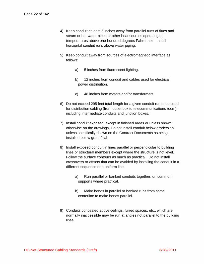
4) Keep conduit at least 6 inches away from parallel runs of flues and
steam or hot-water pipes or other heat sources operating at
temperatures above one-hundred degrees Fahrenheit. Install
horizontal conduit runs above water piping.
5) Keep conduit away from sources of electromagnetic interface as
follows:
a) 5 inches from fluorescent lighting.
b) 12 inches from conduit and cables used for electrical
power distribution.
c) 48 inches from motors and/or transformers.
6) Do not exceed 295 feet total length for a given conduit run to be used
for distribution cabling (from outlet box to telecommunications room),
including intermediate conduits and junction boxes.
7) Install conduit exposed, except in finished areas or unless shown
otherwise on the drawings. Do not install conduit below grade/slab
unless specifically shown on the Contract Documents as being
installed below grade/slab.
8) Install exposed conduit in lines parallel or perpendicular to building
lines or structural members except where the structure is not level.
Follow the surface contours as much as practical. Do not install
crossovers or offsets that can be avoided by installing the conduit in a
different sequence or a uniform line.
a) Run parallel or banked conduits together, on common
supports where practical.
b) Make bends in parallel or banked runs from same
centerline to make bends parallel.
9) Conduits concealed above ceilings, furred spaces, etc., which are
normally inaccessible may be run at angles not parallel to the building
lines.

Page 23 of 162
DC-Net Structured Cabling Standards (Draft) 3/28//2011
10) Wherever practical, route conduit with adjacent ductwork or piping
and support on common racks. Base required strength of racks,
hangers, and anchors on combined weights of conduit and piping.
11) Where conduits cross building expansion joints, use suitable sliding or
offsetting expansion fittings. Unless specifically approved for bonding,
use a suitable bonding jumper.
12) Support conduits:
a) Provide anchors, hangers, supports, clamps, etc. to
support conduits from the structures in or on which they are
installed. Do not space supports farther apart than five feet.
b) Provide sufficient clearance to allow conduit to be added to
racks, hangers, etc. in the future.
c) Support conduit within three (3) feet of each outlet box,
junction box, gutter, panel, fitting, etc.
13) Ream conduits to eliminate sharp edges and terminate with metallic
insulated grounded throat bushings. Seal each conduit after
installation (until cable is installed) with a removable mechanical-type
seal to keep conduits clean, dry and prevent foreign matter from
entering conduits.
14) Install a pull string in each conduit.
15) For conduits entering through the floor of a telecommunications room,
terminate conduits 6‖ above the finished floor.
16) Do not install communications conduits in wet, hazardous or corrosive
locations.
17) Where conduit is shown embedded in masonry, embed conduit in the
hollow core of the masonry. Horizontal runs in the joint between
masonry units are not permitted.
18) Where conduit is shown embedded in concrete, embed conduit a
minimum of two inches from the exterior of the concrete. Do not place
conduit in concrete less than 4 inches thick.

Page 24 of 162
DC-Net Structured Cabling Standards (Draft) 3/28//2011
a) One inch trade size conduit shall be used. Conduits sized
smaller than one inch trade size conduit are not permitted
embedded in concrete without approval from the Owner.
b) Run conduit parallel to main reinforcement.
c) Conduit crossovers in concrete are not permitted
19) Where conduit exits from grade or concrete, provide a rigid steel
elbow and adapter.
20) Where conduit enters a space through the floor and terminates in that
space, terminate the conduit at 6‖ above the finished floor.
21) Where conduits terminate at a cable tray, the conduits shall be
consistently terminated no more than 8‖ from the cable tray, and have
a visually uniform appearance.
22) Where several circuits follow a common route, stagger pullboxes or
fittings.
23) Where several circuits are shown grouped in one box, individually
fireproof each conduit.
24) Bend and offset metal conduit with standard factory sweeps or conduit
fittings. Keep legs of bends in the same plane and straight legs of
offsets parallel, unless otherwise indicated.
a) Conduit Sweeps:
1) Sweeps shall exceed 90 degrees
2) Do not exceed 180 degrees for the sum total of conduit
sweeps for a section of conduit (between conduit
termination points).
3) Sweep radius shall be at least 10 times the internal
diameter of the conduit.
4) 90-degree condulets (LB’s) and electrical elbows are
not acceptable.
b) Factory-manufactured sweeps are required for bends in
conduit larger than 1-¼‖ trade size.

Page 25 of 162
DC-Net Structured Cabling Standards (Draft) 3/28//2011
c) For bends in 1 ¼‖ trade size conduit and larger, field-
manufactured bends (using a hydraulic bender with a 1 ¼‖
boot) are permitted only when factory-manufactured sweeps
are not suitable for the conditions. In all other cases, factory-
manufactured sweeps are required. ―Hickey-bender‖ use is
prohibited.
25) Connect conduit to enclosures, cabinets and boxes with double
locknuts and with insulating type bushings. Use grounding type
bushings where connecting to concentric or eccentric knockouts.
Make conduit connections to enclosures at the nearest practicable
point of entry to the enclosure area where the devices are located to
which the circuits contained in the conduit will connect.
26) Penetrations for raceways:
a) Do not bore holes in floor and ceiling joists outside center
third of member depth or within two feet of bearing points.
Holes shall be 1-¼‖ diameter maximum.
b) Penetrate finished walls and finished surfaces with a PVC
or sheet metal sleeve with an interior diameter (ID) at least
1/4" greater than the outer diameter (OD) of the conduit, set
flush with walls, pack with fiberglass, seal with silicone sealant.
c) Penetrate poured-in-place walls and free slabs with a cast
iron sleeve (or Schedule 40 PVC black pipe sleeve for above-
grade only) with retaining ring or washer. Set sleeves flush
with forms or edges of slab. Pack around conduit with
fiberglass and seal with silicone sealant.
27) Raceway terminations and connections:
a) Join conduits with fittings designed and approved for the
purpose and make joints tight. Do not use set indent-type or
screw-type couplings.
b) Make threaded connections waterproof and rustproof by
applying a watertight, conductive thread compound. Clean
threads of cutting oil before applying thread compound.
c) Make conduit terminations tight. Use bonding bushings or
wedges at connections subject to vibration. Use bonding
jumpers where joints cannot be made tight.

Page 26 of 162
DC-Net Structured Cabling Standards (Draft) 3/28//2011
d) Cut ends of conduit square using a hand saw, power saw
or pipe cutter. Ream cut ends to remove burrs and sharp
ends. Where conduit threads are cut in the field, cut threads
to have same effective length, same thread dimensions and
same taper as specified for factory-cut threads.
e) Provide double locknuts and insulating bushings at conduit
connections to boxes and cabinets. Align raceways to enter
squarely and install locknuts with dished part against the box.
Use grounding type bushings where connecting to concentric
or eccentric knockouts.
f) Where conduits are terminated with threaded hubs, screw
raceways or fittings tightly into the hub so the end bears
against the wire protection shoulder. Where chase nipples are
used, align raceways so the coupling is square to the box and
tighten the chase nipple so no threads are exposed.
28) Install conduit sealing fittings according to manufacturer's written
instructions. Locate fittings at suitable, approved, and accessible
locations and fill them with UL-listed sealing compound. For
concealed conduits, install each fitting in a flush steel box with a blank
cover plate having a finish similar to that of adjacent plates or
surfaces. Install raceway sealing fittings at the following points:
a) Where conduits pass from warm to cold locations, such as
the boundaries of air conditioned or refrigerated spaces and
where conduits enter or exit buildings from outdoor areas,
including underground ducts or conduit runs.
b) Where otherwise required by the NEC.
29) Conduits shall be clean and dry.
C. Sleeves:
1) Provide sleeves where required, sized as noted on the Contract
Documents. Where not noted, sleeve sizing shall be determined by
the type and quantity of cable to be routed through the sleeve per
TIA/EIA 569A cable capacity standards, plus an additional 20% for
future expansion.
2) Provide core drilling where required for installation.

Page 27 of 162
DC-Net Structured Cabling Standards (Draft) 3/28//2011
3) Seal between sleeve and wall or floor in which the sleeve is installed.
Firestop all penetrations to restore wall or floor to pre-penetration fire-
rating.
D. Surface Raceway:
1) Provide surface raceway for all surface mounted telecommunications
outlet boxes and as shown on the Contract Documents.
2) Surface raceway shall be routed parallel to and perpendicular to
surfaces or exposed structural members, and follow surface contours.
3) Surface raceway color shall match as closely as possible the existing
wall finish. Do not paint Surface Raceway.
4) Surface raceway systems shall be completely installed, including
insulating bushings and inserts as required by manufacturer’s
installation requirements. Unused openings in the surface raceway
shall be closed using manufactured fittings.
5) Surface raceway shall have a minimum two inch radius control at all
bend points.
6) Surface raceway shall be securely supported by screws or other
anchor-type devices at intervals not exceeding 10 feet and with no
less than two supports per straight raceway section. Surface raceway
shall be securely supported in accordance with the manufacturer’s
requirements. Tape and glue are not acceptable support methods.
7) Mechanically and electrically continuous surface raceway shall be
bonded and grounded to the Telecommunications Grounding system.
E. Outlet Boxes:
1) Provide outlet boxes and covers as shown on the Contract
Documents and as needed. Verify that the appropriate cover type
and depth is provided for each type of wall and finish. Provide
extension rings as needed.
2) Coordinate box locations with building surfaces and finishes to avoid
bridging wainscots, joints, finish changes, etc.
3) Install boxes in dry locations (not wet, corrosive, or hazardous).

Page 28 of 162
DC-Net Structured Cabling Standards (Draft) 3/28//2011
4) Attach boxes securely to building structure with a minimum of two
fasteners. Provide attachments to withstand a force of one hundred
pounds minimum, applied vertically or horizontally.
5) Install boxes at the following heights to the bottom of the box, except
where noted otherwise:
a) Wall mounted telephones: 48‖ above finished floor.
b) Workstation outlets: 18‖ above finished floor.
c) Place boxes for outlets on cabinets, countertops, shelves,
and similar boxes located above countertops two inches above
the finished surface or two inches above the back splash.
Coordinate and verify size, style, and location with the supplier
or installer of these items prior to outlet box installation.
6) Recessed mounted outlet boxes:
a) Recess boxes in the wall, floor, and ceiling surfaces in
finished areas. Set boxes plumb, level, square and flush with
finished building surfaces within one-sixteenth inch for each
condition. Set boxes so that box openings in building surfaces
are within one-eighth inch of edge of material cut-out and fill
tight to box with building materials. Single gang opening shall
extend at least to the finished wall surface and extend not
more than 1/8 inch beyond the finished wall surface. Provide
backing for boxes using structural material to prevent rotation
on studs or joists.
b) Install floor boxes level and adjust to finished floor surface.
7) Surface-mounted outlet boxes:
a) For boxes surface-mounted on finished walls, provide
Wiremold outlet box or equivalent. Cut box as necessary to
accept conduit.
b) For boxes surface-mounted on unfinished walls (i.e.
electrical rooms, mechanical rooms), provide 4‖x4‖ (minimum)
outlet box with single gang cover.
F. Floor Boxes:
Page 29 of 162
DC-Net Structured Cabling Standards (Draft) 3/28//2011
1) Provide floor boxes as shown on the Contract Documents.
2) Set device boxes plumb, level, square and flush with floor, within
1/16‖ tolerance for each condition.
3) For floor boxes with combined power and telecommunications circuits,
provide metal dividers to separate power from telecommunications
circuits.
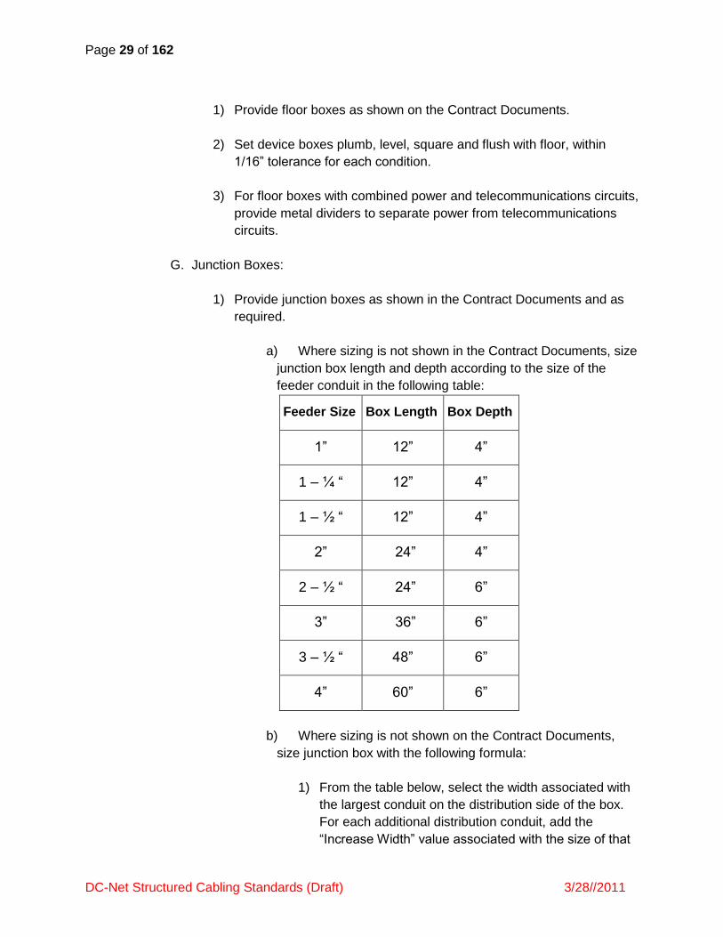
G. Junction Boxes:
1) Provide junction boxes as shown in the Contract Documents and as
required.
a) Where sizing is not shown in the Contract Documents, size
junction box length and depth according to the size of the
feeder conduit in the following table:
Feeder Size Box Length Box Depth
1‖ 12‖ 4‖
1 – ¼ ― 12‖ 4‖
1 – ½ ― 12‖ 4‖
2‖ 24‖ 4‖
2 – ½ ― 24‖ 6‖
3‖ 36‖ 6‖
3 – ½ ― 48‖ 6‖
4‖ 60‖ 6‖
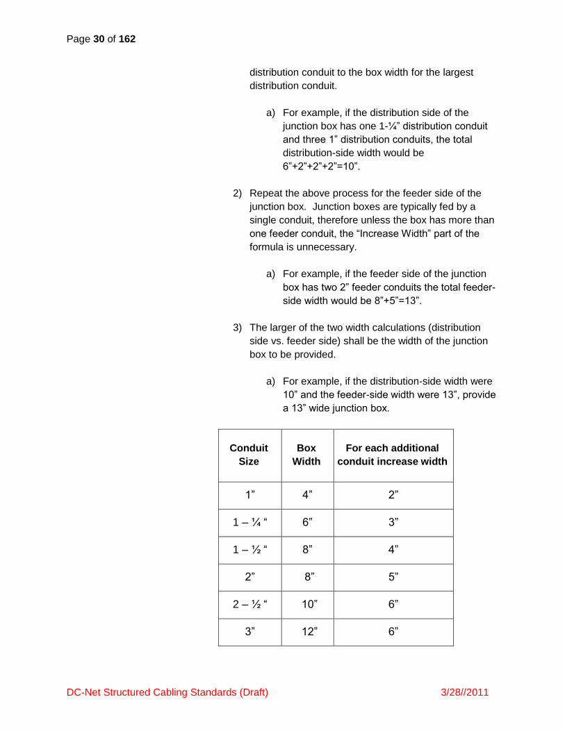
b) Where sizing is not shown on the Contract Documents,
size junction box with the following formula:
1) From the table below, select the width associated with
the largest conduit on the distribution side of the box.
For each additional distribution conduit, add the
―Increase Width‖ value associated with the size of that
Page 30 of 162
DC-Net Structured Cabling Standards (Draft) 3/28//2011
distribution conduit to the box width for the largest
distribution conduit.
a) For example, if the distribution side of the
junction box has one 1-¼‖ distribution conduit
and three 1‖ distribution conduits, the total
distribution-side width would be
6‖+2‖+2‖+2‖=10‖.
2) Repeat the above process for the feeder side of the
junction box. Junction boxes are typically fed by a
single conduit, therefore unless the box has more than
one feeder conduit, the ―Increase Width‖ part of the
formula is unnecessary.
a) For example, if the feeder side of the junction
box has two 2‖ feeder conduits the total feeder-
side width would be 8‖+5‖=13‖.
3) The larger of the two width calculations (distribution
side vs. feeder side) shall be the width of the junction
box to be provided.
a) For example, if the distribution-side width were
10‖ and the feeder-side width were 13‖, provide
a 13‖ wide junction box.
Conduit
Size
Box
Width
For each additional
conduit increase width
1‖ 4‖ 2‖
1 – ¼ ― 6‖ 3‖
1 – ½ ― 8‖ 4‖
2‖ 8‖ 5‖
2 – ½ ― 10‖ 6‖
3‖ 12‖ 6‖

Page 31 of 162
DC-Net Structured Cabling Standards (Draft) 3/28//2011
3 – ½ ― 12‖ 6‖
4‖ 15‖ 8‖
2) A junction box may not be substituted for a 90-degree bend. 90
degree condulets (LB’s) are not acceptable.
3) Install junction boxes in a location readily accessible both at time of
construction and after building occupation. Do not install junction
boxes in inaccessible interstitial building spaces.
4) Where junction boxes are to be mounted on ceiling structure above
ceiling grid, do not mount higher than 4’ above grid.
5) Install hinged-cover enclosures and cabinets plumb, and supported at
each corner.
6) Install junction boxes so that the access door opens from the side
where the cable installer will normally work – typically from the bottom
(floor side) of the box.
a) Where a junction box is installed in a ceiling space,
coordinate with other trades to provide full access to the
junction box door and adequate working room for both the
installation personnel and for proper looping of cable during
installation.
b) Provide a lockable access cover (or junction box door if
junction box is exposed) in hard lid ceilings.
7) Install junction boxes such that conduits enter and exit at opposite
ends of the box as follows:
Junction Box Junction Box
Correct Installation Incorrect Installation
Home Run Conduit Home Run Conduit

Page 32 of 162
DC-Net Structured Cabling Standards (Draft) 3/28//2011
H. Pull Boxes:
1) Provide pull boxes as shown on the Contract Documents and as
required.
a) Where sizing is not shown on the Contract Documents,
size pull boxes as follows:
Size of Largest Conduit Box Width Box Length Box Depth
1‖ 4‖ 12‖ 4‖
1 – ¼‖ 6‖ 12‖ 4‖
1 – ½‖ 8‖ 12‖ 4‖
2‖ 8‖ 24‖ 4‖
2 – ½‖ 10‖ 24‖ 6‖
3‖ 12‖ 36‖ 6‖
3 – ½‖ 12‖ 48‖ 6‖
4‖ 15‖ 60‖ 6‖
b) Where a pull box is required with conduits 1‖ or smaller, an
outlet box may be used as a pull box. Where outlet boxes are
used as pull boxes, the outlet boxes shall be dedicated for use
as a pull box and shall not host cable termination hardware.
2) A pull box may not be substituted for a 90-degree bend. 90 degree
condulets (LB’s) are not acceptable.
3) Install pull boxes in an accessible location, readily accessible both at
time of construction and after building occupation. Do not install pull
boxes in inaccessible interstitial building space.
4) Where pull boxes are to be mounted on ceiling structure above ceiling
grid, do not mount higher than 4’ above grid (mount on wall instead).
5) Install hinged-cover enclosures and cabinets plumb, and supported at
each corner.
6) Install pull boxes so that the access door opens from the side where
the cable installer will normally work (typically from the bottom, or floor
side, of the box).
a) Where a pull box is installed in a ceiling space, provide full
access to the junction box door and adequate working room
for both the installation personnel and for proper looping of
cable during installation.
Page 33 of 162
DC-Net Structured Cabling Standards (Draft) 3/28//2011
b) Provide a lockable access cover (or pull box door if pull
box is exposed) in hard lid ceilings.
7) Install pull boxes such that conduits enter and exit at opposite ends of
the box as follows:
I. Firestopping:
1) Only employees trained/certified by the firestopping manufacturer
shall apply firestopping materials.
2) Maintain fire rating of penetrated fire-rated walls. Firestop and seal
each penetration made during construction.
a) Provide firestopping material for through and membrane
penetrations of fire-rated barriers.
b) Installation shall be performed in strict accordance with
manufacturer’s detailed installation procedures.
c) Install firestops in accordance with fire test reports, fire
resistant requirements, acceptable sample installations,
manufacturer’s recommendations, local fire and building
authorities and applicable codes and standards referenced in
PART 1-1.2 REFERENCES. Apply all sealing material in a
manner acceptable to the local fire and building authorities.
J. Grounding/Bonding: Grounding and Bonding work shall comply with Uniform
Fire Code, National Electric Code

Page 34 of 162
DC-Net Structured Cabling Standards (Draft) 3/28//2011
SECTION 270536 Cable Trays for Communications Systems
PART 1 – GENERAL
1.1 SUMMARY
A. Provide all materials and labor for the installation of a cable tray system to be
utilized for communications infrastructure. This section includes
requirements for providing a cable tray system for communications circuits.
1.2 REFERENCES
A. The pertinent portions of the following specifications, standards, regulations
and codes shall be incorporated by reference into these specifications.
1) General
a) National Electrical Code (NEC)
b) National Electrical Safety Code (NESC)
c) Occupational Safety and Health Act (OSHA)
d) ASTM A123 – Specification for Zinc (Hot Galvanized)
Coatings on products Fabricated from Rolled. Pressed, and
Forged Steel Shapes, Plates, Bars, and Strip.
e) ASTM A653 – Specification for Steel Sheet, Zinc-Coated
(Galvanized) by the Hot Dip Process, Structural (Physical)
Quality.
f) ASTM A1011 – Specification for Steel, Sheet and Strip,
Hot-Rolled, Carbon, Structural, High-Strength Low-Alloy and
High-Strength Low-Alloy with improved Formability.
g) ASTM A1008 – Specification for Steel. Sheet, Cold-Rolled,
Carbon, Structural, High-Strength Low-Alloy and High-
Strength Low-Alloy Formability.
h) ASTM B633 – Specification for Electrodeposited Coatings
of Zinc on Iron and Steel.
i) NEMA VE 1 – Metallic Cable Tray Systems

Page 35 of 162
DC-Net Structured Cabling Standards (Draft) 3/28//2011
j) NEMA VE 2 – Cable Tray Installation Guidelines
2) Communications
a) TIA/EIA – 568: Commercial Building Telecommunications
Cabling Standard.
b) TIA/EIA – 569: Commercial Building Standard for
Telecommunication Pathways and Spaces.
c) TIA/EIA – 606: The Administration Standard for the
Telecommunications Infrastructure of Commercial Buildings.
d) TIA/EIA – 607: Commercial Building Grounding and
Bonding Requirements for Telecommunications.
e) ISO/IEC IS 11801: Generic Cabling for Customer
Premises.
f) BICSI TCIM: BICSI Telecommunications Cabling
Installation Manual.
g) BICSI TDMM: BICSI Telecommunications Distribution
Methods Manual.
1.3 DEFINITIONS
A. ―EMT‖ shall mean Electrical Metallic Tubing.
B. ―RMC‖ shall mean Rigid Metal Conduit.
C. ―Raceway‖ shall mean any enclosed channel for routing wire, cable or
busbars.
D. ―TMGB‖ shall mean Telecommunications Main Grounding Busbar. There is
typically one (1) TMGB per building, located in the main telecommunications
room. This busbar is directly bonded to the electrical service ground.
E. ―TGB‖ shall mean Telecommunications Grounding Busbar. There is typically
one (1) TGB per Telecommunications Room (TR). The TGB is connected
both to the TMGB and to the building structural steel or other permanent
metallic systems.

Page 36 of 162
DC-Net Structured Cabling Standards (Draft) 3/28//2011
F. ―TBB‖ shall mean Telecommunications Bonding Backbone. The TBB is a
conductor used to connect TMGBs to TGBs.
G. ―Pullbox‖ shall mean a metallic box with a removable cover, used to assist
pulling cable through conduit runs longer than 100’ or in which there are more
than 180 degrees of bends. Pullboxes shall have no more than one (1)
conduit entering and one (1) conduit exiting the box.
H. ―Junction Box‖ shall mean a pullbox wherein a conduit run transitions from a
feeder conduit to multiple distribution conduits.
1.4 SYSTEM DESCRIPTION
A. Furnish, install, and place into adequate and successful operation all
materials, devices, and necessary appurtenances to provide a complete,
permanent Cable Tray Infrastructure for Telecommunications Circuits as
specified in the Contract Documents. The Cable Tray System shall support
an ANSI/TIA/EIA and ISO/IEC compliant telecommunications Structured
Cabling System (SCS).
B. The work shall include materials, equipment and apparatus not explicitly
mentioned herein or noted in the Contract Document but which are essential
to make a complete working ANSI/TIA/EIA and ISO/IEC compliant Cable
Tray System.
1.5 SUBMITTAL INFORMATION
A. Product Data Submittals: Provide submittal information for evaluation before
materials are delivered to the site. Provide product data submittals for all
products at the same time.
1) Submit a letter stating that materials will be provided as indicated, and
specifically list any items that will not be provided as indicated. The
letter shall also state that the Contractor has reviewed the indicated
items and has come to an understanding that they are applicable to
the project in all aspects.
2) For those items noted as ―Or Equal‖ and which are not being provided
as specifically named, submit standard cut sheets or other descriptive
information, along with a separate written description detailing the
reason(s) for the substitution.

Page 37 of 162
DC-Net Structured Cabling Standards (Draft) 3/28//2011
3) Provide standard manufacturer’s cut sheets and Operating and
Maintenance (O&M) instructions at the time of submittal review for
each device in the system. These instructions shall detail how to
install and service the equipment and shall include information
necessary for rough-in and preparation of the building facilities to
receive said materials.
B. Closeout Submittals:
1) O&M Manual- At the completion of the project, the contractor shall
submit and O&M to the DC-Net project Manager, reflecting any
changes that occurred during the process of construction.
2) Records- Maintain at the project site a minimum of one set of
Drawings, Specifications, and Addenda. Drawings shall consist of
redline markups, specifications and spreadsheets.
a) Document changes to the system from that initially shown
from the Contract Documents, and clearly identify component
labels and identifiers on Drawings.
b) Keep Drawings at the job site and make available to DC-
Net and or Designer at all times.
c) Keep Drawings current throughout the progress of
construction. (―Current‖ is defined as not more than one (1)
week behind actual construction).
d) Show identifiers for major infrastructure components on
Drawings.
PART 2- PRODUCTS
2.1 GENERAL
A. Materials shall consist of tray sections, tray fittings, connectors, supports,
expansion joints, barrier strips, radius drops, bonding conductors and other
incidentals and accessories as required for a complete, permanent Cable
Tray Infrastructure. Provide all incidental and or miscellaneous hardware not
explicitly shown in the Contract Documents but that is required for a fully
operational system.

Page 38 of 162
DC-Net Structured Cabling Standards (Draft) 3/28//2011
B. Physically verify existing site conditions prior to purchase and delivery of
materials.
C. Cable Tray components must be manufactured by a single manufacturer.
Components shall not be intermixed between different manufacturers.
D. For a given manufacturer, all components shall be part of a single cable tray
product line- components shall not be intermixed between a manufacturer’s
cable tray product line.
2.2 MATERIALS AND FINISH
A. Welded wire: Cable Tray shall be constructed of a welded wire mesh (high
strength steel wires) with a continuous safety edge wire lip. Cable tray shall
be complete with all tray supports, materials, and supplementary and
miscellaneous hardware required for a complete cable tray system.
1) Finish: Carbon steel with electro-plated zinc galvanized finish.
2) Width: Width shall be as shown on the Contract Documents. Where
cable tray width is not shown in the Contract Documents, it shall be
sized according to the amount of cable to be placed in the trays (as
shown in the Contract Documents) plus an additional 20% for future
expansion.
3) Depth: minimum of two (2) inches.
4) Mesh: 2 x 4 inches.
5) Fittings: Fittings shall be field fabricated from straight sections using
manufacturer-approved tools and in accordance with the
manufacturer’s instructions.
B. Grounding/Bonding: In accordance with ANSI/NFPA 70 Section 318-7, cable
tray shall be complete with bolted splicing hardware for grounding/bonding
throughout the entire cable tray system.
2.3 FIRESTOPPING MATERIALS
A. Firestopping material: Conform to both Flame (F) and Temperature (T)
ratings as required by local building codes and as tested by nationally
accepted test agencies per ASTM E814 or UL1479 fire test in a configuration
that is representative of the actual field conditions.
2.4 LABELING AND ADMINISTRATION

Page 39 of 162
DC-Net Structured Cabling Standards (Draft) 3/28//2011
A. Labels: As recommended in ANSI/TIA/EIA 606. Permanent (i.e. not subject to
fading or erasure), permanently affixed and created by hand carried label
maker or a computer/software-based label making system. Handwritten
labels will not be acceptable.
PART 3 – EXECUTION
3.1 GENERAL
A. The Contractor is solely responsible for the safety of the public and workers
in accordance with all applicable rules, regulations, building codes and
ordinances.
B. All work shall comply with applicable safety rules and regulations including
OSHA. All work shall comply with the requirements of the National Electrical
Safety Code (NESC) and the NEC except where local codes and or
regulations are more stringent, in which case the local codes and or
regulations shall govern.
C. All work shall comply with the standards, references and codes listed in
PART 1.2 REFERNCES above. Where questions arise regarding which
standards, references, or codes apply, the more stringent shall prevail.
D. All work shall comply with the requirements and recommendations of the
product manufacturers. Where questions arise regarding which requirements
and recommendations apply, the more stringent shall prevail.
E. Replace and or repair to original (or better) condition any existing structures,
materials, equipment, etc. inadvertently demolished or damaged by the
Contractor during the course of construction at no additional cost to DC-Net.
F. Install the cable tray system in a manner ensuring that telecommunications
circuits, when installed, are able to fully comply with the ANSI/TIA/EIA and
other references listed in PART 1.2 REFERENCES, above.
G. Remove all surplus material and debris from job site and dispose of them
legally.
3.2 INSTALLATION
A. Provide cable tray, in the locations and widths shown on the Contract
Documents and in accordance with manufacturer's requirements and industry
practices (NEMA VE 2). Ensure that the cable tray equipment complies with
the requirements of NEC, and applicable portions of NFPA 70B and NECA’s

Page 40 of 162
DC-Net Structured Cabling Standards (Draft) 3/28//2011
―Standards of Installation‖ pertaining to general electrical installation
practices.
1) Cable tray shall be installed plumb, level and square with finished
building surfaces.
2) Provide factory-manufactured connection hardware between each
cable tray segment. Cable tray segments shall be mutually aligned.
Connection hardware shall be installed according to the
manufacturer’s requirements.
3) Cable tray elevation changes shall be gradual.
B. Slots/sleeves: Provide slots/sleeves where required and where shown on the
Contract Documents. Provide hammer-drilling, core drilling and saw cutting
where required for installation. Seal and firestop (firestop only if fire rated
barrier) between slot/sleeve and cable tray.
C. Cable Tray Routing:
1) Route cable tray as shown on the Contract Documents. Where not
shown on the Contract Documents, route cable tray in the most direct
route possible, parallel to building lines.
2) Do not route cable tray through areas in which flammable material
may be stored or through wet, hazardous or corrosive areas.
D. Cable Tray Clearance Requirements:
1) Clearance requirements for cable tray accessibility:
a) Maintain a clearance of 6‖ between top of cable tray and
ceiling structure or other equipment or raceway.
b) Maintain a clearance of 8‖ between at least one side of
cable tray and nearby objects.
c) Maintain a clearance of 6‖ between bottom of cable tray
and ceiling grid or other equipment or raceway.
2) Clearance requirements from sources of electromagnetic interference
(EMI):

Page 41 of 162
DC-Net Structured Cabling Standards (Draft) 3/28//2011
a) Maintain a clearance of 5‖ or more from fluorescent
lighting.
b) Maintain a clearance of 12‖ or more from conduit and
cables used for electrical power distribution.
c) Maintain a clearance of 48‖ or more from motors or
transformers.
d) Pathways shall cross perpendicularly to electrical power
cables or conduits.
3) Maintain a clearance of at least 6 inches from parallel runs of flues
and steam or hot- water pipes or other heat sources operating at
temperatures above one-hundred degrees Fahrenheit.
E. Cable Tray Fittings: Provide field-fabricated fittings from straight sections of
cable tray using manufacturer-approved tools and in accordance with
manufacturer’s instructions. Bends shall be long radius. Short radius bends
and T-sections shall not be used unless specifically called out on the Contract
Documents.
F. Cable tray supports shall be provided according to the manufacturer’s
recommendations.
1) Supports shall be attached to structural ceiling or walls with hardware
or other installation and support aids specifically designed for the
cable tray and designed to support the cable tray’s weight and
required cable weight and volume.
2) Where cable trays abut walls, provide wall-mounted supports.
3) Do not attach cable tray supports to ceiling support system or other
mechanical support systems.
4) Trays shall be supported at 5 foot intervals minimum, or more
frequently if required by the manufacturer.
G. Load span criteria: Install tray supports in accordance with the load criteria of
L/240, and as shown on the Contract Documents.
H. Cable tray shall be installed free of burrs, sharp edges, or projections which
may damage cable insulation.

Page 42 of 162
DC-Net Structured Cabling Standards (Draft) 3/28//2011
I. Wire-type cable tray shall be cut with a manufacturer-approved cutter with
―offset cutting blade‖ jaws and a minimum 24 inch handle.
1) The choice and position of the jaws at the point where the cut is to be
made shall allow shearing as close as possible to the intersection of
the steel wires.
2) Cuts shall ensure the integrity of the galvanic protective layer.
J. Expansion Joints: Provide cable tray sliding or offsetting expansion
joints/fittings where cable tray crosses building expansion joints in addition to
where shown on the Contract Documents. Provide bonding jumper except
where expansion joints are explicitly approved for bonding.
K. Thermal contraction and expansion: Install cable tray sections with gap
settings between cable tray sections that are appropriate for the range of
thermal expansion and contraction expected for the space during
construction and also during normal occupancy and operation.
L. Barrier Strips: Provide barrier strips as recommended by manufacturer.
M. Radius Drops: Provide cable tray radius drops where cable trays cross other
telecommunications cable trays or ladder rack in addition to where shown on
the Contract Documents.
3.3 GROUNDING AND BONDING
A. Grounding/Bonding: Grounding and bonding work shall comply with the
Uniform Building Code, Uniform Fire Code, National Electrical Code, and UL
467, ANSI/TIA/EIA standards and the references listed in PART 1.2 –
REFERENCES above, as well as local codes which may specify additional
grounding and/or bonding requirements.
B. Bond metallic raceway (including cable tray) together and to the nearest TGB
(as provided under Division 27 Section — ―Grounding and Bonding for
Communications Systems‖). Ensure that bonding breaks through paint to
bare metallic surface of painted metallic hardware.
C. Cable tray bonding splices: Provide cable tray splices according to
manufacturer requirements to create a continuous bonding conductor
throughout the entire cable tray.
D. Bonding Conductors:

Page 43 of 162
DC-Net Structured Cabling Standards (Draft) 3/28//2011
1) Bond distribution conduits to cable tray.
2) Provide bonding jumpers at expansion joints, sleeves and any other
locations where electrical continuity is interrupted.
3) Provide bonding conductor between cable tray and the electrical
power distribution system grounding infrastructure.
3.4 FIRESTOPPING
A. Only employees trained/certified by the firestopping manufacturer shall apply
firestopping materials.
B. Maintain the fire rating of all penetrated fire barriers. Fire stop and seal all
penetrations made during construction.
1) Provide firestopping material for through and membrane penetrations
of fire-rated barriers.
2) Install firestops in strict accordance with manufacturer’s detailed
installation procedures.
3) Install firestops in accordance with fire test reports, fire resistance
requirements, acceptable sample installations, manufacturer’s
recommendations, local fire and building authorities, and applicable
codes and standards referenced in PART 1.2 – REFERENCES.
Apply sealing material in a manner acceptable to the local fire and
building authorities.
4) For demolition work, apply firestopping to open penetrations in fire
rated barriers where cable is removed. Apply firestopping regardless
of whether or not the penetrations are used for new cable or left
empty after construction is complete.
5) Firestopping material used to seal open penetrations through which
cable passes shall be re-usable/re-enterable.
3.5 CLEANING AND PROTECTION
A. After completion of installation, including outlet fittings and devices, inspect
exposed finish. Remove burrs, dirt, and construction debris and repair
damaged finish, including chips, scratches, and abrasions.
B. Provide final protection and maintain conditions, in a manner acceptable to
manufacturer and in accordance with accepted industry practice, that ensure

Page 44 of 162
DC-Net Structured Cabling Standards (Draft) 3/28//2011
coatings, finishes, and cabinets are without damage or deterioration at the
time of Substantial Completion.
1) Repair damage to galvanized finishes with zinc-rich paint
recommended by manufacturer.
2) Repair damage to PVC or paint finishes with matching touchup
coating recommended by manufacturer.
3.6 TESTING
A. Test cable trays to ensure electrical continuity of bonding and grounding
connections. Demonstrate compliance with maximum grounding resistance
per NFPA 70B, Chapter 18.
3.7 LABELING AND ADMINISTRATION
A. Provide the following two labels, alternating one label every 10 feet, along the
entire length of the cable tray:
1) Label #1: Label shall read ―TELECOMMUNICATIONS / LOW
VOLTAGE CABLING ONLY‖.
2) Label #2: Label shall read ―WARNING! CABLE TRAY SERVES AS A
TELECOMMUNICATIONS BONDING CONDUCTOR. DO NOT
DISCONNECT!‖
SECTION 270543 Underground Ducts and Raceways for Communications
Systems
PART 1 – GENERAL
1.1 SCOPE
A. Provide all services, labor, materials, tools, and equipment necessary for the
complete and proper installation of exterior telecommunications pathways as
specified in the contract.
B. This section includes the minimum requirements and installation methods for
the following:
1) Cutting and patching of Asphalt and or Concrete.
2) Trenching and Excavation.

Page 45 of 162
DC-Net Structured Cabling Standards (Draft) 3/28//2011
3) Underground Conduit systems.
4) Horizontal Drilling (commonly referred to as Directional Boring or
Horizontal Boring).
1.2 QUALITY ASSURANCE
A. Installation for all exterior telecommunications pathways shall be performed in
a professional and workmanlike manner. All construction methods that are
not specified in the Contract Documents shall be subject to the control of DC-
Net.
B. Equipment and materials shall consist of the quality and manufacturer
indicated in the contract. The equipment specified is based on the
acceptable manufactures listed in the contract.
C. Materials and work specified herein shall conform with the applicable
requirements of:
1) ANSI/NFPA 70
2) IEEE/NESC
3) NEMA
a) NEMA, RN1, PVC Externally Coated Galvanized Rigid
Steel Conduit and Intermediate Metal Conduit.
b) NEMA, TC3, PVC Fittings for use with Rigid PVC Conduit
and Tubing.
c) NEMA, TC6, PVC and ABS Plastic Utilities Duct for
Underground Installation.
d) NEMA, TC8, Extra Strength PVC Plastic Utilities Duct for
Underground Installation.
e) NEMA, TC9, Fitting for ABS and OVC Plastic
Communications Duct and Fittings for Underground
Installation.
f) NEMA, TC10, PVC and ABS Plastic Communications Duct
and Fittings for Underground Installation.

Page 46 of 162
DC-Net Structured Cabling Standards (Draft) 3/28//2011
4) UL Standards
a) UL 6 Rigid Metal Electrical Conduit
b) UL 651 Schedule 40 and 80 PVC Conduit
5) ANSI-C80.2 Specification for Rigid Steel Conduit, Enameled.
6) ANSI/TIA-569-B Commercial Building Standard for
Telecommunications Pathway and Spaces.
7) ANSI/TIA-607 Commercial Building Grounding and Bonding
Requirements for Telecommunications.
8) ANSI/TIA-758-A Customer Owned Outside Plant Telecommunications
Cabling Standard.
9) BICSI TDMM
10) BICSI Outside Plant Design Reference Manual
D. For horizontal drilling, the Contractor shall follow all safeguards necessary to
ensure that crucial aspects of proper directional bore installation are
controlled.
E. Personnel for horizontal directional drilling shall be fully trained in their
particular duties as part of the drilling team.
PART 2- PRODUCTS
2.1 TRENCH/BACKFILL MATERIALS
A. Trenching and Excavation Backfill: Select fill materials as specified in Section
02221
B. Concrete Slurry: Select Flow Fill as specified in Section 02221
C. Concrete Pavement: Select concrete paving materials as specified in Section
02520

Page 47 of 162
DC-Net Structured Cabling Standards (Draft) 3/28//2011
D. Asphalt Pavement: Select asphaltic paving materials as specified in Section
02513
2.2 CONDUIT SYSTEM
A. Non-Metallic Conduit:
1) PVC plastic pipe, ASTM D1785, Schedule 40 or 80, Type PVC 1120
2) 4‖ 45 Degree Fiberglass Bend: FRE Composite Inc., 30-4032 Elbow
IPS
3) 4‖ 90 Degree Fiberglass Bend: FRE Composite Inc., 30-4030 elbow
IPS
B. Metallic Conduit: GRC with PVC coating (for building entrances, offsets and
sweep bends) within 50 feet of the building protection.
C. Conduit Joint Couplings:
1) PVC non-metallic fittings must be installed with solvent applied
couplings.
2) Approved transition couplings shall be used to connect metal to
plastic (PVC) conduits.
3) Couplings shall be threaded and or glued to provide a watertight seal
at conduit junctions.
D. Outside Pull-Box: Minimum 14 gauge galvanized steel with weatherproof
locking cover and hardware surface mounting as specified in the contract.
Dimensions as specified in the contract.
2.3 CABLE ROUTING HARDWARE
A. Cable Rack with Support Hardware as Required
B. Cable Rack Steps/Hooks
2.4 HORIZONTAL DRILLING EQUIPMENT
A. The horizontal directional drilling equipment shall have a drilling device of
appropriate capacity to perform the bore; it shall have a guidance system to
precisely guide boring operations, and trained personnel to operate said
system.

Page 48 of 162
DC-Net Structured Cabling Standards (Draft) 3/28//2011
B. All equipment shall be in good, safe operating condition with appropriate
supplies, materials and spare hardware on hand to preserve the systems
integrity during the project.
C. The directional drilling apparatus shall consist of hydraulically powered
system to drill into the earth at a variable angle.
1) The apparatus shall be anchored to the ground in order to withstand
any pressures required to complete boring.
2) The hydraulic system shall be free of leaks.
3) The hydraulic power system shall be self-contained with necessary
pressure and volume to power the drilling operation.
D. The Guidance System shall be a proven type and shall be assembled and
operated by personnel certified and experienced with this system.
1) The operator shall be aware of any magnetic anomalies and shall
consider these influences in the operation of the guidance system, if
using a magnetic system.
PART 3 – EXECUTION
3.1 INSPECTION
A. Examine areas and conditions under which the new exterior
telecommunications pathways are to be installed. Provide notification, in
writing, of conditions detrimental to proper completion of the work.
B. Beginning of telecommunications pathway indicates Contractor acceptance of
existing conditions.
3.2 TRENCHING AND BACKFILL
A. Perform all trenching and backfill for new underground conduit system
placement as reflected in the Contract Documents.
B. Perform pavement removal and replacement as specified.
C. Perform pavement marking as required and specified.
D. All utilities to be located by contractor and exposed, if necessary, prior to
construction.

Page 49 of 162
DC-Net Structured Cabling Standards (Draft) 3/28//2011
3.3 CONDUIT SYSTEM PLACEMENT
A. Place new conduit system including handholes and manholes as reflected in
the Contract Documents.
B. No pathways shall have more than 180 degrees of bends.
C. Twelve inch (12 ―) clearance from all utilities is to be preserved. If not
possible conduit to be encased in concrete where proper distance cannot be
achieved.
D. Telecommunication ducts shall cross below gas piping.
E. All conduits must be cleaned thoroughly prior to installation.
F. During construction all ends of conduit shall be plugged to prevent water and
other materials from entering conduits, manholes and buildings.
G. New and reopened trenches located under asphalt roadways shall have
concrete cap or be encased in concrete.
H. Seal all conduit junctions and fittings watertight prior to pouring concrete.
I. Unless otherwise noted on the Contract Documents a minimum of 24‖ depth
shall be required above conduits.
J. Transition to PVC conduit five feet (5’) from building outside wall
penetrations.
K. Bury underground plastic line marker one foot (1’) above telecommunications
conduit.
L. The new conduit shall extend through the wall into the building, tunnel, or
crawl space a minimum of 4‖.
M. Handholes shall be placed with the long dimension in line with the conduit
run. The conduit shall enter opposite ends of the short sides so that the
handhole shall not be used as a 90 degree bend during cable installations.
N. All conduits entering bottom of handhole shall be flush with the inside wall.
Dirt shall be removed 6‖ below the bottom of conduits entering the handhole
and pea-gravel shall be placed on the bottom to aid water dissipation.

Page 50 of 162
DC-Net Structured Cabling Standards (Draft) 3/28//2011
O. The ends of all metallic conduits shall be reamed and bushed.
P. Plug ends of new conduit with watertight conduit plugs, removable conduit
caulking compound, or conduit caps to ensure no foreign matter enters.
All ducts and conduits entering a building must be sealed to prevent intrusion of liquids and
gases. Universal duct plugs are available in a variety of sizes for use in unoccupied ducts and
conduits. In conduits where cable has been installed, conduits can be sealed using Foam
Sealant, Puttys, Cementicious Compounds, and Hydraulic Cement.
All innerducts entering a building must be firestopped in accordance with ASTM E814 and UL
1479.
The preferred method for sealing entrance conduits is Foam Sealant.
To seal conduits entering a building utilizing Foam Sealant (Polywater® Duct Sealant) or
equivalent follow the instructions below:
1.) If conduit has loose debris or rust, use a wire brush to
remove all loose material. Clean cable(s) and conduit.
This will remove contaminants and any residue.
Roughing the surfaces with an abrasive such as steel
wool or sand paper may increase the effectiveness
of the Sealant.
Clean conduit with wire brush.
2.) Create a foam dam by wrapping foam strips around the
cable (s) so that it fills the space between the cable and
the conduit. The tail end of the foam strip should be at
the top of the wrap. The foam strip will slow any existing
water flow and contain the Sealant. Cut all foam to size
as necessary.
Wrap cable (s) with foam strip

Page 51 of 162
DC-Net Structured Cabling Standards (Draft) 3/28//2011
3.) Using a rod or screwdriver, push the foam 5 inches
into the conduit. Make sure there are no voids in the
foam dam for the Sealant to flow through.
Insert foam 5 inches
4.) Wrap a second foam strip around the cable ( If more
than one cable, separate cables with foam strip). Tail
end of the foam strip should be at the top of the wrap.
Push second foam strip into the conduit until the edge
is flush with the conduit entrance.
separate cable (s) with foam
5.) Insert the mixing nozzle into top wrap of foam so
the tip extends into the space between foam strips.
Inject Sealant above cable for better coverage. Use
desired amount of foam Sealant. Rapid injection will
produce better mixing.
Dispensing the Foam Sealant
Sealant will expand fully in 2 to 5 minutes
6.) Remove cartridge and mixing nozzle. Sealant may
seep between the crevices of the foam dam as it
expands. Excess sealant may be trimmed and removed.

Page 52 of 162
DC-Net Structured Cabling Standards (Draft) 3/28//2011
Rising Foam Sealant will harden (set) in 10-15 minutes
7.) After the Sealant has fully set and cured, use a
screwdriver to check for voids in the Sealant. Foam
Sealant should be solid throughout the conduit. If any
holes or voids are detected during the inspection, use a
screwdriver to cut into foam and enlarge a path for new
material. Attach a new mixing nozzle and inject Sealant
directly into the void area.
Checking for voids
3.4 HORIZONTAL DIRECTIONAL DRILLING
A. DC-Net Project Managers shall be notified 48 hours in advance of starting
horizontal directional drilling. The drilling shall not begin until a DC-Net
project manager is on site, and agrees that the proper preparations for the
procedure have been made.
B. No work shall commence until all Traffic Control and proper permits are in
place as applicable for the specific operation.
C. Site Preparation:
1) Prior to any alterations to the work site, all entry and exit points shall
be legibly marked.
2) No alterations to the work site beyond what is required shall be made.
D. Path Survey:
1) The entire drill pathway shall be precisely surveyed with entry and exit
stakes placed at their appropriate locations within the areas reflected
in the Contract Documents.
2) In the case of magnetic guidance systems, the drill pathway must be
surveyed for any surface geomagnetic deviation and or anomalies.
E. All pertinent environmental regulations shall be observed.

Page 53 of 162
DC-Net Structured Cabling Standards (Draft) 3/28//2011
F. Following drilling operations, all equipment shall be de-mobilized and the
work site returned to its original condition. All excavations shall be backfilled
and compacted to 95% of original density. Landscaping shall be restored to
its original site condition.
3.5 SAFETY
A. The contractor must comply with all Government regulations for asbestos,
lead, and confined spaces.
B. All applicable federal and local safety regulations shall be adhered to and
conducted in a safe manner.
C. Manholes shall be guarded per NESC C-2-1997, 423.A:
1) When covers of manholes, handholes, or vaults are removed, the
opening must be protected with a barrier, temporary cover, or other
suitable safeguard.
D. Test for gas in manholes and unventilated vaults per NESC C-2-1997, 423.b
and C including but not limited to:
1) The atmosphere shall be tested for combustible or flammable gas(es)
before entry.
2) When combustible or flammable gas(es) are detected, the work area
must be ventilated and made safe before entry.
3) Unless utilizing continuous forced ventilation, a test must be made for
oxygen deficiency.
4) Provisions shall be made for adequate continuous supply of air. This
statement reflects evaluation of both the quantity and quality of the air.
5) No smoking shall be permitted in Manholes, Handholes, and or Vaults.
6) Where open flames may be used in Manholes, Handholes, or Vaults,
extra precautions must be taken to ensure adequate ventilation.
E. All outside plant (OSP) construction must be fenced off and holes must be
covered off hours and when not in use.

Page 54 of 162
DC-Net Structured Cabling Standards (Draft) 3/28//2011
Chapter 3.) 271100 COMMUNICATIONS EQUIPMENT ROOM FITTINGS
SECTION 271100 EQUIPMENT ROOM FITTINGS
PART 1 – GENERAL
1.1 SCOPE OF WORK
A. Make available all services, labor, materials, tools, and equipment essential
for the complete and proper installation within the Telecommunications
Rooms (TRs) and the Equipment Rooms (ERs) as specified in the Contract
Documents.
B. This section includes the minimum requirements and installation methods for
the following:
1) Equipment Racks and Cable Routing Hardware
2) Copper Terminations Equipment
3) Fiber Termination Equipment
4) Grounding and Bonding
1.2 QUALITY ASSURANCE
A. All installation work in the TRs and ERs shall be performed in a professional
and workmanlike manner. All methods of construction that are not explicitly
described shall be subject to the control of DC-Net.
B. All equipment and materials shall be of the quality and manufacturer
indicated in the Contract Documents. The equipment specified is based on
the acceptable manufacturer listed.
C. Materials and work specified herein shall comply with the relevant
requirements of:
1) ANSI/NFPA 70 – National Electrical Code (NEC) Articles 250, 300
and 645.
2) ANSI/TIA -568-C.0- Generic Telecommunications Cabling Standard.

Page 55 of 162
DC-Net Structured Cabling Standards (Draft) 3/28//2011
3) ANSI/TIA -568-C.1- Commercial Building Telecommunications
Cabling Standard.
4) ANSI/TIA -568-B.2- Commercial Building Telecommunications
Cabling Standard, Part 2: Balanced Twisted-Pair Cabling
Components, including applicable addendum.
5) ANSI/TIA -568- C.3 – Optical Fiber Cabling Components Standard
6) ANSI/TIA -569- B – Commercial Building Standard for
Telecommunications Pathways and Spaces
7) ANSI/TIA -604 Series – Fiber Optic Connector Intermateability
Standards
8) ANSI/TIA -606 – Administration Standard for Telecommunications
Infrastructure of Commercial Buildings
9) ANSI/TIA -607 – Commercial Building Grounding and Bonding
Requirements for Telecommunications
10) BICSI Telecommunications Distribution Methods Manual
11) FCC CFR 47 Part 68 – Connection of Terminal Equipment to the
Telephone Network
1.3 ARCHITECTURAL REQUIREMENTS
A. New Telecommunications Rooms (TRs) and Equipment Rooms (ERs) shall
be designed in compliance with the space, electrical, and environmental
requirements of ANSI/TIA - 569 -A – Commercial Building Standard for
Telecommunications Pathways and Spaces. Smaller spaces or enclosures
shall not be acceptable without prior written approval from DC-Net.
B. The locations for all TRs and ERs s hall be designed to be within a 150’
radius of all areas to be served with the understanding to maintain ANSI/TIA
distance standards for telecommunications cabling.
C. Corridor access with the door to swing out is required for all new TRs and
ERs, which shall comply with common area access requirements. No other
rooms shall lead directly to or from the TR or ER.

Page 56 of 162
DC-Net Structured Cabling Standards (Draft) 3/28//2011
D. All walls of the TRs and ERs will be covered with rigidly fixed ¾‖ A - C fire -
resistant or non-combustible plywood backboard, void free, 8’ high, painted
with two coats of light colored fire retardant paint.
E. TRs and Telecom ERs shall be open to the structure above (no suspended
ceiling).
F. The floor, walls and ceiling of the TRs and ERs shall be sealed to reduce
dust. The floor shall be sealed concrete.
G. The TRs and ERs shall not be shared for other purposes including, but not
limited to, custodial, access services, electrical, mechanical, storage, etc.
H. Equipment not related to the support of the TR or ER (e.g., piping, ductwork ,
pneumatic piping, electrical equipment, plumbing, etc.) should not be installed
in, pass through, or enter the room.
I. No equipment, hardware, piping, etc. shall be added in or near any TR or ER
that will change the temperature or humidity of these rooms without written
agreement from DC-Net prior to design and installation.
J. The MDF room shall be designed to allow future UPS floor space in the
footprint. Empty conduits are to be installed running from the UPS location to
each data closet. Ensure sufficient wall space is available for future electrical
breaker panels that will feed all communication rooms.
K. New TRs and ERs shall not be adjacent to any electrical room or room
containing a transformer or motors. Electrical power systems in or adjacent
to the TRs and ERs should be configured such that their electromagnetic
fields do not interfere with telecom cabling or equipment.
L. As-built files shall be a part of the final punch list and not complete until DC-
Net receives the final as-built files.
1.4 COMMUNICATIONS REQUIREMENTS
A. New Telecommunications Rooms (TRs) and Equipment Rooms (ERs) shall
be designed in compliance with the space, electrical, and environmental
requirements of ANSI/TIA - 569 -A – Commercial Building Standard for
Telecommunications Pathways and Spaces. Smaller spaces or enclosures
shall not be acceptable without prior written approval from DC-Net.

Page 57 of 162
DC-Net Structured Cabling Standards (Draft) 3/28//2011
B. The locations for all TRs and ERs shall be designed to be within a 150’ radius
of all areas to be served with the understanding to maintain ANSI/TIA
distance standards for telecommunications cabling.
C. All walls of the TRs and ERs will be covered with rigidly fixed ¾‖ A - C fire -
resistant or non-combustible plywood backboard, void free, 8’ high, painted
with two coats of light colored fire retardant paint.
D. The TRs and ERs shall not be used for other purposes including, but not
limited to, custodial, access services, electrical, mechanical, storage, etc.
E. Equipment not related to the support of the TR or ER (e.g., piping, ductwork,
pneumatic piping, electrical equipment, plumbing, etc.) should not be installed
in, pass through, or enter the room.
F. No equipment, hardware, piping, etc. shall be added in or near any TR or ER
that will change the temperature or humidity of these rooms without written
agreement from DC-Net prior to design and installation.
G. The MDF shall be designed to allow future UPS floor space in the footprint.
Empty conduits are to be installed running from the UPS location to each
data closet. Ensure sufficient wall space is available for future electrical
breaker panels that will feed all communication rooms.
H. New TRs and ERs shall not be adjacent to any electrical room or room
containing a transformer or motors. Electrical power systems in or adjacent
to the TRs and ERs should be configured such that their electromagnetic
fields do not interfere with telecom cabling or equipment.
I. DC-Net supplied prints shall be used for design on all projects with updates
for each project.
J. Communication as-built files shall be a part of the final punch list and not
complete until DC-Net receives the final as -built files.
K. A minimum of two 4 inch conduits shall be installed in all drywall ceilings
greater than 3 feet wide and at all corners that are drywall.

Page 58 of 162
DC-Net Structured Cabling Standards (Draft) 3/28//2011
PART 2 – PRODUCTS
2.1 GROUNDING AND BONDING
A. #4 and #6 AWG wire suitable for grounding application.
B. All connectors and clamps shall be mechanical type made of silicon bronze.
C. Terminals shall be solderless compression type, copper long-barrel NEMA
two bolt.
D. Telecommunications Bonding Backbone (TBB): Minimum No. 6 AWG
insulated copper conductor.
E. Telecommunications Grounding Busbar (TGB): Minimum 6 mm thick x 50
mm wide predrilled copper busbar with standard NEMA bolt hole sizing and
spacing.
F. All grounding equipment shall be UL listed for that purpose.
PART 3 – EXECUTION
3.1 RACKS AND CABLE ROUTING HARDWARE
A. The Telecommunications Rooms (TRs) and Equipment Rooms (ERs) may be
equipped with some existing hardware, such as plywood backboards,
grounding bus bars, equipment racks, ladder cable runway, horizontal and
vertical cable management, and copper and fiber termination equipment.
Existing hardware already be in place will be shown on the project drawings.
B. Examine TRs and ERs and verify conditions are as shown on project
drawings. Provide notification in writing of conditions deviating from drawings
or detrimental to proper completion of the work.
C. Beginning of installation in the TRs and ERs indicates Contractor acceptance
existing conditions.
D. Install new equipment racks with vertical and horizontal cable management in
the TRs and ERs as required for project and as shown on drawings. All
equipment racks shall be securely anchored to the concrete floor using
minimum 3/8‖ hardware or as specified by rack manufacturer.

Page 59 of 162
DC-Net Structured Cabling Standards (Draft) 3/28//2011
E. Install new ladder cable runway for cable routing in the TRs and ERs as
required for project and as shown on drawings. All ladder cable runway shall
be securely anchored to the walls with support kits and brackets as specified
by manufacturer. Secure equipment racks to ladder cable runway with all-
thread covered with EMT conduit sleeve.
F. Install plywood backboard on the walls in the TRs and ERs as required for
the project and as shown on drawings. All plywood backboard shall be
securely anchored to the walls.
G. Install D -rings on plywood backboard for cable routing in the TRs and ERs
as required for the project and as shown on drawings.
H. All new cables shall be supported using ladder cable runway, D- rings, and
cable management hardware and shall be neatly dressed -out in the TRs and
ERs.
I. Clamp all new cables at the entrance to the TRs and ERs for strain relief.
J. Firestop all sleeves and conduit openings after the cable installation is
complete.
K. The hardware layout in the racks shall follow the DC-Net standard format as
shown in the typical rack layout drawings.
L. Equipment placement shall be coordinated with DC-Net staff.
3.2 GROUNDING AND BONDING
A. Mount new TGBs on plywood backboard in TRs as shown on project
drawings. The location for the TGBs shall be coordinated with DC-Net.
B. Mount new TMGB on plywood backboard in main ER as shown on project
drawings. The location for the TMGB shall be coordinated with DC-Net.
C. Install new TBB from the TMGB in the ER to the TGBs in the TRs as shown
on project drawings. Connect the TBB to the TMGB and TGBs in accordance
with TIA - 607 and NEC. All grounding conductors leaving the ER and TRs
shall be in a separate conduit from all communication cabling.
D. Bond all metallic surfaces of new racks, ladder cable runway, and equipment
in the TRs and ERs to the TGB or TMGB in the same room with #6 AWG
grounding wire as straight as possible.

Page 60 of 162
DC-Net Structured Cabling Standards (Draft) 3/28//2011
E. Bond all metallic raceways (conduit, cable tray, etc.) entering the TRs and
ERs to the TGB or TMGB in the same room with #6 AWG grounding wire as
straight as possible.
F. All grounding items shall be installed in complete compliance with Division 26
– Electrical and NEC.
Chapter 4.) 271300 COMMUNICATIONS BACKBONE CABLING
SECTION 271313 Communications Copper Backbone Cabling
PART 1- GENERAL
1.1 GENERAL
A. This section provides the requirements for the installation of multi-pair
unshielded twisted pair (UTP) cables and associated hardware for copper
backbone cabling. Included in this section are the product requirements for
cable, termination hardware and other required hardware. Installation
practices and test requirements are also indicated in this section. Contractor
shall provide a complete tested and warranted Structured Cabling System
(SCS).
B. Contractor shall install all structural cabling elements in accordance with the
most stringent requirements of the NEC, local building codes, ANSI/TIA/EIA
commercial building wiring standards, ANSI/NECA/BICSI 568.2006 standard
for installing telecommunications systems and all relevant BICSI manuals.
Contractor must submit Drawings and receive approval from DC-Net’s Project
Manager for any deviations from standards or drawings due to field
conditions.
1.2 REFERENCES
A. NFPA 70 National Electric Code.
B. Authority Having Jurisdiction (AHJ).
C. Local Building Codes.

Page 61 of 162
DC-Net Structured Cabling Standards (Draft) 3/28//2011
D. UL® Standard 910 ―Test method for fire and smoke characteristics of cable
used in air handling spaces.‖ Provide products that are UL® listed and
labeled for such use. UL® testing bulletin. Underwriters Laboratories (UL®)
cable certification and follow up program. UL® Standard 1666 ―Test for
Flame Propagation Height of Electrical and Optical-Fiber Cables Installed
Vertically in Shafts.‖
E. American National Standards Institute/Telecommunications Industry
Association/Electronic Industries Alliance ANSI/TIA/EIA, including associated
Addenda:
1) ANSI/TIA/EIA-568-C.1 -Commercial Building Telecommunications
Cabling Standard - Part 1: General Requirements.
2) ANSI/TIA/EIA-568-B.2 - Commercial Building Telecommunications
cabling standard - Part 2: Balanced Twisted Pair Cabling
Components.
3) ANSI/TIA/EIA-569-A - Commercial Building Standard for
Telecommunications Pathways and Spaces.
4) ANSI/TIA/EIA-606-A - Administration Standard for the
Telecommunications Infrastructure of Commercial Buildings.
5) ANSI-J-STD-607-A - Commercial Building Grounding Earthing and
Bonding Requirements for Telecommunications.
6) ANSI/TIA/EIA-758 - Customer Owned Outside Plant
Telecommunications Cabling Standard.
F. National Electrical Manufacturers Association (NEMA).
G. ANSI/NECA/BICSI 568-2001 Standard for Installing Commercial Building
Telecommunication Cabling.
H. American Society for Testing Materials (ASTM).
I. Institute of Electrical and Electronic Engineers (IEEE).
1.3 SUBMITTALS
A. Product Data:
Page 62 of 162
DC-Net Structured Cabling Standards (Draft) 3/28//2011
1) The contractor shall submit product data sheets and samples for all
products specified under this section.
2) Products requiring submittals shall include but not limited to the
following:
a) All cabling and wire.
b) Patch Cables.
c) All connectors and required tools.
d) All termination system components for each cable type.
e) All equipment room and telecommunications room
horizontal cable management.
f) All grounding system components.
g) All firestop systems (including manufacturer published
installation requirements).
h) All cable raceway and support hardware.
i) Other apparatus required for a complete and functional
system.
3) Products requiring samples shall include but not limited to the
following:
a) All cabling and wire.
b) Patch Cables
c) All connectors and required tools.
d) All termination system components for each cable type.
e) All equipment room and telecommunications room
horizontal cable management.
f) All grounding system components.
g) All firestop systems (including manufacturer published
installation requirements).
h) All cable raceway and support hardware.
B. Drawings
1) The contractor shall submit Drawings.

Page 63 of 162
DC-Net Structured Cabling Standards (Draft) 3/28//2011
C. Project Closeout Test Data
1) The contractor shall provide test documentation.
D. As-Built Documentation
1) The contractor shall submit as-built documentation.
E. Warranty
1) The contractor shall provide a warranty.
PART 2 – PRODUCTS
2.1 CABLE
A. Multi Pair Category 3
1) Category 3, 24 AWG. The cable shall be available in 100, 200, and
300 pair counts. The cable shall be conformance tested to meet
ANSI/TIA/EIA-568-B.2 for category 3 cables. Where 300 pair cables
are specified, three 100-pair cables of equal quality may be
substituted.
2) Pairs shall be color coded in accordance with ANSI/ICEA S-80-576.
Cables with more than 25 pairs are to be assembled with sub-units of
25 pair and have continuous color coded binders. The core shall be
overlaid with a corrugated aluminum sheath, which is bonded to an
outer jacket of PVC plastic to form an alvyn sheath. The PVC sheath
shall have improved frictional properties, allowing the cable to be
installed in conduit without the use of pulling lubricants.
3) Cable jacket material shall conform to Article 800 NEC for use as non-
plenum cables. Cables shall be UL® type CMR (riser) and/or UL®
listed for fire safety.
4) Armored cable shall be in a flexible metal jacket for crush resistance.
B. 25-Pair Category 3
1) 25- pair count cable shall be comprised of 24 AWG twisted pair
copper conductors individually insulated with PVC and sheathed in a
riser rated thermoplastic outer jacket. Pairs shall be color coded in
accordance with ANSI/ICEA S-80-576.

Page 64 of 162
DC-Net Structured Cabling Standards (Draft) 3/28//2011
2) Cable jacket material shall conform to Article 800 NEC for use as
plenum or non- plenum cables. Cables shall be UL® type CMR (riser)
and/or UL® listed for fire safety.
3) Cable meet or exceed ANSI/TIA/EIA-568-B.2 for category 3
compliance.
2.2 PATCH PANELS
A. Patch panel shall be high density such that 24-ports occupy 1 rack unit and
48 ports occupy 2 rack units.
B. Patch panel shall use Category 6, RJ45 jacks in 6- or 8- port modules.
C. Patch panel jack (UMJ 8 position/8 conductor) shall terminate to a 110D-type
insulation displacement contact, printed circuit board, to lead frame mounted
connector.
D. Patch panel jack shall be universal modular jack, 8 position, un-keyed unless
noted otherwise.
E. Patch panel jack shall support termination of 22, 24 and 26 AWG solid
conductor, four pair, unshielded twisted pair copper cable.
F. Patch panel shall have rear-mounted cable management bar to ensure
proper bend radius and strain relief for cabling.
G. Patch panel shall have the ability to accept color-coded identification tabs and
port protecting shutters.
H. Patch panel shall be compliant with ANSI/TIA/EIA-606-A labeling
specifications.
2.3 SUPPORTING HARDWARE
A. Use only the manufacturer’s approved cable supporting hardware such as
split mesh support grips (Kellum grips) or messenger wire approved for use.
B. Messenger Wire shall be rated such that the planned installation weight of the
cabling shall not exceed 60% of the rated breaking strength.

Page 65 of 162
DC-Net Structured Cabling Standards (Draft) 3/28//2011
PART 3 – EXECUTION
3.1 GENERAL
A. The backbone cabling systems shall provide interconnections between
telecommunications rooms, equipment rooms and entrance facilities. The
system includes backbone cables, intermediate and main cross-connects,
mechanical terminations used for backbone cross- connects.
B. Specified pulling tensions and bend radius shall be used in the installation of
cables.
C. The proximity of backbone cabling to potential sources of RFI and EMI shall
be considered when installing cable.
1) Maintain at least 6 inches of clearance away from fluorescent lighting
fixtures and electrical conductors up to 2 kVA.
2) Maintain at least 24 inches of clearance away from electrical
conductors up to 5 kVA.
3) Maintain at least 36 inches of clearance away from electrical
conductors more than 5 kVA.
4) When cabling is required to cross over electrical conductors, they
must do so at a 90 degree angle.
5) Electrical cabling is not permitted to lie on top of communication
cabling.
D. The contractor shall bond both ends of all cable shields to the appropriate
TGB/TMGB.
E. All cabling shall be labeled per specifications.
F. All backbone cabling shall be run with no splices.
G. Contractor shall adhere to TIA/EIA 568/569 specifications regarding bend
radius, maximum tensile strength, and maximum vertical rise.

Page 66 of 162
DC-Net Structured Cabling Standards (Draft) 3/28//2011
3.2 INSIDE PLANT CABLE
A. The backbone cabling shall be configured in a logical star topology.
B. The backbone shall be limited to no more than two hierarchal levels of cross-
connects. No more than one cross-connect may exist between a main and a
horizontal cross-connect and no more than three cross-connects may exist
between any two horizontal cross-connects.
C. The distance between the terminations in the entrance facility and the main
cross-connect shall be documented by the Contractor and shall be made
available to the access provider.
D. Riser cable shall be supported on every other floor using cabling
manufacturer approved supporting hardware.
3.3 PATCH CABLES
A. Patch color codes are determined by their application. Patch cord color shall
be coordinated with DC-Net Project Manager.
B. Excessive patch cord lengths are not permitted. All patch cords shall be
appropriately sized while maintaining proper cable bend radius.
3.4 TESTING
A. Inside Plant Cable:
1) Testing of all copper wiring shall be performed prior to system
cutover. 100 percent of the horizontal, riser and inter-cabinet wiring
pairs shall be tested for opens, shorts, polarity reversals, transposition
and presence of AC voltage.
2) Multi-pair cables shall be tested to each TR. The cable runs shall be
tested for conformance to the specifications of ANSI/TIA/EIA-568-C.1
and ANSI/TIA/EIA-568-B.2.
3) Testing shall include length, mutual capacitance, characteristic
impedance, attenuation, and near-end and far end crosstalk. Any
pairs not meeting the requirements of the standard shall be brought
into compliance by the contractor, or replaced at no cost to DC-Net.
4) Test equipment shall be specifically rated for the cabling being tested,
properly configured, and calibrated per manufacturer’s requirements.\

Page 67 of 162
DC-Net Structured Cabling Standards (Draft) 3/28//2011
5) Contractor shall submit current calibration certificate(s) for each piece
of test equipment to be utilized. No test shall be performed with a test
set that has not been calibrated within 6 months prior to testing.
6) No handwritten test results will be accepted. Complete, end-to-end
test results and loss budget calculations must be submitted to DC-Net
in both electronic format (CD or DVD format) and hard copy. If
special software or license is required to review test data
electronically The Contractor shall provide one copy of software and
appropriate license with the test data.
7) Each test shall be given a test identification number. For high pair
count UTP backbone cables, the cable identification shall be used as
the test identification. High-count UTP backbone cables shall be
divided into 1-pair increments and each shall have a unique test
identifier.
8) Test data shall be organized and grouped by individual
Telecommunications Room (TR) with the summary report followed by
a detailed test sheet for each cable tested. All results shall be sorted
by test identification numbers and bound in 3-ring binders (no larger
than three (3) inches thick each).
9) Project closeout test report shall include the following:
a) Installation company name, contact information, project
manager and installation supervisor name.
b) Project scope including project start and end dates,
building name and address, floors where installation work was
completed.
c) Project summary including number of work areas or
equipment cabinets/racks cabled, total number of drops and
type of cabling system installed. List the types of backbone
cabling installed, number of backbone space locations, and
number of connections terminated. List any special or unique
information regarding site conditions.
d) 4-pair cable testing data including, at a minimum, test
identification, cable length, pass/fail, test parameter title, test
data and test time.
e) Installation Contractor Warranty.

Page 68 of 162
DC-Net Structured Cabling Standards (Draft) 3/28//2011
f) Structured Cabling Manufactures Warranty.
g) As-built drawings showing cable placement pathways and
termination spaces (work areas, telecommunications rooms,
equipment rooms, entrance facilities, etc.).
h) Elevation and plan view drawings for cabinet and rack
elevations.
10) Acceptable copper test sets:
a) Fluke.
b) Agilent Technologies.
c) Engineer approved equal.
SECTION 271323 Communications Optical Fiber Backbone Cabling
PART 1 – GENERAL
1.1 SUMMARY
A. This section provides the requirements for the installation of fiber optic
systems. Included in this section are the product requirements for the fiber
optic cables, termination hardware and required support apparatus. In
addition, installation and testing requirements for fiber optic systems is
included in this section.
B. Contractor shall install all structural cabling elements in accordance with the
most stringent requirements of the NEC, local building codes, ANSI/TIA/EIA
commercial building wiring standards, ANSI/NECA/BICSI 568.2006 standard
for installing telecommunications systems and all relevant BICSI manuals
including 11th Edition. Contractor must submit shop drawings and receive
approval from Owner for any deviations from standards or drawings due to
field conditions.
1.2 REFERNCES
A. NFPA 70 National Electric Code.
B. Authority having jurisdiction (AHJ).

Page 69 of 162
DC-Net Structured Cabling Standards (Draft) 3/28//2011
C. Local Building Codes.
D. UL® for wiring: UL® Standard 910 ―Test method for fire and smoke
characteristics of cable used in air handling spaces.‖ Provide products that
are UL® listed and labeled for such use. UL®‖ testing bulletin. Underwriters
Laboratories (UL®) cable certification and follow up program. UL® Standard
1666 ―Test for Flame Propagation Height of Electrical and Optical- Fiber
Cables Installed Vertically in Shafts.‖
E. American National Standards Institute/Telecommunications Industry
Association/Electronic Industries Alliance ANSI/TIA/EIA, including associated
Addenda:
1) ANSI/TIA/EIA-568-C.1 -Commercial Building Telecommunications
Cabling Standard - Part 1: General Requirements.
2) ANSI/TIA/EIA-568-C.3 -Commercial Building Telecommunications
Cabling Standard, Part 3 Optical Fiber Cabling Components
Standard.
3) TIA-569-B - Commercial Building Standard for Telecommunications
Pathways and Spaces.
4) ANSI/TIA/EIA-606-A - Administration Standard for the
Telecommunications Infrastructure of Commercial Buildings.
5) ANSI-J-STD-607-A - Commercial Building Grounding Earthing and
Bonding Requirements for Telecommunications.
6) ANSI/TIA/EIA-526-7 -Measurement of Optical Power Loss of installed
Singlemode Fiber Plant Cable.
7) ANSI/TIA/EIA-526-14A - Optical Power Loss Measurements of
installed Multimode Fiber Cable Plant.
8) ANSI/TIA/EIA-758 - Customer Owned Outside Plant
Telecommunications Cabling Standard.
9) ANSI/TIA/EIA-568-B-2001 - Optical Fiber Cable Color Coding.
10) ANSI/TIA-942 – Telecommunications Infrastructure Standard for Data
Centers.

Page 70 of 162
DC-Net Structured Cabling Standards (Draft) 3/28//2011
F. National Electrical Manufacturers Association (NEMA).
G. ANSI/NECA/BICSI 568-2001 Standard for Installing Commercial Building
Telecommunications Cabling.
H. American Society for Testing Materials (ASTM).
I. Institute of Electrical and Electronic Engineers (IEEE).
1.3 SUBMITTALS
A. Product Data:
1) The contractor shall submit product data sheets and samples for all
products specified under this section.
2) Products requiring submittals shall include but not limited to the
following:
a) All Cabling and Wire.
b) Patch Cables.
c) All connectors and required tools.
d) All termination system components for each cable type.
e) All equipment room and telecommunications room
horizontal cable management.
f) All grounding system components.
g) All firestop systems (including manufacturer published
installation requirements).
h) All cable raceway and support hardware.
i) Other apparatus required for a complete and functional
system.
3) Products requiring samples shall include but not limited to the
following:
a) All cabling and wire.

Page 71 of 162
DC-Net Structured Cabling Standards (Draft) 3/28//2011
b) Patch Cables.
c) All connectors and required tools.
d) All termination system components for each cable type.
e) All equipment room and telecommunications room
horizontal cable management.
f) All grounding system components.
g) All firestop systems (including manufacturer published
installation requirements).
h) All cable raceway and support hardware.
B. Drawings
1) The contractor shall submit shop drawings.
C. Project Closeout Test Data
1) The contractor shall provide test documentation.
D. As-Built Documentation
1) The contractor shall submit as-built documentation.
E. Warranty
1) The contractor shall provide a warranty.
PART 2 – PRODUCTS
2.1 CABLE
A. Singlemode Fiber Optic Cable (OS1)
1) Singlemode fiber optical cables shall have the following features:
a) All optical fiber cables shall be factory-fabricated, low-loss,
glass-type fiber optic singlemode step index cables with the
following operational and construction features:

Page 72 of 162
DC-Net Structured Cabling Standards (Draft) 3/28//2011
1. Reinforced with Aramid yarn for superior strength, no
central strength member.
2. Color-coded PVC buffers for easy installation, yellow
jacket.
3. Used for both vertical and horizontal applications in
buildings.
4. UL®listed type of OFNR (riser) and OFNP (plenum).
All cables shall conform to Article 800 NEC.
b) Where armored cable is called for, cable shall be protected
by flexible metal armor.
c) Where indoor/outdoor cable is called for, cable shall be
specifically rated for indoor and outdoor use and shall include
UV-resistant flame-retardant outer jacket and dry water
blocking compound.
2) Single mode fiber optic cables shall meet the following physical
specifications:
3) Single mode fiber optic cables shall meet or exceed the following
optical specifications:
Cladding Diameter: 125.0 +/- 0.7 µm
Cladding Non-Circularity: < 1.0%
Colored Fiber Diameter: 250 +/- 12 µm
Core Diameter: 8.3 µm
Core/Cladding Concentricity Error: 0.8 µm
Minimum Proof Strength: 0.70 Gpa (100kpsi)
Fiber Macrobend (100 turns, 75 mm diameter) 0.05dB @ 1310 nm / 0.10dB @ 1550 nm
Fiber Macrobend (1 Turn @ 32 mm diameter) 0.5dB @ 1550 nm
Coating Strip Force: 1.3 N < F < 8.9

Page 73 of 162
DC-Net Structured Cabling Standards (Draft) 3/28//2011
4) Acceptable manufacturers and products:
a) Corning Cabling Systems.
B. 50µm Laser Optimized Multimode Fiber Optic Cable (OM4).
1) 50µm multimode fiber optical cables shall have the following features:
a) All optical fiber cables shall be factory-fabricated, low-loss,
glass-type fiber optic singlemode step index cables with the
following operational and construction features:
1. Reinforced with Aramid yarn for superior strength, no
central strength member.
2. Color-coded PVC buffers for easy installation.
3. Aqua color-coded cable jacket.
4. Used for both vertical and horizontal applications in
buildings.
5. UL®listed type of OFNR (riser) and OFNP (plenum).
All cables shall conform to Article 800 NEC.
6. Supports 10 Gbps ethernet applications to 300 meters
or 1 Gbps to 1,000 meters.
Index of Refraction: 0.37%
Mode Field Diameter 8.8 +/- 0.5 µm @1310 nm
Attenuation (maximum): 0.34 dB/km @ 1310 nm
0.31 dB/km @ 1383 nm
0.21 dB/km @ 1550 nm
0.24 dB/km @ 1625 nm
Attenuation at Water Peak: 2.0 dB/km @ 1385nm
Point Discontinuities: <=0.05 dB
Zero-Dispersion Wavelength: 1302 - 1322 10 nm
Zero Dispersion Slope: 0.092 ps/nm2-km
Fiber Polarization Mode Dispersion <= 0.2 ps/ √km
for Individual fiber (maximum):
Cable Cutoff Wavelength <=1260 nm

Page 74 of 162
DC-Net Structured Cabling Standards (Draft) 3/28//2011
7. Legacy support: Ethernet, Fast Ethernet, Token Ring,
ATM, FDD.
8. Dual coating for excellent environmental performance
and long-term reliability.
9. Compliant with IEC 60793 and EIA/TIA 492
specifications.
b) Where armored cable is called for, cable shall be protected
by flexible metal armor.
c) Where indoor/outdoor cable is called for, cable shall be
specifically rated for indoor and outdoor use and shall include
UV-resistant flame-retardant outer jacket and dry water
blocking compound.
2) Multimode fiber optic cables shall meet the following physical
specifications:
3) Multimode fiber optic cables shall meet or exceed the following optical
specifications:
Core Diameter: 50 µm +/-3 µm
Core/Cladding Concentricity Error: <= 1.5 µm
Cladding Non-Circularity: < 2.0%
Coating Diameter (uncolored): 245 +/- 10 µm
Proof Test Levels: 0.7 Gpa minimum
Operating Temperture Range: -60o C to 85o C
Core Non-Circularity: <= 5%
Cladding Diameter: 125 µm +/- 2µm
Colored Fiber Diameter: 250 +/- 15 µm
Coating/Cladding Concentricity Error: +/- 8 µm
Minimum Tensile Strength: 100,000 psi

Page 75 of 162
DC-Net Structured Cabling Standards (Draft) 3/28//2011
4) Acceptable manufacturers and products:
a) Corning Cabling Systems.
2.2 CONNECTORS
A. Singlemode
1) LC
a) All singlemode cables are to be terminated with LC-duplex
type connectors at each end of each strand unless specified
otherwise. Singlemode LC connectors must have the following
features:
1. Connectors shall be on factory pre-terminated pigtails
which shall be fusion spliced to the individual fiber
strand.
2. LC connectors shall meet ANSI/TIA/EIA 568-C.3
standard and are duplexable.
Maximum Attenuation: 2.4 dB/km at 850 nm
0.7 dB/km at 1300 nm
Minimum Bandwidth: 3500 MHz-km at 850 nm
(overfilled)
500 MHz-km at 1310 nm
(overfilled)
4700 MHz-km at 850 nm
(laser)
500 MHz-km at 1300 nm
(laser)
Numerical Aperture: 0.200 + 0.015
Nominal Refraction Index Difference bw 1.00%
Peak of Core and Cladding:
Effective Group Index of Refraction @ 850 nm: 1.483
Effective Group Index of Refraction @1300 nm: 1.479
Point Discontinuities @ 850 nm and 1300 nm: <=0.2 dB

Page 76 of 162
DC-Net Structured Cabling Standards (Draft) 3/28//2011
b) Singlemode LC connectors shall meet the following
specifications:
c) Contractor shall provide all consumable and incidental
material required for proper termination of all fiber optic
connectors.
d) Acceptable manufacturers and products:
1. Corning Cabling Systems.
2) SC
a) Where required for use, Singlemode SC connectors must
have the following features:
1. Connectors shall be on factory pre-terminated pigtails
which shall be fusion spliced to the individual fiber
strand.
2. SC connectors shall meet ANSI/TIA/EIA 568-C.3
standard and are duplexable.
3. New one-step crimp ring with jacket retention.
b) Singlemode SC connectors shall meet the following
specifications:
Parameter Singlemode
Insertion Loss 6.10 dB typical
Return Loss <- 20 dB
Durability 500 rematings, <0.30 dBchange
Temperature Cycling <0.30 dB Change
Material Ferrule Tip: Ceramic
Housing: Thermoplastic
Average Loss 0.2 dB, standard deviation 0.1 dB

Page 77 of 162
DC-Net Structured Cabling Standards (Draft) 3/28//2011
c) Contractor shall provide all consumable and incidental
material required for proper termination of all fiber optic
connectors.
d) Acceptable manufacturers and products: Corning Cabling
Systems.
e) Where required for the Distributed Antenna System (DAS)
SC Angled Polished Connectors (APC) shall be used.
3) ST
a) Where required for use, Singlemode ST connectors must
have the following features:
1. Connectors shall be on factory pre-terminated pigtails
which shall be fusion spliced to the individual fiber
strand.
2. ST connectors shall meet ANSI/TIA/EIA 568-C.3
standard.
b) Singlemode ST connectors shall meet the following
specifications:
Parameter Singlemode
Insertion Loss 0.15 dB typical
Reflectance <- 40 dB for Super PC
Durability 1000 rematings, <0.20 dBchange
Tensile Strength 20 lb, <0.20 dB change
Temperature Cycling -40o C to + 80oC, 40 cycles, <0.30 dB change
Material Ferrule Tip: Zirconia
Housing: Thermoplastic
Parameter Singlemode
Insertion Loss 0.15 dB typical
Reflectance <- 40 dB for Super PC
Durability 1000 rematings, <0.20 dBchange
Tensile Strength 20 lb, <0.20 dB change
Temperature Cycling -40o C to + 80oC, 40 cycles, <0.30 dB change
Material Ferrule Tip: Zirconia
Housing: Thermoplastic

Page 78 of 162
DC-Net Structured Cabling Standards (Draft) 3/28//2011
c) Contractor shall provide all consumable and incidental
material required for proper termination of all fiber optic
connectors.
d) Acceptable manufacturers and products: Corning Cabling
Systems.
B. Multimode
1) LC
a) All multimode cables are to be terminated with LC-duplex
type connectors at each end of each strand unless specified
otherwise. Multimode LC connectors must have the following
features:
1. Connectors shall be on factory pre-terminated pigtails
which shall be fusion spliced to the individual fiber
strand.
2. LC connectors shall meet ANSI/TIA/EIA 568-C.3
standard and are duplexable.
b) Multimode LC connectors shall meet the following
specifications:
c) Contractor shall provide all consumable and incidental
material required for proper termination of all fiber optic
connectors.
d) Acceptable manufacturers and products: Corning Cabling
Systems.
Parameters Multimode
Interconnection LC connectors
Compatability
Insertion Loss Composite ferrule: 0.5 dB typical
Standard ceramic ferrule: 0.3 dB typical
Durability 1000 rematings <0.20 dB change
Tensile Strength 20 lb, ≤ 0.20 dB change
Temprature Cycling -40o C to + 80oC, 40 cycles, <0.30 dB change
Material Ferrule: Preradiused Zirconia
Housing: Thermoplastic

Page 79 of 162
DC-Net Structured Cabling Standards (Draft) 3/28//2011
2) SC
a) Where required for use, SC connectors are to have the
following features:
1. Connectors shall be on factory pre-terminated pigtails
which shall be fusion spliced to the individual fiber
strand.
b) Multimode SC connectors shall meet the following
specifications:
c) Contractor shall provide all consumable and incidental
material required for proper termination of all fiber optic
connectors.
d) Acceptable manufacturers and products: Corning Cabling
Systems.
2.3 TERMINATION HARDWARE
A. Contractor shall provide and install fiber optic patch panels as indicated on
drawings.
B. 144 Port Fiber Optic Fiber Termination Shelves.
1) 144 port fiber optic Fiber Termination Shelves are to have the
following features:
a) 144 Port
b) 4 RU height max
Parameter Multimode
Interconnection SC connectors
Compatability
Insertion Loss Composite ferrule: 0.5 dB typical
Standard ceramic ferrule: 0.3 dB typical
Durability 1000 rematings,< 0.20 dBchange
Tensile Strength 20 lb, ≤ 0.20 dB change
Temperature Cycling -40o C to + 80oC, 40 cycles, <0.30 dB change
Material Ferrule: Preradiused Zirconia
Housing: Thermoplastic

Page 80 of 162
DC-Net Structured Cabling Standards (Draft) 3/28//2011
c) 19‖ rack mountable
d) Front loading panels
e) Fully loaded with bulkheads as required
f) Comply with ANSI/TIA/EIA-606-A labeling
g) Front cable management rings
2) Acceptable manufacturers and products: Corning Cabling systems
C. 48 Port Fiber Optic Fiber Termination Shelves.
1) 48 port fiber optic Fiber Termination Shelves are to have the following
features:
a) 48 port
b) 1 RU height Maximum
c) 19‖ rack mountable
d) Front loading panels
e) Fully loaded bulkheads as required
f) Comply with ANSI/TIA/EIA-606-A Labeling
g) Front cable management rings for patch cord slack.
2) Acceptable manufacturers and products: Corning Cabling Systems
2.4 PATCH CORDS
A. The contractor shall provide each of the following patch cords to the DC-Net
Project manager at such time as required for DC-Net installation of network
and/or workstation equipment.
B. All patch cords are to be factory fabricated.
C. All patch cords are to be the recommended series intended by the
manufacturer to integrate with the installed cable segments and termination
hardware. All patch cords are to be manufactured by the same vendors as
the optical fiber cable and hardware.
D. Contractor shall provide patch cords in the quantities indicated in the
drawings. Contractor shall provide a schedule of all cords indicating the
planned lengths, quantities and colors to DC-Net for approval prior to placing
any orders for cords.

Page 81 of 162
DC-Net Structured Cabling Standards (Draft) 3/28//2011
2.5 SUPPORTING HARDWARE
A. Use only the manufacturer’s approved cable supporting hardware such as
split mesh support grips (Kellum grips) or messenger wire approved for use.
B. Messenger Wire shall be rated such that the planned installation weight of the
cabling shall not exceed 60% of the rated breaking strength.
PART 3 – EXECUTION
3.1 GENERAL
A. Optical fiber cabling shall be provided between facilities and furnished with
the quantity of fibers as designed on the contract drawings. All fiber cable
runs shall be from the same manufacturer and shall be of the same type.
B. Design shall allow for migration of the pull-through, interconnect or splice
implementation to a cross-connection implementation. Sufficient space shall
be left in the telecommunications room to allow for the addition of patch
panels needed for the migration of the pull-through, interconnect or splice to a
cross-connection. Sufficient cable slack shall exist in the telecommunications
room to allow movement of the cables when migrating to a cross- connection.
C. Fiber cable shall have enough cable slack at the termination point to allow for
routing cable through the termination hardware and back to a work table for
fiber terminations, plus an additional 3 meters.
D. Slack may be stored as either cable or unjacketed fiber. Slack storage shall
provide bend radius control so that the cable and fiber bend radius limitations
are not violated. Fiber slack shall be stored in a protective enclosure and
slack cable may be stored on walls, cable trays or enclosures within the
telecommunications.
E. All cabling shall be labeled per specifications.
F. All armored and non-armored fiber optic cable shall be run in
conduit/innerduct. Multiple fiber cables may be run in a single
conduit/innerduct.
G. Contractor shall adhere to TIA/EIA 568/569 specifications regarding bend
radius, maximum tensile strength, and maximum vertical rise.

Page 82 of 162
DC-Net Structured Cabling Standards (Draft) 3/28//2011
H. The use of field terminated connectors shall be limited to backbone cabling,
campus cabling, or vendor specific requirements.
I. All fiber optic cabling shall be terminated with either SC or LC connectors
unless a vendor specific requirement requires a different type of connector for
a specific and limited application.
J. The following installation practices shall be followed:
1) Fiber optic cable sheaths are not permitted to be deformed. Use only
approved cable fasteners such as hook and loop.
2) Do not pull fiber optic cabling with copper cabling.
3) Do not exceed the fiber optic cable maximum pulling tension.
4) In multiple fiber optic pulls, pull fiber optic cables of the same weight
and design.
5) Do not exceed the maximum pulling tension of the lowest rated fiber
optic cable.
6) Do not pull fiber optic cable over existing cables. Friction could be
excessive and cause damage.
7) Do not exceed maximum bend radius, both pulling and installed
radius.
8) Do not pull fiber optic cable around sharp corners such as support
brackets, rods, etc.
9) Protect fiber optic connectors when using pre-connectorized cables.
Use approved pulling grips.
10) The use of lubricants is recommended for all fiber optic cable pulls.
Lubricants should be approved for use with the fiber optic cable type.
Never use detergent based lubricants when installing loose tube fiber
optic cable.
K. Non-armored fiber optic cables installed within conduit shall be protected by
using innerduct. If fiber optic cable is to be installed in conduit without any
innerducts, the installer shall install innerducts to sectionalize the conduit.
Each innerduct shall have pull tapes/line in each empty innerduct.

Page 83 of 162
DC-Net Structured Cabling Standards (Draft) 3/28//2011
L. Fiber optic cables are not permitted to provide support for other cables or
hardware. Never secure other cables or hardware to fiber optic cabling.
Cable that is individually supported may be taped or tied together every 3
meters for cable management but not for support.
M. When routing fiber optic cabling along walls to the termination or splice
enclosure, protect fiber optic cabling by installing in innerduct. Place fiber
optic warning signs along innerduct. Ensure there is enough cable slack to be
able to be able to move the fiber optic termination hardware to any potential
installation area in the room.
N. Fiber optic cabling termination shall follow the ANSI/TIA/EIA 598 color code
chart. To retain the correct polarity through the cabling system, the correct
fiber polarity must be followed. Fiber cabling must be installed to pair an odd-
numbered fiber with the next sequential even-numbered fiber. Each fiber pair
shall be installed in a pair crossover orientation. Off-numbered fibers at
position A at one end are at position B at the other end. Even-numbered
fibers are at position B at one end and position A at the other end.
3.2 INSIDE PLANT FIBER
A. Riser cable shall be supported on every other floor using cabling
manufacturer approved supporting hardware.
B. Vertical fiber optic cable placement shall be installed by working from the top
down when possible.
C. Install a split wire mesh support grip at the top of each run. Fiber optic cable
shall have its own split wire mesh support grip at the top of the run.
3.3 PATCH CABLES
A. Patch color codes are determined by their fiber type OM3 cable shall be aqua
colored. OS1 shall be yellow.
B. Excessive patch cord lengths are not permitted. All patch cords shall be
appropriately sized while maintaining proper cable bend radius.
3.4 TESTING
A. The contractor shall test all optical fiber cable prior to the installation of the
cable. The contractor shall assume all liability for the replacement of the
cable should it be found defective at a later date.

Page 84 of 162
DC-Net Structured Cabling Standards (Draft) 3/28//2011
B. Test equipment shall be specifically rated for the cabling being tested,
properly configured, and calibrated per manufacturer’s requirements.
C. Loss Budget:
1) Loss budget. Contractor shall provide calculations indicating the
maximum loss budget for each fiber using the following formula.
2) (Allowable cable loss per KM) * (KM of Fiber in Link) + (MFR
Published Connector Loss) * (Number of Connectors) loss =
Maximum Allowable Loss.
3) The contractor shall provide loss budgets to DC-Net for review prior to
testing.
4) The contractor shall notify Dc-Net in writing a minimum of 72 hours
prior to the start of testing and provide a complete testing schedule to
allow for witnessing of testing.
5) The contractor shall submit calibration certificate(s) indicating that the
test set(s) has been calibrated by the manufacturer. No test shall be
performed with a test set that has not been calibrated within 6 months
prior to testing.
6) End-to-end loss shall be less than the loss budget. Any link not
meeting the requirements of the standard shall be brought into
compliance by the contractor, at no cost to the DC-Net.
D. Test Data:
1) No handwritten test results will be accepted. Complete, end-to-end
test results and loss budget calculations must be submitted to DC-Net
in both electronic format (CD or DVD format) and hard copy. If
special software or license is required to review test data
electronically contractor shall provide one copy of software and
appropriate license with the test data.
2) Test data shall reflect the DC-Net labeling scheme.

Page 85 of 162
DC-Net Structured Cabling Standards (Draft) 3/28//2011
3) A sample Test Instrument Data Sheet is attached.
4) A sample Reference Power Measurement Form is attached.
E. Project closeout report shall include the following:
1) Installation company name, contact information, project manager and
installation supervisor name.
2) Project scope including project start and end dates, building name
and address, floors where installation work was completed.
3) Project summary including number of work areas or equipment
cabinets/racks cabled, total number of drops and type of cabling
system installed. List the types of backbone cabling installed, number
of backbone space locations, and number of connections terminated.
List any special or unique information regarding site conditions.
4) Fiber optic loss test data and OTDR test data including, at a minimum,
test identification, pass/fail, test parameter title, test data and test
time.
5) As-built drawings showing cable placement pathways and termination
spaces (work areas, telecommunications rooms, equipment rooms,
entrance facilities, etc.).
6) Elevation and plan view drawings for cabinet and rack elevations.
F. Multimode:
1) Testing shall be performed on all fibers in the completed end to end
system. Testing shall consist of a bi-directional end-to-end system.
Testing shall consist of a bi-directional end-to¬end optical time

Page 86 of 162
DC-Net Structured Cabling Standards (Draft) 3/28//2011
domain reflectomitry (OTDR) trace (all multimode strands over 100
meters) and bi-directional end-to-end light source-power meter test
(all multimode strands). All tests shall be performed in accordance
with TIA/EIA-568C.3 and TIA/EIA-526-14A Method B: Intrabuilding or
Riser. The system loss measurements shall be provided at 850 and
1300 nanometers for all fibers.
2) Acceptable multimode fiber optic test sets:
a) Noyes
b) Corning Cable Systems
c) Alcoa Fujikura
d) Tektronix
e) Engineer approved equal
3) Acceptable tests for light source-power meter testing of multimode
fiber optic cables:
a) Agilient Technologies
b) Corning Cable Systems
c) Fluke
d) Engineer approved equal
G. Singlemode:
1) Testing shall be performed on all fibers in the completed end-to-end
system. Testing shall consist of a bi-directional end-to-end optical
time domain reflectomitry (OTDR) trace (all singlemode strands) and
a bi-directional end-to-end lightsource-power meter test (all
singlemode strands). All tests shall be performed in accordance with
TIA/EIA-568-B.3 and TIA/EIA-526-7 method A and method B. The
system loss measurements shall be provided at 1310 and 1550
nanometers for all fibers.
2) Acceptable singlemode fiber optic tests:
a) ALCOA Fujikura
b) Corning Cable System
c) Noyes
d) Tektronik
e) Engineer approved equal

Page 87 of 162
DC-Net Structured Cabling Standards (Draft) 3/28//2011
3) Acceptable test sets for light source-power meter testing of
singlemode fiber optic cables:
a) Agilent Technologies
b) Corning Cable Systems
c) Fluke
d) Engineer approved equal
Chapter 5.) 271500 COMMUNICATIONS HORIZONTAL CABLING
SECTION 271500 Communications Horizontal Cabling
PART 1 – GENERAL
1.1 GENERAL
A. This section provides the requirements for the installation of 4-pair unshielded
twisted pair channels and special systems cabling for distributed antenna
system, Wifi antennas and security system. Included in this section are the
product requirements, installation requirements and testing requirements for
the cable channels. Contractor shall provide a complete and operational, as
well as tested and documented 4-pair UTP system.
1.2 REFERENCES
A. NFPA 70 National Electric Code.
B. Authority having jurisdiction (AHJ).
C. Local Code
D. UL® for wiring: UL® Standard 910 Test method for fire and smoke
characteristics of cable used in air handling spaces. Provide products that are
UL® listed and labeled for such use. UL® testing bulletin. Underwriters
Laboratories (UL®) cable certification and follow up program.

Page 88 of 162
DC-Net Structured Cabling Standards (Draft) 3/28//2011
E. American National Standards Institute/Telecommunications Industry
Association/Electronic Industries Alliance.
1) ANSI/TIA/EIA-568-B.1 - Commercial Building Telecommunications
Cabling Standard Part 1: General Requirements.
2) ANSI/TIA/EIA-568-B.2 - Commercial Building Telecommunications
Cabling Standard Part 2: Balanced Twisted-Pair Cabling
Components.
3) TIA-569-B - Commercial Building Standard for Telecommunications
Pathways and Spaces.
4) ANSI/TIA/EIA-606-A - Administration Standard for Commercial
Telecommunications Infrastructure.
5) ANSI-J-STD-607-A - Commercial Building Grounding (Earthing) and
Bonding Requirements for Telecommunications.
6) ANSI/TIA/EIA-862 – Building Automation Systems Cabling Standard
for Commercial Buildings.
7) ANSI/TIA-942 – Telecommunications Standard for Data Centers.
F. National Electrical Manufacturers Association (NEMA).
G. NECA/BICSI 568-2006 Standard for Installing Commercial Building
Telecommunications Cabling.
H. American Society for Testing Materials (ASTM).
I. Institute of Electrical and Electronic Engineers (IEEE).
1.3 SUBMITTALS
A. Product Data:
1) The contractor shall submit product data sheets and samples for all
products specified under this section.
2) Products requiring submittals shall include but not limited to the
following:
a) All cabling and wire

Page 89 of 162
DC-Net Structured Cabling Standards (Draft) 3/28//2011
b) Patch cables
c) All connectors and required tools
d) All termination system components for each cable type
e) All equipment room and telecommunications room
horizontal cable management
f) All grounding system components
g) All firestop systems (including manufacturer published
installation requirements)
h) All cable raceways and support hardware
i) Other apparatus required for a complete and functional
system
3) Products requiring samples shall include but not limited to the
following:
a) All cabling and wire
b) Patch cables
c) All connectors and required tools
d) All termination system components for each cable type
e) All equipment room and telecommunications room
horizontal cable management
f) All grounding system components
g) All firestop systems (including manufacturer published
installation requirements)
h) All cable raceways and support hardware
4) Drawings:
a) The contractor shall submit shop drawings.
5) Project closeout data:
a) The contractor shall submit test documentation.
6) As-Built Documentation:
a) The contractor shall submit As-Built documentation.

Page 90 of 162
DC-Net Structured Cabling Standards (Draft) 3/28//2011
PART 2 – PRODUCTS
2.1 CATEGORY 6 CHANNELS
A. Cable
1) All Category 6 UTP cables shall consist of a 4-pair, 23/24 gauge solid
conductor UTP and shall terminate on 8-pin modular jacks at each
information outlet.
2) All cable jacket material shall conform to article 800 NEC for use as
plenum or non-plenum cables. Cables shall be UL® type CMP
(plenum), CMR (riser) or type CM (general) as appropriate. All cables
running in raised floor space shall be plenum rated.
3) All cable shall be tested and guaranteed to meet or exceed the
requirements for Category 6 performance as defined in ANSI/TIA/EIA-
568-B.2, and be part of the UL® LAN certification and follow-up
program.
4) Category 6 cables are intended for use in data applications including
but not limited to 100Base-T, 1000Base-T, and 1000Base-TX.
5) All cable shall have the outer jacket colored as follows:
a) Voice Cable = White
b) Data Cable = Blue
6) Cable shall have the following electrical requirements in accordance
with ASTM D4566:
a) Resistance <=9.38 ohms per 100m at 20ºC
b) Resistance unbalance between 2 conductors of any pair
<=5% at 20ºC
c) Capacitance @1 kHz @20ºC <=330 pF/100m
d) Characteristic impedance 100 ohms + 15% from 1MHz to
highest referenced frequency.

Page 91 of 162
DC-Net Structured Cabling Standards (Draft) 3/28//2011
7) Cables shall meet the following physical requirements:
a) Shall consist of four (4) 23/24 AWG twisted pairs.
b) Shall be suitable for the environment in which they are to
be installed.
c) The overall diameter of the cable shall be less than 0.25
inches.
d) Cable shall withstand a bend radius of 4 times the cable
diameter at -20ºC without damage to jacket or insulation and
shall have min. ultimate breaking strength of 90 lb/ft
8) Provide all installation materials and consumables including straps,
mounting hardware, hangers, fire stop material, labels, etc.
9) Plenum
a) Shall be plenum rated and meet applicable requirements
of ANSI/ICEA S-80- 576 for plenum. All four pairs must be
insulated with F.E.P. No constructions that use mixed
insulation materials will be allowed.
B. Telecommunications Outlets
1) Category 6 Information Outlets shall meet the following requirements:
a) All Category 6 information outlets shall meet or exceed
NEXT and all other Category 6 transmission performance
requirements for connecting hardware, as specified in
ANSI/TIA/EIA-568-B.2 Commercial Building
Telecommunications Cabling Standard and be part of the UL®
LAN Certification and Follow-up program.
b) All Category 6 information outlets shall be capable of being
utilized in a modular patching situation or as a modular
telecommunication outlet (TO) supporting all intended data
applications including but not limited to 100Base-T, 1000Base-
T, and 1000Base-TX.

Page 92 of 162
DC-Net Structured Cabling Standards (Draft) 3/28//2011
2) Faceplates
a) UL® listed and CSA certified.
b) Constructed of high-impact, ABS plastic UL® 94V-0
construction (except where noted otherwise).
c) Faceplates shall be available in a variety of colors to match
other utilities or raceways installed.
d) Possess recessed designation windows to facilitate
labeling and identification.
e) Shall include a clear plastic cover to protect labels in the
designation window.
f) Have mounting screws located under recessed
designation windows.
g) Comply with ANSI/TIA/EIA-606-A labeling specifications.
h) All unused ports shall have a blank cover.
C. Termination Hardware
1) Patch Panels
a) Patch panel shall be high density such that 24-ports
occupy 1 rack unit and 48-ports occupy 2 rack units, and 96-
ports occupy 4 rack units.
b) Shall use Category 6, UMJ8 RJ45 jacks in 6- or 8-port
modules
c) Patch panel jack (UMJ 8 position/8 conductor) shall
terminate to a 110Dtype insulation displacement contact,
printed circuit board or lead frame mounted connector.
d) Patch panel jack shall be universal modular jack, 8
positions, un-keyed unless noted otherwise.
e) Patch panel jack shall support termination of 22, 24 and 26
AWG solid conductor, four pair, unshielded twisted pair copper
cable.

Page 93 of 162
DC-Net Structured Cabling Standards (Draft) 3/28//2011
f) Patch panel shall have cable management bar to ensure
proper bend radius and strain relief.
g) Patch panel shall have the ability to accept color-coded
identification tabs and port protecting shutters.
h) Patch panel shall be compliant with ANSI/TIA/EIA-606-A
labeling specifications.
2) Voice / Data jacks
a) All Voice / Data jacks shall be 8P8C modular jacks as
defined by references in this document.
b) All Voice / Data jacks shall conform to the following color
scheme:
1. Voice Jacks = White
2. Data Jacks = Blue
3. Wireless Location(s) = Light Blue
PART 3 – EXECUTION
3.1 CABLE ROUTING AND INSTALLATION
A. All communications cabling used throughout project shall comply with the
requirements of the National Electrical Code (NFPA 70) articles 725, 760,
770 and 800 in addition to all local codes. All copper cabling shall bear CM,
CMR, CMP and/or other appropriate markings for the environment in which
they are installed.
B. Cables running in cable tray or duct shall not be bundled. Cables in these
areas shall be loosely arranged to minimize alien crosstalk.
C. Structural concrete on steel members shall not be drilled or pierced without
prior approval from a licensed structural engineer and the authority having
jurisdiction.

Page 94 of 162
DC-Net Structured Cabling Standards (Draft) 3/28//2011
D. All cable shall be installed utilizing an independent cabling support system.
Cables shall not be attached to ceiling grid supports and shall not be laid
directly on the ceiling grid. Cables shall not be attached to conduits, pipes, or
ducts.
E. Cable shall not be attached to or supported by fire sprinkler systems
components or any environmental sensor located in the ceiling space.
F. All cable runs between the termination hardware and the telecommunications
outlet shall be continuous without any splices.
G. Contractor shall schedule work under this contract in a manner so as to
complete all above ceiling work prior to the installation of ceiling tile. If ceiling
tiles are to be removed, the Contractor shall coordinate the activity with other
trades.
H. Cabling shall not be run adjacent to or parallel to power cabling on
fluorescent lighting fixtures.
1) Maintain at least 6 inches of clearance away from fluorescent light
fixtures and electrical conductors up to 2 kVA.
2) Maintain at least 24 inches of clearance away from electrical
conductors up to 5 kVA.
3) Maintain at least 36 inches of clearance away from electrical cabling
more than 5 kVA.
4) When cabling is required to crossover electrical conductors, they must
do so at a 90 degree angle.
5) Electrical cabling is not permitted to lie on top of communications
cabling.
I. J-Hooks installation spacing shall meet or exceed the manufacturer or local
code requirements. Standard J-hook spacing is not to exceed 5 feet on
center. No more than 48 cables are permitted per J-hook unless cabling
manufacturer installation requirements permit it. Cables installed in J-hooks
shall be secured using approved cable ties.
J. Cable Trays shall be securely fastened in place using approved materials and
methods as recommended by the manufacturer or AHJ. All supporting rod
installation intervals shall be for the full load rating of the cable tray, not the
rating of the tray with the planned volume of cabling. Cable fill for cable trays
is not to exceed 40% of the maximum fill capacity rating of the support
allowed by the manufacturers or local AHJ.

Page 95 of 162
DC-Net Structured Cabling Standards (Draft) 3/28//2011
K. Cabling placed in ceiling spaces shall maintain:
1) 3 inches of clear vertical space above cabling and conduits.
2) 12 inches of clear vertical space above the cable tray.
3) 3 inches of clear vertical space between the top of the ceiling grid and
the bottom of the cable tray.
4) 3 inches of clear vertical space between the top of the ceiling grid and
structured cabling.
5) Cabling passing from fire rated areas shall be fire stopped to meet
local and national codes.
6) Cabling passing from one floor level to another should be fire stopped
unless cabling is placed inside a fire rated shaft and meets the
approval of the AHJ.
L. All telecommunications cabling installed within ceiling spaces or below raised
access floors shall be routed parallel or perpendicular to building structure.
M. The minimum bend radius, under no-load conditions, for 4-pair UTP cables
shall be one (1) inch or four times the diameter of the cable across its major
axis, whichever is greater.
N. Open cable tray fill ratio shall not exceed 30% or as allowed by code or the
AHJ.
O. Cable fill-in conduits and enclosed raceways shall not exceed 38% or as
allowed by code or the AHJ.
P. All cabling shall be labeled per specifications and as indicated on drawings.
3.2 HORIZONTAL CABLING
A. Contractor shall provide horizontal cables to connect each
telecommunications outlet to the backbone subsystem on the same floor
unless noted otherwise.
B. Terminate each horizontal cable onto a dedicated telecommunications outlet
and onto termination hardware in the Telecommunications Room (TR).
C. Unless noted otherwise on the telecommunications drawings or elsewhere
within this document, the type of horizontal cables used for each
telecommunications outlet shall be 4-pair unshielded twisted pair (UTP).

Page 96 of 162
DC-Net Structured Cabling Standards (Draft) 3/28//2011
D. The 4-pair UTP cables shall be installed using a star topology from the
Telecommunications Room (TR) to each individual telecommunications
outlet. All cable routes shall be submitted and approved by DC-Net prior to
installation of any cabling.
E. The length of each individual run of horizontal cable from the termination
point in the TR on each floor to the telecommunications outlet shall not
exceed 295 feet (90M).
Chapter 6.) OCTO SCHOOL MODERNIZATION STANDARDS
INTRODUCTION
This section of the document contains comprehensive standards for school modernization
projects. The standards can be classified as infrastructure, security, administrational, and
instructional or classroom technology. Infrastructure includes Wiring and Cabling, Wired and
Wireless Network, Directory Servers, and Audio. Security contains CCTV, Public Address,
and Physical Intrusion Detection.
PART 1 – GENERAL
1.1 General
A. DC-Net reserves the right to determine the final approval of the system at the
time of scheduled job completion. Failure to meet the installation schedule or
provide the "precise functional equivalent" shall result in the removal of the
system at the Contractor's expense.
B. Voice/Data Systems Coordination: The Telecommunications Contractor shall
be responsible for coordinating the interfaces, shared devices and installation
of the Structured Cable System (SCS) and the Auditorium Sound System. No
surplus cost to the DC-Net shall be permitted for the Contractor’s failure to do
so.
1.2 SCOPE
A. Furnish and install all equipment, accessories, and materials in accordance
with these specifications and drawings to provide a complete functional
Electronic Communication Systems consisting of the following sub-systems:

Page 97 of 162
DC-Net Structured Cabling Standards (Draft) 3/28//2011
1) A complete and operable Voice Cabling System.
2) A complete and operable Data Communications Cabling System as
specified herein.
3) Complete and operable structured cabling systems as specified
herein. The structured cabling system for this project includes all
communications cabling, wire ways, communications outlets, terminal
blocks, racks, patch cords, cabinets, splitters, surge protectors, and
related connectors, mounting hardware, identification devices,
accessories, and appurtenances for TIA/EIA Cat 6 data cabling
system (Category 6 Augmented as an Alternate), data hardware
allowance, and the telephone distributions cabling system where
applicable. On new Construction, the rough-in shall provide all
conduit paths, outlet boxes, plaster rings, pull strings, backboards,
grounding conductors and bus-bars, power receptacles, surface
raceway and connectors, and utility columns as indicated on the
Construction Documents to accommodate the detailed installation.
B. Contractor shall provide a complete telecommunication system, fully
operational, capable of operating at speeds up to 100 Mbps at High Schools,
50 Mbps at Middle Schools, and 25Mbs at Elementary schools, ready for the
occupants to use both the voice and data communications outlets. The
installation shall include all accessories, devices, and any required
extensions/cutovers from the telephone and cable TV utilities points of
demarcation to provide complete and functioning systems. Any materials and
devices not specifically mentioned in these Specifications or indicated on the
Contract Drawings that are required for a finished and operating system
installation shall be furnished and installed at no additional cost to the Owner.
C. Contractor shall be responsible for providing a complete, functional system
including all necessary components, whether included in this specification or
not. Quantities indicated on the Drawings and in these Specifications are for
reference purposes only. It is the responsibility of the Contractor to provide
appropriate quantities of materials and equipment to provide a complete
functional system. In the event any item(s) is (are) not specified, but is (are)
needed to complete the work properly, the Contractor shall provide the
needed item(s) at no additional charge.

Page 98 of 162
DC-Net Structured Cabling Standards (Draft) 3/28//2011
D. If mention has been omitted herein of any items of the work or materials
usually furnished for, or necessary to, the completion of the cabling work, or if
there are conflicting points in the Specifications, it shall be the Contractor’s
responsibility to call the Owner’s and Engineer’s attention to such an item or
items in sufficient time for a formal addendum to be issued. Any and all
conflicting points in the Specifications and/or drawings which are not
questioned by the successful bidder and clarified prior to opening of bids shall
be subject to the interpretation of the Owner after award of the contract, and
its interpretation shall be binding upon the successful bidder.
E. Contractor shall provide all labor, materials, equipment, software tools, and
services necessary for, incidental to, installation and testing of data cable and
equipment for a building-wide network. The base data network is to be a
ring/loop topology 1000Base-T Ethernet network and sub-networks. The
base data network shall have 1000Base-F(X) fiber backbone capacity.
F. Contractor shall provide a complete structured cabling system consisting of
the following sub-systems:
1) Equipment Room Subsystem.
2) Horizontal Subsystem.
3) Backbone Subsystem.
4) Media (Video) Subsystem.
G. A practical shifting in location of outlets, cabling, and surface metal raceway
(up to 20 feet in any direction) shall be expected in order to meet field
conditions; and this work shall be provided at no increased cost to DC-Net.
1.3 RELATED WORK
A. Refer to bid document alternate(s) for items applicable to the
intercommunications, data and video sub-systems.
B. Refer to Bid document Allowance for data hardware.
1.4 SUBMITTALS
A. Original specification sheets or clear copies of same shall be submitted on all
items. Manufacturers name, make and model number shall appear on each
sheet. Submittals shall be bound in booklet form with cover sheet and index,
and presented in a neat and logical order in a binder. Submittals shall
contain installation, operation and programming manuals of the system to
provide the Owner and Engineer complete information as to system features,
functions and capabilities.

Page 99 of 162
DC-Net Structured Cabling Standards (Draft) 3/28//2011
B. Submit one-foot sample of each proposed cable type to be used on this
project.
C. Submit product data on each product specified in this section, including, but
not limited to the cabinets and cabinet components, cabling, and cabling
components, rack hardware and accessories, patch cord organizers and
cable ring wiring path blocks, fiber optic cable, multi-pair telephone cable,
Category 6 Enhanced UTP cable (Category 6 as an Alternate), cable end
connectors, outlets, wireways, cable management, surge protectors, splitters,
amps, taps, switches, electronic hardware, conduit, and other raceways and
associated components, jacks, etc., in a bound, jacketed loose-leaf binder.
Provide the number of specification copies that are required in the General
Provisions of the specifications. Each item proposed shall be tagged with a
star, an arrow, etc.
D. Wiring and systems certification shall be provided in text format on hard copy
and CD disk copy. Contractor to provide cable routing information on CAD
drawings and electronic files. CAD drawings shall show installation locations
of equipment, product quantities and types.
E. Submit dimensional outline drawing of systems control cabinet(s) and racks
showing relative position and size of all major components and equipment
involving dimensions, elevations, and terminations. Each drawing shall
indicate all equipment with its manufacturer and model number shown.
F. Submittal shall contain a complete schedule of manufacturer’s part numbers
and quantity listings of all supplied components.
G. Submit Certifications and lists as required in ―Quality Assurance‖ below.
H. Submit wiring diagrams showing typical connections for all systems and
equipment. Include detailed one-line drawings of each system. Each system
drawing shall show proposed circuit numbers for all cables and terminal
connections. Provide typical wiring termination details for all devices.

Page 100 of 162
DC-Net Structured Cabling Standards (Draft) 3/28//2011
I. Submit Shop Drawings of each proposed system (Voice/Data) indicating the
proposed system configuration and all specified requirements. Shop Drawing
shall indicate proposed cable routing, detail installation locations of
equipment, cable quantities, cable types, and terminal block locations. All
Shop Drawings shall be Contractor’s original drawings. Submission of
Engineer’s Contract Drawings as Shop Drawings is not permitted. Clear and
detailed sets of floor plans for the complete building shall be furnished
showing the locations of all equipment and devices and their required
interconnections. The interconnections shown shall indicate the number,
size, and type of wires as described in this Specification. The layout of all
telecommunications system equipment, devices, and conduit routings shall
closely follow that shown on the Drawings.
J. A copy of testing procedures including proposed equipment, manufacturer’s
recommendations, test report forms, and test report format.
K. Cable Certification Test Results: The Contractor is responsible for testing and
certification of all components of the voice/data-cabling infrastructure. All
relevant test data including documentation of failed tests, the corrective
procedures performed, and the results of re-tests, are to be documented and
submitted to the Owner in both printed hard copy and machine readable
format within five (5) working days of test completion. Unless otherwise
noted, all raw test data will be provided to the Owner in a documented ASCII
comma delimited format.
L. Submit a certificate of completion of installation and service training from the
systems Manufacturers. The supplying Contractor shall have attended the
Manufacturer's installation and service schools. Certificates of this training
shall be provided within the Contractor's submittal.
M. The Communications Contractor shall submit a list to include at least fifteen
(15) of the Contractor’s installations of similar or larger size and complexity to
the proposed system, which have been in satisfactory operation for a
minimum period of five (5) years. The submitted list shall include a minimum
of fifteen (15) data cabling system (LAN) references that have been in
satisfactory operation for a minimum period of two (2) years. The reference
list shall include the project’s name, address, date of installation, name of the
LEA (Local Education Agency) construction/installation co-coordinator and
their telephone number.
N. Submittals not containing complete documentation of specification items shall
be automatically rejected before further review.

Page 101 of 162
DC-Net Structured Cabling Standards (Draft) 3/28//2011
O. Where model number or name of one manufacturer is followed in
specifications by one or more other manufacturer’s name, design has been
based on the first product named, and shall be considered to be the specified
product or manufacturer, named alternates may require minor deviations.
Contractor shall indicate deviations in submittals/shop drawings.
P. Manufacturer’s model and catalog numbers, which are given for convenience
of identifications only, change frequently and may not necessarily include
specified or required features and may not insure compatibility with
supporting systems or intended application. Contractor shall insure that
material and equipment delivered to job site is suitable for the intended
application and indicated connections. Review of shop drawings shall not
include review and verification of submitted catalog numbers or quantities
required.
Q. Review of and noted comments on Contractor’s submitted shop drawings do
not constitute a change order or a waiver of contract requirements. In the
event of conflict between submittals or shop drawings and contract
documents, the latter shall govern. If waiver of particular requirement is
requested by the Contractor, a formal written request shall be made to Owner
as per General Conditions.
R. When directed, the Contractor shall provide samples of material or
equipment.
S. Equipment shall be shipped or fabricated in sections in suitable size for
entering building and the Contractor shall make all necessary arrangements
for their installation.
T. Shop Drawings and submittals shall bear the General Contractor’s review
and approval stamp prior to submission to the Engineer.
U. Manufacturer’s Drawings, sketches, and instructions shall supplement, but
not supersede, Contract Drawings and Specifications.
V. Submit installation, operation, and maintenance instructions.
W. Any and all conflicting points in the specifications and/or drawings which are
not questioned by the successful bidder and clarified prior to opening of bids
shall be subject to the interpretation of the Owner after award of the contract,
and its interpretation shall be binding upon the successful bidder.

Page 102 of 162
DC-Net Structured Cabling Standards (Draft) 3/28//2011
1.5 ALTERNATES AND SUBSTITUTES
A. Under base bid, furnish equipment and material specified or named
alternates. Approved equal products by Molex and Hubbell/Mohawk shall
also be allowed. Products submitted shall be equal in quality to products of
the specified manufacturer and shall include the standard features of the
specified product and also optional features or necessary changes specified
herein. Submittal of alternates shall include all changes in building systems,
piping, wiring, supports or accessories required for satisfactory and intended
operation. The Engineer shall be final judge of equivalence.
B. Substitute equipment submitted shall include a price change or advantage to
the Owner, if accepted, at the time of submission. Product and performance
requirements of substitute items shall be the same as named alternates.
C. Receive approval in writing from the Owner and Engineer for each item of
substitution prior to commencing work. Items to be considered for
substitution must be clearly indicated as a substitute item at the time of
submission. No substitutions shall be allowed without written approval.
1.6 WARRANTY
A. A twenty (25) year Extended Product Warranty and System Assurance
Warranty for this wiring system shall be provided as follows:
1) Extended Product Warranty: The Extended Product Warranty shall
ensure against product and workmanship defects, that all approved
cabling components exceed the specifications of TIA/EIA 568A and
ISO/IEC IS 11801, exceed the attenuation and NEXT requirements of
TIA/EIA TSB 67 and ISO/IEC IS 11801 for cabling links/channels, that
the installation will exceed the loss and bandwidth requirements of
TIA/EIA TSB 67 and ISO/IEC IS 11801 for fiber links/channels, for a
twenty (25) year minimum period. The warranty shall apply to all
passive SCS components, including both cable and connecting
hardware as a combined system. Any claim covers replacement
costs of any defective product, both material and labor.
2) System Assurance: The System Assurance shall cover the failure of
the wiring system to support the application which it was designed to
support (Category 6 and 1000Base FX), as well as additional
application(s) introduced in the future by recognized standards or user
forums that use the TIA/EIA 568A or ISO/IEC IS 11801 component
and link/channel specifications for cabling, for a twenty (25) year
period.

Page 103 of 162
DC-Net Structured Cabling Standards (Draft) 3/28//2011
3) Extended Product Warranty: The Extended Product Warranty and the
System Assurance shall cover the replacement or repair of defective
product(s) and labor for the replacement or repair of such defective
product(s).
4) System Certification: Upon successful completion of the installation
and subsequent inspection, DC-Net shall be provided with written
guarantee, registering the installation.
5) Warranty shall be a Hubbell MISSION CRITICAL® program giving
assurance of system success with a 25-year guarantee on the
components, performance, and installation integrity of your structured
cabling system.
6) The system manufacturer shall maintain engineering and service
departments capable of rendering advice regarding installation and
final adjustment of the system.
7) The Contractor shall respond to a trouble call within twenty-four (24)
hours or less, after receipt of such a call.
8) The Contractor shall pre-register this project with the Manufacturer for
the Warranty Period, in accordance with the Manufacturer’s
requirements.
9) The Contractor shall be responsible for and pay for damages caused
by or resulting from defects in workmanship.
10) The Contract unconditionally guarantees, for a minimum of two (2)
years, as set forth in the General Conditions, all materials,
workmanship, and installation. During this period, adjust, repair, or
replace at no cost to the Owner any item of equipment or
workmanship found to be defective.
11) The Contract is for full maintenance (parts and labor), support, or
replacement of all network components (excluding the
microcomputers and Ethernet cards) for a period of three years from
the date of acceptance by the Owner.

Page 104 of 162
DC-Net Structured Cabling Standards (Draft) 3/28//2011
1.7 QUALITY ASSURANCE
A. All items of equipment, including wire and cable, shall be designed by the
manufacturer to function as a complete system and shall be accompanied by
the manufacturer's complete service notes and drawings detailing all
connections.
B. The Contractor shall be an established communications and electronics
contractor that has had, and currently maintains, a locally run and operated
business for at least three (3) years. The contractor shall be a duly
authorized distributor of the equipment supplied with full manufacturer’s
warranty and service privileges. The Contractor shall be a valid District of
Columbia licensed and bonded Contractor. The contractor shall maintain a
local service center located within fifty (50) mile radius of the project. The
system manufacturer shall maintain engineering and service departments
capable of rendering advice regarding installation and final adjustment of the
system.
C. The Contractor shall be a factory-certified, trained, and authorized installer of
all equipment to be installed. The contractor shall be certified prior to award
of contract. A factory representative or factory authorized school shall train
all installers for both copper and fiber optic applications.
D. Standards and Codes: All work performed under this contract shall be done
in accordance with the most recent issue and latest revisions of the following
codes, standards, and guidelines. All materials and equipment shall be UL
listed for the intended application.
1) Americans with Disabilities Act (ADA), and the ADA Accessibility
Guidelines (ADAAG).
2) American National Standard Institute (ANSI).
3) ANSI A117.1-1980.
4) ASTM E 814 - American Society for Testing Materials, Fire Tests of
Through-Penetration Firestops.
5) BISCI Telecommunications Distribution Methods Manual (TDMM).
6) BISCI LAN Manual.

Page 105 of 162
DC-Net Structured Cabling Standards (Draft) 3/28//2011
7) BISCI Cabling Installation Manual.
8) UL 1479 - Fire Tests of Through-Penetration Firestops.
9) UL Fire Resistance Directory, Volumes 1 and 2.
10) EIA-455-171-D Standard Test Procedures for Fiber Optic Cables.
11) Federal Communications Commission (FCC) Regulations for
Telephone Data Systems.
12) Federal Communications Commission (FCC) Rules (including FCC 47
CFR 68) The Code of Federal Regulations.
13) ICEA S-80-576, Communications Wire and Cable for Wiring of
Premises.
14) IEEE 802.3 Institute of Electrical and Electronics Engineers LAN
Standard for Ethernet. CSMA/CD Access method - Carrier sense
multiple access with collision detection access method and physical
layer specifications
15) IEEE 802.7, Recommended Practices for Broadband Local Area
Networks.
16) IEEE 802.11, IEEE Standard for Wireless LAN Medium Access
Control (MAC) and Physical Layer (PHY) Specifications.
17) IEEE 1100-1992 Recommended Practice for Powering and Grounding
Sensitive Electronic Equipment.
18) National Electrical Contractors Association (NECA) Standards of
Workmanship & Installation.
19) National Electrical Manufacturers Association (NEMA) Standard for
Low-Loss Premise Telecommunications Cable.
20) National Electrical Safety Code.
21) NFPA National Fire Protection Association, including NFPA 70
(National Electrical Code), NFPA 75 (Protection of Electronic/Data
Processing Equipment), NFPA 101 (Life Safety Code), and NFPA 780
(Lightning Protection Code).

Page 106 of 162
DC-Net Structured Cabling Standards (Draft) 3/28//2011
22) SCTE#1PS-SP-001, Society of Cable Television Engineers Flexible
RF Coaxial Drop Cable Specification.
23) TIA/EIA-455-61. FOTP-61, Measurement of Fiber or Cable
Attenuation Using an OTDR.
24) TIA/EIA-455-A. Standard Test Procedure for Fiber Optic Fibers,
Cables, Transducers, Sensors, Connecting, and Terminating Devices,
and other Fiber Optic Components.
25) TIA/EIA-492-AAAA. Detail Specification for 62.5 Micrometer Core
diameter/125 Micrometer Cladding Diameter Class 1A Multimode,
Graded Index Optical Waveguide fibers.
26) TIA/EIA-568-A Electronics Industries Association/Telecommunications
Industry Association Commercial Building Telecommunications
Cabling Standard.
27) TIA/EIA-569-A Electronic Industries Association/Telecommunications
Industry Association Commercial Building Standard for
Telecommunications Pathways and Spaces.
28) TIA/EIA -570. Residential and Light Commercial Telecommunications
Wiring Standard.
29) TIA/EIA-606. The Administration Standard for the
Telecommunications Infrastructure of Commercial Buildings.
30) TIA/EIA-607. Commercial Building Grounding and Bonding
Requirements for Telecommunications.
31) TIA/EIA-SP-2840 Commercial Building Telecommunications Cabling
Standard - Issue 1.
32) TIA/EIA-4750000-8 Generic Specification for Fiber Optic Connectors.
33) TIA/EIA-TSB-36. ―Technical Systems Bulletin Additional Cable
Specifications for Unshielded Twisted-Pair Cables‖.
34) TIA/EIA-TSB-40 ―Technical Systems Bulletin: Additional Transmission
Specifications for Unshielded Twisted Pair Connecting Hardware‖.

Page 107 of 162
DC-Net Structured Cabling Standards (Draft) 3/28//2011
E. The Contractor shall have successfully completed the installation, testing,
and warranty of systems of similar size at least five (5) years prior to bid.
Contractor shall retain at least one (1) BICSI-Certified RCDD on staff. The
Contractor shall be factory-certified for all of the products they install.
F. Contractor shall be able to prove to the satisfaction of Owner that it has
significant experience in the installation of fiber optics cable systems.
Installation must include installation of fiber optics cable, fiber termination,
knowledge of interconnect equipment, and a thorough knowledge of testing
procedures.
G. The Contractor shall provide references (names/telephone numbers and
addresses) that which can confirm they have satisfactorily installed similar
networks in other schools.
H. The Contractor shall provide a list of their technical support staff, together
with their working experience and certification(s).
I. The Contractor shall submit documentation of their support staff being trained
in the manufacturer’s factory, on-site training, or other means (college
courses, etc.).
J. The Contractor shall state their nearest branch office and dealer’s office in
relation to the proposed site of the structured building cabling system. If
none, the location of the main office shall be stated.
K. The Contractor shall state the nearest location of their principle support
center. This center shall have permanently stationed support staff that is
capable of providing technical support if required.
L. The Contractor shall provide evidence of being factory-authorized to design,
engineer, install, and maintain the proposed network.
M. Enclose letters of commendations from previous customers, if any.
N. The Contractor shall list all sub-contractors and provide information as
required in this section for each sub-contractor. Information shall be
submitted with bid forms and is due at time of bid opening. The Owner
retains the right to request a substitution, if in the Owner’s or Engineer’s
opinion, the sub-contractor is not qualified. If an acceptable sub-contractor
cannot be identified, the Owner retains the right for rejection. The Contractor
shall submit documentation of Manufacturer’s acceptance of subcontractor
for all work.

Page 108 of 162
DC-Net Structured Cabling Standards (Draft) 3/28//2011
1.8 ACCEPTABLE MANUFACTURERS
A. Except where specifically noted otherwise, all equipment and products for
each subsystem: (Data System, Telecommunications System and Video
System), shall be the standard products of a single manufacturer of known
reputation and experience in the industry. Integration of various
manufacturers’ products within each subsection in an attempt to meet the
specifications shall be deemed in direct conflict with this specification and
shall be automatically rejected.
B. Any potential substitute manufacturer shall be judged against the
manufacturer of the highest quality and more stringent specifications for all
the manufacturers listed in this specification.
C. Although multiple manufacturers have been listed and cited, along with
specific part numbers, this does not indicate pre-approved products. Listing
and citations of manufacturer’s name and product part numbers is for the
purpose of establishing quality and performance criteria.
D. For purposes of determining equality, technical and general information set
forth on the respective data sheets by manufacturers named in this section
for each specified item shall be considered as part of these Specifications
and binding herein. Any proposed equal item offered shall be substantiated
fully to prove equality. The Owner reserves the right to require a complete
sample of any proposed equal item and may, if necessary, request a sample
tested by and a copy of the test results from an independent testing
laboratory to prove equality. The decision of the Owner regarding equality of
proposed equal items will be final.
E. It is the responsibility of the Contractor to provide appropriate quantities of
materials to provide a complete, functional system.
F. All specified items, functions, and quantities are critical to the operation of the
School and must be provided exactly as specified. The Engineer and Owner
reserve the right to determine if alternate equipment and means of operations
meet the requirements of the Project.
G. As this is a performance-based specification, all functions, components and
quantities of the system will be reviewed in detail for total compliance.
Manufacturers and Contractor shall also fully comply with the provisions
specified in this section.

Page 109 of 162
DC-Net Structured Cabling Standards (Draft) 3/28//2011
H. The intent is to create a standard of quality, function, and features. It is the
responsibility of the bidder to insure that the proposed product meets or
exceeds every standard set forth in these specifications.
I. All equipment shall be new and shall be the latest product of a manufacturer
of established reputation and experience of quality electronic equipment.
1.9 SAFETY AND COMPLIANCE TESTING
A. All equipment used for normal daily activities/operation by staff and/or
students shall be mounted at ADA required heights (for example, Patch
Panels).
B. All data and voice system active components shall be UL listed.
C. All materials and equipment shall be installed and completed in a high quality
and workmanlike manner and in accordance with the best modern methods
and practice. The Contractor shall be certain that all installation work areas
are secure and made safe in accordance with Occupational Safety and
Health Administration (OSHA) regulations.
1.10 TRAINING
A. The Contractor shall provide at no additional cost a minimum of sixteen (16)
hours of in-service on-site training with these systems. The training sessions
shall be divided into segments that will facilitate the instruction of individuals
in the operation of the systems. Operations Manuals and Users Guides
specified in Section IV shall be provided at the time of this training.
1.11 DELIVERY/STORAGE/HANDLING
A. All supplies and/or materials shall be held by the Contractor until needed at
the site, unless they can be stored in the area in which the work is to be done
and that area has been closed to occupant usage.
B. The Contractor shall obtain the permission of the using institution’s
representative regarding any needed storage of materials and equipment.
Such storage shall be done in such a manner as not to interfere with the
building schedule. The Contractor shall be responsible for any and all
accidents caused by negligence from this source. The Owner does not
accept responsibility for losses of material or equipment, regardless of
approval to store, in any institution’s facilities or grounds.

Page 110 of 162
DC-Net Structured Cabling Standards (Draft) 3/28//2011
C. All deliveries shall be scheduled, received and will be the responsibility of the
Contractor; and deliveries by ―Drop Shipment‖ from other sources will not be
accepted by the Owner.
D. Delivery: The Contractor shall make all arrangements to unload and transport
delivered materials and equipment to the job site. Equipment and materials
shall be received at the site in new condition and shall be maintained in new
condition throughout the installation process.
E. Storage: Designated telecommunication rooms may be used with the project
manager’s approval for material storage. Materials shall be new. Damaged
or deteriorated equipment and material will not be acceptable.
F. Cable reels shall not be rolled or stored without an appropriate underlay.
1.12 WORKSITE CONDITIONS
A. Conditions of the projects will vary with each installation. Sequencing and
planning shall be the responsibility of the contractor.
B. The Contractor shall expect that other Contractors from other trades and
Contracts may be working in the building at the same time while this contract
is in progress. The Contractor shall fully cooperate with all those working in
the building. Work shall be done as described in the General Conditions.
C. The Contractor shall meet with the appointed representative of the Owner
prior to the start of the project, to coordinate phasing and timing of planned
installation. Prior to starting the installation, the assigned supervisor or lead
technician, shall participate in a walk-through of the project with the Owner’s
representative to review the engineering/installation documentation and verify
all installation methods and cable routes.
D. The Contractor shall examine the site and observe the conditions under
which the work will be done or other circumstances which will affect the work
before submitting his bid. No subsequent allowance will be made for errors
or omissions in connection with this examination.
E. The Contractor shall obtain and pay for any and all certificates and permits
required for the work to be performed.

Page 111 of 162
DC-Net Structured Cabling Standards (Draft) 3/28//2011
F. All materials and equipment shall be installed and completed in a high quality
and workmanlike manner and in accordance with the best modern methods
and practice. The Contractor shall be certain that all installation work areas
are secure and made safe in accordance with Occupational Safety and
Health Administration (OSHA) regulations.
G. Materials installed which do not present an orderly and reasonably neat or
workmanlike appearance or are not installed in accordance with these
specifications or the Contract Drawings shall be removed and replaced at the
Contractor’s expense when so directed by the Owner.
H. Drawings shall be considered schematic in nature and shall represent a
completed product. Contractor is responsible for installation of equipment
and methods of achieving a satisfactory and intended installation. Locations
of devices are intended to show a general arrangement and indented
function. Coordinate with all Contract Documents and site conditions.
Coordinate with other trades.
I. Where a conflict exists between Drawings and Specifications, the Engineer
shall be contacted to determine the intent. In all circumstances, the final
Contract Document interpretation shall provide compliance with all codes.
J. Wiring devices shall be located uniformly with respect to building structure
and other work. Locations shall be coordinated. Should there be any
interference between electrical wiring and other trades, Contractor shall notify
Engineer so that proper location may be decided upon.
K. If mention has been omitted herein of any items (installation tools) of the work
or materials usually furnished for, or necessary to the completion of the
cabling work (screws, anchors, clamps, tie wraps, distribution rings,
miscellaneous grounding and support hardware) or if there are conflicting
points in the Specifications, the Owner’s attention should be called to such an
item or items in sufficient time for a formal addendum to be issued. Any and
all conflicting points in the Specifications and/or Drawings which are not
questioned by the successful bidder and clarified prior to opening of bids shall
be subject to the interpretation of the Owner after award of the contract, and
its interpretation shall be binding upon the successful bidder.

Page 112 of 162
DC-Net Structured Cabling Standards (Draft) 3/28//2011
PART 2 - PRODUCTS
2.1 EQUIPMENT RACK AND RACK MANAGEMENT
A. Equipment rack(s) shall be provided for the telecommunication system. The
rack shall be upright, floor standing, steel, or extruded aluminum. Equipment
racks shall conform to EIA Standard RS-310C for 19" x 84" racks, capable of
supporting up to 600 pounds, with Type B universal mounting rail hole
pattern, and shall be complete with all mounting hardware. All unused rack
space shall be blanked off with matching steel panels.
B. Racks shall be mounted on an isolation pad and utilize non-conductive
washers with appropriate sized lag screws to secure the rack to the floor.
Provide Chatsworth #10605-019 rack/floor isolation kit. Racks shall be
secured to the floor with four screws per rack. Floor-mounted open racks
shall be secured from the top rail to the backboard in the room with a length
of cable runway to prevent movement. All racks shall be grounded to the
isolated ground bar within the Telecommunications Closet (TC) and Main
Cross-Connect (MC) using a standard ground lug and #6 AWG jacketed
green cable in accordance with 007 portion of TIA/EIA Standards unless
otherwise required NEC. Provide ground lug kit for data rack bonding.
C. Provide horizontal and vertical cable management organizers as elsewhere
specified in this section. Vertical wire management shall be Hubbell VC76H,
and horizontal wire management Hubbell HC219ME3N or approve equals.
Each IDF shall be connected to the MDF. Provide a minimum of four (4)
rows of 5 count split front ―D‖ ring horizontal cable management panels per
rack. Provide power outlet strips in each equipment rack. Power Outlet
surge strip shall be Wiremold Part Number JT06B2B or approved equal.
D. Racks shall be Hubbell HPW84RR19, or approved equal.
E. The Contractor shall provide a 12" ladder rack for all vertical and horizontal
bulk cable management within telecommunications closets. Acceptable
Parts: Cablofil CF105 Series, Hubbell 12" (w) Steel, 9" Ladder Series, or
approved equivalent.
1) The Contractor shall install 2 x 6 x 10 wire mesh cable tray in ceiling
and telecommunications closets where deemed necessary to facilitate
proper cable management. Cable Tray shall be MP Husky’s
Techtray, Gs Metals Flextray, or approved equal. Contractor shall
have the option to provide j-hooks or mesh cable tray for cable
supports for distributing cables through the building. The Contractor
shall provide only cable tray in each MDF and IDF for cable support.

Page 113 of 162
DC-Net Structured Cabling Standards (Draft) 3/28//2011
2) Install cable management system at locations specified. Coordination
with other trades will be absolutely necessary in this installation. Any
major corrections of the path should be brought to the attention of the
Owner and the Engineer.
F. The Contractor shall provide wall-mounted, split-front ―D‖-type wire
management rings above, below, and between each wall-mounted
termination panel. Acceptable Parts: Hubbell 110TRA cable management
troughs; and cable management rings, or approved equal.
G. The Contractor shall provide 2" (or larger as necessary) J-shaped hooks, with
rolled edges; gray baked enamel finish; complete with necessary hardware
for attachment to sidewall, ceiling, or joist. J-hooks shall be used to support
voice and data cable above suspended ceilings. The Contractor shall supply
the quantity necessary. J-hooks shall be spaced a maximum of four feet (4’).
Manufacturer shall be Caddy Cat-6 J-hooks, or approved equal.
H. Cable Ties:
1) The Contractor shall provide Velcro-type cable ties. Velcro-type cable
ties shall be used exclusively for cable management within the racks
in the telecommunications closets. The contractor shall supply
quantities as necessary for each system.
2) The Contractor shall provide plastic ―zip‖ tie wraps. ―Zip‖ tie wraps
shall be used for general cable management throughout the areas
outside the telecommunications closets. The Contractor shall supply
the quantity necessary.
I. The Contractor shall provide 3/4‖ deep fire-retardant-treated plywood
backboards, painted white (or other finish color as selected by Owner) with
durable enamel paint. Plywood backboards shall conform to Product
Standard PS1, Grade B-D, with one finish smooth side (Class A surface).
Minimum size shall be 4 feet wide x 8 feet high. All backboards shall be
marked with the legend ―COMM per EIA/TIA 606 Standards‖.
2.2 UPS
A. Provide one (1) UPS unit in each data equipment rack. The UPS System
shall be line interactive design with a maximum transfer time of 4
milliseconds. The UPS shall be a single conversion modular UPS System
with SNMP Management.

Page 114 of 162
DC-Net Structured Cabling Standards (Draft) 3/28//2011
1) The UPS System shall provide a minimum of 2000 VA of output
power with 120 Volt input.
2) The UPS System shall provide a minimum battery runtime of 20
minutes at full load.
3) The output waveform of UPS shall be true sine-wave.
4) The UPS System shall be provided with a minimum of six NEMA 5-
15R output receptacles.
5) The system shall be covered by a two-year on-site warranty.
6) The front panel display shall indicate load level, battery charge level,
and replacement battery indication.
7) The UPS System shall be rack-mounted in the bottom of each 19"
equipment rack.
8) Provide grounding per EIA/TIA 607 requirements.
2.3 SURGE PROTECTION
A. The Contractor shall provide transient surge protection on the AC power
feeds to all equipment, feeds and on all telephone station and central office
lines leaving or entering the main building, all classrooms, and portable
classrooms (as applicable). This protection shall include equipment with
switches, hubs, and similar devices.
B. The Contractor shall note in the submittal drawings, the type and location of
these protection devices as well as all wiring information.
C. Provide ventilation panels, louvers, blower fans, etc., as required to provide
heat dissipation to conform to the equipment manufacturers’ environmental
specifications.
D. Surge protection devices shall be grounded as required by the equipment
manufacturers and comply with UL, ANSI, NEC, State and local agencies.
E. Surge protection devices shall have a 5 nanosecond or less response time
for clipping excessive voltage. The devices shall consists of solid state
circuitry, shall automatically reset after an operation with no degradation in
protective capability, and shall have an indicating light to indicate when the
unit is now operational. Devices shall be direct plug-in type, plug strip type,

Page 115 of 162
DC-Net Structured Cabling Standards (Draft) 3/28//2011
or hard-wired connection type as applicable to the respective component of
equipment.
F. Provide devices for AC power system surge protection by CITEL, Cylix, or
DiTek.
G. Provide devices for data/telephone systems surge protection by CITEL, Cylix,
or DiTek.
2.4 VOICE CABLING
A. Cabling for all locations shall be four (4) pair, unshielded, Category 6 plenum-
rated jacket from each jack to a Patch Panel in Communications Closet.
Horizontal Category 6 cabling and components shall be as specified in ―Data
Cabling System‖ below.
B. The Owner will be utilizing a voice over IP telephone solution and therefore,
the standards described for data listed below will apply.
C. All Voice Outlets shall be identical to Cat6 data outlets specified below for the
data cabling system.
D. 110 blocks shall be manufactured by Hubbell or approved equal.
E. Provide cabling as recommended by the manufacturer to interconnect the
telecommunication system rack in each closet and the main distribution rack.
Each IDF shall be connected to the MDF by voice backbone cabling as
indicated on contract drawings. All backbone cable pairs shall be end-to-end
terminated on Category 6 110 type mass termination blocks.
F. Voice Backbone:
1) Unshielded 24 AWG multi-pair copper cables shall be used as the
vertical riser cables to connect the Telecommunications Closets to the
Main Cross-Connect. The cable shall support voice and low speed
data.
2) The bending radius and pulling strength requirements of all backbone
cables shall be observed during handling and installation. The multi-
pair copper cables shall be in non-plenum form and placed in conduit
as required.
3) The cable shall consist of solid-copper conductors insulated with
expanded polyethylene covered by a Plenum-Rated skin, be
conformance tested to meet EIA/TIA 568A for Category 6 cables, be

Page 116 of 162
DC-Net Structured Cabling Standards (Draft) 3/28//2011
UL7 Listed as CMP. The copper riser cable shall meet or exceed the
following electrical specifications listed below:
a) Electrical Specifications:
Average DC Resistance 26.5Ω/1,000 ft (8.7Ω/100m),
maximum
Average DC Resistance
Unbalance
1.7%, maximum
Mutual Capacitance @ 1kHz 16 nF/1000 ft (5.25 nF/100 m),
maximum
Capacitance Unbalance
(pair to ground)
201pF/1,000 ft (65.94 pF/100m)
maximum
b) Attenuation (db/100 m):
Frequency Attenuation (Max.)
1.00 MHz 2.3 dB
5.00 MHz 4.9 dB
10.00 MHz 8.5 dB
16.00 MHz 12 dB
c) Near-End Crosstalk (NEXT) dB/100 m [328 ft]:
Frequency Pair-to-Pair NEXT (Max.)
1.00 MHz 13.8 dB
4.00 MHz 11.2 dB
10.00 MHz 10.2 dB
16.00 MHz 9.2 dB
d) Cable shall be available in 25 pair counts. UL7 Listed for
Fire Safety. ISO 9001 Certified Manufacturer.

Page 117 of 162
DC-Net Structured Cabling Standards (Draft) 3/28//2011
2.5 DATA CABLING
A. Provide a complete data communications system consisting of the following:
1) Accessories and Appurtenances
2) Cable Management Devices
3) Fiber Optic Cable and Terminators (as indicated on drawings)
4) Copper and Fiber Patch cables
5) Remote Jacks
6) Termination/Patch Panels
7) Twisted Pair Data Cables
2.6 FIBER
A. Fiber:
1) Fiber shall be provided between the Telecommunications Closets
(IDF) and Main Cross-connect (MDF); and provided with twelve (12)
strands as designated on the contract drawings.
2) All fiber shall be from the same manufacturer. A mix of fibers from
different manufacturers may not be used without written permission.
3) All Multimode Fiber shall meet the following specifications:
a) Fibers shall comply with ANSI/EIA/TIA 492A specifications
and IS 11801 standards.
b) Fibers shall have dual wavelength capability; transmitting
at 850 and 1300nm ranges.
c) All fibers shall be color coded to facilitate individual fiber
identification.
d) Fibers shall have D-LUX® coating or approved equivalent
to ensure color retention, minimize microbending losses and
improve handling. The coating shall be mechanically
strippable.
e) Short Term: 340 lbs. Long Term: 170 lbs.

Page 118 of 162
DC-Net Structured Cabling Standards (Draft) 3/28//2011
2.7 PATCH PANELS
A. Patch panel shall be high density such that 24-ports occupy 1 rack unit and
48-ports occupy 2 rack units, and 96-ports occupy 4 rack units.
B. Shall use Category 6, UMJ8 RJ45 jacks in 6- or 8-port modules. Patch panel
jack (UMJ 8 position/8 conductor) shall terminate to a 110Dtype insulation
displacement contact, printed circuit board or lead frame mounted connector.
C. Patch panel jack shall support termination of 22, 24 and 26 AWG solid
conductor; four pair unshielded twisted pair copper cable.
2.8 WORK AREA OUTLETS
A. All Category 6 work area outlets shall meet or exceed NEXT and all other
Category 6 transmission performance requirements for connecting hardware,
as specified in ANSI/TIA/EIA-568-B.2 Commercial Building
Telecommunications Cabling Standard and be part of the UL® LAN
Certification and Follow-up program.
SECURITY EQUIPMENT
Intrusion detection devices generally utilized are wired motion detectors and door contacts.
Devices are wired from the device to Vuance panels. Panels are IP-enabled and via the site
network are managed by a head-end server/software.
Head-end server/software is available from VSS (Steel server/software). Head end software
provides for site-based or remote management functions and integration with security camera
systems available from VSS. This integration is available for both analog and IP cameras.
Dial-up communication from the site to the existing ADP MAS system, monitored by the UCC, is
via a DMP dialer. The only purpose of this dialer is to retrofit into the legacy ADT alarm system.

Page 119 of 162
DC-Net Structured Cabling Standards (Draft) 3/28//2011
Intrusion Detection
Intrusion Detection Manufacturer Unit Desc
Central Command
Alarm Transmission
DMP DMP Digital Dialer
XT30DS-G (DMP
PANEL WITH ON-
BOARD DIALER IN
SMALL ENCLOSURE)
www.DMP.com
Intrusion Detection
Panels
Vuance
VSS
Access Control:
Intelligent Reader
Module
IP Comm:
Communication
Daughterboard
Intrusion Detection: Input
Module
www.vuance.com
www.vsscorp.com
Intrusion Detection
Headend
VSS Steel www.vsscorp.com
Motion Detectors,
Door Contact, Glass
Break, etc.
Vendor Provided Dry Contact
Single Door Control (Usually at Elementary Schools)
Single door control includes wired door locks, door egress bar, and AIPhone intercom/camera
unit.
Door hardware is wired to the AIPhone unit on the exterior of the building controlling the door.
The door unit is wired to an LCD/Intercom unit in the main office that allows staff to unlock the
door remotely.
Single Door Control Manufacturer Unit Desc
Door Control AIPhone Any www.aiphone.com

Page 120 of 162
DC-Net Structured Cabling Standards (Draft) 3/28//2011
Access Control
Access control door hardware includes wired magnetic locks, push-to-exit buttons, egress
motion detectors, HID readers, and keypads.
Devices are wired from the device to Vuance panels. Panels are IP-enabled and via the site
network are managed by a head-end server/software.
Delayed Egress for hardware is provided by Vonduprin, Detex, and Specialite.
Head-end server/software is available from VSS (Steel server/software). Headend software
provides for site-based or remote management functions and integration with security camera
systems available from VSS. This integration is available for both analog and IP cameras.
Access Control Manufacturer Unit Desc
Central Command
Alarm Transmission
DMP DMP Digital Dialer
XT30DS-G (DMP PANEL
WITH ON-BOARD
DIALER IN SMALL
ENCLOSURE)
www.DMP.com
Access Control
Panels
Vuance
VSS
www.vuance.com
www.vsscorp.com
Access Control
Headend
VSS Steel www.vsscorp.com
Egress Doors Vonduprin
Detex
Specialite
Readers, Door
Contacts, Magnetic
Locks
Vendor Provided HID Compliant

Page 121 of 162
DC-Net Structured Cabling Standards (Draft) 3/28//2011
CCTV Video Security (Analog)
Stationary analog security cameras are provided by GE and VSS. PTZ analog security cameras
are provided by Pelco.
Cameras are wired via Siamese coax cable (i.e. coax cable and power cable in the same
"jacket") to a head-end where the Siamese cable is split and the coax connected to a VSS Alloy
Analog Network Video Recorder (NVR) that supports both analog and IP cameras. The power
cable is connected to an Altronix power supply that powers the cameras.
VSS video recording units are capable of being configured to operate and integrate with
intrusion detection/access control management systems. Headend software provides for site-
based or remote access and management functions. This integration is available for both
analog and IP cameras.
Security Monitors are LCD screens that have a minimum screen size of 19 inches. Output to the
security monitor(s) is via a coax cable run from the headend NVR to the monitor. Each NVR
supports 1-2 security monitors, but the output signal can be split if security monitors are desired
in multiple locations. The general guideline is 1 security monitor per 16 cameras.
CCTV (Analog) Manufacturer Unit Desc
Connectivity Cisco POE Switches www.cisco.com
UI, Mapping,
Integration
VSS VSS Alloy Analog www.vsscorp.com
Analytics ObjectVideo By Design www.objectvideo.com
Analog Cameras GE DR-RWM-1500 VFA3 www.ge.com
Pelco Spectra Series PTZ
6700 Multiplexor
KYBD300 joystick
www.pelco.com
VSS VAC-D480VFIR Dome www.vsscorp.com
.

Page 122 of 162
DC-Net Structured Cabling Standards (Draft) 3/28//2011
IP Video Security (IP cameras)
IP security cameras are provided by Axis and Cisco.
Cameras are wired via Ethernet to the nearest IDF/MDF and connected to a Cisco Power-Over-
Ethernet (POE) switch that provides power for the camera and network connectivity. Switches
are connected between closets via customer-provided fiber.
Via the network, cameras are managed at the head end by the VSS Alloy User-Interface (UI)
appliance server. The server manages the cameras, recording of video to Cisco Multi-Services
Platform records, user access, site maps, and integration with 3rd party systems. Units are
capable of integrating with 3rd party intrusion detection/access control systems.
Systems are accessible both locally and remotely.
Headend software provides for site-based or remote management functions and integration with
security camera systems available from VSS.
Security Monitors are LCD screens that have a minimum screen size of 19 inches. Output to the
security monitor(s) is via Ethernet run from the headend to the monitor. Security monitor video
management appliance(s) manages the video output to the security monitors. Each video
management appliance supports 1 security monitors. The general guideline is 1 security monitor
per 16 cameras. Maximum viewing for High-Definition cameras is four (4) cameras per LCD
simultaneously.
IP Video Manufacturer Unit Desc
Connectivity Cisco POE Switches www.cisco.com
Recording Engine Cisco 2U Multi-Services
Platform (12 Tb)
www.cisco.com
UI, Mapping,
Integration
VSS VSS Alloy IP (4Tb) www.vsscorp.com
Video Encoders Axis Q7406 Chassis
243Q Blade
www.axis.com
Analytics ObjectVideo By Design www.objectvideo.com
IP Cameras Axis 232D+ PTZ (Exterior)
USB joystick
www.axis.com
Cisco 2520V SD Dome
(Interior)
5010 HD Camera
www.cisco.com

Page 123 of 162
DC-Net Structured Cabling Standards (Draft) 3/28//2011
(Interior)
Panasonic WV-NF302 Megapixel
Dome Camera (Exterior)
www.panasonic.com
Note: HD cameras require upgraded workstations to view in HD mode.
High-Definition (HD) Camera Viewing Workstation (Recommended)
OS: Windows XP Profession SP 3
CPU: Intel 950 i7 Core - 3.07 GHz
Memory: 4-6 GB DDR3 (3.5 GB usable)
Graphics: NVidia GeforceGTX 275 1.7GB PCIE, or equivalent
Browser: Microsoft Internet Explorer 7/ Microsoft Internet Explorer 8 in Compatibility Mode
Gigabit Ethernet (GigE) network connection required
Note: Verify functional use with manufacturer prior to utilizing Vista or Windows 7 32-bit
workstations
Fire
Fire Detection Simplex Grinnell www.simplexgrinnell.com
Site Based
Radios Motorola CP200UHF www.motorola.com
Hand wands Garrett SuperScanner
x-Ray Machines RapiScan 618XR www.rapiscan.com
Metal Detectors Garrett MT5500

Page 124 of 162
DC-Net Structured Cabling Standards (Draft) 3/28//2011
SECURITY OVERVIEW

Page 125 of 162
DC-Net Structured Cabling Standards (Draft) 3/28//2011
SECURITY CAMERA LOCATIONS
A. Camera Location
1) Interior Cameras:
a) Stationary Dome Cameras: High Definition for Hallways
and Large areas
b) Stationary Dome Cameras: Standard Definition for
Stairwells, Vestibules, and Small Spaces
c) IR preferred
d) Tamper resistant, vandal proof
e) Facing doors with exterior access (ingress or egress)
f) Welcome Center/Main Office
g) X-Ray Machines/Metal Detectors
h) Hallways
i) Stairwells and Landings
j) Cafeteria
k) Serving Line
l) Kitchen
m) Gym
n) Bleachers
o) Common Areas
p) Media Centers
q) Computer Labs
2) Exterior Cameras:
a) Stationary Dome Cameras: High Definition or Megapixel
b) Pan/Tilt/Zoom Cameras: Pendant, Arm, or Corner Mount
c) IR Preferred
d) Tamper Resistant, Vandal Proof
e) 360° Perimeter Protection
f) Main Entrances and Doors with High-Traffic flow

Page 126 of 162
DC-Net Structured Cabling Standards (Draft) 3/28//2011
g) Parking Lots
h) Basketball Courts
i) Football Fields
SECURITY INSTALLATION, MAINTENANCE, AND SERVICE
A. Service and Support
1) Remote Service
a) Vendor shall provide daily operational system checks to
include but not limited to:
1. Verification of proper functional operation of video
server or alert/alarm server(s)
2. Verification of proper functional operation of access
control or intrusion detection server(s)
3. Verification of proper functional operation of video
analytics server(s)
4. Verification of proper functional operation of video
paging components
b) Vendor shall provide regular operational system checks to
include but not limited to:
1. Visual verification of un-obscured camera images.
Automated systems alone are not acceptable.
2. Verification of operation of all alert and alarm devices
3. Verification that cameras are recording as defined.
4. Schedule to be provided by vendor
c) Vendor shall provide unlimited phone support via toll-free
number during regular business hours. Phone support to
include but limited to:
1. User questions
2. Training
3. Password resets
d) Vendor shall provide incident CDs at the request of the
Office of Safety and Security.

Page 127 of 162
DC-Net Structured Cabling Standards (Draft) 3/28//2011
2) On-Site Service
a) Vendor shall provide all labor to maintain and service all
vendor installed equipment, including but not limited to:
1. Security Cameras
2. Intrusion Detection
3. Access Control
4. X-Ray Machines
5. Metal Detectors
6. Video Analytics
7. Sensor Systems
8. Headend equipment and software
9. Security workstations
10. Security monitors
11. Related network infrastructure and devices
b) Vendor shall provide on-site training at the request of the
Office of Safety and Security and/or individual sites.
c) Vendor shall provide remote and on-site support for
incident investigation at the request of the Office of Safety and
Security and/or the District of Columbia Metropolitan Police
Department.
3) Notification
a) Vendor shall provide same-day notification of any system
and/or device outages including but not limited to cameras,
video servers, analog-to-IP converters, alert/alarm servers,
alert devices, access control devices, intrusion detection and
any ancillary equipment integrated into the proposed solution
related to physical security.
b) Vendor shall provide dispatch of a local technician to site
to address outages of any physical security devices.
c) Vendor shall provide a response schedule for outages.
4) Equipment Repair/Replacement
a) Vendor shall provide complete plan for equipment and
parts replacement and repair.

Page 128 of 162
DC-Net Structured Cabling Standards (Draft) 3/28//2011
b) Vendor shall manage warranty replacements for installed
equipment.
c) Vendor shall include shipping and handling of all
equipment and parts in offering.
5) Service Level Agreement
a) Vendor shall provide performance commitments and
Service Level Agreements for proposed offering.
b) Vendor shall provide staffing commitments and resumes of
staff to be assigned to project for the period of performance.
SECURITY CONTRACTOR
A. Staff
1) All on-site and remote staff shall be required to provide a life-time
national criminal background check with no felony convictions.
Misdemeanors will be reviewed for approval. Staff includes, but is not
limited to:
a) On-site installation crews
b) On-site maintenance and service staff
c) Remote maintenance and service staff
d) Any manufacturer representative that may provide support
for the proposed solution
e) Sales and management representatives for vendor
f) Customer reserves the right to request the above-
described background check from the Vendor for any
personnel that Vendor wishes to access, review, or discuss
the implemented solution
2) Background checks are to be submitted annually and at the Customer
request.
3) Vendor shall have at a minimum the following qualifications and
certifications:

Page 129 of 162
DC-Net Structured Cabling Standards (Draft) 3/28//2011
a) District of Columbia Security Alarm Dealer. Submit copy of
dealer license with proposal.
b) Cisco Authorized Technology Provider for Physical
Security
c) VSS Authorized Dealer or Authorized Installer
d) Dedicated Micros Reseller and/or Development Partner
e) Axis Reseller and/or Development Partner
f) Object Video Reseller and/or Development Partner
g) Panasonic Reseller and/or Development Partner
h) Cisco Certified CCNA, CCDA, or CCNP on staff and
assigned to account
i) Hold a security license for the jurisdiction of the installation
4) Vendor shall include any documentation for the following:
a) District of Columbia business
b) District of Columbia Resident-owned business
c) Office located in a District of Columbia HUB Zone
B. Workplace
1) Contractor shall provide copy of:
a) Safety Policies and Safety Training programs
b) Code of Conduct
C. Documentation
1) Contractor shall provide copy of:
a) Sample Installation, Quality Assurance, and Close-out
documentation
b) Sample Training Material including manuals and video
D. References
1) Contractor shall provide references:
a) Of project(s) in similar scope and size
b) Of project(s) in the District of Columbia
Page 130 of 162
DC-Net Structured Cabling Standards (Draft) 3/28//2011
CONVERGED IP VIDEO MANAGEMENT SYSTEM
PART 1- GENERAL
A. General
1) All equipment and materials used shall be standard components,
regularly manufactured, regularly utilized in the manufacturer’s
system.
2) All systems and components shall be provided with the availability of
a toll free technical support phone number and 24-hour technical
support task order/help request via email/chat/on-line request.
3) All systems and components shall be provided with an explicit
manufacturer warranty.
B. Section Includes
1) VSS Alloy Appliance Server
C. Definitions
1) No Substitutes: The exact make and model number identified in this
specification shall be provided without exception.
2) Or Equal: Any item may be substituted for the specified item provided
that in every technical sense, the substituted item provides the same
or better capability and functionality
3) Or Approved Equal: A substitute for the specified item may be offered
for approval by the Owner. The proposed substitution must, in every
technical sense, provide the same or better capability and functionality
as the specified item. Such requests for approval shall be submitted
for approval and must be obtained within the time frames outlined.

Page 131 of 162
DC-Net Structured Cabling Standards (Draft) 3/28//2011
PART 2 - PRODUCTS
A. Acceptable Manufacturer
1) VSS (Vision Security Software), 2200 Market Street, Suite 305,
Galveston Island, TX, 77550, USA Telephone: 409.763.6323, Fax:
678.868.4009 Email: [email protected], Internet: www.vsscorp.com
2) Substitutions: Not Permitted
B. Digital Video Recording Management and Network Software
1) The Digital Video Recording and Management Network Software shall
meet the requirements of private and public sector CCTV applications.
The software shall be unique and power a line of Network Video
Servers (NVR) and Workstations.
2) The Software shall be available on CD-R format with complete
installation documentation and provide a complete and
comprehensive application for the operation and maintenance of the
video surveillance system.
3) The Software shall also be available preloaded on an NVR Server.
This server shall be a preconfigured state-of-the-art Windows server
ready to review and record video over the LAN and WAN (Internet).
4) Software shall provide full live digital video surveillance over a
standard 100Base-T network by the use of a User Interface (UI)
incorporating enterprise maps, site maps, navigation bars, user-
configured URL links, and user-developed web pages.
5) The software shall support the simultaneous use of JPEG, M-JPEG,
MPEG, H.264, and 1080P compression algorithm in the viewing of
live video.
6) The software shall support the use of JPEG, M-JPEG, MPEG, H.264,
and 1080P compression algorithm in the recording video.
7) The software shall offer network connectivity to other analog or IP
family components that share all video and control data over the
Ethernet network. The number of network-connected components is
only limited to the number of assigned IP addresses.

Page 132 of 162
DC-Net Structured Cabling Standards (Draft) 3/28//2011
8) The software shall support an unlimited number of IP devices and
offer network connectivity to other family components that share all
video and control data over the Ethernet network. The number of
network-connected components is only limited to the number of
assigned IP addresses.
9) The software, without any degradation to video quality, shall
simultaneously offer on a single CPU:
a) IP continuous video playback.
b) IP video playback transmission to the Ethernet network.
c) IP continuous video receiving from the Ethernet network.
d) IP-channel continuous video playback running
simultaneously with analog playback
e) IP video playback transmission to the Ethernet network
running simultaneously with analog playback
f) A minimum of 32-Channel continuous video receiving from
the Ethernet network running simultaneously with analog or IP
playback
10) The recording server software shall operate on the following operating
systems: Linux Suse 10 or RedHat Linux.
11) The UI server software shall operate on the following operating
systems: Microsoft® Windows2000™ Server or Microsoft®
Windows2003™ Server.
12) The networked system shall be comprised of:
a) The software platform.
b) Recording Servers (recorders).
c) Interface Servers (UI)
d) Clients (workstations)
13) The software shall offer features including the simultaneous display,
playback, distribution and archive of multiple channel video. It shall
collect multiple channels of analog and IP video and digitize them for
the purpose of display, archive and requested distribution across the
Ethernet network. Each channel of video data shall have the capability
of being displayed, played back, distributed and archived
simultaneously across several servers and clients across the network.
The software shall also have full WAN and Internet capability, offering
expandability beyond a corporate LAN.

Page 133 of 162
DC-Net Structured Cabling Standards (Draft) 3/28//2011
14) Software shall support enterprise management of Roles and User
accounts across all analog and/or IP solutions
15) Software shall support enterprise single user login to multiple sites,
servers, cameras and maps without the need to re-authenticate.
16) Software shall support enterprise user authentication by user login
and password, supporting varying roles by site.
17) Software shall be commercially available for purchase from an
authorized distributor or dealer.
18) Recording Server shall be commercially available for purchase from
an authorized distributor or dealer.
19) Interface Server shall be commercially available for purchase from an
authorized distributor or dealer.
C. Hardware
1) Pre-configured Recording servers shall be available in, but not limited
to the one or more combinations of the following features:
a) Configurable frame rate by camera
b) Support 1 to ―x‖ number of cameras, where ―x‖ is
determined by individual settings for
1. Frame rate
2. Compression
3. Days of Storage
c) Support local recorded storage in the following
configurations:
1. 1U 500Gb to 1tb
2. 2U 3Tb to 6Tb
3. 3U 6Tb to 12Tb
4. 5U 18Tb to 24 Tb
d) Support locally attached storage arrays:
1. 3U 4Tb to 10.5Tb
2. 4U 14Tb to 42 Tb

Page 134 of 162
DC-Net Structured Cabling Standards (Draft) 3/28//2011
e) Support encoding servers:
1. 3U, 1.5 Tb to 12Tb
f) Rack-mounted, full-height slots
2) Software shall operate on, but not be limited to, operating on all listed
hardware.
D. Software
1) Installation
a) The Software shall be available on CD-R format with
complete installation documentation and provide a complete
and comprehensive application for the operation and
maintenance of the video surveillance system.
b) Software shall be provided with technical documentation
detailing system configuration files, including but not limited to,
default values, recommended settings, and narrative
descriptions.
c) Software shall not require manufacturer installation
services or manufacturer-provided hardware to operate.
d) Software shall be installable on systems operating with
Microsoft® WindowsXP™ Professional, Microsoft®
Windows2000™ Server, or Microsoft® Windows2003™ Server
2) Available Pre-Configured Modules
a) Available pre-configured software modules shall include,
but not be limited to:
1. View Camera Listing By Site
2. Infinite Matrix™ for simultaneous viewing of analog
and/or IP cameras
3. View Search Modules to research recorded video for
either analog or IP cameras.
4. Video Paging™ for the auto-display (without operator
intervention) of cameras associated with alarms/alerts
from system, or third party products

Page 135 of 162
DC-Net Structured Cabling Standards (Draft) 3/28//2011
5. Administrator functions, including but not limited to:
a) Role/Profile Management
b) User Account Management
c) Uploading of user HTML pages for site/user
customization
d) Uploading of user Maps for site/user
customization
e) Uploading of user logos/icons for site/user
customization
6. Off-Line Stored Segments for Creation, Deletion,
Playback, and Download or Off-Line Segments
b) Access to pre-configured software modules are controlled
via system Profiles and User Account Management security.
3) Available Configurable Modules
a) Available configurable software modules shall include, but
not be limited to:
1. View Camera Listing By Site, Enterprise, or a
combination thereof
2. View Any UI Map in Profile, including but not limited to,
Site Map(s), Enterprise/District map(s), or Custom
Map(s)
3. Include for use, any third party HTML page.
4. Include for use, any third party product that supports a
web interface
5. Include for access, any link to a web page or product
via link
6. Access to configurable software modules are controlled
via system Profiles and User Account Management
security.
4) Cameras
a) System shall provide the following software functionality to
include, but not be limited to:
1. A multiscreen display area that allows for screen
displays of analog and IP cameras simultaneously:
a) Single camera.

Page 136 of 162
DC-Net Structured Cabling Standards (Draft) 3/28//2011
b) Matrix views for 1, 4, 16, and 32 cameras
c) A multiscreen display area that allows for
screen displays from cameras at multiple sites
simultaneously.
d) User-defined matrix view, limited only by
physical screen size
2. PTZ Controls. An operator shall be able to:
a) Control pan, tilt, zoom, iris and focus.
b) Execute preset positions.
3. User selectable resolution for analog cameras shall
include capture sizes of:
a) 320 x 240 pixels
b) 640 x 480 pixels
c) 704 x 480 pixels
d) 1080P
e) User selectable resolution for IP cameras shall
be configurable to the supported IP camera
resolution.
4. The software shall permit the viewing of live or
recorded video from any workstation on the network
that has access to any recorder on the network.
5. Software shall support, at a minimum, the following
stationary and PTZ cameras:
a) Analog NTSC
b) Cisco
c) Axis
d) Sony
e) Panasonic
f) Toshiba
g) Linudix
h) D-Link
6. Software shall incorporate, without re-installation or
upgrade, additional cameras with the addition of
camera script files, which define camera behavior.
7. Manufacturer shall provide additional camera scripts
upon request at no charge.

Page 137 of 162
DC-Net Structured Cabling Standards (Draft) 3/28//2011
5) Speed
a) All units shall be able to record up to 30 fps per camera for
analog cameras.
b) All units shall be able to record up to 30 fps per camera for
IP cameras, should the IP camera support such a transmission
rate.
6) Video Retrieval
a) Video retrieval shall be performed by:
1. Selecting the camera and recorded date desired
2. Selecting from a ―calendar-style interface‖, the hour to
be retrieved
3. Selecting the minute within the hour to be reviewed via
image thumbnail or minute link
4. Playback shall allow for play, reverse, and frame-by-
frame functionality.
7) Alarms/Alerts
a) Units shall support, but not be limited to, alarm input via:
1. External Alarms via dry contact closure for both analog
or IP cameras
2. Camera alarms shall include but is not limited to:
a) Video Motion Alarms
b) Video Loss Alarms.
3. Third-party alarm conditions received via TCP/IP
transmission protocol or HTTP post.
8) Configuration Files
a) Software configuration files shall be stored in non-
proprietary XML or text format and shall include, but not be
limited to:
b) Camera configuration files shall include, but not be limited
to:
1. Camera name

Page 138 of 162
DC-Net Structured Cabling Standards (Draft) 3/28//2011
2. Live Camera Viewing Resolution
3. Camera Playback Viewing Resolution
4. Image storage location (IP cameras)
5. Internal IP and port address
6. External IP and port address
7. Retention days for recorded video
8. Username for camera
9. Password for camera
10. Notification or alarms/alerts
11. Motion detection
c) System Profile files shall include, but not be limited to:
1. Profile name
2. Allowed devices, including cameras
3. Allowed software modules, including, but not limited to:
a) Pre-Configured Software modules
b) Configurable Software modules
c) Map UI files
d) User configured web pages
e) User configured web links
d) User account files shall include, but not be limited to:
1. User name, first and last
2. User ID
3. Password (encrypted or text)
4. User configured navigation bar logo/icon
5. User profile
e) Video Paging configuration files shall include, but not be
limited to:
1. Alert/alarm device ID
2. Related Camera Name for auto-display
3. IP address on which to listen for 3rd party alarm/alert
message
4. Port on which to listen for 3rd party alarm/alert
message
9) Authorization Rights

Page 139 of 162
DC-Net Structured Cabling Standards (Draft) 3/28//2011
a) Authorization rights setup shall be performed using the
Profiles and Users screens.
b) Profile rights shall be available to configure, by specific
site. Profile functionality shall be as follows:
1. Ability to establish unique Profile name by Site.
2. Ability to create a unique alphanumeric Profile name.
3. Ability to include specific system devices in that Profile.
System devices can include, but are not limited to,
analog cameras, IP cameras, alert devices, alarm
devices.
4. Ability to include specific software modules, web
pages, and access links to other web-enabled
products.
5. Ability to assign Profiles to a user ID to control user
access to devices, software modules, web pages, and
access links.
c) User rights shall be available to configure, by specific site.
Use functionality shall be as follows:
1. Ability to establish unique user ID name by Site.
2. Ability to create a unique alphanumeric user ID
3. Ability to store user information such as first name and
last name per user ID.
4. Ability to assign a Profile to a user ID
5. Ability to assign a unique graphic to each user ID to be
displayed in the navigation panel of that user IDs UI.
d) Profile rights shall not be restricted to require inclusion of
camera or alarm/alert devices.
e) System shall allow use of Profile and User rights to control
access to web pages and access links without requiring
inclusion of camera or alarm/alert devices thereby providing
portal functionality unrelated to physical security devices.
f) There shall be no virtual limit on the number of Profiles and
Users that can be authorized in the software, either centrally or
at the Site level.
E. Client Workstation

Page 140 of 162
DC-Net Structured Cabling Standards (Draft) 3/28//2011
1) Access to all users UI shall be via web interface and shall not require
the installation of client software on an end-user workstation.
F. Converged Solution
1) Integrated Products
a) The Software shall be integrated with the following
products:
1. VSS Steel: Access Control/Intrusion Detection
2. MC Dean Security ACES: Access Control/Intrusion
Detection
3. Status Solutions: Notification
4. IPCelerate: Paging and Notification
b) The Software shall be able to provide Video Pages in
response to notifications from third party products that conform
to published messaging protocols.
c) APIs shall be pre-installed and available for use at no
charge.
2) Alerts/Alarms/Triggers
a) The Software shall have the capability to execute Video
Pages to a user’s workstation in response to alerts, alarms,
and triggers.
3) Cisco CallManager
a) The Software shall have the capability to provide images to
be displayed on Cisco IP phones that support display of
images.
4) 3rd Party Products
a) The Software shall have a documented communication
protocol that can be utilized to enable Video Paging without
modification of Software or custom development by
manufacturer.
b) The Software shall be able to integrate with the following
recording servers:

Page 141 of 162
DC-Net Structured Cabling Standards (Draft) 3/28//2011
1. VSS Alloy IP or Analog Servers
2. Cisco Systems, Video Surveillance Media Servers
3. Chance-i, DVR
4. Dedicated Micros, DVR and DM Sprite series
5. Pelco, Endura Products
6. Progressive Systems/LenSec, DVR
7. Any third-party video product with a published API that
conforms to open-standard architecture
G. Acceptable Product
1) The Converged IP Video Management System shall be the VSS Alloy
Appliance Server.
H. Service and Support
1) Remote Service
a) Vendor shall provide daily system checks to include but not
limited to:
1. Visual verification of unobscured camera images.
Automated systems are not acceptable.
2. Verification that cameras are recording as defined.
3. Verification of operation of all alert and alarm devices
4. Verification of proper functional operation of video
server or alert/alarm server
5. Verification of proper functional operation of video
paging components
2) Notification
a) Vendor shall provide same-day notification of any system
and/or device outages including but not limited to cameras,
video servers, analog-to-IP converters, alert/alarm servers,
alert devices, and any ancillary equipment integrated into the
proposed solution related to physical security.
b) Vendor shall provide dispatch of a local technician to site
to address outages of any physical security devices.
c) Vendor shall provide a response schedule for outages.

Page 142 of 162
DC-Net Structured Cabling Standards (Draft) 3/28//2011
I. Staff
1) All on-site and remote staff shall be required to provide a life-time
national criminal background check with no felony convictions.
Misdemeanors will be reviewed for approval. Staff includes, but is not
limited to:
a) On-site installation crews
b) On-site maintenance and service staff
c) Remote maintenance and service staff
d) Any manufacturer representative that may provide support
for the proposed solution
e) Sales and management representatives for vendor
f) Customer reserves the right to request the above-described
background check from the Vendor for any personnel that
Vendor wishes to access, review, or discuss the implemented
solution
2) Background checks are to be submitted annually and at the Customer
request.
3) Vendor shall have at a minimum the following
qualifications/certifications:
a) Cisco Authorized Technology Provider for Physical
Security
b) VSS Authorized Dealer or Authorized Installer
c) Dell Server Repair Certification
d) Dedicated Micros Reseller and/or Development Partner
e) Axis Reseller and/or Development Partner
f) Cisco Certified CCNA, CCDA, or CCNP on staff and assigned
to account
g) Hold a security license for the jurisdiction of the installation
Page 143 of 162
DC-Net Structured Cabling Standards (Draft) 3/28//2011
ACCESS CONTROL/INTRUSION DETECTION
PART 1- GENERAL
1.1 SYSTEM DESCRIPTION
The Contractor shall provide a Security Management System (SMS) consisting of an Access
Control System (ACS), Intrusion Detection System (IDS). The SMS shall also provide seamless
CCTV integration with existing video surveillance systems.
The SMS shall be the key central component for managing physical security and the bridge
between physical and logical security for this project. The system shall provide a variety of
integral functions including the ability to regulate access and egress; provide identification
credentials; monitor, track and interface alarms; and view, record and store digital surveillance
video.
1.2 SECTION INCLUDES
VSS Alloy Appliance Server
1.3 DEFINITIONS
A. No Substitutes: The exact make and model number identified in this
specification shall be provided without exception.
B. Or Equal: Any item may be substituted for the specified item provided that in
every technical sense, the substituted item provides the same or better
capability and functionality
C. Or Approved Equal: A substitute for the specified item may be offered for
approval by the Owner. The proposed substitution must, in every technical
sense, provide the same or better capability and functionality as the specified
item. Such requests for approval shall be submitted for approval and must be
obtained within the time frames outlined.
1.4 SECURITY MANAGEMENT SYSTEM
The SMS shall be able to seamlessly interface with and monitor intelligent system controllers,
reader interface modules, input modules, output modules and peripheral devices approved for
use by the SMS manufacturer. The system shall be able to manage up to 25,000 cardholders,
up to 512 card readers, 4096 inputs, 406 outputs and 512 zones per site.
1.5 SYSTEMS NETWORKS

Page 144 of 162
DC-Net Structured Cabling Standards (Draft) 3/28//2011
The SMS shall be able to communicate with intelligent system controllers via RS-485, RS-232,
TCP-IP/Ethernet and Dial-up via Modem. All tasks shall be accessible from any compatible
client workstation on the network utilizing traditional client server or peer to peer architecture.
The SMS shall utilize an open architecture where all data must reside on a single database and
must be accessible in real time to every/any SMS workstation connected to the network.
1.6 ENTERPRISE SOLUTION
The SMS shall be capable of managing multiple sites from a single enterprise client. Upgrades
or expansion of the SMS to a larger size system in scale shall not require installation of a
different and or new SMS application or require the administrator/operator to learn a different
and or new interface from the previous version.
1.7 FIELD EQUIPMENT
Field equipment shall include intelligent modules, sensors and controls. Local processors shall
serve as an interface between the SMS and sensors and controls. Data exchange between the
SMS and the local processors shall include down-line transmission of commands and software
and databases to local processors. The up line data exchange from the local processor to the
SMS shall include status data such as intrusion alarms, status reports and entry control records.
Local processors are categorized as intelligent controllers, alarm annunciation, entry control or a
combination thereof.
PART 2- PRODUCTS
2.1 ACCEPTABLE MANUFACTURER
A. VSS (Vision Security Software), 2200 Market Street, Suite 305, Galveston
Island, TX, 77550, USA Telephone: 409.763.6323, Fax: 678.868.4009 Email:
[email protected], Internet: www.vsscorp.com
B. Substitutions: Not Permitted

Page 145 of 162
DC-Net Structured Cabling Standards (Draft) 3/28//2011
2.2 MATERIAL REQUIREMENTS
A. Units of equipment that perform identical, specified functions shall be
products of a single manufacturer. All material and equipment shall be new
and currently in production. Each major component of equipment shall have
the manufacturer's model and serial number in a conspicuous place. System
equipment shall conform to UL 294 and UL 1076.
2.3 HARDWARE
A. The SMS shall provide the necessary hardware to monitor alarms and events
throughout a facility, arm and disarm alarm zones, and manage access
granted/denied decisions.
2.4 INTELLIGENT MODULES
A. Intelligent Modules (IM=s) define the components that interface with access
control readers, door hardware and intrusion detection devices. Intelligent
Modules shall include the following configurations:
a. Intelligent Reader Module (IRM): supports up to 2 readers, 8
supervised inputs, 4 auxiliary outputs.
b. Intelligent Input Module (IIM): supports up to 16 supervised inputs, 4
auxiliary outputs
c. Intelligent Output Module (IOM): supports up to 16 auxiliary outputs, 4
supervised inputs
B. The IM’s shall provide full distributed processing of all access control and
alarm monitoring operations. Access levels, time zones, holiday groups, ID
cards, reader, input and output configurations shall be downloaded to each
IM. All access granted/denied decisions must be made at the IM, based on
reader location, cardholder identification, time of day and day of the week.
Systems that use reader modules at the door and store data at a remote
controller are not acceptable.
C. Each IM shall provide fast responses to reader transactions, allowing doors to
be unlocked within 100 msec regardless of volume of card activity or size of
cardholder database.

Page 146 of 162
DC-Net Structured Cabling Standards (Draft) 3/28//2011
D. Each IM shall utilize a high-speed microprocessor-based chip capable of
communicating with the Host PC at speeds of up to 115200 bps. Baud rates
shall be adjustable at the PC, immediately altering the communication speed
of all IM=s on a communication line to the selected rate. Systems that
require field technicians to adjust individual panel settings through dip
switches, rotary switches, jumpers or field programming devices are not
acceptable.
E. The IM=s shall utilize pluggable, replaceable, hot-swappable daughterboards
for RS232, RS485and TCP/IP module communications. The following
communication protocols shall be supported:
a. RS232 at speeds of up to 115.2Kbps, direct connection or dial-up
modem
b. RS485 full duplex at speeds of up to 115.2Kpbs
c. TCP/IP at speeds of up to 10 Mbps (RJ45 10Base-T)
F. Communication daughterboards shall incorporate extensive transient voltage
protection on the board and provide individual transmit and receive LED=s.
G. Each reader port shall support multiple reader types and technologies
including Wiegand, card & pin, proximity, biometric, smart card, magnetic
stripe and bar code. Individual control of red & green LED=s and sounder
shall be provided by the IM, as well as extensive transient voltage protection
on the board. Reader power shall be provided by the IM at 12VDC @ up to
200ma per reader.
H. Each input point shall be individually programmable for 2-, 3-, or 4-state
supervision and shall incorporate extensive transient voltage protection on
the board. Each input point shall differentiate between ANormal@,
AAlarm@, AShort@ (tamper), and/or AOpen@ (trouble) conditions. Systems
that require an additional input point to produce 4-state alarm reporting are
unacceptable.
I. Each outpoint shall be a Form AC@ relay with outputs rated at 1 amp at
24VDC each with it=s own individual LED and shall incorporate extensive
transient voltage protection on the board.
J. All power and wiring for the card reader and alarm network shall be
distributed from within the IM=s enclosure using quick disconnect terminal
blocks. The enclosure shall be construction of 16 gauge steel for durability
and shall include knockouts, a hinged cover, key lock, tamper switch, power
supply and a self-contained replaceable battery backup.

Page 147 of 162
DC-Net Structured Cabling Standards (Draft) 3/28//2011
K. The IM power supply shall be provided with LED indicators for normal
operating condition and loss of AC and/or DC output and stand-by battery
supplying power. Battery leads, built in charger for sealed lead acid or gel
type battery and automatic switchover to stand-by battery if AC fails are to be
provided as standard.
L. The IM’s must utilize an advanced auto-recognition and auto-configuration
mode for automatically detecting, programming and downloading required
data to each module. Auto-recognition and configuration information shall
include: communication type, module type, address, baud rate, memory size,
and all required operational data. Systems that require manual entry of
module configuration and data shall be unacceptable.
M. The IM’s shall incorporate AFLASH@ memory technology for remote
upgrades to all module firmware. Systems that require field technicians to
upgrade by replacing EPROM=s are unacceptable. Firmware must be
downloadable to all IM=s simultaneously. Systems that require individual
downloading of firmware to field devices are not acceptable.
N. The IM’s shall be of a modular design and all address and baud rate settings
shall be auto-configured and auto-detected without the use of rotary switches,
dip switches, jumpers or other wiring. System components that require rotary
switches, dip switches, jumpers or field programming devices to set address
and baud rate are not acceptable.
O. Each IM shall be capable of storing over 26,000 cardholders at the door.
Systems that use reader modules at the door and store data at a remote
controller are not acceptable. All required data files shall be automatically
downloaded to all appropriate modules. When changes are made to the data
files, the Host PC shall automatically download those changes to all affected
modules only. Each IM may have a different set of cards appropriate to its
assigned readers and access levels for maximum utilization of memory.
P. All alarm and card activity shall be time-stamped at the IM and shall have a
throughput of cardholders not to exceed 100msecs. Systems that process
cardholder transactions at a master controller versus locally at the door are
not acceptable.
Q. Each IM must offer simultaneous support of multiple reader types and
technologies including up to 29 different card formats containing up to 64 bits
of data each.

Page 148 of 162
DC-Net Structured Cabling Standards (Draft) 3/28//2011
R. Buffer capacities shall be user-definable on a per module basis, dynamically
adjusting the number of alarms, transactions and commands stored in
memory while waiting to be transferred to the Host PC.
S. All communications between the module and the primary PC shall be
supervised and allow user-defined alarm generation in the event of
communication failure. The module shall buffer all activity that occurs during
a loss of communication. Once re-established, the module will automatically
upload all buffered activity, alarm and command data to the primary PC.
T. In the event that a module=s data tables are damaged or destroyed, the
module shall automatically request a download of all necessary data, without
requiring any operator intervention.
U. The IM must be able to support local, hard, soft and timed anti-passback and
door control functions, even if off-line from the system=s central PC.
V. It shall be possible to share door control devices such as contacts, REXs and
output relays when using two readers (in/out) at the same door.
W. Every input and/or output available on the IM may be used for any
appropriate system function. Systems that dedicate specific inputs and
outputs for door control are not acceptable.
X. Each IM shall contain a replaceable lithium ion battery for protection of the
on-board data for at least two months of internal memory retention if there is
no external power source.
Y. Upon loss of AC power, each IM shall have a battery backup that provides for
up to [four (4), eight (8), twelve (12)] hours of continuous operation. It shall be
possible to generate and report an alarm in the event of loss of AC or low
battery conditions.
Z. Up to 32 IM=s of any combination (IRM, IIM, IOM) may be configured on a
single communication line.
AA. Up to eight (8) communications lines may be defined on a single system.

Page 149 of 162
DC-Net Structured Cabling Standards (Draft) 3/28//2011
2.5 SERVER/WORKSTATION
A. The SMS server/workstation shall be standard, off the shelf, unmodified
digital computer of modular design.
B. Each server/workstation shall meet the following requirements, at a minimum:
a. Pentium IV 1.6GHz Dual-core Processor or greater
b. 1GB RAM or greater
c. 21" Monitor, .28 dot pitch or better with built-in touchscreen capability
d. Standard AWindows@ compatible keyboard & mouse
e. 80GB Hard Drive or greater
f. 48X read CD ROM dive
g. Video board capable of displaying 32-bit true color at a screen density
of 1280 x 960, or better
h. USB2.0 ports adequate for reporting requirements
i. 16-bit sound card with associated speakers
j. 100 auto-sensing NIC
k. Operating system shall be Windows Vista or greater
l. True On-Line UPS shall be provided
2.6 PRINTERS
The system shall support any standard AWindows-compatible@ printer for reporting and
badging, provided the printer manufacturer supplies a Windows print driver.
2.7 READERS
The SMS shall support multiple reader types and technologies from any manufacturer that
utilizes industry standard Wiegand output of up to 64 bits. Supported reader technologies
include, but are not limited to prox, keypad, prox/keypad combo, bar code, magnetic stripe,
smart card and biometric devices.

Page 150 of 162
DC-Net Structured Cabling Standards (Draft) 3/28//2011
2.8 INPUTS
The SMS shall support any industry-standard input devices including, but not limited to,
magnetic door contact switches, request to exit devices and tamper switches.
2.9 OUTPUT RELAYS
The system shall support any industry-standard output device including, but not limited to, door
locking devices, annunciators, and lights.
2.10 SOFTWARE
The SMS software shall be a true 32-bit, multi-tasking, multi-user application, compatible with
Windows Vista operating systems. The system must utilize a single seamlessly integrated
database for all system functions, capable of supporting the Primary server/workstation and up
to 32 administration/monitoring workstations per system. The system shall be modular in
design, allowing for ease of future upgrades and enhancements.
2.11 SOFTWARE FEATURES
A. The software shall utilize standard AWindows@ design features such as task
pane, minimize/maximize, close buttons etc. Standard AWindows@
navigation features such as point and click, drag and drop, and relocation of
windows shall also be supported.
B. The software shall be specifically designed to allow users to perform
administrative and monitoring functions using their finger on a touch sensitive
screen, rather than with a keyboard and mouse.
C. Each window shall provide simple easy to follow instructions and/or
descriptions of the features and options available for operation selection or
definition.
D. The software shall utilize an integrated text-to-speech engine providing
audible feedback to operators for prompts, descriptions and actions.
E. Each authorized system operator shall be assigned an ID number, password
and user-defined system access level in order to Alogon@ to the system. It
shall be possible to define an unlimited number of system access levels
capable of limiting operator access to sensitive information. It shall be
possible to permission protect every major feature and function in the system.

Page 151 of 162
DC-Net Structured Cabling Standards (Draft) 3/28//2011
2.12 SYSTEM ADMINISTRATION
2.12.1 HARDWARE CONFIGURATION
A. The SMS shall support up to eight (8) COM ports, utilizing RS485, RS232,
TCP/IP or dial up connections. Each communication port shall be separately
configured for the following:
a. User-defined descriptive name
b. Port number
c. Baud rate (2400 to 115200), parity, data bits and stop bits
d. Dial-up parameters to include dial string, number of sections to wait
for a connection before and after dialing, consecutive redial attempts,
buffer capacities, alarm priority and events requiring dial-up activation.
B. The SMS shall allow the administrator to add, edit or delete communication
line configurations and descriptions. Each communication line shall be
capable of supporting up to: 32 IM=s, 64 readers, 512 supervised inputs
and/or 512 auxiliary outputs. Each communication line shall be separately
configured to include the following:
a. User-defined descriptive name
b. COM port assignment (hardwired or IP)
c. Polling frequency and delay
d. Communication line down alarm information to include alarm priority
(0-255), operator response requirement before clearing, and
associated instructions and responses.
C. A system status window shall be available and displayed from any
workstation for diagnostics, troubleshooting and manual control of
communications to Intelligent Modules.
D. The system status window shall indicate, in real-time, the number of
communication ports defined, the status of the communication line, the
quantity, address and type of IM’s connected to the line and the status of
each IM. Systems that utilize a tree configuration to display system status
shall not be acceptable.
E. Status indicators shall be color-coded to indicate the following: Gray
(communication line not defined); Green (communication line/module on line);
Red (module off-line), Blue (module receiving download), Black (module in
maintenance mode), Yellow (new module detected). Systems requiring field
verification of communication line and module status shall not be acceptable.

Page 152 of 162
DC-Net Structured Cabling Standards (Draft) 3/28//2011
F. From the system status window, it shall be possible to update/send
configuration and status information to each individual IM. Available
commands shall include the following:
a. Validate module status
b. Send date and time
c. Flush alarm, command and/or transaction buffers
d. Clear all ID card anti-passback statuses
e. Reset the controller
f. Send keypad commands
g. Download firmware, custom configuration files, card formats, reader,
inputs and output information, keypad commands, ID cards, holidays,
time zones and access levels
G. The system status window shall support an advanced auto-recognition and
configuration feature for detecting all IM=s on a communication line. From
this window, the system shall continuously query all defined communication
lines and automatically detect the presence of all new modules. Upon
detection, the system shall immediately add the module to the appropriate
communication line and assign it the detected module type and next available
address.
H. In addition to system hardware, the status window shall also provide
workstation statistics to include CPU speed and percent being utilized,
installed memory and percent being utilized and hard drive size and percent
being utilized.
I. The system status window shall support the configuration of IM’s and
associated devices before, during or after they are physically installed. After
a module has been auto-detected, the auto-detected module may be
changed to any pre-defined module, assuming all of it=s settings and data
tables by using a simple Adrag-and-drop@ process. Auto-detected modules
may also be manually edited and customized for system operation.
J. The SMS shall allow the administrator to swap the identities of two configured
modules, automatically exchanging the addresses, settings and data tables
between the two modules.
K. The system shall allow the administrator to define standard default
configurations for each IM. These default profiles shall serve as a model for
all field devices such as readers, inputs and outputs, connected to the
system. Each module type shall have it=s own default profile. As IM=s are
added to the system, by auto-detection or by manual data entry, the default
profiles may be automatically applied to the module=s configuration.

Page 153 of 162
DC-Net Structured Cabling Standards (Draft) 3/28//2011
L. Each module shall be capable of accepting a standard or customizable file
containing operational parameters and configuration data. The file shall be
downloaded to the required module and shall not require any changes or
modification to system firmware.
M. The system shall allow the administrator to add, edit or delete IM
configurations and descriptions. Each IM shall be separately defined to
include the following:
a. User-defined descriptive name
b. Standard/customized configuration file
c. Missed and skipped consecutive polls before taking a module Aoff-
line@
d. Dynamic, adjustable buffer sizes for alarms commands and
cardholder transactions
e. Module down alarm information to include alarm priority (0-255) and
associated instructions and responses.
N. Each input point shall be configured to include any or all of the following:
a. User-defined descriptive name
b. 2-state, 3-state or 4-state configuration
c. Monitored or status only point
d. Closed or open loop
e. Alarm event information to include alarm priority (0-255), operator
response requirement before clearing, and associated instructions
and responses
f. Local or global output set link
g. Alarm reporting time zones and reporting time zone delays
O. Each output relay shall be configured to include any or all of the following:
a. User-defined descriptive name
b. Automatic activate time zone
c. Automatic operate time
P. Each reader port shall be configured to include any or all of the following:
a. User-defined descriptive name
b. Associated door alarm point, request-to-exit and output relay
c. Timing values to include unlock time, alarm shunt time and pre-alarm
time
d. Relock parameters on open

Page 154 of 162
DC-Net Structured Cabling Standards (Draft) 3/28//2011
e. Unlock parameters on request to exit
f. Door held open alarm event information to include alarm priority (0-
255), operator response requirement before clearing, and associated
instructions and responses
g. Reader mode operation during a specified time zone to include card
only, card & PIN, card & PIN & Commands, PIN only, PIN &
Commands, Card or PIN, and Card or PIN & Commands
h. Automatic unlock time zones
i. First unlock feature requiring the presentation of a valid card before
the automatic unlocking on time zone is activated
2.13 DEVICE SETS
A. The SMS shall support the creation of an unlimited number of input, output
and reader sets to provide local and global device linking.
B. The linkage feature shall provide the ability for any input, output and/or reader
to be linked to keypad commands that may be performed systemwide.
2.14 ALARM INSTRUCTIONS AND RESPONSES
A. The SMS shall support shall support an unlimited number of customized
alarm instructions that shall be automatically displayed to operators when an
alarm occurs. The alarm instructions shall be individually assigned to
communication lines, IM=s and input points. Assignment of different
instructions for different alarm conditions or similar alarm conditions in
different alarm locations shall be possible.
B. The system shall support an unlimited number of user-defined alarm
responses that shall be automatically displayed to operators when an alarm
occurs. The alarm responses shall be individually assigned to
communication lines, IM=s and inputs points. Assignment of different
responses for different alarm conditions or similar alarm conditions in different
alarm locations shall be possible.
2.15 HOLIDAYS AND TIME ZONES
A. The SMS shall support an unlimited number of holidays which may be used
to alter cardholder access, alarm masking schedules and/or automatic device
operation.
B. Holidays shall be assigned an alphanumeric date and date selected from an
embedded calendar.
C. The system shall allow system administrators to assign defined holidays into
logical groups. This feature shall provide the ability to group similar holidays
Page 155 of 162
DC-Net Structured Cabling Standards (Draft) 3/28//2011
together which may be used to alter access rights and/or automatic device
operation.
D. The system shall support an unlimited number of time lines which may be
used to define the days of the week and the hours of the day when an
operation will occur or when access will be granted. Each time line shall
consist of a start time, end time and day(s) of the week.
E. The SMS shall present the timeline information in a graphic format to assist
administrators in easily identifying the timeline details.
F. The system shall support an unlimited number of time zones which shall be
used to create the various daily time periods assigned to field devices and
access levels. Each time zone shall include an unlimited number of time lines
and associated holiday groups.
2.16 FACILITY ACCESS LEVELS
A. The SMS must support the creation of an unlimited number of facility access
levels used to restrict/allow cardholder access. Each access level shall
contain the appropriate readers and time zones for granting cardholder
access and shall offer the ability to assign a separate time zone to each
reader within each level.
B. The system must allow an unlimited number of facility access areas to be
associated to each ID card, offering the ability to create small, precise access
areas for logical sections of a facility. Systems that limit the number of
access levels assigned to a cardholder are not acceptable.
2.17 MAPS
A. The SMS shall allow the ability to import an unlimited number of customized
maps, images, floor plans, photos or any computer-generated graphic
capable of supplying files in any of the following formats: .jpg, .bmp, .gif, and
.wmf.
B. The system shall support an unlimited number of map layers logically
arranged in a hierarchy format to represent device locations or zones. Each
map shall be defined as a primary or zone map.
C. Primary maps shall provide a high level view of the facility with zone maps
providing specific area details, devices and zones within the facility.

Page 156 of 162
DC-Net Structured Cabling Standards (Draft) 3/28//2011
2.18 DEVICE PLACEMENT
A. The SMS shall display all defined maps and all available devices in a single
window. The window shall display, in a list format, all system maps, zone
maps, alarm zones, input points, output points and readers.
B. The device/zone may be moved, via mouse or touchscreen, to the
appropriate location on the map.
C. Once a device, zone map and/or alarm zone is placed on a map, it shall be
identified by an interactive standard icon to identify the device/zone type.
System administrators may view the descriptive device name by placing the
cursor over the device.
D. After place the icon on the map, the device, zone map and/or alarm zone
name shall be removed from the list to allow system administrators the ability
to quickly and easily identify those devices that have not been assigned.
2.19 VIDEO INTEGRATION
A. The SMS shall be compatible and integrated with the existing video
surveillance system, Vision Systems.
B. System administrators shall have the ability to define the IP address of the
video surveillance system server, the default display size of the video and the
number of pre and post alarm video, in seconds, to display in the SMS video
window.
C. The video integration shall not require any special hardware or software to
immediately display live and stored video from any system camera during an
SMS alarm event.
2.20 KEYPAD COMMANDS
A. The SMS must provide the ability to define keypad commands available for
use at any reader on the system or by executing the command from the
system operator interface.
B. Keypad commands may be used to arm/disarm inputs, activate/deactivate
outputs, and/or lock/unlock cardreader doors.
C. Keypad commands may be issued to perform functions on both a local and
global level. Systems that require special hardware to activate global keypad
command actions shall not be acceptable.

Page 157 of 162
DC-Net Structured Cabling Standards (Draft) 3/28//2011
D. Each keypad command shall be defined using a descriptive name and shall
contain up to a four (4) digit code
E. The system shall also allow the ability to control the LED operation of the
reader where the command was executed. The reader LED may be
configured to turn on/off with individual control provided to both the red and
green LED (reader dependent).
F. Once a keypad command is defined, it shall be assignable to any intelligent
reader module systemwide.
G. An unlimited number of keypad commands may be defined and a keypad
command may be associated to any intelligent reader module.
H. Execution of keypad commands shall be updated in real-time on the operator
interface window.
2.21 ALARM ZONES
A. The SMS shall provide the ability to logically group input points together in an
alarm zone. This function provides operators the ability to perform any
keypad command directly from the operator interface screen. Systems that
require the execution of keypad commands via the cardreader keypad only
shall be unacceptable.
B. Each defined alarm zone shall be represented by a real-time interactive icon
on the operator interface screen.
C. Operators shall be able to perform any keypad command by simply selecting
the zone icon and choosing the required function.
D. Execution of keypad commands shall be updated in real-time on the operator
interface window.
2.22 CARDHOLDERS
A. The SMS shall allow the ability to define an unlimited number of cardholders.
Cardholder information shall include:
a. Cardholder name
b. Employee number
c. Association information to include agency, title, department, telephone
number
d. Cardholder status
e. Badge assignment type

Page 158 of 162
DC-Net Structured Cabling Standards (Draft) 3/28//2011
f. ID card assignment to include access level and card status
g. Contact information with interactive email link
B. The system shall maintain a comprehensive record of all cardholders,
presented in a list format, and capable of immediately displaying the
following:
a. Cardholder Name
b. Employee Number
c. Cardholder image
d. Cardholder association information including agency name, location,
department, title, telephone number
e. Email address
f. Last ID card usage information to include reader used, access status,
ID card number, date and time
C. The system shall provide a search feature allowing administrators to find a
specific cardholder record by simply typing one or more letters matching an
individual’s last name. The system shall only display those records matching
the criteria entered.
D. The system must be capable of capturing high quality cardholder images
from any Windows-compatible live video source connected to the
workstation, including built-in cameras. Systems that require the use of
specialty or specific image capture equipment are not acceptable.
E. Cardholder images shall be stored as a Binary Large Object (BLOB) within
the cardholder record. Systems that store cardholder data outside of the
database shall not be accepted.
F. System administrators must be able to view and store a live image of the
cardholder prior to image capture, allowing the option of capturing a new
image without affecting any other information on the cardholder=s record.
The system must provide the ability to move, via mouse or touchscreen, a
resizable image capture box over any portion of the Alive@ image and store
only the image within the outline of the box. Image quality such as
brightness, contrast, color, tint and sharpness shall be adjustment via the
mouse or touchscreen.
G. The system must be capable of importing a cardholder=s image using
standard Windows imaging formats such as .jpg, .bmp, .pcx, .png and .tiff.

Page 159 of 162
DC-Net Structured Cabling Standards (Draft) 3/28//2011
2.23 ID CARDS
A. The SMS must be capable of assigning an unlimited number of ID cards to
each cardholder. Each ID card must be capable of containing an unlimited
number of separate and independent facility access levels each with auto-
activation and auto-expiration dates and an independent and user-definable
pin number.
B. The system shall also support an unlimited number of ID card site codes.
C. Each ID card may also be marked as exempt from cardholder tracking and
anti-passback rules, card usage limits, extended unlock time (0-255 seconds)
and keypad command capabilities.
D. The system shall maintain a history of all ID cards issued to a cardholder,
allowing the ability to validate a card that has been previously invalidated.
2.24 OPERATOR INTERFACE
A. The SMS shall provide an interface for operators to perform daily system
monitoring and control functions. All operator functions shall be available
from a single window providing easy-to-use intuitive touchscreen control to
perform virtually any system function. Systems requiring operators to
maneuver throughout multiple menus and/or control windows are
unacceptable.
B. The operator interface shall consist of dynamic graphic maps that display
device status, monitoring information, functional task pane lists and video
images in real-time.
C. The center of the operator interface shall display the currently selected map.
Device icons shall identify the real-time status of the devices and their
locations within the facility. As a device changes state, the associated icon
shall change shape and/or color to reflect its current condition.
D. The system shall provide operators the ability to manually control any reader,
input, output, or alarm zone connected to the system. Control options shall
include:
a. Readers: Grant access, unlock a door, relock a door, view live video
of the reader location.
b. Inputs: Bypass input, enable input, view live video of the input
location.

Page 160 of 162
DC-Net Structured Cabling Standards (Draft) 3/28//2011
c. Outputs: Turn output off, turn output on, view live video of the output
location.
d. Zones: Arm zone, disarm zone
E. The SMS shall provide actionable, status-specific selections for each device
shown on the map. The system shall monitor the status of the device and
only provide those actions applicable to both the device and its current state.
a. By selecting a door in an alarm state on the map, the system shall
display only those selections required of the operator to manage the
current condition. The selections shall include acknowledge the
alarm, clearing the alarm, viewing live video of the alarm or viewing
stored video of the alarm.
b. By selecting a door in a normal, non-alarm state on the map, the
system shall display door control options such as granting access,
unlocking the door, relocking the door or displaying live video of the
door location.
F. Functional task panes lists located on the left and right side of the operator
interface screen shall organize and display device and status information. By
simply viewing the information within each list, operators shall be able to
quickly assess the systemwide status of all devices.
G. The right side of the functional task pane shall display all available map
selections and all devices that are in monitored non-alarm and/or secured
states. The following information shall be shown:
a. Available map list
b. Doors locked list
c. Outputs inactive list
d. Zones armed list
H. The left-side of the functional task pane shall display only those systemwide
devices that are in monitored alarm and/or unsecured states. The
information shown shall include:
a. Active alarms list
b. Doors unlocked list
c. Outputs on list
d. Zones unarmed list

Page 161 of 162
DC-Net Structured Cabling Standards (Draft) 3/28//2011
I. When the operator selects a device from either right or left functional task
pane list, the system shall automatically display the device on the assigned
map. A circle shall be placed around the selected device for easy
identification.
J. All alarm events must take priority over any active non-alarm window by
automatically placing the alarm screen over top of any other windows. Active
alarms must be displayed first by user-defined priority level, then by date and
time received.
K. Active alarms shall be displayed in the left-side of the functional task pane
and shall be announced using the text-to-speech feature of the system. The
system shall annunciate the descriptive name of the alarm and identify the
active alarm point using a flashing red icon on the center map graphic.
L. Upon alarm acknowledgement, the icon shall stop flashing but shall remain
red until the condition is restored to its normal, non-alarm state.
M. The SMS shall not allow the clearing of an alarm condition unless the alarm
has been restored to its normal, non-alarm state.
N. Acknowledging and clearing of alarms must be updated systemwide in Areal-
time@ on all monitoring workstations. The system must be capable of
insuring all user-defined alarm requirements are met before an alarm may be
cleared.
O. The system shall maintain a complete history of all alarm events based on
user-defined reporting requirements to include: responding operator=s name,
displayed instruction set, operator selected responses, date & time received,
alarm name, priority number, date & time acknowledged and date & time
cleared.
P. From the operator interface window, the system shall provide access to all
stored video from the integrated video surveillance system. Operators shall
be able to locate video based on device name/location, date and time.
Operators shall be able to create a clip of any stored video on the system.
Q. From the operator interface window, the system shall provide a Areal-time@
system activity list allowing operator’s to view, in real-time, the status of
cardholder access requests. For each access request, the system shall
display the following information:
a. Request date and time

Page 162 of 162
DC-Net Structured Cabling Standards (Draft) 3/28//2011
b. Reader name/location
c. Cardholder name
d. Access request status, such as granted, denied, wrong door, anti-
passback violation, etc.
e. Corresponding image of the cardholder
f. Corresponding agency/ company/affiliate information of the
cardholder
g. Email address of the cardholder
R. The system shall maintain a complete history of all cardholder access
requests based on user-defined reporting requirements to include date & time
of request, cardholder name, reader location, access request status.
S. The system shall also provide the ability to generate reports of all system
events, configurations, and modifications based on user-defined criteria.