table of contents gmc technical bulletin #124 …...gmc technical bulletins page 1 table of contents...
TRANSCRIPT

GMC technical bulletins
Page 1 www.arcticsnowplows.com
Table of Contents
GMC Technical bulletin #124 (Radio HVAC IPC blank out when operating a Snowplow ………………………………….…………...……………………………….2 GMC technical bulletin #124f (Intermittent Cluster, Radio and HVAC display resets on Snowplow trucks) …………………………………………………………….3 GMC technical bulletin #124g (Intermittent Cluster, Radio and HVAC display resets on Snowplow trucks) ……………………………………………………...….….18 GMC technical bulletin #131 (Elevated Engine Coolant/Operating Temperatures when Snowplow mounted) ……………………………………………………......…….39 GMC technical bulletin #116b (Snowplow Lamp activation) ……………...…..….…40

UI Bulletin 124
General Motors Upfitter Integration http://www.gmupfitter.com
Bulletin 124 P a g e | 1 November 9, 20155/23/2012
Disclaimer: GM Upfitter Integration Technical Bulletins are intended for use by professional technicians, NOT a "do-it-yourselfer". They are written to inform these technicians of conditions that may occur on some vehicles, or to provide information that could assist in the proper service and/or modification of a vehicle. These properly trained technicians have the equipment, tools, safety instructions, and know-how to do a job properly and safely. If a condition is described, DO NOT assume that the bulletin applies to your vehicle, or
that your vehicle will have that condition. Contact GM Upfitter Integration for information on whether the information is applicable your vehicle.
Subject: Radio HVAC IPC Blank Out When Operating A Snow Plow
Models/Years Affected:
2014 Chevrolet Silverado 1500 2015-2016 Chevrolet Silverado 2014 GMC Sierra 1500 2015-2016 GMC Sierra With Snow Plow Prep Package (RPO VYU)
Origination Date:
November 13, 2015
Revision Date:
N/A
ADVISORY: This bulletin references Service Preliminary Information Bulletin PIT5387A
Condition/Concern: Some owners may experience any of the following: IPC cluster/radio/HVAC display blanks out, Bluetooth phone or Pandora connection dropped, the radio station or volume changes when operating the snow plow.
A snow plow places very high electrical loads on a truck's charging system when it is being operated (during plow movement). It demands the highest load (as high as 200 amps) when it is raised up completely or turned to either left or right maximum angle. As this load is turned on and off, the truck's charging system has to react within a faction of a second to either increase or decrease its output to meet the plow's requirements.
There is no way for the truck's charging system to know when the driver is going to operate the snow plow, and in some cases, when the load is suddenly turned off, the charging system may momentarily over-charge for a fraction of a second. If this happens it can cause the various complaints listed above.
Repair/Recommendation: Please advise the customer that engineering is aware of this concern and working on this issue. In the meantime, there are a couple things a driver can do to help minimize the concern:
When plowing, turn on various electrical loads like the HVAC blower on high,headlights, heated seats, etc. which may help absorb any slight over voltagecondition
Minimize engine RPMs just as the desired plow movement [up/left/right] isconcluded. This will reduce the charging system over voltage condition as theload is disconnected.

UI Bulletin #124f
General Motors Upfitter Integration http://www.gmupfitter.com
Bulletin #124f P a g e 1 October 17, 2016
Disclaimer: GM Upfitter Integration Technical Bulletins are intended for use by professional technicians, NOT a "do-it-yourselfer". They are written to inform these technicians of conditions that may occur on some vehicles, or to provide information that could assist in the proper service and/or modification of a vehicle. These properly trained technicians have the equipment, tools, safety instructions, and know-how to do a job properly and safely. If a condition is described, DO NOT assume that the bulletin applies to your vehicle, or
that your vehicle will have that condition. Contact GM Upfitter Integration for information on whether the information is applicable your vehicle.
Subject: Intermittent Cluster, Radio and HVAC Display Resets on Snow Plow Trucks
Models/Years Affected:
2014 Chevrolet Silverado 1500 2015-2017 Chevrolet Silverado 2014 GMC Sierra 1500 2015-2017 GMC Sierra With Snow Plow Prep Package (RPO VYU)
Origination Date:
November 30, 2015
Revision Date:
October 17, 2016
ADVISORY:Notice: GM Dealers refer to Service Information PIT#5387 for labor code/time information
Condition/Concern:
Trucks equipped with option VYU [Snow Plow Prep] and a snow plow, may exhibit occurrences in which the Instrument Panel Cluster (IPC), Radio and HVAC displays may “blank out” or reset after changing the snow plow position. This condition is caused by a system voltage over-shoot phenomenon called ‘load dump’. When the large electrical draw of the plow pump motor is suddenly removed the field energy that is built up in the alternator causes a system voltage overshoot that momentarily moves above the normal design operating levels for the module displays. As a result the displays will shut down or reset causing the momentary blank out condition. The modules are designed to do this and immediately recover. No modules should be replaced for this condition.
Repair/Recommendation:
Contact your local GM Dealer for an appointment to install PN 84043394 VYU
Snow Plow Jumper harness per GM Service Bulletin PIT#5387.
Note: Your truck may already have the factory harness included as a loose part [in
the glove box]. If not, the jumper harness and installation will be provided [one
time] without charge. Installation charges will be waived only if the jumper is
installed at your GM dealer. If your truck was delivered with the harness you have
the option of having your snow plow dealer install it or you could do it yourself.
These installation costs would not be covered by GM.

UI Bulletin #124f
General Motors Upfitter Integration http://www.gmupfitter.com
Bulletin #124f P a g e 2 October 17, 2016
Disclaimer: GM Upfitter Integration Technical Bulletins are intended for use by professional technicians, NOT a "do-it-yourselfer". They are written to inform these technicians of conditions that may occur on some vehicles, or to provide information that could assist in the proper service and/or modification of a vehicle. These properly trained technicians have the equipment, tools, safety instructions, and know-how to do a job properly and safely. If a condition is described, DO NOT assume that the bulletin applies to your vehicle, or
that your vehicle will have that condition. Contact GM Upfitter Integration for information on whether the information is applicable your vehicle.
Installation Instructions:
1. Single alternator systems:
a) Unplug the 2-way connector on the alternator.
b) Identify the master alternator connector [at the very tip of the harness
when it is fully extended.] Insert it in the alternator.
c) Take the original alternator connector and plug it into the mating jumper
harness connector. Note: In this case the second alternator connector will
be unused and will remain capped and tied to the harness bundle.
2. Dual alternator systems:
a) Unplug the control connectors on both alternators. Take the original
master alternator connector and plug it into the mating jumper harness
connector.
b) Identify the master alternator connector [at the very tip of the harness
when it is fully extended.] Insert it in the alternator on the RH side of the
engine.
c) Identify the ‘slave’ alternator connector on the jumper harness and insert
it in the LH alternator. Insert the removed LH alternator connector into the
[unwired] cap on the jumper harness.
3. All systems:
a) Route the snow plow jumper harness along the existing harness routing
where possible and secure with tie straps as appropriate. Allow slack for
engine roll.

UI Bulletin #124f
General Motors Upfitter Integration http://www.gmupfitter.com
Bulletin #124f P a g e 3 October 17, 2016
Disclaimer: GM Upfitter Integration Technical Bulletins are intended for use by professional technicians, NOT a "do-it-yourselfer". They are written to inform these technicians of conditions that may occur on some vehicles, or to provide information that could assist in the proper service and/or modification of a vehicle. These properly trained technicians have the equipment, tools, safety instructions, and know-how to do a job properly and safely. If a condition is described, DO NOT assume that the bulletin applies to your vehicle, or
that your vehicle will have that condition. Contact GM Upfitter Integration for information on whether the information is applicable your vehicle.
b) Tie Strap the relay to the main harness bundle near the electrical center
assuring an upright orientation to avoid water collection in the cap
c) See detail 3 for updated relay mounting.
d) Locate appropriate connection points for the fused [+] red/orange
harness control wire and the black ground wire.
Note [1]
The appropriate plow control signal should be able illuminate a test lamp
when the plow motor is running and the lamp should go out when the
motor is not running. The jumper relay must be energized at the same time
that the plow motor is.
Note [2]
If the connection point is the coil of the motor power solenoid and both
terminals are hot [B+] when the motor is not running – monitor them and
discover which terminal goes to ground when the motor is running. The
one that goes to ground is the connection point for the black wire – the one
that stays at [B+] is the connection point for the fused wire. The connection
should work as described in note 1.
e) For plows with all the control components mounted on the plow itself
Route the relay coil wires [blunt cuts] out through the grille to the
appropriate location to complete the required connections. See notes 1
and 2 in item d) above to correctly identify the connection points.

UI Bulletin #124f
General Motors Upfitter Integration http://www.gmupfitter.com
Bulletin #124f P a g e 4 October 17, 2016
Disclaimer: GM Upfitter Integration Technical Bulletins are intended for use by professional technicians, NOT a "do-it-yourselfer". They are written to inform these technicians of conditions that may occur on some vehicles, or to provide information that could assist in the proper service and/or modification of a vehicle. These properly trained technicians have the equipment, tools, safety instructions, and know-how to do a job properly and safely. If a condition is described, DO NOT assume that the bulletin applies to your vehicle, or
that your vehicle will have that condition. Contact GM Upfitter Integration for information on whether the information is applicable your vehicle.
Note [3]
A pair of capped and sealed 2-way connectors must be installed so the plow
can be mounted and removed at will. M 2W = GM service kit 19119346.
F 2W = GM service kit 19119765. 2 sets would be required so caps can be
fashioned from the extra parts. These parts can be included in the warranty
repair/charges – if needed. See Detail 4.
Note [4]
Manufacturers of plows [with controls mounted on the plow] often have an
inexpensive jumper harnesses [with a set of sealed connectors] and
installation instructions available to make this connection task easier. These
custom jumpers can be included in the warranty repair/charges – if needed.
Install similar to example in Detail 4.
f) For plows with the main hydraulic motor power solenoid mounted under
hood
Find the motor control solenoid and determine if one or both of the harness
control wires can be attached to it. See notes [1] and [2] above to correctly
identify the connection points you will use.
g) Route all wiring away from heat sources and any conditions that could
harm the wiring over time. Attach the jumper harness to existing wiring
bundle [with tie straps and edge clips provided] as per drawings below.
Allow slack for engine roll and vibration.
Note: This change will reduce the potential for the cluster/radio reset issue. It is still possible if the battery is very cold and the alternator voltage is very high that the first time the plow is cycled you might still see the symptom. Adding more electrical loads and reducing RPMs when releasing the control will help.

UI Bulletin #124f
General Motors Upfitter Integration http://www.gmupfitter.com
Bulletin #124f P a g e 5 October 17, 2016
Disclaimer: GM Upfitter Integration Technical Bulletins are intended for use by professional technicians, NOT a "do-it-yourselfer". They are written to inform these technicians of conditions that may occur on some vehicles, or to provide information that could assist in the proper service and/or modification of a vehicle. These properly trained technicians have the equipment, tools, safety instructions, and know-how to do a job properly and safely. If a condition is described, DO NOT assume that the bulletin applies to your vehicle, or
that your vehicle will have that condition. Contact GM Upfitter Integration for information on whether the information is applicable your vehicle.
Additional Reference Information
Fig 1: Jumper harness wiring schematic

UI Bulletin #124f
General Motors Upfitter Integration http://www.gmupfitter.com
Bulletin #124f P a g e 6 October 17, 2016
Disclaimer: GM Upfitter Integration Technical Bulletins are intended for use by professional technicians, NOT a "do-it-yourselfer". They are written to inform these technicians of conditions that may occur on some vehicles, or to provide information that could assist in the proper service and/or modification of a vehicle. These properly trained technicians have the equipment, tools, safety instructions, and know-how to do a job properly and safely. If a condition is described, DO NOT assume that the bulletin applies to your vehicle, or
that your vehicle will have that condition. Contact GM Upfitter Integration for information on whether the information is applicable your vehicle.
Fig: 2 Jumper Harness - Component Details

UI Bulletin #124f
General Motors Upfitter Integration http://www.gmupfitter.com
Bulletin #124f P a g e 7 October 17, 2016
Disclaimer: GM Upfitter Integration Technical Bulletins are intended for use by professional technicians, NOT a "do-it-yourselfer". They are written to inform these technicians of conditions that may occur on some vehicles, or to provide information that could assist in the proper service and/or modification of a vehicle. These properly trained technicians have the equipment, tools, safety instructions, and know-how to do a job properly and safely. If a condition is described, DO NOT assume that the bulletin applies to your vehicle, or
that your vehicle will have that condition. Contact GM Upfitter Integration for information on whether the information is applicable your vehicle.
Fig: 3 Jumper Harness Layouts [see detail 3 for updated relay mounting]

UI Bulletin #124f
General Motors Upfitter Integration http://www.gmupfitter.com
Bulletin #124f P a g e 8 October 17, 2016
Disclaimer: GM Upfitter Integration Technical Bulletins are intended for use by professional technicians, NOT a "do-it-yourselfer". They are written to inform these technicians of conditions that may occur on some vehicles, or to provide information that could assist in the proper service and/or modification of a vehicle. These properly trained technicians have the equipment, tools, safety instructions, and know-how to do a job properly and safely. If a condition is described, DO NOT assume that the bulletin applies to your vehicle, or
that your vehicle will have that condition. Contact GM Upfitter Integration for information on whether the information is applicable your vehicle.

UI Bulletin #124f
General Motors Upfitter Integration http://www.gmupfitter.com
Bulletin #124f P a g e 9 October 17, 2016
Disclaimer: GM Upfitter Integration Technical Bulletins are intended for use by professional technicians, NOT a "do-it-yourselfer". They are written to inform these technicians of conditions that may occur on some vehicles, or to provide information that could assist in the proper service and/or modification of a vehicle. These properly trained technicians have the equipment, tools, safety instructions, and know-how to do a job properly and safely. If a condition is described, DO NOT assume that the bulletin applies to your vehicle, or
that your vehicle will have that condition. Contact GM Upfitter Integration for information on whether the information is applicable your vehicle.
Layout Details
1. Primary Alternator
2. Slave Alternator
3. Relay – [See Detail 3 for updated mounting]
4. Wires to plow [fused + & ground]

UI Bulletin #124f
General Motors Upfitter Integration http://www.gmupfitter.com
Bulletin #124f P a g e 10 October 17, 2016
Disclaimer: GM Upfitter Integration Technical Bulletins are intended for use by professional technicians, NOT a "do-it-yourselfer". They are written to inform these technicians of conditions that may occur on some vehicles, or to provide information that could assist in the proper service and/or modification of a vehicle. These properly trained technicians have the equipment, tools, safety instructions, and know-how to do a job properly and safely. If a condition is described, DO NOT assume that the bulletin applies to your vehicle, or
that your vehicle will have that condition. Contact GM Upfitter Integration for information on whether the information is applicable your vehicle.
Detail 1

UI Bulletin #124f
General Motors Upfitter Integration http://www.gmupfitter.com
Bulletin #124f P a g e 11 October 17, 2016
Disclaimer: GM Upfitter Integration Technical Bulletins are intended for use by professional technicians, NOT a "do-it-yourselfer". They are written to inform these technicians of conditions that may occur on some vehicles, or to provide information that could assist in the proper service and/or modification of a vehicle. These properly trained technicians have the equipment, tools, safety instructions, and know-how to do a job properly and safely. If a condition is described, DO NOT assume that the bulletin applies to your vehicle, or
that your vehicle will have that condition. Contact GM Upfitter Integration for information on whether the information is applicable your vehicle.
Detail 2

UI Bulletin #124f
General Motors Upfitter Integration http://www.gmupfitter.com
Bulletin #124f P a g e 12 October 17, 2016
Disclaimer: GM Upfitter Integration Technical Bulletins are intended for use by professional technicians, NOT a "do-it-yourselfer". They are written to inform these technicians of conditions that may occur on some vehicles, or to provide information that could assist in the proper service and/or modification of a vehicle. These properly trained technicians have the equipment, tools, safety instructions, and know-how to do a job properly and safely. If a condition is described, DO NOT assume that the bulletin applies to your vehicle, or
that your vehicle will have that condition. Contact GM Upfitter Integration for information on whether the information is applicable your vehicle.
Detail 3 [updated]
Add tie straps to relay

UI Bulletin #124f
General Motors Upfitter Integration http://www.gmupfitter.com
Bulletin #124f P a g e 13 October 17, 2016
Disclaimer: GM Upfitter Integration Technical Bulletins are intended for use by professional technicians, NOT a "do-it-yourselfer". They are written to inform these technicians of conditions that may occur on some vehicles, or to provide information that could assist in the proper service and/or modification of a vehicle. These properly trained technicians have the equipment, tools, safety instructions, and know-how to do a job properly and safely. If a condition is described, DO NOT assume that the bulletin applies to your vehicle, or
that your vehicle will have that condition. Contact GM Upfitter Integration for information on whether the information is applicable your vehicle.
Detail 3 [updated]
Single Battery Trucks

UI Bulletin #124f
General Motors Upfitter Integration http://www.gmupfitter.com
Bulletin #124f P a g e 14 October 17, 2016
Disclaimer: GM Upfitter Integration Technical Bulletins are intended for use by professional technicians, NOT a "do-it-yourselfer". They are written to inform these technicians of conditions that may occur on some vehicles, or to provide information that could assist in the proper service and/or modification of a vehicle. These properly trained technicians have the equipment, tools, safety instructions, and know-how to do a job properly and safely. If a condition is described, DO NOT assume that the bulletin applies to your vehicle, or
that your vehicle will have that condition. Contact GM Upfitter Integration for information on whether the information is applicable your vehicle.
Detail 3 [updated]
Dual Battery Trucks

UI Bulletin #124f
General Motors Upfitter Integration http://www.gmupfitter.com
Bulletin #124f P a g e 15 October 17, 2016
Disclaimer: GM Upfitter Integration Technical Bulletins are intended for use by professional technicians, NOT a "do-it-yourselfer". They are written to inform these technicians of conditions that may occur on some vehicles, or to provide information that could assist in the proper service and/or modification of a vehicle. These properly trained technicians have the equipment, tools, safety instructions, and know-how to do a job properly and safely. If a condition is described, DO NOT assume that the bulletin applies to your vehicle, or
that your vehicle will have that condition. Contact GM Upfitter Integration for information on whether the information is applicable your vehicle.
Detail 4
2w connector shown – use as required
UI Bulletin #124g
General Motors Upfitter Integration http://www.gmupfitter.com
Bulletin #124g P a g e 1 November 14, 2017
Disclaimer: GM Upfitter Integration Technical Bulletins are intended for use by professional technicians, NOT a "do-it-yourselfer". They are written to inform these technicians of
conditions that may occur on some vehicles, or to provide information that could assist in the proper service and/or modification of a vehicle. These properly trained technicians
have the equipment, tools, safety instructions, and know-how to do a job properly and safely. If a condition is described, DO NOT assume that the bulletin applies to your vehicle, or
that your vehicle will have that condition. Contact GM Upfitter Integration for information on whether the information is applicable your vehicle.
Subject: Intermittent Cluster, Radio and HVAC Display Resets on Snow Plow Trucks
Models/Years
Affected:
2014 Chevrolet Silverado 1500 2015 and beyond Chevrolet Silverado 2014 GMC Sierra 1500 2015 and beyond GMC Sierra With Snow Plow Prep Package (RPO VYU)
Origination Date:
November 30, 2015
Revision
Date: November 14, 2017
ADVISORY:Notice: GM Dealers refer to the latest version of Service Information PIT#5387 for labor code/time
information
Condition/Concern:
Trucks equipped with option VYU [Snow Plow Prep] and a snow plow, may
exhibit occurrences in which the Instrument Panel Cluster (IPC), Radio and HVAC displays may “blank out” or reset after changing the snow plow
position. This condition is caused by a system voltage over-shoot
phenomenon called ‘load dump’. When the large electrical draw of the plow pump motor is suddenly removed the field energy that is built up in the
alternator causes a system voltage overshoot that momentarily moves above the normal design operating levels for the module displays. As a result the
displays will shut down or reset causing the momentary blank out condition. The modules are designed to do this and immediately recover. No modules
should be replaced for this condition.
Repair/Recommendation:
Contact your local GM Dealer for an appointment to install PN 84043394 VYU
Snow Plow Jumper harness per the latest version of GM Service Bulletin
PIT#5387. If your truck has RPO VYU and did not come with the harness parts
they may be ordered by your dealer.
Note: This jumper harness and installation will be provided [one time] without
charge. Installation charges will be waived only if the jumper is installed at your
GM dealer.
UI Bulletin #124g
General Motors Upfitter Integration http://www.gmupfitter.com
Bulletin #124g P a g e 2 November 14, 2017
Disclaimer: GM Upfitter Integration Technical Bulletins are intended for use by professional technicians, NOT a "do-it-yourselfer". They are written to inform these technicians of
conditions that may occur on some vehicles, or to provide information that could assist in the proper service and/or modification of a vehicle. These properly trained technicians
have the equipment, tools, safety instructions, and know-how to do a job properly and safely. If a condition is described, DO NOT assume that the bulletin applies to your vehicle, or
that your vehicle will have that condition. Contact GM Upfitter Integration for information on whether the information is applicable your vehicle.
Installation Instructions
1) Single alternator systems:
a) Unplug the 2-way connector on the alternator.
b) Identify the master alternator connector [at the very tip of the harness when it is fully extended].
Insert it in the alternator.
c) Take the original alternator connector and plug it into the mating jumper harness connector.
Note: In this case the second alternator connector will be unused and will remain capped and tied
to the harness bundle.
2) Dual alternator systems:
a) Unplug the control connectors on both alternators.
b) Identify the master alternator connector [at the very tip of the harness when it is fully
extended]. Insert it in the ‘master’ alternator on the RH side of the engine.
c) Identify the ‘slave’ alternator connector on the jumper harness and insert it in the LH
‘slave’ alternator. Insert the removed LH alternator connector into the [unwired] cap on
the jumper harness.
3) All systems:
a) Service part [early] version:
i) Route the snow plow jumper harness along the existing harness routing where possible
and secure the relay center with tie straps as shown in Details 3.1.1-3. Allow slack for
engine roll and upright orientation of the relay center to prevent water
intrusion/collection.
b) Factory shipped version [parts bag included with new vehicle]:i) Remove the harness and loose parts from the shipping bag/container. Locate the new corner
brace pn 84234282 [it should be painted black but our pictures are of an unpainted part] and
the nuts and bolts that will be used to attach the relay center portion of the harness.
ii) For a complete picture book sequence for the installation see Details 3.2.1-7.
iii) Route the snow plow jumper harness along the existing harness routing where possible
and allow slack sufficient to secure the relay center to the [new flat] corner brace with
the nuts and bolts included in the parts bag.iv) Remove the Radiator Air Upper Baffle and Deflector by unclipping it from the radiator.
v) Remove and discard the LH front pencil brace as shown and install the new flat corner brace.
vi) Attach the relay center to the corner brace and the brace top the truck as shown.

UI Bulletin #124g
General Motors Upfitter Integration http://www.gmupfitter.com
Bulletin #124g P a g e 3 November 14, 2017
Disclaimer: GM Upfitter Integration Technical Bulletins are intended for use by professional technicians, NOT a "do-it-yourselfer". They are written to inform these technicians of
conditions that may occur on some vehicles, or to provide information that could assist in the proper service and/or modification of a vehicle. These properly trained technicians
have the equipment, tools, safety instructions, and know-how to do a job properly and safely. If a condition is described, DO NOT assume that the bulletin applies to your vehicle, or
that your vehicle will have that condition. Contact GM Upfitter Integration for information on whether the information is applicable your vehicle.
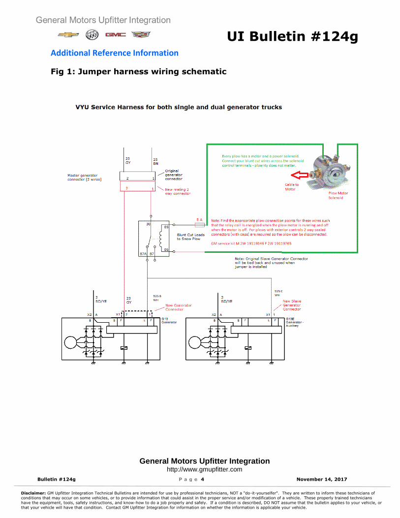
4) All systems final [signal] connection:
a) An operating signal must be identified to operate the small relay in the jumper harness. This signal
should go ON and OFF with the plow pump motor. The relay requires low power < 1 amp so most
any signal will do without loading issues. The schematic shows the control terminals on the motor
solenoid which is the most common connection point.
b) Using a test lamp try various connection points on the plow control wiring to identify a signal that
will illuminate the test lamp only when the motor is running.
Note:
Some plows will present hot [B+] to both motor solenoid control terminals until one side goes to
ground. As long as the lamp works right the jumper can be connected the same way. Connect the
blunt cut red and black wires across the same signal source as was used to operate the test lamp.
Normally the red wire will go to B+ and black to ground. [If both connection points are at B+ when
the motor is at rest then put the black wire to the side that goes to ground when the motor runs and
the red one to the constant B+ connection.]
c) See figure 4 if the operating signal must be obtained outside of the engine compartment [on the
plow itself]. An inline connector will be required. [See schematic for PNs.] 2 sets of connectors will
allow for capping when the plow is disconnected. Secure the wires and caps appropriately to
assure durability.
UI Bulletin #124g
General Motors Upfitter Integration http://www.gmupfitter.com
Bulletin #124g P a g e 4 November 14, 2017
Disclaimer: GM Upfitter Integration Technical Bulletins are intended for use by professional technicians, NOT a "do-it-yourselfer". They are written to inform these technicians of
conditions that may occur on some vehicles, or to provide information that could assist in the proper service and/or modification of a vehicle. These properly trained technicians
have the equipment, tools, safety instructions, and know-how to do a job properly and safely. If a condition is described, DO NOT assume that the bulletin applies to your vehicle, or
that your vehicle will have that condition. Contact GM Upfitter Integration for information on whether the information is applicable your vehicle.
Additional Reference Information
Fig 1: Jumper harness wiring schematic

UI Bulletin #124g
General Motors Upfitter Integration http://www.gmupfitter.com
Bulletin #124g P a g e 5 November 14, 2017
Disclaimer: GM Upfitter Integration Technical Bulletins are intended for use by professional technicians, NOT a "do-it-yourselfer". They are written to inform these technicians of
conditions that may occur on some vehicles, or to provide information that could assist in the proper service and/or modification of a vehicle. These properly trained technicians
have the equipment, tools, safety instructions, and know-how to do a job properly and safely. If a condition is described, DO NOT assume that the bulletin applies to your vehicle, or
that your vehicle will have that condition. Contact GM Upfitter Integration for information on whether the information is applicable your vehicle.
Fig: 2 Jumper Harness - Component Details

UI Bulletin #124g
General Motors Upfitter Integration http://www.gmupfitter.com
Bulletin #124g P a g e 6 November 14, 2017
Disclaimer: GM Upfitter Integration Technical Bulletins are intended for use by professional technicians, NOT a "do-it-yourselfer". They are written to inform these technicians of
conditions that may occur on some vehicles, or to provide information that could assist in the proper service and/or modification of a vehicle. These properly trained technicians
have the equipment, tools, safety instructions, and know-how to do a job properly and safely. If a condition is described, DO NOT assume that the bulletin applies to your vehicle, or
that your vehicle will have that condition. Contact GM Upfitter Integration for information on whether the information is applicable your vehicle.
Fig: 3 Jumper Harness Layouts [see detail 3 for updated relay mounting]

UI Bulletin #124g
General Motors Upfitter Integration http://www.gmupfitter.com
Bulletin #124g P a g e 7 November 14, 2017
Disclaimer: GM Upfitter Integration Technical Bulletins are intended for use by professional technicians, NOT a "do-it-yourselfer". They are written to inform these technicians of
conditions that may occur on some vehicles, or to provide information that could assist in the proper service and/or modification of a vehicle. These properly trained technicians
have the equipment, tools, safety instructions, and know-how to do a job properly and safely. If a condition is described, DO NOT assume that the bulletin applies to your vehicle, or
that your vehicle will have that condition. Contact GM Upfitter Integration for information on whether the information is applicable your vehicle.

UI Bulletin #124g
General Motors Upfitter Integration http://www.gmupfitter.com
Bulletin #124g P a g e 8 November 14, 2017
Disclaimer: GM Upfitter Integration Technical Bulletins are intended for use by professional technicians, NOT a "do-it-yourselfer". They are written to inform these technicians of
conditions that may occur on some vehicles, or to provide information that could assist in the proper service and/or modification of a vehicle. These properly trained technicians
have the equipment, tools, safety instructions, and know-how to do a job properly and safely. If a condition is described, DO NOT assume that the bulletin applies to your vehicle, or
that your vehicle will have that condition. Contact GM Upfitter Integration for information on whether the information is applicable your vehicle.
Layout Details
1. Primary Alternator
2. Slave Alternator
3. Relay Center and [new] corner brace
4. Wires to plow [fused + & ground]

UI Bulletin #124g
General Motors Upfitter Integration http://www.gmupfitter.com
Bulletin #124g P a g e 9 November 14, 2017
Disclaimer: GM Upfitter Integration Technical Bulletins are intended for use by professional technicians, NOT a "do-it-yourselfer". They are written to inform these technicians of
conditions that may occur on some vehicles, or to provide information that could assist in the proper service and/or modification of a vehicle. These properly trained technicians
have the equipment, tools, safety instructions, and know-how to do a job properly and safely. If a condition is described, DO NOT assume that the bulletin applies to your vehicle, or
that your vehicle will have that condition. Contact GM Upfitter Integration for information on whether the information is applicable your vehicle.
Detail 1

UI Bulletin #124g
General Motors Upfitter Integration http://www.gmupfitter.com
Bulletin #124g P a g e 10 November 14, 2017
Disclaimer: GM Upfitter Integration Technical Bulletins are intended for use by professional technicians, NOT a "do-it-yourselfer". They are written to inform these technicians of
conditions that may occur on some vehicles, or to provide information that could assist in the proper service and/or modification of a vehicle. These properly trained technicians
have the equipment, tools, safety instructions, and know-how to do a job properly and safely. If a condition is described, DO NOT assume that the bulletin applies to your vehicle, or
that your vehicle will have that condition. Contact GM Upfitter Integration for information on whether the information is applicable your vehicle.
Detail 2

UI Bulletin #124g
General Motors Upfitter Integration http://www.gmupfitter.com
Bulletin #124g P a g e 11 November 14, 2017
Disclaimer: GM Upfitter Integration Technical Bulletins are intended for use by professional technicians, NOT a "do-it-yourselfer". They are written to inform these technicians of
conditions that may occur on some vehicles, or to provide information that could assist in the proper service and/or modification of a vehicle. These properly trained technicians
have the equipment, tools, safety instructions, and know-how to do a job properly and safely. If a condition is described, DO NOT assume that the bulletin applies to your vehicle, or
that your vehicle will have that condition. Contact GM Upfitter Integration for information on whether the information is applicable your vehicle.
Detail 3.1.1
Details 3.1.1-3 apply to service part and not the factory included [loose shipped] part.
See Details 3.2.1-7 for the later version factory harness that comes with a new truck.
Add tie straps to relay

UI Bulletin #124g
General Motors Upfitter Integration http://www.gmupfitter.com
Bulletin #124g P a g e 12 November 14, 2017
Disclaimer: GM Upfitter Integration Technical Bulletins are intended for use by professional technicians, NOT a "do-it-yourselfer". They are written to inform these technicians of
conditions that may occur on some vehicles, or to provide information that could assist in the proper service and/or modification of a vehicle. These properly trained technicians
have the equipment, tools, safety instructions, and know-how to do a job properly and safely. If a condition is described, DO NOT assume that the bulletin applies to your vehicle, or
that your vehicle will have that condition. Contact GM Upfitter Integration for information on whether the information is applicable your vehicle.
Detail 3.1.2
Single Battery Trucks

UI Bulletin #124g
General Motors Upfitter Integration http://www.gmupfitter.com
Bulletin #124g P a g e 13 November 14, 2017
Disclaimer: GM Upfitter Integration Technical Bulletins are intended for use by professional technicians, NOT a "do-it-yourselfer". They are written to inform these technicians of
conditions that may occur on some vehicles, or to provide information that could assist in the proper service and/or modification of a vehicle. These properly trained technicians
have the equipment, tools, safety instructions, and know-how to do a job properly and safely. If a condition is described, DO NOT assume that the bulletin applies to your vehicle, or
that your vehicle will have that condition. Contact GM Upfitter Integration for information on whether the information is applicable your vehicle.
Detail 3.1.3
Dual Battery Trucks
UI Bulletin #124g
General Motors Upfitter Integration http://www.gmupfitter.com
Bulletin #124g P a g e 14 November 14, 2017
Disclaimer: GM Upfitter Integration Technical Bulletins are intended for use by professional technicians, NOT a "do-it-yourselfer". They are written to inform these technicians of
conditions that may occur on some vehicles, or to provide information that could assist in the proper service and/or modification of a vehicle. These properly trained technicians
have the equipment, tools, safety instructions, and know-how to do a job properly and safely. If a condition is described, DO NOT assume that the bulletin applies to your vehicle, or
that your vehicle will have that condition. Contact GM Upfitter Integration for information on whether the information is applicable your vehicle.
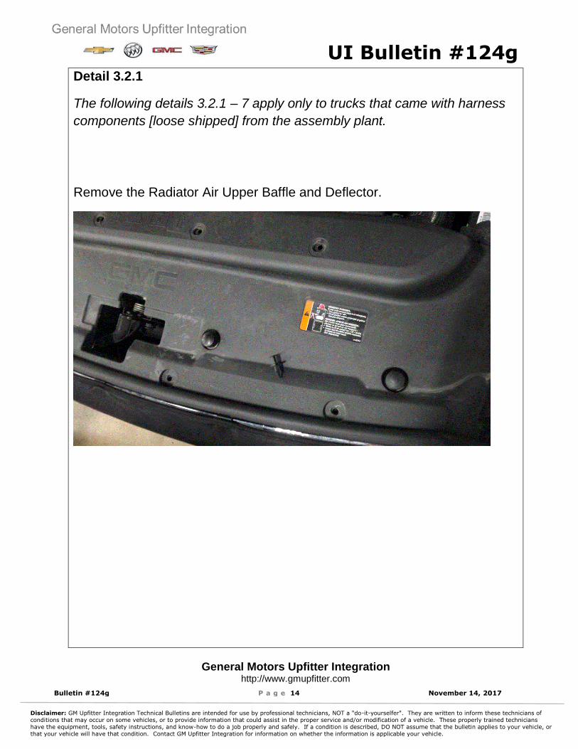
Detail 3.2.1
The following details 3.2.1 – 7 apply only to trucks that came with harness
components [loose shipped] from the assembly plant.
Remove the Radiator Air Upper Baffle and Deflector.

UI Bulletin #124g
General Motors Upfitter Integration http://www.gmupfitter.com
Bulletin #124g P a g e 15 November 14, 2017
Disclaimer: GM Upfitter Integration Technical Bulletins are intended for use by professional technicians, NOT a "do-it-yourselfer". They are written to inform these technicians of
conditions that may occur on some vehicles, or to provide information that could assist in the proper service and/or modification of a vehicle. These properly trained technicians
have the equipment, tools, safety instructions, and know-how to do a job properly and safely. If a condition is described, DO NOT assume that the bulletin applies to your vehicle, or
that your vehicle will have that condition. Contact GM Upfitter Integration for information on whether the information is applicable your vehicle.
Detail 3.2.2
Identify the new flat painted corner brace pn 84234282. [unpainted version
shown]

UI Bulletin #124g
General Motors Upfitter Integration http://www.gmupfitter.com
Bulletin #124g P a g e 16 November 14, 2017
Disclaimer: GM Upfitter Integration Technical Bulletins are intended for use by professional technicians, NOT a "do-it-yourselfer". They are written to inform these technicians of
conditions that may occur on some vehicles, or to provide information that could assist in the proper service and/or modification of a vehicle. These properly trained technicians
have the equipment, tools, safety instructions, and know-how to do a job properly and safely. If a condition is described, DO NOT assume that the bulletin applies to your vehicle, or
that your vehicle will have that condition. Contact GM Upfitter Integration for information on whether the information is applicable your vehicle.
Detail 3.2.3
Relay center and bracket details.

UI Bulletin #124g
General Motors Upfitter Integration http://www.gmupfitter.com
Bulletin #124g P a g e 17 November 14, 2017
Disclaimer: GM Upfitter Integration Technical Bulletins are intended for use by professional technicians, NOT a "do-it-yourselfer". They are written to inform these technicians of
conditions that may occur on some vehicles, or to provide information that could assist in the proper service and/or modification of a vehicle. These properly trained technicians
have the equipment, tools, safety instructions, and know-how to do a job properly and safely. If a condition is described, DO NOT assume that the bulletin applies to your vehicle, or
that your vehicle will have that condition. Contact GM Upfitter Integration for information on whether the information is applicable your vehicle.
Detail 3.2.4
Remove the [round] left front corner brace shown here.

UI Bulletin #124g
General Motors Upfitter Integration http://www.gmupfitter.com
Bulletin #124g P a g e 18 November 14, 2017
Disclaimer: GM Upfitter Integration Technical Bulletins are intended for use by professional technicians, NOT a "do-it-yourselfer". They are written to inform these technicians of
conditions that may occur on some vehicles, or to provide information that could assist in the proper service and/or modification of a vehicle. These properly trained technicians
have the equipment, tools, safety instructions, and know-how to do a job properly and safely. If a condition is described, DO NOT assume that the bulletin applies to your vehicle, or
that your vehicle will have that condition. Contact GM Upfitter Integration for information on whether the information is applicable your vehicle.
Detail 3.2.5
Assemble the relay bracket to the flat corner brace using hardware
provided. Snap the relay bracket into the feature on the relay center.
UI Bulletin #124g
General Motors Upfitter Integration http://www.gmupfitter.com
Bulletin #124g P a g e 19 November 14, 2017
Disclaimer: GM Upfitter Integration Technical Bulletins are intended for use by professional technicians, NOT a "do-it-yourselfer". They are written to inform these technicians of
conditions that may occur on some vehicles, or to provide information that could assist in the proper service and/or modification of a vehicle. These properly trained technicians
have the equipment, tools, safety instructions, and know-how to do a job properly and safely. If a condition is described, DO NOT assume that the bulletin applies to your vehicle, or
that your vehicle will have that condition. Contact GM Upfitter Integration for information on whether the information is applicable your vehicle.
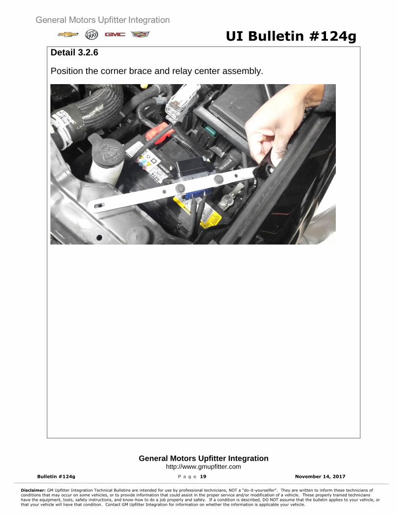
Detail 3.2.6
Position the corner brace and relay center assembly.

UI Bulletin #124g
General Motors Upfitter Integration http://www.gmupfitter.com
Bulletin #124g P a g e 20 November 14, 2017
Disclaimer: GM Upfitter Integration Technical Bulletins are intended for use by professional technicians, NOT a "do-it-yourselfer". They are written to inform these technicians of
conditions that may occur on some vehicles, or to provide information that could assist in the proper service and/or modification of a vehicle. These properly trained technicians
have the equipment, tools, safety instructions, and know-how to do a job properly and safely. If a condition is described, DO NOT assume that the bulletin applies to your vehicle, or
that your vehicle will have that condition. Contact GM Upfitter Integration for information on whether the information is applicable your vehicle.
Detail 3.2.7
Mount the flat corner brace assembly as shown.

UI Bulletin #124g
General Motors Upfitter Integration http://www.gmupfitter.com
Bulletin #124g P a g e 21 November 14, 2017
Disclaimer: GM Upfitter Integration Technical Bulletins are intended for use by professional technicians, NOT a "do-it-yourselfer". They are written to inform these technicians of
conditions that may occur on some vehicles, or to provide information that could assist in the proper service and/or modification of a vehicle. These properly trained technicians
have the equipment, tools, safety instructions, and know-how to do a job properly and safely. If a condition is described, DO NOT assume that the bulletin applies to your vehicle, or
that your vehicle will have that condition. Contact GM Upfitter Integration for information on whether the information is applicable your vehicle.
Detail 4
On units were the control signal must be obtained out on the plow wiring. A 2-way
sealed connector will be required as shown here. See schematic for PNs.

UI Bulletin #131
General Motors Upfitter Integration http://www.gmupfitter.com
Bulletin #131 P a g e | 1 June 01, 2016
Disclaimer: GM Upfitter Integration Technical Bulletins are intended for use by professional technicians, NOT a "do-it-yourselfer". They are written to inform these technicians of
conditions that may occur on some vehicles, or to provide information that could assist in the proper service and/or modification of a vehicle. These properly trained technicians
have the equipment, tools, safety instructions, and know-how to do a job properly and safely. If a condition is described, DO NOT assume that the bulletin applies to your vehicle, or
that your vehicle will have that condition. Contact GM Upfitter Integration for information on whether the information is applicable your vehicle.
Subject: Elevated Engine Coolant/OperatingTemperatures with Snow Plow Mounted
Models Years
Affected: 2014 and beyond
Models Affected:
Chevrolet Silverado Regular Cab 1500 GMC Sierra Regular Cab 1500
Origination Date:
June 1, 2016
Revision Date:
N/A
ADVISORY:
Condition/Concern: Some customers may express concern about one or both of the following when a snow plow is attached to the front of the trucks:
1. Higher than normal engine or transmission temperature.2. Incorrect outside temperature reading.
Both of the above conditions can occur due to the reduced airflow into the radiator area with the plow in the raised position. The air flow is diverted upward as a result of the raised plow and thereby does not enter the front grille area of the vehicle.
Repair/Recommendation: In many situations, the following steps may improve air flow to the front of vehicle/grill area to improve cooling and/or reduce operating temperatures:
Try lowering or repositioning (angling) of the plow.
If repositioning attempts are unsuccessful in reducing the operation temperature, GMrecommends that an air foil be added to the top of the plow, similar to the one shown below.
Note: Per vehicle Owner Manual “Caution: Do not exceed 64 km/h (40 mph) with a snow plow mounted to the vehicle. The vehicle could overheat and be damaged.”

UI Bulletin 116b
General Motors Upfitter Integration http://www.gmupfitter.com
Bulletin 116b P a g e | 1 December 6, 2016
Disclaimer: GM Upfitter Integration Technical Bulletins are intended for use by professional technicians, NOT a "do-it-yourselfer". They are written to inform these technicians of conditions that may occur on some vehicles, or to provide information that could assist in the proper service and/or modification of a vehicle. These properly trained technicians have the equipment, tools, safety instructions, and know-how to do a job properly and safely. If a condition is described, DO NOT assume that the bulletin applies to your vehicle, or
that your vehicle will have that condition. Contact GM Upfitter Integration for information on whether the information is applicable your vehicle.
Subject: Snow Plow Lamp Activation
Models Years Affected:
2014 and Beyond
Models Affected:
Chevrolet Silverado GMC Sierra
Origination Date:
June 9, 2014
Revision Date:
December 6, 2016
ADVISORY:Condition/Concern: Upfitters installing Snow Plows have requested additional information regarding the vehicle headlamp interface and the system function/requirements when the headlamps are switched from truck headlamps to plow mounted headlamps. Some customers have reported that one or both headlamps go off when attaching the plow and switching over to the plow lamps.
Repair/Recommendation: For best results, switch lights to Park or OFF before connecting the electrical plugs when mounting the plow. This avoids current surges that could cause headlamp low beam shut down. Once the plow lights are connected the headlamps may be turned back ON.
Additional Information: The plots below show the expected ‘actual’ headlamp current vs the ‘over current’ limits at
headlamp activation. The BCM expects to see a a single ‘high current inrush and decay event’
[current spike] as is normal with both incandescent and HID headlamps. If the headlamp circuit
is switched [disconnected and then reconnected] after initial turn ON the subsequent [later]
current spike may cause the diagnostic to turn the lamp off. Each time the headlamp is turned
ON the diagnostic runs and a single current spike occurs. However, once normal running current
is reached if a [later] second current spike occurs the BCM may turn off the lamp to protect the
driver chip. Switching or interrupting the headlamp circuit causes current spikes. High current is
not expected after lamp warm up and ‘looks like’ a short circuit.
Later version trucks have limited ‘retry’ provisions in the headlamp lamp diagnostic which
renders the system somewhat tolerant to a ‘switch over’ event. [It will try a few times before
shutting down.] Turning headlamps OFF at plow connection is best.

UI Bulletin 116b
General Motors Upfitter Integration http://www.gmupfitter.com
Bulletin 116b P a g e | 2 December 6, 2016
Disclaimer: GM Upfitter Integration Technical Bulletins are intended for use by professional technicians, NOT a "do-it-yourselfer". They are written to inform these technicians of conditions that may occur on some vehicles, or to provide information that could assist in the proper service and/or modification of a vehicle. These properly trained technicians have the equipment, tools, safety instructions, and know-how to do a job properly and safely. If a condition is described, DO NOT assume that the bulletin applies to your vehicle, or
that your vehicle will have that condition. Contact GM Upfitter Integration for information on whether the information is applicable your vehicle.
Figure 1: Over-current Plot 2014 - 2016

UI Bulletin 116b
General Motors Upfitter Integration http://www.gmupfitter.com
Bulletin 116b P a g e | 3 December 6, 2016
Disclaimer: GM Upfitter Integration Technical Bulletins are intended for use by professional technicians, NOT a "do-it-yourselfer". They are written to inform these technicians of conditions that may occur on some vehicles, or to provide information that could assist in the proper service and/or modification of a vehicle. These properly trained technicians have the equipment, tools, safety instructions, and know-how to do a job properly and safely. If a condition is described, DO NOT assume that the bulletin applies to your vehicle, or
that your vehicle will have that condition. Contact GM Upfitter Integration for information on whether the information is applicable your vehicle.
Figure 2: Over-current Plot 2017 and later [incandescent and HID]
X400
X
410
X90
0