table of contents - kogan.comalarm linkage: triggered record, linkage alarm output and linkage ptz...
TRANSCRIPT


Table of ContentsChapter One: Product Introduction......................................................................................................2
1 Brief Introduction.........................................................................................................................22 Main Features...............................................................................................................................2
Chapter Two: Hardware........................................................................................................................31 Package Content...........................................................................................................................32 Front Panel Operation...................................................................................................................33 Rear Panel of Operation................................................................................................................34 Remote Controller.........................................................................................................................35 Hard Disk Installation...................................................................................................................46 Rear Panel Connection..................................................................................................................4
Chapter Three: Usage...........................................................................................................................61 Brief Introduction.........................................................................................................................62 Menu Operations...........................................................................................................................7
Chapter Four: Operations.....................................................................................................................81 Turn on..........................................................................................................................................82 Preview.........................................................................................................................................83 Record.........................................................................................................................................104 Camera Control...........................................................................................................................115 Motion Detection Settings..........................................................................................................126 Mask Setting...............................................................................................................................137 Playback......................................................................................................................................138 Backup........................................................................................................................................149 Alarm Settings.............................................................................................................................1410 Network Operation...................................................................................................................1511 Maintenance..............................................................................................................................1812 Advanced Settings.....................................................................................................................20
Chapter Five: Appendix......................................................................................................................221 Specifications.......................................................................................................................................................222 Methods of Calculating HDD Capacity......................................................................................243 Default Values.............................................................................................................................254 Introduction of Mobile Phone Monitoring..................................................................................27
1

Chapter One: Product Introduction
1 Brief Introduction
This series DVR is a 4-channel playback H.264 main profile standalone DVR with Pentaplex functionality: record, playback, live preview, remote preview and backup supported.With professional and high performance intelligent audio and video solutions, user-friendly GUI and practical industrial design, this series DVR is suitable for civil applications such as home, store, internet bars and small offices as well as for common security and surveillance applications.
2 Main Features
• Compression4/8 channel PAL/NTSC/SECAM video input and H.264 compression standards with each channel being compressed independently in real-time CIF resolution, or non-real time D1,2CIF resolution.4 channel audio input and G.726/ADPCM-IMA compression standards with each channel being compressed independently in 24Kbps.Compressed video and audio are synchronous. You can select either mixed streams or individual video streams.Four-level record quality and self-defined bit rate and frame rate settings supported.Adjustable video parameters.Multi-area motion detection.OSD of channel name and time supported.
• RecordingManual record and schedule record supported. The schedule report types include: timing, motion detection, alarm, motion detection | alarm.SATA hard-disk supported.Backup and clip record files through USB drive, portable USB HDD and USB CD/DVD RW supported.
• Preview and PlaybackSimultaneous output of VGA and TV.Up to 4 channels playback in fast play mode, slow play mode, rewind and single frame forward supported.OSD of channel name and time supported.Status displaying of local record, alarm and motion detection supported.
• ControlControlling of PTZ and dome supported.Controlling multiple DVRs with on RS485 keyboard.Setting and calling preset, sequence and track supported.
• AlarmLocal alarm (includes exception and motion detection, video loss and hard disk full) triggered handling supported.Alarm linkage: triggered record, linkage alarm output and linkage PTZ preset, sound alarm, report to alarm center, linkage channel single screen display and e-mail.
• NetworkTCP/IP supported.PPPoE supported.Dynamic access to IP address, Dynamic Host Configuration Protocol (DHCP) supported.DDNS supported.Visit video files in DVR HDD through network neighbourhood supported.Controlling of PTZ, configuring device parameters, acquiring device status and logs, and upgrade remotely through network supported.Local recording through network supported.
2

Chapter Two: Hardware
This chapter is a general description of the device interfaces and connections. It describes the methods of hard disk installation, the interface of the front panel and the rear panel for users to connect the cables correctly.
1 Package Content
After purchasing the DVR product, unpack it and unload it flat onto the floor or a place where it is to be located, and refer to the “Package Contents” for the correct number of device fittings.
2 Front Panel Operation
Table 1 – Front Panel Description
Type Name Description
LEDPower Red when recording. Green when not recording.
HDD Hard disk indicator. Green or blinking when reading/writing.Black when idle.
3 Rear Panel of Operation
Table 2 – Rear Panel Description
NO. Interface Description
1 Video In 4/8 channel video input: BNC (1Vp_p, 75Ω)
2 TV Out 1 channel TV output, BNC (1Vp-p, 75Ω)
3 Audio Out 1 channel audio output, BNC (2Vp-p, 600Ω)
4 Audio In 4 channels audio input: RCA (2Vp-p, 600Ω)
5 VGA Output 1: DIN-15
6Network Interface 1: RJ45 10/100M self-adaptive
USB Interface 2: USB 2.0
7 RS485 1: Half Duplex ( + - )
8 Power DC 12V
4 Remote Controller
Table 3 – Remote Controller Description
NO. Name Description
1 REC Record
2 Power ON/OFF Turn the device off or on.
3 Numbers Input numbers or select to switch among relevant channels.
4 Function Buttons DEL: Delete
5 Arrow Buttons When in menu mode, press [◄ ], [► ] to move to selection boxes. Press [▲ ], [▼ ] to select sub-menu parameters.
6 1) Press to confirm operations in menu mode.2) Press to select record type in setting schedule.3) Press to change status of the current motion detection block.
3
7 Switch between single screen and multi-screen.
8 FN 1) Press to switch from single split to multi-split view mode, or reverse in preview and playback mode.2) Press to enter/exit continuous selection when setting motion detection area and schedule record.3) Press to set start time and end time in file search.
9 MENU One key system setup.
10 ESC Return to previous menu.
11 PTZ One key PTZ control.
12 BACKUP Backup Record
13 TV/VGA Switch the operation interface between TV and VGA.
14 CLEAR Alarm Off
15 SEQ Call Sequence
16 1) Play/Pause2) One key file search
17 Stop
18 Play in slow mode/fast rewind
19 Fast forward
5 Hard Disk Installation
The hard disk is not included in the factory fittings. Users can mount suitable hard disks by calculating its capacity referring “Appendix 5.2 Methods of Calculating HDD Capacity”.
1) Installation procedure• Open the DVR case. Mount the 4 shock absorption washers into the clamping slots (four protruding
steps) in the case.• Connect the HDD data cable and HDD power cable to the HDD.• Attach the hard disk to the shock absorption washers by aligning the installation holes to the case.
Hold and fix them by 4 x M3*12 head screws plus plain washers.• Connect the HDD data cable and HDD power cable to the respond interfaces of the main board.• Replace the DVR top cover, then screw it closed.
NOTE: If installing your own HDD, please be sure to purchase a DVR rated HDD instead of a computer ratedHDD. Computer rated HDDs are not designed for continuous DVR use.NOTE: Please format the HDD for the first use, or the system will return a “Hard Disk Error” notification accompanied by an audio alarm. Please see 4.9 Maintenance for details.
6 Rear Panel Connection
• Power InputConnect the power adapter to the Power Input interface of the DVR. Confirm that the DVR power supply input switch is positioned correctly for the local voltage before connecting and powering the unit.Turn on the unit. The power LED will light up if the power cable is connected correctly.NOTE: Please use the power adapter contained in the package.
• Video InputThe video input interface is standard BNC socket, 1Vp-p, 75Ω.NOTE: The video signal cable should be kept away from the interference of strong electromagnetism and thecity electric power grid.
4
• Audio InputThe audio input interface standard RAC socket, 2Vp-p, 600Ω.NOTE: The audio input resistance is a little high, please use an active sound collection device or active microphone. The audio signal cable should be kept away from the interference of strong electromagnetism and the city electric power grid.
• Network InputThe network input interface is RJ45 10/100M self-adaptive.NOTE: Confirm that the network band width is enough for transmitting high definite images smoothly.
• Alarm Input and OutputThe alarm input device should be the type of GND connected alarm or voltage input alarm, which can be set as N/O, or N/C.The requirement of signal input level for voltage alarm type is: low level 0~2V, high level 5~15V.The green angle pins of the signal cable are designed for access of PTZ and alarming devices. Please follow these steps to connect.
1. Pull out the angle pins that are inserted in the alarm input and output interfaces.2. Unscrew the screws with a micro Philips screwdriver, insert the signal cable into the interface under
the spring, then tighten the screws.3. Plug the connected pins into the green angle pin socket.
• PTZ Input (Pan-Tilt-Zoom)Connect the PTZ control interface to the RS485 interfaces of the rear panel. The connection method is similar to the method above.NOTE: Please refer to the PTZ manual for setting specific parameters, for some PTZ devices contain multiple telecommunication protocols, baud rates and IDs.Video Output: VGA/Monitor InputVideo output interface: TV and VGA, which can work together simultaneously.NOTE: VGA and TV cannot be in the operation interface simultaneously, but can be switched by mouse, panel or remote control in the menu.
5

Chapter Three: Usage
1 Brief Introduction
6
2 Menu Operations
Press [SET] button to enter into system setting screen.Press [●] button to start/stop recording manually.Press [► ▋▋ ] button to play the recorded file.Press [PTZ] to enter into the PTZ control screen.NOTE: This manual indicates the menu selection icons and selection boxes in [XX]; the buttons in the menu screen (except menu selection icons) in [XX]; the buttons on the front panel and remote controller in [XX].The highlight menu is the current active one. The user can move the highlight icon on the menu by using the[►], [◄], [▲] and [▼] buttons, and press the [OK] button to confirm the selection, or press [ESC] to return to the upper menu.Selection Box: User can move the highlight icon in the selection box by using the [◄] and [►] button, and press [OK] to confirm the selection. Multiple items are allowed to be selected together at once by left clickingthe mouse.Sub menu list: User can move the highlight icon to the sub menu required by using the [◄] and [►] button, or roll the mouse to select directly. Only one item can be selected here.Edition Box: When in edition box, user can type in numbers directly by pressing the number buttons. Press [DEL] to delete the character before the cursor and press [OK] or [ESC] button to exit.Sub screen button: Press it to pop up the sub screen. When in sub screen, select [CONFIRM] to save the configuration and return to the upper menu. Press [ESC] or select [CANCEL] to return to the upper menu without being saved.Use [◄], [►] to move the highlight icon to any of the selection boxes. Press [OK] button to switch to anotherselect status. User [▲], [▼] to specify the sub menu value where sub menu selections exist.Exit: User can click the button on the upper right corner, or single right click the mouse, or press [ESC] button to enter into the Save & Exit screen. You can select exit directly or exit after being saved.NOTE: There are two different ways to take effect: take effect instantly or take effect after being saved. Please refer to the navigation for details.
7

Chapter Four: Operations
This chapter mainly describes the main system operations of the DVR. Please refer to the following contentsfor details.
1 Turn on
Start UpThe power LED will be lit up after powering on correctly. Please refer to 2.6 Rear Panel Connection for details of connection method. Press [Power on/off] to start up the device. The preview screen will appear. After pressing the [ESC] button of the panel or remote, or right clicking the mouse, the login box will appear. Please select the proper user and type in the relevant password to log in.NOTE: It takes about 60 seconds for the unit to start up. Please be patient.NOTE: Modify the password by selecting <Tool Bar>→<System>→<System Setting>→<Password Setting>. Set as indicated and the new password will take effect instantly.NOTE: Default password for Admin is 111111. Default password for User is 111111. Admin password can be restored to factory defaults by short-circuit “JP 1” on the main-board. After logging in by Admin, the Admin can change the user's password. The system supports 8 users, and the Admin is the manager user with all permissions, whose name cannot be deleted or changed. The Admin user can add and delete all other users and permissions.NOTE: The DVR will buzz and “NO Hard Disk” appears when running without a hard disk. User can choose whether to buzz or not when using without a hard disk.NOTE: The DVR can identify the display device automatically. When connected either to VGA or TV, the menu will be on the specified screen automatically after start-up. When connecting VGA and TV simultaneously, two images will be displayed on the screen, with it defaulting to VGA first. User can switch by clicking in the tool bar.
SYSTEM SETTINGSLanguage: Please enter <Tool Bar>→<System>→<System Setting>→<Language> to set the language.VGA Resolution: Please enter <Tool Bar>→<System>→<System Setting>→<VGA Resolution> to set the VGA resolution and refresh rate. It supports 800x600@60Hz, 1024x768@60Hz, 1280x1024@60Hz, 1440x900@60Hz currently. Please select relevant values according to the parameters of your setup.Time Format: Please enter <Tool Bar>→<System>→<System Setting>→<Time Format> to set the time format. 12 hour and 24 hour formats are supported. Date/Time: Please enter <Tool Bar>→<System>→<System Setting>→<Time Setting> to set the date and time.Video Standard: Please enter <Tool Bar>→<System>→<System Setting>→<Video Standard> to set the video standard. PAL, SECAM and NTSC are supported. Please set according to the parameters of the camera.NOTE: Please make sure the HDD is not recording when you set the system time, as it can cause an error when playing back recorded video.NOTE: “Language” and “Time” will take effect immediately. “Record Resolution” and “Video Standard” will only take effect after being saved.NOTE: When the resolution setting exceeds the range of the display, please click [ESC][2][ESC] on the FrontPanel or remote controller within 3 seconds to reduce the resolution to [email protected]: Users can refer to the navigations on the bottom of the main screen to look for relevant guides. Meanwhile, navigation info will display “Take effect instantly” / “Take effect after being saved”.
2 Preview
After starting up the system, the screen has a live view area and a tool bar. Right-click the mouse in preview mode or press [OK] on the front panel, and the tool bar will appear. The system status column can be dragged anywhere on the screen by mouse, and will be back in the default position next time the device isrestarted. The column can be hidden by right-clicking the mouse.Videos, OSD of channel name, record time and alarm notifications will be displayed on screen.
8
1) Channel Status Display AreaUnder preview mode, channel shows current input image and channel status information (video status and mode, motion detection)
View Mode SwitchingWhen in 1/4/6/8/9/16 splits view mode, the tile with the highlighted green border is the currently selected one.The user can use the mouse or press the direction buttons to switch to another tile. If the audio output device is connected, the audio can be previewed together with video. The audio of the current channel can be previewed besides in playback mode.Users can select to display a particular channel by pressing the number buttons.When in preview mode, user can enter into 1/4/6/8/9/16 splits view mode by pressing the button directly, or vice versa.NOTE: For 8 channel DVR, the view mode can be directly switched by tool bar. Please refer to 4.2.3 “Tool Bar”.
Image Parameters SettingPlease enter <Tool Bar>→<System>→<Video>→<Colour Setting> to set brightness, contrast, hue and saturation. It will take effect instantly.NOTE: User can set image parameters of one channel one at a time, or for all channels at once by selecting [ALL] in <Camera Channel>. It is similar to other screens when the user wants to set four channels together at once: select [ALL] in <Channel>.NOTE: In preview mode, brightness and contrast can be adjusted by the remote controller directly.
OSD SettingsThe OSD of channel name and system time is supported. Please enter <Tool Bar>→<System>→<Record Setting>→<OSD Setting> to set. The channel name will be displayed on the left upper corner, and the channel time will be displayed on the right corner of the screen.
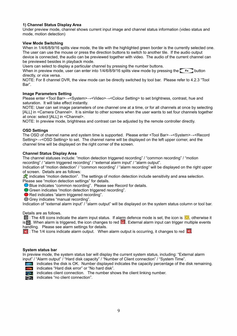
Channel Status Display AreaThe channel statuses include: “motion detection triggered recording” / “common recording” / “motion recording” / “alarm triggered recording” / “external alarm input” / “alarm output”.Indication of “motion detection” / “common recording” / “alarm recording” will be displayed on the right upper of screen. Details are as follows: indicates “motion detection”. The settings of motion detection include sensitivity and area selection. Please see “motion detection settings” for details. Blue indicates “common recording”. Please see Record for details. Green indicates “motion detection triggered recording”. Red indicates “alarm triggered recording”. Grey indicates “manual recording”.Indication of “external alarm input” / “alarm output” will be displayed on the system status column or tool bar.
Details are as follows. : The 4/8 icons indicate the alarm input status. If alarm defence mode is set, the icon is , otherwise it is . When alarm is triggered, the icon changes to red . External alarm input can trigger multiple events handling. Please see alarm settings for details. : The 1/4 icons indicate alarm output. When alarm output is occurring, it changes to red .
System status barIn preview mode, the system status bar will display the current system status, including: “External alarm input” / “Alarm output” / “Hard disk capacity” / “Number of Client connection” / “System Time”.
indicates the disk is OK. Number displayed indicates the capacity percentage of the disk remaining.indicates “Hard disk error” or “No hard disk”.indicates client connection. The number shows the client linking number.indicates “no client connection”.
9

Tool BarRight click the mouse or press [OK] in preview mode to show the Tool Bar, as shown below.
Fig IV: System Toolbar
: Hide the tool bar. : System configuration. Please see 3.1 Menu Structure for details. : Manual record. Please see 4.3.1 Manual Record for details. : Search, playback and backup record files. Please see 4.5 Video Playback and 4.6 Video Backup for details. : PTZ operation. Please see 4.4.1 PTZ Control for details. : Click to cancel alarm notification. Click this button for a pop-up of the present alarm information. : Fast playback. User can enter 10, 20, 30 or 60 seconds before position start playback, and can also jump to a specified time in the video. : Power off. Clicking this button will pop up a “confirm password” message. User has to enter the Admin password to shut down. , , , , , : Set the preview mode of “Single splits view”, “4 splits view”, “6 splits view”, “8 splits view”, “9 splits view” and “16 splits view”. : Fast switch TV and VGA. Menu will not be available on the current screen, only a preview image. : To adjust the screen, 8 pixels per unit. , : To reduce or increase screen vertically. , : To reduce or increase screen horizontally. : To move the screen up, down, left or right. : To zoom out the screen to maximum and show in the central position.NOTE: When the mouse moves to the tool bar icon, the indication information will appear to help give the user guidance.NOTE: When the video source is PAL, the screen display range max is 720x576. When the video source is NTSC, the screen display range max is 720x480.NOTE: Switch display menu between VGA and TV by selecting [ESC]→[1]→[ESC] (sequence must be pressed within 3 seconds) on the remote control or front panel.
3 Record
Record type contains manual record and schedule record. The priority of manual record is higher than schedule. If the record schedule is conflicted with the manual recording, the manual recording will be recognised and processed until the manual recording is cancelled.Record types include “common recording” / “alarm triggered recording” / “motion detection triggered recording” / “alarm / motion detection triggered recording”. Each is indicated with a grid of a different colour, and each colour indicates a particular recording status. Please see Fig IV-2 Record Schedule for details.
Record resolution: The device supports “CIF” / “HALF D1” / “D1” formats.Record quality: “Best 768Kbps” / “High 640Kbps” / “Better 512Kbps” / “Common 384Kbps”.Record frame rate: If the current selection is PAL, the frame rate options are “All” / “12” / “6” / “3” / “1” / “Customised”. If the current selection is NTSC, the frame rate options are “All” / “15” / “7” / “3” / “1” / Customised”. Default is “All” which is 25fps for PAL and 30fps for NTSC.Record resource: “Video” for video only, or “Video and Audio” for recording video and audio.NOTE: Please refer to Appendix 6.2 for the methods of calculating HDD capacity.
Manual RecordPlease enter <Tool Bar>→<Manual Record> to let the specific channel record.Press the [●] button to start/stop recording manually.NOTE: The type of the video recorded manually is known as “common recording”.NOTE: The highest priority of recording is manual recording.
Record SchedulePlease enter <Tool Bar>→<System>→<Record Setting> to set the record schedule. The setting screen is shown as the figure overleaf.
10

Fig IV-2 Record Schedule
The current recording schedule➀ The record schedule➁ Description of record type➂
Users are free to select a week day or the day of a period of time. The system provides a recording option for hours every day, or a week day. Each unit (measured by a grid square) indicates one hour.
Move highlight icon to a time grid using the [Direction] buttons.➀ Specify the recording type by repeatedly pressing [OK] button or double left clicking the mouse. ➁
(The colour of the grid will change accordingly.) Select [OK] to confirm settings. The settings will take effect after being saved.➂
NOTE: Users can copy the current setting onto a neighbouring grid by pressing [Fn] button first, [Direction] buttons secondly, and then the [Fn] button again to exit. Alternately, user can drag the mouse to set.NOTE: When motion detection recording is selected, the motion detection sensitivity and area should be set ahead of time. Please refer to 4.4.2 Motion Detection settings for details. When alarm recording is selected, the alarm triggering settings should be set ahead. Please refer to 4.7.2 Event Handling for details.
4 Camera Control
PTZ ControlEnter <Tool Bar>→<System>→<Video> to set camera channel, protocol, baud rate and ID.NOTE: The different PTZ controlled by one PCI should have corresponding PTZ IDs. There are 256 PTZ IDssupported currently, 0~255.
PTZ OperationsIn preview mode, select a tile first (in 4/9/16 splits view mode, the selected tile is with the highlighted green border), using mouse or [Numbers] buttons, and then enter <Tool Bar>→<PTZ Control> to the PTZ Control screen that is shown as the table below.
Table IV 1 PTZ Operation Description
11
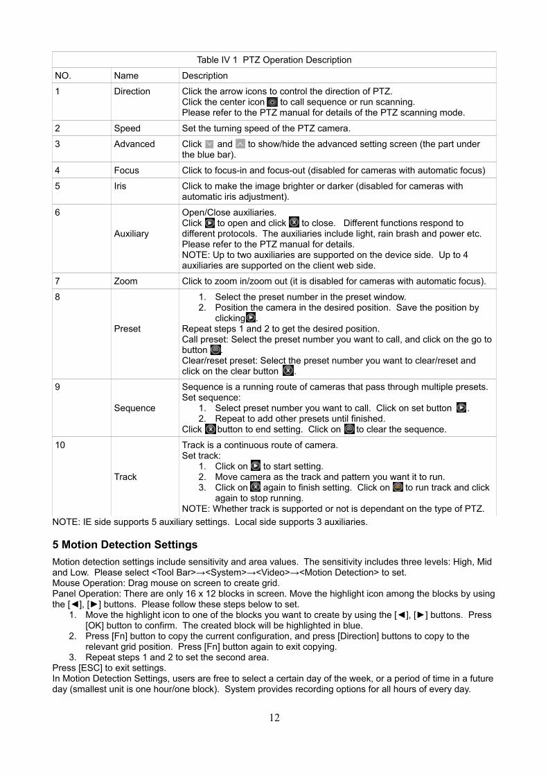
Table IV 1 PTZ Operation Description
NO. Name Description
1 Direction Click the arrow icons to control the direction of PTZ.Click the center icon to call sequence or run scanning.Please refer to the PTZ manual for details of the PTZ scanning mode.
2 Speed Set the turning speed of the PTZ camera.
3 Advanced Click and to show/hide the advanced setting screen (the part under the blue bar).
4 Focus Click to focus-in and focus-out (disabled for cameras with automatic focus)
5 Iris Click to make the image brighter or darker (disabled for cameras with automatic iris adjustment).
6
Auxiliary
Open/Close auxiliaries.Click to open and click to close. Different functions respond to different protocols. The auxiliaries include light, rain brash and power etc.Please refer to the PTZ manual for details.NOTE: Up to two auxiliaries are supported on the device side. Up to 4 auxiliaries are supported on the client web side.
7 Zoom Click to zoom in/zoom out (it is disabled for cameras with automatic focus).
8
Preset
1. Select the preset number in the preset window.2. Position the camera in the desired position. Save the position by
clicking .Repeat steps 1 and 2 to get the desired position.Call preset: Select the preset number you want to call, and click on the go tobutton .Clear/reset preset: Select the preset number you want to clear/reset and click on the clear button .
9
Sequence
Sequence is a running route of cameras that pass through multiple presets. Set sequence:
1. Select preset number you want to call. Click on set button .2. Repeat to add other presets until finished.
Click button to end setting. Click on to clear the sequence.
10
Track
Track is a continuous route of camera.Set track:
1. Click on to start setting.2. Move camera as the track and pattern you want it to run.3. Click on again to finish setting. Click on to run track and click
again to stop running.NOTE: Whether track is supported or not is dependant on the type of PTZ.
NOTE: IE side supports 5 auxiliary settings. Local side supports 3 auxiliaries.
5 Motion Detection Settings
Motion detection settings include sensitivity and area values. The sensitivity includes three levels: High, Mid and Low. Please select <Tool Bar>→<System>→<Video>→<Motion Detection> to set.Mouse Operation: Drag mouse on screen to create grid.Panel Operation: There are only 16 x 12 blocks in screen. Move the highlight icon among the blocks by usingthe [◄], [►] buttons. Please follow these steps below to set.
1. Move the highlight icon to one of the blocks you want to create by using the [◄], [►] buttons. Press [OK] button to confirm. The created block will be highlighted in blue.
2. Press [Fn] button to copy the current configuration, and press [Direction] buttons to copy to the relevant grid position. Press [Fn] button again to exit copying.
3. Repeat steps 1 and 2 to set the second area.Press [ESC] to exit settings.In Motion Detection Settings, users are free to select a certain day of the week, or a period of time in a futureday (smallest unit is one hour/one block). System provides recording options for all hours of every day.
12

6 Mask Setting
Mask setting function can make some regions of the image invisible. These regions in preview images and playback images are filled with black pixels. The method to set masks is similar with motion detection settings. You can right click the mouse in the area where the masking is to cancel this function.You can stop setting when you right click the mouse in an area where you have no mask setting. There are four regions that can be set in one channel.
7 Playback
*File SearchSpecify the date/time and channel number by selecting <Tool Bar>→<Record Search>. Click [Search] in thepop-up screen to start searching. The search results will be listed on the screen in different colours so as to distinguish different record types. Please see Fig IV-2 Record Schedule for details of the colour descriptions.
Fig IV-2 File Search
User can use the mouse or use the panel to specify the time.Panel Operation: move the highlight icon to the relevant selection box using the [◄], [►] buttons.Move the highlight icon to date/time selection box, then modify it using the [▲], [▼] buttons.Move highlight icon to channel selection box, press [OK] to select it, or cancel the selection.Move highlight icon to , then press the [OK] button to zoom in/zoom out the timeline (time ruler). If the timeline is offscreen, please move the highlight icon to and press [OK] to display the part of screen that is not in shot.After setting the time, channel number and timeline, move the highlight icon to [Search] using the [◄], [►] buttons and press [OK] to start searching.After searching has completed, press [Fn] button to pop-up the timeline for the selected start point. Press [◄], [►] buttons to move the timeline and press [Fn] to confirm selection. Press [Fn] again to pop-up the second timeline for selection stop. Press [◄], [►] to move the timeline, and press [Fn] to confirm selection.After all settings have been set, move the highlight icon to [Play] using the [◄], [►] buttons and press [OK] to start playing. Move the highlight icon to [Backup] using the [◄], [►] buttons and press [OK] to backup.
*Playback Control
: Fast Rewind. The available rewind speeds are 8X and 16X.: Pause. Will pause the current playback, or resume it when paused.: Stop playing.: Forward speed. The available forward speeds are 1/4X, 1/2X, 1X, 2X, 4X, 8X and 16X.: Frame. Advances the playback by 1 single frame.: Click to switch from single split view to 4/9 splits view mode, or vice versa.
The status of the current playback will be displayed in the upper right corner of the screen.
Indication ►► 16X ►► 8X ► 1X ►► 1/2X ►► 1/4X ◄◄ 8X ◄◄ 16X
Speed 16x Fast Forward
8x Fast Forward
Normal Playback
1/2x Forward
1/4x Forward
8x Fast Rewind
16x Fast Rewind
NOTE: When playing back only one channel, the image will display in full-screen.
13
8 Backup
Enter <Tool Bar>→<Playback> to search, backup and playback the specific record files you need. Click [Backup] to enter into the backup screen. The system will detect the backup devices available and display them. Please select the suitable device and record type according to your requirements first, then click [Backup] to start storing.NOTE: The record types include H.264 Raw, MP4 and AVI. When backing up to MP4 files, the special playerplugin will also be backed up to the USB storage. After the player plugin is installed, the stored video files can be played by Windows Media Player.
9 Alarm Settings
Please make sure that the alarm input and output cables are connected correctly. Please refer to 2.6 Rear Panel Connection for details.Select <Tool Bar>→<System>→<Alarm Setting> to configure the alarm parameters in the pop-up screen.NOTE: All settings will take effect after being saved.
1) Alarm InputThe alarm input attribution includes N/O and N/C. Please select a suitable attribution according to the types of alarm device connected and control modes of the alarm device adopted.N/O: Normally open. Circuit connected when the alarm signal is triggered.N/C: Normally connected. Circuit is opened when the alarm signal is triggered.
2) Alarm LinkageThe alarm triggered event handling includes: record/alarm output/PTZ/sound output/alarm zoom out/E-mail /report to center/FTP upload file. The channel alarm input can zoom display interval 1-10s optional. If the display interval time is set to go off, the zoom display will be invalid.After using the “zoom out image”, Alarm zoom out, report to center, IE client preview will zoom out simultaneously.NOTE: If the user wants to set alarm triggered record, please set the record schedule first at “Record schedule”.NOTE: If the user wants to set alarm triggered PTZ, please select the channel number first, and then to set (only preset 1 can be selected).NOTE: After alarm, email will be sent immediately with the attachment of the captured snapshot.NOTE: Once FTP server is set, the FTP will upload the file after the alarm. FTP server will receive the captured snapshot.
3) Alarm Defence and ScheduleThe user can enable customised schedules in the advanced menu, which is similar to the schedule record. In the alarm defence status, the alarm icon will appear in yellow.
4) Device Exception ActionSelect <DEVICE EXCEPTION ACTION>→Enter Device exception handle screen. Choose among these three options: HDD Full, network disconnect and IP conflict. For the full hard-drive setting, user can select “Alarm Output”/”Sound”/”Report to Center”/”Email”.Network disconnect and IP conflict can only be set to “alarm output”/”Sound”. After this setting has been saved, the device exceptions will be handled the way the user has selected.
14

10 Network Operation
1) Network SettingsPlease enter <Tool Bar>→<System>→<Network Setting>→<Network Connection>, there are three connection types: Static IP, DHCP and PPPoE.Static IP: If this type is selected, please type in the IP address, subnet mask and gateway. User can ping the network to check the connection status.DHCP: If this type is selected, a DHCP server should be set in the network. A dynamic IP for the device will be assigned automatically and displayed in the IP address column.PPPoE: Click [>>], the PPPoE setup screen will appear. Type in your user name and password, then click [OK] to confirm. System will then dial automatically. After accomplishing dialling, the IP address will be assigned and displayed automatically in the IP address column. User can save the user name and password if dialling is not successful.
The following are types of ports:*HTTP Port: It is the port number while browsing through a web browser. Default is 80.*Signal Port: It is the first entry port for communication between web client and device, which is mainly used for controlling of log-in, log-out, real-time preview, remote playback and remote download etc.*Media Port: It is for media stream transmitting, including real-time stream, voice stream and file stream etc.*DDNS: Click [>>], the DDNS setup screen will appear. Select a DDNS server and type in the DDNS address, user name and password.*Auto Registration: Select activating Auto Register and click [>>], the register setup screen will appear. Type in the register server IP port and register interval time.*File Sharing: After activating file sharing functions, the PC is able to access video files in DVR HDD via network neighbourhoods.*Sharing File Access Methods: Open Network neighbourhood, type in \\IP address (for example: \\192.168.10.220), then enter the login interface. Type in the Super Admin username and password, then the shared files can be accessed. (Open the folder “videoout”)Note: After the player plugin has been installed, video files can be played via Windows Media Player.*Email Setting: Click [>>], the EMAIL setup screen will appear. This function requires the function of alarm linkage to be used. Enter the mail server address in the screen (support domain method), login account, password, recipient and sender email address. Press the [Test] button next to the sender email address to send a test email.*Mobile Port: Port is the channel for mobile phone data transmission. All media and signalling data will be transmitted via this port.*FTP Server: Select FTP upload, then click [>>] to set the FTP server IP, username and password. The captured snapshots will then be uploaded to the FTP server.*UPNP: Start UPNP then select [>>]. The device will automatically find the intranet modem UPNP service and map the HTTP, signal, media, mobile phone port and return the map result and the modem's internet IP. After mapping is successful, the user can access the IE client from an internet PC through the internet IP.*IP ACCESS: When turned off, any PC can access the device. When a blacklist is in use, a PC with an IP entered into the blacklist cannot access the device's IE client, however PCs not on the list can access it. When a whitelist is in use, a PC with an IP entered on the white list can access the device's IE client, but other PCs cannot.*Time Synchronisation: Click [>>] to start synchronisation. The device can automatically synchronise by setting the server name, synchronisation interval and time zone.Note: All of these network settings will take effect after being saved.Note: Currently on supports PPPoE mail servers with SMTP protocol.Note: Enter into mobile phone system and type the IP address into the IE address column in the form of http://xxx.xxx.xxx.xxx/download.html. Versions supported by the client side are as follows: English/Simplified Chinese/Traditional Chinese. Client side of Symbian60 3rd Operation System: English/Traditional Chinese. Client side of WinMobile5.0/6.0/6.1 Operation System; iPhone mobile can be supported. Please refer to “Appendix 5: Introduction of Mobile Phone Monitor” for more details.
2) Web Client OperationOpen the IE browser, type in the IP address and the log-in screen will appear.Note: If PPPoE or DHCP is selected, the user has to check their IP addresses again after restarting.Note: If it is the first time you are logging in through IE, please install the Active X of IE and type in the user name and password. The default username is (case sensitive) and the password is 111111. If the plug-ins
15

cannot be downloaded normally, please lower IE's security level:Click [Tools] and choose [Internet Options] in the IE menu bar to enter the 'Internet Options' page. Choose [Security] and click [Custom level...] to enter the 'Security Settings' page. Enable ActiveX controls and plug-ins, then click [OK] to save the settings.Note: Compared with the local side, the added settings on the IE web client are as shown below.
Table V 1 Settings Added on IE Side
Menu Contents
<Server> Tab Name of DVR is configurable on Web client side.
<Channel> Tab The channel OSD is user-defined.
<Device> Tab User can adjust DVR time according to the PC time.
<State> Tab Device states can be viewed directly.
3) Web Screen Descriptions
AddressDisplay the DVR IP address.
Tool Bar
The description of icons from left to right is:Configure device parametersSearch and playback record filesView logs and export themSet the storage directory of record filesClick to switch image view modes among full-screen, single split view mode and 4/9/16 split view mode.
Log-out, restart device, clear alarm
Alarm Notification When the network connection is broken or abnormal, the alarm notification of “No heartbeat of device, pleasecheck the network!” will be displayed in the right top corner of the main screen. After the recovery of the network, the preview will be displayed automatically.When remote notification alarms occur, the alarm notification with the alarm input number will be displayed such as “Device alarm: IO alarm, IO input x” will be displayed in the top right corner of the main screen.When motion detection alarms occur, the alarm notification with the alarm channel will be displayed such as “Device alarm: motion detection, channel 1” will be displayed in the top right corner of the main screen.When a video loss alarm with uploading to the center occurs, the alarm notification with the alarm channel number contained such as “Device alarm: video loss, channel x” will be displayed in the top right corner of the main screen.
Preview: Adjust image contrast up/down: Adjust brightness up/down
: Start/stop voice monitoring. The icon will turn green when monitoring. : Start/stop recording. The icon will turn green when recording. : Click to take snapshot. : Stop preview.Note: Click to set the storage directory of recorded files and pictures.
16
PTZ SettingThe PTZ setting of the client web is similar to the PTZ operation on the local device. Please refer to 4.4 Camera Control.Note: IE side supports 4 auxiliaries setting.
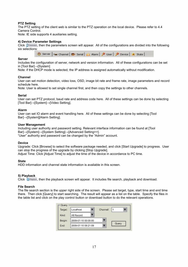
4) Device Parameter SettingsClick , then the parameters screen will appear. All of the configurations are divided into the following six selections:
ServerIncludes the configuration of server, network and version information. All of these configurations can be set in [Tool Bar]→[System]Note: if the DHCP mode is selected, the IP address is assigned automatically without modification.
ChannelUser can set motion detection, video loss, OSD, image bit rate and frame rate, image parameters and recordschedule here.Note: User is allowed to set single channel first, and then copy the settings to other channels.
SerialUser can set PTZ protocol, baud rate and address code here. All of these settings can be done by selecting [Tool Bar]→[System]→[Video Setting].
AlarmUser can set IO alarm and event handling here. All of these settings can be done by selecting [Tool Bar]→[System][Alarm Setting].
User ManagementIncluding user authority and password setting. Relevant interface information can be found at [Tool Bar]→[System]→[System Setting]→[Advanced Setting>>].“User” authority and password can be changed by the “Admin” account.
DeviceUpgrade: Click [Browse] to select the software package needed, and click [Start Upgrade] to progress. User can stop the progress of the upgrade by clicking [Stop Upgrade].Adjust Time: Click [Adjust Time] to adjust the time of the device in accordance to PC time.
StateHDD information and channel state information is available in this screen.
5) PlaybackClick , then the playback screen will appear. It includes file search, playback and download.
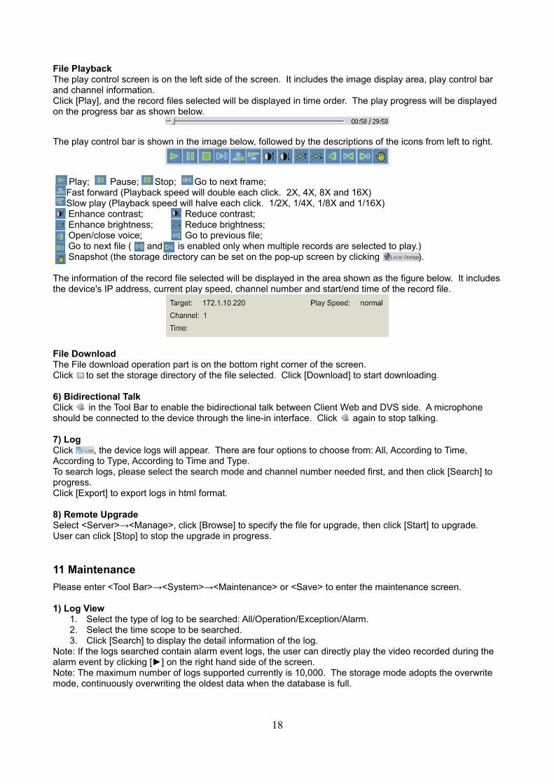
File SearchThe file search section is the upper right side of the screen. Please set target, type, start time and end time there. Then click [Query] to start searching. The result will appear as a list on the table. Specify the files in the table list and click on the play control button or download button to do the relevant operations.
17
File PlaybackThe play control screen is on the left side of the screen. It includes the image display area, play control bar and channel information.Click [Play], and the record files selected will be displayed in time order. The play progress will be displayed on the progress bar as shown below.
The play control bar is shown in the image below, followed by the descriptions of the icons from left to right.
Play; Pause; Stop; Go to next frame;Fast forward (Playback speed will double each click. 2X, 4X, 8X and 16X)Slow play (Playback speed will halve each click. 1/2X, 1/4X, 1/8X and 1/16X)
Enhance contrast; Reduce contrast; Enhance brightness; Reduce brightness; Open/close voice; Go to previous file; Go to next file ( and is enabled only when multiple records are selected to play.) Snapshot (the storage directory can be set on the pop-up screen by clicking ).
The information of the record file selected will be displayed in the area shown as the figure below. It includesthe device's IP address, current play speed, channel number and start/end time of the record file.
File DownloadThe File download operation part is on the bottom right corner of the screen.Click to set the storage directory of the file selected. Click [Download] to start downloading.
6) Bidirectional TalkClick in the Tool Bar to enable the bidirectional talk between Client Web and DVS side. A microphone should be connected to the device through the line-in interface. Click again to stop talking.
7) LogClick , the device logs will appear. There are four options to choose from: All, According to Time, According to Type, According to Time and Type.To search logs, please select the search mode and channel number needed first, and then click [Search] to progress.Click [Export] to export logs in html format.
8) Remote UpgradeSelect <Server>→<Manage>, click [Browse] to specify the file for upgrade, then click [Start] to upgrade. User can click [Stop] to stop the upgrade in progress.
11 Maintenance
Please enter <Tool Bar>→<System>→<Maintenance> or <Save> to enter the maintenance screen.
1) Log View1. Select the type of log to be searched: All/Operation/Exception/Alarm.2. Select the time scope to be searched.3. Click [Search] to display the detail information of the log.
Note: If the logs searched contain alarm event logs, the user can directly play the video recorded during the alarm event by clicking [►] on the right hand side of the screen.Note: The maximum number of logs supported currently is 10,000. The storage mode adopts the overwrite mode, continuously overwriting the oldest data when the database is full.
18

2) UpgradeThe upgrade modes supported now are USB/IE/Remote Software:
• USB: Please make sure the USB device is connected correctly and the upgrade applications have already been copied onto the USB root directory. Please follow the prompts to complete.After accomplishing the upgrade, the restart prompt will appear. Please restart the device, and the latest software will be automatically installed.
• IE: Please refer to 5.2.2 Device Parameter Settings for details.• Remote Software: Please follow the user's manual of the remote software to operate.
3) Device InformationHDD Size: Displays the current total capacity of the HDD, with the remaining capacity.Hardware Version: Displays the version of the hardware.Software Version: Displays the version of the software.Release Date: Displays the release date for the current software.
4) Format HDDPlease make sure that all of the important record files have already been saved before formatting the HDD. Please stop all recordings before beginning to format, and follow the prompts to operate.
5) Lock OutPlease enter <Tool Bar>→<System>→<Save Setting>→<Log Out>, then the preview screen will appear together with the log-in box. Please type in the password for further operations.
6) Restore to Factory DefaultsPlease enter <Tool Bar>→<System>→<Save Settings>→<Restore Defaults> where the system will ask for confirmation. Click [Confirm] to proceed with the restoring process.Note: Please refer to Appendix VI for default values.Note: The system language, time, camera P/N system and network settings (IP address, subnet mask, gateway, HTTP port) will not be recovered by restoring to factory defaults.
7) Input/output parametersPlease enter <Tool Bar>→<System>→<Maintenance> when the USB is connected, then the device setting parameters can be exported to the USB device. Parameters can then be reimported to the device from USB, then reboot the device and the parameters will take effect.Note: When importing parameters from a USB device, only import parameters from a DVR with the same SKU or model number. Importing incompatible parameters may permanently damage the device.
8) Auto-maintenancePlease enter <Tool Bar>→<System>→<Maintenance>. Maintenance will not reboot automatically if auto-maintenance is off. There are three types of maintenance: per day, per week and per time.
19

12 Advanced Settings
Note: Operations in this chapter require permission referring to the current user's authority. Please use the admin account to log in.
1) System SettingsPlease enter <Tool Bar>→<Settings>→<System>→[Advanced Settings>>]
• Select <PREVIEW CRUISE>→[>>] to enter the setting screen. Set the preview cruise interval, 1/4/9cruise. It will take effect after saving the settings, where the screen will cruise in accordance to the setting intervals over the segmentation preview.
• Select <DVR IDNUMBER> and the number entered can be between 1 ~ 99. The remote controller and 485 keyboard can control the device one on one when setting the same number.
• Select <SPOT SETTING>→[>>] to enter the setting screen. Set SPOT channel and time, the DWELL time sets the period for which a channel can be selected.
• Click [Add] to add the channel to the Matrix output. After being saved, the video output will take effect. All video channels connected with video inputs to the DVR can be sequentially switched for SPOT monitoring output.
• Select <DST>→[>>] to enter DST (Daylight Savings Time) settings. Users can set beginning and ending dates and times of DST. Device will automatically adjust the time after being saved.
• After starting <menu timeout>, when there is no mouse motions on the menu, preview screen or search screen for a certain time, the control device will automatically lock the screen. User needs tore-login to unlock the screen. (PTZ, video playback and back-up screens will never lock).
• Select <Channel Lock>→[>>] to enter the channel lock setting screen. Click the channel as desired,then select [OK]. The user cannot see the locked channel after they log out. Only the admin account can set and unlock channel lock settings.
Note: <System setup>→<Advanced Settings>, user can set recourse distribution mode, code mode and playback mode.
2) User ManagementPlease enter <Tool Bar>→<Setting>→<System Setup>→<Advanced Setting>. Select <ADD USER>→[>>] to enter the settings screen. The password for the new user is 111111, then the user can enter <Tool Bar>→<Setting>→<System>→<Password Settings> to modify the password. Select <DEL USER>→[>>] to enter the setting screen, then the Admin can delete the specified user.Select <AUTHORITY MANAGE>→[>>] to enter the settings screen. Authority settings contain the authority options for local and remote settings.
Fig IV 3 Authority Settings
Move the highlight around the options using the [Direction] buttons. Press [OK] button or click the mouse to select the option.
3) Advanced Setting of RecordPlease enter <Tool Bar>→<Setting>→<Record>→[Advanced Setting>>]→<SUB STREAM>, select Enable, press [>>] to enter the setting screen. The user can then customize the sub-stream frame rate and bit rate. Sub-stream supports 1-15 frame rates, and 32K-512K bit rates.
20

4) Advanced Setting of VideoPlease enter <Tool Bar>→<Video>→[Advanced Setting>>]
• Motion HandlingAfter setting the area for motion detection, the events can be linked to those handling “Record”, “Alarm Out”, “Buzzer” or “Upload”.Note: Please refer to 4.2.2 Motion Detection Settings for instructions on setting detection areas and sensitivity.
• Video Lost HandlingAfter the selected video channel has been lost, the incident can be handled by “Alarm Out”, “Buzzer”or “Upload”.
• Channel Name SettingAfter the selected video channel has been lost, the incident can be handled by “Alarm Out”, “Buzzer”or “Upload”. User can input the channel name through the keyboard, only accepting letters. Then select [OK] to confirm the settings.
21

Chapter Five: Appendix
1 Specifications
Table VI 1 Specifications
DVR Type 4 Channel DVR 8 Channel DVR
SystemLinus 2.6 O/SPentaplex Operation: record, playback, preview and network browse, backup supported.
I/O Interface
Video Input
4 channel, BNC, 1Vp-p, 75Ω PAL (625 line, 50 f/s)NTSC (525 line, 60 f/s)SECAM (625, 50 f/s)
8 channel, BNC, 1Vp-p, 75Ω PAL (625 line, 50 f/s)NTSC (525 line, 60 f/s)SECAM (625, 50 f/s)
Audio Input 4 channel, RCA, 2Vp-p, 600Ω
VGA Output 1 channel, DIN-15(optional); 800x600@60hz, 1024x768@60Hz, 1280x1024@60Hz, 1440x900@60Hz
CVBS Output 1 channel, BNC, 1Vp-p, 75Ω
Audio Output 1 channel, BNC, 2Vp-p, 600Ω
USB Interface Support USB storage device, USB mouse, USB burner
RS422 1 port, receiving and transmitting duplex supported
Network Interface RJ45 – 10/100M self-adaptive
Alarm Input 4 channel NO/NC
Alarm Output 1 channel NO/NC, relay: 30VDC 1A, 125VAC 1A
SATA Interface 1 SATA port, 1 SATA HDD up to 1TB supported.
Video & Audio
Video Video Compression H.264 Baseline
Video Standards PAL/NTSC/SECAM
Video Compression Resolution
PAL: 352x288(CIF), NTSC: 352x240(CIF)PAL: 704x288(Half D1/2CIF), NTSC 704x240(Half D1/2CIF)PAL: 704x576(D1/4CIF), NTSC 704x480(D1/4CIF)
Frame Rate PAL: 25F/S/CH 1,3,5,12,25 and user-defined optional;NTSC: 30F/S/CH 1,3,7,15,30 and user-defined optional.
Video Output Bit Rate 32kbps-2048kbps (14Mbyte/hour – 922Mbyte/hour)
Preview Resolution PAL: 720x576(D1), horizontal line 550, vertical line 450NTSC: 720x480(D1), horizontal line 550, vertical line 400
Playback Resolution PAL: 352x288(CIF), horizontal line 300, vertical line 250NTSC: 352x240(CIF), horizontal line 300, vertical line 220
Audio Audio Compression G.726 ADPCM
Input/Output Sampling Rate
8KHz
Audio Channel Type Mono
Sampling Bit 16bit
22
Environmental Power Supply DC 12V 3A, position inside, negative outside
Operating Temp. 0C ~ +50C
Operating Humidity 10% ~ 90%RH
Power Consumption <12W (without HDD)
Dimensions 340 x 260 x 50mm (W x D x H)
Table VI 2 Main Functions
Main Functions
Operating Interface Multiple control methods: mouse, IR remote controller, front panel and GUI with naviagation supported.Recording status and alarm status can be displayed directly on desktop or front panel.
Record Five recording modes: Manual, Schedule, Motion Detection, Alarm and Motion Detection & Alarm supported.Selectable Record quality: Best, High, Mid, Low and User-defined.
Playback Play progress bar supported.Multiple channel video/audio playback simultaneously.Play, pause, stop, single frame forward, fast forward and backward (up to 4/9 when playback is in 4 channels) supported.
Backup Multiple backup modes: USB disk, USB HDD, USB CD-RW and DVD-RW supported. The output format can be H.264 RAW.
Network Ipv4, PPPoE client, DHCP client and TCP/UDP protocol supported.Web client and Client Application Software are provided for remote configuration, video browse, local recording, local and remote playback and remote PTZ control.Network transmitting supports independent coding.The time delay of LAN is less than 300ms.
Log Operation The log of operations are alarms will be saved automatically. User can directly play the record files that have been recorded when the alarm events occur.
PTZ Control Multiple protocols: Pelco-P, Pelco-D, and Samsung etc.. supported.Upgrades of protocols supported.Multiple PTZ operations: Pan, Tilt, Zoom, Preset, Sequence, Track and Auxiliary Switch supported.
Alarm Management 4 channel alarm input NO/NC supported.Motion detection and alarm of video loss supported.Trigger recording, linkage PTZ preset and Bee alarm supported.The alarm information can be sent to web client or client application software through the network.
Account Management
Multi-accounts supported. Users can set and recover passwords, authentication management.
Auxiliary Function Hardware watch dog supported. Device will be restarted if operations are not responded to for 30 seconds or longer.
23

2 Methods of Calculating HDD Capacity
1) Calculate the maximum capacity of the built-in hard disk.
Timing Recording:• Step 1: Calculate the maximum capacity of the hard disk needed in selected channel per hour, which
we will classify as Si(MByte) with i representing the channel number. With the bit rate of the channelbeing classified as D (Kbit/s), the formula is as follows:Si = (Dx3600) / (8x1024) = D x 0.439453125 MB
• Step 2: Confirm the storage length time, which we will classify as T hours. The total maximum capacity of the hard disk needed in the selected channel for T hours is:St = T x S1
• Step 3: Confirm the total numbers of the channels, set here as n. The total maxmimum capacity of the hard disk needed, represented as Sc below is:Sc = S1 + S2 + … + Sn
Alarm Recording:• Suppose the rate of alarm is a%. The capacity of the hard disk needed in alarm recording (classified
here as Sa) is:Sa = Sc x a%
2) Calculate the compression bit rate for recording T hours.
*Timing Recording• Step 1: Support the capacity of the hard disk is S and the total numbers of channels is n. The
capacity of the hard disk needed per channel (known as Di) is:Di = S / n
• Step 2: Support the total recording time is T. The capacity of the hard disk needed per hour per channel (known as Dt) is:Dt = Di / T
• Step 3: The bit rate of all the channels (known as Dc) is:Dc = Dt x (8 x 1024) / 3600 = Dt x 2.2756 (Kbit/s)
*Alarm RecordingStep 1: The rate of alarm (known as a%), the capacity of the hard disk as S and the total numbers of the channel as n. The capacity of the hard disk needed per channel is Di:Di = (S/n) x a%Step 2: With the time length of the recording (known as T (hours)), the capacity of the hard disk needed per hour per channel (known as Dt) is:Dt = Di / TStep 3: The bit rate of all channels (known as Dc) is:Dc = Dt x (8x1024) / 3600 = Dt x 2.2756 (Kbit/s)
24

3 Default Values
Table VI 4 Default Values
Menu Options in menu Default
System Settings
LANGUAGE Multi-language Chinese
Video Standard PAL, NTSC, SECAM Auto Adjust
VGA Setting 800x600@60hz, 1024x768@60Hz, 1280x1024@60Hz, 1440x900@60Hz
800x600@60Hz
Time Format 12 Hours, 24 Hours Time Format
Time Setting Click into submenu screen Year-Month-Day-Hour:Minute-PM
DST Off, on, click into submenu screen Off
Password Setting Click into submenu screen Admin: 111111 User: 111111
HDD Overwrite On, off Reach the maximum number of users
Add User Click into submenu screen Click into submenu screen
Delete User Click into submenu screen
Authority Change Click into submenu screen Admin
Preview Cruise Off, on Cruise time: 2,5,10,15,20 secs;Cruise mode: 1,3,9
Device ID number 1 ~ 99 1
Menu time-out setting
Off, 30 secs, 1 min, 5 min Off
Channel lock setting
Click into submenu screen
Recourse Distribution Mode
Click into submenu screen
Video Settings
Record Schedule Click into submenu screen 24 Hours
Video Quality Best, High, Mid, Low Best
Record Frame Rate
PAL: Full, 12, 6, 3, 1, User-DefinedNTSC: Full, 15, 7, 3, 1, User-DefinedSECAM: Full, 12, 6, 3, 1, User-Defined
Full
Record Source Video, Video & Audio Video & Audio
OSD Setting Channel name, Channel name and timestamp, timestamp, none
Channel name and timestamp
Record Resolution
CIF, Half D1, D1 CIF
Sub-code Frame rate and data bit user-defined:Frame rate: 1~15fpsDate bit: 32~512kbps
On;Frame rate: 5fpsData bit: 96kbps
PTZ protocol Pelco-P, Pelco-D, Samsung, Panasonic, Yaan, Yiboer, Pelco-p_call98, vts, pelco-d_cg, pelco-d_lx, pelco-d_cf, pelco-d_mj, pelco-p_mj, pelco-d_hd, pelco-d_dt, pelco-d_jg, jy2000, pelco-d_dsx, delco-d_qg, pelco-d_fh, pelco-d_htz, pelco-d_xz, pelco-d_pts, td500, clt-618, philips, pelco-d_jg
Pelco-P
PTZ Baud rate 1200, 2400, 4800, 9600 2400
25
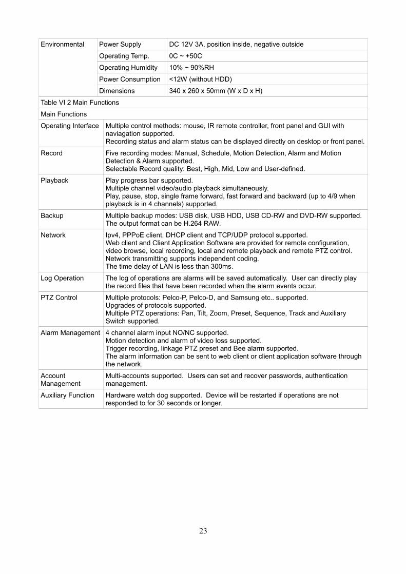
Video Settings (Cont...)
PTZ address Click into submenu Channel 1
Colour Settings Brightness, contrast, hue, saturation 6/6/8/8
Motion Detection Highest sensitivity, Normal sensitivity, Low sensitivity
Normal sensitivity
Mosaic On, off, click into sub menu screen Off
Motion Detection Event Handling
Record, zoom out, alarm out, buzzer, upload, email
Record
Video Loss Handling
Alarm out, sound, report to center, email
Off
Channel Name Settings
Click into the settings CH1/2/3/4/5/6/7/8
Network Settings
Network Static IP, Dynamic Address of IP, PPPoE
Static IP
IP Address Click into submenu screen 192.168.0.10
Subnet Mask Click into submenu screen 255.255.255.0
Gateway Click into submenu screen 192.168.0.1
HTTP Port Click into submenu screen 80
Command Port Click into submenu screen 5050
Media Port Click into submenu screen 6050
PPPoE Setting ON, OFF, Click into submenu screen Off
PPPoE Address Click into submenu screen 0.0.0.0
DNS Address Click into submenu screen 0.0.0.0
Dynamic Domain Name
ON, OFF Off
Auto Register ON, OFF Off
File Sharing Click to select or deselect Off
Email Setting Click into submenu screen
Mobile Port Click into submenu screen 7050
UpnP Setting Off, on, Click into submenu screen Off
Dedicated Server Off, on, Click into submenu screen Off
FTP Setting Off, on, Click into submenu screen Off
IP white/black list Off, white list, black list, Click into submenu screen
Off
Time Synchronized
Off, on, Click into submenu screen Off
Alarm Settings
Alarm Input Type N/O, N/C N/O
Event Handling Record, PTZ preset, zoom out, alarm out, buzzer, upload, email
Trigger alarm output, buzzer and email.
Alarm Setting Off, 1~10 ON
Alarm Zoom Out 1~10 seconds, OFF OFF
Abnormal Device Click into sub menu screen, alarm out, buzzer, upload, email, FTP file upload
All
26
4 Introduction of Mobile Phone Monitoring
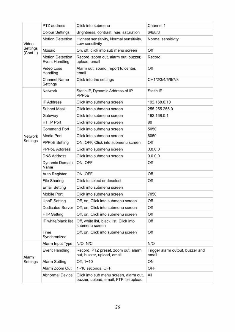
1) Configuration of server (DVR)Setup device, type in user name and password to log in.Shown as figure V1-3 below, click [Net] and then click [Next Page] to enter into the [Mobile Port] screen.
Fig VI-5 DVR sub-stream configuration Fig VI-6 DVR sub-stream settings
Shown as the figure V1-6 above to set [FPS] and [Bitrate], the frequently-used frame rate is 3fps, and data bit is 128kbps.
Installation and running of client (mobile phone) procedures.Versions supported client side are as follows:English/Simplified Chinese/Traditional Chinese Client side of Symbian60 3rd Operation System;English/Traditional Chinese client side of WinMobile5.0/6.0/6.1 Operation System;iPhone mobile is supportedNote: We will use WinMobile6.0 as the example to show how to install and run the procedure.
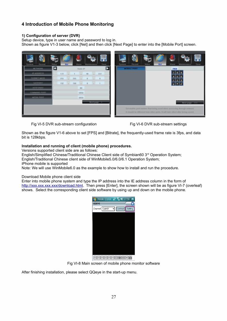
Download Mobile phone client sideEnter into mobile phone system and type the IP address into the IE address column in the form of http://xxx.xxx.xxx.xxx/download.html. Then press [Enter], the screen shown will be as figure VI-7 (overleaf) shows. Select the corresponding client side software by using up and down on the mobile phone.
Fig VI-8 Main screen of mobile phone monitor software
After finishing installation, please select QQeye in the start-up menu.
27
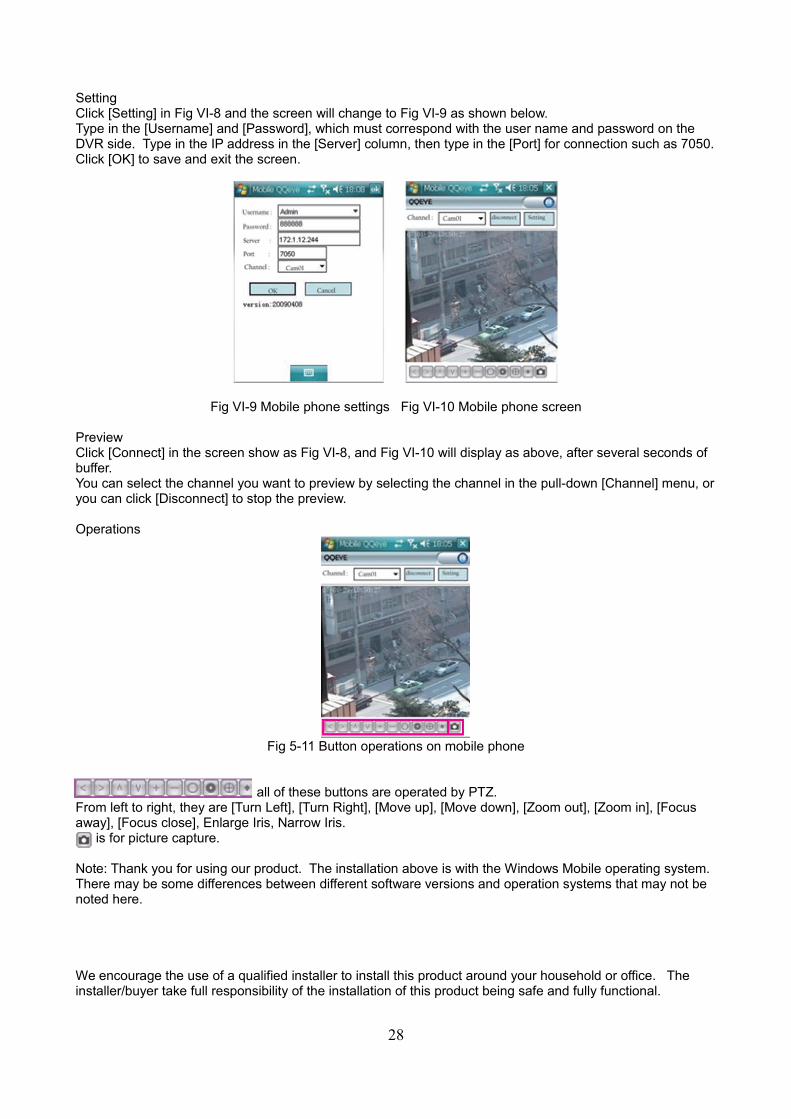
SettingClick [Setting] in Fig VI-8 and the screen will change to Fig VI-9 as shown below.Type in the [Username] and [Password], which must correspond with the user name and password on the DVR side. Type in the IP address in the [Server] column, then type in the [Port] for connection such as 7050.Click [OK] to save and exit the screen.
Fig VI-9 Mobile phone settings Fig VI-10 Mobile phone screen
PreviewClick [Connect] in the screen show as Fig VI-8, and Fig VI-10 will display as above, after several seconds of buffer.You can select the channel you want to preview by selecting the channel in the pull-down [Channel] menu, oryou can click [Disconnect] to stop the preview.
Operations
Fig 5-11 Button operations on mobile phone
all of these buttons are operated by PTZ.From left to right, they are [Turn Left], [Turn Right], [Move up], [Move down], [Zoom out], [Zoom in], [Focus away], [Focus close], Enlarge Iris, Narrow Iris.
is for picture capture.
Note: Thank you for using our product. The installation above is with the Windows Mobile operating system. There may be some differences between different software versions and operation systems that may not be noted here.
We encourage the use of a qualified installer to install this product around your household or office. The installer/buyer take full responsibility of the installation of this product being safe and fully functional.
28