table of contents page - minnesota department of ... · table of contents page ... 7-3.00 legality...
TRANSCRIPT

August 15, 2008 TRAFFIC ENGINEERING MANUAL
7-1
Chapter 7PAVEMENT MARKING
TABLE OF CONTENTS Page
7-1.00 INTRODUCTION . . . . . . . . . . . . . . . . . . . . . . . . . . . . . . . . . . . . . . . . . . . . . . . . . . . . . . . . . .7-31.01 Purpose1.02 Scope1.03 Chapter Organization
7-2.00 GLOSSARY . . . . . . . . . . . . . . . . . . . . . . . . . . . . . . . . . . . . . . . . . . . . . . . . . . . . . . . . . . . . . .7-3
7-3.00 LEGALITY . . . . . . . . . . . . . . . . . . . . . . . . . . . . . . . . . . . . . . . . . . . . . . . . . . . . . . . . . . . . . . .7-43.01 Legal Authority3.02 Responsibility for Placement and Removal3.03 Legal Effect
7-4.00 PAVEMENT MARKINGS . . . . . . . . . . . . . . . . . . . . . . . . . . . . . . . . . . . . . . . . . . . . . . . . . . . .7-54.01 Materials4.02 Standards and Specifications4.03 Application Guidelines4.04 No-Passing Zone Surveys4.05 Standard Spotting Procedure4.06 Special Markings
7-5.00 OBJECT MARKINGS . . . . . . . . . . . . . . . . . . . . . . . . . . . . . . . . . . . . . . . . . . . . . . . . . . . . . .7-185.01 Purpose5.02 Types of Object Markers5.03 Applications and Guidelines
7-6.00 DELINEATION . . . . . . . . . . . . . . . . . . . . . . . . . . . . . . . . . . . . . . . . . . . . . . . . . . . . . . . . . . . .7-216.01 Types and Materials6.02 Delineator Location6.03 Deer Reflectors
7-7.00 REFERENCES . . . . . . . . . . . . . . . . . . . . . . . . . . . . . . . . . . . . . . . . . . . . . . . . . . . . . . . . . . .7-22

October 31, 2009 TRAFFIC ENGINEERING MANUAL
7-2
List of FiguresFigure Description Page7.1 Two-Lane, Two-Way Roadway Pavement Marking Details . . . . . . . . . . . . . . . . . . . . . . . . . .7-237.2 Multi-lane Undivided Roadway Pavement Marking Details . . . . . . . . . . . . . . . . . . . . . . . . . .7-247.3 Two-Way Left Turn Lane Pavement Marking Details . . . . . . . . . . . . . . . . . . . . . . . . . . . . . . .7-257.4 Passing Lane Section Pavement Markings . . . . . . . . . . . . . . . . . . . . . . . . . . . . . . . . . . . . . .7-267.5A Major Intersection Pavement Markings . . . . . . . . . . . . . . . . . . . . . . . . . . . . . . . . . . . . . . . . .7-277.5B Major Intersection Pavement Markings . . . . . . . . . . . . . . . . . . . . . . . . . . . . . . . . . . . . . . . . .7-287.6 Ramp and Through Lane Pavement Markings . . . . . . . . . . . . . . . . . . . . . . . . . . . . . . . . . . .7-297.7 Exit Ramp on Curved Roadway Pavement Markings . . . . . . . . . . . . . . . . . . . . . . . . . . . . . .7-307.8 Removed7.8A Auxiliary Lane Pavement Markings . . . . . . . . . . . . . . . . . . . . . . . . . . . . . . . . . . . . . . . . . . .7-317.8B Auxiliary Lane Pavement Markings . . . . . . . . . . . . . . . . . . . . . . . . . . . . . . . . . . . . . . . . . . . .7-327.9 Turn Lane & Left Turn Island Pavement Markings . . . . . . . . . . . . . . . . . . . . . . . . . . . . . . . .7-337.10 Bypass Lane Pavement Markings . . . . . . . . . . . . . . . . . . . . . . . . . . . . . . . . . . . . . . . . . . . . .7-347.11 Divided Roadway Transition Pavement Markings . . . . . . . . . . . . . . . . . . . . . . . . . . . . . . . . .7-357.12 Undivided Roadway Transition Pavement Markings . . . . . . . . . . . . . . . . . . . . . . . . . . . . . . .7-367.13 Truck Climbing Lane Pavement Markings . . . . . . . . . . . . . . . . . . . . . . . . . . . . . . . . . . . . . . .7-377.14 Railroad Crossing with Truck Stopping Lane Pavement Markings . . . . . . . . . . . . . . . . . . . .7-387.15 Free Right Turn Lane Pavement Markings . . . . . . . . . . . . . . . . . . . . . . . . . . . . . . . . . . . . . .7-497.16 No Passing Zone - Survey Procedure for a Vertical Curve . . . . . . . . . . . . . . . . . . . . . . . . . .7-407.17 Removed7.18 Spotting Symbols for Pavement Striping . . . . . . . . . . . . . . . . . . . . . . . . . . . . . . . . . . . . . . . .7-417.19 Pedestrian Crosswalk Markings . . . . . . . . . . . . . . . . . . . . . . . . . . . . . . . . . . . . . . . . . . . . . . .7-427.20 Pedestrian Crosswalk Markings - Zebra Design . . . . . . . . . . . . . . . . . . . . . . . . . . . . . . . . . .7-437.21 School Zone Markings - Unsignalized Intersection . . . . . . . . . . . . . . . . . . . . . . . . . . . . . . . .7-447.22 Stop Ahead & Stop Line Pavement Markings . . . . . . . . . . . . . . . . . . . . . . . . . . . . . . . . . . . .7-457.23A Parking Area Pavement Markings - Disabled Parking Details . . . . . . . . . . . . . . . . . . . . . . . .7-467.23B Parking Area Pavement Markings - Disabled Parking Details . . . . . . . . . . . . . . . . . . . . . . . .7-477.23C Parking Area Pavement Markings - Parking Stall Details . . . . . . . . . . . . . . . . . . . . . . . . . . .7-487.23D Parking Area Pavement Markings - Truck Parking Stall Details . . . . . . . . . . . . . . . . . . . . . .7-497.24 Airplane Pavement Markings . . . . . . . . . . . . . . . . . . . . . . . . . . . . . . . . . . . . . . . . . . . . . . . . .7-507.25 High Occupancy Vehicle (HOV) Pavement Markings . . . . . . . . . . . . . . . . . . . . . . . . . . . . . .7-517.26 Commonly Used Object Markers . . . . . . . . . . . . . . . . . . . . . . . . . . . . . . . . . . . . . . . . . . . . . .7-527.27 Narrow Bridge Signing & Delineation . . . . . . . . . . . . . . . . . . . . . . . . . . . . . . . . . . . . . . . . . .7-537.28 One-Lane Bridge Signing & Delineation . . . . . . . . . . . . . . . . . . . . . . . . . . . . . . . . . . . . . . . .7-547.29 Unprotected Large Culvert & Cattle Pass Delineation . . . . . . . . . . . . . . . . . . . . . . . . . . . . . .7-557.30 Delineator Types & Installation . . . . . . . . . . . . . . . . . . . . . . . . . . . . . . . . . . . . . . . . . . . . . . .7-567.31 Delineator Types & Installation . . . . . . . . . . . . . . . . . . . . . . . . . . . . . . . . . . . . . . . . . . . . . . .7-577.32 Divided-Highway Intersection Delineation . . . . . . . . . . . . . . . . . . . . . . . . . . . . . . . . . . . . . . .7-587.33 Diamond Interchange Delineation - Partial and Full Lighting . . . . . . . . . . . . . . . . . . . . . . . .7-597.34 Diamond Interchange Delineation - Unlit . . . . . . . . . . . . . . . . . . . . . . . . . . . . . . . . . . . . . . . .7-607.35 Cloverleaf Interchange Delineation - Full Lighting . . . . . . . . . . . . . . . . . . . . . . . . . . . . . . . . .7-617.36 Roundabout Intersection Pavement Markings . . . . . . . . . . . . . . . . . . . . . . . . . . . . . . . . . . . .7-62
List of ChartsChart Description Page7-1 Removed7-2 Minimum Length of a No Passing Zone in Advance of a Stop Condition . . . . . . . . . . . . . . .7-637-3 Minimum Passing Sight Distance . . . . . . . . . . . . . . . . . . . . . . . . . . . . . . . . . . . . . . . . . . . . .7-637-4 Minimum Distance or Gap Between No-Passing Zones . . . . . . . . . . . . . . . . . . . . . . . . . . . .7-637-5 Object Markers . . . . . . . . . . . . . . . . . . . . . . . . . . . . . . . . . . . . . . . . . . . . . . . . . . . . . . . . . . . .7-647-6 Delineator Fabrication Details . . . . . . . . . . . . . . . . . . . . . . . . . . . . . . . . . . . . . . . . . . . . . . . .7-657-7 Finding the Degree of Curve for a Horizontal Curve . . . . . . . . . . . . . . . . . . . . . . . . . . . . . . .7-667-8 Crosswalk Warrants . . . . . . . . . . . . . . . . . . . . . . . . . . . . . . . . . . . . . . . . . . . . . . . . . . . . . . . .7-67

October 31, 2009 TRAFFIC ENGINEERING MANUAL
7-3
7-1.00 INTRODUCTION
7-1.01 Purpose
It is MN/DOT's mission to provide appropriate pavement markings on all highways 365 days per year.
This chapter gives specific guidelines for the use of pavement markings. The Minnesota Manual on UniformTraffic Control Devices (MN MUTCD), sets forth general standards, while this manual outlines preferred practiceswithin the MN MUTCD standards.
7-1.02 Scope
Standards for the application of markings and delineation are set forth in the MN MUTCD, and those basicprinciples must be followed by the engineers, technicians, and maintenance personnel responsible for the design,selection, placement, and documentation of these devices. The Traffic Engineering Manual (TEM) does notduplicate or violate the standards established in the MN MUTCD. The TEM presents the preferred practice in theapplication of pavement markings, object markers, and delineators. Information presented in this chapter includes:(1) types and use of materials, (2) general principles to be followed, (3) design details, including standards andspecifications, and (4) the specific use of markings and delineation. Users of the TEM should be completelyfamiliar with the current MN MUTCD requirements before attempting to apply the guidelines established in thischapter.
7-1.03 Chapter Organization
Important terms used in this chapter are defined in the Glossary of the TEM. The remaining sections of the chapterdiscuss: (1) legality, (2) pavement markings, (3) special markings, (4) object markings, (5) delineation.
7-2.00 GLOSSARY
Appropriate Pavement Marking - One that meets or exceeds the standards defined in the MN MUTCD includingany minimum levels of retroreflectivity, when weather permits. During winter operations, pavement markingsshould provide presence after bare pavements are attained.
Centerline - A line indicating the division of the roadway between traffic traveling in opposite directions.
Channelizing Line - A line which directs traffic and indicates that traffic should not cross the line.
Continental Block - White longitudinal lines placed at crosswalks that are parallel to the flow of traffic.
Contrast Marking - A marking placed alongside and/or on the ends of a light colored marking and/or within thewhole groove for the light marking. Black may be used in combination with the light markings on concrete toenhance the visibility of the marking. The light marking is typically placed in the middle of the black contrastmarking.
Delineator - A light-reflecting device mounted at the side of the roadway, in a series with others, to indicate thealignment of the roadway.
Durable Markings - Marking materials designed to provide year round presence and retroreflectivity for at leasttwo years.
Edge Line - A line which indicates the edge of the roadway.
Hazardous Waste - With respect to removal of pavement markings, waste debris created may be toxic (seeToxicity in Specified Products) and/or flammable and require handling and disposal procedures prescribed bywaste management laws, rules, and regulations.
CHAPTER 7 - PAVEMENT MARKINGS

August 15, 2008 TRAFFIC ENGINEERING MANUAL
7-4
Lane Line - A line separating two lanes of traffic traveling in the same direction.
Non-Hazardous Waste - With respect to the removal of pavement markings, waste debris may be disposed ofusing less stringent criteria. This would make it acceptable at some in-state waste facilities as designated by theOffice of Environmental Services.
Object Markers - Markings intended for use on obstructions within or adjacent to the roadway.
Pavement Markings - All lines, symbols, words, colors, or other devices, except signs and power-operated trafficcontrol devices, set into the surface of, applied upon, or attached to the roadway.
Roadway - That portion of a highway used for vehicular travel, exclusive of the berm or shoulder. A dividedhighway includes two or more separate roadways.
Sharks Teeth - Triangular shaped markings placed at roundabout intersection as a yield line.
Stop Line - A line which indicates where vehicles should stop when directed to stop.
Toxics in Specified Products - Minnesota Statute 115A.9651 prohibits the use of toxic heavy metals in any ink,dye, pigment, paint, or fungicide after September 1, 1994. The prohibited toxic heavy metals are lead, cadmium,mercury, and hexavalent chromium. They may be found in older pavement markings, particularly lead andchromium in yellow markings. Consequently, non-toxic pavement markings must be specified in contracts andpurchases.
Waste Debris - With respect to pavement marking materials, white or yellow-colored paint/bituminous or concretemixtures generated by the removal of pavement markings.
7-3.0 LEGALITY
7-3.01 Legal Authority
Minnesota Statutes 169.06 (Subdivisions 1-4) and 169.07 establishes the legal authority for the Department andlocal units of government to: (1) place and maintain markings, (2) require obedience to official markings, (3)prohibit the display of unauthorized markings, and (4) prohibit interference with official markings. Markings shallbe placed only by the authority of the public body having jurisdiction over the highway, road, or street for thepurpose of regulating, warning, or guiding traffic. Pavement and curb markings, object markers, and delineatorsare all normally within highway, road, or street rights-of-way and, therefore, should never be installed except underpublic authority.
Two 1990 Session Laws, Chapters 482 and 497, modified handicapped parking requirements for the disabled.
7-3.02 Responsibility for Placement and Removal
Permanent pavement markings are the responsibility of the governing road authority. These markings may beplaced or removed by maintenance personnel or contractor
7-3.03 Legal Effect
Minnesota Statutes, Section 169.18, refers to specific distinctive pavement markings which prohibit the driverfrom making specified maneuvers or guide the driver in certain paths.
It is important that correct markings are used since markings have specific meanings defined in the law. The useof inappropriate markings and delineators could lead to legal claims of negligence.
August 15, 2008 TRAFFIC ENGINEERING MANUAL
7-5
7-4.0 PAVEMENT MARKINGS
7-4.01 Materials
The basic requirements for pavement markings are: (1) specified colors are identifiable day and night and (2)minimum visibility standards are maintained throughout the material's lifetime. Factors considered in selectingmarkings are durability, workability, drying and non-track time, accommodation of heavy traffic volumes,replacement of material, safety, and environmental concerns.
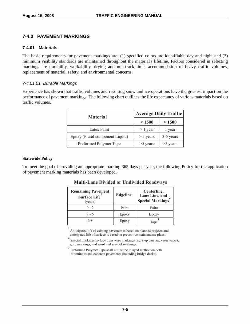
7-4.01.01 Durable Markings
Experience has shown that traffic volumes and resulting snow and ice operations have the greatest impact on theperformance of pavement markings. The following chart outlines the life expectancy of various materials based ontraffic volumes.
Statewide Policy
To meet the goal of providing an appropriate marking 365 days per year, the following Policy for the applicationof pavement marking materials has been developed.
0 - 2
2 - 6
6 +
Paint
Epoxy
Epoxy
Paint
Epoxy
Tape3
Special Markings2
Centerline,Lane Line, and
Remaining Pavement
Multi-Lane Divided or Undivided Roadways
Surface Life1 Edgeline
(years)
1
2
3
Anticipated life of existing pavement is based on planned projects andanticipated life of surface is based on preventive maintenance plans.
Special markings include transverse markings (i.e. stop bars and crosswalks),gore markings, and word and symbol markings.
Preformed Polymer Tape shall utilize the inlayed method on bothbituminous and concrete pavements (including bridge decks).
Latex Paint
Epoxy (Plural component Liquid)
Preformed Polymer Tape
> 1 year
> 5 years
>5 years
< 1500
1 year
3-5 years
>5 years
> 1500Material
Average Daily Traffic

August 15, 2008 TRAFFIC ENGINEERING MANUAL
7-6
All marking materials shall be on Mn/DOT's Qualified Products List and shall be installed according to themanufacturer's specifications. This may include removal of existing pavement markings and other surfacetreatments as recommended by the manufacturer.
Part VI of the MN MUTCD should be consulted for interim pavement marking requirements
7-4.01.02 Temporary Markings
Temporary markings are used in construction areas and at locations where a temporary hazard must be properlymarked until the necessary repairs or improvements can be made.
The types of temporary pavement markings which are used in Minnesota and their respective characteristics aredescribed in Chapter 8 of this Manual.
7-4.01.03 Retroreflectivity
Pavement markings which must be visible at night shall be reflectorized unless ambient illumination assuresadequate visibility. Most pavement markings are reflectorized with the exceptions of curb and parking lines.
Retroreflectorization, defined as the return of light from a vehicle head lamp to the driver's eye, is accomplishedby retroreflective elements (glass, ceramic, etc) imbedded into the marking material. Road grime, salt, dirt, dampor wet conditions, and snow plow damage reduce the retroreflectivity of a marking. Snow plowing, particularly bythe under-body plow blade type, can destroy retroreflectivity by shaving or removing the glass beads.Retroreflectivity of in place pavement markings by handheld or mobile retroreflectometers. The handheld is moreaccurate while the mobile can collect large quantities of data at highway speeds.
A mobile retroreflectometer has three major components:
1. laser and feedback sensor,
2. distance measuring device, and
3. data acquisition computer.
The data collected from retroreflectometers will be used in the development of a pavement marking managementsystem.
0 - 2
2 +
Paint
Paint
Paint
Paint
Paint
Epoxy
Paint
Epoxy
Centerline CenterlineRemaining Pavement
Two-Lane, Two-Way Roadways
Surface Life1 Edgeline Edgeline
(years)
1Anticipated life of existing pavement is based on planned projects and anticipated life ofsurface is based on preventive maintenance plans.

August 15, 2008 TRAFFIC ENGINEERING MANUAL
7-7
7-4.01.04 Removal of Markings
Markings that are no longer applicable for roadway conditions or restrictions and that might cause confusion forthe road user shall be removed or obliterated to be unidentifiable as a marking as soon as practical.
Overly aggressive removal techniques leave scars that can confuse drivers during night and wet conditions.
Do not allow excessive scarring. Any excessive scarring should be repaired to avoid wet weather confusion.
Typically, sandblasting, grinding, and high pressure water jet have been used to remove markings, but the resultsat times have been less than desirable. For larger projects, truck-mounted, hydraulically controlled, dual scarifyingdrums with a built-in vacuum system could be considered. A trailing sweeper/vacuum unit recovers the coarserpaint/surface waste mixture.
Markings may be temporarily masked with tape (not paint) until they can be removed or obliterated.
Lines and scars from line removal may look different at night. Nighttime inspections are desirable to determinethat the pavement markings are visible and understandable under day and night conditions.
7-4.02 Standards and Specifications
The Minnesota cycle length for pavement marking is 50 feet. The cycle consists of a 10 foot stripe and a 40 foot gap.
Implementation
These guidelines shall be followed on all MN/DOT striping operations:
1. All new surfaces/overlays shall be striped with the 50 foot cycle.
2. All striping done on existing surfaces shall match the cycle currently in place. If the cycle is to be changedfrom a 40 foot to a 50 foot cycle, the existing pavement markings shall be removed.
7-4.03 Application Guidelines
Where used, pavement striping shall conform to the Highway Striping Plan, Standard Plan Nos. 5-297.341,5-297.342 and Figure 7.1 as follows:
7-4.03.01 Two-Lane, Two-Way Roadways and Passing Lane Sections
1. Two-lane, Two-way roadways (see Figure 7.1) shall have:
Broken yellow centerlines
Pavement edge lines wherever there is poor color contrast between pavement and shoulders (especially atnight), where fog conditions or the unusual hazards may exist, or on approaches to piers, abutments, andretaining walls. Edge lines are used extensively by MN/DOT.
Solid yellow lines to restrict passing where required, in accordance with the warrants and criteria for suchmarkings. (See Section 7-4.04 of this chapter).
2. Passing Lane Sections
Pavement markings are needed as follows:
a. Lane Addition (see Figure 7.4)
Both the pavement edge marking and the diagonal gore marking should be installed immediately prior tothe beginning of the left lane line.

August 15, 2008 TRAFFIC ENGINEERING MANUAL
7-8
b. Passing Lane
A solid double yellow centerline pavement marking should be used to separate the lanes that carry opposingtraffic. A broken white skip pavement marking is used to separate traffic moving in the same direction.Pavement edge markings are recommended for both directions of opposing traffic in the passing lanesections.
c. At the Lane Drop
Pavement markings in the lane drop transition area should be provided in accordance with the MNMUTCD, Section 3B-9 and Figure 3B-12. Pavement edge markings are important in the lane droptransition area.
7-4.03.02 Undivided Multi-lane Roadways
Pavement Markings shall conform to Figure 7.2.
Use the following for all Multi-lane, two-way roadways (four or more lanes):
Double yellow solid line as centerline markings
Lane lines
Pavement edge lines. They are not required in urban areas with curbs.
7-4.03.03 Roadways with Two-Way Left Turn Lanes
Pavement markings shall conform to Figure 7.3.
7-4.03.04 One-Way Roadways
One-way roadways shall have the following:
Lane lines to provide for better use of each lane
Pavement edge lines on right side or both sides where needed for night visibility or where fog conditionsor other unusual hazards may be encountered.
7-4.03.05 Narrow Bridges
Bridge decks on two-lane, two-way bridges may have double yellow barrier lines depending on bridge widthand length. No-passing zones shall begin 1000 feet in advance of a narrow bridge. (see Figure 7.27)
7-4.03.06 Intersections
Supplementary pavement markings at intersections, where used, shall conform to the standards shown inFigures 7.5a and 7.5b, and.Figure 7.22.
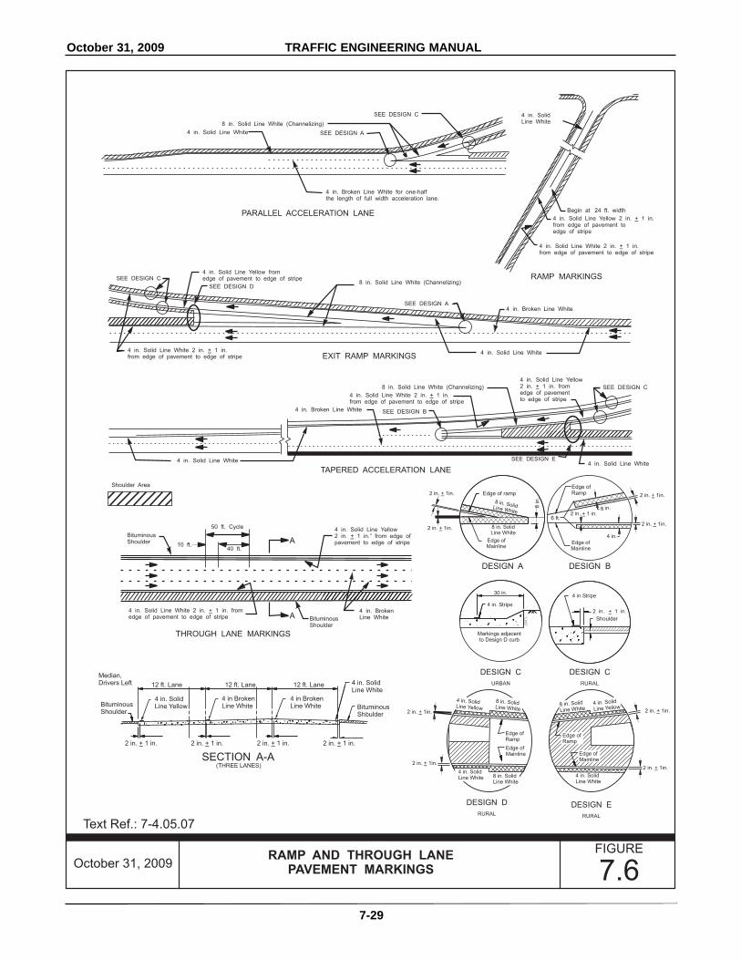
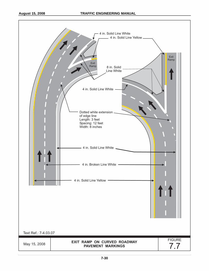
7-4.03.07 Interchange Exit and Entrance Ramps
Pavement markings for interchange ramps, where applied, shall conform to the standards shown in theHighway Striping Plan (see Figure 7.7 and Mn/DOT Standard Plan Sheet 5-297.341).
7-4.03.08 Auxiliary Lanes and Lane Drops
The purpose of this section is to clarify the use of these markings. Mn/DOT Standard Plan Sheet 5-297.342displays the size, spacing of these markings and typical applications for lane drops and auxiliary lanes.
7-4.03.09 Turn Lanes
Use of a turn lane message is not required. If the district traffic engineer determines a need, use Figure 7.9 forplacement guidance. Messages are required to supplement appropriate signing where a normal through laneis designated for turn option--through and/or turn only operation.
7-4.03.10 Bypass Lanes at Intersections
Bypass lanes at intersections should be marked as illustrated in Figure 7.10.
7-4.03.11 Obstructions in Traveled Way
See the MN MUTCD, Section 3B-10 and Figure 3B.13.
7-4.03.12 Transitions
Approaches to median islands in roadways shall be marked as illustrated in Figure 7.11. Markings for two-lane to four-lane undivided pavements shall be as shown in Figure 7.12.
7-4.03.13 Special Climbing Lanes
Pavement markings for special climbing lanes shall conform to the standards shown in Figure 7.13.
7-4.03.14 Truck Stopping Lane
Pavement markings for truck stopping lanes at railroad crossings shall be as shown in Figure 7.14.
7-4.03.15 Free Right Conditions
Pavement Markings for free right conditions shall conform to the standards shown in Figure 7.15.
7-4.03.16 Bicycle Lanes
See the MN MUTCD, Chapter 9 - Traffic Control for Bicycle Facilities.
7-4.04 No-Passing Zone Surveys
7-4.04.01 Warrants
A no-passing zone is warranted when the minimum sight distance is less than the distances shown in Chart 7-3.No-passing zone surveys shall be run at an eye height of 3.5 feet to an object height of 3.5 feet at the sight distancerequired in Chart 7-3 based upon the 85th percentile speed. The beginning of a no-passing zone shall be the pointat which the sight distance first becomes less than that specified in Chart 7-3. The end of the marking shall be thatpoint at which the sight distance becomes greater than the minimum specified in Chart 7-3. A no-passing lineshould not be less than 500 feet in length unless in advance of a stop sign as specified in Chart 7-2 or as specifiedin a specific figure. If the end of a no-passing line is less than that specified in Chart 7-4 from the beginning of theline for the next no-passing zone, the two no-passing lines should be connected to provide a continuous restrictionthrough both zones.
If a re-survey of an existing no-passing zone is done and it changes in length, the NO PASSING ZONE pennantdoes not have to be relocated if the new termini is within 100 feet of the sign.
August 15, 2008 TRAFFIC ENGINEERING MANUAL
7-9

August 15, 2008 TRAFFIC ENGINEERING MANUAL
7-10
7-4.04.02 Survey Procedures
The first step in any surveying operation is work zone traffic control. Typically, the work zone traffic control forexecuting a no passing zone survey is considered a mobile operation. For the methods described below, this impliesthat workers are not typically stopped on the road for more than 15 minutes and the traffic control devices arevehicle mounted. MN MUTCD, Section 6K, (the Field Manual) Layout 5 would be a typical minimum treatment.Layout 2 would be a higher level of treatment if the road has challenging geometry. Ideally, surveys can bescheduled for the lowest volume periods. Higher ADT volumes, narrow shoulders or intense geometric changesmay require additional measures all the way from advance road signs, shadow vehicles or all the way up to laneclosures to protect survey workers and the motoring public. These impacts should be assessed and appropriatework zone treatments scheduled to coincide with the no passing zone survey.
There are several methods for surveying no-passing zones and a complete discussion of all those methods is foundin the ITE Traffic Control Handbook (2001). An efficient and accurate method is the two vehicle method with bothvehicles being equipped with electronic distance measuring instruments and handheld two way radios. In addition,the operators should have optical range finders and height-of-eye sight paddles. This will allow the surveyoperators the ability to accurately layout no passing zone surveys for both directions with one drive thru onroadways with simple geometry. Range finders will facilitate minimum time on the road determining distances.Ideally, no passing zones are established to an accuracy of 50 feet (approximately one painted skip stripe).
This method requires two vehicles equipped with two-way radios, calibrated distance measuring instruments(DMI), flashing amber lights, and a target for eye height on the lead vehicle. Operators should also have height-of-eye paddles to assist them in unusual geometry. Intermediate sedan size vehicles will work the best but at leastthe trailing vehicle should be an intermediate sedan with a drivers eye height near the 3.5 foot mark. Verify tirepressure since the DMI's are calibrated at correct tire pressure. Handheld radios will permit the drivers tocommunicate if they get out of the car to verify distances with the rangefinder. The target should be mounted sothe top of the target is at 3.5 feet and should be a bright color different than the vehicle so that a sharp cut off canbe observed from 1000 feet. Typically the target should be mounted on the driver's side of the rear of the vehicle.A 4-inch 12 volt LED light from an arrow board can also be a good target but do not use white lights since lawprohibits bright white lights projecting from the rear of a vehicle while traveling.
To set the minimum sight distance interval, both cars should park abreast on the roadway or shoulder and the DMI'sset at 0.000. The lead vehicle will then move forward the minimum passing sight distance for the speed indicated.When the lead vehicle has gone the required distance, it should stop and the DMI should be reset to 0.000. Not allDMI's have the capability to work in reverse so verify the operation of the particular DMI used. Newer DMI's haveGPS capability and can have read outs for the distance between them. The vehicles with drivers are deployed withthe appropriate minimum sight distance between them.
From then on, radio contact should be maintained between the vehicles to coordinate their movement. Upon asignal from the trailing vehicle, both vehicles can move forward. The vehicles are to be kept at the correct distanceand speed by the lead vehicle observer calling off feet often enough to keep identical readings on the DMI's. Topractice this procedure, readings should be called off every 100 feet with the vehicles traveling approximately at5 mph. Later with added experience, this speed may be increased. If identical readings cannot be maintained, thetrailing vehicle should have a lower reading. This will result in the vehicles being farther apart than required. Onenote of caution, the vehicles should not be backed up to adjust the spacing, unless the DMI's being used are capableof operating backwards.
Most vertical curves can be done from the shoulder. Horizontal curves should be sighted from near the centerline.Given the slow vehicle pace necessary to conduct this study, care must be taken when locating no-passing zonesto see that traffic does not become confused or congested. Both vehicles should pull over on the shoulder when therear driver notices cars being held back.

August 15, 2008 TRAFFIC ENGINEERING MANUAL
7-11
While making measurements, the driver of the trailing vehicle should stop both vehicles just before the lead vehiclegoes out of sight. At this time, the trailing vehicle can move up to obtain identical DMI readings. From this pointeach vehicle will move forward 50 feet, stop, then move another 50 feet until the target on the lead vehicle goesout of sight over the crest of a hill or is obscured by obstructions along the roadside on horizontal curves. Withpractice, a team may be able to move continuously and stop only when the lead vehicle goes out of sight. Whenthe lead vehicle's target disappears, the pavement should be marked with spray paint or by some other method.
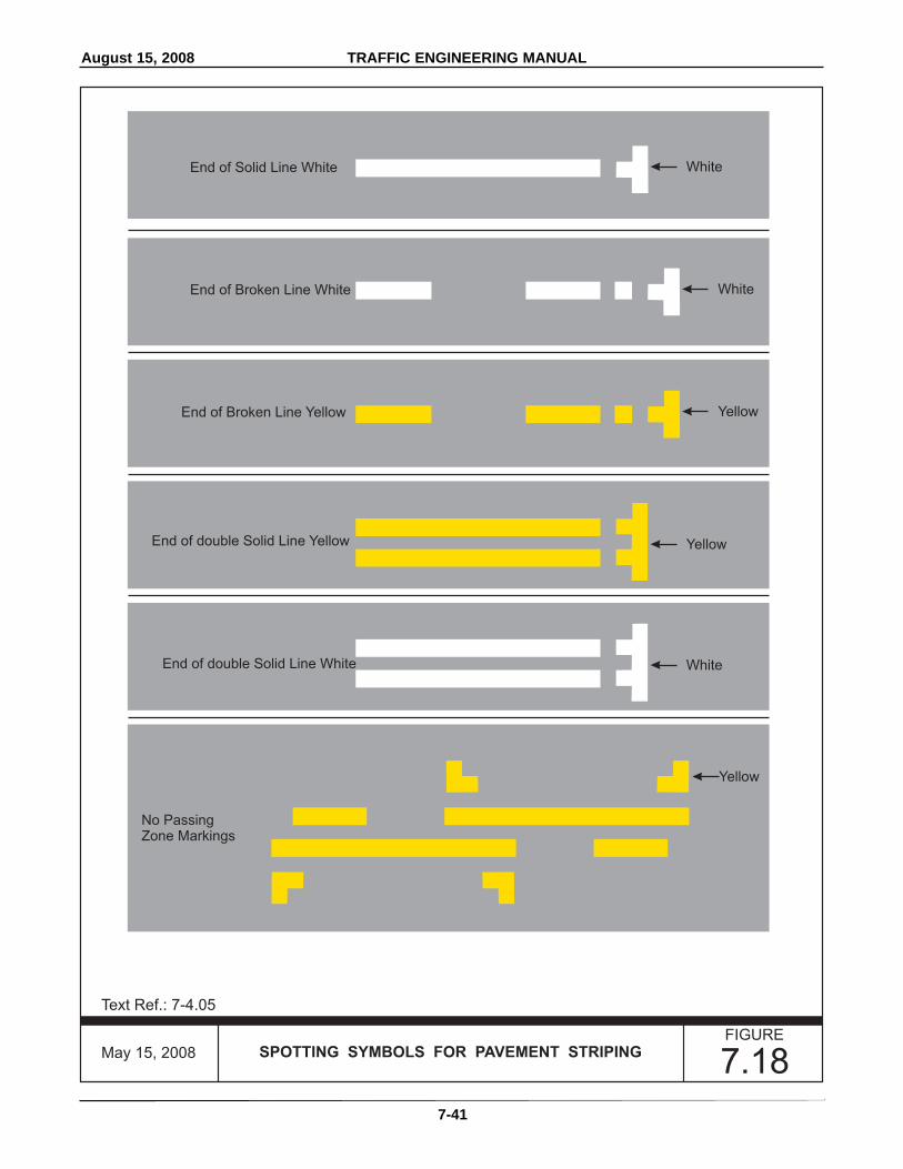
The trailing vehicle operator should mark to the right of the centerline and the leading vehicle to the left. Thetrailing vehicle marks will represent the beginning and end of the no-passing zone for vehicles traveling in thedirection of the study.
The lead vehicle marks will represent the no-passing zone for the opposite direction of travel. See Figure 7.18 forspotting symbols.
The two vehicles should then proceed forward with identical DMI readings until the driver of the trailing vehiclesees the top of the lead vehicle. Both vehicles are stopped and the trailing vehicle is moved forward to obtainidentical DMI readings. Then both vehicles should move forward 50 feet, and stop to determine if the target hasre-appeared. This "stepping" is repeated until the target re-appears. Both drivers should then stop and mark theroadway. The lead driver marks on the left of the centerline and the trailing driver marks on the right of thecenterline. See Sketch 1 below and Figure 7-16.
Sketch 1 - Establishing Marks for Identifying No Passing Zone Locations
First Set of Marks Second Set of Marks

August 15, 2008 TRAFFIC ENGINEERING MANUAL
7-12
It is possible for vehicles positioned in-between the study vehicles to become lost in depressions although thevehicles are spaced the minimum sight distance apart and the drivers may see each other. Reverse horizontal curvescan create similar situations. See Sketch 2 below.
Sketch 2 - How Obstructions and Depressions Cause Vehicle to Become “Lost”
The following procedure is suggested for handling these lost vehicle situations. The driver of the lead vehicleestimates where the low point of a depression is and stops there, after notifying the trailing vehicle of what processis being performed. The trailing vehicle then moves forward until the target on the lead vehicle is in sight. If it isnoted by the trailing driver that other on-coming vehicles continue to become lost, the trailing vehicle must moveforward to a point where the driver does not lose an on-coming car in the depressions. At this point, a spot shouldbe marked to the right of the centerline by the trailing vehicle's driver. With the trailing vehicle stopped, the leadvehicle then moves forward so it has a DMI reading identical to the trailing vehicle and marks a spot to the left ofthe centerline. The two vehicles are now synchronized and may proceed with the study. If traffic volumes are highenough, the trailing vehicle can use oncoming cars to spot depressions and sight in on both headlights instead ofthe target on the lead vehicle. The trailing driver would then radio this reading to the lead driver to re-synchronizethe vehicles.
Horizontal curves can be more challenging. Ideally, sight lines should be made from the wheel path nearest thecenterline or on the centerline. Drivers may have to exit their vehicles and use the height-of-eye paddles (SeeSketch 3). Multiple horizontal curves in a row or compound curves will probably have to be driven in bothdirections to verify accurate placement.
The minimum passing sight distance used during the study should be changed to accommodate changes in thespeed limit. This may require changing passing sight distances while in a no passing zone. If there is any doubt,the longer of the two distances should be used. It is advisable to drive these situations in both directions to confirmplacement.

October 31, 2009 TRAFFIC ENGINEERING MANUAL
7-13
Range finders will help in determining if zones should be connected. If at the end of a potential zone, the trailingoperator sees a stop sign ahead, the operator can target the stop sign and get a reading. If that reading is less thanthe distance in Chart 7-2 plus the gap distance shown in Chart 7-4, then a mark should not be made at the end ofthe zone until reaching the intersection. Similar range finding techniques can be used to assist in placement ofzones in advance of bridges, RR crossings, and medians. The use of temporary pavement tape for spotting markscan also be a time saver in challenging alignment where many gaps need to be connected. The tape can be easilypulled off the pavement without scarring or causing black paint erasure marks.
Before final no passing zones are marked on the pavement, minor adjustments may be made to survey data so thatthe marking of sight restrictions of short duration are either extended to 500 feet (0.095 mile) or disregardedaltogether. If extended, the addition shall be made to the beginning of the zone. Before a sight restriction of lessthan 500 feet is either installed or disregarded, close field examination shall be made, checking to see if the targetis completely out of sight for approximately 2 seconds at the prevailing speed. If the target vehicle does not gocompletely out of sight, the no-passing zone may be disregarded.
Sound judgment must be exercised by the No-Passing Zone crew leader, taking into consideration distancetraveled and time elapsed during the sight restriction and weighing these factors against the time which bothdrivers have to observe each other prior to reaching the sight obstruction. If doubt exists, the no-passingzone should be marked to a minimum of 500 feet.
Chart 7-1 shows a typical form that may be used to log the placement and type of no passing zones. This form isavailable in an excel spreadsheet from the OTST Pavement Marking Engineer.
7-4.04.03 Removal of Sight Obstructions
When minor maintenance activity can be performed to remove sight obstructions, a request explaining theobstruction shall be sent to the appropriate Maintenance Area for action. Requests for removal(s) of sightobstructions shall normally be limited to work needed to avoid extending a no passing zone.
Sketch 3 - Height-of-Eye Paddle
3' - 6"
1"x 4"peephole
Black
Bright colorreflectivesheeting

October 31, 2009 TRAFFIC ENGINEERING MANUAL
7-14
7-4.05 Standard Spotting Procedure
A standard practice of the department is to "spot" or mark guidelines for pavement markings and striping.
Traffic technician, survey crew or contractor does the spotting with a spray paint. Use the spotting system, shownin Figure 7.18 and described below, for all striping.
Match color of spot to the color of the stripe to be painted.
Generally spot as necessary to ensure proper placement of markings. Edgelines and no passing zone lines shouldnot be carried thru public access intersections. They should be carried thru driveways.
7-4.06 Special Markings
7-4.06.01 Pedestrian Crossings
An engineering study should be completed to determine the necessity of a pedestrian crosswalk. The study shouldinclude the following detailed information:
Geometrics
Motorist sight distance
Traffic volume data including truck traffic and turning movements
Daily pedestrian volume estimates
Observation of site characteristics that could divert driver attention from the crosswalk
Posted speed limit
Crash history
Sidewalks and pedestrian pathways
Performing engineering analysis on potential crosswalk locations should result in a more uniform application ofthe use of pedestrian crosswalks.
Not all sites warrant a pedestrian crosswalk or a crosswalk with additional treatments. The following are possibleoutcomes that may result from non-uniform application, misuse, or overuse of crosswalk safety treatments.
1. Noncompliance with traffic control devices.
In general, a motorist's decision on whether to comply with a traffic control device message is related to howreasonable the driver perceives the intended message conveyed by the device. If the message is not regardedas reasonable, the likelihood of noncompliance with the device increases.
2. Decrease in safety.
Studies have demonstrated that in some circumstances installing pedestrian crosswalks without some othertype of treatment such as signing, warning lights, etc. may not only be ineffective but could actually decreasethe safety of crossing the roadway.
3. Disregard of traffic control device.
Overuse of traffic control devices such as signs or striping can lead to a general disregard of the device.Drivers may start to ignore them creating a more hazardous situation.

August 15, 2008 TRAFFIC ENGINEERING MANUAL
7-15
Crosswalk Installation Guidelines
Mn/DOT has developed a flowchart (see Chart 7-8) to help decision makers determine whether or not a crosswalkis warranted. The following conditions must be met at all potential crosswalk locations:
Adequate stopping sight distance for motorists Minimal truck traffic Minimal vehicle turning movements Minimal driver distractions
The following sections support the criteria contained in the flowchart.
The following design options may be considered at locations that present a relatively high risk to pedestrians:
Pedestrian bridge or underpassPedestrian signal
The following design options may be considered at locations that present a relatively medium risk to pedestrians:
Modify existing lane configurationsRaised median (minimum width of four feet and length of eight feet)Curb extensionsPedestrian crossing islandAdvanced stop lines and associated signingParking restrictionsIncreased law enforcementModify and/or add lighting
Some Condition Yellow crossings may be determined sufficient without additional crosswalk enhancements.
Crossings that are identified as having a relatively low risk for pedestrians are those that typically require onlypavement markings. Signing may be included based on engineering analysis.
Crosswalk treatments should be selected to address a specific problem, such as crossings at multi-lane locationswhere multiple conflicts may be expected.
See also "School Crossings" section below.
Place pedestrian crosswalk lines as shown in Figure 7.19 and 7.20. If used, the words PED XING in white may beplaced on the approaching pavement lane or lanes for the benefit of approaching traffic. This pavement messageshould be placed near the PEDESTRIAN CROSSING (W11 2) sign.
In municipalities, crosswalks and pavement markings for school and pedestrian crossings are usually provided bylocal authorities. The district traffic engineer may provide expertise in the initial efforts by the municipality. Thedepartment usually does not provide crosswalks or pedestrian markings in unincorporated areas. However, if adefinite need exists, the department may install crosswalk and pavement markings.
Condition GreenCondition Green
Condition Yellow
Condition RedCondition Red

August 15, 2008 TRAFFIC ENGINEERING MANUAL
7-16
7-4.06.02 School Crossings
The following guidelines govern the provision of school markings:
1. School Adjacent to Highway
When a school building or its grounds are adjacent to a trunk highway, the School Advance Warning assembly(S1-1 with appropriate supplemental distance plaque) should be erected. If no crosswalk is provided, the word"SCHOOL" may be applied in white on the approaching traffic lane or lanes near the School AdvanceWarning assembly. The School Advance Warning assembly and "SCHOOL" pavement message should notbe used if the highway right-of-way is fenced and no access is provided directly to the highway.
2. Crosswalk
When a crosswalk is designated within a school zone, install the School Crosswalk Warning Assembly (S1-1with diagonal down arrow) as specified in the MN MUTCD, section 7B.9. The crosswalks may also bepainted and the words SCHOOL XING may be applied in white near the School Advance Warning assembly.
Sidewalks or hard-surface pedestrian paths with ADA compliant pedestrian ramps shall be present before thecrosswalks will be installed. It is also recommended to advise the school district to furnish crossing guardprotection at these locations to ensure safety.
3. Roadway Message
If a sight restriction exists, the advance warning message SCHOOL XING shall be applied along withappropriate advance warning signs required by the MN MUTCD, Section 4D-15.
In municipalities, crosswalks and pavement markings for school and pedestrian crossings are usually providedby local authorities. The district traffic engineer may provide expertise in the initial efforts by themunicipality. The department usually does not provide crosswalks or pedestrian markings in unincorporatedareas. However, if a definite need exists, the department may install crosswalk and pavement markings.
7-4.06.03 Railroad Crossing with Stopping Lane
All approaches to railroad grade crossings with a stopping lane in rural areas, except minor spurs, shall be markedas shown in Figure 7.14. The local road authority is responsible for marking all railroad crossings on theirroadways.
7-4.06.04 Stop Lines
Use stop lines to emphasize stopping location. Stop lines shall extend across all approach lanes. See Figure 7.22and guidelines below:
1. Stop Sign
It is preferable to place Stop Line in line with the STOP sign. However, if the STOP sign cannot be locatedexactly where vehicles are expected to stop, the stop line should be placed at the desired stopping point.
2. Rural Areas
Stop lines in rural locations shall be placed only where the district traffic engineer has determined a need forsuch control. A traffic control order shall be used.
3. Urban Areas
Stop lines in urban areas should be placed 4 feet in advance of and parallel to the nearest crosswalk line. Inthe absence of a marked crosswalk, the stop line should be placed at the desired stopping point. In no caseshall a stop line be placed more than 30 feet or less than 4 feet from the nearest edge of the intersecting curbline or edge of the thru traveled lane.

August 15, 2008 TRAFFIC ENGINEERING MANUAL
7-17
7-4.06.05 Stop Ahead or Signal Ahead
The STOP AHEAD or SIGNAL AHEAD messages shall be placed where a study by the district traffic engineerhas determined a need for this type of warning. A pavement message is usually placed at or shortly beyond the signgiving the same message and may be repeated wherever approach speeds are high or unusual alignment exists. Asolid yellow no-passing line shall be used with the STOP AHEAD or SIGNAL AHEAD pavement message (seeFigure 7.22).
7-4.06.06 Parking Space Markings
Parallel parking spaces, where used, are to be marked with white lines with desirable dimensions of 8 feet by 22to 26 feet (see MN MUTCD, Section 3B.18 and Figure 3B-8). Parking spaces in state rest areas should be stripedas shown in Figure 7.23. Municipal parking spaces are marked by local authorities.
7-4.06.07 Curb Markings
Use curb markings only to indicate parking is prohibited at all times. Other restrictions should be shown bystandard parking signs. Local authorities may paint curbs yellow under the conditions described in MinnesotaStatutes Section 169.34. Local authorities may also prohibit parking at other locations. Permission to restrictparking on trunk highways must be obtained from the appropriate district traffic engineer.
7-4.06.08 Markings for Speed Enforcement (Airplane Markings)
See Figure 7.24.
To determine appropriate pavement markings for State Patrol airplanes, each district traffic engineer should conferannually with the patrol captain and chief pilot to review existing zones. This review should identify any zoneswhich can be eliminated because they are not being used.
Use white stripes, with dimensions of 4 feet by 2 feet if in the traffic lane or on the centerline. Use white stripes 6feet by 2 feet for markings on the shoulder. The marking should extend 2 feet into the driving lane.
A zone should consist of a set of 5 markers and be placed on a straight roadway if possible. Zones should beseparated by 1/2 to 1 mile.
7-4.06.09 Preferential Lane Markings
1. Bus and Car Pool
See Figure 7.25 for an example of the application of "restricted lane" markers at a freeway on-ramp. The useof "restricted lane" markings shall be documented by a Traffic Control Order and approved by the StateTraffic Engineer.
7-4.06.10 Roundabout Intersections
The overall concept for roundabout marking is similar to general intersection marking. Typical pavement markingfor Roundabout Intersections consists of delineating the entries and marking the circulatory roadway on multi-laneRoundabout Intersections. This task is not easy and must be reviewed by an experienced roundabout designer andthe District traffic engineer.
1. Specifying Materials and Installation
Dotted extension lines and crosswalks near roundabout will deteriorate at an accelerated rate. It isrecommended that a durable pavement marking be used. This should be clearly spelled out in thespecifications and mentioned at the preconstruction conference.

August 15, 2008 TRAFFIC ENGINEERING MANUAL
7-18
2. Single Lane Roundabout Intersections
In general, single lane Roundabout Intersections need no lane arrows or circulatory roadway pavementmarking. Bike lane marking within the circulatory roadway is not permitted on any Roundabout Intersections.(See Figure 7.36)
3. Multi-Lane Roundabout Intersections
Contact the Office of Traffic, Safety and Operations for assistance in development of pavement marking plansfor a multi-lane roundabout.
4. Relationship with the MN MUTCD
The Minnesota Manual on Uniform Traffic Control Devices (MN MUTCD) governs the design and placementof signs and markings. The MN MUTCD follows the guidelines in the Federal MUTCD
5. Other Standards
Applicable local standards may also govern the design and placement of pavement markings as long as theydo not conflict with the MN MUTCD and Mn/DOT policies. Roundabout Intersections present a number ofnew pavement marking issues that are not addressed in the MN MUTCD or the FHWA Roundabout: “AnInformational Guide.” On connecting highways coordinate pavement marking with the district traffic officeand the local agency to maintain consistency on the facility. Contact the Office of Traffic, Safety andOperations for additional guidance.
6. Approach and Entry Pavement Markings
Approach and entry pavement markings consist of dotted edge line extension marking and optional yield lineand optional symbol markings. Consult the District Traffic Engineer for optional marking recommendations.
7. Approach Marking
Splitter islands will be marked in accordance with standard Mn/DOT guidelines for "Approach Markings forObstructions" MN MUTCD, Section 3B.19. Where pedestrian traffic is expected and signing is provided, thedesigner may provide crosswalk pavement markings.
The dotted edge line extension used to demarcate the entry approach from the circulatory roadway is 8-incheswide for single lane entries to the roundabout with a 3 ft line, 3 ft gap and located along the inscribed circle.Set the dotted edge line extension slightly back from the circulating roadway to prevent circulating trafficfrom scuffing the markings. Do not place pavement marking to demarcate the exit from the circulatoryroadway
Pavement word or symbol markings to supplement the signing and yield point marking may be desirable, consultwith the District Traffic Engineer for further guidance. These markings should conform to the standards given inMN MUTCD, Section 3B.19.
7-5.0 OBJECT MARKINGS
7-5.01 Purpose
Object markers are used to identify physical features located within or adjacent to the roadway such as trafficislands, road or street termination and freeway gore areas. Obstacles such as bridge piers and abutments that areclose to a traveled lane generally require additional warning techniques.

August 15, 2008 TRAFFIC ENGINEERING MANUAL
7-19
7-5.02 Types of Object Markers
For object marker types, color, and uses, consult the Mn/DOT Standard Signs Manual and the MN MUTCD.Additionally, Mn/DOT uses a Snowplow Marker (X4-5) which is not referenced in the MN MUTCD.
Information pertaining to materials, sheeting, and sign substrates can be found in the Minnesota StandardSpecifications for Construction, sections 2564 and 3352.
7-5.02.01 Snowplow Marker (X4-5)
This marker indicates to a snowplow operator the beginning and end of a guardrail installation. The snowplowmarker is shown in Chart 7-5 and Figure 7.26.
7-5.03 Applications and Guidelines
7-5.03.01 Bridges Abutments, Piers, and Rails
Bridge abutments, piers, and rails within the width of the approaching shoulders shall be marked with Type 3Object Markers (Clearance Marker X4-4). A typical application can be found in Figure 7.26.
7-5.03.02 Narrow Bridges/One Lane Bridges
A narrow bridge shall be defined as any of the following:
1. A bridge with a minimum driving surface width greater than 18 feet and less than the roadway approach width(not including shoulders).
2. A bridge where engineering judgment of approach grades, curvatures, number of trucks or otherconsiderations justifies a narrow bridge classification.
Narrow bridges should be marked and delineated as shown in Figure 7.27.
A one-lane bridge is defined as any bridge having a clear opening width of 18 feet or less. One-lane bridges shallbe marked and delineated as shown in Figure 7.28.
7-5.03.03 Cattle Passes/Large Culverts
Cattle passes and larger culverts that meet one of the following descriptions are subject to the provisions of thissubsection:
1. Headwalls are present and are not protected by guardrail, subject to engineering judgement
2. Minimum width of 42 inches and a maximum width of 20 feet. Large culverts 20 feet or wider may be treatedas a bridge, subject to engineering judgement.
3. Any culvert with an end or opening that is within 8 feet of the outside edge of the shoulder. This 8 footdistance was selected because it may allow a motorist to pull off of a narrow shouldered roadway if otherconditions permit.
4. Other structures as determined by the district traffic engineer.

October 31, 2009 TRAFFIC ENGINEERING MANUAL
7-20
All cattle passes and larger culverts meeting the above criteria should be marked with Type 2 object markers asdescribed in Section 3C.3 of the MN MUTCD and the following:
1. The Type 2 Marker used shall be a 6” x 12” marker constructed of 0.062-inch aluminum or other lightweightmaterial such as fiberglass or flexible urethane sheeting. The marker shall use fluorescent yellow prismaticretroreflective sheeting of a type compatible with the base material.
2. On special flexible post designs that cannot accommodate the 6" x 12" marker, a 3" x 12" marker may be used.
3. Two markers shall be mounted back-to-back on a flexible post or 2-pound steel post. A flexible post ispreferred due to its resistance to being knocked down by snowplows and farm equipment. Additionally, itprovides better daytime visibility.
4. The two-way marker assembly shall be installed on the near right side immediately in front of the structureas shown in Figure 7.29.
The typical marking of cattle passes and large culverts not protected by guardrail are shown in Figure 7.29.
7-5.03.04 Guardrail
The approach end of plate beam guardrail installations should be marked with a striped object marker sized to fitthe end terminal of the guardrail. The alternating black and reflective yellow stripes shall slope downward at a 45degree angle toward the side on which traffic is to pass. The marker shall be made of fluorescent yellow prismaticretroreflective sheeting.
On guardrail installations with flat end treatments, the object marker shall fit within the recessed area. Oninstallations with round end treatments, the object marker shall wrap around the circular end treatment and shallbe mounted so that the top of the marker is even with the top of the circular end treatment.
Both ends of all guardrails shall be marked with the Snowplow Marker (X4-5) as shown in Figure 7.26.
7-5.03.05 Islands and Interchange Gores
A typical application of the placement of object markers on island or interchange gores can be found in Chart 7-5and Figures 7.26 and 7.30.
7-5.03.06 End of Roadway
A typical placement of markings for a roadway that ends with no alternative vehicular path is shown in Figure 7.26.
7-5.03.07 Driveway Reflectors
A property owner may mark each side of a driveway entrance with reflectors. Blue colored reflectors are preferredalthough white (colorless) may be used. Place each reflector on its own structure (not to exceed a 1.0 pound post),not more than 5 feet above the ground, and at least 12 feet from the outside edge of the shoulder to preventsnowplow damage.
Red or yellow reflectors should not be used since they can be easily confused with motor vehicle tail lights.Mn/DOT forces may remove existing reflectors if they obstruct or interfere with the effectiveness of any trafficcontrol device (Reference: MS169.07).
7-5.03.08 Other Objects
Objects located within the clear zone should be marked with the proper object marker. The clear zone should bedetermined as stated in Chapter 4 of the Road Design Manual.

August 15, 2008 TRAFFIC ENGINEERING MANUAL
7-21
7-6.0 DELINEATION
7-6.01 Types and Materials
For delineator types and colors, consult the Mn/DOT Standard Signs Manual, the MN MUTCD, and Figure 7.30and Chart 7-6 of this manual.
Information pertaining to materials, sheeting, and sign substrates can be found in the Minnesota StandardSpecifications for Construction, sections 2564 and 3352.
7-6.02 Delineator Location
The details of height and location of delineators are shown in Figure 7.30 and stated below.
7-6.02.01 Delineator Height and Lateral Placement
When used, install delineators so that the bottom of the delineator is 4 feet above the surface of the nearest trafficlane. Install delineators between 2 feet and 8 feet outside the roadway or pavement edge. On roadways withshoulders, delineators should be installed 6 feet outside the shoulder break. Along curbed sections of roadways,delineators shall be placed not less than 2 feet, nor more than 5 feet, from the curb face.
7-6.02.02 Delineator Spacing
Delineators should be placed at a constant distance from the edge of the roadway except where a guardrail or otherobstruction intrudes into the space between the pavement edge and the extension of the line of delineators. Thedelineators should then be in line with or inside the innermost edge of the obstruction. A typical delineatorinstallation is shown in the MN MUTCD, Section 3D.4, and Figure 7-30 of this manual.
A simple method for field personnel to determine the degree of curve or the radius of a curve is shown in Chart 7-7.
1. Along Horizontal Curves
When applied on the approaches to and throughout horizontal curves, spacing should permit severaldelineators to always be visible along the curve ahead of the driver. Figure 3D-1 and Table 3D-1 of the MNMUTCD show the recommended spacing for delineators along horizontal curves. A typical layout fordelineator spacing on horizontal curves is shown in Chart 7-7.
2. Along Vertical Curves
When applied on crest vertical curves, the spacing should permit a minimum of three delineators to be visiblefrom all points along the centerline of the curve at an eye level of 4 feet above the pavement.
3. Along Tangent
When used, delineators should be spaced 0.1 mile apart along the through roadway, except along accelerationand deceleration lanes where the spacing should be as indicated in Section 3D.4 of the MN MUTCD.
7-6.02.03 Divided-Highway Crossovers
Delineation of divided-highway crossovers is shown in Figure 7.32.
7-6.02.04 Interchanges
Delineation of cloverleaf and diamond interchanges is shown in Figures 7.33 through 7.35.

August 15, 2008 TRAFFIC ENGINEERING MANUAL
7-22
7-6.02.05 Guardrail
Three cable guardrail shall be delineated as shown in the current version of Mn/DOT Standard Plate Nos. 8330and 8331. The color of the reflective sheeting shall match the color of the adjacent edge line.
Plate-beam guardrail delineation is under investigation.
7-6.03 Deer Reflectors
Each district may make the decision to remove existing deer reflectors based on any of the following conditions:
1. The existing installations are more than six years old and there is no intent of maintaining them due toreplacement costs (lack of maintenance funds), complicated installation procedures, and a lack of staff.
2. The existing installations are a problem for maintenance activities (their lateral placement causes mowing andsnow removal problems).
3. Written documentation indicates that either the number of deer kills has not been significantly reduced or thenumber of deer kills has actually increased.
7-7.0 REFERENCES1. Minnesota Department of Transportation, Minnesota, Manual on Uniform Traffic Control Devices, current
edition.
2. American Association of State Highway Officials, A Policy on Geometric Design of Rural Highways, currentedition.
3. State of Minnesota, Minnesota Statutes.
4. Minnesota Department of Transportation, Standard Signs Summary, current edition.
5. Minnesota Department of Transportation, Road Design Manual, current edition.
6. Mn/DOT Bikeway Facility Design Manual, current edition.
www.dot.state.mn.us/bike/bikewaysdesignmanual.html

August 15, 2008 TRAFFIC ENGINEERING MANUAL
7-23
Text Ref.: 7-4.03.01
FIGURETWO-LANE, TWO-WAY ROADWAY
PAVEMENT MARKING DETAILS 7.1
4 in.
2 in. 1 in.+
4 in. SolidLine White
4 in. SolidLine White4 in. Solid or
Broken Line Yellow
2 in. 1 in.+
12 ft. Lane 12 ft. Lane
LC
SECTION B-B( 24 ft. roadway )
TypicalShoulder
TypicalShoulder
40 ft.
50 ft. Cycle
4 in. Broken Line Yellow
4 in. Solid Line White
NOTE: Do not place longitudinal pavementmarking lines on the roadway joints.
4 in. Solid Line White
10 ft.
4 in. Broken Line Yellow2 in. 1 in. from C+ L
CLB
B
4 in. Solid Line Yellow No Passing Line 1
1 Contact traffic engineer for No Passing Survey
May 15, 2008

August 15, 2008 TRAFFIC ENGINEERING MANUAL
7-24
Text Ref.: 7-4.03.02
FIGUREMULTI-LANE UNDIVIDED ROADWAY
PAVEMENT MARKING DETAILS 7.2
12 ft. Lane 12 ft. Lane 12 ft. Lane 12 ft. Lane
50 ft. Cycle
4 in. Solid Line Yellow 4 in. apart
4 in. Solid Line White2 in. 1 in. from edge ofPavement to edge of stripe.
+
40 ft.
10 ft.
4 in. BrokenLine White
4 in. BrokenLine White
Shoulder
Shoulder
Shoulder
Shoulder
4 in. SolidLine White
4 in. SolidLine White
2 in. 1 in.+ 2 in. 1 in.+4 in. 1 in.+
2 in. 1 in.+ 2 in. 1 in.+
4 in. SolidLine Yellow
4 in. SolidLine Yellow
CL CLCL
SECTION A-A
A
A
NOTE: Do not place longitudinal PavementMarking Lines on the roadway joints.
May 15, 2008

August 15, 2008 TRAFFIC ENGINEERING MANUAL
7-25
Text Ref.: 7-4.03.03
FIGURETWO-WAY LEFT TURN LANE
PAVEMENT MARKING DETAILS 7.3
4 in. 4 in.
4 in. Broken Line Yellow
SECTION C-C
Lane Width4 in. SolidLine Yellow
4 in. SolidLine Yellow
4 in. Broken Line White
4 in. Broken Line Yellow 4 in. SolidLine Yellow
8 ft. - 16 ft.
C
C
Min
or
Cro
ss
Stre
et
Majo
rC
ross
Stre
et
50 ft.50 ft.
Minimum
50 ft.200 ft.
Maximum*200 ft.
Maximum*
100 ft. Minimum
**
** See “TYPICAL MESSAGE PLACEMENTFOR TURN LANES” for the number andplacement of turn arrows and how tointroduce this lane -- Figure 7.9
* These distances should be equal. The Pavement Arrowsare placed to show the operation and do not have toline up with any of the driveways.
4 in. Solid Line White
May 15, 2008

October 31, 2009 TRAFFIC ENGINEERING MANUAL
7-26
Text Ref.: 7-4.03.01 (2a)
FIGURE
PASSING LANE SECTION PAVEMENT MARKINGS 7.4
NOTE:
1. The same treatment is used for both approaches.2. The lane skip striping shall end approximately
50 feet beyond the Lane Reduction sign.3. More details on signing can be found in Chapter 6.
200 ft.
LAN E EN DS
M ERG E
L E FT
AA BB
500 ft. Minimum(see Chart 7-4)
AA BB
4 in. SolidLine White
4 in. Solid Line Yellow
45 , at 20 ft. Spacing(see Figure 7.9)
o
4 in. BrokenLine Yellow
4 in. Broken Line White 4 in. Broken Line Yellow
October 31, 2008

August 15, 2008 TRAFFIC ENGINEERING MANUAL
7-27
Text Ref.: 7-4.03.06
FIGURE
MAJOR INTERSECTION PAVEMENT MARKINGS 7.5A
**
***
***
**4 in. SolidLine Yellow
**4 in. SolidLine Yellow
4 in. BrokenLine Yellow
2 - TWO LANE ROADS
NOTE: Stop Line Widthshall be 24 in.
***
***
Optional
see Charts 7-2 and 7-4
from Curb Line or near edge of the thru traveled lane.
Solid WhiteStop Line
4 ft. Minimum
4 ft. Minimum
STOP
STOP
May 15, 2008

August 15, 2008 TRAFFIC ENGINEERING MANUAL
7-28
Text Ref.: 7-4.03.06
FIGURE
MAJOR INTERSECTION PAVEMENT MARKINGS 7.5B
*
*
***
***
**
**
*
4 in. Solid Line Yellow
4 in. Solid Line Yellow
4 in. BrokenLine Yellow
4 in. BrokenLine Yellow
Solid White Stop Line should beplaced at the stopping point.
Solid White Stop Line should beplaced at the stopping point.
LARGE RADIUS INTERSECTION
LARGE RADIUS INTERSECTION
NOTE: Pavement Messagesare 8 ft. White Letters
NOTE: Pavement Messagesare 8 ft. White Letters
***
***
Optional
see Charts 7-2 and 7-4
from Curb Line or near edge of the thru traveled lane.
4 ft. Minimum
4 ft. Minimum
50 ft. Maximum fromedge of shoulder
50 ft. Maximum fromedge of shoulder
STOP
STOP
DO
NOT
PASS
May 15, 2008
October 31, 2009 TRAFFIC ENGINEERING MANUAL
7-29
Text Ref.: 7-4.05.07
FIGUREOctober 31, 2009
RAMP AND THROUGH LANEPAVEMENT MARKINGS 7.6
SEE DESIGN C
SEE DESIGN C
Shoulder Area
SEE DESIGN C
SEE DESIGN A
SEE DESIGN A
SEE DESIGN B
SEE DESIGN D
SEE DESIGN E
PARALLEL ACCELERATION LANE
EXIT RAMP MARKINGS
TAPERED ACCELERATION LANE
THROUGH LANE MARKINGS
RAMP MARKINGS
8 in. Solid Line White (Channelizing)
8 in. Solid Line White (Channelizing)
8 in. Solid Line White (Channelizing)
4 in. Solid Line White
4 in. Broken Line White
4 in. Broken Line White
4 in. BrokenLine White
2 in. 1 in.+
BituminousShoulder
A
ABituminousShoulder
4 in. Solid Line White
4 in. Solid Line White4 in. Solid Line White
4 in. SolidLine White
4 in. Broken Line White for one-halfthe length of full width acceleration lane.
4 in. Solid Line Yellow 2 in. 1 in.from edge of pavement toedge of stripe
+
4 in. Solid Line Yellow fromedge of pavement to edge of stripe
4 in. Solid Line Yellow2 in. 1 in. fromedge of pavementto edge of stripe
+
4 in. Solid Line Yellow2 in. 1 in.” from edge ofpavement to edge of stripe
+
50 ft. Cycle
40 ft.10 ft.
Begin at 24 ft. width
4 in. Solid Line White 2 in. 1 in.from edge of pavement to edge of stripe
+
4 in. Solid Line White 2 in. 1 in.from edge of pavement to edge of stripe
+
4 in. Solid Line White 2 in. 1 in.from edge of pavement to edge of stripe
+
4 in. Solid Line White 2 in. 1 in. fromedge of pavement to edge of stripe
+
DESIGN A DESIGN B
Edge ofMainline
Edge ofMainline
Edge of ramp
Edge ofRamp
8 in.8 in. SolidLine White
4 in.
8 in. SolidLine White
8in
.
6 ft.
BituminousShoulder
BituminousShoulder
Median,Drivers Left
SECTION A-A(THREE LANES)
12 ft. Lane 12 ft. Lane12 ft. Lane 4 in. SolidLine White
4 in BrokenLine White
4 in BrokenLine White
2 in. 1 in.+2 in. 1 in.+2 in. 1 in.+2 in. 1 in.+
4 in. SolidLine Yellow
DESIGN C
URBAN
DESIGN C
RURAL
Markings adjacentto Design D curb
Shoulder
30 in.4 in Stripe
4 in. Stripe
2 in. 1 in.+
2 in. 1in.+2 in. 1in.+
2 in. 1in.+2 in. 1in.+
DESIGN D
RURAL
2 in. 1in.+
2 in. 1in.+
Edge ofMainline
Edge ofRamp
4 in. SolidLine Yellow
4 in. SolidLine White 8 in. Solid
Line White
8 in. SolidLine White
DESIGN E
RURAL
2 in. 1in.+
2 in. 1in.+
4 in. SolidLine White
8 in. Solid
Line White4 in. Solid
Line Yellow
Edge ofRamp
Edge ofMainline
August 15, 2008 TRAFFIC ENGINEERING MANUAL
7-30
Text Ref.: 7-4.03.07
FIGUREEXIT RAMP ON CURVED ROADWAY
PAVEMENT MARKINGS 7.7
4 in. Solid Line White
4 in. Solid Line Yellow
4 in. Solid Line White
4 in. Solid Line White
8 in. SolidLine White
4 in. Solid Line Yellow
4 in. Broken Line White
ExitRamp
ExitRamp
Dotted white extensionof edge lineLength: 3 feetSpacing: 12 feetWidth: 8 inches
May 15, 2008

August 15, 2008 TRAFFIC ENGINEERING MANUAL
7-31

August 15, 2008 TRAFFIC ENGINEERING MANUAL
7-32

August 15, 2008 TRAFFIC ENGINEERING MANUAL
7-33
12 ft.Turn Lane
12 ft .Lane
TYPICAL LEFT TURN LANE TYPICAL RIGHT TURN LANE
Typical markings forLeft Turn Islands
TYPICAL MESSAGE PLACEMENTFOR TURN LANES
4 in. solidLine White
4 in. SolidLine White
12 ft. Lane 12 ft.Turn Lane
4 in. Line 4 in. Line
4 in.Maximum
4 in.Maximum
4 in. Solid Line Yellow
200 ft.or less
over 200 ft.
30-80 ft.
50 ft.
50 ft.
8 ft.Arrows
Arrow atMidpoint
4 in. Solid Line White
Two 4 in. SolidLines Yellow
20 ft.
45
24 in. SolidLine Yellow
500 ft. SolidLine Yellow
See Chart 7-4
At speeds over 40 mph thecrosshatch spacing may beincreased to 30 ft. betweencrosshatch lines.
At speeds less than 40 mphthe width of the crosshatchline may be reduced to 12 in.
c c
2 in. 1 in.Maximum
+2 in. 1 in.
Maximum+2 in. 1 in.
Maximum+
Text Ref.: 7-4.03.09
FIGURETURN LANE AND LEFT TURN ISLAND
PAVEMENT MARKINGS 7.9
20 ft.
May 15, 2008

October 31, 2009 TRAFFIC ENGINEERING MANUAL
7-34
Text Ref.: 7-4.03.10
FIGUREBYPASS LANE
PAVEMENT MARKINGS 7.10
50 ft.
50 ft.
50 ft.
25 ft.
25 ft.
50 ft.
50 ft.
End8 in. DottedLine White
Begin8 in. DottedLine White
8 in. DottedLine White
8 in. DottedLine White
8 in. DottedLine White
Begin4 in. SolidLine White
Begin8 in. DottedLine White
4 in. SolidLine White
4 in. SolidLine White
4 in. SolidLine White
4 in. SolidLine White
4 in. SolidLine White
4 in. BrokenLine Yellow
4 in. BrokenLine Yellow
8 in. DottedLine White
Begin8in. DottedLine White
4 in. BrokenLine Yellow
4 in. BrokenLine Yellow
Note:1. No Passing Zones at intersections shall be striped for 500 feet on both
sides of the intersection if it is located within the city limits. No PassingZones at intersections shall be striped if located within any establishedNo Passing Zone. No Passing Zone striping is optional at the discretionof the district traffic engineer for rural intersections. See Chart 7-4.
2. See Figure 6.17 for signing.
See Figure 7.9 for the typical message placement of turn arrows.*
*
**
**
**
**
3 foot long line with a 12 foot gap.
October 31, 2009

August 15, 2008 TRAFFIC ENGINEERING MANUAL
7-35
Text Ref.: 7-4.03.12
FIGUREDIVIDED ROADWAY TRANSITION
PAVEMENT MARKINGS 7.11
4 in. Broken Line Yellow
4 in. Solid line white
4 in. DoubleSolid Line Yellow
4 in. SolidLine Yellow
4 in. SolidLine White
4” Broken Line White
1:70Taper
1:70Taper
500 ft. SolidLine Yellow
500 ft. SolidLine Yellow
14 ft. 100 ft.-200 ft.
200 ft. 200 ft.
100 ft.-200 ft.14 ft.
12 ft.12 ft.
Yellow Delineation
24 in. Solid Line Yellow
45 , at 20 ft. spacing(See Figure 7.9)
O
White Delineation
**
* See Chart 7-4.
May 15, 2008

August 15, 2008 TRAFFIC ENGINEERING MANUAL
7-36

August 15, 2008 TRAFFIC ENGINEERING MANUAL
7-37

August 15, 2008 TRAFFIC ENGINEERING MANUAL
7-38
Text Ref.: 7-4.03.14 and 7-4.06.03
FIGURERAILROAD CROSSINGS WITH TRUCK STOPPING LANE
PAVEMENT MARKINGS 7.14
R R
R R
STO P P I N G
T R U CK
LAN E
W10-1
W9-2
W10-1
W14-3
R4-X4
4 in. SolidLine White
4 in. Solid Line Yellow(see Chart 7-4)
4 in. Solid Line White
8 in. Dotted Line White3 ft. long line with a 12 ft. gap.
Without Gate Arm -- 15 ft. fromnearest rail
With Gate Arm -- 5 ft. fromgate arm
50 ft.
2 ft.
2 ft.
50 ft. Minimum
Optional
1:15 Taper
500 ft.
1:15 Taper
R R
RR
Use the same signingand marking for theopposite direction.
LAN E EN DS
M ERG E
L E FT
R R
W10-1
60 ft.
24 ft.
20 ft.
6ft.-6in.
6 ft.
18 in.
2 ft.
2 ft.
3 ft.
16 ft.
16 ft.
R R
May 15, 2008

October 31, 2009 TRAFFIC ENGINEERING MANUAL
7-39
Text Ref.: 7-4.03.15
FIGUREOctober 31, 2009
FREE RIGHT TURN LANEPAVEMENT MARKINGS 7.15
4 in. Solid Line White
4 in. Solid Line White
4 in. Solid Line WhiteYIELD CONDITION
ACCELERATION LANE CONDITION
STOP CONDITION
4 in. Solid Line Yellow
4 in. Solid Line White4 in.
Edge ofMainline
Edge ofRamp
Begin 8 in. SolidLine White
DESIGN B
End Skip at Edgeof Thru lane
8 in. Dotted Line White3 ft. Long line with a 12 ft. Gap
DESIGN B
6 in.
8 in.
2 in. 1 in.+

August 15, 2008 TRAFFIC ENGINEERING MANUAL
7-40
Text Ref.: 7-4.04.02
FIGURE
NO PASSING ZONE PROFILES 7.16
a, a’ Begin no passing zone
Sight distance becomes less than minimum
measured between points 1.07 m (3.5 ft)
above pavement
a, a’ Begin no passing zone
Sight distance becomes less than minimum
measured between points 1.07 m (3.5 ft)
above pavement
b, b’ End no passing zone
Sight distance again exceeds minimum
b, b’ End no passing zone
Sight distance again exceeds minimum
aNo-passing zone, a to b
(indirection indicated)
No-passing zone, a to b
(in direction indicated)
Pavement profilePavement profile
Line of sight Line of sight
Minimum passing sight
distance for 85th percentile,
posted, or statutory speed
Minimum
passing sight
distance for 85thpercentile
,
posted, or statutoryspeed
b’ b
a’
1.07m (3.5 ft)
1.07m(3.5 ft)
1.07m (3.5 ft)
a - No-passing zone at VERTICAL CURVE
NOTE: No-passing zones in opposite directions may or may not overlap,depending on alignment.
NOTE: No-passing zones in opposite directions may or may not overlap,depending on alignment.
b’
b - No-passing zone at HORIZONTAL CURVE
Minimum passing sight
distance for 85th percentile,
posted, or statutory speed
Minimum passing sightdistance for 85th percentile,posted, or statutory speed
Line of sight
a’
No-passing zone, a” to b’
(in direction indicated
a
b
No-pass
ing
zone, a
tob
(indire
ctio
nin
dicate
d)
Profile View
Plan View
May 15, 2008
August 15, 2008 TRAFFIC ENGINEERING MANUAL
7-41
Text Ref.: 7-4.05
FIGURESPOTTING SYMBOLS FOR PAVEMENT STRIPING 7.18
WhiteEnd of Solid Line White
WhiteEnd of Broken Line White
YellowEnd of Broken Line Yellow
YellowEnd of double Solid Line Yellow
White
Yellow
End of double Solid Line White
No PassingZone Markings
May 15, 2008

August 15, 2008 TRAFFIC ENGINEERING MANUAL
7-42
Text Ref.: 7-4.06.01
FIGUREPEDESTRIAN CROSSWALK MARKINGS 7.19
6 ft. Min.24 in.
Building orConstruction
8 ft. Letters
Optional
Optional
Optional
Optional
100 ft.
40 ft.
NOTES:1. Pavement messages
are optional.2. Engineering judgement should
be used to determine whetherthey are necessary.
3. 6’ letters may be used ifapproach speeds are low.
4. See Figure 6.21 in Chapter 6 forappropriate signing.
AHEADx
PostedSpeedLimit(mph)
3035404550556065
Minimum distanceof Pavement Marking
from Intersection(feet)
75125200275350450525625
May 15, 2008

August 15, 2008 TRAFFIC ENGINEERING MANUAL
7-43
Text Ref.: 7-4.06.01
FIGUREPEDESTRIAN CROSSWALK MARKINGS -
CONTINENTAL BLOCK DESIGN 7.20
L
L
S
W
6 ft. Minimum
1.5 ft Minimum unstriped distance
NOTES: 1. Painted areas to be centered on centerline and lane lines.2. A minimum of 1.5 feet clear distance shall be left adjacent
to the curb. If the last painted area falls into this distance,it must be omitted.
3. On two-lane, two-way streets, use the spacing shown for a11 foot inside lane.
4. For divided roadways, adjustments in spacing of the blocksshould be made in the median so that the blocks are maintainedin their proper location across the traveled portion of the roadway.
5. At skewed crosswalks, the blocks are to remain parallel to thelane lines as shown.
6. The blocks shall be placed so that they are not located in the wheelpath of the vehicles.
(L)WIDTH OF
INSIDE LANE
(W)WIDTH OF
PAINTED AREA
(S)WIDTH OF
SPACE
9 feet
10 feet
11 feet
12 feet
13 feet
2.0 feet
2.5 feet
2.5 feet
3.0 feet
3.0 feet
2.5 feet
2.5 feet
3.0 feet
3.0 feet
3.5 feet
May 15, 2008

August 15, 2008 TRAFFIC ENGINEERING MANUAL
7-44
Text Ref.: 7-4.06.02
FIGURESCHOOL ZONE MARKINGS -
UNSIGNALIZED INTERSECTIONS 7.21
For optional crosswalk designsee Figure 7.20
4 in. SolidLine Yellow
4 in. SolidLine Yellow
S2-P2
S1-1
S1-1 W16-9p
W16-9p
S1-1
NOTE:Pavement messages
are optional
Urb
an
Are
a(low
speed
-250
ft.
Rura
l Are
a-
750f t.
Urb
an
Are
a(low
speed
-250
f t.
Rura
lAre
a-
750
f t.
SC
HO
OL
SC
HO
OL
OP
EN
FIE
LD
* 8 ft.Letters * 8 ft. LettersSCH OO L SCH OO L
X I N G
White Blocks
White Blocks
32
’
6 ft. Letters may be used if theapproach speeds are low.
See Charts 7-2 and 7-4 for length ofNo Passing Zone line
For
dis
tance,see
the
MN
MU
TC
D,S
ec.7B
-9.
For
dis
tance,see
the
MN
MU
TC
D,S
ec.7B
-9.
AH EAD
AH EAD
*
**
**
**
May 15, 2008

August 15, 2008 TRAFFIC ENGINEERING MANUAL
7-45
Text Ref.: 7-4.06.04
FIGURESTOP AHEAD & STOP LINE
SPAVEMENT MARKING 7.22
24 in. Solid Line White
4 in. Solid Line Yellow (see Charts 7-2 and 7-4)
4 in. Broken Line Yellow
4 in. Solid Line White
40 ft.
8 ft.Letters
100 ft.
W3-1a
See Chapter 6 forsign placement
STO P
AH EAD
NOTES:
1. Do not install a STOP AHEAD pavement message if the intersection has adequate lighting.
2. Install only one set of STOP AHEAD pavement messages. If a Stop Ahead sign needs to beinstalled more than 1000 feet from the STOP sign, contact the district traffic engineer todetermine if, and where, a second set of STOP AHEAD pavement messages should beinstalled.
3. The stop line should ordinarily be placed 4 feet in advance of and parallel to the nearestcrosswalk line. In the absence of a marked crosswalk, the stop line should be placed at thedesired stopping point, and in no case no more than 30 feet or less than four feet from thenearest edge of the intersecting curb line or the near edge of the thru lane.
If a stop line is used in conjunction with a stop sign, it should ordinarily be placed in line with thestop sign. However, if the sign cannot be located exactly where vehicles are expected to stop,the stop line should be placed at the stopping point.
May 15, 2008

August 15, 2008 TRAFFIC ENGINEERING MANUAL
7-46
Text Ref.: 7-4.06.06
FIGUREPARKING AREA PAVEMENT MARKINGS
DISABLED PARKING DETAILS 7.23A
Sidewalk
RampRamp
AlternateLocation
4 in. Solid Line White
4 in. Solid Line White
International Symbol ofAccessibility (optional)see Detail A
International Symbol ofAccessibility (optional)see Detail A
4 in. Solid Line White Border
4 in. Solid Line White Border
4 in. Solid Line White Diagonals3 ft. Center-to-Center
4 in. Solid Line White Diagonals3 ft. Center-to-Center
12 in. Solid White Lettering (optional)
12 in. Solid White Lettering (optional)
8 ft.minimum
8 ft.minimum
8 ft.minimum
8 ft.minimum
8 ft.minimum
10 ft. (12 ft.)
Standard Stall
centered
centered
Alternate Locations
PAR K I N G
VEH I C L E I D
R EQ U I R E D
U P TO $200 F I N E
FO R V I O LAT I O N
PAR K I N G
VEH I C L E I D
R EQ U I R E D
U P TO $200 F I N E
FO R V I O LAT I O N
PAR K I N G
N O
PAR K I N G
N O
SINGLE PARKING STALL
DOUBLE PARKING STALL
18
ft.m
inim
um
18
ft.m
inim
um
6in
.ty
pic
al
6in
.ty
pic
al
Curb Ramp
May 15, 2008

August 15, 2008 TRAFFIC ENGINEERING MANUAL
7-47
Text Ref.: 7-4.06.06
FIGUREPARKING AREA PAVEMENT MARKINGS
DISABLED PARKING DETAILS 7.23B
4 in. Solid Line White
International Symbol ofAccessibility (optional)see Detail A
4 in. Solid Line White Border
4 in. Solid Line White Diagonals3 ft. Center-to-Center
12 in. Solid White Lettering (optional)
PAR K I N G
VEH I C L E I D
R EQ U I R E D
U P TO $200 F I N E
FO R V I O LAT I O N
4 in. SolidLine White
36 in.
40 in.
International Symbolof Accessibility Markingfor accessible parking
space or stall
Sidewalk SidewalkRamp Ramp
PARKI NG
NO
DIAGONAL DOUBLE PARKING STALLS
DETAIL A
Retaining curb if necessary
8ft.
minim
um8
ft.
minim
um8
ft.
minim
um
cent
ered18
ft.m
inim
um
6in. typical
Total number ofparking spaces or stalls
Greater than 1000
Table A
20 plus 1 for each 100 orfraction thereof over 1000
1 - 25
26 - 50
51 - 75
76 - 100
101 - 150
151 - 200
201 - 300
301 - 400
401 - 500
501 - 1000
1
2
3
4
5
6
7
8
9
2 percent of total
Minimum number of disabledaccessible parking spaces or stalls
May 15, 2008
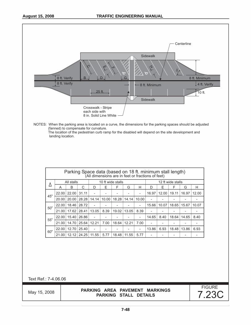
August 15, 2008 TRAFFIC ENGINEERING MANUAL
7-48
Text Ref.: 7-4.06.06
FIGUREPARKING AREA PAVEMENT MARKINGS
PARKING STALL DETAILS 7.23C
All stalls 10 ft wide stalls 12 ft wide stalls
Parking Space data (based on 18 ft. minimum stall length)(All dimensions are in feet or fractions of feet)
A
22.00
20.00
22.00
21.00
22.00
21.00
22.00
21.00
45
50
55
60
o
o
o
o
B
22.00
20.00
18.46
17.62
15.40
14.70
12.70
12.12
C
31.11
28.28
28.72
28.41
26.86
25.64
25.40
24.25
D
-
14.14
-
13.05
-
12.21
-
11.55
E
-
10.00
-
8.39
-
7.00
-
5.77
F
-
18.28
-
19.02
-
18.64
-
18.48
G
-
14.14
-
13.05
-
12.21
-
11.55
H
-
10.00
-
8.39
-
7.00
-
5.77
D
16.97
-
15.66
-
14.65
-
13.86
-
E
12.00
-
10.07
-
8.40
-
6.93
-
F
19.11
-
18.65
-
18.64
-
18.48
-
G
16.97
-
15.67
-
14.65
-
13.86
-
H
12.00
-
10.07
-
8.40
-
6.93
-
Sidewalk
SidewalkHFEC
B8 ft. Verify
8 ft. Verify
25 ft.
D G
8 ft. Minimum 4 ft. Verify
10 ft.
8 ft. Minimum
Centerline
Crosswalk - Stripeeach side with8 in. Solid Line White
NOTES: When the parking area is located on a curve, the dimensions for the parking spaces should be adjusted(fanned) to compensate for curvature.The location of the pedestrian curb ramp for the disabled will depend on the site development andlanding location.
May 15, 2008

August 15, 2008 TRAFFIC ENGINEERING MANUAL
7-49
Text Ref.: 7-4.06.06
FIGUREPARKING AREA PAVEMENT MARKINGS
TRUCK PARKING STALL DETAILS 7.23D
NOTES: When the parking area is located on a curve, the dimensions for the parking spaces should be adjusted(fanned) to compensate for curvature.An island up to 14 ft. wide may be included between every ten stalls in the parking area.The location of the pedestrian curb ramp for the disabled will depend on the site development andlanding location.
The need for 150 ft. parking stalls should be studied on a case by case basis and additional parkingprovided for as may be required.
CL CL
Parking Space data (based on 14 ft. x 75 ft. minimum stall length)(All dimensions are in feet or fractions of feet)
A
50.00
55.00
59.00
63.00
67.00
70.00
72.00
30
35
40
45
50
55
60
o
o
o
o
o
o
o
B
86.60
78.55
70.31
63.00
56.22
49.01
41.57
C
100.00
95.89
91.79
89.10
87.46
85.45
83.14
D
28.00
24.41
21.78
19.80
18.28
17.09
16.17
E
24.25
20.00
16.69
14.00
11.75
9.80
8.08
F
75.75
75.90
75.10
75.10
75.72
75.65
75.06
G
14.00
19.00
26.00
32.00
40.00
46.00
54.00
H
15.00
18.00
21.00
25.00
28.00
31.00
34.00
-
79.00
92.00
106.00
120.00
135.00
147.00
160.00
8 ft.8 ft.
8 ft.8 ft.
A
B
D
8 ft.8 ft.
8 ft.8 ft.
Centerline
G
H
E
FC
CL
CL
May 15, 2008
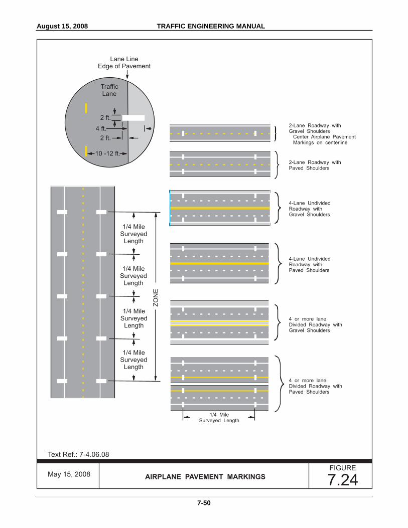
August 15, 2008 TRAFFIC ENGINEERING MANUAL
7-50
Text Ref.: 7-4.06.08
FIGURE
AIRPLANE PAVEMENT MARKINGS 7.24
1/4 MileSurveyed
Length
1/4 MileSurveyed
Length
1/4 MileSurveyed
Length
1/4 MileSurveyed
Length
ZO
NE
2-Lane Roadway withGravel Shoulders
Center Airplane PavementMarkings on centerline
4 or more laneDivided Roadway withGravel Shoulders
2-Lane Roadway withPaved Shoulders
4 or more laneDivided Roadway withPaved Shoulders
4-Lane UndividedRoadway withGravel Shoulders
4-Lane UndividedRoadway withPaved Shoulders
1/4 MileSurveyed Length
TrafficLane
Lane LineEdge of Pavement
2 ft.
2 ft.
4 ft.
10 -12 ft.
May 15, 2008

October 31, 20098 TRAFFIC ENGINEERING MANUAL
7-51
FIGUREHIGH OCCUPANCY VEHICLE (HOV)
PAVEMENT MARKINGS 7.25
Metered Ramp
30 in.
12 ft.
6 in.
White HOVPavement Marker
R3-X3
2 P ERSO N
CAR POO LS
B U S ES &
O N LY
M O TO R CYC L E S
October 31, 2009
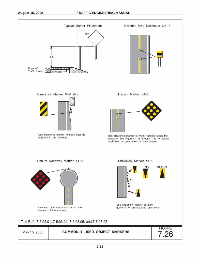
August 15, 2008 TRAFFIC ENGINEERING MANUAL
7-52
���
Text Ref.: 7-5.02.01, 7-5.03.01, 7-5.03.05, and 7-5.03.06
FIGURECOMMONLY USED OBJECT MARKERS
7.26
OR
4 ft.
Edge ofTraffic Lane
Use clearance marker to mark hazardsadjacent to the roadway.
Use end of roadway marker to markthe end of the roadway.
Use snowplow marker to markguardrail for snowplowing operations.
Use clearance marker to mark hazards within theroadway. See Figures 7.33 through 7.35 for typicalapplication in gore areas of interchanges.
Shoulder
Typical Marker Placement
Clearance Marker X4-4 (R)
End of Roadway Marker X4-11
Cylinder Style Delineator X4-13
Hazard Marker X4-2
Snowplow Marker X4-5
END BEGIN
May 15, 2008

August 15, 2008 TRAFFIC ENGINEERING MANUAL
7-53
Text Ref.: 7-4.03.05 and 7-5.03.02
FIGURENARROW BRIDGE SIGNING, MARKING & DELINEATION 7.27
X4-5
X4-4 (L) X4-4 (R)
400 ft.
0
50 ft.
100 ft.
150 ft.
200 ft.
300 ft.
600 ft.
800 ft.
1000 ft.
Greater than 18 feet but less thanthe approach roadway width
(not including shoulders)
GUARDRAIL
Structural plate beam typeguardrail:Where inplace, mount delineatorson steel or plastic post sectionsfastened to wood posts 4 ft. abovethe edge of pavement.
3 cable type guardrail:1. Where inplace on tangent
approaches, mount delineatorssame as above at spacingindicated.
2. Where approach is on a curve,mount same as above but atreduced spacing based onMN MUTCD, Table 3D-1.
W14-3 W5-2
4 in. x 10 in. Yellow Alignment Delineator
4 in. Solid Line Yellow(see Chart 7-4)
4 in. Broken Line Yellow
4 in. Solid Line White
Single White Alignment Delineator
NOTE: Treatment is based on idealconditions with a tangent approach,good sight distance, etc.
B R I D G E
NAR ROW
May 15, 2008

August 15, 2008 TRAFFIC ENGINEERING MANUAL
7-54
Text Ref.: 7-5.03.02
FIGUREONE LANE BRIDGE SIGNING, MARKING & DELINEATION 7.28
R1-2
X4-4 (L) X4-4 (R)
400 ft.
0
50 ft.
100 ft.
150 ft.
200 ft.
300 ft.
600 ft.
800 ft.
1000 ft.
1500 ft.
Less than 18 ft.
GUARDRAIL
Structural plate beam typeguardrail:where in place, mount delineatorson steel or plastic post sectionsfastened to wood posts 4 ft. abovethe edge of pavement.
3 cable type guardrail:1. Where in place on tangent
approaches, mount delineatorssame as above at spacingindicated.
2. Where approach is on a curve,mount same as above but atreduced spacing based onMN MUTCD, Table 3D-1.
W14-3 W3-2a
4 in. x 8 in. Yellow Alignment Delineator
4 in. Solid Line Yellow(see Chart 7-4)
4 in. Broken Line Yellow
4 in. Solid Line White
Single White Alignment Delineator
NOTE: Treatment is based on idealconditions with a tangentapproach, good sightdistance, etc.
Y I E LD
T O
O N CO M I N G
TRAFF I C
OPTIONAL
OPTIONAL
BRIDGE
ONE LANE
W5-3
May 15, 2008

August 15, 2008 TRAFFIC ENGINEERING MANUAL
7-55
������
Text Ref.: 7-5.03.03
FIGUREUNPROTECTED LARGE CULVERT &
CATTLEPASS MARKING 7.29
42 in. - 20 ft.
H
H
4 ft
Shoulder
Shoulder
Shoulder P.I.
0 - 8 ft.
ShoulderRoadway
Back-to-Back Type 2Object Markers
(Yellow)
End of Culvert
Flexible Postor
2 lb./ft. Steel Post
May 15, 2008
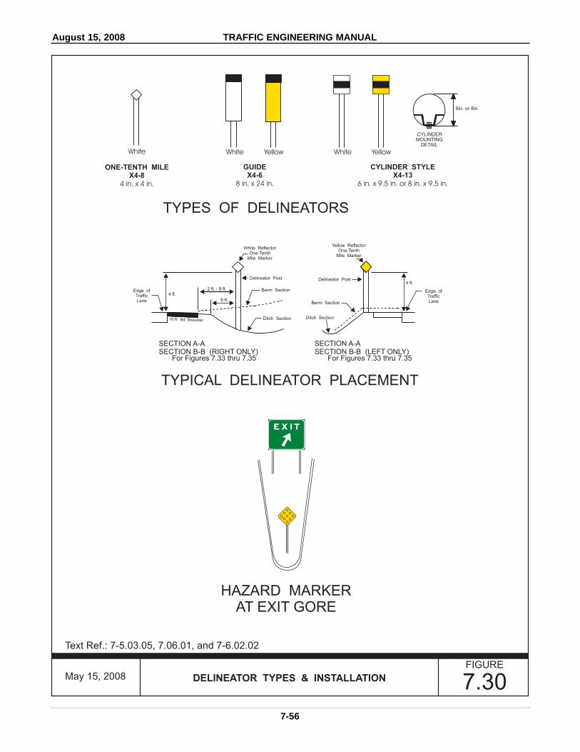
August 15, 2008 TRAFFIC ENGINEERING MANUAL
7-56
Text Ref.: 7-5.03.05, 7.06.01, and 7-6.02.02
FIGURE
DELINEATOR TYPES & INSTALLATION 7.30
TYPES OF DELINEATORS
HAZARD MARKERAT EXIT GORE
TYPICAL DELINEATOR PLACEMENT
4 ft.
10 ft. Bit. Shoulder
2 ft. - 8 ft.
6 ft.
SECTION A-ASECTION B-B (RIGHT ONLY)
SECTION A-ASECTION B-B (LEFT ONLY)
For Figures 7.33 thru 7.35 For Figures 7.33 thru 7.35
Ditch SectionDitch Section
Berm Section
Berm Section
Delineator PostDelineator Post4 ft.
Edge ofTrafficLane
Edge ofTrafficLane
CYLINDER STYLEX4-13
ONE-TENTH MILEX4-8
GUIDEX4-6
8 in. x 24 in. 6 in. x 9.5 in. or 8 in. x 9.5 in.4 in. x 4 in.
White White Yellow
E X I T
White ReflectorOne-Tenth
Mile Marker
Yellow ReflectorOne-Tenth
Mile Marker
6in. or 8in.
CYLINDERMOUNTING
DETAIL
White Yellow
May 15, 2008

August 15, 2008 TRAFFIC ENGINEERING MANUAL
7-57
Text Ref.: 7-5.03.05, 7.06.01, and 7-6.02.02
FIGURE
DELINEATOR TYPES & INSTALLATION 7.31May 15, 2008
Also mountedon sign post
OPTIONAL LAYOUT
CylinderDelineator
Also mountedon STOP sign post
CylinderStyle
Delineator

August 15, 2008 TRAFFIC ENGINEERING MANUAL
7-58
Text Ref.: 7-6.02.03
FIGURE
DIVIDED HIGHWAY INTERSECTION DELINEATION 7.32
Cylinder Style Delineatormounted independentlyor to Yield sign post(if present)
Cylinder Style Delineatormounted on Yield sign post
Cylinder Style Delineator
Delineation of Medianunder 30 ft. width betweenedge of roadway
Delineation of Medianover 30 ft. width betweenedge of roadway
NOTE: Corners to be handledas shown in Figure 7.31.
May 15, 2008
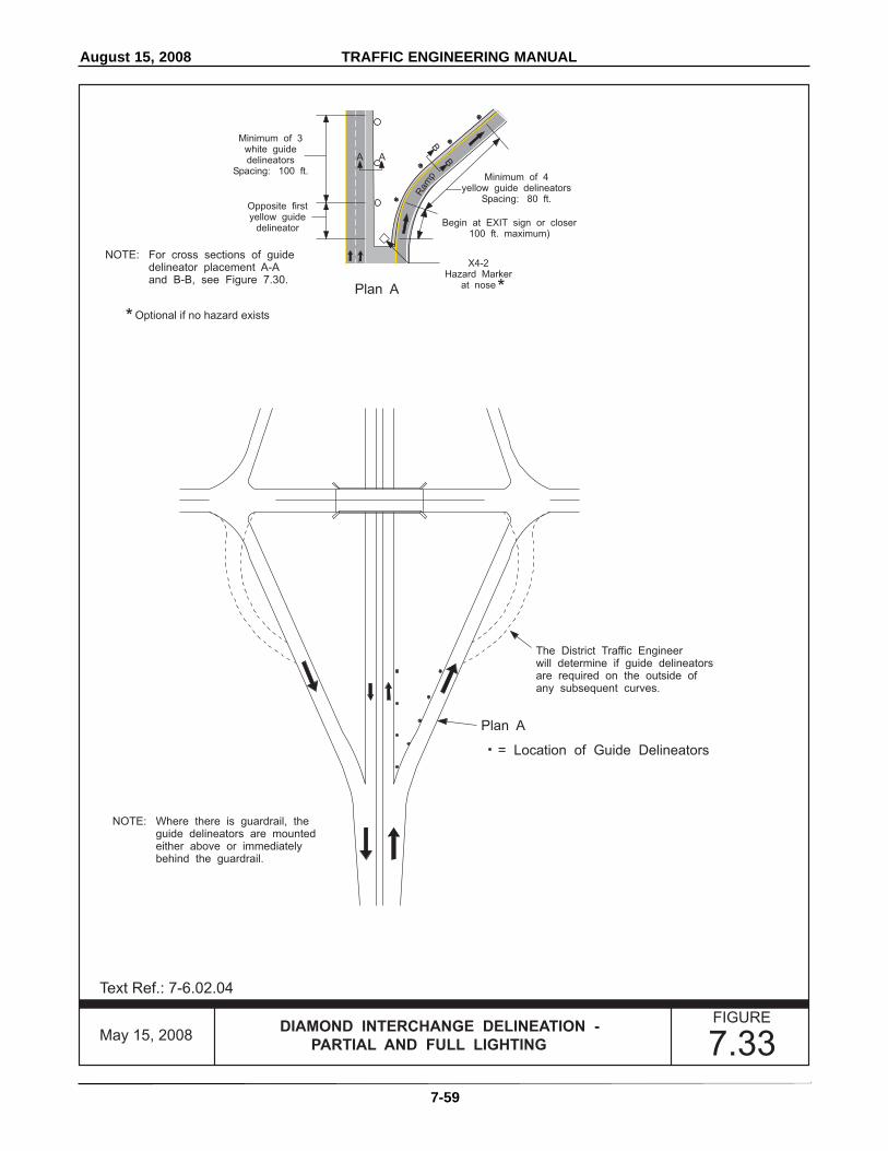
August 15, 2008 TRAFFIC ENGINEERING MANUAL
7-59
Text Ref.: 7-6.02.04
FIGUREDIAMOND INTERCHANGE DELINEATION -
PARTIAL AND FULL LIGHTING 7.33
Plan A
Plan A
= Location of Guide Delineators
The District Traffic Engineerwill determine if guide delineatorsare required on the outside ofany subsequent curves.
NOTE: Where there is guardrail, theguide delineators are mountedeither above or immediatelybehind the guardrail.
NOTE: For cross sections of guidedelineator placement A-Aand B-B, see Figure 7.30.
X4-2Hazard Marker
at nose
Minimum of 4yellow guide delineators
Spacing: 80 ft.
Ram
p
A
B
A B
Minimum of 3white guidedelineators
Spacing: 100 ft.
Opposite firstyellow guide
delineatorBegin at EXIT sign or closer
100 ft. maximum)
*
*Optional if no hazard exists
May 15, 2008

August 15, 2008 TRAFFIC ENGINEERING MANUAL
7-60
Text Ref.: 7-6.02.04
FIGUREDIAMOND INTERCHANGE DELINEATION -
UNLIT 7.34
Plan A
= Location of Delineators
The District Traffic Engineer will determineif guide delineators are required on theoutside of any subsequent curves.
ENTRANCE RAMPMinimum of 5 guide delineatorson the outside of the curve.
Spacing: 80 ft.Lateral placement: see Figure 7.30,
Section B-B
Delineate all of the curve.Terminate at the back of the concretenose or at the Merging Traffic sign(W4-1).
The District Traffic Engineer will determine if guidedelineators are required on a Deceleration Lane orTaper at ramp exits. If installed, use white GuideMarker (X4-5). Begin at the point of taper andcarry past the gore nose.
Spacing: 100 ft. on center.Lateral placement: see Figure 7.30, Section A-A
Plan A
NOTE: Where there is guardrail, theguide delineators are mountedeither above or immediatelybehind the guardrail.
NOTE: For cross sections of guidedelineator placement A-Aand B-B, see Figure 7.30.
X4-2Hazard Marker
at nose
Minimum of 4yellow guide delineators
Spacing: 80 ft.
Ram
p
A
B
A B
Minimum of 3white guidedelineators
Spacing: 100 ft
Opposite firstyellow guide
delineatorBegin at EXIT sign or closer
100 ft. maximum
*
*Optional if no hazard exists
May 15, 2008

August 15, 2008 TRAFFIC ENGINEERING MANUAL
7-61
Text Ref.: 7-6.02.04
FIGURECLOVERLEAF INTERCHANGE DELINEATION -
FULL LIGHTING 7.35
= Location of Guide Delineators
At unlit interchanges, the District Traffic Engineerwill determine if guide delineators are required on aDeceleration Lane or Taper at ramp exits. If installed,use white Guide Delineator (X4-5). Begin at thepoint of taper and carry past the gore nose.
Spacing: 100 ft. on center.Lateral placement: see Figure 7.30, Section A-A
NOTE: Where there is guardrail, the guidedelineators are mounted either aboveor immediately behind the guardrail.
Plan A
Plan A
Plan A
Plan A
Plan A
Plan B
NOTE: For examples of cross sectionsA-A and B-B from Plan A andPlan B, see Figure 7.30.
X4-2Hazard Marker
at nose
X4-2Hazard Marker
at nose
Minimum of 4yellow guide delineators
Spacing: 80 ft.
Minimum of 5yellow guidedelineators
Spacing: 40 ft.
Loop
A
AB
A
B
Minimum of 3white guidedelineators
Spacing: 100 ft.
Minimum of 3white guide delineators
Spacing: 100 ft.Lateral: 7 ft.
Opposite firstyellow guide
delineator
100 ft.maximum
Begin at EXIT sign or closer100 ft. maximum
Begin at EXIT signor closer
50 ft. maximum
**
* Optional if no hazard exists
Ram
p
B
A B
May 15, 2008
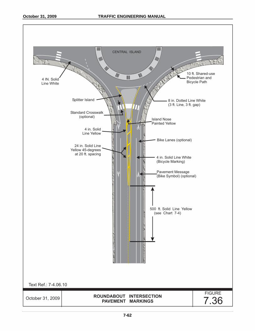
October 31, 2009 TRAFFIC ENGINEERING MANUAL
7-62
Text Ref.: 7-4.06.10
FIGUREROUNDABOUT INTERSECTION
PAVEMENT MARKINGS 7.36
Standard Crosswalk(optional)
Splitter Island 8 in. Dotted Line White(3 ft. Line, 3 ft. gap)
Island NosePainted Yellow
10 ft. Shared-usePedestrian andBicycle Path
Bike Lanes (optional)
4 in. Solid Line White(Bicycle Marking)
4 in. SolidLine Yellow
4 IN. SolidLine White
24 in. Solid LineYellow 45-degrees
at 20 ft. spacing
Pavement Message(Bike Symbol) (optional)
CENTRAL ISLAND
500 ft. Solid Line Yellow(see Chart 7-4)
October 31, 2009

August 15, 2008 TRAFFIC ENGINEERING MANUAL
7-63
Text Ref.: 7-4.04.01
CHARTMINIMUM PASSING SIGHT DISTANCE 7-3
85th Percentile SpeedMPH
30 or less31-4041-5051-6061 or greater
500600800
1,0001,100
167200267333367
Minimum Sight DistanceFeet Yards
May 15, 2008
Text Ref.: 7-4.04.01
CHARTMINIMUM LENGTH OF A NO PASSING ZONE
IN ADVANCE OF A STOP CONDITION 7-2
Speed Limit(or 85th Percentile)
MPH
0 - 3040 - 5055 or greater
300400500
100133167
Minimum Length
Feet Yards
May 15, 2008
Text Ref.: 7-4.04.01
CHARTMINIMUM DISTANCE OR GAPBETWEEN NO PASSING ZONES 7-4
85th Percentile SpeedMPH
20-3940-5455 and above
500650800
167217267
Distance Between ZonesFeet Yards
If the distance between zones is less than specified,the zones should be connected.
May 15, 2008

August 15, 2008 TRAFFIC ENGINEERING MANUAL
7-64
Text Ref.: 7-5.02.01
CHART
OBJECT MARKERS 7-5
12”
x36”
18”
x36”
Wid
eA
ngle
VIP
Retr
ore
flective
Sheeting
(TY
PE
IX)
Encapsula
ted
Retr
ore
flective
Sheeting
-(T
ype
III)
NA
ME
OB
JE
CT
MA
RK
ER
SIZ
EC
OLO
RIN
FO
RM
AT
ION
SE
EM
NM
UT
CD
Hazard
Mark
er
Type
1(X
4-2
)
Culv
ert
Mark
er
Type
2(X
4-3
)
Cle
ara
nce
Mark
er
Type
3(X
4-4
)
End
of
Roadw
ay
Mark
er
(X4-1
1)
18”
x18”
6”
x12”
18”
x18”
All
Yello
wor
Yello
won
Bla
ck
Yello
won
White
or
All
Yello
w
Bla
ck
on
Yello
w
All
Red
or
Red
on
Bla
ck
Section
3C
-3
Section
3C
-3
Section
3C
-3
Section
3C
-4
Snow
plo
wM
ark
er
(X4-5
)6”
x12”
Bla
ck
on
Yello
wN
one
(ve
rt.
or
ho
rz.)
(le
fto
rrig
ht)
May 15, 2008

August 15, 2008 TRAFFIC ENGINEERING MANUAL
7-65
Text Ref.: 7-5.04
CHART
DELINEATOR FABRICATION DETAILS 7-6
Wid
eA
ngle
VIP
Retr
ore
flective
Sheeting
(TY
PE
IX)
Type
VII
MD
Retr
ore
flective
Sheeting
NA
ME
DE
LIN
EA
TO
RS
IZE
CO
LO
RIN
FO
RM
AT
ION
SE
EM
NM
UT
CD
One
Tenth
Mile
Delin
eato
r(X
4-8
)
Guid
eD
elin
eato
r(X
4-6
)
Chevro
nA
lignm
ent
Sig
n(W
1-8
)
Alig
nm
entD
elin
eato
r(X
4-7
)
4”
x4”
8”
x24”
18”
x24”
4”
x8”
White
Bla
ck
top
on
White
or
Yello
w
Bla
ck
on
Yello
w
White
or
Yello
w
Section
2D
-46
Section
2C
-10
None
None
Cylin
der
Sty
leD
elin
eato
r(X
4-1
3)
6”
or
8”
Dia
mete
r9.5
”H
eig
ht
White
or
Yello
wS
ection
3D
-4.5
May 15, 2008

August 15, 2008 TRAFFIC ENGINEERING MANUAL
7-66
Text Ref.: 7-6.02.02
CHARTFINDING THE DEGREE OF CURVE
FOR A HORIZONTAL CURVE 7-7
200 foot Chord
"M" Distance
Take 200 foot tape, chain, or rope and stretch it between two points on acurve. At the center (100 foot mark), measure the distance in feet andinches between the chord and the arc.
DEGREE OF CURVE RELATED TO "M" FOR A 200 FOOT CHORD
Degree ofCurve
Distance "M"feet
Distance "M"inches
Radiusfeet
0 30'
1 00’
1
o
o
o
o
o
o
o
o
o
o
o
o
o
o
o
o
o
o
o
o
30'
2 00’
2 30'
3 00’
3 30'
4 00’
4 30'
5 00’
5 30'
6 00’
6 30'
7 00’
7 30'
8 00’
8 30'
9 00’
9 30'
10 00’
0.44
0.87
1.31
1.75
2.18
2.62
3.06
3.96
3.49
3.93
4.37
4.81
5.25
5.69
6.13
6.57
7.02
7.46
7.90
8.35
8.79
5-1/2
10-1/2
15-3/4
21
26
31-1/2
36-3/4
42
47-1/2
52-1/2
57-3/4
63
68-3/8
73-5/8
78-7/8
84-1/4
89-1/2
94-3/4
100-1/4
105-1/5
5,730
3,820
2,865
2,292
1,910
1,637
1,432
1,273
1,146
1,042
955
881
819
764
716
674
637
603
573
May 15, 2008

August 15, 2008 TRAFFIC ENGINEERING MANUAL
7-67
