table of contents - rydon group
TRANSCRIPT


Table of Contents
Introduction:
Frictional shaft-hub-connections 3
Categories of RYDON shaft-hub-connections 3.1
Ensured Torques with the RYDON Calculation Method 4
A. Shrink Discs:
Design and function of Shrink Discs 5
Shrink Discs RLC 608 6
Shrink Discs RLC 606 9
Shrink Discs RLC 603 11
Technical Points for Shrink Discs 14
B. Cone Clamping Elements:
Design and function of Cone Clamping Elements 15
Hub Width and Hub Outer Diameter 15.1
Cone Clamping Elements RLC 110 16
Cone Clamping Elements RLC 110 K 18
Cone Clamping Elements RLC 130 20
Cone Clamping Elements RLC 131 22
Cone Clamping Elements RLC 132 24
Cone Clamping Elements RLC 133 26
Cone Clamping Elements RLC 200 28
Technical Points for Cone Clamping Elements 30
2
Frictional shaft-hub-connections
Why frictional shaft-hub-connections: Frictional shaft-hub-connections are standard machine elements used to connect shafts and hubs. They are capable of transmitting Torque, axial forces, radial forces and bending moments.
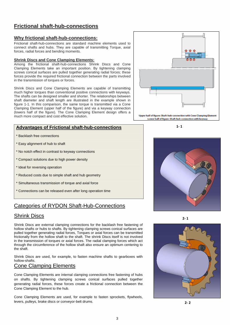
Shrink Discs and Cone Clamping Elements: Among the frictional shaft-hub-connections Shrink Discs and Cone Clamping Elements take an important position. By tightening clamping screws conical surfaces are pulled together generating radial forces; these forces provide the required frictional connection between the parts involved in the transmission of torques or forces. Shrink Discs and Cone Clamping Elements are capable of transmitting much higher torques than conventional positive connections with keyways. The shafts can be designed smaller and shorter. The relationships between shaft diameter and shaft length are illustrated in the example shown in figure 1-1. In this comparison, the same torque is transmitted via a Cone Clamping Element (upper half of the figure) and via a keyway connection (lowers half of the figure). The Cone Clamping Element design offers a much more compact and cost effective solution.
Categories of RYDON Shaft-Hub-Connections
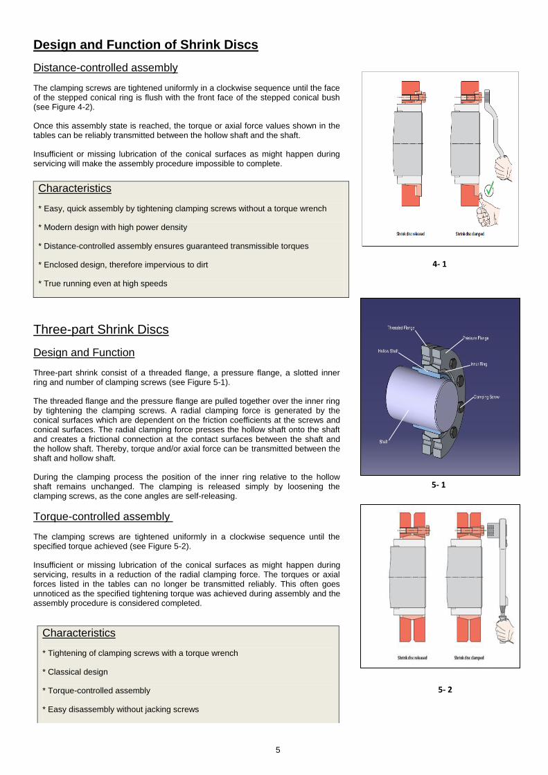
Shrink Discs
Shrink Discs are external clamping connections for the backlash free fastening of hollow shafts or hubs to shafts. By tightening clamping screws conical surfaces are pulled together generating radial forces, Torques or axial forces can be transmitted frictionally from the hollow shaft to the shaft. The shrink Discs itself is not involved in the transmission of torques or axial forces. The radial clamping forces which act through the circumference of the hollow shaft also ensure an optimum centering to the shaft.
Shrink Discs are used, for example, to fasten machine shafts to gearboxes with hollow-shafts.
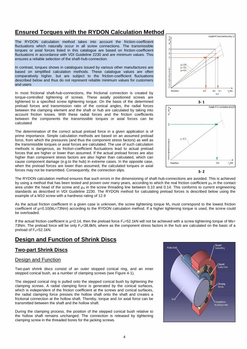
Cone Clamping Elements
Cone Clamping Elements are internal clamping connections free fastening of hubs
on shafts. By tightening clamping screws conical surfaces pulled together
generating radial forces, these forces create a frictional connection between the
Cone Clamping Element to the hub.
Cone Clamping Elements are used, for example to fasten sprockets, flywheels,
levers, pulleys, brake discs or conveyor-belt drums.
3
Advantages of Frictional shaft-hub-connections
* Backlash free connections
* Easy alignment of hub to shaft
* No notch effect in contrast to keyway connections
* Compact solutions due to high power density
* Ideal for reversing operation
* Reduced costs due to simple shaft and hub geometry
* Simultaneous transmission of torque and axial force
* Connections can be released even after long operation time
2- 2
1- 1
2- 1
Ensured Torques with the RYDON Calculation Method
The RYDON calculation method takes into account the friction-coefficient fluctuations which naturally occur in all screw connections. The transmissible torques or axial forces listed in this catalogue are based on friction-coefficient fluctuations in accordance with VDI Guideline 2230 and are minimum values. This ensures a reliable selection of the shaft-hub-connection.
In contrast, torques shows in catalogues issued by various other manufactures are based on simplified calculation methods. These catalogue values are often comparatively higher, but are subject to the friction-coefficient fluctuations described below and thus do not represent reliable minimum values for customers and users
In most frictional shaft-hub-connections, the frictional connection is created by torque-controlled tightening of screws. These axially positioned screws are tightened to a specified screw tightening torque. On the basis of the determined preload forces and transmission ratio of the conical angles, the radial forces between the clamping element and the shaft or hub are calculated by taking into account friction losses. With these radial forces and the friction coefficients between the components the transmissible torques or axial forces can be calculated
The determination of the correct actual preload force in a given application is of prime importance. Simple calculation methods are based on an assumed preload force, from which the pressures (and thus the component stress factors) as well as the transmissible torques or axial forces are calculated. The use of such calculation methods is dangerous, as friction-coefficient fluctuations lead to actual preload forces that are higher or lower than assumed. If the actual preload forces are also higher than component stress factors are also higher than calculated, which can cause component damage (e.g.to the hub) in extreme cases. In the opposite case, when the preload forces are lower than assumed, the calculated torques or axial forces may not be transmitted. Consequently, the connection slips.
The RYDON calculation method ensures that such errors in the dimensioning of shaft-hub-connections are avoided. This is achieved by using a method that has been tested and proven over many years, according to which the real friction coefficient µK in the contact area under the head of the screw and µG in the screw threading line between 0.10 and 0.14. This conforms to current engineering standards as described in VDI Guideline 2230. The RYDON method for calculating preload forces is described below using the example of a M10 screw with a hardness rating of 12.9
As the actual friction coefficient in a given case is unknown, the screw tightening torque Ms must correspond to the lowest friction coefficient of µ=0.10(Ms=73Nm) according to the RYDON calculation method. If a higher tightening torque is used, the screw could be overloaded.
If the actual friction coefficient is µ=0.14, then the preload force Fs=52.1kN will not be achieved with a screw tightening torque of Ms= 73Nm. The preload force will be only Fs=38.8kN, where as the component stress factors in the hub are calculated on the basic of a preload of Fs=52.1kN.
Design and Function of Shrink Discs
Two-part Shrink Discs
Design and Function
Two-part shrink discs consist of an outer stopped conical ring, and an inner stepped conical bush, as a number of clamping screws (see Figure 4-1).
The stepped conical ring is pulled onto the stepped conical bush by tightening the clamping screws. A radial clamping force is generated by the conical surfaces, which is independent of the friction coefficient at the screws and conical surfaces, the radial clamping force presses the hollow shaft onto the shaft and creates a frictional connection at the hollow shaft. Thereby, torque and /or axial force can be transmitted between the shaft and the hollow shaft.
During the clamping process, the position of the stepped conical bush relative to the hollow shaft remains unchanged. The connection is released by tightening clamping screw in the threaded bores for the jacking screws.
4
3- 1
3- 2
4- 1
Design and Function of Shrink Discs
Distance-controlled assembly
The clamping screws are tightened uniformly in a clockwise sequence until the face of the stepped conical ring is flush with the front face of the stepped conical bush (see Figure 4-2).
Once this assembly state is reached, the torque or axial force values shown in the tables can be reliably transmitted between the hollow shaft and the shaft.
Insufficient or missing lubrication of the conical surfaces as might happen during servicing will make the assembly procedure impossible to complete.
Three-part Shrink Discs
Design and Function
Three-part shrink consist of a threaded flange, a pressure flange, a slotted inner ring and number of clamping screws (see Figure 5-1).
The threaded flange and the pressure flange are pulled together over the inner ring by tightening the clamping screws. A radial clamping force is generated by the conical surfaces which are dependent on the friction coefficients at the screws and conical surfaces. The radial clamping force presses the hollow shaft onto the shaft and creates a frictional connection at the contact surfaces between the shaft and the hollow shaft. Thereby, torque and/or axial force can be transmitted between the shaft and hollow shaft.
During the clamping process the position of the inner ring relative to the hollow shaft remains unchanged. The clamping is released simply by loosening the clamping screws, as the cone angles are self-releasing.
Torque-controlled assembly
The clamping screws are tightened uniformly in a clockwise sequence until the specified torque achieved (see Figure 5-2).
Insufficient or missing lubrication of the conical surfaces as might happen during servicing, results in a reduction of the radial clamping force. The torques or axial forces listed in the tables can no longer be transmitted reliably. This often goes unnoticed as the specified tightening torque was achieved during assembly and the assembly procedure is considered completed.
5
Characteristics
* Easy, quick assembly by tightening clamping screws without a torque wrench
* Modern design with high power density
* Distance-controlled assembly ensures guaranteed transmissible torques
* Enclosed design, therefore impervious to dirt
* True running even at high speeds
Characteristics
* Tightening of clamping screws with a torque wrench
* Classical design
* Torque-controlled assembly
* Easy disassembly without jacking screws
4- 1
5- 1
5- 2

Shrink Discs RLC 608
Two-part design, highest transmissible torques
Features
Highest transmissible torques
Easy, quick assembly by tightening clamping screws without a torque wrench
Distance-controlled assembly ensures guaranteed transmissible torques
Enclosed design, therefore impervious to dirt
True running even at high speeds
Centre’s the hollow shaft or hub to the shaft
For hollow shafts or hubs with outer diameters of 30 mm up to 390 mm
Application Example
Backlash free connection of a hollow-shaft gearbox to a machine shaft with a Shrink Disc RLC 608. The backlash free connection reduces the risk of fretting corrosion. As a result, the connection can be easily disassembled even after long periods of operation.
Transmissible torques and axial forces
The transmissible torques or axial forces listed on page 7 through 8 are subject to the following tolerances, surface characteristics and material requirements. Please
contact us in the case of deviations.
Tolerances
Other fits may be selected, provided the joint clearance between the shaft and the hollow shaft remains within the indicated ranges.
Surfaces
Average surface roughness at the contact surfaces between the shaft and the hollow shaft Ra ≤ 1.6µm.
Materials
The following apply to the shaft and the hollow shaft:
Yield strength Re ≥ 360N/mm2
E-module ca.206kN/mm2
Shrink discs inner ring are manufactured from high-carbon steel. Outer ring are made from forged and heat treated alloy steel.
Installation
Please request our installation and operating instructions for Shrink Discs RLC 608.
Simultaneous Transmission of torque and axial force
The transmissible torques M which are shown in the tables apply for forces F= 0kN and conversely, the indicated axial forces F apply to torques M= 0 Nm. If torque and axial force are to be transmitted simultaneously, the transmissible torque and the transmissible axial forces are reduced. Please refer to the technical points on pages 14 and 15.
Example for ordering
Shrink Discs RLC 608 for hollow shaft with an outer diameter d = 80 mm:
RLC 608 44X80
6
dw Hollow shaft bore ISO
Shaft ISO
Joint Clearance
> mm
≤ mm
min. mm
max. mm
24 30
H7 h6
0 0.034
30 50 0 0.041
50 80 0 0.049
80 120 0 0.057
120 160 0 0.065
160 180
H7 g6
0.014 0.079
180 250 0.015 0.09
250 315 0.017 0.101
315 390 0.018 0.111
6- 1
6- 2

Ød ØD Ød1 L1 L2 C B H dw* MtF
kNNumber Size
24 330 27
25 370 29
26 415 31
27 660 48
30 850 56
33 1070 64
34 950 55
35 1030 58
37 1200 64
38 1750 92
40 2000 100
42 2250 105
42 2050 97
45 2400 100
48 2800 110
48 2900 120
50 3200 120
52 3550 130
50 3000 120
55 3800 130
60 4650 150
55 4900 170
60 6100 200
65 7400 220
60 5200 170
65 6400 190
70 7700 220
65 6900 210
70 8200 230
75 9700 250
70 8800 250
75 10350 270
80 12000 300
80 15500 380
85 17800 410
90 20000 440
80 15500 380
85 17800 410
90 20000 440
85 17200 400
90 19700 430
95 22300 460
90 19150 420
95 21700 450
100 24400 480
95 25900 540
100 29000 580
110 36000 650
100 27000 540
105 30200 570
115 37000 640
110 35700 640
115 39500 680
125 47500 760
110 36200 650
115 40000 690
125 48000 760
120 56000 930
125 61000 970
135 72500 1000
12 M16x50 22.656 63 6 82 7320 RLC 608 160X290 160 290 169
12 M14x40 16.3
19 RLC 608 155X263 155 263 159 50 57 6 75 65.8 12 M14x40 15.8
50 57 6 75 65.818 RLC 608 150X263 150 263 159
14 M12x35 11.7
17 RLC 608 140X230 140 230 144 46 53 6 71 61.8 12 M14x40 10.8
46 53 6 68 60.516 RLC 608 130X230 130 230 139
12 M12x35 7.2
15 RLC 608 125X215 125 215 132 42 49 6 63 56.5 12 M12x35 9.2
42 49 6 63 56.514 RLC 608 120X200 120 200 124
12 M12x35 6.6
13 RLC 608 110X185 110 185 114 39 46 6 59 53.5 12 M12x35 6.2
39 46 6 59 53.512 RLC 608 105X185 105 185 114
1094 M10x30 3.4
11 RLC 608 100X170 100 170 104 34 40 5 51 46.4 12 M10x30 4.6
30 35 4 46 41.410 RLC 608 90X155 90 155
2.4
9 RLC 608 80X141 80 141 84 25 29 3 40 35.4 10 M10x25 2.4
9 M8x20 1.4
8 RLC 608 75X138 75 138 79 25 29 3 40 35.4 10 M10x25
23 26.5 3 35 31.87 RLC 608 68X115 68 115 72
8 M8x20 1.1
6 RLC 608 62X110 62 110 66 23 26.5 3 35 31.8 9 M8x20 1.3
23 26.5 3 35 31.85 RLC 608 55X100 55 100 58
6 M8x20 0.6
4 RLC 608 50X90 50 90 53 22 24.5 2 33 29.8 8 M8x20 0.8
20 22.5 2 30 27.8
5 M8x20 0.5
6030RLC 608 30X60
3 RLC 608 44X80 44 80 47
2 72 38 18
1 23
Shrink Discs RLC 608
Shrink Discs released Shrink Discs Clamped
* The shaft diameters dw listed in the table are selected example. For other shaft diameters dw see the technical specification on Page 14.
S.No Modal Nos.
Torque or Axial Force Tightening ScrewsWeight
Kg
Dimensions (mm)
2521916.532
20.5
6 M6x16 0.3
RLC 608 36X72 36 2 28 25.8
7

Ød ØD Ød1 L1 L2 C B H dw* MtF
kNNumber Size
120 56500 940
125 61500 980
135 72500 1000
130 61000 930
135 66500 980
145 78000 1000
130 61500 940
135 67000 990
140 72500 1000
140 97500 1300
145 105000 1400
155 122000 1500
140 96000 1300
145 104000 1400
155 120000 1500
150 92000 1200
155 99000 1200
165 113500 1300
150 107000 1400
155 115000 1400
165 129000 1500
150 108000 1400
155 116000 1400
165 130000 1500
160 160000 2000
170 182000 2100
180 206000 2200
170 190000 2200
180 215000 2300
200 269000 2600
190 247000 2600
200 277000 2700
220 340000 3000
210 335000 3100
220 370000 3300
240 449000 3700
220 386000 3500
230 425000 3600
250 508000 4000
240 465000 3800
250 509000 4000
270 600000 4000
250 564000 4500
260 612000 4700
280 719000 5100
270 658000 4800
280 712000 5000
300 825000 5500
290 903000 6200
300 970000 6400
320 1110000 6900
20 M24x80 197.0
18 M30x100 254.0
18 M24x80 129.0
175.0M24x8020
122.5
135.5
16 M16x50
18 M20x60
20
M20x60 100.0
116.3M24x80
65.3
21 M20x60 79.1
22
112.5
79 7
7
7
7
37.6
16 M16x50 36.6
16 M20x60 51.6
150
430
405
370
340
268 110
100
95
79
7 137
127
121
100
460 288 115 123 7
71
87
92
102
1778142133
158 140
485 308 122 131 8 162 146
520 328 116 125 8
260
280
300
320
144 153 8 195 172
340
360
390 650 399
369590
570 348 127 136 8 170 151
15736
37 RLC 608 390X650
RLC 608 360X590
RLC 608 340X570
31
32
33
34
35
RLC 608 320X520
RLC 608 300X485
RLC 608 280X460
RLC 608 260X430
27
28
29
30 RLC 608 240X405
RLC 608 220X370
RLC 608 200X340
RLC 608 195X340
1689
195
200
220
240
71340 206
206
228
248
100 89
89
107.5
M16x50 33.0
26 RLC 608 190X320 190 320 195 71 79 7 100 89 16 M16x50 33.0
25 RLC 608 185X320 185 320 191 72 79 6 99
12 M16x50
33.9
12 M16x50 22.9
24 RLC 608 180X320 180 320 191 72 79 6 99 89 16 M16x50
56 63 6 82
12 M16x50 23.673
7323 RLC 608 175X300 175 300 179
22 RLC 608 170X300 170 300 179 56 63 6 82
21 RLC 608 165X290 165 290 169 56 63 6 82 73 22.0
Shrink Discs RLC 608
Shrink Discs released Shrink Discs Clamped
* The shaft diameters dw listed in the table are selected example. For other shaft diameters dw see the technical specification on Page 14.
S.No Modal Nos.
Torque or Axial Force Tightening ScrewsWeight
Kg
Dimensions (mm)
8
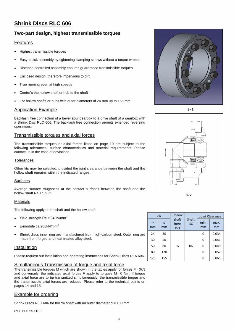
Shrink Discs RLC 606
Two-part design, highest transmissible torques
Features
Highest transmissible torques
Easy, quick assembly by tightening clamping screws without a torque wrench
Distance-controlled assembly ensures guaranteed transmissible torques
Enclosed design, therefore impervious to dirt
True running even at high speeds
Centre’s the hollow shaft or hub to the shaft
For hollow shafts or hubs with outer diameters of 24 mm up to 155 mm
Application Example
Backlash free connection of a bevel spur gearbox to a drive shaft of a gearbox with a Shrink Disc RLC 606. The backlash free connection permits extended reversing operations.
Transmissible torques and axial forces
The transmissible torques or axial forces listed on page 10 are subject to the following tolerances, surface characteristics and material requirements. Please contact us in the case of deviations.
Tolerances
Other fits may be selected, provided the joint clearance between the shaft and the hollow shaft remains within the indicated ranges.
Surfaces
Average surface roughness at the contact surfaces between the shaft and the hollow shaft Ra ≤ 1.6µm.
Materials
The following apply to the shaft and the hollow shaft:
Yield strength Re ≥ 340N/mm2
E-module ca.206kN/mm2
Shrink discs inner ring are manufactured from high-carbon steel. Outer ring are made from forged and heat treated alloy steel.
Installation
Please request our installation and operating instructions for Shrink Discs RLA 606.
Simultaneous Transmission of torque and axial force
The transmissible torques M which are shown in the tables apply for forces F= 0kN and conversely, the indicated axial forces F apply to torques M= 0 Nm. If torque and axial force are to be transmitted simultaneously, the transmissible torque and the transmissible axial forces are reduced. Please refer to the technical points on pages 14 and 15.
Example for ordering
Shrink Discs RLC 606 for hollow shaft with an outer diameter d = 100 mm.
RLC 606 55X100
9
dw Hollow shaft bore ISO
Shaft ISO
Joint Clearance
> mm
≤ mm
min. mm
max. mm
24 30
H7 h6
0 0.034
30 50 0 0.041
50 80 0 0.049
80 120 0 0.057
120 155 0 0.065
8- 1
8- 2

Ød ØD Ød1 L1 L2 C B H dw* MtF
kNNumber Size
19 165 17
20 210 21
21 240 22
24 280 23
25 330 26
26 370 28
27 480 35
30 630 42
33 820 49
30 480 32
32 580 36
34 700 41
34 720 42
35 780 44
37 920 49
38 1150 60
40 1300 65
42 1520 72
42 1300 61
45 1600 71
48 1900 79
48 1700 70
50 1950 78
52 2160 83
50 1900 76
55 2500 90
60 3150 105
55 2700 98
60 3400 113
65 4100 126
60 3300 110
65 4100 126
70 4950 141
65 5500 169
70 6600 188
75 7900 210
70 6200 177
75 7400 197
80 8600 215
80 10500 262
85 11800 277
90 13700 304
85 12500 294
90 14100 313
95 16000 336
90 14500 322
95 16600 349
100 18800 376
95 17000 357
100 18400 368
110 22000 400
95 18400 387
100 20800 416
110 26200 476
100 19900 398
105 22200 422
115 27800 483
110 27000 490
120 32000 533
125 36200 579
110 27000 490
120 32000 533
125 36200 579
Shrink Discs released Shrink Discs released
RLC 606 40X80 40 80 47
RLC 606 36X72 36 72 39
34.4
32.3
29.3
40 2.5 50.5RLC 606 100X170 100 170 104 36.5
41.4
M10x25
46.4
2.8
RLC 606 90X155 90 155 94 31.5 35 2.5 45 11 M10x25 3.4
28 2 38 10RLC 606 80X141 80 141 84 25 34.4
M8x20 1.6
RLC 606 75X138 75 138 79 25 28 2 38 10 M10x25 2.6
27 1.5 35 9RLC 606 68X115 68 115 72 24.5 32.3
M8x20 1.2
RLC 606 62X110 62 110 66 24.5 27 1.5 34.5 9 M8x20 1.5
27 1.5 34.5 8RLC 606 55X100 55 100 58 24.5
32.3
0.5
M8x20 0.6
RLC 606 50X90 50 90 53 22 24 1.5 31 8 M8x20 0.8
22.5 1.5 29.5 6RLC 606 44X80 44 80 47 20.5 27.8
0.6
21
23
25.8
27.8 6 M8x20
15
20.5 1 27.5
20.5 22.5 1.5 29.5
19
5 M6x16 0.3
6 M6x16 0.3
5 M8x20
17
18
19
45.5 3 57 53
RLC 606 125X215 125 215 134 45 49 3 61.5 56.5
3 61 56.5120 197 124 45
RLC 606 130X215
12
13
14
15
16
7
8
9
10
11
* The shaft diameters dw listed in the table are selected example. For other shaft diameters dw see the technical specification on Page 14.
S.No Modal Nos.
Tightening ScrewsTorque (Nm)
1
2
3
4
5
6
14 M10x30 4.6
RLC 606 110X185 110 185 114 40.5
49
20
21
RLC 606 120X197
Weight Kg
RLC 606 30X60 30 60 32 17 19 1 24
17 1 22RLC 606 24X50 24 50 26
Dimensions(mm)
RLC 606 135X230 135
12 M14x40
134 45 49 3 61.5 56.5
144 47 53 4 67 61.8
230 139 47
130 215
14 M14x40 16.0
65.8RLC 606 150X263 150 263 159 51 57 4 72
RLC 606 155X263 155 263 159 51 57 4 72 65.8
14 M14x40 16.0
Shrink Discs RLC 606
11.0
14 M12x35 9.3
14 M12x35 8.7
12 M12x35 6.2
14 M12x35 7.4
11.953 4 66.5 61.8 12 M14x40
RLC 606 140X230 140 230
10

Shrink Discs RLC 603
Three-part design
Highest transmissible torques
Features
Highest transmissible torques
Tightening of clamping screws with a torque wrench
Easy disassembly without jacking screws
Centre’s the hollow shaft or hub to the shaft
For hollow shafts or hubs with outer diameters of 14 mm up to 360 mm
Application Example
Backlash free connection of a cordon shaft flange to a machine shaft with a Shrink Disc RLC 603.The backlash free connection reduces the risk of fretting corrosion. As a result, the connection can be easily disassembled even after long period’s operations.
Transmissible torques and axial forces
The transmissible torques or axial forces listed on page 12 through 13 are subject to the following tolerances, surface characteristics and material requirements. Please contact us in the case of deviations.
Tolerances
Other fits may be selected, provided the joint clearance between the shaft and the hollow shaft remains within the indicated ranges.
Surfaces
Average surface roughness at the contact surfaces between the shaft and the
hollow shaft Ra ≤ 1.6µm.
Materials
The following apply to the shaft and the hollow shaft:
Yield strength Re ≥ 340N/mm2
E-module ca.206kN/mm2
Installation
Please request our installation and operating instructions for Shrink Discs RLC 603
Simultaneous Transmission of torque and axial force
The transmissible torques M which are shown in the tables apply for forces F= 0kN and conversely, the indicated axial forces F apply to torques M= 0 Nm. If torque and axial force are to be transmitted simultaneously, the transmissible torque and the transmissible axial forces are reduced. Please refer to the technical points on pages 14 and 15.
Example for ordering
Shrink Discs RLC 603 for hollow shaft with an outer diameter d = 90 mm:
RLC 603 50X90
11
dw Hollow shaft bore ISO
Shaft ISO
Joint Clearance
> mm
≤ mm
min. mm
max. mm
10 18 H6 j6
0 0.014
18 30 0 0.017
30 50 H6 h6 0 0.032
50 80 H6 g6 0.029 0.048
80 120
H7 g6
0.012 0.069
120 180 0.014 0.079
180 250 0.015 0.090
250 315 0.017 0.101
315 260 0.018 0.111
10- 1
10- 1

Shrink Discs released
Ød ØD L1 L2 B dw* MtF
kNSize
Torque
(Nm)Number
10 25 5
11 35 6
12 50 8
12 50 8
13 70 10
14 90 12
15 130 17
16 150 18
18 200 22
19 180 18
20 210 21
21 250 23
24 310 25
25 340 27
26 380 29
28 460 32
30 590 39
31 630 40
32 630 39
35 780 44
36 860 47
38 940 49
40 1100 55
42 1300 61
42 1200 57
45 1500 66
48 1900 79
48 1800 75
50 2200 88
52 2400 92
50 2000 80
55 2500 90
60 3100 100
55 2500 90
60 3200 100
65 3900 120
60 3200 100
65 3900 120
70 4600 130
65 4700 140
70 6000 170
75 7200 190
70 6300 180
75 7500 200
80 9000 220
75 7200 190
80 9000 220
85 10400 240
80 8500 210
85 9300 210
90 11300 250
80 10500 260
85 12100 280
90 14400 320
Shrink Discs Clamped
Shrink Discs RLC 603
59 9 6.0
RLC 603 120X215 120 215 42 52 58 M10x40 59 12 9.0
56 M10x40RLC 603 115X185 115 185 39 50
12 4.4
RLC 603 110X185 110 185 39 50 56 M10x40 59 9 6.0
49 M8x35RLC 603 100X170 100 170 34 44 30
1.3
7 2.5
RLC 603 90X155 90 155 30 39 44 M8x25 30 10 3.3
37 M8x30RLC 603 80X145 80 145 25 32
8 1.1
25
10
12 10 1.4
RLC 603 75X138 75 138 25 32 37 M8x30 30 7 2.3
34 M6x25RLC 603 68X115 68 115 23 30
7 0.6
RLC 603 50X90 50 90 22 27 31 M6x22 12 8 0.8
29 M6x22RLC 603 44X80 44 2080 12
6 0.3
RLC 603 36X72 36 72 18 23 27 12 5 0.5
25 M5x18RLC 603 30X60 30 60 16 21 6
M6x20
6 0.2
RLC 603 24X50 24 50 14 19 23 M5x18 4 6 0.2
23 M5x18RLC 603 20X50 20 50 14 19 4
4 0.1
RLC 603 16X41 16 41 11 15 19 M5x14 4 5 0.1
15 M5x10RLC 603 14X38 14 38 9 11 4
5
6
7
8
9
* The shaft diameters dw listed in the table are selected example. For other shaft diameters dw see the technical specification on Page 14.
S.No Modal Nos.
Torque or Axial ForceWight
Kg
Tightening ScrewsDimensions (mm)
1
2
3
4
15
16
17
18
34RLC 603 55X100 55 100
14
3013
12
11
12M6x2534302311062RLC 603 62X11010
23 30 M6x25 12
12

Shrink Discs released
Ød ØD L1 L2 B dw* MtF
kNSize
Torque
(Nm)Number
85 11000 250
90 13000 280
95 15000 310
90 12000 260
95 14400 300
100 17000 340
95 14900 310
100 17000 340
105 20000 380
105 2000 380
110 23000 410
115 26000 450
110 21900 390
115 25200 430
120 28600 470
115 31500 540
120 35600 590
125 39000 620
120 31700 520
125 35800 570
130 40000 610
125 34500 550
130 38900 590
135 43400 640
130 36700 560
135 41100 600
140 45700 650
135 49200 720
140 54600 780
145 60400 830
140 51900 740
145 57400 790
150 63200 840
140 61600 880
150 74500 990
155 81300 1040
150 71200 940
155 77900 1000
160 84700 1050
160 90700 1130
165 98600 1190
170 106000 1240
170 119000 1400
180 138000 1530
190 156000 1640
190 161000 1690
200 184000 1840
210 204000 1940
210 213000 2020
220 240000 2180
230 269000 2330
230 274000 2380
240 296000 2460
245 316000 2570
240 310000 2580
250 340000 2720
260 373000 2860
250 381000 3040
260 412000 3160
270 453000 3350
280 453000 3230
290 495000 3410
295 517000 3500
Shrink Discs Clamped
186.024490M20x110175162140590
183.024490M20x110169156134570
133.020490M20x100
Shrink Discs RLC 603
122RLC 603 320X520
RLC 603 340X570
RLC 603 360X590 360
340
320
490 16
155142520
97.0
RLC 603 300X485 300 485 122 142 155 M20x100 490 18 116.0
147 M20x100RLC 603 280X460 280 460 114 134
490 12 62.0
RLC 603 260X430 260 430 103 120 133 M20x90 490 14 77.0
121 M20x80RLC 603 240X405 240 405 92 108
250 12 38.7
RLC 603 220X370 220 370 88 104 114 M16x80 250 15 50.0
96 M16x65RLC 603 200X350 200 350 71 86
250 10 34.1
RLC 603 195X350 195 350 71 86 96 M16x65 250 12 39.6
96 M16x65RLC 603 190X330 190 330 71 86
250 8 22.0
RLC 603 185X330 185 330 71 86 96 M16x65 250 10 35.0
81 M16x60RLC 603 180X300 180 300 56 71
250 8 21.1
RLC 603 175X300 175 300 56 71 81 M16x60 250 8 22.7
81 M16x60RLC 603 170X290 170 290 56 71
100 12 15.4
RLC 603 165X290 165 290 56 71 81 M16x60 250 8 21.7
72 M12x50RLC 603 160X265 160 265 50 64
100 10 10.7
RLC 603 155X265 155 265 50 64 72 M12x50 100 12 16.0
68 M12x45RLC 603 140X230 140 230 46 60
59 12 8.7
RLC 603 130X215 130 215 42 52 58 M10x40 59 12 8.3
58 M10x40RLC 603 125X215 125 215 42 52
35
36
37
38
39
30
31
32
33
34
25
26
27
28
29
20
21
22
23
24
* The shaft diameters dw listed in the table are selected example. For other shaft diameters dw see the technical specification on Page 14.
S.No Modal Nos.
Torque or Axial ForceWight
Kg
Tightening ScrewsDimensions (mm)
19
13

Technical Points for Shrink Discs
Shaft diameter dw
The values for the transmissible torques M or axial forces F given in the tables are calculated for exemplary shaft diameters sw. Values for shaft diameter dw that fall between the shaft diameters dw stated in the table can be determined with sufficient accuracy by interpolation. Please contact us for shaft diameters dw which are smaller than those given in the tables we will gladly calculate the transmissible torques M or forces F for you.
Axial width of contact surface LF
The transmissible of torque or axial force is achieved through the contact surface between shaft and hollow shaft. The pressure created by the Shrink Disc decreases strongly in areas that go beyond the bearing axial width L1 of the Shrink Disc. In such areas with low pressure, there may be micro movements that allow the formation of harmful fretting corrosion.
The axial width of contact surface LF should therefore be limited to:
LF ≤ 1.1*L1
For contact surfaces with a witch that is smaller than L1, there is an increased pressure generated which may damage the shaft and/or hollow shaft or the hub. Please contact us.
Joint clearance between shaft and hollow shaft
When the joint clearance the value given in the tables, the transmissible torque or the transmissible axial force decrease. Additionally, the equivalent stress in the hollow shaft increases in this case. Please contact us. If the joint clearance is lower than indicated the Shrink Disc, shaft or hollow shaft may be damaged during assembly or the torque listed in the tables can no longer be transmitted. Please contact us.
Friction Value
The values listed in the tables for transmissible torques M or axial forces F assume a function value of µ=0.15 in the contact surface between shaft and hollow shaft. The value is safely achieved in a dry and degreased steel/steel paring. For different friction values, the transmissible torque or axial force will change proportionally.
Simultaneous transmission of torque and axial force
The transmissible torque M which are shown in the tables apply for axial forces F = 0kN and conversely, the indicated axial forces F apply to torques M = 0 Nm. If torque and axial force are to be transmitted simultaneously, the transmissible torque and the transmissible axial force are reduced compared to the values listed in the tables for M and F.
For a given axial force FA, the reduced torque Mred is calculated as:
Mred=√M2-(FA*dw/2)
2
For a given torque MA, the reduced axial force Fred is calculated as:
Fred=2/dw√M2
- MA2
Bending moments
Where there is bending moments in addition to the torque MA or the axial force FA, the transmissible torque or transmissible axial force deceases compared to the values for M or F as listed in the tables. Please contact us.
Formula Symbols
dw = shaft diameter/ inner diameter of hollow shaft according to table [mm]
F = Transmissible axial force according to table [kN]
FA = Maximum actual application axial force [kN]
Fred = Reduced axial force [kN]
L1 = Load-bearing axial width of Shrink Disc according to table [mm]
LF = Axial width of contact surface [mm]
M = Transmissible torque according to table [mm]
MA = Maximum actual application torque [mm]
Mred = Reduced torque [Nm]
µ = Friction value
14
12- 1

Design and Function Cone Clamping Elements
Cone Clamping Elements as shown in figure 13-1 consist of an outer ring with
inside cone and inner ring with outside cone as well as a number of clamping
screws.
The outer ring is pulled onto the inner ring by tightening the clamping screws.
Radial clamping forces are generated by the conical surfaces which are dependent
on the torques of the clamping screws, the cone angle and the friction coefficient at
the screws and conical surfaces.
The radial clamping forces press the outer ring into the hub bore and the inner ring
onto the shaft and create a frictional connection at the respective contact surfaces.
In this way, torque and/or axial force can be transmitted between the shaft and the
hub.
In the configuration shown in the illustration, the connection is released by turning
some of the clamping screws into the threaded bores for the jacking screws. This
presses off the outer ring.
Centering the hub to the shaft
As a rule, a true running accuracy of the hub to the shaft of 0.02 to 0.04 mm can be
achieved with Cone Clamping elements of the series RLC 200. With these series
the hub must be centered to the shaft in accordance with the specific requirements
of the application.
No axial displacement of the hub relative to the
shaft during clamping
The series for which no axial displacement of the hub relative to the shaft is created
during the clamping procedure. This is ensured, for example, by a fixed hub
backstop point on the collar of the inner ring. For all other series, the clamping
procedure (tightening the clamping screws and pulling the outer ring onto the inner
ring) involves an axial hub displacement.
Hub Width and Hub Outer Diameter
Frictional shaft-hub-connections with Cone Clamping Elements create very high
radial clamping forces. This requires a hardness analysis of shaft and hub. For this,
the Cone Clamping Element tables list the maximum pressures pw in the contact
surface at the shaft and the maximum pressures PN in the contact surface at the
hub.
The contact pressure PW leads to radial stress in the shaft that is usually not critical
for steel shafts. There is always a tangential stress δt in the hub, and for thin-walled
hubs it may be a multiple of the initiated pressure PN. The amount of the actual
tangential stress depends on the load-bearing hub width N, the hub outer diameter
K and the pressure PN. Calculation of load-bearing hub width N takes into account
the fact that hub pressure PN is transmitted by load-bearing width L1 and taken up
beyond it in an angle of approximately 26.5°
For the different Cone Clamping Element series, the tables list the required hub
width Nmin and the required hub outer diameter Kmin for three exemplary yield
strengths Re of the hub. Thereby, the hub is to be arranged as seen in figure 15-1
for Cone Clamping Elements with a fixed backstop point.
For any deviating hub arrangement and/or lower yield strengths Re of the hub
material, the shaft-hub-connection must be verified according to the technical
points on pages 30 and 31.
Hub Arrangement for Cone Clamping Elements with a fixed backstop point
15
13- 1
13- 1
14- 1
13- 2

Cone Clamping Elements RLC 110
Centre the hub to the shaft
Radial flat height
Features
Centre the shaft to the hub.
Highest transmissible torques.
Radial flat height is particularly suitable for small hub outer diameters.
No axial displacement between hub and shaft during clamping procedure due to
fixed backstop point.
For shafts diameters between 6 mm up to 120 mm.
Application example
Backlash free connection of a screw gear and simultaneous coupling of the divided
drive shaft of a continuous heating furnace with two Cone Clamping Elements RLC
110. A simple and cost-effective solution, because clamping the screw gear and
coupling the shaft ends is achieved simultaneously by the Cone Clamping
Elements.
Transmissible torques and axial forces
The transmissible torques or axial forces listed on page 17 are subject to the
following tolerances, surface characteristics and material requirements. Please
contact us in the case of deviations.
Tolerances
h8 for shaft diameter d
H8 for hub bore D
Surfaces
Average surface roughness at the contact surfaces between the shaft and the hub bore: Ra ≤ 1.6µm
Materials
The following apply to the shaft and the hub:
E-module ≥ 170kN/mm2
Installation
Please request our installation and operating instructions for Cone Clamping Elements RLC 110.
Simultaneous Transmission of torque and axial force
The transmissible torques M which are shown in the tables apply for forces F= 0kN and conversely, the indicated axial forces
F apply to torques M= 0 Nm. If torque and axial force are to be transmitted simultaneously, the transmissible torque and the
transmissible axial forces are reduced. Please refer to the technical points on pages 30 and 31.
Example for ordering
Cone Clamping Element RLC 110 for shaft diameter d = 50 mm:
RLC 110 50X65
16
15- 1
15- 2

Torque
(Nm)
Ød ØD ØD1 L1 L2 L3 B MtShaft
pw
Hub
pnSize
Torque
(Nm)Qty.
1 RLC 110 6X14 6 14 25 10 19 21 24 14 228 98 M3x10 1.8 4 0.1
2 RLC 110 8X15 8 15 27 12 22 25 29 27 223 119 M4x10 4.5 3 0.1
3 RLC 110 9X16 9 16 28 14 23 26 30 41 218 122 M4x10 4.5 4 0.1
4 RLC 110 10X16 10 16 29 14 23 26 30 46 196 122 M4x10 4.5 4 0.2
5 RLC 110 11X18 11 18 32 14 23 26 30 50 185 113 M4x10 4.5 4 0.2
6 RLC 110 12X18 12 18 32 14 23 26 30 55 169 113 M4x10 4.5 4 0.2
7 RLC 110 14X23 14 23 38 14 23 26 30 64 140 85 M4x10 4.5 4 0.2
8 RLC 110 15X24 15 24 44 16 29 36 42 160 274 171 M6x18 15 4 0.2
9 RLC 110 16X24 16 24 44 16 29 36 42 170 257 171 M6x18 15 4 0.3
10 RLC 110 17X26 17 26 47 18 31 38 44 180 215 141 M6x18 16 4 0.3
11 RLC 110 18X26 18 26 47 18 31 38 44 195 203 141 M6x18 16 4 0.3
12 RLC 110 19X27 19 27 48 18 31 38 44 206 192 135 M6x18 16 4 0.3
13 RLC 110 20X28 20 28 49 18 31 38 44 217 183 130 M6x18 16 4 0.3
14 RLC 110 22X32 22 32 54 25 38 45 51 239 120 82 M6x18 16 4 0.3
15 RLC 110 24X34 24 34 56 25 38 45 51 261 110 77 M6x18 16 4 0.3
16 RLC 110 25X34 25 34 56 25 38 45 51 271 105 77 M6x18 16 4 0.3
17 RLC 110 28X39 28 39 61 25 38 45 51 456 141 101 M6x18 16 6 0.4
18 RLC 110 30X41 30 41 62 25 38 45 51 489 132 96 M6x18 16 6 0.4
19 RLC 110 32X43 32 43 65 25 38 45 51 695 164 122 M6x18 16 8 0.5
20 RLC 110 35X47 35 47 69 30 43 50 56 760 125 93 M6x18 16 8 0.5
21 RLC 110 38X50 38 50 72 30 43 50 56 825 115 88 M6x18 16 8 0.6
22 RLC 110 40X53 40 53 75 30 43 50 56 869 110 83 M6x18 16 8 0.6
23 RLC 110 42X55 42 55 78 32 50 57 65 1580 171 130 M8x22 37 8 0.9
24 RLC 110 45X59 45 59 85 40 57 65 73 1700 127 97 M8x22 37 8 1.0
25 RLC 110 48X62 48 62 87 45 62 70 78 1810 106 92 M8x22 37 8 1.0
26 RLC 110 50X65 50 65 92 45 62 70 78 2360 127 98 M8x22 37 10 1.3
27 RLC 110 55X71 55 71 98 50 67 75 83 2590 104 81 M8x22 37 10 1.5
28 RLC 110 60X77 60 77 104 50 67 75 83 2830 96 74 M8x22 37 10 1.7
29 RLC 110 65X84 65 84 111 50 67 75 83 3070 88 68 M8x22 37 10 1.9
30 RLC 110 70X90 70 90 119 60 80 91 101 5220 109 85 M10x55 73 10 2.9
31 RLC 110 75X95 75 95 126 60 80 91 101 5600 101 80 M10x25 73 10 2.3
32 RLC 110 80X100 80 100 131 65 85 96 106 7160 105 84 M10x5 73 12 3.3
33 RLC 110 85X106 85 106 137 65 85 96 106 7610 99 80 M10x35 73 12 3.6
34 RLC 110 90X112 90 112 143 65 85 96 106 10000 117 94 M10x65 73 15 4.0
35 RLC 110 95X120 95 120 153 65 85 96 106 10600 111 88 M10x95 73 15 4.5
36 RLC 110 100X125 100 125 162 65 89 102 114 13100 122 98 M12x30 126 12 5.5
37 RLC 110 110X140 110 140 180 90 114 128 140 14400 80 63 M12x30 126 12 8.0
38 RLC 110 120X155 120 155 198 90 114 128 140 15700 74 57 M12x30 126 12 10.5
Cone Clamping Elements RLC 110
Tolerances (Recommended) - Shaft : h8 and Hub : H8
Wight
Kg
Note : Other sizes upon request.
S.No Modal Nos.
Surface pressure on
(N/mm²)Tightening ScrewsDimensions (mm)
17

Cone Clamping Elements RLC 110 K
Centre the hub to the shaft
Corrosion protected
Features
Centre the shaft to the hub.
Highest transmissible torques.
Radial flat height is particularly suitable for small hub outer diameters.
No axial displacement between hub and shaft during clamping procedure due to fixed backstop point.
For shafts diameters between 19 mm up to 60 mm.
Application example
Backlash free connection of an eccentric wheel to the drive shaft of a packaging machine with a Cone Clamping Elements RLC 110 K. The turning motion is transmitted into translator motion by a driving rod that is protected from overload by a RYDON force limiter.
Transmissible torques and axial forces
The transmissible torques or axial forces listed on page 19 are subject to the following tolerances, surface characteristics and material requirements. Please contact us in the case of deviations.
Tolerances
h8 for shaft diameter d
H8 for hub bore D
Surfaces
Average surface roughness at the contact surfaces between the shaft and the hub bore: Ra ≤ 1.6µm
Materials
The following apply to the shaft and the hub:
E-module ≥ 170kN/mm2
Installation
Please request our installation and operating instructions for Cone Clamping Elements RLC 110K.
Simultaneous Transmission of torque and axial force
The transmissible torques M which are shown in the tables apply for forces F= 0kN and conversely, the indicated axial forces
F apply to torques M= 0 Nm. If torque and axial force are to be transmitted simultaneously, the transmissible torque and the
transmissible axial forces are reduced. Please refer to the technical points on pages 30 and 31.
Example for ordering
Cone Clamping Element RLC 110 K for shaft diameter d = 50 mm:
RLC 110 K 50X65
18
17- 1
17- 2

Torque
(Nm)
Ød ØD ØD1 L1 L2 L3 B MtShaft
pw
Hub
pnSize
Torque
(Nm)Qty.
1 RLC 110 K 19X27 19 27 49 18 31 38 41 180 164 116 M6x18 15 4 0.3
2 RLC 110 K 20X28 20 28 49 18 31 38 41 190 156 111 M6x18 15 3 0.3
3 RLC 110 K 22X32 22 32 54 25 38 45 48 200 102 70 M6x18 15 4 0.3
4 RLC 110 K 25X34 25 34 56 25 38 45 48 230 90 66 M6x18 15 4 0.4
5 RLC 110 K 28X39 28 39 61 25 38 45 49 390 120 86 M6x18 15 4 0.5
6 RLC 110 K 30X41 30 41 62 25 38 45 49 420 112 84 M6x18 15 4 0.5
7 RLC 110 K 32X43 32 43 65 30 43 50 56 590 117 87 M6x18 15 4 0.5
8 RLC 110 K 35X47 35 47 69 30 43 50 56 650 107 80 M6x18 15 4 0.6
9 RLC 110 K 38X50 38 50 72 30 43 50 56 710 99 75 M6x18 15 4 0.6
10 RLC 110 K 40X53 40 53 75 30 43 50 56 740 94 71 M6x18 15 4 0.7
11 RLC 110 K 45X59 45 59 85 40 57 65 71 1550 114 87 M8x22 35 4 1.2
12 RLC 110 K 50X65 50 65 92 45 62 70 76 2150 114 88 M8x22 35 4 1.3
13 RLC 110 K 55X71 55 71 98 50 67 75 81 2400 93 72 M8x22 35 4 1.5
14 RLC 110 K 60X77 60 77 104 50 67 75 81 2600 85 67 M8x22 35 4 1.7
Cone Clamping Elements RLC 110 K
Tolerances (Recommended) - Shaft : h8 and Hub : H8
Wight
Kg
Note : Other sizes upon request.
S.No Modal Nos.
Surface pressure on
(N/mm²)Tightening ScrewsDimensions (mm)
19

Cone Clamping Elements RLC 130
Centre the hub to the shaft
Very high transmissible torque
Features
Centre the shaft to the hub.
Very high transmissible torques.
For shafts diameters between 20 mm up to 180 mm.
Application example
Backlash free connection of an eccentric lift unit and a sprocket to the drive of a hoisting drive using Cone Clamping Elements RLC 130. The eccentric force applied to the eccentric lift unit results in the Cone Clamping Element transmitting not only torque, but also forces and bending moments.
Transmissible torques and axial forces
The transmissible torques or axial forces listed on page 21 are subject to the following tolerances, surface characteristics and material requirements. Please contact us in the case of deviations.
Tolerances
h8 for shaft diameter d
H8 for hub bore D
Surfaces
Average surface roughness at the contact surfaces between the shaft and the hub
bore: Ra ≤ 1.6µm
Materials
The following apply to the shaft and the hub:
E-module ≥ 170kN/mm2
Installation
Please request our installation and operating instructions for Cone Clamping Elements RLC 130.
Simultaneous Transmission of torque and axial force
The transmissible torques M which are shown in the tables apply for forces F= 0kN and conversely, the indicated axial forces F apply to torques M= 0 Nm. If torque and axial force are to be transmitted simultaneously, the transmissible torque and the transmissible axial forces are reduced. Please refer to the technical points on pages 30 and 31.
Example for ordering
Cone Clamping Element RLC 130 for shaft diameter d = 40 mm:
RLC 130 40X65
20
19- 1
19- 2

Torque
(Nm)
Ød ØD L1 L2 L3 B MtShaft
pw
Hub
pnSize
Torque
(Nm)Qty.
1 RLC 130 20x47 20 47 26 31 42 48 530 309 131 M6x25 16 6
2 RLC 130 22x47 22 47 26 31 42 48 580 281 131 M6x25 16 6
3 RLC 130 24x50 24 50 26 31 42 48 630 357 123 M6x25 16 6
4 RLC 130 25x50 25 50 26 31 42 48 660 247 123 M6x25 16 6
5 RLC 130 28x55 28 55 26 31 42 48 740 220 112 M6x25 16 6
6 RLC 130 30x55 30 55 26 31 42 48 790 206 112 M6x25 16 6
7 RLC 130 32x60 32 60 26 31 42 48 1130 257 137 M6x25 16 8
8 RLC 130 35x60 35 60 26 31 42 48 1230 235 137 M6x25 16 8
9 RLC 130 38x65 38 65 26 31 42 48 1300 217 127 M6x25 16 8
10 RLC 130 40x65 40 65 26 31 42 48 1400 206 127 M6x25 16 8
11 RLC 130 42x75 42 75 30 35 51 59 1930 222 124 M8x30 37 6
12 RLC 130 45x75 45 75 30 35 51 59 2070 207 124 M8x30 37 6
13 RLC 130 48x80 48 80 30 35 51 59 2950 259 155 M8x30 37 8
14 RLC 130 50x80 50 80 30 35 51 59 3070 249 155 M8x30 37 8
15 RLC 130 55x85 55 85 30 35 51 59 3380 226 146 M8x30 37 8
16 RLC 130 60x90 60 90 30 35 51 59 3680 207 138 M8x30 37 8
17 RLC 130 65x95 65 95 30 35 51 59 3990 191 131 M8x30 37 8
18 RLC 130 70x110 70 110 40 45 60 70 6800 212 135 M10x30 73 8
19 RLC 130 75x115 75 115 40 45 60 70 7280 198 130 M10x30 73 8
20 RLC 130 80x120 80 120 40 45 60 70 7770 186 124 M10x30 73 8
21 RLC 130 85x125 85 125 40 45 60 70 10300 218 150 M10x30 73 10
22 RLC 130 90x130 90 130 40 45 60 70 10900 206 143 M10x30 73 10
23 RLC 130 95x135 95 135 40 46 60 70 11500 195 138 M10x30 73 10
24 RLC 130 100x145 100 145 45 52 68 80 14200 191 132 M12x35 126 8
25 RLC 130 110x155 110 155 45 52 68 80 15600 174 123 M12x35 126 8
26 RLC 130 120x165 120 165 45 52 68 80 21300 199 145 M12x35 126 10
27 RLC 130 130x180 130 180 45 52 68 80 27700 221 159 M12x35 126 12
28 RLC 130 140x190 140 190 50 58 76 90 32000 212 156 M14x40 201 10
29 RLC 130 150x200 150 200 50 58 76 90 41000 237 178 M14x40 201 12
30 RLC 130 160x210 160 210 50 58 76 90 44000 222 169 M14x40 201 12
31 RLC 130 170x225 170 225 50 58 76 90 54500 244 184 M14x40 201 14
32 RLC 130 180x235 180 235 50 58 76 90 57500 230 176 M14x40 201 14
Cone Clamping Elements RLC 130
Tolerances (Recommended) - Shaft : h8 and Hub : H8
Note : Other sizes upon request.
S.No Modal Nos.
Surface pressure on
(N/mm²)Tightening ScrewsDimensions (mm)
21

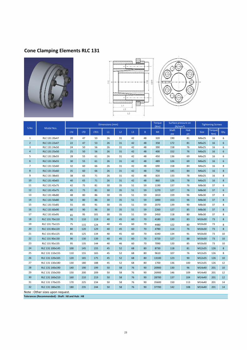
Cone Clamping Elements RLC 131
Centre the hub to the shaft
No axial displacement
Features
Centre the shaft to the hub.
No axial displacement between hub and shaft during clamping procedure due to fixed backstop point.
For shafts diameters between 20 mm up to 180 mm.
Application example
Backlash free connection of a cam disc to the drive shaft in a stepping gear in the material feed mechanism of a paper processing machine with a Cone Clamping Elements RLC 131.
Transmissible torques and axial forces
The transmissible torques or axial forces listed on page 23 are subject to the following tolerances, surface characteristics and material requirements. Please contact us in the case of deviations.
Tolerances
h8 for shaft diameter d
H8 for hub bore D
Surfaces
Average surface roughness at the contact surfaces between the shaft and the hub bore: Ra ≤ 1.6µm
Materials
The following apply to the shaft and the hub:
E-module ≥ 170kN/mm2
Installation
Please request our installation and operating instructions for Cone Clamping Elements RLC 131.
Simultaneous Transmission of torque and axial force
The transmissible torques M which are shown in the tables apply for forces F= 0kN and conversely, the indicated axial forces
F apply to torques M= 0 Nm. If torque and axial force are to be transmitted simultaneously, the transmissible torque and the
transmissible axial forces are reduced. Please refer to the technical points on pages 30 and 31.
Example for ordering
Cone Clamping Element RLC 131 for shaft diameter d = 40 mm:
RLC 131 40X65
22
21- 1
21- 2
Torque
(Nm)
Ød ØD ØD1 L1 L2 L3 B MtShaft
pw
Hub
pnSize
Torque(
Nm)Qty.
1 RLC 131 20x47 20 47 53 26 31 42 48 320 190 81 M6x25 16 6
2 RLC 131 22x47 22 47 53 26 31 42 48 358 172 81 M6x25 16 6
3 RLC 131 24x50 24 50 56 26 31 42 48 390 158 76 M6x25 16 6
4 RLC 131 25x50 25 50 56 26 31 42 48 400 152 76 M6x25 16 6
5 RLC 131 28x55 28 55 61 26 31 42 48 450 136 69 M6x25 16 6
6 RLC 131 30x55 30 55 61 26 31 42 48 489 126 69 M6x25 16 6
7 RLC 131 32x60 32 60 66 26 31 42 48 690 158 84 M6x25 16 8
8 RLC 131 35x60 35 60 66 26 31 42 48 750 145 84 M6x25 16 8
9 RLC 131 38x65 38 65 71 26 31 42 48 820 133 78 M6x25 16 8
10 RLC 131 40x65 40 65 71 26 31 42 48 860 126 78 M6x25 16 8
11 RLC 131 42x75 42 75 81 30 35 51 59 1190 137 76 M8x30 37 6
12 RLC 131 45x75 45 75 81 30 35 51 59 1270 127 76 M8x30 37 6
13 RLC 131 48x80 48 80 86 30 35 51 59 1810 159 96 M8x30 37 8
14 RLC 131 50x80 50 80 86 30 35 51 59 1890 153 96 M8x30 37 8
15 RLC 131 55x85 55 85 91 30 35 51 59 2070 139 90 M8x30 37 8
16 RLC 131 60x90 60 90 96 30 35 51 59 2260 127 85 M8x30 37 8
17 RLC 131 65x95 65 95 101 30 35 51 59 2450 118 80 M8x30 37 8
18 RLC 131 70x110 70 110 119 40 45 60 70 4180 130 83 M10x30 73 8
19 RLC 131 75x115 75 115 124 40 45 60 70 4480 122 80 M10x30 73 8
20 RLC 131 80x120 80 120 129 40 45 60 70 4780 114 76 M10x30 73 8
21 RLC 131 85x125 85 125 134 40 45 60 70 6340 134 91 M10x30 73 10
22 RLC 131 90x130 90 130 139 40 45 60 70 6720 127 88 M10x30 73 10
23 RLC 131 95x135 95 135 144 40 46 60 70 7090 120 85 M10x30 73 10
24 RLC 131 100x145 100 145 155 45 52 68 80 8730 118 81 M12x35 126 8
25 RLC 131 110x155 110 155 165 45 52 68 80 9610 107 76 M12x35 126 8
26 RLC 131 120x165 120 165 175 45 52 68 80 13100 123 90 M12x35 126 10
27 RLC 131 130x180 130 180 188 45 52 68 80 1700 136 100 M12x35 126 12
28 RLC 131 140x190 140 190 199 50 58 76 90 20900 130 96 M14x40 201 10
29 RLC 131 150x200 150 200 209 50 58 76 90 26900 146 109 M14x40 201 12
30 RLC 131 160x210 160 210 219 50 58 76 90 28700 137 104 M14x40 201 12
31 RLC 131 170x225 170 225 234 50 58 76 90 35600 150 113 M14x40 201 14
32 RLC 131 180x235 180 235 244 50 58 76 90 37700 142 108 M14x40 201 14
Cone Clamping Elements RLC 131
Tolerances (Recommended) - Shaft : h8 and Hub : H8
Note : Other sizes upon request.
S.No Modal Nos.
Surface pressure on
(N/mm²)Tightening ScrewsDimensions (mm)
23

Cone Clamping Elements RLC 132
Centre the hub to the shaft
Short axial width
Features
Centre the shaft to the hub.
Short axial width.
For shafts diameters between 20 mm up to 200 mm.
Application example
Backlash free connection of a belt pulley to the drive shaft with a Cone Clamping Elements RLC132. The Cone Clamping Element also centre the pulley to the shaft. The compact Cone Clamping Element is a cost-efficient solution especially for applications with low space requirements.
Transmissible torques and axial forces
The transmissible torques or axial forces listed on page 25 are subject to the following tolerances, surface characteristics and material requirements. Please contact us in the case of deviations.
Tolerances
h8 for shaft diameter d
H8 for hub bore D
Surfaces
Average surface roughness at the contact surfaces between the shaft and the hub
bore: Ra ≤ 1.6µm
Materials
The following apply to the shaft and the hub:
E-module ≥ 170kN/mm2
Installation
Please request our installation and operating instructions for Cone Clamping Elements RLC 132.
Simultaneous Transmission of torque and axial force
The transmissible torques M which are shown in the tables apply for forces F= 0kN and conversely, the indicated axial forces F apply to torques M= 0 Nm. If torque and axial force are to be transmitted simultaneously, the transmissible torque and the transmissible axial forces are reduced. Please refer to the technical points on pages 30 and 31.
Example for ordering
Cone Clamping Element RLC 132 for shaft diameter d = 80 mm:
RLC 132 80X120
24
23- 1
23- 2

Torque
(Nm)
Ød ØD L1 L2 L3 B MtShaft
pw
Hub
pnSize
Torque(
Nm)Qty.
1 RLC 132 20x47 20 47 17 22 28 34 410 372 158 M6x20 14 6
2 RLC 132 22x47 22 47 17 22 28 34 450 338 158 M6x20 14 6
3 RLC 132 24x50 24 50 17 22 28 34 490 310 149 M6x20 14 6
4 RLC 132 25x50 25 50 17 22 28 34 510 297 149 M6x20 14 6
5 RLC 132 28x55 28 55 17 22 28 34 570 265 135 M6x20 14 6
6 RLC 132 30x55 30 55 17 22 28 34 610 248 135 M6x20 14 6
7 RLC 132 32x60 32 60 17 22 28 34 880 310 165 M6x20 14 8
8 RLC 132 35x60 35 60 17 22 28 34 960 283 165 M6x20 14 8
9 RLC 132 38x65 38 65 17 22 28 34 1000 261 152 M6x20 14 8
10 RLC 132 40x65 40 65 17 22 28 34 1100 248 152 M6x20 14 8
11 RLC 132 42x75 42 75 20 25 33 41 2070 357 200 M8x25 30 8
12 RLC 132 45x75 45 75 20 25 33 41 2220 333 200 M8x25 30 8
13 RLC 132 48X80 48 80 20 24 33 41 2500 320 200 M8x25 32 8
14 RLC 132 50x80 50 80 20 24 33 41 2600 320 200 M8x25 32 8
15 RLC 132 55x85 55 85 20 24 33 41 2900 309 200 M8x25 34 8
16 RLC 132 60x90 60 90 20 24 33 41 3100 300 200 M8x25 35 8
17 RLC 132 65x95 65 95 20 24 33 41 3400 287 196 M8x25 35 8
18 RLC 132 70x110 70 110 24 29 40 50 6000 314 200 M10x30 65 8
19 RLC 132 75x115 75 115 24 29 40 50 6400 307 200 M10x30 68 8
20 RLC 132 80x120 80 120 24 29 40 50 6800 300 200 M10x30 70 8
21 RLC 132 85x125 85 125 24 29 40 50 8340 294 200 M10x30 59 10
22 RLC 132 90x130 90 130 24 29 40 50 9180 289 200 M10x30 61 10
23 RLC 132 95x135 95 135 24 29 40 50 10000 284 200 M10x30 64 10
24 RLC 132 100x145 100 145 26 31 44 56 12000 290 200 M12x30 110 8
25 RLC 132 110x155 110 155 26 31 44 56 13000 282 200 M12x30 115 8
26 RLC 132 120x165 120 165 26 31 44 56 16000 275 200 M12x30 112 9
27 RLC 132 130x180 130 180 34 39 52 64 23000 277 200 M12x30 115 12
28 RLC 132 140x190 140 190 34 39 54 68 25000 271 200 M14x40 185 9
29 RLC 132 150x200 150 200 34 39 54 68 30000 267 200 M14x40 185 10
30 RLC 132 160x210 160 210 34 39 54 68 37600 262 200 M14x40 162 12
31 RLC 132 170x225 170 225 44 49 64 78 41300 238 130 M14x40 185 12
32 RLC 132 180x235 180 235 44 49 64 78 48400 224 125 M14x40 185 12
33 RLC 132 190x250 190 250 44 49 64 78 64100 263 145 M14x40 185 15
34 RLC 132 200x260 200 260 44 49 64 78 67500 252 145 M14x40 185 15
Cone Clamping Elements RLC 132
Tolerances (Recommended) - Shaft : h8 and Hub : H8
Tightening ScrewsSurface pressure on
(N/mm²)
Note: Other size upon request
S.No Modal Nos.
Dimensions (mm)
25

Cone Clamping Elements RLC 133
Centre the hub to the shaft
Short axial width with fixed backstop point
Features
Centre the shaft to the hub.
Short axial width.
No axial displacement between hub and shaft during clamping procedure due to fixed backstop point.
For shafts diameters between 20 mm up to 200 mm.
Application example
Backlash free connection of a timing belt pulley to the drive shaft with a Cone Clamping Elements RLC 133.Due to the fixed backstop point, the timing belt pulley is not displaced axially during clamping. The Cone Clamping Element also centre’s the timing belt pulley to the shaft. The compact Cone Clamping Element is a cost-efficient solution especially for applications with low space requirements.
Transmissible torques and axial forces
The transmissible torques or axial forces listed on page 27 are subject to the following tolerances, surface characteristics and material requirements. Please contact us in the case of deviations.
Tolerances
h8 for shaft diameter d
H8 for hub bore D
Surfaces
Average surface roughness at the contact surfaces between the shaft and the hub bore: Ra ≤ 1.6µm
Materials
The following apply to the shaft and the hub:
E-module ≥ 170kN/mm2
Installation
Please request our installation and operating instructions for Cone Clamping Elements RLC 133.
Simultaneous Transmission of torque and axial force
The transmissible torques M which are shown in the tables apply for forces F= 0kN and conversely, the indicated axial forces F apply to torques M= 0 Nm. If torque and axial force are to be transmitted simultaneously, the transmissible torque and the transmissible axial forces are reduced. Please refer to the technical points on pages 30 and 31.
Example for ordering
Cone Clamping Element RLC 133 for shaft diameter d = 60 mm:
RLC 133 60X90
26
25- 1
25- 2

Torque
(Nm)
Ød ØD ØD1 L1 L2 L3 B MtShaft
pwHub pn Size
Torque(
Nm)Qty.
1 RLC 133 20x47 20 47 53 17 22 28 34 320 290 123 M6x20 16 6
2 RLC 133 22x47 22 47 53 17 22 28 34 350 264 123 M6x20 16 6
3 RLC 133 24x50 24 50 56 17 22 28 34 390 242 116 M6x20 16 6
4 RLC 133 25x50 25 50 56 17 22 28 34 400 232 116 M6x20 16 6
5 RLC 133 28x55 28 55 62 17 22 28 34 450 207 106 M6x20 16 6
6 RLC 133 30x55 30 55 62 17 22 28 34 489 193 106 M6x20 16 6
7 RLC 133 32x60 32 60 69 17 22 28 34 695 242 129 M6x20 16 8
8 RLC 133 35x60 35 60 69 17 22 28 34 760 221 129 M6x20 16 8
9 RLC 133 38x65 38 65 72 17 22 28 34 820 204 119 M6x20 16 8
10 RLC 133 40x65 40 65 72 17 22 28 34 869 193 119 M6x20 16 8
11 RLC 133 42X75 42 75 84 20 25 33 41 1580 273 153 M8x25 37 8
12 RLC 133 45x75 45 75 84 20 25 33 41 1700 255 153 M8x25 37 8
13 RLC 133 48X80 48 80 89 20 24 33 41 1810 239 143 M8x25 37 8
14 RLC 133 50x80 50 80 89 20 24 33 41 1890 229 143 M8x25 37 8
15 RLC 133 55x85 55 85 91 20 24 33 41 2070 208 135 M8x25 37 8
16 RLC 133 60x90 60 90 99 20 24 33 41 2260 191 127 M8x25 37 8
17 RLC 133 65x95 65 95 104 20 24 33 41 2450 176 121 M8x25 37 9
18 RLC 133 70x110 70 110 119 24 29 40 50 4180 217 138 M10x30 73 8
19 RLC 133 75x115 75 115 124 24 29 40 50 4480 203 132 M10x30 73 8
20 RLC 133 80x120 80 120 129 24 29 40 50 4780 190 127 M10x30 73 8
21 RLC 133 85x125 85 125 134 24 29 40 50 6340 224 152 M10x30 73 10
22 RLC 133 90x130 90 130 139 24 29 40 50 6720 211 146 M10x30 73 10
23 RLC 133 95x135 95 135 144 24 29 40 50 7090 200 141 M10x30 73 10
24 RLC 133 100x145 100 145 154 26 31 44 56 8730 204 140 M12x35 126 8
25 RLC 133 110x155 110 155 164 26 31 44 56 9610 185 131 M12x35 126 8
26 RLC 133 120x165 120 165 174 26 31 44 56 11700 191 150 M12x35 126 9
27 RLC 133 130x180 130 180 189 34 39 52 64 17000 180 130 M12x35 126 12
28 RLC 133 140x190 140 190 199 34 39 54 68 18800 172 140 M14x40 201 9
29 RLC 133 150x200 150 200 209 34 39 54 68 22400 178 134 M14x40 201 10
30 RLC 133 160x210 160 210 219 34 39 54 68 28700 201 153 M14x40 201 12
31 RLC 133 170x225 170 225 234 44 49 64 78 30500 146 105 M14x40 201 12
32 RLC 133 180x235 180 235 244 44 49 64 78 32300 138 106 M14x40 201 12
33 RLC 133 190x250 190 250 259 44 49 64 78 42700 163 120 M14x40 201 15
34 RLC 133 200x260 200 260 269 44 49 64 78 44900 155 119 M14x40 201 15
Cone Clamping Elements RLC 133
Tolerances (Recommended) - Shaft : h8 and Hub : H8
Note : Other sizes upon request.
S.No Modal Nos.
Surface pressure on
(N/mm²)Tightening ScrewsDimensions (mm)
27

Cone Clamping Elements RLC 200
Easy to release
Compact design
Features
Easy to release.
Compact design.
No axial displacement between hub and shaft during clamping procedure.
Extended tolerances for hub and shaft.
For shafts diameters between 20 mm up to 400 mm.
Application example
Backlash free connection of the two hubs of a flexible coupling with a Cone Clamping Elements RLC 200.The flexible coupling is situated in the later of a geared motor driving a roller conveyor.
Transmissible torques and axial forces
The transmissible torques or axial forces listed on page 29 are subject to the following tolerances, surface characteristics and material requirements. Please contact us in the case of deviations.
Tolerances
h9 for shaft diameter d
H9 for hub bore D
Surfaces
Average surface roughness at the contact surfaces between the shaft and the hub
bore: Ra ≤ 1.6µm
Materials
The following apply to the shaft and the hub:
E-module ≥ 170kN/mm2
Installation
Please request our installation and operating instructions for Cone Clamping Elements RLC 200.
Simultaneous Transmission of torque and axial force
The transmissible torques M which are shown in the tables apply for forces F= 0kN and conversely, the indicated axial forces F apply to torques M= 0 Nm. If torque and axial force are to be transmitted simultaneously, the transmissible torque and the transmissible axial forces are reduced. Please refer to the technical points on pages 30 and 31.
Example for ordering
Cone Clamping Element RLC 200 for shaft diameter d = 45 mm:
RLC 200 45X75
28
27- 1
27- 2

Torque
(Nm)
Ød ØD L1 L2 B MtShaft
pw
Hub
pnSize
Torque
(Nm)Qty.
1 RLC 200 20x47 20 47 17 20 26 273 240 102 M6x15 16 8
2 RLC 200 22x47 22 47 17 20 26 300 218 102 M6x15 16 8
3 RLC 200 24x50 24 50 17 20 26 330 200 96 M6x15 16 8
4 RLC 200 25x50 25 50 17 20 26 340 192 96 M6x15 16 8
5 RLC 200 28x55 28 55 17 20 26 570 257 131 M6x15 16 12
6 RLC 200 30x55 30 55 17 20 26 610 240 131 M6x15 16 12
7 RLC 200 32x60 32 60 17 20 26 660 225 120 M6x15 16 12
8 RLC 200 35x60 35 60 17 20 26 720 205 120 M6x15 16 12
9 RLC 200 38x65 38 65 17 20 26 970 236 138 M6x15 16 15
10 RLC 200 40x65 40 65 17 20 26 1000 225 138 M6x15 16 15
11 RLC 200 42x75 42 75 20 24 32 1580 264 148 M8x20 38 12
12 RLC 200 45x75 45 75 20 24 32 1700 246 148 M8x20 38 12
13 RLC 200 48x80 48 80 20 24 32 1800 231 139 M8x20 38 12
14 RLC 200 50x80 50 80 20 24 32 1890 222 139 M8x20 38 12
15 RLLC 200 55x85 55 85 20 24 32 2600 252 163 M8x20 38 15
16 RLC 200 60x90 60 90 20 24 32 2800 231 154 M8x20 38 15
17 RLC 200 65x95 65 95 20 24 32 3050 213 146 M8x20 38 15
18 RLC 200 70x110 70 110 24 28 38 5300 270 172 M10x25 75 15
19 RLC 200 75x115 75 115 24 28 38 5600 252 164 M10x25 75 15
20 RLC 200 80x120 80 120 24 28 38 6000 236 157 M10x25 75 15
21 RLC 200 85x125 85 125 24 28 38 6400 222 151 M10x25 75 15
22 RLC 200 90x130 90 130 24 28 38 6800 210 145 M10x25 75 15
23 RLC 200 95x135 95 135 24 28 38 8600 239 168 M10x25 75 18
24 RLC 200 100x145 100 145 26 32 44 11000 257 177 M12x30 130 15
25 RLC 200 110x155 110 155 26 32 44 12000 234 166 M12x30 130 15
26 RLC 200 120x165 120 165 26 32 44 14000 228 166 M12x30 130 16
27 RLC 200 130x180 130 180 34 38 50 19000 202 146 M12x35 130 20
28 RLC 200 140x190 140 190 34 38 50 22000 206 152 M12x35 130 22
29 RLC 200 150x200 150 200 34 38 50 26000 210 157 M12x35 130 24
30 RLC 200 160x210 160 210 34 38 50 30000 213 162 M12x35 130 26
31 RLC 200 170x225 170 225 38 44 58 35400 207 156 M14x40 200 22
32 RLC 200 180x235 180 235 38 44 58 40900 213 163 M14x40 200 24
33 RLC 200 190x250 190 250 46 52 66 50300 195 148 M14x45 200 28
34 RLC 200 200x260 200 260 46 52 66 56700 198 153 M14x45 200 30
35 RLC 200 220x285 220 285 50 56 72 72000 199 154 M16x50 300 26
36 RLC 200 240x305 240 305 50 56 72 90800 211 166 M16x50 300 30
37 RLC 200 260x325 260 325 50 56 72 108500 221 177 M16x50 300 34
38 RLC 200 280x355 280 355 60 66 84 137000 192 151 M18x60 410 32
39 RLC 200 300x375 300 375 60 66 84 165000 201 161 M18x60 410 36
40 RLC 200 320x405 320 405 72 78 98 229000 202 160 M20x70 590 36
41 RLC 200 340x425 340 425 72 78 98 243000 190 152 M20x70 590 36
42 RLC 200 360x455 360 455 84 90 112 320000 191 151 M22x80 790 36
43 RLC 200 380x475 380 475 84 90 112 337000 181 145 M22x80 790 36
44 RLC 200 400x495 400 495 84 90 112 355000 172 139 M22x80 790 36
Cone Clamping Elements RLC 200
Tolerances (Recommended) - Shaft : h9 and Hub : H9
Note : Other sizes upon request.
S.No Modal Nos.
Surface pressure on
(N/mm²)Tightening ScrewsDimensions (mm)
29

Technical points for Cone Clamping Elements:
Clamping screw tightening torque
The tightening torque MS listed in the tables must be achieved during assembly and must not be exceeded by more than 10%. If the indicated tightening torque MS is not achieved, the transmissible torque or axial force, as well as the contact pressure at the shaft and at the hub will be proportionally reduced compared to the values listed in the tables for M or F as well for Pw and PN. When the indicated tightening torque MS is undercut by more than 30%, please contact us
Design security
On page 5, the RYDON calculation method for determination of the preload forces according to common friction–coefficient fluctuations is explained. As already shown there, the transmissible torques M and axial forces F listed in the tables are calculated based on the minimum preload force FS, where as the required hub outer diameters Kmin are calculated based on the maximum preload force MS assumed in the table are exceeded by 10%.
The calculation for the elements RLC 200, assumes that the preload force of the clamping screws provided by the customer is distributed accordingly.
In the interest of the best design security, the following assumptions were made for the calculation of the Cone Clamping Elements:
Simultaneous transmission of torque and axial force
The transmissible torque M which are shown in the tables apply for axial forces F = 0 kN and conversely, the indicated axial forces F apply to torques M = 0 Nm. If torque and axial force are to be transmitted simultaneously, the transmissible torque and the transmissible axial force are reduced compared to the values listed in the tables for M and F.
For a given axial force FA, the reduced torque Mred is calculated as:
Mred = √M2-(FA*d/2)
2
For a given torque MA, the reduced axial force Fred is calculated as:
Fred = 2/d√M2 - MA
2
Bending moments
Where there is bending moments in addition to the torque MA or the axial force FA, the transmissible torque or transmissible axial force is reduced compared to the values for M or F as listed in the tables. Please contact us.
Hollow shafts
When clamping Cone Clamping Elements on hollow shafts, the tangential stress δtWi must not exceed the yield strength Re of the hollow shaft material.
δtWi =1.27*PW* 2
with 1-CW
2
CW= dwi
d
30
Size
Tightening torque for µk=0.1 MS (Nm)
8.8 10.9 12.9
M4 2.6 3.9 4.5
M5 5.2 7.6 8.9
M6 9 13.2 15.4
M8 21.6 31.8 37.2
M10 43 63 73
M12 73 108 126
M14 117 172 201
M16 180 264 309
M18 259 369 432
M20 363 517 605
M22 495 704 824
M24 625 890 1041
For Calculating Assumed preload force
for all series except RLA 200
M and F lower limit value FS
PW and PN Middle limit value F
Kmin Upper limit value FS

Technical points for Cone Clamping Elements:
Hub Design
For the different Cone Clamping Element series, the tables list the required hub width Nmin and the required hub outer diameter
Kmin hub. Thereby, the hub is to be arranged as seen in figure 30-1 for Cone Clamping Elements with a fixed backstop point.
When the actual load-bearing hub width NA is smaller than the required hub width Nmin and the yield strengths Re of the hub
material is known, the calculated approximately as follows:
Kmin = 1.2 * D*
H = ( Re *
NA )2
1.27*PN L1
When the hub width NA is known and the hub yield strength Re must be higher than the equivalent stress δV in the hub.
δV = 1.27*PN* L1
* √3+CN4
with
NA 1-CN2
CN = D
KA The load-bearing hub width NA in the application must not be smaller than the load-bearing width L1.
Formula Symbols
D = Shaft diameter (mm)
dWi = Inner hollow shaft diameter (mm)
D = Hub bore (mm)
F = Transmissible axial force according to table (kN)
FA = Maximum actual application axial force (kN)
Fred = Reduced axial force (kN)
FS = Preload force (kN)
KA = Hub outer diameter in the application (mm)
Kmin = Required hub outer diameter according to table or calculation (mm)
L1 = Load-bearing axial width according to table (mm)
M = Transmissible torque according to table (Nm)
MA = Maximum axial application torque (Nm)
Mred = Reduced torque (Nm)
MS = Screw tightening torque (Nm)
NA = Load-bearing hub width in the application (mm)
Nmin = Required hub width according to table (mm)
PN = Contact pressure at the hub according to table (N/mm
2)
PW = Contact pressure at the shaft according to table (N/mm
2)
Re = Hub material yield strength (N/mm2)
δtWi = Tangential stress in the hub (N/mm2)
δV = Equivalent stress in the hub (N/mm2)
CN, CW and H are reference values without units.
31
H - 1.25 with
H - 3
29- 1