table of contentsrydongroup.com/pdf/rydon_jawcoupling.pdf · · 2014-12-02table of contents...
TRANSCRIPT


Table of contents
Description of couplings 3
Coupling selection 4
Displacements 5
Selection of standard IEC motors 6
Properties of standard spiders 7
Hub designs 8
Cylindrical bores and spline bores 9
Inch bores and taper bores 10
Shaft coupling design-casted materials 11
Shaft coupling design-material steel 12
shaft coupling for taper clamping bush 13
Clamping ring hubs 14
Clamping hubs 15
Flange programme design AFN and BFN 16
Drop-out center design coupling type A-H 17
Drop-out center design coupling type S-H with SPLIT-hubs 18

Description of Coupling
RYDON jaw couplings are characterized by small dimensions, low weight and low mass moments of inertia
yet transmit high torques. Running quality and service life of the coupling are improved by accurate all-over
machining. Their application is ideal for transmitting torque while damping torsional vibrations and
absorbing shocks produced by the uneven operation of certain prime movers.
General Description
RYDON jaw couplings are torsionally flexible and designed for positive torque transmission. They are fail-
safe. Operational vibrations and shocks are efficiently dampened and reduced. The two congruent coupling
halves with concave claws on the inside are periphally offset in relation to one another by half a pitch. In
addition, they are designed in such a way as to enable an involute spider to be located between them. The
teeth of the spider are crowned to avoid edge pressure if the shafts are misaligned. RYDON jaw couplings
are capable of compensating for axial, radial and angular displacements of the shafts to be connected.
Performance
In contrast to other flexible couplings, the intermediate members of which are subject to bending stress and
are therefore prone to earlier wear, the flexible teeth of RYDON jaw couplings are subject to pressure only.
This gives the additional advantage of the individual teeth being able to accept considerably higher loads.
The elastomer parts show deformation with load and excessive speeds. Sufficient space for expansion
should be ensured (see drawing-deformation with load).The maximum torsion angle with RYDON jaw
couplings of any size amounts to 5°. They can be fitted both horizontally and vertically.
Curved Jaw Design
•Three piece design that is easy to assemble
•The curved jaw design incorporates both radial and axial curvature (crowning) to the elastomer
•Hubs are offered in steel, aluminium, cast iron and cast iron
•Three different urethane elastomers available
•No metal to metal contact and no lubrication required
•Fail safe design due to jaw in compression design (continues to function after the elastomer fails)
Spiders
RYDON has employed thermoplastic polyurethane material for its spiders. The improved thermoplastic
polyurethane material is resistant to significantly higher temperatures and has a considerably longer service life
than polyurethane material. Up to size 180, inclusive single-parted spiders are used as standard.
Properties
•Urethane spiders provide high abrasion resistance and elasticity, along with good damping characteristics
•The spiders are offered in a variety of shore hardnesses, each providing a different level of torque capacity, damping and chemical resistance
•The standard curved jaw spider design has a hole in the center to accommodate small between shaft end measurements
•The spiders have a temperature capacity of 212°F
•The curved jaw spider’s urethane material also resists oil, dirt, sand, grease, moisture, many solvents as well as atmospheric effects of ozone.

Coupling Selection
The RYDON jaw coupling is selected in accordance with DIN 740 part 2. The coupling has to be dimensioned in a way that the
permissible coupling load is not exceeded in any operating condition. For this purpose the actual loads have to be compared to the
permissible parameters of the coupling. The torques TKN/TKmax mentioned refer to the spider. The shaft-hub-connection has to be
investigated by the customer.
1. Drives without periodical torsional vibrations
e.g. centrifugal pumps, fans, screw compressors, etc. The
coupling is selected taking into account the rated torques TKN and
maximum torque TK max.
1.1 Load produced by rated torque
Taking into consideration the ambient
temperature, the permissible rated
torque TKN of the coupling has to
correspond at least to the rated torque
TN of the machine.
1.2 Load produced by torque shocks
The permissible maximum torque of the
coupling has to correspond at least to
the total of peak torque TS and the rated
torque TN of the machine, taking into
account the shock frequency Z and the
ambient temperature. This applies in
case if the rated torque TN of the
machine is at same time subject to
shocks. Knowing the mass distribution,
shock direction and shock mode, the
peak torque TS can be calculated.
Description Symbol Definition or explanation Rated torque of
coupling
TKN Torque that can continuously be
transmitted over the entire permissible
speed range
Maximum torque of
coupling
TK max Torque that can be transmitted as
dynamic load ≥ 105 times or 5x10⁴ as
vibratory load, respectively, during the
entire operating life of the coupling
Vibratory torque of
coupling
TKW Torque amplitude of the permissible
periodical torque fluctuation with a
frequency of 10Hz and a basic load of
TKN or dynamic load up to TKN,
respectively
Damping power of
coupling
PKW Permissible damping power with an
Pambient temperature of +30°C
Rated torque of
machine
TN Stationary rated torque on the coupling
Rated torque of
driving side
TAN Rated torque of machine, calculated
from rated power and rated speed
Rated torque of load
side
TLN Maximum figure of the load torque
calculated from power and speed
Peak torque of
machine
TS Peak torque on the coupling
Peak torque on the
driving side
TAS Peak torque with torque shock on the
driving side, e.g. breakdown torque of
the electric motor
2. Drives with periodical torsional vibrations
For drives subject to high torsional vibrations, e.g. diesel engines,
piston compressors, piston pumps, generators, etc., it is necessary to
perform a torsional vibration calculation to ensure a safe operation.
2.1 Load produced by rated torque
Taking into account the ambient temperature, the permissible
rated torque TKN of the coupling has to correspond at least to the
rated torque TN of the machine.
2.2 Passing through the resonance range
Taking into account the temperature, the peak torque TS
arising when the resonance range is run through must not
exceed the maximum torque TKmax of the coupling.
2.2 Load produced by vibratory torque shocks
Taking into account the ambient temperature, the permissible
vibratory torque TKW of the coupling must not be exceeded by the
highest periodical vibratory torque TW with operating speed. For
higher operating frequencies f>10, the heat produced by damping
power PW. For higher operating frequencies f>10, the heat
produced by damping in the elastomer part is considered as
damping power PW.
Description Symbol Definition or explanation Peak torque of load side TLS Peak torque with torque shock on
load side, e.g. braking
Vibratory torque of
machine
TW Amplitude of the vibratory torque
effective on the coupling
Damping power of the
machine
PW Damping power which is effective
on the coupling due to the load
produced by the vibratory torque
Moment of inertia of
driving side
JA Total of moments of inertia
existing on the driving or load
side referring to the coupling side Moment of inertia of
load side
JL
Rotational inertia
coefficient of driving
side
MA Factor taking into account the
mass distribution with shocks and
vibrations produced on the driving
or load side
MA=JL/(JA+JL) ML=JA/(JA+JL) Rotational inertia
coefficient of load side
ML
Screw tightening torque TA Tightening torque of screw
TN[Nm]=9550*P[kW]/n[rpm]
TKN≥TN*S
t
TKN≥TN*St
TKmax.≥Ts*St
TKW≥TW*St
TK[max]≥TS*Sz*St+TN*St
Drive-sided shock
Ts=TAS*MA*SA
Load-sided shock
Ts=TLS*ML*SL
MA=JL/(JA+JL)MA=JL/(JA+JL) PKW≥PW

Coupling Selection
Service factor temperature St -50°C -30°C+30°C +40°C +50°C +60°C +70°C +80°C +90°C +100°C +110°C +120°C
T-PUR 1.0 1.0 1.1 1.2 1.3 1.5 1.6 1.8 2.1 2.5 3.0
PUR - 1.0 1.2 1.3 1.4 1.6 1.8 2.2 - - - For the selection with PEEK spider a temperature factor is not necessary.
Service Sz factor for starting frequency Service factor SA/SL for shocks
Starting frequency/h 100 200 400 800
SA/SL
gentle shocks 1.5
Sz 1.0 1.2 1.4 1.6
average shocks 1.8
heavy shocks 2.5
Displacements
Displacements for spider 92, 95/98 Shore-A Size 14 19 24 28 38 42 48 55 65 75 90 100 110 125 140 160 180
Max. axial
displacement ∆Ka
[mm] -0.5
+1
-0.5
+1.2
-0.5
+1.4
-0.7
+1.5
-0.7
+1.8
-1.0
+2.0
-1.0
+2.1
-1.0
+2.2
-1.0
+2.6
-15
+3.0
-1.5
+3.4
-1.5
+3.8
-2.0
+4.2
-2.0
+4.6
-2.0
+5.0
-2.5
+5.7
-3.0
+6.4
Max. radial
displacement with
n=1500rpm
∆Kw[degree] 0.17 0.20 0.22 0.25 0.28 0.32 0.36 0.38 0.42 0.48 0.50 0.52 0.55 0.60 0.62 0.64 0.68
Max. angular
displacement with
n=1500 rpm
∆Kw[degree] 1.2 1.2 0.9 0.9 1 1 1.1 1.1 1.2 1.2 1.2 1.2 1.3 1.3 1.2 1.2 1.2
∆Kw [mm] 0.67 0.82 0.85 1.05 1.35 1.7 2 2.3 2.7 3.3 4.3 4.8 5.6 6.5 6.6 7.6 9
Displacements for spider 64 Shore-D
Size 14 19 24 28 38 42 48 55 65 75 90 100 110 125 140 160 180
Max. axial
displacement ∆Ka
[mm] -0.5 +1
-0.5 +1.2
-0.5 +1.4
-0.7 +1.5
-0.7 +1.8
-1.0 +2.0
-1.0 +2.1
-1.0 +2.2
-1.0 +2.6
-15 +3.0
-1.5 +3.4
-1.5 +3.8
-2.0 +4.2
-2.0 +4.6
-2.0 +5.0
-2.5 +5.7
-3.0 +6.4
Max. radial
displacement with
n=1500rpm
∆Kw[degree] 0.11 0.13 0.15 0.18 0.21 0.23 0.25 0.27 0.30 0.34 0.36 0.37 0.40 0.43 0.45 0.46 0.49
Max. angular
displacement with
n=1500 rpm
∆Kw[degree] 1.1 1.1 0.8 0.8 0.9 0.9 1 1 1.1 1.1 1.1 1.1 1.2 1.2 1.1 1.1 1.1
∆Kw [mm] 0.57 0.76 0.76 0.90 1.25 1.40 1.80 2.00 2.50 3.00 3.80 4.30 5.30 6.00 6.10 7.10 8.00
The above-mentioned figures of displacement of flexible jaw couplings are standard values taking into account the load of the
coupling up to the rated torque TKN and an operating speed n=1500rpm along with an ambient temperature of +30°C.
The displacement figures may only be used individually – if they arise simultaneously, they must be used proportionally. Care
should be taken to maintain the distance dimension E accurately in order to allow for axial clearance of the coupling while in
operation.
Lmax.=L+∆Ka ∆Kw[mm]=Lmax-Lmin

Selection of standard IEC motors
RYDON jaw couplings for standard IEC motors, protection class IP 54/IP 55 (Spider 92 Shore A)
A.C. motor 50Hz Motor output
n=3000rpm
2-pole
Jaw
Coupling
Size
Motor output
n=1500rpm
4-pole
Jaw
Coupling
Size
Motor output
n=1000rpm
6-pole
Jaw
Coupling
Size
Motor output
n=750rpm
8-pole
Jaw
Coupling
Size Size
Shaft end dxl
[mm]
2-pole 4,6,8
pole
Output
P [kW]
Torque
T [Nm]
Output
P [kW]
Torque
T [Nm]
Output
P [kW]
Torque
T [Nm]
Output
P [kW]
Torque
T [Nm]
56 9x20 0.09 0.32
9 0.06 0.43
9 0.037 0.43
9
0.12 0.41 0.09 0.64 0.045 0.52
63 11x23 0.18 0.62
14
0.12 0.88
14
0.06 0.7
14
0.25 0.86 0.18 1.3 0.09 1.1
71 14x30 0.37 1.3 0.25 1.8 0.18 2 0.09 1.4
14 0.55 1.9 0.37 2.5 0.25 2.8 0.12 1.8
80 19x40 0.75 2.5
19
0.55 3.7
19
0.37 3.9
19
0.18 2.5
19 1.1 3.7 0.75 5.1 0.55 5.8 0.25 3.5
90S 24x50
1.5 5 1.1 7.5 0.75 8 0.37 5.3
90L 2.2 7.4 1.5 10
24
1.1 12
24
0.55 7.9
24 100L 28x60
3 9.8 24
2.2 15 1.5 15
0.75 11
3 20 1.1 16
112M 4 13 4 27 2.2 22 1.5 21
132S
38x80
5.5 18
28
5.5 36
28
3 30
28
2.2 30
28 7.5 25
132M 7.5 49 4 40 3 40
5.5 55
160M 42x110
11 36
38
11 72
38 7.5 75
38
4 54
38 185 49 5.5 74
160L 18.5 60 15 98 11 109 7.5 100
180M 48x110
22 71
42
18.5 121
42
42
42 180L 22 144 15 148 11 145
200L 55x110 30 97 30 196 18.5 181 15 198
37 120 22 215
225S 55x110 60x140
37 240 48 18.5 244 48
225M 45 145 45 292 55
30 293 55 22 290 55
250M 60x140 65x140 55 177 48 55 356 37 361 65
30 392 65
280S
65x140
75x140 75 241
55 75 484 65 45 438 37 483 65
280M 90 289 90 581
75
55 535
75
45 587 75
315S
80x170
110 353
65
110 707 75 727 55 712
315M 132 423 132 849 90 873 75 971
90 315L
160 513 160 1030
90
110 1070
90
90 1170
200 641
75
200 1290 132 1280 110 1420
85x170
160 1550 132 1710
315 250 802 250 1600 200 1930 160 2070
100 315 1010
90
315 2020
100
250 2410 100 200 2580
355 75x140 95x170
355 1140 355 2280
400 1280 400 2570 315 3040 110 250 3220 110
500 1600 500 3210 110 400 3850 125
315 4060 125
400 80x170 110x210
560 1790 560 3580 125
450 4330 355 4570
140 630 2020
100
630 4030 500 4810
140
400 5150
710 2270 710 4540
140
560 5390 450 5790
450 90x170 120x210
800 5120 800 5120 630 6060 500 6420
160 900 2880 110
900 5760 710 6830 160
560 7190
1000 3200 1000 6400 160 800 7690 630 8090
The arrangement of couplings is valid for an ambient temperature of up to +30°C. for the selection there is a
minimum safety factor of 2 of the max. coupling torque (TKmax.). Drives with periodical torque curves must be
selected according to DIN 740 part 2.

Properties of our standard spiders
Spider type (hardness Shore) 92 Shore-A (T-PUR) 92 Shore-A
Size 14 to 180 14 to 90
Material Thermoplastic polyurethane (T-PUR) Polyurethane (PUR)
Permanent temperature range Continous temperature Maximum temperature short time
-50°C to +120°C -50°C to +150°C
-40°C to +90°C -50°C to +120°C
Properties
Significantly longer service life. Very good temperature resistance. Improved damping of vibrations. Good damping, average elasticity. Suitable for all hub materials.
Good damping, average elasticity. Suitable for all hub materials.
Spider type (hardness Shore) 98 Shore-A (T-PUR) 98 Shore-A
Size 14 to 180 14 to 90
Material Thermoplastic polyurethane (T-PUR) Polyurethane (PUR)
Permanent temperature range Continous temperature Maximum temperature short time
-50°C to +120°C -50°C to +150°C
-30°C to +90°C -40°C to +120°C
Properties
Significantly longer service life. Very good temperature resistance. Improved damping of vibrations. Transmission of high torques with average damping. Recommended hub material: steel, GJL and GJS.
Transmission of high torques with average damping. Recommended hub material: steel, GJL and GJS.
Spider type (hardness Shore) 64 Shore-D (T-PUR) 64 Shore-D
Size 14 to 180 14 to 90
Material Thermoplastic polyurethane (T-PUR) Polyurethane (PUR)
Permanent temperature range Continous temperature Maximum temperature short time
-50°C to +120°C -50°C to +150°C
-30°C to +110°C -30°C to +130°C
Properties
Significantly longer service life. Very good temperature resistance. Improved damping of vibrations. Transmission of high torques with average damping. Recommended hub material: steel, GJL and GJS.
Transmission of very high torques with low damping. Suitable for displacing critical speeds. Resistant to hydrolysis. Recommended hub material:steel and GJS
Size 14 Size 19 Size 24-65 Size 75-160 Size 180

Hub designs
Due to the numerous applications of jaw coupling for many different applications and mounting situations, this
coupling system is available with various hub designs. These designs mainly differ in that they offer either positive
or frictionally engaged connections, but mounting situations like, for example, gear shafts with integrated
transmission cams or similar applications are covered, too.
Shaft coupling-hub with keyway and
fixing screw
Positive locking power transmission,
permissible torque depending on the
permissible surface pressure. Not suitable for
backlash-free power transmission with
heavily reversing operation.
Shaft coupling-Hub without keyway, with
fixing screw Non-positive torque transmission for crimp
and glued connections.
Clamping ring hub
Integrated frictionally engaged shaft-hub-
connection for the transmission of higher
torques. Screwing on elastomer side. Suitable
for high speeds.
Clamping ring hubs
Design similar to above, except for clamping
screws externally.
Split hub without feather keyway
Split hub made of cast iron. Frictionally
engaged, backlash-free shaft-hub-connection.
Transmittable torques depending on bore
diameter.
TB 1 hub/ TB 2 hub
Coupling hub for taper clamping bushes. TB1
screwed on cam side. TB2 screwed externally.
Clamping hub, single slotted, without
keyway
Frictionally engaged, backlash-free shaft-hub-
connection. Transmittable torques depending
on bore diameter
Clamping hub, single slotted, with keyway
Positive locking power transmission with
additional frictionally engaged condition. The
frictionally engaged condition prevents or
reduces reverse backlash, respectively. Surface
pressure of the feather key connection is prevented.
Clamping hub type H without feather
keyway
Frictionally engaged, backlash-free shaft-hub-
connection for radial assembly of coupling.
Transmittable torques depend on the bore
diameter.
Clamping hub type H with feather keyway
Positive locking power transmission with
additional friction fit for radial assembly of
coupling. The frictionally engaged condition prevents
or reduces reverse backlash, respectively. Surface
pressure of the feather key connection is prevented.
Split hub with feather keyway
Split hub made of cast iron. Positive locking
power transmission with additional frictionally
engaged condition. The frictionally engaged
condition prevents or reduces reverse backlash,
respectively. The surface pressure of the feather
key connection is reduced.
Design 3Na + 4N
Driving flange with C-flange
For type AFN and BFN.
With type AFN the spider can be replaced
while being assembled without having to
disassemble the driving and driven side.

Cylindrical bores and spline bores
Stock programme cylindrical finish bore [mm] H7 keyway to DIN 6885 sheet 1 [JS9] with thread for setscrew Size/
Material un-bored Ø6 Ø8 Ø9 Ø10 Ø11 Ø12 Ø14 Ø15 Ø16 Ø17 Ø18 Ø19 Ø20 Ø 22 Ø24 Ø25 Ø28 Ø30 Ø32 Ø35 Ø38 Ø40 Ø42 Ø45 Ø48 Ø50 Ø55 Ø60 Ø65 Ø70 Ø75 Ø80 Ø85 Ø90 Ø100
14 Al-H • • • • • • • • • •
19 Al-D • • • • • • • • • • • • •
St • • • • • • • • • • • • • • •
24 Al-D • • • • • • • • • • • • • • •
St • • • • • • • • • • • • • • • •
28 Al-D • • • • • • • • • • • • • •
St • • • • • • • • • • • • • • • •
38 GJL • • • • • • • • • • • • • • • • • St • • • • • • • • • • • •
42 GJL • • • • • • • • • • • • • • • • St • • • • • • • • • • • • •
48 GJL • • • • • • • • • • • • • • • St • • • • • • • • • • • •
55 GJL • • • • • • • • • • • • • • • St • • • • • • • • • • •
65 GJL • • • • • • • • • • • • • St • • • • • • • • • •
75 GJL • • • • • • • • • • • • St • • • • • • • • •
90 GJL • • • • • • • • • • • St • • • • • • • •
Basic programme SAE involute spline
Spline code Size
Pitch circle Pitch No. of teeth Angle Spline code Size
Pitch circle Pitch
No. of teeth Angle
PH-S 5/8" 14.28 16/32 9 30° PS-S 1 1/2" 35.98 12/24 17 30°
PI-S 3/4" 17.46 16/32 11 30° PD-S 1 1/2" 36.51 16/32 23 30°
PB-S 7/8" 20.63 16/32 1 30° PE-S 1 3/4" 42.86 16/32 27 30°
PB-BS 1" 23.81 16/32 15 30° PK 1 3/4" 41.275 8/16 13 30°
PJ 1 1/8" 26.98 16/32 17 30° PT-C ¹⁾ 2" 47.625 8/16 15 30°
PC-S 1 1/4" 29.63 12/24 14 30° PQ-C ¹⁾ 2 1/4" 53.975 8/16 17 30°
PA-S 1 3/8" 33.33 16/32 21 30°
Basic programme spline bores to DIN 5482
Size Pitch circle Pitch No. of teeth Profile correction Size Pitch circle Pitch No. of teeth Profile correction
A 17x14 14.40 1.6 9 +0.600 ²⁾ A 35x31 31.50 1.75 18 0.676
A 20x17 19.20 1.6 12 -0.2 A 40x36 38.00 1.9 20 0.049
A 25x22 22.40 1.6 14 +0.550 A 45x41 44.00 2 22 0.181
A 28x25 26.25 1.75 15 +0.302 A 50x45 48.00 2 24 0.181
A 30x27 28.00 1.75 16 +0.327
Basic programme spline bores to DIN 5480
Spline code Pitch circle Pitch No. of teeth Spline code Pitch circle Pitch No. of teeth
20x1x18x7H 18.0 1 18 40x2x18x8H 36 2 18
20x1.25x14x7H 17.5 1.25 14 45x2x21x7H 41 2 21
25x1.25x18x7H 22.5 1.25 18 48x2x22x9H 44 2 22
28x1.25x21x7H 26.25 1.25 21 50x2x24x8H 48 2 24
30x2x14x7H 26.0 2 14 60x2x28x8H 56 2 28
32x2x14x8H 28.0 2 14 75x3x24x7H 72 3 24
35x2x16x8H 32.0 2 16 80x3x25x8H 75 3 25
Basic programme spline bores to DIN 9611
Size Width of keyway No. of teeth Tip circle Root circle
1 3/8" 8.69 6 34.93 29.65 Spline clamping hubs are often adapted to the shafts of hydraulic pumps/hydraulic motors.
1) For clamping hubs only, for plug-in hubs use code PT or PQ.
2) Profile correction different from DIN.

Inch bores and taper bores
Stock programme inch bores
Size 19 24 28 38 42 48 55 65 75 90
Material
St St St St St St St St St St Code Ød Ød Inch b +0.05 t2 +0.2
Tb 9.5+0.03
3/8 3.17 11.1 DNB 11.11
M7 7/16 2.4 12.5
T 12.69 H7
1/2 4.75 14.6 Ta 12.7
+0.03 1/2 3.17 14.3 • •
DNC 3.45 H7
1 7/32 3.17 14.9 Do 14.29
+0.03 9/16 3.17 15.6
E 15.87+0.03
5/8 3.17 17.5 Es 15.88
+0.03 5/8 4 17.7 • • •
Ed 15.87+0.03
5/8 4.75 18.1 • • DNH 17.465
H7 11/16 4.75 19.6
Ad 19.02+0.03
3/4 3.17 20.7
A 19.05+0.03
3/4 4.78 21.3 • • • • Gs 22.22
+0.03 7/8 4.78 24.4 •
G 22.22+0.03
7/8 4.75 4.7 • • • • • F 22.22
+0.03 7/8 6.38 25.2 • • • • •
Gd 22.225 M7
7/8 4.76 24.7 • Gf 23.80
+0.03 1 5/16 6.35 26.8
Bs 25.38+0.03
1 6.37 28.3 • • • • H 25.40
+0.03 1 4.78 27.8
Hs 25.40+0.03
1 6.35 28.7 • R 26.95
+0.03 1 1/16 4.78 29.3
Sa 28.575 M7
1 1/8 6.35 31.7 • • Sb 28.58
+0.03 1 1/8 6.35 31.5 • •
Sd 28.58+0.03
1 1/8 7.93 32.1
Js 31.75+0.03
1 1/4 6.35 34.6
K 31.75K7
1 1/4 7.93 35.5 • • • • • • Ma 34.925
M7 1 3/8 7.93 38.7 •
RH1 34.93 M7
1 3/8 9.55 37.8
Cb 36.50+0.03
1 7/16 9.55 40.9
Ca 38.07+0.03
1 1/2 7.93 42
C 38.07+0.03
1 1/2 9.55 42.5 • • • • • • • Nb 41.275
M7 1 5/8 9.55 45.8
• •
Ls 44.42+0.03
1 3/4 9.55 48.8
L 44.45K7
1 3/4 11.11 49.4 • • Lu 47.625
M7 1 7/8 12.7 53.5 •
Da 49.20+0.03
1 15/16 12.7 55
Ds 50.77+0.03
2 12.7 56.4 • D 50.80
+0.03 2 12.7 55.1
Pa 53.975 M7
2 1/8 12.7 60 • U 57.10
+0.03 2 1/4 12.7 62.9
Ub 60.325 M7
2 3/8 15.875 67.6
Wd 85.725 M7
3 3/8 22.225 95.8
Wf 92.075 M7
3 5/8 22.225 101.9
Basic programme taper 1:8 Basic programme taper 1:5
Code d+0.05 (d2) bJS9 t2 +0.1 IK Code d+0.05 (d2) bJS9 t2
+0.1 IK N/ 1 9.7 7.575 2.4
+0.05 10.85 17 A-10 9.85 7.55 2
JS9 1 11.5
N/ 1c 11.6 9.5375 3 JS9
12.9 16.5 B-17 16.85 13.15 3 JS9
1.8 18.5 N/ 1e 13 10.375 2.4
+0.05 13.8 21 C-20 19.85 15.55 4
JS9 2.2 21.5
N/ 1d 14 11.813 3 JS9
15.5 17.5 Cs-22 21.95 17.65 3 JS9
1.8 21.5 N/ 1b 14.3 11.8625 3.2
+0.05 5.65 19.5 D-25 24.85 19.55 5
JS9 2.9 26.5
N/ 2 17.287 14.287 3.2 +0.05
18.24 24 E-30 29.85 23.55 6 JS9
2.6 31.5 N/ 2a 17.287 14.287 4
JS9 18.94 24 F-35 34.85 27.55 6
JS9 2.6 36.5
N/ 2b 17.287 14.287 3 JS9
18.34 24 G-40 39.85 32.85 6 JS9
2.6 35 N/ 3 22.002 18.502 4
JS9 3.4 28
N/ 4 25.463 20.963 4.78 +0.05
27.83 36
N/ 4b 25.463 20.963 5 JS9
28.23 36 N/ 4a 27 22.9375 4.78
+0.05 28.8 32.5
N/ 4g 28.45 23.6375 6 JS9
29.32 38.5 N/ 5 33.176 27.676 4.78
+0.05 35.39 44
N/ 5a 33.176 27.676 7 JS9
35.39 44
For code N/6 and N/6a keywidth parallel to the taper Basic programme taper 1:10
Code d+0.05 (d2) bJS9 t2 +0.1 IK
CX 19.95 16.75 5
JS9 22.08 32
DX 24.95 20.45 6
JS9 26.68 45
EX 29.75 24.75 8
JS9 31.88 50
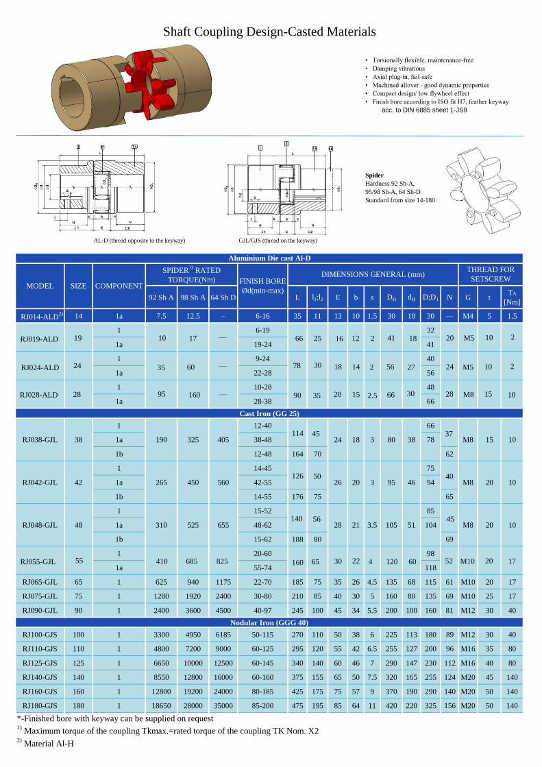
• Torsionally flexible, maintenance-free
• Damping vibrations
• Axial plug-in, fail-safe
• Machined allover - good dynamic properties
• Compact design/ low flywheel effect
• Finish bore according to ISO fit H7, feather keyway
acc. to DIN 6885 sheet 1-JS9
Spider
Hardness 92 Sh-A,
95/98 Sh-A, 64 Sh-D
Standard from size 14-180
AL-D (thread opposite to the keyway) GJL/GJS (thread on the keyway)
92 Sh A 98 Sh A 64 Sh D L l1;l2 E b s DH dH D;D1 N G tTA
[Nm]
RJ014-ALD2) 14 1a 7.5 12.5 – 6-16 35 11 13 10 1.5 30 10 30 — M4 5 1.5
1 6-19 32
1a 19-24 41
1 9-24 40
1a 22-28 56
1 10-28 48
1a 28-38 66
1 12-40 66
RJ038-GJL 38 1a 190 325 405 38-48 24 18 3 80 38 78 M8 15 10
1b 12-48 164 70 62
1 14-45 75
RJ042-GJL 42 1a 265 450 560 42-55 26 20 3 95 46 94 M8 20 10
1b 14-55 176 75 65
1 15-52 85
RJ048-GJL 48 1a 310 525 655 48-62 28 21 3.5 105 51 104 M8 20 10
1b 15-62 188 80 69
1 20-60 98
1a 55-74 118
RJ065-GJL 65 1 625 940 1175 22-70 185 75 35 26 4.5 135 68 115 61 M10 20 17
RJ075-GJL 75 1 1280 1920 2400 30-80 210 85 40 30 5 160 80 135 69 M10 25 17
RJ090-GJL 90 1 2400 3600 4500 40-97 245 100 45 34 5.5 200 100 160 81 M12 30 40
RJ100-GJS 100 1 3300 4950 6185 50-115 270 110 50 38 6 225 113 180 89 M12 30 40
RJ110-GJS 110 1 4800 7200 9000 60-125 295 120 55 42 6.5 255 127 200 96 M16 35 80
RJ125-GJS 125 1 6650 10000 12500 60-145 340 140 60 46 7 290 147 230 112 M16 40 80
RJ140-GJS 140 1 8550 12800 16000 60-160 375 155 65 50 7.5 320 165 255 124 M20 45 140
RJ160-GJS 160 1 12800 19200 24000 80-185 425 175 75 57 9 370 190 290 140 M20 50 140
RJ180-GJS 180 1 18650 28000 35000 85-200 475 195 85 64 11 420 220 325 156 M20 50 140
Shaft Coupling Design-Casted Materials
Cast Iron (GG 25)
THREAD FOR
SETSCREW
Nodular Iron (GGG 40)
Aluminium Die cast Al-D
MODEL COMPONENT
SPIDER1)
RATED
TORQUE(Nm) FINISH BORE
Ød(min-max)
DIMENSIONS GENERAL (mm)
1) Maximum torque of the coupling Tkmax.=rated torque of the coupling TK Nom. X2
2) Material Al-H
*-Finished bore with keyway can be supplied on request
SIZE
10 17 — 66 25 16 12 2 41 18 20 M5 10 2
35 60 — 78 30 18 14 2 56 27 24 M5 10 2
95 160 — 90 35 20 15 2.5 66 30 28 M8 15 10
114 45
126 50
37
40
140 56 45
410 685 825 160 65 30 22 4 120 60 52 M10 20 17RJ055-GJL
RJ028-ALD
RJ024-ALD
RJ019-ALD 19
24
28
55

• Hubs from steel, specifically suitable for drive elements subject to high loads,
e.g. steel mills, elevator drives, spline hubs, etc.
• Torsionally flexible, maintenance-free, vibration-damping
• Axial plug-in, fail-safe
• Machined allover - good dynamic properties
• Compact design/ low flywheel effect
• Finish bore according to ISO fit H7, feather keyway acc. to DIN 6885 sheet 1-JS9
Standard hub Spider Large hub Large hub lengthened
Steel (thread on the keyway)
92 Sh A 98 Sh A 64 Sh D L l1;l2 E b s DH dH D N G t TA [Nm]
1a 35 11
1b 50 18.5
1a 66 25
1b 90 37
1a 78 30
1b 118 50
1a 90 35
1b 140 60
1 114 45 70 27
1b 164 70 80 ––
1 126 50 85 28
1b 176 75 95 ––
1 140 56 95 32
1b 188 80 105 ––
1 160 65 110 37
1b 210 90 120 ––
1 185 75 115 47
1b 235 100 135 ––
1 210 85 135 53
1b 260 110 160 ––
1 245 100 160 62
1b 295 125 200 ––
Shaft Coupling Design-C45
1) Maximum torque of the coupling Tkmax.=rated torque of the coupling TK Nom. X2
MODEL COMPONENT
SPIDER RATED
TORQUE(Nm) FINISH BORE
Ød(min-max)
DIMENSIONS [mm]
THREAD FOR SETSCREW
*-Finished bore with keyway can be supplied on request
GENERAL
Steel-C45
SIZE
RJ014-St
RJ019-St
RJ024-St
RJ028-St
RJ038-St
RJ042-St
RJ048-St
RJ055-St
RJ065-St
RJ075-St
RJ090-St
7.5 12.5 16 0-16 13 10 1.5 30 10 30 — M4 5 1.5
10 17 21 0-25
35 60 75 0-35
95 160 200 0-40
190 325 405 0-48
265 450 560 0-55
310 525 655 0-62
410 685 825 0-74
625 940 1175 0-80
1280 1920 2400 0-95
2400 3600 4500 0-115
18 14 2 55 27 55 — M5 10 2
16 12 2 40 18 40 — M5 10 2
20 15 2.5 65 30 65 — M8 15 10
24 18 3 80 38
26 20 3 95 46
28 21 3.5 105 51
30 22 4 120 60
35 26 4.5 135 68
40 30 5 160 80
45 34 5.5 200 100
M8 15 10
M8 20 10
M8 20 10
M10 20 17
M10 20 17
M10 25 17
M12 30 40
14
19
24
28
38
42
48
55
65
75
90

• Shaft coupling for taper clamping bush
• Sliding fit facilitates the axial alignment of the coupling
• Short mounting length
• Easy assembly/disassembly of the coupling hubs
• Extra securing by positive locking, the clamping screws are
each mounted by half in the coupling hub and in the taper clamping bush
l1:l2 E s b L N DH D1 dHSIZE
1)
[Inch]
24 23 18 2.0 14 64 - 55 55 27 ¼
28 23 20 2.5 15 66 - 65 65 30 ¼
38 23 24 3.0 18 70 15 80 78 38 ¼
42 26 26 3.0 20 78 16 95 94 46 ⅜
48 39 28 3.5 21 106 28 105 104 51 ⅜
55 33 30 4.0 22 96 20 120 118 60 7/16
65 33 35 4.5 26 101 19 135 115 68 7/16
½
⅝
90 52 45 5.5 34 149 33 200 160 100 ⅝
100 90 50 6.0 38 230 69 225 180 113 ½
125 114 60 7.0 46 288 86 230 290 147 ¾
Size
1008 Ø10 Ø11 Ø12 Ø14 Ø16 Ø18 Ø19 Ø20 Ø22 Ø24 Ø25
1108 Ø10 Ø11 Ø11 Ø14 Ø16 Ø18 Ø19 Ø20 Ø22 Ø24 Ø25 Ø28
1610 Ø14 Ø16 Ø18 Ø19 Ø20 Ø22 Ø24 Ø25 Ø28 Ø30 Ø32 Ø35 Ø38 Ø40
1615 Ø14 Ø16 Ø18 Ø19 Ø20 Ø22 Ø24 Ø25 Ø28 Ø30 Ø32 Ø35 Ø38 Ø40
2012 Ø14 Ø16 Ø18 Ø19 Ø20 Ø22 Ø24 Ø25 Ø28 Ø30 Ø32 Ø35 Ø38 Ø40
2517 Ø16 Ø18 Ø19 Ø20 Ø22 Ø24 Ø22 Ø28 Ø30 Ø32 Ø35 Ø38 Ø40 Ø42
3020 Ø25 Ø28 Ø30 Ø35 Ø38 Ø40 Ø42 Ø45 Ø48 Ø50 Ø55 Ø60 Ø65 Ø70
3535 Ø35 Ø38 Ø40 Ø42 Ø45 Ø48 Ø50 Ø55 Ø60 Ø65 Ø70 Ø75 Ø80 Ø85
4545 Ø55 Ø60 Ø65 Ø70 Ø75 Ø80 Ø85 Ø90 Ø95 Ø100 Ø105 Ø110
Ø45 Ø48 Ø50 Ø55 Ø60
Ø75
Ø90
TA[Nm]
Ø42
Bore dimensions d1 [mm] available; H7 fit - keyways to DIN 6885 Sheet 1
TAPER CLAMPING BUSH
92
113
192
20
31
31
49
92
5.7
5.7
5.7
20
3
3
32
49
49
16
22
22
25
323020*
3020
3535
Ø42
Ø42 Ø45 Ø48 Ø50
TAPER
CLAMPING
BUSH
1008
1108
RJ055-TB
RJ065-TB
RJ090-TB
RJ100-TB
Number
2
2
2
2
2
2
2
2
SIZE
1610
1615
2012
2012
2517
1108
4545
1) BSW thread
* - Only available for design TB2
Shaft Coupling for Taper Clamping Bush
2) Bores with feather keyway (flat design) according to DIN 6885 sheet 3
Coupling type TB 1/1; TB 2/2; TB1/2 possible
DIMENSIONS (mm)FASTENING SCREW FOR TAPER
BUSH
SHAFT COUPLING FOR TAPER CLAMPING BUSH
MODEL
RJ024-TB
RJ028-TB
RJ038-TB
RJ042-TB
RJ048-TB
LENGTH
[mm]
13
13
13
16
RJ125-TB
RJ075-TB 52 40 5.0 30 144 36 160 158 80 275
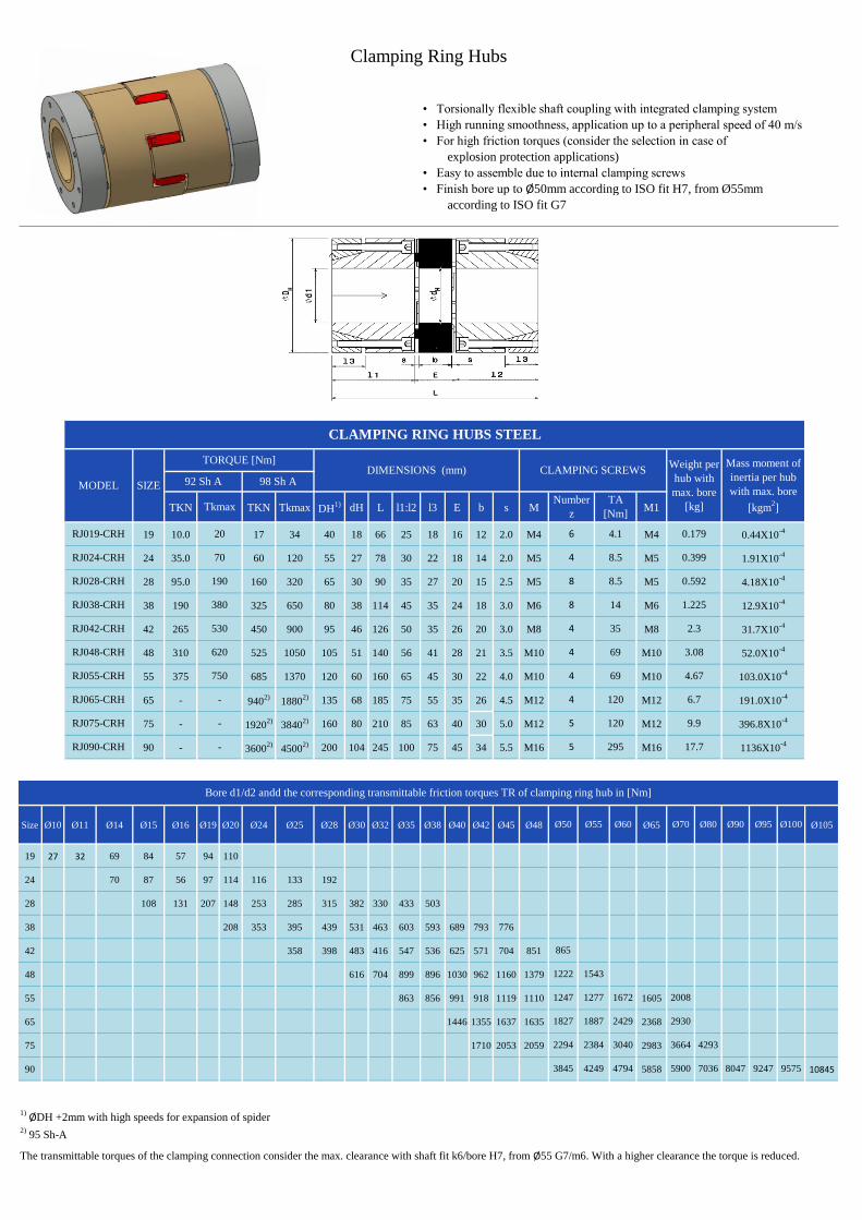
• Torsionally flexible shaft coupling with integrated clamping system
• High running smoothness, application up to a peripheral speed of 40 m/s
• For high friction torques (consider the selection in case of
explosion protection applications)
• Easy to assemble due to internal clamping screws
• Finish bore up to Ø50mm according to ISO fit H7, from Ø55mm
according to ISO fit G7
TKN TKN Tkmax DH1) dH L l1:l2 l3 E b s M M1
19 10.0 17 34 40 18 66 25 18 16 12 2.0 M4 M4
24 35.0 60 120 55 27 78 30 22 18 14 2.0 M5 M5
28 95.0 160 320 65 30 90 35 27 20 15 2.5 M5 M5
38 190 325 650 80 38 114 45 35 24 18 3.0 M6 M6
42 265 450 900 95 46 126 50 35 26 20 3.0 M8 M8
48 310 525 1050 105 51 140 56 41 28 21 3.5 M10 M10
55 375 685 1370 120 60 160 65 45 30 22 4.0 M10 M10
65 - 9402)
18802) 135 68 185 75 55 35 26 4.5 M12 M12
75 - 19202)
38402) 160 80 210 85 63 40 30 5.0 M12 M12
90 - 36002)
45002) 200 104 245 100 75 45 34 5.5 M16 M16
Size Ø10 Ø11 Ø14 Ø15 Ø16 Ø19 Ø20 Ø24 Ø25 Ø28 Ø30 Ø32 Ø35 Ø38 Ø40 Ø42 Ø45 Ø48 Ø65 Ø105
19 27 32 69 84 57 94 110
24 70 87 56 97 114 116 133 192
28 108 131 207 148 253 285 315 382 330 433 503
38 208 353 395 439 531 463 603 593 689 793 776
42 358 398 483 416 547 536 625 571 704 851
48 616 704 899 896 1030 962 1160 1379
55 863 856 991 918 1119 1110 1605
65 1446 1355 1637 1635 2368
75 1710 2053 2059 2983
90 5858 10845
1) ØDH +2mm with high speeds for expansion of spider
2) 95 Sh-A
98 Sh ASIZEMODEL
RJ019-CRH
RJ048-CRH
RJ055-CRH
RJ065-CRH
RJ075-CRH
RJ090-CRH
70
CLAMPING RING HUBS STEEL
RJ024-CRH
RJ028-CRH
RJ038-CRH
RJ042-CRH
Number
z
6
4
8
8
4
Weight per
hub with
max. bore
[kg]
0.179
0.399
0.592
DIMENSIONS (mm) CLAMPING SCREWSTORQUE [Nm]
92 Sh A
190
380 1.225
2.3
20
6.7
Ø50
TA
[Nm]
4.1
8.5
8.5
14
35
69
69
120
120
295
Ø55 Ø60
4
4
4
5
5
9.9
17.7
Ø70 Ø80 Ø95 Ø100
Mass moment of
inertia per hub
with max. bore
[kgm2]
0.44X10⁻⁴
1.91X10⁻⁴
4.18X10⁻⁴
12.9X10⁻⁴
31.7X10⁻⁴
52.0X10⁻⁴
103.0X10⁻⁴
191.0X10⁻⁴
396.8X10⁻⁴
1136X10-4
Ø90
3.08
4.67
-
Clamping Ring Hubs
Bore d1/d2 andd the corresponding transmittable friction torques TR of clamping ring hub in [Nm]
530
620
750
-
-
Tkmax
1277
1543
1827
2294
3845 4249
2384
1887
865
1222
1247 2008
2429
3040
4794 5900
3664
2930
1672
4293
7036 8047
The transmittable torques of the clamping connection consider the max. clearance with shaft fit k6/bore H7, from Ø55 G7/m6. With a higher clearance the torque is reduced.
95759247

• Standard hub material steel
• Suitable in combination with spline bores according to DIN 5480,
DIN 5482, SAE J498 and in addition DIN 9611, DIN 5463 (ISO 14),
DIN 5481 and DIN 5472
• Particularly suitable for applications with reversing operation
Sizes 19-28 Sizes 38-90
max.
dL l1:l2 lmin. E b s DH D dH DK t1 t2 e
19 20 1) 66 25 20 16 12 2.0 40 - 18 46.0 12 - 14.5
24 28 78 30 25 18 14 2.0 55 - 27 57.5 12 - 20.0
28 38 90 35 30 20 15 2.5 65 - 30 73.0 142) - 25.0
38 42 114 45 35 24 18 3.0 80 70 38 77.5 19 - 26.5
42 50 126 50 42 26 20 3.0 95 85 46 93.5 182) - 32.0
48 55 140 56 46 28 21 3.5 105 95 51 105 212) - 36.0
55 68 160 65 50 30 22 4.0 120 110 60 120 26 512) 42.5
3)
65 70 185 75 55 35 26 4.5 135 115 68 133 33 612) 50.0
3)
75 80 210 85 65 40 30 5.0 160 135 80 158 36 682) 57.0
3)
90 90 245 100 80 45 34 5.5 200 160 100 197 40 802) 72.0
3)
Size Ø8 Ø10 Ø11 Ø14 Ø15 Ø16 Ø18 Ø19 Ø20 Ø22 Ø24 Ø25 Ø28 Ø30 Ø32 Ø35 Ø38 Ø40 Ø42 Ø45 Ø48 Ø50 Ø55 Ø60 Ø65 Ø70 Ø75 Ø80 Ø85 Ø90
19 44 46 47 51 52 53 55 57 58
24 59 60 64 65 66 68 70 71 73 76 77 80
28 139 141 144 148 150 152 157 161 163 170 174 178 185 191
38 163 165 170 172 174 178 183 185 192 196 200 207 213 217 222
42 291 297 304 308 318 325 332 342 353 360 367 377 387 394
48 466 476 486 491 506 516 526 542 557 567 577 592 607 618 643
55 1185 1215 1245 1266 1286 1316 1347 1367 1417 1468 1519
65 1316 1347 1367 1387 1417 1448 1468 1519 1569 1620 1671
75 2869 2926 2983 3022 3117 3213 3309 3404 3500 3595
90 5220 5310 5400 5460 5610 5760 5910 6060 6210 6360 6510 6660
DIMENSIONS (mm)
SIZE
RJ075-CH
RJ090-CH
M8
M10
M12
M12
580
CLAMPING HUBS
RJ019-CH
RJ024-CH
RJ028-CH
M
M6
SCREW DIN EN ISO 4762
M6
M8
MODEL
RJ038-CH
RJ042-CH
RJ048-CH
RJ055-CH
RJ065-CH
69
120
120
120
295
Clamping Hubs
Bore area and the corresponding transmittable friction torques [Nm] of clamping hubs
Design 2.0 clamping
hub, single slot, without
keyway
Design 2.1
clamping hub,
single slot, with
keyway
1) With design 2.1 dmax. Ø17mm
2) With reduced hubs the dimension t1 varies or the number of screws changes from 2-off to 1-off
3) t1 and t2 have a different installation dimension e
Design 2.3
clamping hub with
spline bore
M12
M16
M20
TA[Nm]
14
14
35
35

• Double flange design AFN and flange design BFN applicable to heavy machinery
• Radial assembly of driving or driven machine after disassembly of driving flanges
• For design AFN-spider to be replaced while coupling installed, without removal of
driving or driven machine
• Power flow can be disconnected while coupling is installed
• Flange materials: component 4N (C-flange) made of steel, component 3Na
(driving flange) made of GJS
• Finish bore according to ISO fit H7, feather keyway according to DIN 6885 sheet 1-JS9
Pilot Bore
Ød
Max. Bore
Ød1D/D1 DH DF D4 dH l1:l2 E E1 s b l3:l4 LAFN LBFN Mxl z Pitch TA [Nm]
1 40
1a 55
1 48
1a 65
1 66
1a 78
1 75
1a 94
1 85
1a 104
1 98
1a 118
RJ065-AFN/BFN 65 1 22 65 115 135 94 116 68 75 35 65 4.5 26 76.0 217 201 M10x30 12 16x22.5° 83
RJ075-AFN/BFN 75 1 30 75 135 160 18 136 80 85 40 75 5.0 30 86.5 248 229 M12x40 15 120
RJ090-AFN/BFN 90 1 40 100 160 200 142 172 100 100 45 82 5.5 34 101.5 285 265 M16x40 15 295
RJ100-AFN/BFN 100 1 50 110 180 225 158 195 113 110 50 97 6.0 38 111.5 320 295 M16x50 15 295
RJ110-AFN/BFN 110 1 60 125 200 255 178 218 127 120 55 103 6.5 42 122.0 347 321 M20x50 15 20x18° 580
RJ125-AFN/BFN 125 1 60 145 230 290 206 252 147 140 60 116 7.0 46 142.0 400 370 M20x60 15 580
RJ140-AFN/BFN 140 1 60 165 255 320 235 282 165 155 65 128 7.5 50 157.5 443 409 M20x60 15 580
RJ160-AFN/BFN 160 1 80 190 290 370 270 325 190 175 75 146 9.0 57 177.5 501 463 M24x70 15 1000
RJ180-AFN/BFN 180 1 85 220 325 420 315 375 220 195 85 159 10.5 64 198.0 555 515 M24x80 18 24x15° 1000
1) Screw tightening torque TA [Nm]
2) Thread in driving flange between cams
3) Coupling is delivered not assembled
DIMENSIONS (mm)COMPONENT
FOR BFN MODEL
AFN AND BFN
MODEL
SCREWS DIN EN ISO 4762-12.9
SIZE
Flange Programme Design AFN and BFN
TYPE BFNTYPE AFN
RJ055-AFN/BFN 20 55 120 80 60102 65 30 60 4.0 66.022 192 176 M10x30 8 8x45 83
RJ048-AFN/BFN 15 48 105 70 90 51 56 28 50 3.5 21 57.0 164 152 M8x25 12
16x22.5
41
RJ042-AFN/BFN 14 42 95 65 80 46 50 26 48 3.0 20 51.0 150 138 M8x25 12 41
RJ038-AFN/BFN 12 38 80 52 66 38 45 24 43 3.0 18 45.5 134 124 M8x22 8 41
8x45RJ028-AFN/BFN 10 28 65 42 54 30 35 20 39 2.5 15 35.5 110 100 M6x20 8 17
RJ024-AFN/BFN 9 24 55 36 45 27 30 18 33 2.0 14 30.5 94 86 M5x16 8 1024
28
38
42
48
55

• Assembly/disassembly by means of 4 screws only
• Replacement of spider with no need to shift the driving and
driven side (motor and pump)
• Positive-locking and frictionally engaged hub combinations to be
assembled radially (dimension E1 of type AFN=dimension E1 of type A-H)
• Finish bore according to ISO tolerance H7, feather key according
to DIN 6885 sheet 1-JS9
L l1:l2 E b s DH D DK1 DK2 x1/x2 E1 MxlTIGHTENING TORQUE TA
[Nm]
RJ019-A-H 19 20 66 25 16 12 2.0 40 - 46 - 17.5 31 M6x16 14
RJ024-A-H 24 28 78 30 18 14 2.0 55 - 57.5 - 22.5 33 M6x20 14
RJ028-A-H 28 38 90 35 20 15 2.5 65 - 73 - 25.5 39 M8x25 35
RJ038-A-H 38 42 114 45 24 18 3.0 80 - 83.5 - 35.5 43 M8x30 35
50 85 - 93.5 M10x30
55 - 97 - M10x35
55 95 - 105 M12x35
60 - 108.5 - M12x40
68 110 - 119.5 M12x40
70 - 122 - M12x45
70 115 - 123.5 M12x40
80 - 132.5 - M12x45
80 135 - 147.5
90 - 158 -
90 160 - 176
110 - 197 -
RJ100-A-H1) 100 110 270 110 50 38 6.0 225 180 - 185.5 84 102 M16x50 295
RJ110-A-H1) 110 120 295 120 55 42 6.5 255 200 - 208 90 115 M20x60 580
RJ125-A-H1) 125 140 340 140 60 46 7.0 290 230 - 242.5 105 130 M24x70 1000
Please note:
Shell clamping hub can be either with feather key or without feather key1)
From size 100: 4 clamping screws for each clamping hub
Drop-out Center Design Coupling Type A-H
With maximum bore the feather keys are offset to each other by approximately 5°
Hub materials: up to size 90 steel
from size 100 GJS
SIZE
TYPE A-H
MODEL
SCREW DIN EN ISO 4762DIMENSIONS (mm)Max. finish
bore Ød
[mm]
RJ090-A-H 245 100 45 34 5.5 200 81.5 82 M20x60 580
RJ075-A-H 210 85 40 30 5.0 160 67.5 75 M16x50 295
RJ065-A-H 185 75 35 26 4.5 135 60 65 120
RJ055-A-H 160 65 30 22 4.0 120 50 60 120
RJ048-A-H 140 56 28 21 3.5 105 45 50 120
RJ042-A-H 126 50 26 20 3.0 95 39 48 6942
48
55
65
75
90

• Type S-H with split hubs
• Easy assembly/disassembly by means of 4-off screws
• Centering of both halves of the hubs through the fracture surface
• There is no need to displace the power packss for assembly
• Material cast iron
• Torsionally flexible and maintenance-free
• Specifically suitable for tight mounting spaces
• Finish bore according to ISO fit H7, feather
keyway according to DIN 6885 sheet 1-JS9
MIN. MAX. L l1:l2 E b s DH D1 DK N e t1 t2 G Mxl
TIGHTENING
TORQUE TA
[Nm]
RJ038-S-H 38 24 45 114 45 24 18 3 80 78 83.5 37 3 22.5 15 M8x30 34
RJ042-S-H 42 24 55 126 50 26 20 3 95 94 97 40 3 25 M8 M10x30 67
RJ048-S-H 48 24 55 140 56 28 21 3.5 105 104 109 45 3.5 28 M12x35 115
RJ055-S-H 55 24 65 160 65 30 22 4 120 118 122 52 4 32.5 20 M12x40 115
24 70 115 124 45
70 80 135 133 50 M10
40 80 135 147 51
80 90 160 158 57
40 90 160 176 60
90 110 200 197 72
Split hub can be either with feather key or without feather key
SIZE
Drop-out Center Design Coupling Type S-H with SPLIT-hubs
Finish bore Ød
[mm]
TYPE S-H
MODEL
DIMENSIONS (mm) SCREW DIN EN ISO 4762
RJ065-S-H
RJ075-S-H
RJ090-S-H
65
75
90
185 75 35 26 4.5 135 61 37.5 115
290
560
M12x40
M20x60M12305081
210 85 30 5 160 69 42.540 25 M16x50
245 100 45 34 5.5 200