tactical cloud-based mission services in a military ... in a military environment ......
TRANSCRIPT
White Paper
1
Tactical Cloud-Based Mission Services in a Military Environment Juniper Offers a Host of Products that Enable a Secure Transition to the Tactical Cloud
2
White PaperTactical Cloud-Based Mission Services in a Military Environment
©2015, Juniper Networks, Inc.
Table of ContentsIntroduction ........................................................................................................................................................................................................................ 3
Evolution of the Tactical Cloud .................................................................................................................................................................................. 5
NetOps Transformation for the Tactical Cloud .............................................................................................................................................9
Network Virtualization, Software-Defined Networking, and the Tactical Cloud ........................................................................... 10
How Juniper Supports Transformation to the Tactical Cloud .......................................................................................................................11
Simplifying NetOps and Improving Performance ........................................................................................................................................11
Providing a Common Foundation to Automate NetOps Management .............................................................................................12
Creating an Agile Infrastructure .........................................................................................................................................................................14
Secure Gateway Router for Inter-Unit Connectivity ................................................................................................................................. 20
Secure Network Access ...................................................................................................................................................................................... 20
Wireless Access .......................................................................................................................................................................................................22
Optimizations for Networking on the Move (NOTM).......................................................................................................................................22
SDN and SON ..........................................................................................................................................................................................................22
Commercial Off-the-Shelf (COTS)-Based Multisite VPN .....................................................................................................................23
SDN and Cloudlet Cyber Foraging ...................................................................................................................................................................24
Conclusion ........................................................................................................................................................................................................................25
About Juniper Networks ..............................................................................................................................................................................................26
List of FiguresFigure 1: Tactical cloud environment overview ..................................................................................................................................................... 5
Figure 2: Elements of the tactical cloud .................................................................................................................................................................6
Figure 3: Tiers of the ITNE .............................................................................................................................................................................................7
Figure 4: UAS connections for the tactical cloud Networking on the Move (NOTM) ...........................................................................8
Figure 5: QFabric System flattens and simplifies the TOC architecture ...................................................................................................12
Figure 6: Junos Space and Security Director ........................................................................................................................................................13
Figure 7: Junos Space Virtual Director architecture ...........................................................................................................................................13
Figure 8: Role of Contrail in the tactical cloud ....................................................................................................................................................14
Figure 9: Contrail vRouter ............................................................................................................................................................................................15
Figure 10: vRouter forwarding plane ....................................................................................................................................................................... 16
Figure 11: Juniper NFV security services ................................................................................................................................................................. 18
Figure 12: Firefly Host virtualized functions .......................................................................................................................................................... 18
Figure 13: Firefly Perimeter virtual functions ........................................................................................................................................................ 19
Figure 14: Transformed TOC leveraging SDN and NFV capabilities ........................................................................................................... 19
Figure 15: Role of MAP server .....................................................................................................................................................................................21
Figure 16: Integration of SDN with SON ................................................................................................................................................................23
Figure 17: COTS-based Multi-site VPN ..................................................................................................................................................................24
Figure 18: Cloudlet concept .......................................................................................................................................................................................25

3
White PaperTactical Cloud-Based Mission Services in a Military Environment
©2015, Juniper Networks, Inc.
The military’s tactical environment is evolving quickly due to technology advances designed to adapt tactics to
match adversary capabilities. There is also the need to address contested, non-permissive environments; to increase
operational efficiencies; to improve the commander’s decision quality; and to enhance situational awareness. These
changes are having a profound impact on the architecture of the tactical network resulting in the need for a highly agile
infrastructure; resilient, persistent, and high bandwidth communications; and secure connectivity.
The tactical cloud has started to emerge as a key concept for delivering agile and resilient information services to
tactical forces. A tactical cloud-like environment offers needed technology enhancements, and its capabilities enable
the fluid sense-and-respond services that are essential at the tactical edge.
This paper lays out the evolution of tactical cloud-based mission services accessible on the move. It identifies some of
the key drivers for pursuing tactical cloud capabilities and provides descriptions of networking requirements needed to
support this evolution. The paper concludes by illustrating how Juniper technologies can be applied to support a tactical
cloud “on the move.”
IntroductionThe following real-world vignettes help to demonstrate how aspects of a tactical cloud can deliver the capabilities that
a tactical environment requires to meet quickly-evolving needs:
• The Commanding Officer of the USS Wasp just received a new mission package that changes the configurations
and security profile of his shipboard tactical network, while also requiring the provisioning of new application
updates. Despite efficiencies provided by Consolidated Afloat Network and Enterprise Services (CANES) and
Automated Defense Network System (ADNS), he is worried that required changes will necessitate hours if not
days to implement in his network, and to synchronize the changes with the tactical networks of the air wing and
amphibious units deployed onboard, as well as with other ships in the amphibious task force. The combat systems
information officer informs him that recent updates to CANES and ADNS included software-defined networking
(SDN), which can integrate the application updates in the virtualized CANES infrastructure with the network and
easily synchronize the changes in the mission package.
• A Marine squad leader has just finished interrogating a local native in a village where an IED production facility was
recently discovered. The villager’s fingerprints and facial biometrics were captured by applications on the squad
leader’s smartphone. Although he is disconnected from the Tactical Operations Center (TOC) where the central
biometrics database is located, he is able to connect to his LAV-25 that hosts a “cloudlet” able to process the
biometrics he has collected for a rapid check.
• The Combat Systems Information Officer of the USS Lincoln needs to replace a rack of CANES servers that host
virtualized workloads without experiencing any downtime. The virtualized servers support a variety of tenants’
applications. She decides to migrate the workloads to different underutilized servers through virtual machine
(VM) migration. She also leverages Layer 2 over Layer 3 (L2oL3) overlay technologies provided through SDN and
virtualized network functions to rapidly migrate the network connectivity and security protections (e.g., virtual
firewall) at the same time. L2oL3 capability allows her to utilize the proven scalability of L3 addressing and
multipathing technologies of the underlying physical layer, while also creating separate virtual L2 networks that can
then be assigned to each tenant. She also knows that the security of the multitenant virtual workloads is assured
through the virtual gateway that is integrated with each hypervisor in the CANES infrastructure. The virtual gateway
security policy is synchronized with firewalls that control north-south traffic, and it ensures that inter-VM traffic is
controlled appropriately.
• A critical video is being multicast by the USS Lincoln to members of the Carrier Task Force. As the number of users
that access the video increases, the SDN controller senses resource capacity issues on the video server nodes and
bandwidth bottlenecks on the routers. The SDN controller directs the VM orchestrator to provision a new cluster of
video server VMs. Also, a new virtual firewall and virtual gateway are provisioned as part of the overall service chain
to the virtual video server nodes. SDN-aware routers and gateway switches are also updated via direction provided
by the SDN controller for quality-of-service (QoS) changes related to the new traffic flows.
As these example vignettes indicate, the tactical edge is characterized as a highly dynamic environment with forces
on the move, unpredictable changes in operational tempo and fluctuations in network connectivity, bursty information
flows, and frequent modifications to mission plans and force elements. These variations necessitate a high degree of
resiliency and agility in operations, while placing significant operational and technical constraints on the underlying
computing and networking infrastructure of the tactical edge.
4
White PaperTactical Cloud-Based Mission Services in a Military Environment
©2015, Juniper Networks, Inc.
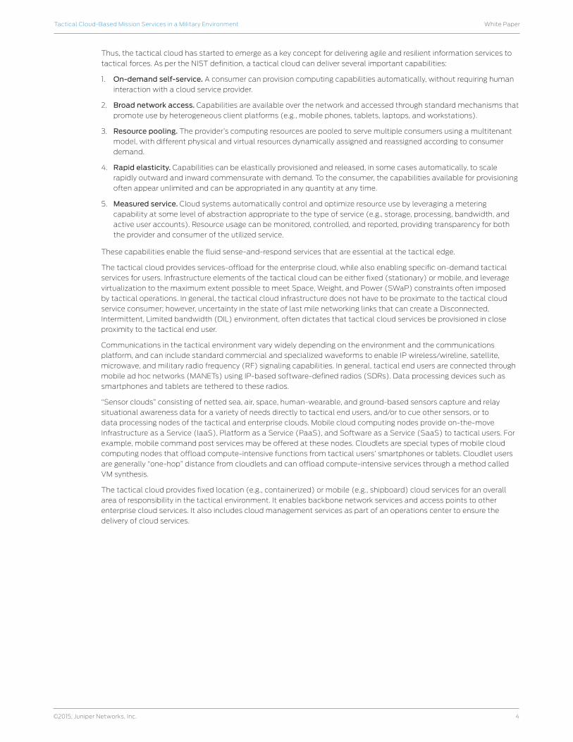
Thus, the tactical cloud has started to emerge as a key concept for delivering agile and resilient information services to
tactical forces. As per the NIST definition, a tactical cloud can deliver several important capabilities:
1. On-demand self-service. A consumer can provision computing capabilities automatically, without requiring human
interaction with a cloud service provider.
2. Broad network access. Capabilities are available over the network and accessed through standard mechanisms that
promote use by heterogeneous client platforms (e.g., mobile phones, tablets, laptops, and workstations).
3. Resource pooling. The provider’s computing resources are pooled to serve multiple consumers using a multitenant
model, with different physical and virtual resources dynamically assigned and reassigned according to consumer
demand.
4. Rapid elasticity. Capabilities can be elastically provisioned and released, in some cases automatically, to scale
rapidly outward and inward commensurate with demand. To the consumer, the capabilities available for provisioning
often appear unlimited and can be appropriated in any quantity at any time.
5. Measured service. Cloud systems automatically control and optimize resource use by leveraging a metering
capability at some level of abstraction appropriate to the type of service (e.g., storage, processing, bandwidth, and
active user accounts). Resource usage can be monitored, controlled, and reported, providing transparency for both
the provider and consumer of the utilized service.
These capabilities enable the fluid sense-and-respond services that are essential at the tactical edge.
The tactical cloud provides services-offload for the enterprise cloud, while also enabling specific on-demand tactical
services for users. Infrastructure elements of the tactical cloud can be either fixed (stationary) or mobile, and leverage
virtualization to the maximum extent possible to meet Space, Weight, and Power (SWaP) constraints often imposed
by tactical operations. In general, the tactical cloud infrastructure does not have to be proximate to the tactical cloud
service consumer; however, uncertainty in the state of last mile networking links that can create a Disconnected,
Intermittent, Limited bandwidth (DIL) environment, often dictates that tactical cloud services be provisioned in close
proximity to the tactical end user.
Communications in the tactical environment vary widely depending on the environment and the communications
platform, and can include standard commercial and specialized waveforms to enable IP wireless/wireline, satellite,
microwave, and military radio frequency (RF) signaling capabilities. In general, tactical end users are connected through
mobile ad hoc networks (MANETs) using IP-based software-defined radios (SDRs). Data processing devices such as
smartphones and tablets are tethered to these radios.
“Sensor clouds” consisting of netted sea, air, space, human-wearable, and ground-based sensors capture and relay
situational awareness data for a variety of needs directly to tactical end users, and/or to cue other sensors, or to
data processing nodes of the tactical and enterprise clouds. Mobile cloud computing nodes provide on-the-move
Infrastructure as a Service (IaaS), Platform as a Service (PaaS), and Software as a Service (SaaS) to tactical users. For
example, mobile command post services may be offered at these nodes. Cloudlets are special types of mobile cloud
computing nodes that offload compute-intensive functions from tactical users’ smartphones or tablets. Cloudlet users
are generally “one-hop” distance from cloudlets and can offload compute-intensive services through a method called
VM synthesis.
The tactical cloud provides fixed location (e.g., containerized) or mobile (e.g., shipboard) cloud services for an overall
area of responsibility in the tactical environment. It enables backbone network services and access points to other
enterprise cloud services. It also includes cloud management services as part of an operations center to ensure the
delivery of cloud services.
5
White PaperTactical Cloud-Based Mission Services in a Military Environment
©2015, Juniper Networks, Inc.
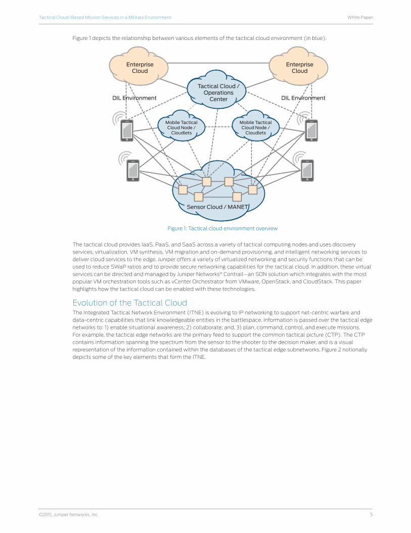
Figure 1 depicts the relationship between various elements of the tactical cloud environment (in blue).
Figure 1: Tactical cloud environment overview
The tactical cloud provides IaaS, PaaS, and SaaS across a variety of tactical computing nodes and uses discovery
services, virtualization, VM synthesis, VM migration and on-demand provisioning, and intelligent networking services to
deliver cloud services to the edge. Juniper offers a variety of virtualized networking and security functions that can be
used to reduce SWaP ratios and to provide secure networking capabilities for the tactical cloud. In addition, these virtual
services can be directed and managed by Juniper Networks® Contrail—an SDN solution which integrates with the most
popular VM orchestration tools such as vCenter Orchestrator from VMware, OpenStack, and CloudStack. This paper
highlights how the tactical cloud can be enabled with these technologies.
Evolution of the Tactical CloudThe Integrated Tactical Network Environment (ITNE) is evolving to IP networking to support net-centric warfare and
data-centric capabilities that link knowledgeable entities in the battlespace. Information is passed over the tactical edge
networks to: 1) enable situational awareness; 2) collaborate; and, 3) plan, command, control, and execute missions.
For example, the tactical edge networks are the primary feed to support the common tactical picture (CTP). The CTP
contains information spanning the spectrum from the sensor to the shooter to the decision maker, and is a visual
representation of the information contained within the databases of the tactical edge subnetworks. Figure 2 notionally
depicts some of the key elements that form the ITNE.
Sensor Cloud / MANET
Tactical Cloud /Operations
Center
EnterpriseCloud
EnterpriseCloud
Mobile TacticalCloud Node /
Cloudlets
Mobile TacticalCloud Node /
Cloudlets
DIL EnvironmentDIL Environment

6
White PaperTactical Cloud-Based Mission Services in a Military Environment
©2015, Juniper Networks, Inc.
Figure 2: Elements of the tactical cloud
The ITNE is designed to provide three levels of network services within the battlespace. One service level (combat
tier) supports a mobile ad hoc wireless networking capability to enable just-in-time connectivity among highly
mobile ground users, netted sensors, and sea- or air-based mobile platforms. The second service level (core tier)
supports a high bandwidth backbone service to interconnect larger Command and Control, Intelligence, Surveillance,
and Reconnaissance (C2ISR) nodes in the battlespace. The backbone enables reuse of available non-Satellite
Communications (SATCOM) bandwidth. The third service level (reachback tier) supports beyond line of sight
communications into Global Information Grid (GIG) points of presence.
Cellular Networks
In-VehicleComputers
Remote Sensingand Control
Embedded WiFi Technology
Perimeter Securityand Tracking
Mobile Apps Store
Video Streamingand Analytics
Tactical CloudServices
Command Center/Tactical Operations

7
White PaperTactical Cloud-Based Mission Services in a Military Environment
©2015, Juniper Networks, Inc.
Figure 3: Tiers of the ITNE
One of the key challenges affecting the evolution of the ITNE to a tactical cloud environment is that the advanced
communications capabilities that underpin tactical operations might not be available in a conflict (e.g., SATCOM or
broadband connectivity to backbone). Instead, an adversary could induce a DIL scenario, which could affect all tiers,
although the combat tier is most affected by DIL situations. At the combat tier, small groups of platforms or individual
users are interconnected for relatively short periods of time (hours) under conditions where the mobility of the platforms
and users has the potential for extremely frequent changes in link connectivity. These MANETs are generally constrained
with respect to onboard resources and environmental conditions, so the only networking services performed in this
tier are those that are absolutely essential. The resource limited constraints in these combat tier networks require that
respective nodes retain limited global knowledge of the battlespace, opportunistically communicate with other nodes,
and make efficient use of the scarce available bandwidth.
A DIL scenario may negatively affect the operation of cloud services delivered to the battlespace. Generally, cloud
services are offered in situations where bandwidth is not a limiting factor on their delivery. However, the design of a
tactical cloud must be tailored to support bandwidth-constrained, space/weight-constrained, and power-constrained
environments, while being able to scale up, scale out, and scale down quickly.
MANET technologies are likely to progress over the next several years from advanced RF networks utilizing Soldier
Radio Waveform (SRW) and Wideband Networking Waveform (WNW), to also include mobile IP-based networks,
Network Mobility (NEMO), LTE 4G, Cloud RAN, RAN 2.0, variants of these and other network technologies currently
under development. Also, aerial platforms such as Unmanned Aerial Systems (UAS) are already being introduced into
the networked MANET environments to enable higher bandwidth services including C2ISR ((such as full motion video
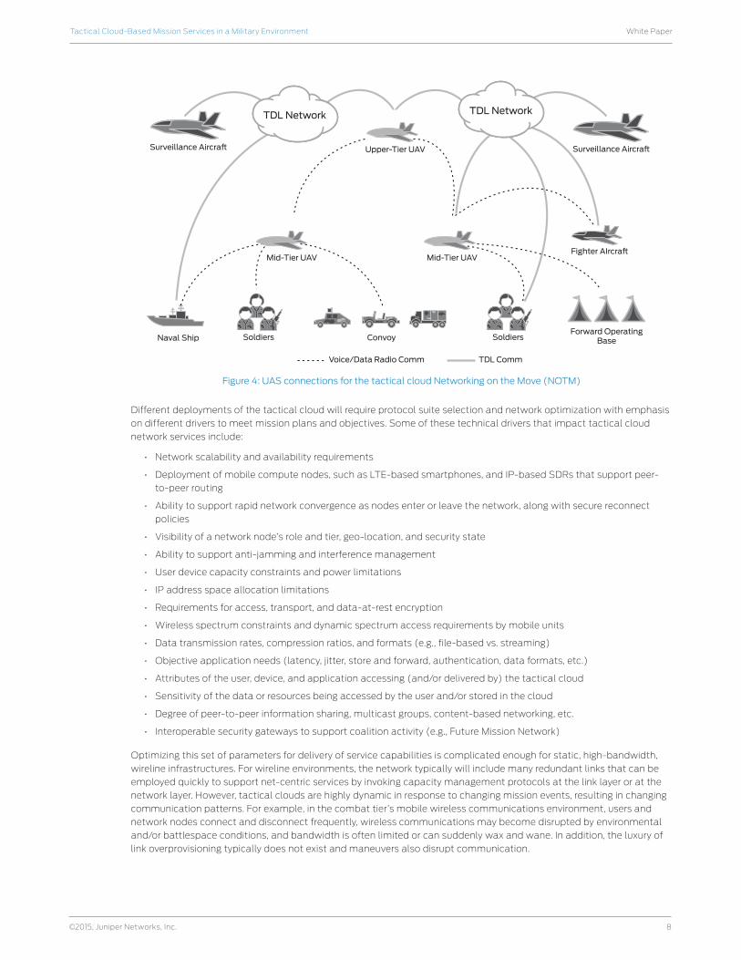
(FMV)), reachback to the GIG, inter-unit communications, and backbone connectivity. Figure 4 illustrates this wide range
of UAS connectivity of the combat tier.
Post/Camp/Station
Global DefenseNetwork
Core Tier
UAS
ReachbackTier
At Home/TDY
Combat Tier
Internet
Teleport/STEP
SatelliteTransport
Combat Tier
8
White PaperTactical Cloud-Based Mission Services in a Military Environment
©2015, Juniper Networks, Inc.
Figure 4: UAS connections for the tactical cloud Networking on the Move (NOTM)
Different deployments of the tactical cloud will require protocol suite selection and network optimization with emphasis
on different drivers to meet mission plans and objectives. Some of these technical drivers that impact tactical cloud
network services include:
• Network scalability and availability requirements
• Deployment of mobile compute nodes, such as LTE-based smartphones, and IP-based SDRs that support peer-
to-peer routing
• Ability to support rapid network convergence as nodes enter or leave the network, along with secure reconnect
policies
• Visibility of a network node’s role and tier, geo-location, and security state
• Ability to support anti-jamming and interference management
• User device capacity constraints and power limitations
• IP address space allocation limitations
• Requirements for access, transport, and data-at-rest encryption
• Wireless spectrum constraints and dynamic spectrum access requirements by mobile units
• Data transmission rates, compression ratios, and formats (e.g., file-based vs. streaming)
• Objective application needs (latency, jitter, store and forward, authentication, data formats, etc.)
• Attributes of the user, device, and application accessing (and/or delivered by) the tactical cloud
• Sensitivity of the data or resources being accessed by the user and/or stored in the cloud
• Degree of peer-to-peer information sharing, multicast groups, content-based networking, etc.
• Interoperable security gateways to support coalition activity (e.g., Future Mission Network)
Optimizing this set of parameters for delivery of service capabilities is complicated enough for static, high-bandwidth,
wireline infrastructures. For wireline environments, the network typically will include many redundant links that can be
employed quickly to support net-centric services by invoking capacity management protocols at the link layer or at the
network layer. However, tactical clouds are highly dynamic in response to changing mission events, resulting in changing
communication patterns. For example, in the combat tier’s mobile wireless communications environment, users and
network nodes connect and disconnect frequently, wireless communications may become disrupted by environmental
and/or battlespace conditions, and bandwidth is often limited or can suddenly wax and wane. In addition, the luxury of
link overprovisioning typically does not exist and maneuvers also disrupt communication.
Forward OperatingBaseSoldiersConvoyNaval Ship Soldiers
Mid-Tier UAVFighter AIrcra�
Upper-Tier UAV
Voice/Data Radio Comm
Mid-Tier UAV
Surveillance Aircra�Surveillance Aircra�
TDL NetworkTDL Network
TDL Comm

9
White PaperTactical Cloud-Based Mission Services in a Military Environment
©2015, Juniper Networks, Inc.
The fluid environment of the tactical cloud necessitates visibility and control of networked resources at a logical level,
and topology simplification and convergence of resources at the physical layer. Therefore, tactical communications
can benefit by employing virtual network services that are delivered using cross-layer network design and cross-layer
optimization protocols. Cross-layer approaches ensure the discoverability of attributes across different layers of the
communication stack; help to isolate or connect virtual network services; and provide feedback on concurrent quality
information for the responsive setting of control parameters. In addition, a tactical cloud must be adaptive to any
underlying (physical) network infrastructure. It must support applications and services implemented with all identifiable
permutations of current technology and work with any vendor.
NetOps Transformation for the Tactical CloudThe Tactical Operations Center is a hub for tactical cloud management services. Various cloud mission services, and
network and security management activities for the battlespace will reside here. The TOC provides fixed backbone
networking between the different MANETs of the combat tier, gateways for legacy networks, and reachback services to a
military service entry point.
TOC network planners and administrators currently face many complexities in establishing an ITNE for the battlespace.
A myriad of platforms, applications, routing schemes, network associations, spectrum allocations, and information
elements must be evaluated against the mission plan, as well as configured and implemented as part of a complex
network operations plan. Planning is hampered by stovepiped processes that drive the need for a large number of tools
to manage the network. Current network components are initialized in different ways using different tools. The lack of
common federated NetOps interfaces also inhibits dynamic operations (e.g., combat loss leading to unit reorganization).
As a result, the effort required to adequately plan, configure, and implement the unique requirements of the network per
mission plan can be enormously time-consuming as well as costly to develop and maintain the necessary skills.
TOC operators also have many challenges keeping the network running and doing their jobs efficiently. Everyday tasks
such as monitoring devices, troubleshooting, maintaining security, and software upgrades are increasingly difficult as
the number of independent devices in the network increase. Such fault, configuration, accounting, performance, and
security (FCAPS) operational challenges are further compounded if these devices are running different versions of
software or have different configurations, since software must be carefully managed across devices to ensure consistent
functionality and to limit exposure to bugs or handle other Information Assurance Vulnerability Alerts (IAVAs). Special
training or expertise may also be needed to support these configurations. In addition, equipment is moving out of the
TOC and into lower echelons of the C2 hierarchy; however, the personnel who staff that equipment are not always
moving down to those lower echelons.
Besides these planning and operational challenges, the complexities created by the multitiered networks of today’s
TOCs also lead to increased latency, delays in network convergence, and limited bandwidth availability:
• Latency caused by the network architecture: Approximately 75% of all traffic in today’s modern data center
is server-to-server, which means it travels laterally, or east to west, across the infrastructure. However, due to
the multilayered architecture employed by the TOC networks, this traffic must first travel north and south from
the access layer up to the aggregation and core layers and then back down again before it reaches its final
destination—a costly, inefficient use of network assets that adds latency and complexity to each transaction.
• Suboptimal use of access and uplink ports: In today’s data center, approximately 50% of access layer switch
ports are used for inter-switch connections to higher layer devices in the hierarchical tree, limiting the bandwidth
available for supporting customer connections.
• Layer 2 control plane scaling: Spanning Tree Protocol (STP) is typically employed to prevent network loops from
occurring in the data center. However, STP can take up to 50 seconds to converge in a network following a failure—
even the Rapid Spanning Tree Protocol (RSTP) can require tens of seconds to converge in some topologies.
Plus, both STP and RSTP render half the ports in the core and aggregation layers unusable, leading to inefficient
bandwidth utilization. Virtualized servers compound these problems, since they too require high performance and
low latency.
• Resource consumption: The inability to efficiently scale bandwidth in modern data centers compels operators
to actually add more of the same inefficient devices to meet growing bandwidth demands. These extra devices
consume additional rack space, power, and cooling.
As a result of these operational challenges and suboptimizations, the TOCs of today are undergoing transformations in
their design and operation. The purpose of these transformations is to simplify the administration of tactical operations,
improve SWaP ratios, enable more agile capabilities, improve network performance, and support tactical networking
on the move. To these ends, the TOC networks are being flattened. New higher bandwidth connections are being
deployed. TOC capabilities are becoming virtualized. New server and network provisioning and monitoring capabilities
that consolidate multiple management tools and simplify network administration are being added. Greater emphasis
is also being placed on security, as lack of a common security architecture at the tactical edge limits interoperability

10
White PaperTactical Cloud-Based Mission Services in a Military Environment
©2015, Juniper Networks, Inc.
and increases the cost of fielding C2 systems. Identity and Access Management (IDAM) initiatives are underway to
drive anonymity out of the network. 4G LTE and Wi-Fi are also being considered as key enablers for tactical networks to
reduce network cabling requirements, complement existing radio waveforms, and to support the deployment of secure
handhelds into the wireless tactical environment.
In addition to transformation of the TOC, battlefield communications are also undergoing transition as unmanned
aerial systems (UAS) and satellites (e.g., MUOS) offer new on-demand and always-on communications services.
These services are designed to provide persistent sensor-to-shooter connectivity through high-capacity IP-based
communications platforms that support interoperation across different radio waveforms and relay or gateway functions
between dispersed units. This set of aerial communications capabilities is embodied in the Joint Aerial Layer Network
(JALN), which consists of a variety of aerial platforms that serve as nodes in a larger network. The aerial nodes help
extend the range of ground-based tactical radios and allow for interoperable radio communications between troops on
the ground and the aircraft supporting them.
An aerial integration router is needed for JALN mission-persistent inter-unit communications. With a gateway or
integration router on an unmanned aerial vehicle (UAV), disparate radio networks can be automatically linked together
on the UAV instead of at a terrestrial TOC, which may have limitations as mobile units maneuver away from the TOC.
The aerial and ground-based nodes must automatically enable a “self-organizing network” or SON to connect dispersed
units and to ensure uninterrupted network connectivity for mobile users. For example, consider the case of a vehicular
node running SRW and Adaptive Networking Wideband Waveform (ANW2) on its two-channel radio that moves
away from the footprint of the UAV on the SRW channel. The gateway router on a nearby UAV automatically detects
this and switches to the ANW2 channel to provide connectivity through an airborne node such as Battlefield Airborne
Communication Node (BACN).
Network Virtualization, Software-Defined Networking, and the Tactical CloudThe tactical cloud is composed of a variety of different technologies distributed in the battlespace. Network services
must be dynamically assimilated from these varied technologies to meet a range of mission needs. Network Functions
Virtualization (NFV) and SDN help provide the ability to address these changing needs as part the evolution of a tactical
cloud infrastructure.
NFV enables networks to have elastic services that operate as virtual machines. Additionally, NFV allows network
services to scale out horizontally and independently from networking hardware. Key principles supported by NFV include:
• NFV establishes a virtual set of network services independent of the physical network location or state.
- Enables a logical network across any server, any rack, any cluster, and any data center.
- VMs can migrate without requiring any reworking of security policies, load balancing, etc.
- New workloads or networks should not require (re)-provisioning of the physical network.
- Nodes in the physical network can fail without any disruption to the workload.
• NFV supports full isolation for multitenancy and fault tolerance.
- Media access control (MAC) and IP addresses are completely private per tenant.
- Any failures or configuration errors by tenants do not affect other applications or tenants.
- Any failures in the virtual layer do not propagate to the physical layer.
This separation and virtualization of network services is a key principle and evolutionary step in SDN adoption. In a cloud
environment, it is necessary to provide connectivity between virtualized functions (or VMs), while maintaining separation
between tenants of the tactical cloud environment. Today, one way to achieve this is by the use of constructs such as
VLANs. However, these are rather static and difficult to provision—and that’s where SDN and NFV come together. To
provide fully dynamic and automated provisioning and monitoring for NFV, it is very beneficial to use an SDN controller
and a VM orchestration system.
The goal of SDN is to allow network engineers and administrators to respond quickly to changing mission requirements.
In a software-defined network, a network administrator can shape traffic from a centralized control console
without having to touch individual networking components. To understand the steps required to move toward SDN
implementation, tactical mission organizations need to visualize their networks as having several different planes that
combine to deliver necessary computing capabilities and services. Among these are the:
• Management plane: Provides the network schematic and enables centralized management of network
components, services, and overall performance. SDN requires the separation of configuration management
from the network hardware. Once separated and centralized, intelligence and automation can be added to the
management functions.

11
White PaperTactical Cloud-Based Mission Services in a Military Environment
©2015, Juniper Networks, Inc.
• Services plane: Focuses on the dedicated hardware that delivers specific network functions, such as load
balancing and network access control (NAC). SDN decouples these services from dedicated hardware and delivers
them as software.
• Control plane: Serves as the network choreographer. In SDN environments, the control plane understands the
network schematic thanks to the management plane and is therefore able to configure the network in response
to specified commands. The control plane creates an overlay—a temporary network put in place to address a
demand—without having to touch the underlay, answering requests efficiently without impacting the underlying
network. The control plane also choreographs the services enabling them to be scaled up or down.
• Forwarding plane: Comprises virtual network elements (vRouters) that carry network user data. vRouters are
responsible for forwarding packets from one virtual machine to other virtual machines via a set of server-to-server
tunnels. The tunnels form an overlay network sitting on top of a physical IP-over-Ethernet network.
For the tactical cloud, some of the network elements that constitute these different “planes” should be implemented
centrally at the tactical operations center, while other network elements should remain distributed. In general, the
forwarding and services planes can be distributed, while management and control planes remain logically centralized
where possible. Optimizing the distribution of network elements in this way will enable organizations to reap multiple
benefits, including decreased outages and significant increases in efficiency.
If NFV is present without SDN and orchestration, the resulting services may require manually intensive network topology
preplanning and extensive preprovisioning. This manual approach, widely employed by today’s tactical network
administrators, is inefficient, and it takes too much time as complex network reconfiguration is done per dynamic move/
add/change for each network topology change. In an SDN environment, the administrator is only concerned with the
logical overlay network when having to institute network service changes needed to meet changing mission needs. This
kind of network automation significantly decreases the time and effort required to make periodic network updates.
Another significant cost reduction is related to training. By eliminating the need to understand, operate, and repair
multiple device types and interfaces from a range of vendors, administrators need only be familiar with the centralized
control plane to manage services and network capacity with a single interface.
Ultimately, centralizing the management plane reduces the amount of time tactical IT staff are required to invest in
changing, repairing, and managing the networks they support. The objective is to free up skilled professionals to allow
them to minimize routine tasks and instead focus on performing more mission-essential tasks. The result is that NFV
and SDN are inextricably bound because they both solve different parts of the same problems around horizontal scaling
and service chain creation. A truly dynamic tactical cloud requires both NFV and SDN.
How Juniper Supports Transformation to the Tactical Cloud Juniper provides technology that can assist in meeting the tactical operations transformation objectives in multiple
ways:
1. By providing innovative approaches at the switch layer through the use of Virtual Chassis technology and Juniper
Networks QFabric™ System, Juniper can simplify NetOps while improving network performance and resiliency.
2. By employing a common operational and management platform—Juniper Networks Junos® operating system and
Junos Space— Juniper can automate element management across physical and virtual network components.
3. Through virtualization of network services, combined with the SDN-ready Juniper Networks Contrail and MX Series
3D Universal Edge Routers, Juniper can enable an agile, distributed, cloud infrastructure.
4. By enabling interoperation at a router level between different radio waveforms, and also through modular chassis
or rack-mounted Juniper Networks CTP Series Circuit to Packet Platforms, circuit-based applications can be reliably
connected across IP networks such as for UAV backhaul connections.
5. Through standards-based network access control (NAC) capabilities, Juniper can enable comply-to-connect and
real-time situational awareness functionality for all networked nodes, including wireless mobile devices.
Descriptions of these capabilities are provided below.
Simplifying NetOps and Improving PerformanceJuniper offers a capability known as Virtual Chassis technology, which combines the scalability and compact form factor
of standalone switches with the high availability, high backplane bandwidth characteristics and high port densities of
traditional chassis-based switches. Virtual Chassis configurations enable economical deployments of switches that
deliver network availability in locations where installation might otherwise be cost prohibitive or physically impossible.
In a Virtual Chassis configuration, all member switches are managed and monitored as a single logical device. This
approach simplifies network operations, allows the separation of placement and logical groupings of physical devices,
12
White PaperTactical Cloud-Based Mission Services in a Military Environment
©2015, Juniper Networks, Inc.
and provides efficient use of resources. Virtual Chassis technology also reduces latency by flattening the network. Inter-
switch traffic is routed over a dedicated Virtual Chassis backplane at line rates for all packet sizes, rather than flooding
traffic over access ports, to preserve valuable bandwidth. Also, with Virtual Chassis technology, node and link failover
times are measured in sub-seconds, without the need for an external Layer 2 control plane protocol like STP, creating a
loop-free topology.
Juniper also offers a fabric switching solution known as QFabric System, which delivers any-to-any connectivity and
simplified operations, making it the ideal architectural foundation for TOCs. The QFabric System is a scalable, high-
performance, nonblocking, and easy-to-manage fabric that enables traditional Layer 2 and Layer 3 connectivity along
with virtualization and convergence. The standards-based QFabric System is completely interoperable and seamlessly
integrates with existing environments, allowing them to easily migrate from traditional tiered networks to a single-tier
QFabric architecture.
This architecture connects compute, storage, network, and services resources as extensions of a low-latency network.
By providing direct connectivity and predictable high performance at scale between any two ports in the fabric, common
changes in the data center such as adding capacity, virtual machine mobility, or deploying new applications can be
achieved quickly and easily. The QFabric System’s flat architecture also enables the industry’s first integrated security
solution that provides visibility, enforcement, and scale across the entire physical and virtual data center fabric. QFabric
System offerings are available for container data center environments and support up to 768 10GbE ports with an average
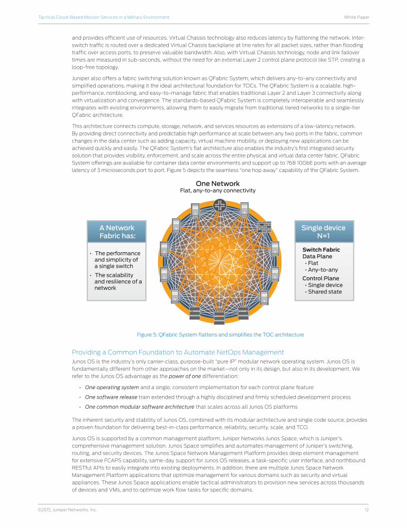
latency of 3 microseconds port to port. Figure 5 depicts the seamless “one hop away” capability of the QFabric System.
Figure 5: QFabric System flattens and simplifies the TOC architecture
Providing a Common Foundation to Automate NetOps ManagementJunos OS is the industry’s only carrier-class, purpose-built “pure IP” modular network operating system. Junos OS is
fundamentally different from other approaches on the market—not only in its design, but also in its development. We
refer to the Junos OS advantage as the power of one differentiation:
• One operating system and a single, consistent implementation for each control plane feature
• One software release train extended through a highly disciplined and firmly scheduled development process
• One common modular software architecture that scales across all Junos OS platforms
The inherent security and stability of Junos OS, combined with its modular architecture and single code source, provides
a proven foundation for delivering best-in-class performance, reliability, security, scale, and TCO.
Junos OS is supported by a common management platform, Juniper Networks Junos Space, which is Juniper’s
comprehensive management solution. Junos Space simplifies and automates management of Juniper’s switching,
routing, and security devices. The Junos Space Network Management Platform provides deep element management
for extensive FCAPS capability, same-day support for Junos OS releases, a task-specific user interface, and northbound
RESTful APIs to easily integrate into existing deployments. In addition, there are multiple Junos Space Network
Management Platform applications that optimize management for various domains such as security and virtual
appliances. These Junos Space applications enable tactical administrators to provision new services across thousands
of devices and VMs, and to optimize work flow tasks for specific domains.
Switch FabricData Plane • Flat • Any-to-any
Control Plane • Single device • Shared state
Single deviceN=1
A Network Fabric has:
One NetworkFlat, any-to-any connectivity
• The performance and simplicity of a single switch
• The scalability and resilience of a network
13
White PaperTactical Cloud-Based Mission Services in a Military Environment
©2015, Juniper Networks, Inc.
For example, Junos Space Security Director is a security management Space application that provides extensive security
scale, policy control, and reach across the network. Security Director eases administration through a responsive Web
interface and granular control over global, group, and device-level firewall policies. Administrators can manage the
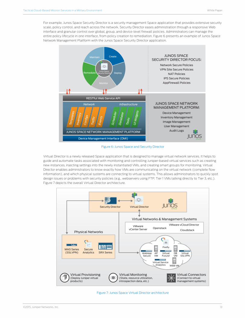
entire policy lifecycle in one interface, from policy creation to remediation. Figure 6 presents an example of Junos Space
Network Management Platform with the Junos Space Security Director application.
Figure 6: Junos Space and Security Director
Virtual Director is a newly released Space application that is designed to manage virtual network services. It helps to
guide and automate tasks associated with monitoring and controlling Juniper-based virtual services such as creating
new instances, injecting settings into the newly instantiated VMs, and creating smart groups for monitoring. Virtual
Director enables administrators to know exactly how VMs are communicating on the virtual network (complete flow
information), and which physical systems are connecting to virtual systems. This allows administrators to quickly spot
design issues or problems with security policies (e.g., webservers using FTP, Tier 1 VMs talking directly to Tier 3, etc.).
Figure 7 depicts the overall Virtual Director architecture.
Figure 7: Junos Space Virtual Director architecture
Junos SpaceSecurity Director Deploy
CreateMaintain
Remediate
Monitor
JUNOS SPACE SECURITY DIRECTOR FOCUS:
Network Secure Policies
VPN Site Secure Policies
NAT Policies
IPS Secure Policies
AppFirewall Policies
JUNOS SPACE NETWORKMANAGEMENT PLATFORM:
Device Management
Inventory Management
Image Management
User Management
Audit Logs
Tem
pla
tes
Inve
nto
ry
Co
nfi
gs
Traf
fic
Sch
edu
ler
Dat
ab
ase
Task
s
UI W
idge
ts
Eve
nts
Network Infrastructure
JUNOS SPACE NETWORK MANAGEMENT PLATFORM
RESTful Web Service API
Device Management Interface (DMI)
MAG Series(SSLVPN)
SecureAnalytics WebApp
Secure
Virtual ServiceAnalytics
Firefly
VirtualFuture!
WEB VM
APVM
DBVM
VirtualSSLVPN
VMwarevCenter Server
Virtual Director
Openstack
Virtual Networks & Management Systems
Physical Networks
Virtual Provisioning(Deploy Juniper virtual products)
Virtual Monitoring(State, resource utilization,introspection data, etc.)
Virtual Connectors(Connect to virtualmanagement systems)
VMware vCloud Director
Cloudstack
SRX Series
Security Director

14
White PaperTactical Cloud-Based Mission Services in a Military Environment
©2015, Juniper Networks, Inc.
Creating an Agile InfrastructureBy creating an abstract service layer of NFV-based services, implemented over an SDN control plane, an administrator
can easily change a network component’s rules when necessary—prioritizing, deprioritizing, or even blocking specific
types of packets with a very granular level of control. Essentially, the abstraction layer helps to define a virtual network
that presents logical network components—logical switches, logical routers, logical firewalls, logical load balancers,
logical VPNs and more—to connected workloads. Logical networks are created, provisioned, and managed through the
SDN controller and VM orchestrators, utilizing the underlying physical network as a simple packet forwarding backplane.
Network and security services are distributed and attached to VMs within a network. As a VM is moved to another host,
these services stay attached to the VM and move with it. In addition, as new VMs are added to a network to scale an
application, policy can be dynamically applied to the new VMs.
For example, using the Contrail Controller, users can dynamically create service chains, which hook NFV functions
together in an automated and seamless fashion. Dynamic service chaining can be applied in many different ways.
Network operators can use these services to replace network functions today hosted on physical appliances, thereby
improving the efficiency of the TOC and the tactical networks. In addition to NFV services, standard computing nodes
can also be attached to the service chains which provide multitenanted services as well.
Contrail exposes the concept of “SDN as a compiler” by translating abstract commands into specific rules/policies to
automate the provisioning of workloads and enable service chaining of network and security services. Users can request
virtual machines without getting into the details of underlying elements like ports, VLANs, subnets, switches, routers,
etc. In addition, a set of unified information models for configuration, operation, and analytics is exposed through
REST APIs, as well as libraries in various programming languages such as Python, JavaScript, and Java, to name a few.
At the forwarding plane level, Contrail has its own vRouter which sits within different hypervisors and provides the
overlay network. These hypervisors could be KVM or Xen. The vRouter performs bridging (EVPN) and routing (L3VPN)
and enables other networking services like security policies, Network Address Translation (NAT), multicast, mirroring,
and load balancing. VM provisioning, VM storage, and monitoring could be provided by an orchestration platform like
OpenStack. Figure 8 shows how Contrail fits into the overall architecture of a tactical cloud environment.
Figure 8: Role of Contrail in the tactical cloud
As shown in Figure 8, the Contrail Controller integrates with open cloud orchestration solutions (i.e., CloudStack and
OpenStack). It is an SDN controller and sits between the orchestration system and network devices (physical underlay,
virtualized appliances), communicating via published RESTful APIs.
IP fabric(underlay network)
BGPFederation
Openstack cloudstack
N/B REST APIs
Horizontally scalableHighly availableFederated
ContrailController
BGP Federation
XMPP
VM
WAN Gateway
VM VM VM VM VM
vRouter vRouter
ConfigurationManagement
Analytics
Control
Agent/Router(KVM, Xen,Linux . . .)
Tunnel fabric – MPLS overGRE/UDP, VXLAN, NVGRE
Virtualized Server
Contrail Controller
Cloud Orchestration
WAN Gateway
Virtualized Server
15
White PaperTactical Cloud-Based Mission Services in a Military Environment
©2015, Juniper Networks, Inc.
Contrail Controller has three software components:
• Configuration: Accepts requests from an orchestrator for provisioning a VM and assigns a network to the same. It
then converts this high-level request into a low-level request that can be understood by network elements.
• Control: Interacts with network elements using Extensible Messaging and Presence Protocol (XMPP), and
directs provisioning of the network for a virtual machine using XMPP. This plane is logically centralized and is also
responsible for maintaining the ephemeral state of a network. It interacts with a peer control plane using industry
standard BGP and ensures network uptime at all times.
• Analytics: Collects, stores, correlates, and analyzes information across network elements. This information
includes statistics, logs, events, and errors; it can be consumed by end-user or network applications through
Contrail’s northbound REST API; and it can be analyzed with SQL style queries.
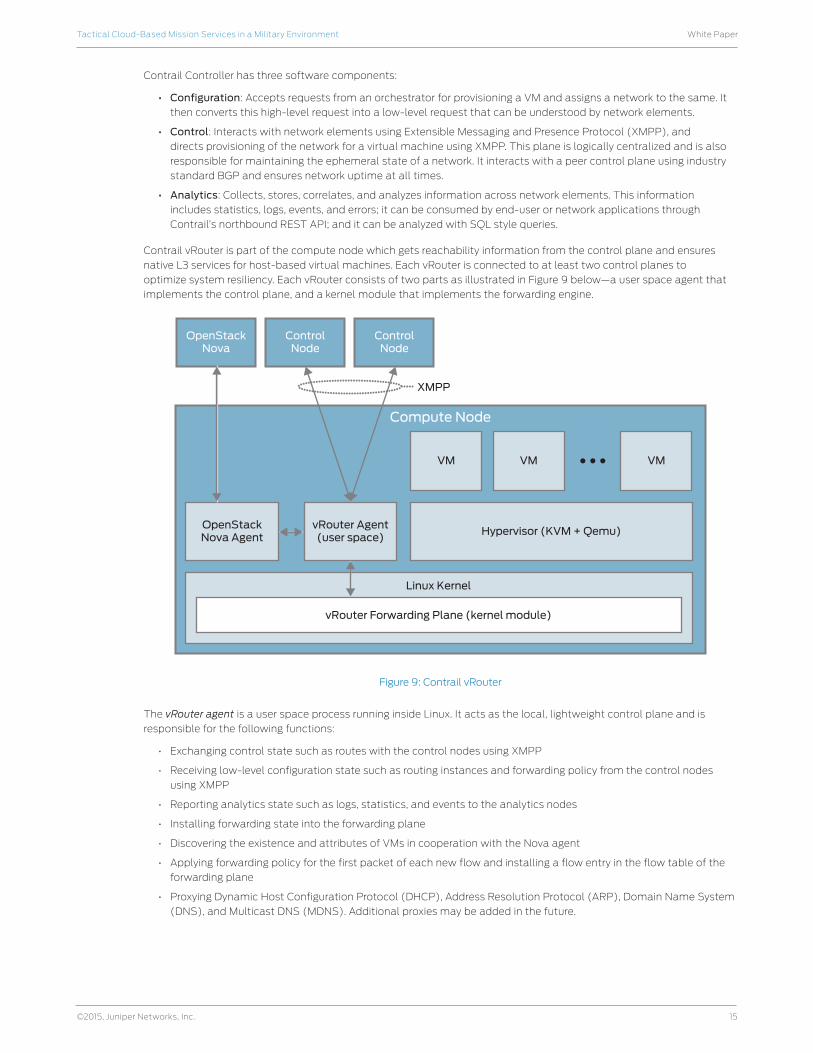
Contrail vRouter is part of the compute node which gets reachability information from the control plane and ensures
native L3 services for host-based virtual machines. Each vRouter is connected to at least two control planes to
optimize system resiliency. Each vRouter consists of two parts as illustrated in Figure 9 below—a user space agent that
implements the control plane, and a kernel module that implements the forwarding engine.
Figure 9: Contrail vRouter
The vRouter agent is a user space process running inside Linux. It acts as the local, lightweight control plane and is
responsible for the following functions:
• Exchanging control state such as routes with the control nodes using XMPP
• Receiving low-level configuration state such as routing instances and forwarding policy from the control nodes
using XMPP
• Reporting analytics state such as logs, statistics, and events to the analytics nodes
• Installing forwarding state into the forwarding plane
• Discovering the existence and attributes of VMs in cooperation with the Nova agent
• Applying forwarding policy for the first packet of each new flow and installing a flow entry in the flow table of the
forwarding plane
• Proxying Dynamic Host Configuration Protocol (DHCP), Address Resolution Protocol (ARP), Domain Name System
(DNS), and Multicast DNS (MDNS). Additional proxies may be added in the future.
Compute Node
OpenStackNova
ControlNode
ControlNode
vRouter Agent(user space)
Hypervisor (KVM + Qemu)
VM
Linux Kernel
vRouter Forwarding Plane (kernel module)
VM VM
OpenStackNova Agent
XMPP
16
White PaperTactical Cloud-Based Mission Services in a Military Environment
©2015, Juniper Networks, Inc.
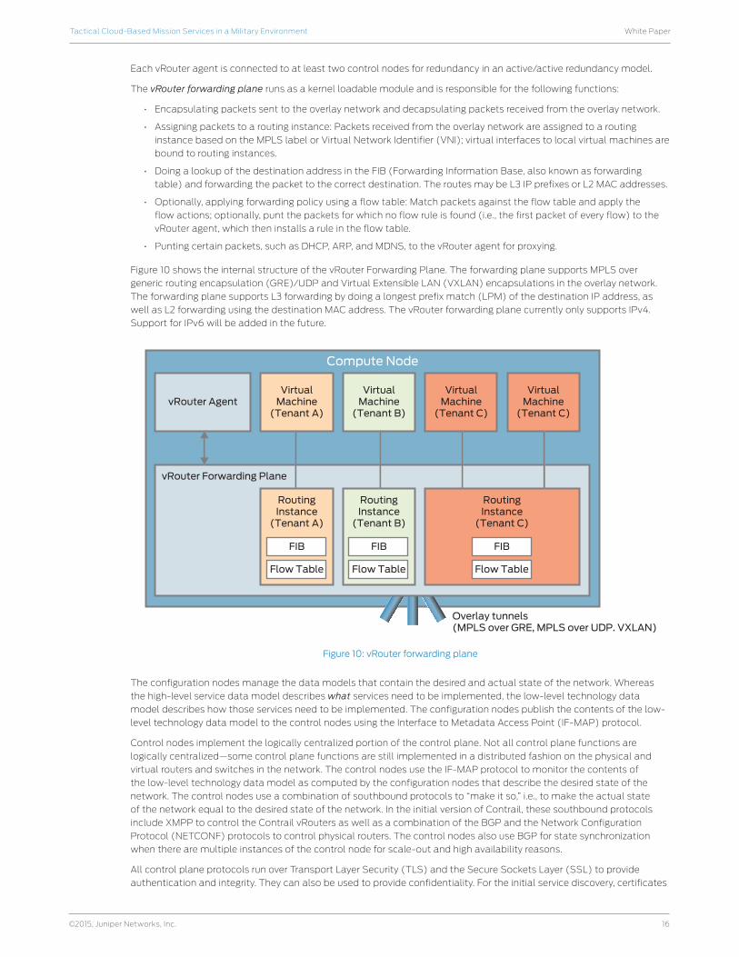
Each vRouter agent is connected to at least two control nodes for redundancy in an active/active redundancy model.
The vRouter forwarding plane runs as a kernel loadable module and is responsible for the following functions:
• Encapsulating packets sent to the overlay network and decapsulating packets received from the overlay network.
• Assigning packets to a routing instance: Packets received from the overlay network are assigned to a routing
instance based on the MPLS label or Virtual Network Identifier (VNI); virtual interfaces to local virtual machines are
bound to routing instances.
• Doing a lookup of the destination address in the FIB (Forwarding Information Base, also known as forwarding
table) and forwarding the packet to the correct destination. The routes may be L3 IP prefixes or L2 MAC addresses.
• Optionally, applying forwarding policy using a flow table: Match packets against the flow table and apply the
flow actions; optionally, punt the packets for which no flow rule is found (i.e., the first packet of every flow) to the
vRouter agent, which then installs a rule in the flow table.
• Punting certain packets, such as DHCP, ARP, and MDNS, to the vRouter agent for proxying.
Figure 10 shows the internal structure of the vRouter Forwarding Plane. The forwarding plane supports MPLS over
generic routing encapsulation (GRE)/UDP and Virtual Extensible LAN (VXLAN) encapsulations in the overlay network.
The forwarding plane supports L3 forwarding by doing a longest prefix match (LPM) of the destination IP address, as
well as L2 forwarding using the destination MAC address. The vRouter forwarding plane currently only supports IPv4.
Support for IPv6 will be added in the future.
Figure 10: vRouter forwarding plane
The configuration nodes manage the data models that contain the desired and actual state of the network. Whereas
the high-level service data model describes what services need to be implemented, the low-level technology data
model describes how those services need to be implemented. The configuration nodes publish the contents of the low-
level technology data model to the control nodes using the Interface to Metadata Access Point (IF-MAP) protocol.
Control nodes implement the logically centralized portion of the control plane. Not all control plane functions are
logically centralized—some control plane functions are still implemented in a distributed fashion on the physical and
virtual routers and switches in the network. The control nodes use the IF-MAP protocol to monitor the contents of
the low-level technology data model as computed by the configuration nodes that describe the desired state of the
network. The control nodes use a combination of southbound protocols to “make it so,” i.e., to make the actual state
of the network equal to the desired state of the network. In the initial version of Contrail, these southbound protocols
include XMPP to control the Contrail vRouters as well as a combination of the BGP and the Network Configuration
Protocol (NETCONF) protocols to control physical routers. The control nodes also use BGP for state synchronization
when there are multiple instances of the control node for scale-out and high availability reasons.
All control plane protocols run over Transport Layer Security (TLS) and the Secure Sockets Layer (SSL) to provide
authentication and integrity. They can also be used to provide confidentiality. For the initial service discovery, certificates
Compute Node
VirtualMachine
(Tenant C)
VirtualMachine
(Tenant C)
VirtualMachine
(Tenant B)
VirtualMachine
(Tenant A)
RoutingInstance
(Tenant C)
Overlay tunnels(MPLS over GRE, MPLS over UDP. VXLAN)
RoutingInstance
(Tenant B)
RoutingInstance
(Tenant A)
vRouter Agent
vRouter Forwarding Plane
FIB
Flow Table
FIB
Flow Table
FIB
Flow Table
17
White PaperTactical Cloud-Based Mission Services in a Military Environment
©2015, Juniper Networks, Inc.
are used for authentication. For all subsequent communications, token-based authentication is used for improved
performance. The service discovery server issues the tokens to both the servers and the clients over certificate-
authenticated TLS connections. The distribution of the certificates is out of the scope of this document. In practice,
this is typically handled by the server management system such as Puppet or Chef. All REST APIs in the system use
role-based authorization. Servers establish the identity of clients using TLS authentication and assign them one or more
roles. The roles determine what operations the client is allowed to perform over the interface (e.g., read-only versus
read-write) and which objects in the data model the client is allowed to access.
Load balancing is built right into the hypervisor forwarding plane for balancing of traffic across application tiers or
network services. Security policy enforcement and security groups are also built directly into the hypervisor forwarding
plane; application-aware firewall services are delivered in software using virtual Juniper Networks SRX Series Services
Gateways; and distributed threat prevention is delivered in software using Juniper Networks WebApp Secure. For resilient
VPN, L3VPN, Ethernet VPN (EVPN), site-to-site IPsec, and SSL VPN are all delivered in software. For high availability,
Contrail is configured in active/active cluster mode, and each vRouter is connected to a set of control planes and gets
the same routing table and access control lists (ACLs).
Juniper is delivering VXLAN routing capabilities on key Juniper platforms. VXLAN is a tunneling technology and is used
to create an overlay network in a VMware environment so that virtual machines can communicate with each other and
to enable the migration of VMs both within a data center and between data centers. Applications can be dynamically
spun up, turned down, or moved to support mission needs without encountering network barriers or constraints. VXLAN
routing allows application decisions to be centralized and managed independent of individual switches, routers, and
other data center devices in a VMware NSX environment. Juniper plans to offer VXLAN routing on the Juniper Networks
EX9200 Ethernet Switch and MX Series platforms by mid-2014. Both platforms are capable of operating independent
of VMware NSX with standard routing tables utilizing the capabilities of routing information bases (RIBs) and/or
forwarding information bases, also known as forwarding tables (FIBs), or by registering with VMware’s NSX controller to
provide external routing services. When registered with the NSX controller, the EX9200 and MX Series platforms can be
configured to provide Layer 3 gateway services via the VMware NSX API, allowing the NSX controller to coordinate the
creation of VXLAN tunnels.
Juniper recently announced support for EVPNs as a better way to transport VMs over the WAN. EVPN delivers multipoint
connectivity among Ethernet LAN sites across an MPLS backbone. It is similar to virtual private LAN service (VPLS) but
adds the capability to use BGP control plane-driven MAC address learning to avoid flooding of the network. It increases
the scale of MAC addresses and VLANs that can be supported. BGP capabilities such as constrained distribution, route
reflectors, and inter-AS are reused to provide better convergence in the event of network failures. Some organizations
see VXLAN as a more suitable technology for use within a data center, while EVPN is seen as being suited for use over
the WAN. Juniper has enabled extending VXLANs over the WAN by providing the capability to stitch VXLANs to EVPNs.
With the various tunnel types in use, there is still a need to optimize network broadcasting. Broadcast, Unknown Unicast
and Multicast (BUM) traffic can put an excessive load on a tactical cloud network. Layer 2 packets which have not been
learned by the switch must be flooded to all devices in a broadcast domain. BUM traffic must be processed efficiently
so that addresses can be resolved and data traffic can continue to flow in the event of VM moves. To solve this problem,
Juniper has implemented what we call the Overlay Packet Replicator (ORE) capability in the MX Series routers. The MX
Series can act as the data center edge device for L2 extension and as a gateway device between SDN systems. With ORE,
when the server needs to send a BUM packet, a proprietary packet is sent to the MX Series, which then converts the packet
into a standard multicast or broadcast packet and forwards it to all intended receivers. This is an optimal method because
the conversion and replication is done on purpose-built hardware using Juniper’s programmable silicon.
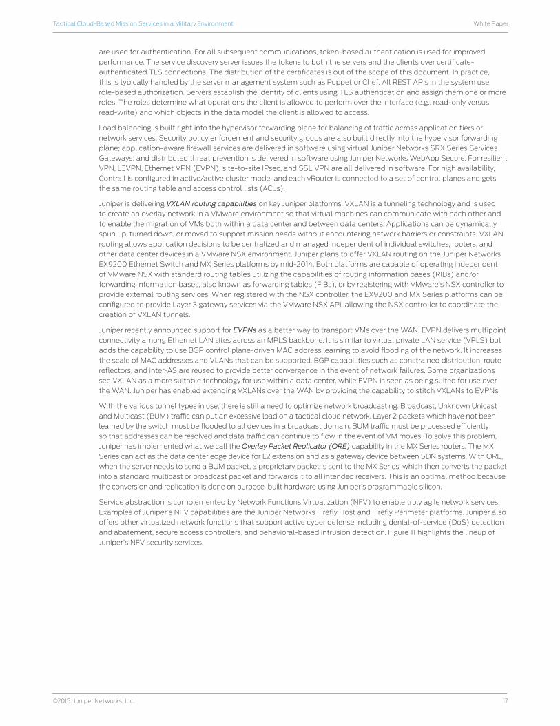
Service abstraction is complemented by Network Functions Virtualization (NFV) to enable truly agile network services.
Examples of Juniper’s NFV capabilities are the Juniper Networks Firefly Host and Firefly Perimeter platforms. Juniper also
offers other virtualized network functions that support active cyber defense including denial-of-service (DoS) detection
and abatement, secure access controllers, and behavioral-based intrusion detection. Figure 11 highlights the lineup of
Juniper’s NFV security services.
18
White PaperTactical Cloud-Based Mission Services in a Military Environment
©2015, Juniper Networks, Inc.
Figure 11: Juniper NFV security services
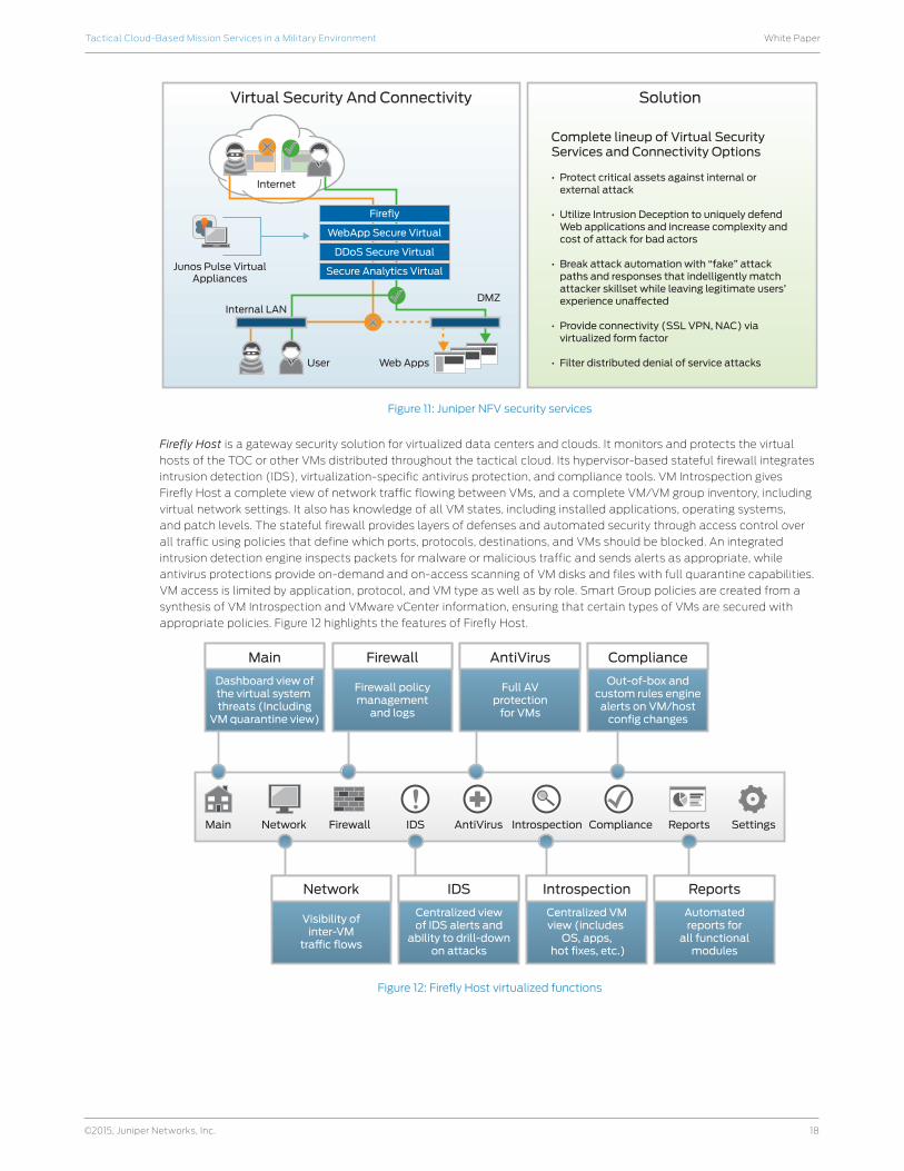
Firefly Host is a gateway security solution for virtualized data centers and clouds. It monitors and protects the virtual
hosts of the TOC or other VMs distributed throughout the tactical cloud. Its hypervisor-based stateful firewall integrates
intrusion detection (IDS), virtualization-specific antivirus protection, and compliance tools. VM Introspection gives
Firefly Host a complete view of network traffic flowing between VMs, and a complete VM/VM group inventory, including
virtual network settings. It also has knowledge of all VM states, including installed applications, operating systems,
and patch levels. The stateful firewall provides layers of defenses and automated security through access control over
all traffic using policies that define which ports, protocols, destinations, and VMs should be blocked. An integrated
intrusion detection engine inspects packets for malware or malicious traffic and sends alerts as appropriate, while
antivirus protections provide on-demand and on-access scanning of VM disks and files with full quarantine capabilities.
VM access is limited by application, protocol, and VM type as well as by role. Smart Group policies are created from a
synthesis of VM Introspection and VMware vCenter information, ensuring that certain types of VMs are secured with
appropriate policies. Figure 12 highlights the features of Firefly Host.
Figure 12: Firefly Host virtualized functions
Complete lineup of Virtual SecurityServices and Connectivity Options
• Protect critical assets against internal or external attack
• Utilize Intrusion Deception to uniquely defend Web applications and increase complexity and cost of attack for bad actors
• Break attack automation with “fake” attack paths and responses that indelligently match attacker skillset while leaving legitimate users’ experience una�ected
• Provide connectivity (SSL VPN, NAC) via virtualized form factor
• Filter distributed denial of service attacks
SolutionVirtual Security And Connectivity
Junos Pulse VirtualAppliances
Internal LAN
User Web Apps
DMZ
Internet
Firefly
WebApp Secure Virtual
DDoS Secure Virtual
Secure Analytics Virtual
Dashboard view ofthe virtual system threats (Including
VM quarantine view)
Main
Firewall policymanagement
and logs
Firewall
Full AVprotection
for VMs
AntiVirus
Out-of-box andcustom rules engine
alerts on VM/hostconfig changes
Compliance
Visibility ofinter-VM
tra c flows
Network
Centralized viewof IDS alerts and
ability to drill-downon attacks
IDS
Main Network Firewall IDS AntiVirus Introspection Compliance Reports Settings
Centralized VMview (includes
OS, apps, hot fixes, etc.)
Introspection
Automatedreports for
all functionalmodules
Reports

19
White PaperTactical Cloud-Based Mission Services in a Military Environment
©2015, Juniper Networks, Inc.
Firefly Perimeter is a virtual security appliance that runs on standard x86 hardware and a choice of hypervisors. It
leverages the Junos OS/SRX Series codebase. Figure 13 shows the key functions of this virtual appliance.
Figure 13: Firefly Perimeter virtual functions
In addition to these virtual functions, Firefly Perimeter also supports specific hypervisor functions, including vMotion,
snapshots, cloning, and templates for both VMware and kernel-based VM (KVM)/QEMU hypervisors. Because Firefly
Perimeter is based on standard x86 hardware, it can scale in three dimensions: vCPU, vNIC, vRAM. This ability to scale
through virtualization provides significant SWaP benefits for tactical cloud environments.
Figure 14 provides a notional architecture of a TOC that leverages SDN and NFV capabilities. As shown, the QFabric
System provides a seamless switching capability (1) that connects the tactical cloud services to the upper echelon
networks, and to the tactical core and edge networks. Meanwhile, the Contrail Controller (2) abstracts the physical
and virtual network services to provide the logical overlay network. This works in conjunction with an OpenStack VM
orchestration capability (3) to direct and control network services at the TOC. Contrail and OpenStack also provide
network diagnostics along with analytics support for network operations (4) via the Junos Space console. Appliance-
based security services provide perimeter protection (5), while virtual network security services (6) are service-chained
with mission cloud services to enable agile and secure mission applications.
Figure 14: Transformed TOC leveraging SDN and NFV capabilities
Firewall
Perimeter Security
VPN
NAT
Network AdmissionControl
Anti-Virus
Content
Junos Routing Protocols and SDK
IPS
Web Filtering
Anti-Spam
CLI, JWeb, SNMP, JSpace-SD, Hypervisor Management, HA/FT
Juson Rich and Extensible Security Stack
ApplicationAwareness
Application
IdentityAwareness
ServiceOrchestration
Contrail VNController
Physical Network
PhysicalNetwork
Virtual Network
Loosely Coupled(Overlay)
Network Orchestration,Diagnostics, Analytics
MPLS/VPLS NetworkEdge, WAN, Core
OpenStack/Orchestration
DeploymentAutomation
Appliance BasedServices
AGG LAYRRouter/Switch
TOR TOR
Analytics
So�ware IntegrationWith Underlay
DC GW/PERouter
DC GW/PERouter
vRouter vRouter vRouter
Bare Metal Server
QFabric®
Architecture
MX Series
SRX Series, WebAbb Secure,
SSL VPN, Firefly Suite
MX Series, EX Series, QFX Series
EX Series, QFX Series
vRouter
Virtual Services:Firefly and JWAS
VMs
Virtual Networks
20
White PaperTactical Cloud-Based Mission Services in a Military Environment
©2015, Juniper Networks, Inc.
Secure Gateway Router for Inter-Unit ConnectivityGateway routers are important elements to sustain mission optimized network operation and persistent connectivity for
a tactical cloud. Key capabilities needed by gateway routers include:
• Autonomous, mission optimized network operation
- Automatic IP-level radio-to-router flow control
- Quality-aware link and route selection
- Traffic-aware route selection
- Traffic load balancing
- Policy-based QoS control
- Network management function with support for network visualization, planning, and control
• Autonomous, mission persistent connectivity
- Dynamic neighbor discovery across radio cloud
- Automatic virtual link formation between adjacent routers
- Bandwidth conserving cut through routing across radio cloud
- Resilient mobility management service
- Bandwidth-efficient IP multicast in a red-black ad hoc network with automatic address deconfliction
- Reliable circuit-to-packet transport for backhaul of legacy voice and video applications
Juniper has developed a radio-to-router capability to support gateway protocols using our Juniper Networks LN Series
Rugged Secure Routers. LN Series routers come in modular and ruggedized versions making them ideal for warfighter
NOTM applications. Radio-router protocols allow a router whose only external link is a radio to adjust its behavior to
work reliably with a radio. Juniper can support NOTM environments for line of sight radios with Point-to-Point over
Ethernet (PPPoE)-based radio-router control protocol (RFC 4938) to shape the traffic; and, SATCOM radios with R2CP
radio-router control protocol to handle both “the burden of path decision” and “link metric calculation.” The LN Series
routers configured to support these protocols can scale up to ~1,000 PPPoE sessions per port and can support up to
4,095 sessions in total.
Juniper Networks CTP Series Circuit to Packet Platforms provide the advanced technology and features required to
reliably transport time-division multiplexing (TDM) and other circuit-based applications, such as video and legacy
voice, across next-generation IP/ MPLS networks. CTP Series has the field-proven flexibility, performance, and reliability,
required for circuit applications, including advanced clocking options and per-circuit buffers that enable end-to-end
timing and jitter removal to create a pseudowire across the IP/MPLS network. By bridging the legacy and IP world,
the CTP Series provides many unique features that enable cost reduction by eliminating point-to-point circuits and
convergence of all applications onto one IP/MPLS network.
Secure Network Access Many of the most troublesome and advanced threats affecting mission networks target endpoints. By compromising
a user endpoint, an attacker can establish a launch pad directly into backend mission systems. This makes it essential
that tactical cloud environments invest in the same kind of visibility and control over mobile endpoint devices as they
do on network-based controls for the tactical cloud. Since the health and integrity of any given endpoint impacts the
vulnerability of the entire cloud environment, it is necessary to assess and monitor the state of any network endpoint,
particularly mobile user endpoints, and consider the assessment result in tactical NAC decisions.
Juniper offers a network access control solution called Unified Access Control (UAC) that is designed in conjunction with
our endpoint security solution—Juniper Networks Junos Pulse—to meet these needs. UAC is a standards-based, access
control solution that delivers granular, secure, identity-enabled, location- and device-based access control, complete
with “follow-me” policies. UAC knows who and what is on the network, as well as when and where, and it applies the
appropriate access and security policies dynamically, even when the user travels from location to location. Junos Pulse
provides support for desktop, laptop, and mobile OS endpoints, including endpoint security checks before connection,
SSL VPN capability, single sign-on (SSO) to Web/cloud applications, and integration with UAC and other mobile device
management (MDM) providers such as Mobile Iron and AirWatch.
21
White PaperTactical Cloud-Based Mission Services in a Military Environment
©2015, Juniper Networks, Inc.
Table 1 highlights some of the key security capabilities of UAC and Junos Pulse.
Table 1: Security Highlights of UAC and Junos Pulse
Endpoint Profiling Identity Monitoring Access Control Service
Monitor the state of the network endpoints
Identity-based discovery of all network endpoints
Provide single sign-on (SSO) to Web applications including cloud-based SaaS applications using SAML 2.0
Detect events such as MAC spoofing, port swapping, etc.
Maintain real-time and historical contextual data for all endpoints, including addressing, location, behavior, etc.
Provide temporary access or allow provisioning of new devices
Run health check and integrity state measurements for endpoints
Allow MAC authentication for endpoints not running an authentication client
Provide L2/802.1X admission control, L3 (firewall-based) access control, or both
The combination of Junos Pulse and UAC also facilitates a secure, agile, mobile user experience through the ability to
migrate sessions and support identity federation. Table 2 provides an overview of how the user experience is supported.
Table 2: UAC and Pulse User Experience
Garrison Garrison Tactical Tactical
1. User wakes up PC to read e-mail
2. Junos Pulse sees that user is remote
3. SSL VPN selected as access type
4. User authenticates
5. SSL VPN provisioned
6. Application acceleration deployed
1. User goes for coffee; wakes up PC
2. Junos Pulse sees that user is remote
3. SSL VPN selected as access type
4. User connected directly to hotspot via iPass
5. No authentication needed; session still valid
1. User is in Stryker and wakes laptop
2. Junos Pulse determines that user is on the tactical net (wired or wireless; 802.1X or L3)
3. UAC/NAC selected as access type
4. No authentication needed; session data migrated (via IF-MAP); session still valid
1. User diismounts; needs to check e-mail or on status of an order in a tactical application
2. Clicks on Junos Pulse on smartphone or tablet
3. User authenticates
4. Secure network and application access provisioned via SSL VPN to smartphone or tablet
UAC supports network access control using the Trusted Network Connect (TNC) security architecture. This architecture,
which is part of the standards specifications provided by the Trusted Computing Group (TCG), includes a health check
agent for the endpoint, a trusted reporting agent that securely reports the health check information, and a backend
infrastructure to consume this health check information and make access grant/deny decisions.
In addition to health check components, the TNC architecture has specified a protocol (IF-MAP), which is the same
capability leveraged by Contrail to support control of NFVs. IF-MAP allows network devices to publish or consume
security and network relevant metadata with the Metadata Access Point (MAP) Server. The metadata may reflect
access decisions by policy enforcement points (PEPs), device state such as bandwidth utilization or configuration status
of endpoints, or other metadata. Figure 15 depicts the role of a MAP server to support cyber situational awareness
among different network elements.
Figure 15: Role of MAP server
IPAM
PhysicalSecurity
EmbeddedSystems
AAA
PolicyDecision
Point (PDP)
EndpointSecurity
(via NAC)
MAP/CMDB
IF-MAP Protocol
AssetManagementSystem/MDM
SDNController
FirewallsWirelessSwitchingHIDSNIDS
SIM/SEM
DLP

22
White PaperTactical Cloud-Based Mission Services in a Military Environment
©2015, Juniper Networks, Inc.
From a tactical cloud perspective where resource constraints must be balanced with access, QoS is also a factor when
making access decisions, such as denying or rate limiting traffic if the given network conditions are overloaded with
higher priority traffic. IF-MAP also enables real-time situational awareness of network and security conditions, so if
sessions are initially allowed and network conditions change, the UAC system can learn of the changed condition via the
MAP server, and then react with denial of new sessions or possibly terminate existing sessions.
Wireless AccessIn addition to UAC, Juniper also offers SmartPass Connect. SmartPass Connect is designed to provide quick, easy access
to enterprise networks by providing automated, self-service onboarding for a wide array of BYOD and enterprise-owned
device types. Using both username/password-based 802.1X methods as well as certificate-based methods, SmartPass
Connect provides fast, simple, fail-safe access to a secure network. Additionally, the SmartPass Connect integration
module for Microsoft Certificate Authority (CA) allows client certificates to be deployed from an existing Microsoft CA to
a wide array of devices in an automated, self-service manner.
For example, when an unknown device connects to a provisioning service set identifier (SSID) or guest wired port, the
session is captured and redirected to the SmartPass Connect server. SmartPass Connect pushes a platform appropriate
“dissolving” agent to the client device. The configuration agent takes input from the user (such as username/password)
and configures the native supplicant with the appropriate type of 802.1X access, secure SSID name, and other parameters.
Once the client is provisioned, the agent migrates the device to the secure SSID, verifies that the transition to the secure
network has completed successfully, and then dissolves itself automatically from the client device. For certificate-based
authentication, the provisioning portal collects user credentials from the wizard, validates against Active Directory, and
requests a device certificate on behalf of the user. The wizard gets the secure SSID configuration profile along with the
necessary device certificates, manages the secure network transition, and then it dissolves itself as well.
SmartPass also provides a view into guest and employee session information on the wireless LAN to the extended
network infrastructure (firewalls, wired IPD/IDS systems, etc.) using the TNC IF-MAP protocol. SmartPass acts as a
MAP client publishing state information to a MAP server to enable applications such as unified policy enforcement (for
guests and employees) and role management. By taking advantage of existing standards-based RADIUS and MAP
infrastructures, SmartPass allows for privileges and authorization attributes to be adjusted dynamically, even during
the middle of a networking session. Authorization adjustments can be based not only on a user’s identity, but also on
where users are, what they are doing, what time and day it is, and what others around them are doing as well. Besides
a user’s physical location or change in location, SmartPass can dynamically adjust access privileges based on a user’s
SSID, VLAN, time of day, device, and predetermined conditions from RADIUS accounting such as session life or amount
of traffic passed. If a user on the network is consuming an excessive amount of bandwidth, SmartPass throttles down
bandwidth and priority for that user after a utilization threshold is crossed within an allotted time period. SmartPass
also supports geo-fencing by creating a perimeter RF firewall for a building, preventing anyone outside the firewall from
accessing the network, even if they have legitimate credentials.
SmartPass’ centralized architecture also allows for captive portals. This provides an easy, device independent method
for authenticating guests and other temporary users via a Web portal. SmartPass only keeps one instance of a captive
portal, which is served up to any user at any location no matter which of the Juniper Networks WLC Series Wireless
LAN Controllers is managing the user’s authentication. This reduces the maintenance of replication on every controller
when changes occur. The centralized architecture also reduces the cost of SSL certificates. Instead of needing one per
controller, only a single certificate is needed on the SmartPass server.
Optimizations for Networking on the Move (NOTM)This section describes various tactical cloud network optimizations that are possible through the use of Juniper SDN
technology and NFV.
SDN and SONNetworking technologies such as IP-based SDRs that use the SRW and ANW2 waveforms, LTE 4G, Cloud RAN (C-RAN),
and RAN 2.0 are characterized as Self-Organizing Networks (SONs). SON is an automation technology designed to
make the planning, configuration, management, optimization, and healing of mobile radio access networks simpler
and faster. For example, the LTE specification inherently supports SON features like Automatic Neighbor Relation
(ANR) detection. Newly added base stations should be self-configured in line with a “plug-and-play” paradigm, while
all operational base stations will regularly self-optimize parameters and algorithmic behavior in response to observed
network performance and radio conditions. Furthermore, self-healing mechanisms can be triggered to temporarily
compensate for a detected equipment outage, while awaiting a more permanent solution.
SDN capability can complement the functions of an SON. For example, the SDN control plane will have the capability
to interface with the SON layer in a 4G LTE network within the radio access network to accommodate all of the required
updates within the backhaul network and handle the associated updates or reconfigurations in the radio layer. Tight
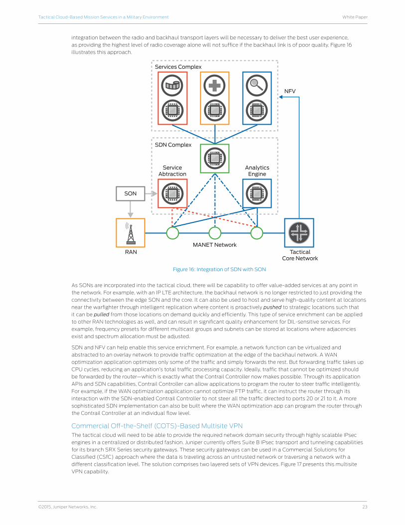
23
White PaperTactical Cloud-Based Mission Services in a Military Environment
©2015, Juniper Networks, Inc.
integration between the radio and backhaul transport layers will be necessary to deliver the best user experience,
as providing the highest level of radio coverage alone will not suffice if the backhaul link is of poor quality. Figure 16
illustrates this approach.
Figure 16: Integration of SDN with SON
As SONs are incorporated into the tactical cloud, there will be capability to offer value-added services at any point in
the network. For example, with an IP LTE architecture, the backhaul network is no longer restricted to just providing the
connectivity between the edge SON and the core. It can also be used to host and serve high-quality content at locations
near the warfighter through intelligent replication where content is proactively pushed to strategic locations such that
it can be pulled from those locations on demand quickly and efficiently. This type of service enrichment can be applied
to other RAN technologies as well, and can result in significant quality enhancement for DIL-sensitive services. For
example, frequency presets for different multicast groups and subnets can be stored at locations where adjacencies
exist and spectrum allocation must be adjusted.
SDN and NFV can help enable this service enrichment. For example, a network function can be virtualized and
abstracted to an overlay network to provide traffic optimization at the edge of the backhaul network. A WAN
optimization application optimizes only some of the traffic and simply forwards the rest. But forwarding traffic takes up
CPU cycles, reducing an application’s total traffic processing capacity. Ideally, traffic that cannot be optimized should
be forwarded by the router—which is exactly what the Contrail Controller now makes possible. Through its application
APIs and SDN capabilities, Contrail Controller can allow applications to program the router to steer traffic intelligently.
For example, if the WAN optimization application cannot optimize FTP traffic, it can instruct the router through its
interaction with the SDN-enabled Contrail Controller to not steer all the traffic directed to ports 20 or 21 to it. A more
sophisticated SDN implementation can also be built where the WAN optimization app can program the router through
the Contrail Controller at an individual flow level.
Commercial Off-the-Shelf (COTS)-Based Multisite VPNThe tactical cloud will need to be able to provide the required network domain security through highly scalable IPsec
engines in a centralized or distributed fashion. Juniper currently offers Suite B IPsec transport and tunneling capabilities
for its branch SRX Series security gateways. These security gateways can be used in a Commercial Solutions for
Classified (CSfC) approach where the data is traveling across an untrusted network or traversing a network with a
different classification level. The solution comprises two layered sets of VPN devices. Figure 17 presents this multisite
VPN capability.
Services Complex
SDN Complex
ServiceAbtraction
AnalyticsEngine
MANET NetworkRAN Tactical
Core Network
NFV
SON
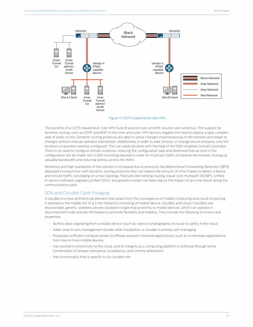
24
White PaperTactical Cloud-Based Mission Services in a Military Environment
©2015, Juniper Networks, Inc.
Figure 17: COTS-based Multi-site VPN
The benefits of a COTS-based Multi-Site VPN Suite B solution over a HAIPE solution are numerous. The support for
dynamic routing, such as OSPF and BGP, in the inner and outer VPN devices negates the need to deploy a rigid, complex
web of static routes. Dynamic routing protocols are able to sense changes instantaneously in the network and adapt to
changes without manual operator intervention. Additionally, in order to add, remove, or change secure enclaves, only the
locations in question need be configured. This can easily be done with the help of the SDN-enabled Contrail Controller.
There is no need to configure remote locations, reducing the configuration task and likelihood that an error in the
configuration will be made. Nor is GRE tunneling required in order for multicast traffic to traverse the enclave, freeing up
valuable bandwidth and reducing latency across the WAN.
Resiliency and high availability of the solution is increased due to protocols like Bidirectional Forwarding Detection (BFD)
deployed in conjunction with dynamic routing protocols that can reduce the amount of time it takes to detect a failure
and reroute traffic converging on a new topology. Features like nonstop routing, equal-cost multipath (ECMP), unified
in-service software upgrade (unified ISSU), and graceful restart can help reduce the impact of any one failure along the
communication path.
SDN and Cloudlet Cyber ForagingA cloudlet is a new architectural element that arises from the convergence of mobile computing and cloud computing.
It represents the middle tier of a 3-tier hierarchy consisting of mobile device, cloudlet, and cloud. Cloudlets are
discoverable, generic, stateless servers located in single-hop proximity to mobile devices, which can operate in
disconnected mode and are VM-based to promote flexibility and mobility. They include the following functions and
properties:
• Buffers data originating from a mobile device (such as video or photographs) en route to safety in the cloud
• Adds close to zero management burden after installation; a cloudlet is entirely self-managing
• Possesses sufficient compute power to offload resource-intensive applications, such as multimedia applications,
from one or more mobile devices
• Has excellent connectivity to the cloud, and its integrity as a computing platform is enforced through some
combination of tamper-resistance, surveillance, and runtime attestation
• Has functionality that is specific to its cloudlet role
Black Network
SRX650
Grey Network
Vendor XIPSECcapabledevice
Vendor XIPSEC
capabledevice
Site B ClientSite A Client InnerTunnel
CA
InnerTunnelAdmin/
AuditServer
Grey Network
Red Network
SRX650 BlackNetwork
OuterTunnelAdmin/
AuditServer
OuterTunnel
CA
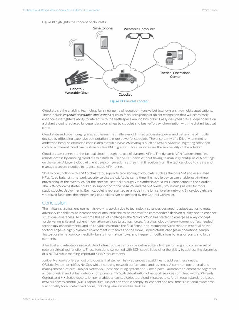
25
White PaperTactical Cloud-Based Mission Services in a Military Environment
©2015, Juniper Networks, Inc.
Figure 18 highlights the concept of cloudlets.
Figure 18: Cloudlet concept
Cloudlets are the enabling technology for a new genre of resource-intensive but latency-sensitive mobile applications.
These include cognitive assistance applications such as facial recognition or object recognition that will seamlessly
enhance a warfighter’s ability to interact with the battlespace around him or her. Easily disrupted critical dependence on
a distant cloud is replaced by dependence on a nearby cloudlet and best-effort synchronization with the distant tactical
cloud.
Cloudlet-based cyber foraging also addresses the challenges of limited processing power and battery life of mobile
devices by offloading expensive computation to more powerful cloudlets. The uncertainty of a DIL environment is
addressed because offloaded code is deployed in a basic VM manager such as KVM or VMware. Migrating offloaded
code to a different cloud can be done via live VM migration. This also increases the survivability of the solution.
Cloudlets can connect to the tactical cloud through the use of dynamic VPNs. The dynamic VPN feature simplifies
remote access by enabling cloudlets to establish IPsec VPN tunnels without having to manually configure VPN settings
on the server. A Layer 3 cloudlet client uses configuration settings that it receives from the tactical cloud to create and
manage a secure cloudlet-to-tactical cloud VPN tunnel.
SDN, in conjunction with a VM orchestrator, supports provisioning of cloudlets, such as the base VM and associated
NFVs (load balancing, network security services, etc.). At the same time, the mobile device can enable just-in-time
provisioning of the overlay VM for the specific user task through VM synthesis over a Wi-Fi connection to the cloudlet.
The SDN/VM orchestrator could also support both the base VM and the VM overlay provisioning as well for more
static cloudlet deployments. Each cloudlet is represented as a node in the logical overlay network. Since cloudlets are
virtualized functions, their networking capabilities can be directed by the Contrail Controller.
ConclusionThe military’s tactical environment is evolving quickly due to technology advances designed to adapt tactics to match
adversary capabilities, to increase operational efficiencies, to improve the commander’s decision quality, and to enhance
situational awareness. To overcome this set of challenges, the tactical cloud has started to emerge as a key concept
for delivering agile and resilient information services to tactical forces. A tactical cloud-like environment offers needed
technology enhancements, and its capabilities enable the fluid sense-and-respond services that are essential at the
tactical edge—a highly dynamic environment with forces on the move, unpredictable changes in operational tempo,
fluctuations in network connectivity, bursty information flows, and frequent modifications to mission plans and force
elements.
A tactical and adaptable network cloud infrastructure can only be delivered by a high performing and cohesive set of
network virtualized functions. These functions, combined with SDN capabilities, offer the ability to address the dynamics
of a NOTM, while meeting important SWaP requirements.
Juniper Networks offers a host of products that deliver highly advanced capabilities to address these needs.
QFabric System simplifies NetOps while improving network performance and resiliency. A common operational and
management platform—Juniper Networks Junos® operating system and Junos Space—automates element management
across physical and virtual network components. Through virtualization of network services combined with SDN-ready
Contrail and MX Series routers, Juniper enables an agile, distributed, cloud infrastructure. And through standards-based
network access control (NAC) capabilities, Juniper can enable comply-to-connect and real-time situational awareness
functionality for all networked nodes, including wireless mobile devices.
Tactical OperationsCenter
Cloudlet
HandtalkWearable Glove
Tablet
Smartphone Wearable Computer

Corporate and Sales Headquarters
Juniper Networks, Inc.
1133 Innovation Way
Sunnyvale, CA 94089 USA
Phone: 888.JUNIPER (888.586.4737)
or +1.408.745.2000
Fax: +1.408.745.2100
www.juniper.net
Copyright 2015 Juniper Networks, Inc. All rights reserved. Juniper Networks, the Juniper Networks logo, Junos
and QFabric are registered trademarks of Juniper Networks, Inc. in the United States and other countries.
All other trademarks, service marks, registered marks, or registered service marks are the property of their
respective owners. Juniper Networks assumes no responsibility for any inaccuracies in this document. Juniper
Networks reserves the right to change, modify, transfer, or otherwise revise this publication without notice.
APAC and EMEA Headquarters
Juniper Networks International B.V.
Boeing Avenue 240
1119 PZ Schiphol-Rijk
Amsterdam, The Netherlands
Phone: +31.0.207.125.700
Fax: +31.0.207.125.701
White PaperTactical Cloud-Based Mission Services in a Military Environment
2000562-001-EN Sept 2015
About Juniper NetworksJuniper Networks is in the business of network innovation. From devices to data centers, from consumers to cloud
providers, Juniper Networks delivers the software, silicon and systems that transform the experience and economics
of networking. The company serves customers and partners worldwide. Additional information can be found at
www.juniper.net.