taiwan union technology corporation · 2.5.5.2 (network analyzer ) 2.5.5.9 ( impendence analyzer )...
TRANSCRIPT

www.tuc.com.tw
Signal Integrity

2
Factors influencing Signal Integrity
3
Studying Factors
Studied the following factors
Resin system
Fabric
Construction
Conductor
Moisture
Temperature
Test method
Confidential & Proprietary

4
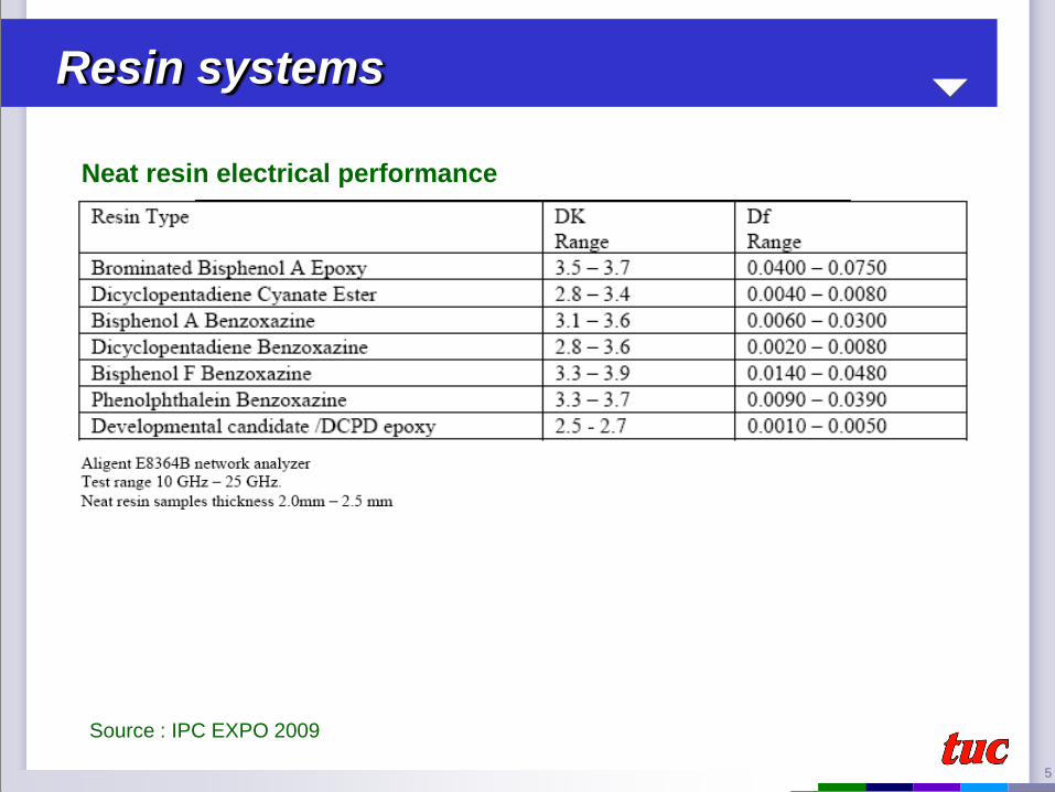
Resin systems
5
Neat resin electrical performance
Source : IPC EXPO 2009
Resin systems
6
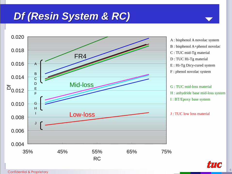
Df (Resin System & RC)
RC
75%
0.004
0.006
0.008
0.010
0.012
0.014
0.016
0.018
0.020
35% 45% 55% 65%
Df
A
B
C
D
E
F
G
H
I
J
Mid-loss G : TUC mid-loss material
H : anhydride base mid-loss system
I : BT/Epoxy base system
Low-loss J : TUC low loss material
A : bisphenol A novolac system
B : bisphenol A+phenol novolac
C : TUC mid-Tg material
D : TUC Hi-Tg material
E : Hi-Tg Dicy-cured system
F : phenol novolac system
FR4
Confidential & Proprietary
7
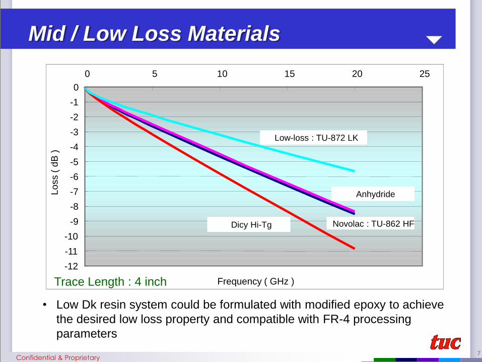
Mid / Low Loss Materials
-12
-11
-10
-9
-8
-7
-6
-5
-4
-3
-2
-1
0
0 5 10 15 20 25
Frequency ( GHz )
Lo
ss (
dB
)
Anhydride
Novolac : TU-862 HF Dicy Hi-Tg
Low-loss : TU-872 LK
Trace Length : 4 inch
Confidential & Proprietary
• Low Dk resin system could be formulated with modified epoxy to achieve
the desired low loss property and compatible with FR-4 processing
parameters

8
Construction
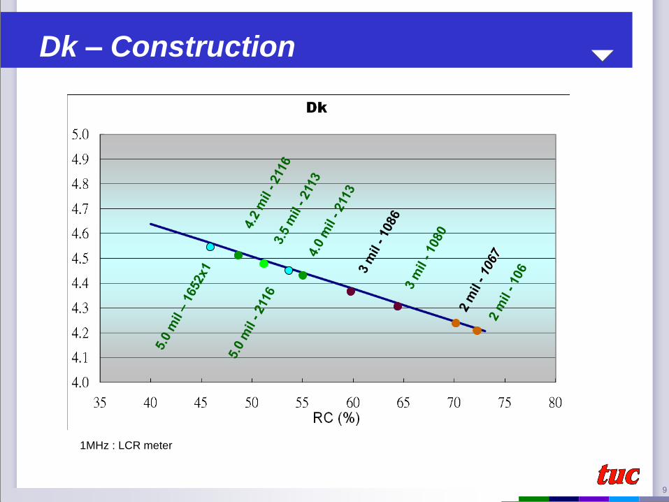
9
1MHz : LCR meter
Dk – Construction

10
1MHz : LCR meter
Df – Construction
11
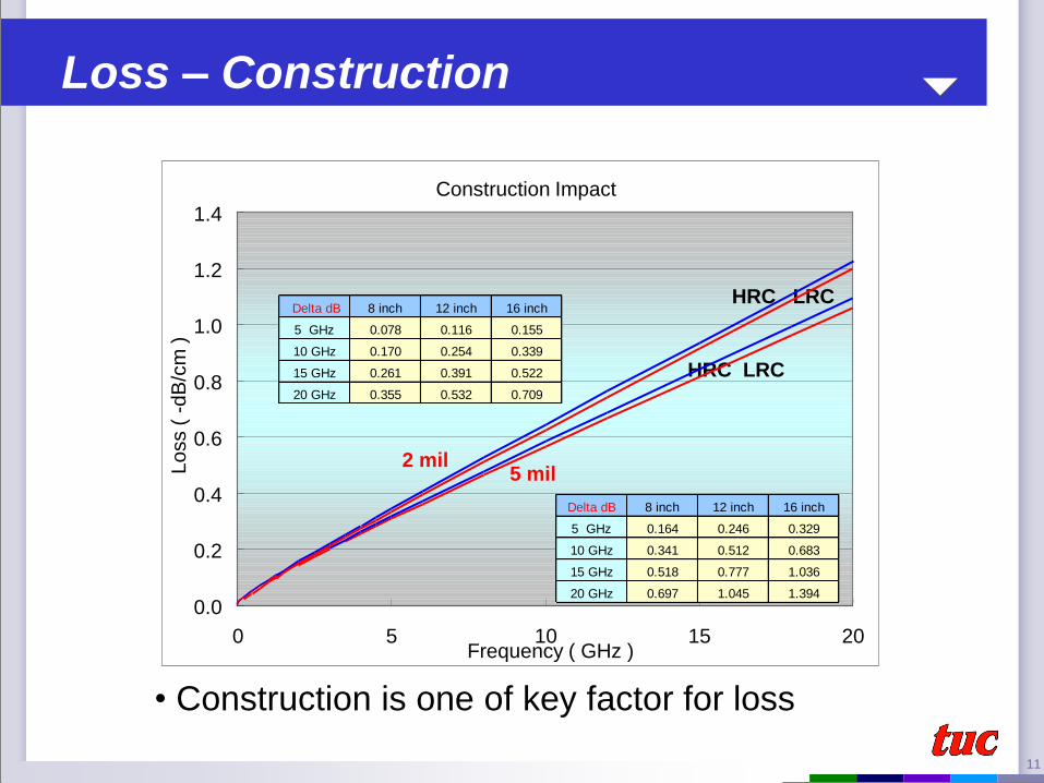
Loss – Construction
• Construction is one of key factor for loss
Construction Impact
0.0
0.2
0.4
0.6
0.8
1.0
1.2
1.4
0 5 10 15 20 Frequency ( GHz )
Lo
ss (
-d
B/c
m )
HRC LRC
HRC LRC
2 mil 5 mil
Delta dB 8 inch 12 inch 16 inch
5 GHz 0.164 0.246 0.329
10 GHz 0.341 0.512 0.683
15 GHz 0.518 0.777 1.036
20 GHz 0.697 1.045 1.394
Delta dB 8 inch 12 inch 16 inch
5 GHz 0.078 0.116 0.155
10 GHz 0.170 0.254 0.339
15 GHz 0.261 0.391 0.522
20 GHz 0.355 0.532 0.709

12
Fabric
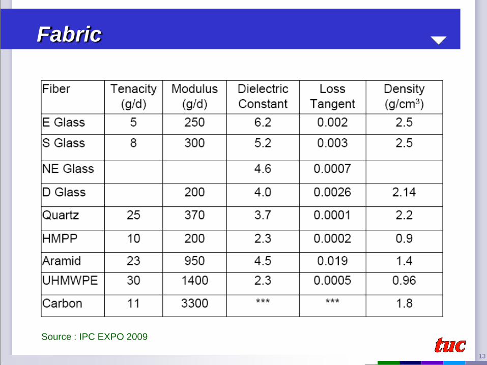
13
Fabric
Source : IPC EXPO 2009
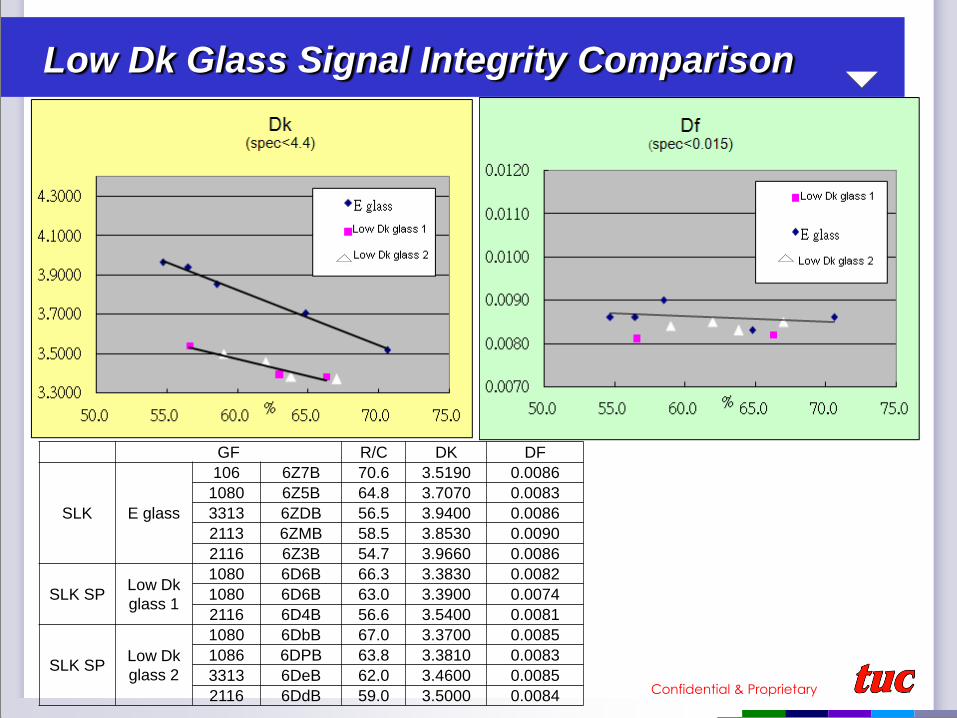
Low Dk Glass Signal Integrity Comparison
GF R/C DK DF
SLK E glass
106 6Z7B 70.6 3.5190 0.0086
1080 6Z5B 64.8 3.7070 0.0083
3313 6ZDB 56.5 3.9400 0.0086
2113 6ZMB 58.5 3.8530 0.0090
2116 6Z3B 54.7 3.9660 0.0086
SLK SP Low Dk
glass 1
1080 6D6B 66.3 3.3830 0.0082
1080 6D6B 63.0 3.3900 0.0074
2116 6D4B 56.6 3.5400 0.0081
SLK SP Low Dk
glass 2
1080 6DbB 67.0 3.3700 0.0085
1086 6DPB 63.8 3.3810 0.0083
3313 6DeB 62.0 3.4600 0.0085
2116 6DdB 59.0 3.5000 0.0084 Confidential & Proprietary
Low Dk Glass Signal Integrity Comparison
• The Dk of CCL reduces approximately by 0.30 -0.45
(depends on the RC) and 0.001 on Df when E glass
replaces with low Dk glass on the same resin system
Confidential & Proprietary

16
Resin rich Resin poor
Resin Dk ~ 3.2 Glass Dk ~ 5.6
Signal Skew – Differential circuit
Special Layout and Routing
Designer Rotates Image
Lopsided glass weaving
Confidential & Proprietary
17
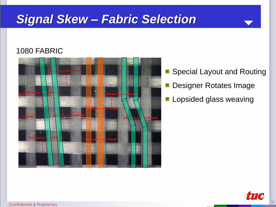
1080 FABRIC
Signal Skew – Fabric Selection
Special Layout and Routing
Designer Rotates Image
Lopsided glass weaving
Confidential & Proprietary
18
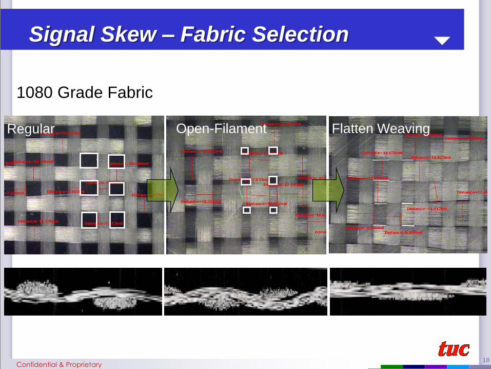
Regular Open-Filament Flatten Weaving
1080 Grade Fabric
Signal Skew – Fabric Selection
Confidential & Proprietary
19
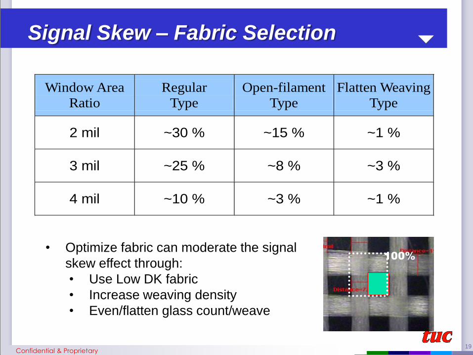
Window Area
Ratio
Regular
Type
Open-filament
Type
Flatten Weaving
Type
2 mil ~30 % ~15 % ~1 %
3 mil ~25 % ~8 % ~3 %
4 mil ~10 % ~3 % ~1 %
Signal Skew – Fabric Selection
100%
• Optimize fabric can moderate the signal
skew effect through:
• Use Low DK fabric
• Increase weaving density
• Even/flatten glass count/weave
Confidential & Proprietary

20
Conductor
21
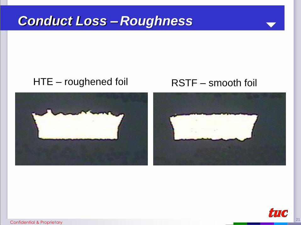
HTE – roughened foil RSTF – smooth foil
Conduct Loss – Roughness
Confidential & Proprietary

22
F
G
Circuit trace surface roughness level
Type Position sample N
HTE Foil F : Shinny side 14 0.115 mil
G : matte side 14 0.313 mil
RTF Foil F : Shinny side 14 0.192 mil
G : matte side 14 0.207 mil
Roughness
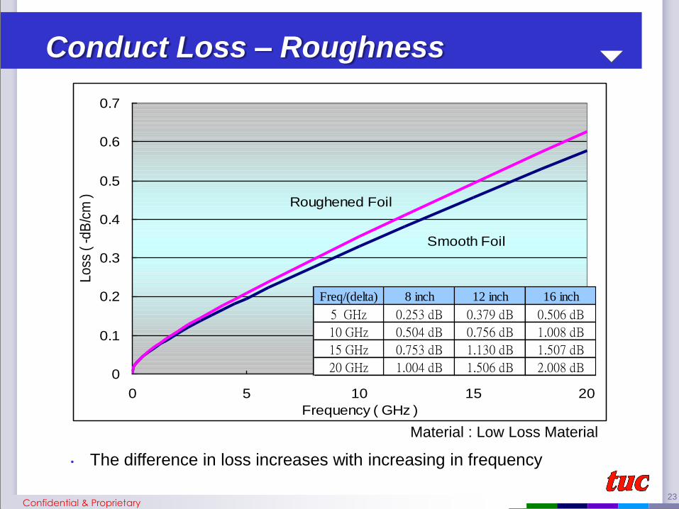
Conduct Loss – Roughness
Confidential & Proprietary
23
0
0.1
0.2
0.3
0.4
0.5
0.6
0.7
0 5 10 15 20
Frequency ( GHz )
Lo
ss (
-d
B/c
m )
Smooth Foil
Roughened Foil
Conduct Loss – Roughness
Freq/(delta) 8 inch 12 inch 16 inch
5 GHz 0.253 dB 0.379 dB 0.506 dB
10 GHz 0.504 dB 0.756 dB 1.008 dB
15 GHz 0.753 dB 1.130 dB 1.507 dB
20 GHz 1.004 dB 1.506 dB 2.008 dB
Material : Low Loss Material
Confidential & Proprietary
• The difference in loss increases with increasing in frequency
24
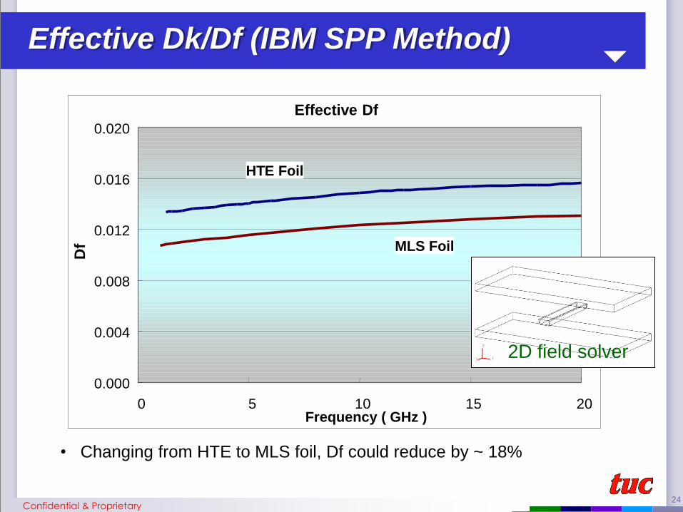
Effective Dk/Df (IBM SPP Method)
Effective Df
0.000
0.004
0.008
0.012
0.016
0.020
0 5 10 15 20 Frequency ( GHz )
Df
HTE Foil
MLS Foil
2D field solver
Confidential & Proprietary
• Changing from HTE to MLS foil, Df could reduce by ~ 18%

25
Temperature

26
Influence of Temp.
PN cured High Tg FR4
SPP method
Confidential & Proprietary
• Temp increases from ambient temperature to 70C could cause Df
deteriorate by ~20%

27
Moisture
28
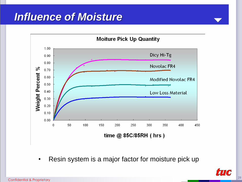
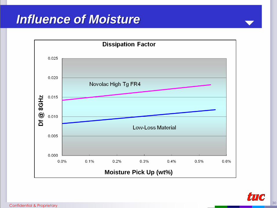
Influence of Moisture
• Resin system is a major factor for moisture pick up
Confidential & Proprietary
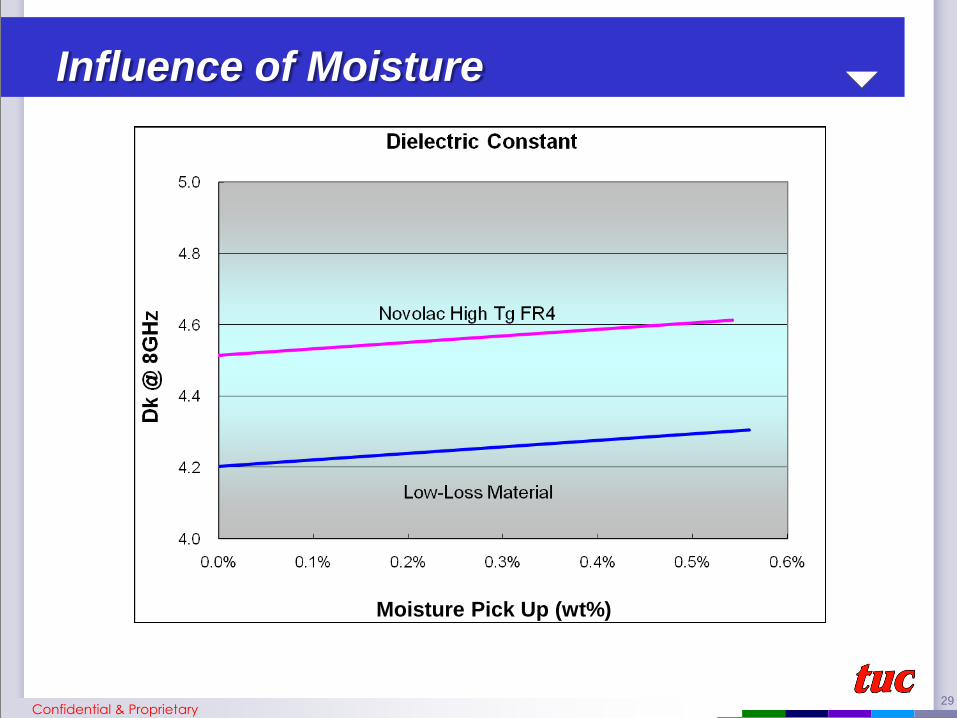
29
Influence of Moisture
Moisture Pick Up (wt%)
Confidential & Proprietary
30
Moisture Pick Up (wt%)
Influence of Moisture
Confidential & Proprietary

31
Oxide Treatment

32
Influence of Oxide Treatment
Source : 2009 IPC APEX / Cisco / S20_02
HVLP
VLP
STD
• The oxide tooth also will affect the SI. Shorter the tooth,
lower the interference

33
Measuring Method
34
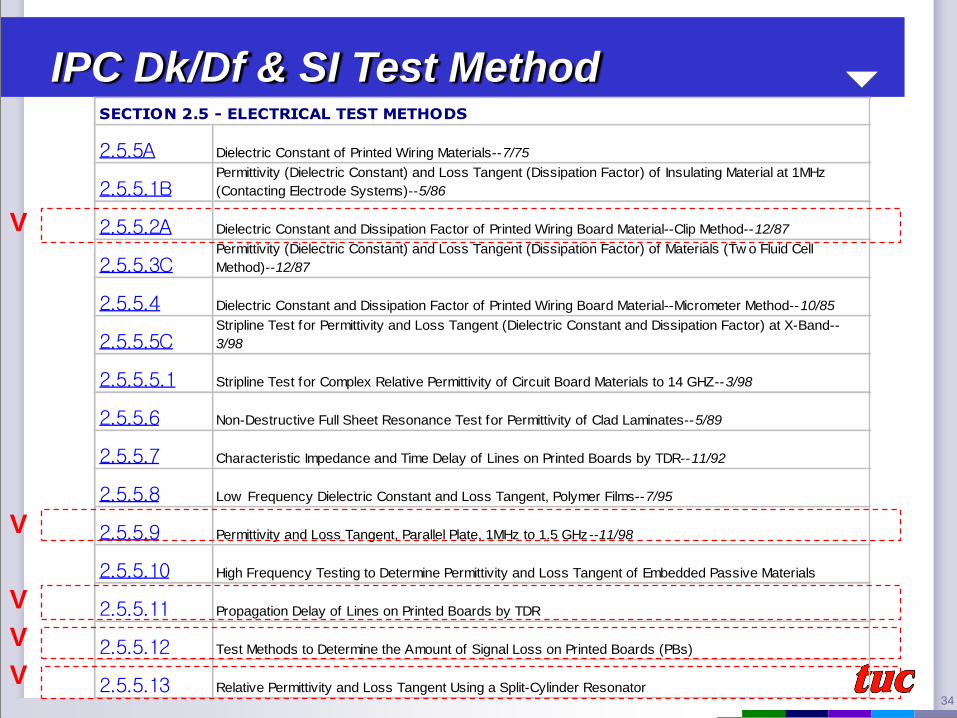
SECTION 2.5 - ELECTRICAL TEST METHODS
2.5.5A Dielectric Constant of Printed Wiring Materials--7/75
2.5.5.1BPermittivity (Dielectric Constant) and Loss Tangent (Dissipation Factor) of Insulating Material at 1MHz
(Contacting Electrode Systems)--5/86
2.5.5.2A Dielectric Constant and Dissipation Factor of Printed Wiring Board Material--Clip Method--12/87
2.5.5.3CPermittivity (Dielectric Constant) and Loss Tangent (Dissipation Factor) of Materials (Tw o Fluid Cell
Method)--12/87
2.5.5.4 Dielectric Constant and Dissipation Factor of Printed Wiring Board Material--Micrometer Method--10/85
2.5.5.5CStripline Test for Permittivity and Loss Tangent (Dielectric Constant and Dissipation Factor) at X-Band--
3/98
2.5.5.5.1 Stripline Test for Complex Relative Permittivity of Circuit Board Materials to 14 GHZ--3/98
2.5.5.6 Non-Destructive Full Sheet Resonance Test for Permittivity of Clad Laminates--5/89
2.5.5.7 Characteristic Impedance and Time Delay of Lines on Printed Boards by TDR--11/92
2.5.5.8 Low Frequency Dielectric Constant and Loss Tangent, Polymer Films--7/95
2.5.5.9 Permittivity and Loss Tangent, Parallel Plate, 1MHz to 1.5 GHz--11/98
2.5.5.10 High Frequency Testing to Determine Permittivity and Loss Tangent of Embedded Passive Materials
2.5.5.11 Propagation Delay of Lines on Printed Boards by TDR
2.5.5.12 Test Methods to Determine the Amount of Signal Loss on Printed Boards (PBs)
2.5.5.13 Relative Permittivity and Loss Tangent Using a Split-Cylinder Resonator
IPC Dk/Df & SI Test Method
V
V
V
V
V
35
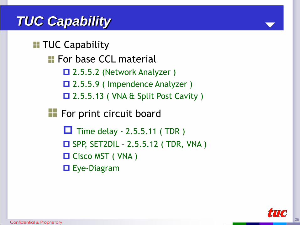
TUC Capability
For base CCL material
2.5.5.2 (Network Analyzer )
2.5.5.9 ( Impendence Analyzer )
2.5.5.13 ( VNA & Split Post Cavity )
For print circuit board
Time delay - 2.5.5.11 ( TDR )
SPP, SET2DIL – 2.5.5.12 ( TDR, VNA )
Cisco MST ( VNA )
Eye-Diagram
TUC Capability
Confidential & Proprietary

36
Test equipment : HP E4980A
Frequency range : 20KHz~2MHz
From Cp=E0XErX(A/d) to estimated Dk value of material at low
frequency .
D show material Dissipation factor values.
E0= 8.854X10^-12 F/M
Er= the Dk of material
d: thickness
A: Area
IPC 2.5.5.2
Confidential & Proprietary
37
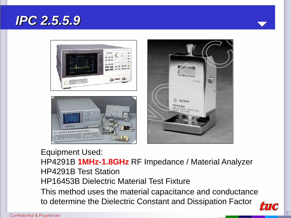
Equipment Used:
HP4291B 1MHz-1.8GHz RF Impedance / Material Analyzer
HP4291B Test Station
HP16453B Dielectric Material Test Fixture
This method uses the material capacitance and conductance
to determine the Dielectric Constant and Dissipation Factor
IPC 2.5.5.9
Confidential & Proprietary

38
For resonant measurements, the Dielectric Constant is
determined from measurements of the resonance
frequency and quality factor
The Q=f0/f, where ‘f0’ is the resonance frequency and ‘∆f’ is the
frequency difference between 3dB points
Equipment used : Vector Network Analizar R&S ZVB 20
VNA available frequency range : 10MHz~20GHz
Fixtures working frequency : Split Post Cavity
@1.0GHz @3.0GHz @5.0GHz @10GHz
VNA SPC Fixture
IPC 2.5.5.13
Confidential & Proprietary
39
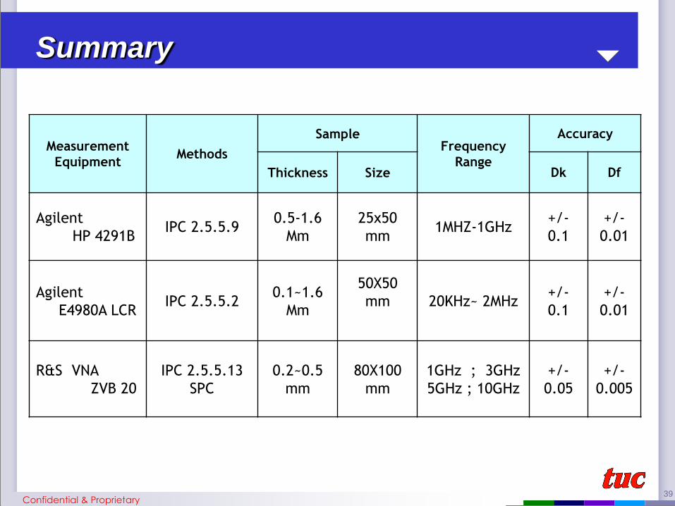
Measurement
Equipment Methods
Sample Frequency
Range
Accuracy
Thickness Size Dk Df
Agilent
HP 4291B IPC 2.5.5.9
0.5-1.6
Mm
25x50
mm 1MHZ-1GHz
+/-
0.1
+/-
0.01
Agilent
E4980A LCR IPC 2.5.5.2
0.1~1.6
Mm
50X50
mm
20KHz~ 2MHz +/-
0.1
+/-
0.01
R&S VNA
ZVB 20
IPC 2.5.5.13
SPC
0.2~0.5
mm
80X100
mm
1GHz ; 3GHz
5GHz ; 10GHz
+/-
0.05
+/-
0.005
Summary
Confidential & Proprietary
40
Insertion Loss Measurement
41
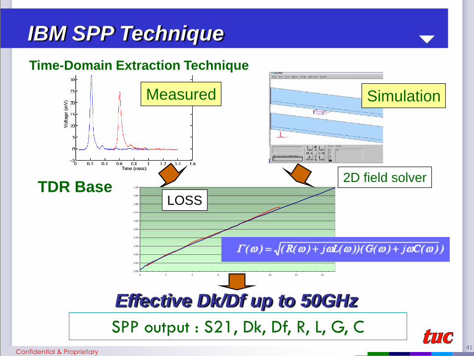
IBM SPP Technique
0.00
0.10
0.20
0.30
0.40
0.50
0.60
0.70
0.80
0.90
1.00
0 2 4 6 8 10 12 14
LOSS
Measured Simulation
Effective Dk/Df up to 50GHz
2D field solver TDR Base
Time-Domain Extraction Technique
SPP output : S21, Dk, Df, R, L, G, C
Confidential & Proprietary

42
Effective Dk/Df - including
Dielectric Dk & Df
Trace effect
Oxide treatment
Foil roughness
Skin effect PCB
CCL
+
IBM SPP Technique
Confidential & Proprietary
43
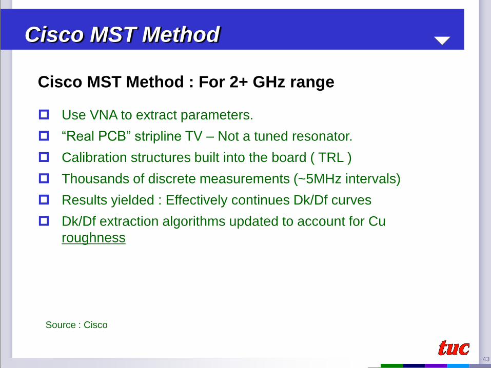
Cisco MST Method
Cisco MST Method : For 2+ GHz range
Use VNA to extract parameters.
“Real PCB” stripline TV – Not a tuned resonator.
Calibration structures built into the board ( TRL )
Thousands of discrete measurements (~5MHz intervals)
Results yielded : Effectively continues Dk/Df curves
Dk/Df extraction algorithms updated to account for Cu
roughness
Source : Cisco

44
Source : Cisco
Cisco MST Method
45
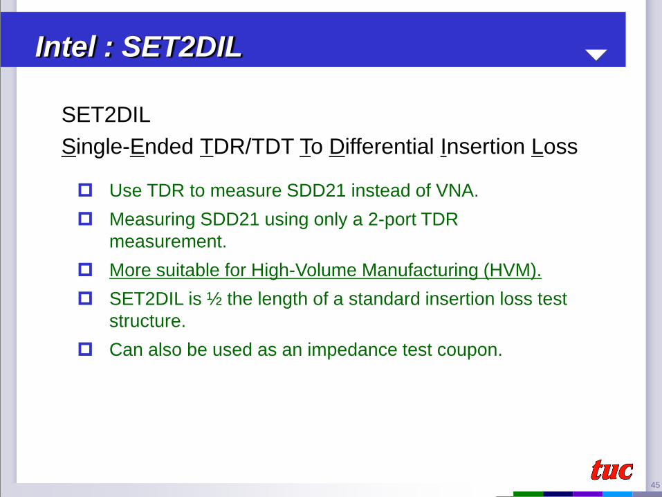
Intel : SET2DIL
SET2DIL
Single-Ended TDR/TDT To Differential Insertion Loss
Use TDR to measure SDD21 instead of VNA.
Measuring SDD21 using only a 2-port TDR
measurement.
More suitable for High-Volume Manufacturing (HVM).
SET2DIL is ½ the length of a standard insertion loss test
structure.
Can also be used as an impedance test coupon.
46
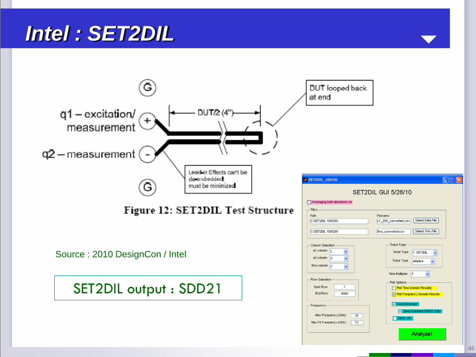
Intel : SET2DIL
Source : 2010 DesignCon / Intel
SET2DIL output : SDD21

47
Measurement results
• Measurement results vary with test method
Confidential & Proprietary
Material
Type Resin RC %
SPC SPP
Dk Df Dk Df Insertion loss
(-db/inch)
@4 GHz @8 GHz @4 GHz @8 GHz @4 GHz @8 GHz @4 GHz @8 GHz @4 GHz @8 GHz
TU-862
HF
Rich 70 3.84 4.37 0.0141 0.0150 3.90 3.87 0.0187 0.0191 0.682 1.168
Poor 50 4.41 3.81 0.0174 0.0182 4.38 4.34 0.0168 0.0173 0.623 1.097
TU-872
LK
Rich 70 3.37 3.35 0.0087 0.0089 3.52 3.50 0.0126 0.0131 0.529 0.892
Poor 50 3.89 3.87 0.0081 0.0084 3.90 3.88 0.0110 0.0115 0.481 0.811
SET2DIL
Material Df @ 1GHz Foil Layer 4GHz 8GHz
(dB/inch) (dB/inch)
TU-862 HF 0.01
HTE L3 -0.581 -0.967
TU-862 HF HTE L6 -0.579 -0.965
TU-872 LK 0.008
MLS L3 -0.401 -0.793
TU-872 LK MLS L6 -0.398 -0.789

48
Loss Dominants

49
Attenuation = f ( frequency )
= Dielectric loss + Conductor loss
= Loss ( base material ) + Loss ( circuit trace )
= Material Dk / Df + Circuit Geometry and Roughness
Loss Elements (SPP Method)
Confidential & Proprietary

50
Loss Dominator
~1.5GHz
Overall Loss
Conduct Loss
Dielectric Loss
FR4
Breakdown element
RTF foil
Confidential & Proprietary
51
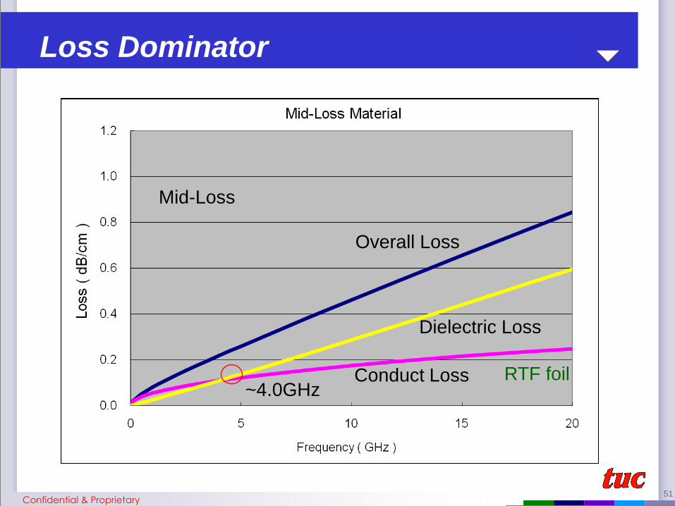
~4.0GHz
Loss Dominator
Overall Loss
Conduct Loss
Dielectric Loss
Mid-Loss
RTF foil
Confidential & Proprietary
52
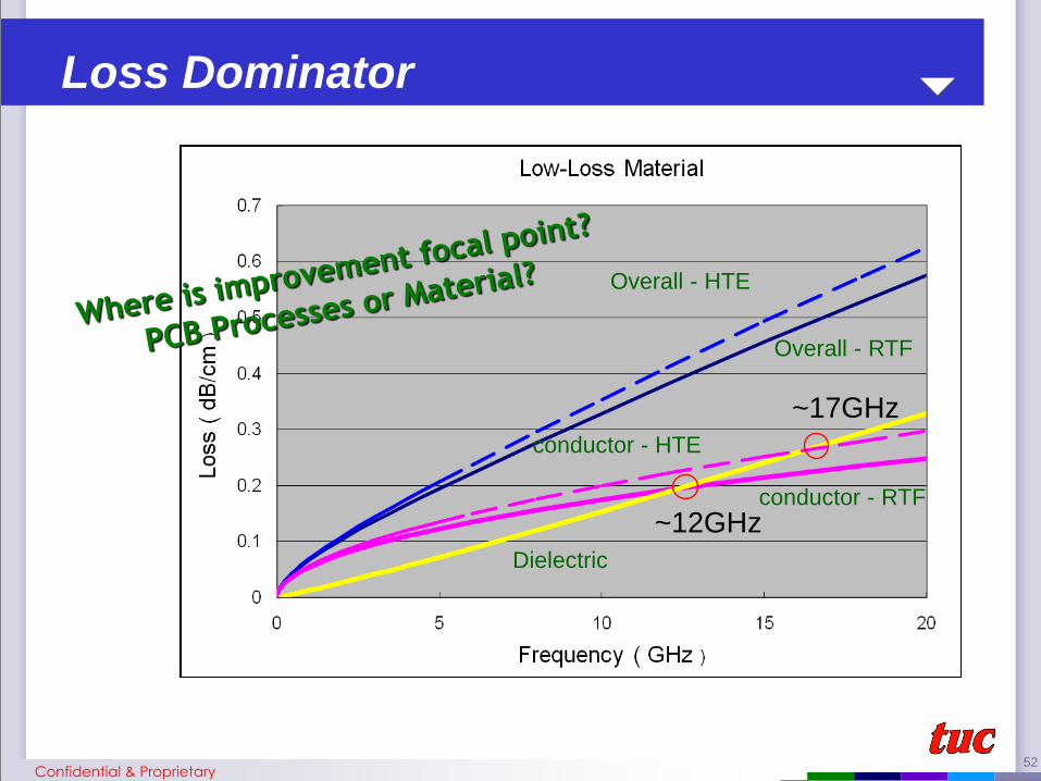
Loss Dominator
Overall - HTE
Overall - RTF
conductor - HTE
conductor - RTF
Dielectric
~12GHz
~17GHz
Confidential & Proprietary

53
Loss Elements (SPP Method)
Confidential & Proprietary
• Before the breakeven point (circle with red), the conductor will carry more
weight age in total loss than material. After cross over the breakeven point,
material will have higher effect on the total loss than conductor
• Break even point will be shifted to the right when moving from standard loss
to very low loss material
• Before the breakeven point, improvement should focus on improving the
processes like oxide type, copper tooth or copper etch rate. However, after
the breakeven point, the total loss can be reduced effectively through
selecting a lower loss property material
• Copper becomes a critical factor when moving toward from standard loss
application to very low loss application

54
Product Copper
Construction
Oxide
Moisture Temp.
Test Method
Fabric
Signal
Integrity
Factors influencing Signal Integrity
Confidential & Proprietary
